New Holland Electronic Service Tool TM Series Tractors Operator’s Manual Instant Download (Publicati

Page 1

87033671 4/03
Tractors
Electronic Service Tool TMSeries
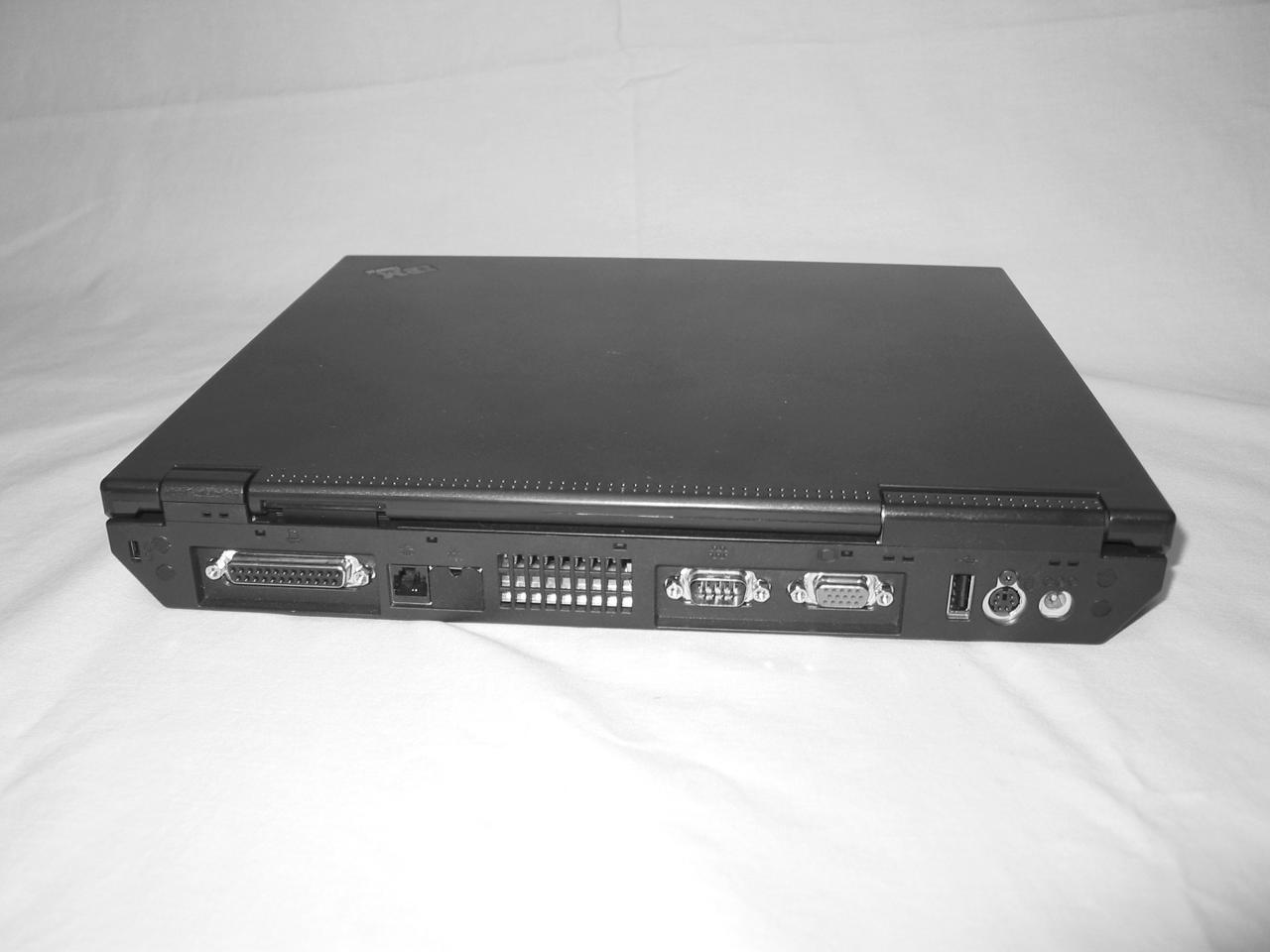
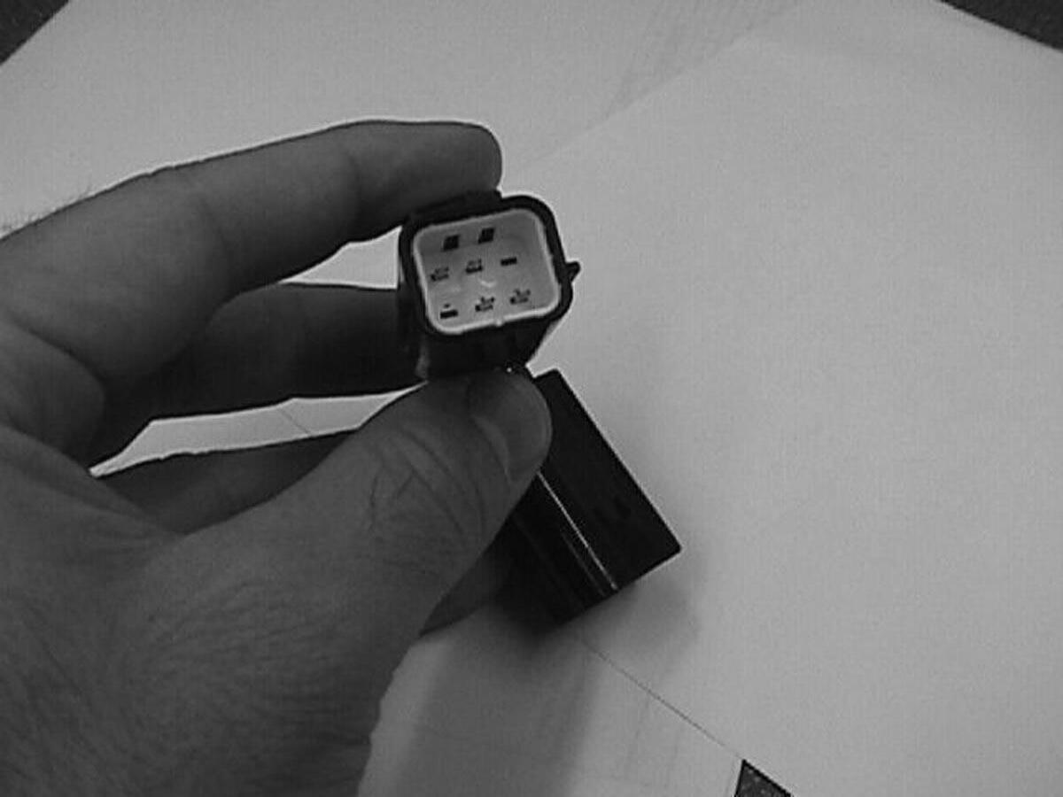
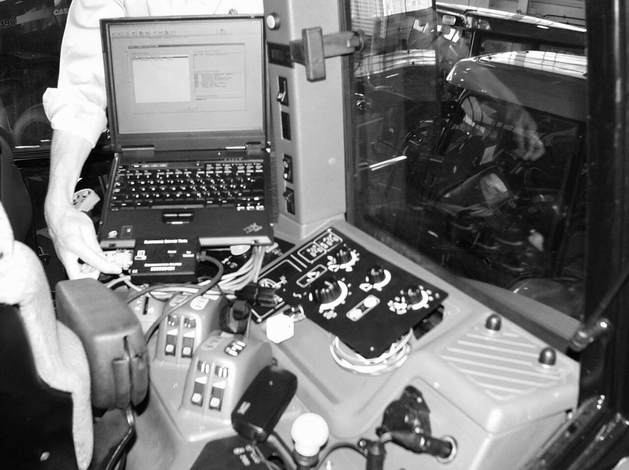
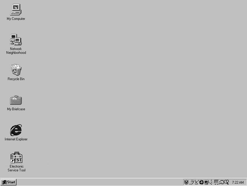
i-1 Electronic Service Tool - TM Series Tractors Electronic Service Tool - TM Series Tractors General Information Electronic Service Tool Components Electronic Service Tool. . . . . . . . . . . . . . . . . . . . . . . . . . . . . . . . . . . . . . . . . . . . . . . . . . . . 3 Electronic Service Tool Computer Port Identification. . . . . . . . . . . . . . . . . . . . . . . . . . . . . 4 Electronic Service Tool Cable Connections. . . . . . . . . . . . . . . . . . . . . . . . . . . . . . . . . . . . 5 Electronic Service Tool Controller Communication Adapters. . . . . . . . . . . . . . . . . . . . . . . 6 Vehicle Connections. . . . . . . . . . . . . . . . . . . . . . . . . . . . . . . . . . . . . . . . . . . . . . . . . . . . . . 7 Remove the console cover. Locate the CAN programming/diagnostic connectors.. . . . . . 8 Electronic Service Tool Placement. . . . . . . . . . . . . . . . . . . . . . . . . . . . . . . . . . . . . . . . . . 11 Desktop Display . . . . . . . . . . . . . . . . . . . . . . . . . . . . . . . . . . . . . . . . . . . . . . . . . . . . . . . . 13 Connector Selection and Diagnostic Login Vehicle Connector Selection . . . . . . . . . . . . . . . . . . . . . . . . . . . . . . . . . . . . . . . . . . . . . . 15 Diagnostics Login. . . . . . . . . . . . . . . . . . . . . . . . . . . . . . . . . . . . . . . . . . . . . . . . . . . . . . . 16 Selecting An Electronic Service Tool Vehicle Application Electronic Service Tool Screen Components Application Title . . . . . . . . . . . . . . . . . . . . . . . . . . . . . . . . . . . . . . . . . . . . . . . . . . . . . . . . 19 Tool Bar (Screen Function) Identification Icon. . . . . . . . . . . . . . . . . . . . . . . . . . . . . . . . . 19 Screen Function Identification . . . . . . . . . . . . . . . . . . . . . . . . . . . . . . . . . . . . . . . . . . . . . 21 Minimize, Restore, Close Buttons . . . . . . . . . . . . . . . . . . . . . . . . . . . . . . . . . . . . . . . . . . 21 Function Buttons (Dark = Active; Gray = Inactive). . . . . . . . . . . . . . . . . . . . . . . . . . . . . . 21 Comm Link Status (Communication Status). . . . . . . . . . . . . . . . . . . . . . . . . . . . . . . . . . . 22 Pull Down Menus . . . . . . . . . . . . . . . . . . . . . . . . . . . . . . . . . . . . . . . . . . . . . . . . . . . . . . . 22 EST Pull Down Menus File . . . . . . . . . . . . . . . . . . . . . . . . . . . . . . . . . . . . . . . . . . . . . . . . . . . . . . . . . . . . . . . . . . 24 Tool. . . . . . . . . . . . . . . . . . . . . . . . . . . . . . . . . . . . . . . . . . . . . . . . . . . . . . . . . . . . . . . . . . 25 View . . . . . . . . . . . . . . . . . . . . . . . . . . . . . . . . . . . . . . . . . . . . . . . . . . . . . . . . . . . . . . . . . 26 Communication. . . . . . . . . . . . . . . . . . . . . . . . . . . . . . . . . . . . . . . . . . . . . . . . . . . . . . . . . 27 Options - Connector Selection and Diagnostic Login. . . . . . . . . . . . . . . . . . . . . . . . . . . . 28
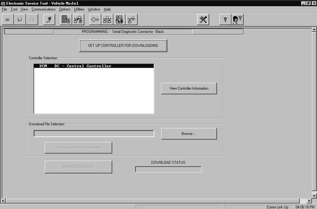
i-2 Window . . . . . . . . . . . . . . . . . . . . . . . . . . . . . . . . . . . . . . . . . . . . . . . . . . . . . . . . . . . . . . .29 Help. . . . . . . . . . . . . . . . . . . . . . . . . . . . . . . . . . . . . . . . . . . . . . . . . . . . . . . . . . . . . . . . . .29 Vehicle Connector Selection Programming Screen Set Up Controllers For Downloading. . . . . . . . . . . . . . . . . . . . . . . . . . . . . . . . . . . . . . . . .33 Select a File For Downloading . . . . . . . . . . . . . . . . . . . . . . . . . . . . . . . . . . . . . . . . . . . . .35 Download File Information. . . . . . . . . . . . . . . . . . . . . . . . . . . . . . . . . . . . . . . . . . . . . . . . .37 Download File . . . . . . . . . . . . . . . . . . . . . . . . . . . . . . . . . . . . . . . . . . . . . . . . . . . . . . . . . .39 Download Status. . . . . . . . . . . . . . . . . . . . . . . . . . . . . . . . . . . . . . . . . . . . . . . . . . . . . . . .41 Controller Status Screen Controller Version Information — One Controller . . . . . . . . . . . . . . . . . . . . . . . . . . . . . . .44 Controller Version Information — All Controllers. . . . . . . . . . . . . . . . . . . . . . . . . . . . . . . .47 User Entry Labels . . . . . . . . . . . . . . . . . . . . . . . . . . . . . . . . . . . . . . . . . . . . . . . . . . . . . . . 49 Save Information To Disk . . . . . . . . . . . . . . . . . . . . . . . . . . . . . . . . . . . . . . . . . . . . . . . . .50 Open File From Disk. . . . . . . . . . . . . . . . . . . . . . . . . . . . . . . . . . . . . . . . . . . . . . . . . . . . .51 Diagnostics Login Retrieve Controller Faults Screen View Faults — One Controller. . . . . . . . . . . . . . . . . . . . . . . . . . . . . . . . . . . . . . . . . . . . . .58 Troubleshoot Problem. . . . . . . . . . . . . . . . . . . . . . . . . . . . . . . . . . . . . . . . . . . . . . . . . . . .60 View List of Defined Faults . . . . . . . . . . . . . . . . . . . . . . . . . . . . . . . . . . . . . . . . . . . . . . . .63 Clearing Stored Fault Codes. . . . . . . . . . . . . . . . . . . . . . . . . . . . . . . . . . . . . . . . . . . . . . .65 View Faults — All Controllers . . . . . . . . . . . . . . . . . . . . . . . . . . . . . . . . . . . . . . . . . . . . . .67 User Entry Labels . . . . . . . . . . . . . . . . . . . . . . . . . . . . . . . . . . . . . . . . . . . . . . . . . . . . . . . 69 Save Information To Disk . . . . . . . . . . . . . . . . . . . . . . . . . . . . . . . . . . . . . . . . . . . . . . . . .70 Open File From Disk. . . . . . . . . . . . . . . . . . . . . . . . . . . . . . . . . . . . . . . . . . . . . . . . . . . . .71 Sorting. . . . . . . . . . . . . . . . . . . . . . . . . . . . . . . . . . . . . . . . . . . . . . . . . . . . . . . . . . . . . . . .73 Monitor Screen Save Information To Disk . . . . . . . . . . . . . . . . . . . . . . . . . . . . . . . . . . . . . . . . . . . . . . . . .84 Open File From Disk. . . . . . . . . . . . . . . . . . . . . . . . . . . . . . . . . . . . . . . . . . . . . . . . . . . . .85 Set Output Screen
i-3 Troubleshoot Problem Screen Troubleshoot Problem Screen (Screen Function) Icons. . . . . . . . . . . . . . . . . . . . . . . . . 100 Viewing Fault Information. . . . . . . . . . . . . . . . . . . . . . . . . . . . . . . . . . . . . . . . . . . . . . . . 101 Linked Troubleshooting Information. . . . . . . . . . . . . . . . . . . . . . . . . . . . . . . . . . . . . . . . 103 Back Button . . . . . . . . . . . . . . . . . . . . . . . . . . . . . . . . . . . . . . . . . . . . . . . . . . . . . . . . . . 104 Schematic Information . . . . . . . . . . . . . . . . . . . . . . . . . . . . . . . . . . . . . . . . . . . . . . . . . . 105 Contents. . . . . . . . . . . . . . . . . . . . . . . . . . . . . . . . . . . . . . . . . . . . . . . . . . . . . . . . . . . . . 106 Components Information . . . . . . . . . . . . . . . . . . . . . . . . . . . . . . . . . . . . . . . . . . . . . . . . 107 Help On Item User Help Contents Tab . . . . . . . . . . . . . . . . . . . . . . . . . . . . . . . . . . . . . . . . . . . . . . . . . . . . . . . . . 115 Index Tab . . . . . . . . . . . . . . . . . . . . . . . . . . . . . . . . . . . . . . . . . . . . . . . . . . . . . . . . . . . . 115 Find Tab. . . . . . . . . . . . . . . . . . . . . . . . . . . . . . . . . . . . . . . . . . . . . . . . . . . . . . . . . . . . . 116 Print Button. . . . . . . . . . . . . . . . . . . . . . . . . . . . . . . . . . . . . . . . . . . . . . . . . . . . . . . . . . . 116 Exit . . . . . . . . . . . . . . . . . . . . . . . . . . . . . . . . . . . . . . . . . . . . . . . . . . . . . . . . . . . . . . . . . 116 Shutting Down the Electronic Service Tool
i-4
1
Tractors
Electronic Service Tool - TM Series
Electronic Service Tool User’s Manual

Electronic Service Tool - TM Series Tractors

Section 1: General Information

The Electronic Service Tool is a laptop computer based service and diagnostic tool that communicates with the vehicle (tractor, combine, implement, etc.) data bus. The Electronic Service Tool will:

•Display the controller software version information.

•Retrieve fault codes stored within controllers.

•Monitor switch and sensor parameter information.

•Download software to controllers.

•Provide a Windows based link to the Engine Diagnostic Tool, Engine Diagnostic Tool Help, and Engine Calibration Download Tool.

•Configure vehicle features relating to the specific model.

•Provide troubleshooting and diagnostic information.

2

Section 2: Electronic Service Tool Components

Electronic Service Tool

The Electronic Service Tool consists of the following:

Item NumberDescription

Identification Guide - Locations and appearance of some components may vary.

1Pouch - Used to Store Various Adapters

2Laptop Computer AC Power Cord

3Electronic Service Tool Laptop Computer

3
2 1 3 EST522-11

Electronic Service Tool Computer Port Identification

Remove the Electronic Service Tool laptop computer from the carrying case. The back of the computer is equipped with ports to connect the computer to the vehicle.

Item NumberDescription

Identification Guide - Locations and appearance of some components may vary.

1Modem

2 USB Port (Universal Serial Bus) - Used for a variety of peripheral devices (scanners, printers, etc.)

3PS2 Port - Used for external mouse or keyboard (not supplied).

4AC Power Socket

5Video Port - Used for external monitor

6 Serial Port - Used as a connection point for the Electronic Service Tool interface harness cable (CAS2580 gray RS232 cable).

7Parallel Port

4
4 5 7 6 3 2 1 EST522-10

Electronic Service Tool Cable Connections

When the external (communication and power) harnesses are connected, the Electronic Service Tool will look as shown.

Item NumberDescription

Identification Guide - Locations and appearance of some components may vary.

1Electronic Service Tool Laptop Computer

2AC Power Cord

CAS2580 Electronic Service Tool Interface Harness Cable (RS232 Gray Cable)Used to connect vehicle communication adapters to Electronic Service Tool serial port.

5
3
1 3 2 EST522-9

Electronic Service Tool Controller Communication Adapters

Select the appropriated programming/diagnostic cable(s) and adapter(s). The programing/diagnostic combination will vary depending on the vehicle and type of communication desired.

Item NumberDescription

Identification Guide - Locations and appearance of some components may vary. 1

CAS2580 Electronic Service Tool Interface Harness Cable (RS232 Gray Cable)Used to connect vehicle programming/diagnostic adapters to Electronic Service Tool serial communication port.

CAS2578 Protocol Adapter (Dearborn) - Used for programming/diagnostic and other CAN (Controller Area Network) applications.

380000431 Interface Cable and Adapter - Used for programming/diagnostic procedures that are not supported with the CAS2578 Protocol Adapter (Dearborn).

CAS2579 Adapter Cable - Used to connect to programming/diagnostic connector (CAN applications only).

6
2
3
4
EST515-1 EST515-2 2 3 4 1 1

Vehicle Connections

Important: A mismatch between the actual connection on the vehicle and the programming/diagnostic connector selection on the Electronic Service Tool screen will result in inaccurate data on the Electronic Service Tool display.

Remove the hitch control cover plate. Locate the vehicle programming/diagnostic connectors.

Item NumberDescription

Identification Guide - Locations and appearance of some components may vary.

1

Hitch Cover Plate - Remove the hitch cover plate to access the programming/ diagnostic connectors.

Black Programming/Diagnostic Connector (Multi-colored Wires) - Connect to Electronic Service Tool using:

• CAS2580 RS232 Adapter Cable

• 380000431 Interface Cable and Adapter.

3

Programming/Diagnostic Connector (Yellow Wires) - Currently not used with the Electronic Service Tool.

White Programming/Diagnostic Connector (Multi-colored Wires) - Connect to Electronic Service Tool using:

• CAS2580 RS232 Adapter Cable

• 380000431 Interface Cable and Adapter.

7
2
4
2
4 1 3
P4160184

Remove the console cover. Locate the CAN programming/diagnostic connectors.

Item NumberDescription

Identification Guide - Locations and appearance of some components may vary.

Console Cover Plate - Remove the cover plate to access the CAN programming/ diagnostic connector and CAN communication connector. 2

1

CAN Programming/Diagnostic Connector - Connect to the Electronic Service Tool using:

• CAS2580 RS232 adapter cable

• CAS2578 protocol adapter

• CAS2579 adapter cable

CAN Communication Connector - Install CAN jumper tool to allow Electronic Service Tool to communicate with vehicle controller(s).

8
3
3 1 2
P4160183

Install the appropriate CAN jumper tool end into the CAN communication connector. The CAN jumper tool is a two ended jumper connector used to connect the vehicle CAN diagnostic connector to the vehicle CAN circuits.

Important: Connect the CAN jumper tool as instructed by the Electronic Service Tool connector selection screen.

Identification Guide - Locations and appearance of some components may vary.

CAN Jumper Tool - Install CAN jumper tool to allow Electronic Service Tool to communication with vehicle controller(s). The jumper tool is a two ended jumper connector. The ends of the module can be identified by wire color.

CAN Jumper Tool - 380000809

• Red wired end, refer to the Electronic Service Tool Connector selection screen for connection information.

CAN Jumper Tool - 380000809

• Blue wired end, refer to the Electronic Service Tool Connector selection screen for connection information.

CAN Programming/Diagnostic Connector - Connect to the Electronic Service Tool using:

• CAS2580 RS232 adapter cable

• CAS2578 protocol adapter

• CAS2579 adapter cable

9
NumberDescription
Item
1
2
3
4
4 1 2 3

Install the interface harness and adapter to the appropriate vehicle programming/diagnostic connector. Connect the DC to AC power convertor to the vehicle cigar lighter.

Item NumberDescription

Identification Guide - Locations and appearance of some components may vary.

1Electronic Service Tool laptop computer 2

Black Programming/Diagnostic Connector (Multi-colored Wires) - Connect to Electronic Service Tool using:

• CAS2580 RS232 adapter cable

• 380000431 interface cable and adapter.

White Programming/Diagnostic Connector (Multi-colored Wires) - Connect to Electronic Service Tool using:

• CAS2580 RS232 adapter cable

• 380000431 interface cable and adapter.

4Cigar Lighter Socket

5 380000431 Interface Cable and Adapter - Used for programming/diagnostic procedures that are not supported with the CAS2578 Protocol Adapter (Dearborn). 6

CAS2580 Electronic Service Tool Interface Harness Cable (RS232 Gray Cable)Used to connect vehicle programming/diagnostic adapters to Electronic Service Tool serial communication port.

10
3
P6190403 5 3 2 4 6 1

Electronic Service Tool Placement

Place the Electronic Service Tool in a safe location near the power supply. Protect the cords to prevent damage to the Electronic Service Tool during use.

Item NumberDescription

Identification Guide - Locations and appearance of some components may vary.

11
1 Power Button Note: This is not the OFF button. 2Battery and Floppy Drive Indicators 3Right Mouse Button
1 2 P6190398 4 3
4Left Mouse Button

Section 3: Starting the Electronic Service Tool Laptop Computer

Open the cover of the Electronic Service Tool laptop computer. Locate the Power button. Push and release the Power button to initiate the Windows start sequence.

Item NumberDescription

Identification Guide - Locations and appearance of some components may vary.

1Power Button

12
1 RR00J028

Desktop Display

The display will show a variety of screens. As the Windows start sequence nears completion the desktop screen will display.

Note: Your screen may not have this exact appearance.

RZ01M001

The Electronic Service Tool software can be started by double clicking (click two times quickly) with the left button of the mouse on the Electronic Service Tool icon of the desktop screen.

Note: Generally the Electronic Service Tool program will launch automatically as a part of the start up sequence. If the Electronic Service Tool program is closed or requires starting (for any reason) the short cut icon can be used to launch the program.

13
RZ01N016

Suggest:

If the above button click is invalid.

Please download this document first, and then click the above link to download the complete manual.

Thank you so much for reading

Section 4: Connector Selection and Diagnostic Login

As the Electronic Service Tool is started or reconfigured to the application, the Electronic Service Tool screen will display.

Important: If the Connector Selection or Diagnostic Login process is not completed correctly, inaccurate data could be displayed by the Electronic Service Tool.

A mismatch between the programming/diagnostic connector selection on the screen and the actual connection on the vehicle will result in inaccurate data on the Electronic Service Tool display.

Item NumberDescription

1

Connector Selection - The Connector Selection command on the tool bar is used to select the connector from the list of connectors supported by the vehicle. All Electronic Service Tool screens are dependent on selecting the correct programming/diagnostic connector.

2

Diagnostic Login - The Diagnostic Login command on the tool bar is used to properly setup for diagnostic features on the vehicle. The following Electronic Service Tool screens require the diagnostic login process before use (in specific vehicle applications):

• Fault Retrieval Screen

• Parameter Monitoring Screen

• Set Outputs Screen

14
1 2
RZ02E013

Turn static files into dynamic content formats.

Create a flipbook
Issuu converts static files into: digital portfolios, online yearbooks, online catalogs, digital photo albums and more. Sign up and create your flipbook.