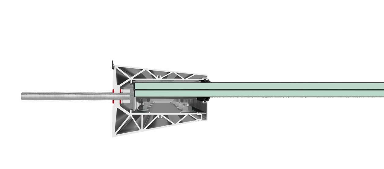
- Insert two pins (threaded rods) to hold the profile in place
ATTENTION: Ensure fastening on sturdy masonry
02. DRILLING THE WALL
Using the pre-drilled profile as a template, mark the position of the holes on the wall with the drill Then move the profile and drill the wall according to the marks made earlier. (Use 14 mm /0.55 in drill bit)
NB: Profiles are drilled with a 200 mm (7.87 in) pitch
03. CLEANING
Thoroughly clean the holes with a pump or compressed air before applying the chemical resin.
NB: Follow the instructions of the chemical anchor manufacturer
FORI Ø14 mm HOLES Ø14 mm Ø 0.55 in
04. APPLYING THE RESIN
Apply a certified chemical resin. Fill the hole to about half its depth.
NB: Follow the instructions of the chemical anchor manufacturer
It is recommended to use the gun with dispenser
05. INSERTING THE RODS
Insert the M12 threaded rods into the holes, leaving the necessary 28 mm (1.10 in) projection
06. PROFILE FIXING
Once the resin has dried, move the profile close and start fastening.
Insert in order:
1. Rubber washer
2. Linea Maxi Profile
3. Second rubber washer
4. Flat washer
5. Nut M12
(1.10 in)
07. INSERT PLASTICS FOR GLASS SUPPORT
1. Tighten nuts carefully
2. Insert the glass-holding plastics into the profile (4 pieces/meter)
3. Make sure you click the accessories into place
08. POSITIONING OF PLASTICS FOR GLASS SUPPORT
Distance the glass-holding plastics as shown in the diagram below.
The example shown represents a canopy on which a pane of glass with a width of 1 metre will be mounted.
For different widths please refer to the tables on pages 8-9
IMPORTANT: space required for the insertion of anti pull-out plastics
IMPORTANTE: spazio necessario per l’inserimento delle plastiche antisfilamento
Glass-holding plastic
09. RS SYSTEM ASSEMBLY
For installation in the 10+10 (3/8”+3/8”) glass profile, apply the supplied 4 mm black plastic snap-in shims (3 pieces/adjusting screw) to the R&S adjusting screw. In the case of 12+12 (1/2”+1/2”) glass, the adjusting screw is ready to use and does not require additional shims.
FOR 10+10 (3/8”+3/8”) GLASS
FOR 12+12 (1/2”+1/2”) GLASS
10. INSERTING THE “RS” SYSTEM
Insert the adjusting screws (“RS” system) into the profile, making sure to place them in the appropriate slots (4 pieces/metre).
ATTENTION:
Ensure that the flange nuts are flush with the head of the M10 screw before inserting the RS system into the profile
NO DISTANZA
NO DISTANCE
11. ANTI PULL OUT KIT
Take the packages of the anti pull out kits and prepare the components according to the glass to be used.
THE KIT CONTAINS:
- 1 anti-fall plastic piece with double-sided adhesive VHB (width 25 mm (0.98”) x length 100 mm (3.93”) - thickness 0.5 mm (0.01”)).
- 1 Stainless steel hexagon head bolt M10 x 16 (Maxi Linea with glass thickness 10+10 (3/8”+ 3/8”))
- 1 Stainless steel hexagon head bolt M10 x 12 (Maxi Linea with glass thickness 12+12 (1/2”+ 1/2”))
- 1 M10 Stainless steel flanged nut
ATTENTION:
Material valid for 1 metre. For larger widths see pages 8-9
USARE PER VETRO 10+10
USE FOR 10+10 (3/8”+3/8”) GLASS
USARE PER VETRO 12+12
USE FOR 12+12 (1/2”+1/2”) GLASS
VALID FOR BOTH GLASS SHIMS
VALIDO PER ENTRAMBE GLI SPESSORI VETRO
12. CLEANING THE GLUING AREA
First clean the area to be bonded with any neutral detergent. Carry out the operation near the corners where the plastic accessories will then be attached.
13. GLUING OF ACCESSORIES
Proceed with gluing the accessory by removing the tab shielding the doublesided adhesive tape. Take care to position the accessory close to the corners, flush with the glass as shown in the image.
RISPETTARE LA CORRETTA POSIZIONE DELL’ACCESSORIO, INSERIRE LA PARTE CON LA SCRITTA “LINEA MAXI” DAL LATO INTERNO
RESPECT THE CORRECT POSITION OF THE ACCESSORY, INSERT THE PART MARKED “LINEA MAXI” FROM THE INSIDE
IMPORTANTE:
IMPORTANT:
PRESTARE ATTENZIONE AD INCOLLARE IL PEZZO A FILO DEL BORDO VETRO
TAKE CARE TO GLUE THE PIECE FLUSH WITH THE GLASS EDGE
Linea Maxi
Linea Mini
ANTI PULL OUT KIT DIAGRAM
GLASS WIDTH
. OF ANTI PULL OUT ACCESSORIES up to 1,5 m (1.64 yd)
from 1,5 m up to 2,5 m (1.64 yd up to 2.73 yd)
from 2,5 m up to 3 m (2.73 yd up to 3.28 yd)
from 3 m up to 4 m (3.28 yd up to 4.37 yd)
SINGLE PANE
SINGLE PANE
SINGLE PANE
SINGLE PANE
SINGLE PANE
SINGLE PANE
SINGLE PANE
SINGLE PANE
SINGLE PANE
SINGLE PANE
SINGLE PANE
SINGLE PANE
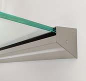
14. INSERTING THE GLASS
Insert the glass at an angle downwards.
GASKET ALREADY FITTED
GUARNIZIONE GIÀ MONTATA
15. GLASS SLOPE ADJUSTING SCREW
Adjust the slope of the glass using the front and rear nuts of the adjusting screws.
To move the pane upwards, turn the front nuts to the left and the rear nuts to the right. Proceed until the glass reaches the desired slope.
Conversely, to move the slope of the glass downwards, turn the rear nuts to the left, the front nuts to the right.
Once the desired slope has been found, tighten both rows of adjusting screws.
15 MM (0.59) SPANNER FOR THE ADJUSTING SCREW
TILT THE GLASS
INCLINARE IL VETRO
CHIAVE INGLESE DA 15 mm PER IL REGISTRO
VERSO IL BASSO
DOWNWARDS
16. PLUMB ALIGNMENT
Once the slope has been recorded, add threadlock to the bolts in the kit, which will then be used depending on the glass and canopy installed.
• 2 Stainless steel hexagon head bolts
M10 x 16 + 2 flanged nuts M10 (Maxi linea for glass 10+10 (3/8”+3/8”))
• 2 Stainless steel hexagon head bolts
M10 x 12 + 2 flanged nuts M10 (Maxi linea for glass 12+12 (1/2”+1/2”))
Tighten the bolts until you feel that all parts are under pressure. It is recommended not to force rotation by compromising the integrity of the plastic accessory.
ATTENTION:
Add threadlock Loctite 243 (or similar).
Bolt and nut included in the anti pull-out kit.
17. INSERT THE CLADDING
Once the glass has been levelled and the adjusting screws properly tightened, insert in the lower snap-fit cladding.
18. INSERTING THE CAPS
Screw on the side cover caps with the screws provided to complete the work
Finished.
Make sure you have followed all the steps.
“Good work”
SNAP-FIT CLADDING
CLADDING INSERTED
CARTER DA INSERIRE A SCATTO CARTER INSERITO
TAPPO LATERALE
SIDE CAP
LED CLADDING KIT INSTRUCTIONS
SETUP OF POWER CABLES
Arrange the corrugated cable with the power cables below the profile of the canopy and lead out the power cables.
CLADDING PREPARATION
Prepare the cladding before assembly on the profile Execute in order:
1. Cable feed hole
2. Gluing LED strip into the
3. Cable feed though the hole
4. Closure by plastic cladding
SPLICE THE CABLES
Splice the power supply cables with those of the LED strip
INSERT CLADDING WITH LED
Insert the snap-fit cladding onto the canopy
WE TAKE CARE OF YOUR PROJECTS
Our experience at your service. We guide you in choosing the best solution for your needs.
EXPERT GUIDE
Following a project through every stage is sometimes not easy. That is why we provide you with full support from technical advice through to post-purchase.
INSTALLATION
We select the experts who carry out the installation of our products to ensure the quality standard. During this phase, site tests are carried out to ensure that the installation has been carried out properly and that everything is safe.
How you can contact us:
email: faraone@faraone.it
Tel: +39 0861 784200
web: faraone.it
Request information through our website
FRANÇAIS NOTICE DE POSE
Modèle Linea Maxi
01. POSITIONNEMENT DE LA BARRE
- Positionner la barre - Faire le premier et le dernier trou - Insérer deux goupilles (tiges filetées) pour maintenir le profil en place
ATTENTION :
Vérifier d’avoir effectué la fixation sur une maçonnerie solide
02. PERFORATION DU MUR
En utilisant le profilé déjà percé comme gabarit, marquer la position des trous sur le mur à l’aide d’une perceuse. Déplacer ensuite le profilé et perforer le mur en fonction des marques faites précédemment.
(Utiliser un foret de 14 mm)
N.B. : Les profils sont percés au pas de 200 mm
03. NETTOYAGE
Nettoyer soigneusement les trous à l’aide d’une pompe ou d’air comprimé avant d’appliquer la résine chimique.
NB : Suivre les instructions du fabricant de chevilles chimiques
FORI Ø14 mm TROUS Ø14 mm
04. APPLICATION DE LA RÉSINE
Appliquer une résine chimique certifiée. Remplir le trou jusqu’à la moitié de sa profondeur.
N.B. : Suivre les instructions du fabricant de chevilles chimiques
Il est recommandé d’utiliser un pistolet doté d’un doseur
05. INSERTION DES TIGES
Insérer les tiges filetées M12 dans les trous, en laissant une saillie de 28 mm
06. FIXATION DU PROFILÉ
Une fois la résine séchée, rapprocher le profilé et procéder à la fixation.
Insérer dans l’ordre :
1. Rondelle en caoutchouc
2. Profilé Linea Maxi
3. Deuxième rondelle en caoutchouc
4. Rondelle plate
5. Écrou M12
07. INSÉRER LES PIÈCES EN PLASTIQUE POUR SUPPORT DU VERRE
1. Serrer les écrous avec précision
2. Insérer les plastiques porte-verre dans le profilé (4 pièces/mètre)
3. Veiller à ce que les accessoires soient bien enclenchés (clic) dans leur logement
08. POSITIONNEMENT DES PIÈCES EN PLASTIQUE POUR LE SUPPORT DU VERRE
Espacer les plastiques porte-verre comme indiqué dans le schéma ci-dessous.
L’exemple illustré représente un auvent sur lequel sera montée une plaque en verre d’une largeur de 1 mètre.
Pour les différentes largeurs, consulter les tableaux des pages 24-25.
IMPORTANTE: spazio necessario per l’inserimento delle plastiche antisfilamento
IMPORTANT: espace nécessaire pour l’insertion des plastiques anti-arrachement
Verre
Plastica poggia-vetro
Plastique repose-verre
09. ASSEMBLAGE DU SYSTÈME RS
Pour l’installation dans le profilé du verre 10+10 , appliquer sur le registre R&S les cales à enclenchement de 4 mm en plastique noir fournies (3 pièces/registre).
Dans le cas d’un verre 12+12, le registre est prêt à l’emploi et ne nécessite pas de cales supplémentaires.
POUR VERRE 10+10
POUR VERRE 12+12
SENZA SPESSORI
CALES
10. INSÉRER LE SYSTÈME « RS »
Insérer les registres (système « RS ») dans le profilé, en veillant à les placer dans les fentes appropriées (4 pièces/mètre).
ATTENTION :
Veiller à ce que les écrous à bride soient en butée avec la tête de la vis M10 avant d’insérer le système RS dans le profilé
NO DISTANZA
11. KIT ANTI-ARRACHEMENT
Prendre les emballages des kits anti-arrachement et préparer les composants en fonction du verre à utiliser.
LE KIT CONTIENT
:
- 1 pièce plastique antichute avec adhésif double face VHB (largeur 25 mm x longueur 100 mm - épaisseur 0.5 mm).
- 1 boulon à tête hexagonale M10 x 16 Inox (Linea Maxi avec épaisseur de verre 10+10)
- 1 boulon à tête hexagonale M10 x 12 Inox (Linea Maxi avec épaisseur de verre 12+12)
- 1 écrou à bride M10 en acier inoxydable
ATTENTION :
Matériel valable pour 1 mètre. Pour des largeurs plus importantes, voir pages 24-25
USARE PER VETRO 10+10
USARE PER VETRO 12+12
PAS DE DISTANCE À UTILISER POUR LE VERRE 10+10 À UTILISER POUR LE VERRE 12+12
VALABLE POUR LES DEUX ÉPAISSEURS DE VERRE
VALIDO PER ENTRAMBE GLI SPESSORI VETRO
12. NETTOYAGE DE LA ZONE DE COLLAGE
Nettoyer d’abord la zone à coller avec un détergent neutre. Effectuer l’opération à proximité des coins où les accessoires en plastique seront ensuite fixés.
13. COLLAGE DES ACCESSOIRES
Procéder au collage de l’accessoire en retirant la languette protégeant le ruban adhésif double face. Veiller à positionner l’accessoire à proximité des coins, au ras du verre, comme indiqué sur l’illustration.
RESPECTER LA POSITION CORRECTE DE L’ACCESSOIRE, INSÉRER LA PARTIE MARQUÉE « LINEA MAXI » DE L’INTÉRIEUR
RISPETTARE LA CORRETTA POSIZIONE DELL’ACCESSORIO, INSERIRE LA PARTE CON LA SCRITTA “LINEA MAXI” DAL LATO INTERNO
100
IMPORTANTE: PRESTARE ATTENZIONE AD INCOLLARE IL PEZZO A FILO DEL BORDO VETRO
IMPORTANT : VEILLER À COLLER LA PIÈCE AU RAS DU BORD DU VERRE
Linea Maxi
Linea Mini
SCHÉMA DU KIT ANTI-ARRACHEMENT
LARGEUR DU VERRE NOMBRE D’ACCESSOIRES ANTI-ARRACHEMENT
jusqu’à 1,5 m
de 1,5 m jusqu’à 2,5 m
de 2,5 m jusqu’à 3 m
de 3 m jusqu’à 4 m
PLAQUE UNIQUE
UNIQUE
PLAQUE UNIQUE PLAQUE UNIQUE
PLAQUE UNIQUE
PLAQUE UNIQUE
PLAQUE UNIQUE
PLAQUE UNIQUE
PLAQUE UNIQUE
PLAQUE UNIQUE
PLAQUE UNIQUE
PLAQUE UNIQUE
PLAQUE UNIQUE
PLAQUE UNIQUE
PLAQUE UNIQUE
PLAQUE UNIQUE
14. INSÉRER LE VERRE
Insérer le verre en l’inclinant vers le bas.
JOINT DÉJÀ MONTÉ
GUARNIZIONE GIÀ MONTATA
15. REGISTRE DE LA PENTE DU VERRE
Régler la pente du verre à l’aide des écrous avant et arrière des registres. Pour déplacer la plaque vers le haut, tourner les écrous avant vers la gauche et les écrous arrière vers la droite. Procéder ainsi jusqu’à ce que le verre atteigne la pente souhaitée.
Inversement, pour déplacer la pente du verre vers le bas, tourner les écrous arrière vers la gauche, les écrous avant vers la droite.
Une fois la pente souhaitée trouvée, serrer les deux rangées de registres.
CLÉ ANGLAISE DE 15 MM POUR LE REGISTRE
INCLINER LE VERRE
INCLINARE IL VETRO
CHIAVE INGLESE DA 15 mm PER IL REGISTRO
VERSO IL BASSO
VERS LE BAS
16. NIVELLEMENT
Une fois la pente enregistrée, ajouter du frein-filet sur les boulons du kit, qui seront ensuite utilisés en fonction du verre et de l’auvent installés.
- 2 boulons à tête hexagonale M10 x 16
Inox + 2 écrous à bride M10 (Linea Maxi pour verre 10+10)
-2 boulons à tête hexagonale M10 x 12
Inox + 2 écrous à bride M10 (Ligne Maxi pour verre 12+12)
Serrer les boulons jusqu’à entendre que toutes les pièces sont sous pression. Il est recommandé de ne pas forcer la rotation en compromettant l’intégrité de l’accessoire en plastique.
ATTENTION :
Ajouter du frein-filet Loctite 243 (ou similaire).
Boulon et écrou inclus dans le kit anti-arrachement.
17. INSÉRER LE PARCLOSE
Une fois que les verres ont été nivelés et que les registres ont été correctement serrés, insérer le parclose inférieur à enclenchement.
18. INSÉRER LES EMBOUTS
Visser les embouts latéraux à l’aide des vis fournies pour terminer le travail
Fini.
S’assurer d’avoir suivi toutes les étapes.
« Excellent travail »
PARCLOSE À INSÉRER À ENCLENCHEMENT
CARTER DA INSERIRE A SCATTO
CARTER INSERITO
PARCLOSE INSÉRÉ
INSTRUCTIONS POUR LE KIT PARCLOSE LED
PRÉPARATION DES CÂBLES
D’ALIMENTATION
Disposer le conduit ondulé avec les câbles d’alimentation sous le profilé de l’auvent et faire sortir les câbles d’alimentation.
PRÉPARATION DU PARCLOSE
Préparer le parclose avant le montage sur le profilé
Exécuter dans l’ordre :
1. Trou de passage des câbles
2. Collage des bandes de LED dans le
3. Passage des câbles à travers le trou
4. Fermeture par parclose plastique
FORARE
PERFORER
JOINDRE LES CÂBLES
Joindre les câbles d’alimentation à ceux de la bande LED
INSÉRER LE PARCLOSE AVEC LED
Insérer le parclose à enclenchement sur le profilé de l’auvent
NOUS PRENONS EN CHARGE VOS PROJETS
Notre expérience à votre service. Nous vous guidons dans le choix de la meilleure solution pour vos besoins.
GUIDE D’EXPERT
Il n’est pas toujours évident de suivre un projet dans toutes ses phases. C’est pourquoi nous vous offrons une assistance complète, depuis les conseils techniques jusqu’à l’aprèsvente.
INSTALLATION
Nous sélectionnons les experts qui effectuent l’installation de nos produits afin de garantir le niveau de qualité. Au cours de cette phase, des tests sont effectués sur site pour garantir que l’installation a été réalisée dans les règles de l’art et que tout est sécurisé.