ASSEMBLY INSTRUCTIONS
NOTICE DE POSE
Ninfa 56 Model / Modèle Ninfa 56


Ninfa 56 Model / Modèle Ninfa 56
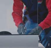
- Place the bar
- Make the first and last hole
- Insert two bolts (threaded rods supplied) to keep the profile in position
IMPORTANT:
Make sure that the fixing is done on solid masonry
EXTERNAL SIDE
Using the pre-drilled profile as a template, mark the position of the holes on the floor with the drill. Then move the profile and drill the floor according to the marks previously made. (Use a 12 mm / 0.47” bit)
Note. The profiles are drilled within a 200 mm (7.87”) hole-to-hole distance
Clean carefully the holes using a special blower, or with compressed air, before applying the chemical resin.
Note: Follow the manufacturer’s instructions regarding the chemical anchor
EXTERNAL SIDE
Apply the certified chemical resin. Fill the hole about half of its depth.
It is recommended to use the dispenser gun
Insert the M10x130/5.11” threaded rods into the holes leaving the required 23 mm (0.90”) protrusion for the profile thickness and the M10 nuts
When the resin has dried, proceed with the installation.
Insert as follows:
1. Rubber washer
2. Ninfa 56 profile
3. Second rubber washer
4. Flat washer
5. M10 nut
Note: Ensure that the Ninfa profile adheres to the floor or the load-bearing structure (concrete, steel, etc.).
To meet the tightening torque, follow the manufacturer’s instructions for the chemical anchor.
SECTIONAL PROFILE VIEW
Ninfa 56 Assembly instructions
Assembly and installation of the adjusters and glass-holding plastic
FOR 6+6 (1/4”+ 1/4”) GLASS
1/4”+ 1/4”
FOR 8+8 (5/16”+ 5/16”) GLASS
SPESSORI DA 4 mm
SPACERS 4 mm (0.15”)
5/16”+5/16”
Tighten carefully the nuts and insert the glass-holding plastic into the profile (4 pieces/meter) (4 pieces/3.28ft)
Space the glass-holding plastic as shown in the attached diagram.
The example is on a 1 meter (3.28ft) long balustrade
Glass-holding plastic
Insert the glass in an inwards inclined position, taking care not to touch (twist) the external gasket.
IMPORTANT:
Place the glass slowly into the profile (a sudden drop of the glass would risk breaking the polycarbonate spacers)
The tempered-hardened glass must be positioned with the hardened sheet facing the external side.
Insert the adjusters (“RS” system) for adjusting the vertical plumb of the glass in correspondence with the glass-holding plastic.
First insert one of the two central adjusters, proceed with the vertical plumb of the glass and then insert the remaining adjusters to complete the adjustment. (4 for each meter/3.28ft)
ATTENTION:
Make sure that the flanged nuts are in contact with the head of the M8 screw and are facing the profile
Gasket already mounted
Inclinare il vetro
Incline the glass Glass
By orienting the glass plate manually, reach the vertical plumb and consequently tighten the two lower screws and the upper one of the central adjuster, constantly checking the bubble level.
Note: an excessive tightening of the adjusters can lead to the opening of the profile and, consequently, to the malfunction of the adjusters.
ATTENTION:
To tighten the adjusters, it is recommended to use a torque wrench with a tightening torque set from 5 Nm.
Ninfa 56 Assembly instructions
Check the vertical plumb of the glass with the bubble level. If it is not level, proceed as follows:
Adjust the inclination of the glass by using the upper and lower screws of the adjusters.
To move the glass plate outwards, rotate the lower nuts clockwise; vice versa, rotate the upper nuts counterclockwise until the glass is plumb.
Conversely, to move the glass plate inwards, rotate the upper nuts clockwise; vice versa, rotate the lower nuts counterclockwise.
At this point, having found the required inclination, tighten both rows of adjusters.
Outwards
Chiave inglese da 13 mm per il registro
13 mm (0.51”) wrench for the adjusting
Inwards
13 mm (0.51”) wrench for the adjusting
Chiave inglese da 13 mm per il registro
Tutti i registri inseriti
All adjusters are inserted
The adhesive gasket provided in the package is suitable for the height of the Ninfa profile and the thickness of the glass.
Position the adhesive gasket on the glass after inserting it into the profile, then follow the installation instructions starting from step 11
ATTENTION:
Align the gasket with the reference line
After positioning the first glass panel, repeat the same installation steps with the next glass panel, making sure to push the second glass panel against the gasket until it is compressed by approximately 1mm (0.03”)
N.B.
Note:
Applicare la guarnizione adesiva a filo carter esterno
Apply the adhesive gasket flush with the outer cladding
16.
Proceed as follows:
1. Approach the profiles
2. Position the joint strip from above
3. Screw the joint strip with the self-drilling screws that are in the KIT
4. Insert the snap-fit cladding from above
It is valid for all Ninfa models.
Proceed as follows:
1. Approach the profiles
2. Position the joint bracket from above
3. Screw the joint bracket with the self-drilling screws that are in the KIT
4. Insert the snap-fit cladding from above
It is valid for all Ninfa models.
When the glass plates are vertically plumb and the adjusters have been properly tightened, insert the snap-fit upper cladding.
Carter da inserire a scatto
Cladding to be inserted by snap shut
Cladding inserted
Screw the side-covering caps with the supplied screws to complete the job.
Finished.
Make sure you have properly followed all the steps.
“Good job!”
When all the glass plates have been positioned, insert the internal snap-fit cladding and then seal well between glass and glass above the gasket.
Use only neutral black silicone.
Cladding to be inserted by snap shut
Tappo profilo Ninfa Sigillare inizio e fine dopo aver messo il tappo
profile cap Seal at the beginning and at the end after inserting the cap
Our
experience at your service.
We guide you in choosing the best solution for your needs.
Following a project through every stage is sometimes not easy. That is why we provide you with full support from technical advice through to post-purchase.

We select the experts who carry out the installation of our products to ensure the quality standard. During this phase, site tests can be carried out to ensure that the installation has been carried out properly and that everything is safe.
How you can contact us:
email: faraone@faraone.it
Tel: +39 0861 784200
web: faraone.it | faraone-parapetti.it

Request information through our website

THE GLASS BALUSTRADE WITH ULTRA SLIM DESIGN
THE GLASS BALUSTRADE WITH ULTRA SLIM DESIGN
- Placez la barre
- Faites le premier et le dernier trou
- Insérer deux goupilles (tiges filetées fournies) pour maintenir le profil en position
IMPORTANT :
Assurez-vous que la fixation est faite sur de la maçonnerie solide
CÔTÉ EXTÉRIEUR
En utilisant le profil déjà percé comme gabarit, marquez la position des trous sur le sol avec la perceuse. Déplacez ensuite le profil et percez la dalle à l’endroit des repères précédemment réalisés.
(Utilisez une mèche diamètre 12 mm)
Note : Les profils sont percés tous les 200 mm
Nettoyer soigneusement les trous à l’aide d’une soufflette spéciale, ou à l’air comprimé, avant d’appliquer la résine chimique.
Note : Suivre les instructions du fabricant de l’ancrage chimique
CÔTÉ EXTÉRIEUR
FORI Ø12 mm
TROUS Ø12 mm
Appliquez la résine chimique certifiée. Remplissez le trou à environ la moitié de sa profondeur.
Il est recommandé d’utiliser le pistolet avec doseur
05. INSERTION DES TIGES
Insérez les tiges filetées M10x130 dans les trous en laissant le dépassement de 23 mm requis pour l’épaisseur du profil et les écrous M10
06. FIXATION DU PROFIL
Lorsque la résine a séché, procédez à l’installation.
Suivez l’ordre qui suit :
1. Rondelle en caoutchouc
2. Profil Ninfa 56
3. Deuxième joint en caoutchouc
4. Rondelle plate
5. Écrou M10
Note : Assurez-vous que le profil Ninfa soit bien fixé au sol ou à la structure porteuse (béton, acier, etc.)
Pour respecter le couple de serrage, suivez les instructions du fabricant de l’ancrage chimique.
RÉSINE
CHIMIQUE
COUPE DU PROFIL
Couplage d’angle : solutions aux p. 26-27
Préparation et installation du systèmes de réglage et les systèmes d’appui et calage extérieur
VERRE ép 6+6 (cales de 4 mm)
6+6
VERRE ép 8+8 (pas de cale à prévoir)
8+8
SPESSORI DA 4 mm
ÉPAISSEUR DE 4 mm
SANS ÉPAISSEUR
Serrez soigneusement les écrous et insérez dans le profil les systèmes d’appui et calage extérieur (4 pièces/mètre)
Calez les systèmes d’appui et calage extérieur comme indiqué dans le schéma joint.
L’exemple concerne une balustrade d’1 mètre de longueur.
Plastica poggia-vetro Système de réglage
10. POSITIONNEMENT DU VERRE
Insérez le verre dans une position inclinée vers l’intérieur, en prenant soin de ne pas frotter le joint extérieur.
IMPORTANT :
Placez délicatement le verre dans le profil (une chute du verre risquerait de casser les cales en polycarbonate).
Le verre trempé doit être positionné avec la plaque trempée vers l’extérieur.
Profilo
Placez les systèmes de réglage du verre en le clipsant sur les cales inférieures.
Insérez d’abord l’un des deux régleurs centraux, procédez à l’aplomb vertical du verre puis insérez les régleurs restants pour terminer le réglage. (4 pour chaque mètre)
Inclinez le verre
Inclinare il vetro
ATTENTION :
Assurez-vous que les écrous à bride sont en contact avec la tête de la vis M8 et face au profil
1000
Vetro
Guarnizione già montate
Les joints sons déjà en place
En orientant manuellement le panneau de verre, atteindre le niveau de mise à plomb et par conséquent serrez les vis inférieures et supérieures du système de réglage au centre du panneau de verre, en vérifiant constamment le niveau de la bulle.
Note : Un serrage excessif des écrous peut entraîner l’ouverture du profil et, par conséquent, le dysfonctionnement du système.
ATTENTION :
Pour le serrage des réglages, il est recommandé d’utiliser une clé dynamométrique réglée sur un couple de serrage de 5 Nm.
Réglage du verre et schéma de montage du joint entre les vitres
Vérifiez la mise à plomb du verre avec le niveau, puis réglez l’inclinaison du verre en utilisant les vis des réglages inférieures et supérieures.
Pour pousser le panneau vers l’extérieur, desserrez les vis inférieures et serrez les vis supérieures, jusqu’à ce que le verre soit à plomb.
À l’envers, pour pousser le verre vers l’intérieur, desserrez les vis supérieures et serrez les vis inférieures.
Quand vous avez trouvé l’inclinaison souhaitée, serrez les deux rangées de réglages.
Verso l'esterno
Vers l’extérieur
Chiave inglese da 13 mm per il registro
Clé de 13 mm pour le réglage
Vers l’intérieur
Verso l'interno
Clé de 13 mm pour le réglage
Chiave inglese da 13 mm per il registro
Tutti i registri inseriti
Tous les régleurs sont insérés
La mousse adhésif fourni dans le colis est adapté à la hauteur du profil Ninfa et à l’épaisseur du verre.
Collez le joint-mousse sur le verre, après l’avoir inséré dans le profil, puis procédez avec les panneaux suivants (Notice de pose à partir de point 11).
ATTENTION :
Alignez le joint avec la ligne de référence
N.B.
Note:
Fixez le joint au raz de la face supérieure
Applicare la guarnizione adesiva a filo carter esterno
Après avoir disposé le premier panneau de verre, répétez la même séquence de montage avec le suivant en prenant soin de pousser le deuxième panneau de verre contre le joint jusqu’à ce qu’il soit pressé d’environ 1 mm.
Procédez dans l’ordre suivant :
1. Approchez les profils
2. Positionnez le connecteur par le haut
3. Vissez le connecteur avec les vis auto-perceuses
4. Installez la parclose à pression
Adapté pour tous les modèles Ninfa
Procédez dans l’ordre suivant :
1. Approchez les profils
2. Positionnez le connecteur par le haut
3. Vissez le connecteur avec les vis auto-perceuses
4. Installez la parclose à pression
Adapté pour tous les modèles Ninfa
18. INSTALLER LA PARCLOSE
Quand le verre est mis à plomb et les écrous sont bien serrés, insérez à pression la parclose supérieure.
Parclose à pression
Carter da inserire a scatto
Attachez les embouts latéraux avec les vis fournies pour terminer la pose.
Fini.
Vérifiez si vous avez suivi les instructions correctement.
« Bon travail ! »
Embout latéral
Tappo laterale
Carter inserito
Parclose posée
Une fois que tous les panneaux de verre ont été positionnés, insérez le carter intérieur à encliqueter, puis scellez soigneusement entre les panneaux de verre au-dessus du joint. Utilisez uniquement du silicone neutre de couleur noire.
Carter à insérer par encliquetage
Carter da inserire a scatto
Guarnizione
Joint
Tappo profilo Ninfa
Embout du profil Ninfa
Sigillare inizio e fine dopo aver messo il tappo
Scellez au début et à la fin après avoir inséré l’embout.
Notre expérience à votre service. Nous vous guidons dans le choix de la meilleure solution pour vos besoins.
GUIDE D’EXPERT
Il n’est pas toujours évident de suivre un projet dans toutes ses phases. C’est pourquoi nous vous offrons une assistance complète, depuis les conseils techniques jusqu’à l’aprèsvente.
Nous sélectionnons les experts qui effectuent l’installation de nos produits afin de garantir le niveau de qualité. Au cours de cette phase, des tests sont effectués sur site pour garantir que l’installation a été réalisée dans les règles de l’art et que tout est sécurisé.
Contacts :
email : faraone@faraone.it
Tel : +39 0861 784200
web : faraone.it | faraone-parapetti.it
Demande d’informations via notre site web