

Research-and-production
INSTRUCTION MANUAL SPRUT – 00.00 IM
company “Factor” DRY POWDER FIRE-EXTINGUISHING MODULE SPRUT
These instruction manual is intended for study of the material parts of dry powder firefighting modules SPRUT (hereinafter referred to as modules), rules of their use, mounting, exploitation and maintenance.
1. GENERAL INFORMATION ABOUT THE PRODUCT
1. Product marking
Modules have next marking structure:
SPRUT – XXxx – XX – XX – TS
(1) (2) (3) (4) (5) (6) where (1) – product name;
2 – nominal mass of fire extinguishing powder charge in kg;
3 – marking of extinguishing method and variant of module installation;
4
embodiment marking – kitting variant (for modules, intended for use as a part of automatic fire-extinguishing systems (base modification) these fields are not filled in);
5 – nominal operating temperature of module locking and spray-type device;
6 – technical specifications (TS) marking (ТУ У 29.2-13672801-003:2011)
1.2. Specifics of construction and use
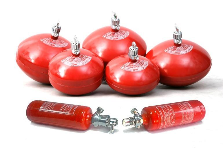
SPRUT modules are produced in six dimension-types – with extinguishing powder charge (hereinafter referred to as EP) with nominal mass of 1, 3, 6, 9, 12 and 15 kg.
Depending on locking and spray-type device construction (hereinafter referred to as LSTD), which provides distribution of extinguishing powder in protected zone, modules have two base modifications
SPRUT(v) (СПРУТ(о)) and SPRUT(s) (СПРУТ(п)). Modules of base modifications V and S (SPRUT -1v, SPRUT -1s, SPRUT -3v, SPRUT -3s, SPRUT -6v, SPRUT -6s, SPRUT -9v, SPRUT -9s, SPRUT -12v, SPRUT -12s, SPRUT -15v, SPRUT -15s), according to ДСТУ3972-2000, by their inertia belong to fast-acting fire-extinguishing systems, by duration of EP feeding – SPRUT-1 modules are impulse action modules (duration of EP feeding is up to 0,5 s), and other dimension-types – are brief action modules (duration of EP feeding is from 1,2 up to 5 s). SPRUT(v) modules predominantly provide volume fireextinguishing method, and SPRUT(s) predominantly provide surface fire-extinguishing method. These modules are intended for use as a part of automatic fire-extinguishing systems.
For autonomous fire-extinguishing 01 and 02 embodiment modules should be used, both base modifications, that are different in that 01 doesn’t have electromechanical actuator (EMA), but pressure signaling device (PSD) is built-in, and in the case of 02 modification both electromechanical actuator and pressure signaling device are absent. For example, SPRUT-9v-01 or SPRUT-12s-02, Modules of listed embodiments mostly are mounted on the ceilings.
In order to provide the possibility of mounting modules on the walls or other vertical structures of the secured room, the wall is additionally provided. In the designation of the modules of this implementation, the letter "w" («н») is added, for example, SPRUT-3vw, SPRUT-9sw-01, SPRUT-15vw-02, etc.
The nominal operating temperature of the LSTD modules can be 68°C or 93°C
The developer and supplier of modules – LLC "RPF "Factor", Kyiv,phone (044)338-50-27, 338-50-16.
Manufacturers of modules:
DTGO "South-Western Railway" (specialized section of fire-protection works (SDPR) of the Kiev detachment of departmental paramilitary protection);
The number of technical specifications of TУ У 29.2-13672801-003:2011
- 2 -
–
–
2. DESCRIPTION AND OPERATION OF PRODUCT
2.1. Product function
2.1.1. Modules can be used for extinguishing class A fire (solid substances burning), class B (liquid substances burning), class C (gas burning) in accordance with ДСТУ EN-2 and electrical equipment, that is under voltage up to 36 kV.
2.1.2. Modules can be used for protection of different objects, providing realization of different fire-extinguishing methods:
- volumetric; local volumetric;
- surface; local surface;
2.1.3. Modules of both base modifications SPRUT-1v, SPRUT-1s, SPRUT-3v, SPRUT-3s, SPRUT-6v, SPRUT-6s, SPRUT-9v, SPRUT-9s, SPRUT-12v, SPRUT-12s, SPRUT-15v, SPRUT-15s, independently of the variant of their mounting, are intended for usage as a part of fast-acting automatic fire-extinguishing systems (inertia up to 1 s) and trigger under the action of initial signal from fire-control unit. Starting current is not less than 200 mA, at the voltage on the electro mechanical stimulus contacts not less than 2 V. Let-go current for check of electric starting circle is not more than 10mA. Modules will also trigger in the case of temperature increasing in the protected premise higher than operating temperature of heat-sensitive bulb in modules LSTD (68 C or 93 C).
For guaranteeing modules functioning as a part of automatic fire-extinguishing systems, it is necessary to use fire alarm control panels that provide above mentioned parameters of electric signal for control and start, and accordance with ДСТУ EN 54-2:2003 (EN 54-2:1997, ІDТ) requirements.
2.1.4. Modules of 01 and 02 embodiments are intended for use as autonomous fireextinguishing device and trigger only under the action of increases temperature, which is generated by originated fire. These modules of autonomous fire-extinguishing can be used for protection of explosive and fire hazardous and fire-hazardous premises of categories А, Б, В, area and volume of which is not higher than “protected area” and “protected volume” values of corresponding module.
2.1.5. Modules’ embodiments envisage their mounting both on the ceiling of protected premise and on the walls and vertical surfaces using brackets that are included in the module set, or on special brackets.
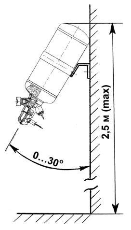
SPRUT-1 modules of both base modifications are allowed to mount under the angle of 30 degrees relatively to vertical surface. These modules are intended for protection of relatively small by volume and/or area objects (electric box, cable tunnels, painting cameras, engine compartments on mobile and immobile transport, safes, etc).
2.1.6. Modules are not intended for work in environments that contain caustic gases or vapors in concentrations that cause destruction of metals.
2.1.7 It is allowed to mount modules outside the premise with placement category 3 in accordance with ГОСТ 15150 for operation under environmental temperature from -20 C up to -60 C.
2.1.8. Compressed air can be used as working gas in modules (not higher than 9 pollution class in accordance with ГОСТ 17433), or gaseous nitrogen (of the highest or first sort in accordance with ГОСТ 9293), or gaseous carbon dioxide (of the highest or first sort in accordance with ГОСТ 8050).
- 3 -
2.1.9. Dew point temperature of working gas needs to be not higher than -25 C.
2.2. Device composition, structure and principle of operation
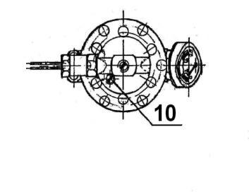
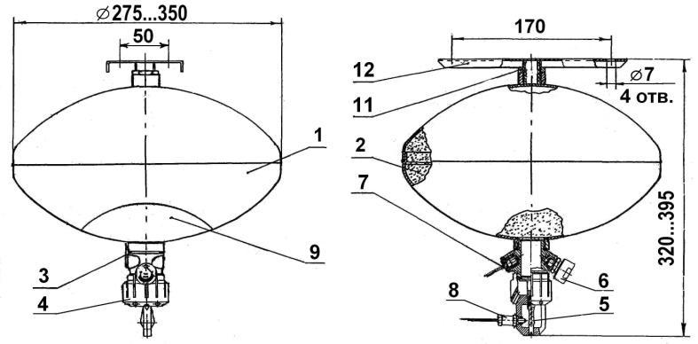
General view of base modifications modules (SPRUT-1v, SPRUT-1s, SPRUT-3v, SPRUT3s, SPRUT-6v, SPRUT-6s, SPRUT-9v, SPRUT-9s, SPRUT-12v, SPRUT-12s, SPRUT-15v, SPRUT-15s) is given on fig. 1. Modules consist of ellipsoid form vessel 1 with charge EP 2, which is under pressure of working gas 1,4 MPa (14 kgs/cm-2). Locking spray-type device 3 (constructive variants LSTDv or LSTDs) is installed in opening of the vessel. LSTD includes sprayer 4 (correspondingly combined and jet-stream; on fig 1. – combined) with heat lock in the form of glass bulb 5, pressure indicator 6 and pressure signaling device 7. Electromechanical actuator 8 is installed on sprayer 4, it is connected with control panel. The marking accordingly to normative requirements is marked on label 9. Block-screw 10 is mounted in LSTDv or LSTDs in order to prevent unauthorized triggering during transportation or mounting. After mounting the module, block-screw is deleted. Threaded connecting pipe 11 is welded to the vessel for connection with bracket 12, which is fixed on the ceiling of protected premise or on other horizontal construction with the help of four screws (dowels).
Fig.
General view of SPRUT modules of base modification
charge of fire-extinguishing powder from 3 up to 15 kg: 1 – vessel; 2 – fire-extinguishing powder; 3 – locking and spray-type device; 4 – combined nozzle; 5 – glass bulb; 6 – indicator; 7 – pressure signaling device; 8 – electromechanical actuator; 9 – label; 10 – block-screw; 11 – connecting pipe; 12 – bracket
- 4 –
Вид А А
1.
“v”(“o”) and “s”(“п”) with
For charging the module with compressed gas, and also its unloading, the check valve is installed on locking spray-type device. The valve is situated under indicator 6.
Indicator 6 is intended for visual control of the pressure in module during exploitation.
Pressure signaling device 7 is connected with fire control alarm panel and allows to control pressure in module during maintenance standby mode, and when module triggers, it gives corresponding signal.
Electromechanical actuator (EMA) allows to start the module by signal from control panel triggering inertia of the module is not higher than 0,1 second.
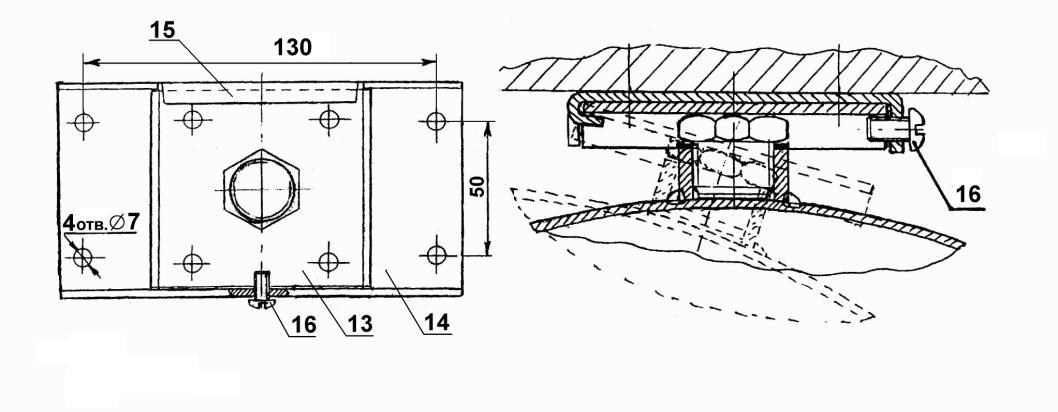
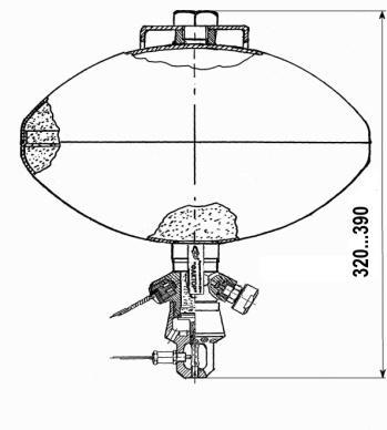
Figure 2 illustrates mounting variant of modules using modified bracket 13 and platform 14 with holder 15 and check screw 16. Using this constructive variant provides more comfortable modules mounting on the ceiling, especially for dimension-types and EP charge of 9 kg and more. At that, the platform is firstly attached to the ceiling, and bracket 13 is twisted in the connecting pipe 11 (fig. 1). Module with the bracket installed on the platform 14, using holder 15 and check screw 16. For mounting modules SPRUT-3 and SPRUT-6 only usage of bracket 13 is possible.
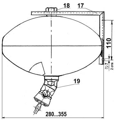
Illustrates general view of base modification SPRUT modules for mounting on the wall. For their mounting on vertical surface the bracket 17 and screw 18 are used. For providing effective distribution of fire-extinguishing powder in protected zone, which is given from the module of this construction, the angle bar 19 is mounted in inlet of the vessel, with 45 angle, to which LSTD is connected
Fig.
- 5-
Fig.2. Mounting variant of modules using modified bracket 13 – bracket; 14 – platform with holder 15; 16 – check screw
3.
Fig.
modules
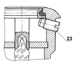
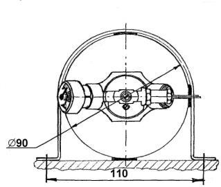
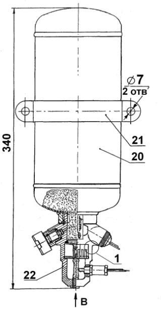
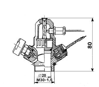
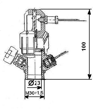
modifications. In contrast to modules mentioned above, vessel 20 of these modules have cylindrical form, and collar 21 is used for their mounting on constructive elements of protected object. Besides, LSTD with nozzle 22 is used in SPRUT-1v modules, which construction differs from combined nozzle that are used in other SPRUT modules, designed for realization of volume fire-extinguishing method. Block-screw 23 construction and the place of its mounting also differ from modules of other dimension-types.
- 6 -
Fig. 3. General view of base modification modules “vw”(«он») and “sw”(«пн») in onthe-wall mounting variant
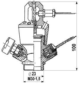
View В _ 1 _
4. Illustrates general view of
SPRUT-1v and SPRUT-1s base
Fig. 4. General view of SPRUT-1v modules
а) LSTD for realization of volumetric fire-extinguishing ,method using SPRUT-3v, SPRUT-6v, SPRUT-9v, SPRUT-12v, SPRUT-15v modules;
b) LSTD for realization of volumetric fire-extinguishing method using SPRUT-1v modules;
c) LSTD for realization of surface fire-extinguishing method using SPRUT modules of all dimension-types.
Modules operate in the following way.
In automatic mode (only base modifications modules, fig. 1), after receiving the signal from fire signaling device on the fire alarm control panel, it sends electric impulse to electro mechanical stimulus 8, which coupling rod moves to mechanical contact with glass thermal retort 5, and destroying it. After that LSTD valve opens and fore-extinguishing powder, under the action of working gas in the module, is dispersed inside the protected zone and provides fire elimination.
When pressure in module decreases, pressure signaling device 7 sends single to the control alarm panel about the module triggering.
In autonomous mode (embodiments 01 and 02), when fire originates and the temperature increases in the protected premise higher than temperature of heat-sensitive retort triggering (68 C or 93 C), the last one is destroyed, LSTD valve opens and fire-extinguishing powder under the action of working gas pressure is dispersed in the protected zone and provides fire elimination.
In modules of 01 embodiment the pressure signaling device 7 informs about its triggering. Modules of 02 embodiment don’t send information about triggering
2.3. Technical characteristics
Main technical characteristics of modules for corresponding embodiments are given in table 1.
- 7 -
Fig. 5 illustrates general view of locking spray-type devices, with which SPRUT modules are equipped.
а) b) c)
Fig. 5. General view of SPRUT modules LSTD
Table 1 – Main technical characteristics of SPRUT modules
- 8 -
Name of the characteristic SPRUT1v SPRUT-1s SPRUT-3v SPRUT-3vw SPRUT-3s SPRUT-3sw 1. Capacity of module vessel, l 1,3 -0,05 1,3 -0,05 6,0 -1,5 6,0 -1,5 2. Mark of fire-extinguishing powder (DPEC) FACTOR АВС-40 ТУ У 24.6-13672801-004-2004 3. Mass of charge DPEC, kg 1,00 +0,05 1,00 +0,05 3,00 +0,1 3,00 +0,1 4. Constructive mass of module, kg, not more than 1,3 1,3 3,5 3,5 5. Full mass of module 2,35 2,35 6,6 6,6 6. Operating temperature of the module, C 68 3% or 93 3% 7. Module inertia from the action of electric starting signal, c, not more than 1,0 8. Minimal voltage of starting signal on the stimulus contacts, V, not less than 2,0 9, Amplitude of direct current when starting the module, mA, not less than 200 10. Let-go current of check the circle of electric starting, mA, not more than 10
Voltage in electric circle of signaling device, V 12 +1,2 12. Direct current in electric circle of pressure signal device power supply, A From 0,1 up to 0,5 13. Dew point of working gas, C, not higher than -25 that corresponds volumetric part of water vapor 0,062% 14. Working gas pressure in the module vessel under temperature 20 C, MPa (kgs/cm-2) 1,4 0 +0,05 (14 0 +0,5) 15. Duration of fire-extinguishing powder feed-
from the module, s, not more than 0,5 0,5 1,2 1,2 16. Relative mass of DPEC remainder in the vessel after module triggering, %, not more than 10 17. Height of module placement H, m, not more than 2,5 2,5 4,5 4,5 18 Protected area, m 2 , not less than a) for class A b) for class B6 4 12 8 20,0 12,0 19.Protected volume, m 3 , not less than a) for class A b) for class B 12 860 22 35 15 20. Fire-extinguishing capability (extinguishing model firesides in accordance with ДСТУ 3675), m 2 - 1,07(34В) 2,2 (70В) 2,8 (89В) 21. Temperature range of
and
tion of modules, C From -24 up to 60 22 Possibility of faultless operation
hours of module being in maintenance
mode (discarded level), not less than 0,94 23. Service life, years, not less than 10 24. Overall sizes, mm, not more than: - height -diameter 320 90 340 90 320 275 320 275 25. Existence of pressure control means and prevention of unauthorized pressure yes
11.
ing
stocking
exploita-
for 2000
standby
21. Temperature range of stocking and exploitation of
Possibility of faultless operation for 2000 hours of module being in maintenance standby mode (discarded level), not less than
- 9 -
Name of the characteristic SPRUT-6v SPRUT-6vw SPRUT-6s SPRUT-6sw SPRUT-9v SPRUT-9s SPRUT-9vw SPRUT-9sw 1. Capacity of module vessel, l, 9,0-1,0 9,0-1,0 12,0-1,0 12,0-1,0 2. Mark of fire-extinguishing powder (DPEC) FACTOR АВС-40 ТУ У 24.6-13672801-004-2004 3 Mass of charge DPEC, kg 6,0+0,2 6,0+0,2 9,0+0,2 9,0+0,2 4 Constructive mass of module, kg, not more than 4,4 4,4 5,3 5,3 5 Full mass of module 10,6 10,6 14,5 14,5 6. Operating temperature of the module, C 68 3% або 93 3% 7. Module inertia from the action of electric starting signal, c, not more than 1,0 8. Minimal voltage of starting signal on the stimulus contacts, V, not less than 2,0 9, Amplitude of direct current when starting the module, mA, not less than 200 10. Let-go current of check the circle of electric starting, mA, not more than 10 11. Voltage in electric circle of signaling device, V 12+1,2 12. Direct current in electric circle of pressure signal device power supply, A From 0,1 up to 0,5 13. Dew point of working gas, C, not higher than -25 that corresponds volumetric part of water vapor 0,062% 14. Working gas pressure in the module vessel under temperature 20 C, MPa (kgs/cm-2) 1,40 +0,05 (14,00 +0,5) 15.
from the module, s,
than 2,0 2,0 3,0 3,0 16.
%, not more
10 17. Height of module placement H, m, not more than 4,5 4,5 4,5 4,5 6,6 6,6 18. Protected area, m 2, not less than a) for class A b) for class B 30,0 16, 0 45 24 40,0(H4,5m) 20,0(H4,5m) 62,0(H4,5m) 30,0(H6,6m) 28,0(H4,5m) 20,0(H6,6m) 19. Protected volume, m 3 , not less than a) for class A b) for class B 120,0 42,0 80,0 28,0 188,0 60,0 125,0 40,0 20. Fire-extinguishing
firesides
ДСТУ
m2 3,55 (113В) 4,52 (144В) 4,52 (144В) 5,75 (183В)
From -24 up
60 22
0,94 23 Service
10 24. Overall sizes, mm, not more than: - height -diameter 335 275 335 275 335 350 335 350 25.
yes
Continuation of table 1
Duration of fire-extinguishing powder feeding
not more
Relative mass of DPEC remainder in the vessel after module triggering,
than
capability (extinguishing model
in accordance with
3675),
modules, C
to
life, years, not less than
Existence of pressure control means and prevention of unauthorized pressure
21. Temperature range of stocking and exploitation of modules, C
Possibility of faultless operation for 2000 hours of module being in maintenance standby mode (discarded level), not less than
- 10End of table 1 Name of the characteristic SPRUT-12v
SPRUT-12vw SPRUT-12sw SPRUT-15vw SPRUT-15sw 1. Capacity of module vessel, l, 15,0-0,5 15,0-0,5 18,0-0,5 18,0-0,5 2. Mark of fire-extinguishing powder(DPEC) FACTOR АВС-40 ТУ У 24.6-13672801-004-2004 3 Mass of charge DPEC, kg 12,0+0,3 12,0+0,3 15,0+0,3 15,0+0,3 4. Constructive mass of module, kg, not more than 5,5 5,5 6,2 6,2 5. Full mass of module 17,8 17,8 21,5 21,5 6. Operating temperature of the module, C 68 3% або 93 3% 7. Module inertia from the action of electric starting signal, c, not more than 1,0 8. Minimal voltage of starting signal on the stimulus contacts, V, not less than 2,0 9, Amplitude of direct current when starting the module, mA, not less than 200 10. Let-go current of check the circle of electric starting, mA, not more than 10 11. Voltage in electric circle of signaling device, V 12+1,2 12. Direct current in electric circle of pressure signal device power supply, A From 0,1 up to 0,5 13. Dew point of working gas, C, not higher than -25 that corresponds volumetric part of water vapor 0,062% 14. Working gas pressure in the module vessel under temperature 20 C, MPa (kgs/cm-2) 1,40 +0,05 (14,00 +0,5)
s,
4,0 4,0 5,0 5,0 16.
after module
%, not
10 17. Height of module placement H, m, not more than 4,5 4,5 4,5 4,5 6,6 6,6 6,6 6,6 18. Protected area, m 2 , not less than a) for class A b) for class В 50,0(H4, 5m) 25,0(H4, 5m) 75,0(H4,5m) 50,0(H6,6m) 38,0(H4,5m) 28,0(H6,6m) 60,0(H4,5m) 32,0(H4,5m) 90,0(H4,5m) 70,0(H6,6m) 45,0(H4,5m) 36,0(H6,6m) 19. Protected volume, m 3, not less than a) for class A b) for class B 228,0 80,0 150,0 50,0 288,0 100,0 190,0 60,0 20. Fire-extinguishing
(extinguishing
firesides in accordance with ДСТУ 3675), m 2 5,75 (183В) 7,32 (233В) 7,32 (233В) 9,0
22.
0,94 23.
24.
sizes, mm, not more than: - height -diameter 365 350 365 350 395 350 395 350 25.
of
pressure yes
SPRUT-12s SPRUT-15v SPRUT-15s
15. Duration of fire-extinguishing powder feeding from the module,
not more than
Relative mass of DPEC remainder in the vessel
triggering,
more than
capability
model
From -24 up to 60
Service life, years, not less than 10
Overall
Existence of pressure control means and prevention
unauthorized
2.4. Marking and sealing
2.4.1. On the modules’ vessel on the label the marking of following content is written:
1) name or trade mark of the producing factory;
2) reference designation of the module;
3) year, month of production;
4) working pressure (Pроб), MPa;
5) design pressure (Pроз), MPa;
6) test pressure (Pп), MPa;
7) maximal and minimal possible exploitation temperature, C;
8) full mass of the module, kg;
9) number of technical specifications;
10) classes of fire in accordance with ГОСТ 27331, for extinguishing these type the module is designed;
11) mark of conformity in accordance with ДСТУ 2296 (during specification);
12) “Made in Ukraine”
13) year and month of charging by fire-extinguishing material;
14) date of next recharge;
15) date of next control and technical inspection;
16) inscription “Prevent from influence of direct solar radiation and heating devices”. Works number of the module and date of its manufacturing are marked by hitting method on the module’s vessel.
2.4.2. Locking and spray-type devices of modules are sealed by seals made of sealing self-destructing film.
2.4.3. Marking of transport package in accordance with ГОСТ 14192 carried out in accordance with design documentation (DD).
2.5. Packing
2.5.1. Modules and electromechanical actuator SPRUT-3.02.10 are packed in transporting package, made in accordance with DD.
2.5.2. The passport for module and other documents and components are added to each package with module. They are packed in the parcel made of polyethylene or polypropylene film in accordance with ГОСТ 16272 and table 2.
3. TRANSPORTING
Modules, packed in transporting package, is allowed to transport by railway, car, river and sea transport.
4. COMPLETENESS
4.1. Delivery set of modules depending on embodiment and specified usage is given in table 2.
4.2. During technical service of modules during exploitation these components and materials are used:
1) rubber rings in accordance with ГОСТ 9833 (made of rubber 7B14); 004-006-1,4-2-2; 009-012-19-2-2; 015-020-30-2-2; 027-032-30-2-2;
2) pressure indicator YZM-23 or Y0-206A-03 produced by company “DALIAN FTZ LIMAC TRADING CO.,LTD” (China);
3) thermal retorts F5 (68C) and F5 (93C) produced by company “JOB” (Germany) or Y0240(68C) and Y0241(93C) produced by company “DALIAN FTZ LIMAC TRADING CO.,LTD” (China).
- 11 -
It is allowed to use components and materials of other producers, on conditions that it was approved with Limited Liability Company “Research-and-production company “Factor”(RPC Factor).
Table 2
Delivery set of SPRUT modules
For autonomous use
5. RESOURCES, PERIOD OF SERVICE, STOCKING AND MANUFACTURER’S WARRANTY
5.1. Calculated service life of modules is not less than 10 years. Exploitation warranty period – 24 months from the date of manufacture under condition of adhering requirements of transporting, stocking, mounting and exploitation.
It is necessary to adhere to requirements during modules stocking that prevent mechanical damage, influence of straight solar radiation and heating devices, humidity and aggressive environment. Stocking conditions from the side of climatic factors influence – group C in accordance with ГОСТ 15150.
5.2. Manufacturer guarantees normal operation of modules during two years from the moment of putting into operation, but not more than two years from the moment of shipping from the factory.
During warranty period the manufacturer is obliged to eliminate all faultinesses free of charge, on conditions that user held to terms, written in this exploitation directions.
Manufacturer is not responsible for damages, which occurred as a result of improper maintenance during exploitation, transporting or stocking the device.
5.3. Warranty period of fire-extinguishing powder stocking – according to technical specifications for it.
- 12 -
–
Product name Product marking
embodiment (constructive
systems
Base modifications Embodiment 01 Embodiment 02 v,vw, s, sw v,vw, s, sw v,vw, s, sw СПРУТ-1, СПРУТ-3, СПРУТ-6, СПРУТ-9, СПРУТ-12, СПРУТ-15 СПРУТ-1-01 СПРУТ-3-01, СПРУТ-6-01, СПРУТ-9-01 СПРУТ-12-01 СПРУТ-15-01 СПРУТ-1-02, СПРУТ-3-02, СПРУТ-6-02, СПРУТ-9-02 СПРУТ-12-02 СПРУТ-15-02 Module with DPEC charge SPRUT-… 1 1 1 Electromechanical actuator SPRUT-3.02.100 1 -Pressure signaling device SPRUT-3.02.100 1 1Passport for module SPRUT-00.00PS 1 1 1 Exploitation directions SPRUT-00.00ED One copy to one address
Modules’
variants) For automatic
6. PROPER USE
6.1. Calculation of necessary quantity of modules
6.1.1. If under the agreement with local authority of State Fire Service for fire-protection of the object (separate premise, technological equipment unit, etc.) it is allowed to use autonomous fire-extinguishing devices, modules of embodiments 02 and 01 are used, for example SPRUT-3-02, SPRUT-15-01. In this case acts the principle “One object – one module”. Selection of dimension-type is carried out on the basis of comparison the size of protected object (protected volume Vpr or protected area S pr ) and value of corresponding index of modules fireextinguishing effectiveness – Vm.pr and S m.pr (table 1). At that next relation must be satisfied:
6.1.2. 6.1.2. Necessary quantity of modules to create automatic fire-extinguishing system is also determined on the basis of the protected zone size (S pr or Vpr ) of the object and accordingly to the value of fire-extinguishing effectiveness of modules – Sm.pr or Vm.pr
6.1.2.1 Modules quantity as a part of automatic fire-extinguishing system by volumetric method is determined by the formula:
pr / Vm.pr + (2,5 Sп1 + 5,0 Sп2 )/mзм ] (1) where Vм. зах – value of “protected volume” index (accordingly to the passport) of one module, determined in accordance with ДСТУ 3972-2000, m 3 ;
mзм – mass of DPEC charge in one module, kg;
КЗ – , which considers possible unevenness of DPEC feeding in protected zone (volume or area);
Sп1 – general area of openings, the area of each is not less than 5% of walling general area Sок, m 2 ;
Sп2 – general area of openings, the area of each is equal or more than 5% of walling general area Sок, m 2 .
At that the requirement must be satisfied
Sп1 + Sп2 ≤ 0,15 Sок. (2)
The calculation result by formula (1) is rounded to the nearest whole number.
6.1.2.2 Modules quantity as a part of automatic module fire-extinguishing system by surface method is determined by the formula:
Nм = КЗ Spr / Sm.pr (3) where Sm.pr – value of “protected area” index (according to the passport) of one module, determined in accordance with ДСТУ 3972-2000 requirements, m2 ; The calculation result by formula (3) is rounded to the nearest whole number.
6.1.2.3 Coefficient К3 has next values:
- 13 -
Vm.pr Vpr і Sm.pr S pr
Nм = КЗ [.V
КЗ = 1,1 if 0,01 Li LΔi 0,10 Li; КЗ = 1,2 if 0,10 Li LΔi 0,20 Li,
where Li – limited distances between sprayers of adjacent modules and between modules and walling, m (p. 6.1.4.);
LΔi – deviation (exceeding) Li values, which were made during the design of given module system, m.
The requirement must be satisfied: LΔi 0,2 Li; LΔi 0,2 Li
General quantity of deviations LΔi mustn’t be more than 30% of general quantity of distances Li.
6.1.3. Placement and mounting of modules generally have to be carried out with adhering to distances from LSTD of the module to walls of protected premise and to the surface of protected equipment, which are indicated on fig. 6 and p.6.1.4.
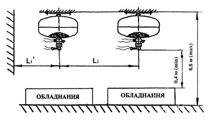
6.1.4. Modules must be placed on the ceiling or wall of protected premise using personal or special brackets. During mounting fire-extinguishing systems on the basis of SPRUT modules, next main requirements must be satisfied (fig. 6):
-distance between LSTD of adjacent modules Li must satisfy the requirement: Li Sm.pr 0,5;
- distance from module LSTD to the wall Li ‘ must satisfy the requirement: Li ‘ 0,5 Sm.pr 0,5;
- if height of the premise is higher than indicated in table 1, it is allowed to place modules in tiers, at that the vertical distance between brackets of modules in the upper and bottom tier mustn’t be higher than values, indicated in table 1.
- cables of starting and signaling circles of modules must be protected from harmful influence of the environment, including during fire.
6.1.5 Fire-extinguishing devices of control and lines of electric start must be chosen on the basis of design solutions and necessity of simultaneous start of modules, which are included in automatic fire-extinguishing system, taking into consideration parameters of electric starting signal of each module (voltage on the contacts of electromechanical actuator is not less than 2V, current
not less than 200 mA, impulse duration - up to 0,1s).
6.2 Directions about modules mounting ATTENTION!
Before the beginning of mounting it is necessary to be certain that block-screw is in place (pos. 10, fig. 1, or pos. 23, fig. 4)
6.2.1 Before the start of mounting, after unpacking the module, it is necessary to control existence of working pressure in its vessel by values of indicator, which is installed in locking spray-type device.
- 14 -
Fig. 6. Modules placement at the protected object
–
Disconnect the bracket (fig. 1, pos. 12) and fix it on the ceiling or special construction in accordance with designed scheme (project) of modules placement inside the protected area.
6.2.2. Modules mounting must be done in next order:
6.2.2.1. For modules SPRUT-1*, SPRUT-3, SPRUT-6, SPRUT-9, SPRUT-12, SPRUT15:
Place module on the bracket, after what fasten it using check-nut from the possibility of rotation. On the sprayer, inside threaded hole M8 place the electromechanical actuator up to stop. Connect (solder) electric cables from fire-extinguishing device to pressure signal device and to electromechanical actuator
6.2.2.2. For modules SPRUT-1-01*, SPRUT-3-01, SPRUT-6-01, SPRUT-9-01, SPRUT12-01, SPRUT-15-01:
Place module on the bracket, fasten in using check-nut from the possibility of rotation. Connect (solder) electric cables from fire-extinguishing device to pressure signal device.
6.2.2.3. For modules SPRUT-1-02*, SPRUT-3-02, SPRUT-6-02, SPRUT-9-02, SPRUT12-02, SPRUT-15-02:
Place module on the bracket, fasten in using check-nut from the possibility of rotation. Note.* Fasten modules SPRUT-1 (1-01), (1-02), using collar.
6.2.3 It is necessary to be careful during mounting, not allowing mechanical damages of locking spray-type device.
ATTENTION!
After mounting the module before putting it on duty it is OBLIGATORY to delete block-screw (pos. 10, fig. 1, or pos. 23, fig. 4)
6.2.4 After mounting all modules on the protected object, put on electric circles of pressure signaling devices and stimulus in maintenance standby mode.
6.3 After module triggered it is necessary to make following actions:
- disconnect electric cables of signaling and starting circles of module;
- dismantle module from the bracket’;
- twist locking spray-type device from the opening of the module vessel;
- clean locking spray-type device from remainders of fire-extinguishing powder, check and if it necessary change rubber rings, lubricate connecting details by thin layer of ЦИАТИМ 201 lubricant, and assemble the module in reverse sequence with new heat-sensitive retort;
- check locking spray-type device for pressure integrity and mount block-screw (pos. 10 fig. 1 or pos. 23, fig. 4);
- release the module vessel from remainders of fire-extinguishing powder;
- if high temperature of the fire had an influence on the module that lead to inflation and burning-out of paint on the module vessel, the last one must be hydraulically tested for durability and denseness of welded joints and base metal by pressure (2,00 0,05) MPa [(20,0 0,5) кgs sm -2)] after what refresh protecting coating;
- twist locking spray-type device in the module opening, preliminarily lubricate treaded joint by ЦИАТИМ 201 lubricant;
- charge the vessel with working gas accordingly to 13 table 1 and 2.1.9 of these exploitation directions, after what control its pressure integrity by full submergence method;
- 15 –
ATTENTION!
Carry-out charging only with block-screw (pos. 10, fig. 1, or pos. 23, fig. 4)
- mount module on the protected object accordingly to project-technical solutions; ATTENTION!
After mounting and examination of module electric circle delete the block-screw (pos. 10, fig. 1, or pos. 23, fig. 4)
6.4. Information about carried-out service and charging the module must be filled in the tables in accordance with forms, indicated in annex A.
7. TECHNICAL SERVICES
7.1. General requirements
During exploitation of modules it is necessary to carry out following types of technical service (TS);
- by the quarter;
- technical service on the grounds of warranty expiration date of fire-extinguishing powder;
- technical examination once in ten years;
7.2. Order of modules technical service
7.2.1. TS by the quarter
Once in three months:
- carry out external examination of modules to check the absence of dirt and mechanical damages and seals integrity on locking spray-type device, and also check the pressure inside the vessel (arrow of the indicator must be in green zone);
- check the resistance of module’s electric start circle (control by tester or directly by fire alarm control unit, which forms electric starting signal). Measured value must be accordingly to p.10 in table 1.
Results of TS fill in the journal of technical service registration table A1 annex A.
If during warranty period of exploitation (24 months) the pressure in the module’s vessel decreased lower than permissible level (arrow of the indicator exceeded the left bound of green zone), the module must be changed. In the case of pressure dropping in the module’s vessel lower than permissible level after the end of warranty period, the module must be dismantled and additionally charged by working gas accordingly to p. 13, 14 in table 1.
7.2.2 Technical service on the grounds of the warranty period expiration date of fireextinguishing powder must be carried out in following order:
- install block-screw and dismantle the module;
- on the factory, that carries out TS, twist out pressure indicator and expel working gas through check valve from the module’s vessel;
- unscrew LSTD from the module’s opening;
- check values of DPEC features for the accordance with TS requirements by indices “mass part of humidity” and “granulometric composition”.
Results of check-up fill in the table A1 of annex A.
If the discrepancy of DPEC quality indices to TS requirements occurred as a result of check-up, the module must be recharged. Results of the recharge fill in the table A2 of annex A.
- 16 -
7.2.3. Technical examination
In ten years after manufacturing date the technical examination is carried out in accordance with “Rules of construction and safe exploitation of vessels that work under pressure” in following order:
- install block-screw and dismantle the module;
- twist pressure indicator on the enterprise that carries out TS, and expel working gas through check valve from the module’s vessel;
- twist LSTD from the module’s opening;
- release the module’s vessel from extinguishing powder;
- carry out external and internal examination of the module;
- carry out hydraulic testing of the vessel with testing pressure of 20 kgs/cm2 . Results of the examination fill in the table A3 of Annex A
7.3. Safety precautions
7.3.1. During the exploitation of modules one need to follow “Rules of construction and safe exploitation of vessel that work under pressure” (НПАОП 0.00-1.07-94) and these exploitation directions.
7.3.2. Only persons in accordance with НПАОП 0.00-1.07-94 are permitted for exploitation and service modules.
7.3.3. Modules must be kept and placed in places that exclude possibility of mechanical damages and on the distance not less than 1 m from heating devices.
7.3.4. Only charged and sealed modules with date (month and year) of charging and technical service on the label are allowed for putting into exploitation.
7.3.5. It is necessary to safely fasten modules during charging with compressed gas to avoid traumas of maintenance staff.
7.3.6. All works with fire-extinguishing powder must be carried out accordingly to safety requirements, which are written in technical specifications of these powders.
When recharging modules with fire-extinguishing powder, the personnel, which maintain them, must be supplied with special clothes, protection facilities for respiratory apparatus and eyes.
When working with DPEC it is necessary to adhere to rules of personal hygiene. Note – recharging modules with fire-extinguishing powder and compressed gas, examination module’s vessel, is allowed to carry out only organizations that have license for carrying out these works.
7.3.7. Absolutely forbidden to:
7.3.7.1. Unseal, disassemble locking spray-type device (except of works, connected with technical service of module).
7.3.7.2. Exploit module with offending subsystems.
7.3.7.3. Exploit module after the end of module examination period.
7.3.7.4. Use keys with elongated holders.
7.3.7.5. When disassembling plug connections of locking spray-type device of the module it is necessary to make sure that there are no pressure of compressed gas in the module’s vessel.
It is forbidden to repair and compact joints when there is pressure of compressed gas in the module’s vessel.
7.3.8. When using modules for object protection, at which there are people, it is necessary to carry out special training of the object’s personnel in the case of fire.
7.3.9. It is necessary to provide its safe fastening when installing module.
- 17 –
8. CONNECTION SCHEMES OF SPRUT MODULES’ ELECTRIC CIRCLES
In construction of SPRUT modules, designed for creation of automatic fire-extinguishing systems, two electric devices are used:
- pressure signaling device (PSD), which is microswitcher, closed if there is working pressure in the module’s vessel and it is unclosing if the pressure drops;
- electromechanical actuator (EMA), designed for forced destruction of heat-sensitive retort, which is holding element of LSTD valve of module.
8.1 Pressure signaling device
Maximal current, which commutates by pressure signaling device – Imax = 0,5 А.
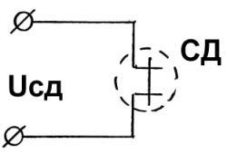
Voltage in pressure signaling device circle – Upsd = 12 V.
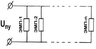
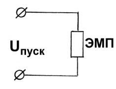
8.2 Electromechanical actuator (EMA)
Parameters of starting signal EMA:
- voltage on clamps of EMA – Ustart 2 V;
- starting current – Istart = 0,2…0,5 А
Internal resistance of electromechanical actuator is
REMA = 2…6 Оm.
Current value, which guaranteed will not lead to module triggering (let-go current) during checkup of starting electric circles integrity is Isafe 0,01 А.
8.3 Connection of several modules
In the case of automatic fire-extinguishing systems creation on the basis of several SPRUT modules it is necessary to provide their simultaneous triggering. For this EMA must be connected in a parallel way to the source of starting signal Ustart of control unit. It is possible to use control devices that form starting signal with voltage 12 або 24 V and provide parameters of EMA starting voltage, mentioned above. Duration of starting impulse Тstart 0,1 с.
- 18 –
Table
ANNEX A
№ Type of technical service
Date
Remarks about technical condition
Position, surname and signature of person, who is responsible for carrying out the technical service
Table A2. Registration of module charging with fire-extinguishing powder
№ Marking and number of technical specifications of fireextinguishing powder
Lot number and manufacturing date of fire-extinguishing powder
Charging date (recharging) Signature of person, who carried out module charging
Table A3. Technical service registration of the module’s vessel that works under pressure
№ Number of module’s vessel Checkup date
Date of next checkup Signature of person, who carried out the examination
Contact information
Developer, supplier: Limited Liability Company «Research-and-production company «Factor»
Address: 03038, Kyiv, 32 Fedorova street
Phone (044)338-50-27; (044)338-50-16; cell (044)223-90-65
E-mail: engineering department – sprutmpp@gmail com
Website: www.factor-kiev.com
- 19 -
A1. Technical service registration
