Stella Pavlidou
COMPUTATIONAL DESIGNER ARCHITECT - ENGINNER
MSc Building Technologist
Computational Designer
Dipl. Architect Engineer
I am an experienced Architect - Engineer with 4 years of in-depth work in the architecture & planning industry. High skilled in computational and parametric design, geometry configuration and multi-objective optimization. I am passionate about creative and innovative thinking towards sustainable and effective solutions. My recent research focuses on Artificial Intelligence workflows for structural optimization.
SKILLS
Parametric Design
Multi-Objective Optimization
Scripting
Deep Learning
Sustainable Design
Architectural Design
Technical Drawing
SOFTWARE
Autodesk Autocad Rhinoceros
Grasshopper [ Kangaroo
Karamba3D
Ladybug Tools
Honeybee Octopus]
Revit
Adobe Suite
V-ray
SketchUp
Python
LANGUAGES
English: TOEFL, Certificate of Proficiency in English, University of Cambridge (2015)
French: Diplôme d’études en Langue Française (DELF), 1er degré (2005)
Greek: Native Speaker
S TELLA P AVLIDOU
EXPERIENCE
2021- 2022 (4 months)
Student Assistant , TU Delft University

Creating Tutorial Content for FEM software: TOI-Pedia Karamba3D
2016-2020 (4 years)
Architect- Engineer, ASPA KST Architecture Design Planning
Participation: Design Development, Planning permission, Construction Documentation, 3d visualization.
2015-2016 (6 months)
Architectural Intern, ECDM Architectes
Participation: Facade Studies, space planning.
2013-2014 (8 months)
Architectural Intern, Mimnermou 2 Architects

Participation: Nisiros Lecture and Research Center Applied Research Program
2013-2014 (2 years)
Computational Lab Assistant, School of Architecture, University of Patras
EDUCATION
2022
TU Delft University, MSc Architecture, Urbanism and Building Sciences
MasterTrack: Building Technology
Τhesis: Deep Generative Design
Grade: 8.5/10
Grade: 7,9
2016
University of Patras, School of Architecture
Architecture -Engineering Diploma
GPA: 8.56/10
Τhesis: Restoring the Path
Grade: 10/10
AWARDS
2021
MEGA 2021 Student Contest, Most Integraded Design
TU Delft University, Techniplan Adviseurs
Role: Computational Designer
2014
Best student performance during the third year of studies, State Scholarship Foundation of Greece (IKY),

2014
Shortlist_D3 housing of Tomorrow
Project “City overlap”
Team: M. Ch.Akrivou, Ph. Dimoglou, I.Theodosopoulou,S.Pavlidou
ARCHITECTURE PORTFOLIO
COCOMAT HOTEL Professional-Project, ASPA KST Team Project
3.
...Kip Calm and go to the Expo Competition Entry Team project
4.
Restoring the Path Academic Project Individual Project DESIGN INFORMATICS 1. Deep Generative Design Academic Project Individual Project
.Khufu Boat Museum Academic Project Individual Project
5.
2.
Deep Generative Design
A Deep Learning Framework To Optimize Shell Structures
Type: Academic Project
Role: First Author
Mentors: Dr. Charalampos Andriotios, Dr. Michela Turrin
Year: 2022
Software: Rhino3D,Karamba 3D
Programming Languages: Python (NumPy,NetworkX, Keras, Tensorflow, COMPAS)
“This section presents a summary of my Graduation Thesis for MSc Architecture and Urbanism, Building Technology at TU Delft University. The Thesis suggests an Artificial Intelligence based Framework to optimize the topology of shell structures.
The trainning dataset was created with Python libraries (NumPy, COMPAS, NetworkX etc), Machine Learning Models were built with Python Tensorflow and Keras, FEM simulation was operated with Karamba3D.” Full report can be found here Deep Generative Design.”
01
Problem Statement and Design Assignment
The topology of shell structures is critical and affects cost, assembly time, structural performance, and aesthetics. Designers and engineers need conceptual and practical tools to explore it. There are many variants that describe a design and exploring the design space for optimum solutions is a time-consuming process. Generative Models that integrate Artificial Intelligence can minimize the number of variants in a smaller sized space and could potentially be integrated in an optimization workflow.
Main Question
According to the problem statement, mentioned above, the main research question is if an AI based framework can generate new structurally effective solutions, in relation to the dataset that was used for training. This would prove that AI can be a powerful creative assistant for designers and engineers, and could potentially help expand the possibilities of generative design.
Context
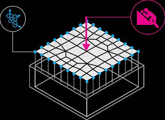
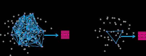
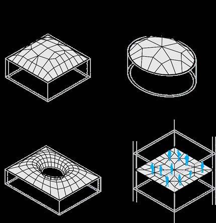
The framework of this thesis focuses around the case of a shell structure with a quad based topology. Thex optimization process for this thesis aims to minimize the deflection, the utilization and the mass of the structure to prove that AI can help to optimize shell structures. In the future more criteria can fit in this framework . The example below demonstrates an optimized shell structure in the case of a flat roof. A point load of 1 kN is taken into account at the middle, for repair access.
RESEARCH PROBLEM
RESEARCH WORKFLOW
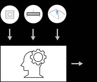
The proposed steps are:
Create a dataset with various patterns and measure their structural performance (performance indicators will be displacement, utilization and the structure’s mass), using Finite Element Method software (FEM).
Train a Variational Autoencoder with the produced data.
Decoded Data is used to train a surrogate model that is able to predict a design’s structural performance.
Use a Gradient Based Optimizer that propagates back to the encoded data to search for best solutions.
Produced results are assessed to see if more effective solutions are generated.
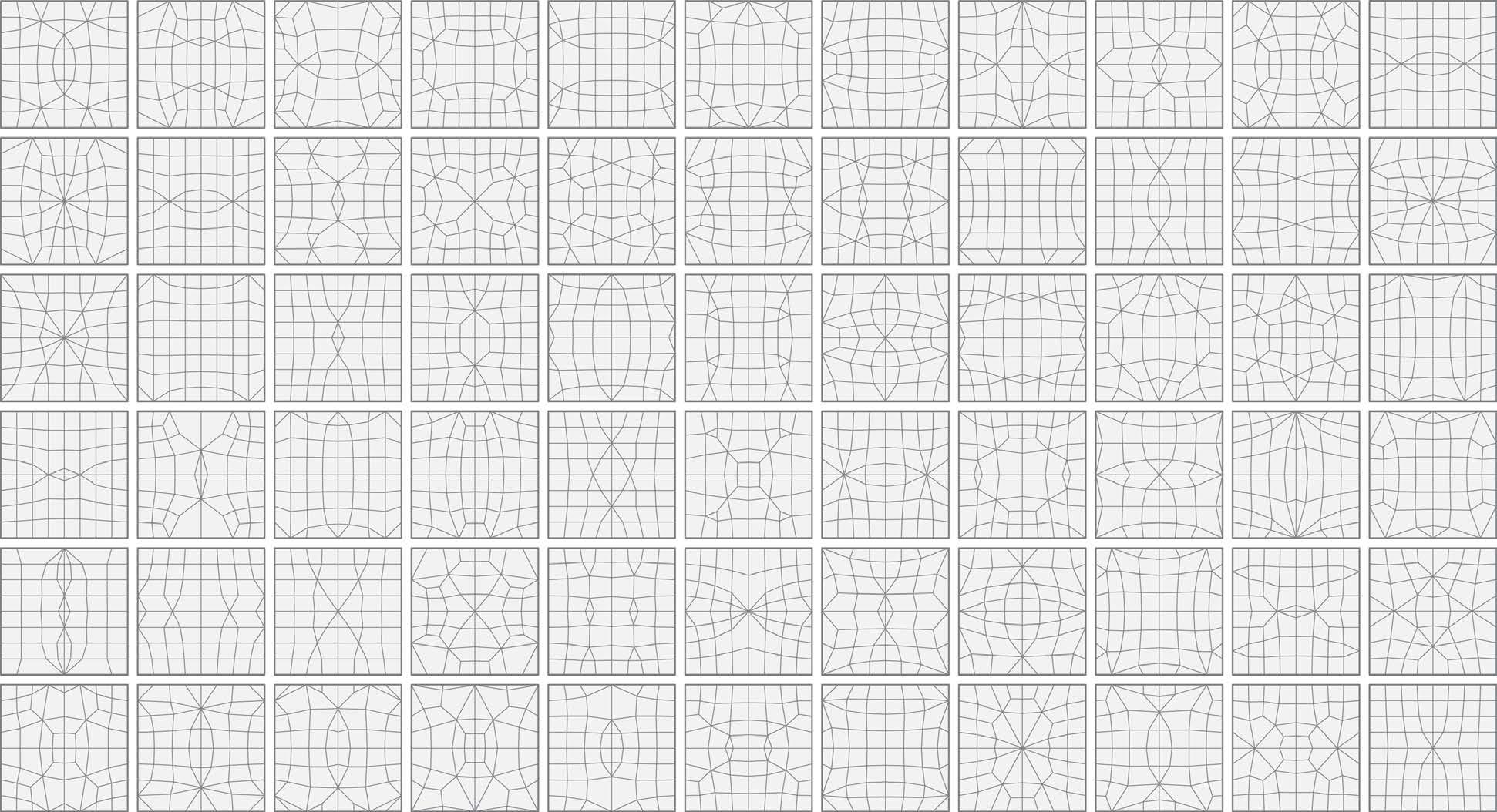
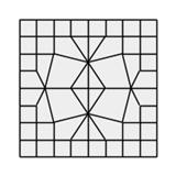
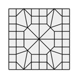
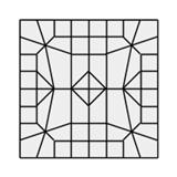
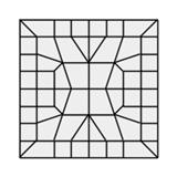
CREATING THE PATTERNS
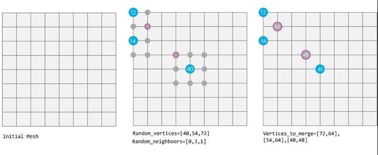
The dataset is created using python and the COMPAS framework. To create the dataset for this thesis another method will be followed that can result in the same patterns by merging points:
• First a set of points is chosen.
• Then they are either merged to their centre point or if one of them is an extreme point they are merged at this one.
Step 1
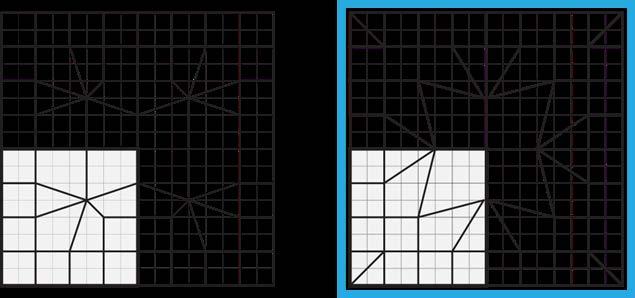
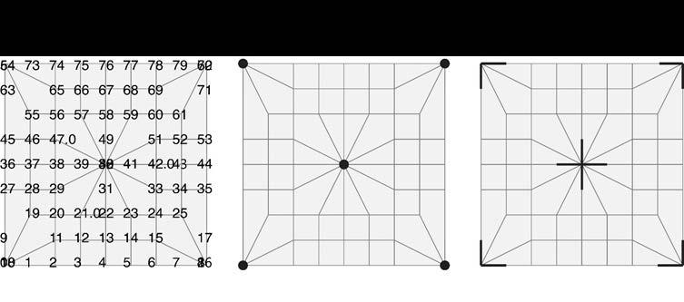
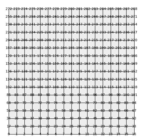
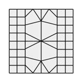
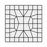
First an initial mesh is specified. Then, random vertices are selected. Another vertices is chosen from the lists of their neighbours, by choosing random seen at the image in the middle. These random vertices and their selected form sub-lists are all placed at a list with the vertices_to_merge, as image on the right.
Method explanation
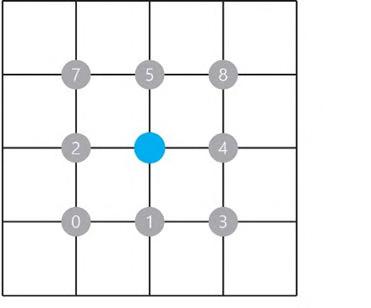
Every vertex v of the mesh has a set of neighbouring vertices that are connected to v by an edge. We can chose a neighbour for each vertex by selecting the index from the list of its neighbours. Various mesh tessellations can occur when merging random vertices with random neighbours.
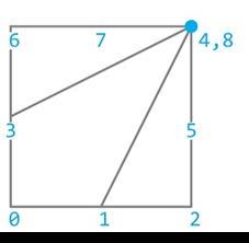
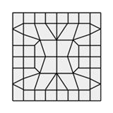
Step 4
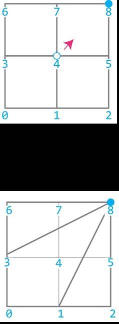
The merged vertices are going to replace the initial vertices. A simpler to explain the method. In the image below the goal is to merge the vertex vertex 8(v8). As the vertex 8 is an extreme point, then it is the merged vertex In the list of vertices the v8 replaces the v4. After this step a new topology
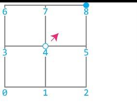
However double and unused vertices occur (vertices 4 and 8 )as well faces (face 3). Therefore, removing unnecessary vertices and faces is
A vertex with its neighboors
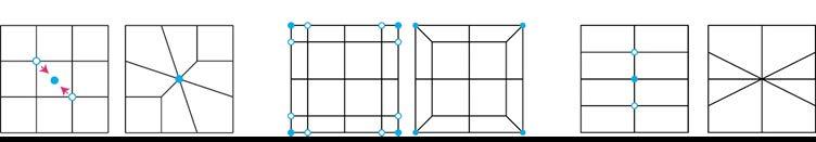
Another set of random indexes as selected neighbours as seen at the
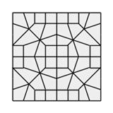
Step 2
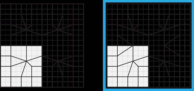
In this step the symmetrical vertices of the vertices_ to_merge are added in a new list. If a vertex exists in more than one sub-list then these sub-lists are merged.
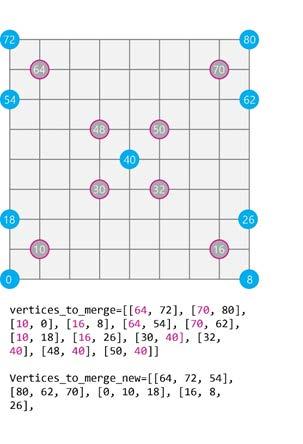
Step 3
A new list with the merged vertices is created that includes the coordinates of the points where the vertices_to_merge are going to be joined. These points are usually the mean point or centre point of the vertices. If some vertices on the sub-lists are extreme vertices, then it is their centre that is needed for the new list. If one vertex of the sub-lists is a corner point, then this point is the one that is placed on the merged_vertices list.

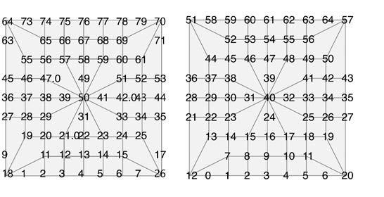

mesh is used vertex 4(v4) with vertex as well. topology is created.
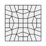
Step 5
Compas can create meshes from either lists or dictionaries as inputs. After clearing the unnecessary the vertices and faces, Compas creates new meshes that are dictionaries whose key numberst are not in order. This would be ok, however the relaxation algorithm didn’t seem to work in this way so the order needed to be fixed.
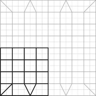
Step 6
Finally the mesh is relaxed. The boundary points are the anchor points and the force density algorithm is used with a load of 2kN/m3 prescribed in the edges
as zero-area needed.
DATASET PRE-PROCESSING FOR TRAINNING AI MODELS
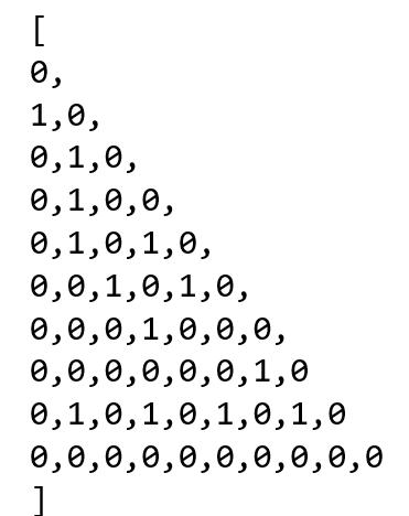
In order to train the model, tensors that will occur from arrays with the same shape need to be used. As the generated meshes have different number of vertices and faces, their final lists cannot be used as they are in the dataset. All the training data are exported after generating the new meshes and before relaxation.Meshes can be described as graph data using adjacency matrices. As various new points are creating after merging random initial points, a denser mesh, that is occurring after subdividing the initial one by two, is used.
Multiple graphs are created but they all share vertices with the same coordinates. This means that the training data describe an unrelaxed mesh.
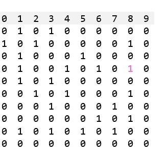
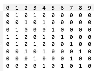
A starting mesh with its adjacency matrix. A final mesh with its adjacency matrix.
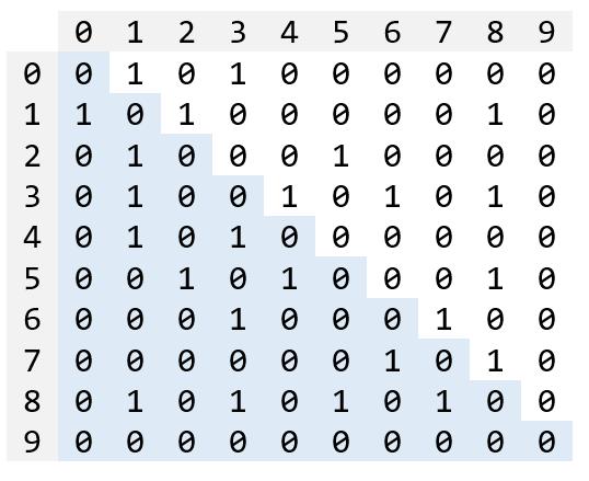
The adjacency matrix that describes the connections of nodes is always symmetrical to its diagonal axis. As described in Chapter 4 the tensors are flattened before passing inside fully connected layers. The size of the training sample can be minimized by removing the double sequences that occur during the dataset pre-processing step. The highlighted part of the adjacency matrix (that describes a simpler mesh) bellow represents the flattened information that is kept.
Using a quarter of each of the adjacency matrices
A final attempt was done to test the performance of the network by minimizing the input information. Since the meshes are symmetrical we can keep one quarter of the adjacency matrices. The original adjacency matrix has a shape of [289,289]. Keeping one quarter of the information means the new matrix has a shape of [81,81]. Therefore we need to keep in both axis the indices included in the shape bellow.
DATASET GENERATION
The following process describes the generation of two databases: one for creating the data appropriate for training the generative model and another for creating mesh data that will be simulated with FEM software to create the labels that the surrogate models will learn to predict.
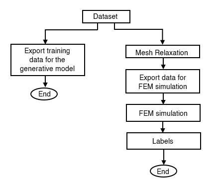
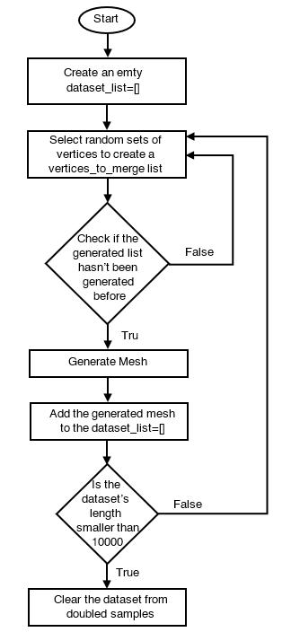
These are the following steps:
First an empty dataset_list is created
Then random sets of vertices are selected so a list with “vertices_to_merge” is created. The combination of the vertices and the length of the list is also random. Since the symmetrical vertices are going to be added, the random choice is limited to one quarter of the mesh.
If the generation of the “vertices_to_merge” hasn’t been generated before, the algorithm moves to the next step. If not another random set is generated.
A new mesh is created according to the list of “vertices_to_merge” and it is added to the dataset_list
If the desired dataset_list length is reached (10000 in this thesis) the algorithm is moved to the next step, if not the second step is repeated.

The dataset_list is cleared from doubled samples.
The dataset_list is converted to data appropriate for training a machine learning model. For this thesis 5890 training samples were generated.
The new meshes are relaxed and data appropriate for FEM simulation are exported.
The FEM simulation creates the labels that will be used in the surrogate model.
PERFORMANCE INDICATOR
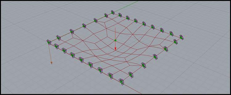
All the data including mesh information are exported in text documents. Then they are imported inside the Grasshopper environment in Rhinoceros. For FEM testing Karamba3D is used.
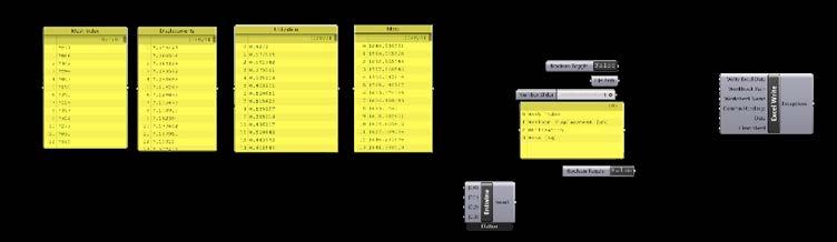
The mesh’s edges are tested as steel beams network( Steel S235) with a IPE80 cross section.
A point load of 1 kN applied at the centre of the network. All the boundary points are used as fixed supports.
After testing the following performance indicators are extracted and stored in a csv file:
The Maximum Displacement in cm.
The Maximum Utilization (ratio between the tensile or compressive strength and the maximum allowable stress)
The Mass of the structure in kg.
All performance indicators are normalized to fit in the range between 0 and 1. Then a performance value is assigned to each index using the following formula:
Performance = 0.4 ×Normalized Displacement+0,4×Normalized Utilization +0,2×Normalized Mass
The 10 best performed mesh tessellations are excluded from the training dataset (the highlited ones) to see if Artificial Intelligence can solutions better than them.
FEM
|
SIMULATION
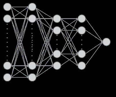
THE VARIATIONAL AUTOENCODER
Architecture
The Variational Autoencoder is based on F. Chollet’s VAE model (Chollet, 2020) with changes on hyperparameters ( layers, the batch size, epochs and learning rate). Keras and Tensorflow python libraries were used for implementing the VAE.
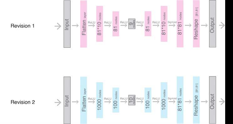
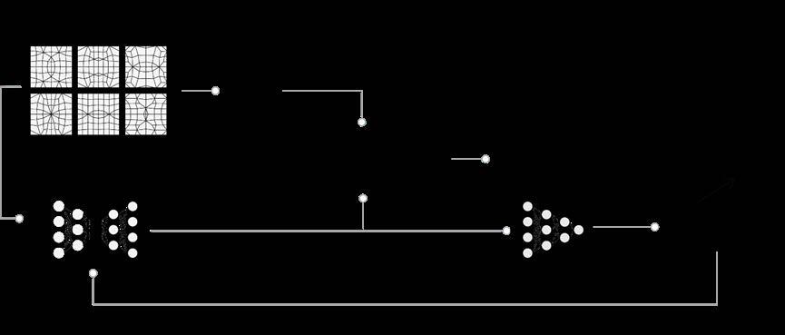
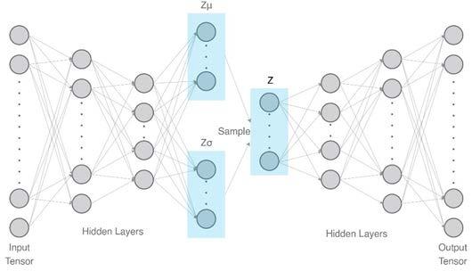
The VAE is a deep learning model that consists of an encoder and a decoder with hidden fully connected layers (dense layers). The input data pass through an encoder that is able to shrink the data to fit in a latent space. A final layer called sampling layer in the encoder is able to perform a reparameterization trick to make sure that the latent space is regular. The decoder then attempts to reconstruct the input data. The model is trained by dividing the dataset in batches. After passing the entire dataset through the neural network one epoch is completed. The neural network measures the error of reconstruction and updates the weights at its nodes. A workflow of the whole network is presented below.
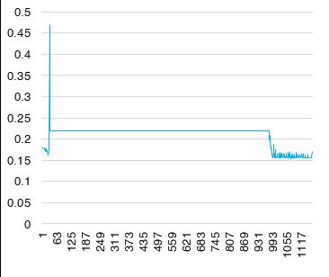
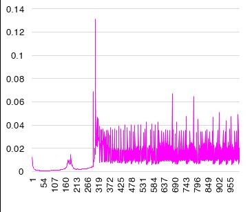
Charts demonstrating the loss function during training, depending on the architecture of the VAE are shown below.
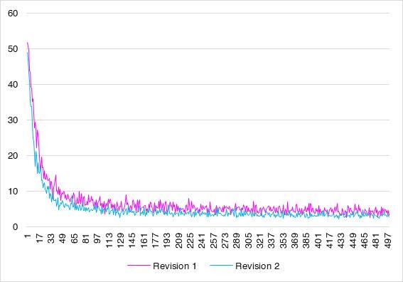
Epochs
THE SURROGATE MODEL
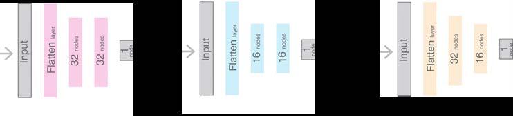
Architecture
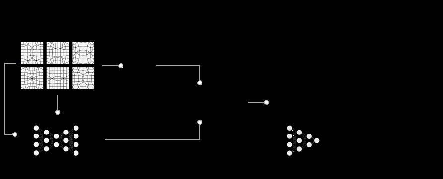
Training a surrogate model to predict the normalized performance out of the VAE’s decoded data
The Surrogate Model attempts to fit the input data x_train to the performance scores y_train. Input data are the decoded samples. 50 samples are excluded from the training process to evaluate the training. Input shape is [1,3240] and the output is a single score. The architecture tested included an input layer, a flatten layer and two dense layers.
Revision 1
Revision 2
Revision 3
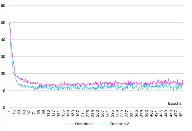
Charts demonstrating the loss function during training, depending on the architecture of the Surrogate Model are shown below.
From Left to the right: Validation Loss and Trainning Loss
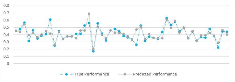
Comparison of predicted and actual performance for 50 test data that were not used when training the surrogate model
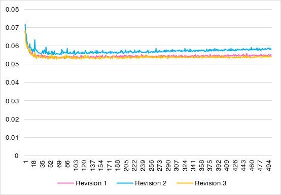
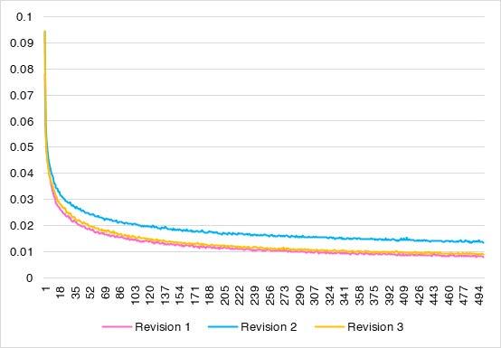
Epochs Train Loss Epochs Validation Loss
GRADIENT DESCENT OPTIMIZATION
After training the VAE and the Surrogate model we are able to retrieve the Model’s gradients. The gradient we are interested in is that of the structural ‘performance’ (y vector) with respect to the latent space (z vector). The Gradient Descent algorithm searches for the minimum y vector.
Z = Z – lr ∂y/∂z (Z0, Zn,)
lr : Learning rate that determines how large the update or moving step is.
Z: The latent’s space z vector to be updated
Y: Structural Performance
APPLICATION
The framework of this thesis focuses around the case of a shell structure with a quad based topology. The optimization process for this thesis aims to minimize the deflection, the utilization and the mass of the structure to prove that AI can help to optimize shell structures. In the future more criteria can fit in this framework .
The example below demonstrates an optimized shell structure in the case of a flat roof. A point load of 1 kN is taken into account at the middle, for repair access.
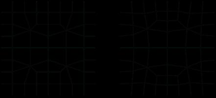
The images below correspond to the Case 2 in the Chapter 3.2 and demonstrate the initial design before and after relaxation. The starting performance score is 0.17705911.
From left to the right: The initial design before and after
RESULTS
Learning rate: 0.5
Performance score of initial design: 0.177
Starting Design
Estimated performance score of the optimized design: 0.142
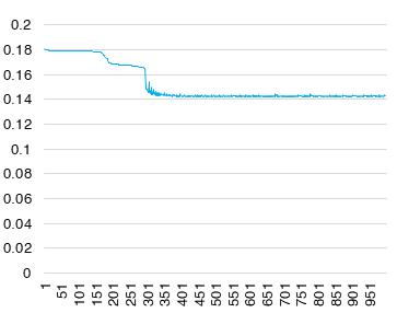
Actual performance score of the optimized design: 0.085
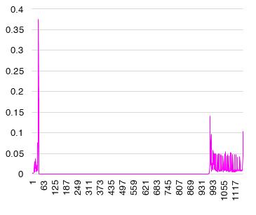
Learning rate: 2.5
Performance score of initial design: 0.177
Estimated performance score of the optimized design: 0.165
Actual performance score of the optimized design: 0.044
Novel Design: Yes
Optimized it by 206%.
Novel Design: Yes
Optimized it by 394%.
Estimated Performance Gradient RMS Iterations Iterations Estimated Performance Gradient RMS Iterations Iterations
In the future more criteria can fit in to the workflow. For instance a relaxation in the z axis, various boundaries and application other load cases.
Some scenarios of shell structures with different boundaries and load cases, where AI could be used for topology optimization are demonstrated below.
 The final design using the AI output result for a learning rate of 0.5
The final design using the AI output result for a learning rate of 2.5
The final design using the AI output result for a learning rate of 0.5
The final design using the AI output result for a learning rate of 2.5
Khufu Boat Museum
Academic -project,Technoledge Structural Design
Type: Academic Group Project
Contribution: Author of Presented Documents
Mentors: Dr. Faidra Oikonomopoulou Dr. Mauro Overend
Year: 2021
Author of Drawings: Stella Pavlidou
Software used: Grasshopper,Octopus, Karamba3D, Autocad
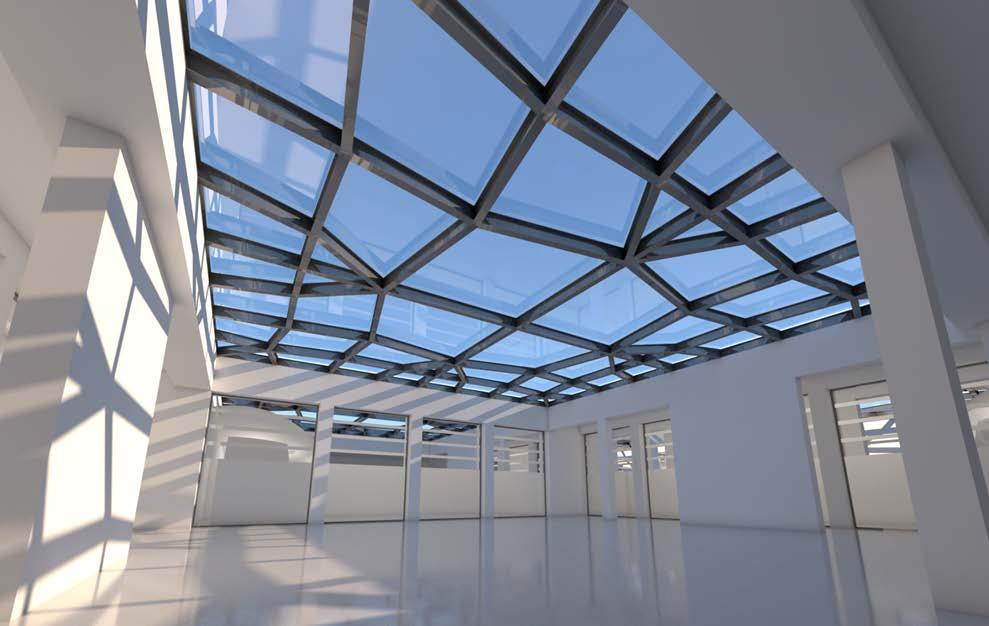
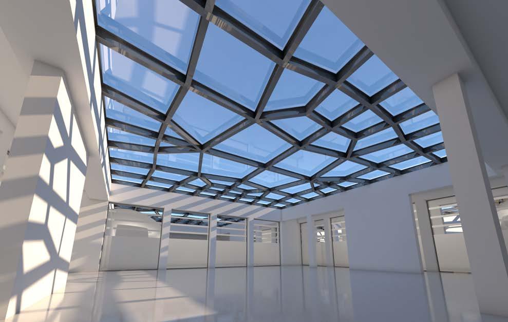
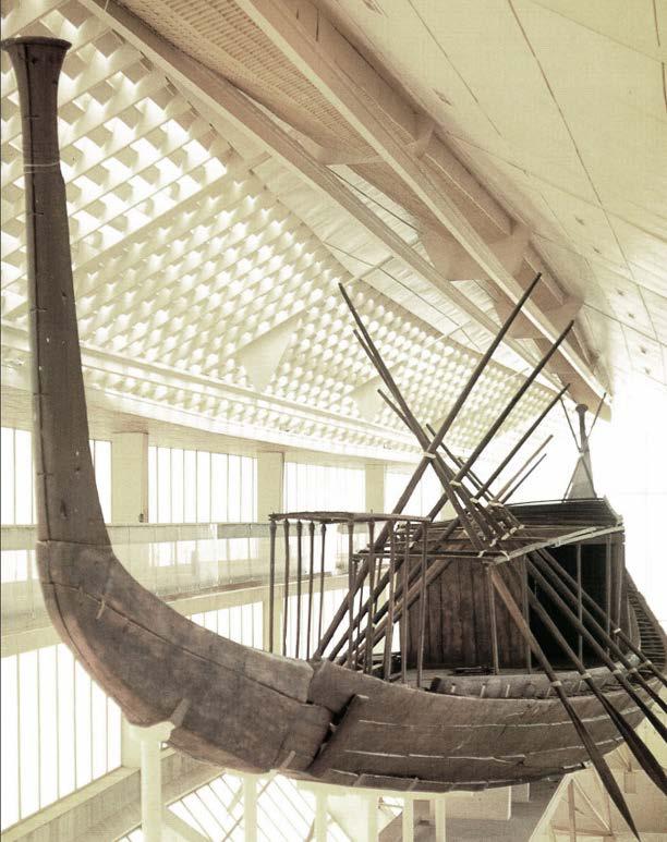
“This section presents my work for the course “Technoledge Structural Design”. The task is to design a new musem for the exhibition of the Khufu ship in Egypt made out of structural glass. Bearing elements are made out of glass, apart from the roof which is wooden. In order to minize occuring forces the roof was parametrized and optimize for structural performance”
02
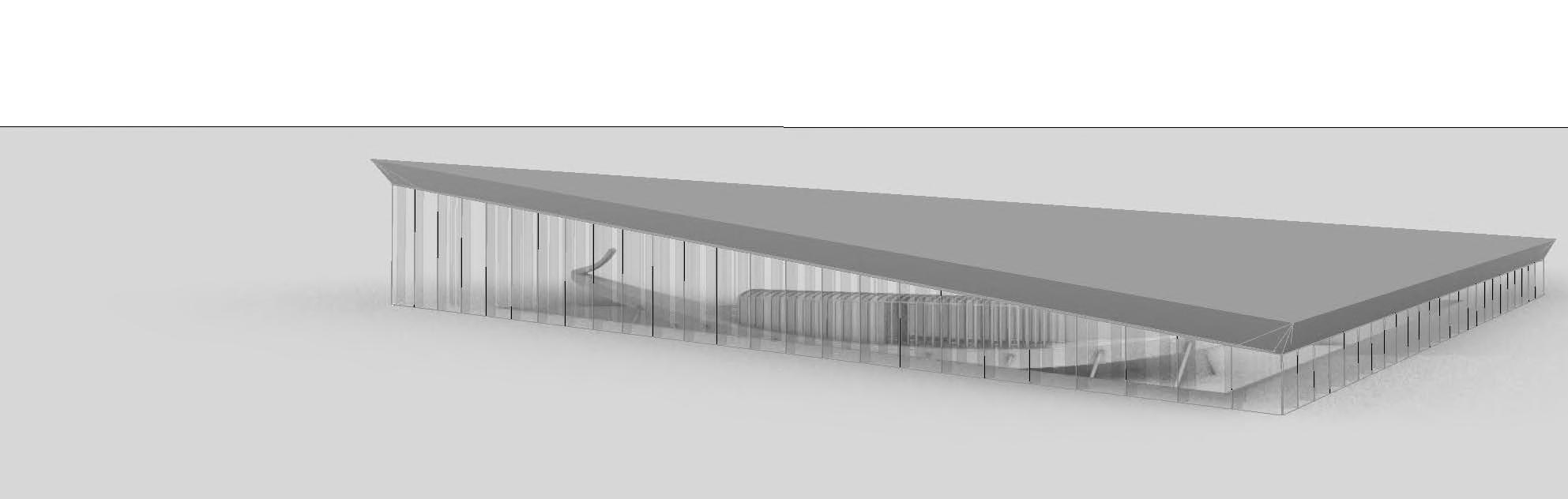
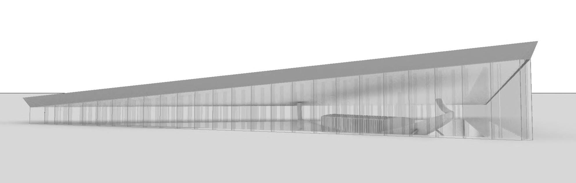
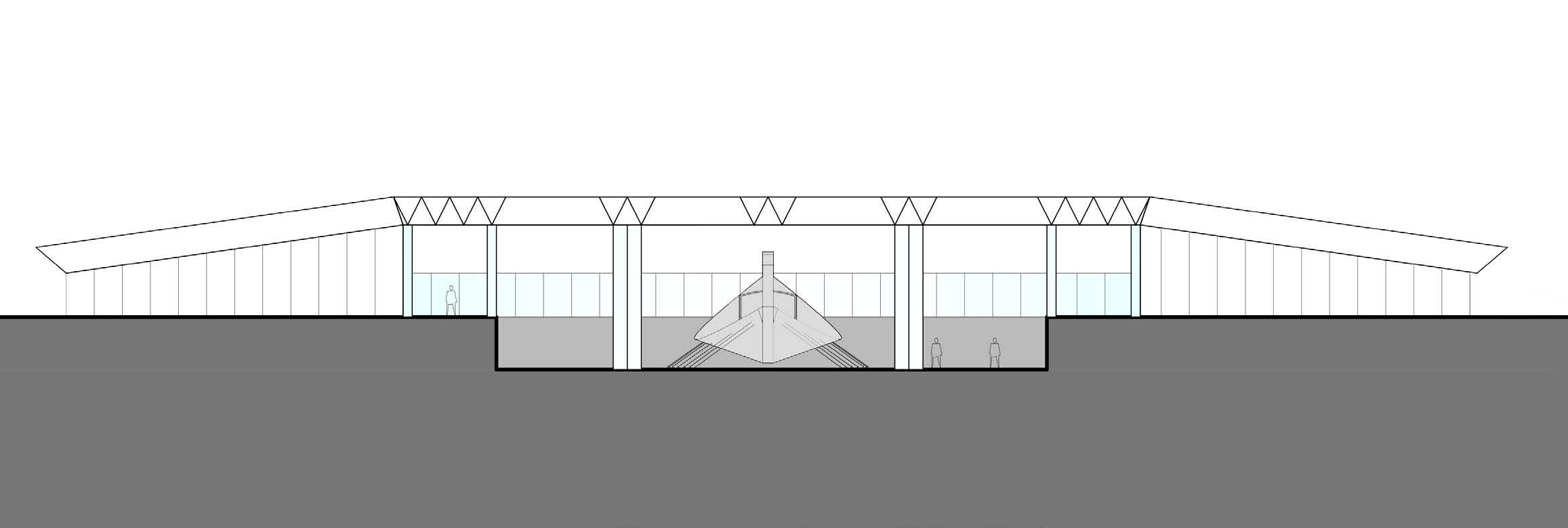
The context and the type of special exhibit demanded a very gentle handling of the design. The main goal of the architectural design was first and foremost the respect of the great monument. The concept derived from the need to create a structure that has a simple but dynamic shape and blends into the scenery of the desert allowing for views towards the great pyramids.
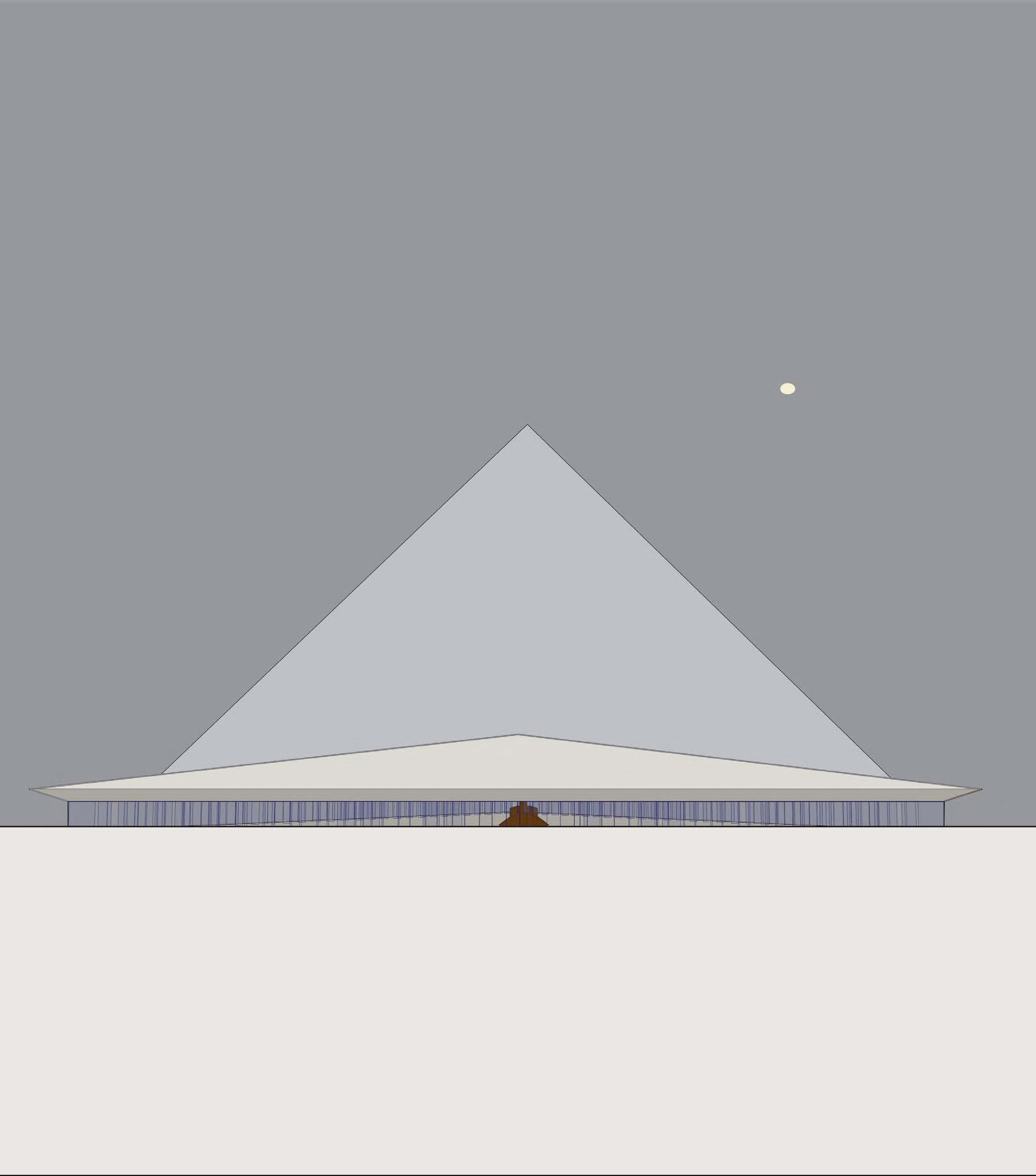
To serve the aforementioned purposes, a triangular floor plan pointing at the north was proposed as a reminder of the shape of the pyramids. Furthermore, an inclined roof towards the south and partial excavation of the ground was selected in order for the structure to apprear as if it emerged from the desert sand dunes. These measures also help the thermal performance of the building as they reduce significantly the direct solar heat gains.
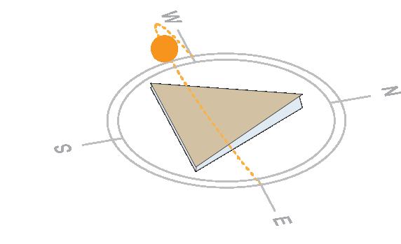
Inclined


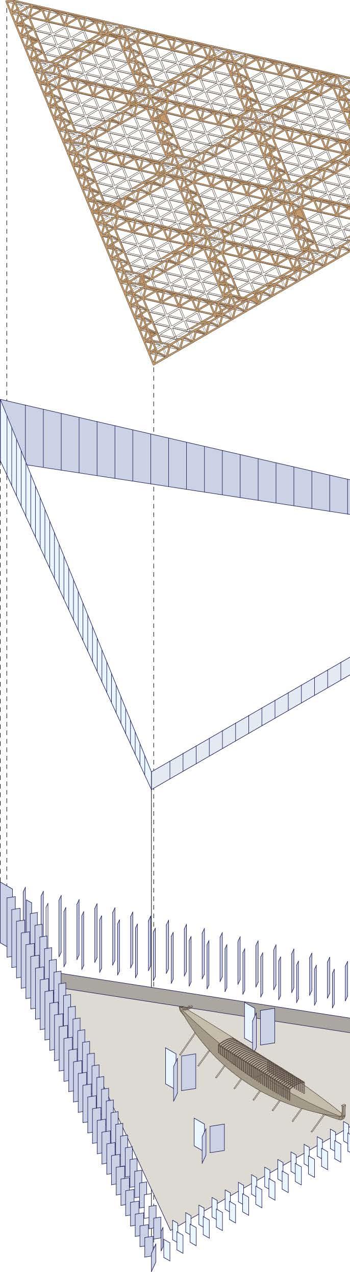
COMPONENTS AND SIZING
roof that allows more light entering in the north side and reduces the solar gains at the south side
Wooden Space Frame (3D)
Wooden Space Frame (2D)
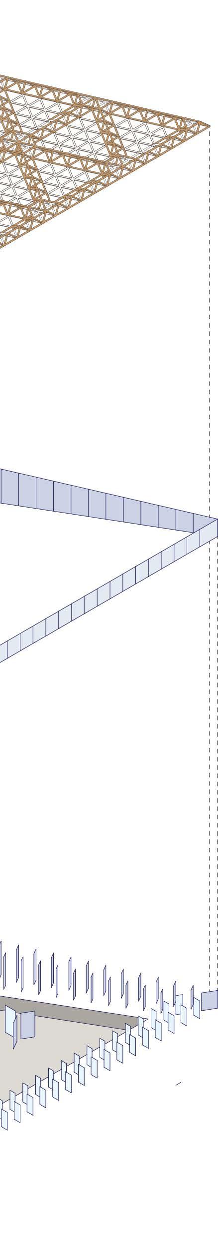
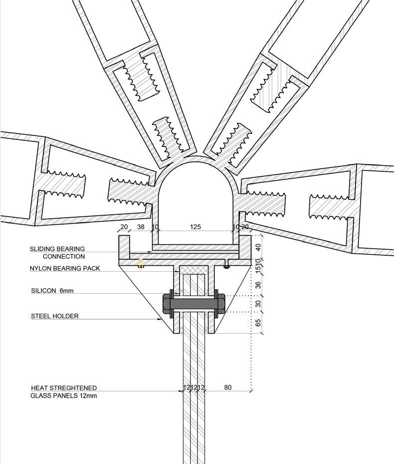
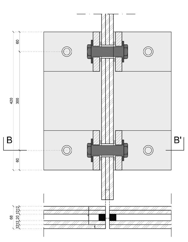
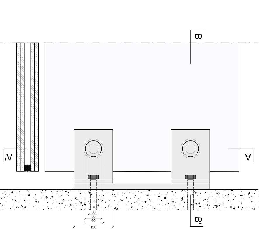
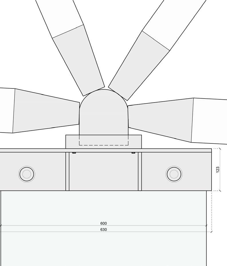
The bearing elements consist of a wooden space frame for the roof which is supported by two layes of glass fins at the boudary edges of the museum, which also form an external corridor and internal fins that surround the boat
SIZING
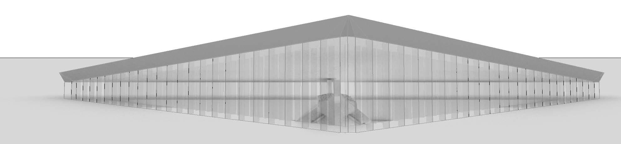
EAST VIEW
Glass Panels
Glass Fins
WESTVIEW
NORTH VIEW
ROOF’S SPACEFRAME PARAMETRIZATION
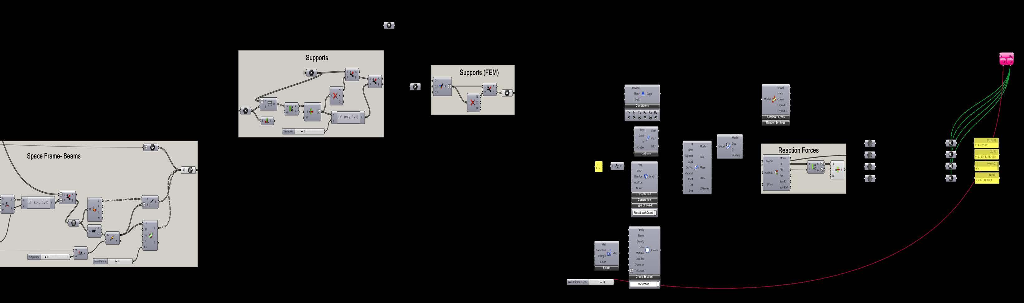
To structurally optimize the roof, its design is parametrized. The logic is demonstrated in the following steps. The definition is presentes bellow
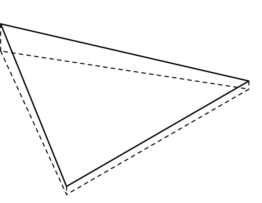
The boundary is specified and the initial boundary is rotated
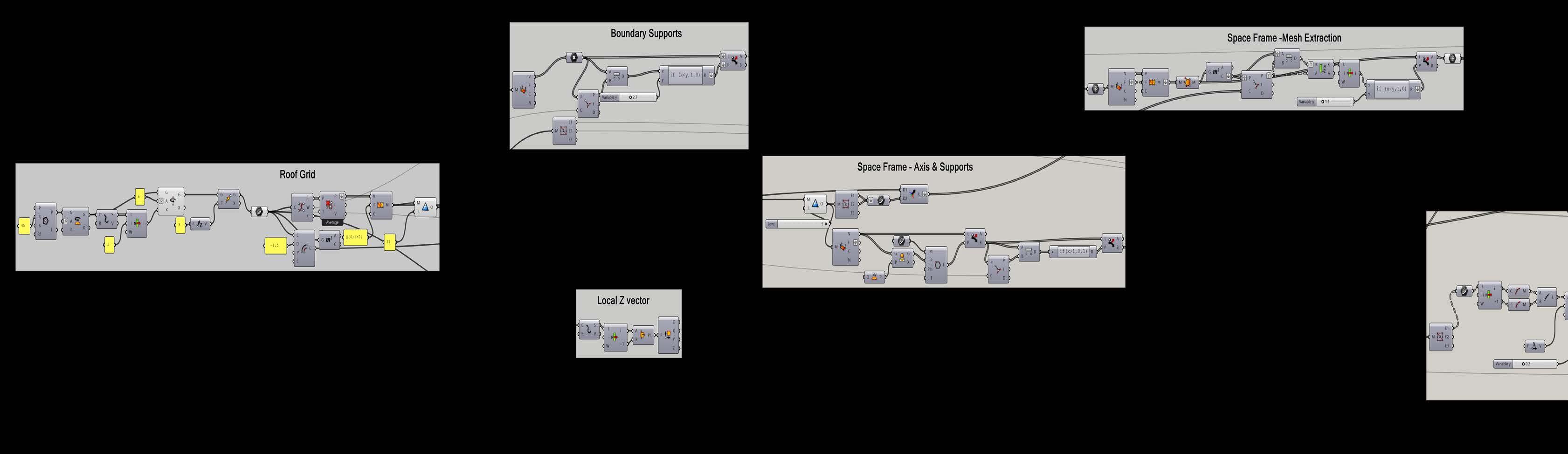
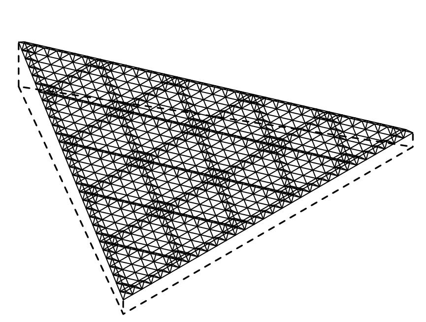
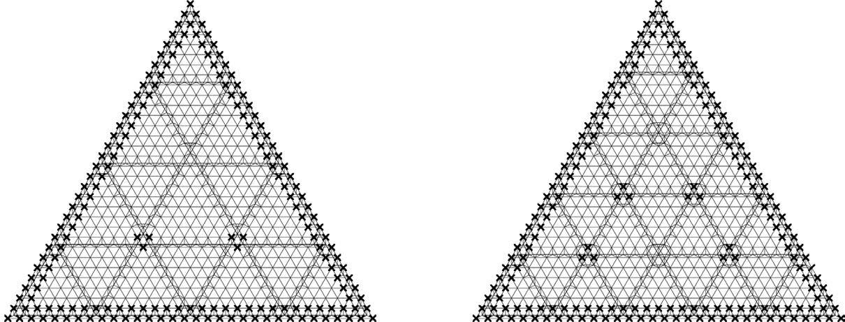
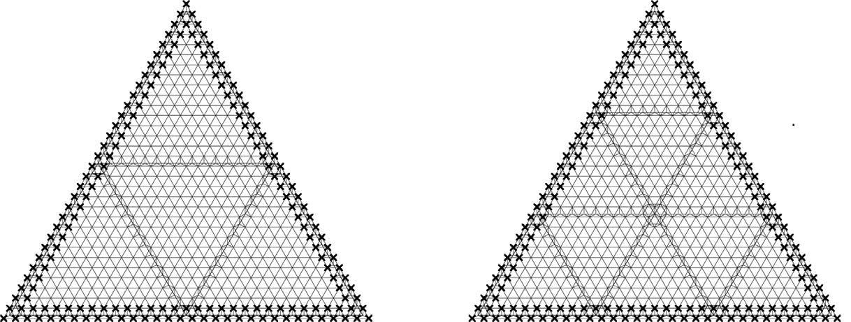
To define the axis for the 3d spaceframe the initial mesh is again subdivided using Weaverbirds Sierpinski Triangles Subdivition.
A mesh is created and subdivided, to the desired Grid, using Weaverbirds Sierpinski Triangles Subdivition.
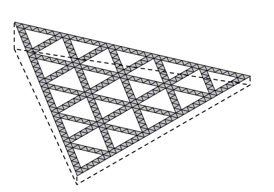

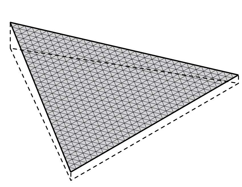
The edges of the previous step that overlap with the initial subdivition define the mesh that will be used for the 3D spaceframe
1.
1. 3.
3.
4. 4.
2.
2.
The spaceframe is created using LunchBox.
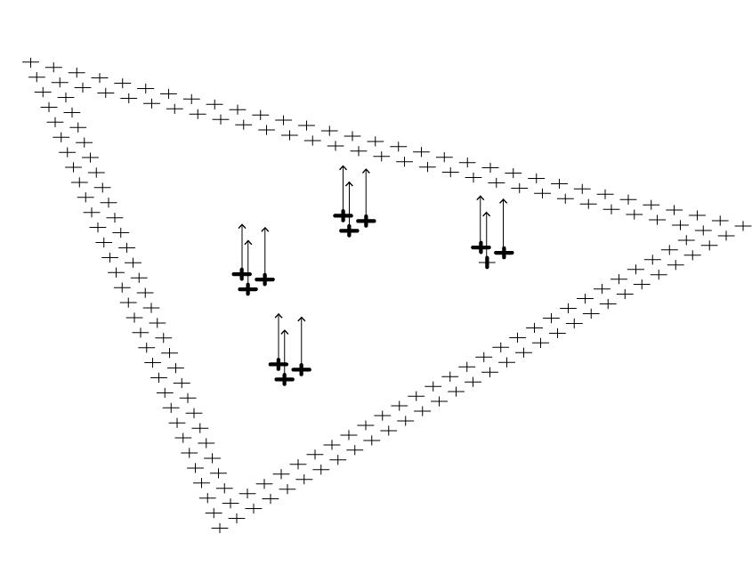
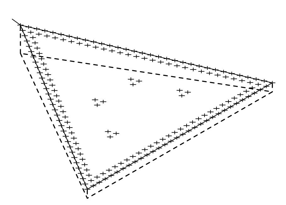
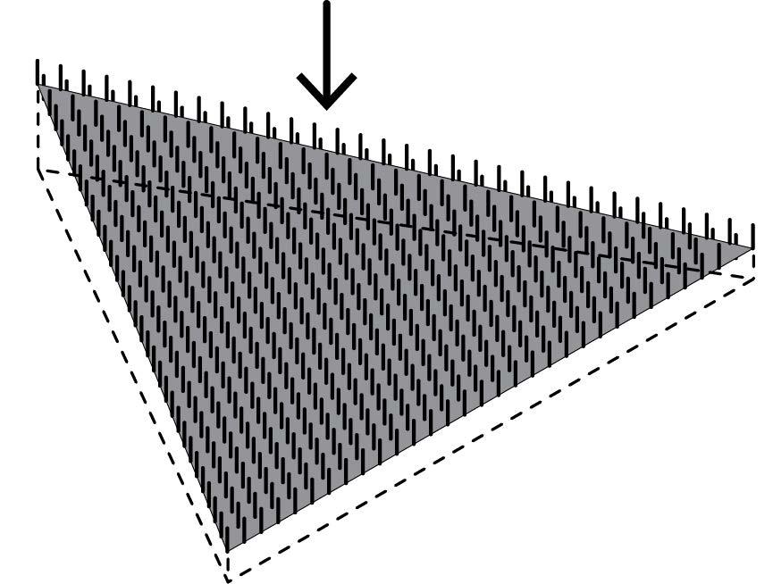
The supports are defined in the exterior and the inner layer, making sure that they don’t overlap with the boad.
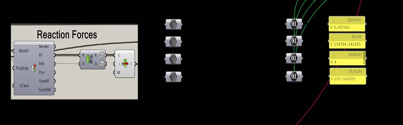
Karamba3D meausures the total Mass, the Maximum Dispacement and the Maximum Reaction Forces at the Fins.
 5.
5.
6.
6.
Using Karamba3D a mesh load is applied at the roof.
7.
5.
5.
6.
6.
Using Karamba3D a mesh load is applied at the roof.
7.
7.
8.
8.
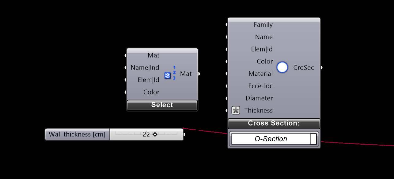
Parameters to Optimize
1. Radius of the cross-section
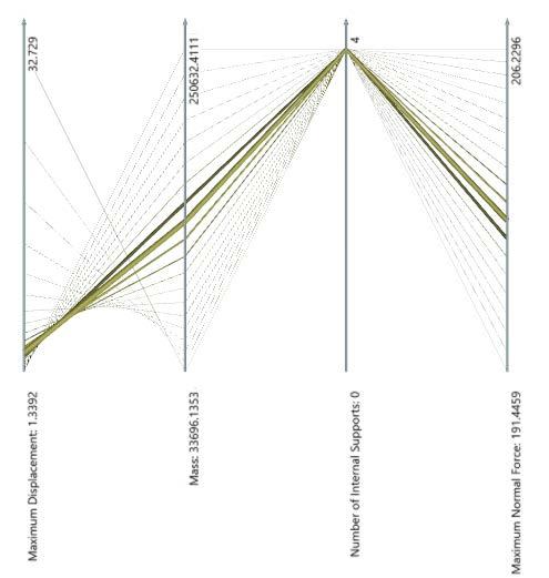
Objectives
The optimization algorithm aims to minimize the:
1. Maximum Dispacement
2. Mass
3. Maximum Reaction Force at the Fins
4. The amount of internal colums
0 Inner columns 0 Inner columns
4 Ixnner
2. The level of subdividing iterations for the 3D spaceframe that also define the amound of the inner colums (inner columns should not overlap with the boat.).
The selected solution represented in a MultiAxe using the Octopus add-on.
ROOF’S
SPACEFRAME STRUCTURAL OPTIMIZATION
2 Inner columns
The boundaries of Floor Plan was settled from the very early stage of the design processs as the architectural design did not change. A grid of 2.50 m was selected for the division of every side of the triangular plan. The 3.2 m grid corresponds to the dimension of the facade panels and the distances betwen the placement of the glass fins that are connected prerpendicular to the facade panels.
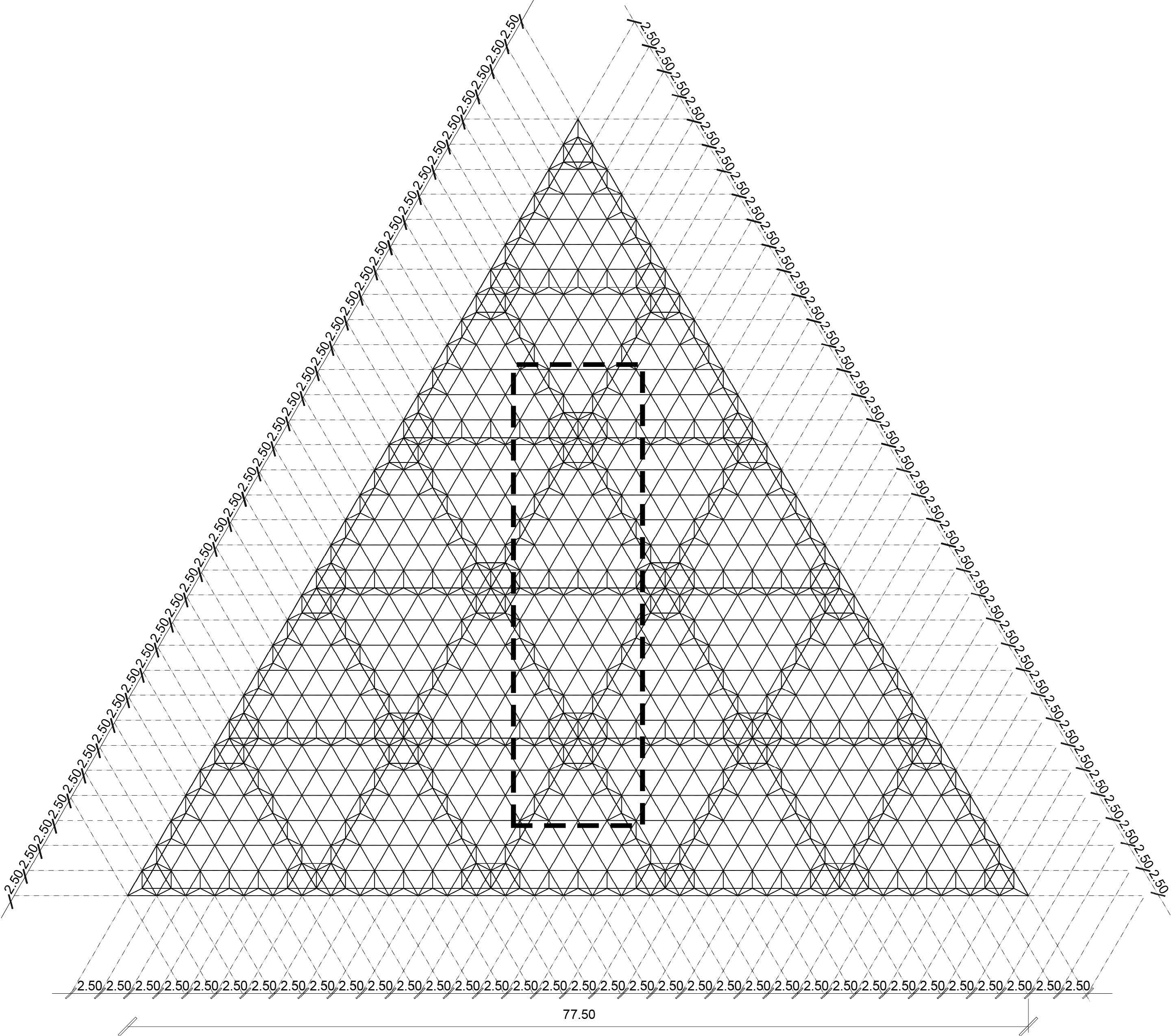
FINAL ROOF PLAN BOAT BOUNDARY
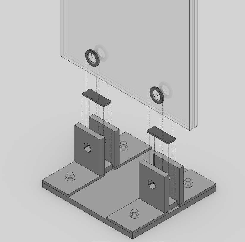
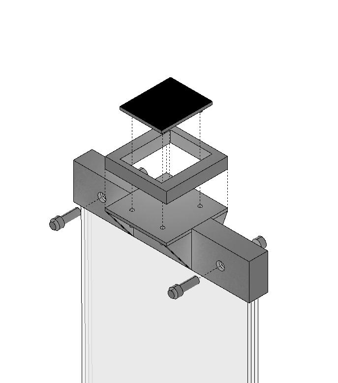
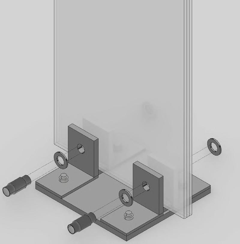
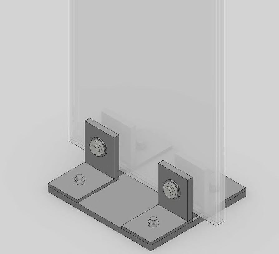
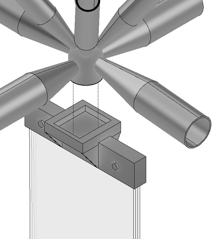
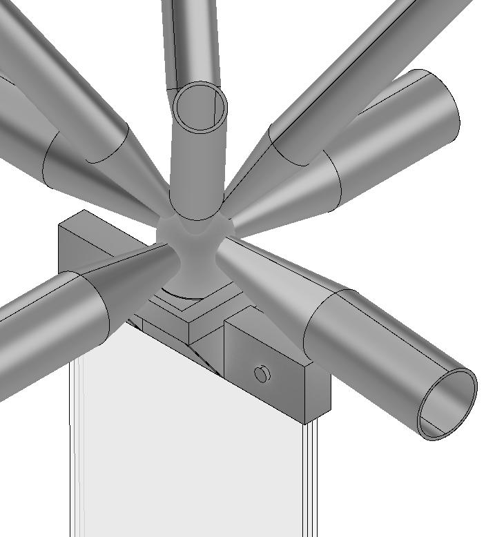
STRUCTURAL DETAILS 2. 2. 1. 1.
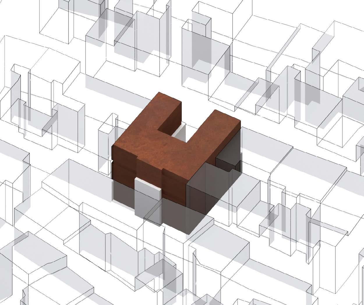
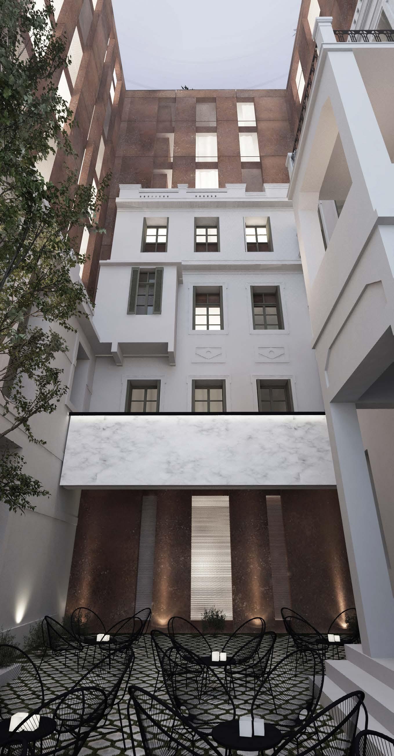
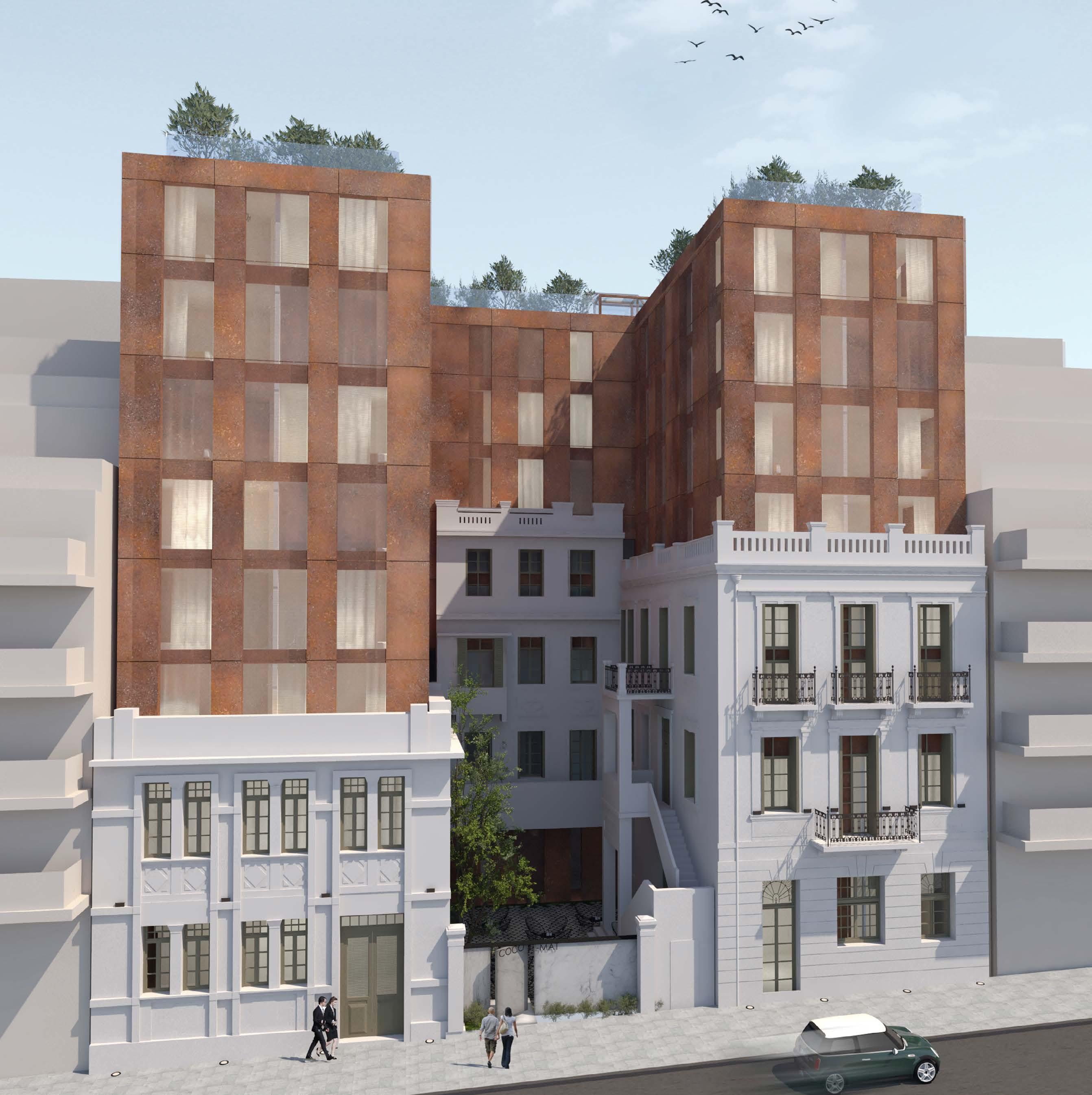
Cocomat Hotel
Conversion of a Parking Building to a Hotel
Type: Professional Project
Role: Senior Architect (ASPA KST)
Year: 2019
Author of Drawings: Stella Pavlidou
Software Used: Rhino3D, Autocad, Vray
Team: Stella Pavlidou, Zozo Koutsanellou
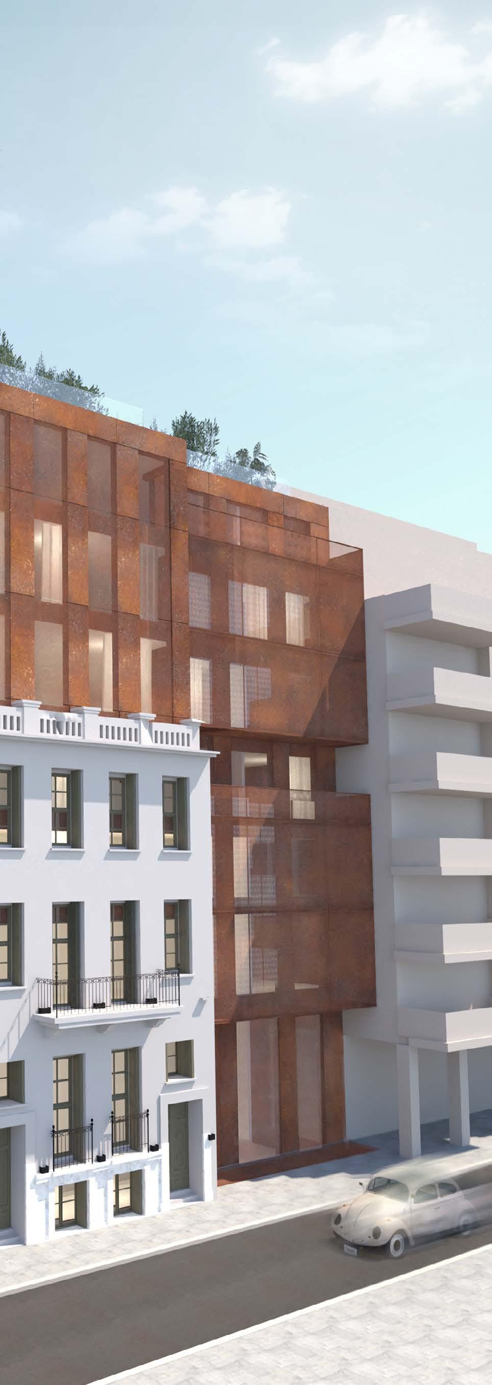
“This section presents drawings produced for the Cocomat Hotel in Athens, Greece. During this project.
I was involed as a Senior Architect from the first stages of measuring the building, design development and building permit. I was responsible for delivering detailed drawings, 3d models and filing permit documentation for the committee of preserved buildings. Throughtout this process I was in constant contact with the project’s clients, consultants, engineers and constructors working together on updating the design to the needed changes.”
03
An old Parking built on top of listed neoclassical has to be renovated and re-arranged inside. The new building will accommodate a hotel of 129 rooms and 259 beds. The main design principles are the following:
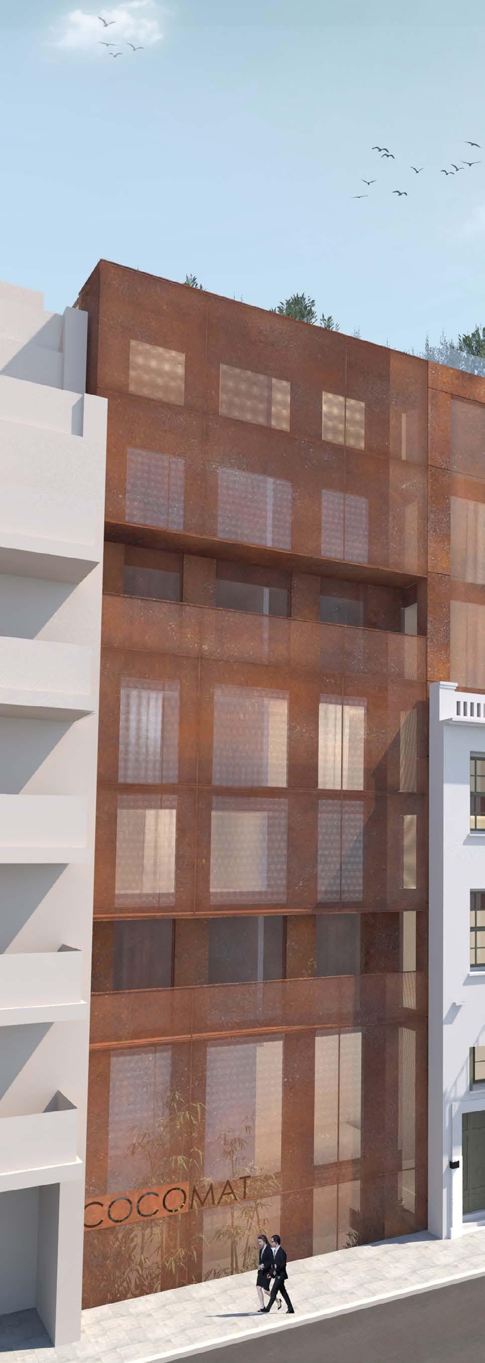
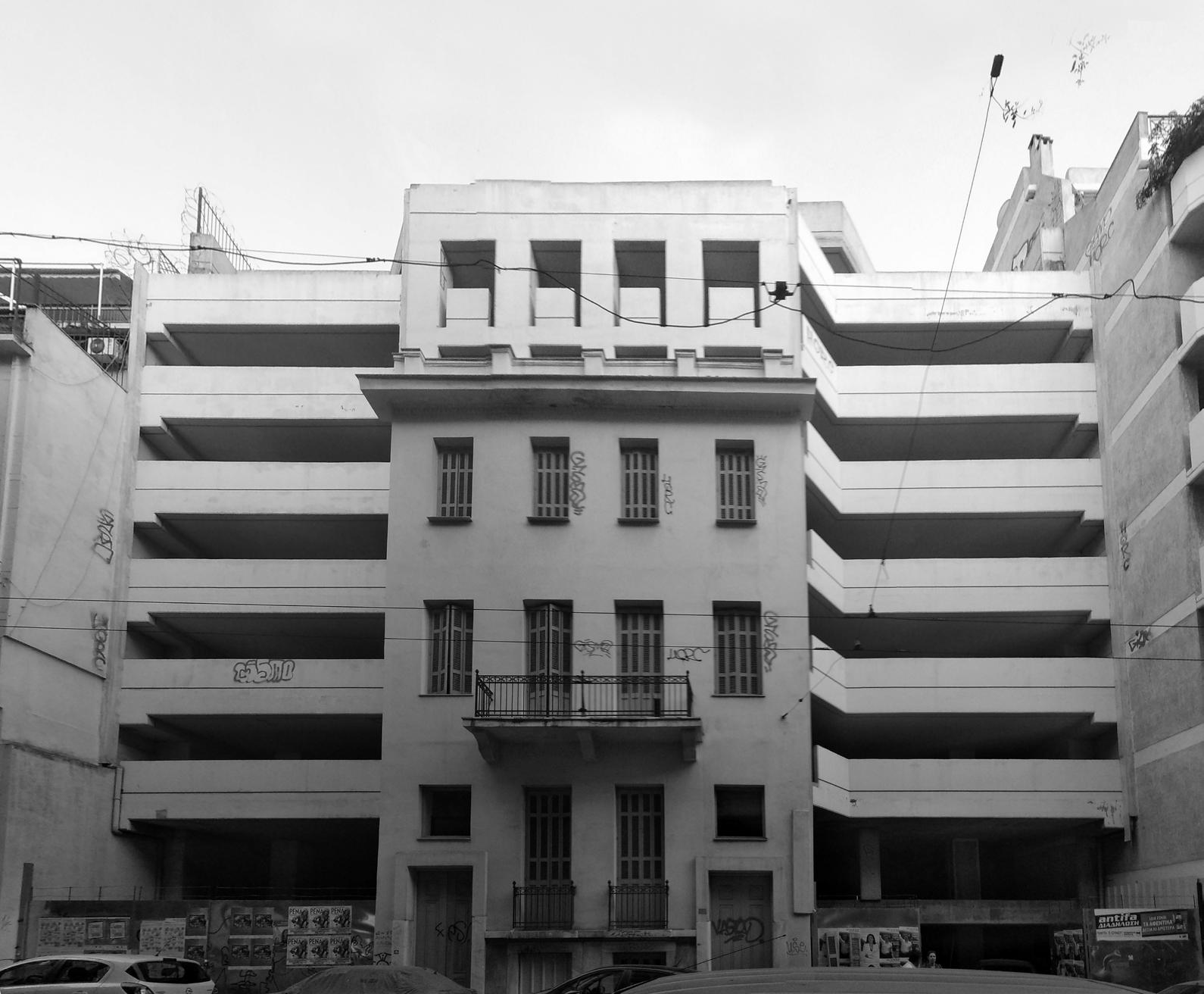
-Integration of the preserved elements into the new building.
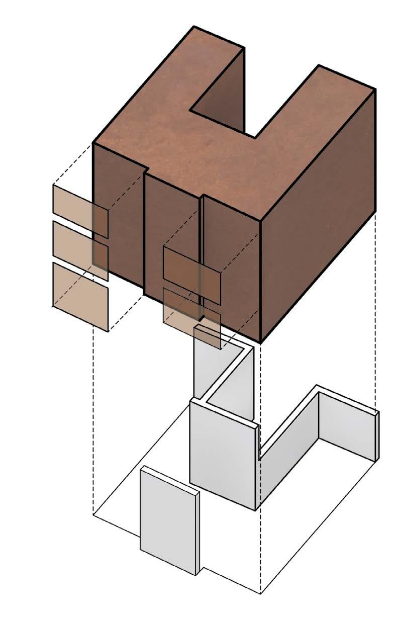
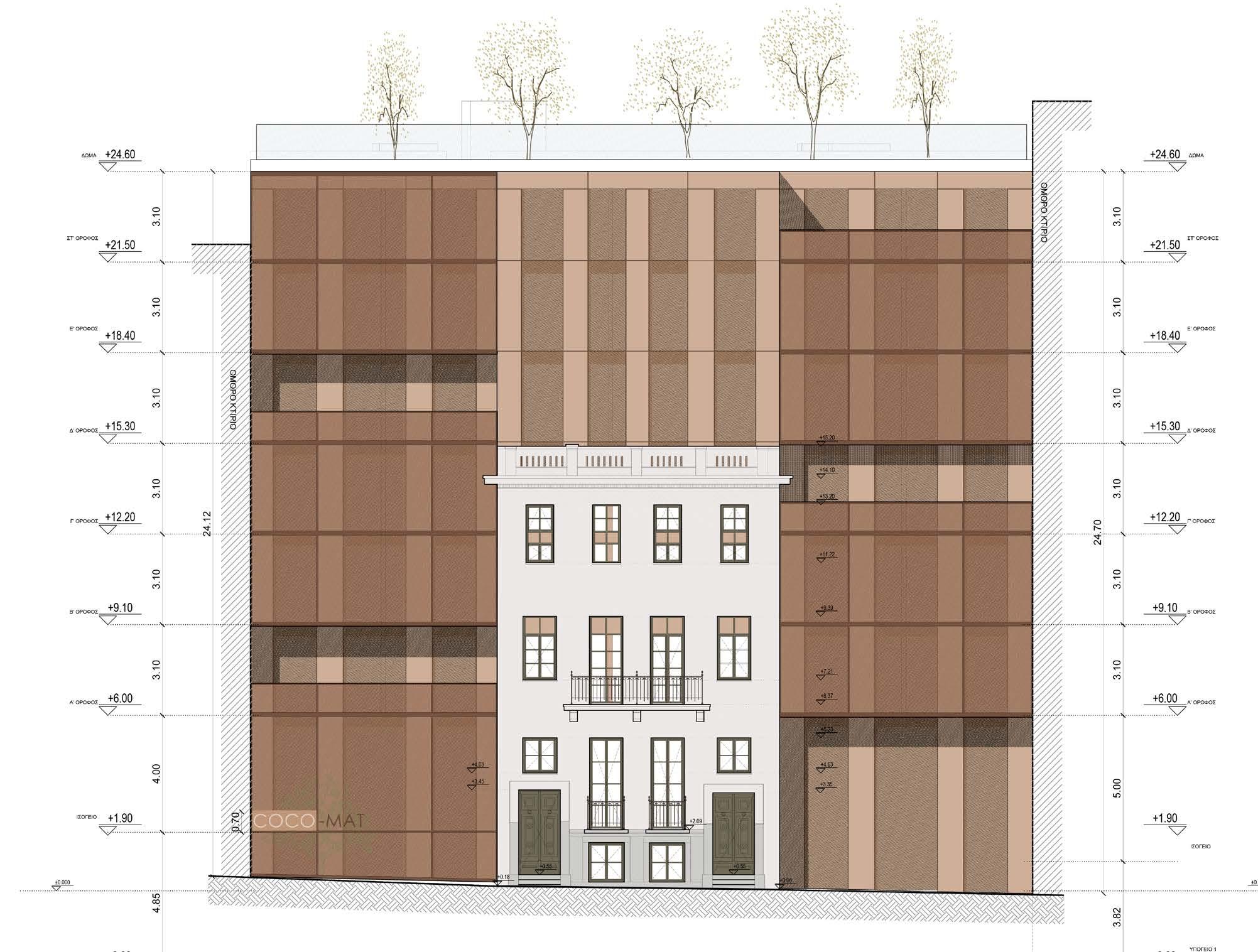
-Restoration of all preserved facades.
-Facade treatment of the new building to match harmoniously with the preserved facades.organization and the structural reinforcement.
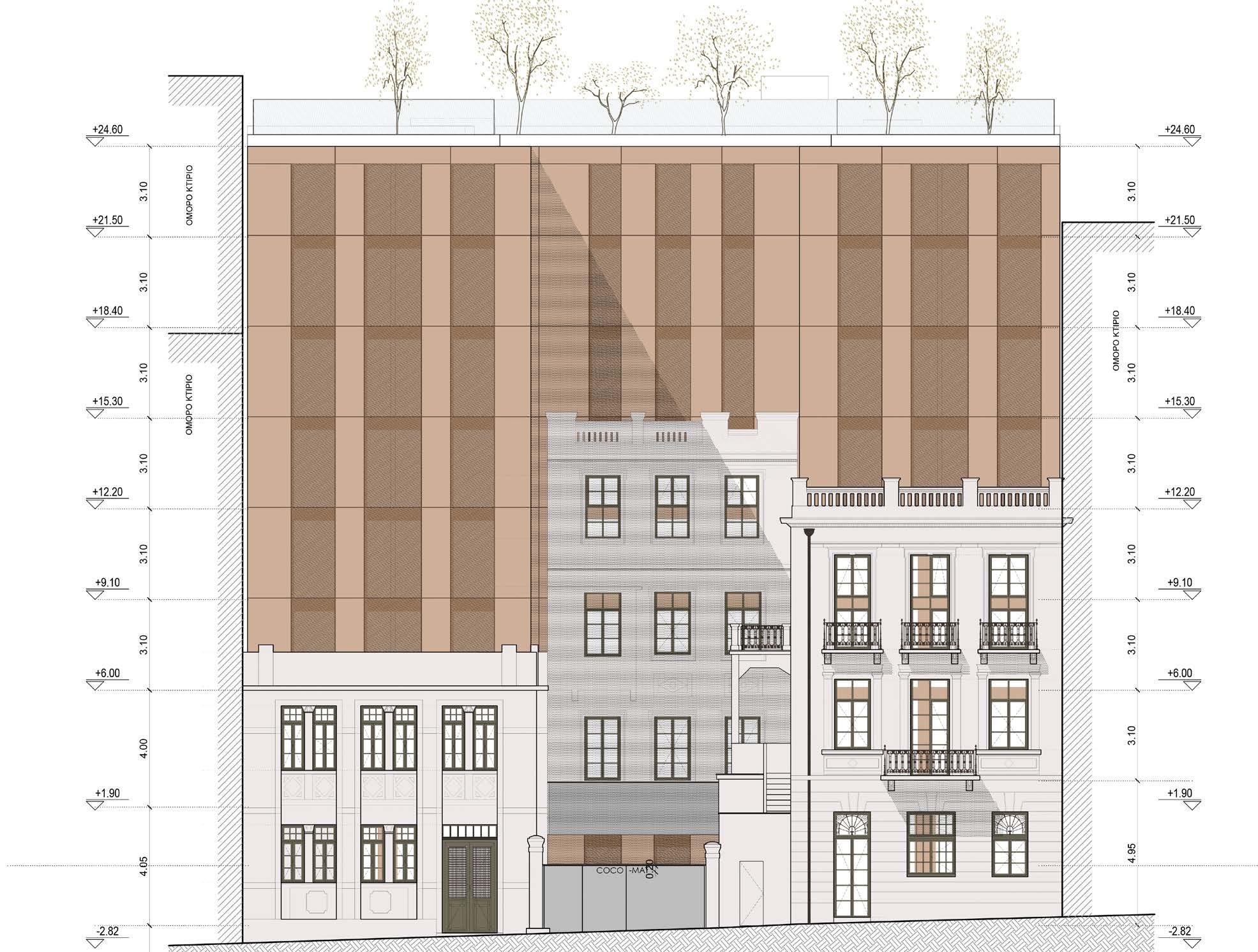
FRONT ELEVATION
HORIZONTAL SECTION
BACK ELEVATION
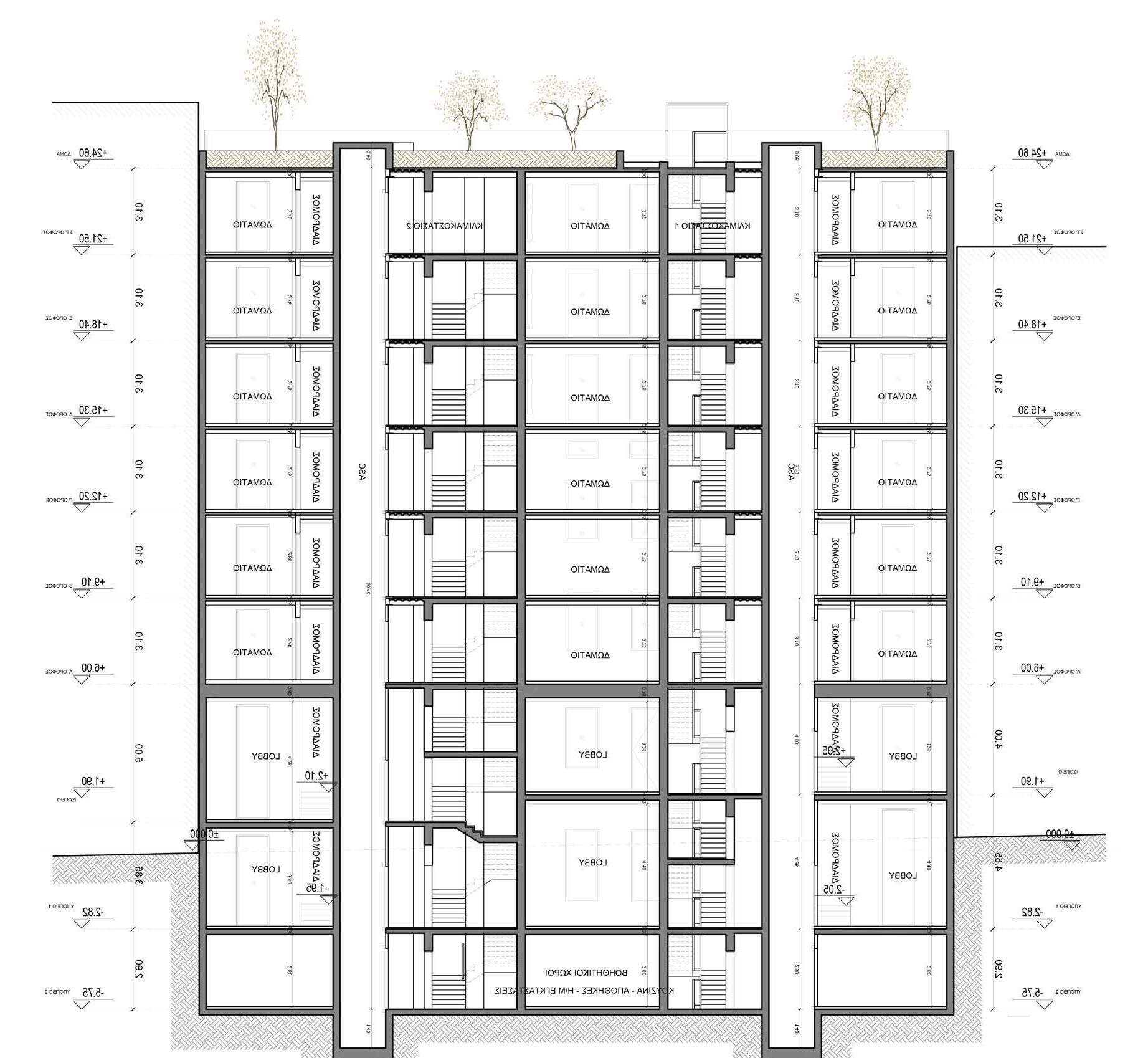
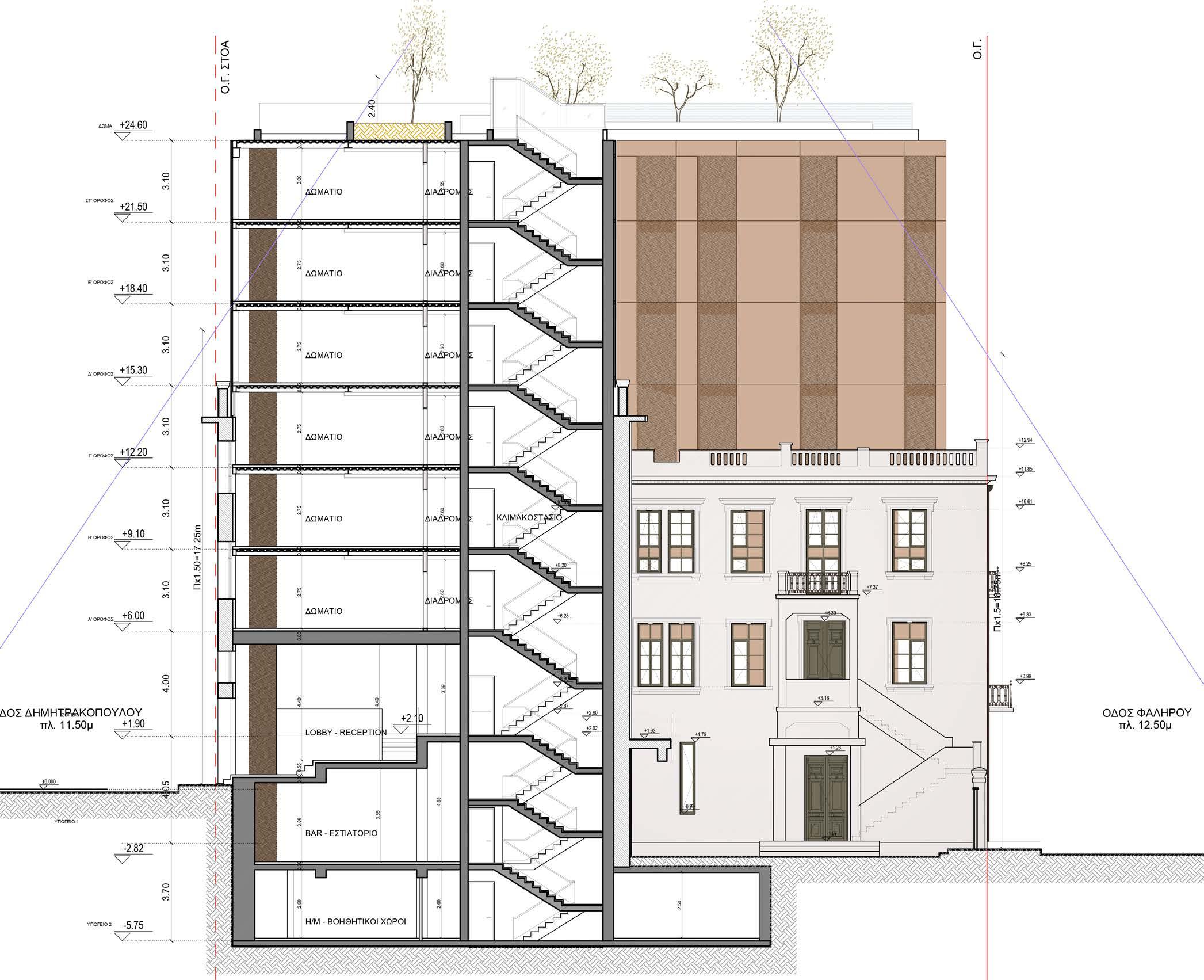
VERTICAL SECTION
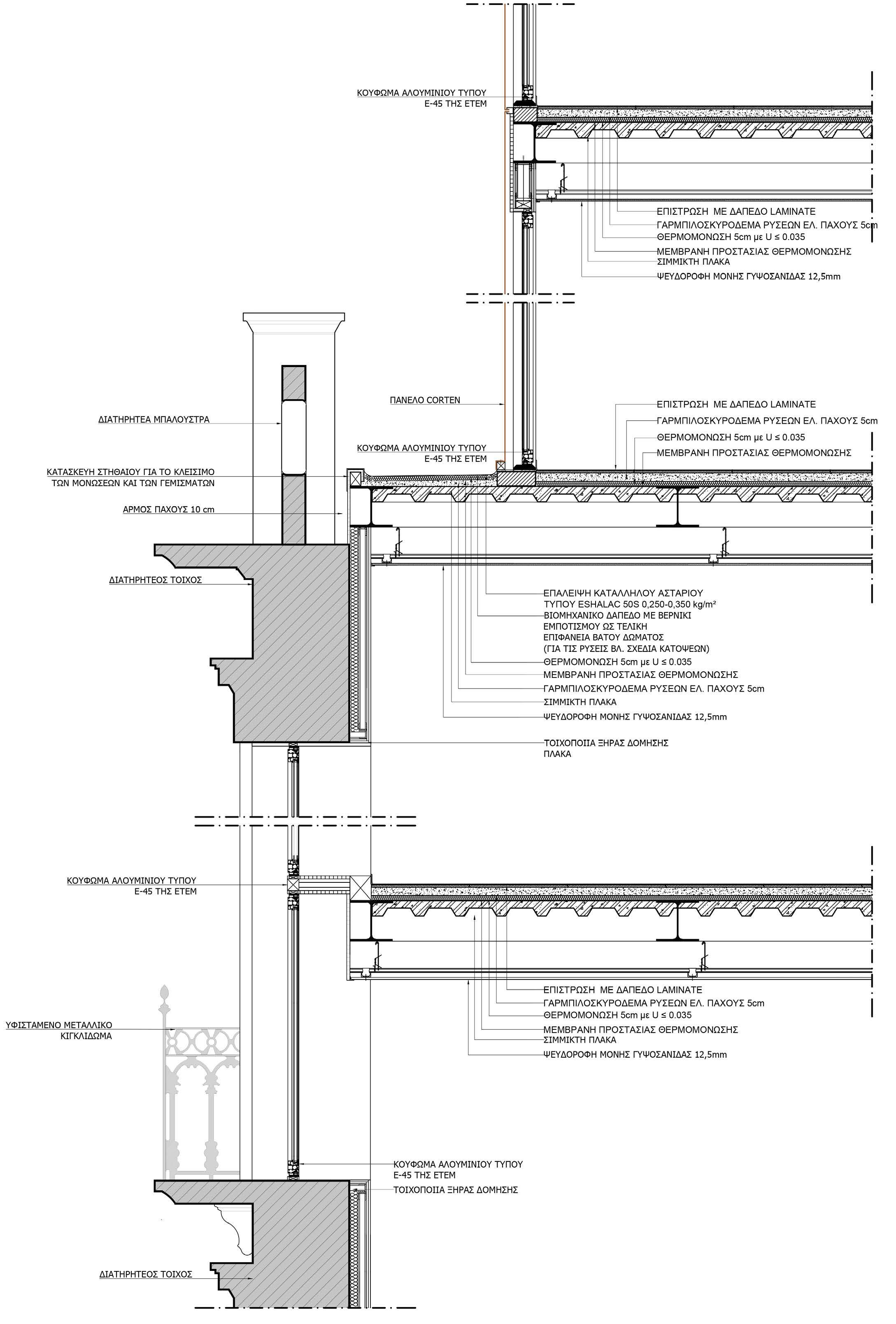
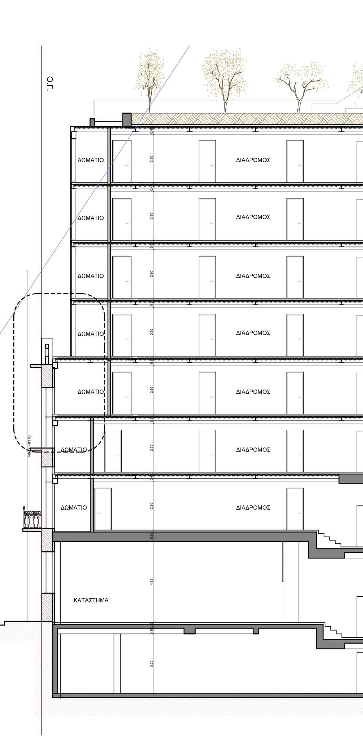
DETAIL SECTION
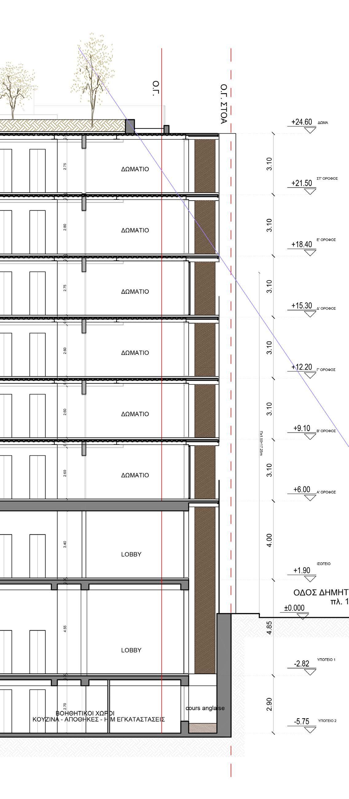
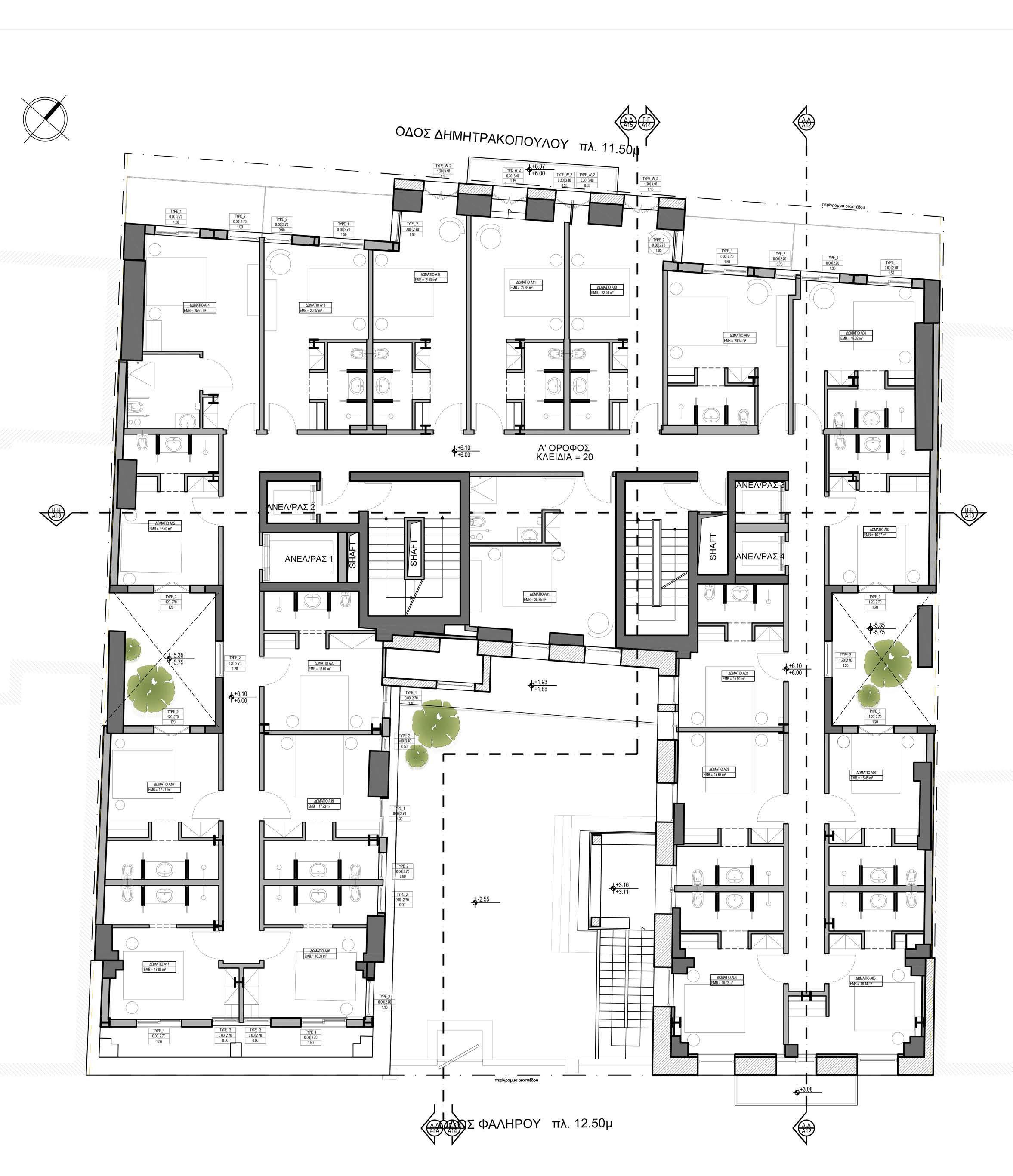
VERTICAL SECTION TYPICAL FLOOR PLAN
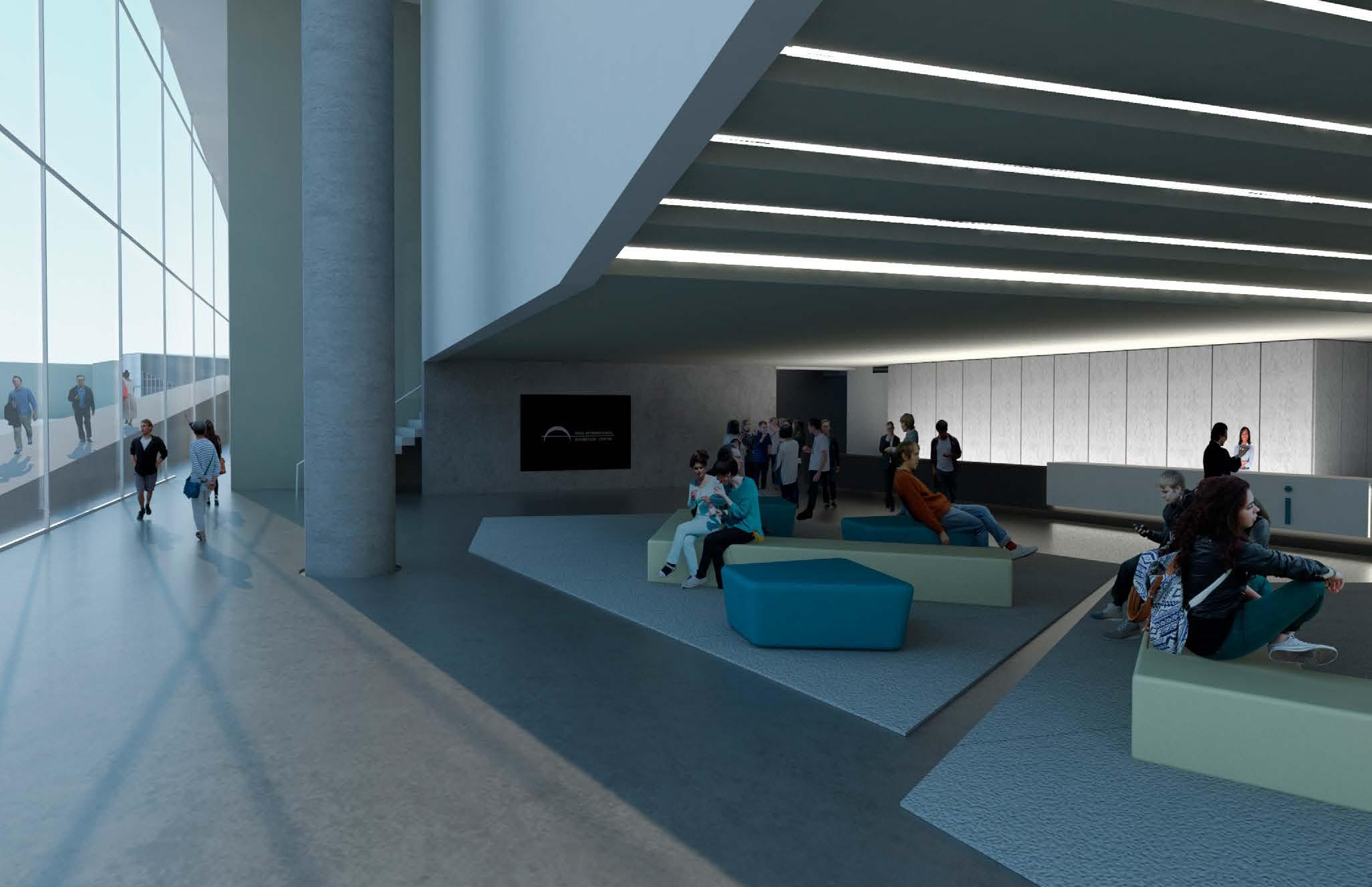
Kip Calm and go to the expo centre
Addition to Riga Expo Centre
Type: Competition Entry
Team: Stella Pavlidou, Ismini Theodosopoulou
Year: 2017
Author of selected drawings: Stella Pavlidou
Software Used: Rhino3D, Vray, Photoshop, Autodesk 3Ds Max
“This section presents selected drawings from a competition entry along in 2017 for Bee Breeders. The task was to suggest an extension of the Riga Expo Centre that includes selected uses. The design was developped from two team members.”
04
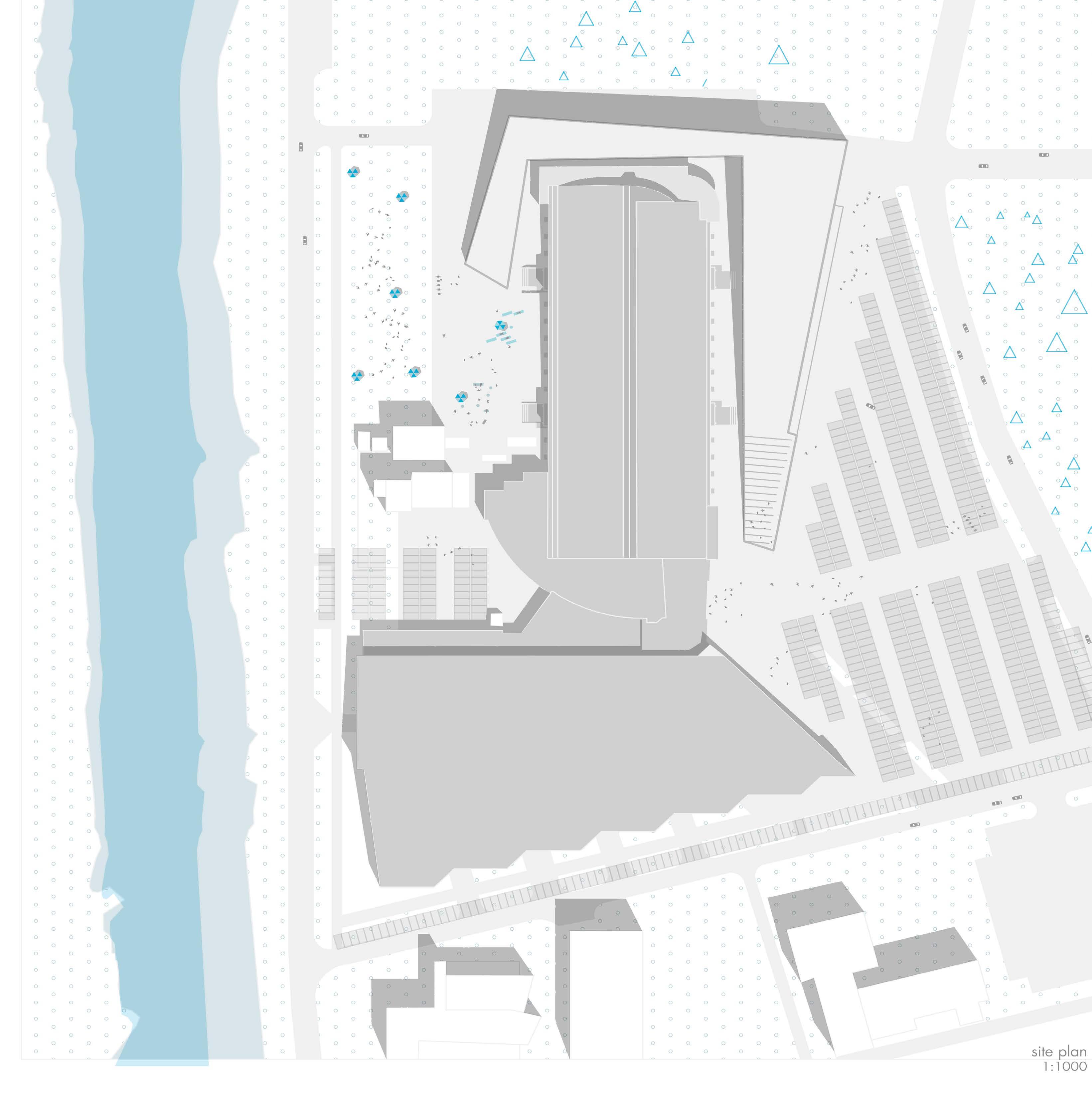
Project Description:
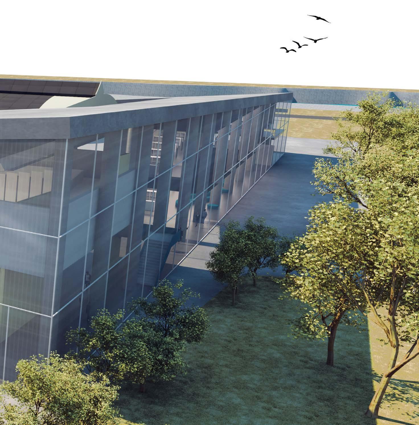
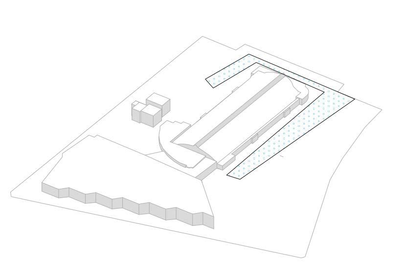
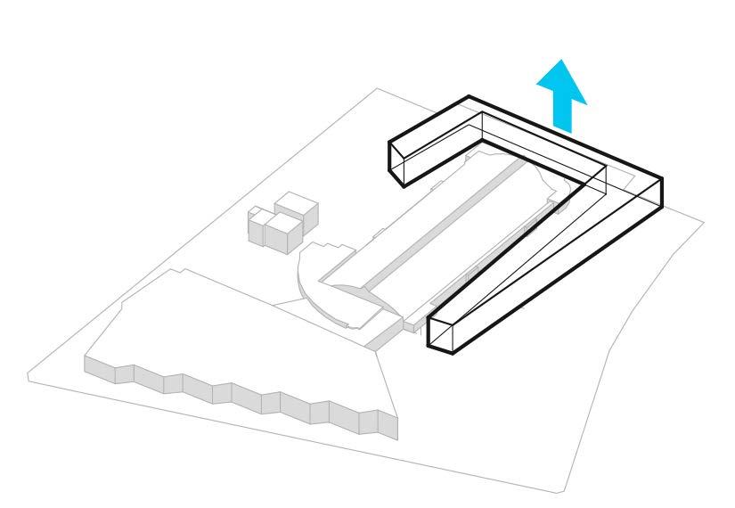
The site is of particular interest, located next to the historical Old City and Business Centre of Riga. The existing building is placed in the center of the site, dividing it in two parts. Our intention is to connect the two sides through a volume that emerges from the ground.
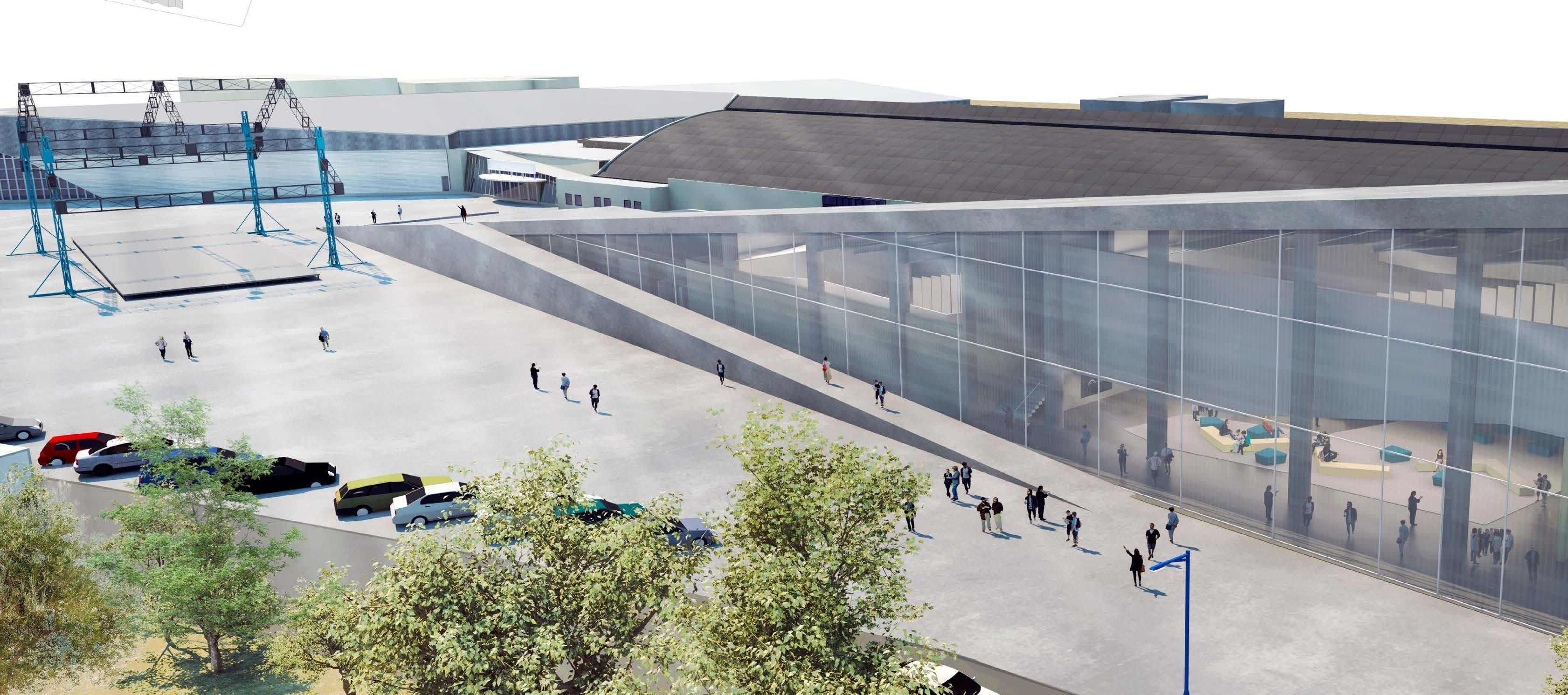
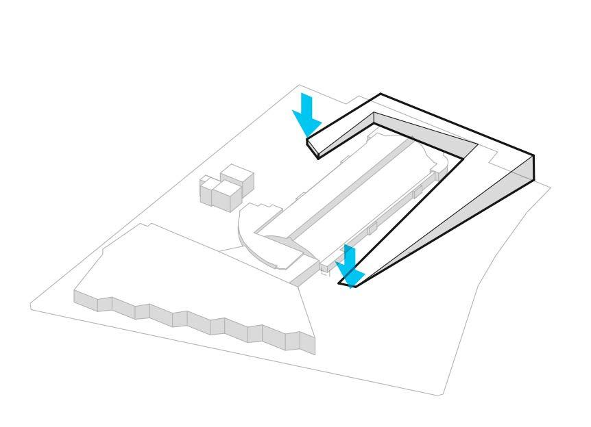
The new addition mimics the shape of an
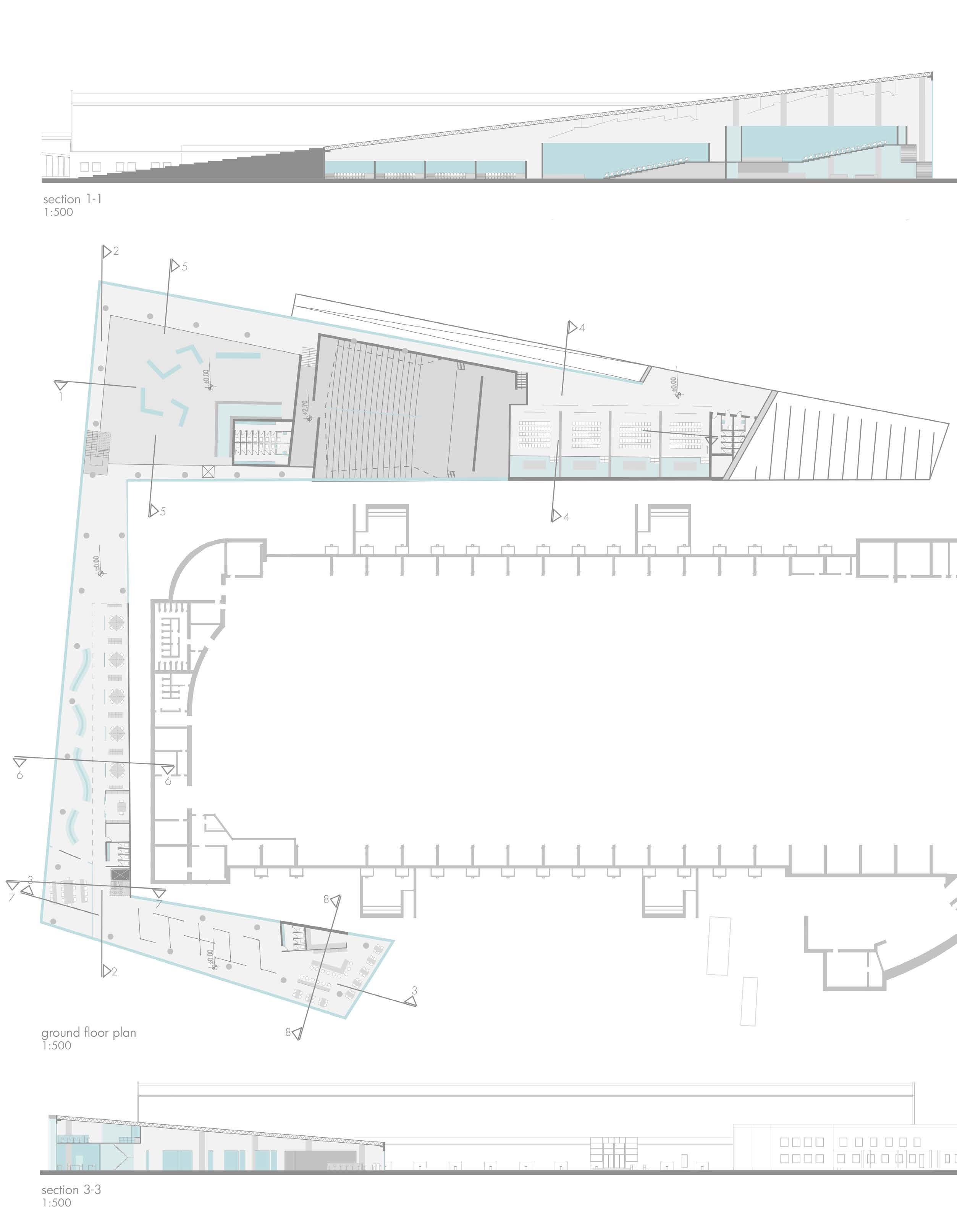
origami, embracing the existing building. The inner circulation allows the visitor entering from the streetide to reach the riverside. Its transparency forms bright spaces, ideal for ehibitions as well as for working environment, providing the visitors with multiple views of the site. In addition, the ramp of the outer shell allows a broad perspective of the area.
The visitor enters the building to find the
lobby. From there, they can either visit the auditorium s and conference rooms, or continue to the management offices and then to the exhibition space and cafe.

Restoring the Path
Designing a new Research Center at the ruins of an old mining
Type: Academic Project
Supervisor: Prof. Athanasios Spanomaridis
Year: 2015
Author of Drawings: Stella Pavlidou
Software Used: Rhino3D, Autocad, Vray, Photoshop
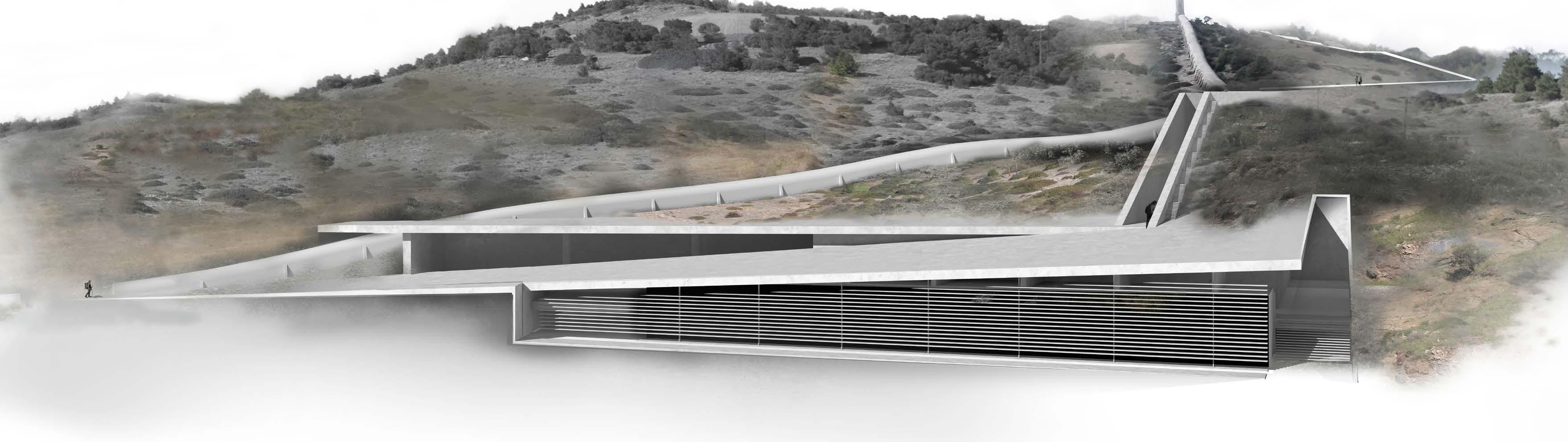
“This section presents selected drawings of my Graduation Thesis in 2015 from the Architecture Departement of the University of Patras, in Greece. The aim of this project is to bring to mind the history of the lanscape, by restoring the path of an old chimney. Landmarks connect through the path of an old chimney and a proposed research center.”
05
Project Description:
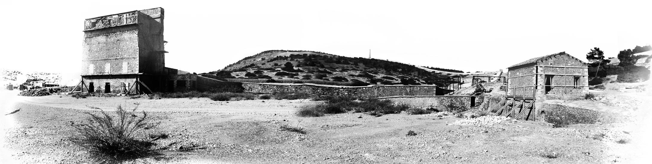
The aim of this project is the design of a research center in the city of Lavrion. Lavrion, whose name derives from the word Lavra (tunnel in Greek) is known for its mining activity. In the 19th century two mining industries were founded, the Greek and French company. After the de-industrialization of Greece, Lavrion was deserted by its inhabitants and workers, left with just the remains of both companies.
In the 1980s the National Technical University of Athens proposed the creation of a technological and cultural park where the French company was once. Nowadays, the Lavrion Technological and Cultural Park contributes significantly to the cultural development of Lavrion
Lavrion is of particular interest to researchers from various sciences but lacks of temporary residences which force them to stay at the surrounding areas.
This thesis suggests the creation of a Research Center that will provide temporary housing for some researchers as well as laboratory areas.
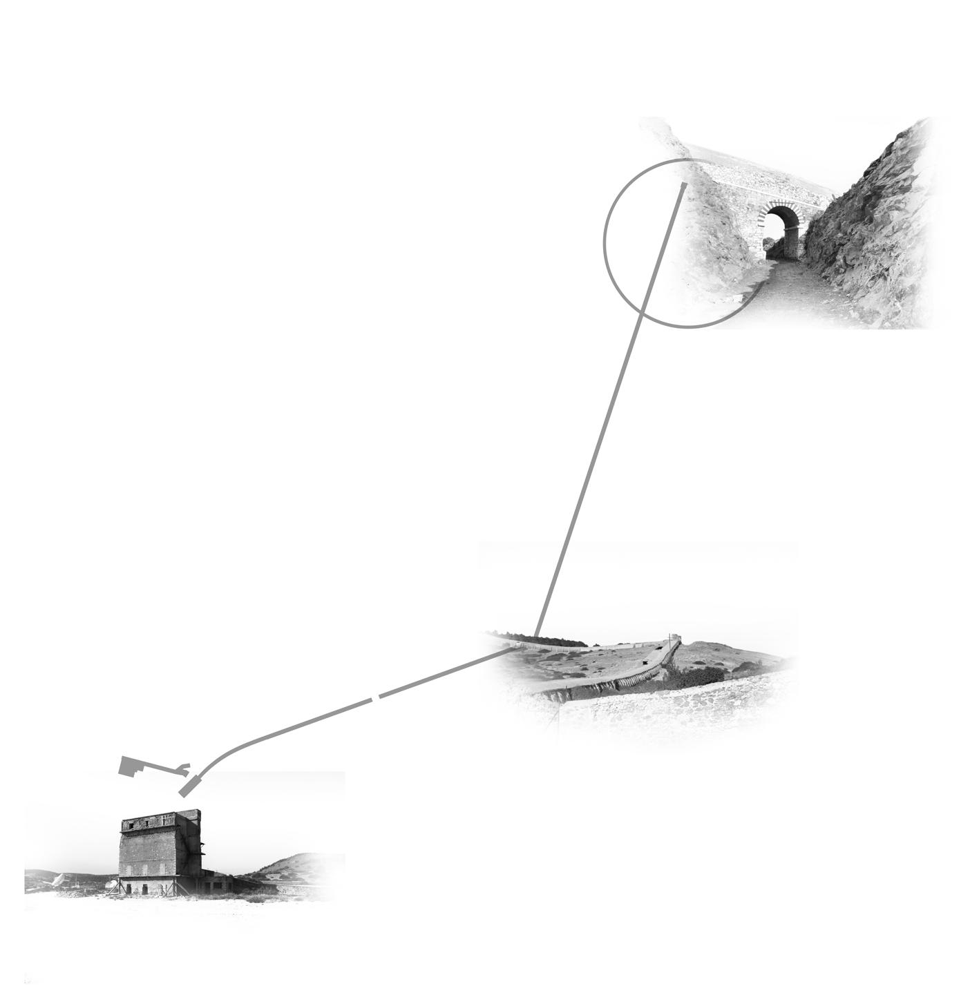
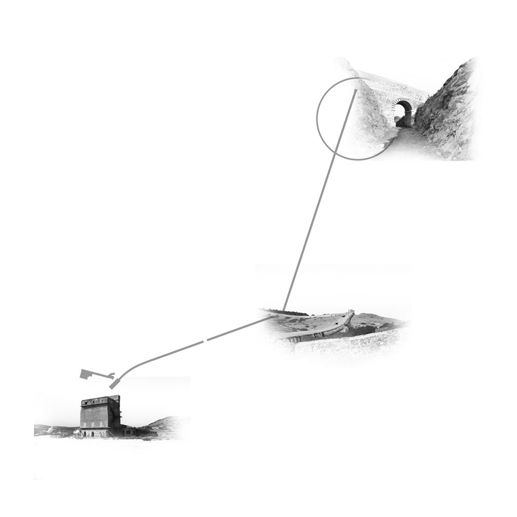
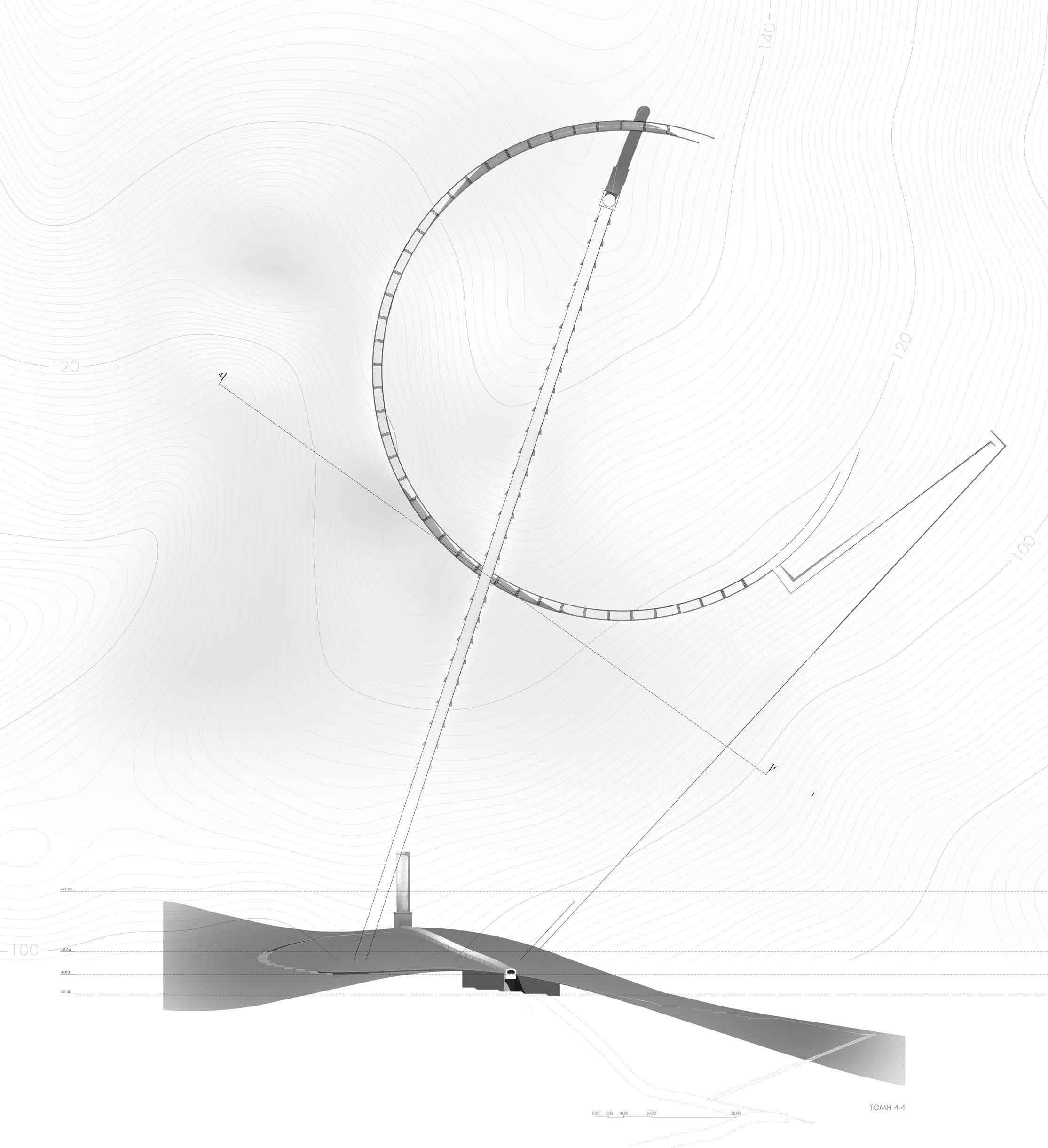
The area chosen for the construction of the Center is in a hill that has three main sections:
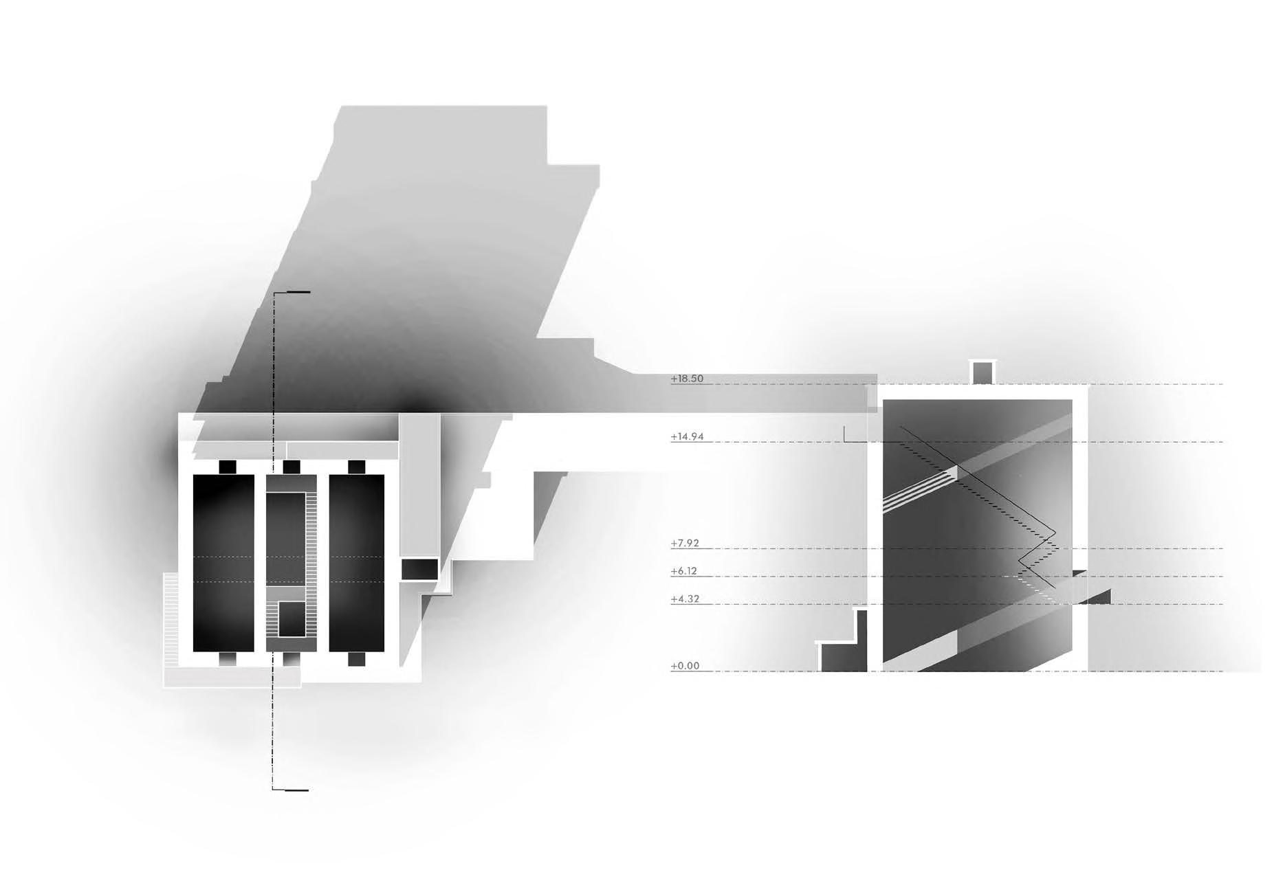
1. The building of Konofagos used by the French company to trap and filter the toxic gases.
2. The flue pipe
3. The hilltop, where the flue pipe ends, that served to transfer materials from the surrounding areas to the French
company.
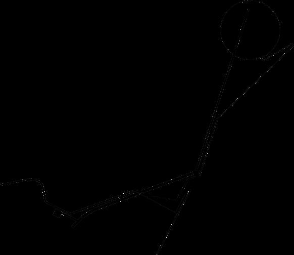
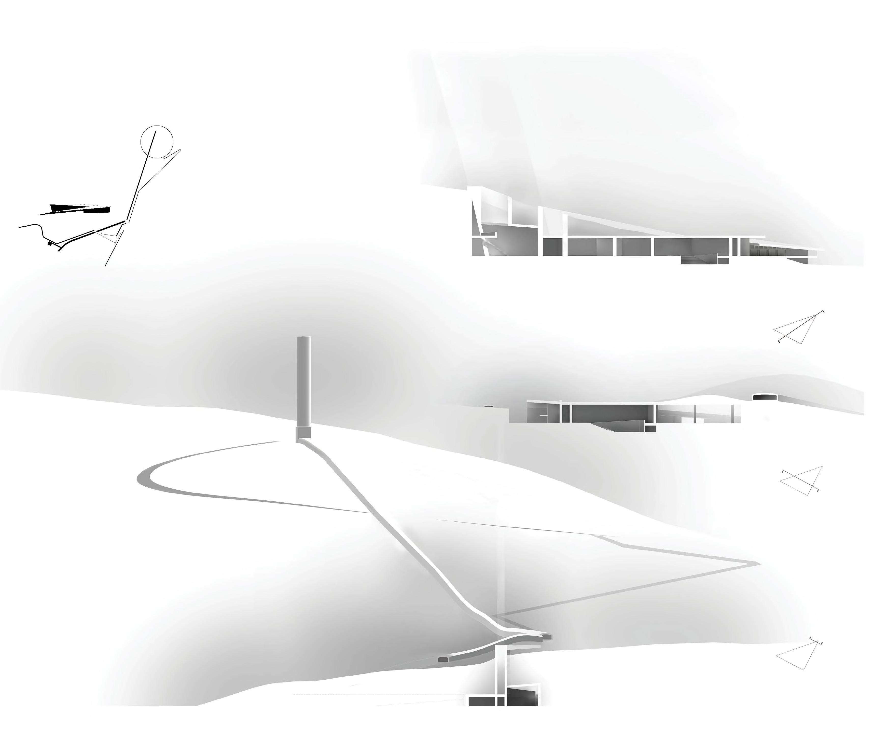
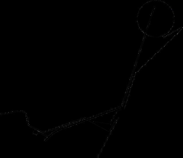
The proposal suggests a path that connects the Research center with the building of Konofagos and the hilltop through a path that follows the form of the flue pipe.
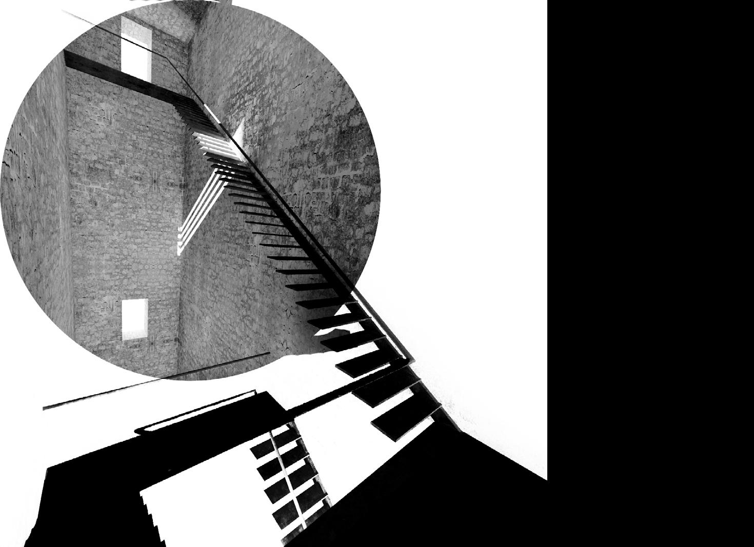
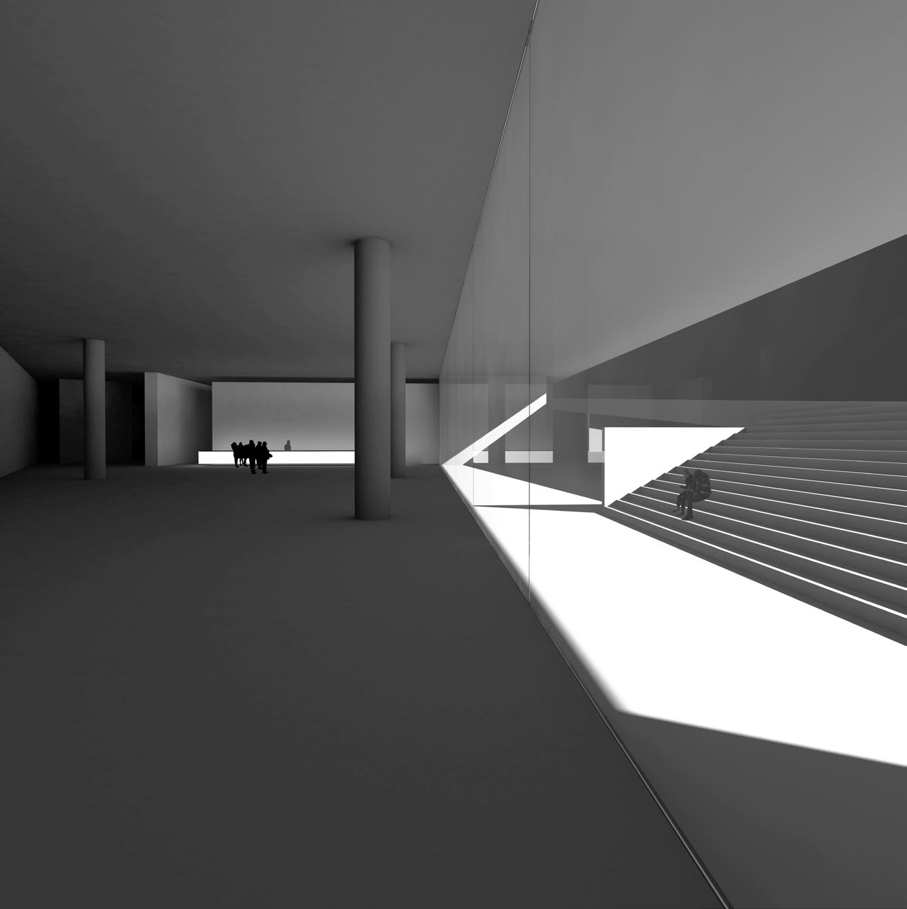
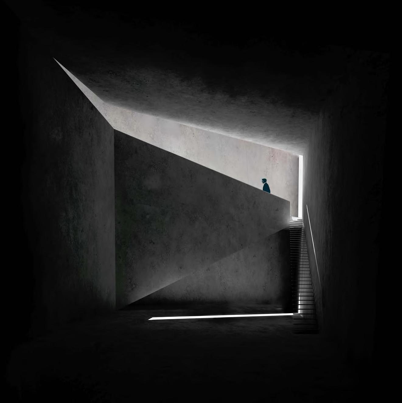
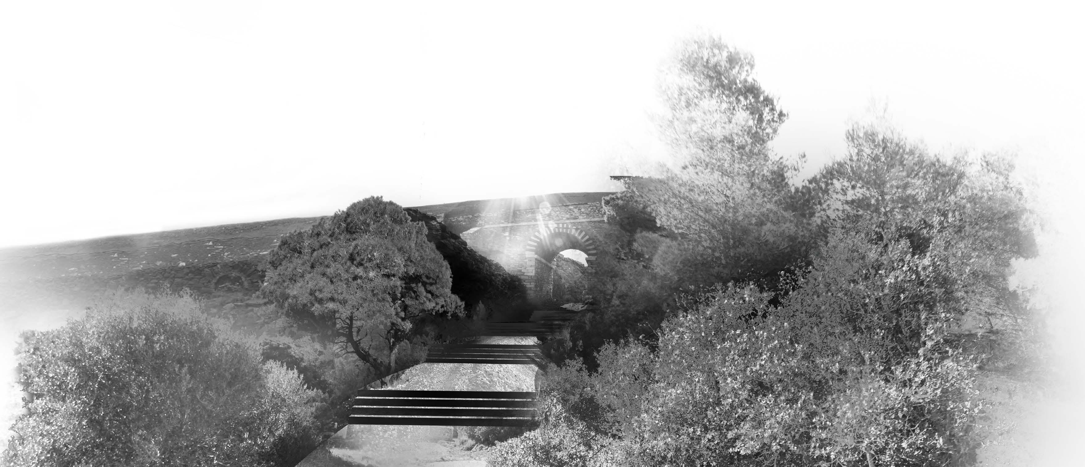
The route starts from the building of Konofagos that represents the last stage of the industrial activities. An inside staircase allows viewing the research center and the hilltop.
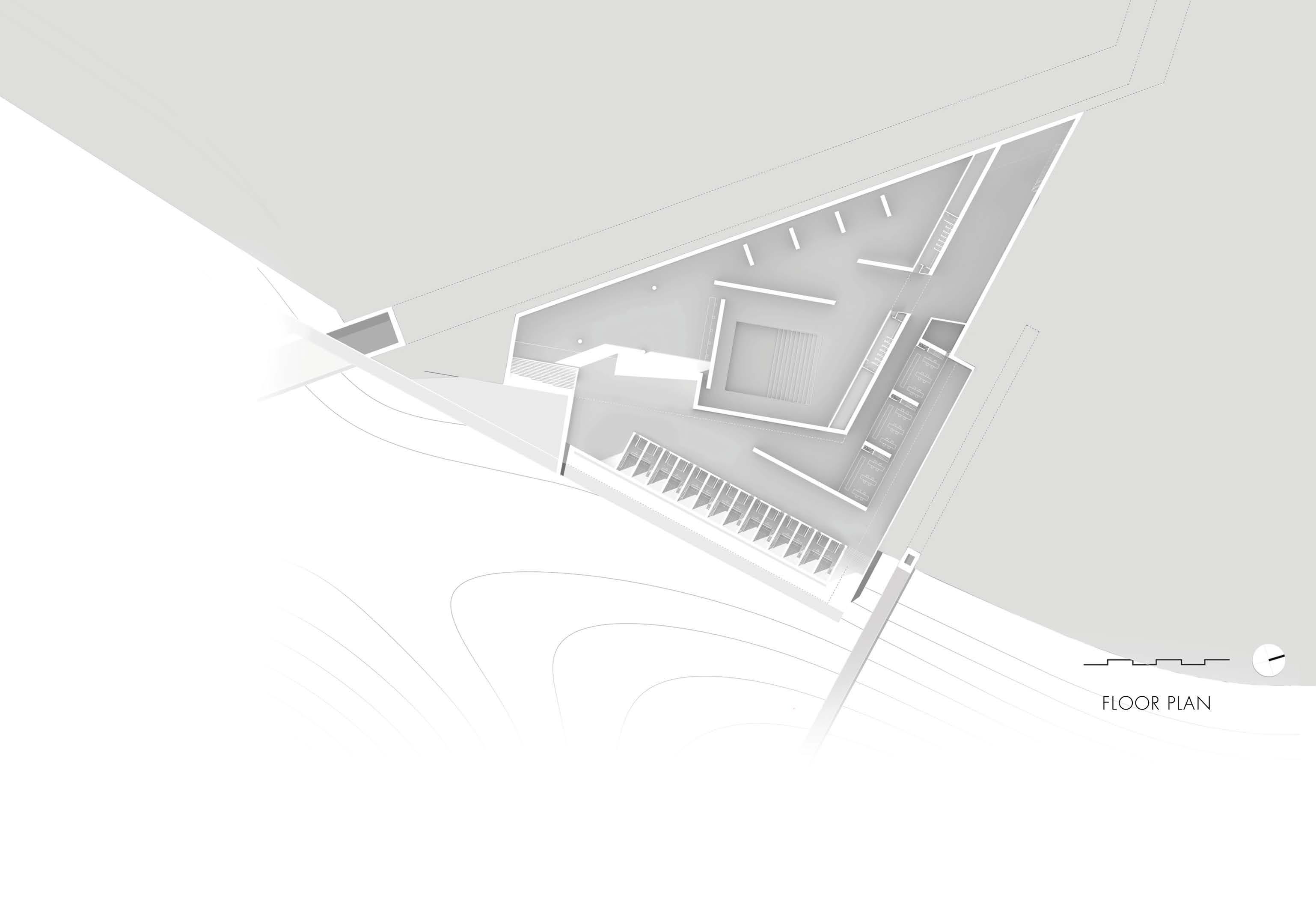
Following the flue pipe and passing through a rift the visitors arrive at the Research Center, The roof of the building is part of the path.
The last point of the path is at the hilltop where the existed circular route, used by the mining company, is hightlighted.

KONOFAGOS
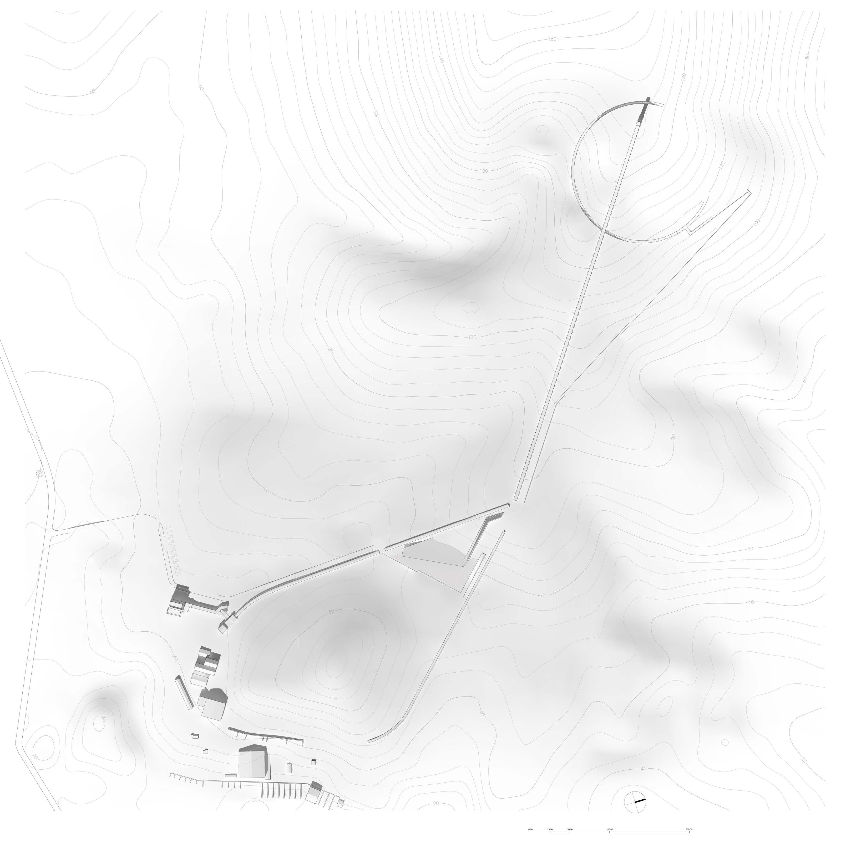
TOP PLAN
The route starts from the building of Konofagos that represents the last stage of the industrial activities. An inside staircase allows viewing the research center and the hilltop.
1
Following the flue pipe and passing through a rift the visitors arrive at the Research Center, The roof of the building is part of the path.
2
The last point of the path is at the hilltop where the existed circular route, used by the mining company, is hightlighted.
3
