
PROBLEM 2.1
Chapter 2
STEADY STATE CONDUCTION
A plane wall, 7.5 cm thick, generates heat internally at the rate of 105 W/m3. One side of the wall is insulated, and the other side is exposed to an environment at 90°C. The convection heat transfer coefficient between the wall and the environment is 500 W/(m2 K). If the thermal conductivity of the wall is 12 W/(m K), calculate the maximum temperature in the wall.
GIVEN
Plane wall with internal heat generation
Thickness (L) = 7.5 cm = 0.075 m
Internal heat generation rate ( Gq ) = 105 W/m3
One side is insulated
Ambient temperature on the other side (T) = 90 °C
Convective heat transfer coefficient ( ch ) = 500 W/(m2 K)
Thermal conductivity (k) = 12 W/(m K)
FIND
The maximum temperature in the wall (Tmax)
ASSUMPTIONS
The heat loss through the insulation is negligible
The system has reached steady state
One dimensional conduction through the wall
SKETCH
SOLUTION
The one dimensional conduction equation, given in Equation (2.5), is k 2 2 T x + Gq = c T t
For steady state, T t = 0 therefore k 2 2 dT dx + Gq = 0
This is subject to the following boundary conditions
No heat loss through the insulation dT
= 0 at x = 0
Convection at the other surface
Integrating the conduction equation once
q k + C
C1 can be evaluated using the first boundary condition
Integrating again
The expression for T and its first derivative can be substituted into the second boundary condition to evaluate the constant C
Substituting this into the expression for T yields the temperature distribution in the wall
PROBLEM 2.2
A small dam, which may be idealized by a large slab 1.2 m thick, is to be completely poured in a short period of time. The hydration of the concrete results in the equivalent of a distributed source of constant strength of 100 W/m3. If both dam surfaces are at 16°C, determine the maximum temperature to which the concrete will be subjected, assuming steady-state conditions. The thermal conductivity of the wet concrete may be taken as 0.84 W/(m K).
GIVEN
Large slab with internal heat generation
Internal heat generation rate ( Gq ) = 100 W/m3
Both surface temperatures (Ts) = 16°C
Thermal conductivity (k) = 0.84 W/(m K)
FIND
The maximum temperature (Tmax)
ASSUMPTIONS
Steady state conditions prevail
SKETCH
SOLUTION
The dam is symmetric. Therefore, x will be measured from the centerline of the dam. The equation for one dimensional conduction is given by Equation (2.5) k
For steady state, T t = 0 therefore k 2 2 dT dx + Gq = 0
This is subject to the following boundary conditions
1. By symmetry, dT/dx = 0 at x = o
2. T = Ts at x = L
Also note that for this problem Gq is a constant. Integrating the conduction equation
Integrating once again
dT
dx = –Gq k x + C1
The constant C1 can be evaluated using the first boundary condition
0 = –Gq k (0) + C1 C1 = 0
T = 2 Gq k x2 + C2
The constant C2 can be evaluated using the second boundary condition
Ts = 2 Gq k L2 + C2 C2 = Ts + 2 Gq k L2
Therefore, the temperature distribution in the dam is
T = Ts + 2 Gq k (L2 – x2)
The maximum temperature occurs at x = 0
Tmax = Ts + 2 Gq k (L2 – (0)2) = 16°C + 3100W/m 2[0.84W/(m K)] (0.6 m)2 = 37°C
COMMENTS
This problem is simplified significantly by choosing x = 0 at the centerline and taking advantage of the problem’s symmetry.
For a more complete analysis, the change in thermal conductivity with temperature and moisture content should be measured. The system could then be analyzed by numerical methods discussed in chapter 4
PROBLEM 2.3
The shield of a nuclear reactor is idealized by a large 25 cm thick flat plate having a thermal conductivity of 3.5 W/(m K). Radiation from the interior of the reactor penetrates the shield and there produces heat generation that decreases exponentially from a value of 187.6 kW/ m3. at the inner surface to a value of 18.76 kW/m3 at a distance of 12.5 cm from the interior surface. If the exterior surface is kept at 38°C by forced convection, determine the temperature at the inner surface of the shield. Hint: First set up the differential equation for a system in which the heat generation rate varies according to q (x) = q (0)e –Cx .
GIVEN
Large flat plate with non-uniform internal heat generation
Thickness (L) = 25 cm=0.25 m
Thermal conductivity (k) = 3.5 W/(m K)
Exterior surface temperature (To) = 38°C
Heat generation is exponential with values of
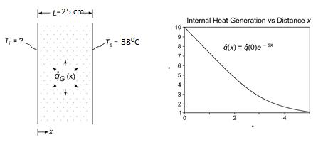
187.6 kW/m3 at the inner surface
18.76 kW/m3 at 12.5 cm from the inner surface
FIND
The inner surface temperature (Ti)
ASSUMPTIONS
One dimensional, steady state conduction
The thermal conductivity is constant
No heat transfer at the inner surface of the shield
From the hint, the internal heat generation is
The one dimensional conduction equation is given by Equation (2.5)
PROBLEM 2.4
A plane wall 15 cm thick has a thermal conductivity given by the relation
k = 2.0 + 0.0005 T W/(m K) where T is in degrees Kelvin. If one surface of this wall is maintained at 150 °C and the other at 50 °C, determine the rate of heat transfer per square meter. Sketch the temperature distribution through the wall.
GIVEN
A plane wall
Thickness (L) = 15 cm = 0.15 m
Thermal conductivity (k) = 2.0 + 0.0005 T W/(m K) (with T in Kelvin)
Surface temperatures: Th = 150 °C Tc = 50 °C
FIND
(a) The rate of heat transfer per square meter (q/A)
(b) The temperature distribution through the wall
ASSUMPTIONS
The wall has reached steady state Conduction occurs in one dimension
SKETCH
SOLUTION
Simplifying Equation (2.2) for steady state conduction with no internal heat generation but allowing for the variation of thermal conductivity with temperature yields
ddT k
dxdx = 0
with boundary conditions: T = 423 K at x = 0
T = 323 K at x = 0.15 m
The rate of heat transfer does not vary with x
– k dT dx = q A = constant
– (2.0 + 0.0005T) dT = q A dx
Integrating
2.0T + 0.00025 T 2 = –q A x + C
The constant can be evaluated using the first boundary condition
2.0 (423) + 0.00025 (423)2 = C –q A (0) C = 890.7
(a) The rate of heat transfer can be evaluated using the second boundary condition:
2.0 (323) + 0.00025 (323)2 = 890.7 –q A (0.15 m) qk = 1457 W/m2
(b) Therefore, the temperature distribution is 0.00025 T 2 + 2.0 T = 890.7 – 1458 x
COMMENTS
Notice that although the temperature distribution is not linear due to the variation of the thermal conductivity with temperature, it is nearly linear because this variation is small compared to the value of the thermal conductivity.
If the variation of thermal conductivity with temperature had been neglected, the rate of heat transfer would have been 1333 W/m2, an error of 8.5%.
PROBLEM 2.5
Derive an expression for the temperature distribution in a plane wall in which there are uniformly distributed heat sources that vary according to the linear relation
Gq = wq [1 – (T – Tw)]
where qw is a constant equal to the heat generation per unit volume at the wall temperature Tw. Both sides of the plate are maintained at Tw and the plate thickness is 2L.
GIVEN
A plane wall with uniformly distributed heat sources as in the above equation
Both surface temperatures = Tw
Thickness = 2L
FIND
An expression for the temperature distribution
ASSUMPTIONS
Constant thermal conductivity (k)
SKETCH
The equation for one dimensional, steady state (dT/dt = 0) conduction from Equation (2.5) is
This is a second order, linear, nonhomogeneous differential equation with constant coefficients. Its solution is the addition of the homogeneous solution and a particular solution. The solution to the homogeneous equation
is determined by its characteristics equation. Substituting = ex and its derivatives into the homogeneous equation yields the characteristics equation 2 e
Therefore, the homogeneous solution has the form h = C1 cmx + C2 e –mx
A particular solution for this problem is simply a constant: = ao Substituting this into the differential equation 0 – m2 a
Therefore, the general solution is
With the boundary condition
PROBLEM 2.6
A plane wallof thickness 2L has internalheat sources whose strength varies according to
Gq = 0q cos (ax) where 0q is the heat generated per unit volume at the center of the wall (x = 0) and a is a constant. If both sides of the wall are maintained at a constant temperature of Tw, derive an expression for the total heat loss from the wall per unit surface area.
GIVEN
A plane wall with internal heat sources
Heat source strength: Gq = 0q cos (ax)
Wall surface temperatures = Tw
Wall thickness = 2L
FIND
An expression for the total heat loss per unit area (q/A) ASSUMPTIONS
Steady state conditions prevail
The thermal conductivity of the wall (k) is constant
One dimensional conduction within the wall
SKETCH SOLUTION
Equation (2.5) gives the equation for one dimensional conduction. For steady state, dT/dt = 0, therefore
0 cos()qax
With boundary conditions:
0 (by symmetry)
x = L (given)
Integrating the conduction equation once
Applying the first boundary condition yields: C1 = 0
The rate of heat transfer from one side of the wall is
The total rate of heat transfer is twice the rate of heat transfer from one side of the wall
An alternative method of solution for this problem involves recognizing that at steady state the rate of heat generation within the entire wall must equal the rate of heat transfer from the wall surfaces
COMMENTS
The heat loss can be determined by solving for the temperature distribution and then the rate of heat transfer or via the conservation of energy which allows us to equate the heat generation rate with the rate of heat loss.
PROBLEM 2.7
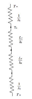
A very thin silicon chip is bonded to a 6-mm thick aluminum substrate by a 0.02-mm thick epoxy glue. Both surfaces of this chip-aluminum system are cooled by air at 250C, where the convective heat transfer coefficient of air flow is 100 W/(m2 K). If the heat dissipation per unit area from the chip is 104 W/m2 under steady state condition, draw the thermal circuit for the system and determine the operating temperature of the chip.
GIVEN
Silicon chip bonded to 6-mm thick aluminum substrate bye 0.02-mm thick epoxy glue
Air temperature(T∞)=250C
Convective heat transfer coefficient(h)=100 W/(m2 K)
Heat dissipation from chip(q/A)= 104 W/m2
FIND
Draw thermal circuit of system
Operating temperature of the chip.
ASSUMPTIONS
1-Dimensional Steady state conditions prevail
Negligible heat loss from the sides
Isothermal chip
Negliglble radiation
SKETCH
SOLUTION
From the figure
Total heat transferred to the surrounding is sum of heat transferred from upper surface and lower surface. Thus
COMMENT
The heat transfer occurs on both sides through the chip to the surrounding. As there are both conductive and convective resistances on the lower side heat flow rate on the lower side will be less than that on the upper side which has only convective resistance.
PROBLEM 2.8
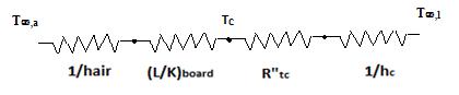
A thin, flat plate integrated circuit of 5 mm thickness is cooled on its upper surface by a dielectric liquid. The heat dissipation rate from the chip is 20,000 W/m2 and with the coolant flow at a free stream temperature of T∞,l =250C, the convective heat transfer coefficient between the chip surface and the liquid is 1000 W/(m2 K). On the lower surface, the chip is attached to a circuit board, where the thermal contact resistance between the chip and the board is 10-4 m2.K/W. The thermal conductivity of board material is 1.0 W/m. K, and its other surface ( away from the chip) is exposed to ambient air at T∞,a =200C where it is cooled by natural convection with the heat transfer coefficient of 30 W/(m2 K). (a) Determine the chip surface temperature under steady state condition for the described conditions. (b) If the maximum chip temperature is not to exceed 750C, determine maximum allowable heat flux that is generated by the chip. (c) A colleague suggests that in order to improve the cooling, you use a high conductivity bonding base at chip-board interface that would reduce the thermal contact resistance at the interface to 10-5 m2.K/W. Determine the consequent increase in the chip heat flux that can be sustained.
GIVEN
Heat dissipation rate (q )= 20,000 W/m2
Coolant free stream temp (T∞,l)= 250C
Ambientair temperature (T∞,a)= 200C
Heat transfer coefficient (h)= 1000 W/(m2 K)
Thermal contact resistance (R”tc) =10-4 m2.K/W
Maximumchip temperature=750C
FIND
(a) Chip surface temperature under steady state condition
(b) Maximum allowable heat flux generated by the chip
(c) Consequent increase in chip heat flux if high conductivity bonding is used.
ASSUMPTIONS
Steady state conditions prevail
The thermal conductivity of the wall (k) is constant
One dimensional conduction
Negligible radiation and thermal resistance between chip surface and the liquid.
SKETCH
The thermal circuit of problem is given by
SOLUTION
(a) A heat balance in the above problem gives
q = liquid q + air q
Substituting values from thermal circuits
(b)
for q from above equation, we get
55*26.01 W/m2
W/m2
4 W/m2
(c) Using the same equation as in (a), and changing only the value of thermal resistance, and using the value of Tc as 343 K, we get q=4.63*104 W/m2, which is a decrease in allowable heat dissipation of around 5126 W/m2
PROBLEM 2.9
In a large chemical factory, hot gases at 2273 Kare cooled by a liquid at 373 Kwith gas side and liquid side convection heat transfer coefficients of 50 and 1000 W/(m2 K), respectively. The wallthat separates the gas and liquid streams is composed of 2-cm thick slab of stainless steelon the liquid side. There is a contact resistance between the oxide layer and the steelof 0.05 m2.K/W. Determine the rate of heat loss from hot gases through the composite wall to the liquid.
GIVEN
Hot gases at Tg=2273 K cooled by liquid at Tf=373 K
Convection heat transfer coefficients on gas side hg=50 W/(m2 K) and hf=100 W/(m2 K)
Wall of stainless steel of thickness(L)= 2 cm = 0.02 m
Contact resistance (Rcr”)= 0.05 m2.K/W
FIND
Rate of heat loss from hot gases through composite wall to liquid.
ASSUMPTIONS
1 Dimensional steady state heat transfer

Thermal conductivity remain constant.
Radiation is negligible.
SKETCH
PROPERTIES AND CONSTANTS
From Appendix 2, Table 10, Thermal conductivity of stainless steel (k) = 14.4 W/(m2 K)
Total resistance for the heat flow through the pipe is given by
Heatflux for the above resistance for given temperature difference is given by
PROBLEM 2.10
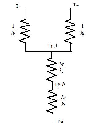
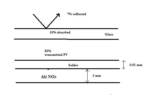
The conversion of solar energy into electric power by means of photovoltaic panels willbe an important part of the transition fromfossilfuels to sustainable energy resources. As described in detail in Principles of Sustainable Energy, a typicalPVpanel consists of a top layer of glass attached with a thin optically clear adhesive to a very thin layer of photoelectric material such as doped-silicon in which the incident solar irradiation is converted into electric energy. Experiments have shown that the solar to electric efficiency ƞ=0.55-0.001Tsilicon, where Tsilicon is the silicon temperature in K. In a typical installation where solar irradiation is G=700 W/m2, 7% is reflected from the top surface of the glass, 10% is absorbed by the glass, and 83% is transmitted to the photovoltaic active layer. A part of irradiation absorbed by photovoltaic materialis converted into heat and the remainder is converted into electric energy. The silicon layer is attached by a 0.01-mm thick layer of solder to a 3-mm thickaluminumnitride substrate as shown in the schemetic. Determine the electric power produced by this PVpanel, assuming the following properties for the pertinent materials: conductivity of the glass kg=1.4 W/(m K), conductivity of the adhesive ka=145 W/(m K), the emmisivity of the glass is 0.90, heat transfer coefficient fromthe top of the panel to the surrounding is 35 W/(m2K), and the surrounding air temperature is Tair=200C. The solar PVpanel is 5 m long and 1 mwide and is situated on the roof where the bottom is considered insulated. (Hint: Start by applying first law of thermodynamics to the photovoltaic-active layer and note that some of the irradiation willbe converted to electricity and some of it transmitted thermally).
GIVEN
Electric efficiency ƞ=0.55-0.001Tsilicon
Solar irradiation is G=700 W/m2
Thickness of solder(ts=0.01 mm
Al substrate thickness (tAl)=3 mm=0.003 m
Conductivityof the glass kg=1.4 W/(mK)
Conductivityof the adhesive ka=145 W/(mK)
Emissivityof the glass is 0.90
Heattransfer coefficientfromthe top of the panel to the surrounding(hc)= 35 W/(m2 K),
Surrounding air temperature is Tair=200C.
Solar PV panelarea= 5 m*1m
FIND
Electric power produced by the PV panel.
ASSUMPTIONS
1 Dimensional steady state heat transfer
Thermal conductivity remains constant.
SKETCH
PROPERTIES AND CONSTANTS
From Appendix 2, Table 10, Thermal conductivity of stainless steel (k) = 14.4 W/(m2 K)
SOLUTION
The energy which is not converted to electrical energy is transferred to the ambience through the adhesive and glass layer.
Also under steady state the heat transferred to the glass should be equal to total heat loss through glass to ambience.
Solving the above two equation in mathematical computational software (eg. Mathematica) we get
0.83*700*(1-0.55+0.001*306.6)*1*5 =2198 W=2.198 KW.
COMMENTS
The capacity of PV panel also depends on its cross sectional area. Thus more power can be generated if larger cross section of photovoltaic panels are used.