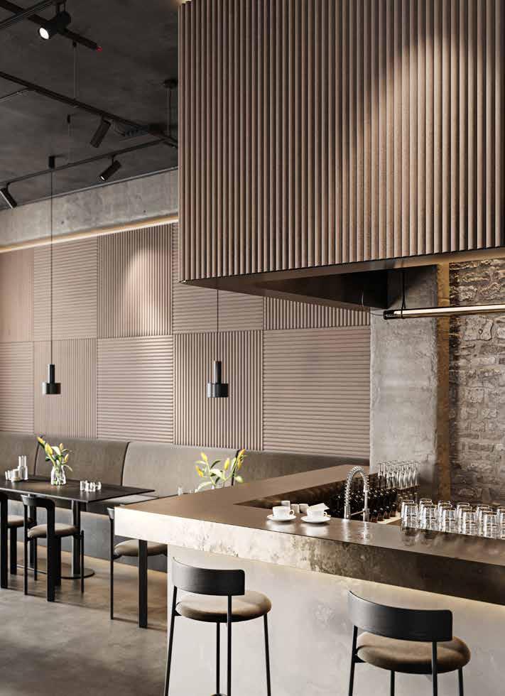
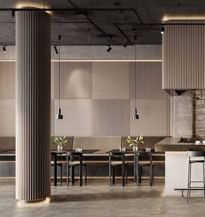
Room acoustics and room atmosphere play a decisive role for the well-being and productivity of people in their working and living spaces. The Wave wall module Infinity wall module was designed to meet the diverse requirements to optimally fulfil the diverse requirements of different rooms. This new wall system allows entire wall surfaces to be clad with acoustically effective wool felt elements. Whether in living rooms, offices or public facilities - this wall system ensures a pleasant sound atmosphere and minimises disturbing noises. The wall module Wave Infinity has the same positive characteristics of the Wave acoustic series with its
paravent, room and wall elements, but extends these with the option of completely covering large surfaces in order to acoustically dampen a room sustainably and efficiently. Thanks to its modular design, the system can be adapted to the wall surface and extended as required. The load-bearing structure consists of wooden frame modules that are attached vertically and horizontally to a wall surface. Thin metal tubes are pre-assembled on this wooden construction, onto which strips of wool felt are mounted. After installation, these form a continuous from the skirting board to the ceiling without any separations.
Design
Sonja Ophüls-Zilz
Contents
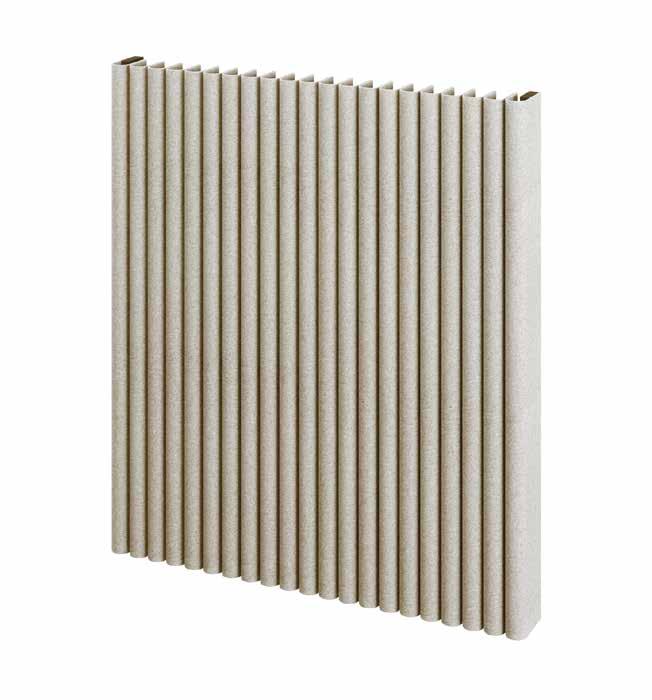
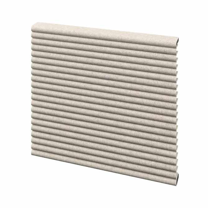
Felt strips in wave-look, arranged on a substructure
Material
Wool felt: 3mm thick, 100% pure new wool
Frame: MDF and FI/TA
Poles: Aluminium
Clamps / holder: galvanised steel
Availability
Made to order, delivery time by arrangement
Material properties
Wool felt is air-permeable, dimensionally stable, heat and cold insulating, flame-retardant, sound-absorbing and improves the the room air. The natural wool grease protects the surface from from soiling and the penetration of liquids is largely prevented.
Care
See HEY-SIGN care brochure
Lightfastness
3-5 depending on the colour shade
Environment
The wool felt used consists of a renewable raw material, 100% pure new wool, contains no formaldehydes, is free from volatile organic compounds, does not contain any chemical irritants and is free from hazardous substances in accordance with the REACH regulation. Due to its quality, our wool felt has been awarded the wool seal of approval from ‘The Woolmark Company’. The metal elements are fully recyclable.
Special features
As a renewable raw material, wool is subject to natural fluctuations in its properties. Despite all the care taken in the manufacturing process, it is possible that there may be vegetal inclusions or variations in the surface, which may show up as roughness, melanges or unevenness in a few places. These do not represent a defect, but emphasise the naturalness of the wool felt material. Dyed wool felts from different production batches differ despite having the same colour and thickness, as the wools used take on the colours differently. If the same colour is required, a sufficient quantity of wool felt from one production batch must therefore be used. Wool felts of the same colour but different thicknesses always differ slightly, which should be taken into account when combining different material thicknesses.
Optional chemical finishes
+ Flame protection
Finished wool felt is classified as B-s2, d0 in accordance with DIN EN 13501-1 classified. The finish anchors itself crystalline in the structure of the structure of the wool felt. In the case of heavily frequented surfaces the finish will diminish over time through use. Order quantities and prices on request.
+ Protection against soiling from water and oil Information and prices on request
+ Moth protection Information and prices on request
Wave Infinity straight vertical
Product
Wave Infinity wall module - straight vertical
Material
Wool felt: 3mm thick, 100% pure new wool
Frame: MDF and FI/TA
Poles: straight made of aluminium or Alu/KS
Tube clamps and tube holders: galvanised steel
With the new Wave Infinity extension, vertical surfaces can now also be seamlessly covered. This function makes it possible to integrate straight structures harmoniously into the room design and at the same time effectively improve the room acoustics. The precise finish of the panelling helps to improve the room acoustics by reducing disturbing noises. This versatility makes the system particularly flexible and an elegant solution for interiors where aesthetic and acoustic requirements are equally important.
Scope of delivery, sizes and weights
External angle (W × D): 9.9 cm × 5.5 cm
2 pieces per segment incl. pre-assembled tube clamps
Customised lengths according to the height of the surface:
Individual dimensions 40 -120 cm
Connector set of 2, incl. screws for vertical connection of several external angles.
Rods: Cut straight to size
Wool felt strips: Number and length are calculated according to the surface size and prefabricated for covering Colours: min. 80 cm wall width of one colour
Depth of entire system: 9 cm
Weight of entire system: 8 kg/m²
Calculation principle (see diagram on the following page)
The actual wall width is divided into equal segment widths: max. 80 cm / min. 40 cm.
The segment width is divided by the visible width of the ‘wave’. The number must be odd. The two wider strips of wool felt with only one row of holes cover the respective outer angles. The remaining strips have two rows of holes and form the ‘waves’ in between. The calculation is always according to the size of the wall surface. To customise the system to an individual size, an additional one-off installation set-up fee will be charged.
Connector pair/set
For a vertical combination of 3 modules, 2 sets of connectors are required. Results in 8 rows × 2 sets = 16 sets (32 connectors).
Wool felt strips
View width: approx. 4 cm
Quantity: Frame width 78.6 cm : 4 cm = 19.65 pieces results in 19 pieces × 8 module rows = 152 strips
Length of the strips: approx. 260 cm
Assembly (see diagram on the following page)
First, the prefabricated wooden frames are laid down according to the height of the modules to be combined (e.g. on the floor, assembly table, assembly trestles). The wooden frames are provided with holes on the inside of the sides. The frames are connected there with the metal connectors and screws. The combined wooden frames are positioned horizontally in accordance with the desired floor clearance (plinth height / prevention of soiling due to floor cleaning) and a possible top / side shadow gap (when panelling a complete wall) ( Fig. 1).
The screws of the pipe clamps on the combined frames must then be opened on one side - in our case on the left - and turned to the side (Fig. 2).
The felt strips are then slid over the hole cut-outs on the loosened metal rods. Start on the outside with an 18 cm wide strip with only one row of holes, followed by the narrower strips on the inside and finally the second wider strip on the other outside (Fig. 3).
After the strips / felt corrugations have been pushed on, the pipe clamps are turned back into the locking position and the screws are tightened. Finally, the outside strips / felt strips can be glued to the frame. To do this, peel off the protective film on the outside of the frame, place the loose felt strip flush against the rear edge of the frame and then press it down over the entire surface (Fig. 4).
TIP: Pressing can be intensified with a pressure roller.
For the final assembly of the Wave Infinity, the assembled elements are placed back against the wall as previously aligned.
Then slide the strips / felt corrugations slightly apart at the positions of the slotted holes and fix the frames to the wall through the slotted holes using screws (not included) and the metal washers supplied. The rows of panels can now be moved sideways and aligned thanks to the central position of the fixings. This avoids wider gaps between the rows of panels. After alignment, the screws are tightened. Finally, the strips / felt corrugations need to be painted by hand to evenly align the shape of the ‘waves’ and the gaps between them.
Safety instructions
- Before drilling, make sure that there are no electricity, water or gas pipes in the area.
- Use screws and/or wall plugs that are suitable for the wall. No screws and wall plugs are included.
- The manufacturer accepts no liability for any damage caused by improper use or installation. Subsequent changes to the acoustic element mean that the person who makes these changes is deemed to be the manufacturer for the purposes of product liability.
L i e f e r u m f a n g :
H o l z r a h m e n , Ve r b i n d e r, v e r z i n k t e U n t e r l e g s c h e i b e n , S t r e i f e n a u s
Wo l l f i l z ( We l l e n ) 1 6 u n d 1 8 c m , e n t s p r e c h e n d d e r b e s t e l l t e n A n z a h l
d e r M o d u l e
N i c h t i n d e r L i e f e r u n g e n t h a l t e n s i n d b e n ö t i g t e S c h r a u b e n u n d
D ü b e l , d a d i e B e f e s t i g u n g d u r c h d i e m o n t i e r e n d e F a c h f i r m a a u f d i e
B e s c h a f f e n h e i t u n d Tr a g f ä h i g k e i t d e s U n t e r g r u n d e s a b g e s t i m m t
w e r d e n m u s s .
M o n t a g e :
Z u e r s t w e r d e n d i e v o r g e f e r t i g t e n H o l z r a h m e n e n t s p r e c h e n d d e r i n
d e r H ö h e z u k o m b i n i e r e n d e n M o d u l e h i n g e l e g t ( z B a u f B o d e n ,
M o n t a g e t i s c h , M o n t a g e b ö c k e ) D i e H o l z r a h m e n s i n d s e i t l i c h i n n e n
m i t B o h r u n g e n v e r s e h e n D o r t w e r d e n d i e R a h m e n m i t d e n
m e t a l l e n e n Ve r b i n d e r n u n d d e n S c h r a u b e n v e r b u n d e n .
A b s c h l i e ß e n d k ö n n e n d i e a u ß e n p l a t z i e r t e n S t r e i f e n / F i l z w e l l e n m i t
d e m R a h m e n v e r k l e b t w e r d e n . D a z u w i r d d i e S c h u t z f o l i e a u f
AlleMaßeincm
All dimensions in cm
d e r R a h m e n a u ß e n s e i t e a b g e z o g e n , d e r l o s e F i l z s t r e i f e n b ü n d i g a n
d e r h i n t e r e n K a n t e d e s R a h m e n s a u f g e s e t z t u n d d a n n f l ä c h i g
a n g e d r ü c k t ( A b b 4 )
TIPP: Mit einer Andruckrolle kann das Anpressen intensiviert werden
Z u r E n d m o n t a g e d e r We l l e I n f i n i t y w e r d e n d i e m o n t i e r t e n E l e m e n t e
w i e v o r h e r b e r e i t s a u s g e r i c h t e t , w i e d e r a n d i e Wa n d g e s t e l l t
S c h i e b e n S i e d a n n d i e S t r e i f e n / F i l z w e l l e n b e i d e n P o s i t i o n e n d e r
L a n g l ö c h e r n l e i c h t a u s e i n a n d e r u n d f i x i e r e n S i e d i e R a h m e n m i t
S c h r a u b e n ( n i c h t i m L i e f e r u m f a n g d a b e i ) u n d d e n m i t g e l i e f e r t e n
m e t a l l e n e n U n t e r l e g s c h e i b e n d u r c h d i e L a n g l ö c h e r a u f d e r Wa n d
D u r c h d i e m i t t i g e P o s i t i o n d e r F i x i e r u n g k ö n n e n d i e E l e m e n t r e i h e n
D i e m i t e i n a n d e r k o m b i n i e r t e n H o l z r a h m e n w e r d e n g e m ä ß d e s
n u n s e i t l i c h v e r s c h o b e n u n d a u s g e r i c h t e t w e r d e n D a d u r c h w e r d e n
A u s r i c h t e n w e r d e n d i e S c h r a u b e n f e s t g e z o g e n
Right: The front shows a homogeneous pattern of waves without vertical separations. On the left and right, each module frame is covered with felt strips.
b r e i t e r e F u g e n z w i s c h e n d e n E l e m e n t r e i h e n v e r m i e d e n N a c h d e m
Z u m S c h l u s s m ü s s e n d i e S t r e i f e n / F i l z w e l l e n v o n H a n d n a c h g e -
Beispiel:Wandgröße(B×H):630×260
Example: Wall size (W × H): 630 × 260
g l e i c h m ä ß i g a u s z u r i c h t e n
S i ch e r h e i t s h i n w e i s e :
s t r i c h e n w e r d e n , u m d i e F o r m d e r „ We l l e n “ u n d d i e Z w i s c h e n f u g e n
- S t e l l e n S i e v o r d e m B o h r e n s i c h e r, d a s s s i c h i n d i e s e m B e r e i c h k e i n e S t r o m, Wa s s e r- o d e r G a s l e i t u n g e n b e f i n d e n
- B e n u t z e n S i e S c h r a u b e n u n d / o d e r D ü b e l , d i e f ü r d i e Wa n d
g e e i g n e t s i n d E s s i n d k e i n e S c h r a u b e n u n d D ü b e l b e i g e f ü g t
- F ü r e n t s t e h e n d e S c h ä d e n d u r c h u n s a c h g e m ä ß e n E i n s a t z o d e r
M o n t a g e ü b e r n i m m t d e r H e r s t e l l e r k e i n e H a f t u n g N a c h t r ä g l i c h e
Ä n d e r u n g e n a m A k u s t i k e l e m e n t f ü h r e n d a z u , d a s s d e r j e n i g e
a l s H e r s t e l l e r i m S i n n e d e r P r o d u k t h a f t u n g g i l t , d e r d i e s e
With the new extension to the Wave Infinity system, straight surfaces can now also be customised. This customisation not only offers an aesthetic design option for horizontal structures, but also helps to improve room acoustics. Disturbing noises are significantly reduced, resulting in a more pleasant sound environment. With this flexibility, the system offers an ideal solution for interiors where both visual sophistication and acoustic performance are paramount.
Scope of delivery, sizes and weights
Wooden frame module (W×H×D): max. 80 cm x 120 cm x 5.5 cm
Weight: 5 kg/m²
Wooden frame incl. pre-assembled metal tubes, module connectors and pre-assembled wool felt strips for covering. The number and dimensions are calculated according to the calculated according to the area size.
Total system depth: 9 cm
Total system weight: 7.5 kg/m²
Special features
From a second module row onwards, a further colour can be colour can be selected.
Calculation principle (see diagram on the following page)
A module width of 80.6 cm is fitted with 21 strips of wool felt. wool felt. Of these, 19 are 16 cm wide and 2 are 18 cm wide. wide. The wider strips cover the two horizontal frame timbers. frame timbers. The calculation is always made according to the size of the wall surface. To customise the system to an individual individual size, an additional one-off set-up fee will be charged.
Connector pair/set
For a horizontal combination of 3 modules, 2 sets of connectors of connectors are required.
Wool felt strips
View width: approx. 4 cm
Quantity: frame width in cm divided by 4 cm = number per module row x number of module rows
Length of the strips: Height of the surface minus height of the plinth and minus the distance to the ceiling
Assembly (see diagram on the page after next)
Lay the prefabricated wooden frames flat according to the width to be combined (e.g. on the floor, assembly table, assembly trestles). The wooden frames are provided with holes on the inside of the long sides. Connect the frames at these points using the metal connectors and screws ( Fig. 1 ).
Position the combined wooden frames on the wall, taking into account the floor clearance (plinth height) to avoid soiling and the distance to neighbouring walls / fixtures. Level the frames and mark the centre of the fixing holes through the holes in the fixing strips. After you have placed the wooden frames down again, drill the fixing holes in the wall and insert the wall plugs (Fig. 2).
Open the pipe clamps on one side and turn the upper shells to the side ( Fig. 3 ).
Slide the felt strips over the hole cut-outs on the detached pipes. Start at the bottom with an 18 cm wide strip with only one row of holes. Slide the first row of holes of an inner strip onto the rods. Then place a spacer in each case and slide on the second row of holes. Proceed in the same way with all the inner strips and finally with the second wider strip at the top ( Fig. 4 ).
Insert the lower ends of the pipes into the open pipe clamps and turn the upper shells of the pipe clamps back into the closed position. Tighten the screws. Secure the pipe with a locking screw. Start with the left-hand rod ( Fig. 5 ).
Now glue the outer strips / felt shafts to the frame. Remove the protective film on the outside of the frame, place the loose felt strip flush against the rear edge of the frame and press it down over the entire surface ( Fig. 6 ).
TIP: Pressing can be intensified with a pressure roller. For the final assembly of the Infinity wave, the assembled module row is repositioned on the wall as previously aligned. Slide the strips / felt waves slightly apart to expose the fixing holes and screw the frames through the holes onto the wall.
When combining several rows of modules on top of each other, proceed in the same way with the following rows (Fig. 7 ).
Once all module rows have been installed, the strips / felt waves must be repainted by hand to evenly align the shape of the ‘waves’ and the intermediate joints.
Safety instructions
- Before drilling, make sure that there are no electricity, water or gas pipes in the area.
- Use screws and/or wall plugs that are suitable for the wall. No screws and wall plugs are included.
- The manufacturer accepts no liability for any damage caused by improper use or installation. Subsequent changes to the acoustic element mean that the person who makes these changes is deemed to be the manufacturer for the purposes of product liability.
Dimensions
Wandmodul WelleInfinity - horizontal Maße
Alle Maß ein cm
Example of use All dimensions in cm View from above Frame structure from the front
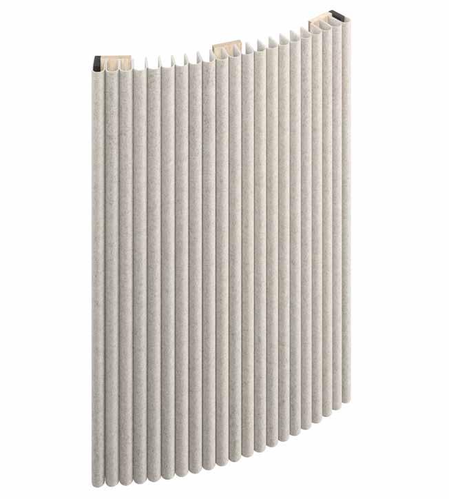
With the new extension to Wave Infinity curved surfaces can now also be clad seamlessly. This function makes it possible to integrate curved and straight structures harmoniously into the room design and at the same time effectively improve the room acoustics. The precise processing of the panelling helps to improve the room acoustics by reducing disturbing noises. This versatility makes the system particularly flexible and an elegant solution for interiors where aesthetic and acoustic requirements are equally important.
Scope of delivery, sizes and weights
External angle (W × D): 9.9 cm× 5.5 cm
2 pieces per segment incl. pre-assembled tube clamps
Centre support (W × D): 8 cm× 1.6 cm
1 piece per 80 cm segment width incl. pre-assembled tube brackets
Customised lengths according to the height of the surface:
Individual dimensions 40 -120 cm
Connector set of 2, incl. screws for vertical connection of several external angles.
Rods: bent and cut to size
Wool felt strips: Number and length are calculated according to the to the surface size and prefabricated for covering
Cover width of a ‘wave’ approx. 3.8 cm
Colours: min. 80 cm wall width of one colour
Depth of entire system: 9 cm
Weight of entire system: 8 kg/m²
Calculation principle (see diagram on the following page)
The actual wall width is divided into equal segment widths: max. 80 cm / min. 40 cm
The segment width is divided by the visible width of the ‘wave’. The number must be odd. The two wider strips of wool felt with only one row of holes cover the respective outer angles. The remaining strips have two rows of holes and form the ‘waves’ in between.
The calculation is always based on the size of the wall surface. An additional one-off set-up fee is charged for customising the system to an individual size.
Connector pair/set
For a vertical combination of 3 modules, 2 sets of connectors are required. Results in 8 rows × 2 sets = 16 sets (32 connectors)
Wool felt strips
View width: approx. 4 cm
Quantity: Frame width 78.6 cm : 4 cm = 19.65 pieces results in 19 pieces × 8 module rows = 152 strips
Length of the strips: approx. 260 cm
Assembly (see diagram on the page after next)
Firstly, the L-profiles are laid on the floor, for example, according to the height of the modules to be combined, and screwed together with the metal connectors. The L-profiles are provided with holes on the inside of the sides for the supplied connectors and screws (Fig. 1).
The first vertically combined L-profile is now mounted exactly vertically on the relevant wall with a circumferential minimum clearance of 6 cm at the bottom, top and sides (Fig. 2).
The pipe clamps point in the direction of the other segments. The next opposite L-profile is then mounted to complete the first module. The centre rails are then also fitted exactly in the middle. The wall fixings should be placed in the same position everywhere within the slotted holes so that no ‘play’ is wasted (Fig. 3).
The tubes are best pre-curved to the appropriate shape by pressing them against the rounded wall surface (Fig. 4).
Then slide the wool felt strips of this module with the respective top hole cut-out of the strips onto the first pipe.The 18 cm wide version with only one hole is slid on first and last. The free end points towards the room (Fig. 5).
Now open the screws of the pipe clamps and turn the upper shells of the clamps to the side (Fig. 6).
Then hook this pipe with the felt strips into the top pipe clamps of the L-profiles and the centre bar holder (Fig. 7).
Then turn the loosened clamp shells back into the closed position and tighten the screws. Use the metal screws supplied to fix this tube in front of the clamp in the L-profile (Fig. 8).
This ensures that all the felt strips hang securely in the upper tube so that the remaining tubes can now be pushed through the respective hole cut-outs in the wool felt strips one after the other (Fig. 9).
Hang the placed tubes one after the other, from top to bottom, in the same way and fix them in the clamps as described above. Finally, glue the outer strips to the side L-profiles.
To do this, remove the protective film from the respective L-profile, place the loose felt strip flush with the rear edge of the moulding from top to bottom and then press down over the entire surface (Fig. 10).
TIP: Pressing can be intensified with a pressure roller. Proceed with the installation of all further module rows next to this first row as described (Fig. 11).
It should be noted that the subsequent modules are first installed at a distance of 6 cm from the previous module so that they can be pushed up to the previous module after the outer strips have been glued on. The screws should therefore be positioned in the slotted holes in such a way that there is enough ‘play’ for the modules to be pushed towards each other (Fig. 3). The wall fastenings should also not be tightened until after the modules have been pushed in. In this way, the modules are mounted row by row.
Finally, the strips / felt waves must be repainted by hand to evenly align the shape of the ‘waves’ and the intermediate joints.
Safety instructions
- Before drilling, make sure that there are no electricity, water or gas pipes in the area.
- Use screws and/or wall plugs that are suitable for the wall. No screws and wall plugs are included.
- The manufacturer accepts no liability for any damage caused by improper use or installation. Subsequent changes to the acoustic element mean that the person who makes these changes is deemed to be the manufacturer for the purposes of product liability.
Right: The front shows a homogeneous pattern of waves without vertical separations. On the left and right, each module frame is covered with felt strips.
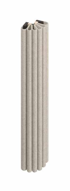
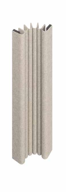
Wave Infinity has now been extended to include the option of cladding internal and external corners. This customisation makes it possible to effectively design even hard-to-reach areas while improving the acoustic quality of the room. This customisation makes the system particularly versatile and offers an ideal solution for rooms where both design requirements and acoustic functionality are important.
Wooden frame module (W×H×D): max. 80 cm x 120 cm x 5.5 cm
Weight: 5 kg/m²
Wooden frame incl. pre-assembled metal tubes, module connectors and pre-assembled wool felt strips for covering.
The number and dimensions are calculated according to the calculated according to the area size.
Total system depth: 9 cm
Total system weight: 7.5 kg/m²
Special features
An additional colour can be selected from a second row of modules.
Calculation principle (see diagram on the following page)
Wooden frame module (W×H×D)
Outer corner: approx. 20.9 x 20.9 x 5.5 cm
Inside corner: approx. 14.6/14.6 x 5.5 cm
Maximum module height: approx. 120 cm
Weight: 5 kg/m²
The number and dimensions are calculated according to the wall height.
Connector pair/set
For a vertical combination of 3 modules, 2 sets of connectors are required.
Wool felt strips
View width: approx. 4 cm
Quantity: 5
Length of the strips: Height of the surface minus the height of the plinth and minus the distance to the ceiling
Assembly (see diagram on the page after next)
Lay the prefabricated modules flat according to the height of the modules to be combined (e.g. on the floor, assembly table, assembly trestles). The left-hand MDF strip is supplied disassembled for easier installation of the wool felt strips. The wooden frames are provided with holes on the inside of the long sides. Connect the frames to these holes using the metal connectors and screws ( Fig. 1 ).
Position the combined wooden frames on the wall, paying attention to the floor clearance (plinth height to avoid soiling), the distance to substructures and the upper distance to neighbouring walls or fixtures. Align the frames horizontally. Mark the fixing holes on the wall through the holes in the mouldings. After positioning the wooden frames again, drill the fixing holes in the wall and insert the wall plugs ( Fig. 2 ).
Open the pipe clamps on one side of the left-hand frame timber and turn the upper shells to the side ( Fig. 3 ).
Slide the felt strips over the hole cut-outs onto the first bent tube. Start at the top left with a wide outer strip that only has one row of holes. Proceed in the same way with all the inner strips and finish on the right with the second wider strip (Fig. 4).
Hang this first tube with the attached felt strips in the upper tube holders. Turn the upper shell of the left-hand pipe clamp back into the locked position and tighten the screws. Secure the pipe with a locking screw. Now secure the right-hand end of the pipe by screwing the loose upper shell onto the pipe clamp and additionally securing the pipe with the locking screw. Then push all the pipes through the hole cut-outs in the strips and fix the tubes one after the other from top to bottom as described above. Now screw the loose side MDF strip to the substructure (Fig. 5).
Now glue the outer strips / felt strips to the frame. To do this, peel off the protective film on the outside of the frame, place the loose felt strip flush against the rear edge of the frame and press it down over the entire surface (Fig. 6).
TIP: Pressing can be intensified with a pressure roller. For final assembly, position the assembled module corner in the corner of the room as prepared. Slide the outer strips / felt strips slightly to the side at the fixing holes in the frame and screw the corner module to the wall ( Fig. 7 ).
After installation, the strips / felt strips must be repainted by hand to evenly align the shape of the ‘waves’ and the intermediate joints.
Safety instructions
- Before drilling, make sure that there are no electricity, water or gas pipes in the area.
- Use screws and/or wall plugs that are suitable for the wall. No screws and wall plugs are included.
- The manufacturer accepts no liability for any damage caused by improper use or installation. Subsequent changes to the acoustic element mean that the person who makes these changes is deemed to be the manufacturer for the purposes of product liability.
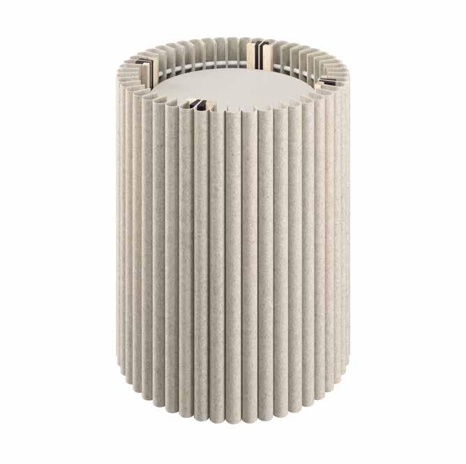
Welle Infinity has been expanded to include a new function that enables targeted panelling of room columns. This extension not only improves the visual integration of pillars into the room design, but also ensures efficient acoustic optimisation. The special panelling is designed to acoustically treat complex, round surfaces such as pillars and reduce disturbing noises. This results in more pleasant room acoustics. This flexibility makes the system particularly versatile and ideal for interiors where both aesthetic design and acoustic requirements play a key role.
Scope of delivery, sizes and weights
L-shaped mouldings (W × D): 9.9 cm × 5.5 cm
incl. pre-assembled tube holder. Partial lengths are adapted to the individual height of the room column. Individual length min. 40 - 120 cm
Connector: Set of 2, incl. screws for vertical connection with several L-shaped mouldings.
Blind base for on-site lamination: height 6 cm
Bars: are pre-bent to individual radius and cut to size
Wool felt strips: Number and length are calculated according to the surface size and prefabricated for covering Overlooking width of a ‘wave’: approx. 3.8 cm
Colours: min. 80 cm overlay width of one colour
Depth of entire system: 9 cm
Weight of entire system: approx. 8 kg/m²
Calculation principle (see diagram on the following page)
Diameter of the room column min. 40 cm / max. 80 cm. The panelling is divided into 4 equal segments. The segment outer surface is divided by the visible width of the ‘wave’. The number must be odd. The two wider strips of wool felt with only one row of holes cover the respective outer angles. The remaining strips have two rows of holes and form the ‘waves’ in between. The calculation is always based on the desired size. An additional one-off set-up fee is charged for customising the system to an individual size.
Assembly (see diagram on the page after next)
First place the vertical frame slats according to the labelling left/right and top/bottom according to the number to be combined vertically (e.g. on the floor, assembly table, assembly trestles). The frame rails are provided with holes on the inside of the long sides. Connect the frame rails there using the metal connectors and screws ( Fig. 1 ).
The frame rails are fitted with the pipe clamps. They are slightly open on the left-hand side and the upper shells are removed on the right-hand side. These are only fitted when the felt-covered bars are inserted. Slide the felt strips over the hole cut-outs onto the prebent tubes. Start on the left-hand side with an 18 cm wide strip with only one row of holes. Then slide on the narrower inner strips and finally the second wider strip on the outer right-hand side (Fig. 2).
Once you have slid on all the strips / felt corrugations, insert the ends of the pipes into the pipe clamps. Turn the pipe clamps back into the closed position and fix the screws ( Fig. 3 ).
Screw an additional locking screw through the hole provided in the frame. Start with the pipe at the top left. Then insert the pipes into the pipe holders on the other side. Start at the top right. Screw on the loose upper shells and insert a locking screw (Fig. 4).
Now glue the outer strips / felt strips to the frame. To do this, peel off the protective film on the outside of the frame, place the loose felt strip flush against the rear edge of the frame and press it down over the entire surface ( Fig. 5 ).
TIP: Pressing can be intensified with a pressure roller. After completing the first column segment, assemble all other segments in the same way. Then couple two segments together. For this purpose, the outer felt slats are provided with cut-outs and the left-hand frame timbers with holes. Secure the two segments to the wooden frame members using clamps. Now screw the frames together using the wood screws supplied ( Fig. 6 ).
Set up the two half-segments and position them on the building column to be clad. Align the half-segments to each other and fix them to the frame timbers with clamps. Screw the two halves together ( Fig. 7 ).
Then align the structure using the levelling feet. Adjust the spacers via the cut-outs in the outer felt slats so that the column cladding is pressed evenly against the building column (Fig. 8).
Finally, adjust the blind base around the circumference and screw it to the frame timbers ( Fig. 9 ).
After installation, you will need to smooth the strips / felt waves by hand to evenly align the shape of the ‘waves’ and the intermediate joints.
Safety instructions
- Before drilling, make sure that there are no electricity, water or gas pipes in the area.
- Use screws and/or wall plugs that are suitable for the wall. No screws and wall plugs are included.
- The manufacturer accepts no liability for any damage caused by improper use or installation. Subsequent changes to the acoustic element mean that the person who makes these changes is deemed to be the manufacturer for the purposes of product liability.