E. N. Van Beek PORTFOLIO

03 09 17
03 09 17
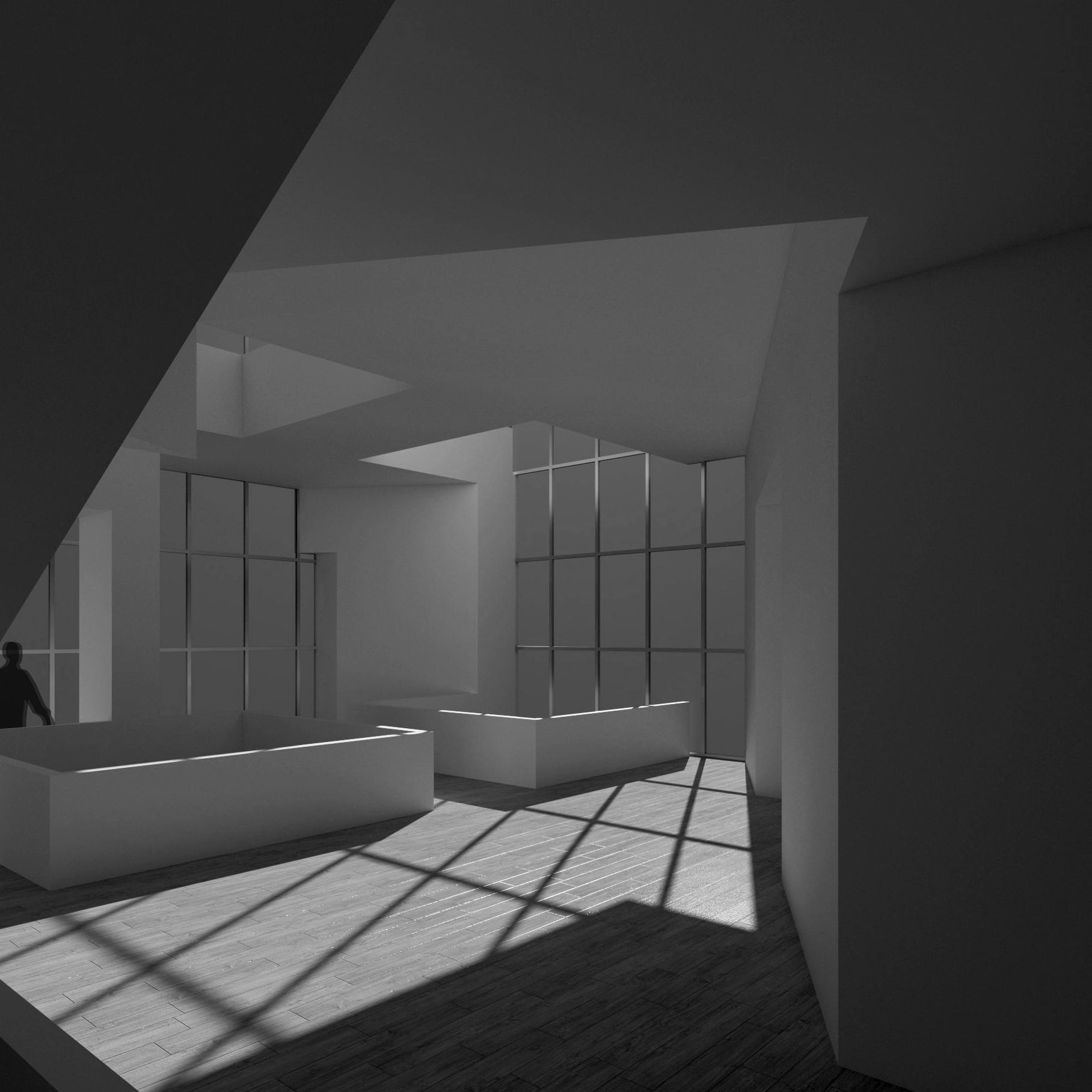
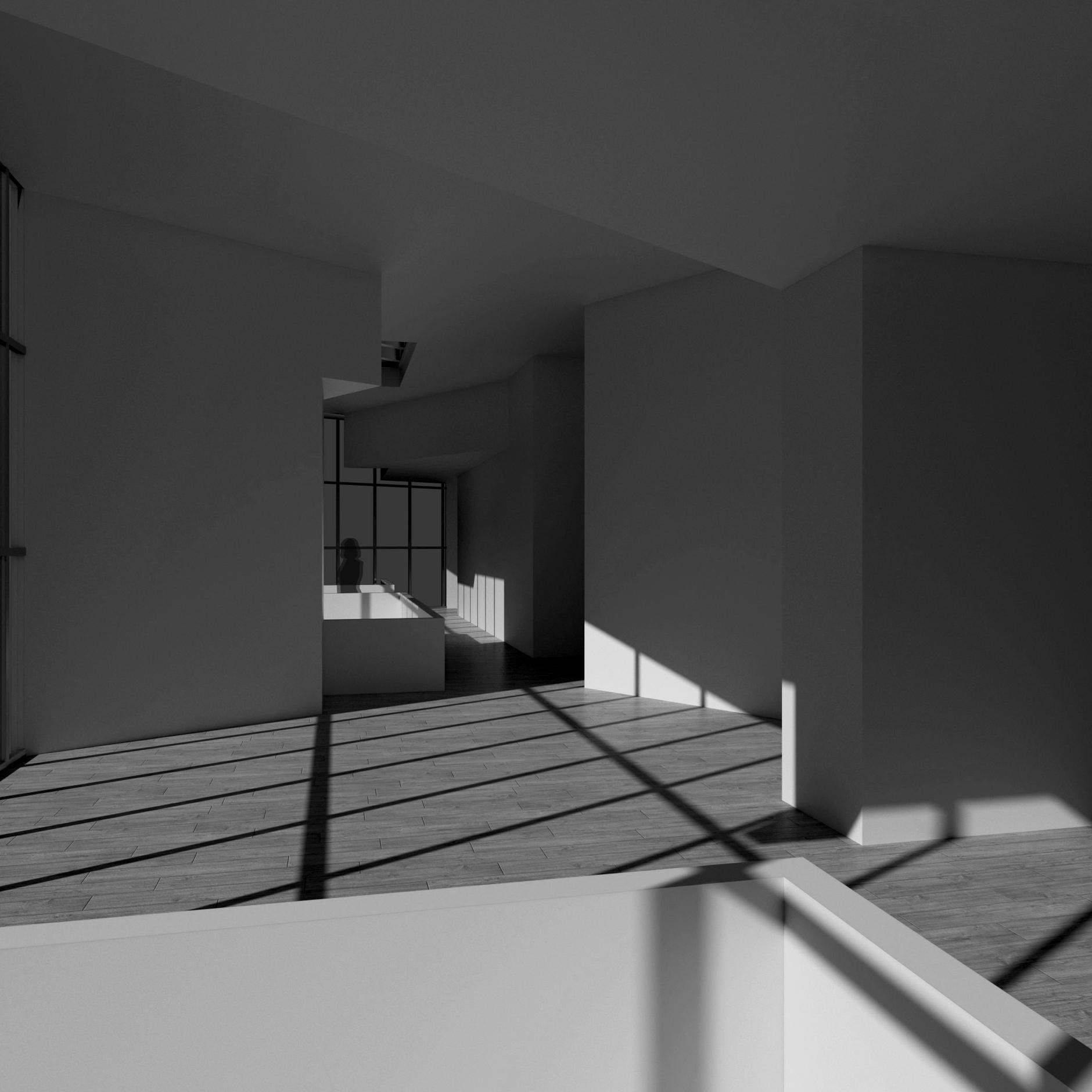
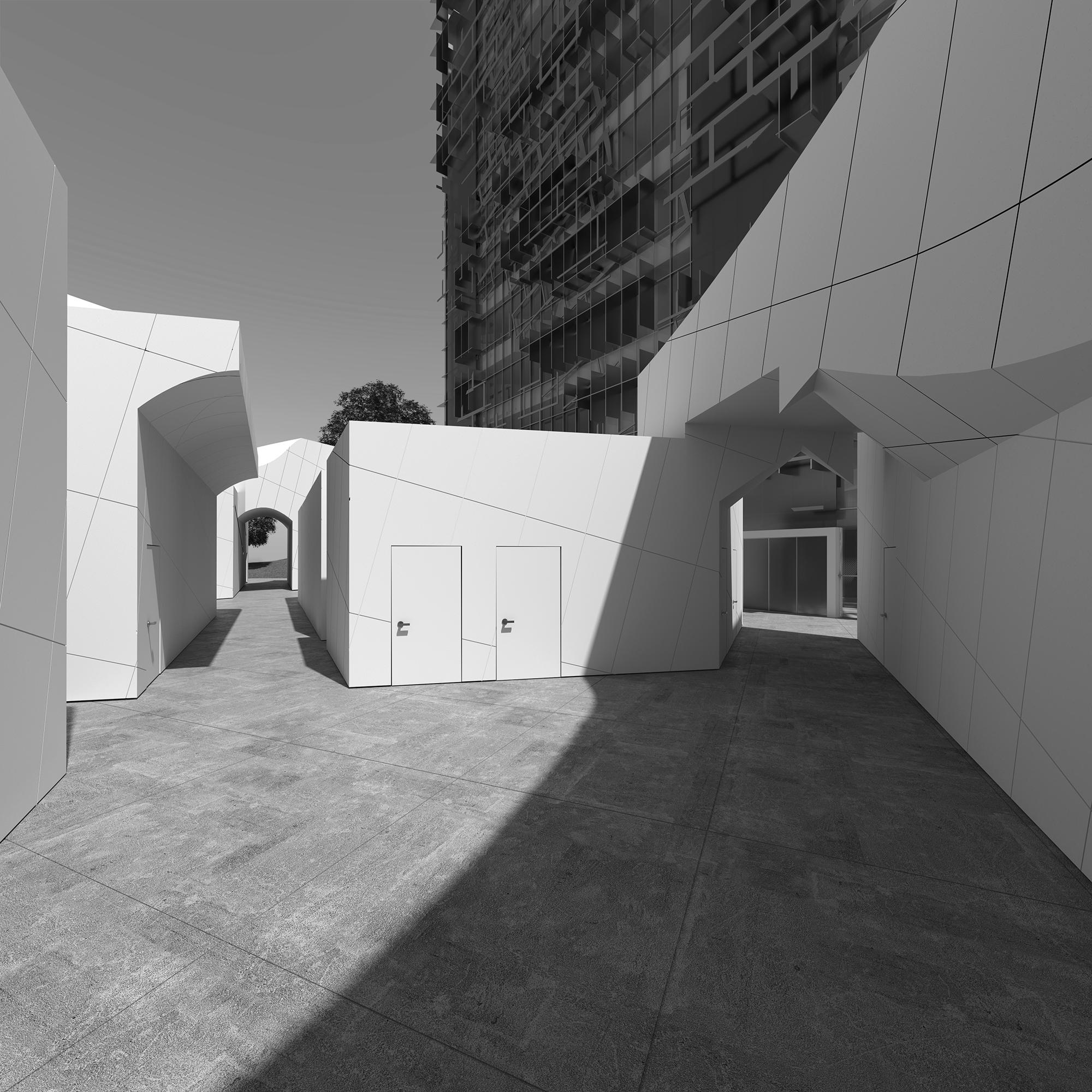
Museum of Contemporary Japanese Art

CLA Adaptive Reuse School of Architecture
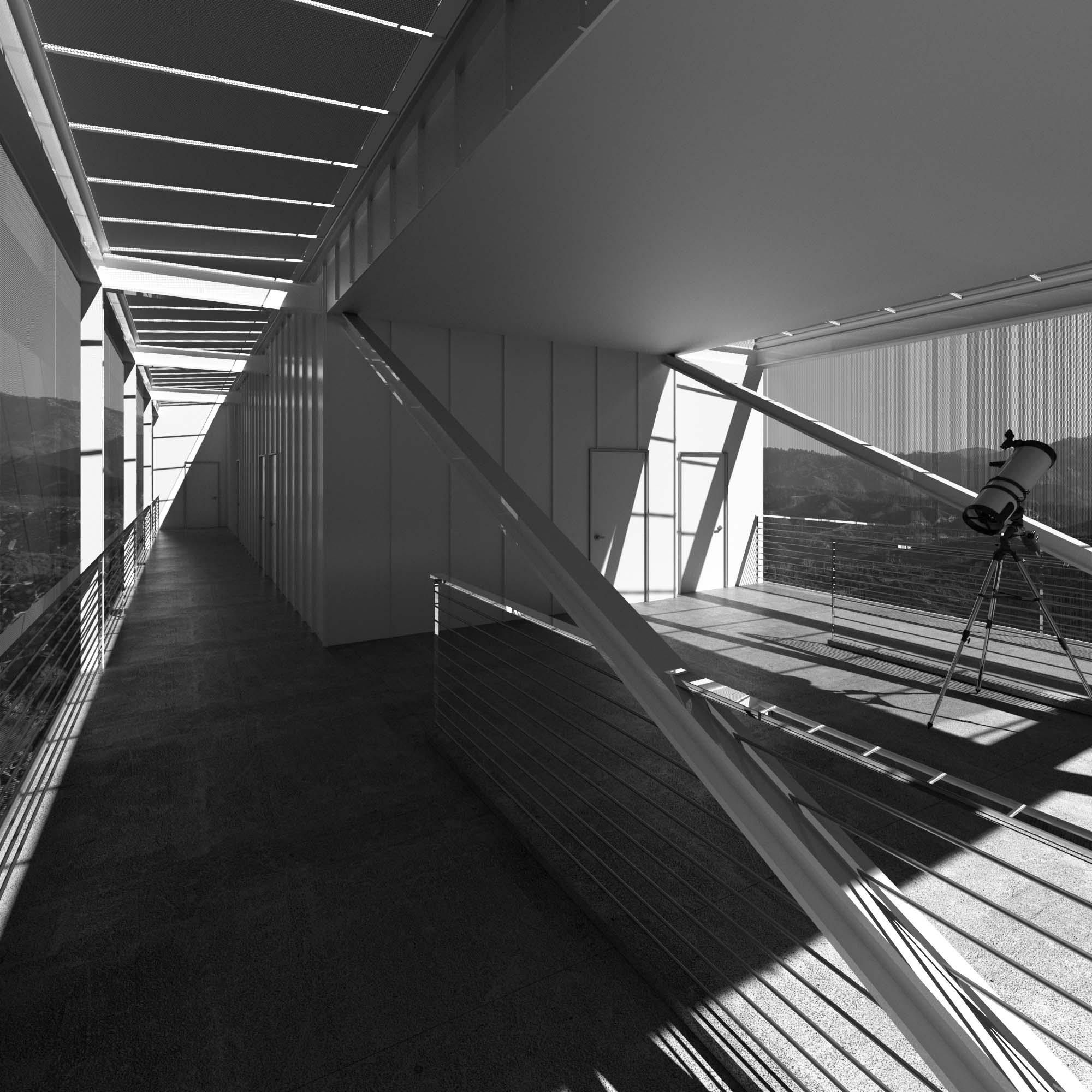
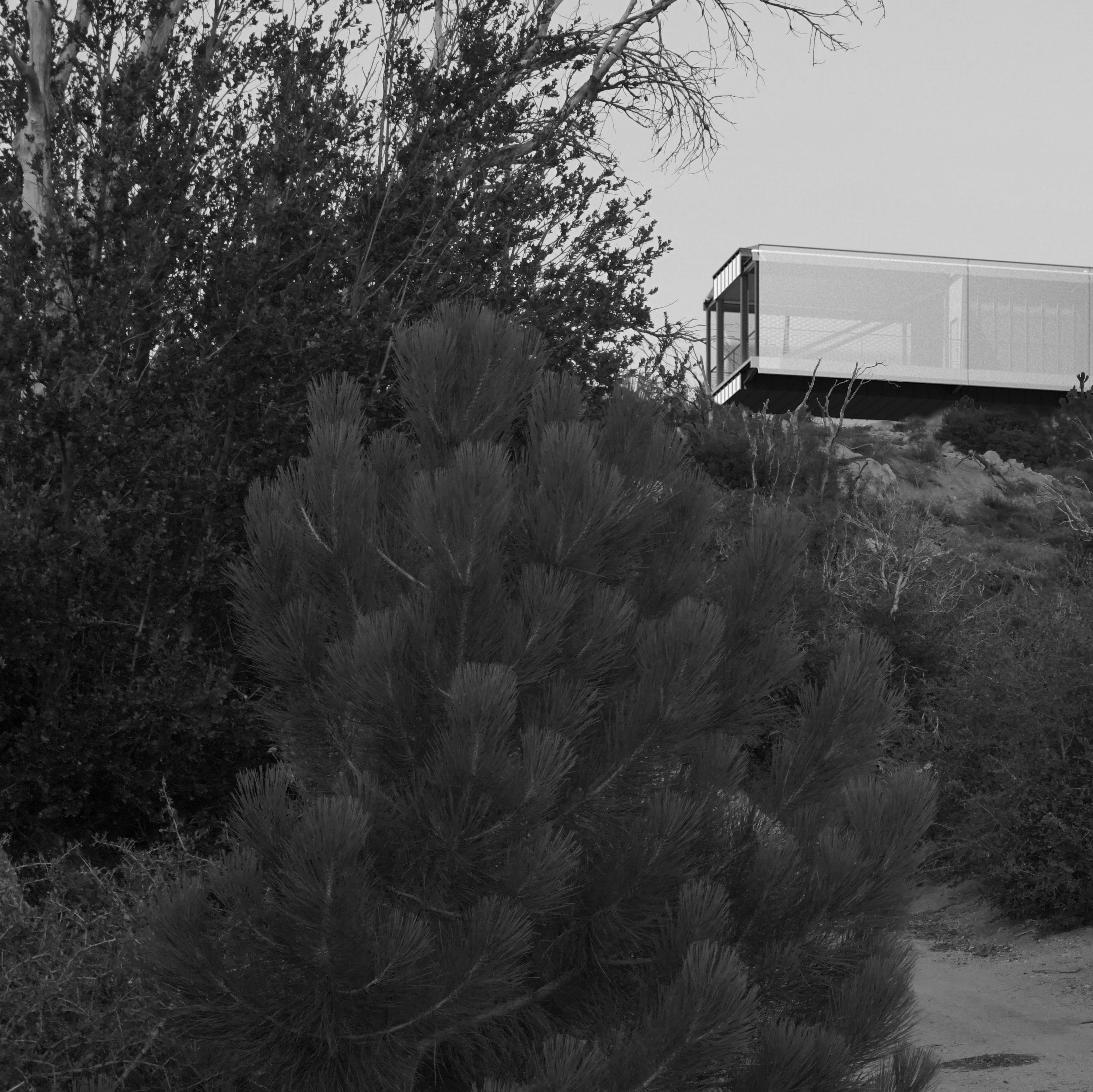
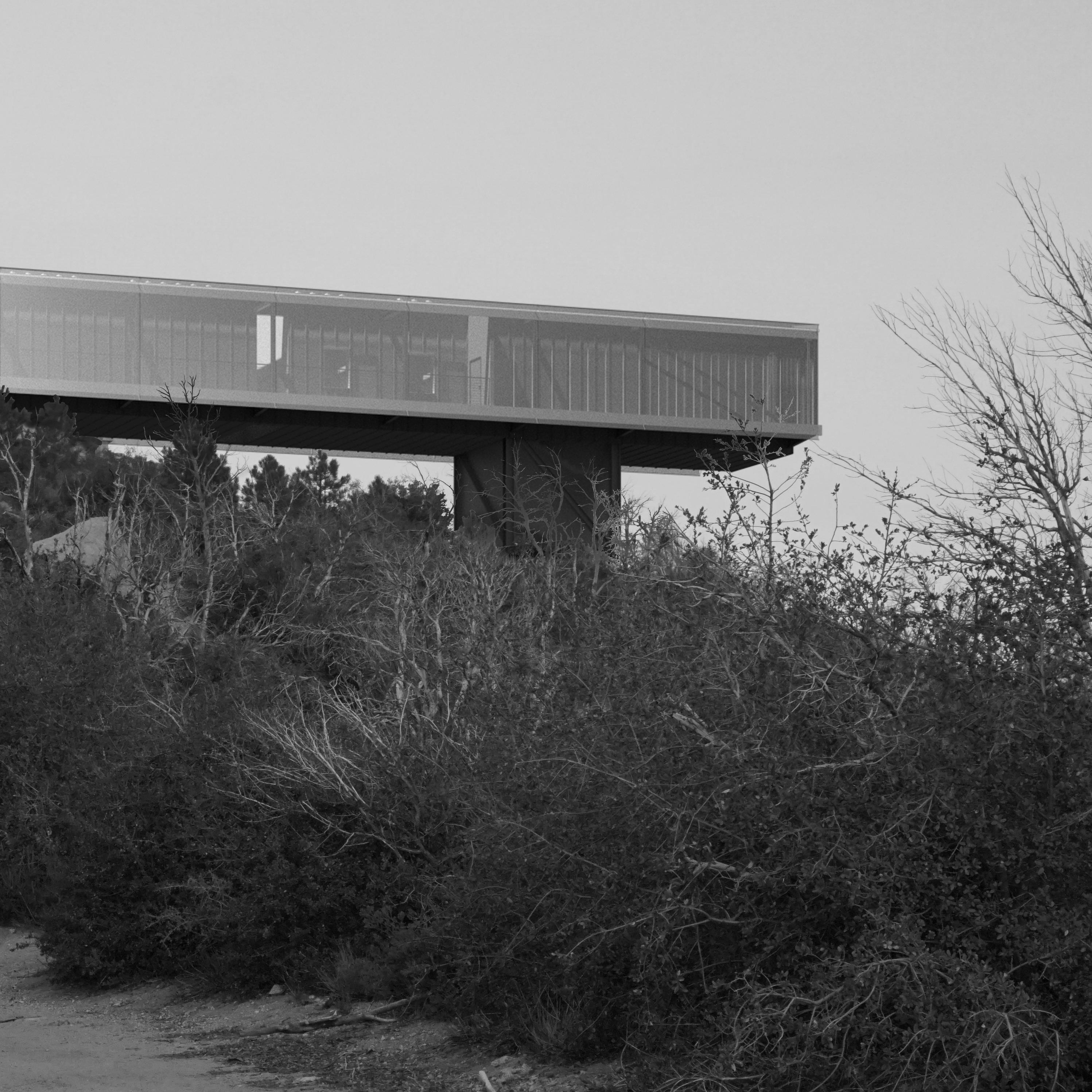
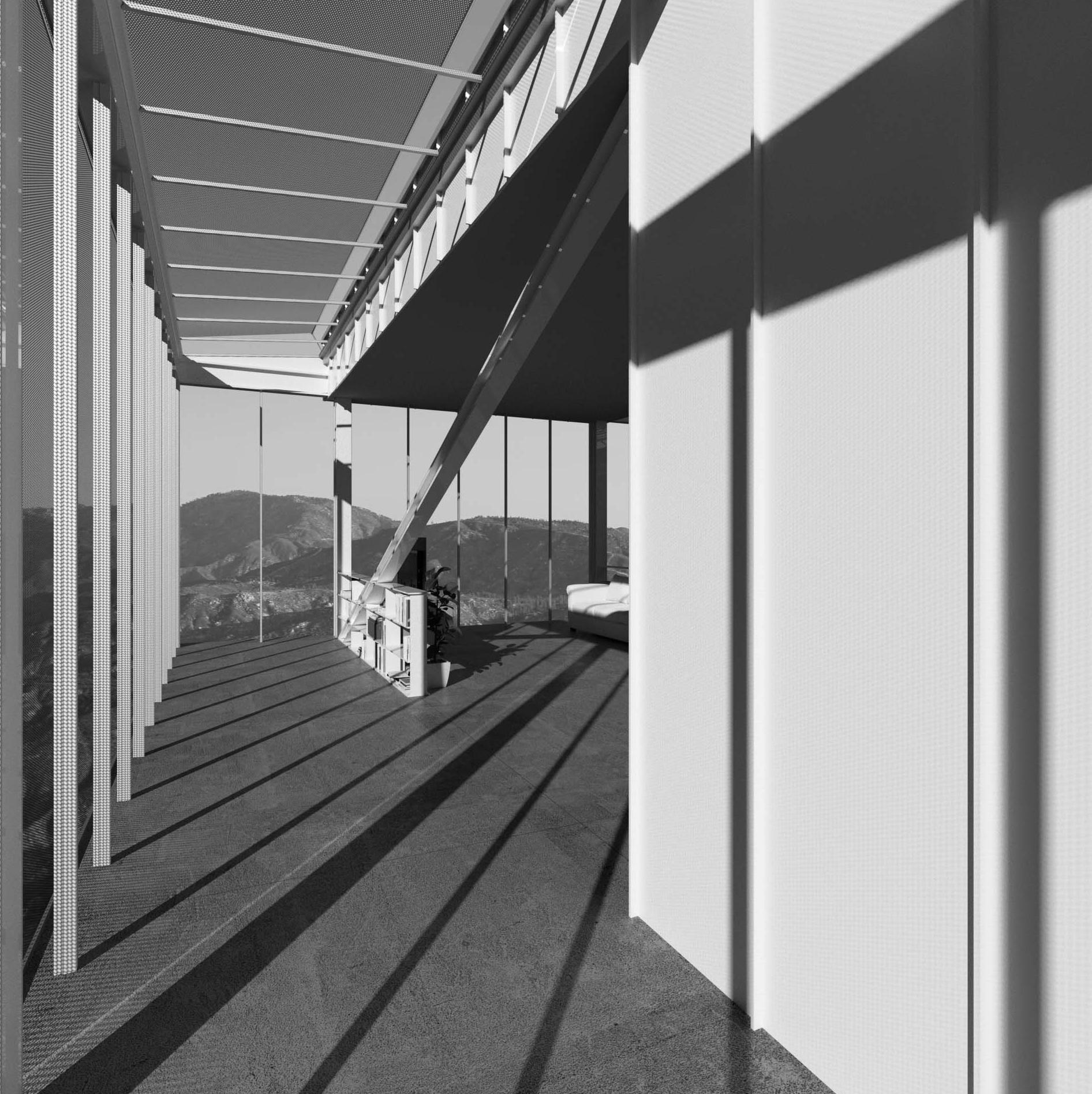
Vetter Mountain Scientist’s Retreat
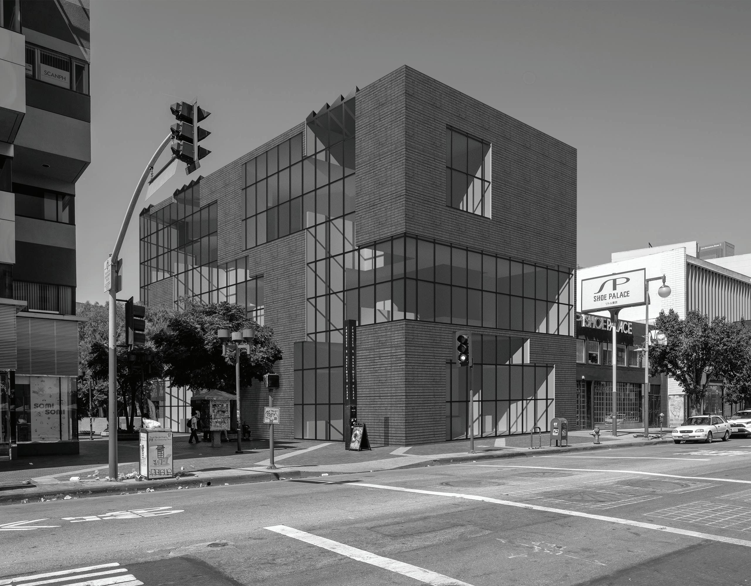
The space making strategy employed in this project was based on a series of boolean subtractions from a greater mass. The boolean operations were modulated depending on the size of the subtraction being made. The masses were scaled, rotated, and elongated in order to create a variety of spaces. The figure-ground diagrams produced by this perforated mass were then studied and arranged to accomodate museum programming. Horizontal subtractions created the major galleries and delineated open from enclosed spaces. Vertical subtractions acted as the major vertical circulation elements and created voids that connected several floors sectionally.
UP DN UP
1 - Lobby
1 - Lobby 2 - Cafe 3 - Kitchen 4 - Secondary Entry 5 - Restrooms
Ground Floor Plan 50’ 25’ 10’ 5’ 1’
2 - Cafe 3 - Kitchen 4 - Secondary Entry 5 - Restrooms
DN 1 - Lobby 2 - Cafe 3 - Kitchen 4 - Secondary Entry 5 - Restrooms
Ground Floor Plan 1/8” = 1’
50’ 25’ 10’ 5’ 1’
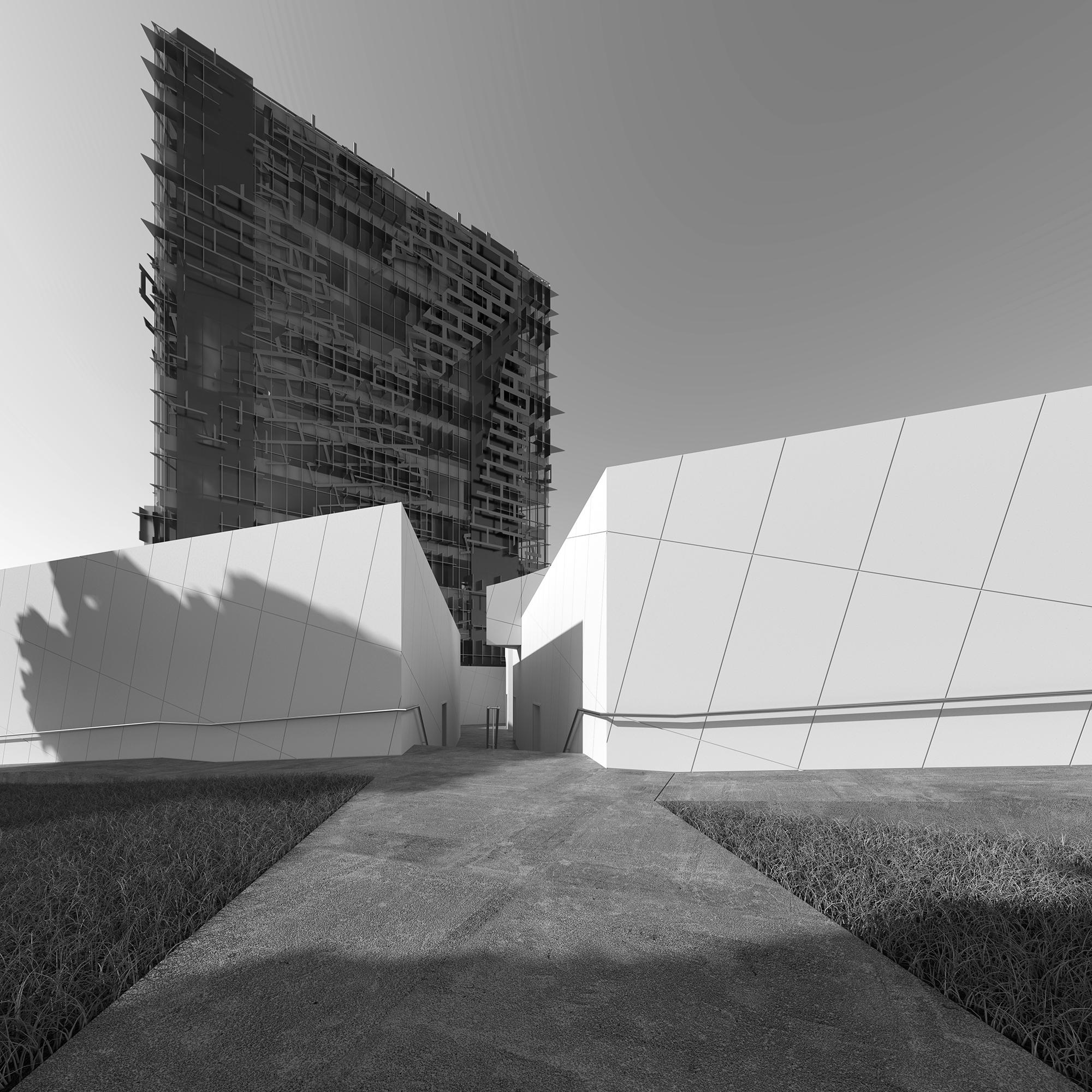
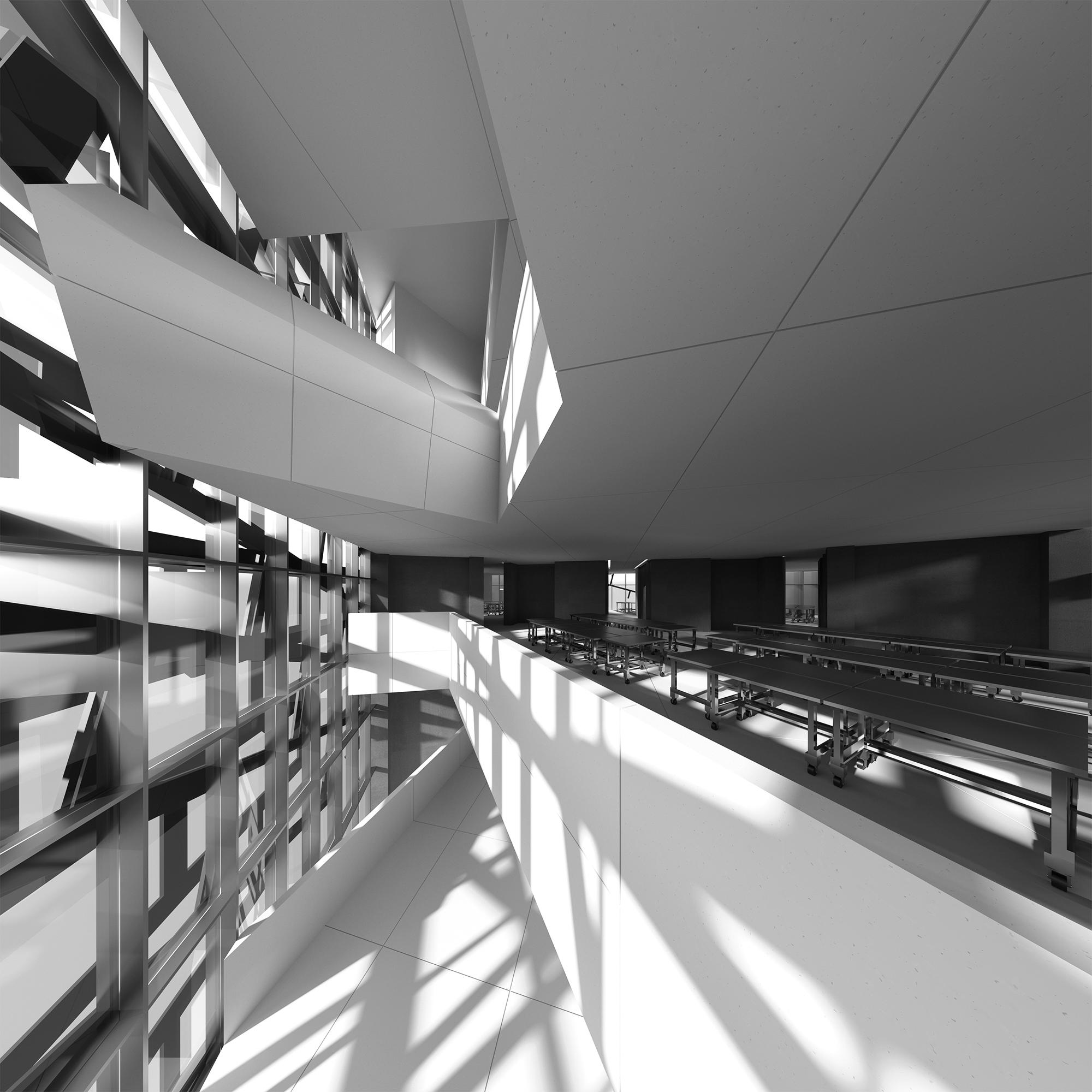
The first stage of the generative process was to develop a sculptural armature from a field of differing orthogonal, angular, and curved lines. The datums of this sculptural relief were then identified and used to form the major walkways within the plinth. These walkways generate spaces of spatial ambiguity at their intersections and provide moments with long site lines with an ingrained sense of visual rhythm. A similar datum-based generative process was then applied to the tower. The field that generated the original armature was cropped and the axes were again identified and used as paths that carved masses, creating space for program between them. Datums were established, split, trimmed, offset, dropped and picked back up again. These spacemaking operations occurred in plan, section, and elevation and aided in cohering the differing typologies of plinth and tower. This proved to be one of the emergent struggles of the studio problem. In order to connect the typologies, more subtle references are formed based on the subtractions in plan and section and the planar expression in the facade.
E. L. + 166’
E. L. + 151’
E. L. + 136’
E. L. + 121’
E. L. + 106’
E. L. + 091’
E. L. + 076’
E. L. + 061’
E. L. + 046’
E. L. + 031’
E. L. + 016’
E. L. + 181’ Section A
1/16” = 1’
Third Floor Plan
100' 50' 0' 25' 10'
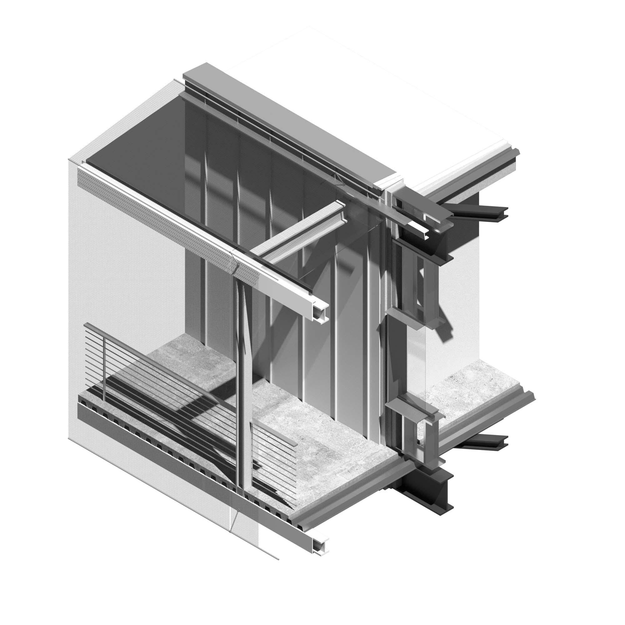
Roof Membrane Vapor Barrier 1- 1 2 " Rigid Insulation 1 2 " OSB 2x" Studs Wide Flange Steel Fiberglass Insulation 3 4 Gypsum Board
2" Standing Seam Panels Vapor Barrier 1- 1 2 " Rigid Insulation 1 2 " OSB 2x10" Light Gauge Steel Wide Flange Steel Fiberglass Insulation 3 4 Gypsum Board
Poured Concrete 3" Corrugated Steel Decking Wide Flange Steel Fiberglass Insulation 1 2 " OSB 1- 1 2 " Rigid Insulation Vapor Barrier 2" Standing Seam Panels