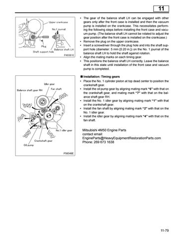
11 • The gear of the balance shaft LH can be engaged with other gears only after the front case is installed and then the vacuum pump is installed on the crankcase. This necessitates performing the following steps before installing the front case and vacuum pump. (The balance shaft LH cannot be rotated to adjust the gear position after the front case is installed on the crankcase.) • Remove the plug on the upper crankcase. • Insert a screwdriver through the plug hole and into the shaft support hole (diameter: 5 mm {0.20 in.}) on the No. 1 journal of the balance shaft LH to hold the shaft against rotation. • Align the mating marks on each timing gear. • This positions the balance shaft LH correctly. Leave the balance shaft in this state until installation of the front case and vacuum pump is completed. Installation: Timing gears • Place the No. 1 cylinder piston at top dead center to position the crankshaft gear. • Install the oil pump gear by aligning mating mark “6” with that on the crankshaft gear, and mating mark “7” with that on the balance shaft gear RH. • Install the No. 1 idler gear by aligning mating mark “1” with that on the crankshaft gear. • Install the fan shaft by aligning mating mark “2” with that on the No. 1 idler gear. • Install the idler gear by aligning mating mark “4” with that on the fan shaft.
Mitsubishi 4M50 Engine Parts contact email: EngineParts@HeavyEquipmentRestorationParts.com Phone: 269 673 1638
11-79