IVECO 8061 Engine Workshop Manual FIAT aifo 8061

Page 1

gensets

genset engines power units

8061 Engine Workshop Manual

IVECO 8061

FIAT 8061

aifo 8061

WORKSHOP MANUAL

IVECO FIAT aifo

The data contained in this publication may not have been updated following modifications carried out by the manufacturer, at any time, foe technical or commercial reasons and also to conform to the requirements of the law in the various countries.

This publication supplies features and data together with the suitable methods for repair operations to be carried out on each single components of the gensets and genset engines. Following the supplied instructions and using the inherent specific fixtures, a correct repair procedure will be obtained in due time, protecting the operators from all possible accidents. Before starting any repair, be sure that all accident prevention devices are available and efficient.

Therefore check and wear what indicated by the safety provision protective glasses, helmet, gloves, safety shoes.

Before use, check all work, lifting and transport equipment.

- - � � �•··--··-·····

TABLE OF CONTENTS

GENERAL 8061 ENGINE SPECIFICATIONS page 1

SPECIFICATIONS ON ASSEMBLY CLEARANCES page 3

TIGHTENING TORQUES SPECIFICATIONS page 9

SPECIAL TOOLS page 10

FAULT DIAGNOSIS - TROUBLE SHOOTING page 11

DISMANTLING OF THE GENSET page 22

ENGINE BENCH DISASSEMBLY page 22

CYLINDER BLOCK page 25

CAMSHAFT page 28

BUSHINGS page 29.

TAPPETS LIFTERS page 30

CRANKSHAFT page 31

FLYWHEEL page 36

CONNECTING ROD and PISTON ASSEMBLY page 36..

TIMING GEARS page 42

CYLINDER HEAD page 44

INTAKE VALVES EXHAUST VALVES page 45

VALVE GUIDES page 45

PUSH RODS page 48

LUBRICATION - ENGINE OIL PUMP page 50

COOLING - ENGINE WATER PUMP page 52

MOUNTING OF THE INJECTION PUMP AND TIMING page 53

OVERHAUL OF THE ELECTRIC MACHINE page 55

REASSEMBLING THE ENGINE page 55

ASSEMBLING OF THE ALTERNATOR WITH THE ENGINE page 57

8061 ENGINE
(
/ 8001 GENERAL Engine p. 1 TIMING Valve Timing - Intake opens: before T.D.C .............................................. 12° closes: afters B.D.C............................................... 31 ° - Exhaust opens : before B.D.C ..............................................50° closes: afters .D.C .................................................. 16 ° Clearance betwe8n valves and rockers for timing checks ...................................................0,45 mm Operating clearance between valves and rockers, cold engine: intake and exhaust. .........................................0,30 mm FUEL SYSTEM In line injection pump type Bosch VE6 Fixed injection pump delivery start advance...8° ± 0,5° Fuel injectors setting..................................250 + 3 bar Firing order ....................................... 1 -5 -3 -6 -2 -4 LUBRICATION Minimun oil pressure: - at full throttle 2 kg/cm2 - when idling...............................................0,7 kg/cm2 STARTING By starter motor ** ELECTRIC SYSTEM FOR • GENSET ENGINE 8061SI 06 A.550 • GENSET ENGINE 8061SI 06 A.580 - GENSET G.E. 8061SI 06 A.955 •• GENSET ENGINE 8061SI 07 A.550 - GENSET ENGINE 8061SI 07 A.580 - GENSET G.E. 8061SI 07 A.955 - Voltage..............................................................12 V - Self - regulated alternator......................... 14 V, 45 A - Starting motor power 3 KW - Battery (optional )...................................... 1X180 Ah ** ELECTRIC SYSTEM FOR : GENSET 8061SI 06 A.956 • GENSET 8061SI 07 A.956 - Voltage..............................................................24 V - Self - regulated alternator 28 V, 30 A - Starting motor power. ..................................... .4 KW - Battery (optional)......................................2X120 Ah

**

Valve Timing - Intake opens: before T.D.C .............................................. 12° closes: afters B.D.C............................................... 31 ° - Exhaust opens : before B.D.C..............................................50° closes : afters D.C.................................................. 16° Clearance between valves and rockers for timing checks...................................................0,45 mm Operating clearance between valves and rockers, cold engine: intake and exhaust. .........................................0,30 mm FUEL SYSTEM In line injection pump type Bosch VE6 Fixed injection pump delivery start advance 3° ± 0,5° Fuel injectors setting..................................250 + 3 bar Firing order .' 1 - 5 -3 - 6 -2 -4
Minimun oil pressure: - at full throttle................................................2 kg/cm2 - when idling...............................................0,7 kg/cm2
By starter motor
ELECTRIC SYSTEM FOR • GENSET ENGINE 8061SRI 26 A.550 • GENSET ENGINE 8061SRI 26 A.580 • GENSET G.E. 8061SRI 26 A.955 - GENSET ENGINE 8061SRI 27 A.550 • GENSET ENGINE 8061SRI 27 A.580 • GENSET G.E. 8061SRI 27 A.955 - Voltage.............................................................. 12 V - Self - regulated alternator......................... 14 V, 45 A - Starting motor power.......................................3 KW - Battery (optional )...................................... 1X180 Ah
8001 GENERAL Engine p. 2 TIMING
LUBRICATION
STARTING
**
ELECTRIC SYSTEM
- GENSET 8061SRI 26 A.956 " GENSET 8061SRI 27 A.956 - Voltage..............................................................24 V - Self - regulated alternator 28 V, 30 A - Starting motor power...................................... .4 KW - Battery (optional )......................................2X120 Ah l )
FOR
,, ) ,_ / 8001
CYLINDER BLOCK AND CRANK MECHANISM COMPONENTS 01 1J} 02 & l4 � > 03 X x 02 9,,62 l4 ! lT X q 03 y(;J _,,.,._ rfil{ 2 mm Bores for cylinder liners 0 I I06,85 + I06,90 Cylinder liners: outside diameter 02 I06,94 + I06,97 length L 198,00 + 198,50 Cylinder liners-crankcase bores 0,04 + 0,12 Outside diameter 02 0,2 Cylinder liners inside diameter � 03 I04,000 + I04,024 protrusion X Pistons: measurement height X 12 outside diameter 01 I03,870 + I03,852 housing for gudgeon pin 02 38,000 + 38,006 Piston-cylinder liner 0, I30+0, 172 Piston diameter 01 0,4 - 0,8 Piston protrusion X 0,64 + 0,97 Gudgeon pin 03 37,984 + 37,990 Gudgeon pin - pin housing 0,010+0,022 XI* 3,20 + 3,23 Piston ring grooves X2 2,55 + 2,57 X3 4,03 +4,05 *measured on IO I mm diameter Engine p. 3
DATA ON ASSEMBLY CLEARANCES
8001 Engine p. 4 tt· - --=------------------------------------------\:{:_. mm SI* 3,095 + 3,075 {S I Piston rings S2 2,490 + 20478 I I I ! S3 3,990 + 3,975 measured on IOI mm diameter I 0, I05 + 0, 155 9e Piston ring - grooves 2 0,060 + 0,092 3 0,040 +O,Q75 [4 � > Piston rings 0,4 -0,8 XI Piston ring end gap in 5{ cylinder liner: X2 XI 0,30 + 0,55 X3 X2 0,60 + 0,85 X3 0,30 + 0,60(1 )) 01 Small end bush • housing 01 41,846 + 41,884 Big end bearing ( t02 housing 02 67,407 + 67,422 • 04 Small end bush diameter .Yi 0 03 outside 04 41,979 + 42,017 inside � 03 38,004 + 38,014 ( s- Big end bearing shell s 1,805 + 1,815 (S=thickness) & Small end bush - housing 0,095 + 0, 171 9e Gudgeon pin - bush 0,014 + 0,03 I 1 '.:4 � Big end bearing shells 0,254 - 0,508 X � Measurement dimension X 125 Maximum out-of-parallel 4J error on connecting rod axesO,Q7l J ·----- ./
/ I 8001 01 02 " SI S 2 J-Jm0J 9,,e [4 ['1'\,:::o XI ,,,--..... v-----)-... X2 9,,e [4 I 2 -1,1-Jn Sr [ J \ Engine p. 5 mm Main journals 01 79,791 + 79,810 Crankpins 02 63,725 + 63,744 Main bearing shells SI 2,169 + 2,178 (S=thickness) Big end bearing shells S 2. I,805 + I,8 I5 (S=thickness) Main bearing housings 03 84,200 + 84,230 Bearing shells - main 0,034 + 0, IO I journals Bearing shells - crankpins 0,033 + 0,087 Main bearing shells 0,254 - 0,508 Big end bearing shells Main journal, thrust bearing XI 32,0 + 32, I Main bearing housing, thrust bearing X2 25,0 IO+ 25,060 Thrust washer halves X3 3,378 + 3,429 Crankshaft end float 0,082 + 0,334 Thrust washer halves 0,254 - 0,508 - 0,762 - 1,016 I 0.10 Alignment {2 ±0,25 Ovality 1-2 0,008 Taper 1-2 0,012
8001 CYLINDER HEAD. VALVE GEAR 01 02 03 se 01 02 a c9 Valve guide housings in the cylinder head 0 I Valve guide 02 03 Valve guides and seatings in the head Valve guides Valves: � Valve stem and its guide Housing in head for valve seat 04 a 04 a 01 01 Outside diameter ofvalve seat; angle of valve seat in cylinder head c:fil Recessing of valves Between valve seat and head 02 a 02 a X mm 13.950 + 13.983 8.023 + 8.043 13.993+ 14.016 0.0I0 + 0.066 + 0.2 7.985 + 8.000 60° 30' ± 7' 7.985 + 8.00 45° 30' ± 7' 0.023 + 0.058 39.000 + 39.025 60° ± 5' 39.136 + 39.161 45° ± 5' 0.7 + I 0.111 + 0.161 Engine p. 6 (
8001 Engine p. 7 •·. _.) mm Valve spring height Free height H 44.6 a D H !IF 1 1i 2 Under aload of 270 ± 14 N HI 34 528 ± 26 N H2 23.8 -) Injector protrusion X -·. 0.7 + 1.5 ) i I X � Camshaft bec).ring housing in crankcase 01 55.280 + 55.305 02 54.780 + 54.805 03 54.280+ 54.305 0 I 2 3 04 53.780 + 53.805 02 Camshaft bearing journals 1 05 51.470 + 51.500 06 50.970 + 51.000 __I ' __J 3 07 50.470 + 50.500 01 0 3 08 49.970 + 50.000 Outside diameter of at·; camshaft bushes front 01 55.375 + 55.430 54.875 + 54.930 0 3 front intermediate 02 54.375 + 54.430 rear intermediate 03 rear 04 53.875 + 53.930 Inside diameter 01 of bushes 02 front 01 51.580 + 51.630 03 f ront intermediate 02 51.080 + 5I.I30 rear intermediate 03 50.580 + 50.630 rear 04 50.080 + 50. I30 c9 Bushes and housings in crankcase O.G7+0.15 91? Bushes and bearing 0.08 + 0.16 journals \. )_./
8001 �H o· 02 9E Effective cam lift q}J H � H Tappet cup housing in crankcase 0 I Outside diameter of tappet cup Between tappets and housings Tappets Rocker shaft Rockers 02 03 01 02 Between rockers and shaft "MOTOMETER" VALUES TD.C. pressure • bar Min. permissible TD.C. pressure • bar Engine motoring over speed rpm mm 5.97 6.25 15.000 + 15.0 I8 14.740 + 14.780 14.950 + 14.970 0.030 + 0.068 0.1 - 0.2 - 0.3 17.982 + 18.000 I8.0 I6 + 18.034 0.016 + 0.052 '.', 19 ::::: 260
Engine p. 8 /( l I t _.I
(*) Starter-driven engine with oil temperature at 40° - 50° C and injection pump at shut-off.

8001

TIGHTENING TORQUE

DESCRI PTIOI\J

Cylinder head capscrev, stage I: pretightening stage 2: pret1ghten1ng stage 3: angie

Caoscrew. main beanng caps prt1ghten1ng angie

Capscrew, connecting md caos pr·etightenrng angle

Fiywheel fixrng screv,.-

Nut for· injector fixing stud

Oil sump fixing screw

Oil sump drain plug

Heater seat plug

pretightening angle

pretightening endtightening

Capscrew, rh and lh rear bracket

Capscre_w, engine block rear cover·

C�pscrew, rear cover

Capscrew. timing cover and housing

Nut for· timing cover and housing stud

Pipe union, piston cooling oil nozz,e

Capscrew. intake manifold

Capscrew. intake manifold and hook

Capscrew, exhaust manifold

Nut. cylinder upper cover

Caoscrew. rocker mounting

Nut. rocker adjustment screw

Nut. flywheel hub

Capscrew, drive pulley

C2.pscrew. intermediate pin with flange

Capscrew. camshaft thrust place

Capscrew, gear mounting

Capscrew. injection pump

Capscrew. injection pump

Capscrew, turbocharger

Capscrew, gas exhaust pipe from turbocharger

Capscrew, oil pump to front cover

Capscrew. retaining plate for oil pressure adjustment valve

Capscrew, heat exchanger

Capscrew, water pump

Capscrew, fan hub Capscrew, belt tightener

A Lubricate with oil Engine p. 9 TORQUE Nm (kgm) 70 (7) 70 (7) 180° 40 (4) 6QC .a. 80 (8) .a 90c 40 (4) 60° 9,9 (I) 22,5 (2.3) 16.5 (1,7) 95 (9,5) .i 80 (8) 22,5 (2,3) 22,5 (2,3) 22,5 (2,3) 22.5 (2,3) 45 (4,5) 22,5 (2.3) 50 (5) 22.5 (2.3) 13,5(1.4) 22.5 (2,3) 13.5 (1.4) 295 (29,5) 50 (5) 50 (5) 32,5 (3,3) 22.5 (2,3) 22,5 (2.3) 50 (5) 50 (5) I6.5 ( 1,7) 22,5 (2,3) 22.5 (2,3) 50 (5) SC ,(5} I 15 ( I 1,5) 50 (5)

DESCRIPTION

Equipment for checking spring loading

Hot air unit

Swivelling telescopic stand

Damper fiyw heel extractor

Impact ex-tractor

Single action bridge

Pair of brackets with holes

Pin for extr·acting injectors (to be used with 99340205)

Extractor for injector holder case

Extractor with locking device

Universal extractor; internal, 5 to 70 mm

Wrench for valve gear clearance adjustment screw

Tongs for fitting engine piston rings

Drift for removing valve guides

Drift for refitting valve guides (use with 9936028)

Tool for rotating engine fiywheel

Tool for removing cartridge filters

Tool for locking engine flyw heel

Tool for removing and refitting engine valves

Installing tool for fitting crankshaft rear seal (use with 99370005)

Box with set oftools for recutting valve seatings

Adapter for checking cylinder compression (to be used with 99395682)

Crankshaft lifting tool

Ring for lifting cylinder block

Hoisting beam for removing and refitting engine

Ring clamp for inserting standard and oversize pistons into the cylinders

Brackets for securing engine to swivelling stand 99322230

Tool for 1·efrtting injector holder cases

Handle for interchangeable drifts99370006 Handle for interchangeable drifts

Installing tool for frtting crankshaft front seal (use with 99370006)

Reaming tool for valve guide

Tap for threading injector holder cases to be extracted

Reamer for reconditioning lower part of injector holder case (use with 99394019)

Cutter for reconditioning injector seating housing (use with 99394019)

Pilot bush

Pair of gauges for angle tightening with I/2" and 3/4" square attachment

Tee square assembly for checking connecting rod distortion

Diesel engine cylinder compression tester

Bore micrometer (50 - 175 mm)

Torque wrench for checking belt tension

8001 Engine p. 10 ,,;::-:-· '·. TOOLS TOOL NUMBER 99305049 99305121 99322230 99340033 99340205 99341003 99341016 99342135 g9342;45 99348001 99348004 99350108 99360183 99360288 99360293 99360322 99360314 99360352 99360268 99360365 99305019 99360467 99360500 99360508 99360595 99360605 99361033 99365063 99370005 99370349 99390310 99390425 99394017 99394018 99394019 99395216 99395363 99395682 99395687 199395850 I
-.•-:-

8001 FAULT DIAGNOSIS

Main engine operating faults :

I - Engine will not start

2 - Engine overheats

3 - Engine lacks power

4 - Engine emits black or dark grey smoke

5 - Engine emits grey (whitish) smoke

ENGINE WILL NOT START

Battery

Starter

Injection pump timing correct

6 - Engine emits blue smoke

7 - Abnormal knocking from the engine

8 - Engine stops

9 - Engine exceeds maximum rpm

IO - Oil pr·essure too high or too low

I I - Excessive fuel consumption

Clean, check, tighten _clamp nuts or replace

Fuel

\_.-'-.
'
ter·minal connections serviceable YES YES
Starter heater serviceable YES
'
heater serviceable (if fitted) YES
'
YES
pump operating correctly Engine p. 11
ac e--�
lac e-- �
NO�'-R-ep
NO�'-R-ep
NO ♦
NO ,.
Check correct timing as described in the
relevant chapter, Check and replace if necessary -

Check operation and adjust as described.

Overhaul the engine or limit repairs to the parts con-

NO ♦ cerned (valves, piston rings etc.)

Check and replace the parts concerned - NO-

8001 Injectors serviceable YES ' No air leaks in fuel circuit or injection pump YES ' No water in fuel circuit or pump YES• Compression ratio as specified YES Fuel filters serviceable YES• Automatic advance regulator and electric STOP valve serviceable Engine p. 12
,_ NO ♦ NO •I.__C_h_e-ck-an_d_b_le_e_d------------
- NO ♦
Check and clean fuel circuit, including tank
-
NO, R-epla-ce------
.-.·.· .-.·.·

8001 2 ENGINE OVERHEATS

Coolant level corTect YES

Water pump and belts serviceable YES

Water pump serviceable YES

Thermostat serviceable YES

Check for leaks and top up NO

- NO

Check, adjust tension and replace parts if necessary

Overhaul or replace the unit - NO

1,

Air filter and circuit ducts serviceable YES

Engine brake disengages

- NO-

Clean or replace defective parts

- NO

Check and replace if necessary

13
Engine p.
ace ___,
NO��R-ep

Injection pump timing correct

Cylinder head gasket serviceable

3 ENGINE LACKS POWER

Fuel filters serviceable YES

Fuel circuit serviceable YES

Thermostat serviceable YES

- NO p. 14 <

>-

Engine

Check correct timing as described in the relevant section NO , R-ep-la-ce------------

-NO - NO,

Replace, proceeding as described in the

Replace

8001
'
I YES
·,
'
'
Feed pump serviceable
NO "Use and maintenance" booklet
-NO,
Check and if necessary repair as required
Replace

Injectors serviceable YES

Injection pump timing correct YES

Injection pump adjusted as specified YES

Compression ratio as specified YES

Turbocharger serviceable YES

L.DA circuit and device serviceable

- NO

Check operating and adjust as described.

Check correct timing as described in the relevant

_ NO ♦ section

- NO

Check and adjust the injection pump on the bench

Check using Motometer tool 99395682 and carry - NO ♦ out necessary repairs

Repair or replace the unit -NO ♦ NO,�-C-he_c_k __,

8001
'
'
Engine p. ·15

4 ENGINE EMITS BLACK OR DARK GREY SMOKE Air filter serviceable YES

Automatic boost device cutting in YES

Injectors serviceable YES

Injection pump timing correct YES

L.D.A. device serviceable YES

Injection pump adjusted as specified

Check and replace if necessary -NO

Check operation and adjust as described. -No

Check correct timing as described in the - NO relevant section

Adjust the L.D.A. device using tool 99309002 - NO-

NO

Check injection pump and adjust on bench

8001
Engine p. 16 ty·· NO -R-ep-la_c_e ____, S-ta-rt_e_r_h_e-at_e_r -se-r-vi-ce_a_b-le-(-i f_f_i_t-te_d_) ___ - NO ,.__R_e_p-la-ce _______________
YES
-

Compression ratio as specified

I YES

Good quality diesel fuel

5 ENGINE EMITS GREY (WHITISH) SMOKE

Check using Motometer tool 99395682 and repair- as

NO ♦ necessary

� NO- ►

Clean the tank and replace the diesel filters

Thermostat operating correctly YES

Injectors serviceable YES

Injection pump timing correct YES

Coolant level correct YES

Good quality diesel fuel

NO 1�R-ep-la-ce-------------�

-NO ♦ - NO- ►

Check operation and adjust as described

Check correct timing as described in the relevant section

Coolant probably entering combustion chamber; - NO -► replace cylinder head gasket or overhaul the engine

- NO- ►

Clean the tank and replace the diesel filters

\_ 8001 Engine p. 17
'
'
'
'

6 ENGINE EMITS BLUE SMOKE

Excessive oil consumption

Check o[I breather; cylinder compressions. YES If necessary. overhaul the cylinder head or engine

7 ABNORMAL KNOCKING FROM THE ENGINE

Knocking coming from crankshaft NO

Knocking coming from connecting rods NO

Knocking coming from pistons NO

Knocking coming from cylinder head NO

Knocking coming from timing gears

Check main journals for clearance and ovality, tight- YES ness of main bearing cap bolts and fiyw heel bolts, oil pressure. Replace parts or overhaul the engine.

Check crankpins for clearance and ovality, tightness of _ YES connecting rod cap bolts, connecting rods for distortion. Replace parts or overhaul the engine.

- YES

Check clearance between pistons and cylinder liners. piston rings for breaks, gudgeon pin to piston boss clearances. Replace parts or overhaul the engine.

Check operating clearance between rocker arms and _ YES valves, injection pump timing, valve timing. Adjust.

-YES

Check gears and replace if necessary

8001 r
8001 Engine p. 19
-
YES
� o • l � R e pla c e __, YES
YES •
YES •
correct
NO- ►
NO
___J
Knocking coming from injectors Check and adjust as described. - YES 8 ENGINE STOPS Fuel in tank Replenish and bleed if necessary
NO
'-F-u-e-lfi-ilt-e-rs_s_e-rv-ic_e_a-bl_e_�---------�
Engine brake engaging
Fuel circuit serviceable
Idling speed
Check and replace if necessary
Check circuit and bleed -
NO,�-A-d-ju_st

Injector pump delivery correct I YES

Injector pump controls serviceable

Check delivery on bench

9 ENGINE EXCEEDS MAXIMUM RPM

Speed governor operating correctly

IO OIL PRESSURE TOO LOW OR TOO HIGH

Pressure relief valve operating YES

Oil pump and delivery pipes serviceable YES

- NO. NONO ... - NO -NO♦

Replace parts showing deterioration and adjust

Main and big end bearings serviceable

Check and replace worn parts if necessary

Check and replace if necessary

Check and replace if necessary

Replace bearings and if necessary recondition crank- NO ♦ shaft

8001
Engine p. 20 1--.,

8001

Engine oil viscosity correct

Replace engine oil with one of suitable viscosity -

I I EXCESSIVE FUEL CONSUMPTION

Fuel tank and pipes serviceable YES

Air filter ser-viceable YES '

Injector adjustment correct YES '

Injector pump adjustment correct YES '

L.D.A. device serviceable YES

Injection pump timing correct

Eliminate any leaks and replace parts showing NO

deterioration

Check operation and adjust as described.

Check and adjust on test bench

Adjust the L.D.A. device using tool 99309002 -

Check static setting of injection pump

Engine p. 21
NO
N0 ♦ 1Replace - - -- ---
NO ♦
-
- NO ♦
NO
- NO-

8001

DISMANTLING OF THE GENSET

Remove all the external components of the genset:

Radiator

Guards

Air cleaner

Electric machine

Pipes for air/water

Electric wiring

Injection pump

Flywheel housing

Heat exchangers

Oil/fuel filters

Intake and exhaust manifolds

Fan

Turbocharger

in order to fit the engine to the swivelling stand and to performe the overhaul.

fJ Electric wiring (1)

D Electric machine (2)

D Air cleaner (3)

D Pipe for radiator (4)

D Guard for fan and alternator (5)

D Radiator (6)

[J Engine (8)

Engine p. 22

ENGINE BENCH DISASSEMBLY

Take offthe fan mounting (I), remove the·crankshaft pulley (2) a rid the damperfiywheel (3), and me water pump drive pulley (5).

1326951

Rt=move the alternator (I) and its bracket remove the pipe (2) running from the water pump to the radiator; Detach the compressor lubricating oil delivery and return pipes (3, 4). Remove the thermostat (6)

Remove the water pump (3). Straighten the locking plate (I) on the hub and unscrew the nut (2).

1326971

Remove the hub (I) for the damper flyw heel using tool 99340033 (3)

Remove the rocker cover (I).

1327021

Recover the pushrods (I) and the caps (2) from the valve stems.

Unscrew the bolts (3) securing the cylinder head (4) and remove the head, recovering the gasket.

Remove the injectors (I) and the rocker shaft assembly.

Rotate the em,ine 180° ,remove the sump (3).

1327041

Remove the oil suction (I) and delivery (2) pipes and the timing gear cover (3).

/ 8001
Engine p. 23

Using round nosed pliers (2), remove the circlip (3) and withkawthe idler gear (4). Remove the oil pump (I). Remove the power steering pump drive shaft support (6). Remove the injection pump drive gear (5).

Engine p. 24

Remove the big end caps, recover the bearing shells and then withdraw the piston-connecting rod assemblies (I) from the top of the crankcase.

Remove the rear cover (I) complete with seal.

Unscrew the flywheel attachment bolts (I), remove the tool 99360352 (2) and remove the flyw heel.

Unscrew the bolts (I) for the main bearing caps (2) and remove the caps.

8001

Lift and dismount the crankshaft (2) by means oftool 99360500 (I); keep the main bearing shells and the shoulder semi-rings of the crankcase.

Engine p. 25

Clean car-efully all dismounted parts and check their integrity after dismounting of the engine.

On the following pages instructions for the main checks and measurings are given which have to be carried out to determine whether the parts can be used again for mounting.

REPAIRS CYLINDER BLOCK CONTROLS AND MEASUREMENT

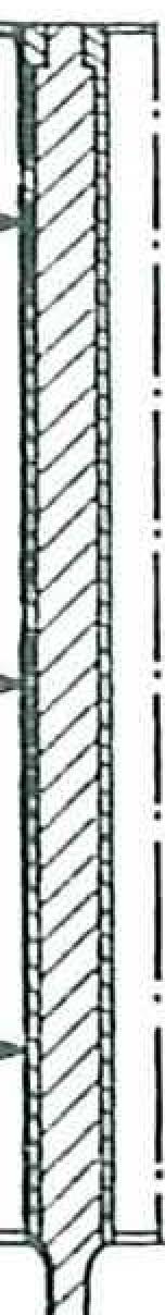
Because of its ductility the cylinder liner must never be measured inside when dismounted; the inner diameter must be measured at completely mounted liner.

@DJ

Loosen the locking screws (I) ofthe collar plate and pull out the camshaft. Pull the valve lifters out oftheir seats and dismount the oil spring nozzles.

Remove the bracket (3) of the transmission gear wheel and the control housing (2).

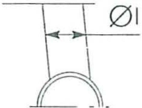
In order to determine the value ofthe out-of-round, ofthe conical form and of the wear the inner diameter of the liners is checked by means of gauge 99395687 (2) provided with centi indicating caliper ( I)that has been previously calibrated at a ring gauge (3) with a diameter of .104 mm.

If a ring gauge with a diameter of I04 mm is not available, use a slide gauge.

( \ ) 8001
0 0
00 0 0
,o

PLAN FOR CHECKING CYLINDER LINER DIAMETER

The measurements must be carried out for each individual cylinder at three different levels in the liner and in two planes at right angles to each other: one parallel to the lengthwise axis (A) and the other at right anglesto it (B). Maximum wear is generally found in this plane (B) and in line with the first measurement. If ovality ortaper or wear of any kind is found, rt may be eliminated at overhaul by grinding the liners ifthe wear or scoring is light, or by reboring and then grinding ifthere is deep scoring or marked ovality.

REPLACING CYLINDER LINERS

Where reconditioning is carried out, all liners must be finished to the same oversize (0.4 - 0.8 mm).

Removal and installation of the cylinder block liners is carried out using a hydraulic press and the appropriate adaptor plate.

To installthe cylinder liners in the cylinder block by using a press, the following steps have to be carried out:

D Measure to ensure cylinder liner outer diameter is I06.970 - I06.940 mm and the cylinder block bore diameter is I06.850 - I06.900 mm;

D Insert cylinder liner· into the cylinder block and test, after pressing-in 70 - 90 mm the load must be not less than 5000 N and not more than 23.000 N;

D Continue pressing in and test, 30 mm before finishing, the load must be between I0.000 and 40.000 N;

D When pressing in is completed, wart 5" with a load of 50.000 or more to ensure liner is fully home; Strike blow with a hammer to ensure the liner is fiush with the cylinder block;

If the fitting load is not within the specific figures, extract the liner and install a new one in its place.

Afterthey have been fitted, cylinder liners must be reamed and ground.

(NOTE: I0.000 N = I Tonne)

Cylinder liners are supplied with an inner diameter slightly below nominal diameter to allow for any deformation which occurs during fitting to be corrected.

Replacement cylinder liners are also supplied wrth the outside diameter 0.2 mm oversize.

8001 Ist MEASUREMENT
MEASUREMENT
MEASUREMENT
2nd
3rd
I ------+ 2 PLAN OF CHAMFER TO BE APPLIED TO CYLINDER LINERS AFTER RECONDITIONING
Crankcase 2. Cylinder liner
I.
Engine p. 26
' /

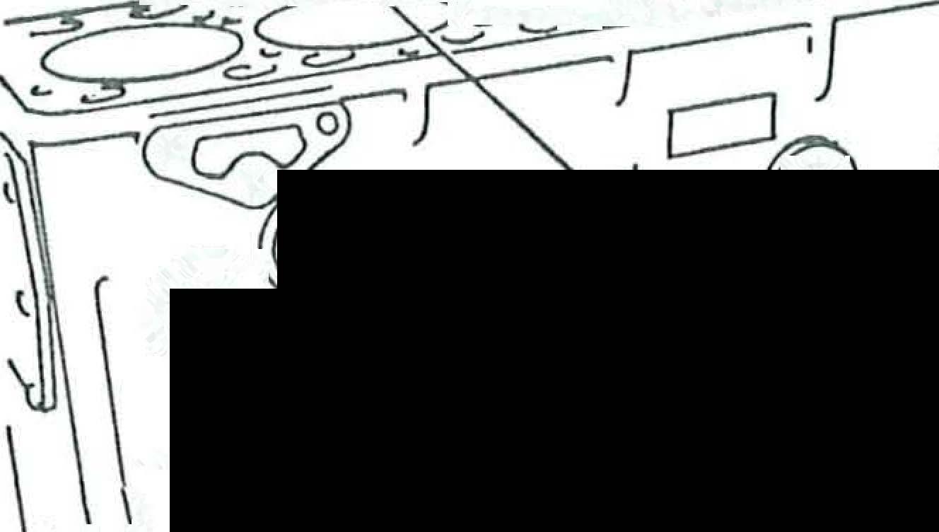
Check the condition ofthe machining plugs (I) in the cylinder block; ifthey are rusted or ther·e is the least suspicion of leakage, replace them.

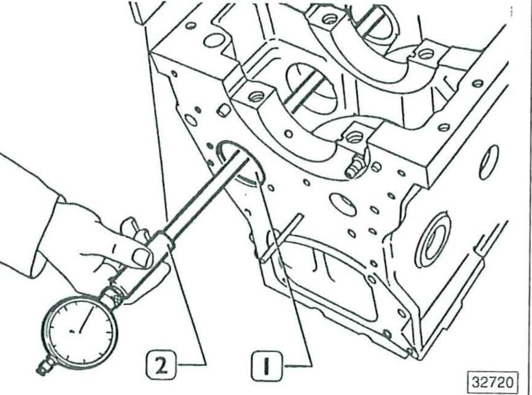
Usingthe tool (I), remove the locating dowel (2) from the mating surface (3) of the cylinder.

Extractthe locating dowel only ifthe mating surface requires skimming.

Check that the cylinder head mating surface (3) are fiat using a calibrate rule (2) and a feeler gauge (I). Grind any rough spots removing as little material as possible after removing the locating dowels.

After grinding the cylinder head surface, restore the proptrusion of the cylinder liner border support base to 0.64 - 0.97 mm

8001 OJ;----.. -�-��_z:�,-:-:_=,_'-';/.::=� <--;::_::::;,:;::::'!=;;:s I; 0 0 0 @ @ <g;Q/Q -�tt_
-----2 I 3l--/4 :.? } \ ·r _) � r--
Engine p. 27

MAIN DATA FOR THE CAMSHAFT

The surfaces of the shaft bearing journals and those of the cams must be absolutely smooth;

CHECKI_NG CAM LIFT AND JOURNAL ALIGNMENT CD

ifthey show traces of seizing and scoring, the shaft and associated bushes must be replaced.

54

1327161

Arrange the camshaft (4) between the centres ( I) and using the hundredths dial gauge (2) check the lift of the cams (3) which should be:

D 5.9"/ mm for the inlet cam

D 6.25 mm for the exhaust cam

7 lili_ii]

To check the assembly clearance, measure the inside diameters ofthe bushes (fig. 57) and the diameter ofthe journals ( I, fig. 54) of the camshaft; the difference will give you the actual clearance. Ifclearances of more than 0.160 mm are found, replace the bushes and the shaft too, if necessary.

REPLACING THE CAMSHAFT GEAR

1327171

Still with the camshaft (4) arranged between centres (I), check the alignment ofthe support journals (3) using the hundredths dial gauge; this must not be more than 0.020 _mm. If a larger misalignment is found, replace the shaft.

Check that the teeth of the camshaft gear (I) are not excessively damaged or worn; if they are, replace it. When frtting the new gear, it should be heated in an oven for IO' at atemper·ature of 180 ° and then shrunk onto the shaft, having first fitted the plate (3) and key (2) to the shaft.

8001 CAMSHAFT s A A Engine p. 28 -.c:::::•··-
/
FIGURE
0 3

8001 BUSHES

The surfaces ofthe bushes must not show any signs of seizing or scoring; ifthey do, r·eplace them.

MAIN DATA FOR CAMSHAFT BUSHES AND THEIR HOUSINGS IN THE CRANKCASE

Dimension to be obtained after the bushes have been installed

REPLACING THE BUSHES

FIGURE 57

Before replacing the bushes (I), measure the bush diameters using a bore micrometer (2).

To remove and refit the camshaft bushes, use a suitable drift.

When fitting the bushes (I), make sure that the holes (2) are lined up with the oil feed holes in the crankcase.

I I
51.580 51,080, 51.630 51.11o 0 Engine
54.375 5U30 0
p.29
\

Afterfitting,reamthecamshaftbushesusingthearbor(I) fitted withthepilotbushes(2)andcutter(3)sothatthespecifiedvalues are obtained.

TAPPETS

Replacement tappets are supplied in standard size and 0.10, 0.20 and 0.30 mm oversizes.

MAIN DATA FOR TAPPETS AND THEIR HOUS INGS IN THE CRANKCASE

Fitting tappets, camshaft

13219s1

Replacingthetappetsbecauseofexcessiveplayinthehausings involves fitting oversize tappets and reaming outthe seatings usingan appropriate reamer (I).

Secure the timinggearcasing (2)tothe crankcase, firstfitting thegasket,andtightenthe screwsto atorqueof25 Nm using atorque wrench. Lubricate the tappets (I) and fit intotheir housings inthe crankcase.

Lubricatethecamshaftbearingsandinserttheshaft(I) intothe crankcase.

8001
CJ )l'-... / :-' '-... 0 !""
REPLACING TAPPETS
Engine p. 30 1 1t 11 _ _J
(

CRANKSHAFT

-.···.·· .! \. 8001
Through the holes (I) in the camshaft gear; tighten the screws (2) securing the camshaft retainer plate to the cr-ankcase. Fit the idler gear pin (3), the injection pump gear (4)
MAIN DATA FOR THE CRANKSHAFT MAIN BEARING JOURNALS AND CRANKPINS Engine p. 31

MEASURING THE MAIN BEARINGS

JOURNALS AND CRANKPINS

Before regrinding the journals, measu1-e the main journals (2) with a micmmeter (I) and establish on the basis of the scale of bearing undersizes (7) the diameter to which the journals must be reground.

The classes of undersize are 0.254, 0.508 mm

1327251

MEASURING THE MAIN BEARING JOURNALS

Main bearing journals and crankpins are always all regmund to the same undersize class so as not to impair crankshaft balance.

Regrinding carried out on main journals or crankpins must be indicated by appropriate markings stamped on the side of crank web no. I

For undersize crankpins :the letter M

For undersize main journals :the letter B

For undersize crankpins and main journals : the letters MB.

MEASURING THE CRANKPINS

During the grinding operation, take great care to comply with the values for the main journal and crankpin blend radii given in the following figures.

8001 Engine p. 32 ,.------------,-------------------------------.------[
----=-ilDlil:mmammmmm::mm:i:llEillzm
DETAIL OF MAIN JOURNAL BLEND RADII 'JETAIL OF CRANKPIN BLEND RADII DETAIL OF THRUST BEARING
.J
MAIN JOURNAL BLEND RADII
1211161

REMOVING/FITTING OILWAY PLUGS

exrneMe ,o,moN o.,s

STANDARD POSITION

JexmMe ,o,moN o,s mm

/325971

Check that the lubrication circuit plugs (2) do not show any leaks at an internal pressure of 15 bars; ifthey do, replace using a suitable drift (I).

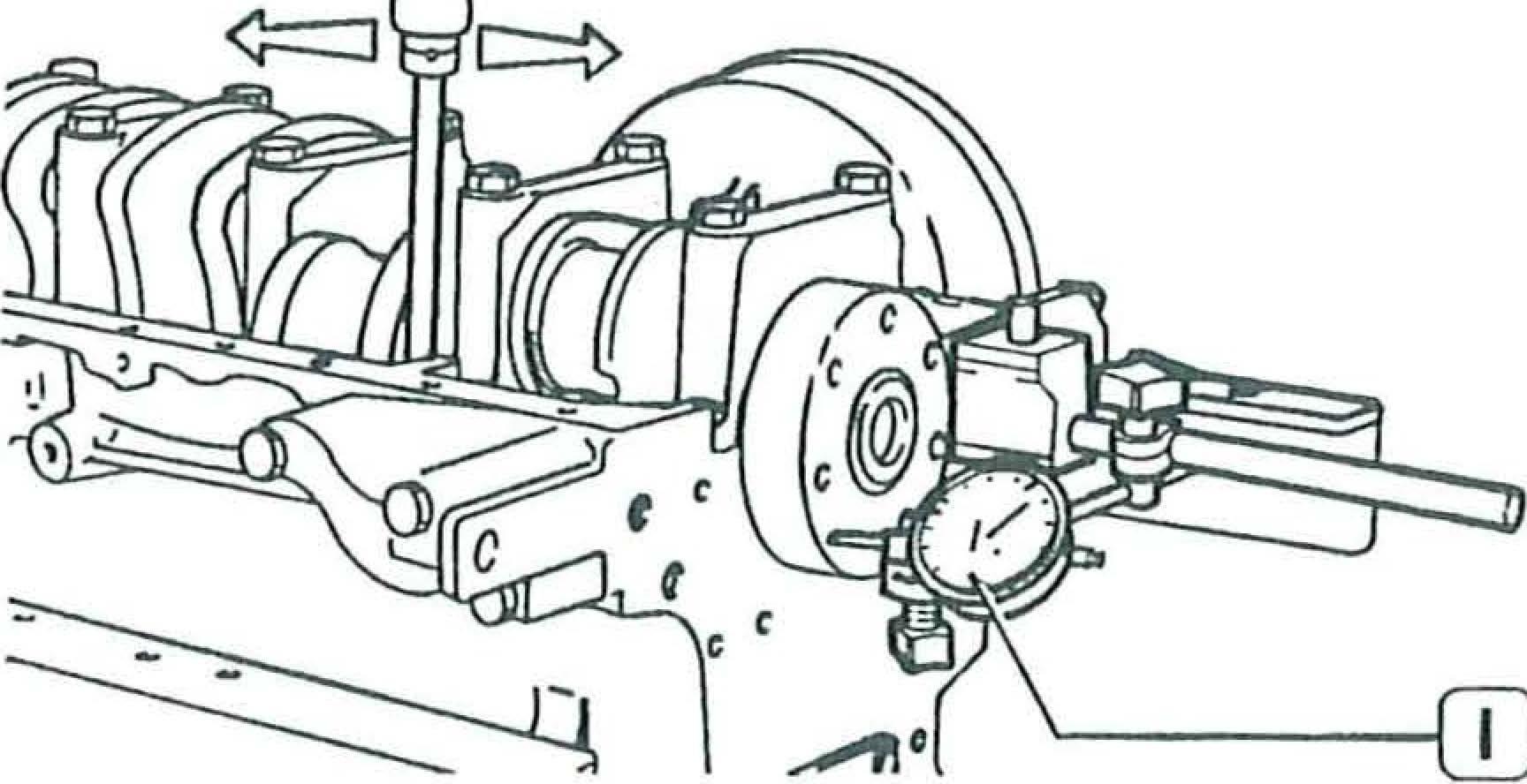
CHECKING MAIN JOURNAL ALIGNMENT

D Alignment ofthe crankpins with the main journals: the c(;ntreline ofeach pair ofcrankpins and the centreline of the main journals must be in the same plane :the maximum tolerance permitted at right angles to this plane is ± 0.25 mm

D Forthe distance between the axis ofrotation ofthe shaft and th.e outersurface ofthe crankpins, the maximum tolerance per·mrtted is ± 0.10 mm

REPLACING CAMSHAFT AND OIL PUMP DRIVE GEARS

/327271

This check must be carr-ied out after· regrinding, if any, of the crankshaft journals by positioning the crankshaft between centres (2) and using a hundredths dial gauge (I) forthe check.

Main journal alignment :maximum tolerance □ > 0.10 mm (total reading on the dial gauge).

/325991

Check that the teeth of the gears (I, 2) are not damaged or worn; ifthey are, remove them using a suitable extractor (3). When fitting new gears (I, 2), they must be heated in an oven for IO' to a temperature of 180° and shrnnk on to the crankshaft, having first fitted the key.

) 8001
Engine p.33
I I : : ,_\\ ./J
@ill
CRANKPIN ·-+ MAIN JOURNAL

MOUNTING MAIN BEARING

Replacement main bearings are supplied in inside diameter undersizes.

MEASURING MAIN BEARING ASSEMBLY CLEARANCES

Do not carry out fitting operations on the bearings.

Position the bearing shells (I) in the main bearing housings in the crankcase.

Lift the crankshaft (2) using tool 99360500 (I) and carefully place it on the bear·ing shells in the housings.

1327301

The clearance between the crankshaft journals and the relevant bearings is checked by the plastigage method, proceeding as follows:

D thoroughly clean the parts and remove all traces of oil

D arrange a strip of plastigage (6) on the main journals (4), parallel with the lengthwise axis

D fit the caps (I) together with the bearing shell to the relevant housings

D fit the cap securing bolts and tighten them to the prescribed torque using a torque wrench; the bolts must be lubricated with oil beforehand remove the caps f rom the housings and determine the clearance between the bearing shells and the crankshaft main journals by comparing the width of the plastigage at the point of greatest flattening with the scale divisions given on the package (3) containing the plastigage

Checking crankshaft end float

The normal assembly clearance is 0.082 - 0.334 mm. Ifa larger end float is found, replace the thrust washer halves with new ones of standard thickness or ifnecessary an oversize of 0.127, 0.254, 0.508 mm.

8001
I I

Further

Engine p.35

The bolts must be lubricated.

1327791

8001
Position the thrust washer halves (I) on the 6th housing with the su,iace covered with anti-friction alloy towards the facing on the crankshaft. 132731I Fit the main bearing caps with bearing shells; before fitting the cap (I), position the halves of the thrust washer (2) with the surface covered with anti-friction alloy towards the facing on the crankshaft. Using a torque wrench (I), tighten the securing bolts (2) to a torque of 80 Nm.
OJ-----.... .....
tighten the screws by 90 ° , using tool 99395216 (I). 1327331 Fit the dial gauge ( I) with magnetic base and check end fioat.

Fitting the flywheel CRANKSHAFT REAR COVER

The bolts may be re-used provided thatthe 0 ofthe thread is not less than I 1.5 mm.

The oil seal (2) is fitted to the cover (I) using the appropriate installing tool (3).

Fit the fiyw heel (I), fit tool 99360352 (2) and, using a torque wrench, tighten the bolts (3) previously coated with LOCTITE HVX 576 to a torque of 40 Nm.

Fit the rear cover ( I) to the crankcase, having first fitted the gasket.

FLYWHEEL

Check the surface on which the clutch plate bears; if it is scored, skimming will be required.

REPLACING THE FLYWHEEL RING GEAR

Ifthe teeth ofthe gearfitted to the fiyw heelare badly damaged, replace the ring gear. Before fitting, the gear must be heated to a temperature of 80° C

Fittool 99395216 (I) and furthertighten the screws (2) by 60° Remove the fiyw heel locking tool (3).

CONNECTING ROD/PISTON ASSEMBLY

COMPONENT PARTS OF THE CONNECTING ROD/PISTON ASSEMBLY

I.Retaining clips

2.Gudgeon pin 3.Piston 4.Piston rings

5.Bolt 6.Bearing shells 7.Connecting rod 8.Bush

8001 Engine p. 36 ------------------------------------------ ·•:•.:_

1326131

Remove the pi�ton rings (I) f rom the piston (2) using tongs 99360183 (3).

The diameter must be measured 12 mm from the base of the skirt.

1326141

The gudgeon pin (I) retaining clips (2) are removed using a scriber (3) as shown in the figure.

PISTON

Replacement pistons are supplied in standard size or 0.4, 0.8 mm oversizes.

Measuring the piston diameter

The diameter ofthe piston ( I) is measured using a micrometer (2) to determine the assembly clearance.

1326161

The clearance between the piston and cylinder liner can also be measured using a feeler gauge (I).

GUDGEON PIN

The pins are fitted with clearance both in the small end and in the piston.

1326181

The diameter ofthe pin (I) is measured using a micrometer(2).

: ' 8001
Engine p. 37

Engine p. 38 -<r..

Conditions for a correct gudgeon pin to piston fit

PISTON RINGS

Replacement piston rings are supplied in standard size and 0.4, 0.8 mm oversize.

OJ-----------,, [[)---

When fitting new pins, check the correct fit with the housing in the piston by carrying out the following check:

lubricate the pin and its housing in the piston bosses with engine oil holding the pin in a vertical position, insert it into the bosses in the piston it should be possible to insert the pin simply by pressing on it the pin should not drop out of the bosses by itself 4,030 4,05 0

I165521

Check the thickness of the piston ring (2) using a micrometer (I).

3,075* 3,095 2.478 2.490 37,984 37,99 0 3,975 3,990 103,852 103,870

8001
D D D D PISTON 3, 200 * 3,230 2.570 2,55 0 38,00 0 38,006
MAIN DATA FOR THE PISTON, PISTON RINGS AND GUDGEON PIN * The dimension is measured on a 0 IO I mm.

1326201

Check

1327371

The clearance between the ends of the piston rings (I) inserted into the cylinder liner (3) is measured using a feeler gauge (2).

If the gap between the ends is found to be less or more than the specified value, replace the piston rings.

CONNECTING RODS

§1

The compression ring (2) in the first slot is wedge shaped. The clea,-ance between the compression ring and the groove is measured by positioning the piston (I) with the relevant ring in the cylinder liner (3) in such a way that the compression ring half projects from the cylinder liner.

MAIN DATA FOR THE CONNECTING ROD, BUSH, GUDGEON PIN AND BEARING SHELLS

*Dimension to be obtained after installing the bush.

I \ 8001
the clearance between the piston rings (3) and the grooves on the piston (2) using a feeler gauge (I).
Engine p. 39.
0
38,004 38.014

Checking connecting rods for distortion

Reamingthe small end bush using reaming machine 9930 I044.

ASSEMBLING THE CONNECTING ROD/ PISTON ASSEMBLY

Assembling connecting rod to piston

132738

Check thatthe connecting rod axes are parallel. The tolerance permitted is 0.07 mm measured at 125 mm from the lengthwise axis ofthe rod.

Each connecting rod is marked on the body and cap with a number corresponding to that ofthe cylinder to which it is fitted. In case ofreplacement, it is therefore necessary to number the new connecting rod with the same number as the one replaced.

BUSHES

The bush (2) is removed and refitted usingthe appropriate drift (I).

The piston (2) must be fitted so that the words TAPPET SIDE (I) on the crown are on the opposite side to the number (4) engraved on the connecting rod. Insert the gudgeon pin (3) and frt the retainer snap rings.

Checking connecting rod/piston for distortion

After installing the bush in the connecting rod small end, remove the part which protrudes at the side and then ream the bush to the specified diameter.

Checkthe connecting rod-piston assembly fordistortion using fixture 99395363 (I) and a feeler gauge (2). The plane ofthe piston crown must be exactly at right anglesto the plane ofthe fixture 99395363.

8001
p.40
Engine

8001

Fitting piston rings

1326131

The piston rings (I) are fitted to the pistons (2) using tongs 99360183 (3). The rings must be fitted with the word TOP facing upwards, and also the ring gaps must be located so that they ar·e I20° apart from each other.

132631I

PLAN FOR ASSEMBLING THE CONNECTING ROD TO THE PISTON FOR FITTING THE ASSEMBLY INTO THE CYLINDER

I.Piston 2.Combustion chamber 3.Area stamped with the number of the cylinder to which the connecting rod belongs 4.Camshaft

The arrow indicates the direction of rotation of the engine viewed from the camshaft drive end.

1326301

Fit the bearing shells (I) to the connecting rod and to the cap.

Do not carry out any fitting operations on the bearing shells.

PSMilNWA!H

The connecting rod bolts may be reused provided that the 0 of the thread measured between 19 and 35 mm from the beginning ofthe screw is not lessthan 10.5 mm.

l32632I

The connecting rod/piston assembly (I) is fitted into the cylinder liner using ring clamp 99360605 (2). Lubricate the parts concerned before fitting.

When fitting the connecting rod/piston assemblies into the liners, check that:

□ the connecting rod number corresponds to the number of its cylinder

0 the words TAPPET SIDE stamped on the crown are facing the camshaft

□ the numbers on the connecting rods are facing away from the camshaft side

D the piston ring gaps are staggered I20° from each other.

I
Engine p.41
·--------···· ..

MEASURING CRANKPIN ASSEMBLY CLEARANCE

To measurethe clearance, carryoutthe following operations :

D thoroughly cleanthe parts and remove alltraces ofoil position astripofplastigage (2) onthe crankshaftjournals

fitthe connecting rod cap (3) andtightenthe boltstothe D prescribedtorque;the bolts mustbe lubricated remove the cap (3) and determine the clearance by □ comparingthe width ofthe plastigage (2) atthe point of greatest flattening with the scale divisions given on the package (3) containingthe plastigage.

Lubricatethe parts concerned before final assembly. Beforere-usingtheconnectingrodcapsecuringbolts, checkthatthediameterofthethreadmeasuredat 19 - 35 mm from the beginning ofthe screw is not less than I0.5 mm; ifit is, replacethe bolt

Fitting connecting rod caps

1327401

Fittool 99395216 (I) tothedialwrench andtightenthe bolts (2) furtherby 60°

Checkthatthe connecting rods can be moved axially on the crankpins.

1327391

Fittheconnectingrodcaps (2)and,usingatorquewrench (I), tightenthe bolts (3)toatorque of40 Nm; the bolts mustbe lubricated beforehand.

When fittingiscomplete, checkthe position ofthe pistons(4) atTDCwithrespecttothecylinderblockfaceusingadialgauge (2) with magnetic base (3).

The top lands ofthe pistons must project 0.64 - 0.97 mm abovethe face ofthe cylinderblock (I).

TIMING GEARS

CHECKING AND REPLACING THE IDLER GEAR

Checkthe idlergearfordamageandexcessivetooth wear,replacingit ifnecessary.

8001
□ (I)
-:::-: .::-_Engine p. 42 .·-·• LTI-0
===========--= c=
':.':..':..':..':_':_==.__ = --i

Engine p. 43

TIMING CONTROL

REPLACING THE IDLER GEAR BUSH

132637I

The timing check is carried out as follows:

□ provisionally set the play between the valves and rockers at 0,30 mm and check with a graduated sector that the advance and retard angles for intake and exhaust correspond to those indicated in the page 1 for engine 8061Si ... ; and page 2 for engine 8061SRi

Install the idlergear (2), locating it so that the numbers I, 2 and 3 marked on it line up with the same numbers engraved on the crankshaft gear (I), the camshaft gear (3) and the injection pump gear (4).

8001
--tt- --i-i---ni---.0
""'""' 0,2+0,55 1,8 +2
Check the contact surfaces ofthe bush (I) for scoring or signs ofseizing; ifthese are found, replace the bush using a suitable drift.
*irlo M-0
MM
1326381
After fitting the bush (I), it must be reamed to the diameter shown in the figure (*).

CYLINDER HEAD

(6, fig. 121) so that the valve collets (4) can be extracted and the valve released; take off the upper cup (6), the spring (3) and the lower cup (5). Repeat the operation on all the valves. Turn the cylinder head upside down and withdraw the valves.

1327431

COMPONENT PARTS OF THE VALVE ASSEMBLY

I.Exhaust valve 2.lnlet valve 3.Spring 4.Collets

5.Lower cups 6.Upper cups

1327441

Before dismantling the cylinder head, carry out the hydraulic leak test using the appropriate equipment (I, 3). By means of the coupling (3), pump in water heated to approx. 90 , to a pressure of4- 5 bars. Underthese conditions, no leaks should be found, and ifthey are, the cylinder head (2) should be replaced.

DISMANTLING THE VALVES

Checking the mating surface of the head with the cylinder block

Rest the cylinder head on the workbench and, using tool 99360357 (I), apply pressure to the upper spring cup

The mating surface of the head with the cylinder block is checked using a straight edge and a feeler gauge. Ir values of morethan 0.15 mm ar·e found overthewhole length ofthe surface, true up the head on a suitable surface grinder, removing as little material as possible.

After this operation, the recessing ofthe valves and protrusion ofthe injectors should be checked.

8001
Hydraulic leak test
Engine p.44 ./="·
-f------J2
FIGURE 121

8001 VALVES

Removal of deposits and inspection of valves

Refacing the valves

Engine p.45

Ifnecessary, reface the s_eatings on the valves using grinding machine 9930 IO 14, setting an angle of 455 30' " 7' for· exhaust valves and 605 30' "T for inletvalves, removing as little material as possible.

Checking the play between a valve stem and its valve guide

Remove carbon deposits from the valves using a suitable wire brush.

Check the valves for signs ofseizing or cracking and also, using amicrometer; checkthatthe diameterofthe valve stem is within the specified limits (see fig. 124). If not replace the valves.

MAIN DATA FOR VALVES AND VALVE GUIDES

* Dimension to be obtained after installing the valve guides.

Using a dial gauge (2) with magnetic base (I), check the play between the valve stem (3) and its guide. If excessive play is found, replace the valve and, if necessary, the valve guide.

VALVE GUIDES

1327481

The valve guides are removed and fitted using drifts 99360288 and 99360293.

Replacement valve guides are also supplied with the outside diameter 0.2 mm oversize.

I186251
FIGURE 124 -------1 7, 9 8 5 1--------f'=i--8. 0 00 -U---W---' 13.993 14.016 8 0 Z3·---.-18. 0.(.3 60" 30'-t]' 45. 30•! 7' 1--------' INLET EXHAUST

VALUES FOR INSTALLING VALVE GUIDES

Recutting the valve seats

Reaming the internal surfaces of valve guides

Using the Hunger tool 99360419 (I), recut the valve seats in the cylinder head so as to obtain perfect sealing.

Thevalve seats in the cylinderhead are recut whenever the valves or valve guides are reconditioned or replaced.

REFERENCE 0

MAIN DATA ON THE INLET AND EXHAUST VALVE SEATINGS

When assembling after the recutting operations, check that the recessing of the inlet and exhaust valves with respect to the cylinder head face is 0.7I mm.

1327961

After installingthe valve guides, ream the hole in the valve guide (2) using reaming tool 99390310 (I).

8001 MAX2
Engine p. 46 /--"··-
INLET
EXHAUST
0,7+1 VAL RECESSING
(

Valve leakage test

1327501

The leakage test on the valves in the cylinder head (I) is carried out using the appmpriate equipment (2 and 3).

VALVE SPRINGS

Refitting the valves

1327451

To fit, reverse the order of the operations carried out for removal as described.

Lubricate the valve stems with engine oil.

Fitting the cylinder head

I165871

Befor-e fitting, the characteristics of the valve sp,-ings must be checked using tool 99305049, and the data on load and elastic deformation compared with those given for new springs in the following figure.

N270 ±14

N 528 ±26

1203981

I189291

Before re-using the cylinder head bolts (2), with a micrometer ( I) measure that the thread diameter of the bolts is not less than I 1.5 mm at any point if it is, replace them.

8001
MAIN DATA FOR CHECKING THE VALVE SPRINGS Engine p. 47 .
OJ
-•--.·------·---·.----·------·I·

1327521

To fit and tighten down the cylinder head, follow the instructions given below :

D arrange the gasket ( I) on the crankcase wrth the word ALTO [TOP] (2) facing the operator

PUSH RODS

D fitthe cylinder head (2), insertthe bolts (3) after lubricating them and tighten them as follows in the sequence shown in figure I37.

D stage I :using atorque wrench (I), tighten to the preliminary torque of 70 Nm

D stage 2 : retighten to the torque of 70 Nm

1326551

The valve pushrods must be free from distortion; the cup seatings forthe adjustment screws and the ball ends locating in the tappets must not show any signs ofseizing or wear; ifthey do, replace the rods.

Pushrods for inlet and exhaust valves are identical and therefore interchangeable.

8001
0 0 0 0 0 0
PLAN SHOWING CYLINDER HEAD BOLT TIGHTENING SEQUENCE 22
FIGURE 137 20 12 ( 5 13 21
19 11 11.
I 69351
······-· ·-····· -:-:-.-:-.:--:-:-:- -:-.--:-:.- -·--.·.-. -·-:.:.-:-----·.·-·. Engine p. 48 1 [0----'
D stage 3 :fittool 99395216 (I) to the angle gauge wrench and tighten by an angle of I80°
,, 1J
Fit the pushrods (I) into their seatings.

PUSH RODS

COMPONENT

MAIN DATA FOR P.OU�l:R SH/\FT PEDESTALS, ROCKER SHAFT AND ROCKERS

Check that the contact surfaces are free from scoring or signs of seizing; if not, replace the parts showing deterioration.

Check the clearance between the valve gear rockers and the rocker shaft and between the pedestals and rocker shaft, which should be 0.016-0.052 and 0-0.061 mm respectively; replace any parts giving rise to clearances larger than those specified.

Check that the plugs fitted to the ends of the shaft provide a perfect seal.

Fitting the rocker shaft and adjusting the operating clearance between the valves and rockers

8001
PARTS OF THE ROCKER SHAFT 1.Circlip 2.Adjustment shims 3.Rockers 4.Pedestal for shaft 5.Spring 6.Shaft ROCKER SHAFT 17,982 18,000 18,016 18,034 Engine p.49 18,000 18,01.3
Fit the caps (I) onto the valve stems.

Frt the rocker shaft assembly (I).

Adjust the operating clearance between the valves and rocker-s as described below.

LUBRICATION

Engine lubrication is obtained by means of a gear- type pump (fig. 147) frtted to the lower part of the crankcase in line with the front main bearing; it is driven by the crankshaft gear;

OIL PUMP

J327sal

The clearance between the rockers and valves is adjusted using wrench 99350 I08 (2), a bi-hexagon wrench (I) and a feeler gauge (3). The operating clearance is 0.25 ± 0,05mm for both inlet and exhaust; subsequent adjustments are carried out when a value outside the range 0.15 - 0.45 mm is found. Move the cylinder on which the clearance is to be adjusted to the firing position; the valves of this cylinder are closed while those ofthe symmetrical cylinder are rocking. Symmetr-ical cylinders ar-e I and 6, 2 and 5 and 3 and 4.

To speed up adjustment ofthe rocker to valve operating clearances, proceed as follows : rotate the crankshaft until the valves of no. I cylinder are rocking and adjust the valves marked with an asterisk as shown in the table :

cylinder no. 2 3 5 inlet exhaust

rotate the crankshaft until the valves of no. 6 cylinderare rocking and adjust the valves marked with an asterisk as shown in·,the table :

2 3 4 ' 5 6

8001 � �
cylinder no. inlet exhaust Engine p. 50 ::::--·
OIL PUMP ASSEMBLY I.Pump body 2.Relief valve 3.Driven gear 1325521
FIGURE 147

Checks

Check that the gears (5, 17 fig. 148) and gear wheel (7) show no signs of wear or seizing; if they do, replace the complete pump.

Checkthat the valve (I I, fig. 148) slides freely in its housing and shows no signs ofseizing or scoring; also checkthe setting data for the relief spring (I0) compared with those given in figure 151.

Valve starts to open :6 bars; valve finishes opening : I I bars

8001 Engine p. 51 FIGURE 148 9 COMPONENT PARTS OF THE OIL PUMP ASSEMBLY I.Screw 2.Washer 3.Locating dowel 4.Bush 5.Oil pump gear 6.Locating dowel 7.Dr-iven gear operating the oil pump 8.Seal 9.Valve body I0.Spring I I.Valve 12.Screw 13.Washer 14.Attachment plate 15.Oil pump body 16.Bush 17.Oil pump gear 18.Bush 19.Spindle 20.0il pump cover r-··ui I �-'! I EJ
SECTIONAL
OIL
SECTIONAL VIEW OF OIL PUMP
VIEW OF
PRESSURE RELIEF VALVE
FIGURE 151
MAIN DATA FOR CHECKING THE RELIEF VALVE SPRING

OIL FILTER

Two double filtration filters are fitted to the engine. Opening pressure for the filter valve :2.5 ± 0.2 bars.

COOLING WATER PUMP

The water pump is ofthe centrifugal impeller type. The pump bearing is integral wrth the rotor spindle.

Water sealing between the pump body (4, fig. 154) and the spindle (2) is obtained by means of a seal (5).

The screw (3. fig. 154) retaining the bearing must be locked in its housing using LOCTITE 242 sealant.

SECTIONAL VIEW OF THE OIL FILTER

When fitting the filters, observe the following instructions:

- oil the seals

- screw the filters up until the seals contact the seating bases

- tighten further for another 3/4 of a turn

I.Hub 2.Spindle with bearing 3.Screw 4.Pump body 5.Seal 6.Cover ?.Rotor

Check that the pump body has no cracks or water leaks; if it has, replace the water pump complete.

8001
Fitting the oil pump
Engine p. 52 / ••-
Fit the oil pump (2), the suction (I) and delivery (3) pipes.
FIGURE 154 SECTIONAL VIEW OF WATER PUMP

MOUNTING OF THE INJECTION PUMP AND TIMING (FOR ENGINES WITH ROTARY INJECTION PUMP)

Fit the injection pump, proceeding as follows 0 check that the timing gears are set correctly

D install the injection pump (I), lining up the double recess inside the drive coupling with the double dog in the sleeve

D screw up the screws without tightening them fully

Engine

screw on tool 99395099 (2) complete with the hundredths dial gauge (I) with the stylus in contact with the crown ofthe control piston apply 3 mm preload to the dial gauge turn the engine backwards until the control piston on the pump reaches BOC as indicated by the dial gauge zero the dial gauge

□ remove the plug (I) on the pump closure screw ImMj

□ turn the engine forwards and bring the.8 ° ± 30' mark (2) engraved on the fiywheel, indicating injection advance,1into line with the reference pointer (I)

D under these conditions, the control piston of the pump should have travelled I mm, the value being read offfrom the dial gauge Ifthis is not the case, rotate the pump body in its slotted hole until the specified value is obtained

D fully tighten the pump securing screws

o remove tool 99395099 and screw the plug back into the closure screw.

.I
8001
□ □ □ □
p. 53

MOUNTING OF THE INJECTION PUMP AND TIMING (FOR ENGINES WITH ROTARY INJECTION PUMP)

Fit the injection pump, proceeding as follows : D check that the timing gears are set correctly

Engine p. 54

D install the injection pump (I), lining up the double recess inside the drive coupling with the double dog in the sleeve

.0 screw. up the screws without tightening them fully

screw on tool 99395099 (2) complete with the hundredths dial gauge (I) with the stylus in contact with the crown of the control piston apply 3 mm preload to the dial gauge turn the engine backwards until the control piston on the pump reaches BOC as indicated by the dial gauge zero the dial gauge

I 32764I

D turn the engine forwards and bring the. 3 ° ± 30' mark (2) engraved on the flyw heel,indicating injection advance,1into line with the reference pointer (I)

D under these conditions, the control piston of the pump should have travelled I mm, the value being read off from the dial gauge. Ifthis is not the case, rotate the pump body in its slotted hole until the specified value is obtained

D fully tighten the pump securing screw�

D remove tool 99395099 and screw the plwg back into the closure screw.

8001
D D D D
D remove the plug ( I) on the pump closure screw

Engine p.

OVERHAUL OF THE ELECTRIC MACHINE

About the operations of dismantling. overhaul. re-fitting of the components of the electric machine. please refer to the specific manual supplied with each genset.

REASSEMBLING THE ENGINE

Frtthe timing gear cover (3). Frt tool 99360352 to the fiyw heel to prevent rt from rotating.

Frtthe hub (I) wrth locking plate; tighten the nut wrth atorque wrench (2) to a torque of 300 Nm and bend over the locking plate (4).

8001
jnml
55
Fit the water pump ., the thermostat unrt ., damper fiywheel (5), pulley (6) 1m611 Frt the fan mounting (I)

Engine p. 56

Turn the engine through 180 ° , position the gaskets, coat with sealant at the joints; fit the sump (I), the fan duct support and the bracket for the heat exchanger cooling pipes.

For engines with in-line injection pump: ·Fit the flywheel cover(l).the inlet manifold (2).the injection pump(3). with the fuel filter(5). injectors lines;

For engines with rotary injection pump: Fit the flywheel cover(l).the inlet manifold (2).the injection pump(3). with the fuel fiHer(5). injectors lines; the actuator.

8001
Fit the belts tensioner; water pump pulley.Cl) the pipe from the water pump to the radiator. Fit ti belts (3) and the alternator (4) Fitthe injectors (I), securing them with the brackets (2), fitthe fuel return pipe (3) and the rocker cover (4) with gasket.
I I ·- "" 0 o 0 ::::=-® .. --::-
( (

Fit the heat exchanger (1) and the two connecting pipes: the oil filters(2): the turbocharger(4). the oil delivery and retur pipes

Fit radiator ,ith the relevant connection pipes(l) ,and guard for fan and alternator:air cleaner(2):electric machine (3):electric wiring.

Complete all these operations assembling the relevant lines.

Refill the engine oil sump according to the indicated quantities.

ASSEMBLING OF THE ALTERNATOR WITH THE ENGINE

For the alternator fitting carry out the following operations:

- Place the flex-plate of the alternator on the flywheel centering.

- Block the fixing screws of the alternator bell to the : engine.

- Block the fixing screws of the flex-plate to the flyheel.

) 8001
Engine p. 57
-·--) '\ ..:::.· --,-----•-:-> --------- -·--·-
Issuu converts static files into: digital portfolios, online yearbooks, online catalogs, digital photo albums and more. Sign up and create your flipbook.