RC1827
SUBMITTED BY
CREATED ON 2024-01-24
Boiler Information
Boiler Type
Property Information
Does The Property Have a Valid EPC?
No
LOCATION Total area 179.14 m² Floors 3
▼
THIS FLOOR PLAN IS NOTTO SCALE AND IS FOR VISUAL REPRESENTATION ONLY.
PLEASE NOTE, SOME MEASUREMENTS PRESENT MAY NOT BE ACTUAL MEASUREMENTS - REGENERTEC CONSULTING OBTAIN MEASUREMENTS FOR INTERNAL AND EXTERNAL WALLS FOR THE PURPOSES OF COMPLETING HEAT LOSS CALCULATIONS ONLY. ALL OTHER MEASUREMENTS ARE FOR GUIDANCE ONLY AND REGENERTEC CONSULTING ACCEPT NO LIABILITY FOR THE ACCURACY OF THESE
Ground Floor TOTAL AREA: 88.65 m² •LIVING AREA: 75.85 m² • 32 26 30 27 28 29 31 UFH Manifold 24 5 3 4 2 36 35 7 17 22 21 13 16 18 19 20 15 Roof Lantern 780x570 37 38 41 39 40 12 Solar PV Inverter & Batteries 10 9 8 Party Wall 1 2 48 2 48 1.70 3.50 0 69 0 88 0 86 2 43 7.35 3.18 0.95 1.30 1.14 3.39 1.04 1.66 0.90 2.10 1.78 1.35 0.62 3.40 3.73 2.17 2.51 5.17 Kitchen / Dining Room 27.58 m² (4.91 × 7.35) Cupboard 1.77 m² 1.39 × 1.47 Bedroom 4 / Study 10.50 m² (3.39 × 3.18) Shower Room 4.32 m² (2.23 × 2.37) Cupboard 0.73 m² Hall 17.74 m² (5.93 × 6.00) Sitting Room 13.26 m² (3.40 × 4.31) Garage 12.81 m² (2.52 × 5.17)
ALTERNATIVE PURPOSES. Page 2/59
MEASUREMENTS IF USED FOR
▼ Ground Floor
1 HEAT PUMP
Dimensions
0.80 m x 0.80 m x 0.40 m (Width x Depth x Height)
Photo
1 Photo (see photos page)
THIS FLOOR PLAN IS NOTTO SCALE AND IS FOR VISUAL REPRESENTATION ONLY. PLEASE NOTE, SOME MEASUREMENTS PRESENT MAY NOT BE ACTUAL MEASUREMENTS - REGENERTEC CONSULTING OBTAIN MEASUREMENTS FOR INTERNAL AND EXTERNAL WALLS FOR THE PURPOSES OF COMPLETING HEAT LOSS CALCULATIONS ONLY. ALL OTHER MEASUREMENTS ARE FOR GUIDANCE ONLY AND REGENERTEC CONSULTING ACCEPT NO LIABILITY FOR THE ACCURACY OF THESE MEASUREMENTS IF USED FOR ALTERNATIVE PURPOSES. Page 3/59
▼ Photos/Ground Floor 1 Heat Pump THIS FLOOR PLAN IS NOTTO SCALE AND IS FOR VISUAL REPRESENTATION ONLY. PLEASE NOTE, SOME MEASUREMENTS PRESENT MAY NOT BE ACTUAL MEASUREMENTS - REGENERTEC CONSULTING OBTAIN MEASUREMENTS FOR INTERNAL AND EXTERNAL WALLS FOR THE PURPOSES OF COMPLETING HEAT LOSS CALCULATIONS ONLY. ALL OTHER MEASUREMENTS ARE FOR GUIDANCE ONLY AND REGENERTEC CONSULTING ACCEPT NO LIABILITY FOR THE ACCURACY OF THESE MEASUREMENTS IF USED FOR ALTERNATIVE PURPOSES. Page 4/59
▼
▼
2
4 / Study/Ground Floor
Bedroom 4 / Study Ground Floor WIDTH: 3.39 m •LENGTH: 3.18 m • CEILING HEIGHT: 2.31 m AREA: 10.50 m² • PERIMETER: 13.14 m Party Wall 0 80 1.14 0.80 1.05 2.25 3.18 0.95 1.30 1.14 3.39 2.93 5 3 4 6 2
Bedroom
FRENCH WINDOW Dimensions 1.30 m x 1.16 m (Width x Height) Distance to Floor 1.00 m 3 HINGED DOOR Dimensions 0.80 m x 2.04 m (Width x Height) Distance to Floor 0.00 m
HINGED DOOR Dimensions 0.80 m x 2.04 m (Width x Height) Distance to Floor 0.00 m THIS FLOOR PLAN IS NOTTO SCALE AND IS FOR VISUAL REPRESENTATION ONLY. PLEASE NOTE, SOME MEASUREMENTS PRESENT MAY NOT BE ACTUAL MEASUREMENTS - REGENERTEC CONSULTING OBTAIN MEASUREMENTS FOR INTERNAL AND EXTERNAL WALLS FOR THE PURPOSES OF COMPLETING HEAT LOSS CALCULATIONS ONLY. ALL OTHER MEASUREMENTS ARE FOR GUIDANCE ONLY AND REGENERTEC CONSULTING ACCEPT NO LIABILITY FOR THE ACCURACY OF THESE MEASUREMENTS IF USED FOR ALTERNATIVE PURPOSES. Page 5/59
4
▼ Bedroom 4 / Study/Ground Floor
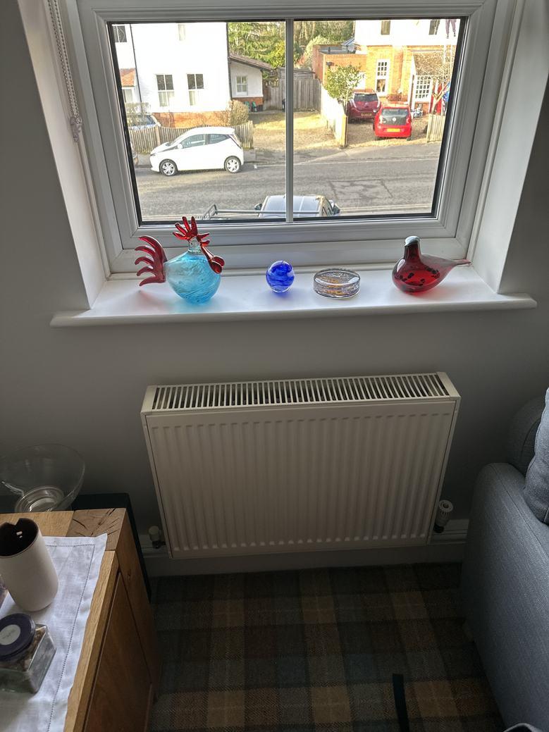
5 WATER RADIATOR
Dimensions
0.60 m x 0.60 m (Width x Height)
Distance to Floor 0.00 m
Photos
2 Photos (see photos page)
Radiator Information
Radiator Type 22
Height 600
Width 600
THIS FLOOR PLAN IS NOTTO SCALE AND IS FOR VISUAL REPRESENTATION ONLY. PLEASE NOTE, SOME MEASUREMENTS PRESENT MAY NOT BE ACTUAL MEASUREMENTS - REGENERTEC CONSULTING OBTAIN MEASUREMENTS FOR INTERNAL AND EXTERNAL WALLS FOR THE PURPOSES OF COMPLETING HEAT LOSS CALCULATIONS ONLY. ALL OTHER MEASUREMENTS ARE FOR GUIDANCE ONLY AND REGENERTEC CONSULTING ACCEPT NO LIABILITY FOR THE ACCURACY OF THESE MEASUREMENTS IF USED FOR ALTERNATIVE PURPOSES. Page 6/59

▼ Photos/Bedroom 4 / Study 5 Water Radiator Photo 1 5 Water Radiator Photo 2 THIS FLOOR PLAN IS NOTTO SCALE AND IS FOR VISUAL REPRESENTATION ONLY. PLEASE NOTE, SOME MEASUREMENTS PRESENT MAY NOT BE ACTUAL MEASUREMENTS - REGENERTEC CONSULTING OBTAIN MEASUREMENTS FOR INTERNAL AND EXTERNAL WALLS FOR THE PURPOSES OF COMPLETING HEAT LOSS CALCULATIONS ONLY. ALL OTHER MEASUREMENTS ARE FOR GUIDANCE ONLY AND REGENERTEC CONSULTING ACCEPT NO LIABILITY FOR THE ACCURACY OF THESE MEASUREMENTS IF USED FOR ALTERNATIVE PURPOSES. Page 7/59
▼
Cupboard Ground Floor WIDTH: 1.25 m •LENGTH: 0.59 m • CEILING HEIGHT: 2.31 m AREA: 0.73 m² • PERIMETER: 3.68 m Party Wall 1.05 1.25 0.59 1.25 0.59 7
▼
Cupboard /Ground Floor
DOUBLE HINGED DOOR Dimensions 1.05 m x 2.04 m (Width x Height) Distance to Floor 0.00 m THIS FLOOR PLAN IS NOTTO SCALE AND IS FOR VISUAL REPRESENTATION ONLY. PLEASE NOTE, SOME MEASUREMENTS PRESENT MAY NOT BE ACTUAL MEASUREMENTS - REGENERTEC CONSULTING OBTAIN MEASUREMENTS FOR INTERNAL AND EXTERNAL WALLS FOR THE PURPOSES OF COMPLETING HEAT LOSS CALCULATIONS ONLY. ALL OTHER MEASUREMENTS ARE FOR GUIDANCE ONLY AND REGENERTEC CONSULTING ACCEPT NO LIABILITY FOR THE ACCURACY OF THESE MEASUREMENTS IF USED FOR ALTERNATIVE PURPOSES. Page 8/59
7
▼
▼ Garage/Ground Floor
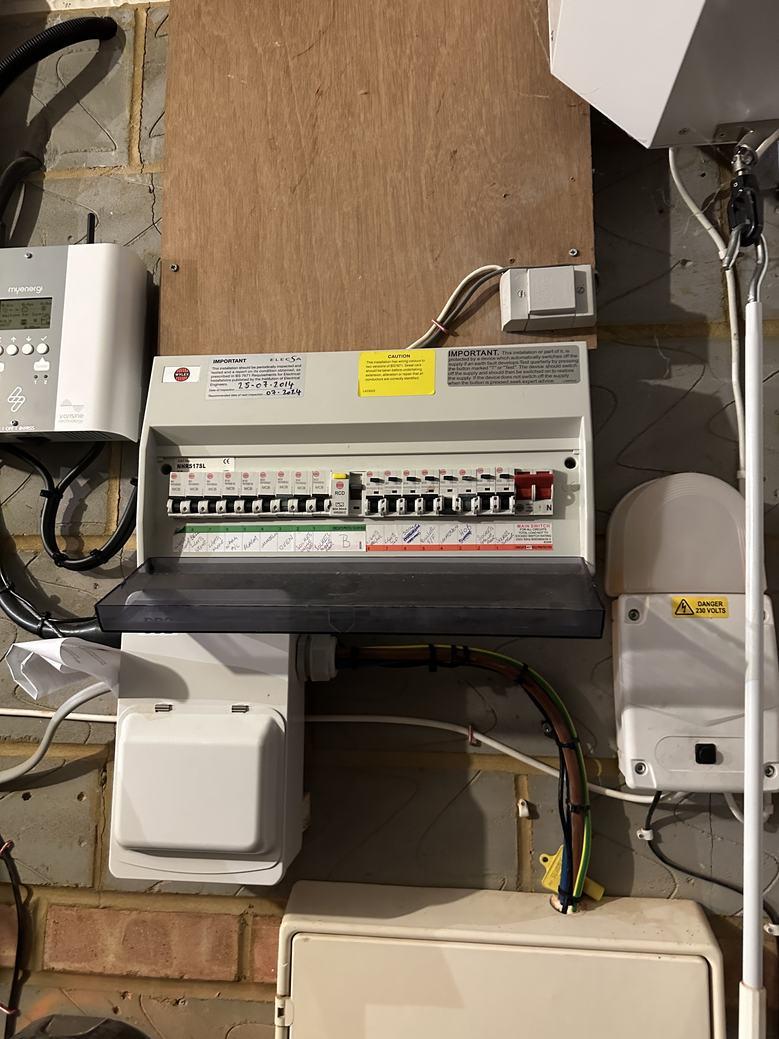
8 BREAKER BOX
Photos
6 Photos (see photos page)
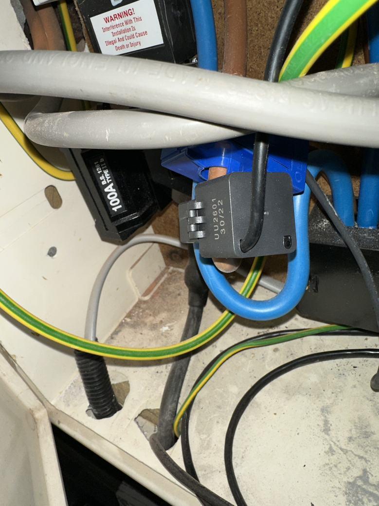
9 ELECTRIC METER
Photos
5 Photos (see photos page)
10
Photos
12
Ground
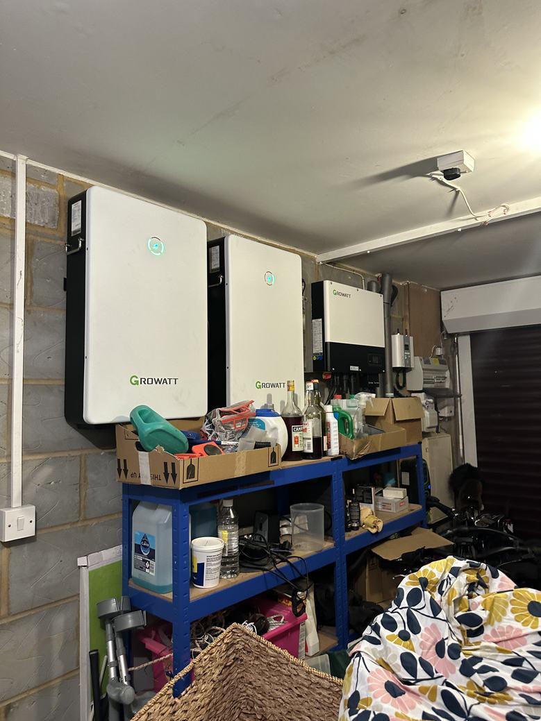
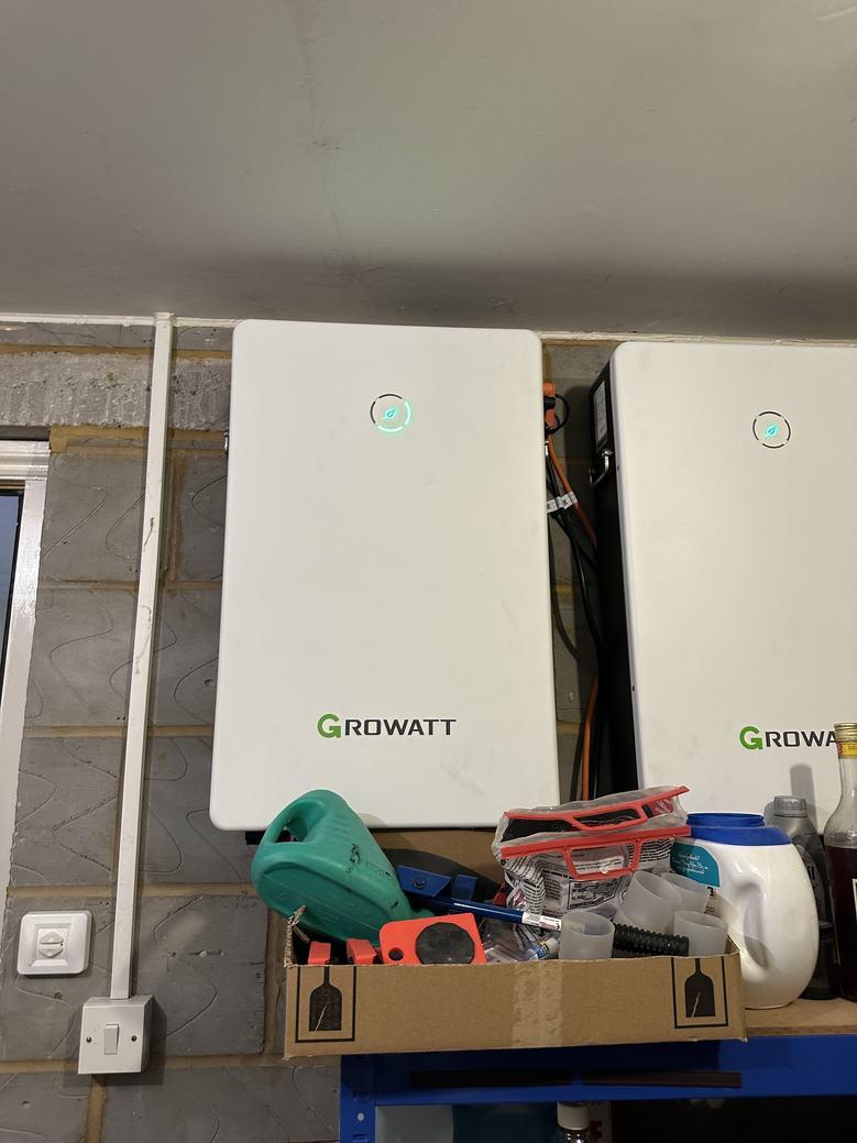
WIDTH: 2.52 m •LENGTH: 5.17 m • CEILING HEIGHT: 2.31 m AREA: 12.81 m² • PERIMETER: 15.02 m Party Wall 0.80 3.13 4.44 2.17 2.51 5.17 2.02 0.88 2.52 11 12 Solar PV Inverter & Batteries 10 9 8
Garage
Floor
SOLAR
& BATTERIES
PV INVERTER
4 Photos (see photos page)
GARAGE DOOR Dimensions 2.17 m x 2.13 m (Width x Height) Distance to Floor 0.00 m THIS FLOOR PLAN IS NOTTO SCALE AND IS FOR VISUAL REPRESENTATION ONLY. PLEASE NOTE, SOME MEASUREMENTS PRESENT MAY NOT BE ACTUAL MEASUREMENTS - REGENERTEC CONSULTING OBTAIN MEASUREMENTS FOR INTERNAL AND EXTERNAL WALLS FOR THE PURPOSES OF COMPLETING HEAT LOSS CALCULATIONS ONLY. ALL OTHER MEASUREMENTS ARE FOR GUIDANCE ONLY AND REGENERTEC CONSULTING ACCEPT NO LIABILITY FOR THE ACCURACY OF THESE MEASUREMENTS IF USED FOR ALTERNATIVE PURPOSES. Page 9/59
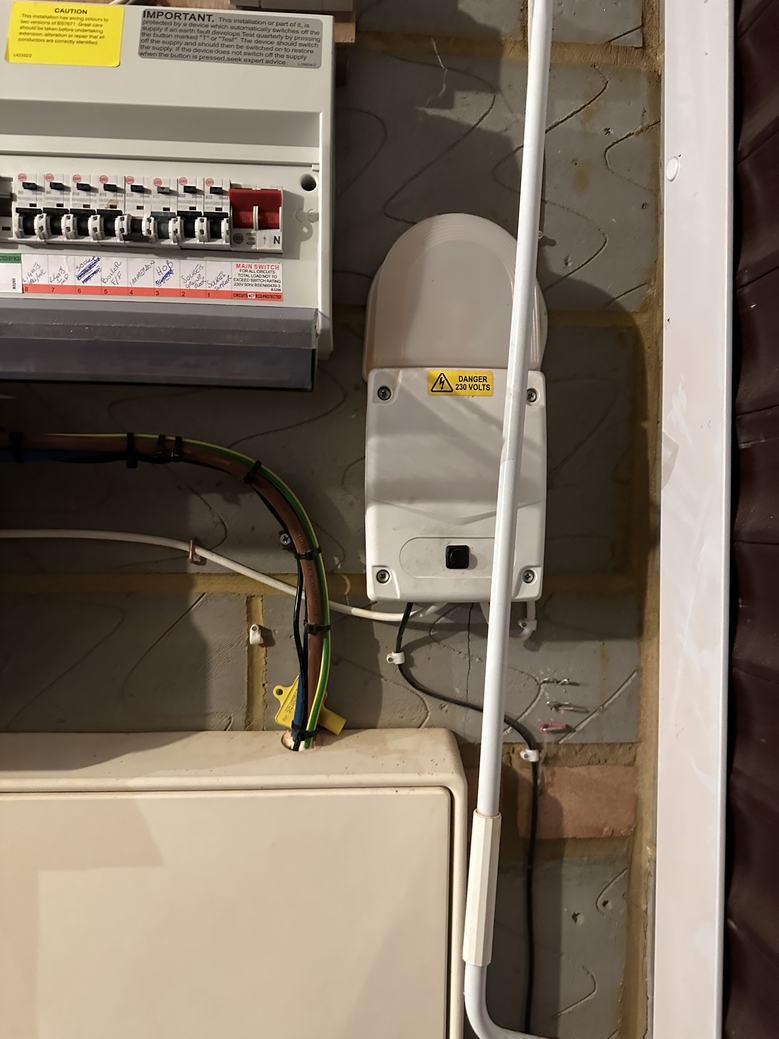
▼ Photos/Garage 8 Breaker Box Photo 1 8 Breaker Box Photo 2 8 Breaker Box Photo 3 8 Breaker Box Photo 4 8 Breaker Box Photo 5 8 Breaker Box Photo 6 THIS FLOOR PLAN IS NOTTO SCALE AND IS FOR VISUAL REPRESENTATION ONLY. PLEASE NOTE, SOME MEASUREMENTS PRESENT MAY NOT BE ACTUAL MEASUREMENTS - REGENERTEC CONSULTING OBTAIN MEASUREMENTS FOR INTERNAL AND EXTERNAL WALLS FOR THE PURPOSES OF COMPLETING HEAT LOSS CALCULATIONS ONLY. ALL OTHER MEASUREMENTS ARE FOR GUIDANCE ONLY AND REGENERTEC CONSULTING ACCEPT NO LIABILITY FOR THE ACCURACY OF THESE MEASUREMENTS IF USED FOR ALTERNATIVE PURPOSES. Page 10/59
▼ Photos/Garage 9 Electric Meter Photo 1 9 Electric Meter Photo 2 9 Electric Meter Photo 3 9 Electric Meter Photo 4 9 Electric Meter Photo 5 10 Solar PV Inverter & Batteries Photo 1 THIS FLOOR PLAN IS NOTTO SCALE AND IS FOR VISUAL REPRESENTATION ONLY. PLEASE NOTE, SOME MEASUREMENTS PRESENT MAY NOT BE ACTUAL MEASUREMENTS - REGENERTEC CONSULTING OBTAIN MEASUREMENTS FOR INTERNAL AND EXTERNAL WALLS FOR THE PURPOSES OF COMPLETING HEAT LOSS CALCULATIONS ONLY. ALL OTHER MEASUREMENTS ARE FOR GUIDANCE ONLY AND REGENERTEC CONSULTING ACCEPT NO LIABILITY FOR THE ACCURACY OF THESE MEASUREMENTS IF USED FOR ALTERNATIVE PURPOSES. Page 11/59
Photos/Garage
▼
Solar PV
& Batteries
2 10 Solar PV Inverter
3 10
4 THIS FLOOR PLAN IS NOTTO SCALE AND IS FOR VISUAL REPRESENTATION ONLY. PLEASE NOTE, SOME MEASUREMENTS PRESENT MAY NOT BE ACTUAL MEASUREMENTS - REGENERTEC CONSULTING OBTAIN MEASUREMENTS FOR INTERNAL AND EXTERNAL WALLS FOR THE PURPOSES OF COMPLETING HEAT LOSS CALCULATIONS ONLY. ALL OTHER MEASUREMENTS ARE FOR GUIDANCE ONLY AND REGENERTEC CONSULTING ACCEPT NO LIABILITY FOR THE ACCURACY OF THESE MEASUREMENTS IF USED FOR ALTERNATIVE PURPOSES. Page 12/59
10
Inverter
Photo
& Batteries
Photo
Solar PV
Inverter & Batteries Photo
▼ Hall Ground Floor WIDTH: 5.93 m •LENGTH: 6.00 m • CEILING HEIGHT: 2.31 m AREA: 17.74 m² • PERIMETER: 24.98 m Party Wall 2.04 0.80 3.29 0.690.801.15 0 91 0.99 0.80 1.00 2.00 0 80 1 18 3.40 0.90 2.10 2.07 0.80 3.42 0.98 2.09 1.78 5.93 6.00 17 22 21 13 14 16 18 19 20 23 15 Roof Lantern 780x570 ▼ Hall/Ground Floor 13 STAIRCASE Dimensions 1.50 m x 1.00 m x 2.00 m (Width x Depth x Height) 15 FRENCH WINDOW Dimensions 0.47 m x 1.18 m (Width x Height) Distance to Floor 1.00 m 16 HINGED DOOR Dimensions 0.90 m x 2.06 m (Width x Height) Distance to Floor 0.00 m 17 WATER RADIATOR Dimensions 1.10 m x 0.75 m (Width x Height) THIS FLOOR PLAN IS NOTTO SCALE AND IS FOR VISUAL REPRESENTATION ONLY. PLEASE NOTE, SOME MEASUREMENTS PRESENT MAY NOT BE ACTUAL MEASUREMENTS - REGENERTEC CONSULTING OBTAIN MEASUREMENTS FOR INTERNAL AND EXTERNAL WALLS FOR THE PURPOSES OF COMPLETING HEAT LOSS CALCULATIONS ONLY. ALL OTHER MEASUREMENTS ARE FOR GUIDANCE ONLY AND REGENERTEC CONSULTING ACCEPT NO LIABILITY FOR THE ACCURACY OF THESE MEASUREMENTS IF USED FOR ALTERNATIVE PURPOSES. Page 13/59
▼ Hall/Ground Floor
WATER RADIATOR Distance to Floor 0.00 m
2 Photos (see photos page) Radiator Information Radiator Type 11 Height 750 Width 1100 18 HINGED DOOR Dimensions 0.80 m x 2.04 m (Width x Height) Distance to Floor 0.00 m 19 HINGED DOOR Dimensions 0.80 m x 2.04 m (Width x Height) Distance to Floor 0.00 m 20 HINGED DOOR Dimensions 0.80 m x 2.04 m (Width x Height) Distance to Floor 0.00 m 21 THERMOSTAT Circuit Number Dimensions 0.20 m x 0.30 m (Width x Height) Distance to Floor 1.10 m
1 Photo (see photos page) THIS FLOOR PLAN IS NOTTO SCALE AND IS FOR VISUAL REPRESENTATION ONLY. PLEASE NOTE, SOME MEASUREMENTS PRESENT MAY NOT BE ACTUAL MEASUREMENTS - REGENERTEC CONSULTING OBTAIN MEASUREMENTS FOR INTERNAL AND EXTERNAL WALLS FOR THE PURPOSES OF COMPLETING HEAT LOSS CALCULATIONS ONLY. ALL OTHER MEASUREMENTS ARE FOR GUIDANCE ONLY AND REGENERTEC CONSULTING ACCEPT NO LIABILITY FOR THE ACCURACY OF THESE MEASUREMENTS IF USED FOR ALTERNATIVE PURPOSES. Page 14/59
17
Photos
Photo
▼ Hall/Ground Floor
22 WATER RADIATOR
Dimensions 0.60 m x 0.60 m (Width x Height)
Distance to Floor 0.00 m
Photos
3 Photos (see photos page)
Radiator Information
Radiator Type 11
Height 600
Width 600
THIS FLOOR PLAN IS NOTTO SCALE AND IS FOR VISUAL REPRESENTATION ONLY. PLEASE NOTE, SOME MEASUREMENTS PRESENT MAY NOT BE ACTUAL MEASUREMENTS - REGENERTEC CONSULTING OBTAIN MEASUREMENTS FOR INTERNAL AND EXTERNAL WALLS FOR THE PURPOSES OF COMPLETING HEAT LOSS CALCULATIONS ONLY. ALL OTHER MEASUREMENTS ARE FOR GUIDANCE ONLY AND REGENERTEC CONSULTING ACCEPT NO LIABILITY FOR THE ACCURACY OF THESE MEASUREMENTS IF USED FOR ALTERNATIVE PURPOSES. Page 15/59
Photos/Hall 17 Water Radiator Photo 1 17 Water Radiator Photo 2 21 Thermostat 22 Water Radiator Photo 1 22 Water Radiator Photo 2 22 Water Radiator Photo 3 THIS FLOOR PLAN IS NOTTO SCALE AND IS FOR VISUAL REPRESENTATION ONLY. PLEASE NOTE, SOME MEASUREMENTS PRESENT MAY NOT BE ACTUAL MEASUREMENTS - REGENERTEC CONSULTING OBTAIN MEASUREMENTS FOR INTERNAL AND EXTERNAL WALLS FOR THE PURPOSES OF COMPLETING HEAT LOSS CALCULATIONS ONLY. ALL OTHER MEASUREMENTS ARE FOR GUIDANCE ONLY AND REGENERTEC CONSULTING ACCEPT NO LIABILITY FOR THE ACCURACY OF THESE MEASUREMENTS IF USED FOR ALTERNATIVE PURPOSES. Page 16/59
▼
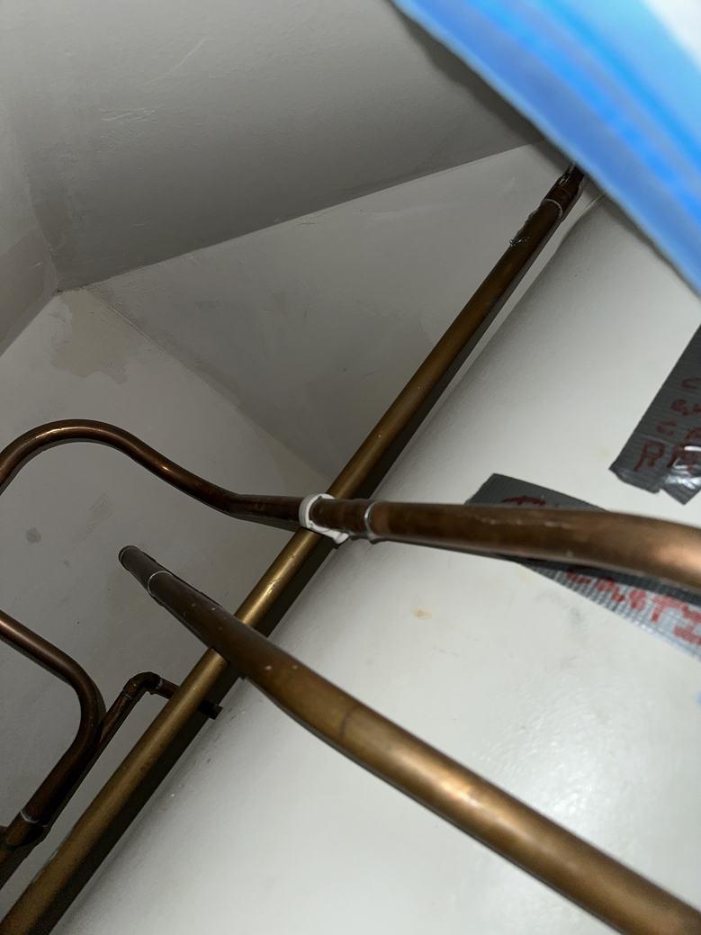
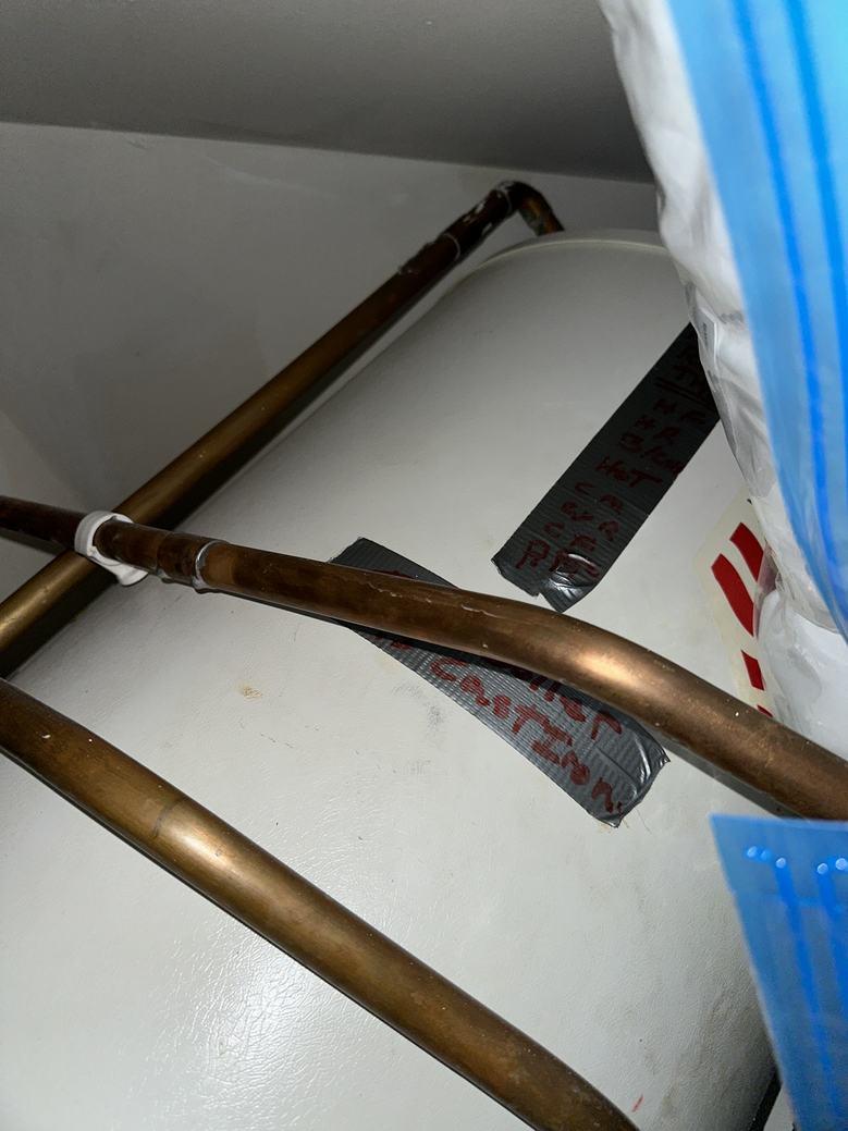
24 UFH
Photos
4 Photos (see photos page)
Cupboard Ground Floor WIDTH: 1.39 m •LENGTH: 1.47 m • CEILING HEIGHT: 2.31 m AREA: 1.77 m² • PERIMETER: 5.29 m Party Wall 0.73 1.060.80 0.64 1.39 1.47 25 UFH Manifold24
Cupboard /Ground Floor
▼
▼
MANIFOLD
THIS FLOOR PLAN IS NOTTO SCALE AND IS FOR VISUAL REPRESENTATION ONLY. PLEASE NOTE, SOME MEASUREMENTS PRESENT MAY NOT BE ACTUAL MEASUREMENTS - REGENERTEC CONSULTING OBTAIN MEASUREMENTS FOR INTERNAL AND EXTERNAL WALLS FOR THE PURPOSES OF COMPLETING HEAT LOSS CALCULATIONS ONLY. ALL OTHER MEASUREMENTS ARE FOR GUIDANCE ONLY AND REGENERTEC CONSULTING ACCEPT NO LIABILITY FOR THE ACCURACY OF THESE MEASUREMENTS IF USED FOR ALTERNATIVE PURPOSES. Page 17/59
24 UFH Manifold Photo 1 24 UFH Manifold Photo 2 24 UFH Manifold Photo 3 24 UFH Manifold Photo 4 THIS FLOOR PLAN IS NOTTO SCALE AND IS FOR VISUAL REPRESENTATION ONLY. PLEASE NOTE, SOME MEASUREMENTS PRESENT MAY NOT BE ACTUAL MEASUREMENTS - REGENERTEC CONSULTING OBTAIN MEASUREMENTS FOR INTERNAL AND EXTERNAL WALLS FOR THE PURPOSES OF COMPLETING HEAT LOSS CALCULATIONS ONLY. ALL OTHER MEASUREMENTS ARE FOR GUIDANCE ONLY AND REGENERTEC CONSULTING ACCEPT NO LIABILITY FOR THE ACCURACY OF THESE MEASUREMENTS IF USED FOR ALTERNATIVE PURPOSES. Page 18/59
▼ Photos/Cupboard
▼
Photos
3 Photos (see photos page)
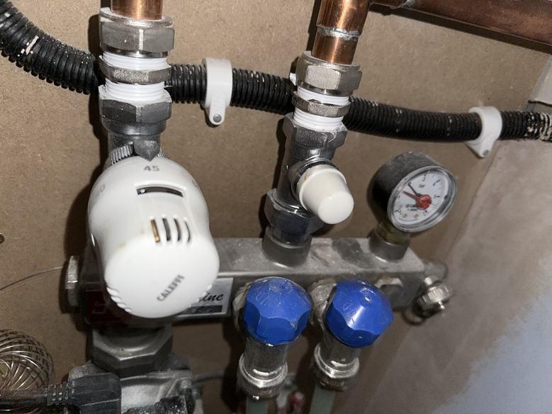
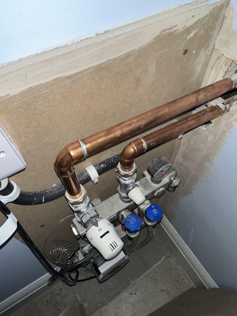
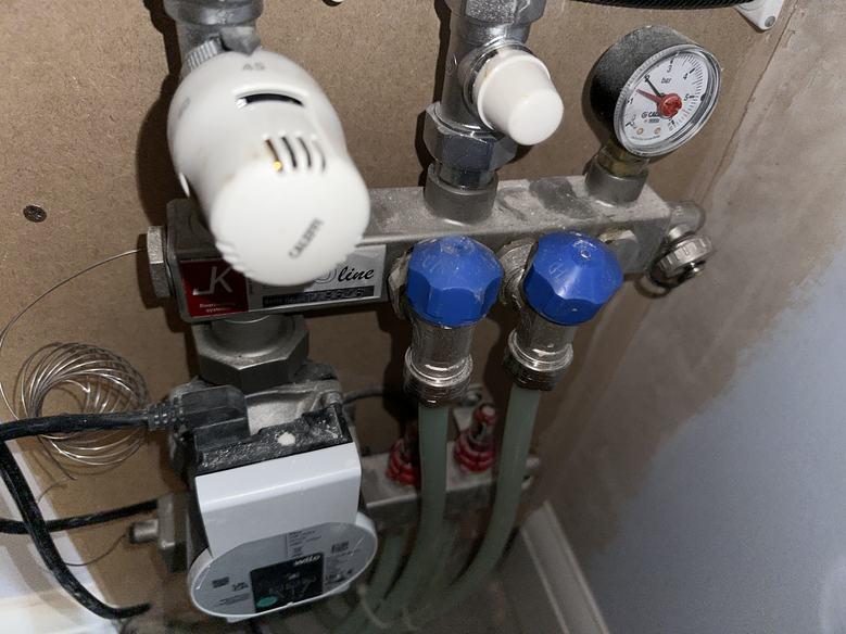
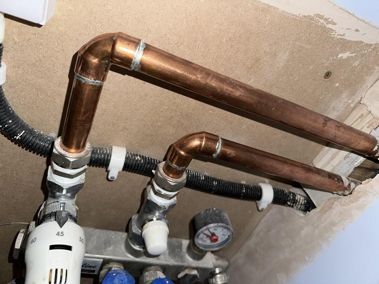
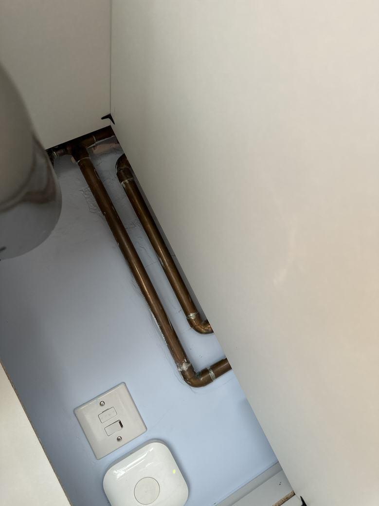
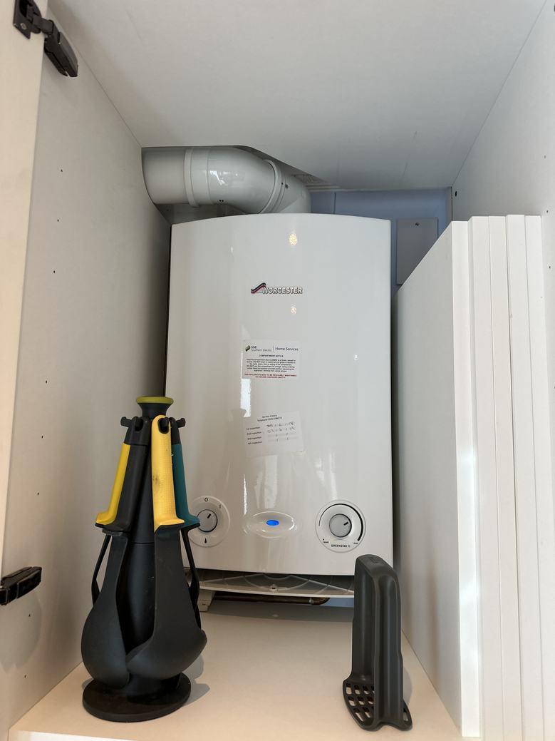
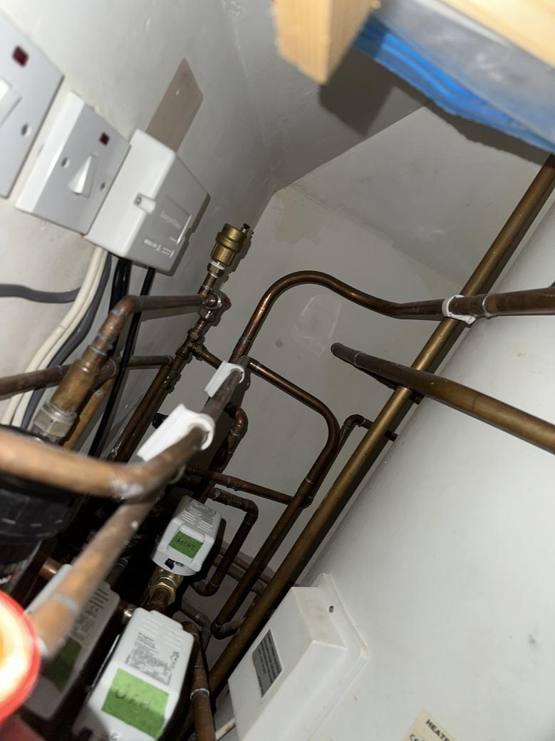
Boiler
Kitchen / Dining Room Ground Floor WIDTH: 4.91 m •LENGTH: 7.35 m • CEILING HEIGHT: 2.31 m AREA: 27.58 m² • PERIMETER: 24.52 m Party Wall 2.48 2.48 1.70 1.09 3.50 0.69 0.88 0.86 2.43 3.85 1.99 0.80 2.12 4.91 7.35 7.35 32 26 30 33 27 28 29 31
▼
Kitchen / Dining Room /Ground Floor
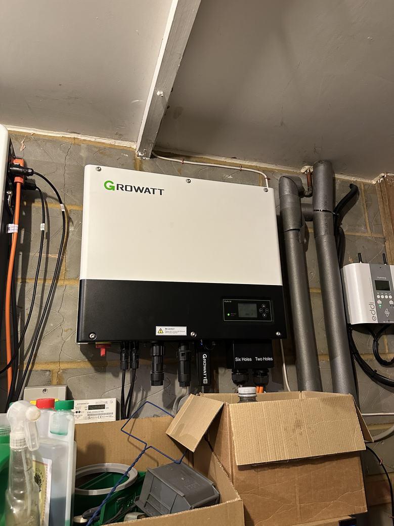
GAS FURNACE Dimensions 0.42 m x 0.55 m x 1.86 m (Width x Depth x Height)
26
Information Boiler Type 27 FRENCH WINDOW Dimensions 2.48 m x 1.33 m (Width x Height) Distance to Floor 1.00 m 28 FRENCH WINDOW Dimensions 0.58 m x 1.33 m (Width x Height) THIS FLOOR PLAN IS NOTTO SCALE AND IS FOR VISUAL REPRESENTATION ONLY. PLEASE NOTE, SOME MEASUREMENTS PRESENT MAY NOT BE ACTUAL MEASUREMENTS - REGENERTEC CONSULTING OBTAIN MEASUREMENTS FOR INTERNAL AND EXTERNAL WALLS FOR THE PURPOSES OF COMPLETING HEAT LOSS CALCULATIONS ONLY. ALL OTHER MEASUREMENTS ARE FOR GUIDANCE ONLY AND REGENERTEC CONSULTING ACCEPT NO LIABILITY FOR THE ACCURACY OF THESE MEASUREMENTS IF USED FOR ALTERNATIVE PURPOSES. Page 19/59
▼ Kitchen / Dining Room /Ground Floor
28 FRENCH WINDOW
Distance to Floor 1.00 m
29 FRENCH WINDOW
Dimensions
1.70 m x 1.33 m (Width x Height)
Distance to Floor 1.00 m
30 HINGED DOOR
Dimensions 1.09 m x 2.04 m (Width x Height)
Distance to Floor 0.00 m
31 FRENCH WINDOW
Dimensions
0.88 m x 2.07 m (Width x Height)
Distance to Floor 1.00 m
32 THERMOSTAT
Circuit Number
Dimensions
0.20 m x 0.30 m (Width x Height)
Distance to Floor 1.10 m
Photo
1 Photo (see photos page)
THIS FLOOR PLAN IS NOTTO SCALE AND IS FOR VISUAL REPRESENTATION ONLY. PLEASE NOTE, SOME MEASUREMENTS PRESENT MAY NOT BE ACTUAL MEASUREMENTS - REGENERTEC CONSULTING OBTAIN MEASUREMENTS FOR INTERNAL AND EXTERNAL WALLS FOR THE PURPOSES OF COMPLETING HEAT LOSS CALCULATIONS ONLY. ALL OTHER MEASUREMENTS ARE FOR GUIDANCE ONLY AND REGENERTEC CONSULTING ACCEPT NO LIABILITY FOR THE ACCURACY OF THESE MEASUREMENTS IF USED FOR ALTERNATIVE PURPOSES. Page 20/59

▼ Photos/Kitchen / Dining Room 26 Gas Furnace Photo 1 26 Gas Furnace Photo 2 26 Gas Furnace Photo 3 32 Thermostat THIS FLOOR PLAN IS NOTTO SCALE AND IS FOR VISUAL REPRESENTATION ONLY. PLEASE NOTE, SOME MEASUREMENTS PRESENT MAY NOT BE ACTUAL MEASUREMENTS - REGENERTEC CONSULTING OBTAIN MEASUREMENTS FOR INTERNAL AND EXTERNAL WALLS FOR THE PURPOSES OF COMPLETING HEAT LOSS CALCULATIONS ONLY. ALL OTHER MEASUREMENTS ARE FOR GUIDANCE ONLY AND REGENERTEC CONSULTING ACCEPT NO LIABILITY FOR THE ACCURACY OF THESE MEASUREMENTS IF USED FOR ALTERNATIVE PURPOSES. Page 21/59
▼ Shower Room/Ground Floor
35 FRENCH WINDOW
Dimensions 0.43 m x 0.99 m (Width x Height)
Distance to Floor 1.00 m
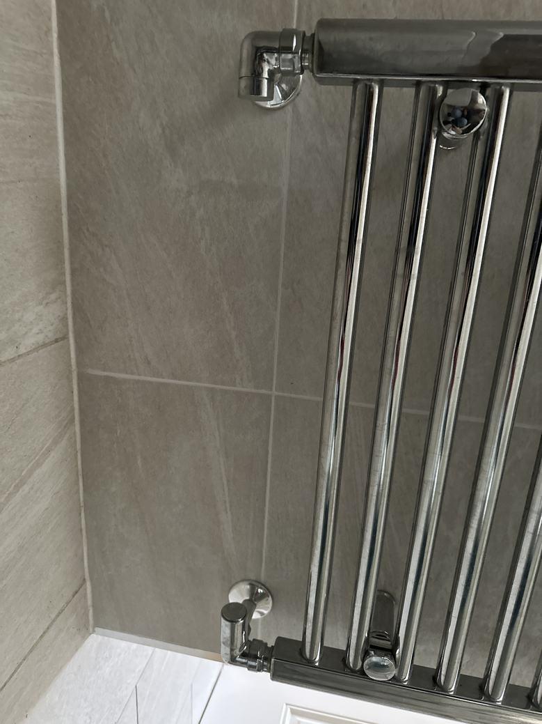
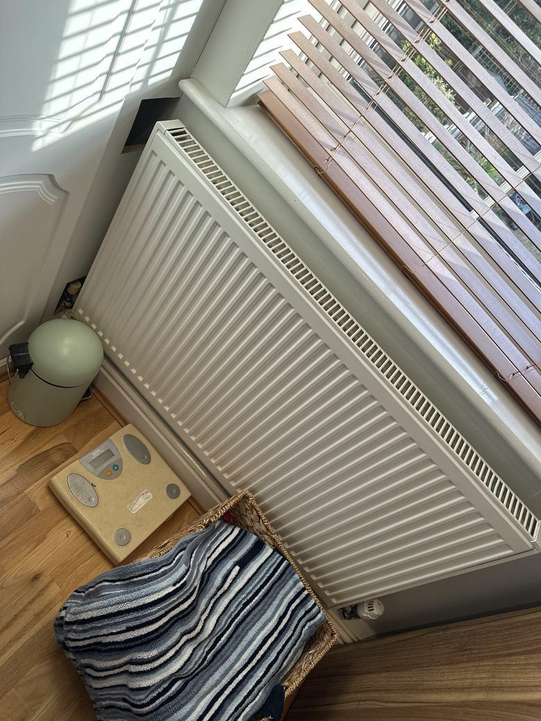
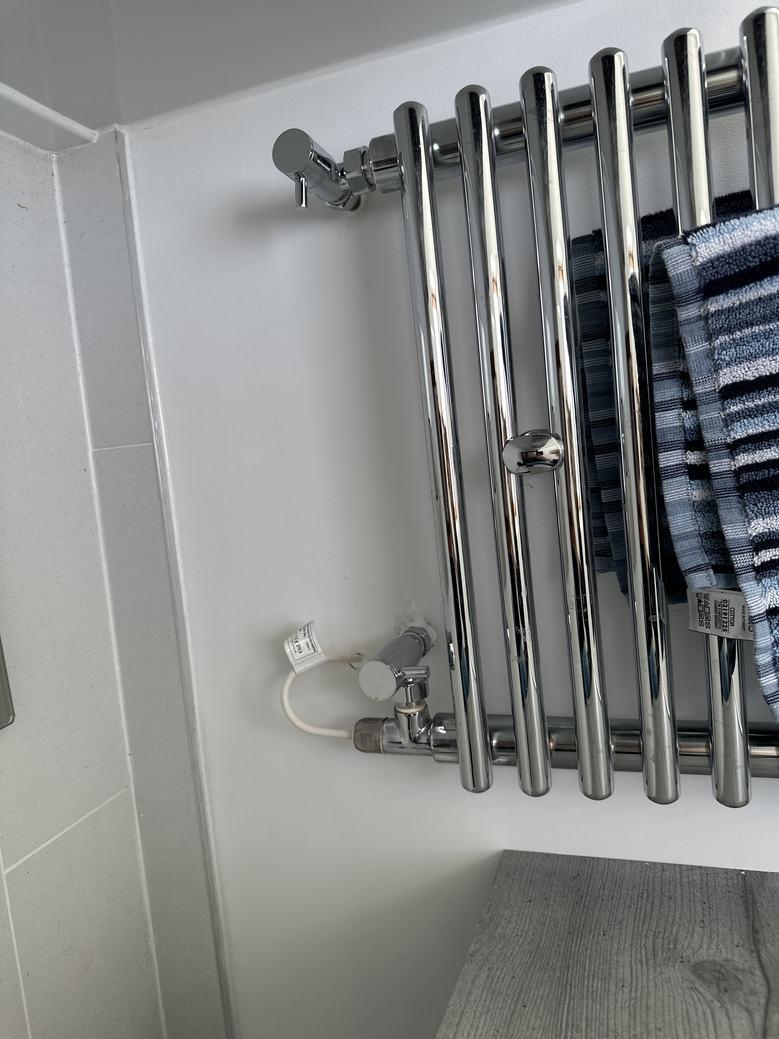
36 TOWEL RADIATOR
Dimensions 0.60 m x 1.80 m (Width x Height)
Distance to Floor 0.30 m
Photos
2 Photos (see photos page)
Towel Rail Information
Towel Rail Type Wet Central Heating
1800
WIDTH: 2.23 m •LENGTH: 2.37 m • CEILING HEIGHT: 2.31 m AREA: 4.32 m² • PERIMETER: 9.20 m Party Wall 2.23 1.04 1.66 1.36 0.71 0.80 0.87 2.37 2.23 36 34 35
▼ Shower Room Ground Floor
Height
THIS FLOOR PLAN IS NOTTO SCALE AND IS FOR VISUAL REPRESENTATION ONLY. PLEASE NOTE, SOME MEASUREMENTS PRESENT MAY NOT BE ACTUAL MEASUREMENTS - REGENERTEC CONSULTING OBTAIN MEASUREMENTS FOR INTERNAL AND EXTERNAL WALLS FOR THE PURPOSES OF COMPLETING HEAT LOSS CALCULATIONS ONLY. ALL OTHER MEASUREMENTS ARE FOR GUIDANCE ONLY AND REGENERTEC CONSULTING ACCEPT NO LIABILITY FOR THE ACCURACY OF THESE MEASUREMENTS IF USED FOR ALTERNATIVE PURPOSES. Page 22/59
▼ Shower Room/Ground Floor
36 TOWEL RADIATOR Width 600 THIS FLOOR PLAN IS NOTTO SCALE AND IS FOR VISUAL REPRESENTATION ONLY. PLEASE NOTE, SOME MEASUREMENTS PRESENT MAY NOT BE ACTUAL MEASUREMENTS - REGENERTEC CONSULTING OBTAIN MEASUREMENTS FOR INTERNAL AND EXTERNAL WALLS FOR THE PURPOSES OF COMPLETING HEAT LOSS CALCULATIONS ONLY. ALL OTHER MEASUREMENTS ARE FOR GUIDANCE ONLY AND REGENERTEC CONSULTING ACCEPT NO LIABILITY FOR THE ACCURACY OF THESE MEASUREMENTS IF USED FOR ALTERNATIVE PURPOSES. Page 23/59
▼ Photos/Shower Room
1
36 Towel Radiator Photo
THIS FLOOR PLAN IS NOTTO SCALE AND IS FOR VISUAL REPRESENTATION ONLY. PLEASE NOTE, SOME MEASUREMENTS PRESENT MAY NOT BE ACTUAL MEASUREMENTS - REGENERTEC CONSULTING OBTAIN MEASUREMENTS FOR INTERNAL AND EXTERNAL WALLS FOR THE PURPOSES OF COMPLETING HEAT LOSS CALCULATIONS ONLY. ALL OTHER MEASUREMENTS ARE FOR GUIDANCE ONLY AND REGENERTEC CONSULTING ACCEPT NO LIABILITY FOR THE ACCURACY OF THESE MEASUREMENTS IF USED FOR ALTERNATIVE PURPOSES. Page 24/59
36 Towel Radiator Photo 2
▼
▼ Sitting Room/Ground Floor
Sitting
Ground
WIDTH: 3.40 m •LENGTH: 4.31 m • CEILING HEIGHT: 2.31 m AREA: 13.26 m² • PERIMETER: 15.42 m Party Wall 1.35 0.62 3.40 3.73 2.39 0.80 1.01 4.31 37 38 41 39 40
Room
Floor
WATER RADIATOR Dimensions 0.80 m x 0.60 m (Width x Height)
to Floor 0.00 m
2 Photos (see photos page) Radiator Information Radiator Type 22 Height 600 Width 800 38 HINGED DOOR Dimensions 0.80 m x 2.04 m (Width x Height) THIS FLOOR PLAN IS NOTTO SCALE AND IS FOR VISUAL REPRESENTATION ONLY. PLEASE NOTE, SOME MEASUREMENTS PRESENT MAY NOT BE ACTUAL MEASUREMENTS - REGENERTEC CONSULTING OBTAIN MEASUREMENTS FOR INTERNAL AND EXTERNAL WALLS FOR THE PURPOSES OF COMPLETING HEAT LOSS CALCULATIONS ONLY. ALL OTHER MEASUREMENTS ARE FOR GUIDANCE ONLY AND REGENERTEC CONSULTING ACCEPT NO LIABILITY FOR THE ACCURACY OF THESE MEASUREMENTS IF USED FOR ALTERNATIVE PURPOSES. Page 25/59
37
Distance
Photos
▼ Sitting Room/Ground Floor
38 HINGED DOOR
Distance to Floor 0.00 m
39 FRENCH WINDOW
Dimensions 0.46 m x 1.01 m (Width x Height)
Distance to Floor 1.00 m
40 FRENCH WINDOW
Dimensions 0.46 m x 1.01 m (Width x Height)
Distance to Floor 1.00 m
41 FRENCH DOOR
Dimensions 1.35 m x 2.05 m (Width x Height)
Distance to Floor 0.00 m
THIS FLOOR PLAN IS NOTTO SCALE AND IS FOR VISUAL REPRESENTATION ONLY. PLEASE NOTE, SOME MEASUREMENTS PRESENT MAY NOT BE ACTUAL MEASUREMENTS - REGENERTEC CONSULTING OBTAIN MEASUREMENTS FOR INTERNAL AND EXTERNAL WALLS FOR THE PURPOSES OF COMPLETING HEAT LOSS CALCULATIONS ONLY. ALL OTHER MEASUREMENTS ARE FOR GUIDANCE ONLY AND REGENERTEC CONSULTING ACCEPT NO LIABILITY FOR THE ACCURACY OF THESE MEASUREMENTS IF USED FOR ALTERNATIVE PURPOSES. Page 26/59
/Sitting
37 Water Radiator Photo 1 37 Water Radiator Photo 2 THIS FLOOR PLAN IS NOTTO SCALE AND IS FOR VISUAL REPRESENTATION ONLY. PLEASE NOTE, SOME MEASUREMENTS PRESENT MAY NOT BE ACTUAL MEASUREMENTS - REGENERTEC CONSULTING OBTAIN MEASUREMENTS FOR INTERNAL AND EXTERNAL WALLS FOR THE PURPOSES OF COMPLETING HEAT LOSS CALCULATIONS ONLY. ALL OTHER MEASUREMENTS ARE FOR GUIDANCE ONLY AND REGENERTEC CONSULTING ACCEPT NO LIABILITY FOR THE ACCURACY OF THESE MEASUREMENTS IF USED FOR ALTERNATIVE PURPOSES. Page 27/59
▼ Photos
Room
▼ 1st Floor TOTAL AREA: 49.94 m² •LIVING AREA: 49.94 m² • 57 58 59 55 56 53 51 45 46 43 44 49 50 48 Party Wall 42 3.96 0.91 0.88 2.28 1.23 0.63 1.75 2.63 5.19 1.79 0.67 0.90 1.43 0.90 1.00 4.90 2.66 3.84 1.26 0.87 0.85 2.98 Living Room 22.68 m² (4.91 × 5.19) Landing 5.39 m² 3.01 × 1.79 Bedroom 1 16.80 m² (4.90 × 3.84) En-suite 5.10 m² 1.77 × 2.98 THIS FLOOR PLAN IS NOTTO SCALE AND IS FOR VISUAL REPRESENTATION ONLY. PLEASE NOTE, SOME MEASUREMENTS PRESENT MAY NOT BE ACTUAL MEASUREMENTS - REGENERTEC CONSULTING OBTAIN MEASUREMENTS FOR INTERNAL AND EXTERNAL WALLS FOR THE PURPOSES OF COMPLETING HEAT LOSS CALCULATIONS ONLY. ALL OTHER MEASUREMENTS ARE FOR GUIDANCE ONLY AND REGENERTEC CONSULTING ACCEPT NO LIABILITY FOR THE ACCURACY OF THESE MEASUREMENTS IF USED FOR ALTERNATIVE PURPOSES. Page 28/59
▼ 1st Floor
42 HEAT PUMP
Dimensions
0.80 m x 0.80 m x 0.40 m (Width x Depth x Height)
Photos
3 Photos (see photos page)
THIS FLOOR PLAN IS NOTTO SCALE AND IS FOR VISUAL REPRESENTATION ONLY. PLEASE NOTE, SOME MEASUREMENTS PRESENT MAY NOT BE ACTUAL MEASUREMENTS - REGENERTEC CONSULTING OBTAIN MEASUREMENTS FOR INTERNAL AND EXTERNAL WALLS FOR THE PURPOSES OF COMPLETING HEAT LOSS CALCULATIONS ONLY. ALL OTHER MEASUREMENTS ARE FOR GUIDANCE ONLY AND REGENERTEC CONSULTING ACCEPT NO LIABILITY FOR THE ACCURACY OF THESE MEASUREMENTS IF USED FOR ALTERNATIVE PURPOSES. Page 29/59
▼ Photos/1st Floor 42 Heat Pump Photo 1 42 Heat Pump Photo 2 42 Heat Pump Photo 3 THIS FLOOR PLAN IS NOTTO SCALE AND IS FOR VISUAL REPRESENTATION ONLY. PLEASE NOTE, SOME MEASUREMENTS PRESENT MAY NOT BE ACTUAL MEASUREMENTS - REGENERTEC CONSULTING OBTAIN MEASUREMENTS FOR INTERNAL AND EXTERNAL WALLS FOR THE PURPOSES OF COMPLETING HEAT LOSS CALCULATIONS ONLY. ALL OTHER MEASUREMENTS ARE FOR GUIDANCE ONLY AND REGENERTEC CONSULTING ACCEPT NO LIABILITY FOR THE ACCURACY OF THESE MEASUREMENTS IF USED FOR ALTERNATIVE PURPOSES. Page 30/59
43
Photos
Bedroom 1 1st Floor WIDTH: 4.90 m •LENGTH: 3.84 m • CEILING HEIGHT: 2.30 m AREA: 16.80 m² • PERIMETER: 17.09 m Party Wall 0.67 0.90 1.43 0.90 1.00 4.90 2.66 1.18 0.790.93 0.80 2.03 3.02 3.84 45 46 47 43 44
Bedroom 1/1st Floor
▼
▼
FRENCH WINDOW
0.90 m x 1.18 m (Width x Height) Distance to Floor 1.00 m
FRENCH WINDOW
0.90 m x 1.18 m (Width x Height) Distance to Floor 1.00 m
WATER RADIATOR Dimensions 1.00 m x 0.60 m (Width x Height)
to Floor 0.00 m
Dimensions
44
Dimensions
45
Distance
3
(see photos page) THIS FLOOR PLAN IS NOTTO SCALE AND IS FOR VISUAL REPRESENTATION ONLY. PLEASE NOTE, SOME MEASUREMENTS PRESENT MAY NOT BE ACTUAL MEASUREMENTS - REGENERTEC CONSULTING OBTAIN MEASUREMENTS FOR INTERNAL AND EXTERNAL WALLS FOR THE PURPOSES OF COMPLETING HEAT LOSS CALCULATIONS ONLY. ALL OTHER MEASUREMENTS ARE FOR GUIDANCE ONLY AND REGENERTEC CONSULTING ACCEPT NO LIABILITY FOR THE ACCURACY OF THESE MEASUREMENTS IF USED FOR ALTERNATIVE PURPOSES. Page 31/59
Photos
▼ Bedroom 1/1st Floor
45 WATER RADIATOR Radiator Information Radiator Type 11 Height 600 Width 1000 46 HINGED DOOR Dimensions 0.80 m x 2.04 m (Width x Height) Distance to Floor 0.00 m THIS FLOOR PLAN IS NOTTO SCALE AND IS FOR VISUAL REPRESENTATION ONLY. PLEASE NOTE, SOME MEASUREMENTS PRESENT MAY NOT BE ACTUAL MEASUREMENTS - REGENERTEC CONSULTING OBTAIN MEASUREMENTS FOR INTERNAL AND EXTERNAL WALLS FOR THE PURPOSES OF COMPLETING HEAT LOSS CALCULATIONS ONLY. ALL OTHER MEASUREMENTS ARE FOR GUIDANCE ONLY AND REGENERTEC CONSULTING ACCEPT NO LIABILITY FOR THE ACCURACY OF THESE MEASUREMENTS IF USED FOR ALTERNATIVE PURPOSES. Page 32/59
▼ Photos/Bedroom 1 45 Water Radiator Photo 1 45 Water Radiator Photo 2 45 Water Radiator Photo 3 THIS FLOOR PLAN IS NOTTO SCALE AND IS FOR VISUAL REPRESENTATION ONLY. PLEASE NOTE, SOME MEASUREMENTS PRESENT MAY NOT BE ACTUAL MEASUREMENTS - REGENERTEC CONSULTING OBTAIN MEASUREMENTS FOR INTERNAL AND EXTERNAL WALLS FOR THE PURPOSES OF COMPLETING HEAT LOSS CALCULATIONS ONLY. ALL OTHER MEASUREMENTS ARE FOR GUIDANCE ONLY AND REGENERTEC CONSULTING ACCEPT NO LIABILITY FOR THE ACCURACY OF THESE MEASUREMENTS IF USED FOR ALTERNATIVE PURPOSES. Page 33/59
▼
▼
49
Dimensions
x
Dimensions 0.60 m x 1.70 m (Width x Height)
Distance to Floor 0.30 m
Photos 2 Photos (see photos page)
Towel Rail Information
Towel Rail Type
Other
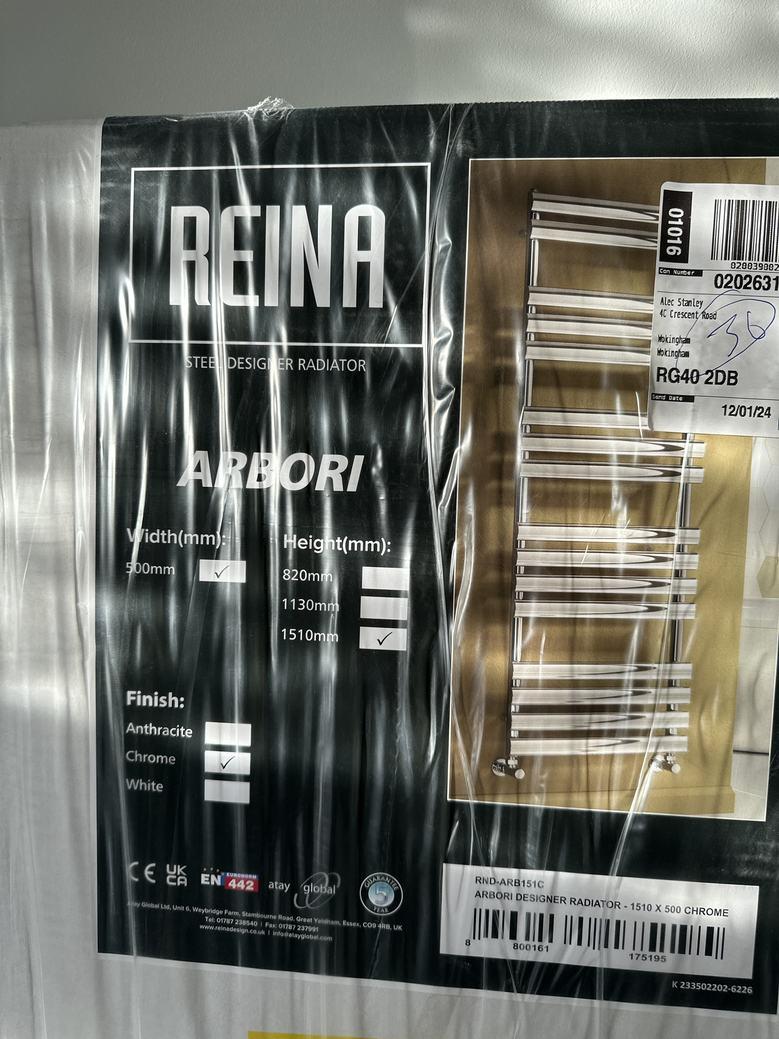
Details Reina Arbori
En-suite 1st Floor WIDTH: 1.77 m •LENGTH: 2.98 m • CEILING HEIGHT: 2.30 m AREA: 5.10 m² • PERIMETER: 9.16 m Party Wall 1.77 2.39 0.840.79 1.11 1.26 0.87 0.85 2.98 1.77 49 50 48
En-suite /1st Floor
48 FRENCH WINDOW
0.87 m
1.16 m (Width x Height)
Floor
m
Distance to
1.00
TOWEL
RADIATOR
THIS FLOOR PLAN IS NOTTO SCALE AND IS FOR VISUAL REPRESENTATION ONLY. PLEASE NOTE, SOME MEASUREMENTS PRESENT MAY NOT BE ACTUAL MEASUREMENTS - REGENERTEC CONSULTING OBTAIN MEASUREMENTS FOR INTERNAL AND EXTERNAL WALLS FOR THE PURPOSES OF COMPLETING HEAT LOSS CALCULATIONS ONLY. ALL OTHER MEASUREMENTS ARE FOR GUIDANCE ONLY AND REGENERTEC CONSULTING ACCEPT NO LIABILITY FOR THE ACCURACY OF THESE MEASUREMENTS IF USED FOR ALTERNATIVE PURPOSES. Page 34/59
'Other'
▼ En-suite /1st Floor
49 TOWEL
Height
Dimensions 0.79 m x 2.04 m (Width x Height)
Distance to Floor 0.00 m
RADIATOR
1510
Width 500
50 HINGED DOOR
THIS FLOOR PLAN IS NOTTO SCALE AND IS FOR VISUAL REPRESENTATION ONLY. PLEASE NOTE, SOME MEASUREMENTS PRESENT MAY NOT BE ACTUAL MEASUREMENTS - REGENERTEC CONSULTING OBTAIN MEASUREMENTS FOR INTERNAL AND EXTERNAL WALLS FOR THE PURPOSES OF COMPLETING HEAT LOSS CALCULATIONS ONLY. ALL OTHER MEASUREMENTS ARE FOR GUIDANCE ONLY AND REGENERTEC CONSULTING ACCEPT NO LIABILITY FOR THE ACCURACY OF THESE MEASUREMENTS IF USED FOR ALTERNATIVE PURPOSES. Page 35/59
▼ Photos/En-suite
1
49 Towel Radiator Photo
THIS FLOOR PLAN IS NOTTO SCALE AND IS FOR VISUAL REPRESENTATION ONLY. PLEASE NOTE, SOME MEASUREMENTS PRESENT MAY NOT BE ACTUAL MEASUREMENTS - REGENERTEC CONSULTING OBTAIN MEASUREMENTS FOR INTERNAL AND EXTERNAL WALLS FOR THE PURPOSES OF COMPLETING HEAT LOSS CALCULATIONS ONLY. ALL OTHER MEASUREMENTS ARE FOR GUIDANCE ONLY AND REGENERTEC CONSULTING ACCEPT NO LIABILITY FOR THE ACCURACY OF THESE MEASUREMENTS IF USED FOR ALTERNATIVE PURPOSES. Page 36/59
49 Towel Radiator Photo 2
Landing 1st Floor WIDTH: 3.01 m •LENGTH: 1.79 m • CEILING HEIGHT: 2.30 m AREA: 5.39 m² • PERIMETER: 9.60 m Party Wall 2.02 0.80 3.01 1.79 0.80 2.05 3.01 1.79 53 51 52 54
▼
Landing
▼
/1st Floor
m
2.00 m
51 U-SHAPED STAIRCASE Dimensions 1.79 m x 1.46
x
(Width x Depth x Height)
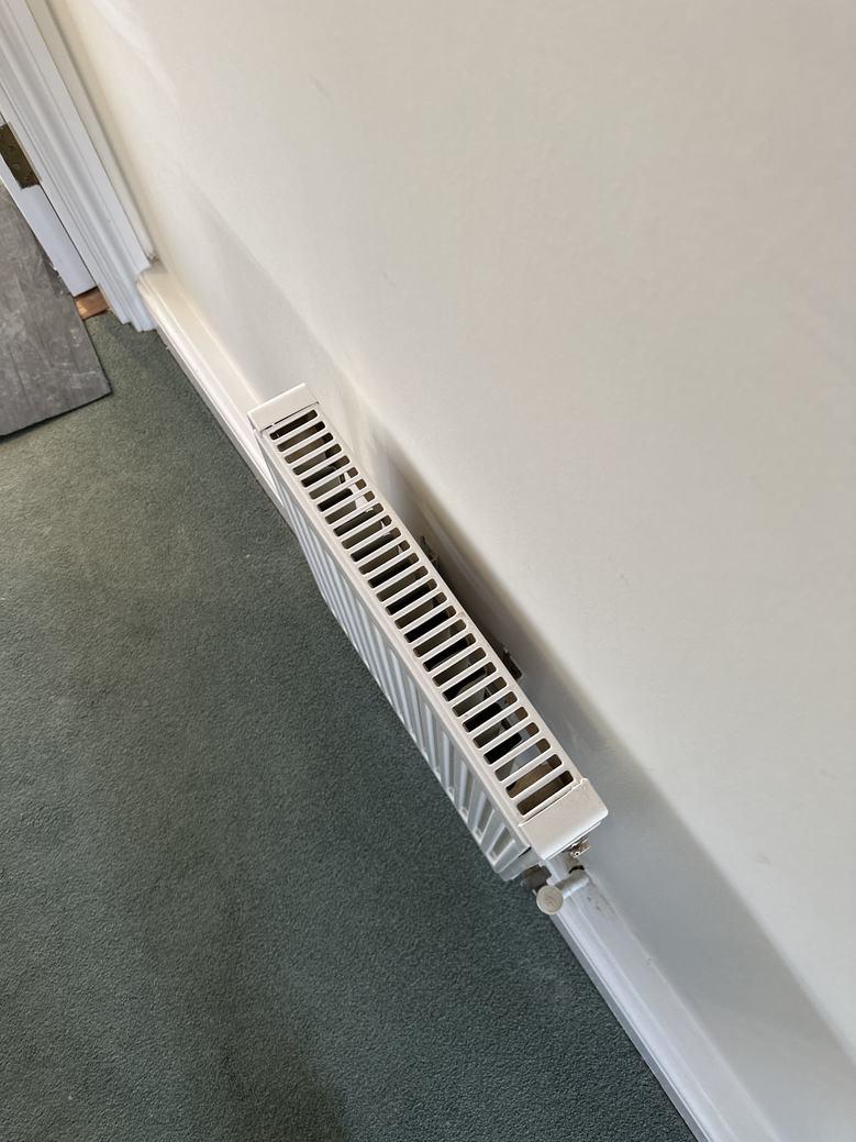
RADIATOR
0.40
m
Floor
53 WATER
Dimensions
m x 0.40
(Width x Height) Distance to
0.00 m
Photos 2 Photos (see photos page)
Radiator
Height
Width 400 THIS FLOOR PLAN IS NOTTO SCALE AND IS FOR VISUAL REPRESENTATION ONLY. PLEASE NOTE, SOME MEASUREMENTS PRESENT MAY NOT BE ACTUAL MEASUREMENTS - REGENERTEC CONSULTING OBTAIN MEASUREMENTS FOR INTERNAL AND EXTERNAL WALLS FOR THE PURPOSES OF COMPLETING HEAT LOSS CALCULATIONS ONLY. ALL OTHER MEASUREMENTS ARE FOR GUIDANCE ONLY AND REGENERTEC CONSULTING ACCEPT NO LIABILITY FOR THE ACCURACY OF THESE MEASUREMENTS IF USED FOR ALTERNATIVE PURPOSES. Page 37/59
Radiator Information
Type 11
400
▼ Photos/Landing 53 Water Radiator Photo 1 53 Water Radiator Photo 2 THIS FLOOR PLAN IS NOTTO SCALE AND IS FOR VISUAL REPRESENTATION ONLY. PLEASE NOTE, SOME MEASUREMENTS PRESENT MAY NOT BE ACTUAL MEASUREMENTS - REGENERTEC CONSULTING OBTAIN MEASUREMENTS FOR INTERNAL AND EXTERNAL WALLS FOR THE PURPOSES OF COMPLETING HEAT LOSS CALCULATIONS ONLY. ALL OTHER MEASUREMENTS ARE FOR GUIDANCE ONLY AND REGENERTEC CONSULTING ACCEPT NO LIABILITY FOR THE ACCURACY OF THESE MEASUREMENTS IF USED FOR ALTERNATIVE PURPOSES. Page 38/59
▼
55
56
57
Dimensions
Living
WIDTH: 4.91 m •LENGTH: 5.19 m • CEILING HEIGHT: 2.30 m AREA: 22.68 m² • PERIMETER: 20.20 m Party Wall 2.05 0.80 2.05 4.91 3.96 0.91 0.88 2.28 1.23 0.63 1.75 2.63 5.19 57 58 59 55 56
Room 1st Floor
▼ Living Room/1st Floor
FRENCH
WINDOW
0.91
m (Width x Height)
to Floor 1.00 m
m x 1.18
Distance
FRENCH WINDOW
Height)
to Floor 1.00 m
Dimensions 1.75 m x 1.19 m (Width x
Distance
WATER RADIATOR
0.70 m
m (Width x Height)
to Floor
m
Dimensions
x 0.50
Distance
0.00
THIS FLOOR PLAN IS NOTTO SCALE AND IS FOR VISUAL REPRESENTATION ONLY. PLEASE NOTE, SOME MEASUREMENTS PRESENT MAY NOT BE ACTUAL MEASUREMENTS - REGENERTEC CONSULTING OBTAIN MEASUREMENTS FOR INTERNAL AND EXTERNAL WALLS FOR THE PURPOSES OF COMPLETING HEAT LOSS CALCULATIONS ONLY. ALL OTHER MEASUREMENTS ARE FOR GUIDANCE ONLY AND REGENERTEC CONSULTING ACCEPT NO LIABILITY FOR THE ACCURACY OF THESE MEASUREMENTS IF USED FOR ALTERNATIVE PURPOSES. Page 39/59
Photos 2 Photos (see photos page)
▼ Living Room/1st Floor
WATER RADIATOR Radiator Information Radiator Type 22 Height 500 Width 700
WATER RADIATOR Dimensions 0.70 m x 0.50 m (Width x Height) Distance to Floor 0.00 m Photos 2 Photos (see photos page)
Information Radiator Type 22 Height 500 Width 700
HINGED DOOR Dimensions 0.80 m x 2.04 m (Width x Height) Distance to Floor 0.00 m THIS FLOOR PLAN IS NOTTO SCALE AND IS FOR VISUAL REPRESENTATION ONLY. PLEASE NOTE, SOME MEASUREMENTS PRESENT MAY NOT BE ACTUAL MEASUREMENTS - REGENERTEC CONSULTING OBTAIN MEASUREMENTS FOR INTERNAL AND EXTERNAL WALLS FOR THE PURPOSES OF COMPLETING HEAT LOSS CALCULATIONS ONLY. ALL OTHER MEASUREMENTS ARE FOR GUIDANCE ONLY AND REGENERTEC CONSULTING ACCEPT NO LIABILITY FOR THE ACCURACY OF THESE MEASUREMENTS IF USED FOR ALTERNATIVE PURPOSES. Page 40/59
57
58
Radiator
59
▼ Photos/Living Room 57 Water Radiator Photo 1
Water Radiator Photo 2 58 Water Radiator Photo 1 58 Water Radiator Photo 2 THIS FLOOR PLAN IS NOTTO SCALE AND IS FOR VISUAL REPRESENTATION ONLY. PLEASE NOTE, SOME MEASUREMENTS PRESENT MAY NOT BE ACTUAL MEASUREMENTS - REGENERTEC CONSULTING OBTAIN MEASUREMENTS FOR INTERNAL AND EXTERNAL WALLS FOR THE PURPOSES OF COMPLETING HEAT LOSS CALCULATIONS ONLY. ALL OTHER MEASUREMENTS ARE FOR GUIDANCE ONLY AND REGENERTEC CONSULTING ACCEPT NO LIABILITY FOR THE ACCURACY OF THESE MEASUREMENTS IF USED FOR ALTERNATIVE PURPOSES. Page 41/59
57
▼
2nd Floor TOTAL AREA: 40.55 m² •LIVING AREA: 40.55 m² • 78 79 76 75 80 82 84 81 63 60 61 66 67 65 Loft Hatch 64 71 72 73 Party Wall 1.90 0.93 0.63 1.82 0.90 0.90 0.84 2.64 5.20 1.78 4.09 0.78 0.88 0.78 2.43 0.83 3.67 0.91 1.81 Cylinder Cupboard Bedroom 3 / Study 14.92 m² (3.27 × 5.20) Landing 4.71 m² 2.65 × 1.78 Bathroom 6.22 m² (1.52 × 4.09) Bedroom 2 10.89 m² (3.26 × 3.67) Closet Cupboard 1.65 m² 0.91 × 1.81 THIS FLOOR PLAN IS NOTTO SCALE AND IS FOR VISUAL REPRESENTATION ONLY. PLEASE NOTE, SOME MEASUREMENTS PRESENT MAY NOT BE ACTUAL MEASUREMENTS - REGENERTEC CONSULTING OBTAIN MEASUREMENTS FOR INTERNAL AND EXTERNAL WALLS FOR THE PURPOSES OF COMPLETING HEAT LOSS CALCULATIONS ONLY. ALL OTHER MEASUREMENTS ARE FOR GUIDANCE ONLY AND REGENERTEC CONSULTING ACCEPT NO LIABILITY FOR THE ACCURACY OF THESE MEASUREMENTS IF USED FOR ALTERNATIVE PURPOSES. Page 42/59
▼
▼
60
Bathroom 2nd Floor WIDTH: 1.52 m •LENGTH: 4.09 m • CEILING HEIGHT: 2.34 m AREA: 6.22 m² • PERIMETER: 11.22 m arty Wall 1.52 4.09 1.52 1.95 0.80 1.34 4.09 63 62 60 61
Bathroom/2nd Floor
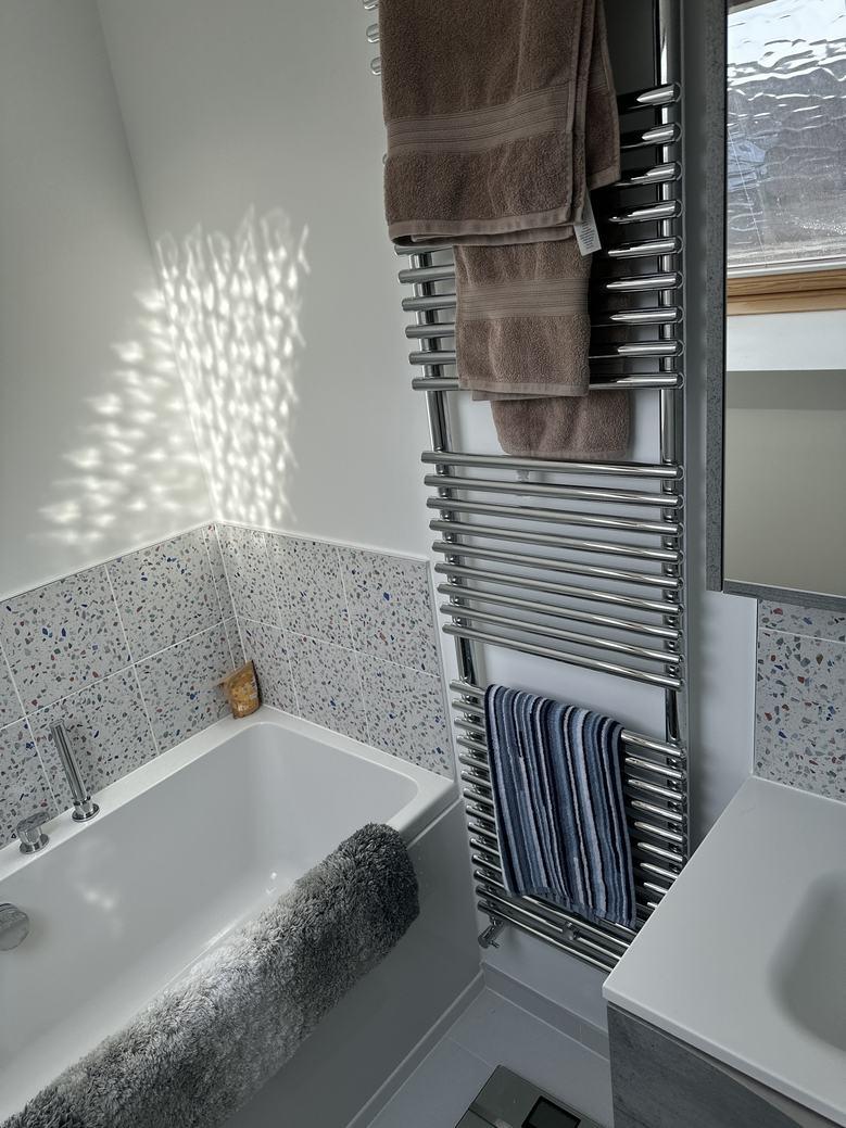
SKYLIGHT Dimensions 1.00 m x 0.73 m x 3.00 m (Width x Depth x Height)
Information Size 730x930
SKYLIGHT Dimensions 1.00 m x 0.73 m x 3.00 m (Width x Depth x Height) Velux Information Size 730x930
TOWEL RADIATOR Dimensions 0.45 m x 1.70 m (Width x Height) Distance to Floor 0.30 m THIS FLOOR PLAN IS NOTTO SCALE AND IS FOR VISUAL REPRESENTATION ONLY. PLEASE NOTE, SOME MEASUREMENTS PRESENT MAY NOT BE ACTUAL MEASUREMENTS - REGENERTEC CONSULTING OBTAIN MEASUREMENTS FOR INTERNAL AND EXTERNAL WALLS FOR THE PURPOSES OF COMPLETING HEAT LOSS CALCULATIONS ONLY. ALL OTHER MEASUREMENTS ARE FOR GUIDANCE ONLY AND REGENERTEC CONSULTING ACCEPT NO LIABILITY FOR THE ACCURACY OF THESE MEASUREMENTS IF USED FOR ALTERNATIVE PURPOSES. Page 43/59
Velux
61
63
▼ Bathroom/2nd Floor
63 TOWEL RADIATOR
Photos
2 Photos (see photos page)
Towel Rail Information
Towel Rail Type
Dual Fuel (Central Heating & Electric)
Does the Towel Rail have its own Thermostat?
No
Height 1700
Width 450
THIS FLOOR PLAN IS NOTTO SCALE AND IS FOR VISUAL REPRESENTATION ONLY. PLEASE NOTE, SOME MEASUREMENTS PRESENT MAY NOT BE ACTUAL MEASUREMENTS - REGENERTEC CONSULTING OBTAIN MEASUREMENTS FOR INTERNAL AND EXTERNAL WALLS FOR THE PURPOSES OF COMPLETING HEAT LOSS CALCULATIONS ONLY. ALL OTHER MEASUREMENTS ARE FOR GUIDANCE ONLY AND REGENERTEC CONSULTING ACCEPT NO LIABILITY FOR THE ACCURACY OF THESE MEASUREMENTS IF USED FOR ALTERNATIVE PURPOSES. Page 44/59
▼
Photos/Bathroom
1
63 Towel Radiator Photo
THIS FLOOR PLAN IS NOTTO SCALE AND IS FOR VISUAL REPRESENTATION ONLY. PLEASE NOTE, SOME MEASUREMENTS PRESENT MAY NOT BE ACTUAL MEASUREMENTS - REGENERTEC CONSULTING OBTAIN MEASUREMENTS FOR INTERNAL AND EXTERNAL WALLS FOR THE PURPOSES OF COMPLETING HEAT LOSS CALCULATIONS ONLY. ALL OTHER MEASUREMENTS ARE FOR GUIDANCE ONLY AND REGENERTEC CONSULTING ACCEPT NO LIABILITY FOR THE ACCURACY OF THESE MEASUREMENTS IF USED FOR ALTERNATIVE PURPOSES. Page 45/59
63 Towel Radiator Photo
2
▼
▼
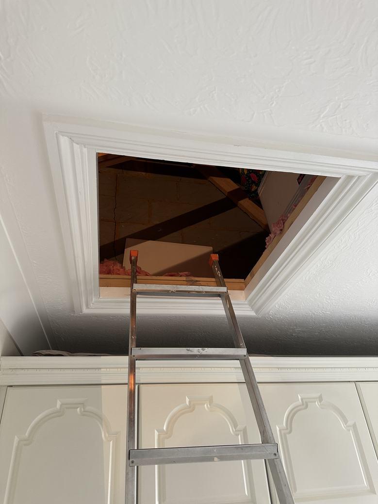
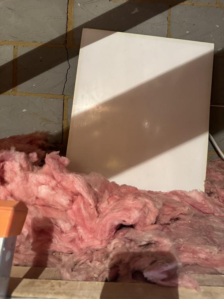
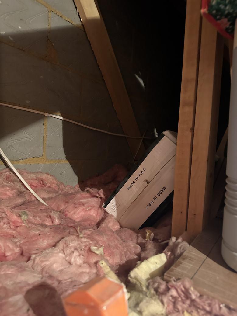
64 LOFT HATCH
Photos
8 Photos (see photos page)
65 FRENCH WINDOW
Dimensions
66
Dimensions 0.90 m x 0.50 m (Width x Height)
Photos 2 Photos (see photos page)
Radiator
Bedroom 2 2nd Floor WIDTH: 3.26 m •LENGTH: 3.67 m • CEILING HEIGHT: 2.34 m AREA: 10.89 m² • PERIMETER: 13.56 m arty Wall 0.78 0.88 0.78 2.43 0.83 1.09 1.81 0.59 0.76 0.91 0.80 1.74 2.65 3.67 3.26 3.67 66 67 68 69 70 65 Loft Hatch 64
Bedroom 2/2nd Floor
Floor
0.88 m x 1.03 m (Width x Height) Distance to
1.00 m
WATER RADIATOR
Floor
Distance to
0.00 m
Information THIS FLOOR PLAN IS NOTTO SCALE AND IS FOR VISUAL REPRESENTATION ONLY. PLEASE NOTE, SOME MEASUREMENTS PRESENT MAY NOT BE ACTUAL MEASUREMENTS - REGENERTEC CONSULTING OBTAIN MEASUREMENTS FOR INTERNAL AND EXTERNAL WALLS FOR THE PURPOSES OF COMPLETING HEAT LOSS CALCULATIONS ONLY. ALL OTHER MEASUREMENTS ARE FOR GUIDANCE ONLY AND REGENERTEC CONSULTING ACCEPT NO LIABILITY FOR THE ACCURACY OF THESE MEASUREMENTS IF USED FOR ALTERNATIVE PURPOSES. Page 46/59
▼
Bedroom
66 WATER RADIATOR Radiator Type 11 Height 500 Width 900 67 HINGED DOOR Dimensions 0.80 m x 2.04 m (Width x Height) Distance to Floor 0.00 m THIS FLOOR PLAN IS NOTTO SCALE AND IS FOR VISUAL REPRESENTATION ONLY. PLEASE NOTE, SOME MEASUREMENTS PRESENT MAY NOT BE ACTUAL MEASUREMENTS - REGENERTEC CONSULTING OBTAIN MEASUREMENTS FOR INTERNAL AND EXTERNAL WALLS FOR THE PURPOSES OF COMPLETING HEAT LOSS CALCULATIONS ONLY. ALL OTHER MEASUREMENTS ARE FOR GUIDANCE ONLY AND REGENERTEC CONSULTING ACCEPT NO LIABILITY FOR THE ACCURACY OF THESE MEASUREMENTS IF USED FOR ALTERNATIVE PURPOSES. Page 47/59
2/2nd Floor
RC1827TOTAL AREA: 179.14 m² • LIVING AREA: 166.34 m² • FLOORS: 3
Photos/Bedroom
Loft Hatch Photo 1
▼
2 64
64 Loft Hatch Photo 3
64 Loft Hatch Photo 2
4
Loft
5
64 Loft Hatch Photo
64
Hatch Photo
THIS FLOOR PLAN IS NOTTO SCALE AND IS FOR VISUAL REPRESENTATION ONLY. PLEASE NOTE, SOME MEASUREMENTS PRESENT MAY NOT BE ACTUAL MEASUREMENTS - REGENERTEC CONSULTING OBTAIN MEASUREMENTS FOR INTERNAL AND EXTERNAL WALLS FOR THE PURPOSES OF COMPLETING HEAT LOSS CALCULATIONS ONLY. ALL OTHER MEASUREMENTS ARE FOR GUIDANCE ONLY AND REGENERTEC CONSULTING ACCEPT NO LIABILITY FOR THE ACCURACY OF THESE MEASUREMENTS IF USED FOR ALTERNATIVE PURPOSES. Page 48/59
64 Loft Hatch Photo 6
RC1827TOTAL AREA: 179.14 m² • LIVING AREA: 166.34 m² • FLOORS: 3
▼ Photos/Bedroom 2
64 Loft Hatch Photo 7
64 Loft Hatch Photo 8
66 Water Radiator Photo 1
THIS FLOOR PLAN IS NOTTO SCALE AND IS FOR VISUAL REPRESENTATION ONLY. PLEASE NOTE, SOME MEASUREMENTS PRESENT MAY NOT BE ACTUAL MEASUREMENTS - REGENERTEC CONSULTING OBTAIN MEASUREMENTS FOR INTERNAL AND EXTERNAL WALLS FOR THE PURPOSES OF COMPLETING HEAT LOSS CALCULATIONS ONLY. ALL OTHER MEASUREMENTS ARE FOR GUIDANCE ONLY AND REGENERTEC CONSULTING ACCEPT NO LIABILITY FOR THE ACCURACY OF THESE MEASUREMENTS IF USED FOR ALTERNATIVE PURPOSES. Page 49/59
66 Water Radiator Photo 2
▼ Closet 2nd Floor WIDTH: 1.41 m •LENGTH: 0.36 m • CEILING HEIGHT: 2.34 m AREA: 0.43 m² • PERIMETER: 3.31 m rty Wall 1.41 0.59 0.62 0.94 71 ▼ Closet/2nd Floor 71 HINGED DOOR Dimensions 0.59 m x 2.04 m (Width x Height) Distance to Floor 0.00 m THIS FLOOR PLAN IS NOTTO SCALE AND IS FOR VISUAL REPRESENTATION ONLY. PLEASE NOTE, SOME MEASUREMENTS PRESENT MAY NOT BE ACTUAL MEASUREMENTS - REGENERTEC CONSULTING OBTAIN MEASUREMENTS FOR INTERNAL AND EXTERNAL WALLS FOR THE PURPOSES OF COMPLETING HEAT LOSS CALCULATIONS ONLY. ALL OTHER MEASUREMENTS ARE FOR GUIDANCE ONLY AND REGENERTEC CONSULTING ACCEPT NO LIABILITY FOR THE ACCURACY OF THESE MEASUREMENTS IF USED FOR ALTERNATIVE PURPOSES. Page 50/59
Cupboard 2nd Floor WIDTH: 0.91 m •LENGTH: 1.81 m • CEILING HEIGHT: 2.34 m AREA: 1.65 m² • PERIMETER: 5.44 m rty Wall 0.91 0.57 1.09 1.81 0.91 1.81 72 73
Cupboard /2nd Floor
HINGED DOOR Dimensions 0.57 m x 2.04 m (Width x Height) Distance to Floor 0.00 m 73 DOUBLE HINGED DOOR Dimensions 1.09 m x 2.04 m (Width x Height) Distance to Floor 0.00 m THIS FLOOR PLAN IS NOTTO SCALE AND IS FOR VISUAL REPRESENTATION ONLY. PLEASE NOTE, SOME MEASUREMENTS PRESENT MAY NOT BE ACTUAL MEASUREMENTS - REGENERTEC CONSULTING OBTAIN MEASUREMENTS FOR INTERNAL AND EXTERNAL WALLS FOR THE PURPOSES OF COMPLETING HEAT LOSS CALCULATIONS ONLY. ALL OTHER MEASUREMENTS ARE FOR GUIDANCE ONLY AND REGENERTEC CONSULTING ACCEPT NO LIABILITY FOR THE ACCURACY OF THESE MEASUREMENTS IF USED FOR ALTERNATIVE PURPOSES. Page 51/59
▼
▼
72
▼
▼
Bedroom 3 / Study/2nd Floor
75 FRENCH WINDOW
Dimensions 0.90 m x 1.19 m (Width x Height)
Distance to Floor 1.00 m
76 WATER RADIATOR
Dimensions 0.90 m x 0.40 m (Width x Height)
Distance to Floor 0.00 m
Photos 2 Photos (see photos page)
Radiator Information
Radiator Type 11
Bedroom 3
Floor WIDTH: 3.27 m •LENGTH: 5.20 m • CEILING HEIGHT: 2.34 m AREA: 14.92 m² • PERIMETER: 16.94 m rty Wall 1.77 0.80 2.63 1.47 0.64 1.34 1.91 0.63 1.82 0.90 0.90 0.84 2.64 5.20 3.27 76 74 77 75
/ Study 2nd
Height
THIS FLOOR PLAN IS NOTTO SCALE AND IS FOR VISUAL REPRESENTATION ONLY. PLEASE NOTE, SOME MEASUREMENTS PRESENT MAY NOT BE ACTUAL MEASUREMENTS - REGENERTEC CONSULTING OBTAIN MEASUREMENTS FOR INTERNAL AND EXTERNAL WALLS FOR THE PURPOSES OF COMPLETING HEAT LOSS CALCULATIONS ONLY. ALL OTHER MEASUREMENTS ARE FOR GUIDANCE ONLY AND REGENERTEC CONSULTING ACCEPT NO LIABILITY FOR THE ACCURACY OF THESE MEASUREMENTS IF USED FOR ALTERNATIVE PURPOSES. Page 52/59
400
▼
3 / Study/2nd Floor
76 WATER RADIATOR Width 900 THIS FLOOR PLAN IS NOTTO SCALE AND IS FOR VISUAL REPRESENTATION ONLY. PLEASE NOTE, SOME MEASUREMENTS PRESENT MAY NOT BE ACTUAL MEASUREMENTS - REGENERTEC CONSULTING OBTAIN MEASUREMENTS FOR INTERNAL AND EXTERNAL WALLS FOR THE PURPOSES OF COMPLETING HEAT LOSS CALCULATIONS ONLY. ALL OTHER MEASUREMENTS ARE FOR GUIDANCE ONLY AND REGENERTEC CONSULTING ACCEPT NO LIABILITY FOR THE ACCURACY OF THESE MEASUREMENTS IF USED FOR ALTERNATIVE PURPOSES. Page 53/59
Bedroom
▼ Photos/Bedroom 3 / Study 76 Water Radiator Photo 1 76 Water Radiator Photo 2 THIS FLOOR PLAN IS NOTTO SCALE AND IS FOR VISUAL REPRESENTATION ONLY. PLEASE NOTE, SOME MEASUREMENTS PRESENT MAY NOT BE ACTUAL MEASUREMENTS - REGENERTEC CONSULTING OBTAIN MEASUREMENTS FOR INTERNAL AND EXTERNAL WALLS FOR THE PURPOSES OF COMPLETING HEAT LOSS CALCULATIONS ONLY. ALL OTHER MEASUREMENTS ARE FOR GUIDANCE ONLY AND REGENERTEC CONSULTING ACCEPT NO LIABILITY FOR THE ACCURACY OF THESE MEASUREMENTS IF USED FOR ALTERNATIVE PURPOSES. Page 54/59
78
Photos
Photos (see photos page) 79
Cylinder Cupboard 2nd Floor WIDTH: 0.93 m •LENGTH: 1.90 m • CEILING HEIGHT: 2.34 m AREA: 1.77 m² • PERIMETER: 5.66 m rty Wall 1.90 0.93 1.32 0.50 1.90 0.93 78 79
Cylinder Cupboard /2nd Floor
▼
▼
GAS WATER
0.63 m
m x 2.00 m (Width x Depth x Height)
HEATER Dimensions
x 0.63
8
HINGED DOOR
0.50 m x 2.04 m (Width x Height) Distance to Floor 0.00 m THIS FLOOR PLAN IS NOTTO SCALE AND IS FOR VISUAL REPRESENTATION ONLY. PLEASE NOTE, SOME MEASUREMENTS PRESENT MAY NOT BE ACTUAL MEASUREMENTS - REGENERTEC CONSULTING OBTAIN MEASUREMENTS FOR INTERNAL AND EXTERNAL WALLS FOR THE PURPOSES OF COMPLETING HEAT LOSS CALCULATIONS ONLY. ALL OTHER MEASUREMENTS ARE FOR GUIDANCE ONLY AND REGENERTEC CONSULTING ACCEPT NO LIABILITY FOR THE ACCURACY OF THESE MEASUREMENTS IF USED FOR ALTERNATIVE PURPOSES. Page 55/59
Dimensions
▼ Photos/Cylinder Cupboard 78 Gas Water Heater Photo 1 78 Gas Water Heater Photo 2 78 Gas Water Heater Photo 3 78 Gas Water Heater Photo 4 78 Gas Water Heater Photo 5 78 Gas Water Heater Photo 6 THIS FLOOR PLAN IS NOTTO SCALE AND IS FOR VISUAL REPRESENTATION ONLY. PLEASE NOTE, SOME MEASUREMENTS PRESENT MAY NOT BE ACTUAL MEASUREMENTS - REGENERTEC CONSULTING OBTAIN MEASUREMENTS FOR INTERNAL AND EXTERNAL WALLS FOR THE PURPOSES OF COMPLETING HEAT LOSS CALCULATIONS ONLY. ALL OTHER MEASUREMENTS ARE FOR GUIDANCE ONLY AND REGENERTEC CONSULTING ACCEPT NO LIABILITY FOR THE ACCURACY OF THESE MEASUREMENTS IF USED FOR ALTERNATIVE PURPOSES. Page 56/59
Cupboard 78 Gas Water Heater Photo 7 78 Gas Water Heater Photo 8 THIS FLOOR PLAN IS NOTTO SCALE AND IS FOR VISUAL REPRESENTATION ONLY. PLEASE NOTE, SOME MEASUREMENTS PRESENT MAY NOT BE ACTUAL MEASUREMENTS - REGENERTEC CONSULTING OBTAIN MEASUREMENTS FOR INTERNAL AND EXTERNAL WALLS FOR THE PURPOSES OF COMPLETING HEAT LOSS CALCULATIONS ONLY. ALL OTHER MEASUREMENTS ARE FOR GUIDANCE ONLY AND REGENERTEC CONSULTING ACCEPT NO LIABILITY FOR THE ACCURACY OF THESE MEASUREMENTS IF USED FOR ALTERNATIVE PURPOSES. Page 57/59
▼ Photos/Cylinder
Landing 2nd Floor WIDTH: 2.65 m •LENGTH: 1.78 m • CEILING HEIGHT: 2.34 m AREA: 4.71 m² • PERIMETER: 8.86 m rty Wall 1.74 0.80 2.65 0.80 1.78 0.80 1.78 2.65 1.78 80 82 83 84 81
Landing /2nd Floor
L-SHAPED STAIRCASE Dimensions 1.78 m x 1.60 m x 2.00 m (Width x Depth x Height)
SKYLIGHT Dimensions 0.73 m x 0.63 m x 3.00 m (Width x Depth x Height) Velux Information Size 600x690
HINGED DOOR Dimensions 0.80 m x 2.04 m (Width x Height) Distance to Floor 0.00 m 84 HINGED DOOR Dimensions 0.80 m x 2.04 m (Width x Height) THIS FLOOR PLAN IS NOTTO SCALE AND IS FOR VISUAL REPRESENTATION ONLY. PLEASE NOTE, SOME MEASUREMENTS PRESENT MAY NOT BE ACTUAL MEASUREMENTS - REGENERTEC CONSULTING OBTAIN MEASUREMENTS FOR INTERNAL AND EXTERNAL WALLS FOR THE PURPOSES OF COMPLETING HEAT LOSS CALCULATIONS ONLY. ALL OTHER MEASUREMENTS ARE FOR GUIDANCE ONLY AND REGENERTEC CONSULTING ACCEPT NO LIABILITY FOR THE ACCURACY OF THESE MEASUREMENTS IF USED FOR ALTERNATIVE PURPOSES. Page 58/59
▼
▼
80
81
82
▼ Landing /2nd Floor
HINGED DOOR Distance to Floor 0.00 m THIS FLOOR PLAN IS NOTTO SCALE AND IS FOR VISUAL REPRESENTATION ONLY. PLEASE NOTE, SOME MEASUREMENTS PRESENT MAY NOT BE ACTUAL MEASUREMENTS - REGENERTEC CONSULTING OBTAIN MEASUREMENTS FOR INTERNAL AND EXTERNAL WALLS FOR THE PURPOSES OF COMPLETING HEAT LOSS CALCULATIONS ONLY. ALL OTHER MEASUREMENTS ARE FOR GUIDANCE ONLY AND REGENERTEC CONSULTING ACCEPT NO LIABILITY FOR THE ACCURACY OF THESE MEASUREMENTS IF USED FOR ALTERNATIVE PURPOSES. Page 59/59
84
Room Temperature Design Waiver
Client Details
Survey Reference Number RC1827
Survey Date 24/01/2024
Client Name
Property Address
Room Design Temperatures
All Heat Pump (Air, Ground or Water Source) installations are required to be designed in compliance with MCS to be eligible for any government funding and/or incentives. The designing process entails Heat Loss Calculations to be carried out to ensure the equipment being installed is sufficient to meet the properties space heating and hot water demand.
Room Design Temperatures
Below are the internal design temperatures for relevant spaces which are used to maintain compliance with MCS. These temperatures are also in line with the UK national annex to BS EN 12831. All rooms will be designed with a flow temperature of between 35-55c depending on the heat emitter servicing the rooms heat demand.
Please select yes to all the room temperatures below that you are happy with.
Please note, these temperatures are minimum design temperatures that must be used to ensure compliance. However, they can be increased above those stated below where required. Please advise the surveyor which rooms you desire to be warmer and to what temperatures so that the design can be completed accordingly.
Was the Property Built Post 2006? No
Post 2006 Built Properties Where domestic dwellings are built post 2006, CIBSE Design Guide A recommends that all rooms are designed at 21°c except bathrooms are designed at 22°c and store rooms 16°c.
Year of Build 1998
Client Decision Regarding Design Temperature Utilize Standard MCS Temperatures - Outlined Below
Living Rooms and Sitting Rooms are designed at 21°c Yes Dining Rooms and Breakfast Rooms are designed at 21°c Yes Play Rooms are designed at 21°c Yes
are designed at 18°c Yes
Rooms are designed at 18°c Yes Kitchen / Dining Rooms are designed at 21°c Yes Toilets and Cloakrooms are designed at 18°c Yes Conservatories are designed at 18°c N/A Bedrooms are designed at 18°c Yes Bedroom / Study's are designed at 21°c Yes
Kitchens
Utility
Page 1 of 2
Room Temperature Design Waiver
Bedsitting Rooms are designed at 21°c
Halls, Porches, Corridors and Landings are designed at 18°c
Bathrooms, Shower Rooms and En-suite's are designed at 22°c Yes
Due to the lower flow temperatures provided by Heat Pumps, some emitters in each rooms may require to be upgraded. Any required radiator upgrades will be determined upon completion of Heat Loss Calculations and existing emitter schedule assessment (if applicable).
I/We confirm the surveyor in attendance has individually surveyed each room of My/Our property. I/We understand the purpose of the room design temperatures and accept that; unless advised otherwise it will be done in accordance with MCS guidelines and temperatures stated above. I/We also understand that it may not be possible to reach the necessary temperature in each room and cannot be advised of this until relevant calculations have been completed.
By signing this document you agree for the surveyor to use the above stated minimum room design temperatures for your heat pumps design and Heat Loss Calculations. Unless stated otherwise in the comments and advice section the minimum design temperatures will be used.
Yes
Yes
Client Signature Print Name Date 24/01/2024 Surveyor Signature Print Name Date 24/01/2024
Page 2 of 2
▼ Ground Floor TOTAL AREA: 88.65 m² •LIVING AREA: 75.85 m² • UFH Manifold Roof Lantern 780x570 Solar PV Inverter & Batteries
Wall 1 Kitchen / Dining Room Cupboard
4 / Study
Room Cupboard Hall Sitting Room Garage THIS FLOOR PLAN IS NOTTO SCALE AND IS FOR VISUAL PURPOSES ONLY. THIS FLOOR PLAN IS NOTTOO BE USED FOR ARCHITECTURAL REASONS. Page 1/3
Party
Bedroom
Shower
▼ 1st Floor TOTAL AREA: 49.94 m² •LIVING AREA: 49.94 m² • Party Wall 14 Living Room Landing Bedroom 1 En-suite THIS FLOOR PLAN IS NOTTO SCALE AND IS FOR VISUAL PURPOSES ONLY. THIS FLOOR PLAN IS NOTTOO BE USED FOR ARCHITECTURAL REASONS. Page 2/3
Bedroom
Bedroom
▼ 2nd Floor TOTAL AREA: 40.55 m² •LIVING AREA: 40.55 m² • Loft Hatch
Party Wall
Cylinder Cupboard
3
Study Landing
/
Bathroom
2 Closet Cupboard THIS FLOOR PLAN IS NOTTO SCALE AND IS FOR VISUAL PURPOSES ONLY. THIS FLOOR PLAN IS NOTTOO BE USED FOR ARCHITECTURAL REASONS. Page 3/3
On Site Risk Assessment
Client Details
Survey Reference Number RC1827
Assessment Date 24/01/2024
Client Name
Property Address
Survey Conducted on Behalf Of ARC One Group Risk Assessment
This risk assessment has been completed for the proposed installation of either an air or ground source heat pump.
The assessment is made using a scale from 1-5. 1 being highly unlikely and 5 being a severe risk.
Additional Notes / Findings
COVID-19 Safety Measures
Social distancing was maintained at all times where possible.
Surveyors Signature
Print Name
Working from height 3 - Quite Likely Unstable ground 2 - Fairly Unlikely Working on fragile surfaces 3 - Quite Likely Dangerous parking 2 - Fairly Unlikely Working in lofts or confined spaces 3 - Quite Likely Exposure to dangerous gasses or naked flames 2 - Fairly Unlikely Personal injury leading to cuts and/or burns 2 - Fairly Unlikely Working around vulnerable persons or aggressive animals 1 - Highly Unlikely
facemask was worn during the survey at all times. Not
gloves
during
survey
Not
A
Required Disposable
were worn
the
at all times.
Required
Yes
Page 1 of 2

On Site Risk Assessment
Date/Time
24/01/2024
This risk assessment was prepared for the purpose of the Heat Loss Survey. Any works commencing after the date of this risk assessment require a separate risk assessment specific to the working methods proposed.
Page 2 of 2
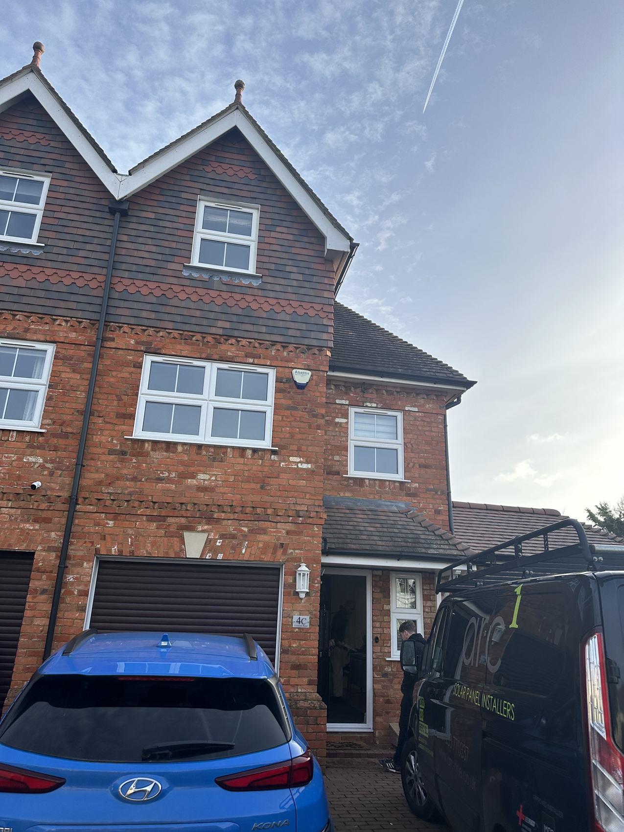
Client
Information Survey Reference Number RC1827 Survey Date 24/01/2024 Survey Purpose Heat Loss Survey Installation Company ARC One Group Client Name Client Email Address Contact Number Property Address Property Information Property Type End-Terrace House Number of Bedrooms 4 Number of Bathrooms 3 Number of Floors 3 Is the Property Located Within a Conservation Area? Yes Is the Property Listed? No Date of Construction 1998 Has the Property Been Extended? Yes Quantity of Extensions Completed 1 Extension 1 Construction Date 2014 - Side single storey extension Is the Property due to be Extended? No Has the Property got a Valid Energy Performance Certificate? Yes Current EPC Date 27/07/2022 Is there a Recommendation for Loft Insulation on the Current EPC? No Is there a Recommendation for Cavity Wall Insulation on the Current EPC? No
Insulation
External Wall Type Filled Cavity - As Built Extension(s) External Wall Type(s) Filled Cavity - As Built Party Wall Type Solid Block Heat Loss Property Information
Page 1 of 9
Building Construction /
Details Main
Form
Heat Loss Property Information Form
Internal Wall Type Block, Stud
Ground Floor Type Solid - Uninsulated
Dividing Floor Construction Solid - Uninsulated, Solid - Insulated
Glazing Type UPVC / Wood Double Glazing
Date of Glazing Installation / Replacement Unknown except rear ground floor 2023
Roof Space Insulation Thickness (mm) 200-250mm
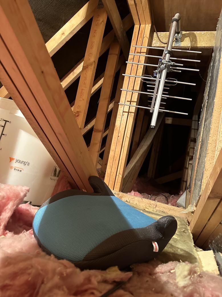
Roof Space Area of Insulation Joists
Roof Space Access Details Loft Hatch
Loft Hatch Size 680x575
Roof Space Ridge Height (m) 1.85m
New Extension - Building Construction / Insulation Details
Are Plans Available for the New Extension? N/A
Roof Space Insulation Thickness (mm)/ U-value
Current Standards 0.15W/m2K
Existing Heating and Hot Water Details
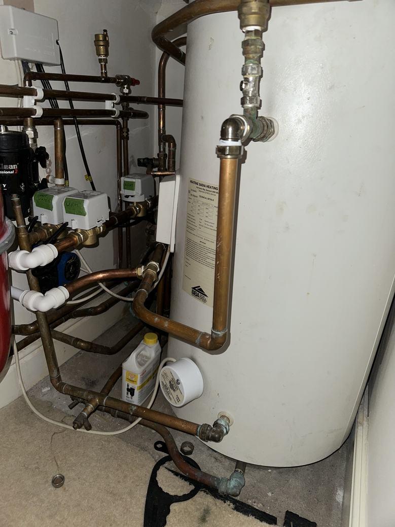
Current Heat Source Mains Gas
Current Heat Emitter(s) Radiators, Towel Rails, Underfloor Heating
Radiator Pipework Type Standard (>15mm)
Radiator Flow and Return Size (mm) 15mm
Is there Underfloor Heating Present at the Property? Yes
Underfloor Heating Manifold Location(s) Hall cupboard
Underfloor Heating Installation Date 2023
Are there Pipework Layouts Available for the Underfloor Heating?
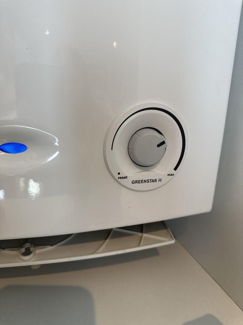
Boiler Type Standard
Boiler Details Worcester Greenstar Ri
Boiler Age
Current Boiler Location Located wall mounted within the kitchen cupboard
No
Property
Thermostatic
Yes Number of Zones 2 Quantity of Boilers Present 1
Does the
have Zoned
Control?
Unknown
Page 2 of 9
Heat Loss Property Information Form
Is the Boiler Located Along an External Wall?
Boiler Flow and Return Size (mm) 22mm
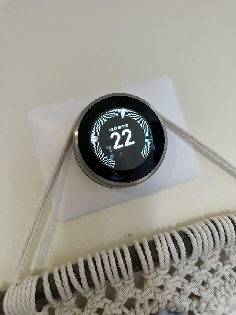
Main Thermostat Location Hall Programmer Location Nest
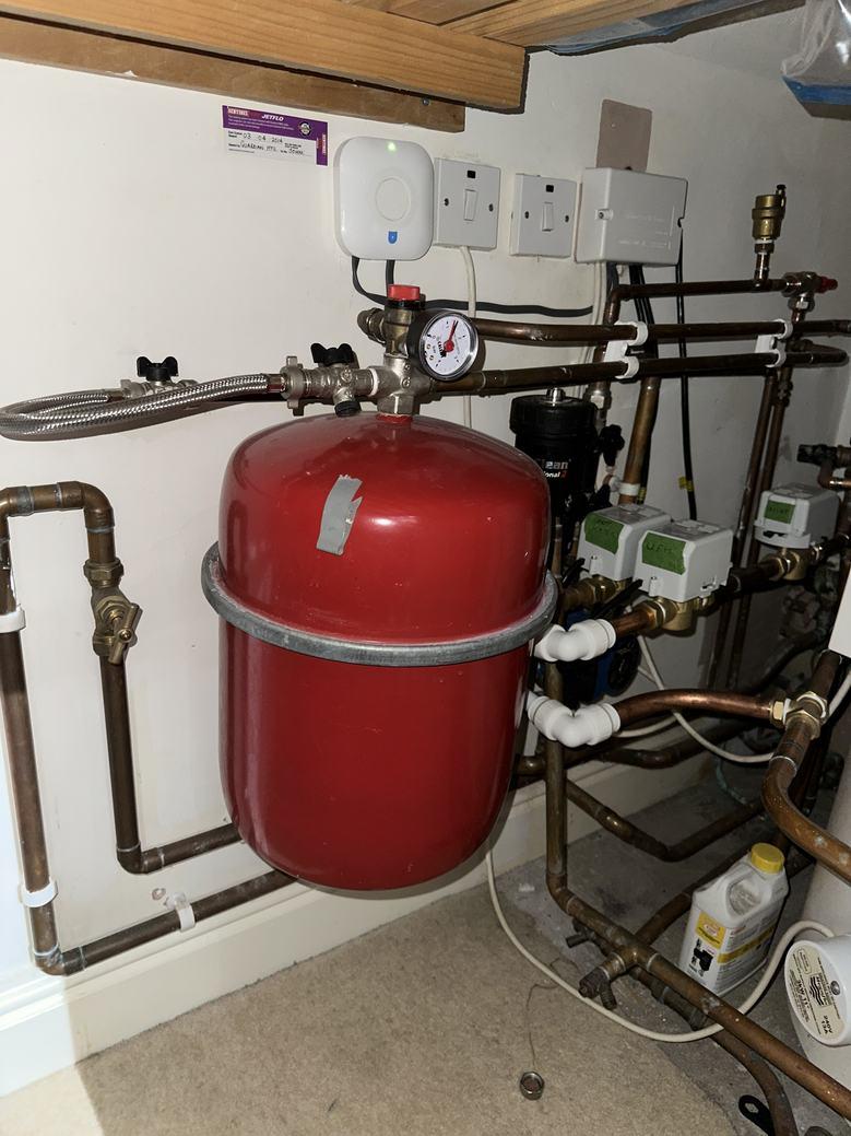
Main Hot Water Cylinder Location Second floor bedroom 3 cupboard How is the Hot Water Heated? Boiler, Immersion, Solar iBoost
Is the Hot Water Cylinder Along an
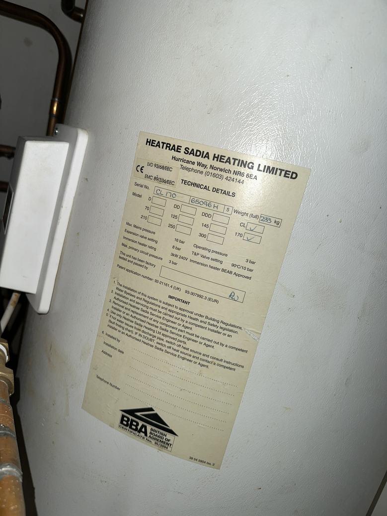
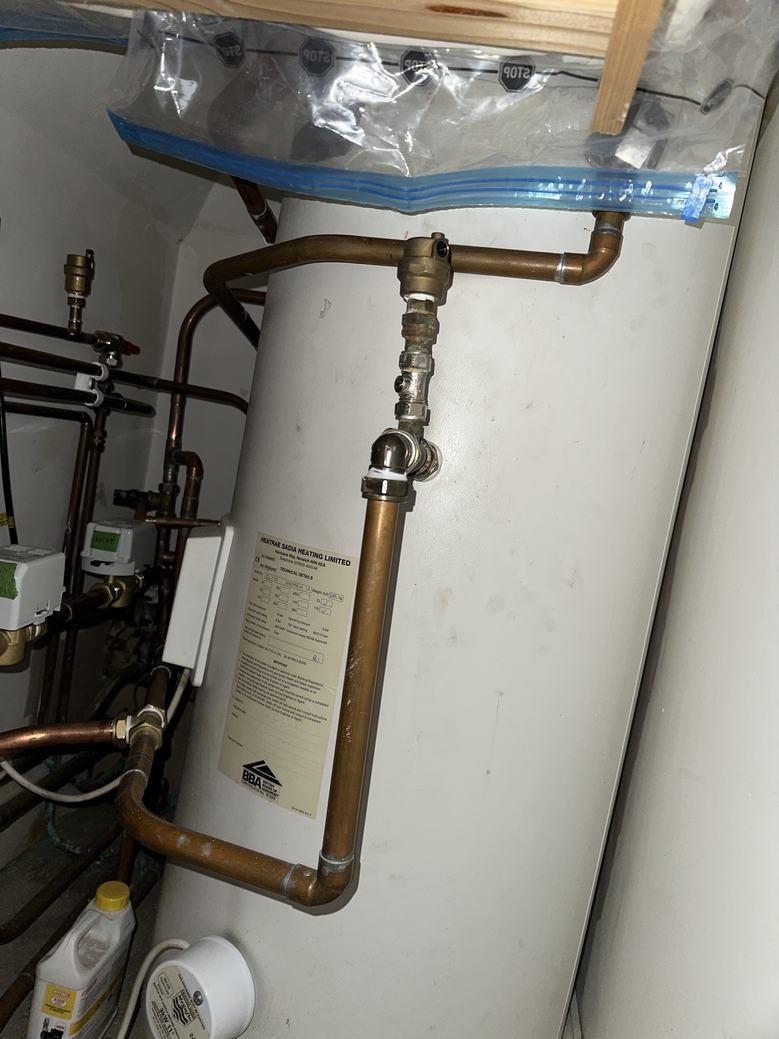
Main Hot Water Cylinder Details Heatrae Sadia CL170
Main
Main
Main
Size 930D x 1900W x 2000-1100H (sloping due to roof)
Is there Solar Thermal Present? No
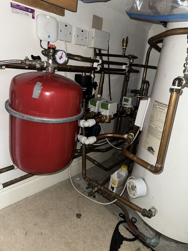
Is there a Hot Water Power Diverter Present? Yes
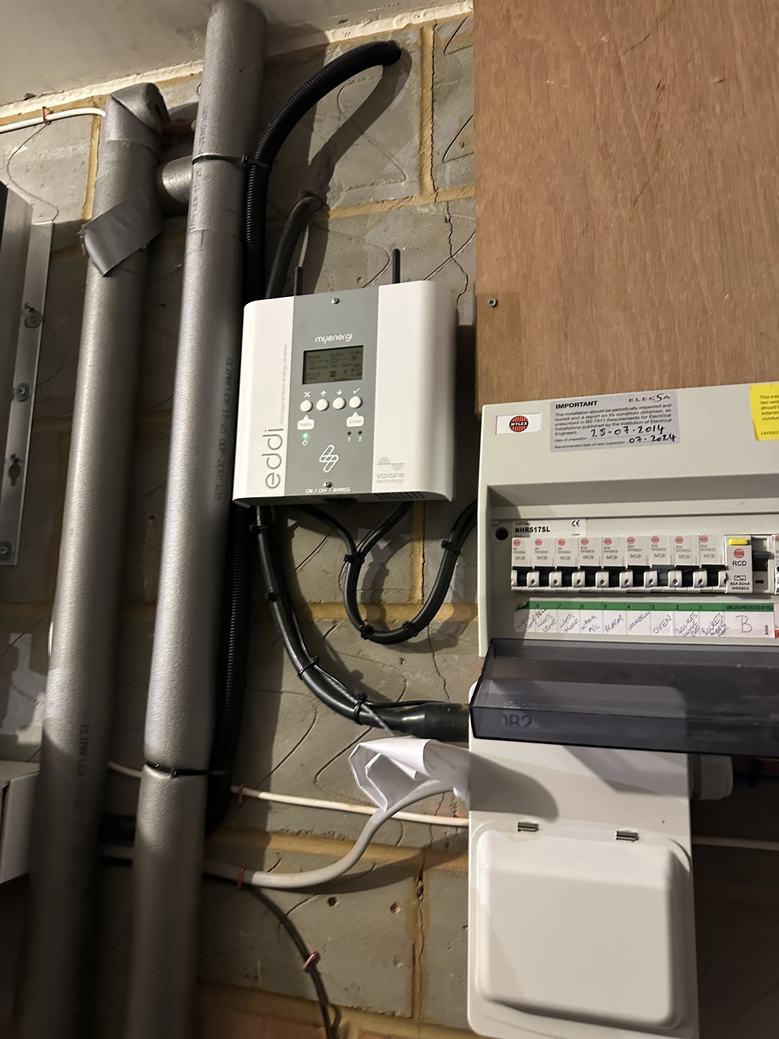
Hot Water Power Diverter Details Eddi hot water power diverter
Is there Filter Protection? Yes
Is there a Water Softener
Secondary Heating N/A
Is there Mechanical Ventilation Heat Recovery (MVHR) Present at the Property?
Existing Electrical Details
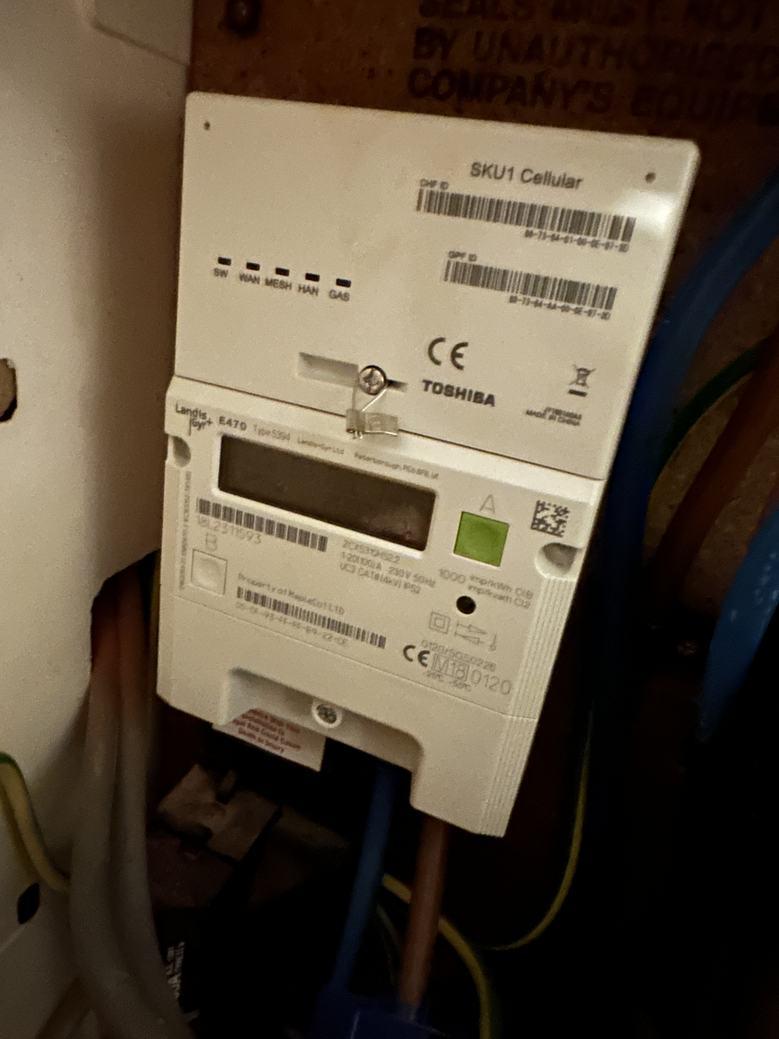
Incoming Mains Location Garage
Incoming Mains Make / Model Landis & Gyr
Mains Supply Type Single Phase
Incoming Fuse Size (A) 100A
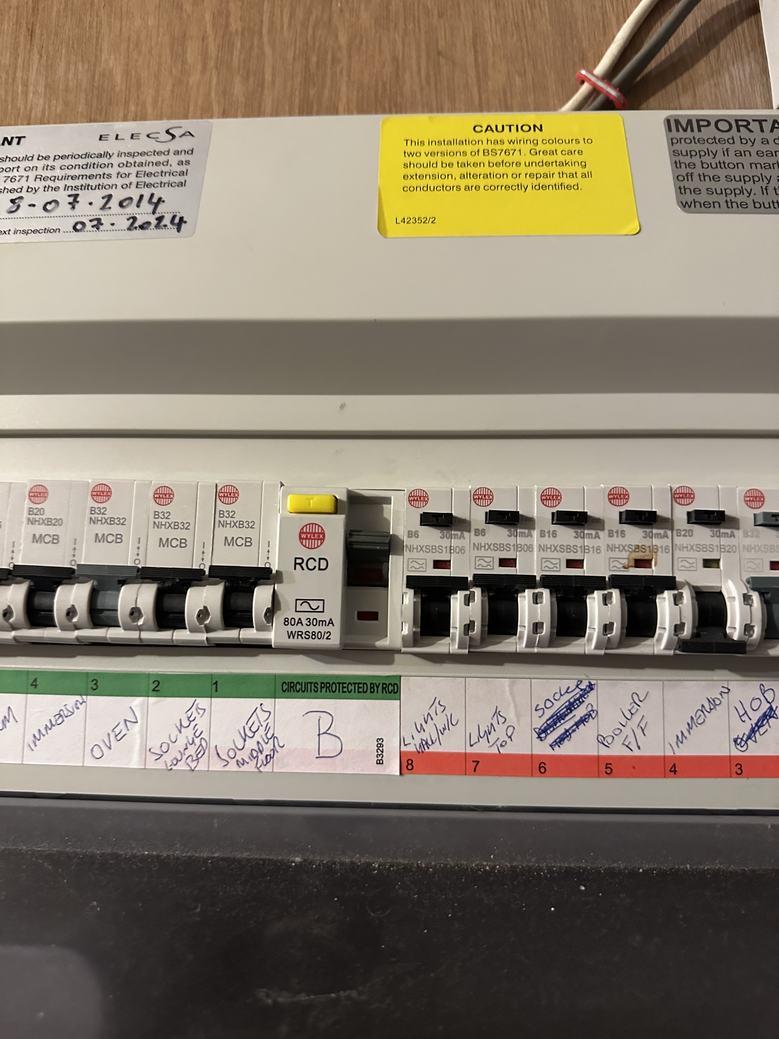
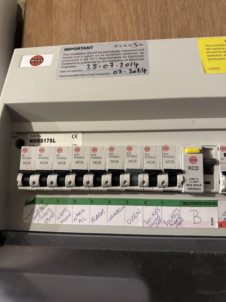
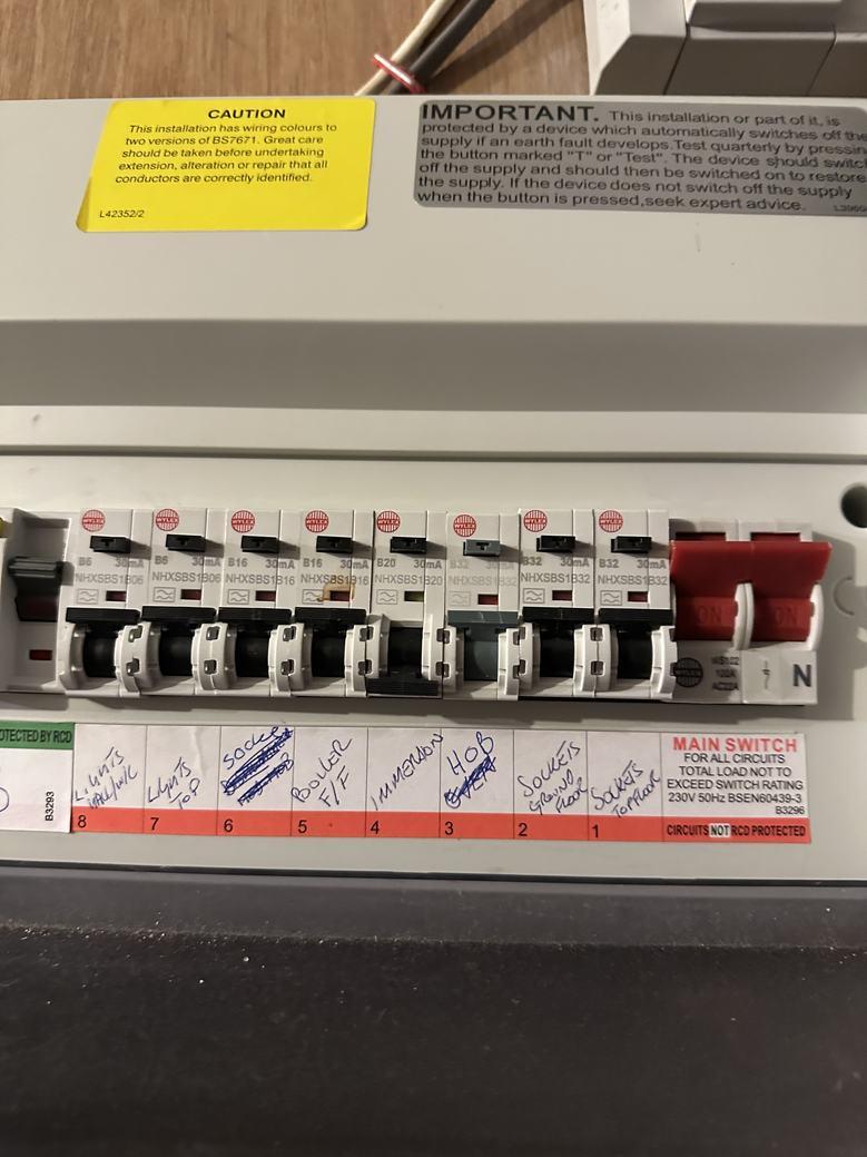
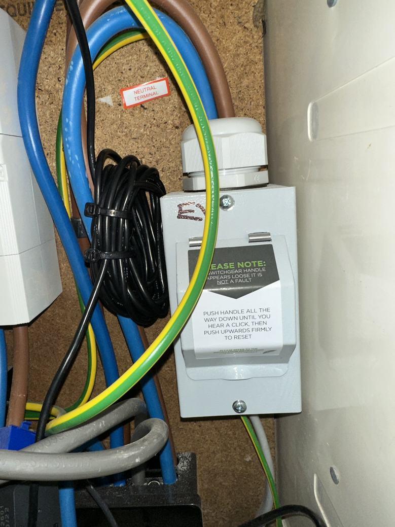
Main Consumer Unit Location Garage
Main Consumer Unit Make / Model Wylex
Yes
Quantity
of Thermostats Present 2
Present?
Quantity
Present
Is there a Hot Water Cylinder
Yes
of Hot Water Cylinders
1
External
Wall? Yes
Hot
Cylinder Capacity (L)
Water
170L
Flow
(mm)
Hot Water Cylinder
and Return Size
22mm
Cupboard
Hot Water Cylinder
Present?
No
No
Quantity of Consumer Units 2
Page 3 of 9
Heat Loss Property Information Form
Existing Renewable Technologies
Current
Hot Water Power Diverter Details Eddi hot water power diverter Was the Solar PV Installed Under the Feed-In-Tariff?
Heat Pump Installation Details
Number of Spare Ways on Main Consumer Unit 0 Is the Consumer Unit RCD Protected? Yes RCD Size (A) 80A Sub Consumer Unit Location(s) Garage Number of Spare Ways on Sub Consumer Unit(s) 0
Technologies Present
the Property Solar PV,
Quantity of Solar PV Panels Present 22 kWp of Solar PV 6kWp
Inverter Location Garage
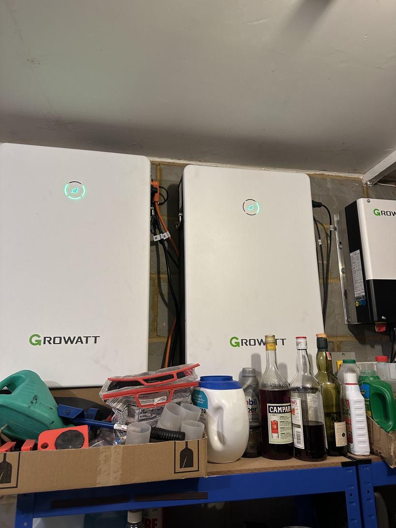
Inverter Make/Model Growatt Solar PV Installation Date 2023 Quantity of Solar Batteries Present 2 Solar Battery Details 2no Growatt
at
Solar Battery
Solar
Solar
Diverter Present? Yes
Is there a Hot Water Power
No
Type Space Heating and
Proposed Heat Pump Type Being Installed Air Source Heat Pump Proposed Heat Pump Make / Model to be Installed Midea Monobloc R32 Number of ASHP Locations Discussed 2 ASHP Outdoor Unit Location 1 To be wall mounted along the side external wall of the living room at first floor level above the extension flat roof Location 1 - Will the ASHP Location be at least 1m from any Neighbouring Boundaries? Yes Location 1 - Will the ASHP be Visible from the Roadside? Yes - Partially Visible Location 1 - ASHP Mounting Type Wall Mounted - High Level ASHP Outdoor Unit Location 2 To be ground mounted at the rear of the property along the external wall of the kitchen / sitting room
Installation
Hot Water
Page 4 of 9
Location 2 - Will the ASHP Location be at least 1m from any
Flow
Neighbouring
Yes
Boundaries?
Visible
Roadside? No
2
Mounting Type Ground Mounted Ground Conditions for ASHP Undecided Location Groundwork Requirements Undecided ASHP Location Distance from ASHP Outdoor Unit to Existing Boiler Location* (m) Option 1 - 8m / Option 2 - 2m
Water Cylinder Location 1 Replace the current cylinder within the cupboard of bedroom 3 on the second floor Proposed Hot Water Cylinder Cupboard Size - Location 1 930D x 1900W x 2000-1100H (sloping due to roof)
a Solar Thermal Cylinder Required? No
an Existing Hot Water Power Diverter Require Reconnecting? Undecided
Location 2 - Will the ASHP be
from the
Location
- ASHP
Hot
Is
Will
and Return Pipework Route(s) from Outdoor
and return pipework can go from the
and through into the cylinder
Pipework Lagging
Yes
Pipework need
go through the Roof Space? No Distance from ASHP Outdoor Unit to Incoming Mains* 12m Distance from ASHP Outdoor Unit to Consumer Unit* 12m
Emitters for ASHP Existing Underfloor Heating, Existing Radiators, New Radiators
Heat
Yes
No
the Property Require
Wall Insulation? No Is a New Energy Performance Certificate Required? No - Current EPC is Valid Will Planning Permission be Required for the Heat Pump Installation? Undecided ASHP Location Additional Property Information General Access Good Delivery Access Good Parking On Private Driveway Heat Loss Property Information Form Page 5 of 9
Unit to Hot Water Cylinder Flow
ASHP outdoor unit, up the external wall
cupboard Will
/ Insulation be Required?
Will
to
Proposed
Is the
Pump Installation intended for the Boiler Upgrade Scheme?
Is Loft Insulation Required?
Does
Cavity
Heat Loss Property Information Form
All information present on this document was obtained on the date of the survey outlined above on Page 1. The information was obtained either on physical site inspection or from advice given by the client/occupant(s) and/or the installer.
General Information
Utility Provider Unknown, bill
provided Gas Unit Rate Paid (p/kWh) Unknown, bill
provided Electricity Unit Rate Paid (p/kWh) Unknown, bill
provided MPAN Supply Number Unknown,
Signature Print Name Date/Time 24/01/2024
not
not
not
bill not provided
Page 6 of 9
Energy performance certificate (EPC)
CCertificate
Property type End-terrace
Total floor area
Rules on letting this property
Properties can be let if they have an energy rating fromAto E.
You can read guidance for landlords on the regulations and exemptions (https://www.gov.uk/guidance/domestic-private-rented-property-minimum-energy-efficiency-standard-landlordguidance)
Energy rating and score
This property’s energy rating is C. It has the potential to be B.
See how to improve this property’s energy efficiency
The graph shows this property’s current and potential energy rating.
Properties get a rating fromA(best) to G (worst) and a score. The better the rating and score, the lower your energy bills are likely to be.
For properties in England and Wales: the average energy rating is D the average energy score is 60
1/23/24, 7:08 PM Energy performance certificate (EPC) – Find an energy certificate – GOV.UK
1/4
https://find-energy-certificate.service.gov.uk/energy-certificate/3532-0823-9100-0068-8226?print=true
Energy rating
Valid until: 27 July 2032
number:3532-0823-9100-0068-8226
house
188
square metres
A B C D E F G 92+ 81-91 69-80 55-68 39-54 21-38 1-20 ScoreEnergy rating CurrentPotential 75 C 83 B
Breakdown of property’s energy performance
Features in this property
Features get a rating from very good to very poor, based on how energy efficient they are. Ratings are not based on how well features work or their condition.
Assumed ratings are based on the property’s age and type.They are used for features the assessor could not inspect.
Primary energy use
The primary energy use for this property per year is 140 kilowatt hours per square metre (kWh/m2).
How this affects your energy bills
An average household would need to spend £988 per year on heating, hot water and lighting in this property These costs usually make up the majority of your energy bills
You could save £93 per year if you complete the suggested steps for improving this property’s energy rating
This is based on average costs in 2022 when this EPC was created People living at the property may use different amounts of energy for heating, hot water and lighting
Heating this property
Estimated energy needed in this property is:
kWh per year for heating
1/23/24, 7:08 PM Energy performance certificate (EPC) – Find an energy certificate – GOVUK https://find-energy-certificate service govuk/energy-certificate/3532-0823-9100-0068-8226?print=true 2/4
Feature Description Rating Wall Cavity wall, as built, insulated (assumed) Good Roof Pitched, insulated (assumed) Good Roof Roof room(s), insulated Good Window Fully double glazed Good Main heating Boiler and radiators, mains gas Good Main heating control Programmer, room thermostat and TRVs Good Hot water From main system Good Lighting Low energy lighting in 54% of fixed outlets Good Floor Suspended, limited insulation (assumed) N/A Floor To unheated space, limited insulation (assumed) N/A Floor Solid, insulated (assumed) N/A Secondary heating None N/A
13,852
2,997
hot water
kWh per year for
Impact on the environment
This property’s environmental impact rating is C.It has the potential to be C.
Properties get a rating fromA(best) to G (worst) on how much carbon dioxide (CO2) they produce each year.
Carbon emissions
An average household produces 6 tonnes of CO2
Changes you could make
This property produces 4.6 tonnes of CO2 This property’s potential production 3.3 tonnes of CO2
You could improve this property’s CO2 emissions by making the suggested changes. This will help to protect the environment.
These ratings are based on assumptions about average occupancy and energy use. People living at the property may use different amounts of energy.
Help paying for energy improvements
You might be able to get a grant from the Boiler Upgrade Scheme (https://www.gov.uk/apply-boilerupgrade-scheme).This will help you buy a more efficient, low carbon heating system for this property.
More ways to save energy
Find ways to save energy in your home by visiting www.gov.uk/improve-energy-efficiency
1/23/24, 7:08 PM Energy performance certificate (EPC) – Find an energy certificate – GOV.UK
3/4
https://find-energy-certificate.service.gov.uk/energy-certificate/3532-0823-9100-0068-8226?print=true
Step Typical installation cost Typical yearly saving 1. Low energy lighting £110 £49 2. Solar water heating £4,000 - £6,000 £43 3. Solar photovoltaic panels £3,500 - £5,500 £364
Who to contact about this certificate
Contacting the assessor
If you’re unhappy about your property’s energy assessment or certificate, you can complain to the assessor who created it
Assessor’s name
Tiago Marques
Telephone 0203 397 8220
Email support@propcert.co.uk
Contacting the accreditation scheme
If you’re still unhappy after contacting the assessor, you should contact the assessor’s accreditation scheme
Accreditation scheme
Elmhurst Energy Systems Ltd
Assessor’s ID EES/023533
Telephone 01455 883 250
Email enquiries@elmhurstenergy.co.uk
About this assessment
Assessor’s declaration No related party
Date of assessment 28 July 2022
Date of certificate 28 July 2022
Type of assessment RdSAP
1/23/24, 7:08 PM Energy performance certificate (EPC) – Find an energy certificate – GOVUK https://find-energy-certificate service govuk/energy-certificate/3532-0823-9100-0068-8226?print=true 4/4
Site Report
Survey Date: Wednesday 24th January 2024
Installation Company: Arc One Group
Client Name:
Project Address:
Project Reference: RC1827
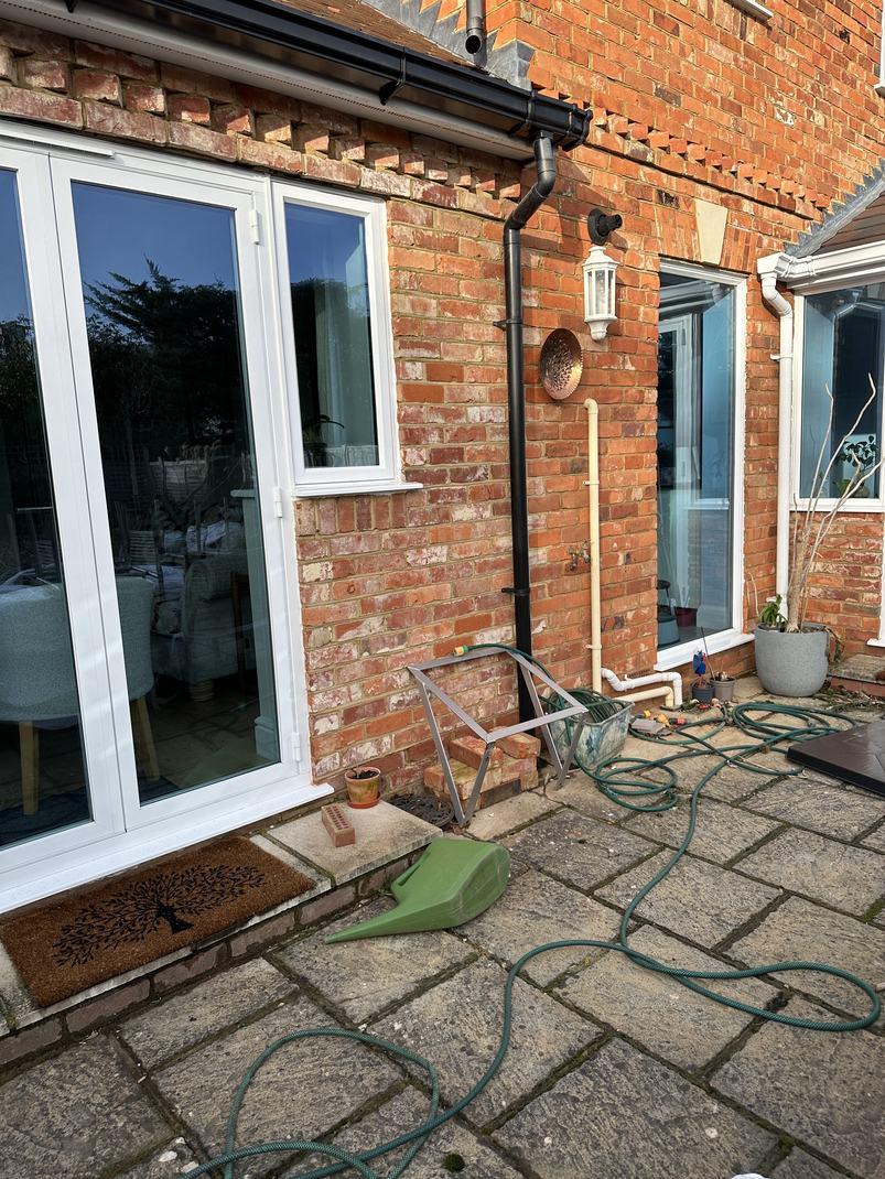
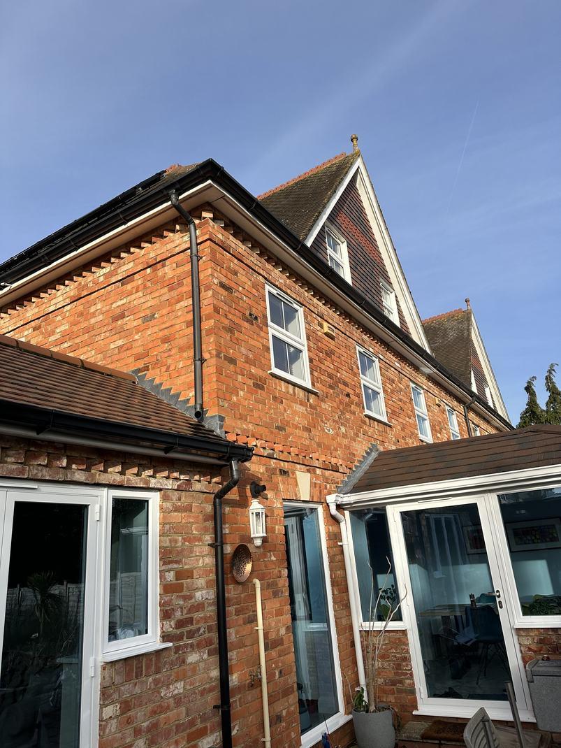
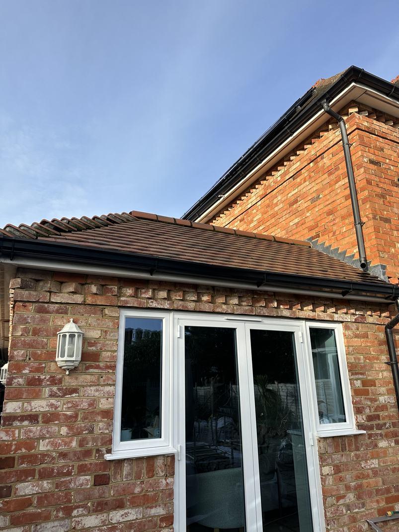
This property is a 4-bedroom end-terrace house built originally in 1998. The property has undergone a side single-storey extension in 2014. The property is located within a conservation area. The external walls are filled cavity (as built). The ground floor is solid, assumed uninsulated except with an extension is assumed insulated. The property has got UPVC double glazing throughout, the rear ground floor windows replaced in 2023. The intermediate floors are assumed uninsulated concrete except the living room above the garage is assumed insulated. The loft space has got 250mm of insulation present within the joists.
The current heat source is mains gas delivered through a standard boiler located wall-mounted within a kitchen cupboard. The current hot water cylinder is located within a cupboard of bedroom 3 on the second floor. The incoming mains and consumer units are located within the garage. The property is heated by predominantly radiators, all of which appear to be on standard 15mm pipework. The kitchen has recently had wet underfloor heating installed at assumed 150mm centres. The underfloor heating manifold is located within the hall cupboard. The property benefits from 22no Solar PV panels (6kWp) as well as 2no Solar Batteries. There is an Eddi hot water power diverter present on the system currently.
The location for the ASHP outdoor unit is currently undecided, but two locations were discussed as follows:
Option 1 – to be wall-mounted along the side external wall of the living room above the flat roof of the extension at first floor level. This is ’s preferred location as the ASHP will be out of the way. Clarification on whether planning permission would be required will be needed as the property is within a conservation area and the ASHP may be visible from the roadside.
Option 2 – to be ground mounted at the rear of the kitchen/sitting room. does not prefer this location due to it being within the garden area.
The new hot water cylinder is to replace the current cylinder within the cupboard of bedroom 3 on the second floor. It is worth noting, there is restricted floor to ceiling height in this cupboard due to the sloping ceiling. The access door into this cupboard is also only 500mm wide so alterations may be required to accommodate the new cylinder installation.
is aware that the radiators may require replacing in order for the ASHP to work efficiently and provide the necessary room temperatures. Mr Gee is open to discussion regarding this once the requirements are known.
The heat demand of the property based on the above information is 8.150kW. So, the 12kW Midea Monobloc R32 ASHP would be required alongside a 225L cylinder (based on being 4-bedrooms). The emitter/radiator schedule has been completed based on a 50°c flow temperature.
A new radiator has been sized for the second floor landing as this space is currently unheated. A type 33 radiator has been suggested for the second floor bathroom due to the restricted space and high demand.
General and delivery access to the property is good. There is parking on a private driveway for 3+ vehicles.
Kind Regards,
Director
Heat
Pump System Performance Es�mate
InstallerProjectReference
ClientName
Installa�on Address Line1
Installa�on Address Line2
Installa�on Address Line3
Installa�on Postcode
Energy Performance Cer�ficate (EPC) Informa�on
Doesthises�materelatetoanewbuildorproposalforextensionorreduc�oninsizeofanexis�ngbuilding? No
Es�matebased on dra� EPC
Energyrequired to heatproperty15,528 kWh
Energyrequired forhotwater3,933 kWh
New Renewable System Informa�on
Typeof System AirSourceHeatPump *This calculatoris notdesigned to beused forSolarAssisted HeatPumps
ManufacturerNameMideaMonobloc R32 12kW
ManufacturerModelMHC-V12W/D2N8-B
MCSCer�fica�on Number23.09.025
FlowTemperature 50 °C
MCSSCOP Hea�ng 3.79
MCSSCOP HotWater1.75
RenewableSystemProvidesHea�ngand HotWater

*AvailablefromtheMCSProductDirectory
*Determined bythetemp.of thewaterleavingtheHP when supplyingspacehea�ngattheexternaldesign temp.
*SCoP - SeasonalCoefficientof Performance.This valueis based on theMCSHP SCoP Tablebelow
*If providingspacehea�ngand DHW,defaultvaluefromSAP2012.IFDHWonlyseemethodologyin MIS3005
HotWaterImmersion UseOnceperweek *based on 50°C up to 60°C,3kW
Sizeof HotWaterCylinder225 ltr
Exis�ng Hea�ng System
Exis�nghea�ngsystemfuelGas *If newbuild modelthemostlikelyalterna�vefuel.
HotWaterheated byGas *If newbuild modelthemostlikelyalterna�vefuel.
Ageof exis�ngsystem1994-2007
Efficiencyof exis�ngsystem87 %
Es�mated System Performance / Comparsion
Energy Requirementforthe building Hea�ngHotwaterTotal NetEnergyrequired to heatproperty15,5283,93319,461kWh Exis�ngSystemConsump�on 17,8485,02322,871kWh NewHPSystem Es�matedConsump�on FullHeatPumpSystem (if selectedabove) HP SystemElectricityConsump�on4,0972,3846,481kWh HybridSystem (if selectedabove) HP SystemElectricityConsump�on000kWh Hybrid systemotherConsump�on000kWh Hybrid TotalConsump�on 0kWh Note: There are different types of hybrid system. This calcula�on presumes a hybrid where both sources of heat supply the same hydraulic circuits (hea�ng and hot water) according to the propor�on selected above. Electricity Consump�on of Proposed Heat Pump for Space Hea�ng versus Flow Temperature 35404550556065 HP Hea�ng System Flow Temperature(°C) 0 525 1,050 1,575 2,100 2,625 3,150 3,675 4,200 Electricity Consumed (kWh/year)
35°C 0
36°C 0
37 C 0
38°C 0
39°C 0
40°C 0
41°C 0
42°C 0
43°C 0
44°C 0
45°C 0
46°C 0
47°C 0
48°C 0
49°C 0
50 C 3 79
51°C 0
52°C 0
53°C 0
54°C 0
55°C 0
56°C 0
57°C 0
58°C 0
59 C 0
60°C 0
61°C 0
62°C 0
63°C 0
64°C 0
65°C 0
ImportantInforma�on
SCoP Defini�on
SCoP =SeasonalCoefficientof Performance:
MCSSCoP is atheore�calindica�on of thean�cipated efficiencyof aheatpump aggregated overayearusingstandard climate dataacross Europe Itindicates theunits of totalheatenergygenerated (output) foreach unitof energy(electricity) consumed (input) Itis slightlydifferentto ErP SCoP as itcontains efficencylosses dueto controls and brinepumps (fora GSHP) As aguideaheatpump with aMCSSCoP of 3 generates 3 kWh of heatenergyforevery1 kWh of electricalenergyit consumes
This also means that2/3rds of theheatoutputcould beeligibleforRHIpayments MCSSCoP is based on stringentfactory based tests forequipmentbutdoes notspecificallyincludetheenergyconsump�on of hea�ngcircula�ngpump(s) nordoes itmodelthetransientcondi�ons typicallyexperienced in prac�cein theconsumers homeand hencetheoverallfinalsystem efficiencyis likelyto bedifferentfromtheMCSSCoP
This performancees�mateshould beaccompanied bytheKeyFacts which explain thefactors thatcan affecttheperformanceof aheatpump
Anytechnicalvaria�on to thespecifica�on could affecttheperformanceof theHeatPump Systemin which casetheMCSContractorMUSTupdateand re-issuethis documentand advisethecustomerof theirConsumerRights
Flowtemperature SCOP
1.
2.
From manufacturersdata, obtainthe A-weightedsoundpower levelofthe heat pump. See “Note 1: SoundPower Level” below. The highest soundpower levelspecifiedshouldbe used(the power in“low noise mode” shouldnot be used). 54
Use “Note 2: SoundPressure level” and“Note 3: Determina�onof direc�vity” below toestablishthe direc�vity“Q” ofthe heat pump noise.
Q4 -"TwoReflec�ve Surfaces"
3. Measure the distance from the heat pumptothe assessment posi�oninmetres. 6
4. Use table in“Note 4: dB distance reduc�on” below toobtaina dB reduc�on. -20
5.
6.
7.
Establishwhether there isa solidbarrier betweenthe heat pump andthe assessment posi�onusing “Note 5: Barriersbetweenthe heat pumpandthe assessment posi�on” andnote anydB reduc�on.
Calculate the soundpressure level(see Note 2: Soundpressure level”)from the heat pumpat the assessment posi�onusing the following calcula�on:
1)+ (STEP4)+
5)
noise level. For the purposesofthe MCSPlanning Standardfor air source heat pumpsthe backgroundnoise levelis assumedtobe 40 dB (A)Lp. For informa�onsee “Note 6: MCS Planning Standardfor air source heat pumpsbackgroundnoise
Visible
Arc One Group, ARC ONE GROUP LTD - UNIT 11A, WEMBDON FARM, ASHFORD, TN25 6SZ Tel: 01233770337 E-mail: Harry@arc-one.co.uk Air Source Heat Pump Noise Level Calcula�on Form Step Instruc�ons MCS Contractors Results
(STEP
34
(STEP
level” 40
Background
Step Instruc�ons
8.
9.
10.
Determine the difference betweenSTEP7 backgroundnoise level andthe heat pumpnoise levelusing the following calcula�on: (STEP7)– (STEP6)
Using the table in“Note 7: Decibelcorrec�on” obtainan adjustment figure andthenaddthistowhichever ishigher dB figure from STEP6 andSTEP7. Roundthisnumber uptothe nearest whole number.
Isthe FINAL RESULT inSTEP9 lower thanthe permi�ed development noise limit of42 dB (A)?
IfYES– the air source heat pumpwillcomplywiththe permi�ed development noise limit for thisassessment posi�onandmaybe permi�eddevelopment (subject tocompliance withother permi�ed development limita�ons/condi�onsandpartsofthe MCS020 standard.)
NOTE – other assessment posi�onsmayalsoneedtobe tested.
IfNO– the air source heat pumpwillnot be permi�ed development. Thisinstalla�onmays�llgoaheadifplanning permissionisgrantedbythe localplanning authority.
6
41
YES
Arc One Group, ARC ONE GROUP LTD - UNIT 11A, WEMBDON FARM, ASHFORD, TN25 6SZ Tel: 01233770337 E-mail: Harry@arc-one.co.uk Air Source Heat Pump Noise Level Calcula�on Form
MCS Contractors Results
Arc One Group, ARC ONE GROUP LTD - UNIT 11A, WEMBDON FARM, ASHFORD, TN25 6SZ Tel: 01233770337 E-mail: Harry@arc-one.co.uk Heat Pump Design Calcula�ons SPACE HEATING ANNUAL HEAT DEMAND Demand kWh/yr15528 Heat suppliedbyHP, excluding auxiliaryheaters kWh/yr15528 SeasonalCoefficient ofperformance SCOP SCOP 3.79 ElectricityconsumedbyHP, excluding auxiliaryheaters kWh/yr 4097 Renewable heat suppliedbyHP kWh/yr11431 Remaining heat tobe suppliedbyauxiliaryheatersandother heat source kWh/yr 0 Remaining heat, suppliedbyother heat sources kWh/yr 0 Remaining heat, suppliedbyauxiliaryheaters kWh/yr 0 ElectricityconsumedbyHP, including auxiliaryheaters kWh/yr 4097 Where other heat sources are used: Fuelused N/A Efficiencyofother heat sources % 0 Consumedbyother heat sources kWh/yr 0 WATER HEATING ANNUAL HEAT DEMAND Demand kWh/yr 3933 Heat SuppliedbyHP, excluding immersionheater kWh/yr 3933 SCOPofHPinHot water mode SPF/SCOP1.75 ElectricityconsumedbyHP, excluding immersionheater kWh/yr 2247 Renewable heat suppliedbyHP kWh/yr 1686 Remaining heat tobe suppliedbyimmersionheater andother heat sources kWh/yr 312 Remaining heat, suppliedbyother heat sources kWh/yr 0 Remaining heat, suppliedbyimmersionheater kWh/yr 312 ElectricityconsumedbyHP, including immersionheater kWh/yr 2559 Where other heat sources are used: Fuelused N/A Efficiencyofother heat sources % 0 Consumedbyother heat sources kWh/yr 0
Disclaimer
The performance ofMicrogenera�onheat pumpsystemsisimpossible topredict withcertaintydue tothe variabilityofthe climate anditssubsequent effect onbothheat supplyanddemand. Thises�mate isbaseduponthe best available informa�onbut isgivenasguidance onlyandshouldnot be consideredasa guarantee.
Arc One Group, ARC ONE GROUP LTD - UNIT 11A, WEMBDON FARM, ASHFORD, TN25 6SZ Tel: 01233770337 E-mail: Harry@arc-one.co.uk Heat Pump Design Calcula�ons PROPORTIONS, ENERGY CONSUMPTION, AND PERFORMANCE Propor�onofspace hea�ng andwater hea�ng demandprovidedbyheat pump (excluding auxiliary/immersionheaters) % 100 Capacity@ designcondi�ons kW 12 Renewable heat kWh/yr13116 ElectricityconsumedbyHP(excluding auxiliary/immersionheaters) kWh/yr 6345 Electricityconsumedbyimmersion(suppliedaspart ofHP) kWh/yr 312 Fuelconsumedbyauxiliary/other heat sources kWh/yr 0 HPcombinedperformance SCOP SCOP 2.97 Star Ra�ng /Flow Temperature 3 /50°C Outside air temperature -2.07°C RUNNING COSTS (Based on Calcula�ons) Cost per unit ofelectricityfor HP p/kWh 28 Cost per unit offuelfor other heat sources p/kWh 0 Cost ofelectricityfor HP(including auxiliary/immersionheaters) £/yr 1864 Cost offuelfor other heat sources £/yr 0
Primary & Auxiliary Heat Source
Arc One Group, ARC ONE GROUP LTD - UNIT 11A, WEMBDON FARM, ASHFORD, TN25 6SZ Tel: 01233770337 E-mail: Harry@arc-one.co.uk DHW Design Calcula�ons System Details Hot Water Temperature Required(°C) 45 Heat lossesassociatedwithhot water storage (°C) 5 Incoming water temperature (°C) 10 PipeworkEfficiencyfrom HPtoCylinder (%) 85 Legionella purge Yes Legionella purge frequency Weekly Legionella purge hours(per dayor per week) 2 Legionella totalpurge hours 104 Legionella purge demand(Annual)(kWh/yr) 312 Legionella purge demand(Daily)(kWh/yr) 0.85 Totalannualdemand(kWh/yr) 3933 Heat suppliedbyprimaryheat source (kWh/yr) 3933 Heat suppliedbyauxiliaryheat source (kWh/yr) 0 Heat suppliedbyimmersionheater (kWh/yr) 312
Details Output CapacityofPrimaryHeat Source (kW) 12 Flow tempwhile providing hot water (°C) 50 EfficiencyofAuxiliaryHeat Sources(%) 0 kWCapacity(kW) 0 DHW Cylinder Details Make Tobe confirmed Model Tobe confirmed EN8558 DHWcapacitycalcula�on(ltr) 225 DHWchosencylinder capacity(ltr) 225 Electric immersionheater size (Ifrequired) 3 DHWCylinder RecoveryRate (mins) 52
Arc One Group, ARC ONE GROUP LTD - UNIT 11A, WEMBDON FARM, ASHFORD, TN25 6SZ Tel: 01233770337 E-mail: Harry@arc-one.co.uk Exis�ng Emi�er Log Room Name Power Loss(W) Emi�er Descrip�on Oversize Factor Output at Flow (W) Total Output (W)% DemandMet Bedroom 4 /Study 436Type 22 600x600 2.4 (HEG) 398 398 91% Hall 1013Type 11 750x1100 2.4 (HEG) 517 753 74% Type 11 600x600 2.4 (HEG) 236 Shower Room (GroundFloor) 256Towel Rail 1800x600 2.4 (HEG) 256 256 100% Si�ng Room 589Type 22 600x800 2.4 (HEG) 531 531 90% Bedroom 1 540Type 11 600x1000 2.4 (HEG) 393 393 73% En-suite (Bedroom 1) 479Reina Arbori Towel Rail 1510x500 2.4 (HEG) 328 328 68% Landing (First Floor) 123Type 11 400x400 2.4 (HEG) 118 118 96% Living Room 993Type 22 500x700 2.4 (HEG) 407 814 82% Type 22 500x700 2.4 (HEG) 407 Bathroom (SecondFloor) 504Towel Rail 1700x450 2.4 (HEG) 235 235 47% Bedroom 2 327Type 11 500x900 2.4 (HEG) 305 305 93% Bedroom 3 /Study 606Type 11 400x900 2.4 (HEG) 271 271 45% Landing (SecondFloor) 182NoCurrent Emi�er /Radiator 2.4 (HEG) - - -
Room Name
Power Loss(W) Wa�sper metre squared(W/m²)
Kitchen/Dining Room 2102
Emi�er Descrip�on
76UFH -150mm Centres(ScreedwithTile)
GOAHEAD -System canperform at the statedefficiencieswiththe selectedemi�er design.
Pipe Spacing Recommenda�on(Heat Emi�er Guide)
PS≤300
Pipe Spacing Selected (mm)
UFH pipesshouldbe placedat 300mm or lesstoachieve the designcondi�on. 150
Arc One Group, ARC ONE GROUP LTD - UNIT 11A, WEMBDON FARM, ASHFORD, TN25 6SZ Tel: 01233770337 E-mail: Harry@arc-one.co.uk Exis�ng Underfloor Hea�ng Log
Arc One Group, ARC ONE GROUP LTD - UNIT 11A, WEMBDON FARM, ASHFORD, TN25 6SZ Tel: 01233770337 E-mail: Harry@arc-one.co.uk Proposed Emi�er Log Room Name Power Loss(W) Emi�er Descrip�on Oversize Factor Output at Flow (W) Total Output (W)% DemandMetStatus Bedroom 4 /Study 436Type 22 600x800 2.4 (HEG) 531 531 100%Replacement Hall 1013Type 11 600x600 2.4 (HEG) 236 1063 100%Exis�ng Type 22 700x1100 2.4 (HEG) 827 Replacement Shower Room (GroundFloor) 256Towel Rail 1800x600 2.4 (HEG) 256 256 100%Exis�ng Si�ng Room 589Type 22 600x1000 2.4 (HEG) 664 664 100%Replacement Bedroom 1 540Type 22 600x1000 2.4 (HEG) 664 664 100%Replacement En-suite (Bedroom 1) 479Type 22 600x800 2.4 (HEG) 531 531 100%Replacement Landing (First Floor) 123Type 22 600x400 2.4 (HEG) 265 265 100%Replacement Living Room 993Type 22 500x700 2.4 (HEG) 407 1104 100%Exis�ng Type 22 500x1200 2.4 (HEG) 697 Replacement Bathroom (SecondFloor) 504Type 33 700x500 2.4 (HEG) 540 540 100%Replacement Bedroom 2 327Type 22 500x900 2.4 (HEG) 523 523 100%Replacement Bedroom 3 /Study 606Type 22 500x1200 2.4 (HEG) 697 697 100%Replacement Landing (SecondFloor) 182Type 22 600x400 2.4 (HEG) 265 265 100%New
Room Name Power Loss(W) Wa�sper metre squared(W/m²) Emi�er Descrip�on Pipe Spacing Recommenda�on(Heat Emi�er Guide) Pipe Spacing Selected (mm)
PS≤300
Kitchen/Dining Room 2102 76UFH -150mm Centres(ScreedwithTile)
GOAHEAD -System canperform at the statedefficiencieswiththe selectedemi�er design.
UFH pipesshouldbe placedat 300mm or lesstoachieve the designcondi�on. 150Exis�ng
Arc One Group, ARC ONE GROUP LTD - UNIT 11A, WEMBDON FARM, ASHFORD, TN25 6SZ Tel: 01233770337 E-mail: Harry@arc-one.co.uk
Underfloor Hea�ng Log
Proposed
Arc One Group, ARC ONE GROUP LTD - UNIT 11A, WEMBDON FARM, ASHFORD, TN25 6SZ Tel: 01233770337 E-mail: Harry@arc-one.co.uk Heat Loss Calcula�ons (EN12831) Room Name DesignTemp(°C) Power (W/m2) Area (m2) Power (W) Bedroom 4 /Study 21 42 10.50 436 Hall 18 57 17.74 1013 Kitchen/Dining Room 21 76 27.58 2102 Shower Room (GroundFloor) 22 59 4.32 256 Si�ng Room 21 44 13.26 589 Bedroom 1 18 32 16.80 540 En-suite (Bedroom 1) 22 94 5.10 479 Landing (First Floor) 18 23 5.39 123 Living Room 21 44 22.68 993 Bathroom (SecondFloor) 22 81 6.22 504 Bedroom 2 18 30 10.89 327 Bedroom 3 /Study 21 41 14.92 606 Landing (SecondFloor) 18 39 4.72 182 Totals 160.12 8150
