
Klauke expert knowledge
Connection technology and crimp profiles


Foreword
YOUR AIM AND OUR CLAIM: RELIABLE CONNECTIONS
This comprehensive compendium has been created by Klauke electrotechnology experts and will provide useful information about reliable crimping, crimp profiles and connection technology. You will find detailed explanations, instructions on the working steps and practical tips for your electrotechnology applications.
We show in detail the crimp profiles, the best choice for the various cable lugs and conductors, and explore the issue of whether conventional notch crimping is still the most reliable method.
We also explain not only the use of standard tubular cable lugs, but also advise on tubular cable lugs for special applications.
We hope that the guideline proves useful for your work. You may also gain some new insights to expand your technical expertise.
Your Klauke electrotechnology experts

1. Clean and reliable: Tips on correct crimping
2. Wide range: Selecting the correct cable lug
2.1 Cable and cable lug
2.2 Compression cable lugs to DIN 46235
2.3 Tubular cable lugs
2.4 Solderless terminals to DIN 46234
2.5 Quality and durability
3. The special cable lugs: Tubular cable lugs for special applications
3.1 F cable lugs
Contents
3.2 Tubular cable lugs for single-stranded conductors
3.3 Tubular cable lugs for switch gear connections (narrow palm)
3.4 Stainless steel and nickel tubular cable lugs for aggressive or high-temperature environments
4. Lightweight, special processing: Aluminium cable lugs and connectors
5. Aluminium and copper: Making the connection
5.1 Al/Cu compression cable lugs
5.2 Al/Cu connectors
6. Well crimped is perfectly connected: crimp profiles at a glance
6.1 The hexagonal crimp
6.2 The indent crimp for copper and aluminium
6.3 The indent crimp for copper and insulated materials
6.4 The quad-point indent crimp
6.5 The notch crimp


Before we explore connection technology in detail, we would like to present a few tips on the crimping process so that your connections are reliable and durable.
FOR CLEAN RESULTS
Before starting the crimping process itself, you should make sure that the components are clean. Brush the conductors so they are metallically clean and check the aluminium cables for any visible oxidation layer, which must be removed. Generally speaking, you should ensure that no metal traces remain on the conductor, since this can cause contact corrosion.
The use of good wire strippers ensures clean stripping of the cable. At the same time, there should be no damage to the conductor and the length of the stripped section should be around ten percent longer than the insertion dimension of the cable lug or connector. This is because crimping lengthens the cable lug or connector by around ten percent. So don’t scrimp on the stripping!
Make sure that the crimping dies are not damaged or dirty. The profile should be metallically bright.
EFFORTLESS CRIMPING
Once the connector and conductor are prepared, you can start the crimping process. Cable lugs can be correctly and cleanly processed without under or over crimping only when a suitable tool is used. In other words, cable lug and crimping tool should be from one system: the same manufacturer for cable lug, connector and tool.
Matched tool components and competent crimping prevent excessive transfer resistances and the resultant elevated temperatures, which in the worst case can cause fires.
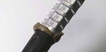
Crimping on a cable lug always starts on the connection side and works towards the cable side. On a connector (splice), however, the first crimp is in the centre. Otherwise, the material cannot elongate and cracks can develop.
With compression cable lugs, for example, the number of required crimps according to DIN 46235 is indicated by marks on the cable lug and connector. With tubular cable lugs, the number of crimps can be checked in the catalogue.
Be sure to complete the crimping process. A complete crimp is important, since the crimped material achieves the required compression only towards the end of the crimping phase. This is the only way to guarantee a correct crimp.
MECHANICAL OR HYDRAULIC CRIMPING?
The crimping tool is the key element of any crimping process. No matter whether this is done hydraulically or by muscle power: as the cable lug is crimped, the degree and type of deformation is defined by the tool or the contact-specific wear parts of the press. Only tools optimally matched in terms of contact create a high-quality connection.
Whether a mechanical press or an electro-hydraulic press is the right choice for you depends on your field of application.
Compact mechanical crimping tools are suitable for small to medium cross-sections. For larger cross-sections, on the other hand, you should generally go for a hydraulic tool with interchangeable dies. You should also consider the number of crimps. Indeed, hydraulic tools are more suited to larger quantities than mechanical ones. Klauke mechanical crimping tools are set apart by synchronous profile dies, which can be conveniently set parallel on both sides in a single-handed operation. In addition, the adjusting wheel indicates the suitable cross-section. This significantly reduces the amount of effort required.
Although for small and simple crimps, you can apply sufficient pressure using mechanical pliers, large conductors are now crimped by electro-hydraulic presses as standard.
Also, the latest generation of electro-hydraulic tools warns optically and acoustically if the required crimp pressure is not reached. High-quality mechanical crimping tools have integrated mechanisms to guarantee a complete crimp.


Class 1
Solid conductor
n Compression cable lugs to DIN 46235 for crimped connections of single, multi, fine or superfine stranded copper conductors
n Standard tubular cable lugs made from electrolytic copper (EN 13600) primarily for multi-stranded copper conductors
n Solderless terminals to DIN 46234 for crimp connections of single, multi, fine or superfine stranded copper conductors
Class 2
Multi-stranded conductor
Class 5
Fine-stranded conductor
n Selecting the correct cable lug hinges on the conductor class to be processed and the customer requirements.
A broad range of cable lugs is available for the most diverse applications in the electrical sector. Making the right choice can be more difficult than you think. However, selecting the correct cable lug is the key to a clean and reliable crimping result. This overview shows the most common cable lugs for copper conductors. We will explain what to bear in mind as you make your choice to ensure a highly reliable and durable connection.
Class 6
Superfine-stranded conductor
Cable lugs for copper connectors, which are connected to the conductor by means of so-called cold deformation, are among the most common connectors in electrotechnology.
They can be generally divided into three groups:
n Compression cable lugs to DIN 46235
n Tubular cable lugs as commercially-available standard versions
n Solderless terminals to DIN 46234

2.1
CABLE AND CABLE LUG: A PERFECT PAIR
Selecting the correct cable lug also depends on the conductor class to be processed. For example, we offer the following cable lug types for cables to DIN EN 60228: n Class 1, 2, 5 and 6 conductors: Compression cable lugs to DIN 46235
n Class 2 conductors: Tubular cable lugs standard type n Class 2, 5 and 6 conductors: Solderless terminals to DIN 46234
To ensure the reliable crimping of conductors with DIN compression cable lugs, the standard recommends crimping tools with die codes to DIN 48083 Part 4. In the case of tubular cable lugs, the specifications of the manufacturer concerned must be observed.
Solderless terminals to DIN 46234 are processed by an indent crimp.
2.2
COMPRESSION CABLE
LUGS TO DIN 46235: WITH FORMATIVE INFORMATION
DIN 46235 defines the fields of application, dimensions and the marking of compression cable lugs. Compression cable lugs to this standard can be used for single, multi, fine and superfine stranded conductors. The structure of the conductor is defined in DIN EN 60228 (IEC 60228). Previously, the conductor structure was described in VDE 0295. Moreover, copper cables to DIN 48201 Part 1 can be processed with these cable lugs. During processing, sector-shaped conductors must be prerounded using the correct tool. Pre-rounding dies with the suitable sector-shaped sleeves, for example.


The markings on the product provide useful information on the origin and use of the compression cable lug - the same also applies for tubular cable lugs. Stamp »KL 20 12 - 120«, for example, means:
n KL: Manufacturer code (in this case Klauke)
n 20: Tool code (only for cable lugs to DIN 46235)
n 12: Standardised metric bolt dimension for the connecting bolt – in this case, M12 bolts
n 120: Intended conductor cross-section in mm²
Compression cable lugs also have markings which provide information on the number and width of the crimps. For processing, the standard recommends hexagonal crimping dies to DIN 48083, Part 4. This standard describes the dimensions of the hexagon crimp form. So you can be sure the connection fully satisfies the DIN standard. The conductor cross-sections of compression cable lugs ranges from 6 mm² to 1000 mm², the hole diameter for the connecting bolt is between M5 and M20.
Compression cable lugs are produced from electrolytic copper: A copper tube is formed by shaping and trimming sheet material. To protect from corrosion, compression cable lugs are tin-plated as standard – the same for tubular cable lugs and solderless terminals. Bright versions are also available. The corresponding compression joint is defined in DIN 46267 Part 1. The properties and processes, are, however identical.
2.3
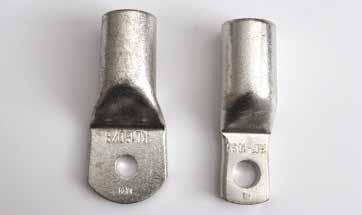
TUBULAR CABLE LUGS: A CLASSIC IN THE STANDARD VERSION
More commonly used than the DIN compression cable lugs are the so-called standard tubular cable lugs. These are also made from electrolytic copper and are offered by various manufacturers. Tubular cable lugs have different dimensions and lengths to DIN cable lugs - as a rule, they are shorter than DIN compression cable lugs and have different tube dimensions.
However, the shorter tube has no negative impact on the durability of the electrical and mechanical connection. Due to the modified tube dimensions, it is not generally possible to process all conductor classes to DIN EN 60228. With hexagonal crimping, only multi-stranded conductors can usually be processed with the tubular cable lug. This is down to the properties of fine-stranded conductors. With indent-like crimp profiles, it is also possible to crimp fine-stranded conductors. Other crimp profiles can be used, and these will be described in more detail in the chapter called “Crimp profiles at a glance”. Multi-stranded, sector-shaped conductors can, of course, also be processed in these cable lugs. This requires the conductor to be pre-rounded with the appropriate sleeves and round crimping dies. Unlike DIN compression cable lugs, the advantage of the tubular cable lug lies in the manufacturing costs. Less copper is required for tubular cable lugs, and this is reflected in the procurement costs.

Image 8: Comparison of

Image 9: Comparison of the most


Unlike DIN compression cable lugs, tubular cable lugs have no crimp markings due to the various crimp profiles. The required number of crimps can be obtained from the relevant manufacturer. With Klauke, you can find the required number of crimps in the technical appendix in the catalogue, for example. Of course, the tubular cable lug is also available as 45° and 90° angled versions and as connectors with the same properties in processing.

10:


2.4
SOLDERLESS TERMINAL TO DIN 46234: FOR CONTROL CABINETS, ETC.
Even solderless terminals to DIN 46234 have to meet the requirements of the standard in terms of application, dimensions and marking. Solderless terminals are used for crimping with multi, fine and superfine stranded conductors. However, solderless terminals to DIN 46234 are not suitable for singlestranded solid conductors - unlike compression cable lugs to DIN 46235.
The conductor cross-sections of solderless terminals to DIN range from 0.5 mm² to 240 mm², the bore diameter for the connecting bolt from M2 to M16. Solderless terminals are used, for example, in control cabinet construction or in the construction of rail vehicles.
Just like compression and tubular cable lugs, solderless terminals essentially consist of electrolytic copper. For production, however, a different source material is used: while compression cable lugs are manufactured from tubes, solderless terminals are made from copper sheets. So by virtue of their design, rounded and soldered from a metal sheet, they have a distinctive soldered joint.
The quality of the soldered joint is key to the crimp result. Poor-quality soldered joints carry the risk of opening during the crimping process. Unlike the compression cable lug to DIN 46235, solderless terminals are not processed by hexagonal crimping, but instead by indent crimping. Klauke offers various tools for this purpose. The recommended tools can be found in the catalogue at the end of each chapter.
2.5 QUALITY AND DURABILITY: ON THE TEST BENCH
The electrical and mechanical properties of cable lugs also have to comply with standards. In this case, IEC 61238 Part 1. This international standard specifies the tests an electrical connection has to pass for continuous, reliable operation in the intended application.
The electrical connections must therefore undergo various tests. In addition to a mechanical tensile test, an electrical durability test is also specified. A test cycle simulates practical application. The connection is heated by electricity 1000 times to approx. 120 °C to induce artificial ageing. Between these tests, the transition resistance is checked at regular intervals. Six high-current tests, during which the conductor is heated to approx. 250°C in one second via a short circuit, are also carried out. This high-current test is specified whenever the connector has to be certified as short-circuit resistant. Klauke connectors have passed this test too. The crimped connection has passed the test if the transition resistance has remained constant throughout.
Manufacturers are responsible for guaranteeing the reliability of their connections. These additional tests are your assurance that our connectors satisfy the highest demands. In addition, many of our connectors have also been tested and certified by the UL (Underwriter's Laboratories). This is particularly useful when control cabinets are to be supplied to North America, for example.
However, we set requirements for the quality of our products beyond the normative standards. Klauke cable lugs are annealed in an additional production step. This allows us to reduce the hardening and stresses in the connector and reduce the risk of breakage during the crimping process.
The quality of cable lugs is evident even from optical features. Burr-free production and a consistently flat palm are signs of a high-quality product – likewise clean final machining of the tube section.


n F cable lugs for fine and superfine stranded conductors simplify the insertion of Class 5 and 6 spliced conductors to DIN EN 60288.
n Tubular cable lugs for single-stranded conductors are set apart by an adapted tube diameter
n Tubular cable lugs for control cabinet connections have a much narrower palm
n Stainless steel tubular cable lugs are especially suited to use in aggressive environmental conditions
n Nickel tubular cable lugs are suited to use in very high temperatures
Many electrical engineers will be familiar with the problem of not being able to use standard cable lugs because they do not exactly match the conductors, for example. The attempt to push a fine or superfine stranded conductor into a cable lug presents this problem: The cable strands splay and the strands do not enter the cable lug correctly. To prevent such annoying situations from the outset, Klauke offers a broad range of special cable lugs. If you can’t find a solution in our catalogue, speak to us.
These special cable lugs can be used to connect all conductor classes without a problem. Their design is geared towards the special properties of the various classes of conductors defined in DIN EN 60228. These are as follows:
n Round single-stranded conductors (re), Class 1 (also known as solid conductors)
n Round multi-stranded conductors (rm), Class 2 n Fine-stranded conductors, Class 5 (also designated as a flexible conductor)
n Fine-stranded conductors, class 6 (also referred to as highly-flexible conductors)
3.1
F CABLE LUGS: IDEAL SOLUTION FOR FINE AND SUPERFINE STRANDED CONDUCTORS
The use of “F” series tubular cable lugs can prevent the common problems of inserting Class 5 and 6 fine and superfine stranded conductors to DIN EN 60228. These lugs are suitable, for instance, for processing larger conductor cross-sections in control cabinet construction, in galvanising plants or for use in rail vehicles.
F cable lugs have a larger tube diameter than standard cable lugs. Also, they are widened into a bell shape in a complex manufacturing process to guarantee better cable insertion. So F tubular cable lugs allow the conductor to be inserted easily and reliable.
Of course, this also has safety-related effects: cross-section tapering due to kinked or un-inserted strands is prevented, and so the full cross section of the conductor is retained.
F cable lugs also have markings. These are as follows: stamping »710F12 K12-150f« stands for
n K: Manufacturer code (in this case Klauke)
n 12: Metric bolt dimension of the bore for the connecting bolt (in this case M12 bolt)
n 150: Conductor cross-section in mm²
n f: “F” series tubular cable lug (fine stranded)
n 710F12: Cable lug item number
Indent and quad-point indent crimping or notch crimping with suitable tools is the ideal solution for achieving a professional crimping process for F cable lugs.
Suitable for the “F” series of tubular cable lugs, Klauke also offer joints for conductor extensions or for repair purposes. The recommended crimping methods are the same as those for F tubular cable lugs. “F” series cable lugs and joints consist of electrolytic copper tube.


To guarantee protection from corrosion, these cable lug types are also tin-plated. The commercially-available conductor crosssections are between 10 mm² and 300 mm². In addition to the straight versions, 45° or 90° angled versions, as well as models with an inspection hole, which conveniently shows whether the conductor has been fully inserted in the cable lug, are likewise available.
Klauke cable lugs are annealed in a special manufacturing process. Stresses are removed from the connector and the risk of breakage is significantly reduced, thereby increasing reliability.
3.2

TUBULAR CABLE LUGS FOR FINE-STRANDED CONDUCTORS (RE)
Class 1 single-stranded conductors to DIN EN 60228 can be best crimped with “E” series tubular cable lugs (cable lugs for solid conductors). These are also made from tinplated electrolytic copper. These cable lugs have an adapted tube diameter, which guarantees optimum crimping of solid conductors. The fields of application include those involving solid single stands, in transformer or engine construction for example. For these cable lugs, we recommend two-point indent and hexagonal crimping.
Tubular cable lugs for single-stranded conductors are recognised by their smaller diameter and also by their marking: The stamping ends with an “E” for “eindrähtig”, the German for “single-stranded”. For example: KL 10 50 E.
For “E” series tubular cable lugs, there are suitable joint and T- and cross-connectors with matching inside diameters for single-stranded conductors.
3.3 TUBULAR CABLE LUGS FOR NARROW SWITCHGEAR CONNECTIONS
In control cabinet construction, installation engineers face several challenges. Aside from the fact that confined spaces usually hamper progress anyway, connecting conductors to powerful switchgear proves especially tricky – from a certain conductor cross-section onwards, conventional tubular cable lugs do not fit into connecting terminal provided. For these difficult applications, special tubular cable lugs for switchgear connections have been developed (“SG cable lugs”). They have a much narrower palm which is readily compatible with the switch gear connection.
The palm of these cable lugs is not only much narrower than that of a conventional cable lug, it is also slightly thicker. This is down to the production process, which uses the same amount of electrolytic copper as for a conventional tubular cable lug.
This tubular cable lug profile is therefore best suited for use in control cabinet construction. They can be processed in exactly the same way as the “standard” cable lug. Suitable crimp profiles would be the hexagonal crimp, the indent crimp or the notch crimp.
The bores are adapted to the dimensions of connecting terminals of standard switchgear. Here too, there are versions with a practical inspection hole.
We strongly advise against cutting off the palm sides of standard tubular cable lugs to make it fit into the connecting terminal of the switchgear. Such manipulations can be highly dangerous. In the worst case, there is the risk of fire due to the reduced cable lug cross-section.


3.4
STAINLESS STEEL AND NICKELTUBULAR CABLE LUGS FOR AGGRESSIVE OR HIGH-TEMPERATURE ENVIRONMENTS
Hostile environments likewise call for special cable lugs. Tubular cable lugs from stainless steel and nickel withstand most conditions and are the ideal solution for crimping copper conductors.
Stainless steel tubular cable lugs are extremely acid and corrosion resistant, and hence especially suited to use in the chemical and foodstuffs industries or for sectors where connectors are exposed to seawater.
Stainless steel is not only highly resistant to acids, it can also withstand high temperatures. Stainless steel cable lugs can therefore be used at ambient temperatures of up to 400°C without a problem.
When the going gets even hotter and cable lugs for particularly high temperatures are required, for example in the hightemperature sector of annealing or heating furnaces, nickel tubular cable lugs are the answer. These lugs are able to withstand temperatures of up to 650°C.
Stainless steel and nickel tubular cable lugs are suitable for Class 2 and 5 fine-stranded conductors, and also for prerounded sector-shaped conductors.
For cable lugs of these resistant materials, we recommend the indent crimp, likewise for the corresponding joint with butt mark.


n The advantage of aluminium conductors: low weight and comparatively simple handling.
n There are four different types of aluminium conductor, some of which require special processing methods.
n Contact grease in aluminium connectors improves the contact properties and achieves a faultless electrical connection.
While special cable lugs provide perfect connections even under harsh conditions, certain circumstances do call for especially lightweight material. Aluminium cable lugs are set apart by their low weight. Aluminium, though, requires much more careful processing than copper: bear in mind that aluminium is less conductive.
Aluminium is being used in an increasing number of sectors. In energy distribution, for instance. Due to the low weight, ductility and the resultant simple handling of cables, distribution system operators are using aluminium cables with increasing regularity - in ring mains for municipal supplies, for example.
Aluminium compression cable lugs with tube dimensions to DIN 46329 and aluminium connectors with tube dimensions corresponding to DIN 46267 Part 2 are a good choice for processing aluminium conductors. All standard aluminium compression cable lugs and connectors with a tube are compatible with single and multi-stranded round and sectorshaped conductors to DIN EN 60228 and with aluminium conductor cables to DIN EN 50182. Compression cable lugs and connectors are not designed for fine and superfine stranded conductors, as these conductor types are not standardised.
A constant material thickness, exact diameter and a precise fit turn aluminium connectors into stable and safe connectors.
Aluminium compression cable lugs are produced with a barrier in accordance with DIN 46329 – allowing even oil-impregnated and paper-insulated cable to be processed without any oil leakage.
However, there are also simpler variants, which are produced from one tube and hence have no barrier. The quality of the connection is the same in both cases. The tube dimensions, however, are based on DIN 46329. The same crimping dies, therefore, can always be used.
ALUMINIUM CONDUCTORS AT A GLANCE
Aluminium conductors are offered in four different variants, some of which call for special processing methods:
n Single-stranded pre-rounded conductors, class 1 (re)
n Single-stranded sector-shaped conductors, class 1 (se)
n Multi-stranded pre-rounded conductors, class 2 (rm)
n Multi-stranded sector-shaped conductors, class 2 (sm)
The abbreviations along with other information can be found on the connectors and cable lugs. These show which aluminium conductor is suitable for which connector or cable lug.
The markings on the aluminium compression cable lugs generally correspond to those found on copper cable lugs. For example: »KL22 12-120 rm/ sm 150 re/se«
n KL: Manufacturer code (in this case Klauke)
n 22: Tool code
n 12: Metric bolt dimensions of the connecting bolt bore (in this case M12 bolt)
n 120: Conductor cross-section in mm² (rm/sm)
n rm/sm: For multi-stranded round conductors and multistranded pre-rounded sector-shaped conductors
n 150: Conductor cross-section in mm² (re/se)
n re/se: For single-stranded round conductors and singlestranded pre-rounded sector-shaped conductors
You may have noticed that the nominal cross-section of the se and re conductors are always one unit higher than the nominal cross-section of the sm and rm conductors. The reason is quite simple: single-stranded conductors take up less volume than multi-stranded conductors. To obtain a reliable connection, we recommend hexagonal crimping dies to DIN 48083 Part 4 or the indent crimping tool EKM60ID for processing of compression cable lugs.
Class 1
Single-stranded round conductor (re)
Class 1
Single-stranded sector-shaped conductor (se)


For aluminium, there are special crimping dies which, with a crimping width of 7mm, are 2mm wider than the crimping dies for copper connectors. The larger crimping widths create a larger contact surface, which compensates for the low conductivity of aluminium.
CONTACT GREASE FOR ALUMINIUM CONNECTORS
Commercially-available connectors for aluminium conductors are supplied with a special contact grease. During the crimping process, this destroys the non-conductive oxide layer of the aluminium, which forms on the surface after just a short time. The grease improves contact properties. The grease also prevents re-oxidisation of the contact points. The result is a faultless electrical connection. Most cable lugs are sealed with a plastic plug, which prevents the contact grease from drying out or running out and extends the shelf life of the grease.
Contact grease for aluminium connectors consists of corundum, a sand-like mineral set apart by its high wear and corrosion resistance even at high temperatures. During the crimping process, an emery effect wears and destroys the oxide layer. The grease also improves the sliding friction between conductor and sleeve. With multi-stranded conductors, the grease is distributed during the crimping process between the single strands and seals them – thereby preventing the ingress of oxygen and moisture.
Another huge advantage is that aluminium compression connectors with contact grease can withstand higher current loads than if no contact grease is added. We therefore recommend the use of cable lugs and connectors with contact grease – play it safe with a high cable conductor utilisation.
STEP BY STEP: THE PROCESSING OF ALUMINIUM COMPRESSION CABLE LUGS AND CONNECTORS
Aluminium has special properties and a precise processing procedure is therefore a must. Ideally, proceed as follows to make a clean connection:
1. Remove the insulation from the aluminium conductor.
2. Carefully treat the bright end of the conductor with a blade or wire brush for example, to coarsely remove the oxide layer and produce a clean contact surface. Make absolutely sure that that no metal traces remain on the conductor after cleaning, as this could lead to contact corrosion.
3. Insert the conductor into the cable lug or connector to the full insertion length of the sleeve. The contact grease will flow out to the side, thereby creating an air seal which prevents re-oxidisation.
4. You can now make the hexagonal or indent crimp using the suitable tool. Before the actual crimping process, a single or multi-stranded sector-shaped conductor must be prerounded using a suitable round crimping die.
5. Finally remove the discharged contact grease. Aluminium cable lugs have alternative markings for narrow and wide crimps. The advantage of the wide variant is that the number of crimps required is halved. However, note that a correspondingly powerful crimping tool should be used.
With sector-shaped conductors, you can use Klauke prerounded dies. Unlike with copper conductors, sleeves cannot be used with multi-stranded sector-shaped conductors.


n The combination of aluminium and copper is problematic.
n High-quality Al/Cu compression cable lugs are suitable for connecting aluminium conductors to copper.
n Contact grease with aluminium connectors improves the contact properties.
n Aluminium/copper connectors are required for a professional connection between aluminium and copper conductors.
We will now concentrate on the connection between aluminium and copper, which is not exactly simple. As already mentioned, aluminium is now used quite often, but not always by itself. Since copper has been the material of choice for decades and is still being used, reliably connecting the two materials presents a problem. In practice, electrical engineers are facing this challenge with increasing regularity.
The connection between aluminium and copper is required more often than would appear at first glance. As an example, this is required when an industrial area has an aluminium ring main, but the supply to the adjacent operations is via copper conductors. In transformer stations too, there are times when aluminium conductors have to be connected to copper rails.
Electrical engineers face the problem that aluminium and copper cannot be readily connected to each other. For a lasting, reliable connection, you should therefore use special Al/Cu copper cable lugs and connectors.
ALUMINIUM/COPPER: A SPECIAL CONNECTION
In practical use, aluminium appears to be resistant against corrosion. However, aluminium is a highly-reactive and readilyoxidising material. The material’s durability is down to a resistant oxide layer, which forms on its surface in the presence of atmospheric oxygen – also known as self-passivation.
If an electrically-conductive liquid such as condensate reaches an aluminium and copper connection, an electrochemical reaction occurs and causes contact element formation.
The potential differences caused by the electrochemical series play a key role in this process. The contact element is formed by the copper electrodes (anode), the electrolytes (water) and the aluminium electrodes (cathode).
The voltage generated as a result is short-circuited by the contact between copper and aluminium. As a result of the current flow, the aluminium deposits or decomposes. This process is visible as a blooming oxidation spot and starts when even the smallest copper particles come into contact with the aluminium – specifically, as a permanent reaction, since copper does not decompose. An electrical connection increases the transition resistance, which can lead to a temperature rise and a fire in the worst case.
When joining copper and aluminium, therefore, you should prevent the influx of moisture at the junction of the two materials at all costs. In rooms where condensate forms, the point of contact between copper and aluminium must therefore be protected by means of special processing methods.
The use of Al/Cu copper cable lugs and connectors is the most important step here. These have no so-called creepage path where the conductive fluid produced by the oxidation process can accumulate. As a result, Al/Cu compression cable lugs and connectors are also especially suited to use in offshore wind farms. Tin-plated aluminium cable lugs can also be used. This solution should be used only in rooms that are constantly dry, since even minor damage to the tin layer can initiate contact corrosion.
5.1 AL/CU COMPRESSION CABLE LUGS
Compression cable lugs developed specifically for connecting aluminium conductors and copper rail consist in the crimping area of electrolytic aluminium (E-Al) and an attached screw-on palm to EN 13600.


ALUMINIUM CONDUCTORS AT A GLANCE
According to DIN EN 60228, there are four different variants of aluminium conductors, some of which call for special processing methods. Available conductors are:
n Single-stranded round conductors, class 1 (re)
n Single-stranded sector-shaped conductors, class 1 (se)
n Multi-stranded round conductors, class 2 (rm)
n Multi-stranded sector-shaped conductors, class 2 (sm)
The abbreviations along with other information can be found at the markings on the Al/Cu compression cable lugs. This tells you which aluminium conductor is suitable for the respective cable lug.
Stamping »8 KL16 50 rm 70 se« stands for


n 8: Metric bolt dimension of the bore for the connecting bolt (in this case M8 bolt)
n KL: Manufacturer code (in this case Klauke)
n 16: Tool code
n 50 rm/sm: Nominal conductor cross-section in mm² for use with a round or sector-shaped multi-stranded conductor
n 70 re/se: Nominal conductor cross-section in mm² for use with a round or sector-shaped single-stranded conductor
For crimping Al/Cu compression cable lugs, we recommend the use of hexagonal crimping dies to DIN 48083 Part 4 or EKM60ID.
Incidentally, Klauke aluminium crimping dies are silver-coloured, copper dies are golden yellow – so they are very easy to differentiate.
5.2 AL/CU CONNECTORS: RELIABLY JOINED
For a reliable connection of aluminium and copper conductors, Klauke offers reducing connectors.
Reducing connectors are often used for grid reconstruction, more precisely to produce stress-relieved connections between aluminium conductors to DIN EN 60228 and copper conductors to DIN EN 60228. The connectors are produced from two components: aluminium (E-Al) and copper parts (to EN 13600). As a rule the aluminium side has a larger diameter, since the low conductivity is compensated by the correspondingly high nominal cross-section.
As with compression cable lugs, the aluminium side of the connector also contains contact grease, which is prevented from running out and drying out by a protective cap.
When processing Al/Cu compression connectors, follow to the corresponding processing instructions for copper and aluminium to obtain reliable results.
When using compression connectors underground, be sure to protect the joints from moisture. Ideally, use a cast resin joint. The joint permanently protects the connections from moisture, dust and the penetration of foreign bodies.
Finally, an important note on cable lugs and compression connectors made from aluminium and copper: do not expose these products to any bending stresses, as this could cause the contact point of the two materials to break. Use in the overhead line sector is therefore not possible.


6. WELL CRIMPED IS PERFECTLY CONNECTED: OVERVIEW OF CRIMP SHAPES
Hexagonal crimping
The indent crimp for copper and aluminium
The indent crimp for copper and insulated materials
The quad-point indent crimp Sicher ist sicher: Fehlerhafte Verpressungen vermeiden


n Hexagonal crimping is the most common method of crimping cable lugs and connectors.
n Indent crimping produces a lasting, reliable and and deep-penetrating connection.
n The benefits of quad-point crimping lie in the central force application and the simple processing.
n The notch crimp: well-tried and proven
Once we have explained which cable lug matches which application, we will take a look at the various crimp profiles.
This might appear complicated at first glance, but a second look shows that this is not the case.
Every day, electrical engineers are confronted with a host of different conductor types, each of which calls for different cable lugs and connectors to ensure professional processing. Once matching components have been selected, the question is, which crimp profile is most likely to produce a reliable connection. The most suitable crimp profile depends on material, design and application.
6.1 FOR ALUMINIUM AND COPPER: HEXAGONAL CRIMPING TO DIN 48083
PART 4
Hexagonal crimping is among the conventional crimp profiles. It is the most frequently used in practice, as it is suitable for both copper and aluminium conductors. In this crimp profile, the individual strands are deformed over a large horizontal area.
Hexagonal crimping is typically used for copper compression cable lugs to DIN 46235 and aluminium compression cable lugs to DIN 46329. This crimp profile can also be used to crimp solid cables.
The clear benefit of hexagonal crimping is in the central force application during the crimping process, which occurs uniformly from all sides and hence acts on a large contact surface. At the same time, the individual strands of the conductor as a whole are uniformly deformed without being damaged.
The result is good mechanical stability and a reliable connection. Thanks to the uniform crimping, hexagonal crimping is also suitable for the medium and high voltage sector.
THE ALTERNATIVE: MANUFACTURER-DEPENDENT HEXAGONAL CRIMPING
In addition to standardised hexagonal crimping, so called manufacturer-dependent hexagonal crimps are also permissible for copper applications in conductor classes to DIN 60228 Class 2. They are developed specifically for the tubular cable lugs offered. Therefore, it is very important that one manufacturer-specific system is always used.
FREEDOM OF CHOICE: WIDE OR NARROW CRIMP
You can use narrow or wide crimping, depending on the tool. This depends largely on cross-section and the tool force. Narrow crimping, for example, is suitable for a 300 mm² tubular cable lug with a six tonne battery-powered hydraulic tool. However, this requires multiple crimps, which of course involves additional time. The purchase of a tool must therefore be carefully selected and matched to the range of applications.


6.2


THE INDENT CRIMP: FOR COPPER AND ALUMINIUM
The indent crimp is one of the few crimp profiles that require no cross-section-dependant crimping dies. For example, the Klauke EKM 60 ID an process a crimping range of 10-240 mm² for copper and 50-240 mm² for aluminium. This is made possible by two technical innovations. First, the hydraulic cylinder is a single-acting 2-stage telescopic cylinder. Due to the differing piston diameters and the patented design of the two hydraulic cylinders, the crimping head produces twice the force at the start through the larger hydraulic cylinder, than it does at the end when only the smaller hydraulic cylinder is working. Consequently, the larger cross-sections are processed with a greater force than the smaller ones. This guarantees that all cross-sections are crimped with adequate force and smaller cross-sections are not damaged by excessive force. indent is a special profile, which is matched to the respective diameter of the cross-sections.
As well as needing fewer dies, this has an added advantage for the user. This crimp profile can be used to process even very thinned-out or compacted conductors. This is because the device switches off only after the required degree of compaction is achieved. This profile is also capable of processing tubular cable lugs, tubular cable lugs for fine and superfine stranded conductors, solderless terminals and aluminium cable lugs. Fine-stranded conductors in tubular cable lugs are also possible.
Tubular cable lugs and aluminium cable lugs require the same number of crimps as wide crimping due to the properties. When processing aluminium cable lugs, it must be ensured that the tool is positioned offset by 180° for every crimp. Otherwise, the aluminium cable lug can become deformed. With solderless terminals, the soldered joint must always be crimped once. With tubular cable lugs for fine-stranded conductors, it is necessary to crimp once up to 185 mm² and twice from 240 mm².
ADVANTAGES OF INDENT CRIMPING AT A GLANCE n Reliable: it is not possible to mix up or mismatch the dies. n Flexible: the crimp profile can be used flexibly for various conductor classes and is especially suitable for thinned-out or compacted conductors.
n Cost-effective: no additional purchase of dies required.
6.3 THE INDENT CRIMP: FOR COPPER AND INSULATED MATERIALS
The indent crimp was developed for producing connections with cable lugs to DIN 46234 and connectors to DIN 46341 Part 1, profiles A+B, which are in turn suitable for mounting Class 2, 5 and 6 conductors to DIN EN 60228.
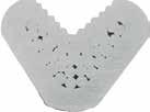
To be able to cover all conductor classes without a problem, cable lugs and connectors to these standards have a large internal diameter. Indent crimps deform the individual strands so as to make very good electrical and mechanical contact.
The indent crimp has a cross-section that resembles a halfmoon. This crimp can also be described as deep indent, which allows the conductor strands to move and form a solid compression. Despite the large internal diameter, a permanent, compact and reliable connection can be guaranteed thanks to the centered bundling of the strands.
This crimp profile is particularly suited for tubular cable lugs, solderless terminals to DIN 46234 with and without insulation and cable lugs for fine-stranded conductors. Although the indent crimp is a non-standardised crimp profile, it is nonetheless used for standardised cable lugs. Hence: make absolutely sure that the materials and crimping tools are compatible. Otherwise there is a risk of individual strands becoming crushed, which can impair the mechanical and electrical properties.


Image 8: Indent crimp from above and below

Image 9:

Image 10:

11:
6.4


THE QUAD-POINT CRIMP: FOR COPPER
The quad-point crimp found its way into German control cabinet construction from the USA. In this sector, it is used up to 1 kV. However, it has also proved useful for other connections too, in locomotive drive units for example. This crimp profile is suitable for tubular cable lugs and connectors with cross-sections from 10 mm² to 300 mm² in combination with conductor types to EN 60228, Classes 2, 5 and 6.
The advantage of the quad-indent crimp over a standard indent crimp is the centric force and the simple processing, which does not require different dies. You can process all sizes in the cross-sectional range above using just one crimping tool –this is extremely practical. The quality of the crimp therefore depends on the effort required and the tool used. However, the quad-point indent crimp is not suitable for insulated connectors, the indents can damage the insulation.
6.5
THE NOTCH CRIMP: WELL-TRIED AND TESTED

The notch crimp is the oldest and presumably also the original best-known crimp profile in the electrotechnology sector. It is still used in control cabinet construction to 1 kV today. It is set apart by a deep point-specific deformation of the cable lug. However, it is suitable only for processing copper. The deep point-specific deformation may also be why it has fallen out of favour somewhat with the experts, and is being gradually replaced by the generally established hexagonal crimp.
MULTI-PURPOSE IN TWO VARIANTS
In practice, there are two different types of notch crimp: the conventional notch crimp and the two-point indent crimp. Our notching tools are capable of crimps with cross-sections of up to 400 mm².
The two variants have the same effect and have identical properties. All notch crimps are special crimps, which are most suitable for fine and superfine-stranded conductors in order to produce durable and reliable connections. However, they are also able to reliably connect multi-stranded conductors.
The notch crimp can be used to process a broad range of conductors: from Class 2 multi-stranded copper conductors to DIN EN 60228 to Class 5 and 6 fine and superfine stranded types. It must of course be ensured that the appropriate cable lug is used.
From a technical perspective, the notch crimp is set apart mainly by its high degree of compaction. However, be aware that notching causes high material stress, resulting from the strong force applied during the crimping process. Therefore, it is important that high-quality connectors are used and the connection is stress-relieved. The number of notches required is the same as with a narrow hexagonal crimp.
STILL USABLE
In summary, we can say that the notch crimp is a useful, standards-compliant crimping method – primarily for crosssections below 6 mm², but also in control cabinet construction to 1 kV. Never discount the notch crimp – always permitted and efficient as well.
There is no doubt, however, that the acceptance of the notch crimp among experts isn't what it once was. It is therefore important with concrete projects to clarify with customers in advance as to whether they allow notching in their technical facilities and plants.


6.6
SAFE AND SECURE: AVOIDING FAULTY CRIMPS
The reliability and hence the quality of a cable connection is guaranteed to the extent required only if the crimping process is carried out to optimum effect. The prerequisites are use of the correct tool and the correct cable lug. It is also essential, however, that crimping die and cable lug are perfectly matched. If not, an under-crimp or over-crimp can be the result. Both of these faulty crimps can have a huge impact on safety.
An under-crimp occurs if the crimping die is too big for the cable lug. One example of this would be the processing of a tubular cable lug by a compression cable lug die for cable lugs in accordance with DIN 46235. Due to the larger wall thickness and diameter of the compression cable lug in accordance with DIN 46235, this crimping die has a diameter that would be too large for the tubular cable lug. When this crimping die/cable lug combination is used, the cable lug is not adequately formed. An under-crimp can also occur if the tool used was unable to apply the required force and, as a result, failed to close correctly during the crimping process. The mechanical, and hence also the electrical connection is not completely made. You can recognise this kind of under-crimp by the almost round tubular cable lug and the weak embossing of the designation. The designation is generally a good indicator of whether the correct crimping die was used. In the case of tubular cable lugs, the embossed cross-section in the hexagon must match the cross-section data on the palm. The same applies to the code numbers on DIN compression cable lugs.
An over-crimp occurs if the crimping die is too small for the cable lug. One example of this would be the use of a crimping die for tubular cable lugs in combination with a compression cable lug in accordance with DIN 46235. The result is a sharp flash, which presents an injury hazard and which can cut open the heat shrink tubing. When the flash is cut off, a reduced cross-section occurs, and this must likewise be avoided. Moreover, the conductor strands can be damaged by the high force effect.
In case of doubt, we recommend replacing the connection as non-destructive testing of the connection is very difficult.
Essentially, all faulty crimps carry a safety risk and constitute a hazard potential that should not be underestimated. To solve the problem, it is always advisable to use a system that has been tested by the manufacturer. In addition, clear instructions for working with cable lugs, crimping dies and tools must be available and used as a guide. In case of uncertainty – when choosing the correct crimping die, for example – you should always consider contacting the manufacturer.
The Klauke catalogue contains, at the end of each connection technology section, a table showing the tool recommendations that you can use as initial support. If you have any other questions, our applications engineers are on hand to provide advice and support.


Cable end-sleeves are defined in DIN 46228. In this article, we refer to cable end-sleeves in accordance with DIN 46228-1 (cable end-sleeves without plastic sleeve) and in accordance with DIN 46228-4 (cable end-sleeves with plastic sleeve). For the most part, the information applies also to the cable end-sleeves for short-circuit proof conductors and twin cable end-sleeves. However, as these components are not standardised, the dimensions may differ from manufacturer to manufacturer. Standards DIN 46228-1 and DIN 46228-4 define only cable end-sleeves from 0.5 to 50 mm2. The standard does not apply to any sizes outside of this range and the dimensions can, theoretically, be freely selected by the manufacturer. Standards DIN 46228-2 and DIN 46228-3 set out the requirements for non-connected cable end-sleeves, which have to be bent together during a crimping process. However, these cable end-sleeves are not the subject matter of this article.
Due to the lack of standardisation, there is a diverse range of cable end-sleeves in this sector and this makes the correct choice of tool all the more important. The aforementioned standards define the dimensions, colours, applications and tests for cable end-sleeves. Low cost cable end-sleeves often differ in the hardness of the copper. It may be that low-cost brands are more difficult to process and, ultimately, the crimp does not fulfil requirements. Therefore, high-quality processing is important even with such a simple component.
7.1 PURPOSE
According to the standard, DIN 46228 cable end-sleeves are compatible with multi-stranded, fine-stranded and superfinestranded conductors. Many manufacturers, however, approve the cable end-sleeves only for Class 5 and 6 conductors. This is down to the main function of cable end-sleeves. They are used primarily to prevent the conductor from splaying. However, splaying rarely occurs with Class 2 conductors.
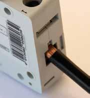
The use of cable end-sleeves makes it easier to insert the conductors into the terminals. It is up to the terminal manufacturer to decide whether a cable end-sleeve has to be used in a terminal or whether such use is optional. We generally recommend the use of cable end-sleeves for all applications. This prevents a multitude of errors and processing is much easier, ultimately saving time and money with assembly. In addition, it is much easier to change the wiring at a later time if cable end-sleeves are used.
7.2
CRIMPING PROFILES AND TOOLS
DIN 46228 specifies neither crimping profiles nor tools. Therefore, any crimping profile is possible in principle, as long as it passes the tests indicated in the next section. Due to the lack of standardisation, a broad range of crimping tools and crimping profiles has developed through the decades. The tools range from simple hand tools through to highly developed hydraulic ones.
When selecting a tool, you should first of all make sure that its quality features guarantee or support consistent crimps. The second key criterion should always be that the tool fits the application. A battery-powered tool, for example, is not necessarily recommended for processing small cross-sections. However, such a tool soon pays for itself when used for the frequent processing of large cross-sections. There is not just one perfect tool for everyone – instead, the tool must always be adapted to the day-to-day challenges.
Generally, any profile that permits the pull-out values of DIN EN 60999-1 and fits into the plug gauges in accordance with DIN EN 60947-1 can be applied. These plug gauges provide the basis for the dimensions of the connection terminals on electrical equipment.
DIN 46228 makes reference to DIN EN 60999-1 for the pull-out values. However, this standard covers only cross-sections up to 35 mm². Klauke therefore applies DIN EN 60999-2 in addition for 50 mm². The generally established range of crimping profiles comprises indent, trapezoidal, square and hexagonal crimps. Indent and trapezoidal crimps are frequently used for tools with predefined crimp inserts. For force-dependent and stroke-dependent tools, on the other hand, square and hexagonal crimps are often used.
The huge advantage of force-dependent and stroke-dependent crimping tools is that accidental use of the incorrect nest is effectively prevented. The square crimping profile offers optimal compression and therefore optimal pull-out values. Creates safe connections in compact terminal blocks.
If you are in any doubt as to whether the crimping profile is compatible with the connection, we would advise asking the terminal manufacturer directly. Ideally, this information should also appear in the operating instructions.


Recently, there has been a lot of talk about “gas-tight crimps”. This expression presents a problem in that there is no standardised test for demonstrating gas tightness. From a technical perspective, the amount of force required to guarantee gas tightness causes the individual conductor strands to become welded together. Otherwise, there is always the possibility of gases entering.
Due to their thin walls, cable end-sleeves are unable to withstand the high forces required. The open design of cable endsleeves also makes it difficult to achieve gas tightness. The expression “gas tight” actually originates from the automotive industry. In automotive applications, front-soldered or directly deep-drawn cable lugs are used, and these are crimped with several tonnes of force. Even these connections are not absolutely gas-tight, although much thicker outside walls and precisely defined conductors are used. In this case, the gas-tightness is defined by internally-specified tests.
The question of whether a “gas-tight” crimp is actually required also arises. No corrosion can occur in places where the copper has made an electrically conductive contact due to cold forming. Even if slight corrosion occurs between the individual strands over time, it will not affect the conductivity of the connection, since there has never been electrically conductive contact at this point. It remains debatable, therefore, whether there is more to the catchphrase “gas-tight crimp” than a marketing argument.
7.3
TESTS
DIN 46228-1 and DIN 46228-4 define two different tests: the

The dimension test serves to ensure that the crimped cable end-sleeve also fits into the connection terminals provided. Here, DIN 46228 makes reference to DIN EN 60947-1. This standard sets out the general specifications for low-voltage switchgear. According to this standard, the crimped cable endsleeve must fit into the plug gauges defined in DIN EN 609471. There are two different profiles. Profile A defines rounded, square connection points and Profile B defines round connection points. Ahead of the test, it is necessary to define whether the cable end-sleeve is to fit into both templates or only into one.
In addition to the tests mentioned in DIN 46228-1 and DIN 46228-4, there are also tests for the North American market, for example. These are defined in UL 486F and CSA-C22.2 No. 291-14 respectively. These two standards have been harmonised and are therefore identical in terms of content. This relates exclusively to one test standard, and therefore only tests, not dimensions, of the cable end-sleeves are specified. There is solely the material specification that the cable end-sleeves are at least 80 % copper and should be tinned. These test standards are somewhat more detailed than DIN 46228-1 and DIN 46228-4. In addition to the pull-out values, they describe a heat-up test followed by a puncture test of the insulation at 1 kV and a flame resistance test. The last two tests, of course, are relevant only for testing cable end-sleeves with insulating collars.
7.4
CONCLUSION

The tensile test furnishes proof of the mechanical connection between conductor and cable end-sleeve. The standard makes reference to DIN EN 60999-1, in which the safety requirements for screw terminals and screwless terminals are described. A cable end-sleeve must withstand the same tensile forces as the bare conductors of a terminal. This also makes sense, since cable end-sleeves are processed almost exclusively in such terminals. The test involves clamping the crimped cable end-sleeves in a towing vehicle. In an axial direction to the cable end-sleeve, a force dependent on the cross-section is then applied at a defined speed until the maximum force is reached. This force must be maintained for one minute. The forces are
Although cable end-sleeves are, theoretically standardised, there are many points to consider in practice. Generally speaking, high-quality material and tools must of course always be ensured. Particularly in the case of cable end-sleeves that are not covered by DIN 46228, it is important to ensure that the tool and cable end-sleeve are compatible. This is most easily done if items come from the same manufacturer. The system specified by the manufacturer should also be used for standardised cable end-sleeves. The UL certification, for example, is valid only if cable end-sleeve and tool are from the listed manufacturer. Should a fault ever occur, purchasing from one manufacturer also offers the benefit of having one permanent contact partner.


8.1
THE BEST TIPS ON HOW TO EFFICIENTLY CUT WIRES
8.2 AUTOMATIC SELFADJUSTMENT INSTEAD OF FIXED BLADE

A clean and straight cut that neither deforms nor damages the wire is of particular importance when working with wiring so as to ensure that safe and dependable connections can be made. Every user has her or his own preferred wire-stripping technique. However, in principle, it is possible to distinguish between two different cutting techniques: shear cutting and wedge-action cutting as it is generally referred to. Both techniques are in accordance with the DIN standard 8588.
In the case of shear cutting, the wire is severed by two cutting edges that move past one another. This technique is used primarily when cables, wires or conductors out of copper or aluminium have to be stripped. High quality wire stripping tools are equipped with an integrated cutting unit that is specially designed for these types of materials. As a result, the cut can be implemented with little effort, efficiently and in a tool-friendly manner.
However, wedge-action cutting is the preferred choice whenever hard metals need to be severed. In this case, the cable is pushed apart by one or two wedge-shaped cutting edges and severed.
For both cutting techniques it is a case of: to ensure fast and safe work, the cutting unit needs to be an optimal fit from an ergonomics point of view.
In everyday, practical situation, cable stripping knives with a fixed blade still continue to be used. Yet for safety reasons, the use of these types of knives should be avoided since the danger of injury is not inconsiderable. Frequently, cable sheath removers or even stripping knives with adjustment screws are used as alternatives – but even these types of cutting tools have significant disadvantages. Since the cross sections of cables and wires cannot be measured and determined physically but are calculated on the basis of the conductance, the cross section value is consequently reduced when leads are severed during the wire stripping process, something that is not uncommon. This may result in contact resistances and, at worst, cable fires.
Such risks can be counteracted when modern and requirementspecific tools are selected. They adjust automatically to the respective cross section and the insulation thickness, enabling an optimum stripping of the cable. Additionally, special pliers have been developed for handling extremely thick and even very thin insulation layers. These tools do not only have the automatic self-adjustment feature, but can also be set manually to the required cross section. This means that the very highest level of safety is guaranteed no matter what the circumstances or requirements may be. However, in the case of extremely thick insulation layers, it is advisable to firstly make a wire-stripping test on a specimen cable.


8.3
SUPERFLUOUS AND HAZARDOUS:
THE SHORTENING OF PROTRUDING LEADS
In practical working processes, the stripping of cables and wires often involves far more effort than is really necessary. After a lead has been stripped and a cable end-sleeve attached and crimped, it is sometimes the case that protruding leads then have to be shortened. Such a subsequent cutting process is not only superfluous, it is also dangerous. There is, for instance, the risk in switching cabinet construction that some of the leads are already connected in existing circuits and consequently cause a short circuit.
It is therefore advisable to use an automatic wire stripping tool that has adjustment settings for the wire stripping length. Optimally, it should feature a combination out of adjustable length stop and a scale that shows both the metric dimensions as well as the inch sizes for AWG cables (American Wire Gauge). One great advantage is that the stop ensures a constant and consistent insulation length.
To enable optimum results to be achieved, the length of wire to be stripped should always represent the length of the sleeve plus 2 mm. Ideally, only 0.05 mm at a maximum should protrude from the sleeve shaft when the cable is inserted into the sleeve. In the case of twin cable end-sleeves, the length of wire to be stripped should always represent the length of the sleeve plus 3 mm – the reason for this being the insertion funnel.
Conventional push-in clamps have a clamping mechanism that is relatively far away from the insertion funnel. In these cases, the best results are achieved when cable end-sleeves with a greater sleeve length are applied. For example, in the case of screw clamps with a cross section of 1.5 mm², cable endsleeves with a sleeve length of 8 mm are used. It is important to strictly observe the manufacturers’ instructions when using push-in clamps. For safety reasons, it is advisable to select a length dimension that is one higher. In other words: a sleeve length of between 10 mm and 12 mm is best suited for a cross section of 1.5 mm².
8.4 TOOLS FOR COMPLEX REQUIREMENTS AND HIGH USER CONVENIENCE
Application-specific cable with high insulation requirements is used in many different sectors. The shipping industry, for instance, places great demands on cables and wires with its international approvals – and in switching cabinets as well as in machinery and equipment construction, halogen-free wiring has long been the standard. To enable good insulation properties to be achieved despite such demanding requirements, insulating material out of PE or TPE is frequently used.
A number of different material properties, from soft to ductile and brittle, all contribute to making the professional stripping of wire a real challenge. The right tool is therefore all the more important to enable the insulation to be perfectly removed. Wire stripping tools by Klauke are equipped with innovative cutting edge features and special blade geometries. The wire stripper K43/2U is designed for cross section ranges of 0.08 mm² to 16 mm² and remove even complex insulating material efficiently and cleanly. Even sheathing material out of silicon or hard insulating substances, as can be found on UL-specified cable types, present no obstacles whatsoever for the Klauke wire strippers. When simply PVC or PVC-similar materials are used, Klauke offers a professional wire stripping tool K43/3 with an extreme cross section range of between 0.08 mm² and 16 mm².
Besides efficiency and safety, a good wire stripping tool should offer one thing in particular: ergonomy. Since every gram counts for the user to enable her/him to work easily over a sustained period, low weight is absolutely vital whenever tools are concerned. Wire stripping operations that have to be carried out several hundred times a day is not uncommon in the switch cabinet construction and engineering areas – and that repre sents a great strain on the hand and arm muscles. Klauke wire stripping tools such as the K43/2U feature outstanding ergo nomics. Their weight of only 140 Gram ensures sustained work and combines this with great convenience.


PVC CABLE
8.5 TOOL SELECTION: QUALITY IS DECISIVE
The selection of the right wire stripping tool should particularly be in focus when wire stripping operations are to be carried out safely. In any case, it is crucial that the tool has a high quality and meets the essential demands placed on flexibility, safety and user convenience: after all, good wire stripping is a precondition for safe and longlasting connections.
Conventional conductor
e.g. PVC insulation
Low tensile strength
Normal insulation thickness
e.g. PVC insulation
Medium tensile strength
Twin conductor with varying insulation thicknesses
PVC CABLE
PVC CABLE


HALOGEN FREE
HALOGEN FREE CABLE
Specially-insulated conductor
e.g. halogen-free, hard and smooth insulation
Medium tensile strength
Normal insulation thickness
SILITHERM
EXTRA STRONG CABLE

Extreme conductor
e.g. extremely smooth Teflon (PTFE) insulation
High tensile strength
Even for large cross sections
