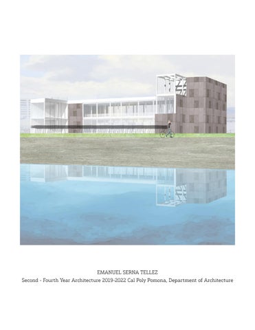
EMANUEL SERNA TELLEZ Second - Fourth Year Architecture 2019-2022 Cal Poly Pomona, Department of Architecture
Emanuel Serna Tellez esernatellez@cpp edu
909 - 358 - 3976
I am a 2023 architectural graduate student from California State Polytechnic University, Pomona. I currently work part-time for a construction drafting company, Zaha Arch Design located in San Bernardino. I am enthusiastic to continue my architectural journey at an architectural firm.
CONTENTS 13 05 23 37 37 37 Veter Mountain Retreat Project Architecture School Tower Project Mixed Used Project in East Hollywood Living Wall for Cal Poly, Pomona Hosfield Preservation Project Urban Winery in Boyle Heights
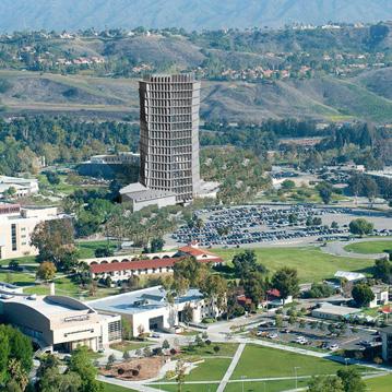
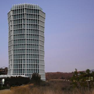
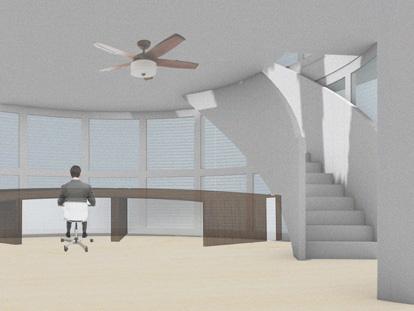
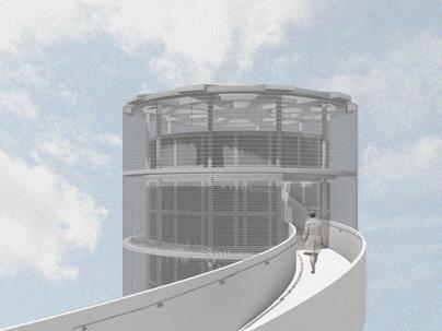
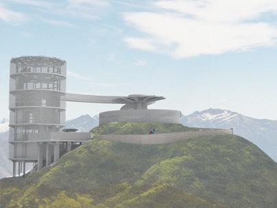
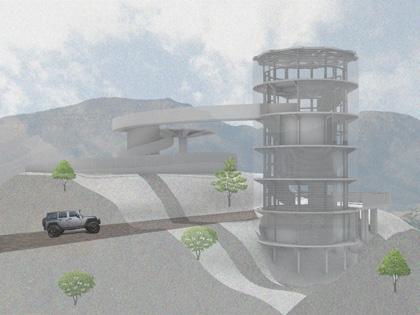
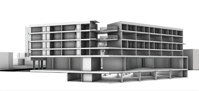
SECOND YEAR ARCHITECTURE SCHOOL TOWER PROJECT
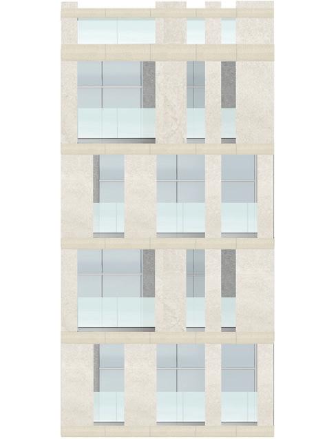
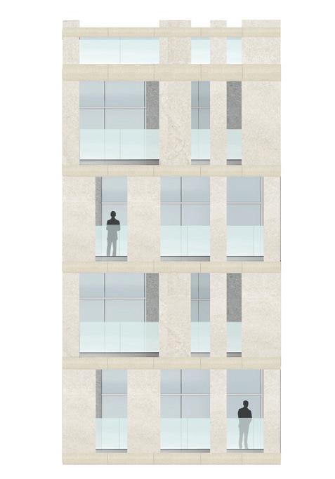
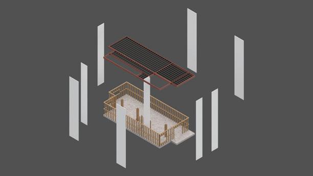
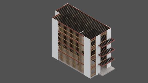
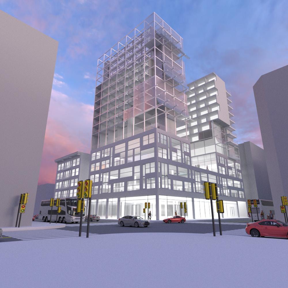
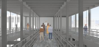
In the last step of finalizing the design, the main focus was to establish a facade. In doing so, the predetermined shape of the plinth and the shape of the octagon were used to create a grid. Through this grid, the tower’s program was organized and the enclosed spaces were created.
Additionally, this organization of the prrogram allowed for double height spaces through out the tower. Furthermore, the idea of using a grid can also be observed on the building’s facade. This idea can be observed in the vertical and horizontal fins around the tower that work as brise-soleil. This brise-soleil takes the shape of a twisted octagon, which takes its shape from the previous phase, and changes in extrusion as it goes around the tower and provides dynamic shadows around. This tower takes advantage of the sun by having the brise-soleil fins spread apart as they go from the south to the north direction in order to take advantage of the sunlight in the north or to provide shade in the south. The top of the tower is opened up and reveals the tower glazing in the north in order to allow for more sunlight to enter the tower. This top opening steps up to cover the tower on the west and east sides of the tower. Lastly, when the brisesoleil reaches the plinth of the tower, it becomes the roof of the plinth which continue to serve as openings to allow natural light into the building.
5 SECOND YEAR | ARCHITECTURE SCHOOL TOWER PROJECT SITE PLAN
6
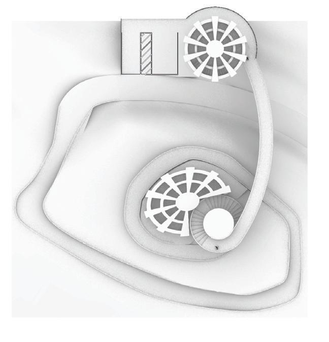
7 SECOND YEAR | ARCHITECTURE SCHOOL TOWER PROJECT A B B A 2 3 4 5 6 7 7 7 GROUND FLOOR PLAN 1. CONSTRUCTION COURTYARD 2. CONSTRUCTION LAB 3. CAFE 4. KITCHEN 5. GALLERY 6. LOBBY 7. MULTIPURPOSE ROOMS 8 1 UP UP 16
8 39 SECOND YEAR ARC 2021L | SPRING 2020 1 1 1 A A B B A A B SIXTH FLOOR PLAN 1. STUDIO TWELVE FLOOR PLAN 1. CLASSROOM 0816 39 SECOND YEAR ARC 2021L | SPRING 2020 1 1 1 1 1 A A B B A A B SIXTH FLOOR PLAN 1. STUDIO TWELVE FLOOR PLAN 1. CLASSROOM 38 2 1 1 1 2 DN DN DN DN A A B B A A B THIRD FLOOR PLAN 1. AUDITORIUM 2. LOUNGE 0816 FOURTH FLOOR PLAN 1. MEETING ROOM 2. LIBRARY 38 1 1 2 DN DN A A B B A A B THIRD FLOOR PLAN 1. AUDITORIUM 2. LOUNGE FOURTH FLOOR PLAN 1. MEETING ROOM 2. LIBRARY 0816
SECOND YEAR | ARCHITECTURE SCHOOL TOWER PROJECT
SECOND YEAR ARC 2021L | SPRING 2020
9
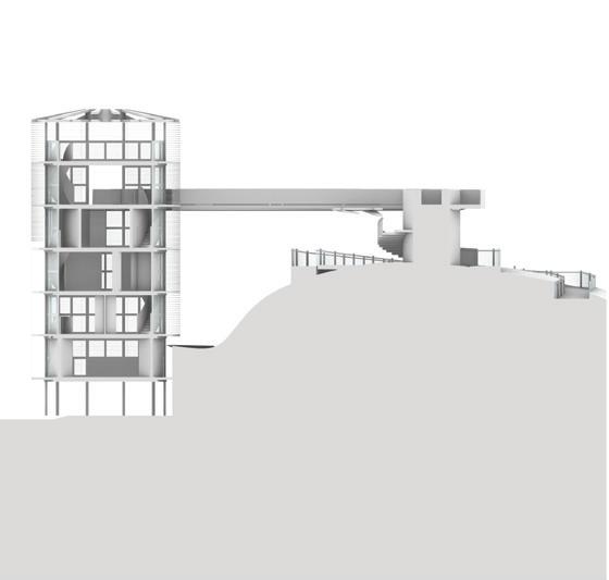
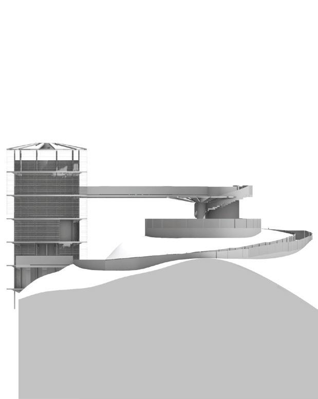
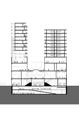
40 SECTION A 1. CAFETERIA 2. GALLERY 3. LOBBY 4. MULTIPURPOSE ROOM 5. AUDITORIUM 6. LIBRARY 7. MEETING ROOM 8. STUDIO 9. FISH BOWL 10. SEMINAR ROOM 11. CLASSROOM 12. THESIS PIT 13. LOG GALLERY 14. MAIN ROOM 15. 2 STORY ROOM 40 SECTION A 1. CAFETERIA 2. GALLERY 3. LOBBY 4. MULTIPURPOSE ROOM 5. AUDITORIUM 6. LIBRARY 7. MEETING ROOM 8. STUDIO 9. FISH BOWL 10. SEMINAR ROOM 11. CLASSROOM 12. THESIS PIT 13. LOG GALLERY 14. MAIN ROOM 15. 2 STORY ROOM 0832
SECTION B 1. CONSTRUCTION LAB 2. LOBBY 3. CAFE 4. GALLERY 5. OFFICES 6. AUDITORIUM 7. MEETING ROOM 8. STUDIO 9. FISH BOWL 10. SEMINAR ROOM 11. CLASSROOM 12. THESIS PIT 13. MAIN ROOM 0832 41 SECTION B 1. CONSTRUCTION LAB 2. LOBBY 3. CAFE 4. GALLERY 5. OFFICES 6. AUDITORIUM 7. MEETING ROOM 8. STUDIO 9. FISH BOWL 10. SEMINAR ROOM 11. CLASSROOM 12. THESIS PIT 13. MAIN ROOM 0832
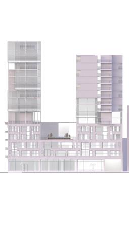
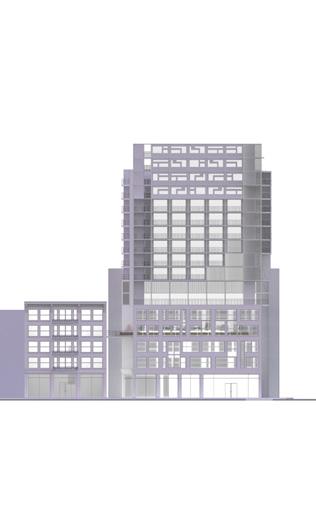
10 42 NORTH FACADE 44 WEST FACADE 43 SECOND YEAR ARC 2021L | SPRING 2020 SOUTH FACADE 45 SECOND YEAR ARC 2021L | SPRING 2020 EAST FACADE
11 SECOND YEAR | ARCHITECTURE SCHOOL TOWER PROJECT 0 8 32
THIRD YEAR SCIENTIST RETREAT PROJECT
12

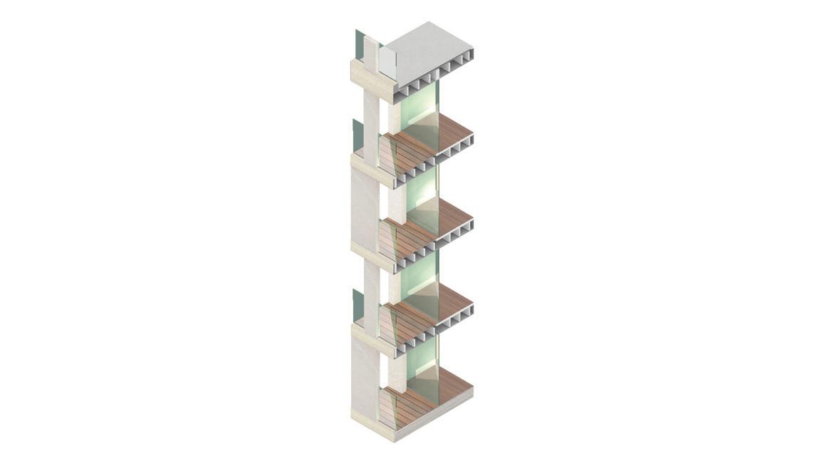
14 LEVEL 1 0’-0” LEVEL 2 0’-0” LEVEL 3 0’-0” LEVEL 4 0’-0” LEVEL 5 0’-0” LEVEL 6 0’-0” ROOF 0’-0” 3/4” PLYWOOD SHEATHING GYPSUM BOARD BATT INSULATION HAT CHANNEL JOISTS @ 24” OC BATT INSULATION WATER BARRIER METAL SIDING METAL STUD STEEL BASE PLATE 1” AIR SPACE SCREWS EXPANSION FLOOR BASE RUBBER WOOD TILES STEEL STRUCTURE METAL DECKING PEDESTAL RIGID INSULATION CPP ARCHITECTURE EMANUEL SERNA TELLEZ DETAILED WALL SECTION FIFTH FLOOR SCALE 1/4” = 1’0” FOURTH FLOOR SCALE 1/4” = 1’0” SIXTH FLOOR SCALE 1/4” = 1’0” SECOND FLOOR SCALE 1/4” = 1’0” FIRST FLOOR SCALE 1/4” = 1’0” 1. TRASH 2. STORAGE 3. KITCHEN THIRD FLOOR SCALE 1/4” = 1’0” 1. DAYROOM 1. BEDROOM 2. CLOSET 3. BATHROOM 1. BEDROOM 2. CLOSET 3. BATHROOM 1. OFFICE 1. LOOKOUT 1 1 1 1 1 1 2 2 3 2 3 2 Section Detail Plans
16 SECTION SCALE 1/4” = 1’0” 1. KITCHEN 2. DAYROOM 3. BEDROOMS 5. ROOFTOP DECK 4. OFFICE 6. MEETING SPACE 7. BATHROOM 1 2 3 CPP ARCHITECTURE EMANUEL SERNA TELLEZ CONNECTION PATHWAY TO PUBLIC AREA PARKING/ WALKWAY TO PRIVATE PREMISE SITE SECTION SCALE 1/8” = 1’0” SITE PLAN/ CIRCULATION SCALE 1/8” = 1’0” Sextions Elevation

17 THIRD YEAR | SCIENTIST RETREAT PROJECT
CPP ARCHITECTURE EMANUEL
CPP ARCHITECTURE EMANUEL SERNA TELLEZ
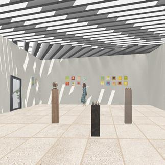
CPP ARCHITECTURE EMANUEL SERNA TELLEZ RENDERINGS
CPP ARCHITECTURE EMANUEL SERNA Views
RENDERINGS / PRESENTATION
RENDERINGS / PRESENTATION
RENDERINGS / PRESENTATION
/ PRESENTATION
THIRD YEAR MIXED-USED PROJECT
18
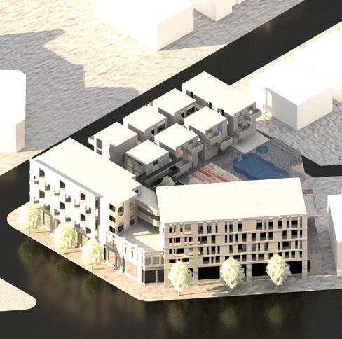
Mixed-Used Project
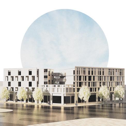
For this project I decided to mainly have a focus on the young professionals demographic, which is apparant in the commercial and congregational areas, as well as with the unit mix types.
The private parking is below grade and commercial parking is at ground level with the commercial area. The commercial area is aimed for younger professionals and includes a gym, a cafe and a convenience store.
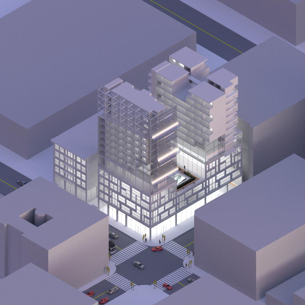
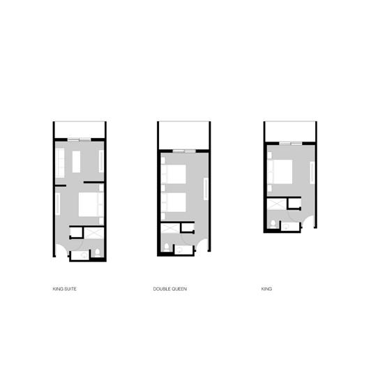
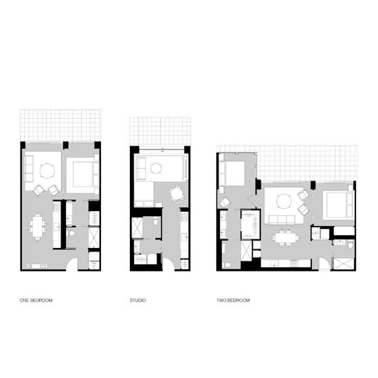
When it comes to massing I treated the program of studio spaces, one bedroom apartments, and two bedroom apartments or townhomes as three seperate entities. This can be seen in the treatment of the program organization, where the studio spaces reflect the residential areas along Prospectand the organization and massing of the one bedroom and townhomes show aspects of their respective streets. Because I wanted to treat these differently, I gave each side a different design element to its facade. For instance, the studios have a village/city like, checkered layout, the townhomes have a more asymmetrical unified design, and the one bedroom apartments are a mixture of both.
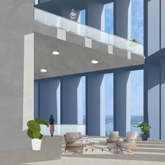
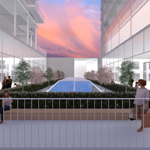
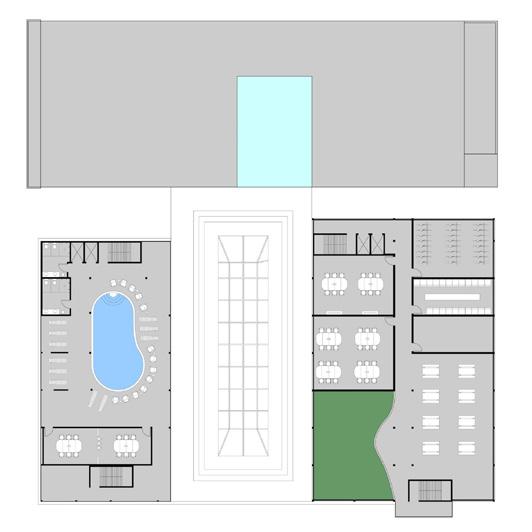
For the congregational areas, there is a shared courtyard for the different units in the center which serves as a getaway with its pool and spa, as well as with a garden. At the third level, both single apartments and townhomes share a balcony deck.
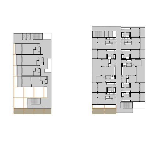
19 THIRD YEAR | MIXED-USED PROJECT PROPOSED PROJECT SCALE: 1’ = 1 / 16” FIRST FLOOR SCALE: 1’ = 1 16” SECOND FLOOR SCALE: 1’ = 1 16” THIRD FLOOR SCALE: 1’ = 1 / 16” FOURTH FLOOR SCALE: 1’ = 1 16” FIFTH FLOOR SCALE: 1’ = 1 16” MASSING STUDY DIAGRAM NTS
Project layout organization
Massing Diagram

20 PROSPECT VERMONT HOLLYWOOD
Site Plan
15' ALLEY
21 THIRD YEAR | MIXED-USED PROJECT 11'-9" 3'-4" 11'-6" 8'-5" 8' 5' 6'-2" 8'-10" 23'-5" 21'-8" 12'-6" 22'-9" 42'-9" 5'-7" 8' 4'-11" 5' 4'-11" 5' 8' 12'-4" 9'-10" 3'-5" 21' 12'-6" 46'-8" 5'-9" 16'-1" 4'-9" 2'-0" 36'-6" 5'-11" 5'-4" 14'-8" 3'-0" 6'-0" 4" 22'-4" 21'-4" 13'-1" 4'-4" 22'-8" 4'-10" 5'-3" 4'-0" 3'-9" 12'-10" 11'-9" 13'-11" 14'-0" 21'-4" 7'-0" 7'-0" 2'-3" 15'-5" 46'-8" 12'-10" 12'-10" 8'-2" 12'-0" 4'-4" 16'-1" 21'-4" 11'-9" 3'-4" 11'-6" 8'-5" 8' 5' 6'-2" 8'-10" 23'-5" 21'-8" 12'-6" 22'-9" 42'-9" 5'-7" 8' 4'-11" 5' 4'-11" 5' 8' 12'-4" 9'-10" 3'-5" 21' 12'-6" 46'-8" 5'-9" 16'-1" 4'-9" 2'-0" 36'-6" 5'-11" 5'-4" 14'-8" 3'-0" 6'-0" 4" 22'-4" 21'-4" 13'-1" 4'-4" 22'-8" 4'-10" 5'-3" 4'-0" 3'-9" 12'-10" 11'-9" 13'-11" 14'-0" 21'-4" 7'-0" 7'-0" 2'-3" 15'-5" 46'-8" 12'-10" 12'-10" 8'-2" 12'-0" 4'-4" 16'-1" 21'-4"
Figure A: Townhome Layout, Second Floor
Figure B: Townhome Layout, First Floor
Figure C: Typica 1 Bedroom Apartment Layout
Figure D: Typical Studio Layout
Figure A
Figure C
Figure B
Figure D
22 ADA STORAGE STORAGE ADA BIKE STORAGE BIKE STORAGE CONVENIECE STORE CAFE GYM LOBBY TRASH STORAGE
Figure 3i: Below Grade Plan
First Floor Plan
23 THIRD YEAR | MIXED-USED PROJECT Fifth Floor Plan Fourth Floor Plan Third Floor Plan Second Floor Plan
Mechanical Legend and Floor Finishes
24 SMOKE AND CARBON MANOXIDE DETECORS BATHROOM EXHAUST WOODEN FLOOR TILE FLOOR S&C E 46'-8" 5'-9" 16'-1" 4'-9" 2'-0" 36'-6" 5'-11" 5'-4" 14'-8" 3'-0" 6'-0" 4" 22'-4" 21'-4" 13'-1" 4'-4" 22'-8" 4'-10" 5'-3" 7'-9" 12'-10" 11'-9" 13'-11" 14'-0" 21'-4" 7'-0" 7'-0" 2'-3" 15'-5" 46'-8" 12'-10" 12'-10" 8'-2" 12'-0" 4'-4" 16'-1" 21'-4"
25 THIRD YEAR | MIXED-USED PROJECT + 60’ - 0” ROOF + 48’ - 0” 5TH FLOOR + 38’ - 0” 4TH FLOOR + 28’ - 0” 3RD FLOOR + 18’ - 0” 2ND FLOOR + 0’ - 0” GROUND FLOOR
Section Perspective
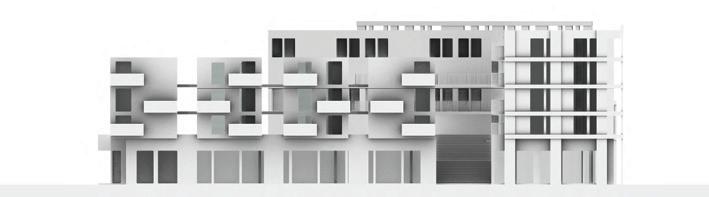
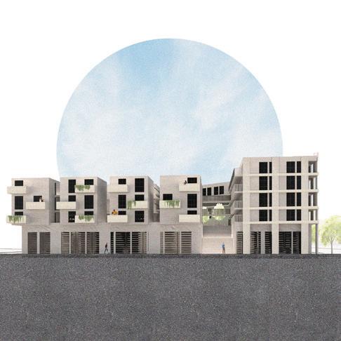
Elevation from Hollywood
ELEVATION FROM HOLLYWOOD SCALE: 1/8” = 1’
Elevation from Prospect
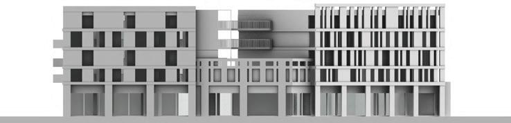
ELEVATION FROM PROSPECT SCALE: 1/8” = 1’
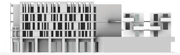
Elevation from Vermont
ELEVATION FROM VERMONT SCALE: 1/8” = 1’
26
27 THIRD YEAR | MIXED-USED PROJECT CIRCULATION DIAGRAM VERTICAL CIRCULATION HORIZONTAL CIRCULATION
Project Axon Circulation Diagram

28 Dual zone condenser Dryer exhaust Dryer Mini Split Hood roof vent Kitchen hood MECHANICAL DIAGRAM SCALE: 1’ = 1 / 8” HVAC SYTEM EXHAUST SYSTEM BATHROOM EXHAUST Mechanical Diagram PLUMBING DIAGRAM SCALE: 1’ = 1 8” GRAY WATER BLACK WATER ROOF DRAIN COLD WATER HOT WATER MAIN LINE Cistern Gray water tank Irrigation Cistern SewerLine MainLine StormDrain Roof drain Water heater Vent stack
28
Plumbing Diagram
29 THIRD YEAR | MIXED-USED PROJECT J bead (2) layers of building paper 5/8” glass sheathing 1” gypcrete Plywood Insulation 2x12 girder Concrete slab Concrete floor drain 1/2” acousticork Hardwood floor finish Mullion Frameless glass railing Awning window Floor drain Wood Decking Metal coping Top plates 3/4” plywood Building paper Water proofing membrane Mortar Ceramic tile cant strip Section Detail Elevation
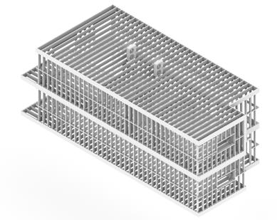
30 STRUCTURAL DIAGRAM NTS
Structural Diagram
J bead Stucco (2) layers of building 5/8” glass sheathing 1” gypcrete Plywood Insulation 2x12 girder Concrete slab Concrete floor drain 1/2” acousticork Hardwood floor Mullion Frameless glass railing Awning window Floor drain Wood Decking Metal coping Top plates 3/4” plywood Building paper Water proofing Mortar Ceramic tile Stucco cant strip
Structural Diagram
31 THIRD YEAR | MIXED-USED PROJECT
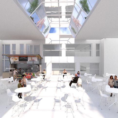
Perspective Rendering from Prospect
Perspective Rendering from Hollywood and Vermont
FOURTH YEAR LIVING WALL
32
33 FOURTH YEAR | LIVING WALL
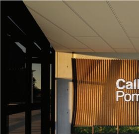
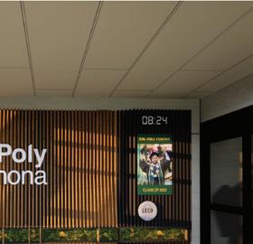
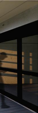
1. FRONT VIEW
Front View
34 5'-5" 2'-11" 9" 9" 17'-5" 8" 9" 16'-0" 18'-2" 9" 17'-5" 8" 9" 16'-0" 18'-2" 9" EXISTING SECURITY CAMERA EXISTING ACOUSTIC PANEL DROP CEILING CLEAR WIDTH DOORS TO FRONT FACE OF WALL CLEAR WIDTH DOORS TO FRONT FACE OF WALL EXISTING AIR CONDITIONING VENT EXISTING SPRINKLERS FIRE CONTROL PANEL LOCATION EXISTING DOWN LIGHTS ENTRY VESTIBULE 9’ CLG METAL GRATE FLOOR ENTRY VESTIBULE FLOOR PLAN SCALE 1/2” = 1’-0” ENTRY VESTIBULE REFLECTED CEILING PLAN SCALE 1/2” = 1’-0” R R R R SD FA 3. FLOOR PLANS 2" 1'-0" 1'-7" 2" 9" 3'-9" 4'-7" 3'-11" 1'-0" 17'-8" 16'-0" 1'-0" 18'-8" 8" 9'-0" 9" 7'-10" 1" 4" 1'-10" 2'-2" 2'-2" 10" 11" 9'-0" 7'-10" 1" 4" 11" 10" 1'-1" 4" 3" 3'-2"6"6" 4" 9" LIVING WALL BOTTOM ELEVATION SCALE 1/2” = 1’-0” LIVING WALL TOP ELEVATION SCALE 1/2” = 1’-0” LIVING WALL BACK ELEVATION SCALE 1/2” = 1’-0” LIVING WALL FRONT ELEVATION SCALE 1/2” = 1’-0” LIVING WALL LEFT ELEVATION SCALE 1/2” = 1’-0” LIVING WALL RIGHT ELEVATION SCALE 1/2” = 1’-0” DIGITAL CLOCK TV LEED MOSS ATTACHMENT PATTERN 12” O.C (OFFSET EVERY OTHER RIB) A.5 6 4. ELEVATIONS Floor Plans Elevations
35 FOURTH YEAR | LIVING WALL SCALE: 1-1/2" = 1'-0" STANDARD MOSS BOX SECTION SCALE: 1-1/2" = 1'-0" STANDARD FULL LENGTH RIB SECTION SCALE: 1-1/2" = 1'-0" STANDARD DIGITAL WALL RIB SECTION 5 A.5 1 A.5 2 A.5 3 A.5 4 A.5 3/4” FIRESHIELD PLYWOOD APPLIED WITH ONE COAT OF WATER BASED STAIN FRONTSIGNS CPP STACKED WORDMARK GROWUP PRESERVED MOSS TAPERED BOTTOM EDGES OF RIBS EXISTING 4” METAL KICK PLATE ORANGE ALUMINUM MUSTANG Z-RAIL SYSTEM NOTCHES CUT FROM RIBS TO ATTACH SIGN FASTEDGE EDGEBANDING #9 WOOD SCREWS SECURING RIBS 1/4” RUBBER SPACER DIGITAL CLOCK ANNOUNCEMENT SCREEN LEED AWARD LED LIGHTS IN ENCLOSURE 3/4” PLYWOOD FRAMING FOR MOSS SPECIFIC ANGLES AND DIMENSIONS WILL VARY PER RIB FOR ACCURATE ASSESSMENT OF RIB DESIGNS, CNC FABRICATOR IS PROVIDED WITH A DIGITAL CUT-OUT TEMPLATE FOR ALL 96 RIBS 5" 3" 5" 4" 9" SCALE: 1-1/2" = 1'-0" STANDARD RIB PLAN SCALE: 1-1/2" = 1'-0" STANDARD SIGN PLAN SCALE: 1-1/2" = 1'-0" STANDARD DIGITAL PLAN 1'-0” 4" 5" 10" 7'-10" 11" 1'-1" 8" 3" 6" 6" 11" 10" 1'-5" 11" 1'-6" 9" 3" 9" 7'-10" 10" 9" 8" 3" 6" 4" 1'-0” 9" 4" 5" 7'-10" 4" 3'-2" 4" 5. SECTIONS Sections NEW 110V PLUG, INSTALLED BY OTHERS SECURE ALL WIRING RUNNING TO 110V PLUG LED STRIP, TELEVISION, AND DIGITAL CLOCK WIRING SCALE: 4" = 1'-0" SCHEMATIC ELECTRICAL ONE-LINE WIRING DIAGRAM SCALE: 4" = 1'-0" TYP. RIB DETAIL ALUMINUM LED CHANNEL PHILIPS LIGHTSTRIP OUTDOOR LEDS TYP. MOSS BOX DETAIL SCALE: 4" = 1'-0" MUSTANG Z-CLIP, ATTACHED THROUGH 2 RIBS MUSTANG Z-RAIL, ATTACHED TO CONCRETE TYP. Z-RAIL DETAIL SCALE: 4" = 1'-0" SCALE: 4" = 1'-0" TYP. SPACER DETAIL 1 2 3 4 5 3/4" FIRESHIELD PLYWOOD APPLIED WITH ONE COAT OF WATER BASED STAIN GROWUP PRESERVED MOSS, INSTALLED BY VENDOR 3/4” FIRESHIELD PLYWOOD APPLIED WITH ONE COAT OF WATER BASED STAIN #9 WOOD SCREW, PREDRILLED AND SET FLUSH 1/4" RUBBER STAND-OFF SPACER W/ ADHESIVE BACKING 1/4” TAPCON CONCRETE ANCHOR HOLE PRE-DRILLED TO 2-1/2” ANCHOR EMBEDMENT DEPTH W/ 1/2” EXCESS, SECURING SPACER, 24” O.C. FASTEDGE EDGEBANDING ON OPEN EDGE EXISTING 4” METAL KICK PLATE ORANGE ALUMINUM MUSTANG Z-RAIL SYSTEM 3" x 3/8" TAPCON CONCRETE ANCHOR, 2-1/2" MIN. EMBEDMENT, INSTALLED PER MANUFACTURER REQS. TYP. WALL ELEVATION DETAIL SCALE: 4" = 1'-0" 6 TYP. SPACING BETWEEN RIBS @ 2-1/4” O.C CORNERS FILLETED @ 3/8” FOR EDGEBANDING 2-1/4" 1/4" 3-1/4" 1/2" 1” 4-1/2” 2-1/2” 3/4" 1/2" Details
36 3/4” FIRESHIELD PLYWOOD BACKING 3/4” FIRESHIELD PLYWOOD RIBS FASTEDGE EDGEBANDING 3/4” FIRESHIELD MOSS BOX FRAMING GROWUP PRESERVED MOSS #9 WOOD CABINET SCREWS Z-RAIL CLIPS, ATTACHED THROUGH 2 RIBS Z-CLIP PLACED OVER AND INTO Z-RAIL GROOVE Z-RAIL ATTACHED TO CONCRETE W/ CONCRETE ANCHORS NEW 110V PLUG POWER STRIP DIGITAL WALL CLOCK ANNOUNCEMENT SCREEN LEED AWARD FRONTSIGNS CPP STACKED WORDSTAMP LOGO STEP 1 STEP 2 STEP 3 STEP 4 The wall consists of 8 separate modules consisting primarily of 3/4” Fireshield Plywood Ribs and Backing. The Ribs will be CNC’d by an outside vendor and once completed will be pre-drilled every 12” with a 6” offset on alternating ribs for mounting ribs to the backing. The plywood will be coated with a stain, edge-banding will be applied to the open faces of the plywood, and an application of intumescent paint to ensure fire safety. The pre-drilled holes will now be used to attach the ribs to the backing from the rear. The screw pattern is offset on alternating ribs to maintain structural integrity of the plywood. Every module will be attached with a pair of Mustang Z-Rail Clips, spaced so as to connect to 2 ribs and distribute load more evenly. On site, a Mustang Z-Rail spanning the length of the Living Wall will be installed into the concrete wall with 3/8” Tapcon Concrete Anchors. Each module will be lifted 1” over the rail, set into the groove, and then pressed flush against the previous module. Once all modules are installed and secured with rubber standoffs, the electronics and LEED Award can be installed. Installation of the logo will be handled by vendor. LED lights will be fed through the aluminum channels cut out for them, and the wiring will be passed up along the back of the wall along with wiring for the screen, wall clock, and signage. Wiring will be secured along the top of the wall and connected to a power strip, which will connect to a new 110V plug. Assembly Diagram
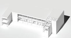
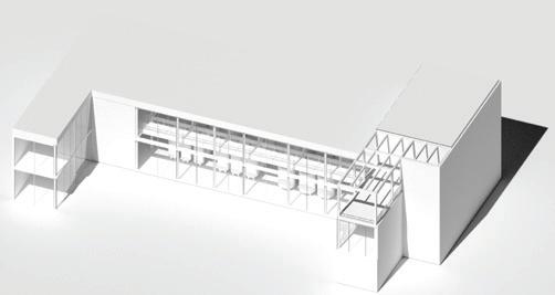
FIFTH YEAR PRESERVATION PROJECT
37 FIFTH YEAR | PRESERVATION PROJECT
38
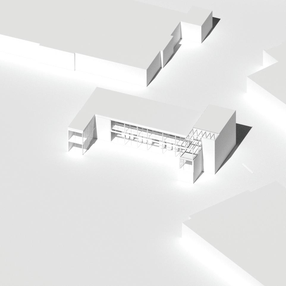
Preservation Project Axon


39 FIFTH YEAR | PRESERVATION PROJECT 3RD STREET
3RD STREET BROADWAY APARTMENT LOBBY HOTEL LOBBY KITCHEN Site Plan Ground Floor Plan
BROADWAY
40 Second Floor Retail
41 FIFTH YEAR | PRESERVATION PROJECT KITCHEN GROCERY STORE DAYCARE BAR Third Floor Plan
Third Floor Plan Third Floor Plan
43 FIFTH YEAR | PRESERVATION PROJECT Third Floor Plan Third Floor Plan
44
Setion from 3rd Street
Elevation from Third Street
Section from Broadway
Elevation from Broadway
45 FIFTH YEAR | PRESERVATION PROJECT
FIFTH YEAR URBAN WINERY
46
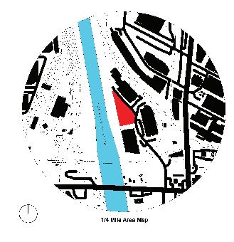
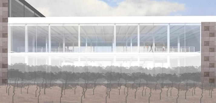
A proposed urban winery in the industrial area of Boyle Heights, Los Angeles, would provide a unique and innovative use for the neighborhood’s underutilized industrial area. It would offer a unique and exciting opportunity to bring together the neighborhood’s vibrant culture and rich history with the growing interest in urban winemaking. The winery would be set adjacent to the LA River and would surely attract residents and visitors alike. Although it is set in close proximity to industrial buildings, the winery will attract visitors with the implementation of courtyards and outdoor and indoor spaces. The grapes used to make the wine would be grown in nearby vineyards and carefully selected to ensure the highest quality. The winemaking techniques used would be traditional and sustainable, producing a range of delicious and distinctive wines. In addition to providing economic benefits, such as job creation and tax revenue, the urban winery would also contribute to the neighborhood’s sense of community and identity. Despite potential challenges, a proposed urban winery in Boyle Heights has the potential to be a successful and valuable addition to the neighborhood.
47 FIFTH YEAR | URBAN WINERY
1/4
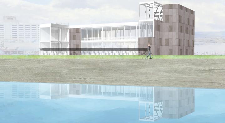
View from LA River
Mile Radius
48 Zoning Analysis Legal Infor mation: Site Address: 1611 S PERRINO PL Site Address: 1607 S PERRINO PL ZIP Code: 90023 PIN Number: 118-5A219 11 Lot/Parce Area (Calculated): 40,000 (sq ft) Site Info: Assessor Parcel No (APN): 5169015010 Tract: TR 8626 Map Reference: M B 121-96/100 Block: None Lot: FR LT 3 FAR: 1 5:1 Height Limit: NA Jur isdiction: Community Plan Area: Boyle Heights Area Plann ng Commission: East Los Angeles Neighborhood Council: Boyle Heights Council D strict: CD 14 - Kevin de León Census Tract #: 2060.50
49 FIFTH YEAR | URBAN WINERY Steel Momemt Framing Shear walls STRUCTURAL DIAGRAM SUN STUDIES DIAGRAM View from East, June 3pm Standard Glazing Channel/Frosted Glazing PROGRAMMATIC DIAGRAM Storage Employee Facilities Production Catwalk Back of House Kitchen Restaurant Lobby Bathroom Store
Programmatic Diagram
Sun
Structural Diagram
Studies/Environmental Diagram
50 A A B B 4 3 5 6 7 8 5 A A B B C C E E D D 1 2 2 SECOND FLOOR PLAN 1/32” 1. Restaurant 2. Lobby 3. Restrooms 4. Production Catwalk/ Tour A. Crushing B. Fermentation C. Filtration D. Aging E. Bottling 5. Employee Restrooms 6. Breakroom 7. Meeting Room 8. Of ice Public Parking Entrance PERRINO PL Loading Lot Courtyard Property Line L OS A NGELE S RIV ER LOS ANGELE S RIV ER TRAIL 1 2 3 4 A A B B 5 6 7 8 9 10 GROUND FLOOR PLAN 1/32” 1.Lobby 2.Kitchen 3.Back of House 4.Courtyard 5.Crushing 6.Fermentation 7.Filtration 8.Aging 9.Bottling 10.Storage/Loading
51 FIFTH YEAR | URBAN WINERY Section B 1 2 3 1/16“ 1. Parking 2. Fermentation 3. Courtyard Section A 1/16“ ” 1. Parking 2. Storage/Loading 3. Bottling 4. Aging 5. Fermentation 6. Filtration 7. Crushing 8. Lobby 9. Store 1 2 3 4 5 6 7 8 8 9 4
52
View from Catwalks
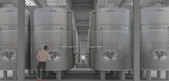
View from Production
View from the Street
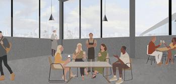
Restaurant View
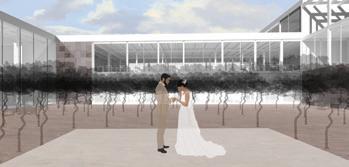
View from Courtyards