Product Summary_bros_en

Page 1

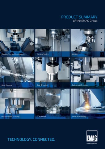
PRODUCT SUMMARY of the EMAG Group

www.emag.com
Turning Chucked Components Turning Shafts Milling Gear Hobbing Gear Grinding Cylindrical Grinding Out-of-round Grinding ECM/PECM Laser Processing
TECHNOLOGY. CONNECTED.
CONTENTS » EDNA IoT PRODUCTS EDNA IoT products at a glance 4 EDNA Health Check 6 EDNA Visualize 6 EDNA Edge Cloud .................................... 6 EDNA IoT Ready 7 EDNA Services 7 » TURNING BUSINESS UNIT EMAG VL 2/VL 4/VL 6/VL 8 8 EMAG VL 3 DUO 9 EMAG VLC 100/VLC 200/VLC 300/VLC 400 10 EMAG VT 2/VT 4 ...................................... 12 EMAG VTC 100/VTC 200 12 EMAG VTC 250/VTC 250 DUO 13 EMAG VSC 250/400/500 14 EMAG VSC 250/400/450/500 DUO 14 EMAG VSC 160 TWIN 15 EMAG VSC 315 TWIN KBG 16 EMAG VSC 315 KBU/VSC 315 DUO KBU 16 EMAG HCM 110 17 EMAG VM 9 18 EMAG VSC 400 PS 19
GRINDING BUSINESS UNIT EMAG REINECKER VSC 250 DS/ VSC 400 DS/DDS 20 EMAG REINECKER VSC 250 DUO DS/ VSC 400 DUO DS ..................................... 20 EMAG VLC 200 GT/VLC 350 GT 22 EMAG VTC 100 GT 24 EMAG VTC 315 DS 24 EMAG KOPP VG 110 25 EMAG WEISS W 11 CNC ............................. 26 EMAG WEISS W 11 26 EMAG WEISS W 27/W 37/W 50 27 EMAG WEISS WPG 7 28 EMAG WEISS WUG 21 28 EMAG WEISS ECO 200/GCU 350/GCH 440 ...... 29 EMAG KARSTENS HG 2/HG 204/HG 208 30 EMAG KARSTENS HG 208 CD 30 EMAG KARSTENS HG 208 DW 31 EMAG KOPP SN 204/208 32 EMAG KOPP SN 310/320 32 » SOFT GEAR CUTTING BUSINESS UNIT EMAG KOEPFER K 160 34 EMAG KOEPFER K 300 34 EMAG KOEPFER HLC 150 H 35 2
TABLE OF
»
UNIT EMAG SU CLC 200/300/500/600 W/900 W 36 EMAG SU CLC 260 H/500 H 36 EMAG SU CLC-SZ Series. 37 EMAG SU RASO 200/400 ............................ 38 EMAG SU GS 400 38 EMAG SU G 375/G 500 H/HL/GP 500 H/HL/ GW 3600 H/TC 39 EMAG SU G 160/G 250/G 400/G 250 HS 40 EMAG SU SG 160 SKYGRIND ....................... 40 EMAG SU CLC 260 H-FR/CLC 500 H-FR 41 EMAG SU G 375 H/GR 500 HL/GRX 500 H/ GW 3600 HD 41 EMAG SU CLC 200 FR 42 EMAG SU GW 250/GR 250 .......................... 42 EMAG SU HRG 350 43 EMAG SU CLC 350 CH/SCT 3 43 » LASERTEC BUSINESS UNIT EMAG ELC 160 44 EMAG ELC 160 HP 44 EMAG ELC 250 DUO 45 EMAG ELC 6 46 EMAG ELC 600 46 EMAG ELC 1200 V 47 EMAG ELC 1200 H 47 EMAG ELC LC 4 48 EMAG ELC 1300 LH 48 EMAG SFC 600 ....................................... 49 »
EMAG Comfort Integrated (CI) 50 EMAG Comfort Standard (CS) 50 EMAG Premium Integrated (PI) 51 EMAG Premium Integrated (PS)...................... 51 EMAG PECM PTS System 52 EMAG PECM PO 100 SF System 54 EMAG PECM PO 900 BF System 51 EMAG Elektrolyt-Management-System (EMS) 55 » AUTOMATION BUSINESS UNIT EMAG TrackMotion 4/8 56 EMAG SCS 1/4 ......................................... 57 EMAG Bin Picking Zelle 57 TABLE OF CONTENTS 3
» HARD GEAR CUTTING BUSINESS
ECM BUSINESS UNIT

EMAG IOT PRODUCTS

Health Check

asset_selector : { "customer": 1, "place": 1, "building": 1, line : "3", "operation": "*" "machine": "*" }

Data Science

Services Visualize
Edge Cloud
IoT Ready
4

YOUR ADDED VALUE PRODUCTS IN OVERVIEW:

Health Check

Edge Cloud

Visualize

IoT Ready

Visualize

EDNA Lifeline Dashboard EDNA Edge Cloud Server Machine Status App Cycle Time App Workpiece Counter App OEE App Smart-Tool-Change App EDNA Cloud
Advanced
EDNA IOT PRODUCTS EDNA Core Industrial PC EDNA Sense Additional Sensors EDNA Cortex Software License EDNA Health Check Lite Health status on demand EDNA Cortex Software License Data Science Pipeline Data Science Toolkit EDNA Health Check Predictive Maintenance 5

EMAG IoT PRODUCTS

1 Health Check

Higher availability through predictive maintenance and lower service costs

» Predictive maintenance: early detection of negative trends and condition of machine components

» Reduction of unplanned downtimes

2 Visualize

Live transparency of the current production output

» Planning reliability and reduction of downtimes

» Modern collection and clear presentation of relevant data

3

Edge Cloud

Central edge storage and collection of all machines and data

» Data is stored in a central location in the customer network

» Comparison of several machines or lines possible

» The data does not leave the customer‘s plant

Machine Status Visualize Standard Apps Visualize Advanced Cycle time Workpiece counter OEE Smart-Tool-Change + Customer
EDNA Cortex Software License Data Science Pipeline Data Science Toolkit Included EDNA Products 6
Health Line Chart (Example of VSC 250 DUO) Network EDNA EDGE Cloud Server

4 IoT Ready

Future-proofing, compatibility and machine data

» PDA/MDA interface

» Control-independent and safe hardware

» Health Check Lite included

» Various interfaces for connection to EMAG or third-party systems

5 Services Industry 4.0 basic workshop for EMAG customers

» We show concrete optimization potentials through Industry 4.0 and corresponding solutions

Initial discussion

Current challenges & optimization potentials in your production

Workshop Industry 4.0

Potentials of your production & selection of suitable solution options

1 workshop day + follow-up Cost: 1.900 €

» Recommendations for Industry 4.0 potentials in your production

» Quantify potential for savings or performance improvement

SUCCESS STORY

Kunde MAT ist begeistert von den IoT-Lösungen von EMAG

MAT Machining Europe GmbH has decided to gradually equip its production lines with EMAG‘s IoT solution. MAT is an automotive supplier and manufactures complex differential gear housings on several fully automated EMAG production lines.

OEE increase

11%

EDNA IOT PRODUCTS
IPC: EDNA Core
MAT - Video
Vibration Sensor EDNA Sense
1 2 3
7

EMAG VL 2 · VL 4 · VL 6 · VL 8

BENEFITS OF THE VL SERIES

» The machines of the VL Series are space-saving vertical turning machines with integrated automation. They deliver maximum performance and low costs per piece. This performance is based on high-quality components. The machine body is made of MINERALIT® polymer concrete with damping properties.

» A pick-up working spindle moves in the X- and Z-axes with minimum response times and the tool turret guarantees short swiveling times.

» Furthermore, the machines can be fitted with a Y-axis in the turret to allow for the machining of complex geometries. The possible fields of applications for the machines are thus increased massively.

VL 2 VL 6 TECHNICAL DATA VL 2 VL 4 VL 6 VL 8 Max. chuck diameter mm in 160 6.5 260 10 400 15.5 500 19.5 Swing diameter mm in 210 8.5 280 11 420 16.5 520 20.5 Max. workpiece diameter mm in 100 4 200 8 300 12 400 15.5 Max. workpiece length mm in 150 6 200 8 250 10 300 12 X-axis travel mm in 640 25 740 29 885 35 1,110 44 Y-axis travel mm in ±50 ±2 ±30 ±1 ±30 ±1 ±30 ±1 Z-axis travel mm in 375 15 415 16.5 495 19.5 595 23.5 Power rating (40%/100% duty cycle) kW hp 18.1/13.9 24/19 25/18 34/24 39/28 52/38 47.6/34.6 64/46 Torque (40%/100% duty cycle) Nm ft-lb 77/59 57/44 280/202 207/149 460/340 339/251 780/600 575/443 Speed rpm 6,000 4,500 3,100 2,850 VL 8
VL 4 8

EMAG has extended the product range of the extremely successful VL Series in the form of the VL 3 DUO, a twin-spindle machine solution for the highly productive manufacturing of chucked parts with a diameter of up to 150 mm.

The VL 3 DUO integrates all of the most recent EMAG technological developments (including self-loading spindle, the TrackMotion automation system and the modular design of the machine) to create a highly productive manufacturing system with a minimum footprint.

DUO TURNING BUSINESS UNIT
TECHNICAL DATA VL 3 DUO Max. workpiece diameter mm in 150 6 Chuck diameter mm in 210 8 Max. workpiece length mm in 110 4.5 X-axis travel (machining) mm in 505 19.5 Y-axis travel (optional) mm in ±30 ±1 Z-axis travel mm in 250 10 Power rating (40%/100% duty cycle) kW hp 17.9/15.5 24/21 Torque (40%/100% duty cycle) Nm ft-lb 144/98 106/72 Speed rpm 5,000
EMAG VL 3
VL 3 DUO
9

EMAG VLC 100 · VLC 200 · VLC 300 · VLC 400

BENEFITS OF THE VLC SERIES

» Individual manufacturing solution: The VLC Series machines can be adjusted individually to the machining requirement.

» Turning tools, milling spindles, and multi-spindle drill head modules are available.

VLC 100 VLC 200 VLC 300 TECHNICAL DATA VLC 100 VLC 200 VLC 300 VLC 400 Max. chuck diameter mm in 160 6.5 260 10 400 15.5 500 19.5 Swing diameter mm in 210 8.5 280 11 420 16.5 520 20.5 Max. workpiece diameter mm in 100 4 200 8 300 12 400 15.5 Max. workpiece length mm in 150 6 200 8 250 10 300 12 X-axis travel mm in 650 26 760 30 900 35 1,010 40 Y-axis travel mm in ±50 ±2 ±30 ±1 ±30 ±1 ±30 ±1 Z-axis travel mm in 375 15 415 16 495 19 595 23 VLC 400
10
TURNING BUSINESS UNIT 11

VT 2/VT 4

VTC 100/VTC 200

Four axes, short distances, and a powerful main spindle – these are the strengths of the VT Series. Fast processes are required for machining large quantities of shafts. Both the machining process and the loading and unloading processes must be completed extremely quickly. VT 2 and VT 4 machines guarantee the high performance you require.

The benefits of the VT Series come to light in particular where high numbers of parts are involved. A key factor here is the machining of parts from two sides. This greatly reduces the machining time. Two tool turrets, each with eleven tool positions that can be equipped with turning tools or driven tools, ensure machine flexibility.

The strength of the VTC Series machines is their 4-axis machining of large quantities of shafts up to 400 mm in length. Since the machine concept comprises a fully integrated automated loading and unloading system, a manufacturing system can be created, which features very short transport distances. The machines are loaded and unloaded by the two turrets, which ensures that the process is fast and straightforward.

In addition, it has a powerful main spindle. For the machining process, there are two turrets with eleven tool positions, which can be equipped with either turning tools or driven tools. The 12th station is for the gripper which handles the parts in the machine. There are endless transport belts on both sides of the machining area. This is where the raw and finished parts are stored.

TECHNICAL DATA VTC 100 VTC 200 Chuck diameter mm in 160 6.5 250 10 Swing diameter mm in 210 8.5 270 10.5 Max. part diameter » Gripper diameter mm in 63 2.5 133 5 » Workpiece diameter mm in 100 4 200 8 Max. workpiece length mm in 400 15.5 630 25 X-axis travel mm in 332 13 395 15.5 Y-axis travel mm in ±25 ±1 ±25 ±1 Z-axis travel mm in 625 24.5 810 32
TECHNICAL DATA VT 2 VT 4 Chuck diameter mm in 160 6.5 250 10 Swing diameter mm in 210 8.5 270 10.5 Max. part diameter » Gripper diameter mm in 63 2.5 133 5 » Workpiece diameter mm in 100 4 200 8 Max. workpiece length mm in 400 15.5 630 25 X/Z-axis travel mm in 332/625 13/24.5 395/810 15.5/32 Power rating (40%/100% duty cycle) kW hp 21/14.1 28/19 38/29 51/39 Torque (40%/100% duty cycle) Nm ft-lb 130/90 96/66 250/200 184/148 Speed rpm 6,000 4,500
12
EMAG VT 2 · VT 4 · VTC 100 · VTC 200 CUSTOMIZED

EMAG VTC 250/VTC 250 DUO

VTC 250/VTC 250 DUO

Completely machine shafts and shaft-type workpieces on a single machine, including automation.

As a result of their high drive rating and robust components, the machines in the VTC Series are highly productive turning centers. In the form of the VTC 250 DUO DD/ED, the machine can be fitted with two machining stations and three tool turrets. One special feature is the simple, low-cost workpiece transport completed by the turrets.

TURNING BUSINESS UNIT
TECHNICAL DATA VTC 250/VTC 250 DUO Chuck diameter mm in 250 10 Max. workpiece diameter mm in 140 5.5 Max. workpiece length mm in 630/1,000* 25/39.5* X-axis travel mm in 300 12 Z-axis travel mm in 740/1,100* 29/43.5*
length
*Special
13

Vertical pick-up turning machine for chucked parts with a diameter of up to 440 mm. Excellent use of the VSC Series by technology integration for both soft and hard machining.

Turning, drilling, grinding, milling, gear cutting and honing – all in one machine. The workpiece is measured precisely, quickly and without delays in the machining position by a measuring probe or measuring mandrel.

The low-cost solution for machining small and medium workpieces in two operations. The DUO design has two separate machining areas, which means that it has overhead slides that can be programmed independently.

Each machining area has an EMAG disk-type tool turret at the end that can be independently programmed.

DUO
EMAG VSC 250/400/450/500 · VSC 250/400/450/500
VSC 250/400/450/500
VSC 250/400/450/500 DUO
TECHNICAL DATA VSC 250 DUO VSC 400 DUO VSC 450 DUO VSC 500 DUO Workpiece diameter (nominal) mm inch 250 10 340 13.5 400 16 440 17.5 Chuck diameter mm inch 315 12.5 400 16 460 18 500 20 Swing diameter mm inch 330 13 420 16.5 520 21 520 21 X-axis travel mm inch 900 35.5 860 34 935 37 935 37 Z-axis travel mm inch 300 12 315 12.5 315 12.5 400 16 14

EMAG VSC 160 TWIN

VSC 160 TWIN

The ideal machines for high performance, high accuracy, and large series – the vertical multi-spindle machines for the simultaneous machining of two workpieces.

The VSC TWIN Series combines highly productive output with a minimal footprint.

TURNING BUSINESS UNIT TECHNICAL DATA VSC 160 TWIN Workpiece diameter (nominal) mm in 130 5 Chuck diameter mm in 130/160 5/6.5 Swing diameter mm in 180 7 X-axis travel mm in 860 34 Z-axis travel mm in 160 6.5 15

MACHINES FOR MACHINING HOMOKINETIC JOINTS

VSC 315 TWIN KBG

VSC 315 KBU/VSC 315 DUO KBU

KBG Straight ball raceways

KBU Universal ball raceways

TECHNICAL DATA VSC 315 KBU/VSC 315 DUO KBU Chuck diameter mm in 250/250 10/10 Swing diameter mm in 260/260 10/10 X-axis travel mm in 900/900 35.5/35.5 Y-axis travel mm in 315/315 12.5/12.5 Z-axis travel mm in 300/300 12/12 Main drive unit # 1/2 Spindle flange to DIN 55026 Size 8/8 Spindle bearing diameter, front mm in 140/140 5.5/5.5 Max. speed rpm 3,000/3,000 AC synchronous motor, 40%/100% duty cycle kW hp 28.5/27.5/28.5/27.5 1/0.5/1/0.5 Maximum power kW hp 28.5/28.5 1/1 Full performance from spindle speed rpm 700/700 Torque, 40%/100% duty cycle Nm ft-lb 590/375/590/375 23/15/23/14.5 Maximum torque Nm ft-lb 590/590 23/23 TECHNICAL DATA VSC 315 TWIN KBG Chuck diameter mm in 250 10 Swing diameter mm in 260 10 X-axis travel mm in 850 33.5 Z-axis travel mm in 320 12.5 Main spindle # 2 Spindle flange to DIN 55026 Size 8 Spindle bearing diameter, front mm in 140 5.5 Max. speed rpm 3,000 Spindle distance mm in 500 20 Main drive unit # 2 AC asynchronous motor, 60%/100% duty cycle kW hp 58/45 78/60 Maximum power kW hp 58 78 Full performance from spindle speed rpm 900 Torque, 60%/100% duty cycle Nm ft-lb 620/480 457/354 Maximum torque Nm ft-lb 620 457
16
TECHNICAL DATA HCM 110 Max. workpiece diameter mm in 110 4 Min. workpiece diameter mm in 30 1 Max. workpiece height mm in 60 2 Min. workpiece height mm in 15 0.6 Max. workpiece weight kg lbs 1 2 Spindle flange to DIN 55026 Size 5 Machine weight t lbs 8 18,000 HCM 110 TURNING BUSINESS UNIT 17

The vertical turning centers in the VM Series are designed for the highly productive manufacturing of workpiece families with a wide range of parts. A tool turret with twelve tool positions, depending on the required tool interface in a BMT or VDI version, is available for machining. The turret can be equipped with driven tools to carry out drilling operations, for example.

9
TECHNICAL DATA VM 9 Max. chuck diameter mm in 450 17.5 Swing diameter mm in 700 27.5 X-axis travel mm in 375 14.5 Z-axis travel mm in 500 19.5 Y-axis travel mm in ––
VM
EMAG VM 9
18

EMAG VSC 400 PS

VSC 400 PS

Fast, precise, and easy to operate: power skiving has been turned into a highly efficient process for the production of internal and external gear teeth by the VSC 400 PS machine.

TURNING BUSINESS UNIT TECHNICAL DATA VSC 400 PS Max. chuck diameter mm in 400 16 Swing diameter mm in 420 17 Workpiece diameter mm in 340 (400) 13 (16) X-axis travel mm in 935 37 Z-axis travel mm in 315 12 Y-axis travel mm in 280 11
19

EMAG REINECKER VSC 250 DS · VSC 400 DS/DDS

The combined turning and grinding centers combine the benefits of vertical hard turning with those of grinding –on a single machine and in a single clamping operation.

The optimum, most economical machining process is used, depending on the workpiece and the quality requirements. The benefit for the customer is the flexibility of selecting the best technology for each machining process – hard turning, scroll-free turning, and grinding on a single machine.

This machine reduces the process chain and delivers a whole series of benefits for the user: lower investment costs and costs per piece, shorter throughput times and higher workpiece quality with greater process reliability.

The twin-spindle turning and grinding machines of the DUO Series are a very economical solution for the machining of larger batches for small and medium-sized workpieces. The DUO has the smallest footprint of the machines for the machining of components in first and second operation. The machines have two separate machining areas which means that they have overhead slides which can be programmed independently.

VSC
VSC 250 DUO DS/VSC 400 DUO
TECHNICAL DATA VSC 250 DS VSC 400 DS/DDS VSC 250 DUO DS VSC 400 DUO DS Max. chuck diameter mm in 250/315 10/12.5 400 15.5 250/315 10/12.5 400 15.5 Max. swing diameter mm in 330 13 420 16.5 330 13 420 16.5 X-axis travel mm in 900 35.5 850 33.5 900 35.5 850 33.5 Z-axis travel mm in 300 12 315 12.5 300 12 315 12.5 Y-axis travel (optional) mm in ± 50/100 2/4 315 12.5 ± 50/100 2/4 315 12.5
VSC 250 DUO DS · VSC 400 DUO DS VLC 250 DS
400 DS/DDS
DS
20
GRINDING BUSINESS UNIT 21

VLC 200 GT VLC 350 GT

Too often, finishing processes are thought of in multi-machine concepts – in the end, people rely entirely on the grinding process. Optimization potential is wasted here because those who feed parts with a large oversize to the grinding process pay for the high surface quality with long process times and higher tool costs.

With our machines from the VLC GT Series, we regularly prove to our customers that there is another way to make the combination machining of components possible. In short, where turning is possible, turning is done and where grinding is necessary, grinding is done. The time savings with the combination of turning + grinding works much faster, as there is much less excess material left after turning. The optimally adaptable machining area offers a lot of freedom in process design; even components with non-round contours can be processed in this way.

EMAG VLC 200 GT · VLC 350 GT
TECHNICAL DATA VLC 200 GT VLC 350 GT Chuck diameter mm in 260 10 400 16 Max. machining diameter (grinding) mm in 60 2.5 to to 160 6.5 350 14 Max. workpiece length mm in 100 4 200 8 X-axis travel mm in 1,700 67 2,390 94 Z-axis travel mm in 250 10 350 14
22
GRINDING BUSINESS UNIT 23

Versatile solutions for shafts: The VTC 100 GT ensures a quick process for hard turning and grinding. The tool turret completes all turning operations and the workpiece loading work. A powerful grinding spindle is available for precision external cylindrical machining. This can be fitted with both CBN and aluminum oxide grinding wheels.

VTC 315 DS

The perfect machine for machining demanding shaft-type workpieces – vertical turning and/or grinding.

Whether it is turning, drilling, milling, simultaneous grinding, synchronous support grinding, or combined turning & grinding – the VTC is suitable for all variants of process integration for shaft parts.

TECHNICAL DATA VTC 315 DS Chuck diameter mm in 315 12.5 Max. workpiece diameter mm in 240 9.5 Max. workpiece length including clamping device mm in 700 27.5 X-axis travel mm in 390 15.5 Z-axis travel mm in 950 37.5
TECHNICAL DATA VTC 100 GT Max. chuck diameter mm in 180 7 Max. workpiece diameter mm in 100 4 Max. workpiece length mm in 400 15.5 X-axis travel mm in 150 6 Z-axis travel mm in 660 26
EMAG
100 GT
VTC 315 DS 24
VTC 100 GT
VTC
·

EMAG KOPP VG 110

The VG 110 is a high-precision grinding machine designed for internal and external out-of-round machining of chucked parts.

The machine is typically fitted with two high-speed grinding spindles and is ideal for CBN use.

As an option, the machine can also be fitted with a combination of an internal grinding spindle and a tool block holder for combination machining.

GRINDING BUSINESS UNIT
TECHNICAL DATA VG 110 Chuck diameter mm in 100 4 to to 190 7.5 Max. internal machining diameter mm in 60 2.5 Max. grinding length mm in 40 1.5 X-axis travel mm in 460 18 Z-axis travel mm in 225 9
VG 110
25

If a high-end CNC machine is too much and a conventional machine too little, then the solution is the EMAG WEISS W 11 CNC. Workpieces with a diameter of up to 350 mm and a length of up to 2,000 mm can be machined with this CNC cylindrical grinding machine.

The W 11 CNC is designed for the production of single parts and prototypes. This cylindrical grinding machine is also used for small series with only small diameters, for pair grinding, for sample production, and in the areas of training and maintenance.

The basis for the EMAG Weiss W 11 is the time-tested KARSTENS cylindrical grinding machine concept. KARSTENS has manufactured more than 4,500 K-11 machines and there are still around 1,000 machines in action around the world.

Since 2010, we have been offering our customers W 11 cylindrical grinding machines either in new condition or in retrofit form. The technology has been steadily developed and improved over the years and all the components comply with the current machinery directives.

The W 11 is available in a range of versions: W 11 Basic, W 11 Advanced and W 11 Evolution

TECHNICAL DATA W 11 CNC Max. grinding length mm in 650/2,000 25.5/78.5 Center height mm in 180/320 7/12.5 External grinding diameter mm in 1/350 0/14 Max. on-the-fly workpiece weight, MK4 kg lb 100/250 220.5/551 Max. workpiece weight between centers kg lb 250/450 551/992 TECHNICAL DATA W 11 Max. grinding length mm in 650/2,000 25.5/78.5 Center height mm in 180 (up to 320 as an option) 7 (up to 12.5 as an option) External grinding diameter mm in 1/350 0/14
W
CNC
26
EMAG WEISS W 11 CNC · W 11
11
W 11

EMAG WEISS W 27 · W 37 · W 50

W 27/W 37/W 50

These production cylindrical grinding machines from EMAG Weiss feature high capacity and flexibility. All the machines are perfectly tailored to your requirements and all the planning, construction and commissioning work is carried out by EMAG Weiss – including automation.

EMAG Weiss can supply the perfect basic machine for economical production cylindrical grinding for medium and large series in the form of the W Series (W 27/W 37/W 50). This machine model can be configured for lots of different components and a very wide range of production scenarios thanks to all its options.

TECHNICAL DATA W 27/W 37/W 50 Max. grinding length mm in 650/2,000 25.5/78.5 Center height mm in 180/320 7/12.5 External grinding diameter mm in 1/400 0/15.5 Max. on-the-fly workpiece weight, MK4 kg lb 100 220.5 Max. workpiece weight between centers kg lb 250 551 GRINDING BUSINESS UNIT
27

Machine workpieces up to 250 mm in length and with a maximum diameter of 200 mm extremely efficiently with the WPG 7 from EMAG Weiss.

This is made possible by a rigid machine design, very dynamic axes, a powerful grinding wheel drive unit, and an extremely small footprint. Overall, the WPG 7 only requires around four square meters of space!

Manual or fully automatic? The WUG 21 CNC universal cylindrical grinding machine means that you do not have to decide on one or the other as you can switch between manual or fully automatic grinding at the touch of a button. As a result of these features and the wide range of equipment, the WUG 21 cylindrical grinding machine is the ideal machine for small series, single parts, and prototype production.

· WUG 21 WPG
WUG
TECHNICAL DATA WPG 7 Center height mm in 100/125 4/5 Distance between centers mm in 280 11 Longitudinal axis (Z), longitudinal travel mm in 390 15.5 Longitudinal axis (Z), feed rate m/min ipm 15 590.5 Longitudinal axis (Z), table adjustment ° 8 Lateral axis (X), lateral travel mm in 190 7.5 Lateral axis (X), feed rate m/min ipm 10 394 Grinding wheel diameter mm in 400/500 15.5/19.5 Max. grinding wheel width mm in 80 3 Grinding wheel bore mm in 127/203 5/8 Grinding wheel peripheral speed m/s 50 Workpiece headstock – mounting taper W20 (W25 or MK4, MK 5) Workpiece headstock – speed m/s 0 – 2,000 TECHNICAL DATA WUG 21 Max. grinding length mm in 650/2,000 25.5/78.5 Center height mm in 250/250/320 10/10/12.5 Grinding diameter mm in 360/500 14/19.5 Grinding length (wheel on left) mm in 650/2,000 25.5/78.5 Grinding length (wheel on right, 26°) mm in 450/1,750 17.5/69 Max. workpiece weight between centers* kg lb 300/400 661.5/882
Option with linear Z-axis rail up to 500 kg between the centers 28
EMAG WEISS WPG 7
7
21
*

ECO 200/GCU 350/GCH 440

The ECO 200, GCU 350, and GCH 440 conventional cylindrical grinding machines deliver grinding quality from EMAG Weiss for minimal investment costs. These precision cylindrical grinding machines are particularly aimed at users, who do not require a CNC control system but, nevertheless, want top machining quality.

TECHNICAL DATA ECO 200 GCU 350 GCH 440 Grinding length mm in 400 15.5 500/750/1,150 19.5/29.5/45.5 500/1,500/2,000 19.5/61/78.5 Center height mm in 100 4 130/175 5/7 220 8.5 External grinding diameter mm in 1/100 0/4 1/160 0/6.5 1/250 0/10 Internal grinding diameter mm in1/140 0/5.5 1/200 0/8 Max. on-the-fly workpiece weight, MK4 kg lb 30 66 50 110 80 176.5 Max. workpiece weight between centers kg lb 50 110 80 176.5 250 551
GRINDING BUSINESS UNIT
EMAG WEISS ECO 200 · GCU 350 · GCH 440
29

EMAG KARSTENS

The ideal machine system for the external cylindrical grinding of shaft-type precision parts.

The HG Series is specially designed for the highly productive mass production of shafts. The series of machines features a wide range of possible automation options and can be easily integrated in production lines.

Hollow shafts and similar parts on which internal boreholes and external diameters must be produced with high precision relative to each other in other words machined ready for installation can be produced on the HG 208 CD center drive grinding machine.

These parts include transmission shafts, which are often used in modern manual transmissions in cars. The external cylindrical grinding machine machines the hollow shafts inside and outside simultaneously in a single clamping operation. This production method is significantly more precise than production on two separate machines.

HG 2 · HG 204 · HG 208 · H 208 CD/DW HG 2 · HG 204 · HG 208 HG 208 CD TECHNICAL DATA HG 208 CD Max. workpiece diameter mm in 100 4 Max. workpiece length mm in 400 15.5 X-axis travel mm in 360 14 Z-axis travel mm in 600 23.5 TECHNICAL DATA HG 2 HG 204 HG 208 Max. workpiece diameter mm in 200 8 200 8 200 8 Max. workpiece length mm in 400 15.5 650 25.5 1,200 47 X-axis travel mm in 360 14 360 14 360 14 Z-axis travel mm in 1,000 39.5 1,000 39.5 1,600 63
30

HG 208 DW

The HG 208 DW four-axis grinding machine for simultaneous machining can complete two external grinding operations on shaft-type workpieces at the same time.

This process is ideal for workpiece families that always involve the same machining operations, but are located at different intervals from each other. These include steering pinions, transmission shafts, engine shafts and compressor shafts, for example.

GRINDING BUSINESS UNIT TECHNICAL DATA HG 208 DW Max. workpiece diameter mm in 200 8 Max. workpiece length mm in 600 23.5 X-axis travel mm in 360 14 Z-axis travel mm in 800 31.5
31

EMAG KOPP SN 204/208 · SN 310/320

SN 204/208

SN 310/320

This series is designed for all out-of-round grinding tasks for camshafts, for grinding external contours for single part and series production.

The machines in the SN Series are specially tailored to the part geometry as required and can be equipped with one, two, or three grinding wheels for external cylindrical and/or external out-of-round machining.

TECHNICAL DATA SN 204 SN 208 SN 310 SN 320 Max. workpiece diameter mm in 380 15 380 15 380 15 620 24.5 Max. workpiece length mm in 600 23.5 950 37.5 1,000 39.5 2,000 78.5 X-axis travel mm in 360 14 360 14 500 19.5 500 19.5 Z-axis travel mm in 1,000 39.5 1,600 63 1,700 67 2,700 106.5
32
GRINDING BUSINESS UNIT 33

EMAG KOEPFER K 160 · K 300

K 160

K 300

The K 160 hobbing machine features the very latest generation of control systems and can provide high speeds at its milling head and main spindle.

In conjunction with a high-speed loading device, it can operate at high cutting speeds and correspondingly low cycle times, even on shafts and pinions with very low numbers of teeth.

The K 300 hobbing machine is a fully automatic machine with nine activated CNC axes to allow the flexible machining of gear wheels up to module 4.

The combination of an inclined base and closed frame design ensures maximum stability for both dry and wet machining.

TECHNICAL DATA K 160 Max. module 2.5 Max. workpiece diameter mm in 100/140 3.9/5.5 Max. milling distance mm in 200/480 8/19 Max. workpiece length mm in 300/1,000 12/39.5 Max. cutter width mm in 250 10 Shifting path mm in 160 6.5 Main spindle speed rpm 4,000 Cutter speed rpm 5,000
TECHNICAL DATA K 300 Max. module 4 Max. workpiece diameter mm in 140/195 5.5/7.5 Max. milling distance mm in 300 12 Max. workpiece length mm in 300/800 12/31.5 Max. cutter width mm in 200 8 Shifting path mm in 160 6.5 Main spindle speed rpm 800 Cutter speed rpm 2,500/4,000
34

EMAG KOEPFER HLC 150 H

HLC 150 H

The HLC 150 H, the most modern horizontal hobbing machine available from EMAG KOEPFER, is a universal solution for hobbing and skiving, as well as worm milling and skiving processes, for components up to module 3.

The HLC 150 H features a large axis spacing of up to 130 mm, a milling head swivel angle of -45°/+135°, and a milling head with a rating of 28 kW.

DATA HLC 150 H Max. module 3 Max. workpiece diameter (fully automatic) mm in 150 6 Max. workpiece length mm in 500 19.5 Max. shifting path mm in 220 8.5 Max. cutter diameter mm in 120 4.5 Max. torque Nm ft/lb 140 103 Max. milling head drive rating kW hp 28 38 Main spindle speed rpm 4,000 Cutter speed rpm 4,000 (up to 12,000 as an option)
TECHNICAL
SOFT GEAR CUTTING BUSINESS UNIT
35

EMAG SU VERTICAL AND HORIZONTAL HOBBING MACHINES

VERTICAL HOBBING MACHINES

HORIZONTAL HOBBING MACHINES

CLC SERIES

The hobbing machines are characterized by a stable structure with hand-scraped tangential axes. Both the table and the milling head are equipped with direct-drive axes. Processing can be done with oil, with emulsion, or dry. To order, a range of options can be installed in the machines, such as equipment for skiving, milling single parts, measuring on the machine, and a deburring and chamfering device. Shafts, worm wheels, and gear wheels can be manufactured on the machines, making the series an innovative solution for the hobbing process.

VERTICAL HOBBING MACHINES

The machines can be equipped with NC-controlled 2-station or 4-station ring loaders. Robotic loading and an optional deburring and chamfering unit are available. This means that these machines can be used to produce gear wheels, gear shafts and worm wheels economically.

HORIZONTAL HOBBING MACHINES

Gear wheels, worm wheels, and long toothed shafts can be machined on the horizontal hobbing machines with excellent results. Retooling for new workpieces can be completed quickly, which makes the machine very interesting for single parts and small series. Furthermore, an optional automation system is available. On the CLC 260 H, worm shafts can also be milled with a milling cutter. For this purpose, an attachment spindle is installed on the standard milling head.

Optionally, these machines can be equipped with a steady rest that can be moved to the appropriate position on an additional NC axis.

TECHNICAL DATA Max. module range (mm/in) Axial travel (mm/in) Max. diameter (mm/in) CLC 200 5 (7) 400 16 200 8 CLC 300 8 400 (600) 16 (24) 350 14 CLC 500 10 600 24 500 20 CLC 600 W 24 1,000 39 800 32 CLC 900 W 24 1,000 39 1,000 39 TECHNICAL DATA Max. module range (mm/in) Axial travel2) (mm/in) Max. diameter (mm/in) CLC 260 H1) 6 1,500/2,000 59/79 260 10 CLC 500 H 22/26/30 2,000/3,0002) 79/118 500 20
Worm milling
Longer versions on request 36
1)
2)

EMAG SU GEAR SHAPING MACHINES

GEAR SHAPING MACHINE

CLC-SZ SERIES

Thanks to an innovative modular system, this series is extremely flexible and can be easily configured for any machining task involving gear wheels and shafts. A wide range of options is available for this purpose, such as an electronic inclined guideway for shaping gears with an angle of inclination, shuttle shaping, keyway shaping and the production of crowns/tapers using the CNC controller.

The machines are available with and without a retainer and with automation.

As an option, the machine can be equipped with a tool changer so that roughing and finishing tools can be exchanged, which means that process and tool costs can be reduced.

HARD GEAR CUTTING BUSINESS UNIT
TECHNICAL DATA Max. module range (mm/in) Axial travel (mm/in) Max. diameter (mm/in) Gearing width (mm/in) CLC 200 SZ 6 400 16 200 8 150 6 CLC 300 SZ 7 400 16 300 12 200 8 CLC 500 SZ 10 500 20 500 20 150 (200) 6 (8) CLC 750 SZ 10 600 24 800 31 200 (250) 8 (10) CLC 1000 SZ 12 600 24 1,000 39 250 (300) 10 (12) CLC 1500 SZ 12 700 27 1,500 59 250 (300) 10 (12) 37

EMAG SU GEAR SHAVING MACHINES AND SHAVING CUTTER GRINDING MACHINES

GEAR SHAVING

The entire manufacturing process must be considered for gear shaving: machines, cycles, tools that include a provision for the hardening process, fixtures, automation, etc. With our shaving machines, developed by the experts at EMAG SU, we can significantly improve the performance and quality of your shaving process.

Gear shaving takes place before the hardening process and produces low-noise gears. This makes it a cost-effective alternative to gear grinding. EMAG SU machines have a modular design and can be configured with three, four, or five NC axes.

Deburring, oil slinging, marking, and optical component recognition are available as options. All common shaving processes such as plunge, parallel, underpass, diagonal and combined cycles can be used.

GRINDING & SHARPENING SHAVING TOOLS

The GS 400 tool grinding machine sets new standards in terms of accuracy, reliability and productivity when sharpening shaving cutters and grinding master wheels.

Shaving cutters or high-precision test wheels can be ground on the shaving cutter grinding machine. Through the point contact of the grinding wheel and the workpiece, all conceivable modifications can be made to the gear wheel. The machine concept, with its linear motors and direct drives, is state of the art and all axes are NC-controlled.

TECHNICAL DATA RASO 200 RASO 400 Max. external diameter mm in 200 8 400 16 Module range 0.5/5 1/8 Max. face width (plunge) mm in 100 (42) 4 (1.5) 160 6.5 Number of CNC axes (optional) 3 (5, 7) 5 (7)
RASO 200 – RASO 400
TECHNICAL DATA GS 400 Min./Max. workpiece diameter mm in 68 – 400 2 – 16 Max. module range 0.5/15 Max. face width mm in 70 (90) 3 (3.5)
GS 400
38

EMAG SU HORIZONTAL PROFILE GRINDING MACHINES

UNIVERSAL HORIZONTAL PROFILE GRINDING MACHINES

G SE RIES

These highly flexible production machines from EMAG SU can be configured with or without a tangential axis (GP). Interchangeable spindles for different grinding wheel sizes mean that components with collision points can also be machined. Linear motors in the main axes ensure durable operation with a low wear.

The machines of the G Series are ideal for the profile grinding of straight and angled internal and external gears, trapezoidal screws, ball screws, crown wheels, extruder shafts, hydraulic pumps, worms, small rotors and screw-type workpieces. Optionally, straight or angled internal gears can also be ground with very small grinding wheels. The machine software is able to dress involute and non-involute profiles according to XY coordinates. The profile is automatically corrected by measuring in the machine or in a closed loop to an external measuring machine.

The profile grinding machines in the GW Series from EMAG SU have been specially developed for the high-precision grinding of long screw-type profiles, such as single-shaft extruders for plastic injection molding or recirculating ball screws. Optionally, these machines can be equipped with a tool changer (TC) and automatically moving steady rests.

HARD GEAR CUTTING BUSINESS UNIT
TECHNICAL DATA G 375 H G 500 H/HL GP 500 H/HL GW 3600 H/TC Max. workpiece diameter mm in 375 15 500 20 500 20 500 20 Max. module range 15 0.5 – 22 0.5 – 15 10 Max. workpiece length mm in 870 34 1,250 (2,100) 49 (83) 1,250 (2,100) 49 (83) 3,200 126 Dia. of vitrified-bonded grinding wheels mm in 12/300 1/2 /12 12/360 1/2 /14 12/300 1/2 /12 240/360 9/14 Max. workpiece weight kg lb 350 771.5 350 771.5 350 771.5 500 1,102 Number of axes 4 4 5 4 (5) Internal grinding head ✓ ✓ ✓ 39

EMAG SU GENERATING GRINDING MACHINES

VERTICAL GENERATING GRINDING MACHINES

GRINDING WITHOUT OIL/DRY GRINDING SKIVING/GRINDING

G 160 – G 250 – G 400 – G 250 HS

EMAG SU offers a range of generating grinding machines for the machining of gears and shafts from small series to large series production. Customer-oriented solutions, such as topological grinding and fine or polishing grinding, are paramount.

Due to its innovative axis concept with a chip-to-chip time of less than 2 seconds, the G 160 is one of the fastest generating grinding machines on the market and is ideal for large series.

On the larger generating grinding machines (G 250/G 400), components can be profile-ground and generating-ground, which also makes them interesting for smaller series.

The G 250 HS is equipped with a high-speed head. This means that components with collision points can undergo profile and generating grinding on the main spindle using very small grinding wheels.

All machines can be operated using automation.

SG 160 SKYGRIND

The SG 160 SKYGRIND is the first generating grinding machine in the world that can be used to generate gears without cutting fluid. The machine enables very short grinding times for machining gears, as required by the automotive industry, for example.

Using no cutting fluid results in a significant reduction in production costs.

With dry grinding, gear roughing is replaced by skiving. Gear finishing is then carried out with the generating grinding process.

TECHNICAL DATA G 160 G 250 G 400 G 250 HS Max. workpiece diameter mm in 160 6 250 10 400 16 250 10 Module range 0.5 – 3 0.5 – 7.0 0.5 – 7.0 0.5 – 5 Max. workpiece length mm in 300 12 550 21 750 30 550 21 Max. face width mm in 180 7 380 15 380 15 380 15 Max./Min. grinding wheel diameter mm in 275/210 11/8 250/160 10/6 300/220 12/8 160/70 6/3 Number of workpiece tables 2 2 1 2 Profile grinding ✗ ✓ ✓ ✓
TECHNICAL DATA SG 160 SKYGRIND Max. workpiece diameter mm in 160 6 Module range 0.5 – 3.0 Max. face width mm in 180 7 Max. grinding wheel diameter mm in 250 10
40

EMAG SU MACHINING WORMS AND ROTORS

HORIZONTAL MILLING CUTTER FOR ROTORS AND WORMS

PROFILE GRINDING OF ROTORS AND WORMS

CLC 260 H-FR (W) – CLC 500 H-FR

The CLC milling cutters are heavy, powerful rotor milling machines. Rotors, rotary piston shafts, and worms can be machined with single-part cutters on these machines. The tool table is equipped with direct drives. Cutters with large diameters and lengths can be accommodated.

The machine can also be configured for dry milling and fitted with a measuring system.

G 375 H – GR 500 HL – GRX 500 H – GW 3600 HD

Profile grinding machines with four and five NC axes are available for profile grinding rotors and rotary pistons.

4-axis concept:

» These machines have a dressing device for grinding with vitrified-bonded grinding wheels (G 375 H, GR 500 HL, and GW 3600 HD).

» The 4-axis machines are suitable for a wide variety of individual parts and for medium batch sizes.

5-axis concept:

» Tangential axis for grinding with roughing (CBN) and finish grinding wheel (CBN or ceramic grinding wheel; GRX 500 H and GW 3600 HD).

» The 5-axis machines are highly productive, but can also be used for prototypes or uncommon rotor types (optional dressing device).

CBN grinding wheels:

» EMAG SU can also supply CBN profile grinding wheels for grinding rotors, worms and gear wheels.

HARD GEAR CUTTING BUSINESS UNIT
TECHNICAL DATA G 375 H GR 500 HL GRX 500 H GW 3600 HD Max. workpiece diameter mm in 250 10 400 16 350 14 500 20 Max. profile height mm in 30 1 80 3 80 (100) 3 (4) 100 4 Max. workpiece length mm in 870 34 1,300 51 1,600 63 2,500 98 Number of axes 4 4 5 4 (5) CBN ✗ ✗ ✓ ✓ Ceramic grinding wheel ✓ ✓ ✓ (optional) ✓ (optional)
TECHNICAL DATA CLC 260 H-FR CLC 500 H-FR Max. profile height mm in 30 1 80 2.3 Axial travel mm in 1,500/2,000 59/79 2,000/3,000 79/118 Max. workpiece diameter mm in 200 8 500 20 Swivel angle ° +/- 60 +90/-60 41

EMAG SU HIGHLY PRODUCTIVE WORM PROCESSING MACHINES

WORM MILLING PROFILE GRINDING OF WORMS

CLC 200 FR

The CLC 200 FR milling machine for worm shafts features a milling head for installing milling cutters and a vertical workpiece axis. A 2-station or 4-station NC ring loader is available for the machining process. As an option, an additional process can be integrated at the 90° position of the ring loader.

These profile grinding machines are equipped with a double table, which greatly reduces the chip-to-chip time. The position of the gearing and the oversize are measured at the loading and unloading position, making this machine highly productive.

A measuring system can be installed as an option.

GR 250

The GR 250 has a grinding head for a dressable ceramic grinding wheel.

GW 250

The GW 250 has two parallel grinding spindles for grinding worms, one for the CBN roughing wheel and one for a CBN finish grinding wheel. As an option, this machine can be equipped with a tangential slide, so that rotors can be machined with a CBN roughing and finish grinding wheel. Loading and unloading processes, as well as the measurement of components, are carried out parallel to the machining process. Due to the short workpiece changeover time, the spindle operates almost continuously.

GR 250 – GW 250
TECHNICAL DATA GW 250 GR 250 Max. workpiece diameter mm in 150 6 250 10 Module range 0.7/7 0.7/7 Max. workpiece length mm in 550 21 550 21 Number of axes 5 4 Number of workpiece spindles 2 2 TECHNICAL DATA CLC 200 FR Max. workpiece diameter mm in 200 8 Worm production ✓ Milling cutter diameter mm in 240/275 9/11 Tooth depth mm in 22 7/8 Number of workpiece tables 1 Swivel angle ° +/- 60 42

EMAG SU TOOL GRINDING MACHINE AND DEBURRING MACHINE

TOOL GRINDING MACHINE

CHAMFERING AND DEBURRING

The HRG 350 profile grinding machine is suitable for reprofiling and producing hobs and form cutters. These can be helical or threaded hobs.

As an option, worm gear cutters and milling cutters can be ground.

The tools to be ground can have involute and non-involute profiles.

Ceramic grinding wheels are used. A dressing unit is incorporated into the machine.

The chamfering and deburring machine CLC 350 CH from EMAG SU is equipped with two milling units and can deburr and chamfer the top and bottom of the gearing with end mills. Loading and unloading is done by a robot.

SCT 3

Components are chamfered and deburred with the help of a roller deburring tool on the SCT 3 chamfering and deburring machine. The material is pressed to the flat surfaces via a forming process and removed with secondary deburring disks.

Max. cutter diameter mm in 300 12 Max. module range 0.6 – 10 (25 as an option) Max. grinding length mm in 450 17.5 Grinding wheel diameter (profile + relief grinding) mm in 30/100 1.5/4
TECHNICAL DATA HRG 350
HRG 350
Max. external diameter mm in 25/350 1/14 Max. workpiece length mm in 500/750 20/30 Max. gearing length mm in 200 8 Module range 1/8 Number of tool heads 2
TECHNICAL DATA CLC 350 CH
CLC 350 CH
HARD GEAR CUTTING BUSINESS UNIT 43

EMAG ELC SERIES

ELC 160

ELC 160 HP

The ELC 160 is a modular system concept, which can be configured for a wide range of tasks. The ELC 160 can be fitted with all laser technologies. Whether you are using a CO2 laser or fiber-guided systems (fiber, disk) – anything is possible.

The ELC 160 is suitable both for manual loading and for automatic loading which enables it to be adjusted flexibly to the production concept and logistics.

EXPANSION STAGES/ADDITIONAL FUNCTIONS:

+ Joining/Press-fitting of the individual components

+ Inductive preheating/postheating

+ Brushing the weld seam

+ Laser marking

+ Workpiece measurement

EMAG’s ELC 160 HP is a system that has been specially developed to meet the requirements of transmission production. Our consistent striving for maximum productivity in large-scale production by drastically reducing cycle times makes this machine one of the most efficient laser welding systems on the market.

The secret of the high productivity levels achieved by the ELC 160 HP is the simultaneous use of three key technologies that EMAG has perfected over the last few years: thermal joining, inductive heating and laser welding. The modular machine design, which allows the machine to be fully adapted to every workpiece, as well as the use of up to three joining punches, two inductors, and three welding guards in the production process, make this a highly flexible system for the manufacturing of gear wheels.

44

ELC 250 DUO

The ELC 250 DUO uses the pick-up principle – its spindle loads itself using the pick-up method and positions the workpiece for the welding lens or other process modules.

The ELC 250 DUO has two independent machining stations. In this way, different workpieces can be machined simultaneously or complex follow-up machining can be carried out (e.g., laser cleaning/joining/welding/brushing/ inspection). This allows maximum technological flexibility to be achieved and productivity to be increased.

The principle of the stationary lens allows all laser technologies to be integrated. The ELC 250 DUO can therefore be fitted both with modern solid-state lasers (fiber, disk) and with CO2 lasers. Various lenses are available to suit the task in hand.

LASERTEC BUSINESS UNIT
45

The EMAG ELC 6 is a production laser welding system for maximum output and is ideal for classic powertrain components with round welds. The machine is based on a rotary indexing system with a machining station and a loading and unloading station.

THE MAIN FEATURES OF THE ELC 6 ARE AS FOLLOWS:

+ Maximum operating safety thanks to the “Fixed lens/moving workpiece” principle

+ Rotary indexing system to achieve the best possible cycle time

+ Initial tension for welding up to max. 10 kN possible (30 kN available as an option)

+ Compact design and excellent accessibility

+ Short retooling times

+ Minimization of equipment and change parts

+ Low operating costs using high-efficiency lasers and mainly electric drive units rather than pneumatics and hydraulics

+ High level of flexibility in terms of technology, output, and automation

The ELC 600 from EMAG LaserTec is a system for laser welding large workpieces. This makes the machine ideal for components from the commercial vehicle segment, for example, for truck differential housings. These components weigh up to 130 kilograms and have a diameter of up to 600 millimeters.

EMAG ELC 6 · ELC 600 ELC 6 ELC
6 00
TECHNICAL DATA ELC 600 Max. workpiece diameter mm in 600 24 NC axis 3 (XCW), optional + 2 XB (lens) + 1 torque test W Max. fixtures 3 Max. workpiece height mm in 600 24 Weld counter bearing, 1x radial/axial 1/3 Max. welding clamping force kN 100 CNC controller SIEMENS SINUMERIK 840D sl Torque testing system Nm ft-lb 65 48 Max. solid-state laser kW hp 8 10 Welding lens PRECITEC YW52 or others Sensors PRECITEC LWM, weld detection device EMAG EC Seam or others TECHNICAL DATA ELC 6 Max. external diameter mm in 300 12 Max. workpiece height mm in 300 12 Axial welding diameter mm in 75/200 3/8 Radial welding diameter mm in 75/250 3/10 46

EMAG ELC 1200 V · ELC 1200 H

ELC 1200 V ELC 1200 H

The vertical laser welding machine ELC 1200 V is designed for workpieces up to 1,200 mm in length and impresses with its fast processing, a small footprint and extreme ease of operation. The ELC 1200 V offers maximum flexibility in production. The 3-axis laser lens is NC-controlled and can be configured to meet a wide variety of individual requirements. In combination with the NC-controlled Caxis of the clamping device, the welding lens can also produce interpolated welds. This means that, for example, a quick conversion for laser welding of families of parts can be implemented without any problems. The clamping system is, of course, just as flexible as the laser lens. The key highlight, however, is the HMI (Human Machine Interface) with which the machine can be controlled and programmed.

The ELC 1200 H is a production laser welding machine for shaft-type components. It can be loaded and unloaded either manually or with automation. A modular automation kit is available for this purpose to cover a very wide range of requirements in terms of material flow and parts types.

LASERTEC BUSINESS UNIT
TECHNICAL DATA ELC 1200 V Max. workpiece diameter mm in 300 12 Max. workpiece length mm in 1,200 47 Min. workpiece length mm in 50 0.2 Max. workpiece weight kg lb 10 22 Workpiece position Vertical Max. fixtures Qty 2 NC axis QCC (table) + XZB (lens) CNC controller SIEMENS SINUMERIK 840D sl User interface EMAG EDNA HMI TECHNICAL DATA ELC 1200 H Max. workpiece diameter mm in 100 4 Max. workpiece length mm in 1,200 47 Min. workpiece length mm in 50 0.2 Max. workpiece weight kg lb 20 44 Workpiece position Horizontal Max. fixtures Qty 2 NC axis Q (table) + UUAA (device 1) + UUAA (device 2) + XZB (lens) CNC controller SIEMENS SINUMERIK 840D sl User interface Siemens OP012 47

The LC 4 laser cleaning machine evaporates the impurities on surfaces using a high-energy laser beam.

The machine is designed for components with a maximum diameter of 200 mm and a maximum height of 350 mm. To order, the laser lens can be aligned by the NC controller.

ELC 1300 LH

The ELC 1300 LH is a production laser hardening machine developed for laser hardening shaft-type workpieces such as special tools with HSK interfaces. The machine design with an NC moving lens minimizes the programming work for new workpieces. This means that the machine can be very easily retooled to handle a very wide range of workpieces with similar hardness values.

Its kinematic design also makes the machine suitable for laser welding or coating shaft-type parts with lengths of up to 1,300 mm and a diameter of up to 400 mm.

LC 4 EMAG
TECHNICAL DATA LC 4 Footprint (without suckers) mm in 1,500 x 3,050 60 x 120 Laser capacity (fiber laser) D 200 Max. axis speed (rapid-traverse) X-/Z-axis m/s in/s 0.4/0.5 0.01/0.02 Typ. C-axis feed rate m/s in/s 0.05 0.002 CNC controller Sinumerik 840D sl
LC 4 · ELC 1300 LH · SFC 600
TECHNICAL DATA ELC 1300 LH Max. workpiece diameter mm in 400 16 Max. workpiece length mm in 1,300 51 Max. workpiece weight kg lb 50 110 Max. fixtures Qty 1 NC axis 4 (XYZB) + 3 CCW (workpiece) CNC controller SIEMENS SINUMERIK 840D sl User interface Siemens OP012 48

SFC 600

The joining machine SFC 600 features our patented thermal stress-free joining process combining precision and high flexibility for the heat shrinking of components (cams, bearing rings, sensor wheels, etc.) onto camshafts.

The efficiency of the machine is mainly the result of its modular design with short cycle times and quick retooling times.

LASERTEC BUSINESS UNIT TECHNICAL DATA SFC 600 Max. workpiece diameter mm in 40 1.5 Max. component diameter mm in 70 3 Max. workpiece length mm in 600 23.5 Joining axis travel, X/Y/Z mm in 1,000/150/600 39.5/6/23.5
49

EMAG (P)ECM SYSTEMS

PREMIUM INTEGRATED (PI)

PREMIUM STANDARD (PS)

The PI machine with its die-sinking, deburring, rifling, or oscillation module and integral electrolyte management system is a compact entry-level machine to the (P)ECM precision machining process:

+ Modular design

+ Machining area: die-sinking module, oscillation module, rifling module, or deburring module

+ Scalable generator technology up to 2,500 A

+ DC, pulse and PECM technology

+ Flexibly configurable pulse technology

+ Individual cathodes can be selected/deselected

+ Single cathode monitoring

+ Process control using time, distance, and ldt

+ Touch panel and S7-1500 controller from Siemens

+ Conductivity monitoring

+ Temperature control

+ pH value control with metering

+ Can be transported with a forklift truck

The PS machine with its die-sinking, deburring, or oscillation module is the parallelizable machine platform for (P) ECM precision machining:

+ Machining area: die-sinking module, oscillation module, or deburring module

+ Scalable generator technology up to 2,500 A

+ DC, pulse and PECM technology

+ Flexibly configurable pulse technology

+ Individual cathodes can be selected/deselected

+ Single cathode monitoring

+ Process control using time, distance, and ldt

+ In the form of a die-sinking module: 400 mm Z stroke

+ In the form of an oscillation module: 200 mm Z stroke

+ Touch panel and S7-1500 controller from Siemens

+ Conductivity monitoring

+ Temperature control

+ pH value control with metering

Options:

» Microfiltration

» Fast short-circuit shutdown

» Automatic cathode cleaning

» Oscillation at up to 100 Hz and stroke from 0 to 0.6 mm

» C-axis for interpolated multiple die-sinking movement

» IoT Ready

» Automation interface

» Single nest pressure control

» Single nest flow monitoring

» Automatic machining area door

Options:

» Fast short-circuit shutdown

» Automatic cathode cleaning

» Oscillation at up to 100 Hz and stroke from 0 to 0.6 mm

» C-axis for interpolated multiple die-sinking movement

» IoT Ready

» Automation interface

» Can be combined with all electrolyte management systems from 20 to 600 l/min

» Automatic machining area door

50
ECM BUSINESS UNIT 51

EMAG PECM SYSTEMS

PTS

The economical solution for PECM process development and for the PECM machining of challenging 2D and 3D geometries.

+ Scalable generator technology up to 12,000 A

+ DC/Pulse/PECM technology

+ Flexibly configurable pulse technology

+ Fast short-circuit shut-down

+ Process control using time/distance/ldt

+ Machine base made of Mineralit

+ Clamping table: 800 x 550 mm (W x D)

+ Machining area: 1,070 x 700 x 515 mm (W x D x H)

+ Footprint: 2,100 x 3,200 x 2,900 mm (W x D x H)

+ Oscillator with play-free precision drive

+ Z-axis with 350 mm stroke and max. 25 kN axial load

+ Hydraulic zero point clamping system

+ Siemens Sinumerik 840D sl controller

Options:

» Individual cathodes can be selected/deselected

» Single cathode monitoring

» Single nest pressure control

» Single nest flow monitoring

» Automatic machining area door

» Cathode cleaning

» XY worktable

» C-axis

» Scalable electrolyte management systems

» IoT Ready

» Automation interface

» Oscillation at up to 100 Hz and stroke from 0.05 to 0.6 mm

52
ECM BUSINESS UNIT 53

EMAG PECM SYSTEMS

PO 100 SF

PO 900 BF

The economical solution for the synchronous machining of both sides of turbine blades.

+ Scalable generator technology up to 24,000 A

+ DC/Pulse/PECM technology

+ Single cathode monitoring

+ Fast short-circuit shut-down

+ Process control using time/distance/ldt

+ Machine base made of Mineralit®

+ Clamping table: 370 x 450 mm (W x D)

+ Machining area: 750 x 600 x 360 mm (W x D x H)

+ Footprint: 2,800 x 2,300 x 2,600 mm (W x D x H)

+ Oscillator with play-free precision drive

+ X1-/X2-axis with 200 mm stroke and max. 25 kN axial load

+ Y-axis for interpolated feed: 100 mm stroke

+ Hydraulic zero point clamping system

+ Siemens Sinumerik 840D sl controller

The alternative for the traditional machining of blisks and IBRs:

+ Scalable generator technology up to 12,000 A

+ DC/Pulse/PECM technology

+ Flexible step technology and type management

+ Fast short-circuit shut-down

+ Process control using time/distance/ldt

+ Machine base made of Mineralit®

+ Component diameters of up to 900 mm

+ Workpiece weight up to 300 kg

+ Footprint: 4,400 x 6,600 x 4,500 mm (W x D x H)

+ Oscillation at up to 50 Hz and stroke from 0.05 to 0.9 mm

+ Oscillator with play-free precision drive

+ X1-/X2-axis with 250 mm stroke and max. 50 kN axial load

+ Compound slide for holding workpieces with Y-/Z-axis, C-axis, and B-axis

+ X-, Y-, Z-, and C-axis with interpolated feed

+ Zero point clamping system for cathodes and workpiece

+ Siemens Sinumerik 840D sl controller

Options:

» Parallel machining of blades

» Cathode cleaning

» Scalable electrolyte management systems

» IoT Ready

» Automation interface

» Single nest pressure control

» Single nest flow monitoring

» Oscillation at up to 100 Hz and stroke from 0.05 to 0.6 mm

Options:

» Cathode cleaning

» Scalable electrolyte management systems

» IoT Ready

» Automatic machining area door

54

ELECTROLYTE MANAGEMENT SYSTEM (EMS)

Both systems with chamber filter presses and with microfiltration are available for filtration purposes. The filtrate quality and volume can thus be tailored precisely to requirements. Systems from 40 to 900 l/min filtration capacity are available as standard.

High reproducibility of the machining result is assured by monitoring conductivity, temperature, pressure, flow rate, and pH value. The sludge can be discharged either manually or automatically depending on cutting volume and can be designed to operate without interrupting production on request.

ECM BUSINESS UNIT
55

EMAG TRACKMOTION 4/8

TRACKMOTION 4/8

TrackMotion is a linking system to connect two or more VL/ VLC or VT/VTC machines and additional components such as feeding and discharge belts, measuring equipment, etc. The TransLift lift and turn-over unit runs on a modular rail system and features a programmable electric gripper which can transport and turn workpieces.

TM 4-20 TM 8-70 TECHNICAL DATA VL 2 VL 4 VL 6 VL 8 Max. workpiece diameter mm in 100 4 200 8 300 12 400 15.5 Max. workpiece length mm in 150 6 200 8 250 10 300 12 Max. workpiece weight (gripper) kg lb 20 44 20 44 70 154 70 154 Distance between transport and pick-up mm in 1,200 47 1,425 56 1,515 59.5 1,830 72 Horizontal travel speed m/min ipm 150 5,907 150 5,907 150 5,907 150 5,907 Vertical travel speed m/min ipm 35 1,378 35 1,378 35 1,378 35 1,378 Time for turning through 180° sec. 1.2 1.2 1.7 1.7 Max. horizontal travel length m ft 20 85.5 20 85.5 20 85.5 20 85.5 Stroke in Z (TransLift) mm in 450 17.5 450 17.5 650 25.5 650 25.5 Speed rpm 6,000 4,500 3,100 2,850
56

EMAG SCS 1/4 EMAG BIN-PICKING CELL

SCS 1/4 BIN-PICKING CELL

Highly productive manufacturing with a minimum footprint – that is what the SCS Series stacking cells deliver. Whether they are for machining chucked parts or shaft parts, EMAG machines become compact, fully automated production systems that can produce autonomously for hours when combined with the SCS stacking cells. Depending on the diameter of the workpieces being machined, EMAG can supply the automation system in two sizes: the SCS 1 for parts up to around 200 mm in diameter and the SCS 4 for components up to around 400 mm in diameter, including an automatic palletizing device with a pallet pick-and-place unit. The parts are handled and the machines are loaded and unloaded by a robot. Naturally, the integration of components from any major manufacturer is always possible.

The smart automation solution enables machines to be loaded direct from workpiece bins. The vertical pick-up turning machines from EMAG are already highly automated, in other words, both the machining process and the loading and unloading by pick-up spindles from the integral workpiece belt is fully automated. The bin-picking cell allows machines to be loaded direct from a bin. The positions of the raw parts inside the bin are identified in real-time using a 3D camera system. These data are used to control a robot arm, which picks the individual components one by one out of the bin (bin picking), and then places them on the workpiece belt of the machine.

FEATURES

+ 3D camera system

+ Mobile control panel

+ Roller shutter door for fast loading and unloading (optional)

+ Level indicator with residual quantity estimate

+ Gripper with collision monitor

+ Individual grippers to suit component contours

+ Bins can be changed by AGV (automated guided vehicle)

AUTOMATION BUSINESS UNIT
TECHNICAL DATA SCS 1 SCS 4 Workpiece size up to approx. mm in 200 8 400 16 Max. basket/pallet size (height is adjustable) mm in 600 x 400 24 x 16 600 x 500 24 x 20 Max. basket/pallet weight (incl. workpieces) kg lb25 55 Max. pallet drawer weight (incl. workpieces) kg lb 45 99Max. weight per unit kg lb250 551
57

AT HOME, AROUND THE WORLD.

EMAG EUROPA

EMAG Salach GmbH

Austraße 24

73084 Salach

Deutschland

Telefon: +49 7162 17-0

E-Mail: info@emag.com

EMAG Salach GmbH – Österreich

Glaneckerweg 1

5400 Hallein

Österreich

Telefon: +43 6245 76023-0

E-Mail: info@austria.emag.com

EMAG Salach GmbH – Schweden

Glasgatan 19B

73130 Köping

Schweden

Telefon: +46 221 40305

E-Mail: mkarlsson@emag.com

EMAG Salach GmbH – Ungarn

Gerenda 10

1163 Budapest

Ungarn

Telefon: +36 30 9362-416

E-Mail: lbujaki@emag.com

EMAG Salach GmbH – Tschechien

Lávová 1628/8

104 00 Praha 10 – Uhříněves

Tschechien

Telefon: +420 731 47 60 70

E-Mail: mdelis@emag.com

EMAG Salach GmbH – Polen

Spółka z ograniczoną odpowiedzialnością

Oddział we Wrocławiu

ul. Krzycka 71A / 6

53-020 Wrocklaw

Polen

Telefon. +48 728 389 989

E-Mail: arak@emag.com

EMAG ASIEN

EMAG (China) Machinery Co., Ltd.

Sino-German Advanced Manufacturing Technology International Innovation park

Building 2, No. 101, Chen Men Jing Road

215400 Taicang

Jiangsu, China

Telefon: +86 512 5357-4098

E-Mail: info.china@emag.com

EMAG (Chongqing)

Intelligent Technology Co., Ltd.

24-7 Fangzheng Allee

Beibei Stadtbezirk

400700 Chongqing, China

Telefon: +86 23 6824 8000

E-Mail: info.china@emag.com

TAKAMAZ EMAG Ltd.

1-8 Asahigaoka Hakusan-City

Ishikawa Japan, 924-0004 Japan

Telefon: +81 76 274-1409

E-Mail: info@takamaz.emag.com

EMAG INDIA Pvt. Ltd.

Technology Centre

No. 17/G/46-3, Industrial Suburb

2nd Stage, Yeshwantpur

Bengaluru – 560 022 Indien

Telefon: +91 80 50050163

E-Mail: info@india.emag.com

EMAG KOREA Ltd.

Rm204, Biz center, SKn Technopark

124 Sagimakgol-ro, Sangdaewon-dong

Jungwon-gu, Seongnam City

Gyeonggi-do, 462-721

Südkorea

Telefon: +82 31 776-4415

E-Mail: info@korea.emag.com

EMAG Systems GmbH (Thailand)

Eastern Seaboard

848/14 M.3, Bowin, Sriracha

Chonburi 20230

Thailand

Telefon: +66 (0) 38110485

E-Mail: service.thailand@emag.com

Drehen Wellenteile Drehen Futterteile Fräsen Wälzfräsen Verzahnungsschleifen

EMAG Salach GmbH – Frankreich

5 Avenue de l‘Europe

18150 La Guerche sur l‘Aubois

Frankreich

Telefon: +33 02 48 7711-00

E-Mail: info.france@emag.com

EMAG Salach GmbH – Spanien

Pasaje Arrahona, n° 18

Polígono Industrial Santiga

08210 Barberà del Vallès (Barcelona)

Spanien

Telefon: +34 93 7195080

E-Mail: info.spain@emag.com

EMAG AMERIKA

EMAG L.L.C. USA

38800 Grand River Avenue

Farmington Hills, MI 48335 USA

Telefon: +1 248 477-7440

E-Mail: info@usa.emag.com

EMAG MEXICO

Maquinaria EMAG Mexico S de RL de CV

Av. Hercules 301 Nave 1

Poligono Empresarial Santa Rosa

76220 Santa Rosa Jauregui, Querétaro

Mexico

Telefon: +52 442 291 1552

E-Mail: info@mexico.emag.com

EMAG Salach GmbH

Merkezi Almanya – Türkei

Istanbul Merkez Subesi

Sanayi Cad. No.: 44

Nish İstanbul Sitesi D Blok

D:155 34196 Yenibosna – Istanbul

Türkei

Telefon: +90 532 694 54 44

E-Mail: ckoc@emag.com

EMAG Milano S.r.l.

Via dei Mille 31

20098 San Giuliano Milanese (Mi)

Italien

Telefon: +39 02 905942-1

E-Mail: info.milano@emag.com

EMAG DO BRASIL

Edifício Neo Corporate Offices, CJ 1503

Rua Enxovia, 472 04711-030 São Paulo SP

Brasilien

Telefon: +55 11 38370145

E-Mail: info@brasil.emag.com

Verzahnungsschleifen
Rundschleifen Unrundschleifen ECM/PECM Laserbearbeitung
www.emag.com 200-1-GB/0 8. 202 3 · Printed in Germany · © Copyright EMAG · Subject to technical changes.
Issuu converts static files into: digital portfolios, online yearbooks, online catalogs, digital photo albums and more. Sign up and create your flipbook.