3 minute read
4.5 Calibration of heat flux


Figure 48 compare table- dynamic tests with literature (literature 1 and 3 assumed the HFM value is the reference value)
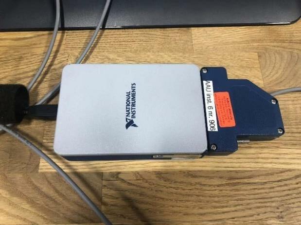
In the case that almost all experimental results cannot be obtained close to the theoretical value, the heat flux sensor used in the test is suspected of being calibrated. The heat flux sensor calibration will be performed by the hot plate, an EPS board and the heat flux sensor. In the hot plate, the heat flux sensor will be placed on the EPS board between the board and the hot side of hot plate. Data is transported through the USB cDAQ from the sensor to module, USB cDAQ and computer.
49
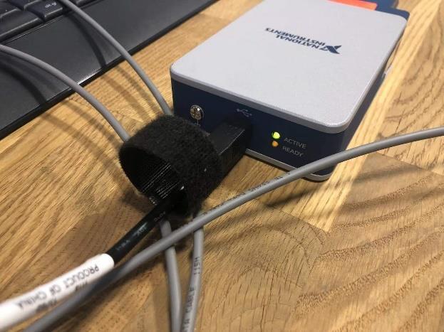
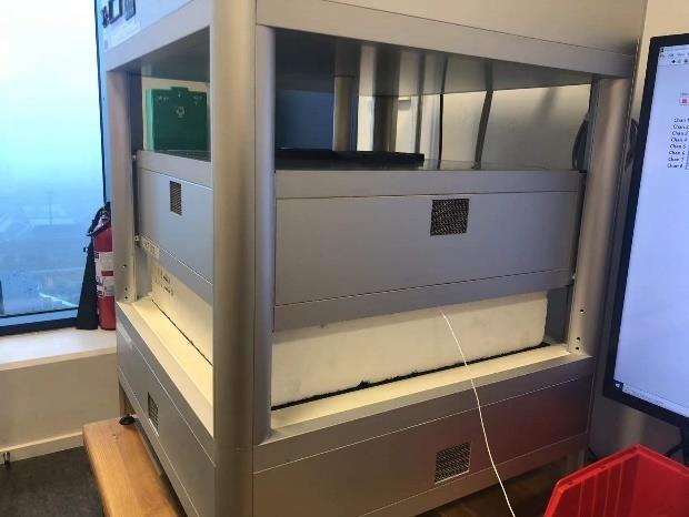
Figure 49 Settings for heat flux calibration
The test in the hot plate shows also wired reading from them the heat flux sensor. After turning on the hot plate, the heat flux sensor located on the EPS board facing the hot side should receive heat energy and generate the positive electricity signal, but according to the recorded data, the heat flux sensor always displays a pretty constant signal with -0.0005. The reason in this situation may because there is a connecting problem, since there is not enough time for further investigation, only further plan for calibration will be described.
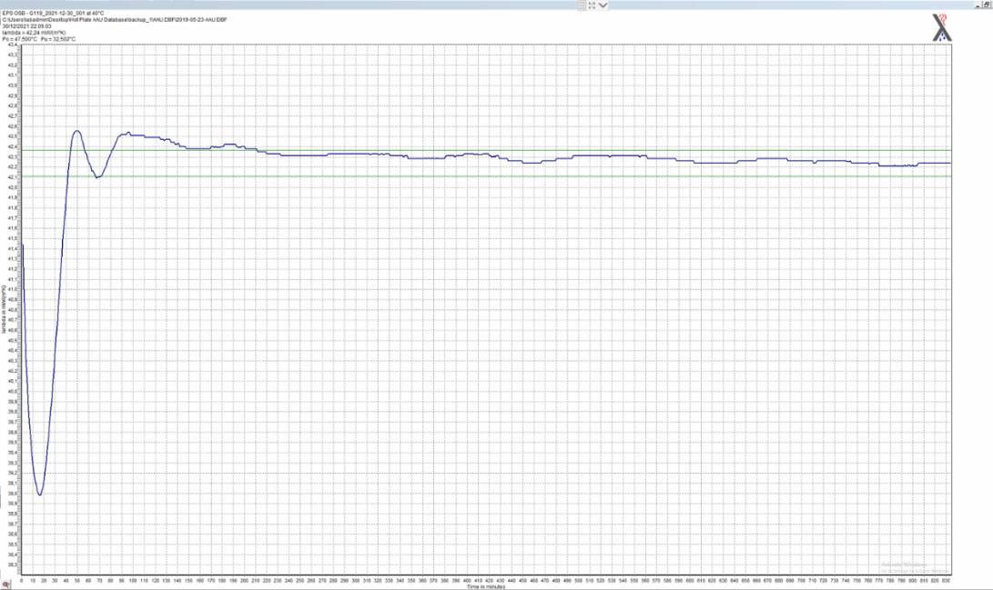
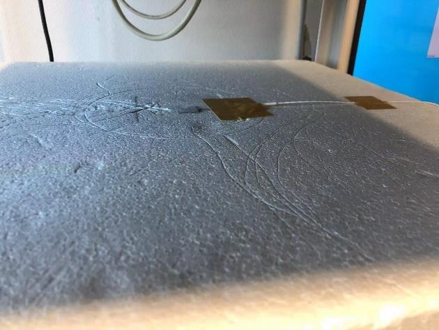
Figure 50 hot plate result picture during the heat flux calibration
Most of heat flux sensor calibration method are using the same laws of physics, the heat flux sensor will be placed on the heat conducting object, then the heat energy will go from the heater to the heat sink, the heating power used by heater will be recorded to divide the area of the heater can calculate the heat flux.
ϕ=
Pℎ���������� ��ℎ����������
50
Where: Φ the heat flux W/m2 Pheater the power used for heater W Aheater the heater surface area m2
The heat flux sensor sensitivity is the ration between the heat flux sensor output voltage and the applied heat flux Φ.
S=
U������ ϕ
Where: S the heat flux sensor sensitivity μv UHFM the output voltage of HFM μv/(W/m2) Φ the applied heat flux W/m2 In (Huskseflux, 2018) it is mentioned the calibration settings based on (ASTM C113017, 2017) that the heat flux sensor (3) can be placed between a heater (2) and a solid material block (mass>1 kg) for calibration for example an aluminum block (5). An insulation layer (1) should be put on the heater to protect the heater and thermal energy. The heat flow (4) will be through the heat flux sensor from the heater to the metal block.

Figure 51 settings for simple heat flux calibration
There are also other methods using different equipment, like (Tsai et al., 2004) states another method using the VTBB. The VTBB (variable-temperature blackbody) is using a thermally insulated graphite tube cavity heated by electricity. This method can heat tube very fast by using the large AC currents at low voltage. In (Jean, et al., 2014) described a method called MEC (Méthode Experimentale pour la Calibration” (in French)), this method will not directly place the sample heat flux on the black painted steel plate infrared bulb lamp but at 7cm for obtaining the more average flux. On another side of steel plate, there are 4 heat flux sensors fixed by the polymethyl-
51


