
SHALTON
Revit
• Families
• BIM360
• CTC
AutoCAD
Adobe Creative Cloud
• Photoshop
• InDesign
• Illustrator
Enscape
Bluebeam
Rhino 3D
• VRay
Microsoft Office
Sketchup
UNIVERSITY OF CINCINNATI
B.S. in Architecture
Class of 2020
Awards & Honors:
EDUCATION INTERESTS
• Cincinnatus Scholar - for academic
• National Outreach Scholar - for
• Dean’s List - for academic merit
• 2020 DAAPWorks Directors' Choice outstanding group architecture
• Regional Alumni Network Scholarship academic merit and extracurricular
• Sketching - architecture, diagrams,
• Cooking - presentation, task
• Music - listening, playing, watching
• Baseball - playing, watching,
• Camping - exploration, problem
• Horticulture - plant care, research
• Model Rockets - model building,
2 CONTACT | E. ELLIS.SHALTON@GMAIL.COM | P. 773.682.4760
EXPERIENCE
INC ARCHITECTURE & DESIGN
New York, NY | Aug 2021 – Aug 2023, Aug 2018 – Dec 2018
Architectural Designer, Architectural Intern
Operated as an architectural and interior design team member on submissions and presentations through SD, DD, and CD on hospitality, residential, resort projects. Designed and produced client-facing deliverables. Contributed in team meetings to develop project deliverables, designs, and firm culture.
• Created, managed, and organized drawings, renders, and workflow tools on several projects throughout the firm to improve efficiency and adaptability for my teams. (Revit, Enscape, Photoshop, Bluebeam, Google Suite, CTC)
• Led research for exterior waterproofing products and fascia materials for multiple single family homes in upstate New York. Managed sourcing and ordering of finish and product samples for interiors projects, prioritizing accessibility and organization.
• Charretted and produced project pitches for residential, spa, and lodge buildings for a ski-in residential community and resort in Utah and a lobby and co-working space in New York City. (Revit, Enscape, Bluebeam, AutoCAD, Photoshop, BIM 360, CTC)
• Successfully collaborated with consultants to address:
• structural requirements for a loft space of a single-family residence.
• zoning, ADA requirement, and code issues on projects in municipalities across New York and Utah.
• material samples for interior finishes and exterior cladding.
• Modeled complex geometries and Revit families across multiple large-scale spaces to provide design elements and context for renders and drawings. (Revit, Rhino)
• Drafted interior detail drawings including millwork, door frame, floor assembly, and partition type details; exterior details including wall and roof build ups, foundation and footing, and window framing details. (Revit)
WRIGHT HEEREMA ARCHITECTS
Chicago, IL | May 2019 – Aug 2019
Architectural Intern
CINCINNATI
academic merit for academic merit merit Choice Award for architecture capstone project Scholarship - for extracurricular involvement diagrams, nature management watching live shows leadership problem solving research building, craft
Worked on specialized design teams for projects in workspace and master planning. Created and updated marketing and firm website content to enhance its portfolio and brand image. Attended industry events to help represent the firm, benefit office culture, and pursue education on design products and services.
• Member of the office recycling team that overhauled the recycling initiative by designing signage, researching improved recycling equipment, and producing presentations for office knowledge. (Photoshop, InDesign, PowerPoint)
• Worked with office BIM manager to create and upgrade Revit families for office standards library.
• Participated in walkthrough and punchlist for a 24,000 SF office space and amenities renovation in Chicago.
• Participated in site visits, staging, and photoshoot of firm projects at multiple renovated commercial atriums in Chicagoland area.
BAUER ASKEW ARCHITECTURE, PLLC.
Nashville, TN | Jan 2018 – May 2018
Architectural Intern
Developed drawingsets for a variety of single-family residential and education projects. Updated content and visual assets for projects. Met with product vendors and representatives to learn about new products for ongoing projects.
• Produced drawings, renders, and other deliverables in DD and CD phases of a new build 14,000 SF secondary education center in southern Tennessee. (Revit, Photoshop, Fotosketcher)
• Improved and updated documentation photographs and renders for numerous projects displayed on the firm’s website, benefitting the company’s portfolio and social media presence. (Photoshop, Fotosketcher)
• Aided in production of pricing set for a 91,000 SF new build academic hall in Tennessee. (Revit)
• Documented existing conditions and measurements for a lobby renovation and addition project at an elementary school in Nashville.
3
AGENDA


4
1 2 3
PROFESSIONAL EXPERIENCE
4 5
ALANG WORKER HOUSING
PENROSE ACOUSTICS
NEIL A. ARMSTRONG ACADEMY
HAND RENDERINGS
5
PROFESSIONAL EXPERIENCE 1

6

1 7

8
NEVELHAUS
PROJECT TYPE
Single Family Residential LOCATION
New York & Connecticut
DESIGN PHASES
Schematic, Construction
Documentation & Construction Administration
PRIMARY RESPONSIBILITIES
• Revit modeling
• Drawingset organization
• Visualization and rendering
• Construction documentation
• Product research
9

NEVELHAUS 60'
This marketing render on the left, displayed at Serhant's SoHo office, shows NevelHaus 60' option with a pool. I styled this render to curate a vibrant, eyecatching image through depth of color and time of day. All
at INC Architecture & Design
work done
NEVELGARAGE
This render that I produced, as seen on the NevelHaus website illustrates the option of a garage in addition to the standalone NevelHaus. It employs the use of shadows and proportion for a more dynamic composition.

more at nevelhaus.com
See
12 All work done at INC Architecture & Design REF. PANTRY DW CL WINDOW CL WINDOW CL WINDOW CL WINDOW CL WINDOW CL DOOR CL WINDOW CL WINDOW CL WINDOW CL CL CL CL PLUMB. CL WINDOW CL WINDOW W D CL WINDOW CL WINDOW CL WINDOW CL DOOR CL WINDOW CL WINDOW CL WINDOW CL WINDOW CL WINDOW C A-202 A1 A-202 A6 A-201 A6 A-201 C1 P. BATH 225 SF PRIMARY BEDROOM PANTRY MECH. PWDR 892 SF LIVING LOFT LOFT TERRACE 68'-3 1/2" 6 '10 1/ 4 " 5 '4 1/ 2 " 4 '0 4 '0 " 8 '2 3 / 4 " 20'-0" P. TERRACE 7 '0 1/ 4 4 '0 9 '4 8 '1/ 2 4'-0" 6'-9" 7'-5 1/4" 4'-0" 4'-0" 10'-0" 10'-0" 5'-1 1/4" 13'-0" 4'-0" A5 A-301 A10 A-301 111 113 112 114 115 123 102 103 A-402 K2 A-404 A1 2 8 '5 1/ 2 4'-0" 6'-2 1/4" 4'-0" 4'-0" 4'-0" 4'-0" 20'-0" 5'-11 1/2" 4'-0" 4'-0" 4'-1 3/4" 4'-0" OUTDOOR SHOWER A-402 A1 A-401 A7 G1 A1 A11 A-401 G11 A-401 G7 A-401 L7 L1 A-403 A3 A1 A10 110 116 121 WIC A-404 F13 A-402 K11 K9 K14 K7 TYP. A7 A-512 D11 A5 A-302 101 CL WINDOW CL WINDOW CL WINDOW CL WINDOW A-404 A13 E Q E Q CL WINDOW CL WINDOW B1 B2 B1 B1 B2 C1 C1 B1 B1 B1 B1 B1 B1 B1 B1 B1 B1 B1 B1 B1 B1 B2 E1 E1 D1 D1 E1 D1 D1 E1 B1 D1 B2 D1 E1 B1 EQ EQ EQ 2 85 1/ 2 8 " 8 8 " FLOOR GRILLE, TYP. SEE MECHANICAL DRAWINGS FLOOR GRILLE, TYP. SEE MECHANICAL DRAWINGS FLOOR GRILLE, TYP. SEE MECHANICAL DRAWINGS EQ EQ MIN. 4'-8" 117 26'-9 1/2" 2'-8 1/8" 4'-6 7/8" 5'-5 1/8" 4'-4 1/2" 15'-1" 29'-5 5/8" 4'-6 7/8" 5'-5 1/8" 4'-4 1/2" 6'-0" 9'-1" 5'-4 1/2" 3'-8 1/2" 5 '2 3 / 4 " 1'3 3 / 4 14 '3 1/ 2 " 1'3 3 / 4 5 '2 1/ 8 5 '6 1/ 4 " 2 '4 1/ 2 5 '9 1/ 2 " 5 '1" 3 '4 1/ 2 3 '4 1/ 2 " 8 '10 1/ 4 " 15 '3 / 4 5 '0 " 2 '4 1/ 2 4 '10 1/ 4 " CL WINDOW EQ EQ EQ EQ EQ EQ EQ EQ EQ EQ EQ EQ EQ EQ EQ EQ 1 1' 1.5 1.6 2 A.5 B A EDGE OF FDN EDGE OF FDN COLUMN C.L. EDGE OF FDN COLUMN C.L. COLUMN C.L. COLUMN C.L. EDGE OF FDN A-201 A6 A5 A-301 A10 A-301 A5 A-302 4' - 0" 60' 3 1/2" 4' - 0" 38 SF BATH 70 859 SF BASEMENT 001 002 003 4'-7" 5'-6 1/2" 4'-5 5/8" 14'-10 3/4" A-405 A1 B2 B2 C1 B1 C1 B1 4 '11 7 8 8 '4 5 / 8 2 '10 1/ 4 " 10 '3 1/ 4 " 15 '4 1/ 4 10 '10 1/ 4 " B1 B1 6'-2 3/8" 4'-0" 4'-0" 4'-0" 4'-0" 20'-0" 5'-11 1/2" 4'-0" 4'-0" 4'-1 3/4" EQ EQ EQ 24'-3 3/4" 4'-6 1/2" 2 3 '1/ 2 3 '4 1/ 2 B1 F1 F1 F1 F1 B1 012 010 011 008 009 006 120 12 SF MECH. 10 SF MECH 334 SF BEDROOM 33 SF STOR. 94 SF LAUNDRY 44 SF CLOSET B1 1 1' 1.5 1.6 2 A.5 B A EDGE OF FDN EDGE OF FDN COLUMN C.L. EDGE OF FDN COLUMN C.L. COLUMN C.L. COLUMN C.L. EDGE OF FDN GENERAL 1. FLOOR 2. CE L N 3. CE L N DEVICES 4. F N SH MARKERS 5. WATE WALLS. 6. POWE 7. SLAB SAFING 8. PROVIDE 9. EXISTING 10. ALL CABINETRY PER ARCHITECTURAL 11. DURING COVERED 12. ALL GLASS TEMPERED 13. ALL MIRRORED 14. ANY SHAFT CONDITION 15. FOR WINDOW 16. LOCATE 17. LOCATE BUILDING 18. FOR DEPARTMENT E R N 19. PRICE 20. PROVIDE LIMITED BE PATCHED REPLACED. 21. NOT ALL ARCHITECTURAL CONJUNCTION ELECTRICAL 22. PATCHED APPEARANCE, OR BREAK 23. FOR MILLWORK 24. ALL DIMENSIONS 25. DIMENSIONS LEGEND AA000 1i 1t H-101 TYPICAL EQ MIN. 4" LEGEND 123456789 10 11 12 13 A B C D E F G H I J K L M N P 123456789 10 11 12 13 9 / 2 / 2 0 2 2 8 :18 :3 6 P M 1/4" = 1'-0" H2 CONSTRUCTION PLAN -1ST FLOOR 1/4" = 1'-0" A2 CONSTRUCTION PLAN -WALKOUT REF. PANTRY DW GFI GFI GFI S 3D 3 S 3 D 3 D 3 S S 3 S SS S SS D S C C GFI GFI GFI C GFI J J T T T S CL CL CL C 6 P D M S T J P. BATH PRIMARY BEDROOM PANTRY MECH. PWDR LIVING LOFT LOFT TERRACE P. TERRACE A-404 A1 A-402 A1 WIC 2 '0 6" 5 1/ 8 " 2 '5 5 / 8 3 '0 7 / 8 " E Q E Q EQ EQ 6" 5 1/ 4 6 6" 6" 6 " 1'10 " 1' 3" 210 1/ 2 " 1' - 1" 2' - 3" 1' - 1" 2' - 3" 8 1' 6 1'9 22 30 40 11" 6" EQ EQ 6 " EQ EQ EQ EQ 6 1' - 2" 1' - 2" 6" EQEQ E Q E Q E Q E Q A-402 K2 6 " 6" EQ EQ 10'-6" 4 '8 1/ 4 9'-4" 8 '0 " E Q E Q LEGEND LEGEND 8 8" 4" GENERAL 1. 2. 3. 4. 5. H J K L M N P 123456789 10 11 12 1/4" = 1'-0" A2 POWER/DATA PLAN -1ST FLOOR main floor construction plan main floor power/data plan COORDINATION FLOOR PLANS & WALL SECTION DETAILS
See more at
The coordination plans, wall section, foundation, and footing details on these pages are samples from multiple construction and filing drawingsets of which I had a primary role in drafting, managing, detailing, and coordinating.
13 C DOWN SPOUT ALIGN ALIGN METAL WALL FINISH, AS SPECIFIED J CHANNEL, FINISH TO MATCH WALL CONCRETE FOUNDATION, SEE STRUCTURAL DRAWINGS CONTINUOUS CUSTOM METAL PROFILE, FINISH TO MATCH WALL 10" DOWNSPOUT T&G WOOD PANELING AS SPECIFIED FOUNDATION WALL, SEE STRUC. AIR SEAL EARTH PARTITION, AS SPECIFIED 5/8" GYPSUM WALL BOARD FLOOR FINISH AND ASSEMBLY, AS SPECIFIED BASEBOARD, AS SPECIFIED PLYWOOD SHEATHING, SEE STRUCT. FILL CAVITY W/INSULATION SLAB ON GRADE, SEE STRUC. GRAVEL FILL FLASHING 2X8 WOOD STUD 3" INSULATION, H275 VAPOR BARRIER 5/8" GYPSUM WALL BOARD 2X10 WOOD JOIST, SEE STRUC. INSULATION BETWEEN TRUSS MEMBERS 2X6 SILL PLATE W/SILL SEALER, SEE STRUC. 1/2" FURRING STRIPS 16" O.C. STRUCTURAL REBAR, SEE STRUC. T.O. GRADE T.O. F.F. 6 2 M IN 6 M IN T.O.S. HYDRODUCT 220, TM 77 GROUNDBREAK FRP SHEET ADHERERD TO INSULATION, P 958 EXTERIOR SHEATHING, SEE STRUCT. 1X FURRING STRIPS ROUTED OUT FOR DRAINAGE, 16" O.C. PREPRUFE 800PA, M28 2" INSULATION PERM-A-BARRIER VPL, TM36 2" INSULATION PERM-A-BARRIER WALL FLASHING, M36 T.O. SLAB ON GRADE PREPRUFE 800PA, M28 2X4 SILL PLATE T.O. FOUNDATION (3) 2x10 LVL BEAM, SEE STRUC 2X10 RIM JOIST, SEE STRUC. 1/2" INSULATION GREENGIRT Z-CLIP, SEAL AROUND ALL PENETRATIONS GREENGIRT Z-CLIP, SEAL AROUND ALL PENETRATIONS 5/8" 7 1/2" 1/2" 2" 1/2" 3/4" CONTINUOUS CUSTOM METAL PROFILE, FINISH TO MATCH WALL METAL WALL FINISH, AS SPECIFIED T.O. GRADE T.O. F.F. 8 M IN 6 M IN T.O.S. FOUNDATION WALL, SEE STRUC. HYDRODUCT 220, TM57 EARTH PARTITION, AS SPECIFIED 5/8" GYPSUM WALL BOARD FLOOR FINISH AND ASSEMBLY, AS SPECIFIED BASEBOARD, AS SPECIFIED PLYWOOD SHEATHING, SEE STRUCT. GROUNDBREAK FRP SHEET ADHERED TO INSULATION, PL95 FILL CAVITY W/INSULATION 2X6 WOOD JOIST EXTERIOR SHEATHING, SEE STRUCT. 3" INSULATION, H275 2X10 WOOD JOIST, SEE STRUCTURE INSULATION BETWEEN TRUSS MEMBERS VAPOR BARRIER 1X FURRING STRIPS ROUTED OUT FOR DRAINAGE, 16" O.C. PREPRUFE 800PA, TM 8 2" INSULATION STRUCTURAL REBAR, SEE STRUC. 6 2 O V E R L A P PERM-A-BARRIER VPL, M PERM-A-BARRIER WALL FLASHING, M 62 METAL FLASHING FITTED TO TOP OF CUSTOM METAL PROFILE, FINISH TO MATCH WALL PREPRUFE 800PA, TM 8 T.O. FOUNDATION 2x4 SILL PLATE 2X10 RIM JOIST, SEE STRUC. 2" INSULATION 1 1/2" INSULATION LINE OF J METAL TRIM BEYOND GREENGIRT Z-CLIP, SEAL AROUND ALL PENETRATIONS GREENGIRT Z-CLIP, SEAL AROUND ALL PENETRATIONS 5/8" GYPSUM WALL BOARD 1/2" FURRING STRIPS 16" O.C. AIR SEAL SHEET ID SHEET TITLE REVISIONS PROJECT TEAM PROJECT OWNER NOTES KEY PLAN ARCH ECTURE INC ARCHITECTURE & DESIGN, PLLC 150 VARICK ST, FLOOR SOUTH NEW YORK, NY 10013 T: (212) 673-1695 F: (212) 625-2053 INFO@INC.NYC MEP COLLECTIF ENGINEERING, PLLC 3955 51ST STREET, 1B WOODSIDE, NY 11377 T: (857) 654-7739 INFO@COLLECTIFE.COM No: A B C D E F G H J K L M N P 123456789101112131415 A B C D E G H K M N P 123456789101112131415 NOT FOR CONSTRUCTION 9 2 2 0 2 5 :5 4 :3 P M DETAILS -EXTERIOR (@ NEVELHAUS 60' -GOSHEN 2011 THE NEVELHAUS COMPANY LLC INFO@NEVELHAUS.COM A-502 .00 3" = 1'-0" J12 ELEVATION DETAIL -GABLE END SILL 3" = 1'-0" A2 SECTION DETAIL -WALL -SILL @ SLAB ON GRADE 3" = 1'-0" A10 SECTION DETAIL -WALL -SILL FOUNDATION @ GRADE NO.NAME 00VERSION L CL WINDOW DOOR, AS SPECIFIED FOUNDATION WALL, SEE STRUC. PARTITION BEYOND FLOOR FINISH AND ASSEMBLY, AS SPECIFIED CONTINUOUS CUSTOM METAL PROFILE, FINISH TO MATCH WALL T.O. GRADE T.O. FOUNDATION 8 M IN 6 M IN BASE BEYOND WEATHER SEAL SLAB GRADE, SEE STRUC. 6" GRAVEL FILL 1/2" EXPANSION JOINT HYDRODUCT 220, TM57 EARTH PLYWOOD SHEATHING, SEE STRUCT. PARTITION, AS SPECIFIED PREPRUFE 800PA, TM 8 3" INSULATION, TH2 5 STONE OR PRECAST STEP DOWELS 2X10 WOOD JOIST, SEE STRUC. WOOL INSULATION BETWEEN TRUSS MEMBERS 2" INSULATION STRUCTURAL REBAR, SEE STRUC. GROUNDBREAK FRP SHEET ADHERED TO INSULATION, PL95 APPLY SEALANT CONTINUOUSLY AROUND WINDOW PERIMETER PERM-A-BARRIER WALL FLASHING OVER METAL FLASHING, TM 62 METAL FLASHING WITH 3 SIDED UPTURN SHOP WELDED AND FLASHED OVER WITH PERM-ABARRIER FLASHING MEMBRANE METAL ANGLE, SEE STRUC. PREPRUFE 800PA, TM 8 T.O. F.F. T.O.S. PREPRUFE TAPE, TM282 PREPRUFE 800PA TO ENCAPSULATE TAPING BEHIND OF FOUNDATION WALL 3/4" OFFSET FROM EXTERIOR GREENGIRT Z-CLIP, SEAL AROUND ALL PENETRATIONS 8 / 0 SLOPE 8 /1 0 S OPE 2x4 SILL PLATE 2X6 SILL PLATE W/SEALER, SEE STRUC. 5/8" GYPSUM WALL BOARD 1/2" FURRING STRIPS 16" O.C. WINDOW, AS SPECIFIED FOUNDATION WALL, SEE STRUC. PARTITION BEYOND FLOOR FINISH AND ASSEMBLY, AS SPECIFIED CONTINUOUS CUSTOM METAL PROFILE, FINISH TO MATCH WALL T.O. GRADE T.O. FOUNDATION 8 M IN 6 M IN T.O.S. PAINTED TRIM BASE BEYOND WINDOW TRIM BEYOND WEATHER SEAL AIR SEAL HYDRODUCT 220, TM57 EARTH PLYWOOD SHEATHING, SEE STRUCT. 2X10 WOOD JOIST, SEE STRUCTURE INSULATION BETWEEN TRUSS MEMBERS PARTITION, AS SPECIFIED 3" INSULATION, TH275 2X6 SILL PLATE W/SILL SEALER, SEE STRUC. GROUNDBREAK FRP SHEET ADHERED TO INSULATION, PL95 STRUCTURAL REBAR, SEE STRUC. APPLY SEALANT CONTINUOUSLY AROUND WINDOW PERIMETER PERM-A-BARRIER WALL FLASHING OVER METAL FLASHING, TM 62 METAL FLASHING WITH 3 SIDED UPTURN SHOP WELDED AND FLASHED OVER WITH PERM-ABARRIER FLASHING MEMBRANE PREPRUFE 800PA, TM 8 T.O.F.F. OF FOUNDATION WALL 1/8" OFFSET FROM EXTERIOR 2" INSULATION 1/2" INSULATION GREENGIRT Z-CLIP, SEAL AROUND ALL PENETRATIONS PREPRUFE 800PA, TM 8 2X4 SILL PLATE 2x10 RIM JOIST, SEE STRUC. 5/8" GYPSUM WALL BOARD 1/2" FURRING STRIPS 16" O.C. SHEET ID SHEET TITLE REVISIONS NOTES KEY PLAN INFO@INC.NYC MEP COLLECTIF ENGINEERING, PLLC 3955 51ST STREET, 1B WOODSIDE, NY 11377 T: (857) 654-7739 INFO@COLLECTIFE.COM A B C D E F G H J K L 123456789101112131415 A B C D E F G H J K L NOT FOR CONSTRUCTION 9 2 2 0 2 5 :5 4 :3 6 P M DETAILS -EXTERIOR A-503 .00 3" = 1'-0" A9 SECTION DETAIL -ENTRY DOOR -SILL 3" 1'-0" A2 SECTION DETAIL -WINDOW -SILL 1ST FLOOR @ GRADE NO.NAME 00VERSION
nevelhaus.com

14
UTAH SKI COMMUNITY
PROJECT TYPE
Resort, Hospitality, Residential
LOCATION
Provo, Utah
DESIGN PHASES
Preliminary through Schematic
PRIMARY RESPONSIBILITIES
• Design charetting
• Drawingset organization
• Revit modeling
• Enscape visualization
• BIM 360 collaboration
15

16 All work done at INC Architecture & Design
SKI & ADVENTURE CENTER RENDER

17
A selection of drawings and diagrams from the project's schematic design phase pricing set that I had a consistent role in modeling, drafting, detailing, and researching.


winter solstice fall equinox
18 All work done at INC Architecture & Design OPEN TO BEYOND OPEN TO BEYOND OPEN TO BEYOND OPEN TO BEYOND OPEN TO BEYOND OPEN TO BEYOND OPEN TO BEYOND UD UA UC UB 00.1 F.F. 0' - 0" 01.0 T.O.S 14' - 10" 01.1 F.F. 15' - 0" 02.0 T.O.S. 29' - 10" 02.1 F.F. 30' - 0" 03.0 B.O.ROOF 44' - 10" 02.7 B.O. CLG 42' - 0" 00.7 B.O.CLG 11' - 0" 01.7 B.O.CLG 26' - 0" 01.2 T.O. LOWER POOL 17' - 0" 03.1 T.O.ROOF 54' - 8" A1 A-301 150 SF VESTIBULE 715 SF ENTRY SEQUENCE 97 SF MINISTORE 95 SF GM OFFICE 235 SF KITCHEN 1207 SF DINING/MULTIPURPOSE 759 SF LOCKERS 528 SF CIRCULATION 1802 SF GAME ROOM 697 SF BIKE & OUTDOOR STORAGE 1289 SF ADVENTURE CENTER LOUNGE W.02 B.51 C.21 S.02 S.11 S.15 W.01 G.02 G.20 W.01 C.21 W.02 S.02 B.51 S.15 J.01 R.01 C.21 G.13 G.13 G.13 G.20 R.04 P.01 M.04 M.04 G.20 R.03 C.21 W.12 W.08 S.15 W.08 B.51 9'-10" 2'-10" 12'-0" 4'-0" 11'-0" 4'-0" 11'-0" 1/8" = 1'-0" J1 SECTION -LONGITUDINAL DRAWING SAMPLES
All work done at INC Architecture & Design
section
exposure studies
longitudinal
solar
equinox
summer solstice spring
19 W C. W C W C W C DN DN A-202 A1 A-202 I1 J1 A-201 A1 U4 UD U1 UA U2 U3
U6 U5 25'-0" 20'-0" 25'-0" 12'-0" 15'-0" 19'-6" 25'-0" 8'-5 5/8" 387 SF COMISSARY/ STORAGE 715 SF ENTRY SEQUENCE A1 A-301 J1 A-301 150 SF VESTIBULE 95 SF GM OFFICE 97 SF MINISTORE 164 SF BOH MECHANICAL 235 SF KITCHEN 140 SF MAIL/PACKAGE 466 SF MEETING/PDR 40 SF FIRE RISER 60 SF COATS 1207 SF DINING/MULTIPURPOSE SKYLIGHT ABOVE SKYLIGHT ABOVE ROOF ABOVE COAT STORAGE: 332 IN. H.20 M.03 G.13 M.02 S.03 J.01 S.20 S.20 70'-0" 60'-5" 87'-4" 80'-0" S.11 S.11 S.11 S.11 H.92 B.51 B.51 S.02 S.02 H.21 B.51 S.15 S.16 B.51 S.11 S.11 S.15 main floor schematic plan
UC UB

20
MIDTOWN HOTEL
PROJECT TYPE
Hospitality
LOCATION
New York, New York
DESIGN PHASES
Model Room:
Schematic through Construction
Amenity Spaces:
Preliminary through Design Development
PRIMARY RESPONSIBILITIES
• Revit modeling
• Construction Administration
• Designing to brand standards
• FF&E selection
21
A variety of deliverables from the schematic, design development, and construction phases of the project. I worked on these on producing these deliverables, particularly in the modeling, drafting, visualization, and presentation.


22
work done at INC Architecture & Design MIDTOWN HOTEL MODEL ROOM
All
C SS GFCI P S SSS CL CL BED CL CL CORRIDOR CL MODEL ROOM ENTRY CL CL SC C 5 H V ID-401G 10 7 8 11 ID-401G 1 2 ID-401G 4 3 6 5 ID-402G 1 3 2 4 RF135A PB201 CP103 TL302A PB206 PB870 ID-401G 9 ST687 103 101 ST687 PB635 4'-0" PROVIDE PLYWOOD SUPPORT FOR UPHOLSTERED BENCH RAJACK HINGES FOR REAR MTD. DOOR ST687 TL302 ALT. ALT. ST687A RF135 ALT. ALT. PB870A +52" +52" REF PLUG-IN ARMOIRE LIGHT (JAMB SWITCH) DUPLEX FOR ARMOIRE LIGHT AND REFRIDGERATOR, SEE ELEV. QUAD FOR ARM FIXTURE, READING LIGHT, POWER PACK AND PHONE QUAD: (1) SWITCHED OUTLET FOR LINEAR HEADBOARD LIGHT, (3) OUTLETS FOR READING LIGHT, GLOBE LIGHT AND POWER PACK PLUG-IN SCONCE PLUG-IN SCONCE PLUG-IN HEADBOARD LIGHT DATA PORT FOR PHONE NOTE: REFER TO LIGHTING DESIGNER'S DRAWINGS FOR SITCHING AND CIRCUITING WAP BEHIND TV 2'-0" EQ EQ 1'-5" 1'-3" 11" 4'-1 1/2" 3 3/4" 4'-1" SP635 QUEEN 1.6 RM-09 TOILET / SHOWER LOCATE IN FIELD WITH ARCHITECT 5" 1'-6" 1'-10" EQ EQ 5'-3 3/4" EQ EQ 4" 2'-0 3/4" 3 1/4" OUTLET IN STONE SIDESPLASH, SEE ELEV. FLOORING TO CONTINUE UNDER BENCH TO WALL DSK002 T HW625 9' - 2 1/2" 8' 7' - 10" 7' - 10" PT150 SURFACE MOUNTED DRAPERY TRACK, SEE FF&E PACKAGE PROVIDE BLOCKING DR326 PT150 MT250 5 1/2" 3" 1'-0" 1'-8" 3'-0" 9" EQ EQ EQ EQ LT767 LT767 PROVIDE SINGLE GANG HANDY BOX FOR SCONCES SEE ELEVATION FOR ORIENTATION ME305 ME305 2'-0" FINISH LEGEND LUXURY VINYL TILE CARPET TILE CEILING LEGEND DECORATIVE LIGHT, TO BE WIRED AS A JUNCTION BOX UP LIGHTING, TO BE HARDWIRED RECESSED DOWN LIGHT, TO BE HARDWIRED DECORATIVE SCONCE, TO BE WIRED AS A JUNCTION BOX SMOKE AND CARBON MONOXIDE DETECTOR AS SPECIFIED CEILING SPRINKLER HEAD ACCESS PANEL WALL MOUNTED SPRINKLER HEAD MIN (EQ) LEGEND - POWER DATA LEGEND VIDEO COAXIAL CABLE - TV CAT 5 HDMI RANGE OUTLET SHADE WIRING SINGLE OUTLET SPECIAL OUTLET 1/2" = 1'-0" 2 PLAN FINISH / CONSTRUCTION / POWER/DATA -MODEL ROOM 1/2" = 1'-0" 1 PLAN CEILING -MODEL ROOM constructed model room model room render model room floor plan


23 colored guest suite elevations


gallery fitness


This is a selection of renders and accompanying DD plan which I worked on the modeling, drafting, and rendering processes for. These deliverables were significant in the finish selection, lighting, and FF&E development of these spaces.


MIDTOWN HOTEL AMENITIES
PE-A1 PE-A2 PE-A3 PE-A4-402 -402-402 -402 12-409 FITNESSCORRIDOR -10 ELEVATOR LOBBYGALLERYWOMEN'S RESTROOMMEN'S RESTROOMRESTAURANTBOH CORRIDORTERRACE HALLWAYAREA TO BE ISSUED AT LATER DATE TL165 TL165 TL161 -402 -409 RF133 RF133 MT123 TF156 TF156 TF156 DA14 DA13.1 DA10 DA13.1 MT194 MT194 5'-4 3/4" TL161 TF156 TF156-551-551 MT202 MT202 FINISH NOTES PREP EXISTING WALLS FOR PAINTING AS REQUIRED- PATCH, SAND SKIM COAT ANY UNEVEN SURFACES. ALL EXISTING MOLDINGS AND TRIMS TO REMAIN SHALL RECEIVE LIGHT TO MEDIUM SAND TO REMOVE PROVIDE SLAB IMAGES FOR ARCHITECT APPROVAL PRIOR TO INSTALLATION. SEE ARCHITECT'S DRAWING FOR WATERPROOFING SPECS AND DETAILS. FIELD WITH ARCHITECT/INTERIOR ARCHITECT. NOTES - POWER DATA NOTES BOXES IS NOT PERMITTED. ALL DIMENSIONS ARE MEASURED FROM FINISHED SURFACES U.O.N. GANG ADJACENT OUTLETS/SWITCHES/JACKS ON SAME PLATE. ALL WALL PLATES FOR OUTLETS, DIMMERS, SWITCHES SHAL BE SCREWLESS. COLOR SHALL BE SELECTED BY ARCHITECT/INTERIOR ARCHITECT. DRAWINGS. PATCH, REPAIR AND CONCEAL ALL HOLES AT RELOCATED RECEPTACLES. LOCATIONS OF ALL EXISTING TO REMAIN RECEPTACLES AND SWITCHES TO BE VERIFIED IN FIELD. ALL WET LOCATION ELECTRICAL RECEPTACLES TO BE GFCI PROTECTED AS REQUIRED PER CODE. FINISH LEGEND WOOD FLOORING CARPET TILE RUBBER FLOORING NOT SCOPE FIFTH AVENUE CIVIL ENGINEER BPP CONSULTANT: ELEVATOR CONSULTANT: 120 Eagle Rock Ave., Suite 310 EAST HANOVER, NJ 07936 TEL.: (973)994-9220 LIGHTING CONSULTANT: FOOD SERVICE CONSULTANT: Longman Lindsey Accoustical ENGINEERS NEW YORK, NEW YORK 10036 (212) 315 6400 EXTERIOR ENVELOPE CONSULTANT: ZONING CONSULTANT: Development Consulting Services, INC. NEW YORK, NEW YORK 10036 (212) 714 0280 Langan Engineering, and Landscape 300 KIMBALL DRIVE, 4TH FLOOR PARSIPPANY, NJ 07054-2172 TEL.: (973) 560-4900 FAX.: (973) 560-4901 Steven Winter Associates, 307 Seventh Avenue Suite 1701 (212) 564-5800 AJL&P Surface TEL.: (212) 757-5659 BUILDING CODE CONSULTANT: CODE, LLC NEW YORK, NEW YORK 10013 (212) 766-8100 32 WEST 48TH NEW YORK, 32 W. 48TH Van Deusen & vda GACE AKF N47 ASSOCIATES Architects,SLCE TEL. (212) 979-8400 FAX (212) 979-8387 1359 BROADWAY, 14TH FLOOR ARCHITECT OF RECORD: KEY PLAN: PROJECT: DRAWING TITLE: STRUCTURAL ENGINEER: MECHANICAL ENGINEER: TEL. (212) 712-6000 NEW YORK N.Y. 10022 805 THIRD AVENUE, 7TH FLOOR OWNER DEVELOPER: PROJECT: TEL. (212) 545-7878 NEW YORK N.Y. 10016 105 MADISON AVENUE TEL. (212) 389-2671 NEW YORK, NY 10006 C/O EXTELL DEVELOPMENT COMPANY INTERIOR DESIGNER: LANGAN Description Project No. ID-102 PLAN FINISH 1/4" 1'-0" 1 FINISH PLAN -LEVEL 02 entry lobby fitness center restroom elevator cab second floor finish plan

26
MIDTOWN WORKSPACE
PROJECT TYPE
Amenity and Co-Working Spaces
LOCATION
New York, New York
DESIGN PHASES
Preliminary
PRIMARY RESPONSIBILITIES
• Concept design & carretting
• Collaboration with renderer
• Finish selection
• Revit modeling
• Plan diagramming
27

work done at INC Architecture & Design
All

desire lines


MIDTOWN WORKPLACE LOBBY
Displayed are a set of deliverables that I worked heavily on the modeling, production, and quality control of. These were part of the initial project proposal to the client group. The diagrams illustrate the design strategies that inform the layout of the schematic lobby blocking plan below.
The render to the left is one of three that illustrate the lobby and bar design. In advising the renderer, I worked on conveying the luxury of the space through the elegant materiality, curved language, and visual access to the exterior.

29
INC Architecture & Design PLANS 2.1 Seat Counts: Lobby: 13 Casual Lounge: 43 Executive Lounge: 84
diagonal motif
view corridors
groundfloor blocking plan
ELEVATED CO-WORKING LOUNGE
Shown below is a schematic blocking plan I modeled and produced, focusing on compartmentalization of space and centralizing circulation at the building core. On the right are renders that I designed, advised, and redlined for the thirdparty renderer. Employing a similar language to the render of the lobby, this space prioritizes the perimeter of the plan to maximize access to views.

30 All work done at INC Architecture & Design Design 61 31 Room(s): 80 (40 per room) Restaurant: 82
amenity floor blocking plan

 amenity floor reception
co-working lounge
amenity floor reception
co-working lounge
ALANG WORKER HOUSING 2

32

33
URBAN SCRAPYARD
Alang, India is home to the world's largest shipbreaking yard which is responsible for breaking down over fifty percent of the world's decommissioned commercial ships. Built around the industry, the town's main provision is worker housing. However, shipbreaking is an extremely hazardous practice. Poor conditions and lack of safety measures in Alang pose further risks to the health of the workers.
Combined with the underprivileged housing and infrastructure, living and working conditions in Alang are unsustainable and unethical. Re-imagined in cooperation with twelve other students, the Alang masterplan strives to provide a more humane, efficient, and ecofriendly option for workers to live and operate in.

34

35
FROM SHIP TO STRUCTURE
The second and primary phase of the project is an exploration in creating a sustainable, ethical, unassuming housing community for workers in the shipbreaking industry. Constructed using recycled elements from decommissioned ships, the structures and their units promote sustainability, affordability, and social interaction.

Rectangular floorplates are stacked and supported by steel frames. These host the units. The units differ in size, shape, material, and capacity and are strategically arranged on each floorplate. Floorplates vary in dimension to create unique moments among the structures. Communal spaces constructed of similar recycled ship materials provide public activity spaces for residents to use and socialize in.
36


37
I - reconstructed
shaded agriculture
activity wells greenspace
static
HOUSING UNITS
II - half pipe III - cylinder
COMMUNAL SPACES
IV - cabin V - wrapped VI - assembled
THE SPACE BETWEEN
The typical floor plate is divided into thirds and units are arranged in various ways to create and enhance interstitial spaces, improve airflow through the structures, and promote individuality from unit-to-unit and floor-to-floor.
In addition, unique arrangements and combinations of units allow for diversified circulation and inhabitation. The aggregation of units also allows the structure to become more sustainable.
To accommodate the arid climate of Alang, units and their arrangements employ numerous passive cooling strategies. Units use screened openings that are conducive to airflow, stacked floorplates that provide shading for floors below, and open-air layout to create a highly sustainable design.
38
accessibility
foliage
circulation v static airflow
39
A COMMUNITY WITHIN
In an industry such as shipbreaking, a vital part in the well-being of the personal spaces balanced with diverse, the forefront of fostering a humane of the units, structures, and community option that excels for the workers of Alang. of recycled ship material greatly enhances and efficiency of the project.

WITHIN THE COMMUNITY
shipbreaking, the element of home becomes workers. Having adequate, private, diverse, interactive social spaces is at living environment. The uniqueness community spaces combine for a housing Alang. Additionally, the prevalent use enhances the sustainability, affordability,

41
3 PENROSE ACOUSTICS


SOUND & STRUCTURE
Designed in conjunction with Masters of Composition students at the University of Cincinnati, this project explores the relationship between soundwave behavior and material properties. The collaboration wrote and iterated scripts in Java to simulate interactions between soundwaves and various materials. The interaction between the simulated sound agents and the selection of materials and their arrangements became the primary driver for a design of a realistic structure. Additionally, the composers wrote pieces to be performed within the completed structure. This stimulated constant creative exchange between the architects and composers that drove the design as well as developed the music.


Architects: Ummul Buhari-Mohammed, Mitch Hoffman, Seanna LaGanke, Michael Rick, & Ellis Shalton
Composers: Yunze Mu & Ye Zhao


44
reflection
contour
materiality


45
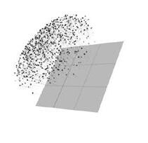
Voxelization is the process of translating data into a 3D mesh based on the information in a given instance. Directed by the behavior of simulated sound agents, voxelization was used to create the unit within the system. These units became the medium to host the varying materials.

46
REFLECTION & VOXELIZATION
The form of the folly as developed with the intent to create areas where the sound can be experienced directly, reflected, or interstitially between the two hosts.

47
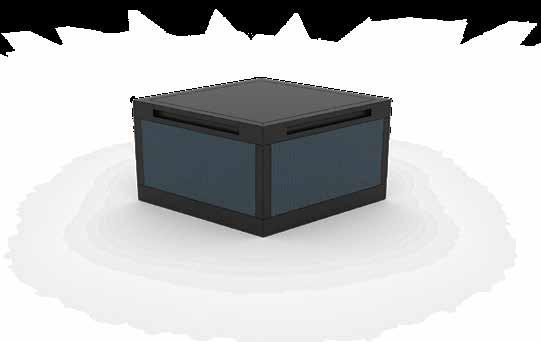
THE ANATOMY OF THE UNIT
In exploring the most versatile, effective way to display and employ all three materials, the unit's form became an extruded rhombus. The angled forms allow for the units to be stacked, aligned, arrayed, and fit to each other seamlessly and universally. Adjacent and stacked units are connected by brass bands that snap into the units. Brass is distinct from the three main materials in appearance and its material characteristics. Its role in the project's tectonics celebrates the element of connection and structure.


48


49 1/2” plywood panel 1” diameter band attachment recepticle 1/8” metal L-shaped bracket 1” flush-head bolt 7/16” metal hex nut 1” metal support 1” metal support 1” melamine foam 1” diameter band attachment recepticle 1” metal support 1” diameter band attachment recepticle
wood
foam composite
foam composite assembly
wood assembly
concrete

simulated sound agents reacting to structure design

interior perspective


A SCULPTED EXPERIENCE
In order to direct and experience the sound's behavior in the desired way, the three materials were aggregated to highlight experiences in certain parts of the folly. For example, the two main coves are defined by concrete units in order to reflect as much sound as possible. Contrastingly, small pockets on the outside of the structures provide quiet, static spaces using foam composite units. As you interact and inhabit the structure, you experience the composers' pieces in various ways.
wood foam composite52
concrete
Quiet Area of Site
Foam Units to Absorb Sound
Transition from Noisy to Quiet
Wood Units to Partially Absorb and Partially Reflect Sound
Noisy Area of Site
Concrete Units Reflect Sound
The folly is designed to be displayed at McMicken Commons at the University of Cincinnati. The site is advantageous to the use of the structure because it is accessible, visible, and centralizes the structure in an area of heavy foot traffic.
53

54

55
ARMSTRONG ACADEMY 4

56

57
58
WEST END, CINCINNATI
Nearly 3,000 people reside in the neighborhood of West End, Cincinnati. Located between the central business district and I-275, nearly half of its residents live below the poverty line. While the area is undergoing many projects that are aimed to address its residents' problems, it still faces a lack of access to education, adequate housing, and businesses. The population density of the neighborhood is nearly three times that of the city of Cincinnati and compounds the problem of overpopulation with these dilemmas. This project is part of a campus that provides an elementary school, an apartment building, and an office complex for the neighborhood and surrounding area. The campus is designed with the goal of net-zero construction. All three buildings operate sustainably on both individual and collaborative levels, employing numerous environmentallyfriendly design strategies.
59
CAMPUS LIFE
The net-zero campus is comprised of two schools, a mixed-use complex, and an office expansion. A landscaped park unifies the three facets by providing essential, versatile greenspace for the campus inhabitants.
As a main part of the effort towards sustainable operation of the campus, there is a geothermal well system beneath the campus greenspace and a geothermal storage tank beneath the northwest parking lot. These systems cooperate to heat and cool the buildings on campus. Storage and transmission of the water through the systems is conducted underground because the ground beneath the frostline better maintains the desired water temperature year-round.
The final prominent aspect of the campus was the traffic flow of automobiles on a daily basis. Traffic studies and thorough analysis led to solutions such as a bus-only lane to service the schools, a local avenue through the middle of the campus to increase accessibility and better define different spaces, and strategic parking areas for each building on campus.
60
61 Office Junior High School Multi Family Elementary School Clark Street West Court Street Cutter Street Cutter Street Mound Street 50 150 350 0 ft.
A SCHOOL FOR THE MODERN DAY
The design prioritizes efficient use of space, orientation, and innovative design strategies to set the project apart from traditional education projects. The site provides a limited footprint, which prompted the move to build "up" instead of "out" and to arrange program creatively. For example, the playground that occupies the third floor not only minimizes the school's footprint, but it also provides a more secure environment for students, a more accessible location, and exceptional insulation for the spaces below. Sustainable design features include photovoltaic panels and solarthermal tubes arrayed on the facades and roof, shading devices, and a storage system for rainfall runoff stored in the specially designed west wall of the building.
Architect: Ellis Shalton
Architectural Engineers: Jenn Adamec, Kerry Baza, & Seth Richenbach
Civil Engineers: Greta Antonetz, Ben Blacklidge, Jenny Engels, Lucas Eshbaugh, & Jeremy McQuilkin


62

first floor
second floor

third floor
EASE OF ACCESS
Classrooms are organized in an "L" shape occupying the southeast corner of the building. Program is centralized around the circulation space on each floor. This creates a straightforward layout that minimizes the distance between rooms -- helpful when ushering students between spaces.
DAYLIGHTING
The layout of each floor is designed to be "transparent" from endto-end utilizing open areas and glass partitions. This is essential in maximizing the amount of daylight that reaches the innermost parts of the building. It also allows the building to feel more open, inviting, and approachable.
COMPARTMENTALIZATION
Compartmentalization has become a necessity in many of today's public spaces. This project compartmentalizes the building using deployable barriers in circulation spaces. These barriers and subsequent compartments of the building serve not only as measures against active threats inside buildings, but also to combat other emergencies such as fires and missing students.
64


65

 second floor creative space
66
kindergarten classroom


playground third floor creative space 67
HAND RENDERS 5

68

69
PROUNS
The effort in the Prouns to conceptualize dimensional view shape study and perceived composition original work as the After hand rendering, model was constructed with and analyze.


70
SERIES
Prouns Series was a different three view of the original hand render that composition using the the only reference. rendering, a digital constructed to compare


71 PROUNS
PIRANESI RECONSTRUCTION
Piranesi's depiction of fictitious prisons was the basis for this drawing. Using pieces of his original works, a new composition was digitally collaged and then hand rendered using only cross hatching with Micron pens. The drawing focused on creating depth, contrast in shadows, and detail using density of hatching.
72

73
ELLIS.SHALTON@GMAIL.COM
THANK YOU