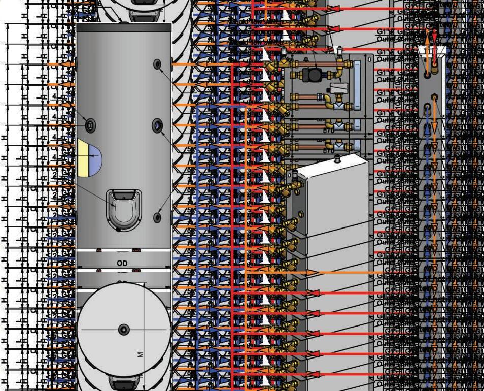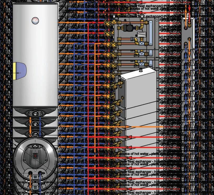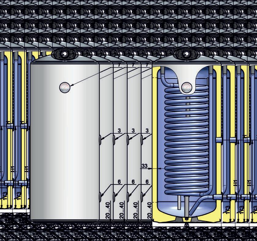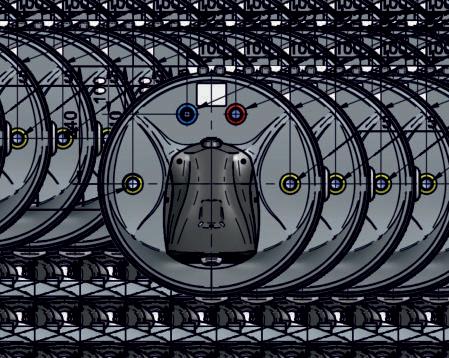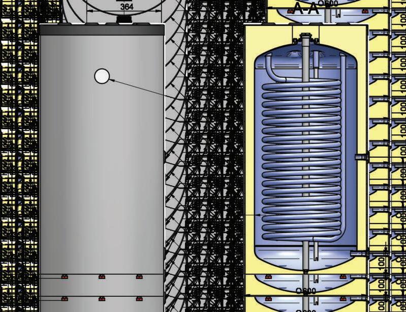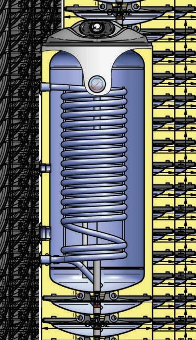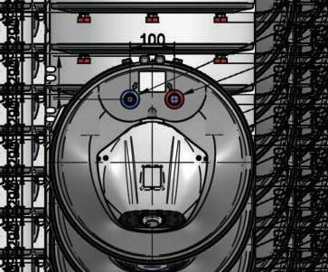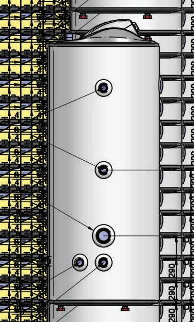




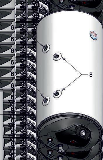


SOLAR WATER HEATERS FOR WALL MOUNTING WITH ONE HEAT EXCHANGER (S)
Parameters
Model
Volume group
Energy efciency class
Standing loss
Rated pre ss ure
Volume
Insulation thickness
W eight with packing
Heat exchanger (main heat)
Operating pressure
Maximum temperature of the heating uid
Maximum temperature in the tank heated by a heat exchanger
Surface area
Volume
Power according EN 12897
Heat-up time according EN 12897
Pressure drop
Maximum amount of drained water MIX 40°C according EN12897 when S1`s energy source is off
Electrical part (auxiliary heating)
Rated voltage
Rated electrical power
Heat-up time with electric heating element (up to 70°C) 3)
Maximum temperature in the tank when heated with electric heating element
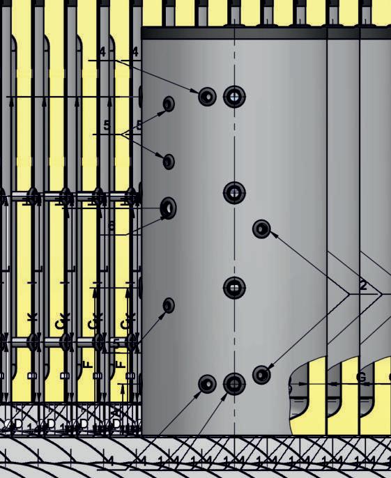
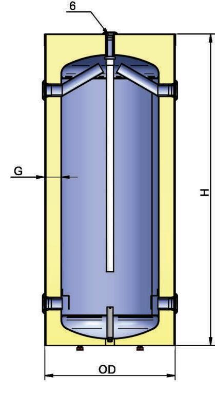
Connections
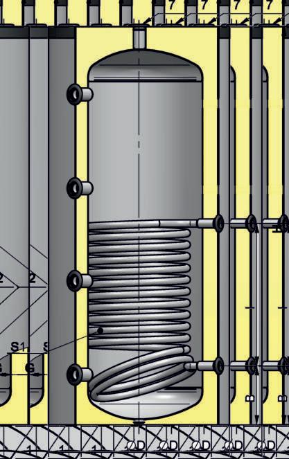
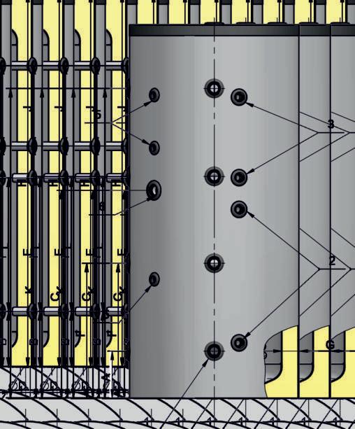
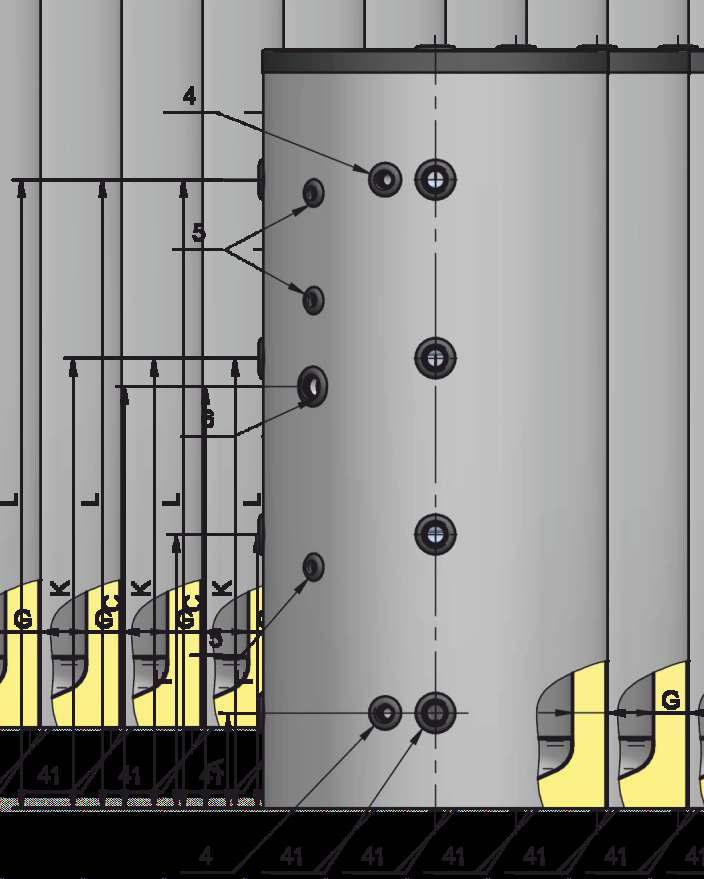
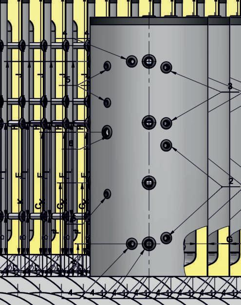
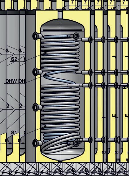
1: Hot water outlet
2: Cold water inlet - Drain
3: Temperature indicator
4: Control panel
5: Flange with a heating element
6: Heating coil - Feed

7: Heating coil - Return
8: Socket for thermostat
9: Illuminated switch
1. All values in the table are approximate.
2. The heat-up time with the electric resistance heater is for actual capacity.
7
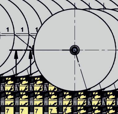
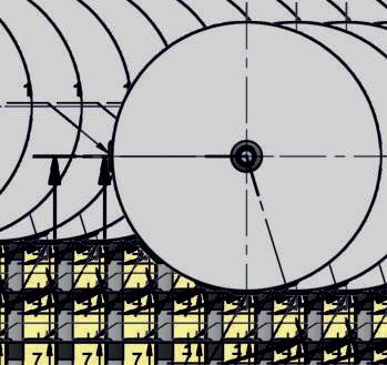
H H1 D W1 W H2 H3 H4 N W Mpa L mm kg Mpa °C °C m² L kW min mbar V~ kW min °C mm mm mm mm mm mm mm mm mm WV08039SL WV08039SR 80 B 44 0. 7 73 33 36.5 1 95 85 0.49 1.81 10 21 90 230 2/3 150/100 75 G1/2 M G1/2 M yes yes yes G1/2 F G1/2 F G1/2 F yes 1125 155 387 80 410 425 450255
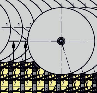
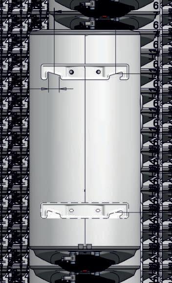
Dimensions
WV10046SL WV10046SR 100 B 47 0. 7 91 33 39 1 95 85 0.65 3.15 13.4 21 50 230 2/3 188/125 75 G1/2 M G1/2 M yes yes yes G3/4 F G3/4 F G1/2 F yes 1005 185 462 96 484 305 450255 WV12046SL WV12046SR 120 B 51 0. 7 112 33 44.5 1 95 85 0.65 3.15 12.2 28 50 230 2/3 232/155 75 G1/2 M G1/2 M yes yes yes G3/4 F G3/4 F G1/2 F yes 1170 185 462 96 484 470 450255 WV15046SL WV15046SR 150 B 54 0. 7 142 33 55 1 95 85 0.89 4.3 17.3 24.5 55 230 2/3 293/195 75 G1/2 M G1/2 M yes yes yes G3/4 F G3/4 F G1/2 F yes 1420 185 462 96 484 500 670 1003 240 72281S 200 B 59 0. 7 18 6 43 73 1 95 85 0.89 4.3 17.5 32 50 230 3 260 75 G1/2 M G1/2 M yes yes yes G3/4 F G3/4 F G1/2 F yes 1255 190 586 105 600 195 450 780 240 L116150190232310


Parameters
Model
Volume group
Energy efciency class
Standing loss
Rated pressure
Volume
Insulation thickness
Weight with packing
Heat exchanger (main heat)
Operating pressure
Maximum temperature of the heating uid
Maximum temperature in the tank heated by a heat exchanger
Surface area
Volume
Power according EN 12897
Heat-up time according EN 12897
Pressure drop
Maximum amount of drained water MIX 40°C according EN12897 when S1`s energy source is off
Electrical part (auxiliary heating)
Rated voltage
Rated electrical power
Heat-up time with electric heating element (up to 70°C) 3)
Maximum temperature in the tank when heated with electric heating element
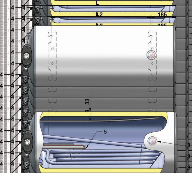
Connections
1: Hot water outlet
2: Cold water inlet - Drain
3: Temperature indicator

4: Control panel
5: Flange with a heating element
6: Heating coil - Feed
7: Heating coil - Return
8: Illuminated switch
1. All values in the table are approximate.
2. The heat-up time with the electric resistance heater is for actual capacity.
9
Dimensions L L2 W Mpa L mm kg Mpa °C °C m² L kW min mbar V~ kW min °C mm mm
WHM08046LSL WHM08046RSR 80 C 63 0. 7 76 33 32 1 95 85 0.35 1.71 7 30 80 230 2/3 157/105 75 G1/2 M G1/2 M yes yes yes G1/2 M G1/2 M yes 835 415 WHM10046LSL WHM10046RSR 100 C 67 0. 7 91 33 36.5 1 95 85 0.35 1.71 7.1 34 80 230 2/3 188/125 75 G1/2 M G1/2 M yes yes yes G1/2 M G1/2 M yes 1005 587 WHM12046LSL WHM12046RSR 120 C 71 0. 7 112 33 43 1 95 85 0.59 2.85 10 28 85 230 2/3 232/155 75 G1/2 M G1/2 M yes yes yes G1/2 M G1/2 M yes 1170 753 72280XBS 72280XBSR 150 C 77 0. 7 143 43 59 1 95 85 0.59 2.85 11.2 27.5 85 230 3 200 75 G1/2 M G1/2 M yes yes yes G1/2 M G1/2 M yes 1015 560 72281XBS 72281XBSR 200 C 84 0. 7 186 43 74 1 95 85 0.77 3.73 15 26.5 90 230 3 260 75 G1/2 M G1/2 M yes yes yes G1/2 M G1/2 M yes 1255 780 L 113130147170220



Parameters
Model
Volume group
Energy efciency class
Standing loss
Rated pressure Volume
Insulation thickness
Weight with packing
Heat exchanger (main heat)
Operating pressure
Maximum temperature of the heating uid
Maximum temperature in the tank heated by a heat exchanger
Heat exchanger S1
Surface area
Volume
Power according EN 12897
Heat-up time according EN 12897
Pressure drop
Maximum amount of drained water MIX 40°C according EN12897 when S1`s energy source is off
Heat exchanger S2
Surface area
Volume
Power according EN 12897
Heat-up time according EN 12897
Pressure drop
Maximum amount of drained water MIX 40°C according EN12897 when S2`s energy source is off
Electrical part (auxiliary heating)

Rated voltage
Rated electrical power
Heat-up time with electric heating element (up to 70°C) 3)
Maximum temperature in the tank when heated with electric heating element
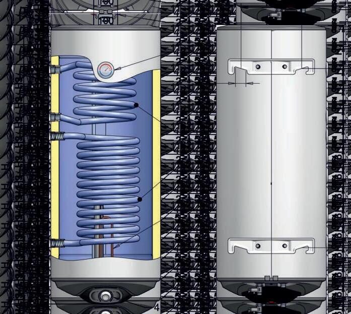
Connections
1: Hot water outlet
2: Cold water inlet - Drain 3: Temperature indicator
1. All values in the table are approximate.
2. The heat-up time with the electric resistance heater is for actual capacity.
11
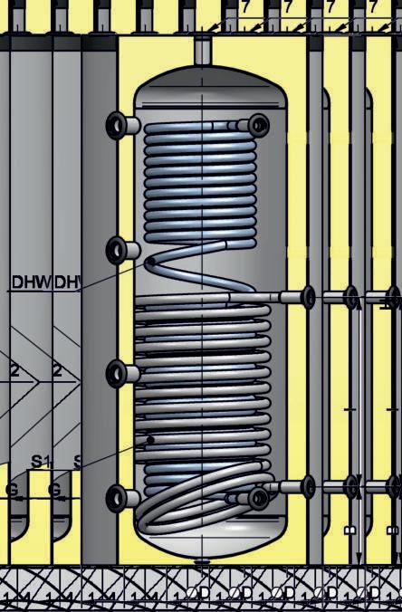
5:
6: Heat exchanger S2 - Feed 7: Heat exchanger S2 - Return 8: Heat exchanger S1 - Feed 9: Heat exchanger S1 - Return 10: Socket for thermostat 11: Illuminated switch Dimensions H H1 D W1 W H2 H3 H4 H5 H6 N ... W Mpa L mm kg Mpa °C °C m² L kW min mbar L m² L kW min mbar L V~ kW min °C mm mm mm mm mm mm mm mm mm mm mm WV12046S2L WV12046S2R 120 B 51 0.7 111 33 49.5 1 95 85 0.65 3.15 12.2 28 50 190 0.3 1.43 6.7 22 35 82 230 2/3 230/153 75 G1/2 M G 1/2 M yes yes yes G 3 / 4 F G 3 / 4 F G 3 / 4 F G 3 / 4 F G 1 / 2 F yes 1170 185 462 96 484 186 470 450 200 753 255 WV15046S2L WV15046S2R 150 B 54 0.7 140 33 59 1 95 85 0.89 4.3 17.3 24.5 55 232 0.3 1.43 6.7 22 35 82 230 2/3 290/193 75 G1/2 M G 1/2 M yes yes yes G 3 / 4 F G 3 / 4 F G 3 / 4 F G 3 / 4 F G 1 / 2 F yes 1420 185 462 96 484 218 500 670 200 1003 240
4: Control panel
Flange with a heating element


Parameters
Model
Volume group
Energy efciency class
Standing loss
Rated pressure Volume
Insulation thickness
Weight with packing
Heat exchanger (main heat)
Operating pressure
Maximum temperature of the heating uid
Maximum temperature in the tank heated by a heat exchanger
Heat exchanger S1
Surface area
Volume
Power according EN 12897
Heat-up time according EN 12897
Pressure drop
Maximum amount of drained water MIX 40°C according EN12897 when S1`s energy source is off
Heat exchanger S2
Surface area
Volume
Power according EN 12897
Heat-up time according EN 12897
Pressure drop
Maximum amount of drained water MIX 40°C according EN12897 when S2`s energy source is off
Electrical part (auxiliary heating)

Rated voltage
Rated electrical power
Heat-up time with electric heating element (up to 70°C) 3)
Maximum temperature in the tank when heated with electric heating element
1. All values in the table are approximate.
2. The heat-up time with the electric resistance heater is for actual capacity.
13
4:
5: Flange with
6: Heat exchanger S1 - Feed 7: Heat exchanger S1 - Return 8: Heat exchanger S2 - Feed 9: Heat exchanger S2 - Return 10: Socket for thermostat 11: Illuminated switch Dimensions H H1 D W1 W H2 H3 H4 H5 N ... W Mpa L mm kg Mpa °C °C m² L kW min mbar m² L kW min mbar V~ kW min °C mm mm mm mm mm mm mm mm mm mm WV10046S21L WV10046S21R 100 B 47 0.7 89 33 41.5 1 95 85 0.36 1.72 8.6 30 35 0.36 1.72 9.1 22 35 230 2/3 184/123 75 G 1 / 2 M G 1 / 2 M yes yes yes G 3 / 4 F G 3 / 4 F G 3 / 4 F G 3 / 4 F G 1 / 2 F yes 1005 185 462 96 484 187 300 450255 WV12046S21L WV12046S21R 120 B 51 0.7 111 33 51 1 95 85 0.53 2.58 12.7 27 40 0.53 2.58 13.4 21 40 230 2/3 230/153 75 G 1 / 2 M G 1 / 2 M yes yes yes G 3 / 4 F G 3 / 4 F G 3 / 4 F G 3 / 4 F G 1 / 2 F yes 1170 185 462 96 484 184 290 630 753 255 WV15046S21L WV15046S21R 150 B 54 0.7 140 33 58 1 95 85 0.53 2.58 12 33 40 0.53 2.58 12.5 27.5 40 230 2/3 290/193 75 G 1 / 2 M G 1 / 2 M yes yes yes G 3 / 4 F G 3 / 4 F G 3 / 4 F G 3 / 4 F G 1 / 2 F yes 1420 185 462 96 484 434 540 630 1003 240
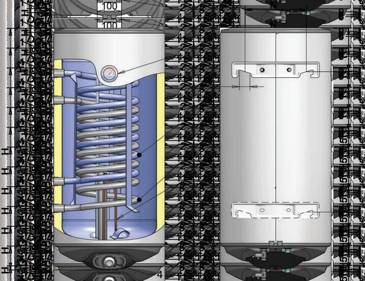
Connections 1: Hot water outlet 2: Cold water inlet - Drain 3: Temperature indicator
Control panel
a heating element
L L 143 111 183 149 219 190
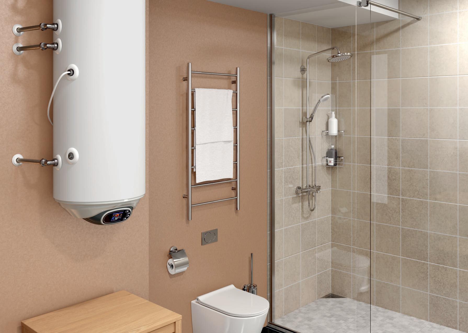
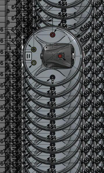
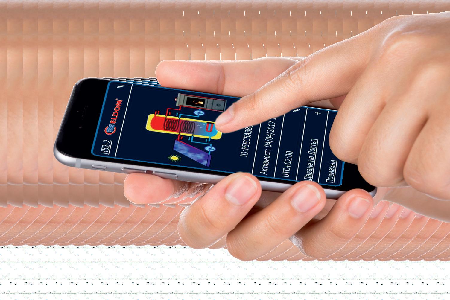
The online application myELDOM provides you teal-time information on the status of your water heating system. From your mobile device, you can remotely control all operating parameters of the combined ELDOM water heater.
The electronic control unit is distinguished by its modern and functional design and large color LCD display. This facilitates the process of adding new and useful functions for even more convenient use of the water heater and the entiresystemoperation.

1 4 On-Off / Back ▲/ set temp ▼/ menu Enter / Info Display

















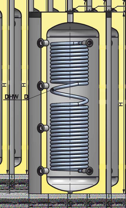
BIG CAPACITY COMBINED FLOOR STANDING WATER HEATERS UP 750 TO 2000L (S2)
Parameters
Model
Volume group
Energy efciency class
Standing loss
Rated pressure
Volume
Insulation thickness
Gross weight
Heat exchanger (main heat)
Operating pressure
Maximum temperature of the heating uid
Maximum temperature in the tank heated by a heat exchanger Appliance without / with auxiliary electric immersion heating element.
Heat exchanger S1
Surface area
Volume
NL (2)
Continuous output according DIN 4708
Flow rate according DIN 4708
Power according EN 12897
Heat-up time according EN 12897
Pressure drop
Maximum amount of drained water MIX 40°C according EN12897 when S1`s energy source is off
Heat exchanger S2
Surface area
Volume
NL (2)
Continuous output according DIN 4708
Flow rate according DIN 4708
Power according EN 12897
Heat-up time according EN 12897
Pressure drop
Maximum amount of drained water MIX 40°C according EN12897 when S2`s energy source is off
Electrical part (auxiliary heating)

Rated voltage
Rated electrical power
Heat-up time with electric heating element (up to 70°C) 3)
Maximum temperature in the tank when heated with electric heating element
7: Flange with a heating element
8: Socket for thermostat
27
°C
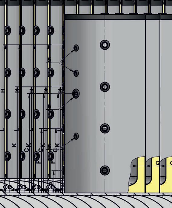
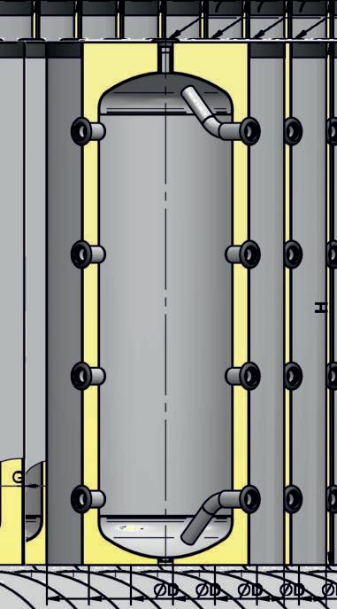
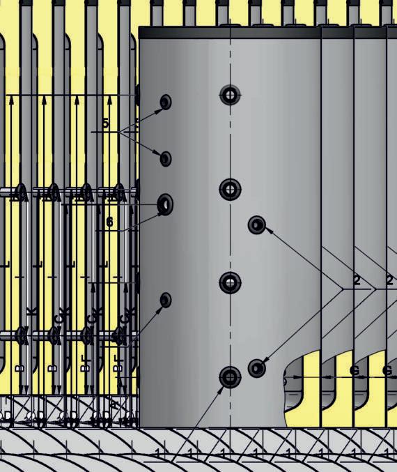
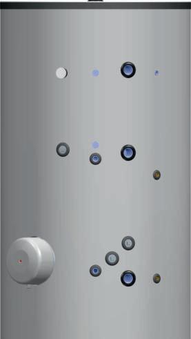
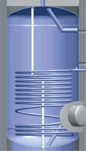
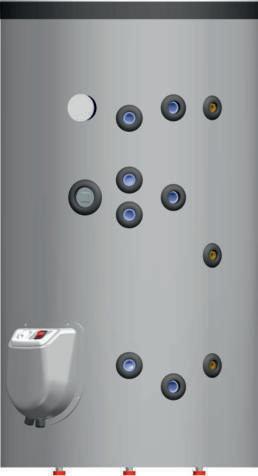
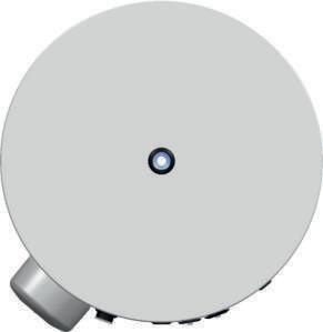
Connections 1: Thermometer 2: S2 - Feed 3: S2 - Return 4: Additional socket 5: S1 - Feed 6: S1 - Return
Dimensions A B C D E G H I J M P ... W Mpa L mm kg Mpa °C m² L kW L/min kW min mbar L m² L kW L/min kW min mbar L V kW min °C mm mm mm mm mm mm mm mm mm mm mm FV15013FS2 1500161 0.8 1455 100 408 1 110 3.04 20 35 91 38 31 117 70 1934 2.03 13.3 18 56 23 26 50 30 712 0/400 3N~ 0/9/12 ---/540/405 75 Yes G 1 F G 1 F G 1 1 / 2 F G 1 F G 1 F Yes G1/2 F G 2 F G 2 F G 2 F G 1 1 / 2 F G 2 F 395 445 1215 1250 1265 100 2210 730 470 1385 1755 95/85 FV20014FS2 2000186 0.8 1978 100 515 1 110 4.25 27.9 45 130 54 41 111 80 2515 2.73 18 20 76 31 33 60 50 1085 0/400 3N~ 0/9/12 ---/730/550 75 Yes G 1 F G 1 F G 1 1 / 2 F G 1 F G 1 F Yes G1/2 F G 2 F G 2 F G 2 F G 1 1 / 2 F G 2 F 415 465 1255 1400 1285 100 2255 730 470 1535 1775 95/85 FV75010FS2 750127 0.6 721 80 243 1 110 2.03 13.3 19 65 27 26.2 76.6 50 1058 1.22 8 5 35 14 19.7 49.5 20 519 0/400 3N~ 0/9/12 ---/280/210 75 Yes G 1 F G 1 F G 1 1 / 2 F G 1 F G 1 F Yes G1/2 F G 1 1/2 F G 3 / 4 F G 1 1/2 FG 1 1 / 4 F 330 420 950 1010 990 80 1655 470 290 1110 1280 95/85 FV10010FS2 1000137 0.6 920 80 278 1 110 3.04 20 30 94 39 34 77 70 1390 2.03 13.3 16 57 23 28 42 40 650 0/400 3N~ 0/9/12 ---/368/277 75 Yes G 1 F G 1 F G 1 1 / 2 F G 1 F G 1 F Yes G1/2 F G 1 1/2 F G 3 / 4 F G 1 1/2 FG 1 1 / 4 F 330 420 1110 1010 1150 80 2000 630 470 1110 1620 95/85
9: Fresh water inlet - Drain 10: Recirculation 11: Hot water outlet 12: Additional socket 13: Hot water outlet
S2 - water heater with two heat exchangers C - rated power of the heating elements 12kW.



MONOVALENT WATER HEATERS FOR HEAT PUMP SYSTEMS (D1)
Parameters
Model
Volume group

Energy efciency class
Standing loss
Rated pressure
Volume
Insulation thickness
Gross weight
Heat exchanger (main heat)
Operating pressure
Maximum temperature of the heating uid
Maximum temperature in the tank heated by a heat exchanger Appliance without / with auxiliary electric immersion heating element.
Surface area
Volume
NL (2)
Continuous output according DIN 4708
Flow rate according DIN 4708
Power according EN 12897
Heat-up time according EN 12897
Pressure drop
Maximum amount of drained water MIX 40°C according EN12897 when S1`s energy source is off
Electrical part (auxiliary heating)
Rated voltage
Rated electrical power
Heat-up time with electric heating element (up to 70°C) 3)
Maximum temperature in the tank when heated with electric heating element
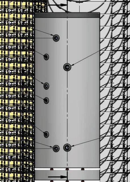
31
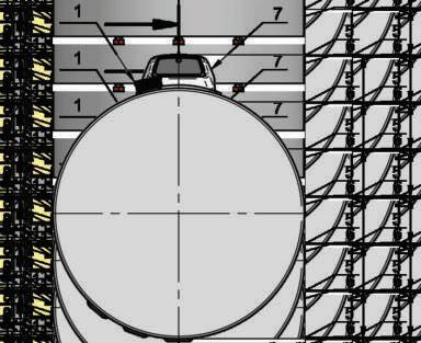
Connections 1: Thermometer 5: S1 - Feed 6: S1 - Return 7: Flange with a heating element 8: Socket for thermostat 9: Fresh water inlet - Drain 10: Recirculation 11: Hot water outlet Dimensions A B D G H I M P ... W Mpa L mm kg Mpa °C m² L kW L/min kW min mbar L V kW min °C mm mm mm mm mm mm mm mm FV 50080D1 500 B 71 0. 8 441 80 192 1 110 5.06 33.2 25 135 55 65 20 65 675 0/230~ /400 3N~ 0/3/9 ---/570/190 75 Yes G1 1/4 F G1 1/4 F Yes G1/2 F G 1 F G 3/4 F G 1 F 230 240 800 80 1765 890 890 1455 FV 30067D1 300 B 50 0. 8 249 85 121 1 110 3.11 15 13 81 33 47 16.5 45 401 0/230~ /400 3N~ 0/3/9 ---/320/107 75 Yes G1 F G1 F Yes G1/2 F G 3/4 F G 3/4 F G 3/4 F 190 200 670 85 1605 830 760 1330 FV 20067D1 200 B 48 0. 8 182 85 89 1 110 2.07 10 7 59 24 36 16.5 40 305 0/ 230 ~ 0/ 3 ---/ 230 75 Yes G1 F G1 F Yes G1/2 F G 3/4 F G 3/4 F G 3/4 F 190 200 670 85 1215 560 760 950 °C 95/8595/8595/85


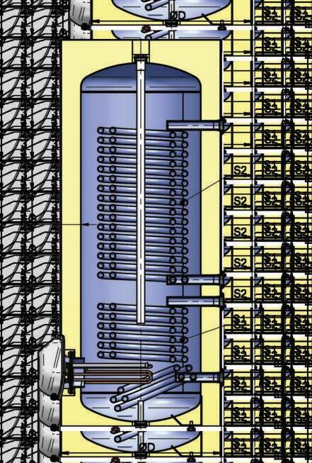
BIVALENT WATER HEATERS FOR LOW-TEMPERATURE SYSTEMS (D2)
Parameters
Model
Volume group
Energy efciency class
Standing loss
Rated pressure
Volume
Insulation thickness
Gross weight
Heat exchanger (main heat)
Operating pressure
Maximum temperature of the heating uid
Maximum temperature in the tank heated by a heat exchanger Appliance without / with auxiliary electric immersion heating element.
Heat exchanger S1
Surface area
Volume
NL (2)
Continuous output according DIN 4708
Flow rate according DIN 4708
Power according EN 12897
Heat-up time according EN 12897
Pressure drop
Maximum amount of drained water MIX 40°C according En12897 when S1`s energy source is off
Heat exchanger S2
Surface area
Volume
NL (2)
Continuous output according DIN 4708
Flow rate according DIN 4708
Power according EN 12897
Heat-up time according EN 12897
Pressure drop
Maximum amount of drained water MIX 40°C according En12897 when S2`s energy source is off
Electrical part (auxiliary heating)

Rated voltage
Rated electrical power
Heat-up time with electric heating element (up to 70°C) 3)
Maximum temperature in the tank when heated with electric heating element
33
Connections 1: Thermometer 2: S2 - Feed 3: S2 - Return 4: Additional socket 5: S1 - Feed 6: S1 - Return 7: Flange with a heating element 8: Socket for thermostat
Fresh water inlet - Drain 10: Recirculation 11: Hot water outlet Dimensions A B C D E G H I J M P W Mpa L mm kg Mpa °C m² L kW L/min kW min mbar m² L kW L/min kW min mbar V kW min °C mm mm mm mm mm mm mm mm mm mm mm FV20067D2 200 B 49 0.8 180 85 100 1 110 0.75 3.6 4 22 9 13 45 30 1.63 7.9 7 42 17 27 9 15 0/ 23 0~ 0/ 3 ---/ 230 75 Yes G 1 F G 1 F G 1 1 / 2 F G 1 F G 1 F Yes G 1 / 2 F G 3 / 4 F G 3 / 4 F G 3 / 4 F 190 200 445 670 490 85 1215 200 440 760 950 FV30067D2 300 B 52 0.8 246 85 129 1 110 1.19 5.7 8 35 14 21 40 35 2.37 11.5 12 65 27 30.6 16.9 15 0/230~ /400 3N~ 0/3/9 ---/320/107 75 Yes G 1 F G 1 F G 1 1 / 2 F G 1 F G 1 F Yes G 1 / 2 F G 3 / 4 F G 3 / 4 F G 3 / 4 F 190 200 560 670 605 85 1605 315 640 760 1330 FV50080D2 500 B 76 0.8 435 80 206 1 110 2.03 13.3 18 60 24 24.7 57 35 3.8 25 25 81 33 39.3 22.3 55 0/230~ /400 3N~ 0/3/9 ---/570/190 75 Yes G1 1/4 F G1 1/4 F G 1 1 / 2 F G1 1/4 F G1 1/4 F Yes G 1 / 2 F G 1 F G 3 / 4 F G 1 F 230 240 645 800 700 80 1765 350 675 890 1455 °C L L 95/8595/8595/85 301424736 135261450
9:
