Service Training Meeting Guide 682SESV1682 March 1997 TECHNICAL PRESENTATION 793C OFF-HIGHWAY TRUCK Cat 793c Manual Servicio Full download: http://manualplace.com/download/cat-793c-manual-servicio/ This is the cut pages sample. Download all 232 page(s) at: ManualPlace.com
793C OFF-HIGHWAY TRUCK MEETING GUIDE 682 SLIDES AND SCRIPT
AUDIENCE
Level II - Service personnel who understand the principles of machine systems operation, diagnostic equipment, and procedures for testing and adjusting.
CONTENT
This presentation provides basic maintenance information and describes the systems operation of the engine, power train, steering, hoist and the air system and brakes for the 793C Off-highway Truck. The Automatic Retarder Control (ARC) and the Traction Control System (TCS) are also discussed.
OBJECTIVES
After learning the information in this meeting guide, the serviceman will be able to:
1. locate and identify the major components in the engine, power train, steering, hoist and the air system and brakes; 2. explain the operation of the major components in the systems; and 3. trace the flow of oil or air through the systems.
REFERENCES
793C Off-highway Truck Service Manual SENR1440
793C Off-highway Truck Parts Book SEBP2503
Vital Information Management System (VIMS) Service Manual SENR6059
Fluid Power Graphic Symbols User's Guide SENR3981
PREREQUISITES
Interactive Video Course "Fundamentals of Mobile Hydraulics" TEVR9001
Interactive Video Course "Fundamentals of Electrical Systems" TEVR9002
STMG 546 "Graphic Fluid Power Symbols" SESV1546
Estimated Time: 8 Hours
Visuals: 184 (2 X 2) Slides
Serviceman Handouts: 4 Data Sheets Form: SESV1682
Caterpillar Inc. Date: 3/97
©
1997
SUPPLEMENTAL MATERIAL
Specification Sheets
793B Off-highway Truck AEHQ5061
793C Off-highway Truck AEHQ5186
Salesgrams
Vital Information Management System (VIMS) TELQ4478
793B Rear Axle Improvements TELQ3736
785B/789B/793B Introduction TELQ3725 789B/793B Feature Status TELQ4477
Video Tapes
793C Off-highway Truck--Service Introduction SEVN4016
793C Marketing Introduction AEVN3742
3500 EUI Service Introduction SEVN2241 Intelligence of Powerful Connections AEVN2974
Suspension Cylinder Charging TEVN2155
TPMS Management/Technical Information AEVN2211
TPMS Operating Tips AEVN2212
Automatic Electronic Traction Aid (AETA) Introduction SEVN9187
Service Training Meeting Guides
STMG 625 "793 Off-highway Truck" SESV1625
STMG 660 "785B/789B/793B Off-highway Trucks--Maintenance" SESV1660
STMG 681 "3500B Engine Controls--Electronic Unit Injection (EUI)" SESV1681
Technical Instruction Modules
Vital Information Management System--785B/789B/793B Off-highway Trucks SEGV2610
Vital Information Management System--Introduction SEGV2597
3500 Electronic Engine Controls--Introduction SEGV2588
3500 Electronic Engine Controls--Off-highway Trucks SEGV2589
Electronic Programmable Transmission Control (EPTC II) SEGV2584
769C - 793B Off-highway Trucks--Torque Converter and Transmission Hydraulic Systems SEGV2591
785B/789B/793B Off-highway Trucks--Steering System SEGV2587
769C - 793B Off-highway Trucks--Hoist System SEGV2594
769C - 793B Off-highway Trucks--Air System and Brakes SEGV2595
Automatic Retarder Control System SEGV2593
Automatic Electronic Traction Aid SEGV2585
769C - 793B Off-highway Trucks--Suspension System SEGV2599
- 3 - STMG 682 3/97
SUPPLEMENTAL MATERIAL (Continued)
Booklets
Know Your Cooling System SEBD0518
Diesel Fuels and Your Engine SEBD0717 Oil and Your Engine SEBD0640
Special Instructions
Using the ECAP NEXG4521 Machine Functions Service Program Module SEHS9343
Using the 8T8697 Electronic Control Analyzer Programmer (ECAP) SEHS8742
Using the 7X1700 Communication Adapter Group SEHS9264
Use of 6V3000 Sure-Seal Repair Kit SMHS7531
Use of CE Connector Tools SEHS9065
Servicing DT Connectors SEHS9615
Use of 8T5200 Signal Generator/Counter Group SEHS8579
Repair of 4T8719 Bladder Accumulator Group SEHS8757
Suspension Cylinder Servicing SEHS9411
Using 1U5000 Auxiliary Power Unit (APU) SEHS8715 Using the 1U5525 Attachment Group SEHS8880
Brochures
Caterpillar Vital Information Management System (VIMS) AEDK2946
Caterpillar Electronic Technician NEHP5614
Caterpillar DataView NEHP5622
Diesel Engine Oil (CG4) Product Data Sheet PEHP5026 How to Take a Good Oil Sample PEHP6001 Air Filter Service Indicator PEHP9013
Intelligence of Powerful Connections AEDK2966
Caterpillar Fully Automatic Transmission AEDQ0066
Caterpillar Oil-cooled Multiple Disc Brakes AEDK2546
Caterpillar Automatic Retarder Control AEDK0075
Miscellaneous
Electronic Diagnostic Code Pocket Card
NEEG2500
Pressure Conversion Chart SEES5677
793B Transmission Assembly Wall Chart SENR6834
793B Final Drive Assembly Wall Chart SENR8602
Improved Transmission/Drive Train Oil (IRM) PELE0179
- 4 - STMG 682 3/97
- 5 - STMG 682 3/97 TABLE OF CONTENTS INTRODUCTION ........................................................................................................................7 WALK AROUND INSPECTION ...............................................................................................11 OPERATOR'S STATION ............................................................................................................36 ENGINE ......................................................................................................................................49 Cooling System .....................................................................................................................66 Lubrication System 77 Fuel System 80 Air Induction and Exhaust System .......................................................................................85 POWER TRAIN .........................................................................................................................90 Power Train Components......................................................................................................91 Power Train Hydraulic System ...........................................................................................103 Electronic Programmable Transmission Control (EPTC II) 120 STEERING SYSTEM 128 HOIST SYSTEM 157 AIR SYSTEM AND BRAKES 177 Operator Controls................................................................................................................179 Air Charging System ...........................................................................................................182 Parking and Secondary Brake System ................................................................................188 Service and Retarder Brake System 195 AUTOMATIC RETARDER CONTROL (ARC) 206 TRACTION CONTROL SYSTEM (TCS) 211 CONCLUSION 221 SLIDE LIST ..............................................................................................................................222 SERVICEMAN'S HANDOUTS ...............................................................................................224
INSTRUCTOR NOTES
- 6 - STMG 682 3/97
793C OFF-HIGHWAY TRUCK
INTRODUCTION
This presentation provides an introduction to the Caterpillar 793C Off-highway Truck. Included in this package is a walk around inspection which provides information about daily service requirements and identifies the locations of the major components. The major systems of the truck will also be discussed. The major systems include the engine, power train, steering, hoist, and the air system and brakes.
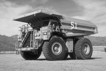
The 793C is the largest rigid frame truck produced by Caterpillar. The 793C is equipped with a Caterpillar 3516B engine rated at 1716 kW (2300 gross hp) and 1616 kW (2166 flywheel hp). The load carrying capacity is 218 Metric tons (240 tons) at a Gross Machine Weight (GMW) of 376488 kg (830000 lbs.).
This slide shows a view of the left side of the truck. Notice that the body canopy is extended over the cab to protect the front of the truck from falling objects.
The fuel tank is located on the left side of the truck. •
- 7 -
STMG 682 3/97
• 3516B DITA engine
1
C 1997 Caterpillar Inc.
Fuel tank
• Extended body canopy
2
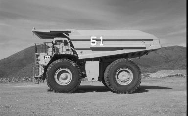
• Main system air tank:
- Air starting
- Service/retarder brakes
• Main hydraulic tank:
- Hoist system
- Brake system
• Torque converter case used as sump for converter and transmission
Shown is the right side of the truck. The large air tank on the right platform supplies air for starting the truck and for the service and retarder brake system.
The main hydraulic tank is also visible. The hydraulic tank supplies oil for the hoist system and the brake system.
On the 793B truck, torque converter oil is also supplied from the main hydraulic tank. A transmission oil supply tank is located in front of the main hydraulic tank.
The 793C now uses the torque converter case as the supply tank for the torque converter and the transmission.
- 8 -
STMG 682 3/97
3
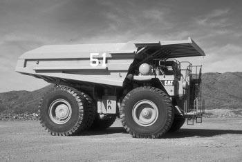
• 789B and 793C are similar
The 793C is similar in appearance to the 789B and may be difficult to recognize from a distance. The 793C can be recognized by the four air filters and the diagonal access ladder. The 789B has only two air filters mounted in the same locations and is equipped with two vertical ladders.
- 9 -
• 793C has four air filters STMG 682 3/97
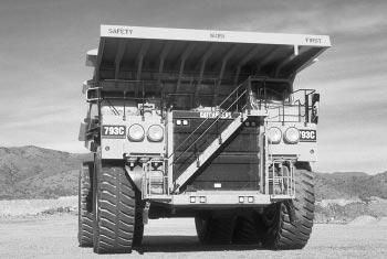
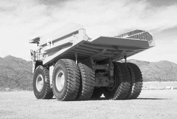
• Rear suspension cylinders
4
The truck body has a dual-slope main floor and a "vee" bottom to center the load and reduce spills. The steel used to construct the body has a yield strength of 6205 bar (90000 psi).
The rear suspension cylinders absorb bending and twisting stresses rather than transmitting them to the main frame.
- 10 -
• Truck body STMG 682 3/97
793C MAINTENANCE
793C Service Procedure
WALK AROUND INSPECTION
WALK AROUND INSPECTION
• Read the Operation and Maintenance Manual
Before working on or operating the truck, read the Operation and Maintenance Manual (Form SEBU6995) thoroughly for information on safety, maintenance and operating techniques.
Safety precautions and Warnings are provided in the manual and on the truck. Be sure to identify and understand all symbols before starting the truck.
The first step to perform when approaching the truck is to make a thorough walk around inspection. Look around and under the truck for loose or missing bolts, trash build-up and for coolant, fuel or oil leaks. Look for indications of cracks. Pay close attention to high stress areas as shown in the Operation and Maintenance Manual.
- 11 - STMG 682 3/97
5
• Front wheel bearing inspection plug (arrow)
• Tire inflation
6
The front wheel bearing oil level is checked and filled by removing the plug (arrow) in the center of the wheel bearing cover. The oil should be level with the bottom of the plug hole.
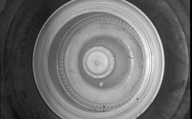
Check the tire inflation pressure. Operating the truck with the wrong tire inflation pressure can cause heat build-up in the tire and accelerate tire wear
NOTE: Care must be taken to ensure that fluids are contained while performing any inspection, maintenance, testing, adjusting and repair of the machine. Be prepared to collect the fluid in suitable containers before opening any compartment or disassembling any component containing fluids. Refer to the "Tools and Shop Products Guide" (Form NENG2500) for tools and supplies suitable to collect and contain fluids in Caterpillar machines. Dispose of fluids according to local regulations and mandates.
- 12 -
STMG 682 3/97
1. Front wheel bearing axle housing breather
2. Suspension cylinder grease outlet fittings
• Make sure grease flows from outlet fittings
7
Inspect the condition of the front wheel bearing axle housing breather (1). The breather prevents pressure from building up in the axle housing. Pressure in the axle housing may cause brake cooling oil to leak through the Duo-Cone seals in the wheel brake assemblies.
Two grease outlet fittings (2) are located on the front of each suspension cylinder. The grease supply line for the Auto Lubrication System is located at the rear of the suspension cylinder. No grease outlet fittings should be located on the same side of the suspension cylinder as the grease fill location. Having an outlet fitting on the same side of the suspension cylinder as the grease fill location will prevent proper lubrication of the cylinder
Make sure that grease is flowing from the outlet fittings to verify that the suspension cylinders are being lubricated and that the pressure in the cylinders is not excessive.

- 13 -
STMG 682 3/97
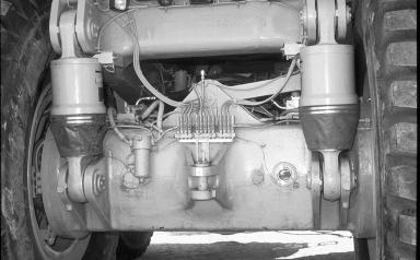
1 2
Located behind the right front tire are the rear brake oil coolers (1), the parking brake release filter (2), and the torque converter charging filter (3).
One of the three injector banks (4) for the automatic lubrication system is also in this location. These injectors are adjustable and regulate the quantity of grease that is injected during each cycle (approximately once per hour).
A solenoid air valve provides a controlled air supply for the automatic lubrication system. The solenoid air valve is controlled by the Vital Information Management System (VIMS), which energizes the solenoid ten minutes after the machine is started. The VIMS energizes the solenoid for 75 seconds before it is de-energized. Every 60 minutes thereafter, the VIMS energizes the solenoid for 75 seconds until the machine is stopped (shut down). These settings are adjustable through the VIMS keypad in the cab.
INSTRUCTOR NOTE: For more detailed information on servicing the automatic lubrication system, refer to the Service Manual Module "Automatic Lubrication System" (Form SENR4724).
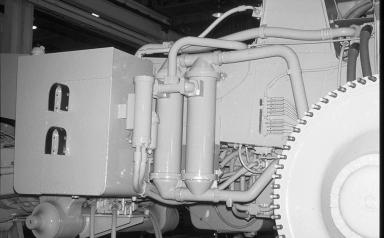
- 141. Rear
coolers 2. Parking
3. Torque
charging
4. Automatic
8 STMG 682 3/97 4 2 1 3
brake oil
brake release filter
converter
filter
lubrication injector bank
9
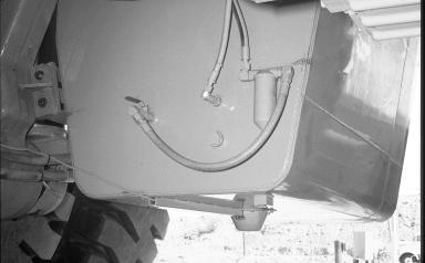
• Hoist and brake hydraulic tank
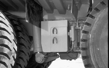
Shown is the hoist and brake hydraulic tank and the oil level sight gauges (arrows). The oil level is normally checked with the upper sight gauge. The oil level should first be checked with cold oil and the engine stopped. The level should again be checked with warm oil and the engine running.
The lower sight gauge can be used to fill the hydraulic tank when the hoist cylinders are in the RAISED position. When the hoist cylinders are lowered, the hydraulic oil level will increase. After the hoist cylinders are lowered, check the hydraulic tank oil level with the upper sight gauge as explained above.
- 15 -
• Oil level sight gauges (arrows) STMG 682 3/97
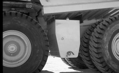
• Final drives
• Flush all axle components after a failure
10
The rear axles are equipped with double reduction planetary final drives. The magnetic plug (arrow) should be removed from the final drives at regular intervals and checked for metal particles. For some conditions, checking the magnetic plug is the only way to identify a problem which may exist.
The rear axle is a common sump for the differential and both final drives. If a final drive or the differential fails, the other final drive components must also be checked for contamination and then flushed. Failure to completely flush the rear axle after a failure can cause a repeat failure within a short time.
NOTICE
The rear axle is a common sump for the differential and both final drives. If a final drive or the differential fails, the other final drive components must also be checked for contamination and then flushed. Failure to completely flush the rear axle after a failure can cause a repeat failure within a short time.
- 16 -
• Check magnetic plugs (arrow) for metal STMG 682 3/97
The differential oil level is checked by viewing the oil level sight glass (1). The oil should be level with the bottom of the inspection hole.
Two oil level sensors (2) provide input signals to the VIMS which informs the operator of the rear axle oil level.
A rear axle oil filter (3) is used to remove contaminants from the rear axle housing.
Check the charge condition of the rear suspension cylinders when the truck is empty and on level ground.
The second of three injector banks (4) for the automatic lubrication system is mounted on the top rear of the differential housing.
Above the lubrication injectors is a breather (5) for the rear axle. Inspect the condition of the breather at regular intervals. The breather prevents pressure from building up in the axle housing. Excessive pressure in the axle housing can cause brake cooling oil to leak through the Duo-Cone seals in the wheel brake assemblies.
INSTRUCTOR NOTE: For more detailed information on servicing the suspension system, refer to the Special Instruction "Suspension Cylinder Servicing" (Form SEHS9411).
- 17 -
11 STMG 682 3/97 2 2 4 1 5 3
1. Differential oil level sight glass
2. Rear axle oil level sensors 3. Rear axle housing oil filter • Rear suspension cylinders 4. Automatic lubrication injector bank 5. Rear axle breather
12
• Cable holds body up
The cable that holds the body up is stored below the rear of the body Whenever work is to be performed while the body is raised, the safety cable must be connected between the body and the rear hitch to hold the body in the raised position.

WARNING
The space between the body and the frame becomes a zero clearance area when the body is lowered. Failure to install the cable can result in injury or death to personnel working in this area.
- 18 -
STMG 682 3/97
• Fuel level sight gauge (arrow)
13
The fuel tank is located on the left side of the truck. The fuel level sight gauge (arrow) is used to check the fuel level during the walk around inspection.
- 19 -
• Fuel tank STMG 682 3/97
2 3 1
14
2. Condensation drain valve
Open the drain valve (2) to remove condensation from the fuel tank.
A fuel level sensor (3) is also located on the fuel tank. The fuel level sensor provides input signals to the VIMS which informs the operator of the fuel level.
This is the cut pages sample. Download all 232 page(s) at: ManualPlace.com
- 20 -
1. Primary fuel filter STMG 682 3/97
The primary fuel filter (1) is located on the inner surface of the fuel tank.
3. Fuel level sensor Cat 793c Manual Servicio Full download: http://manualplace.com/download/cat-793c-manual-servicio/
