APRIL 2021
VOLUME 33
ISSUE 1
A publication of Engineering Design & Testing Corp.
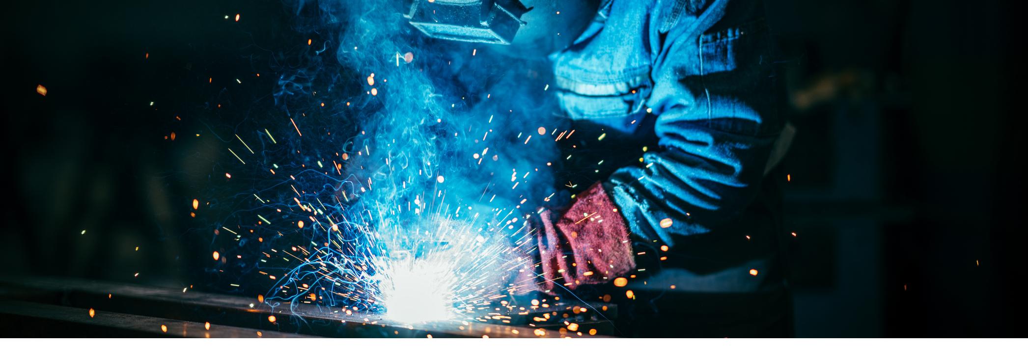
WELDING PROCESS
Processes that are used to weld metals
FREEZE PROTECTION OF HVAC COILS
How to protect an HVAC unit from freezing which could ultimately result in water damage
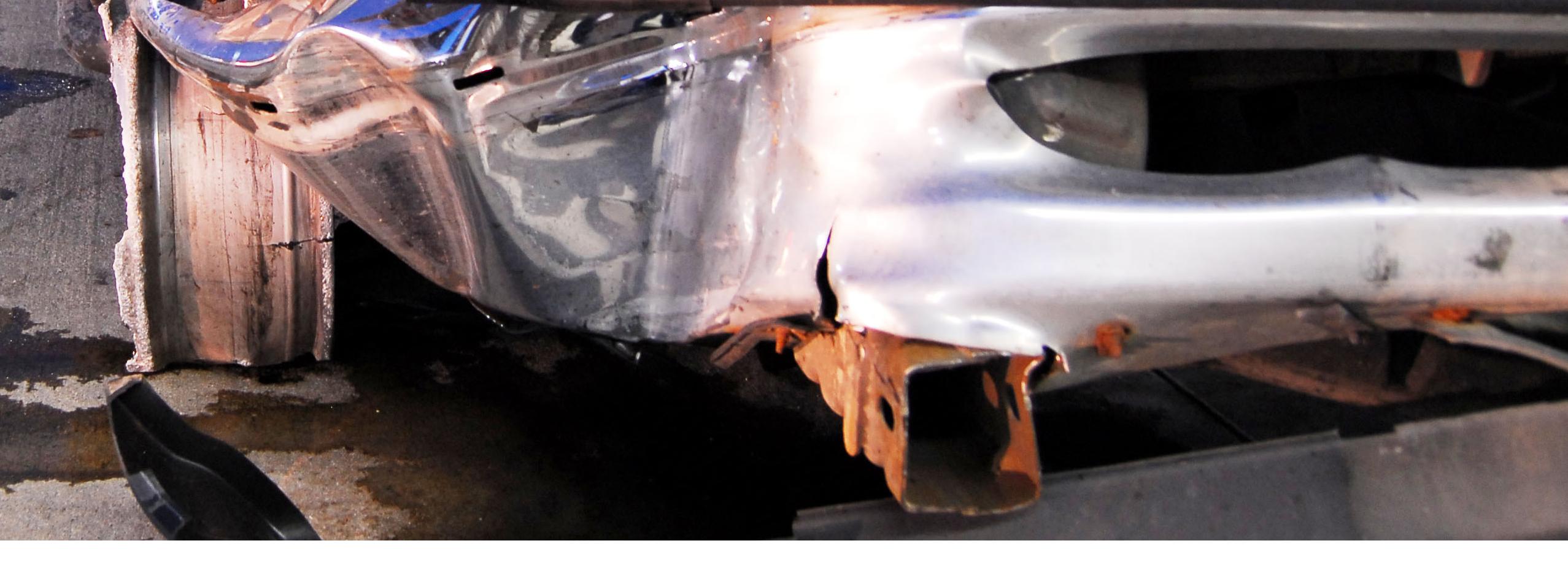
WHEEL SEPARATION A left-rear wheel separated from a bucket truck while being driven on an interstate highway. The driver lost control and rolled the truck as a result.
www.edtengineers.com
Engineering Design & Testing Corp. is an association of forensic engineers dedicated to the study, and interpretation of loss.
A Message from the Chief Engineer
Dear Friends, As I write this note it has been over a year since the COVID-19 lockdown was initiated, subjecting all of us to personal, professional and financial burdens during the course of 2020. However, with the decline of cases toward the end of last year and mass vaccinations, 2021 is looking promising and I am optimistic that life will be somewhat back to “normal” in a few months. Although we here in New England are in the midst of spring, the lingering effects of Old Man Winter remain as the Firm continues to receive investigations of freeze-up claims that took place a couple of months ago. Our neighbors to the south, who enjoy warmer climates, are not immune from the periodic “polar vortexes” that are sent down from the Arctic as we saw with the devastation experienced by Texas in February. HVAC systems are especially vulnerable to extreme ambient conditions that often result in extensive water damage to large commercial buildings. Tom Dombrowski provides insight as to the various reasons, some obvious and some not so obvious, for HVAC coil freezing, especially in locations where low ambient temperatures are expected. In addition to HVAC systems, the mechanical engineers at the Firm have a wide range of expertise beyond mechanical systems. Although welding is a common means of joining metal items that we use every day such as cars and bridges, many people are not aware of how the welding process works or the different means used to weld metals. Jim Middleton provides an introduction into the welding process and the various techniques used to weld metals. Many times, our mechanical engineers are required to sort out equipment malfunctions that are alleged to be due to some prior repair effort, or a cause that appears to be obvious. To quote Mark Twain, "Truth is stranger than fiction, but it is because fiction is obliged to stick to possibilities; truth isn’t". As Wayne Maltry explains, there was plenty of “fiction” involving “possibilities” in a truck rollover case that he investigated. The truth, which was stranger than the possibilities, required physical observations, calculations and metallurgical data to get to the real reason that the accident took place.
Regards,
Thomas D. Traubert, P.E.
Chief Engineer, Vice President, and District Engineering Manager
2 | The Stress Point TM | www.edtengineers.com
APRIL 2021
THE STRESS POINT TM is published twice a year by Engineering Design & Testing Corp. for our clients and friends.
April 2021 Volume 33, Issue 1
Those wishing to obtain an EDT Portfolio of Technical Services and THE STRESS POINT TM should contact Danielle Newbanks at (803) 796-6975 or marketing@edtengineers.com.
FEATURED
For reprint permission, please contact the editor.
6-10 WHEEL SEPARATION 8-11 The Magic of Ferries
Corporate Contacts Director of Business Development Charles "Chuck" Jackson (803) 796-6975 cjackson@edtengineers.com
A left-rear wheel separated from a bucket truck while being driven on an interstate highway. The driver lost control and rolled the truck as a result.
From here to there, for a fare. On the Cover: Truck post accident
Creative Content Specialist / Editor / Design and Layout Danielle Newbanks (803) 796-6975 dnewbanks@edtengineers.com Post Office Box 8027 Columbia, South Carolina 29202 (800) 338-5227
@
Visit Us Online
www.edtengineers.com
Follow us on LinkedIn Facebook Twitter
IN THIS ISSUE 2
A MESSAGE FROM THE CHIEF ENGINEER
Thomas D. Traubert, P.E.
4-5
WELDING PROCESS
James I. Middleton Jr., M.E., P.E.
6-10 WHEEL SEPARATION
G. Wayne Maltry, AMT, BSAE, M.S.M.E., P.E.
11-13 FREEZE PROTECTION OF HVAC COILS
Thomas W. Dombrowski, P.E., CFEI
© 2021 Engineering Design & Testing Corp., All rights reserved.
APRIL 2021
www.edtengineers.com | The Stress Point TM | 3
WELDING PROCESS
By: James I. Middleton Jr., M.E., P.E.
Material joining is an integral part of our engineered society. As it is usually not possible to create machines as a single piece, the materials these machines are made of must be joined. When it comes to metals, a common method of joining is welding. Welding falls into two separate categories, fusion and diffusion. Fusion welds involve the joining of materials using sufficient heat to melt portions of either of the materials to be joined. In many cases, as the portions are melted, filler materials are added to assist in the formation of the joint. When choosing a filler metal, consideration must be given as to the compatibility of this filler to the base metals being welded. In addition, various methods of shielding the metals from the surrounding air while they are in the liquid state are used. My hope with this article is that the reader will have an appreciation of the varied types of joining that fall into the classification known as welding. Diffusion welding or solid state welding represents the original methods of welding. The first and oldest of the many welding methods is highlighted every week in one of my favorite TV shows, Forged in Fire. It is known as forge welding. Forge welding originated around 1800 BC in Turkey. This method of joining involves heating pieces of metal to high temperature (below its melting temperature) and then hammering the pieces together. This causes the metals to diffuse together and eliminates air pockets forming billets that can then be wrought into many different shapes. The remaining welding methods I will discuss are all fusion welding methods. That is, as stated previously, the remaining methods I will discuss involve the melting of a small portion of the metals being joined. Typically, these fusion methods involve arc welding. With arc welding, while the metal is in the liquid state, it is imperative to shield it from the atmosphere to reduce the amount of oxidation it experiences. Therefore, to understand each of the different welding techniques, it is
important to discuss how these welding methods shield the liquid metals. The first arc welding process doesn’t use shielding as it requires the pieces to be in complete contact with both the welder and each other. As such, the physical contact provides for the shielding. This technique, known as spot welding, passes a current through the clamped components. This current melts the metal in the clamp and causes it to fuse. Spot welds are widely used in the automotive industry for the assembly of body panels as they can easily be fitted to robots and their use automated. The first, and most generally known arc welding technique, is Shielded Metal Arc Welding (SMAW). SMAW welding is commonly referred to as “Stick Welding.” SMAW utilizes a power supply to create a high voltage that can create an arc. Early models of this power supply which are still in production were known as “buzz boxes” because of the distinct sound their transformers produced. My first experience with welders as a young child involved field repairs made to farm equipment on my grandfather’s farm using a buzz box. SMAW utilizes electrodes that contain a filler metal core and a flux material on the outside of the rod. When in use, the welder causes an arc to form between the electrode and the base metal. This process is called “striking the arc.” After forming the arc, the welder moves the electrode between the metals to be joined to create the molten weld puddle while maintaining the distance between the end of the electrode. This task of maintaining the arc is complicated by the fact that the electrode becoming shorter as the filler metal and flux are also melting. The flux assists in pulling impurities out of the melted metals in addition to forming a slag and gases which shield the liquid weld pool while it freezes back into a solid. As a result of this slag formation, welders must chip it away between welding passes. Multiple weld passes are required in the assembly of
4 | The Stress Point TM | www.edtengineers.com
APRIL 2021
larger components when the joints are large no matter the weld technique utilized. Gas Metal Arc Welding (GMAW) is probably the most widely used arc welding method. Commonly referred to as MIG (Metal Inert Gas) welding, it is most widely used as it has a fast production rate and is easily automated. MIG welders use a controller device known as a gun. This gun activates the welding machine. The welding machine consists of a power supply to create the high voltage necessary to facilitate arcing, a coil feeding machine that meters the feed rate of wire used as a filler material in the weld, and valving and metering for application of an inert or semi-inert shielding gas. When the welder presses the trigger on the gun, the machine energizes the filler wire and starts the flow of the shielding gas. Typically, as the wire feeds, it will automatically strike the arc decreasing the workload on the welder. However, if the feed rate is too high, the wire may short into the metals and break the arc. As such, the welding machine does require some adjustment when changing type or thickness of material to be welded. The filler wire and shielding gas used in the welder vary based upon the metal to be welded. Typically, the shielding gas is argon which is a unreactive inert gas, carbon dioxide, which has a very low reactivity at it is very stable, or a combination of the two. As with the shielding slag in stick welding, the purpose of the shielding gas is to prevent oxidation in the molten weld pool. The final arc welding process typically used is commonly known as TIG (Tungsten Inert Gas). TIG welding, formally known as Gas Tungsten Arc Welding (GTAW) is by far the slowest but at the same time the most precise of the arc welding processes. The process still requires a generator which develops a constant current but has a variable voltage. Like the GMAW process, an inert gas is used as a shielding gas. The gas also serves to help conduct heat from the electrode to the workpiece. The electrode used in GTAW is Tungsten or a Tungsten alloy. The electrode is mounted in a torch that held by the welder. The torch also has an orifice that allows for the shielding gas to flood the weld zone. Filler rods are held in the welder’s free hand. As the welder’s hands are both occupied with the welding torch and filler rod, control of the generator is usually utilizing a foot pedal. The foot pedal allows for the precise arc control required for the TIG process. In some applications, a TIG pass is first conducted to precisely join two components together. Additional passes are then made using a MIG process to fill in the remainder of the joint. This allows for the precise manufacture of assemblies such as process piping. Laser beams, oxyfuel (oxyacetylene being the foremost example), and induction heating are additional sources of heat energy used in fusion welding. The overall process of heating the materials to melting remains the same. Many more welding processes exist that have specific APRIL 2021
applications. For example, railroad rails are joined using an exothermic reaction of thermite. This produces extreme heat in a very localized area. This results in melting of the rail ends and the filler material fusing into a homogenous mass that then cools back into a solid. In addition to forge welding described earlier, additional solidstate welding techniques have become popular as precise manufacturing techniques. For example, NASA is using a technique known as friction stir welding in the manufacture of the tank structure of the new Space Launch System (SLS) rocket. Friction stir welding involves placing the two components to be joined into contact and then using a nonconsumable tool to heat the contact surface to softening using heat generated by friction. As a result, high weld strengths with fewer weld defects are produced. An additional solid-state technique that is worth noting, if for nothing else than its notoriety, is explosion welding. Explosion welding uses the extreme pressures contained within an explosion to fuse metals together. Welds are used to join materials together. As the technology grows, many materials in addition to metals, for example plastics, are now being joined using welding techniques. Typically in these applications, solid-state methods pervade.
ABOUT THE AUTHOR JAMES I. MIDDLETON JR., M.E., P.E. Columbia District Office | Columbia, South Carolina Mr. Middleton is a consulting mechanical, automotive, and materials / metallurgical engineer in Columbia, South Carolina. Mr. Middleton joined EDT in 1995. His areas of expertise at the firm involve engineering analyses including metallurgical analysis, loading analysis involving manual calculations as well as Finite Element Analysis (FEA) techniques, as well as failure and fracture analysis of varying types of mechanical components and systems. In addition, Mr. Middleton also is the senior vehicle engineer within the firm. In this role he analyzes issues involving passenger and commercial vehicles, heavy trucking, as well as off-road and construction equipment. This work includes accident reconstruction in addition to mechanical evaluations. STATE LICENSES: Mr. Middleton is a registered professional engineer in Alabama, California, Florida, Georgia, Missouri, North Carolina, South Carolina, Tennessee, Texas, Virginia and West Virginia. www.edtengineers.com | The Stress Point TM | 5
WHEEL SEPARATION By: G. Wayne Maltry, AMT, BSAE, MSME, P.E.
O
ccasionally, an analysis is dismissed on the assumption that it is too academic, insinuating that it would not be useful in a “real world” situation. In forensic science, that assumption may not hold true, especially when several socalled academic observations point to the same conclusion.
Inspection of the bucket truck revealed that it did, in fact, exhibit indications of having been rolled (Figures 1 and 2). In addition, all of the wheel studs on the incident wheel hub had snapped off. (Figure 3). The fractured wheel stud surfaces,
A left-rear wheel separated from a bucket truck while being driven on an interstate highway. The driver lost control and rolled the truck as a result (truck wreck). A passenger in the bucket truck was injured in the incident. It was asserted that a truck repair company who last worked on the truck was responsible because they had not properly retightened (under torqued) the wheel nuts after servicing the brakes. Although this assertion seemed reasonable on the surface, there were several inconsistent issues that were immediately evident.
Figure 3: Driver side rear wheel hub shown with wheel studs snapped off
Figure 1: Work Truck, passenger side front.
Figure 4: Left side oxidized wheel stud fracture surface
although weathered, still exhibited a flat granular appearance and included circumferential ratchet marks consistent with a reversed bending, fatigue fracture mode. (Figure 4). It was known, however, that fractured wheel studs are not typical to left side wheel separations. Left side wheel separations usually occur after the wheel nuts spin off and right side wheel separations tend to occur after the wheel studs break off. 1
Figure 2: Work Truck, driver side rear
1
Bailey and Bertoch, "Mechanisms of Wheel Separations," SAE, 2009.
6 | The Stress Point TM | www.edtengineers.com
APRIL 2021
In simplistic terms, the left side loosening effect is attributed to the counterclockwise direction of wheel rotation which, coincidentally, is the same direction threaded fasteners are turned to loosen them. Fractured wheel studs on the left rear wheel, therefore, was not consistent with the condition of under-torqued wheel nuts.
Figure 5: Paint mark indicating overheated brake pads
A second observation while inspecting the bucket truck was excessive oxidation of the rear wheel hubs. While most often a result of general surface corrosion due to long-term exposure to ambient moisture, excessive oxidation to steel components can also result from excessive heating. This excessive oxidation condition, at first made off-hand, later became more significant when a paint mark was identified consistent with the spacing between the parking brake pads (Figure 5).
This paint mark width indicated that the bucket truck’s wheel hubs, which at one time had been painted, had also been stopped with overheated parking brake pads, an indication of parking brake misuse. This observation prompted removal of the wheel hub for a first-hand inspection of the parking brake pads. It was determined that the parking brake pads were worn smooth with less than 4 mm of the original 12 mm pad thickness remaining (Figures 6 and 7). This worn parking brake pad condition was inconsistent with having had new brake pads applied to the bucket truck and also inconsistent with typical use of parking brakes wherein the pads are applied against a stationary wheel hub in order to keep the bucket truck still. The wheel hub and brakes, therefore, were removed from the bucket truck and secured for laboratory examination. It was reported that the bucket truck had been driven for nearly a month, from SC, where the brake work was performed, to TX, where it remained onsite for several weeks, and then had covered most of the ground on its way to NC before the truck wreck took place. The distance traveled since the repair was determined to be 2,971 miles. In addition, 225/70R19.5 size tires had been in service. These tires have an overall diameter, minus 5% load deflection, of 30.3 inches, or 2.5 feet, which translates to 7.9 feet in circumference. In other words, for each revolution of the tire, and load cycle on the wheel stud, the bucket truck would travel 7.9 feet. These figures (2,971 miles and 7.9 feet per wheel revolution) correspond to nearly two million load cycles on the wheel studs. Had the wheel studs been left loose when the brakes were serviced, one bending load (flex) would have resulted on each wheel stud every time the wheel rotated. Repeated flexing results in metal fatigue, and just like when you bend a paper clip back and forth until it breaks, flexing metal wheel studs will also break, or fracture. But the fracture will only take place if the flexing exceeds certain load and cycle limits.
Figure 6: Parking brake pads with worn-smooth surfaces
The cycle limit is 106, or one million, rotations. In other words, if the load is such that the wheel stud sustains one million rotations, then the wheel stud is not likely to fatigue and fracture if additional wheel rotations are experienced. It bears repeating that the wheel studs in this incident fractured at two million load cycles. This observation indicated an event took place between the time that the brakes were serviced and the rollover incident. No maintenance related to wheel removal was reported subsequent to the brake service work. It was, therefore, theorized that parking brake misuse culminated in the wheel separation incident.
Figure 7: Parking brake pad thickness, less than 4 mm of the original 12 mm remains
APRIL 2021
To either prove or refute this parking brake misuse theory, a couple of questions were asked:
www.edtengineers.com | The Stress Point TM | 7
1. How much heat would it take to cause the wheel nuts to loosen? 2. Is there any evidence that the wheel hub experienced this level of heating? Question 1 was answered through additional measurements and calculations. It was known that wheel nuts maintain secure attachment of the wheel assembly to the wheel hub by providing clamping force. In other words, wheel nuts sufficiently tight on wheel studs clamp the wheel to the wheel hub. This clamping force is provided by tightening the wheel nuts just enough to stretch the wheel studs but not so much as to induce permanent deformation. This level of tightening is referred to as preload. Because metal studs become longer when they are heated, the preload on a wheel stud can be reduced if the wheel studs become overheated after they have been tightened.
of elasticity for this wheel stud material, a 140 ft. lb. applied torque force and stretch of 20,039 lbs. and 0.0066 inches, respectively, were calculated. The calculations, therefore, revealed that the wheel stud strain (stretch) would be just short of 0.007 inch when the specified torque of 140 ft. lbs. (preload) is applied to the wheel nuts. That stretch value applied to the thermal expansion equation for steel corresponds to a temperature of just 616°F for the 20,039 lb. of wheel stud preload to be completely diminished (no-preload temperature). So if the wheel hub becomes heat soaked such that the wheel studs reach a temperature of 616 °F, the wheel studs lose all preload and, as a result, begin to flex and can become unthreaded from the wheel studs while the bucket truck was being driven. However, the bending only takes place while the wheel studs are heat soaked. Once temperatures return to ambient, bending ceases and eventual fracture is not likely to take place. To answer the question whether there was any evidence that the wheel studs reached this temperature, a metallurgical analysis of the incident wheel stud material was performed. The metallurgical analysis included the following activities: 1. Clean and photograph wheel stud fracture surfaces 2. Section fractured and exemplar wheel studs
Figure 8: Fractured wheel stud extraction from sectioned wheel hub
3. Hardness test fractured and exemplar wheel studs 4. Chemically test fractured and exemplar wheel stud materials 5. Metallurgically mount fractured and exemplar wheel stud materials 6. Use optical and metallographic microscopy to examine fractured and exemplar wheel stud materials
Figure 9: Exemplar wheel stud
The wheel studs were removed from the hub by cutting the wheel hub flange, thereby saving the fracture surface from mechanical damage (Figure 8). Once removed, the wheel studs were determined to be 10.9 Class (alloy steel quenched and tempered), size M14 x 1.5 pitch, flat head, ribbed-necked studs. The fractured wheel stud’s original thread length of 1.85 inches was determined by researching and procurement of the required replacement part from an authorized parts supplier (Figure 9). Using the published values of major diameter, pitch diameter, thread pitch, tensile stress area, stud length and modulus
The wheel stud fracture surfaces, once a majority of surface oxidation had been removed, exhibited a clearer view of its circumferential ratchet marks and, in addition, provided a view of residual beach marks (Figure 10). Once again, these features
Figure 10: Left side cleaned wheel stud fracture surface
8 | The Stress Point TM | www.edtengineers.com
APRIL 2021
were consistent with a reversed bending fatigue fracture mode. Hardness Testing is used to determine whether the structure, and therefore the strength of the material has changed. A lower hardness corresponds to a weakened and more ductile, or softer, material. The hardness of the incident wheel studs were, therefore, compared to that of the exemplar wheel stud material. Hardness for fastener material is measured by Rockwell C-scale units. Two incident studs, Nos. 2 and 6, and the one exemplar stud were tested in both macrohardness, with a 1 KG load, and microhardness, with a 500 gram OD to core load. An average 5 percent macrohardness decrease, and an average 1.4 percent microhardness decrease for the incident wheel studs was identified. At this point it was argued that although the hardness decreased in both cases, the decrease was within the limits of process variations and not significant enough to indicate excessive heat exposure. To answer this argument, the chemistry and microstructure of the samples must first be examined. Chemical testing of the wheel stud material revealed and average 0.35 percent carbon content alloy steel with principal alloying elements of Manganese (Mn), Silicon (Si) and Molybdenum (Mo). Certain combinations of alloying elements effect changes in the structure and behavior of the material, especially how it responds to applied loads. The chemical analysis was consistent with ISO898-1 2013 E CL. 10.9 material. This is an international standard that defines the properties of fasteners made of carbon and alloy steel. There were no significant differences between the chemical content of the incident and exemplar wheel stud materials.
Figure 12: Micro 4, Incident Wheel Stud 2, Core
As expected all the samples exhibited a tempered martensite microstructure. The martensitic structure forms when medium carbon steels are put through a hardening process. Martensite is identified as a matrix of randomly oriented light and dark strips, or laths. The darker laths, which contain a substance called cementite, have higher carbon content than do the lighter laths. When compared, the incident wheel stud microstructure had a more varied, or mottled appearance, which is typical of the initial stages of a process called spheroidization. Spheroidization takes place when the material is subjected to heat sufficient to start softening the material. An evenly distributed network of particulate spheres could also be identified in the incident samples that were absent in the exemplar samples. These spheres, which are characteristic of carbide precipitants, are accentuated with red circles in Figure 13.
The samples were mounted in plastic so they could be polished and examined under a metallographic microscope. This process is necessary to view how the different phases of a material are structured. Like the hardness, the different microstructures result in different mechanical properties wherein strength, wear resistance and endurance properties can vary. The exemplar and incident wheel stud microstructures are shown in Figures 11 and 12. Figure 13: Same as Figure 12 but with spherical particulates accentuated
William Smith, in Structure and Properties of Engineering Alloys, 2nd edition, 1993 indicates that cementite in carbon and alloy steels will spheroidize and form carbides at temperatures between 752 to 1,112°F (Smith, Page 60). As shown in the above calculations, this spheroidization temperature is well hot enough to exceed the no-preload temperature of 616°F calculated above.
Figure 11: Micro 1, Exemplar Wheel Stud, Core
APRIL 2021
Moreover, a 0.35% Carbon steel will not experience a significant decrease in hardness unless its initial hardness is in the range of
www.edtengineers.com | The Stress Point TM | 9
50-60 HRC. If the 0.35% C steel’s initial hardness is 35 HRC, it will decrease to 32 HRC at 900°F and 28 HRC at 1000°F. This 900°F is well within the range that cementite in the tempered martensite structure will spheroidize (Smith, Page 73).
CONCLUSIONS: 1. The wheel hub had become heat soaked such that the wheel studs attained a temperature between 752 and 1,112°F. 2. The wheel stud temperature was sufficient to exceed the calculated 616°F temperature at which the left side wheel nut would experience a complete loss of wheel nut preload.
3. The complete loss of preload resulted in wheel nut loosening, a reversed bending fatigue load, and eventual fracture of the left side, rear wheel studs. 4. Given the oxidized condition of the wheel hub, and the brake pad wear that is not typical for parking brakes the wheel hub became heated due to parking brake misuse, wherein the parking brake remained applied while the bucket truck traveled an extended distance. 5. Given the fatigue life calculation, based on the distance traveled and the manner in which the bucket truck was used since brake servicing was completed, the parking brake had been misused well after the brakes were serviced.
ABOUT THE AUTHOR G. WAYNE MALTRY, AMT, BSAE, MSME, P.E. Columbia District Office | Columbia, South Carolina Mr. Maltry is an Aerospace, Mechanical, and Automotive consulting engineer in Columbia, South Carolina. Mr. Maltry joined EDT in 2007. He offers consulting services in the following areas: fracture and failure analysis, including finite element analysis; aircraft crash and vehicle collision investigation and reconstruction; origin and cause of air and land vehicle, structure and equipment fires; machinery scope of damages; assessment of appliances, machinery, vehicles and equipment (including HVAC); evaluation and analysis of process equipment, plumbing and piping; industrial accident analysis; and lightning damage assessment. STATE LICENSES: Mr. Maltry is a registered professional engineer in Alabama, Florida, Georgia, Mississippi, North Carolina, Pennsylvania, South Carolina, Tennessee, Texas and Virginia.
10 | The Stress Point TM | www.edtengineers.com
APRIL 2021
FREEZE PROTECTION OF HVAC COILS By: Thomas W. Dombrowski, P.E., CFEI
Many HVAC air-handling units contain heating and cooling coils that contain steam or water. Since most air-handling units introduce outdoor air into the building, these coils that will be exposed to this outdoor air must be protected from conditions in which water within a coil will freeze. Figure 1 shows typical ruptures of copper HVAC coil tubes as the result of water within the coil freezing.
the outdoor air damper should be in a full-closed position and vice-versa. However, there are at least three scenarios that can cause part or all of the heating coil to be exposed to freezing conditions. 1. The improper mixing of the return and outdoor air in the mixing box causes stratification of the air as its passes across the heating and cooling coils. Stratification is the layering of the two air streams. Using Figure 2 as an example, improper mixing of the return and outdoor air in the mixing box could produce a warmer layer (return air) at the top of the air-handling unit and a colder layer (outdoor air) at the bottom of the airhandling unit.2. A stuck open outdoor air damper as the result of a malfunction of the damper or actuator. Or the outdoor air damper may be locked in an “open” position by maintenance. 3. A malfunction of the air-handling unit controls.
Figure 1
A typical mixed air temperature senor as part of the air-handling unit controls system will not recognize stratification because it reports an average temperature as measured across the airhandling unit (thus averaging the cold and warm sections of airflow). Therefore, to protect the heating coil a low temperature control (or freezestat) is placed on the discharge side of the heating coil. A freezestat has a vapor-charged sensing element (or capillary) that is intended to open an electrical circuit upon sensing a drop in temperature. The function of a freezestat is to protect coils from exposure to freezing air temperatures if the air at the discharge of the heating coil falls below a predetermined setpoint by:
Figure 2
Figure 2 shows a schematic of a typical air-handling unit. When outdoor air conditions are right, the return air and outdoor air dampers modulate in unison to maintain the desired supply air temperature (typically, in the winter months this would be 55 to 65 °F). When the return air damper is in a full-open position APRIL 2021
1. Shutting down the air-handling unit supply fan. 2. Closing the outdoor air dampers. 3. Opening the heating coil control valve. This will protect the heating coil if an outdoor air damper is stuck open. www.edtengineers.com | The Stress Point TM | 11
The freezestat contains a manual reset button that needs to be pressed in order for the air-handling unit to resume operating. Note: Some freezestats have an automatic reset when the temperature rises above the setpoint plus a differential.
But even freezestats aren’t fool proof. I have run across three different scenarios where the freezestat had failed to protect the heating coil. Sometimes conditions will cause the freezestat to shut down air-handling unit numerous times and building maintenance staff tire of resetting the freezestat.
Figure 3
Figure 3 shows a typical freezestat body, the freezestat has an adjustable range that can be adjusted in order to trigger at a desired temperature (typically set at about 38 °F).
Figure 5
Figure 5 shows an example where building maintenance staff had set the freezestat to trip at 15°F. This may have worked if the heating system had contained an adequate water-glycol mix. Also, instead of “hardwiring” the freezestat to shut-down the air-handling unit sometimes control system providers will wire to freezestat to the air-handling unit controller and use software to shut-down the air-handling unit. However, this allows the end-user (building owner) to override the freezestat so that it never shuts down the air-handling unit.
Figure 4
Figure 4 shows the proper installation of the freezestat capillary sensor as mounted across the face of the heating coil. The typical length of the capillary tube is 20 feet and if any 1-foot section of the capillary senses a temperature below the desired temperature setting of the freezestat will cause the main freezestat electrical contacts to open. The freezestat may also be equipped with a second set of alarm contacts that close upon sensing a low temperature condition. This alarm contact is used to generate an alarm in a building automation system. The capillary sensor is mounted across the coil in a manner in which every square foot of the coil is covered by a portion of the capillary sensor. When installed in this manner the freezestat will sense if one portion of the coil has been exposed to freezing temperatures as the result of stratification. Multiple freezestats can be mounted in order to accommodate coils larger than 20 square feet in area.
Figure 6
A third and most common problem is the improper installation of the freezestat capillary. Figure 6 shows the installation of two freezestat capillary sensors within an air-handling unit.
12 | The Stress Point TM | www.edtengineers.com
APRIL 2021
Figure 7 shows a schematic drawing of the layout of two freezestat capillary sensors. It is clear that the two freezestat capillary sensors were mounted in a manner in which most of the coil was not protected by the capillary sensors. Also, mounting the freezestat downstream from the blower fan will create a situation where any stratification in the mixing box will not be detected since the supply fan will mix the return and outdoor air streams. In closing, the proper installation of a freezestat is required in order to protect HVAC water coils from freezing.
Figure 7
ABOUT THE AUTHOR THOMAS W. DOMBROWSKI, P.E., CFEI New England District Office | Hartford, Connecticut Mr. Dombrowski is a Mechanical consulting engineer in Hartford, Connecticut. Since joining EDT in April 2007, he has provided consulting services in the area of root cause analysis of malfunctions of HVAC and plumbing systems and their associated control systems in residential, commercial and industrial applications. He also provides consulting services in the analysis of matters involving machinery and mechanical systems. Prior to joining the firm, Mr. Dombrowski worked with a leading worldwide supplier of building control systems, specializing in the design, programming, installation and commissioning of building management systems specifically, HVAC controls. He also has experience in the design, equipment selection and installation of air and hydronic HVAC systems. This experience includes a variety of installations, including educational, government, healthcare, hospitality, life sciences, museum and retail facilities. STATE LICENSES: Mr. Dombrowski is a licensed engineer in the following states: Connecticut, Florida, Maine, Massachusetts, New Hampshire, New York State, Pennsylvania, Rhode Island and Vermont.
APRIL 2021
www.edtengineers.com | The Stress Point TM | 13
Post Office Box 8027 Columbia, South Carolina 29202-8027
Visit Us Online
www.edtengineers.com
A publication of Engineering Design & Testing Corp. April 2021 | Volume 33, Issue 1
EDT OFFICE LOCATIONS: Corporate Office 1022 State Street, Cayce, SC 29033 (803) 796-6975
Engineers Licensed in every State
Across the United States
Birmingham District Office 2748 Alton Rd. Suite 100 Birmingham, AL 35210 (205) 838-1040
Kansas City District Office 8405 Melrose Drive Lenexa, KS 66214 (913) 859-9580
Columbia District Office 1105 State Street Cayce, SC 29033 (803) 791-8800
Mid-Atlantic District Office 7905 Browning Rd. Suite 114 Pennsauken, NJ 08109 (856) 662-0070
Charleston District Office 1668 Old Trolley Rd. Suite 200A Summerville, SC 29485 (843) 832-1052
Nashville District Office 130 Seaboard Lane Franklin, TN 37067 (615) 915-5255
Charlotte District Office* 5009 West W.T. Harris Blvd. Suite A (Northridge Business Center) Charlotte, NC 28269 (704) 523-2520
New England District Office 425-C Hayden Station Rd. Windsor, CT 06095 (860) 285-8000
Cleveland District Office 925 Engle Rd. Suite C Middleburg Heights, OH 44130 (440) 239-0362 Dallas-Fort Worth District Office 990 N. Bowser Rd. Suite 740 Richardson, TX 75081 (972) 437-6200
Decades of Quality Service
Houston District Office 13805 West Road #300 Houston, TX 77041 (281) 463-4548
Oakland District Office 2221 Commerce Ave. Suite A Concord, CA 94520 (925) 674-8010 Orlando District Office 750 S. North Lake Blvd. Suite 1020 Altamonte Springs, FL 32701 (407) 865-9900 Seattle-Tacoma District Office 2006 48th Avenue Ct. Suite E Building 11, Fife, WA 98424 (253) 345-5187 South Florida Post Office Box 590487 Fort Lauderdale, Florida 33359 (954) 743-4500
*Services in North Carolina and New York provided by the affiliated firm EDT.Engineers, P.C.