5 minute read
FREEZE PROTECTION OF HVAC COILS


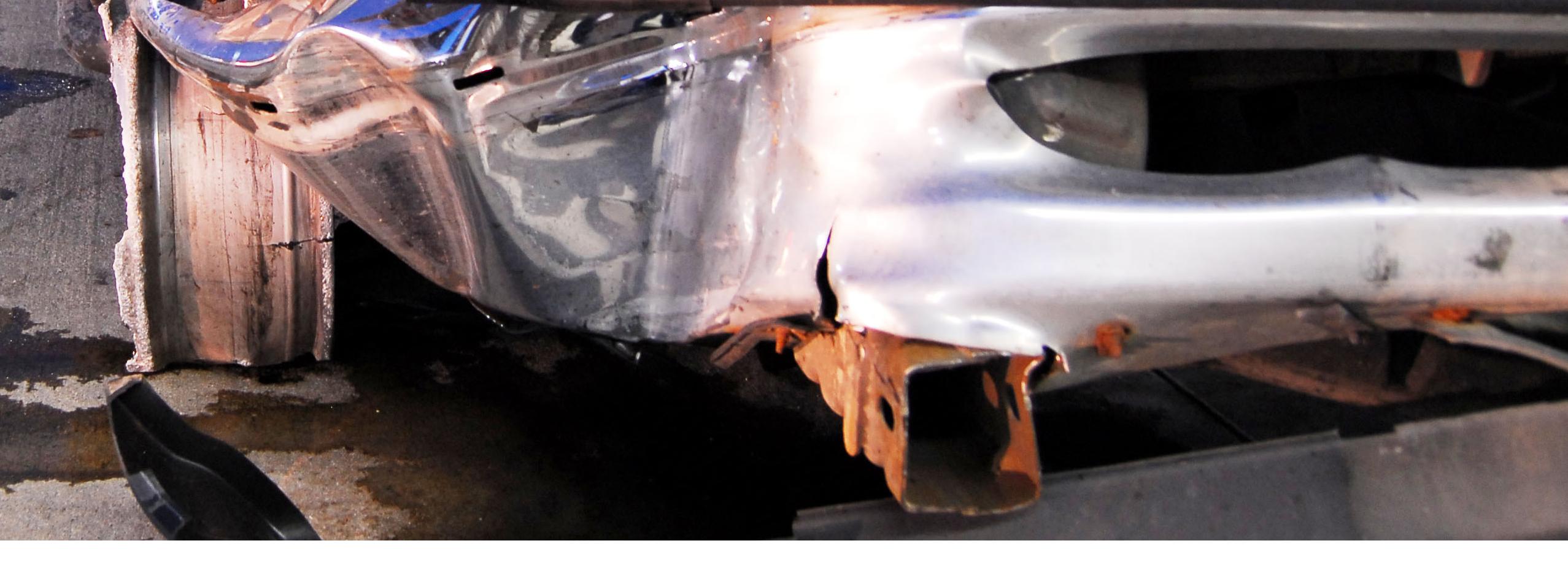
Many HVAC air-handling units contain heating and cooling coils that contain steam or water. Since most air-handling units introduce outdoor air into the building, these coils that will be exposed to this outdoor air must be protected from conditions in which water within a coil will freeze. Figure 1 shows typical ruptures of copper HVAC coil tubes as the result of water within the coil freezing.

Advertisement
Figure 1

Figure 2
Figure 2 shows a schematic of a typical air-handling unit. When outdoor air conditions are right, the return air and outdoor air dampers modulate in unison to maintain the desired supply air temperature (typically, in the winter months this would be 55 to 65 °F). When the return air damper is in a full-open position
the outdoor air damper should be in a full-closed position and vice-versa. However, there are at least three scenarios that can cause part or all of the heating coil to be exposed to freezing conditions.
1. The improper mixing of the return and outdoor air in the mixing box causes stratification of the air as its passes across the heating and cooling coils. Stratification is the layering of the two air streams. Using Figure 2 as an example, improper mixing of the return and outdoor air in the mixing box could produce a warmer layer (return air) at the top of the air-handling unit and a colder layer (outdoor air) at the bottom of the airhandling unit.2. A stuck open outdoor air damper as the result of a malfunction of the damper or actuator. Or the outdoor air damper may be locked in an “open” position by maintenance.
3. A malfunction of the air-handling unit controls.
A typical mixed air temperature senor as part of the air-handling unit controls system will not recognize stratification because it reports an average temperature as measured across the airhandling unit (thus averaging the cold and warm sections of airflow). Therefore, to protect the heating coil a low temperature control (or freezestat) is placed on the discharge side of the heating coil. A freezestat has a vapor-charged sensing element (or capillary) that is intended to open an electrical circuit upon sensing a drop in temperature. The function of a freezestat is to protect coils from exposure to freezing air temperatures if the air at the discharge of the heating coil falls below a predetermined setpoint by:
1. Shutting down the air-handling unit supply fan.
2. Closing the outdoor air dampers.
3. Opening the heating coil control valve. This will protect the heating coil if an outdoor air damper is stuck open. The freezestat contains a manual reset button that needs to be pressed in order for the air-handling unit to resume operating. Note: Some freezestats have an automatic reset when the temperature rises above the setpoint plus a differential.

Figure 3
Figure 3 shows a typical freezestat body, the freezestat has an adjustable range that can be adjusted in order to trigger at a desired temperature (typically set at about 38 °F).

Figure 4
Figure 4 shows the proper installation of the freezestat capillary sensor as mounted across the face of the heating coil. The typical length of the capillary tube is 20 feet and if any 1-foot section of the capillary senses a temperature below the desired temperature setting of the freezestat will cause the main freezestat electrical contacts to open. The freezestat may also be equipped with a second set of alarm contacts that close upon sensing a low temperature condition. This alarm contact is used to generate an alarm in a building automation system. The capillary sensor is mounted across the coil in a manner in which every square foot of the coil is covered by a portion of the capillary sensor. When installed in this manner the freezestat will sense if one portion of the coil has been exposed to freezing temperatures as the result of stratification. Multiple freezestats can be mounted in order to accommodate coils larger than 20 square feet in area.
But even freezestats aren’t fool proof. I have run across three different scenarios where the freezestat had failed to protect the heating coil. Sometimes conditions will cause the freezestat to shut down air-handling unit numerous times and building maintenance staff tire of resetting the freezestat.

Figure 5
Figure 5 shows an example where building maintenance staff had set the freezestat to trip at 15°F. This may have worked if the heating system had contained an adequate water-glycol mix. Also, instead of “hardwiring” the freezestat to shut-down the air-handling unit sometimes control system providers will wire to freezestat to the air-handling unit controller and use software to shut-down the air-handling unit. However, this allows the end-user (building owner) to override the freezestat so that it never shuts down the air-handling unit.

Figure 6
A third and most common problem is the improper installation of the freezestat capillary. Figure 6 shows the installation of two freezestat capillary sensors within an air-handling unit.

Figure 7
Figure 7 shows a schematic drawing of the layout of two freezestat capillary sensors. It is clear that the two freezestat capillary sensors were mounted in a manner in which most of the coil was not protected by the capillary sensors.
Also, mounting the freezestat downstream from the blower fan will create a situation where any stratification in the mixing box will not be detected since the supply fan will mix the return and outdoor air streams.
In closing, the proper installation of a freezestat is required in order to protect HVAC water coils from freezing.
ABOUT THE AUTHOR

THOMAS W. DOMBROWSKI, P.E., CFEI
New England District Office | Hartford, Connecticut
Mr. Dombrowski is a Mechanical consulting engineer in Hartford, Connecticut.
Since joining EDT in April 2007, he has provided consulting services in the area of root cause analysis of malfunctions of HVAC and plumbing systems and their associated control systems in residential, commercial and industrial applications. He also provides consulting services in the analysis of matters involving machinery and mechanical systems. Prior to joining the firm, Mr. Dombrowski worked with a leading worldwide supplier of building control systems, specializing in the design, programming, installation and commissioning of building management systems - specifically, HVAC controls. He also has experience in the design, equipment selection and installation of air and hydronic HVAC systems. This experience includes a variety of installations, including educational, government, healthcare, hospitality, life sciences, museum and retail facilities.
STATE LICENSES: Mr. Dombrowski is a licensed engineer in the following states: Connecticut, Florida, Maine, Massachusetts, New Hampshire, New York State, Pennsylvania, Rhode Island and Vermont.