Scientific Journal of Impact Factor(SJIF): 3.134
e-ISSN(O): 2348-4470 p-ISSN(P): 2348-6406
International Journal of Advance Engineering and Research Development Volume 2,Issue 9, September -2015
A Three Phase UPS Systems Operating Under Nonlinear Loads with Modified SPWM Controller K. Sru jan, Dr. S. Shiva Prasad, M. Vinod Ku mar 1,2,3
Department of Electrical and Electronics Engineering,J.B Institute of Engineering & Technology ,Bhaskar Nagar,R.R(Dist),Telangana
Abstract: -- This paper presents the design of a high-performance sinusoidal pulse width modulation (SPWM) controller for three phase uninterruptible power supply (UPS) systems that are operating under highly nonlinear loads. The classical SPWM method is quite effective in controlling the RMS magnitude of the UPS output voltages. However, it is not good enough in compensating the harmonics and the distortion caused specifically by the nonlinear currents drawn by the rectifier loads. The distortion becomes more severe at high power where the switching frequency has to be reduced due to the efficiency concerns. This study proposes a new design strategy that overcomes the limitations of the classical RMS control. It adds inner loops to the closed-loop control system effectively that enables successful reduction of harmonics and compensation of distortion at the outputs. Simulink is used to analyze, develop, and design the controller using the state-space model of the inverter. By using SPWM Controller THD of the system can be reduced along with Magnitude of RMS voltage. Keywords --- Uninterruptible power supply (UPS), nonlinear load, sinusoidal pulse width modulation (SPWM) control, RMS Voltage, Total Harmonic Distortion (THD), MATLAB Simulink I.
INTRODUCTION
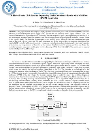
The increased use of rectifiers in critical loads employed by the information technologies, and medical and military equipment mandate the design of uninterruptible power supplies (UPS) with high -quality outputs The highly nonlinear currents drawn especially by high-power single -phase rectifier loads greatly distort the UPS outputs. The distorted UPS voltages cause generation of low dc voltage at the output of the rectifier loads, which causes high current flow, increased power losses, and possibly the malfunction of the critical load or the UPS. The distortion is resulted main ly by the voltage drop across the inductive element of the LC filter due to the non-sinusoidal current at the output of the inverter. In a UPS system, the inverter is responsible for synthesizing sinusoidal voltages fro m a dc source through the pulse width modulation (PWM) of the dc voltage. The inductive element here is needed to remove the switching frequency harmonics fro m the current waveform that are generated by the PWM operation of the inverter. The inductance value can be reduced if the switching frequency is increased. But, in practice, it has an upper limit at high power inverters due to the efficiency concerns and the switching device limitat ions. So, for th e selected switching frequency and the power level, an optimu m filter with a smallest inductance can be designed, but the distortion cannot be completely avoided, and the regulations and the customer specifications may not be satisfied. Despite several UPS topologies reported in literature, Figure 1 present a high level UPS b lock diagram used in this work. Main aspects of this UPS topology are: i) the load has two options to be directly powered, ii) DC power for the inverter stage is controlled on a rectifier stage, iii) the load is an external agent for the UPS system, being in princip le, an unknown factor for the inverter controller
Fig: 1. Functional Model of UPS The main purpose of this study is to achieve a high power quality on inverter stage, thus a three-phase inverter circu it @IJAERD-2015, All rights Reserved
70