NGM
BUILDING ARCHITECTURE THESIS
Politecnico di Milano

School of civil architecture AA 2020/2022
Master’s thesis in Building Architecture Professors
Prof.ssa Francesca Battisti Prof. Giovanni Dotelli Prof.Romano francesco Prof.Grigor Angjeliu Prof.Massimiliano Nastri Author Eden Nimni
Author : Eden Nimni, Eden.nimni@mail.polimi.it
DI MILANO
MIND ,MILAN
NGM MILAN E.N 2
POLITECNICO
NEW GATE
MILAN CITY & MIND DISTRICT
MILAN-MIND CONNECTIVITY
URBAN FABRICS
AN INNOVATION ECOSYSTEM
MIND- PRINCIPALS
MASTER PLAN’S GUIDELINES
LINEAR PARK
MIND WEST GATE
PARCO VERDE BLUE
HILL
THE EAST GATE
STRATEGIC MASTER PLAN
MUSEUM/RESEARCH CENTER
FUNCTION & CIRCULATION
PLANS AND SECTION
SLAB DESIGN
ROOF
NGM MILAN 3 INDEX ABSTRACT 6-8 ANALYSIS 10-25
CONTEXT 26-27
THE
STRATEGY 28-35
NGM
THE PROJECT 36-47
FLOOR
SUSTAINABLE MATERIALS 48-63
GREEN
FACADE DESIGN COLUMNS CLADDING STRUCTURAL DESIGN 64-103 STRUCTURAL LOAD CALCULATIONS SLAB DESIGN CONTINUOUS BEAM DESIGN COLUMN DESIGN CASE STUDY STRUCTURAL DRAWINGS SERVICE DESIGN 104-133 OPAQUE AND ROOF STRATIGRAPHY TRANSPARENT U VALUE SUMMER HEAT LOAD WINTER HEAT LOAD COLD WATER SUPPLY HOT WATER SUPPLY DRAINAGE SYSTEM
BIBLIOGRAPHY 133-135
ABSTRACT
Who look to the future” ( 2022 MIND).
MIND DISTRICT
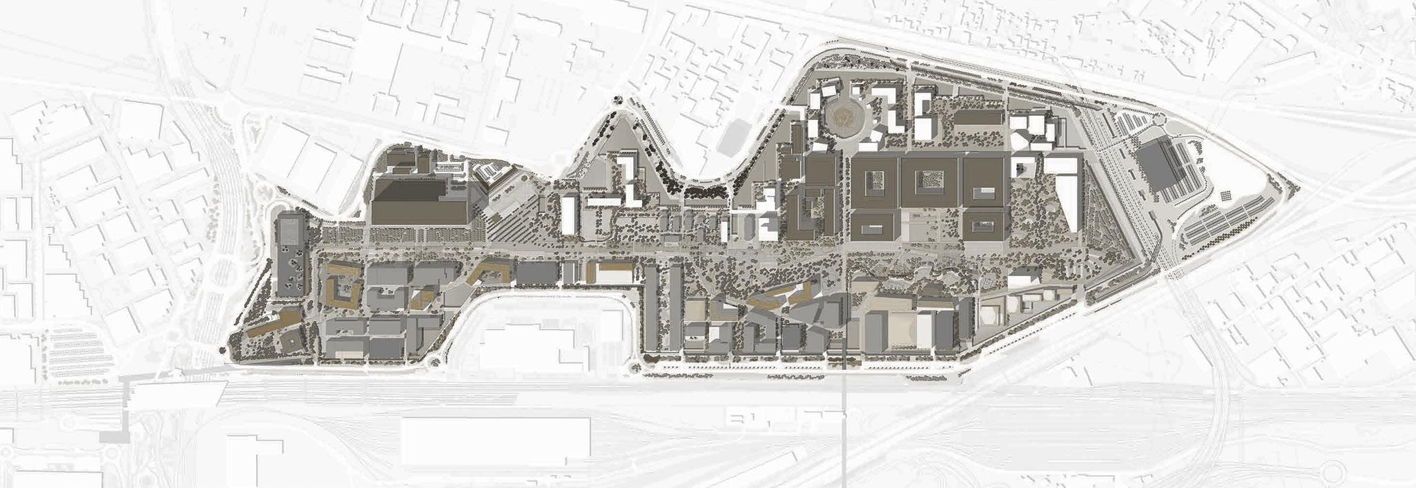
Originally developed to host Expo Milan 2015, the former World Exposition’s site is nowadays undergoing an overall urban renewal aimed at the rise of the future Innovation District. Unique in Europe for model and size, Mind’s design is based on sustainability, wellness inspired spaces, integration with nature.
The one million square meter area will host the headquarters of some public interest excellences, in addition to research, training, and business activities, services and commerce, residential compounds, open spaces and large parks, agglutinated along the main longitudinal axis from west to east, the Decumanus.
The infrastructural framework of the 2015 Expo Exhibition (the so-called Piastra, or Plate) offers a suitable frame for the development of MIND: an “infrastructure” to be re-used with the aim of containing the resources for the site “adaptation”.
THE EAST GATE
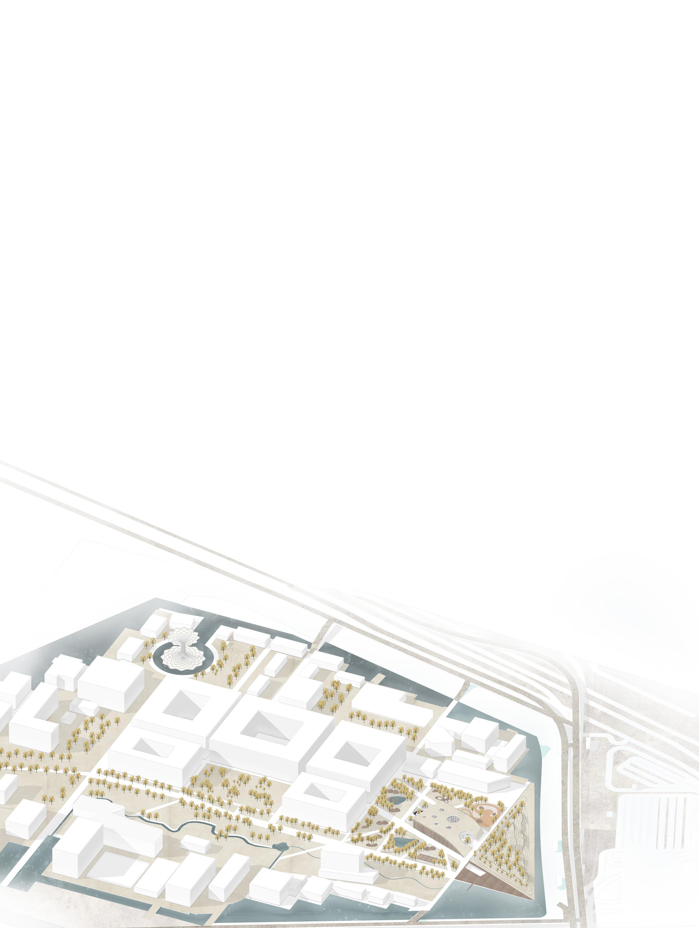
Within this frame, the East Gate sub-district exposes three main assets and zones: Science, Knowledge, and the Innovation Park. The area of intervention chosen for the thesis’s theoretical and project research is the northeastern entrance, the future Innovation Park, connecting MIND “inner” urban district with the water ring around it towards the highway and the main parking zone behind them. Identifying the potential of this site, the thesis project reinforces the current main axis and the east entrance through a further “public anchor”: the museum and research centre for new sustainable technologies in construction and design.
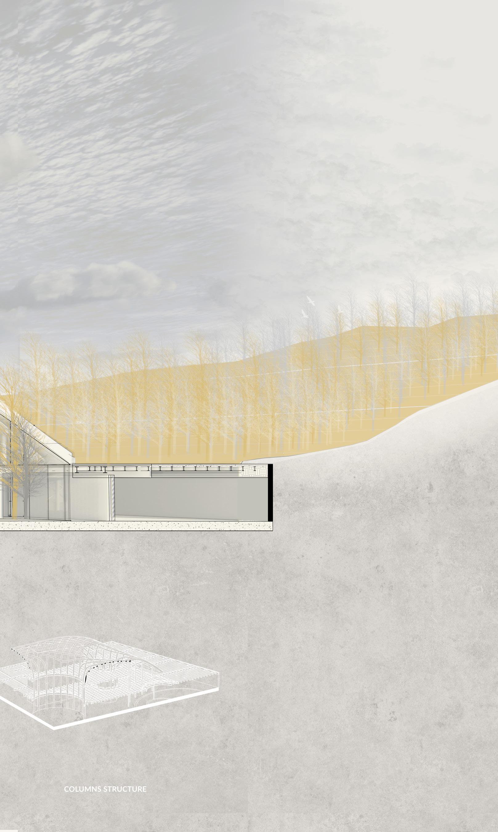
The green paths are redesigned to be better integrated with the adjacent urban anchors: the Statale University’s scientific campus to the west, the artificial green hill - serving as an acoustic barrier towards the highways - and east gate to the opposite side. The main path intersects the park from Mind’s main axis to the east, defining the project’s footprint. To create a relationship between the new intervention
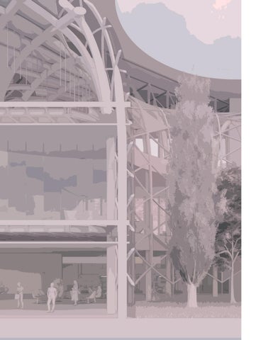
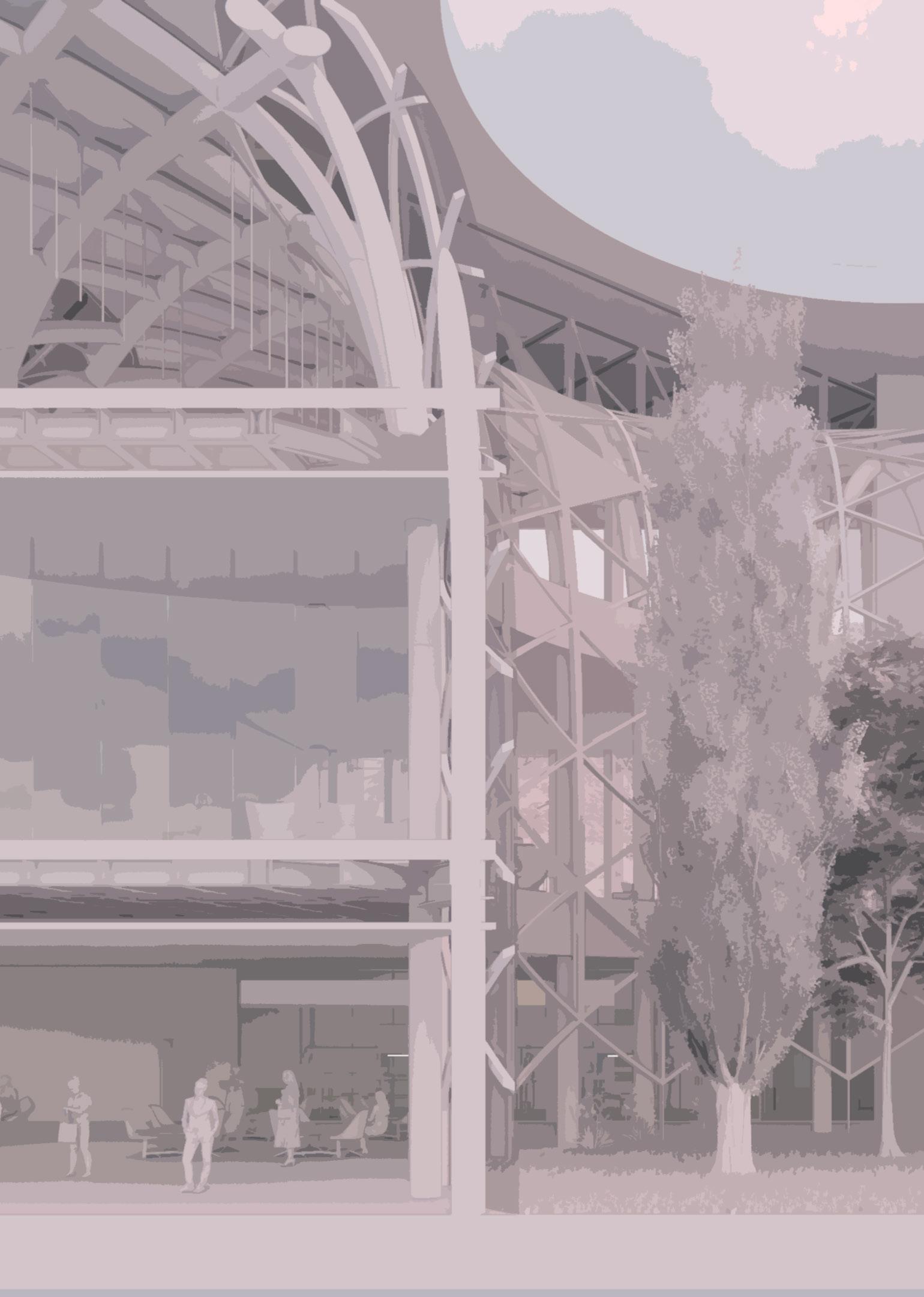
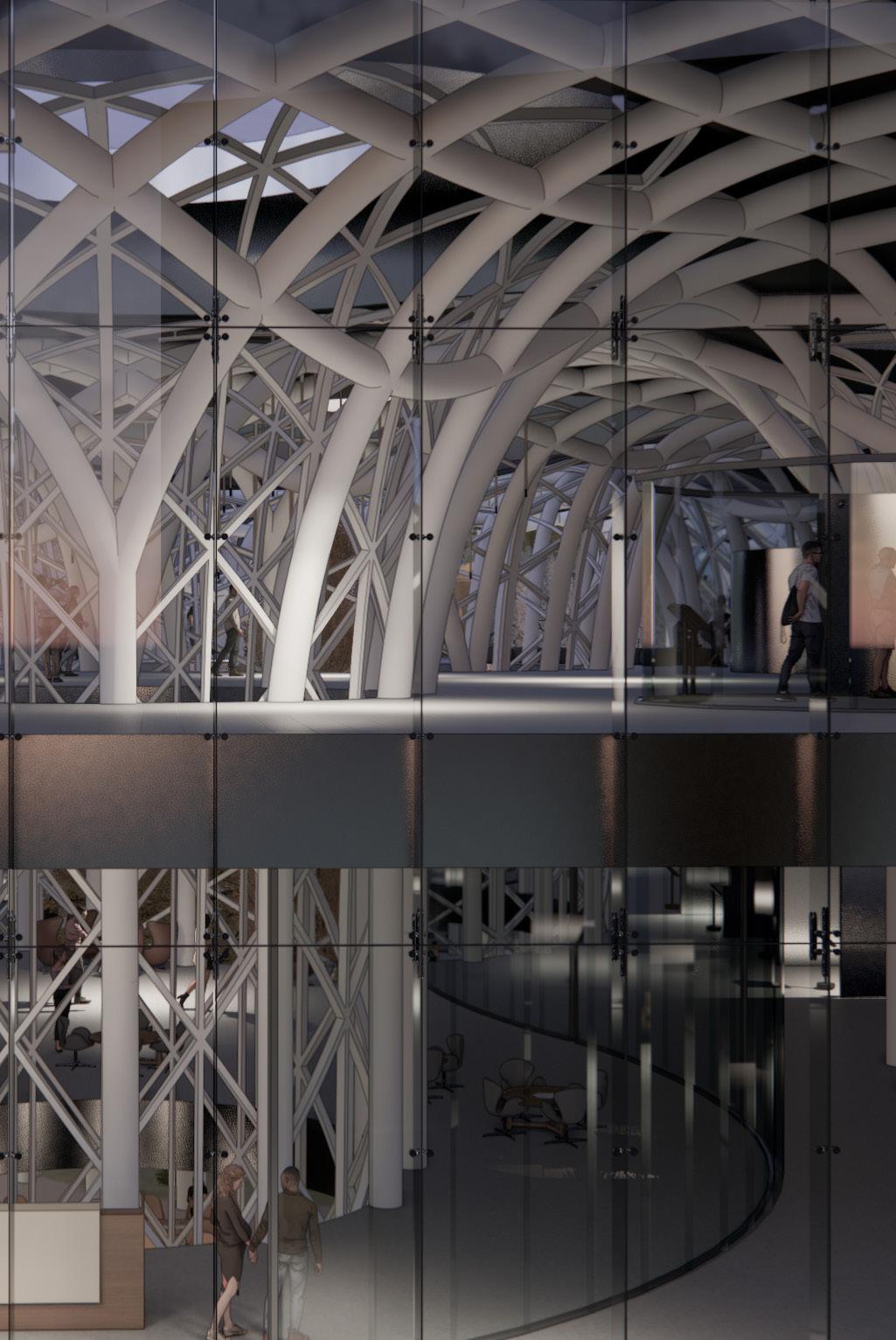
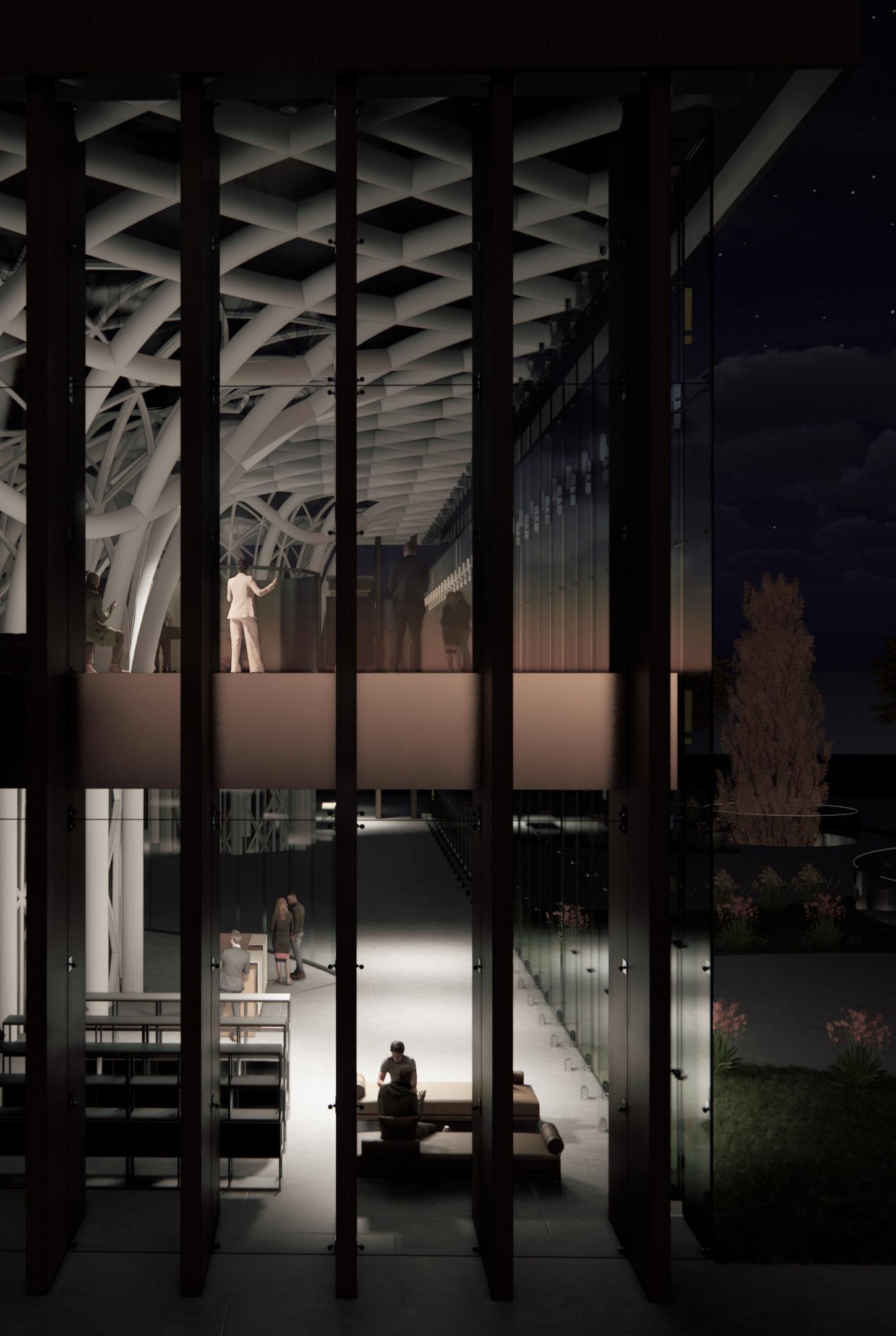
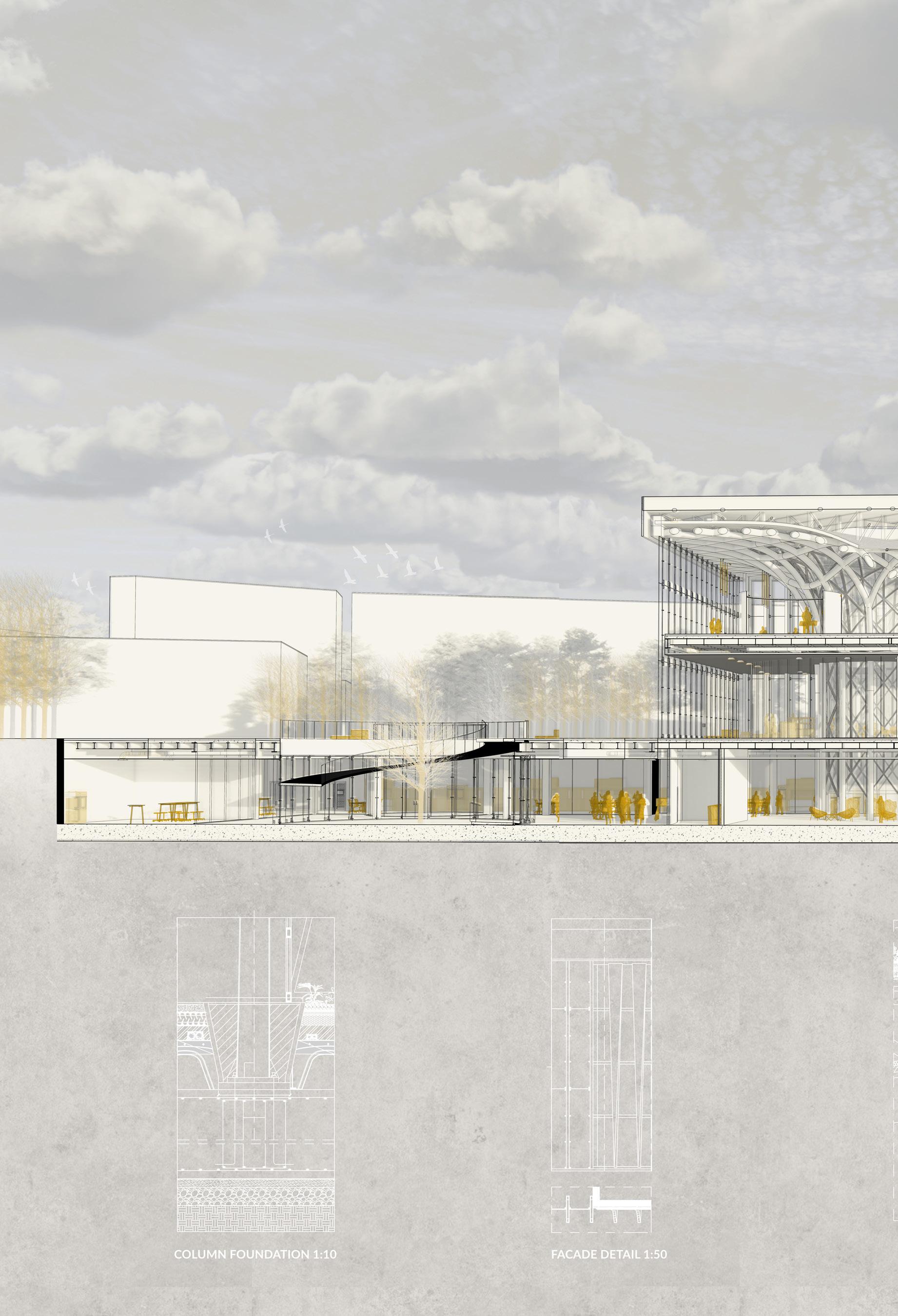
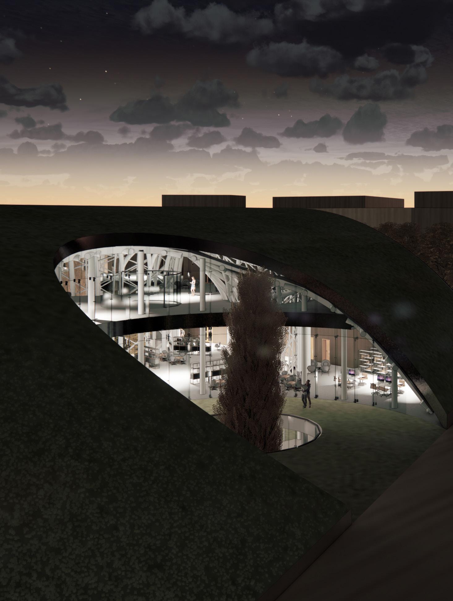
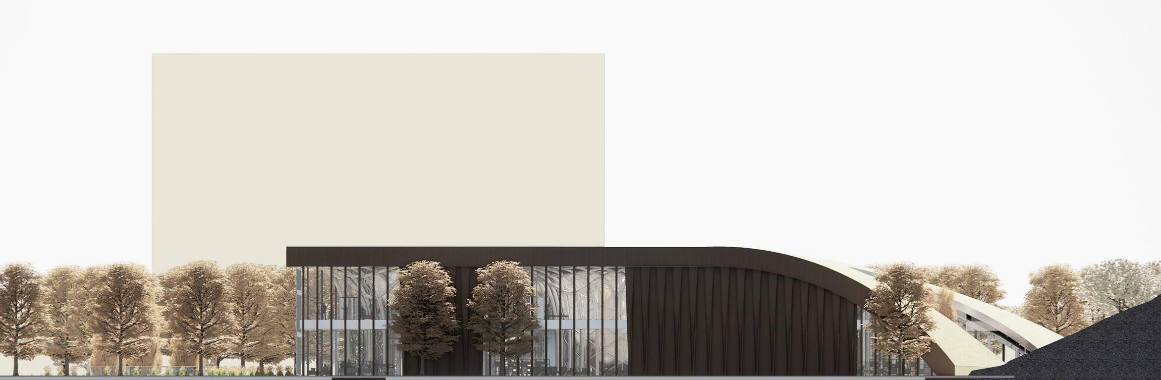
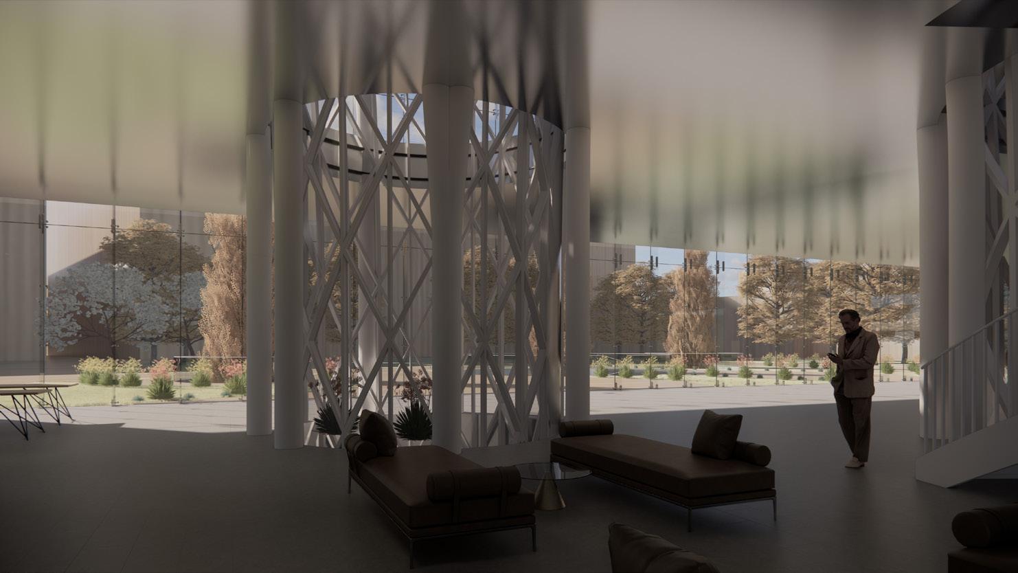
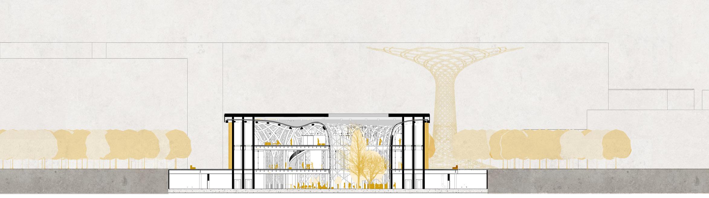
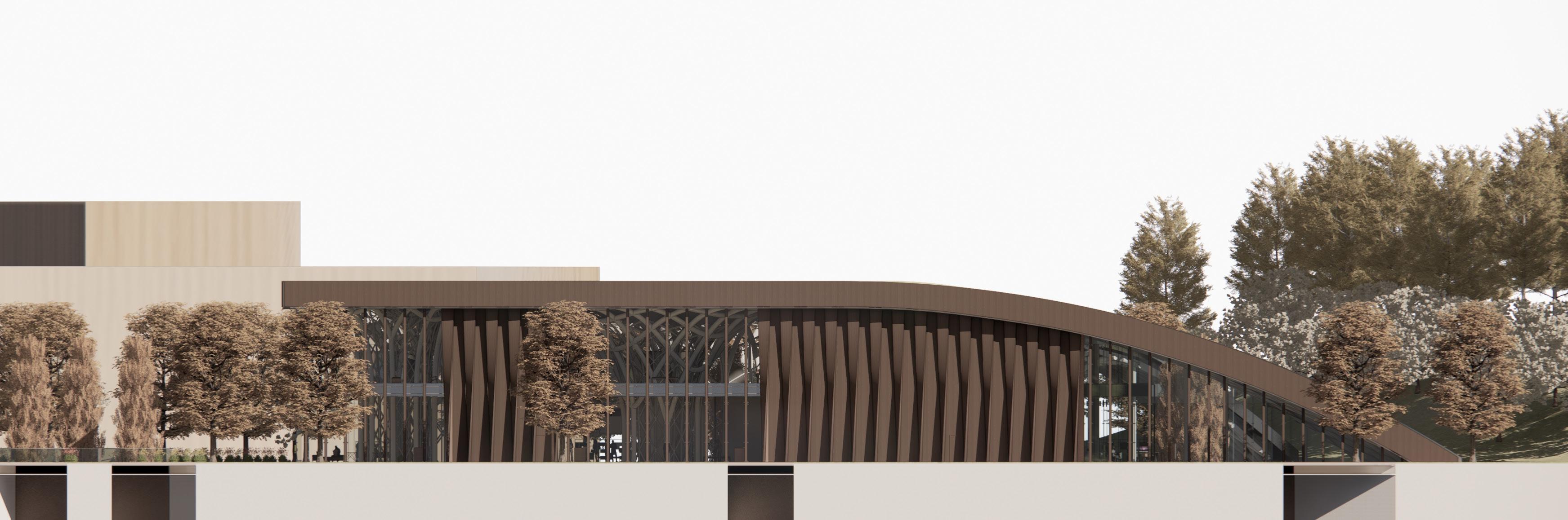
and the hill it is facing, the east façade is designed as a glazed elliptic opening, revealing the view of the hill from the east. The Opposite view, from the hill itself, Reveals instead a set of tree-like columns, supporting a curved green roof, ideal continuation of the park.
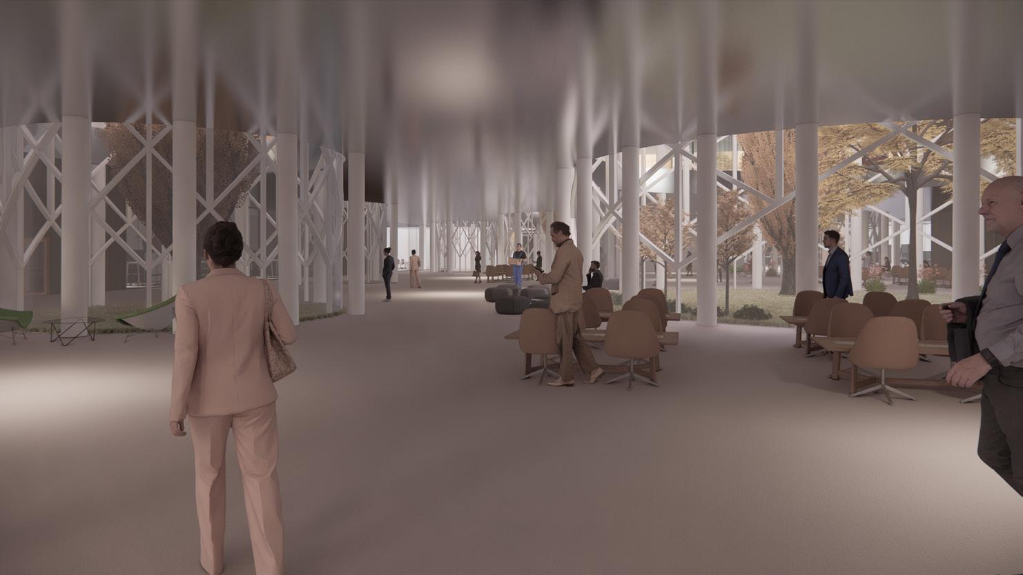
THE COLUMNS
The “Forest” of massive parametric design columns dictate the circulation within the building while providing sources of light and ventilation as they are used as inner courtyards, accessible from the building’s underground floor, where the research activities are concentrated. In front of the main façade of the museum, directly from the park, the main path introduces into this “inhabited terrain”, the innovation and research environment, through the main ramp which penetrates in a stenographic way into the hypophyseal level.
KEY WORDS: Innovation park,New gate,Parametric design.
NGM MILAN E.N 6
“MIND Milan Innovation district opens its doors to the ideas of those
NGM MILAN 7
MIND DISTRICT
Originariamente sviluppato per ospitare Expo Milano 2015, l’ex sede dell’Esposizione Universale è oggi oggetto di un complessivo rinnovamento urbanistico volto alla nascita del futuro Innovation District. Unica in Europa per modello e dimensioni, il design di Mind si basa su sostenibilità, spazi ispirati al benessere, integrazione con la natura.
L’area di un milione di metri quadrati ospiterà le sedi di alcune eccellenze di interesse pubblico, oltre ad attività di ricerca, formazione e impresa, servizi e commercio, complessi residenziali, spazi aperti e grandi parchi, agglutinati lungo l’asse longitudinale principale da ovest a est, il Decumano.
Il quadro infrastrutturale dell’Expo 2015 (la cosiddetta Piastra) offre una cornice adeguata allo sviluppo di MIND: una “infrastruttura” da riutilizzare con l’obiettivo di contenere le risorse per l’”adattamento” del sito.
ABSTRACT
LA PORTA EST
All’interno di questo quadro, il sottodistretto di East Gate espone tre risorse e zone principali: Scienza, Conoscenza e Parco dell’Innovazione. L’area di intervento prescelta per la ricerca teorica e progettuale della tesi è l’ingresso nord-est, il futuro Parco dell’Innovazione, che collega il distretto urbano “interno” di MIND con l’anello d’acqua circostante verso l’autostrada e il parcheggio principale retrostante. Identificando le potenzialità di questo sito, il progetto di tesi rafforza l’attuale asse principale e l’ingresso est attraverso un’ulteriore “ancora pubblica”: il museo e centro di ricerca per le nuove tecnologie sostenibili nell’edilizia e nel design.
I percorsi verdi sono ridisegnati per integrarsi meglio con gli ancoraggi urbani adiacenti: il campus scientifico dell’Università Statale a ovest, la collina verde artificiale - che funge da barriera acustica verso le autostrade - e la porta est sul lato opposto. Il percorso principale interseca il parco dall’asse principale di Mind a est, definendo l’impronta del progetto. Per creare un rapporto tra il nuovo intervento e la collina
su cui si affaccia, la facciata est è progettata come un’apertura ellittica vetrata, che rivela la vista della collina da est. La veduta Opposta, dalla collina stessa, rivela invece un insieme di colonne alberate, che sorreggono un tetto verde curvo, ideale prosecuzione del parco.
LE COLONNE
La “Foresta” delle colonne massicce di progettazione parametrica detta la circolazione all’interno dell’edificio fornendo al contempo fonti di luce e ventilazione in quanto sono utilizzate come corti interne, accessibili dal piano interrato dell’edificio, dove si concentrano le attività di ricerca.
Davanti alla facciata principale del museo, direttamente dal parco, il percorso principale introduce in questo “terreno abitato”, l’ambiente dell’innovazione e della ricerca, attraverso la rampa principale che penetra in modo scenografico nel livello ipogeo.
PAROLE CHIAVE: Parco dell’innovazione, Nuovo cancello, Progettazione parametrica
NGM MILAN E.N 8
“MIND Milan Innovation district apre le porte alle idee di chi Chi guarda al futuro” ( 2022 MIND).
ITALIAN
NGM MILAN 9
ANALYSIS
MILAN CITY & MIND DISTRICT
Milan-mind connectivity
Urban fabrics
An innovation ecosystem
MINDPRINCIPALS
Master plan’s guidelines
Linear park
Mind west gate
NGM MILAN E.N 10
NGM MILAN 11
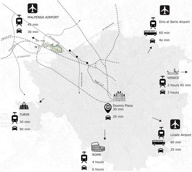
The new urban development of MIMD will include one of the most significant global innovation hubs, a testing ground for emerging contemporary living forms. The exceptional level of accessibility that distinguishes the Ex Expo 2015 site within the regional and metropolitan context is directly related to Milan’s strategic position as a node of European importance in the complex framework of national, European, and international connections.
MILAN-MIND CONNECTIVITY
In addition to being the hub of an airport system that comprises the airports of Malpensa, Linate, and Bergamo Orio al Serio, Milan is the major node of the highspeed system of Northern Italy, an infrastructure hinge within a macroregion that enjoys a vital position with respect to the transEuropean transport network.In terms of the regional framework, the metropolitan area of Milan is very attractive to nearly the entire region of Lombardy (as well as the neighboring provinces of Novara and Piacenza). Currently, it accounts for nearly one-third and draws about three-fifths of the region’s total
production values of mobility, or 16.4 million trips per day. The area undergoing urban regeneration thus forms a pivot between Milan’s urban fabric and the significant north-western territorial quadrant that grows along the Sempione axis. This area is characterized by the presence of significant transportation infrastructure, including roads and railways, whose upgrading represents the most significant infrastructural legacy of Expo 2015, infrastructural investments to be enhanced as a tangible component of the legacy.
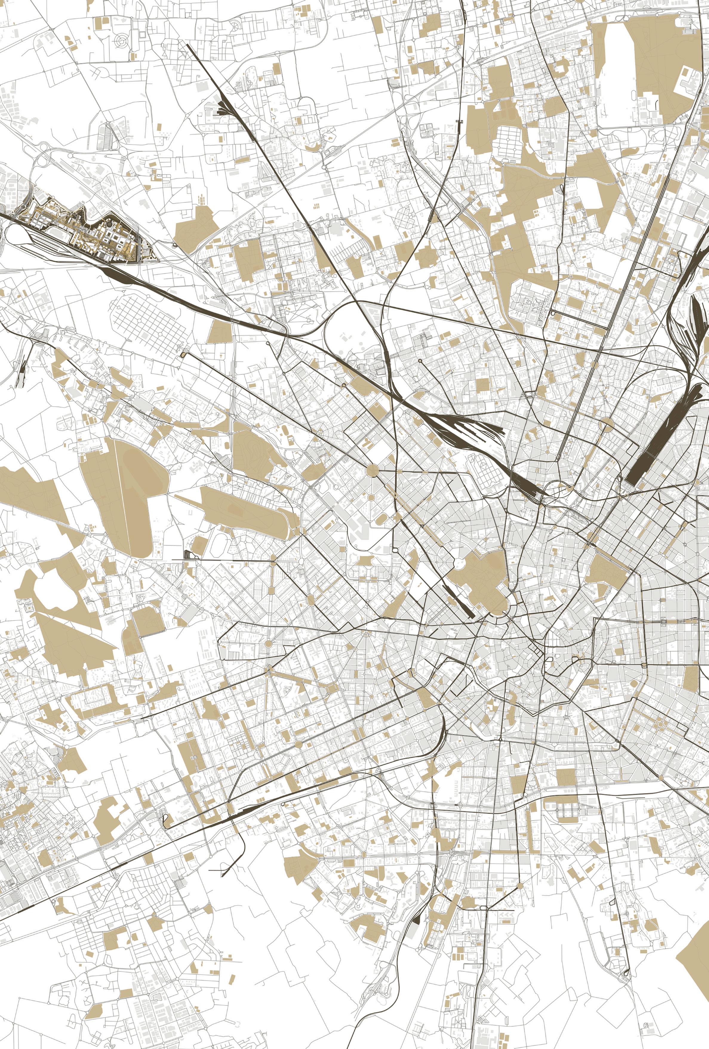
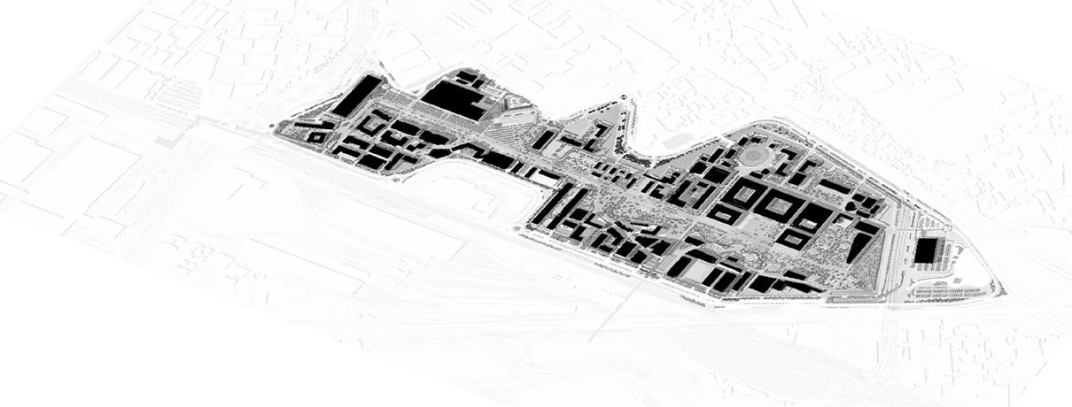
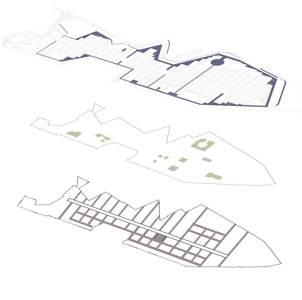
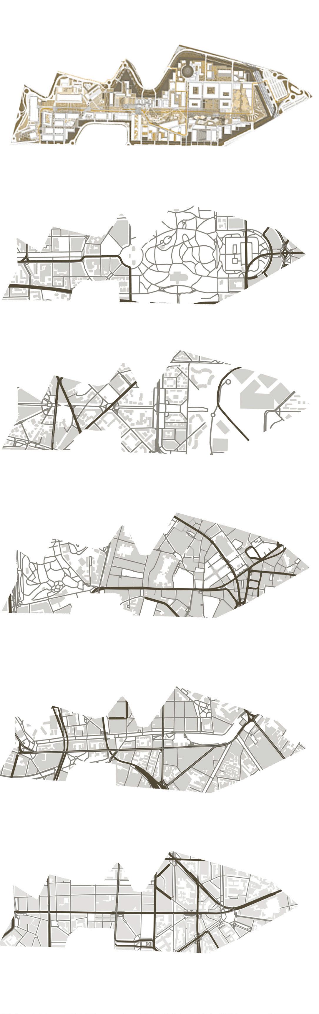
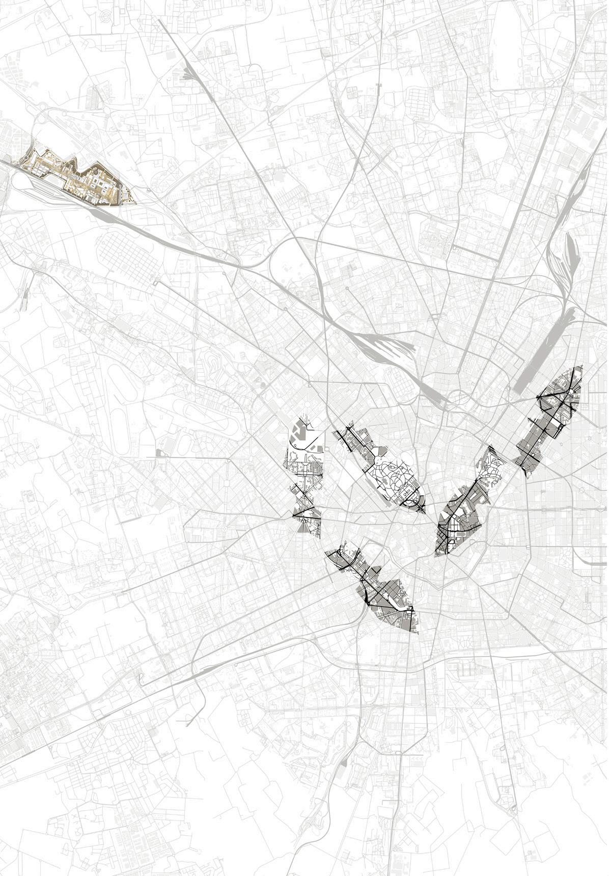
URBAN FABRICS
The Arco della pace/parco sempione zone, Navigilo canals, Corso Buenos aires, the center of Milan’s historical district and City-life zones can all be used to identify the city’s urban fabric. The overlap of both city fabrics allows for a comparison of past and contemporary urban evolution. The comprehension of MIND’s masterplan project’s growth, logic, and proportions is shown by overlaying the MIND district’s island-like design shape with the described urban fabrics of Milan.
NGM MILAN E.N 12
URBAN FABRICS,MILAN
VS OPEN SPACES
CANALS RING
OPEN SPACES
MASTER PLAN LAYERS
MIND MASTER PLAN
SEMPIONE
LIFE
(HISTORIC CENTER)
CANALS
NGM MILAN 13
R-EXPO
ROADS AND CONNECTIONS PUBLIC
WATER
BUILD
PARCO
CITY
DUOMO
NAVIGILO
CORSO BUENOS AIRES
AN INNOVATION ECOSYSTEM
The Post Expo urban transformation project includes creating a sustainable ecosystem as one of its primary goals. This ecosystem will be capable of fostering the emergence of a new community and serving as an example of a new urban catalyst, one that is distinguished by a significant functional and social mix ,connected not only to Milan’s center but also to the nearby epicenters. Thus,MIND project will be developed to welcome international excellence and a Science and Technology Park distinguished by the capacity to connect technical know-how and humanistic knowledge within the original framework of Milan’s “polytechnic culture”.
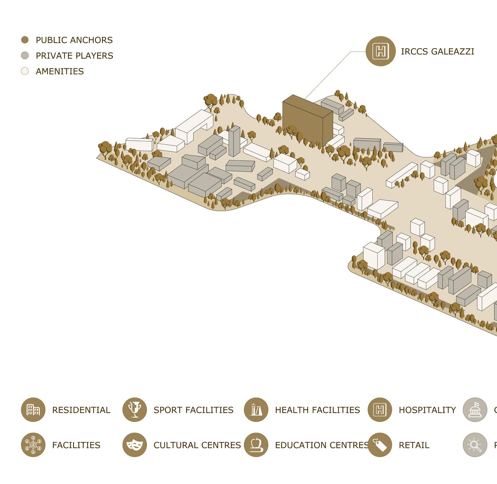
MIND’s functional mix ensures that a variety of users participate in activities in the area during the course of the day. The Human Technopole, Hospital Galeazzi, Fondazione Triulza and Unimi scientific departments campus are the 4 public institutions that are fostering the advancement of MIND and will spark an influx of new businesses and projects.
NGM MILAN E.N
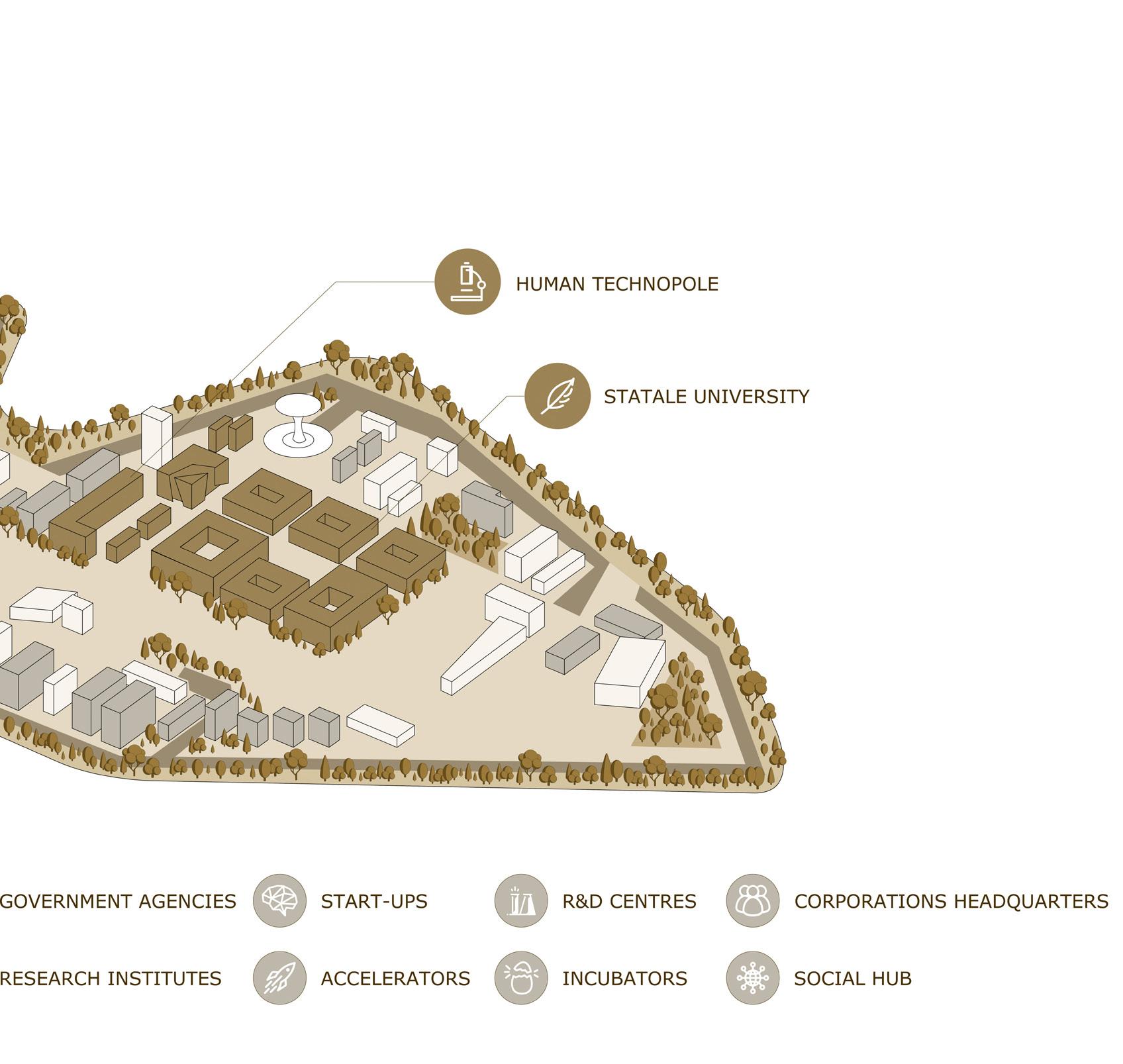
THE HUMAN TECHNOPOLE
A 35,000 sqm of a national and international hub incorporating research and hospital functions. The hub sets its goals to tackle cancer and neurogenerative, developing personalized medicine. It contains buildings ,and 7 research centers with a focus on agri-food and advanced technologies. the structure consist of two functional and flexible volumes, which will develop around a Common Ground, the focal point from which the entire construction is generated, a central space that will be the heart of the building both for its location and for the its function.
Starting from the ground, the common space will unfold within the ten floors, creating an interconnected unicum that reaches up to the roof, creating new spaces for aggregation and relaxation.
The first to ninth floors will be dedicated to laboratories and administrative offices, while the top floor will host refreshment areas, classrooms for training activities, representative meeting rooms, executive offices and terraces with direct access to the accessible green roof.
STATALE UNIVERSITY
A 150.000 sqm of a modern scientific education and research campus aiming for the most advanced international standards for teaching, research and interaction with the privet industry. Containing 5 buildings, of which 4 are scientific faculties. The buildings pay homage to the Ca ‘Granda, the fifteenthcentury brick building designed by the Renaissance architect Filarete, which now houses the headquarters of the University; the facades were designed with an innovative construction technique, with each brick positioned individually by a robotic arm and treated as a pixel within a large bas-relief: the result will be a three-dimensional tapestry with textual and visual content.
GALEAZZI RESEARCH HOSPITAL(IRCSS)
A 150000 sqm research hospital ,gathering the orthographic field of IRSCC and the cardio-thoracovascular field of the Sant Agostino clinic institution. With 16 floors of height, It has been designed following the future hospital concept, paying attention to environmental sustainability, renewable energy and minimizing waste and consumption, but also noise and pollutant emissions. Great attention has also been paid to comfort, humanization of interior spaces and natural lighting.
Within this context, the task in hand for this thesis was to study the existing masterplan in search of a strategic area for an intervention in a form of a research/scientific complex, or a cultural center. a project that will express the values of Mind and will integrate with the overall masterplan.
NGM MILAN 15
NGM MILAN E.N 16 ANALYSIS MIND- PRINCIPALS PRIMARY INTERIORS CROSSINGS SECONDARY INTERIORS CROSSINGS URBAN OPEN SPACES NEW WATER CHANNELS THE PODIUM INNER COURTYARDS HIGH ELEMENT ALIGNMENTS MARGINS COMMERCE, COMMUNITY & SERVICES 10 PRINC. 1 2 3 4 5 6 7 8 9 10
COMMON GROUND
NGM MILAN 17 FOOTPRINT ALIGNMENTS MARGINES
NGM MILAN E.N 18 8080 16 1616 Piazza delle Ar Piazza del Benessere Piazza delle Culture Piazza Italia Piazza dell’InnovazionePiazza del MercatoContadino Piazza d’acqua 01 02 03 04 05 06 07 08 09 10
Any open area within the Lot, arranging the building’s various components in accordance with their respective ties.
Any notable elements with a maximum height of 300 meters that could be located, either from the ground or from the Podium.
Building alignment in relation to open spaces.
Relevant view of the buildings towards the open spaces.
Possible large construction,designated to preserve urban links through various sorts of alignment.
A service and pedestrian link between the interior spaces of the site and the perimeter through the feasible implementation areas.
Potential crossing infrastructure between Areas.
Any accessible public open areas that are relevant to the urban design.
Potential canal system implementations at the site.
Localization of accessible facilities that enable and implement the usage of public spaces.
NGM MILAN 19
PRIM. INTERIORS CROSSINGS SEC. INTERIORS CROSSINGS URBAN OPEN SPACES01 02 03 NEW WATER CHANNELS04 THE PODIUM05 INNER COURTYARDS HIGH ELEMENT ALIGNMENTS06 07 08 MARGINS09 COMM. COMMU. § SERVICES10
01_PRIMARY INTERIORS CROSSINGS
Principals:
◊
crossings - primary / secondary- for greater accessibility.
◊
Guarantee the connection between the external road network (loop) with the main interior spaces (ex: Decumano)
◊ Continue the existing path lines within the site forallow, where possible, a physical and visual continuity between thecontext and the new
◊ Allow the crossing of the Areas without having totravel too long, avoiding the sense of barrierurban
◊ Ensure privileged / visual perspectives of landmarks
◊ Ensure the creation of large systems of collective space
02_SECONDARY INTERIORS CROSSINGS
Principals:
◊
Reproportion the Expo plan’s grid transversally in order to adapt it to new purposes.
◊ Allow the crossing of areas on secondary roads to provide more options and diversified journey times.
◊ Connect two or more main crossings.
◊ Encourage the growth of activities and the presence of pedestrians for a stronger sense of security.
03_URBAN OPEN SPACES
Principals:
◊ Create relevant public spaces as part of the urban design
◊ Relate public space with
Characterize the areas with aspects that make them distinctive and readily distinguishable (a central element that focuses attention might invite visitors to explore the space).
◊ Maintain the vibrancy of the entire fabric by offering varied activities at different times of day and ensuring at least one busy front of the buildings overlooking the open space.
04_NEW WATER CHANNELS
Principals:
◊ Contribute to the characterization and usability of urban spaces.
◊ Reduce the site’s heat island effect by integrating a rainwater collection, storage, treatment, and reuse system.
05_THE PODIUM
Principals:
◊
Define the alignments and morphology of open space
◊ Host functions with a more direct relationship to urban spaces
◊ Connect the high elements to each other and promote interactions and relationship.
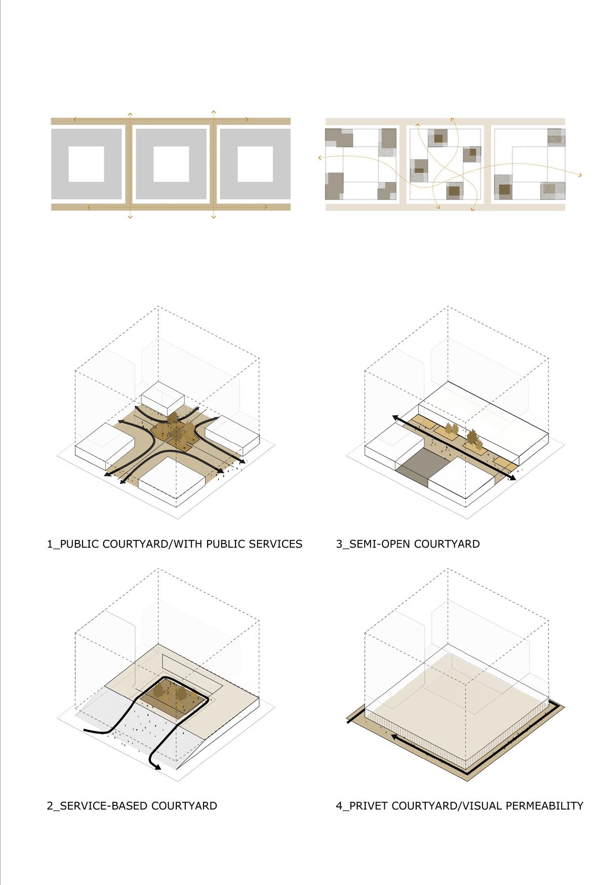
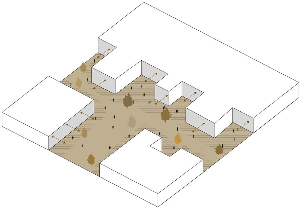
06_INNER COURTYARDS
Principals:
◊ Ensure sufficient permeability: courts might be entirely public, partially open, elevated with
NGM MILAN E.N 20
◊ services and private courts, however with guaranteed visual permeability.
• Maintain the continuity of public spaces within the building while giving it a more private sense.
• Establish ties with the foot of the buildings that will house the program’s ‚active lobbies,’ or the most public and communal operations, in order to provide informal surveillance and a greater sense of safety.
07_HIGH ELEMENT
Principals:
◊ • Ensure the best perspective and the most effective form factor in connection to the various functional programs.
• Maintaining the environmental quality of courtyards and open places (sun exposure, ventilation, etc.)
• Establish a good relationship with nearby open areas, which may be regulated through the Podium.
• Help to build a network of visual references and focus points that perceptually shape the urban environment.
08_ALIGNMENTS
Principals:
◊ Define specific correlations with respect to the Elements that characterize the site.
• Create recognized metropolitan sceneries using a variety of elements.
◊ Create recognized metropolitan sceneries using a variety of elements.
09_MARGINS
Principals:
◊
• Provide appropriate openings to ensure a good view of the public environment.
• Contribute to the definition of the urban landscape by introducing a distinct rhythm in the façade and its architectural components.
• Promote public space activation by direct interaction with pedestrians in the area in front of it.
10_COMMERCE, COMMUNITY, § SERVICES
Principals:
◊
• Commercial activity must be positioned where there is the possibility of informal surveillance as a result of nearby activities.
• It has to be visible from a distance.
• Situated near the busiest crossings
• Adequate circulation must be possible around the structures.
• Extend the structure into the surrounding public area to encourage parking and a welcoming environment.
NGM MILAN 21
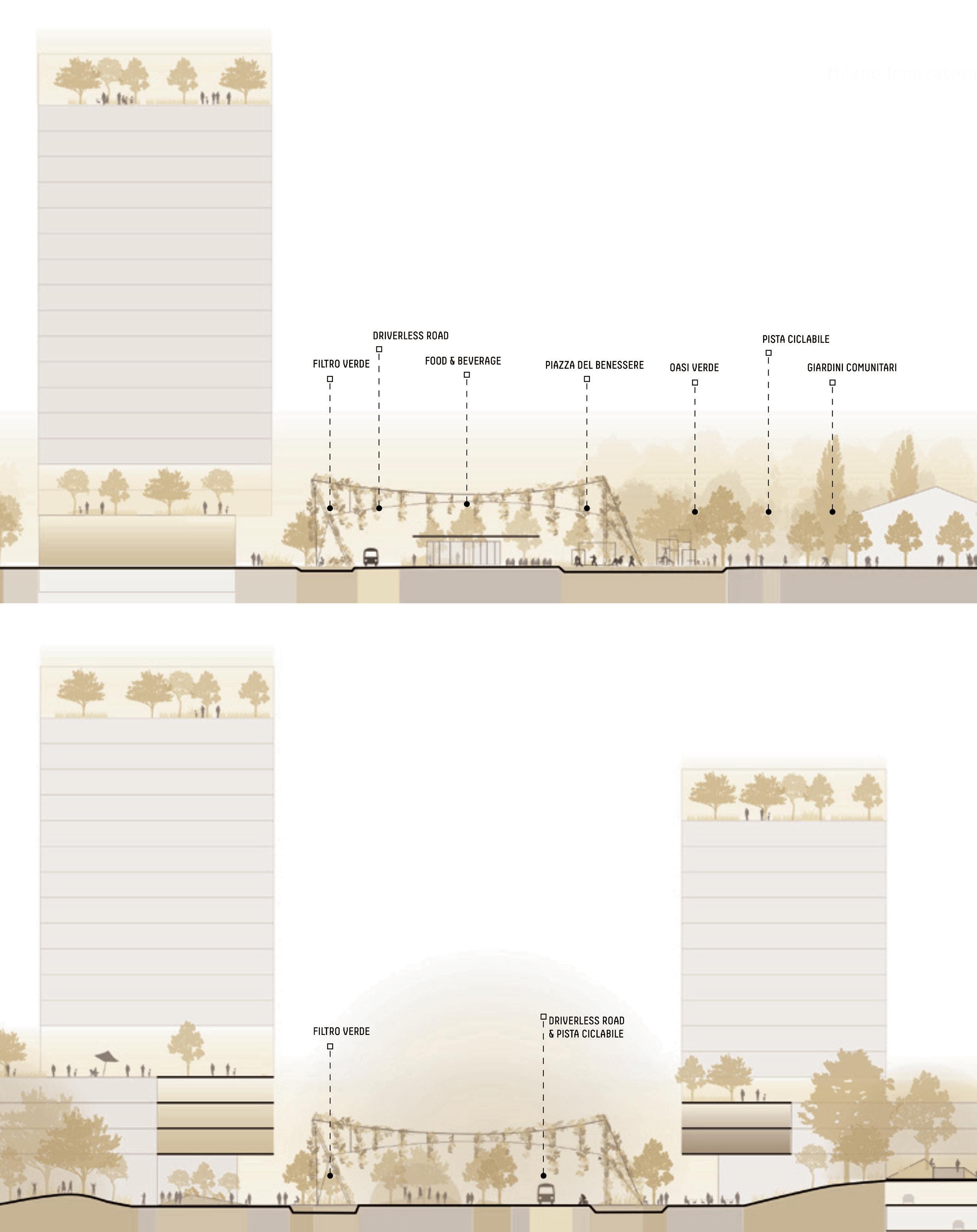
LINEAR PARK ON THE DECUMAN
An important public intersection, a pillar of social aggregation highlighted by the presence of nature.
Principals:
◊
Verify the link between the site’s various polarities.
◊ Using landmarks and focal lines, establish visual links with the rest of the site and the surroundings.
◊ Physically or visually connect the site’s urban green spaces to encourage the illusion of a massive urban green system of high quality.
◊ Reduce the corridor impression by generating spaces with filters, dilations, and compressions, maintaining continuity and new linkages between the sections involved.
◊ Host public activities and common areas to foster the formation of a cohesive community.
◊ Ensure physical and visual continuity of the different paths,
◊ promoting the coexistence of soft mobility vehicles (pedestrian,
◊ cycle path, driverless).
NGM MILAN E.N 22
NGM MILAN
A site analysis exposed 3 main divisions of the master plan as:science, knowledge, and the innovation park.
The chosen area of intervention of this thesis’s theme was the east-north entrance, which is currently the innovation park. The east gate connects Mind district with the water ring around it towards the highway and the main parking zone of the district’s north part.
Acting as an important reference to this choice is the West Gate, The west gate is a mixed-use development within MIND district that marks the western entrance. It includes a variety of green spaces that aren’t only decorational but are an important aspect of the conceptp; Boundaries between indoor and outdoor settings are blurred. The project is mainly about developing a neighborhood based on a new model of social relationships in which people can live and work; Offices, residential, services: a space based on the mix of functions. The goal of West Gate is to create a modern, mixed-use neighborhood. Innovative smart structures and environmentally friendly architecture are housed
there for an urban regeneration best practice example.
MIND WEST GATE
NGM MILAN E.N 24
NGM MILAN 25
CONTEXT
PARCO VERDE BLUE
The green-blue belt, relegated to a rich separation during Expo2015 consisting of the perimeter green, reacquires an urban character in MIND, delineating new areas for socializing and being, but attentive to that ecological environmental renovation essential for a contemporary scientific theme park.
The fitted connecting park makes its way through the green belt: a 1 km walk that runs on the north side from Cascina Triulza to the planned skate park beneath the viaduct, enhanced by the presence of the Expo2015 Children Park. The water channel is an essential component of the green-blue system, fed by the Villoresi canal and connecting to the north with the Groane Park and the cycle system of the long Canale Villoresi.
Water is an important component of the Site: The canal expands inside MIND in a ring along the circumference with various dimensions and identities
(canals, basins, docks, and lakes), with a total length of about 4.4 kilometers and a total area of the liquid mirror of roughly 83,000 square meters. They are strongly linked to the created wetlands for Expo2015 at the canal to enable the purification of rainwater from the Site’s superficial run-off.
To ensure conformity with the qualitative characteristics of the receiving water bodies, MIND project has allowed for the re-functionalization of them, keeping the largest number and integrating them with naturebased solutions.
THE HILL
„La collina mediterranea”
The Mediterranean Hill, with a base area of 8723 square meters, is located at the site’s eastern end. It is one of the fundamental landscape monuments developed for Expo2015, rising at the ends of the Decumano and representing one of MIND’s cardinal points of reference.
NGM MILAN E.N
NGM MILAN 27
STRATEGY
STRATEGIC MASTER PLAN
STRATEGIC MASTER PLAN
THE EAST GATE VS THE WEST GATE NGM MUSEUM/ RESEARCH CENTER LANDSCAPE & AMENITIES
NGM MILAN E.N 28
THE WEST GATE
Human Technopole
Campus Scienze UNIMI
As previously explained, the MIND masterplan sets various anchor points to reach the overarching goal of an inventive, futuristic area that will bring a new way of life to Milan. These projects shape the urban environment and impact future development in the district, providing a distinctive backdrop for MIND. The major elements of each of these initiatives, as well as their roles within the masterplan, are outlined below.
Ircss galeazzi-sant’ambrogio
With a multi-specialist vocation, the hospital’s development thrives to promote innovation and growth by providing ample space for university teaching and scientific research: in 2006, the Galeazzi Orthopedic Institute received the prestigious I.R.C.C.S. from the Ministry of Health for research in the field of musculoskeletal diseases. It contributes significantly to MIND’s goals as a Science&Technology center.
Human Technopole’s overarching goal is to develop innovative strategies to promote human health through a multidisciplinary and integrated approach to the study of human biology. it is a key anchore to MIND as it goes hand in hand with the distrcit’s principals of innovation and knowledge.
Campus unimi
Creating an expansion of campus unimi, one of Milan’s main universities, in the MIND district is an important strategic move to attract young tenants and a step forward in developing a new international hot spot
Parco verde blue
The green-blue belt from the east that continues in the shape of an artificial hill serves several purposes, including noise reduction from the busy E64 highway, providing a panoramic view of the entire district, and
contributing to the district’s sustainable eco-system, which is one of its main distinguishing features.
The west gate
Offices, residential, services: a space based on the mix of functions, with the purpouse of a common ground principal and innovative urban sapces.
29
IRCSS GaleazziSant’Ambrogio
The Hospital for Health of the future
Fondazione Triulza
The Third Sector hub for social innovation.
MIND Village
A global mini-district for innovation.
The Italian institute for research on Life Sciences for innova tion
The future home of the scientific faculties of
Statale
University
PARCO VERDE BLUE
The
system of gardens and canals around MIND
Commertial work space,built-to-rent,light industri al,hotel & placemaking retail
THE WEST GATE
Commertial work space,built-to-rent,light industri al,hotel & placemaking retail

THE WEST GATE VS THE EAST GATE
The East gate is a parallel development, defining the entrance to mind from that direction, using the west gate as a point of reference. A legacy from the R-expo concept, „parco verde blue,” is being expanded as part of the urban strategy for the new east entrance, along with a cultural and educational facility that will blend in with the park surrounding it.
The west gate serves as a landmark inside the district, maintaining the masterplan guidelines and presenting a new way of living. Studying the various uses and developments of the west gate was critical for constructing the concept of the East gate. Referencing the role of a gate inside the district, the initial thought was to continue the landscape integrated within the build area, while connecting to the existing park area and maintaining the high ratio of green to the development suggested in the previous mester
plan. as mentionaed before ,The east gate, like the west, will mark the entrance from it’s direction, but instead of offering high density build spaces, it will serve as an extension of the current Parco verde blue, offering various ‚common ground’ amenities to incomers. The NGM project, a museum/research facility, will serve as an ancor point within the east gate, integrated within the park, and an attraction point.
E.N 30
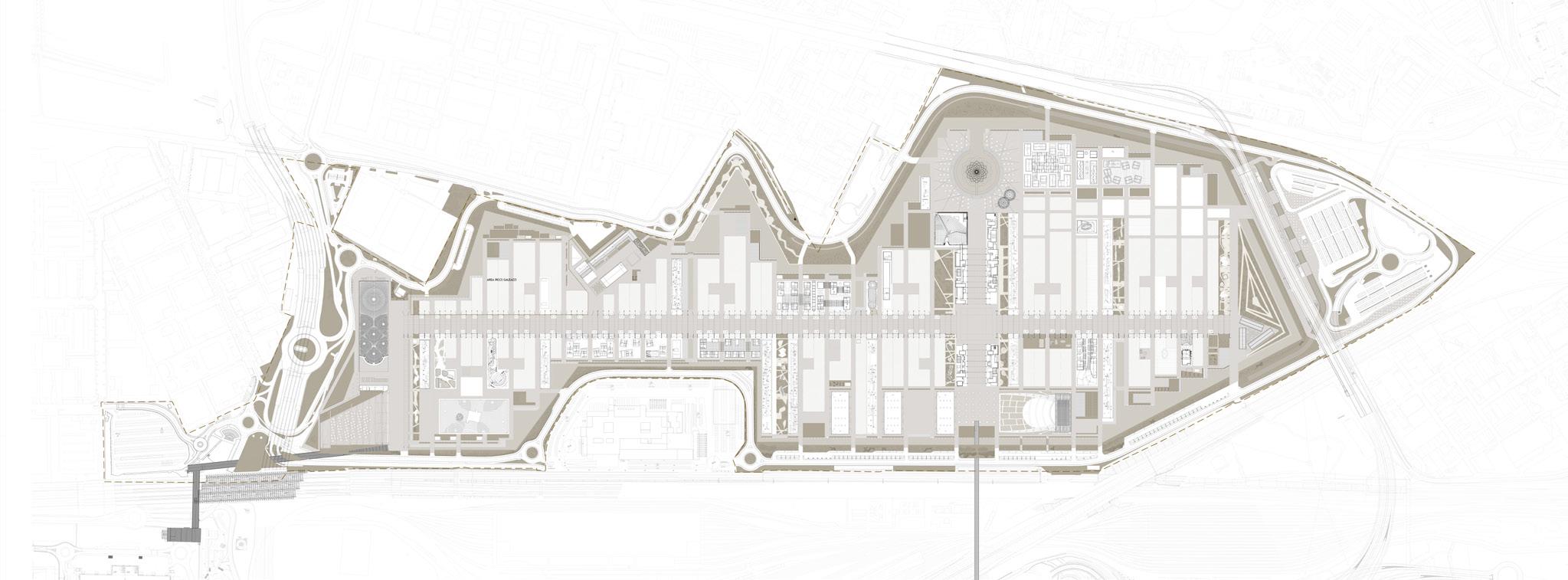
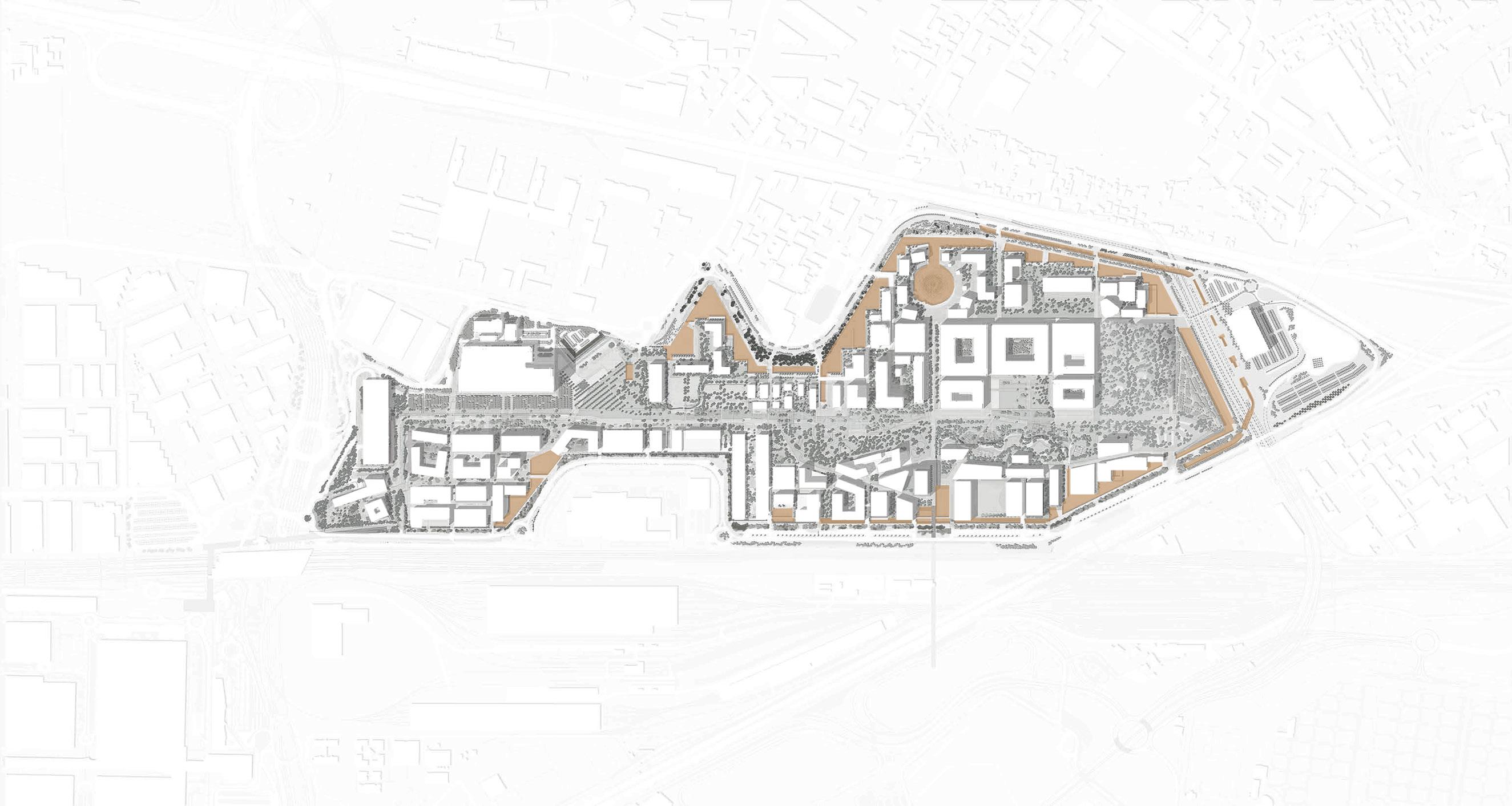
THE EAST GATE chosen project area -Integrated research and cultural center amid the network of parks and waterways surrounding MIND
THE EAST GATE STRATEGIC PLAN
The strategic plan makes reference to two previously stated key landscape components: the green blue park and the Mediterranean hill; the new east gate is next to the east entrance, with the Mediterranean hill bordering it from the district boundary direction. It is, in essence, an extension of the park and green fabric that wraps around the hill, forming a green rectangle between the hill and the UNIMI buildings.
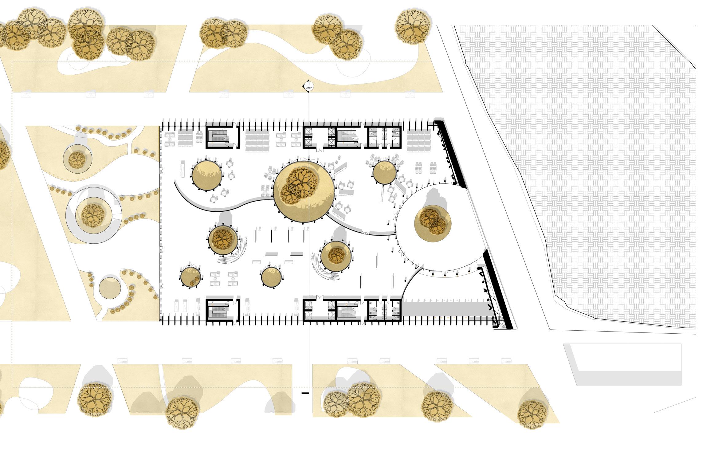
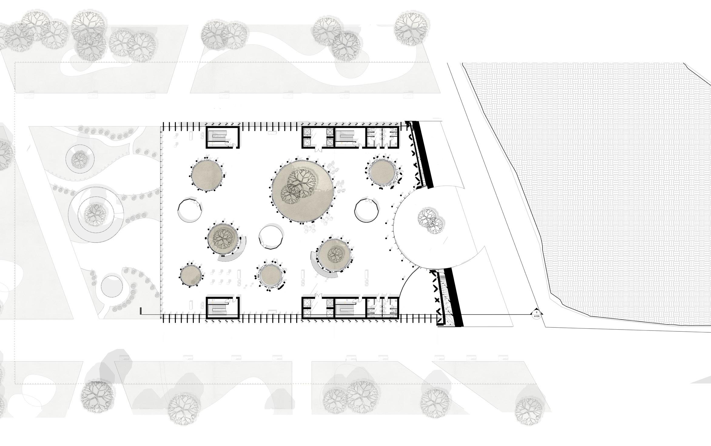
The new park will incorporate additional green public areas and will then be divided into specific alignments with the hill in the east and the Milan University in the west, defining the footprint of the NGM building. It was possible to incorporate the east facade with the slope in front of it by orienting the building’s east front to face the hill and developing inner courtyards on the ground level.
31
center (green roof) Laboratory Building
THE EAST GATE Incorporating a museum/research center that is oriented toward the east entrance and extending Parco Verde Blue.
Parco verde blue
STRATEGY
LANDSCAPE DESIGN
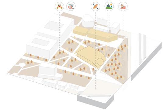
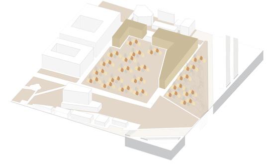
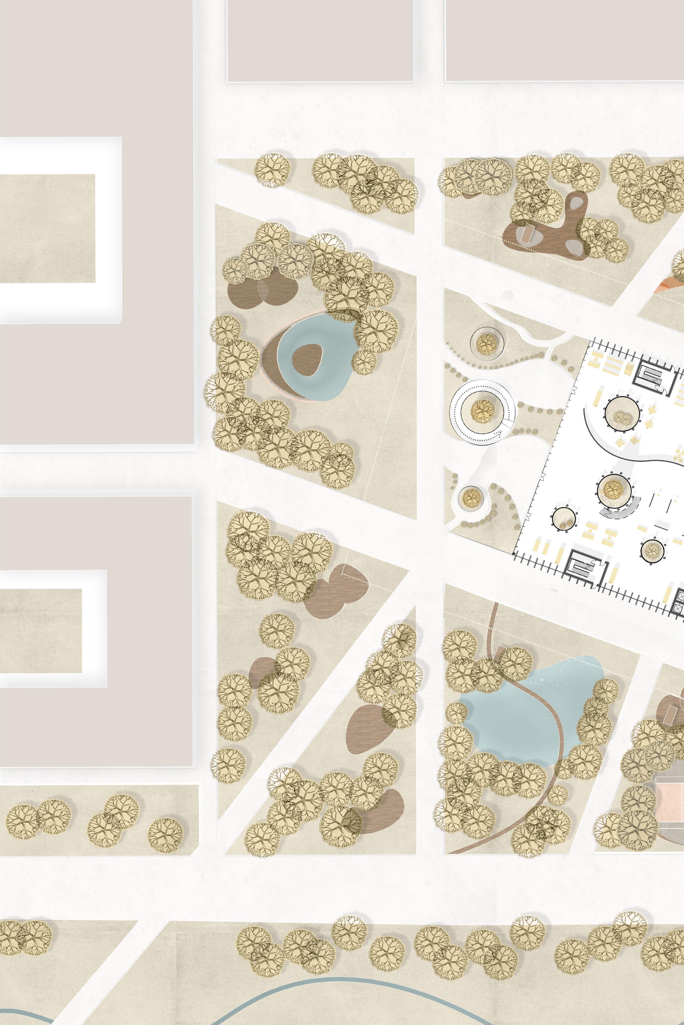
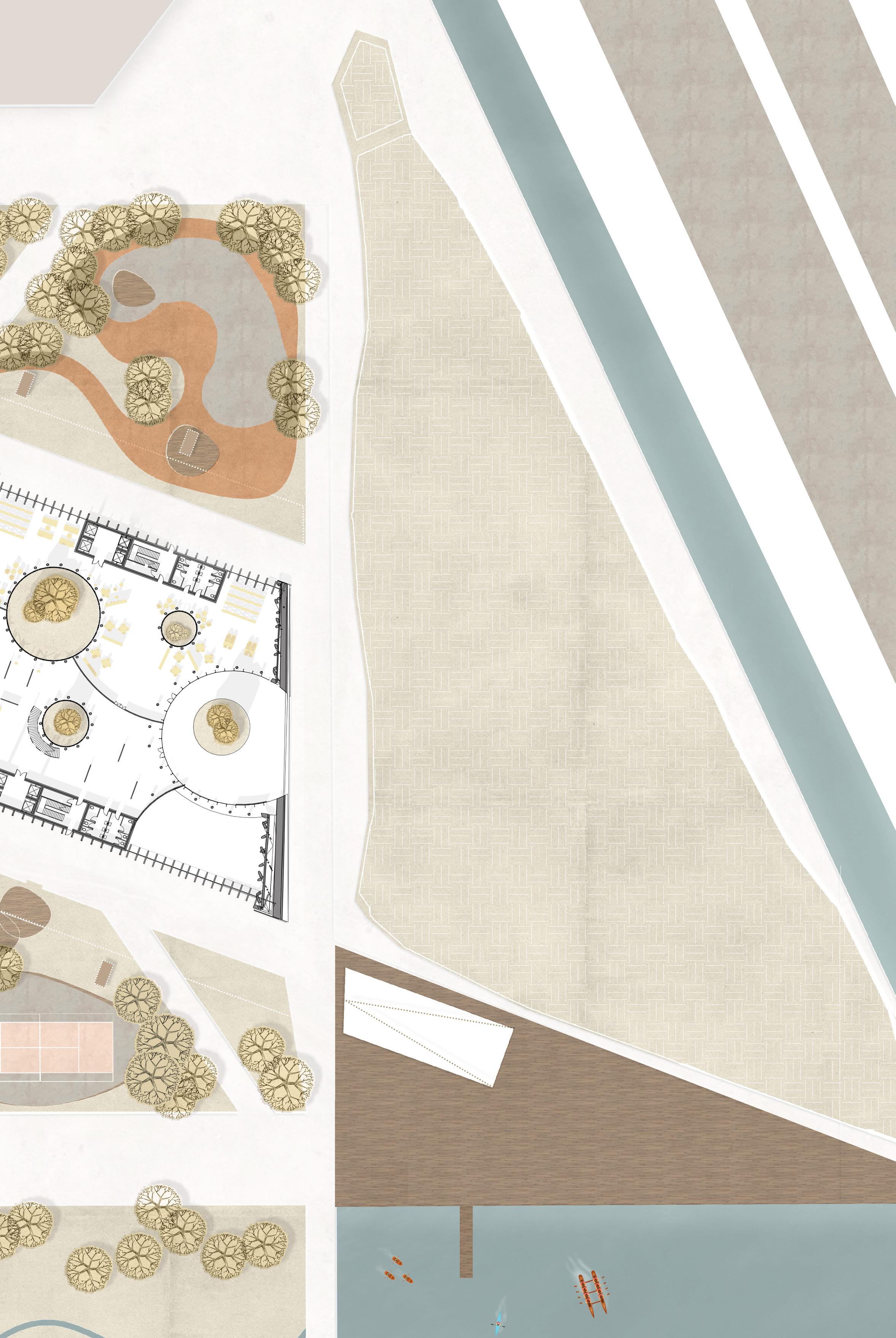
The landscape design of the December 2021 concept inspired the internal organization of the green patches around the structure. The project focuses on the design of innovative urban spaces in the form of various integrated utilities within the ‘raddure’ ,clearings ,that are spread throughout the green sections, imitating the organic organization of a forest.
The various utilities are positioned within the clearings as part of the forest-like landscape concept. Each clearing investigates a distinct urban space with various purposes, utilizing Mind’s concept of common ground.
WATER PIAZZAS
A water piazza, placed in front of the NGM building, acts as an outdoor attraction with seating areas and a water fountain. It is intended to draw visitors to the open spaces surrounding the
building by emphasizing pedestrian movement and human interactions.
RELAXATION AREAS
Relaxation areas are distributed among the clearings, containing wooden decks for people to rest on and enjoy the greenery around them
ACTIVE URBAN REALMS
Active urban realms are areas dedicated for sporting activity. The role of these areas is to combine open-to-all sport activities within urban green spaces, encouraging people to use the green spaces actively.
NGM MILAN E.N 32
LANDSCAPE & AMENITIES
& AMENITIES
NEW
GATE MILAN MUSEUM/ RESEARCH CENTER IVRELATIONSHIP TO THE AREXPO LADSCAPE FORMATION II ESCAVATION OF THE INTERCOURTYARDS IIIFOOT-PRINT ALIGNEMENTI
CURRENT MASTERPLAN PROPOSAL (MIND MASTERPLAN)
LANDSCAPE
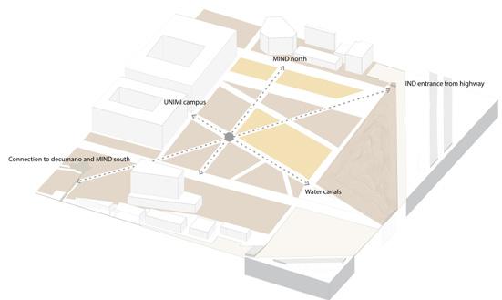
STRATEGY- ACCESS & CIRCULATION
FUNCTIONS
NGM MILAN E.N
WATER PIAZZA
URBAN LAKE TENNIS
RELAXATION AREAS
RELAXATION AREAS
RELAXATION AREAS
SMART TOTEM SMART TOTEM
NGM MILAN 35 SKATING RANGE
TENNIS COURT
WATER SPORT
SMART TOTEM
SMART TOTEM
SMART TOTEM
SMART TOTEM
NGM MILAN E.N 36
NGM MILAN 37
THE PROJECT ABOUT FUNCTION & CIRCULATION FLOOR PLANS & SECTION
NGM MILAN E.N 38
ABOUT
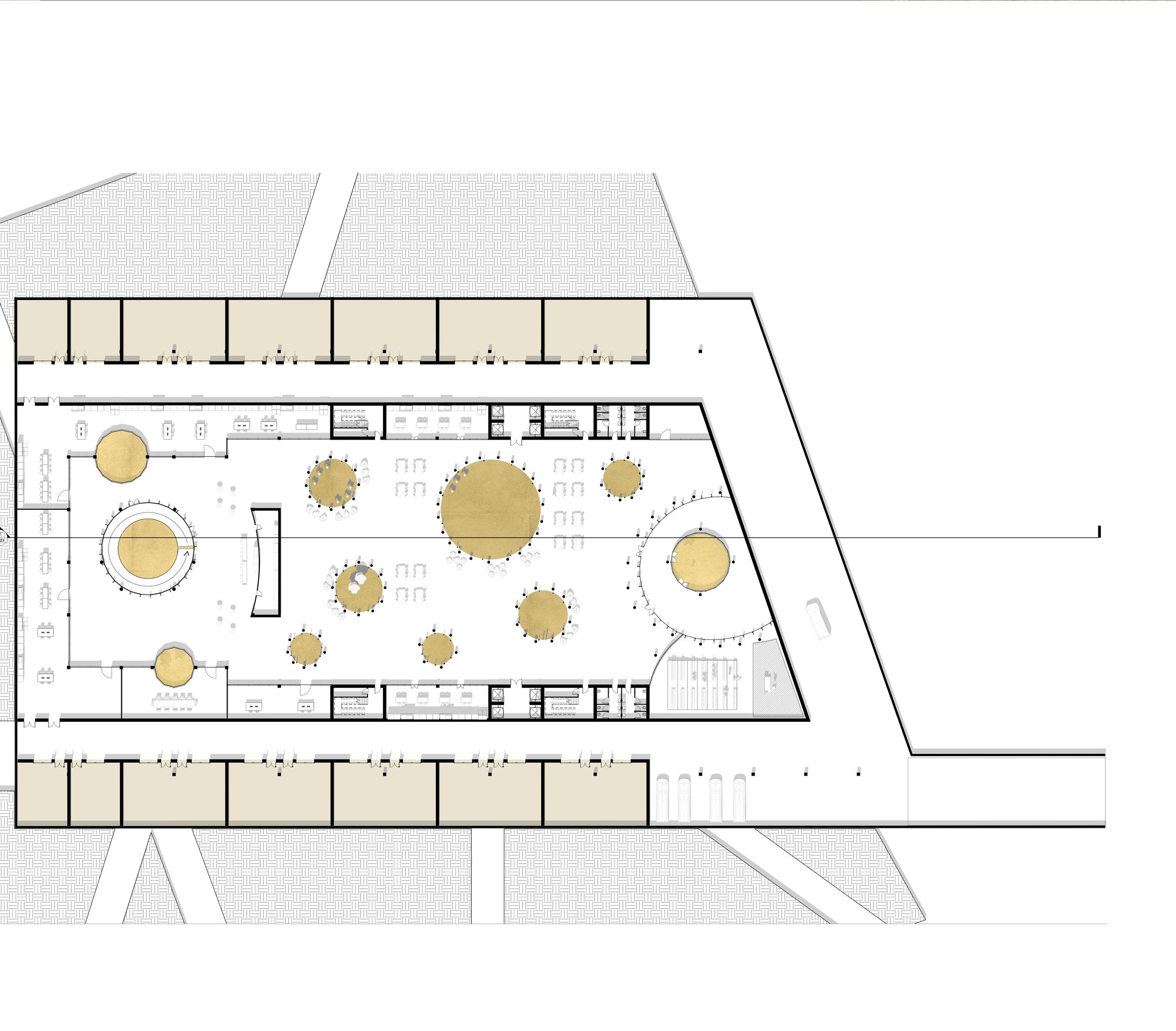
NGM is a mixed-programmed cultural development of 13,804 m2 with the primary purpose of exhibiting the most advanced architectural approach and research, with a focus on a made in Italy identity. Following MIND’s principles of science, knowledge, and innovation, the cultural centre offers research, an appealing focal point for visitors, and a sustainable solution by integrating its structure within the existing green fabric, expanding it, and generating new green urban areas.
The project, which was inspired by MIND’s common ground concept, features public urban spaces close to its two entrances from west to east. The building is oriented in a strategic location to connect the educational center to the park beside it, creating an urban quality that goes hand in hand with MIND’s concept of introducing a new way of walking within the city and a whole new perception of how green spaces are integrated within the public space.
THE PROJECT
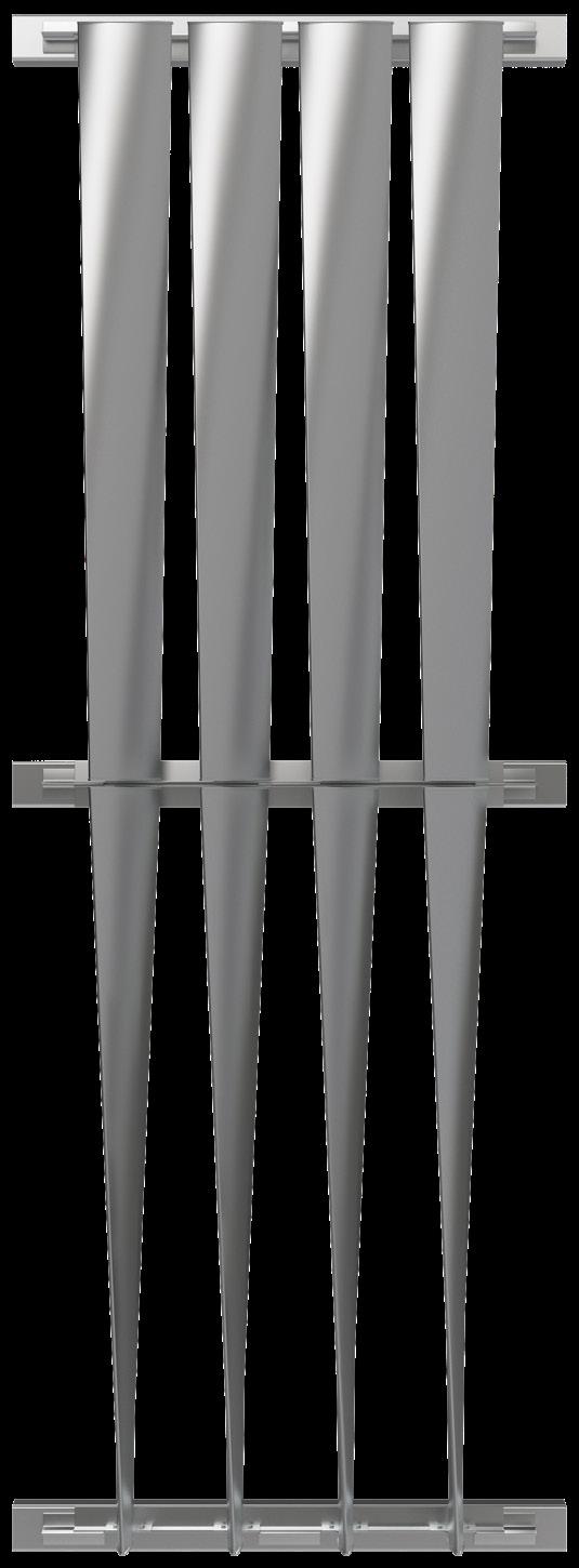
FORM
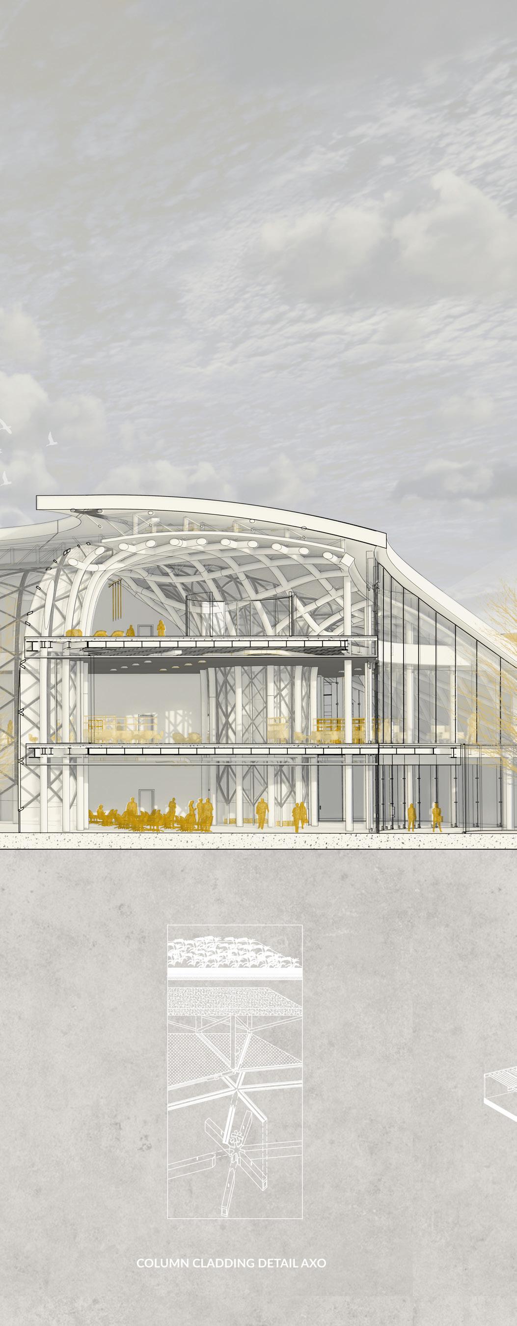
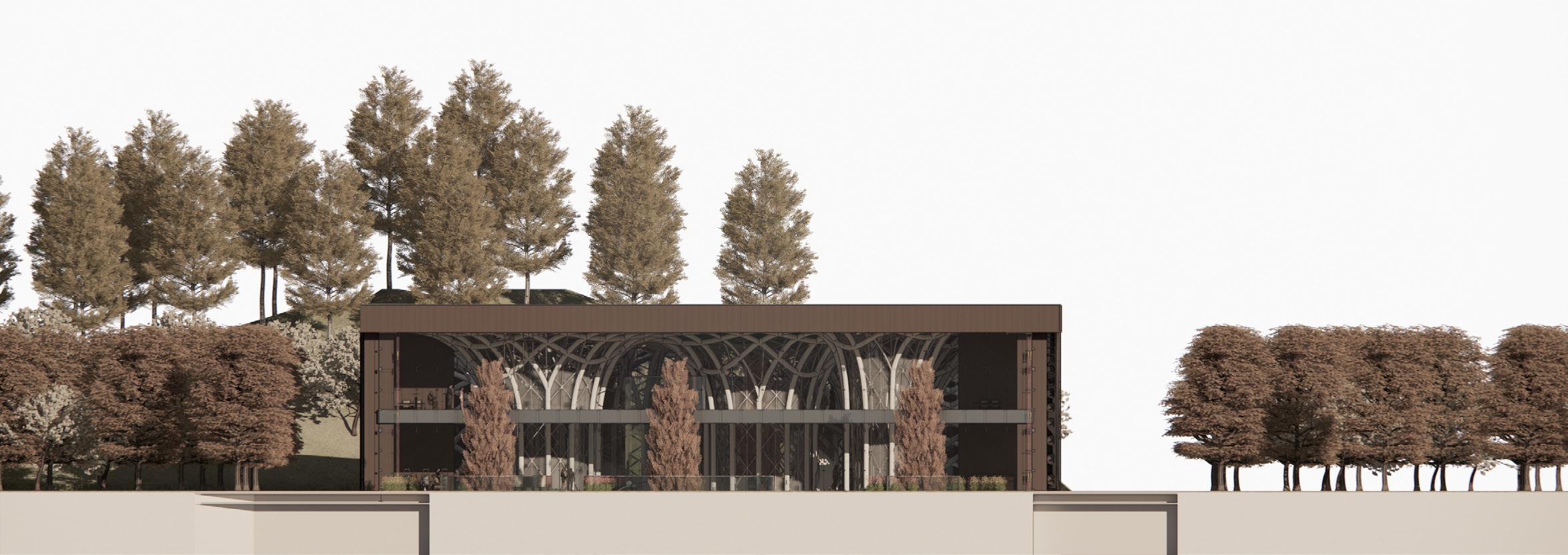
The structure is composed of four parts: a sequence of weaving structural tree-like columns, floor plates, an integrated facade that serves as the structure’s „skin,” and a green roof. It is designed as part of a green fabric, with columns that reflect the natural appearance of the flora around it.
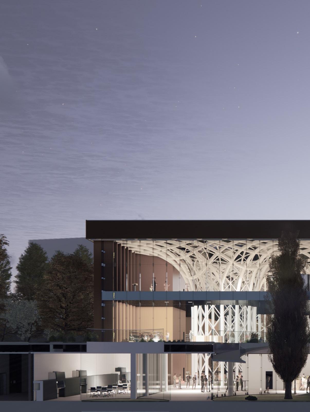
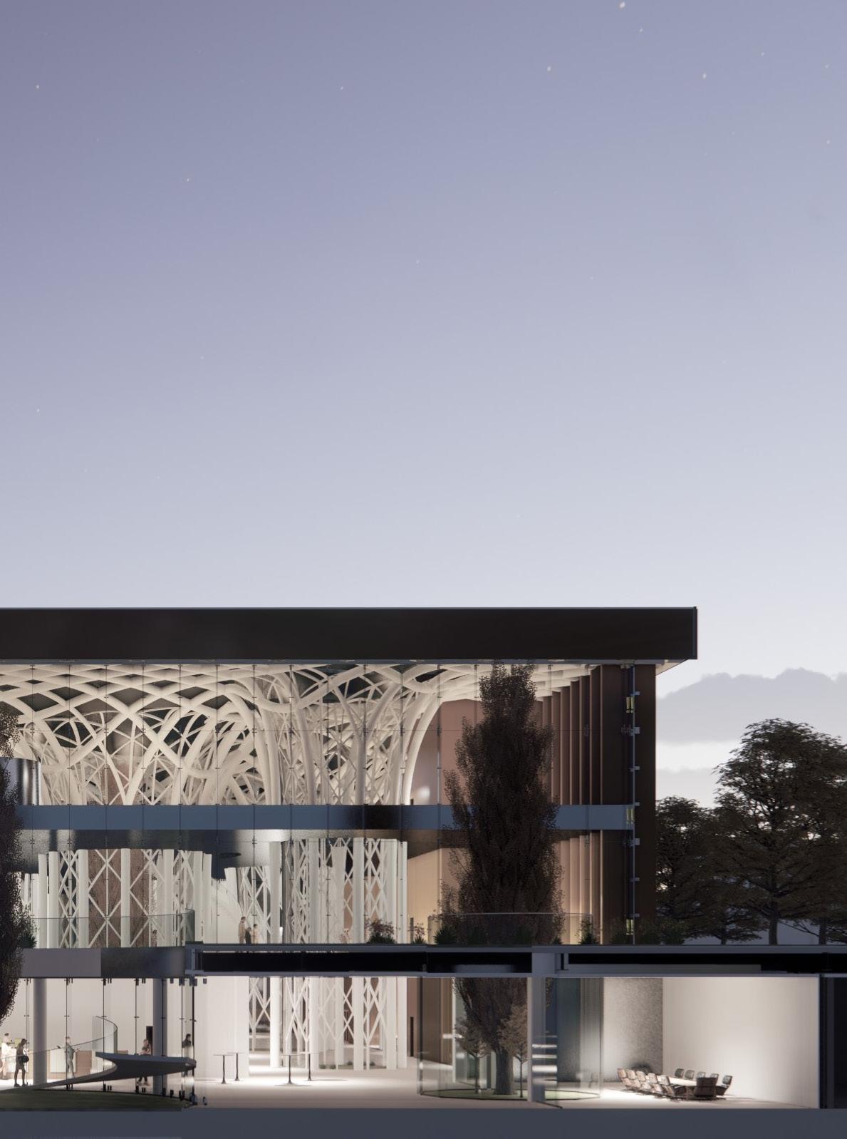
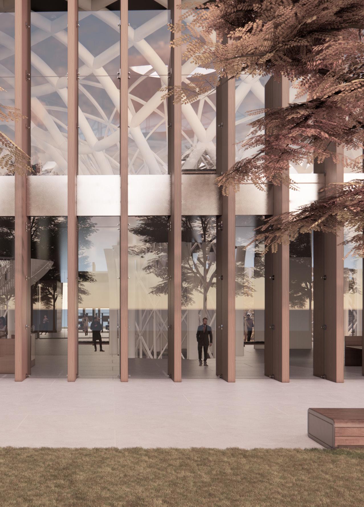
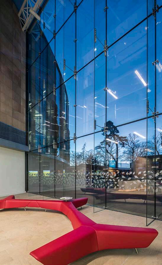
The east façade, as previously stated, faces the Mediterranean hill; the structural glass façade on that side offers transparency between indoor and outdoor, bringing nature into the building and letting those standing on top of the hill to see the steel construction inside.
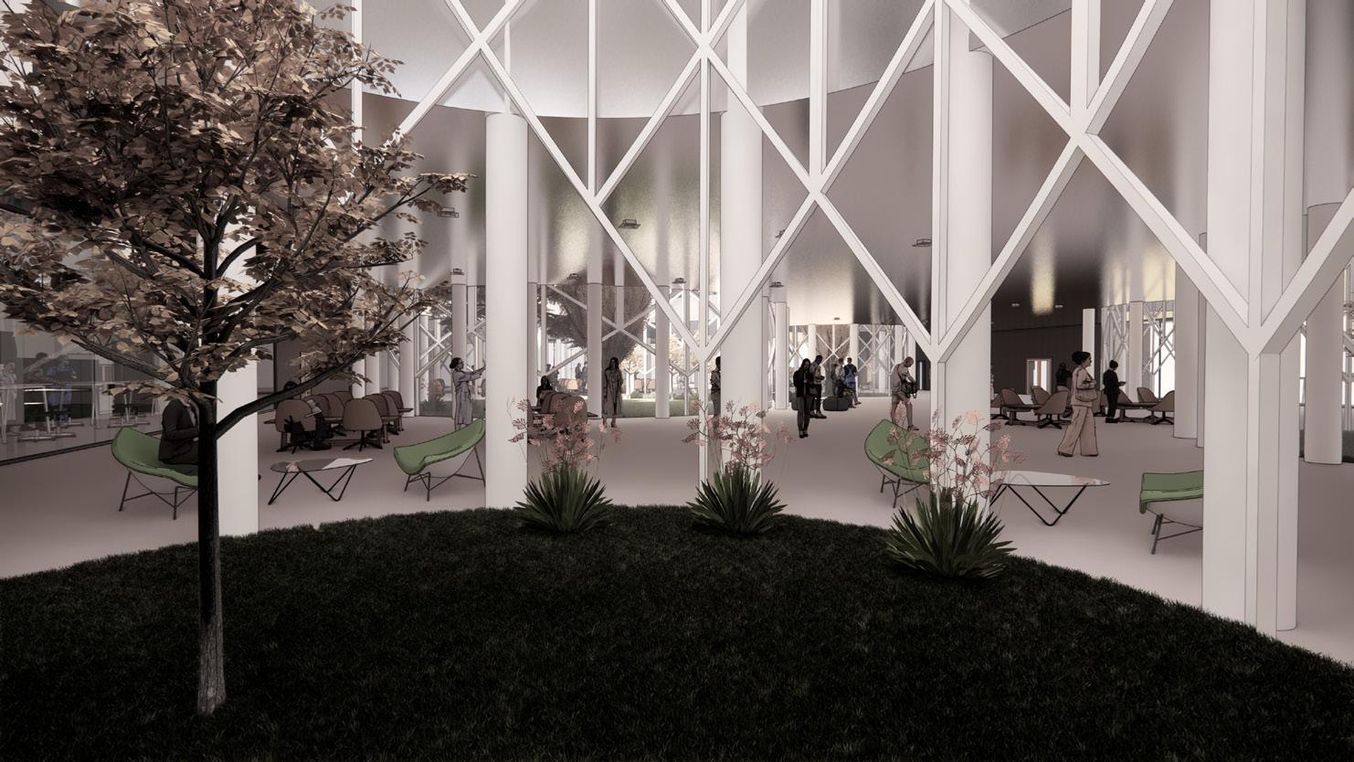
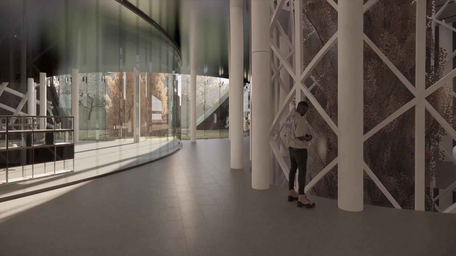
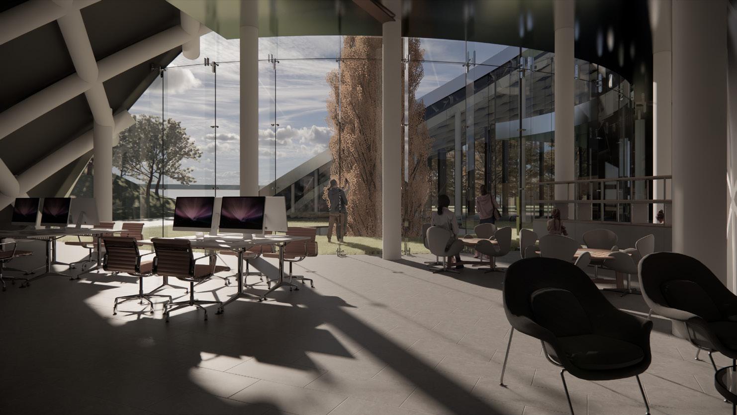
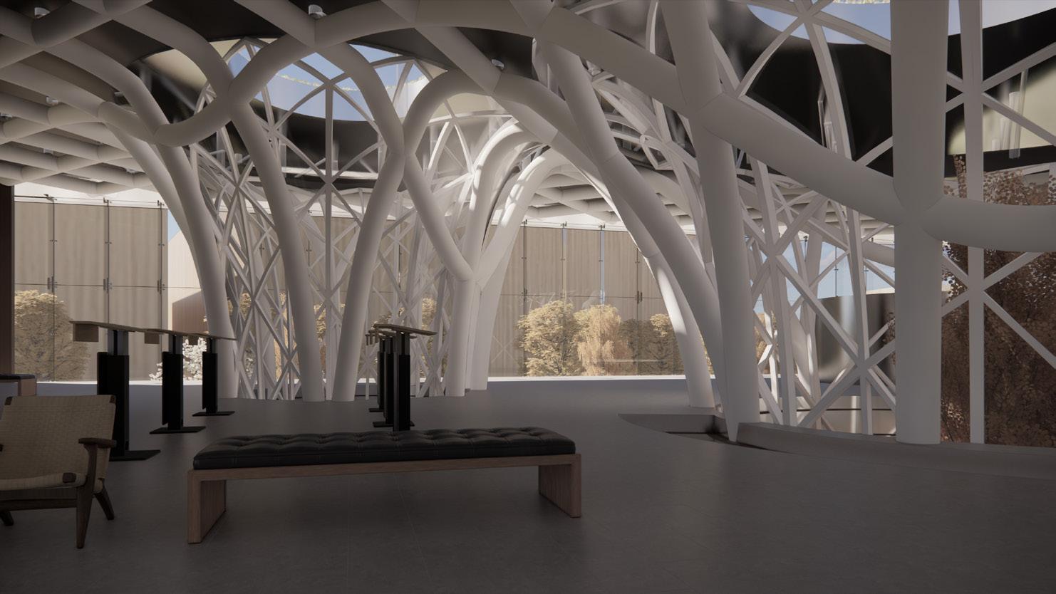
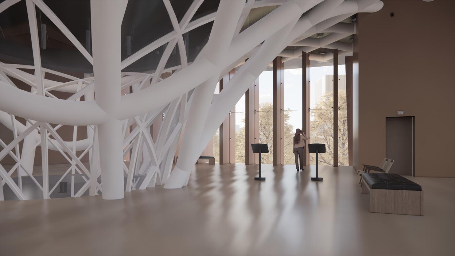
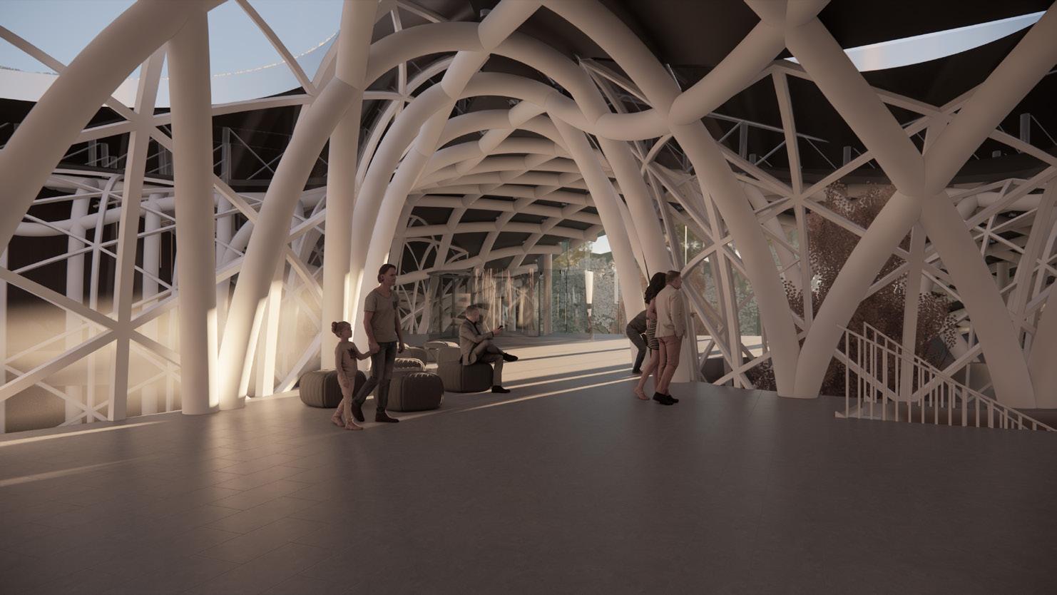
Another essential criterion was the concept of the inner courtyards which are created within the columns. Because of their scale, the columns can function as inner courtyards within the building, delivering light and ventilation to the interior. The various column widths and their asymmetrical distribution around the structure creat a distinctive shading effect and inspirational spaces around the floor plans, setting the tone of the circulation and atmosphere within the building.
CONCEPT
The concept of a building blended into the green fabric is largely inspired by MIND’s sustainability , energy and resource maximizing principles. In addition to the high environmental standard set for materials used in the project, the use of local materials predicts reduced carbon emissions.
As previously stated, the tree-like columns and skylight openings on top of them are the major elements that set the tone in the structure. They direct the building’s rhythm and the design of interior spaces. Their existence disrupts the normal floor plan nature and necessitates creative solutions in the planning of the building’s vital operations.
The diagrams below show the flow within the interior spaces with a non-traditional rhythm set by the columns.
NGM MILAN E.N 40
ABOUT Land Area Floor Area 3,948 m² 2,844 m²
THE PROJECT
&
Research center Circulation
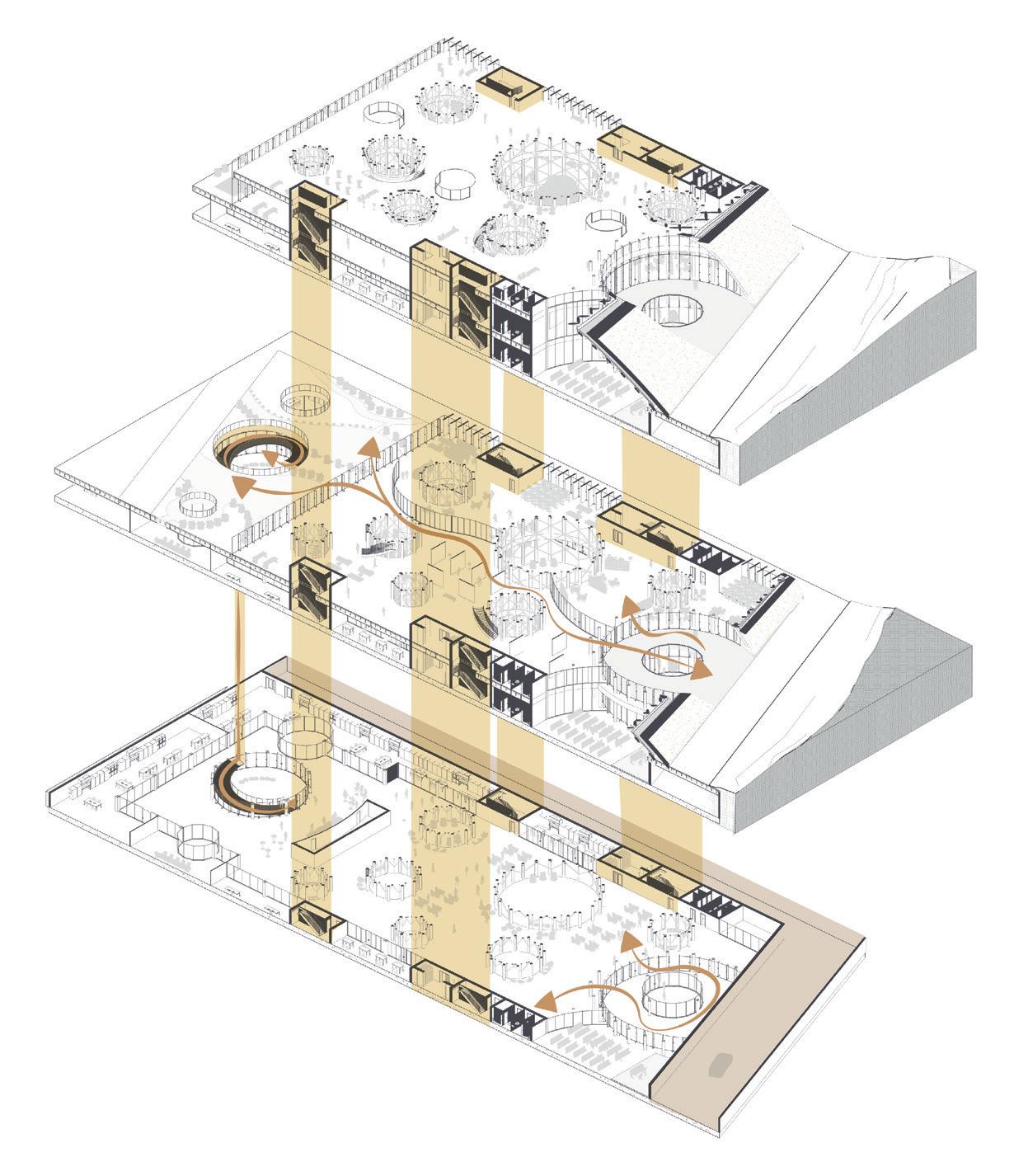
Exhibition/library Circulation Services and maneuver
Entrances and
NGM MILAN 41
exits Vertical Circulation
FUNCTION
CIRCULATION
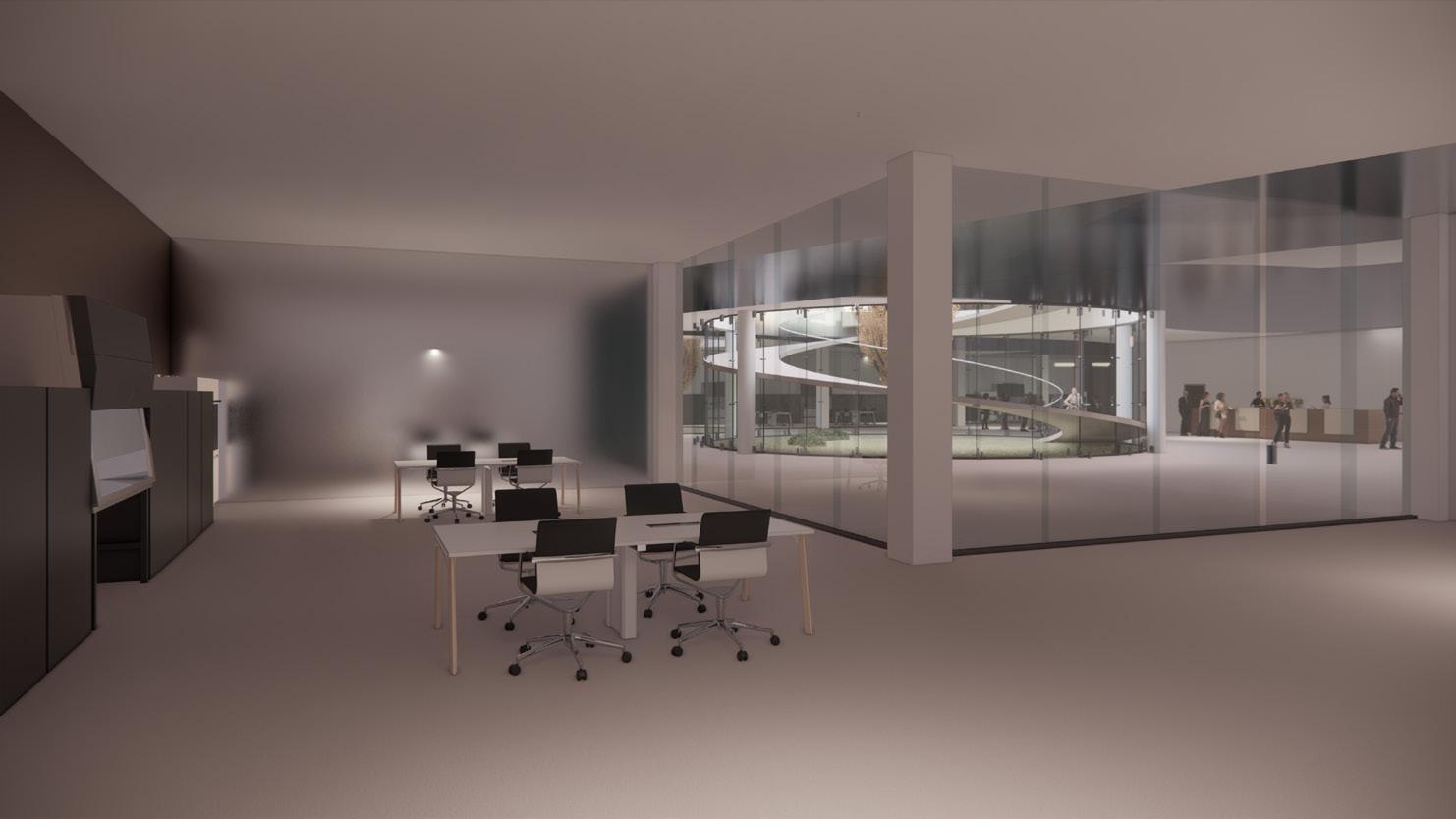
NGM MILAN E.N 42 THE PROJECT FLOOR PLANS AND SECTION Laboratory
view
Open work spaces
Perspective from the courtyards
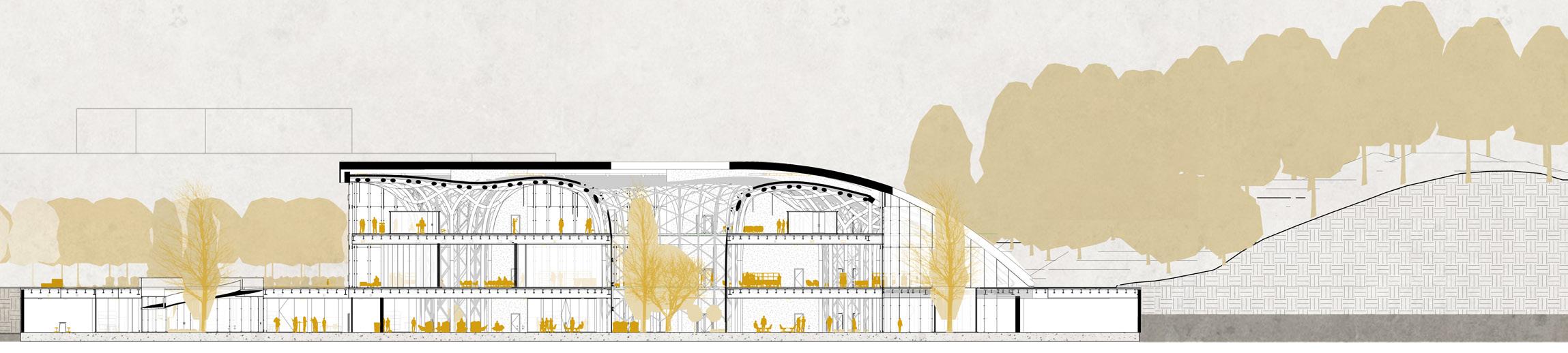

NGM MILAN 43 SECTION A-A’ 1:1000 Tecnical rooms and services UNDERGROUND PLAN 1:1000
NGM MILAN E.N 44
Hill side view
Main entrance view
Library hill view
NGM MILAN 45 SECTION A-A’ 1:1000 GROUND PLAN 1:1000
NGM MILAN E.N 46
Exhibition view
Emergency exit
Exhibition floor
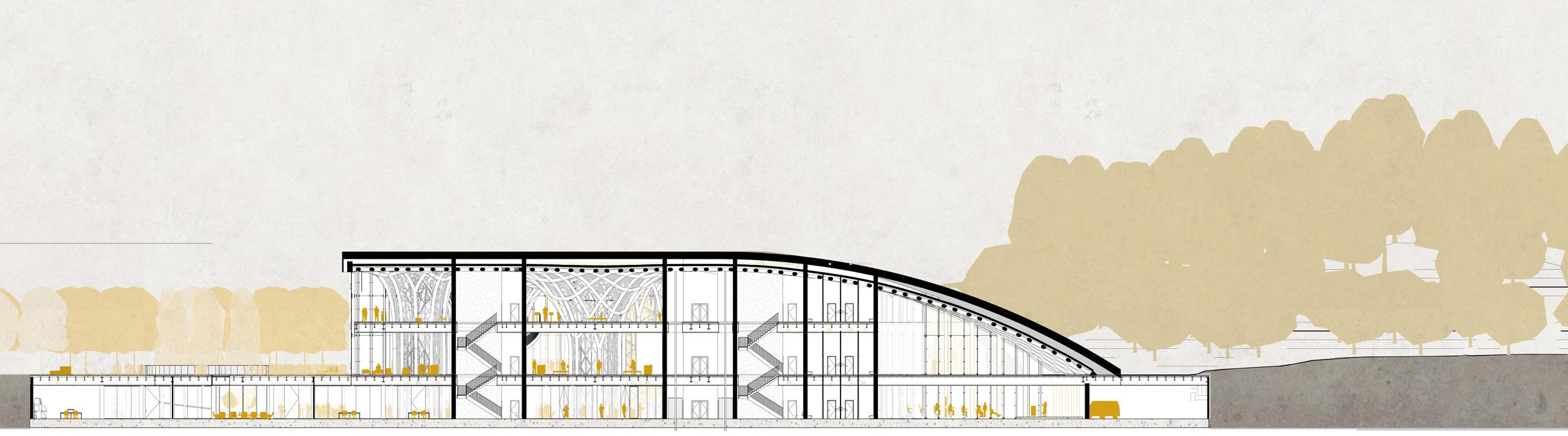
NGM MILAN 47 SECTION C-C’ 1:1000 FIRST FLOOR PLAN 1:1000 VR rooms
SUSTAINABLE MATERIALS
FACADE DESIGN
NGM MILAN E.N 48
ABOUT
SLAB
DESIGN
GREEN
ROOF COLUMNS CLADDING
NGM MILAN 49
ABOUT


One of MIND’s primary features, as previously stated, is sustainability. From its origins in the R-Expo display, the site’s goal has been to self-generate the energy that it consumes and to focus most of the design effort on consuming less energy and emitting less carbon. As a result, all developments in the district must meet a curtain sustainability level imposed by the overall concept.
In accordance with MIND’s sustainability criteria, all materials for the project were selected primarily from Milanese/Lombard enterprises, with consideration given to Co2 friendly modes of transportation to the site. In addition, each selected company lobbied for environmentally friendly products, which are outlined in this chapter
The design process in terms of materials is a delicate balancing act of architectural choices, longterm viability, and compatibility with the


project and its surroundings.
One of the primary issues in constructing the building’s envelope was solar gain, which will ultimately determine the energy consumption to keep the building at a comfortable temperature. Given the architectural notion of transparency, it was necessary to balance both design anchores. The solution consists of three façade types that are arranged in accordance with the light analysis. It enables the evaluation of the building’s facades that are most exposed to solar radiation, allowing the design to be properly changed.


The three types are: a completely glazed double-glass façade (structural glass), glazes with shading louvers, and timber opaque panels that allow controlling the rhythm of the façade and offering a sense of the internal arrangement.


Aside from the façade, another aspect of the building that contributes to energy
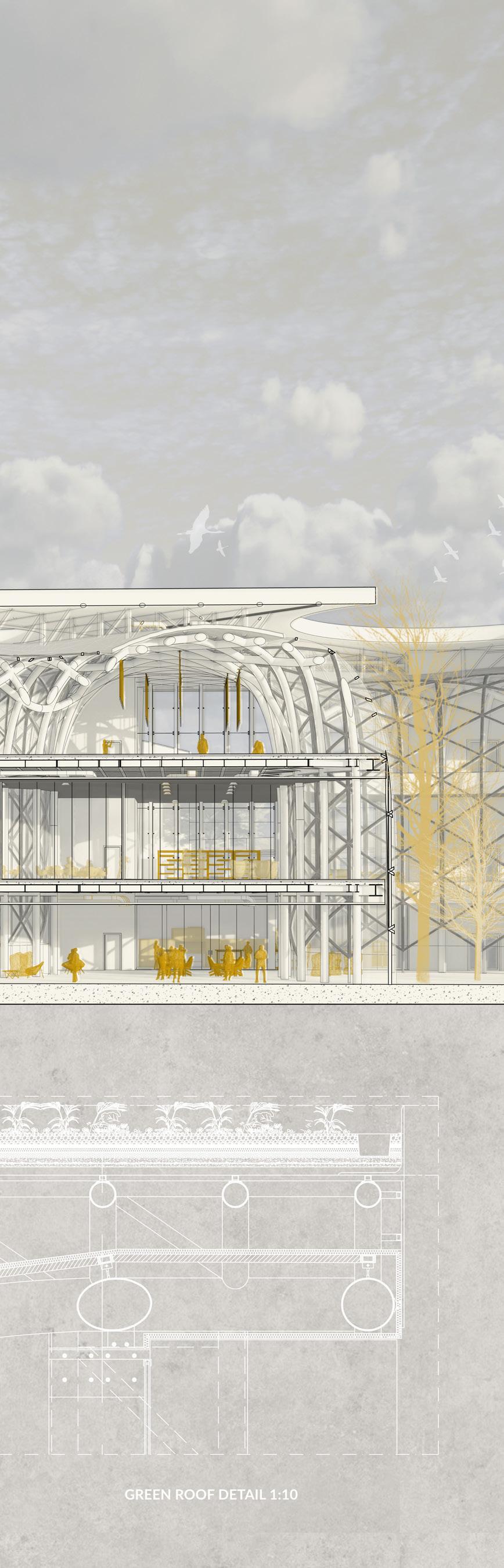
consumption is the material used for the roof. In this example, the solution presented was in line with both energy usage and concept, in the shape of a green roof (non-walkable to decrease structural loads) that provides a nice connection between the building and the park and contributes to the eco system.
NGM MILAN E.N 50
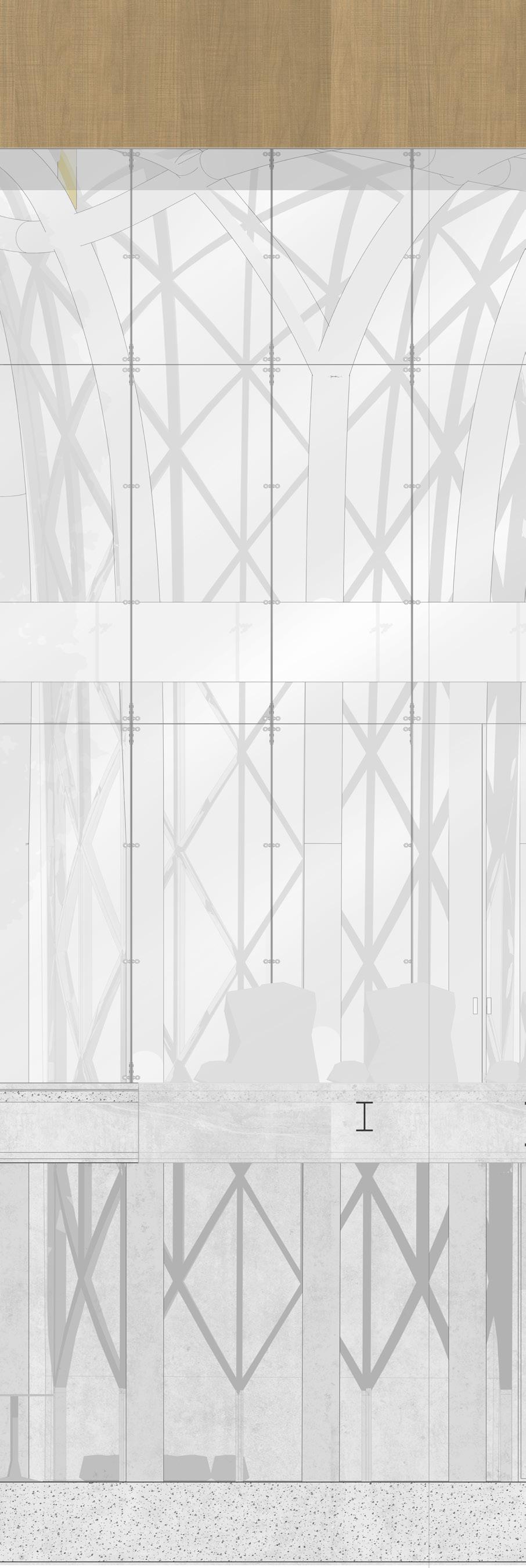
NGM MILAN 51 C Raft Foundation -7000 Excavation -7300 Roof Level L2 0 3 2 1 0 Raft Foundation -7000 Excavation -7300 Underground Level -5000 Groundfloor Level 0 1st Level +6000 Roof Level +13800 L3 0 W1 S1 S2 S2 S4 S2 S2 S4 W5 S1 T1 T2 HEB 550 IPE 500 IPE 500 IPE 330 A20 9 A19 9 A18 9 HEB 550 WEST FACADE- MAIN ENTRANCE Detail 1:100
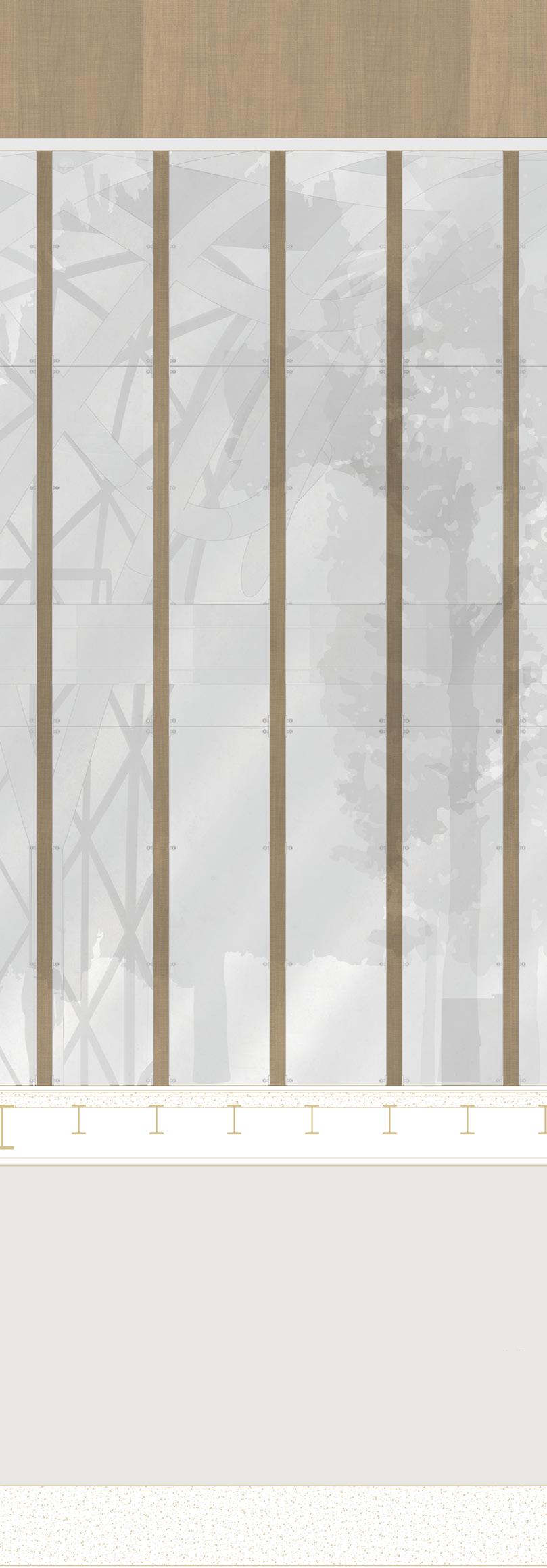
NGM MILAN E.N 52 3 2 1 0 I Raft Foundation -7000 Excavation -7300 Underground Level 5000 Groundfloor Level 0 Leve1st +6000 Roof Level +13800 W2 S1 S3 Curt.W1 S2 S2 S4 Louv1 HEB 550 IPE 500 IPE 500 IPE 330 T2 T1 A14 7 A13 7 A12 7 FACADE STRAIGHT LOUVERS Detail 1:100
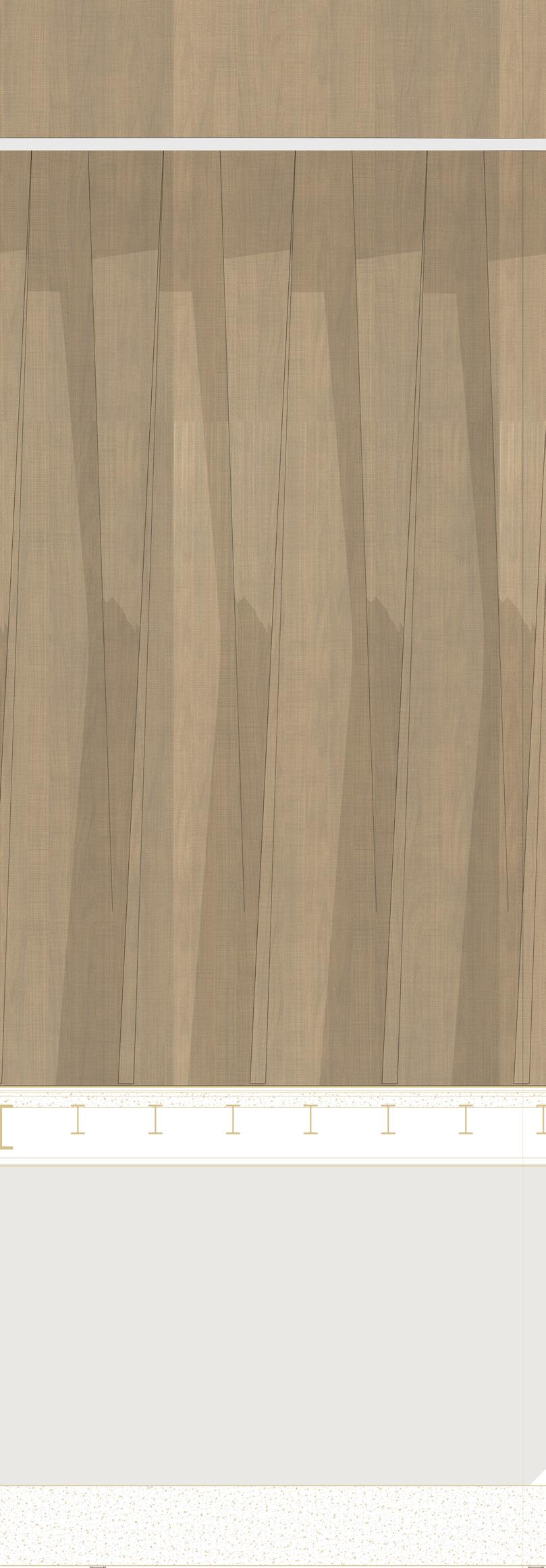
NGM MILAN 53 C 3 2 1 0 Raft Foundation -7000 Excavation -7300 Underground Level 5000 Groundfloor Level 0 Leve1s +6000 Roof Level +13800 W2 S1 S3 S2 S2 S4 W3 Louv2 IPE 330 IPE 500 IPE 500 T2 T1 A17 8 A3 4 A16 8 A15 8 FACADE TWISTED LOUVERS Detail 1:100
The
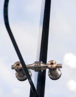
Pilkington Structural Glass System
Benefits : Load sharing
Specially developed fittings com bined with the much higher modulus of thestructural interlayer (compared with tra ditional inter layers) allows the System to share applied loads be tween both glass components of the laminate, giving a significant increase in load bearing capacity while at the same time reducing the thickness required.
Low deflection fully utilises the increased stiff ness of the interlayer (in some cases 100 times that of PVB) to reduce deflections under wind,
CS Wood grain powder coat
**Warm Walnut #011.
Construction Specialties:
CS Wood Grain Powder Coat
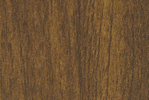
Finish is durable, with superior scratch and fade resistance. It offers the realistic look of wood without destruction of trees or the costly, time consuming main tenance required with real wood. In addition it will not deteriorate due to weather. It is an earth friendly product that can stand up to all types of weather condi
**This finish is suitable for all CS Grilles and Sun Con
NGM MILAN 54
Structural glass system
Pilkington Planar™ Support Structures
Glass Fin (Mullion) Systems
use of Pilkington Planar in combination with a glass fin system creates the ultimate in transparency. Glass fins are used to transfer wind loading to the structure. Pilkington Architectural have led the way in the development and testing of this design technology. Structures of this type can be either supported at the base (ground based) or suspended (hung) from above depending upon the height of the façade. The weight of both the panels and the fins is carried by the connection at the head or base of each fin. Stonehenge Visitor Centre – Wiltshire. Images Courtesy of Vitrine Systems Ltd. Glass Fin (Mullion) Systems processes permit. Final color selection should be from actual finished color chips. The super durable textured finish comes
Douglas
Fir #003 Lyptus #004 Warm Knotty Pine #005 Black Cherry #009 Light Walnut #010 Warm Walnut #011
Barnwood
#016 American Oak #017 Pacific Coast Fir #018 Scrubbed Walnut #020 Oxidized Bronze #021 SOLUTIONS COLOR CARD
HP is tested on steel structures according EN 13381-
on concrete/profiled sheet steel composite member accord
13381-5,
of them in
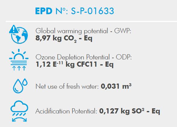
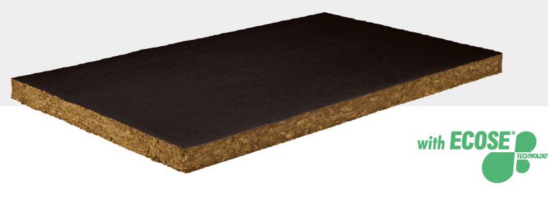
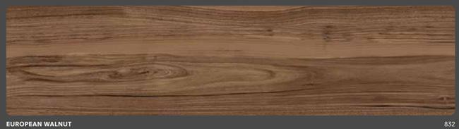
NGM MILAN 55 Fixed twisted louvers Construction Specialties, Italy Features ◊ Design flexibility ◊ Promotes lower energy use ◊ Increases safety and security Benefits ◊ Blades can be in sequential or irregular order to express ◊ your design aesthetic ◊ Lessens glare and solar heat gain yet allows filtered light in Applications ◊ Decorative facades ◊ Parking facilities Aluminum composite panel COMPOSITES Finish- Wood grain powder coat, European Walnut 832-3A Rock Mineral Wool panels Knauf Insulation benefits: ◊ Indoor Air Quality thanks to ECOSE Technology® ◊ Non-combustible (Euroclass A1) ◊ Excellent thermal insulation (λD 0.034 W / mK) ◊ Black glass veil coating Environmental impact indicators: **Perlifoc
4 and
ing EN
all
accredited laboratories. ©2020 Construction Specialties, Inc. |c-sgroup.com PS.TWSS.1120 design enthusiasts looking response to the architectural we have created a twisted achieved by mounting blades on innovative approach by creating a Material Properties Standards Units Linear Thermal Expansion EN 1999 1 1 2,4 mm / m at 100 C temperature difference Tensile Strength of Aluminum EN 485 2 Rm >130 (N/mm^2) Core Mineral filled polymer Surface Lacquering Gloss (initial value) Pencil Hardness EN 13523 2 EN 13523 4 Acoustical Properties Sound Absorption Factor Sound (as) Transmission Rw ISO 354 ASTM E90 0.05 OITC: 24 Thermal Properties Thermal Resistance Temperature Resistance ASTM C518 0.009 [m K/W] 50 to +80 Fire classification acc. to EN 13501 1 Class B s1,d0 Twisted louvers, Construction Specialties
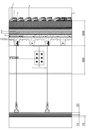
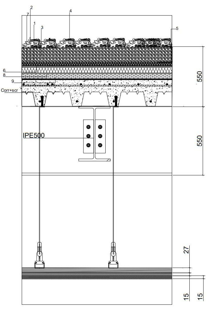
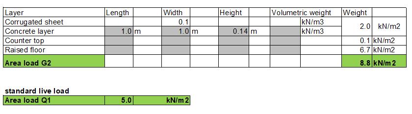
SLAB LAYERS
1 Corrugated sheet with concrete screed -cls- SANRDINI METALLI, thickness 140 mm.
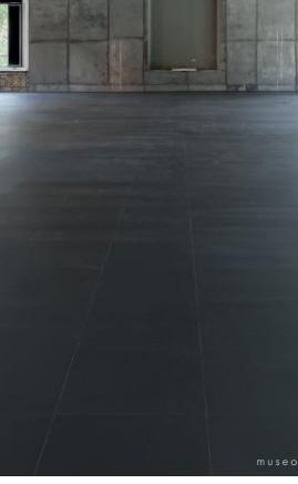
2 Raised floor 4.0 by NESITE, A completely customizable raised floor finished with a pigmented heterogeneous resin,which, after drying, forms an anti-scratch and shock-resistant film, which makes it suitable for mediu traffic. Grey whale color. Thikness 250 mm. 100% Recyclable
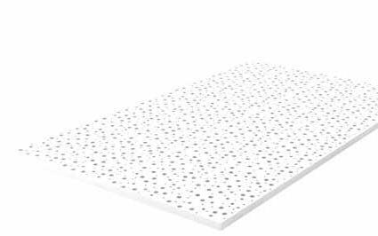
3 Countertop by GYPROC -Rig itone® Activ’Air®8-15-20 Super v- metallic structure Gyprofile with organic chromium-free, eco logical, anticorrosive, dielectric, antifingerprint coating, com posed of C 27/48 metal profiles in 0,6 mm Z100 galvanized steel sheet. Thikness 57 mm.
NGM MILAN E.N 56 1 2 27 15 15 IPE500 550 270 HEB550 3
SLAB DETAIL 1-50
Rigitone
colours
FLOOR
finishes.
color range is available in 2 versions, PLAIN (homogeneous effect) and CONCRETE.
formaldehyde-free panel (class EN 717-1) with a low volatile content varnish.
the production process are used only 100% separately recyclable components.
to obtain the LEED certification.
SHEET
Environmental Product Declaration
the International EPD® System. The EPD
■
■
been developed
General
Instructions
accordance with ISO 14025,
Activ'Air
Dimensioni
Prodotto
TOP
Qualità dell’aria
prodotto contiene l’esclusivo sistema Activ’Air®, che permette di assorbire e ridurre fino al
della formaldeide
nell’aria dell’ambiente
classificato
l’air intérieur», riguardante
NGM MILAN 57 ◊ versatility of
and
◊ the
◊
◊ in
◊ contributes
MILK CONCRETE WHITE 9003 GREY WHALE NESITE COLLECTION SILVER GREY 7044 AGATE GREY 7038 STONE GREY 7030 COURROGATED
4.0
COUNTER
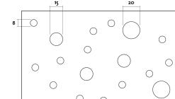
◊ Rigitone® Activ’Air® 8-15-20 Super -Perforat ed coated gypsum board with 4 straight edges ◊ Irregular round drilling, with offset holes ◊ Acoustic fabric applied on the back Rigitone ® Activ'Air ® 8-15-20 Super LASTREIl prodotto deve essere decorato in opera, dopo la finitura (riempimento) dei giunti. Tipo bordo 4 bordi diritti Bordo (dimensioni in mm) Rotonda irregolare sfalsata (mm) 1200x1960 12,5 9,3
®
8-15-20 Super ■ Lastra di gesso rivestito forata con 4 bordi diritti ■ Foratura rotonda irregolare, con fori sfalsati ■ Tessuto acustico applicato sul retro ■ Installazione su struttura Gyprofile, per una perfetta planarità del controsoffitto Assorbimento acustico Ambiente, sanità, riciclo ■ I prodotti Rigitone® possiedono la Dichiarazione Ambientale di Prodotto (EPD, vedi pag. 8), verificata da un ente terzo indipendente. ■ I prodotti sono caratterizzati da basso impatto ambientale, come previsto dall’approccio Gypsum Forever. ■ Sono prodotti naturali, costituiti in massima 1960 12,5 Dimensioni in mm Superficie forata: 10% Has an
in
has
in
the
Programme
MATERIAL STRATIGRAPHY Rigitone ® Activ'Air ® 8-15-20 Super LASTRE Reazione al fuoco Euroclasse A2-s1,d0 secondo norma EN 13501-1. Finitura Il prodotto deve essere decorato in opera, dopo la finitura (riempimento) dei giunti. Installazione Per le modalità di installazione delle lastre Rigitone® Activ’Air® vedere le pagine da 254 a 257. Tipo bordo 4 bordi diritti Bordo (dimensioni in mm) Tipo di foratura Rotonda irregolare sfalsata Dimensioni (mm) 1200x1960 Spessore (mm) 12,5 Peso (kg/m2) 9,3 Rigitone® Activ'Air® 8-15-20 Super ■ Lastra di gesso rivestito forata con 4 bordi diritti ■ Foratura rotonda irregolare, con fori sfalsati ■ Tessuto acustico applicato sul retro ■ Installazione su struttura Gyprofile, per una perfetta planarità del controsoffitto Assorbimento acustico Ambiente, sanità, riciclo ■ I prodotti Rigitone® possiedono la Dichiarazione Ambientale di
(EPD, vedi pag. 8), verificata da un ente terzo indipendente. ■ I prodotti sono caratterizzati da basso impatto ambientale, come previsto dall’approccio Gypsum Forever.
Sono prodotti naturali, costituiti in massima parte da materiali riciclati, che non spolverano e sono privi di fibre o sostanze pericolose per la salute. 1960 12,5
interna Il
70%
presente
interno.
Il prodotto è
A+ secondo la norma francese «Émissions dans
l’emissione di COV.
in mm Superficie forata: 10%
SLAB LAYERS
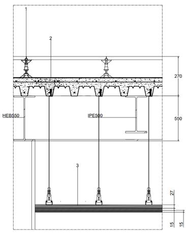
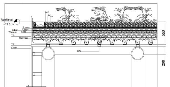
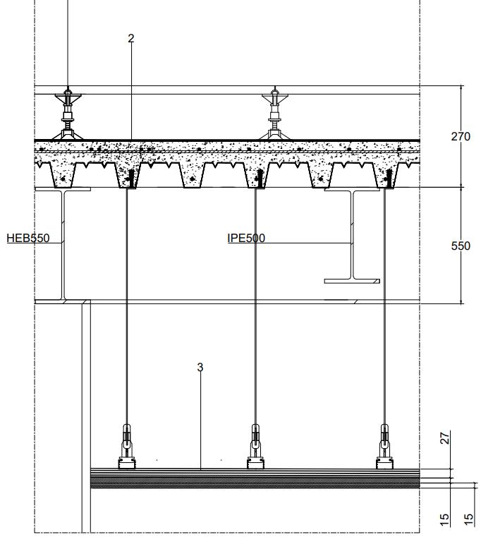
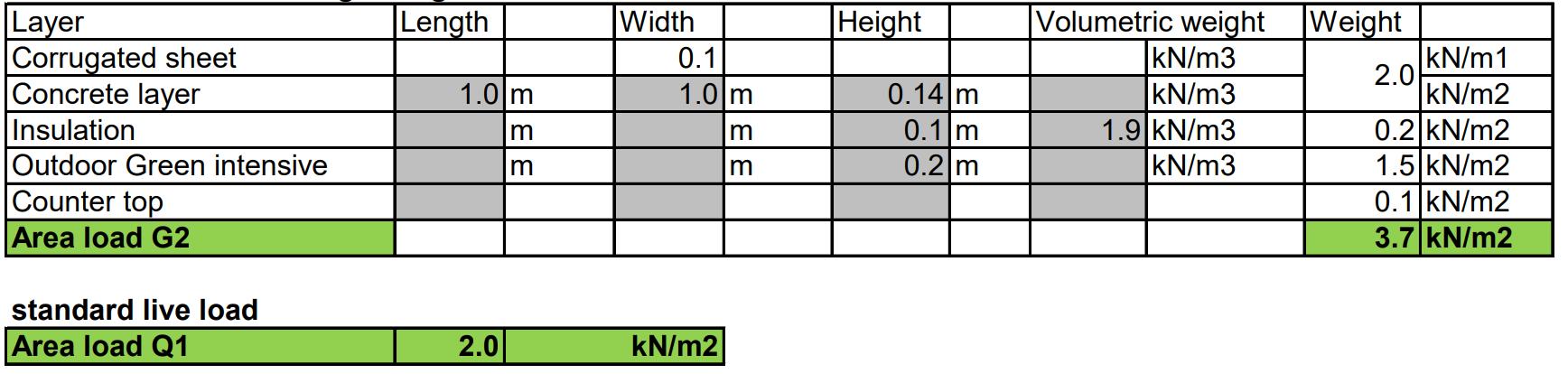
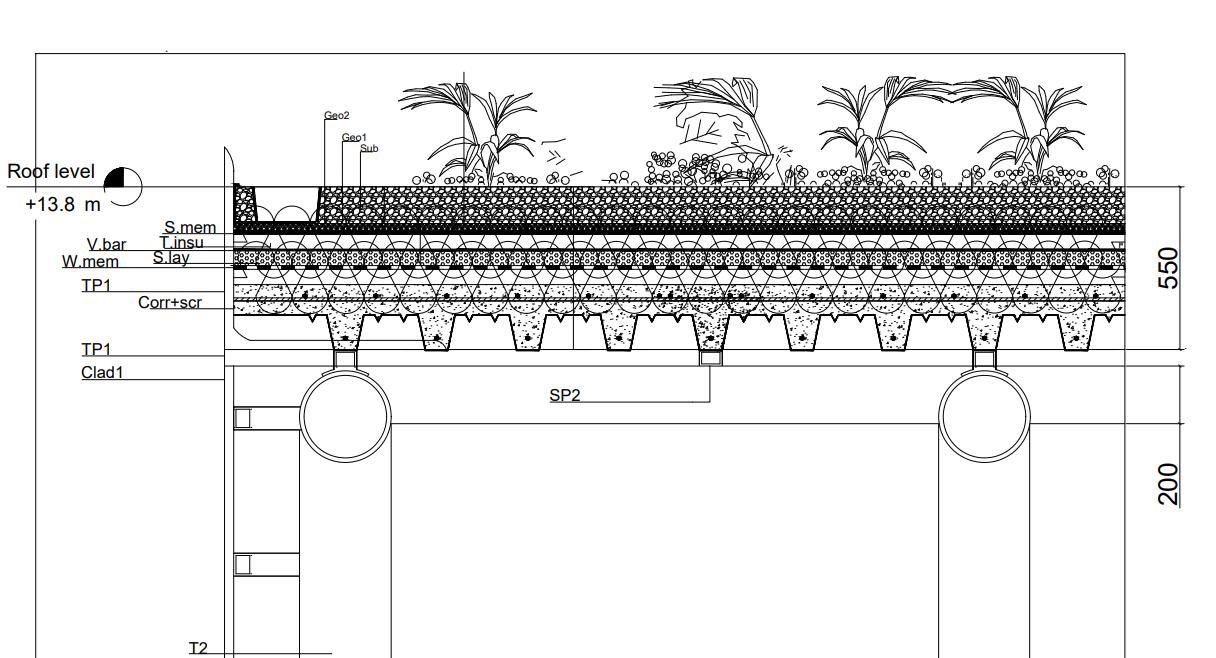
GREEN ROOF SYSTEM (FERTIL)
1 Needle-punched and heat-set non-woven geotextile (GTX-N)
FERTILROOF Stratum 500 to protect the element sealing and protec from the action of the roots. Thickness 3.0 mm. Weight 500 g / m2.
2 Draining geocomposite, con sisting of geomat coupled with non-woven geotextile, 20 mm thick.
3 Cultivation substrate LightTer Extensive type, with prevalent mineral composition, complying with the requirements of the UNI11235: 2015 standard.
4 Vegetation in Sedum spp.Se dum acre(herbaceous essences).
5 Perforated L-shaped shingle metal profile in Aluminum, 1.5
mm thick, for separation from the bands of ballasting and pe rimeter drainage, with dual direc tion of installation (h 8,0 - 10,0 cm).Musola Metalli S.p.a.
6 Single-layer synthetic mem brane made of homogeneous PVC-P obtained by coextrusion. (1,50 mm).SOPREMA ITALIA
7 Thermo insulating element: Self-extinguishing sintered ex panded polystyrene. 30 mm thick. COPERNIT S.p.A.
8 Vapor barrier layer in water proof class W1 (resistance to a water column pressure of 20 cm for a duration of 2 hours) in accordance with the provisions of UNI EN 13984 and UNI EN 13859-1, with guaranteed even after the UV / IR aging tests required by UNI EN 1296
NGM MILAN E.N 58
1 3 5 6 7 Corr+scr 550 IPE500550 27 15 15 4 2 8 9 SLAB DETAIL 1-50 220Scr Connecting Oticplacode Pav TP1 Clad1 T1 550 200 400 Geo1 Sub Geo2 S.mem T.insuV.bar S.lay Corr+scr W.mem T2 TP1 SP2 300 200 1 2 3 4 5 6 A B C D E F G First floor +6.00 Roof level Ground floor +13.7 Roof level +13.8 m First floor +6.00 m A12 10GREEN ROOF DETAIL 1-50
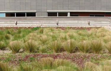
EXTENSIVE SYSTEMS
Extensive systems are roofs built mainly with an ecological func tion in mind, to improve living comfort, and are rarely usable spaces. Nowadays, they often host a solar, thermal or electro voltaic system which improves efficiency.
Extensive systems are built with prostrate or creeping plants, suit able for growing in thin layers of substrate.
The load on the building is re duced and suitable for almost all building types.Maintenance is reduced and irrigation is optional (to be evaluated in particular cli mate zones).
NGM MILAN 59 TYPE OF GREENING Semi intensive with turf. Intensive with perennials, trees and shrubs. STRUCTURAL STRENGTH OF THE BUILDING 250 350 kg m2 RUNOFF COEFFICIENT 0,3 0,5 NOTES High ecological interest with abundance of species. Possible fruition
Raft Foundation -7000 Excavation -7300 Underground Level -5000 oorGroundf Level 0 Level1st +6000 Roof Level +13800 3 2 1 0 T1 S1 S5 S2 S2 T1 IPE 500 HEB 550 T2 S4 Cod. Technical Elem.M aterial Dim. TP1 Tubular profile 100x100 mmsteel Gla.p double glazed glass Af1 T=50 mm aluminum Glass panel Aluminum frame 1 T=120 mm SF2 steel T=20 mmSteel frame 2 SF1 steel T=160 mmSteel frame 1 T2 steelTube 2, secondary structure R=20 cm C.Alu ACPComposite Aluminum Panel T=50 mm NGM MILAN 61 COLUMN CLADDING DETAIL 1:100
DEATIL SECTION Detail 1:20 3 1 20 16 95 120 500 335 86 8016 44 32 140 229 Sub Geo1 Geo2 TP1 S.mem T.Insu V.bar Corr+scr W.mem S.lay Sp2 Sp1 Pav1 RF Corr+scr 250 168 1100 T2 200 800 200 650 300 550 IPE 500 IPE 500 HEB 550 T1 T1 C.Alu Gla.p Af1 NGM MILAN E.N 62
Cod. Technical Elem.M aterial Dim.s TP1 Tubular profile 100x100 mmsteel Gla.p double glazed glass Af1 T=50 mm aluminum Glass panel Aluminum frame 1 T=120 mm SF2 steel T=20 mmSteel frame 2 SF1 steel T=160 mmSteel frame 1 T2 steelTube 2, secondary structure R=20 cm C.Alu ACPComposite Aluminum Panel T=50 mm COLUMN CLADDING DETAIL 120 160SF1 SF2 T2 C.Alu Corr+scr NGM MILAN 63
STRUCTURAL DESIGN
LOAD
design Continuous beam design Column design
NGM MILAN E.N 64
INTRODUCTION STRUCTURAL DRAWINGS STRUCTURAL
CALCULATIONS Slab
SPECIAL STRUCTURAL SYSTEM CASE STUDY
INTRODUCTION
The project’s concepts Is demon strating how the architectural and structural systems integrate, reaching the final result of spaces which are not only visually intri guing but also using new tech nologies to enhance structural performances. Throughout the process of the design, The struc tural development and the archi tecture go hand in hand, chan ging and developing according to both structural and architectural needs.
New Gate Milano is a mixed -program which combines Lib rary, Museum, Exhibitions, and Laboratories. It is designed for in specific area in MIND innovation district in city of Milano in Italy.
The building is approximately 13,804 m² ,Which in three levels of facility provides a wide range of services such as experience are as including VR technology, Free movement museum, a book-len ding library, laboratories(open to public), an Amphitheater, indoor and outdoor gardens, and coffee shops.
All 3 platform (one of which is underground) are supported by big scale columns systems which have 3 functions: structural sup port, ventilation, and light pe netration into the building. The challenge we faced throughout the structural design was to allow the main structural support to be the anchor points, creating as much free space as we could on the upper floors were the exhi bition and library are located.
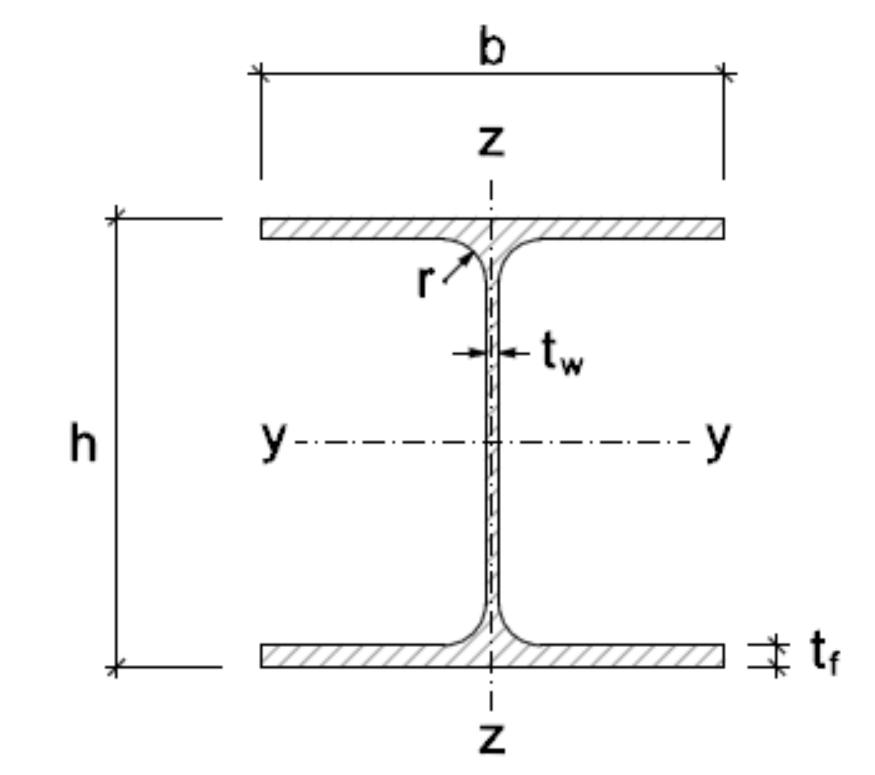
TYPICAL DIMENSIONS
The boundary of the building is a trapezoid with lengths of 104/48m and with approxima tely 3686 sqm foot print.
Each level floor area is as follows: 1- Underground: 7256 m² 2- Ground level: 3642 m² 3- First floor: 2906 m²
The building has three types of structural systems integrated with each other. The main one is The truss/tree columns (anchor points) integrated with the roof’s
structure. The second is the combination of a honey comb slab structure and regular beams structure of the slabs. the third one is more of a regular struc tural system which is located underground and in the external laboratories part.
All of these different structural systems are divided by grids of 8 meter. The height of each flo or considering the slab thickness is 6m(the ground floor’s height is 5m) . Thus the total height of the building is 12m above ground.
HOW DOES THE STRUCTURE WORK?
The truss/tree column bear the load of all slabs and roof by using a system of arches. Thus, in some parts of the structure the arched shape of the single elements gi ves a hand to the load bearing system. Almost all the back part of the building is self supported thanks to the arched shaped of the structure in this area.
NGM MILAN 65
NGM MILAN E.N 66 STRUCTURAL DRAWINGS Steel pipes 400 mm R Framing system IPE500 Shear walls 400 mm Underground steal columns HEA500/300
Snd
B C D E F G H I J 21 3 4 5 6 7 8 9 10 Pav2 Scr2 Pop Sct V.Cl Cod. Technical Pavement Screed Extruded panel Isocal screed systems Ventilated cavity Finishing foundation Fsl Waterproofing membrane W.mem Snd Sand Hc Hard WallW1 Insu Insulation 0 202 100 1000 390 160 160 85 20 165 200 200 200 200 200 200 30050 50 W2 W2 200 200 200 200 300 50 50 200 0 400 0 Raft Foundation -7000 Underground Level -5000 Raft Foundation -7000 Underground Level -5000 200 200 200 200 200 200 200 90 200 200 200 200 200 90 90 90 1000 50 50 Pav2 Scr2 Pop Sct Fsl V.Cl Rft.F Rft.F W2 Rft.F Raft Hc Snd W.mem A3 4 A4 4 A5 4 Pav2 Scr2 Pop Sct V.Cl Cod. Technical Elem.M aterial Elem Cod. Dimensions Pavement Screed Extruded polysterene panel Isocal formworks screed with transit for systems cavity with Iglu’® Plus Finishing slab Ceramic Concrete Polysterene Concrete Reinforced Concrete C25 W=12 cm W=6 cm W=10 cm W=8 cm W=27 cm W=5 cmFsl membrane W= negligibleW.mem
Sand layer Sand W=10 cm Hc Hard core layer Concrete W=20 cm Wall 1, retaining wall W= 40 cm, H=5 m W1 W=10 cmInsu Reinforced Concrete C25 H=1 mC25Reinforced Concrete NGM MILAN 67 UNDERGROUND COLUMNS FOUNDATION 1:50
21 3 4 5 6 7 8 9 10 A B C D E F G H I J 21 3 4 5 6 7 8 9 10 20 Raft Foundation -7000 Excavation -7300 Underground Level -5000 Raft Foundation -7000 Excavation -7300 Underground Level -5000 A6 5 A7 5 A8 5 A9 5 20 2 0 0 200 100 1000 90 90 200 200 1604 160 85 20 110 45 1560 800 T1 Sct 200 100 1000 90 90 200 200 390 160 160 85 20 Pav2 Scr2 Pop Sct V.Cl Cod. Pav2 Scr2 V.Cl Snd Hc Sct V.Cl Snd Hc Pop Pop Pav2 Scr2 C1 C1 Pl.C T1 Pl.T 800 W.memW.mem Fsl W.mem Snd Hc Sub Geo1 T.insu Geo2 V.bar S.lay Sub Geo1 Geo2 T.insu S.lay Pl.T T1 Pl.C C1 1100 1100 110 110 2 1100 110 Pl.T Pl.C 715 715 Fsl Fsl165 230 250 230 390 165 230 250 230 Rft.F Rft.FRft.F PARAMITRIC COLUMNS FOUNDATION1:50 NGM MILAN E.N 68
21 3 4 5 6 7 8 9 10 A B C D E F G H I J 21 3 4 5 6 7 8 9 10 Raft Foundation -7000 Excavation -7300 Underground Level -5000 A11 5 0 200 100 1000 390 160 160 85 20 Pav2 Scr2 Pop W.mem Hc Snd K K 1 Sct Fsl V.Cl W1 Insu Dr 200 200 200 200 200 200 200 200 270 45 W.mem 165 A10 5 200400 W1 200 300 50 50 200 200 135 50 50 400 440 Pav2 Scr2 Pop Sct V.Cl Cod. Technical Pavement Screed Extruded panel Isocal screed systems Ventilated cavity Finishing foundation Fsl Waterproofing membrane W.mem Snd Sand Hc Hard WallW1 Insu Dr Insulation Municipality Rft.F Raft PERIMETER COLUMNS FOUNDATION1:50 Snd Sand layer Sand W=10 cm Hc Hard core layer Concrete W=20 cm Substrate H=6 cmSub Draining geocomposite H=2 cmGeo1 H=3 mmGeo2 H=10 cmT.insu Draining geocomposite Slope layer H=10 cmS.lay Slope layer according to UNI 8627 Pl.T Column plate Steel R=60 cm T1 Tube 1 Steel D=40 cm, r=20 cm Pl.C Column plate Steel W=20 cm, H=20 cm C1 Column 1 Steel HEA 500 H=1 mReinforced Concrete C25 Cod. Technical Elem. Material Elem Cod. Dimensions NGM MILAN 69
B C D E F G H I J K L M N 21 3 4 5 6 7 8 9 10 O 1 2 3 4 5 6 7 8 9 10 1 2 3 4 5 6 7 8 9 10 A B C D E F G H I J K W1 C1 C1 C1 C1 C1 C1 C1 C1 C1 W2 W1 W1 C1 C1 C1 C1 C1 C1 C1 C1 C1 C1 W1 C1 C1 C1 C1 C1 C1 C1 C1 C1 C1 C1 C1 C1C1 C1 C1 C1 C1 C1 C1 C1 C1 C2 C2 C2 C2C2 C2 T1 T1 T1T1 C2 C2 W1 8000 8000 8000 8000 8000 8000 8000 8000 8000 8000 112000 152000 8000 8000 8000 8000 8000 8000 8000 8000 8000 8000 80000 3530 1640 2500 2670 2750 2500 5170 4980 3020 4000 4000 4000 4000 3400 2920 3400 2920 4000 4000 2820 2930 2830 35301640 2500 2670 2750 2500 5170 4980 3020 R6720 R3850 R3850 W1 W2 W1 L8 3 L6 3 L6 3 C1 C2 C3 T1 W1 W2 IPE 500 IPE 330 HEB 550 Cod. column 1 column 2 column 3 tube 1 wall 1, retaining wall wall 2, concrete core secondary beam secondary beam primary beam Technical Element steel steel Concrete Material C25 C25 IPE 500 IPE 330 HEB 550 Element Code HEA 500 HEA 500 HEA 300 d = 40 cm, r = Dimensions Concrete steel steel steel steel steel w = 40 cm, r = w = 40 cm, r = H = 55 cm, W H = 50 cm, W H = 33 cm, W Foundation plan 1:1000 NGM MILAN E.N 70
11 12 13 14 15 16 17 18 19 20 B C D E F G H I J K L M N O Prof. Massimiliano Nastri Architectural Design Studio for Complex Constructions 2 (A.Y. 2021-2022) Students: Eden Nimni, Marianne Esses, Bita Rostamiyar Technical Drawings: Foundation localization drawing L1 Group: 11 Date: 22.06.2022 1Page: 11 12 13 14 15 16 17 18 19 20 11 12 13 14 15 16 17 18 19 20 A B C D E F G H I J K C1 C1 C1 C1 C1 W1 W2 W1 C1 C1 C1 C1 C1 C1 C1 W1 C2 C2 C2 C2 C2 C2 C2 C2 C2 C2 C2 C2 C2 C2 C2 C2 C2 T1 T1 T1 C2 8000 8000 8000 8000 8000 8000 8000 8000 8000 8000 152000 10730 2500 2750 4980 3020 29302500 2750 4980 3020 R5870 W2 W1 2830 2080 C2 C2 C2 1606 1501 A4 1 L8 3 L6 L6 20 cm Dimensions = 5 m = 17 m = 21 cm = 20 cm = 16 cm C1 C2 C3 T1 W1 W2 IPE 500 IPE 330 HEB 550 Cod. column 1 column 2 column 3 tube 1 wall 1, retaining wall wall 2, concrete core secondary beam secondary beam primary beam Technical Element steel steel Concrete Material C25 C25 IPE 500 IPE 330 HEB 550 Element Code HEA 500 HEA 500 HEA 300 d = 40 cm, r = 20 cm Dimensions Concrete steel steel steel steel steel w = 40 cm, r = 5 m w = 40 cm, r = 17 m H = 55 cm, W = 21 cm H = 50 cm, W = 20 cm H = 33 cm, W = 16 cm NGM MILAN 71
GROUND FLOOR STRUCTURE 1:1000 SECTIONL8/3 1:1000 NGM MILAN E.N 72 K L M N 21 3 4 5 6 7 8 9 10 O 5 6 7 8 9 104321 3 1 2 3 0 8000 8000 8000 8000 8000 8000 8000 8000 8000 8000 136000 T1 W2 W2 W1 T1 W2W2 21 3 4 5 6 7 8 9 10 A B C D E F G H I J K L 1 2 3 4 5 6 7 8 9 10 1 2 3 4 5 6 7 8 9 10 A B C D E F G H I J K W1 C1 C1 C1 C1 C1 C1 C1 C1 C1 W2 W1 W2W1 C2 C1 C1 C1 C1 C1 C1 C1 C1 C1 W1 C2 C2 C2 C1 C1 C1 C1 C1 C1 C1 C1 C1 C1C1 C1 C2 C2 C2 C2 C1 C1 C1 C2 C2 C2 C2C2 C2 T1 T1 C2 C2 W1 8000 8000 8000 8000 8000 8000 8000 8000 8000 8000 112000 152000 8000 80000 W1 W2 W2W1 8000 8000 8000 8000 8000 8000 8000 8000 8000 C1 C1 T1 T1 T1 L8 3 L6 3 L6 3 IPE 330 HEB 550 HEB 550 HEB 550 HEB 550 HEB 550 HEB 550 HEB 550 HEB 550 HEB 550 HEB 550 IPE 330 IPE 330 IPE 330 HEB 550 HEB 550 HEB 550 IPE 330 IPE 330 IPE 330 HEB 550 HEB 550 HEB 550 IPE 330 IPE 330 IPE 330 IPE 330 IPE 330 IPE 330 IPE 330 IPE 330 IPE 330 HEB 550 HEB 550 IPE 330 IPE 330 HEB 550 HEB 550 IPE 330 IPE 330 HEB 550 HEB 550 IPE 330 IPE 330 HEB 550 HEB 550 IPE 330 IPE 330 HEB 550 HEB 550 IPE 330 IPE 330 HEB 550 HEB 550 IPE 330 IPE 330 HEB 550 HEB 550 IPE 330 IPE 330 HEB 550 HEB 550 IPE 330 IPE 330 IPE 330 HEB 550 HEB 550 IPE 330 IPE 330 HEB 550 HEB 550 IPE 330 IPE 330 HEB 550 HEB 550 IPE 330 IPE 330 HEB 550 HEB 550 IPE 330 IPE 330 HEB 550 HEB 550 IPE 330 IPE 330 HEB 550 HEB 550 IPE 330 HEB 550 HEB 550 HEB 550 HEB 550 HEB 550 HEB 550 HEB 550 HEB 550 HEB 550 HEB 550 IPE 330 HEB 550IPE 330 HEB 550 IPE 330 HEB 550 IPE 330 IPE 330 HEB 550 HEB 550 HEB 550 HEB 550 HEB 550 HEB 550 HEB 550 HEB 550 HEB 550HEB 550 HEB 550 HEB 550 IPE 330 HEB 550 IPE 330 HEB 550 IPE 330 HEB 550 IPE 330 HEB 550 IPE 330 HEB 550 IPE 330 HEB 550 IPE 330 HEB 550 IPE 330 HEB 550 IPE 330 HEB 550 IPE 330 HEB 550 IPE 330 HEB 550HEB 550 HEB 550 HEB 550 HEB 550HEB 550 HEB 550 HEB 550 IPE 500 HEB 550 IPE 500 IPE 500 HEB 550 IPE 500 IPE 500 HEB 550 IPE 500 IPE 500 HEB 550 IPE 500 IPE 500 IPE 500 Cod. Technical Element Material Element Code Dimensions HEB 550 HEB 550 HEB 550 HEB 550 HEB 550
NGM MILAN 73 Prof. Massimiliano Nastri Architectural Design Studio for Complex Constructions 2 (A.Y. 2021-2022) Students: Eden Nimni, Marianne Esses, Bita Rostamiyar 11 12 13 14 15 16 17 18 19 20 K L M N O Technical Drawings: Structural Sections L6 and L8 scale 1:200 1st Level Structural Plan L5 scale 1:200 Structural Louver Detail A1-2 scale 1:20 Group: 11 Date: 22.06.2022 3Page: 11 12 13 14 15 16 17 18 Raft Foundation -7000 Excavation -7300 Underground Level -5000 Groundfloor Level 0 1st Level +6000 Roof Level +13800 L8 3 8000 8000 8000 8000 8000 8000 8000 W2 W2 W1 W1 T1 W2 11 12 13 14 15 16 17 18 19 20 A B C D E F G H I J K L 11 12 13 14 15 16 17 18 19 20 11 12 13 14 15 16 17 18 19 20 A B C D E F G H I J K C1 C1 C1 C1 C1 W1 W1 C1 C1 C1 C1 C1 C1 C1 W1 C2 C2 C2 C2 C2 C2 C2 C2 C2 C2 C2 C2 C2 C2 C2 C2 C2 C2 8000 8000 8000 8000 8000 8000 8000 8000 8000 10730 W1 C2 C2 C2 T1 T1 L5 2 L8 3 HEB 550 HEB 550 IPE 330 IPE 330 HEB 550 HEB 550 IPE 330 IPE 330 HEB 550 HEB 550 IPE 330 IPE 330 HEB 550 HEB 550 IPE 330 IPE 330 HEB 550 HEB 550 IPE 330 IPE 330 IPE 330 HEB 550 HEB 550 IPE 330 IPE 330 HEB 550 HEB 550 IPE 330 IPE 330 HEB 550 HEB 550 IPE 330 IPE 330 HEB 550 HEB 550 IPE 330 IPE 330 HEB 550 HEB 550 IPE 330 IPE 330 HEB 550 HEB 550 IPE 330 IPE 330 HEB 550 HEB 550 IPE 330 HEB 550 HEB 550 HEB 550 HEB 550 HEB 550 HEB 550 HEB550 HEB 550 HEB 550 HEB 550 HEB 550 HEB 550 HEB 550 HEB 550 IPE 330 HEB 550 IPE 330 HEB 550 IPE 330 IPE 330 IPE 330 IPE 330 IPE 330 IPE 330 IPE 330 IPE 330 IPE 330 IPE 330 HEB 550 HEB 550 HEB 550 HEB 550 IPE 500 HEB 550 IPE 500 HEB 550 IPE 500
FIRST FLOOR PLAN 1:1000 SECTIONL6/3 1:1000 NGM MILAN E.N 74 5 6 7 8 9 10 11 12 13 14 5 6 7 8 9 10 11 12 13 14 5 6 7 8 9 10 11 12 13 14 C D E F G H I C D E F G H I A B C D E F G H I J K 1 2 3 0 5 6 7 8 9 10 11 12 13 1443 15 16 8000 8000 8000 8000 8000 8000 8000 8000 8000 Raft Foundation -7000 Excavation -7300 Underground Level -5000 Groundfloor Level 0 1st Level +6000 Roof Level +13800 L8 3 L6 3 L6 3 L8 3 L7 3 rectangular composite wood grain 8000 8000 8000 8000 8000 8000 48000 72000 8000 8000 8000 8000 8000 8000 8000 8000 8000 8000 80000 8000 8000 8000 8000 8000 8000 8000 8000 8000 8000 8000 8000 8000 8000 136000 C1 C2 C2 C2 C2 C2 C2 T1 T1 C2 C2 C2 T1 T1 T1 T1 T1 HEB 550 HEB 550HEB 550 HEB 550 HEB 550 HEB 550 HEB 550HEB 550 HEB 550 HEB 550 HEB 550 IPE 500 HEB 550 IPE 500 IPE 500 HEB 550 IPE 500 IPE 500 HEB 550 IPE 500 HEB 550 IPE 500 IPE 500 HEB 550 IPE 500 IPE 500 HEB 550 IPE 500 IPE 500 IPE 500 HEB 550 HEB 550 HEB 550 HEB 550 HEB 550 W2 W2 W2 W2 W2W2 W2 W2 T1 T1 T1 C1 C2 C3 T1 W1 W2 IPE 500 IPE 330 HEB 550 Cod. 6 7 8 9 10 11 12 13 14 15 5 6 7 8 9 10 11 12 13 14 5 6 7 8 9 10 11 12 13 14 C D E F G H I C D E F G H I A B C D E F G H I J K 1 2 3 0 5 6 7 8 9 10 11 12 13 144 15 16 17 8000 8000 8000 8000 8000 8000 8000 8000 8000 Raft Foundation -7000 Excavation -7300 Underground Level -5000 Groundfloor Level 0 1st Level +6000 Roof Level +13800 L8 3 L6 3 L6 3 L8 3 L7 3 L6 3 8000 8000 8000 8000 8000 8000 48000 72000 8000 8000 8000 8000 8000 8000 8000 8000 8000 8000 80000 8000 8000 8000 8000 8000 8000 8000 8000 8000 8000 8000 8000 8000 8000 136000 C1 C2 C2 C2 C2 C2 C2 T1 T1 C2 C2 C2 T1 T1 T1 T1 T1 HEB 550 HEB 550HEB 550 HEB 550 HEB 550 HEB 550 HEB 550HEB 550 HEB 550 HEB 550 HEB 550 IPE 500 HEB 550 IPE 500 IPE 500 HEB 550 IPE 500 IPE 500 HEB 550 IPE 500 HEB 550 IPE 500 IPE 500 HEB 550 IPE 500 IPE 500 HEB 550 IPE 500 IPE 500 IPE 500 HEB 550 HEB 550 HEB 550 HEB 550 HEB 550 W2 W2 W2 W2 W2W2 W2 W2 T1 T1 T1 W2 W2 W2 W2W2W2W2 C1 C2 C3 T1 W1 W2 IPE 500 IPE 330 HEB 550 Cod. column column column tube 1 wall 1, wall 2, secondary secondary primary Technical
Straight louvers serving as columns to provide extra support
EXPLODED AXO. STRUCTURAL SUP 21 3 4 5 6 7 8 9 10 11 A B C D E F G H I J K L 5 6 7 8 9 10 11 5 6 7 8 9 10 11 C D E F G H I A B C D E F G 1 2 3 0 5 6 7 8 9 10 114321 8000 8000 8000 8000 8000 8000 L8 3 L6 3 L6 3 3 A2 3 A1 3 1164 10 x 1164 mm 290 1500 160 120x200x10 rectangular steel tubes 120x200x10 rectangular steel tubes Aluminum composite panel with a wood grain pattern finish 8000 1600000 8000 8000 8000 8000 48000 72000 8000 8000 8000 8000 8000 8000 8000 80000 8000 8000 8000 8000 8000 8000 8000 8000 8000 8000 136000 C1 T1 T1 T1 T1 T1 T1 HEB 550 HEB 550HEB 550 HEB 550 HEB 550 HEB 550HEB 550 HEB 550 HEB 550 IPE 500 HEB 550 IPE 500 IPE 500 HEB 550 IPE 500 IPE 500 HEB 550 IPE 500 IPE 500 HEB 550 IPE 500 IPE 500 IPE 500 HEB 550 HEB 550 HEB 550 HEB 550 HEB 550 W2 W2 W2 W2 W2W2 T1 T1 T1 W2 W2 W2W2W2W2 T2 T1 IPE 500 HEB 550 IPE 330 HEB 550 HEB 550 HEB 550HEB 550 W1 C1 T2 T1 IPE 500 LOUVERS AS STRUCTURAL ELEMENTS NGM MILAN 75
LOAD CALCULATIONS
SLAB DESIGN
NGM MILAN E.N 76
SLAB DESIGN
LOADS
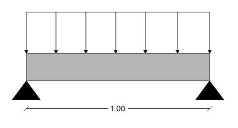
Using the rule of thumb:
Slab thickness = span/20 >> 100 / 20 = 5 cm,
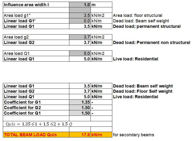
As rule of thumb shows 5cm which is not acceptable, the slab thickness can be 14cm.
Total load under ultimate limite state:
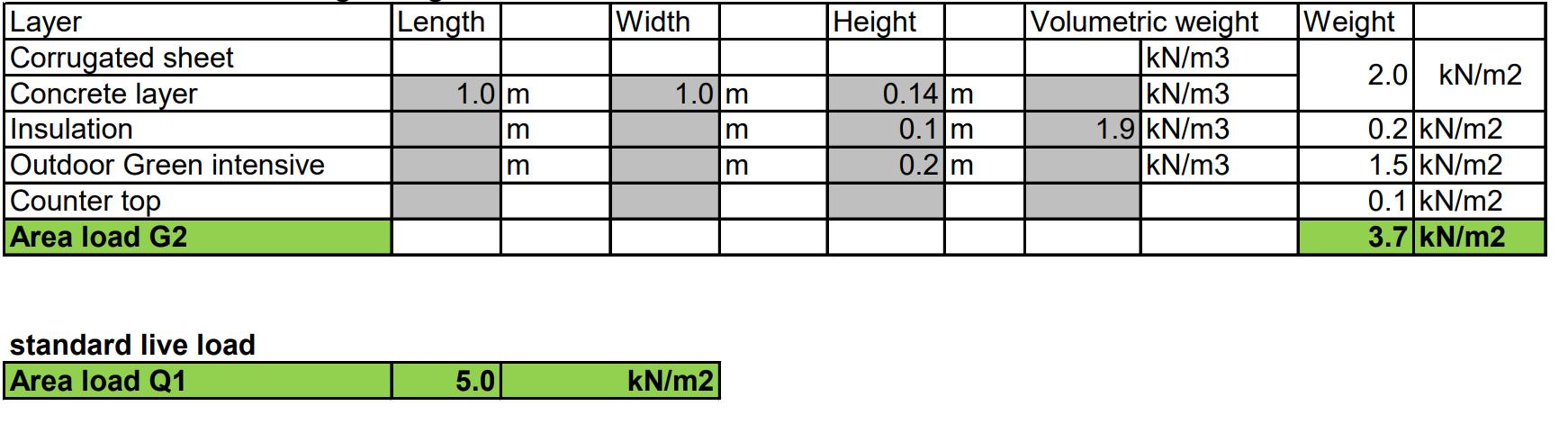
With having the amount of permanent structural deat load G1, permanent structural deat load G2 and live load Q, we obtain:
Quls =1.35 G1+1.5 G2 +1.5 Q =1.35 (3.5)+1.5 (3.7) +1.5 (5) =17.8 kN/m
>>Largest bending moment: Muls = (Quls * l^2)/8 =(17.8*1)/8 =2.22 kNm
NGM MILAN 77
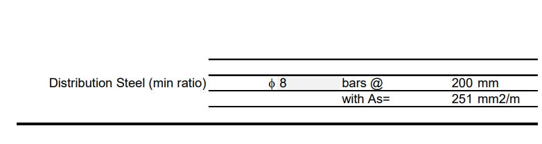
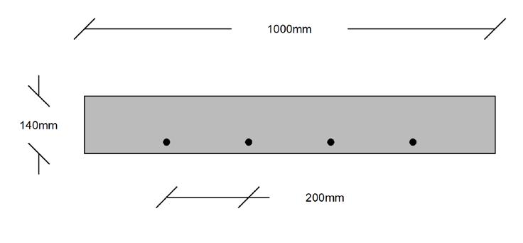
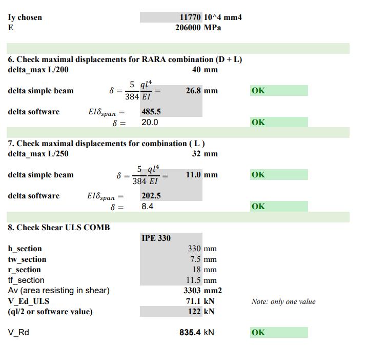
NGM MILAN E.N 78 REINFORCED CONCRETE SLAB DESIGN Module: Structures Prof. Grigor Angjeliu Academic Year 2020-2021 1. M_ED External Bending Moment Calculation M_ED_ULS 2.22 kNm 2220000 Nmm (ql^2/8 or software value) 2. Choose steel class Steel class S… 460 fyk 460 MPa γs 1.15 fyd 400 MPa 3. Choose concrete class Concrete class C… 25 fck 25 MPa γc 1.5 fcd 17 MPa 4. Beam parameters b 1000 mm usually 1/2 - 2/3 h h 140 mm usually 1/8 - 1/12 span c(cover) 25 mm bar diameter 8 mm d 111 mm effective depth 5. Section calculations 0.007 110 mm 50 mm2 Check minimum and maximum reinforcement 0.13% 4% 144.3 mm2 4440 mm2 6. Convert reinf. area into bars Bar diameter 8 mm suggestions: slab - fi 8 - fi12 mm Bar area 50.2 mm2 concrete beam fi 14mm or more Provide bars 5 per meter Provided area 251 mm2 OK bars @ 200 mm ro = A s /bd 0.23% OK 7. Check Beam Dimension 1 row Minimum width "b" 170 OK 8. Summary One way slab thickness 140 mm Tension Steel f 8 bars @ 200 mm with As= 251 mm2/m In the grey cells the numbers can be hard typed. In other cells there are already formulas. ���� = ���� ��������2 ������������ = < 0 167 ���� = ���� 0 5 + 0 25 ���� 1 134 = �������� = ���� 0 87 ������������ ���� = ����min ≤ ���� ≤ ����max , Then we put the amount of Muls = 2.22 kN/m and information about the slab such as thickness and etc to understand the if K value is oh and also the total section area of the bars.
SLAB DESIGN
NGM MILAN 79 Laboratory
part roof
LOADS
NGM MILAN E.N 80 FLOORS SLAB
ROOF
NGM MILAN 81
LOAD CALCULATIONS
CONTINUOUS BEAM DESIGN
NGM MILAN E.N 82
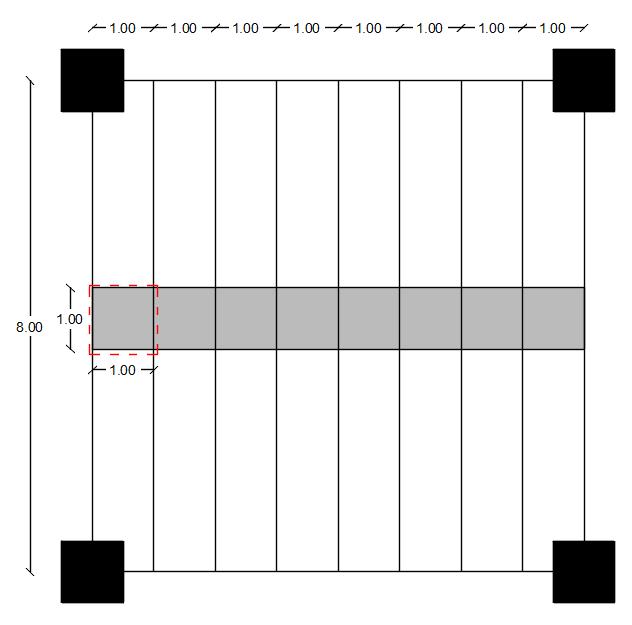
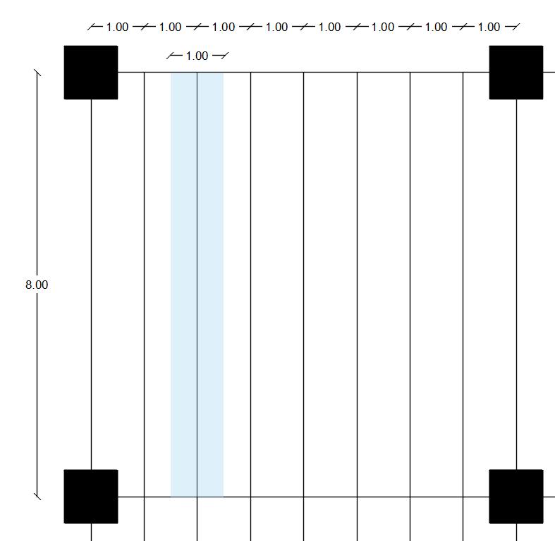
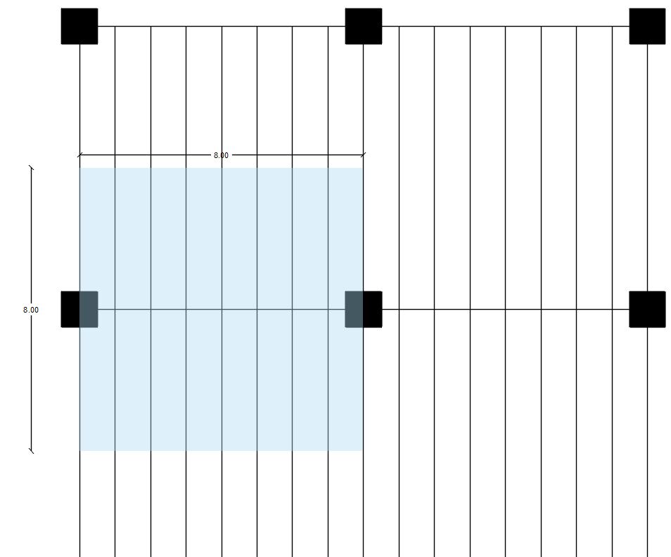
Influence area = 1m
Beam length = 8m
Calculations for the course Architectural Design Studio for Complex Constructions
Module: Structures
Prof. Grigor Angjeliu
Permanent structural deat load G1 = 3.5 kN/m2 permanent structural deat load G2 = 3.7kN/m2 Live load Q = 5 kN/m2
Academic Year 2021-2022
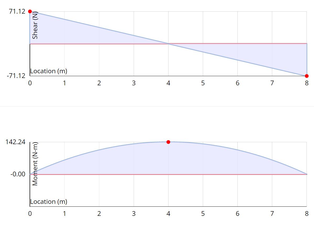
We insert the values in the excel sheet and multiply each by the influence area which is 1m. From the re we got M ed-uls. Then after finding the W ply we went to Eurocode 3, Table of design properties for flanged steel profiles and chose the section that has less Wply that what we calculated.
Secondary beam calculation
1. Load information
In the grey cells the numbers can be hard typed. In other cells there are already formulas.
Beam Lenght L 8 m 8000 mm
Influence area width I 1 m
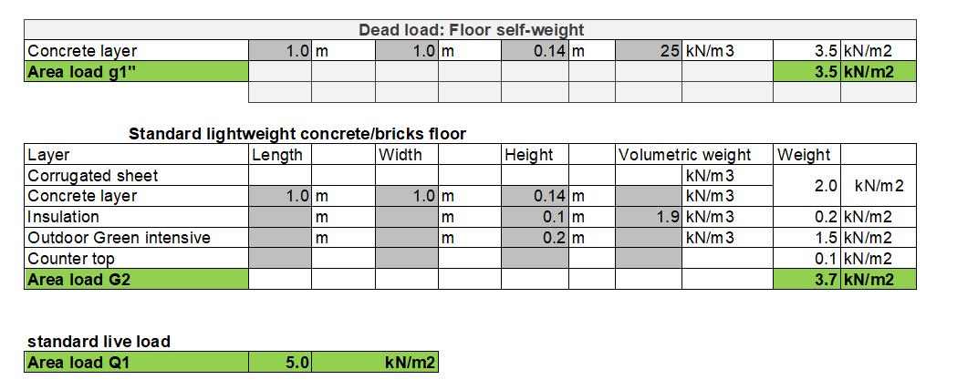
Linear load g1' 0 kN/m Dead load: Beam self weight - Structural
Area load G1'' 3.5 kN/m2 Dead load: Floor Self weight - Structural Linear load g1'' 3.5 kN/m
Area load G2 3.7 kN/m2 Linear load g2 3.7 kN/m Dead load: Floor Self weight - Non Structural
Area load Q1 5 kN/m2 Linear load q1 5.0 kN/m Live load: Residential
2. M_ED External Bending Moment Calculation
Load_ULS COMB 17.78 kN/m Load_RARA COMB 12.20 kN/m Load_LIVE COMB 5 kN/m
1.35 ����1 + 1.5 ����2 + 1.5 ����
M_ED_ULS 142.20 kNm 142200000 Nmm (ql^2/8 or software value)
3. Choose steel class Steel class S… 460 fyk 460 MPa
1.05 fyd
MPa
4. Calculate Wpl Wpl 324587 mm3 325 10^3 mm3
5. Choose the cross section such as it has a Wpl greater than the one calculated Beam chosen IPE 330 Wpl chosen 713.1 10^3 mm3 OK
γs
438
2
NGM MILAN 83 SECONDARY STEEL BEAM
Area
NGM MILAN E.N 84
of influence
PRIMARY STEEL BEAM
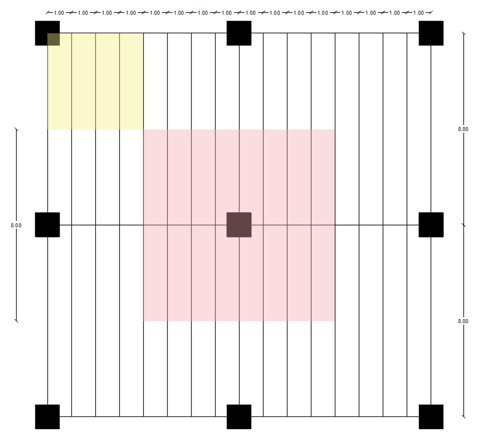
Influence area = 8m
Beam length = 8m
Permanent structural deat load G1 = 3.5 kN/m2
Calculations for the course Architectural Design Studio
permanent structural deat load G2 = 3.7kN/m2
Module: Structures Prof. Grigor Angjeliu
Live load Q = 5 kN/m2
Academic Year 2021-2022
Beam self weight - Structural| IPE 360 = 0.55 kN/m
In the grey cells the numbers can be hard typed. In other cells there are already formulas.
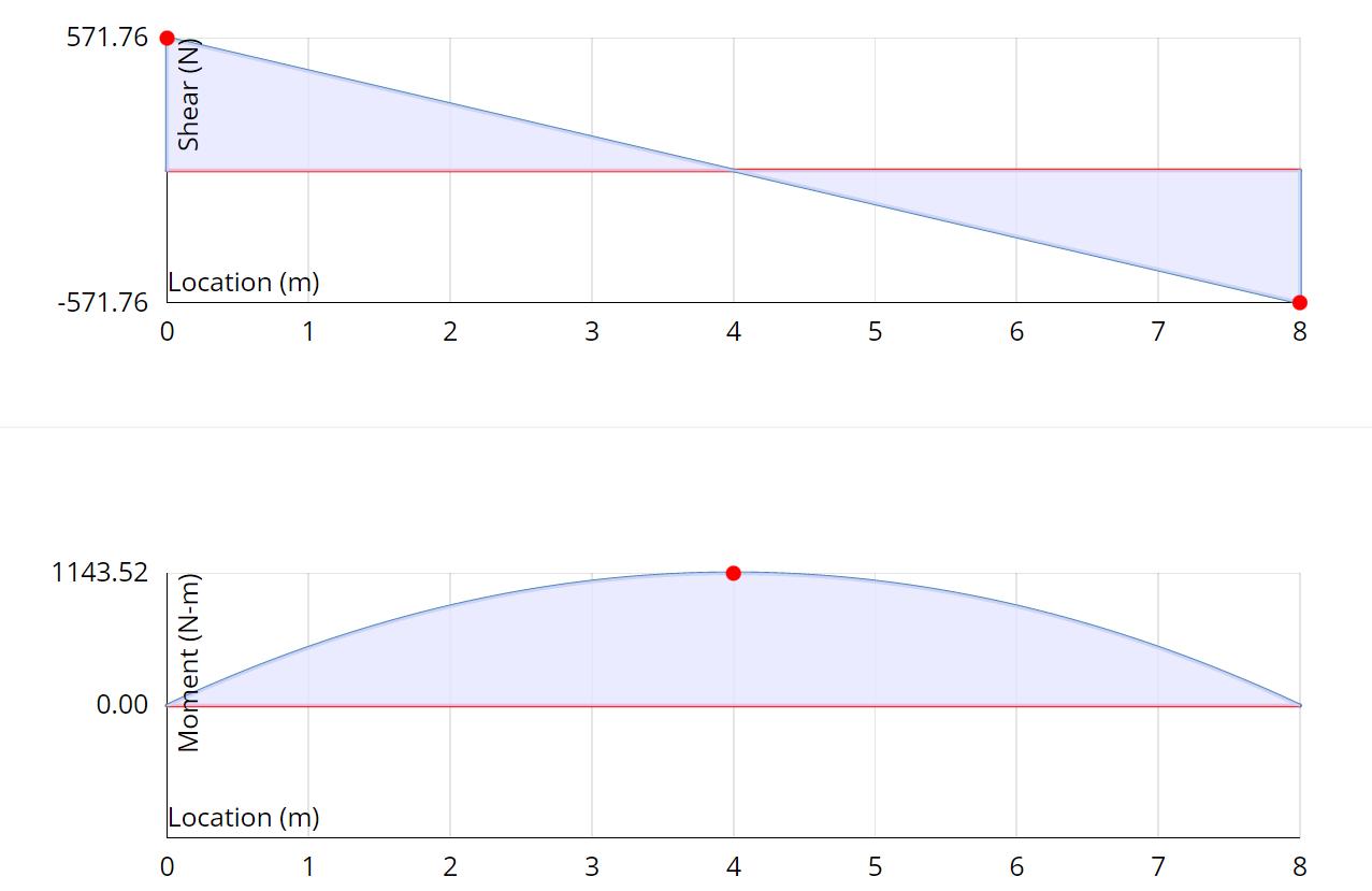
The same prcess happened here. The difference is that the dead load is summing up dead load of secondary beam and dead load of floor and mulitiplide by 1.35(safety factor).
Primary beam calculation
1. Load information
Beam Lenght L 8 m 8000 mm
Influence area width I 8 m
Linear load g1' 0.55 kN/m Dead load: Beam self weight - Structural| IPE 360
Area load G1'' 3.5 kN/m2 Dead load: Floor Self weight - Structural Linear load g1'' 28 kN/m
Area load G2 3.7 kN/m2 Linear load g2 29.6 kN/m Dead load: Floor Self weight - Non Structural
Area load Q1 5 kN/m2 Linear load q1 40.0 kN/m Live load: Residential
2. M_ED External Bending Moment Calculation
Load_ULS COMB 142.94 kN/m Load_RARA COMB 98.15 kN/m Load_LIVE COMB 40 kN/m
1.35 ����1 + 1.5 ����2 + 1.5 ����
M_ED_ULS 1143.54 kNm 1143540000 Nmm (ql^2/8 or software value)
3. Choose steel class Steel class S…
fyk
fyd
4. Calculate Wpl
Wpl
MPa
MPa
mm3 2610 10^3 mm3
5. Choose the cross section such as it has a Wpl greater than the one calculated Beam chosen HEB 550 Wpl chosen
10^3 mm3 OK Iy chosen 136700 10^4 mm4 E 206000 MPa
NGM MILAN 85
460
460
γs 1.05
438
2610254
5591
Area of influence
NGM MILAN E.N 86
NGM MILAN 87
LOAD CALCULATIONS
COLUMN DESIGN
◊ TYPES OF LOADS ON COLUMN:
◊
◊
Self weight of the column x Number of floors
Self weight of beams per run ning meter
◊
◊
Load of walls per running me ter
Total Load of slab (Dead load + Live load + Self weight)
◊
The columns are also sub jected to bending moments which have to be considered in the final design
NGM MILAN E.N 88
The underground level hosts 2 types of columns: central columns(column 2) and corner columns(columns 2).
Calculations for the course Architectural Design Studio for Complex Constructions 2
Module: Structures Prof. Grigor Angjeliu Academic Year 2020-2021
Area of influence -
In the grey cells the numbers can be hard typed. In other cells there are already formulas.
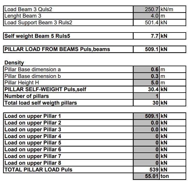
Part 3: Pillar Total Load Calculation
Pillar total load: Central column:
Central column
Load Beam 1 Quls1 258.9 kN/m
Lenght Beam 1 8.0 m Load Support Beam 1 Ruls1 1035.8 kN green force -> Lenght Beam 12 Load Beam 2 Quls2 250.7 kN/m Lenght Beam 1 8.0 m Load Support Beam 2 Ruls2 1002.8 kN red force ->
Self weight Beam 3&4 Ruls3&4 15.4 kN normal direction
PILLAR LOAD FROM BEAMS Puls,beams 2054.0 kN green+red forces -> 206.0 ton
Density
Pillar Base dimension a
m HEB 600 Pillar Base dimension b 0.3 m Pillar Height H 5.0 m
PILLAR SELF-WEIGHT Puls,self 30.4 kN Number of pillars 1 Total load self weigth pillars 30 kN
Load on upper Pillar 1 2054.0 kN 2054.0
Load on upper Pillar 2
Load on upper Pillar 3
Load on upper Pillar 4
Load on upper Pillar 5
Load on upper Pillar 6
Load on upper Pillar 7
Load on upper Pillar 8
kN 2054.0
kN 2054.0
2054.0
2054.0
2054.0
2054.0
2054.0
TOTAL PILLAR LOAD Puls 2084 kN 212.5
COLUMNS CALCULATION NGM MILAN 89
cloumn 1 column 2
0.6
0.0
0.0
0 kN
0 kN
0 kN
0 kN
0 kN
ton
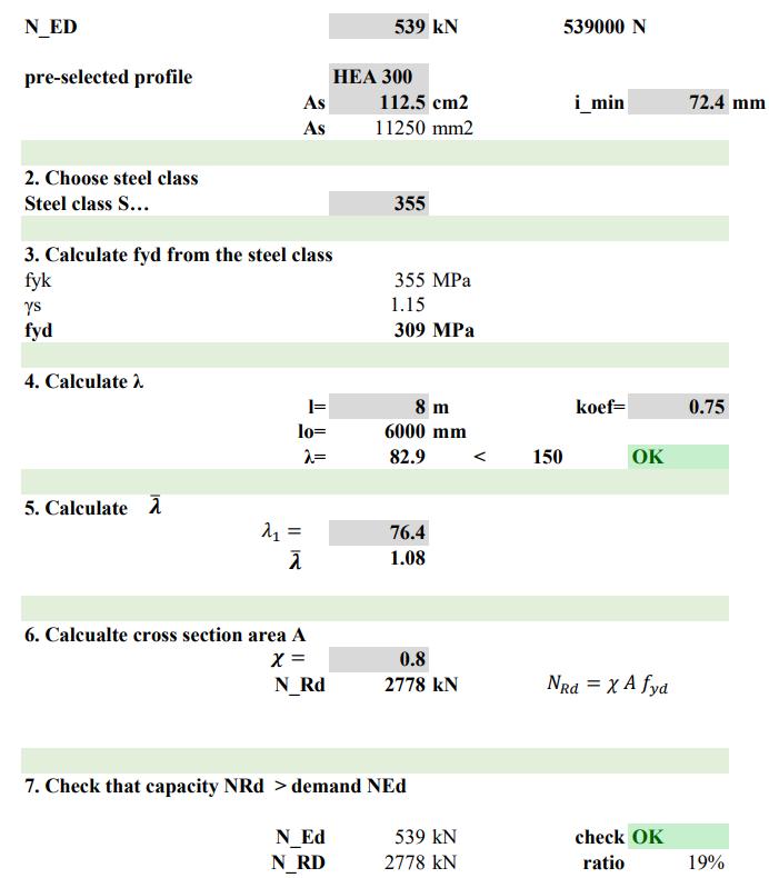
NGM MILAN E.N 90 Module: Structures Prof. Grigor Angjeliu Academic Year 2020-2021 Middle column| 8*8 1. Obtain N_ED Axial force N_ED 539 kN 539000 N pre-selected profile HEA 500 As 197.5 cm2 i_min 72.4 mm As 19750 mm2 2. Choose steel class Steel class S… 355 3. Calculate fyd from the steel class fyk 355 MPa γs 1.15 fyd 309 MPa 4. Calculate λ l= 8 m koef= 1 lo= 8000 mm λ= 110.5 < 150 OK 5. Calculate 76.4 1.45 6. Calcualte cross section area A 0.8 N_Rd 4877 kN 7. Check that capacity NRd > demand NEd N_Ed 539 kN check OK N_RD 4877 kN ratio 11% Calculations for the course Architectural Design Studio for Complex Constructions 2 In the grey cells the numbers can be hard typed. In other cells there are already formulas. ���� ����1 = ���� ���� = ������������ = ���� ���� ������������ Load check: Central column: Pillar total load: Corner column:
NGM MILAN 91 Load check: Corner column:
SPECIAL STRUCTURAL SYSTEM
NGM MILAN E.N 92
COMPLEX GEOMETRY
SAP2000 software was used to analyse and define structural elements sections. As mentioned in project description, The strustural system of the main building is consist of system of arches. The designing and analysing process of the structure is consist of different levels and layers. We started from the very initial phase to the most complicate and completed model.
The modelling process started from a combination of Rhino, grasshopper and Revit and ended in SAP2000 for the structural analysis.

The first phase was to determine how the intended geometry responded to the loads it was required to carry. Following that, we began the modelling processes in Rhino , grasshoper and later in SAP. With each stride forward, we encountered new problems and strove to overcome them one at a time. As previously stated, the geometry of our construction is curved, which is expressed

as points in the Rhino system. However, when performing the structural analysis in SAP, curved expressions defined by points will generate numerous constraints. To avoid the aforementioned issue, the model was divided into portions in rhino utilizing grasshopper and a manual technique throughout this process.


In the first step of the analysis, a single unit of Tree/Truss columns was investigated. The honeycomb structure of the slab, which was developed in Revit, was then added to the junction points in the following stage.
Given that the structure is a combination of arches in the shape of columns and an inclined piece of the roof, a segment that contained those components was required. To that goal, a fifth of the building’s structure with columns and arches was chosen for inspection.
NGM MILAN 93
1.Defining the steel section size:
Throughout the traditional calculation IPE330 section size was obtained. After performing the analysis it was discovered that IPE330 section cannot withstand the loads.
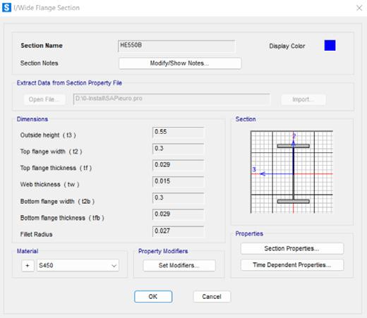
* From Define> Section properties> Frame: sections, the following sections were defined:
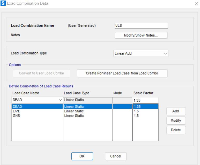
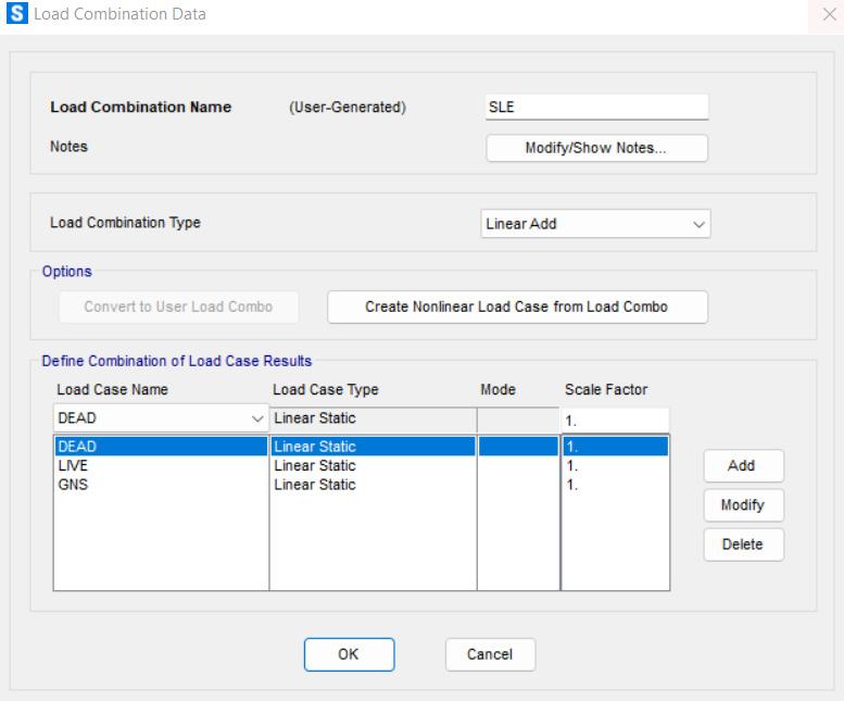
2. Defining load combinations
*From Define> Load combination:
Two load combinations named ULS and SLS.
A. For ULS load combination the load factors are:
Dead load fac. = 1.35
GNS fac. (Gravity non-structural load, G₂) = 1.5
Live load fac = 1.5 (Q₁)
Live load fac (Q₁) = 2.0 kN/m >>>>> 2.0 kN/m² x 4.0 m = 8.0 kN/m
*From Assign> Frame loads> Distributed, we have: Slab load (Distributed load in the pattern of 1by 1):
GNS fac. (Gravity non-structural load, G₂) = 8.8 kN/m²
Area load = 1 m² (each square patern in 1 by 1) >>>>> 8.8 kN/m² x 1.0 m = 8.8 kN/m
Live load fac (Q₁) = 5.0 kN/m² >>>>> 5.0 kN/m² x 1.0 m = 5.0 kN/m
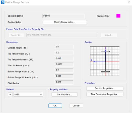
1- IPE 500 : As the section used for the Honey combed structure of slab structure.
B. For SLS load combination the load factors are:
Dead load fac = 1
GNS fac. (Gravity non-structural load, G₂) = 1
Live load fac = 1(Q₁)
3. Applying the loads
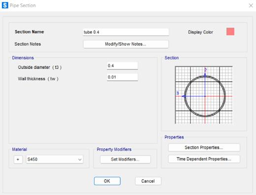
2- Tubular section with 40cm diameter: As the section used for the main Tree/Truss column.
*From Assign> Joint Loads> Forces:
Roof load (Nodal laod at intersection of lines in 45 degree):
***For the simplicity of HTE model, the part of the secondary structure was omited from the analysed model.
GNS fac. (Gravity non-structural load, G₂) = 3.7kN/m²
3- HEB550: As the section for the ring beams (Intersection part of column and slab).
Area load = 4 m² (each square patern in 2 by 2) >>>>> 3.7 kN/m² x 4.0 m = 14.18 kN/m
NGM MILAN E.N 94 DESIGNING PROCESS: SAP2000
The model was extended in the final version, accounting for almost a quarter of the entire structure. The perimeter supports, some extra columns, and eventually the building core were added to help the roof and slab remain stationary. Yet, The slab of the first floor had a large displacement, approximately 6.5cm, which was greater than the allowable displacement.
Final analysis displacement results>>allowed displacement.
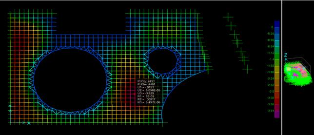
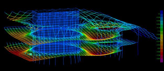
As presented in the images above, The slab of the second storey is clearly displaced for 6.2cm in this plan and elevation view.
The maximum displacement is L/250, Which equals L = 6.1m. So, 6.1/250 = 0.024m = 2.4cm 6.2 > 2.4
Not allowed displacement
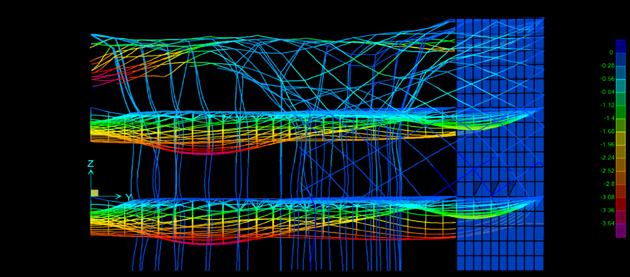
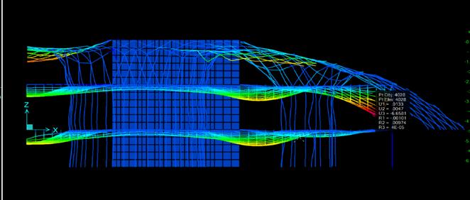
In this situation, there were two options: support it with additional columns, which was not ideal because it intruded on the architectural spaces of the ground floor. The second and chosen option was to attach this slab to the sloped section of the roof.
>>In the plan and elevations above, it is clear that the slab of the second floor is displaced for 3.6cm .
The maximum displacement is L/250 where L = 13m
So, 13/250 = 0.052m = 5.2cm 3.6 < 5.2>>allowed displacement.
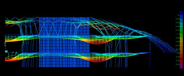
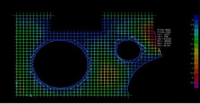
NGM MILAN E.N 96 SAP2000 FINAL RESULTS
The results of this last analysis is presented in the following images>>>>>>>>>
6.1m 13m
NGM MILAN 97
CASE STUDY
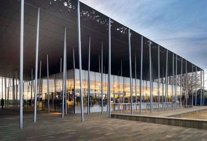
SENDAI MEDIA-THEQUE, SENDAI, JAPAN
Architect Designed in Built in Land Area Floor Area Toyo Ito 1995-1997 1998-2001 3,948 m² 2,844 m²
ABOUT
Sendai Mediatheque was built between 1995 and 2001. The Media is a glass 50 × 50 meters, 36 meters, with several plants and a series of pillars patio flowing through it from first to last. The technology is very present in this building, both internally and in the construction of the entire box. Plants are divided by use of forged steel base plates and beams in the middle as a “sandwich”, and the pillars are tubular metal soldiers. The latter are perhaps the most important aspects of the work since the run from the first to the floor and far from being orthogonal, they have a circular section that is changing as increasing in height, varying in each well one of the plants.
Ito’s Sendai Mediatheque is a pa radigmatic exploration of a new museum type. The Mediatheque gathers, preserves, exhibits, and presents media without being bound to a particular form. In his conception of the project, the ar chitect imagined the viewer as an organism with two bodies:
the tangible „primitive” body that seeks light and air and the „virtual” body that seeks information. This project marked a watershed in a growing discourse about architecture’s relationship to the virtual.
FORM
The building consists of three elements: a series of weaving structural tubes, floor plates, and skin. It is conceived as a small piece cut out of an infinite structure, a gesture most evident in the lack of differentiation between the building’s cross section and its understated facade. This implies that the building is a visible part of an infinite fabric that oscillates between materiality and immateriality—between the primitive and the virtual. Inside, aluminum partitions fuzzily reflect the structural tubes, which also seem to extend infinitely. Media labs, interactive stations, digital displays, and countless other technological happenings are flexibly integrated into the space without disrupting
the building’s versatility and its capability of adapting to new media and new ideas.
CONCEPT
The conceptual thinking behind the project was the blending of real and conceptual. the building is composed of 13 independent steel-ribbed shafts (tubular columns: mainly steel-tube truss construction) and 7 steelribbed slabs (“honeycomb”slabs: sandwiched steel-plate construction), giving each floor a different floorplan. basement (b1) structures feature seismic energyabsorbing mechanisms. The tubular column structures serve as light wells, with rooftop devices to reflect sunlight down the tubes into the building. The vertical connector “pipelines” serve as a network for cables, wiring, elevators and stairways. Each vertical shaft varies in diameter and is independent from the facade, this allows for a free floor plan that changes from level to level.
NGM MILAN E.N 98
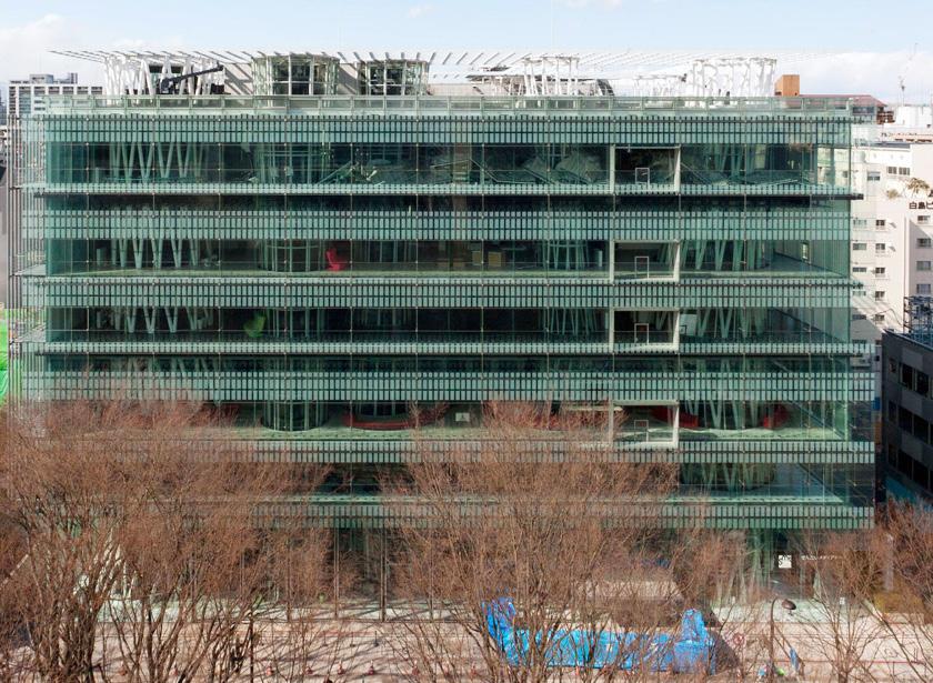
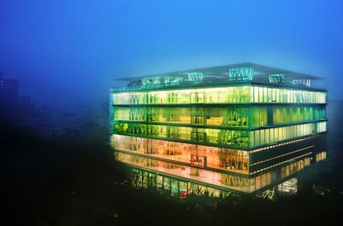
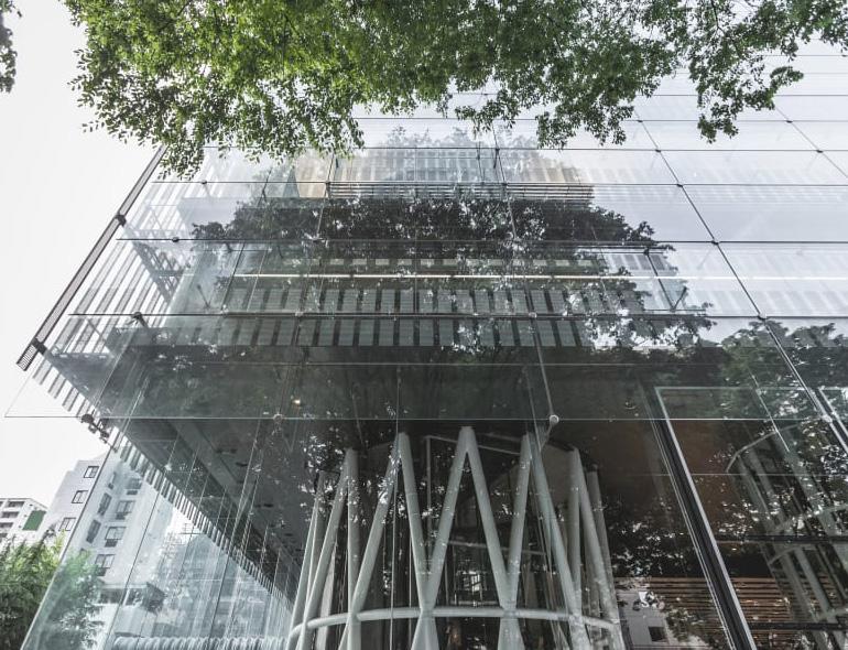
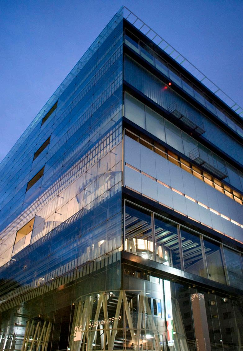
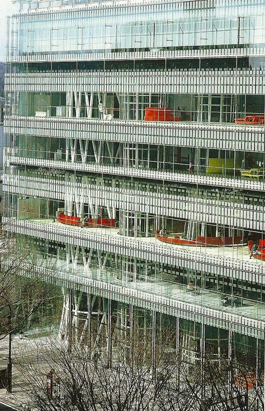
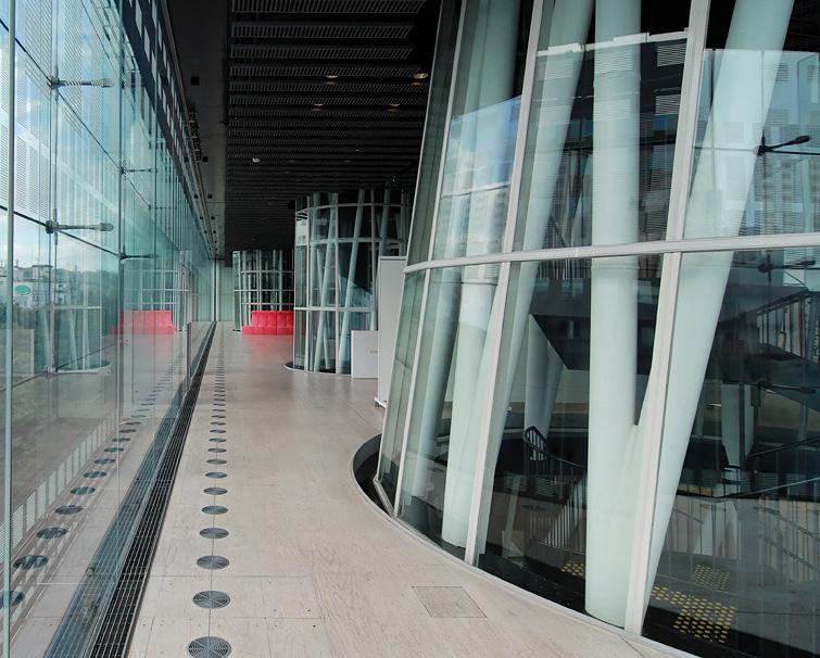
NGM MILAN 99
FLOOR
FLOOR
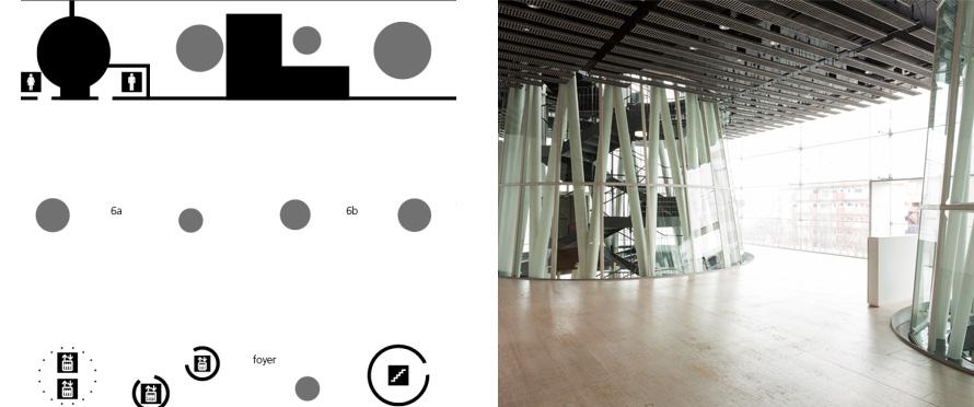
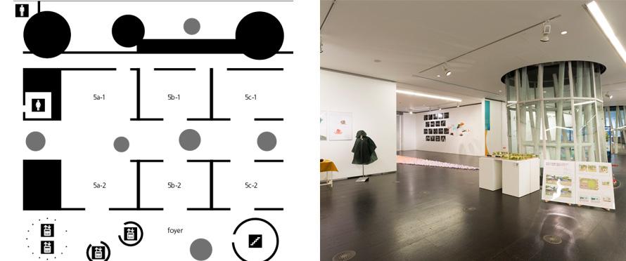
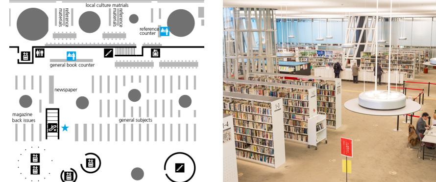
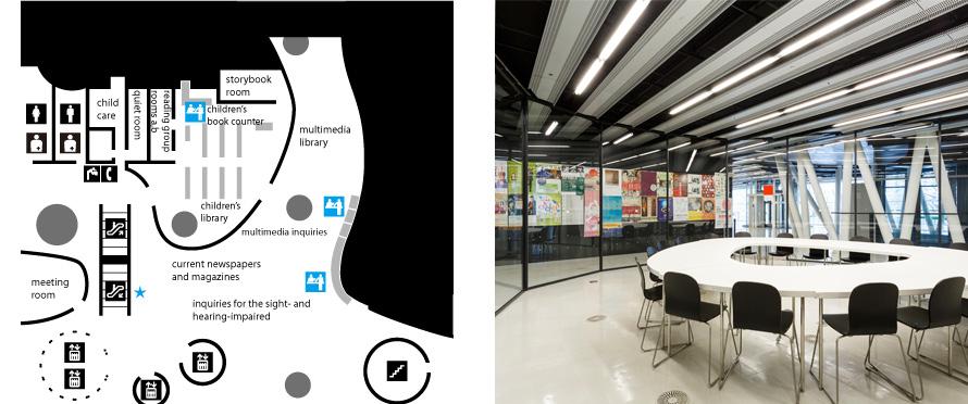
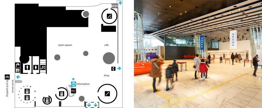
NGM MILAN E.N 100 1ST
PLAN 2ND
PLAN 4TH AND 5TH F.PLANS ARCHITECTURAL PLANS 3RD FLOOR PLAN 6TH FLOOR PLAN
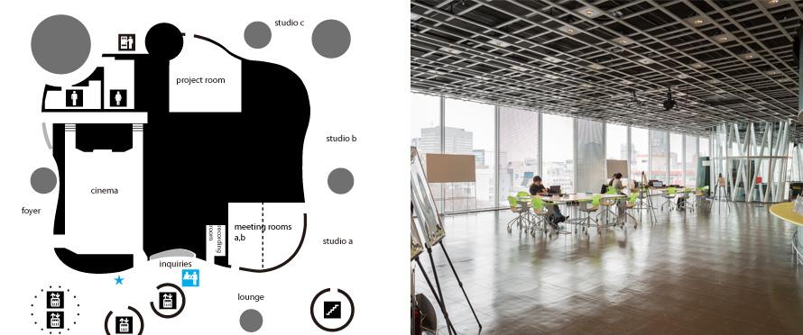
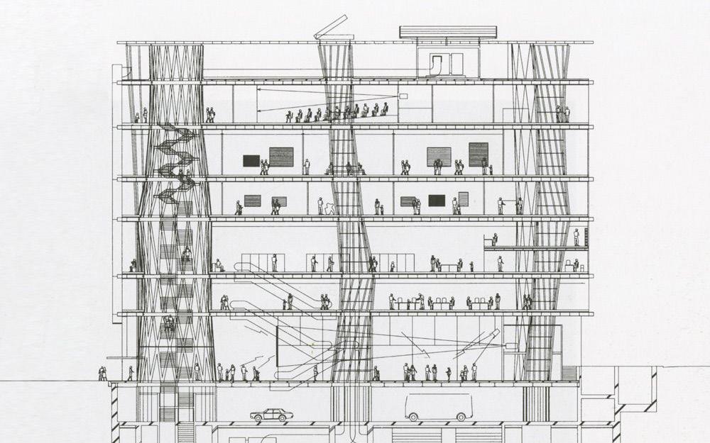
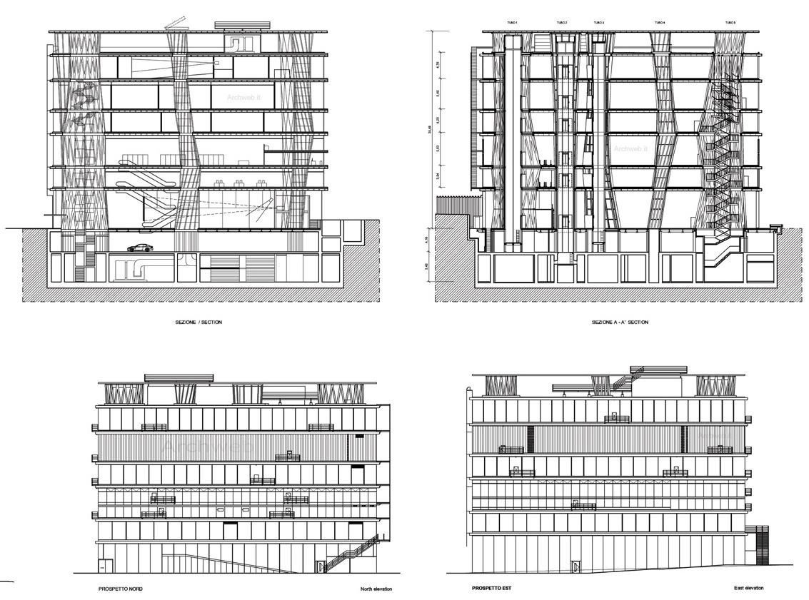
NGM MILAN 101 SECTIONS AND ELEVATIONS: 6TH FLOOR PLAN
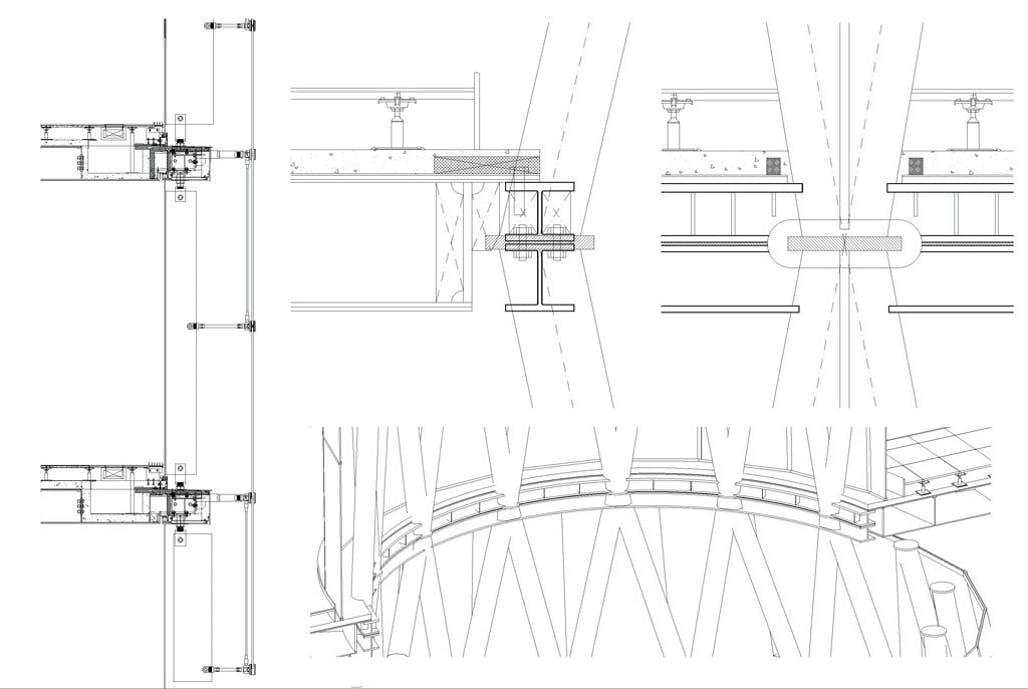
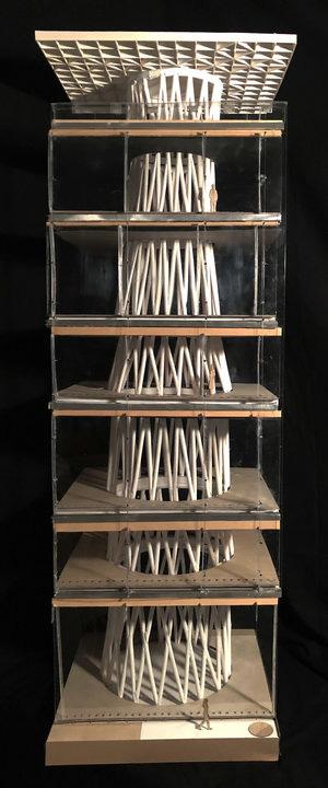
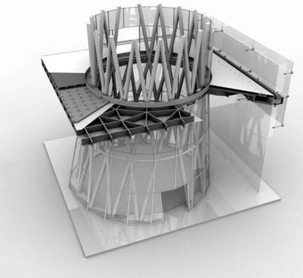
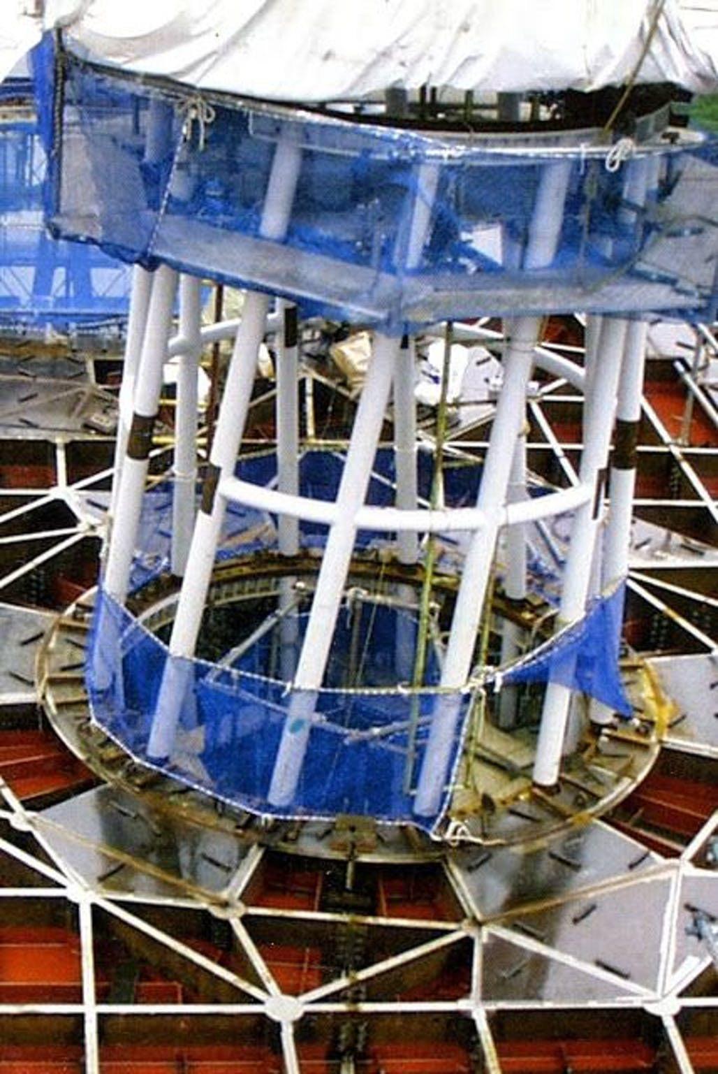
NGM MILAN E.N STRUCTURAL DETAILS (COLUMNS AND CONNECTION TO RING BEAMS)
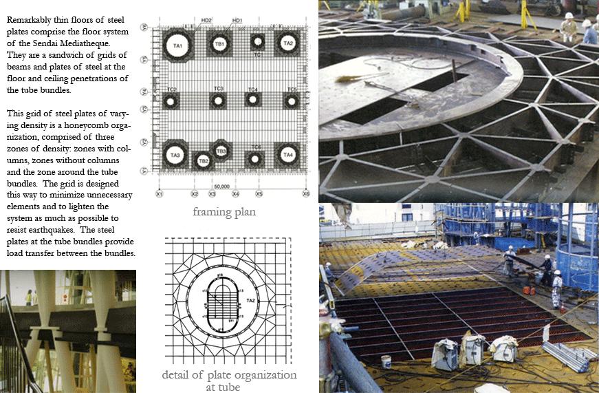
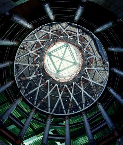
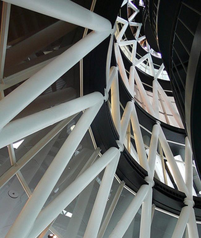
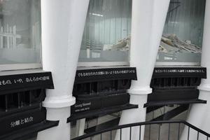
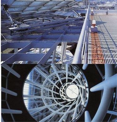
NGM MILAN 103
SERVICE DESIGN
OPAQUE WALLS AND ROOF STRATIGRAPHY TRANSPARENT U VALUE
SUMMER HEAT LOAD WINTER HEAT LOAD BUILDING SYSTEMSAIR QUALITY CONTROL COLD & HOT WATER SUPPLY
DRAINAGE SYSTEM
NGM MILAN E.N 104
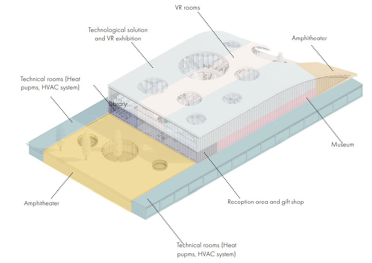
NGM MILAN 105
SERVICE DESIGN
OPAQUE WALLS AND ROOF STRATIGRAPHY
OPAQUE WALLS & ROOF STRATIGRAPHY
The first step to establish the most efficient way to provide air quality services to the building, Is to calculate the heat loads within it(summer/winter). This step con tains an analysis of the building envelope’s stratigraphy, to cal culate the U and R values. the process is done in the following method;The building has four fa cades that are connected to the exterior. The front elevation from west is a completely transparent, frameless Pilkington component. (axonometric view pg. 101)
The north and south eleva tions are then made up of both opaque and transparent components (same producer).
The roof is partly curved and sloped to the ground at the east elevation. As a result, this eleva tion’s opaque component will have the same layers as the roof. Furthermore, the transparent component of this elevation is manufactured by the same
company as previously explained. The Opaque, transparent and roof stratigraphy are as presen ted in the following page.
NGM MILAN E.N 106
NORTH/SOUTH FACADE WEST FACADE SYSTEM
S
r a t
g
p h y
FACADE SYSTEM STRATIGRAPHY
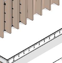
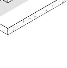
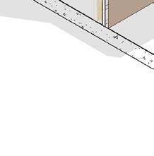
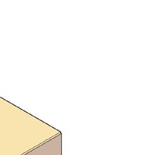
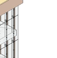
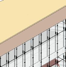
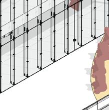
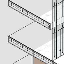
S
1/Opaque wall stratifications and data in North and South
1/Opaque wall stratifications and data in North and South
Material Density (kg/m3) Thickness (m) Mf,p (kg/m2) λ (W/mk) R (m2k/W) U (W/m2k)
Material Density (kg/m3) Thickness (m) Mf,p (kg/m2)
Aluminium composite 2,710 0.004 10.84 0.44 0.01
(W/mk) R (m2k/W) U (W/m2k)
Aluminium composite 2,710 0.004 10.84 0.44 0.01
Air cavity 1.28 0.05 0.06377 0.025 2.00
Air cavity 1.28 0.05 0.06377 0.025 2.00
Mineral wool insulation 70 0.1 7 0.034 2.94
Mineral wool insulation 70 0.1 7 0.034 2.94
Reinforced Concrete 2500 0.35 875 2.6 0.13
Reinforced Concrete 2500 0.35 875 2.6 0.13
Fire proof mortar 350 0.01 3.5 0.087 0.11 896.4 R total 5.20 0.19
Fire proof mortar 350 0.01 3.5 0.087 0.11 896.4 R total 5.20 0.19
2/Roof stratifications and data
2/Roof stratifications and data
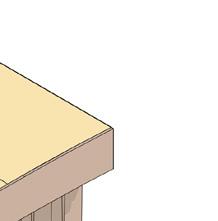
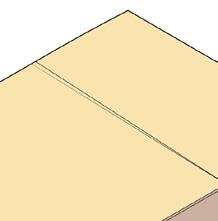
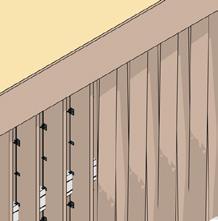
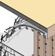
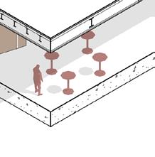
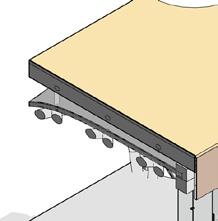
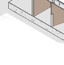
Total (kg/m2)
Total (kg/m2)
Material Density (kg/m3) Thickness (m) Mf,p (kg/m2) λ (W/mk) R (m2k/W) U (W/m2k)
Material Density (kg/m3) Thickness (m) Mf,p (kg/m2) λ (W/mk) R (m2k/W) U (W/m2k)
Fertile green roof 15 0.1 1.5 0.41 0.24
Fertile green roof 15 0.1 1.5 0.41 0.24
Sealing element (PVC) 1.28 0.042 0.0535668 0 0.00
EPS thermal insulation 70 0.032 0.03 0.034 0.94
Sealing element (PVC) 1.28 0.042 0.0535668 0 0.00 EPS thermal insulation 70 0.032 0.03 0.034 0.94
Vapor barier 2500 0.035 87.5 0 0.00
Vapor barier 2500 0.035 87.5 0 0.00
Slopping layer 2300 0.032 73.14 3.2 0.01
Slopping layer 2300 0.032 73.14 3.2 0.01


Reinforced concrete 2500 0.14 350 3.2 0.04 512.2 R total 1.24 0.81
Reinforced concrete 2500 0.14 350 3.2 0.04 512.2 R total 1.24 0.81
Total (kg/m2)
Total (kg/m2)
**This data will also be used for the Eastern façade as it is a
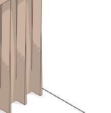
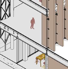


the slopping roof.
2/Glass stratigraphy
2/Glass stratigraphy
Producer: Pilkington
Producer: Pilkington
Type: Double glazed
Layers: two layers of glass 10mm and 6mm + 16mm air cavity R-value(thermal resistance) for glass : 0.3492 m2k/W R-value(thermal resistance) for air gap: 0.176 m2k/W U-value=1/R total =1/(2(0.3492)+0.176)=1.14W/m2k
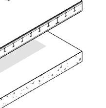

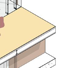

Type: Double glazed Layers: two layers of glass 10mm and 6mm + 16mm air cavity R-value(thermal resistance) for glass : 0.3492 m2k/W R-value(thermal resistance) for air gap: 0.176 m2k/W U-value=1/R total =1/(2(0.3492)+0.176)=1.14W/m2k
S U M M E R H E A T L O A D
S U M M E R H E A T L O A D
1/Sensible
107
λ
1-1/Sensible Cosnstant Equipment Heat (W) Amount Total (W) Photocopy 450 38 17100 1/Sensible
**This data will also be used for the Eastern façade as it is a part of the slopping roof.
I n t e r n a l l o a d s
t r a t i g r a p h y
1-1/Sensible Cosnstant Equipment Heat (W) Amount Total (W) Photocopy 450 38 17100
part of
I n t e r n a l l o a d s
t
i
r a
SERVICE DESIGN
SUMMER HEAT LOAD
The term heat load refers here to the computed thermal quantity used to determine the capacity of a cooling system to keep the temperature in the structure be low a certain threshold.
The thermal storage qualities of the building are important in cooling load estimates (sum mer period), because the time at which the space may realize the heat gain as a cooling load will be significantly offset from the time the heat began to flow.
To do so, all potential heat-pro ducing activities (heat sources) within that structure or space were considered, including so lar radiation, people, machines, lighting, kitchens, computers, and so on.
Heat gain is categorized ac cording on how it enters the space: a. Solar radiation through trans parent surfaces such as windows b. Heat conduction through exte rior walls and roofs c. Heat conduction through inte rior partitions, ceilings and floors d. Heat generated within the space by occupants, lights, appli ances, equipment and processes
e. Loads as a result of ventilation and infiltration of outdoor air f. Other miscellaneous heat gains
Total Heat load (QT ) = Sensible (Qs) +Latent (QL)
The summer heat loads were cal culated using a simplified method known as the Carrier method. We began by calculating the internal load. We estimated sensible con stant and variable load, as well as latent sensible and variable load, in two phases.
NGM MILAN E.N 108
2/Glass stratigraphy
Producer: Pilkington
Type: Double glazed
Layers: two layers of glass 10mm and 6mm + 16mm air cavity
R-value(thermal resistance) for glass : 0.3492 m2k/W R-value(thermal resistance) for air gap: 0.176 m2k/W U-value=1/R total =1/(2(0.3492)+0.176)=1.14W/m2k
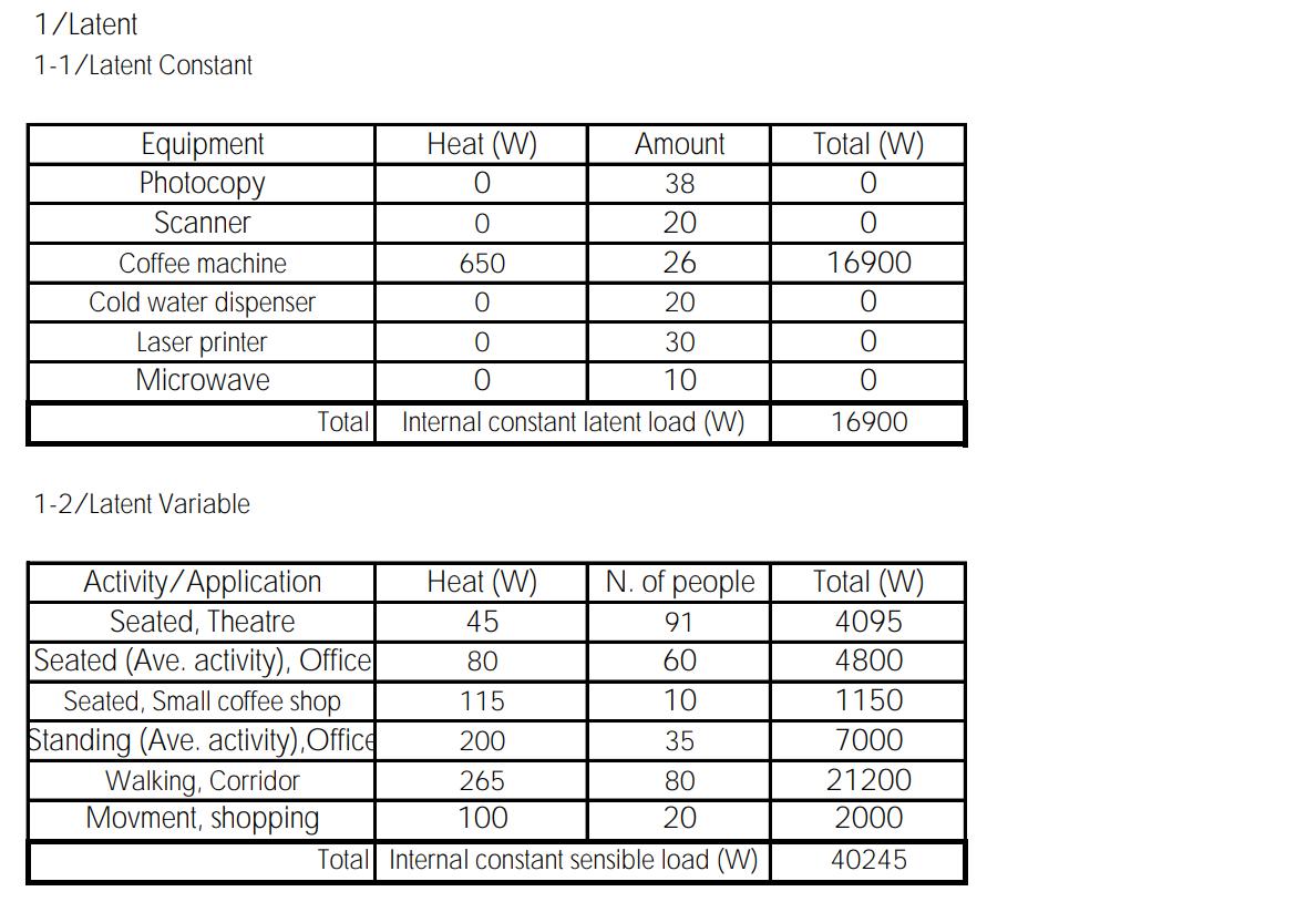
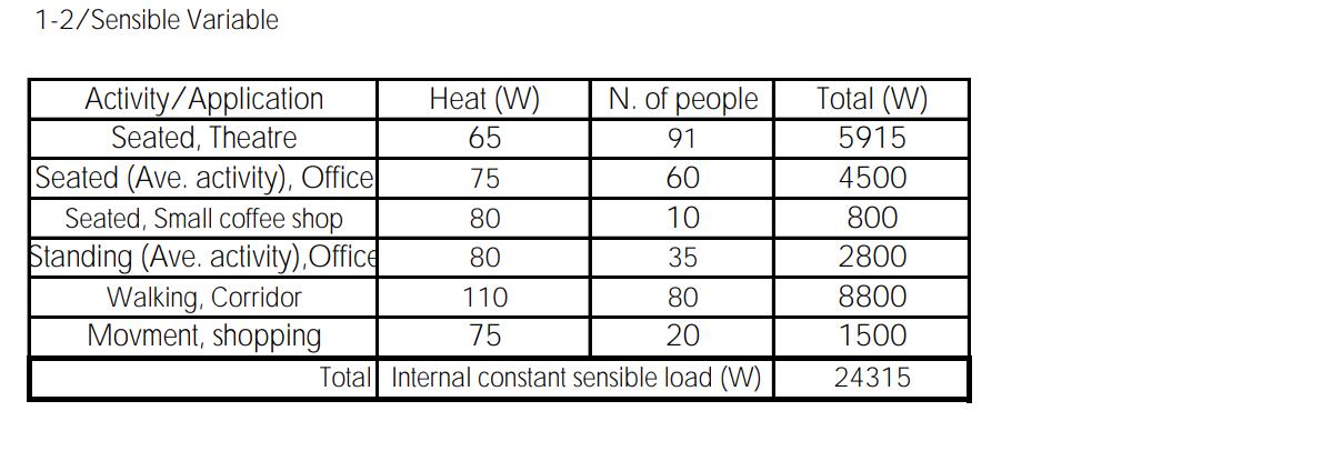
SUMMER HEAT LOAD
PHASE ONE
Listing all potential heat-producing activities (heat sources) within that structure:
S U M M E R H E A T L O A D
1/Sensible Internal constant sensible load (W)
1-1/Sensible Cosnstant Equipment Heat (W) Amount Total (W) Photocopy 450 38 17100 Scanner 1500 20 30000 Coffee machine 1000 26 26000
Cold water dispenser 1750 20 35000 Laser printer 350 30 10500 Microwave 400 10 4000 Total 122600
NGM MILAN 109
I n t e r n a l l o a d s
SUMMER HEAT LOAD
PHASE TOW
In this phase, we used both the previously described formula and data for our Site (MIND Milano), and then entered them to the excel sheet provided.
determined the amount of cooling load based on the Excel results.
Dati Generali
Località Milano
Temperatura esterna progetto Te 32 °C
Escursione termica giornaliera* ΔTe 12 °C
Umidità assoluta esterna massima Xe 14.4 g/kg
Latitudine 45 ° 0 '
Temperatura ambiente progetto Ta 27 °C
Umidità ambiente progetto Xa 12.7 g/kg
Massa in pianta*** Ma 730 kg/mq
Portata aria esterna di rinnovo V 27527.5 mc/h
Dati Involucro
Esposizione
Note
*Valore compreso fra 5 e 17 °C
**Valore compreso fra:
pareti verticali: 100 e 700 kg/mq
orizzontale sole: 50 e 400 kg/mq orizzontale ombra: 100 e 300 kg/mq
***Valore compreso fra 150 e 730 kg/mq
RIEMPIRE CAMPI CON BORDO ARANCIONE
Superfici Opache Finestre
Up Mf,p** Sp UF f F=SC Fvs SF W/(mq K) kg/mq mq W/(mq K) mq
NORD 0.19 700 1014.2 1.14 0.95 0.82 309.04
EST 0.19 700 100.0 1.14 0.95 0.82 309.04
OVEST 0.19 700 760.0 1.14 0.95 0.82 309.04
SUD 0.19 700 380.5 1.14 0.95 0.82 309.04
ORIZZONTALE OMBRA 0.19 100
ORIZZONTALE SOLE 0.19 512.2 2772.6
Carichi Interni
Carico interno sensibile costante Qint,s,cost 122600 W
Carico interno latente costante Qint,l,cost 16900 W
Carichi interni totali
Ora Costante Variabile Costante Variabile H Qint,s,cost Qint,s,var Qint,l,cost Qint,l,var h W W W W
122600 7294.5 16900 12073.5
122600 8510.25 16900 14085.75
122600 9726 16900 16098
122600 10941.75 16900 18110.25
122600 14589 16900 24147
122600 15804.75 16900 16098
122600 9726 16900 28171.5
122600 17020.5 16900 12073.5
122600 19452 16900 28171.5
122600 20667.75 16900 32196
122600 20667.75 16900 32196
122600 17020.5 16900 12073.5
122600 14589 16900 24147
122600 7294.5 16900 12073.5
122600 4863 16900 8049
122600 0 16900 0
122600 0 16900 0
NGM MILAN E.N 110
8
9
10
11
12
13
14
15
16
17
18
19
20
21
22
23
24
We
Finestre
Finestre Irraggiamento
EST Pareti
-933.6 -1,374.0
3,683.4 3,358.4
Finestre Trasmissione -1,162.6 -669.4 -176.2 264.2 704.6 1,145.0 1,585.4 1,761.5 1,585.4 1,409.2 1,233.1 810.3 387.5 -52.8 -493.2 -933.6 -1,374.0
Finestre Irraggiamento 42,154.0 48,353.1 49,592.9 47,113.2 42,154.0 37,194.7 34,715.0 32,235.4 28,515.9 27,276.1 24,796.4 22,316.8 19,837.2 17,357.5 16,117.7 14,877.9 12,398.2
OVEST Pareti Trasmissione
Finestre Trasmissione -1,162.6 -669.4 -176.2 264.2 704.6 1,145.0 1,585.4 1,761.5 1,585.4 1,409.2 1,233.1 810.3 387.5 -52.8 -493.2 -933.6 -1,374.0
Finestre Irraggiamento 7,308.9 6,644.5 6,644.5 6,644.5 6,644.5 8,637.8 12,624.5 17,940.1 23,920.1 27,906.8 29,235.7 25,249.0 21,926.8 19,269.0 17,275.7 15,282.3 13,953.4
SUD Pareti Trasmissione
Finestre Trasmissione -1,162.6 -669.4 -176.2 264.2 704.6 1,145.0 1,585.4 1,761.5 1,585.4 1,409.2 1,233.1 810.3 387.5 -52.8 -493.2 -933.6 -1,374.0
Finestre Irraggiamento 16,117.7 24,796.4 34,715.0 43,393.8 52,072.5 59,511.5 63,230.9 63,230.9 59,511.5 52,072.5 45,873.4 40,914.1 35,954.8 32,235.4 28,515.9 26,036.3 23,556.6
OMBRAPareti Trasmissione
OR. SOLE Pareti Trasmissione 1,210.2 1,210.5 1,526.5 1,790.5 2,634.0 4,425.1 5,584.3 6,164.4 7,376.0 8,271.5 8,850.7 8,850.4 8,270.9 7,954.6 7,953.7 7,373.9 6,794.2
INFILTRAZIONI -30,431.7 -17,521.3 -4,610.9 6,916.3 18,443.4 29,970.6 41,497.7 46,108.6 41,497.7 36,886.9 32,276.0 21,209.9 10,143.9 -1,383.3 -12,910.4 -24,437.5 -35,964.7
CARICHI INTERNI Costanti 122,600.0 122,600.0 122,600.0 122,600.0 122,600.0 122,600.0 122,600.0 122,600.0 122,600.0 122,600.0 122,600.0 122,600.0 122,600.0 122,600.0 122,600.0 122,600.0 122,600.0
7,294.5 8,510.3 9,726.0 10,941.8 14,589.0 15,804.8 9,726.0 17,020.5 19,452.0 20,667.8 20,667.8 17,020.5 14,589.0 7,294.5 4,863.0 0.0 0.0
Totale 165,178 196,358 224,581 246,090 268,131
extracted the highest amount
the sensible and latent parts of the spreadsheet. Then we sum med them up so that they may be considered as a factor in deciding on an AHU.
to the excel file:
Massimo carico sensibile = 319821W
Massimo carico latente = 88109W
W
NGM MILAN 111 Ora del giorno 8 9 10 11 12 13 14 15 16 17 18 19 20 21 22 23 24 NORD Pareti Trasmissione 0.0 0.0 0.0 0.0 0.0 0.0 0.0 0.0 0.0 0.0 0.0 0.0 0.0 0.0 0.0 0.0 0.0
Trasmissione -1,162.6 -669.4 -176.2 264.2 704.6 1,145.0 1,585.4 1,761.5 1,585.4 1,409.2 1,233.1 810.3 387.5 -52.8 -493.2
3,575.0 4,441.7 5,091.7 5,633.4 6,175.0 6,608.4 7,150.0 7,475.0 7,800.0 8,016.7 6,391.7 5,633.4 4,983.4 4,550.0 4,008.4
Trasmissione 0.0 0.0 0.0 0.0 0.0 0.0 0.0 0.0 0.0 0.0 0.0 0.0 0.0 0.0 0.0 0.0 0.0
0.0 0.0 0.0 0.0 0.0 0.0 0.0 0.0 0.0 0.0 0.0 0.0 0.0 0.0 0.0 0.0 0.0
0.0 0.0 0.0 0.0 0.0 0.0 0.0 0.0 0.0 0.0 0.0 0.0 0.0 0.0 0.0 0.0 0.0
OR.
0.0 0.0 0.0 0.0 0.0 0.0 0.0 0.0 0.0 0.0 0.0 0.0 0.0 0.0 0.0 0.0 0.0
Variabili
289,333 303,470 319,821 317,015 309,335 295,624 267,035 239,856 209,666 186,451 161,682 141,200 MASSIMO CARICO SENSIBILE Ora del giorno 8 9 10 11 12 13 14 15 16 17 18 19 20 21 22 23 24 INFILTRAZIONI 39012.9 39012.9 39012.9 39012.9 39012.9 39012.9 39012.9 39012.9 39012.9 39012.9 39012.9 39012.9 39012.9 39012.9 39012.9 39012.9 39012.9 CARICHI INTERNI Costanti 16900.0 16900.0 16900.0 16900.0 16900.0 16900.0 16900.0 16900.0 16900.0 16900.0 16900.0 16900.0 16900.0 16900.0 16900.0 16900.0 16900.0 Variabili 12073.5 14085.8 16098.0 18110.3 24147.0 16098.0 28171.5 12073.5 28171.5 32196.0 0.0 12073.5 24147.0 12073.5 8049.0 0.0 0.0 Totale 67986.4 69998.6 72010.9 74023.1 80059.9 72010.9 84084.4 67986.4 84084.4 88108.9 55912.9 67986.4 80059.9 67986.4 63961.9 55912.9 55912.9 MASSIMO CARICO LATENTE CARICO SENSIBILE (POTENZA IN W) 319821 CARICO LATENTE (POTENZA IN W) 88109 We
from
According
1-
2-
Total = 407930
= 407. 930 kW
SERVICE DESIGN
WINETR HEAT LOAD
In calculating heating load esti mations during the winter season, Accounting for solar heat gain or internal heat gains is typically NOT provided, and thermal sto rage effects of building structure are typically ignored.
Sensible and latent heat load for winter It are calculated in accor dance with UNI EN 12831, ta king into consideration the most unfavourable working conditions.
When estimating sensible ther mal loads, undefined walls (then heat exchange is corrected with the pertinent thermal bridge co efficient) are taken into account.
The solar and internal heat gain are ignored (since they both contribute to indoor space he ating as free heat load gain).
****There is no standard for latent heat loads since, in general, the external air flow rate in air systems is humidified from external to in ternal conditions in the AHU.
������,��= ����,i + ����,i+ ��h��,i ����,�� = Thermal dispersion by
transmission [W]
����,i = Thermal dispersion by ven tilation [W]
��h��,�� =Extraction power needed for compensating the effects of the intermitting heating [W]
The computation is carried out utilizing the reference design of the respective standards.
NGM MILAN E.N 112
SERVICE DESIGN
AIR QUALITY CONTROL
The key purpose of service desi gn is to create the best solution for buildings that maintains the optimal balance between ener gy savings, high quality ambient conditions inside the structure, and maximizing economic reso urces.
Building system control must be based on trustworthy indoor air measurements in order to obtain long-term results. By maintaining good indoor air quality, the objec tive is to improve the conditions inside a building and ensure the comfort and safety of its users or occupants. Optimization also aids in reducing the building’s energy usage, which decreases the buil ding’s environmental footprint. Many different factors influence indoor air quality and energy usa ge in a structure. The most criti cal factors to monitor in a typical building under normal settings (excluding cases of indoor air pol lution) are carbon dioxide, relati ve humidity, and temperature.
A carbon dioxide level in a place is an useful sign of effective ven tilation. Elevated carbon dioxide levels are not normally harmful to
health, but they can cause stiff ness and odour, as well as tired ness in elevated doses, indicating the need for increased ventila tion. The relative humidity in a building can also have an impact on the health of its occupants. Pe ople who work or live in mid-ran ge relative humidity, for example, are less prone to get respiratory illnesses. Relative humidity is also important for allergenic mites and fungus populations. Indoor relative humidity levels should ideally remain between 40 and 60 percent to reduce the bulk of negative health impacts.
Relative humidity in indoor air also affects how temperature is perceived; people feel colder in dry air than in humid air. So, ke eping humidity at an optimum level helps keep the temperature slightly lower and therefore save energy.
•
In recent years, the Covid-19 pandemic has raised conscio usness about the significance of indoor air quality, raising awareness of the need for appropriate ventilation and a clean interior environment.
◊
in terms of building systems, the following factors are in creasingly being evaluated more closely:
Increased outdoor fresh air flow
◊
Improved air filtration stage for air recirculation
◊ Adequate social isolation & DPI
Indoor air quality is dependent on external fresh air to reduce the number of air pollutants. UNI 10339 is the Italian standard, whi le ISO EN UNI 16798 is the EN standard, which enforces a speci fic amount of fresh air according to the type of indoor environ ment and the number of people.
These needs can be met by either a natural ventilation system or a mechanical ventilation system.
NGM MILAN E.N 114
MECHANICAL VENTILATION SYSTEM
All Air Handeling Unit
The mechanical ventilation sys tem used for the NGM building is an AHU; all air handling system, which is joined by a heat pump and a water chiller and uses the groundwater around the site to keep the building at a comfor table temperature based on the season.
AHUs are found in medium to large commercial and industrial buildings.They are usually located in the basement, on the roof or on the floors of a building. In this project , they are located on the undeground level within a dedi cated service area.
AHU EXPLAINED
The air handling units in a buil ding condition and distribute the air. They take fresh outside air, clean it, heat or cool it, poten tially humidify it, and then force it through ductwork to the desi gnated regions within a building.
Most units will have an additio nal duct run to then pull the used dirty air out of the rooms, back to the AHU, where a fan will di scharge it back to atmosphere. The basic model contains the two AHU housing for flow and return air.
Dampers
Are located at the inlet of the fre sh air housing and the discharge of the return air .
Filters
Catch all the dirt and dust etc from entering the ahu and the building.
Pressure sensor
Located accross each bank of filters. measures how dirty the filters are and warn the engine ers when it’s time to replace the filters.
Cooling and heating coils
They heat or cool the air. The air temperature of the supply air is measured as it leaves the ahu and enters the ductwork.The co ils are heat exchangers, inside the coil is a hot or cold water.
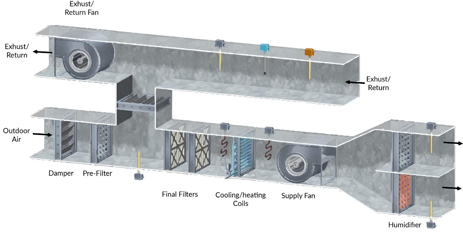
Fan
Exhust the air in from outside and then through the dampers, filters and coils and then push it out into the ductwork around the building.
Ductwork
Coming in and out of the building to send the air around the interio to the designed areas and outdo or to the atmosphere.
Humidity sensor
Located at the outlet of the sup ply AHU to measure the moistu re in the supply air. Programmed with a setpoint value for how much moisture should be in the air by design.If the air’s moisture content is below this value mo isture needs to be indusced into the air using a humidifier.
Humidifier
Either add steam or spray a wa ter mist into the air. If the air is too humid then it can be reduced through the cooling coil.
NGM MILAN 115
TOTAL HEAT LOADS:
Both the winter and summer heat loads must be considered when deciding which AHU to choose from various manufac turers.
From previous calculation we know:
Total summer heat load = 407930 W = 407. 9 kW
Total winter heat load = 156000 W = 156 kW
As previously mentioned we have five set of AHU, so we can conclude that for summer heat load we have:
407.9/5=81.5 kW
For winter heat load we have: 156/5=31.2 kW
>>Producer name: ARMEC
Chosen Model according to requierments:
Airflow from 4000 to 25000 m3/h
AHU dimentions: 1810X1375X4830 mm
SERVICE DESIGN
AHU
NGM MILAN E.N 116
Model - ENERGY Dry
Air flow rate (supply/return)
m3/h
160 250
13000 20000
17600 25000
TOTAL POWER REQUIRED
Cooling Capacity
Total input power
40 57 99 155 203
10,2 14,6 25,7 39,1 56
EER W/W 3,92 3,90 3,85 3,96 3,63
Heating Capacity kW 67 88 146 229 313
Total input power kW 13,5 14,3 22,1 34,7 50,5 COP W/W 4,96 6,15 6,61 6,60 6,20
Thermodynamic recovery
Cooling Capacity - max (f.a cooling) kW 24,4 34,4 63,5 93 114,9
Total input power - max (f.a cooling) kW 7,1 9,1 17 23,7 30,1
Heating capacity - max. (f.a Heating) kW 28,5 32,1 54,9 78,6 99,6
Total input power - max (f.a Heating) kW 10,4 8,7 13,2 18,9 23,8
Static recovery + adiabatic
Max recovered summer power kW 15,2 22,7 35,5 61,6 87,9
Sensitive Summer Static Efficiency % 72 71 69 74 66
Max capacity recovered Winter kW 38,7 55,9 90,8 150,8 213,4
Static Efficiency Sensitive Winter % 84 82 80 80 76
Model - ENERGY Eco/Std 040 060 100 160 250
Air flow rate (supply/return) (nom) m3/h 4000 6000 10000 16000 25000 (min) m3/h 3600 5100 8500 13000 20000 (max) m3/h 4800 7200 11500 17600 25000
Cooling Capacity kW 37 54 95 148 194
Total input power kW 12,2 16,8 28,8 43,9 62,8
EER W/W 3,03 3,21 3,30 3,37 3,09
Heating Capacity kW 60 88 146 229 313
Total input power kW 8,9 14,3 22,1 34,7 50,5
COP W/W 6,74 6,15 6,61 6,60 6,20
Thermodynamic recovery
Cooling Capacity - max (f.a cooling) kW 22,1 31,3 59,2 87,0 93,5
Total input power - max (f.a cooling) kW 9,1 11,3 20,1 28,5 36,9
Heating capacity - max. (f.a Heating) kW 21,0 32,1 54,9 78,6 99,6
Total input power - max (f.a Heating) kW 5,8 8,7 13,2 18,9 23,8
Static recovery + adiabatic
Max recovered summer power kW 15,2 22,7 35,5 61,6 73,8
Sensitive Summer Static Efficiency % 72 71 69 74 69 Max capacity recovered Winter kW 38,7 55,9 90,8 150,8 179,6
Static Efficiency Sensitive Winter % 84 82 80 80 79
Cooling Mode
External Air Temperature: 35 °C; RH 40%; Ambient Temperature: 26
Heating Mode
Humidity
External Air Temperature: -10 °C; Humidity External Air 90%; Ambient Temperature: 20
ENERGY
Humidity Ambient
Air handling unit for outside air with high energy efficiency

Airflow from 4000 to 25000 m3/h
units of the Energy
maximum expression of technical innovation
Static heat recovery
the treatment
Energy series has been specifically designed to reduce to the minimum the opera ting energy consumption, which represents around
reversible heat pump. Tandem scroll compressor (single for
and
double heat recovery system
the entire life cycle cost of an air treatment unit.
and active) and the innovative cooling and adiabatic humidifica tion system, allow the supply of air at the desired conditions with the minimum energy expenditure. The damper for total bypass allows freecooling in the intermediate season, exploiting to the maximum the free external thermal contribution. The Energy series is manufactured in full
with rubber anti-vibration feet; continuous capacity control through an inverter to ensure the maximum energy
at part load. Double expansion valve electronically con trolled.
way refrigerant cycle reversing valve. Coils manufactured with copper
and prepainted aluminium fins. Environmentally friendly
R410A ensures improved energy efficiency for the refrige rant cycle
NGM MILAN 117 Load type H(thermal caractristic) Ta(indoor) Te(outdoor) Qhu,i Qtot Transmission 479.0 20 -5 11974.9 Thermal bridge 69.8 20 -5 1744.7 Ventilation 5592.8 20 -5 139820.6 Heating up 2460.0 156000.2 T o t a l p o w e r ( W ) 1 5 6 0 0 0 2 T o t a l DESCRIPTION The
series represent the
for
of outside air. The
80% of
The
(static
Integrated
sizes 040
060) supplied
savings even
4
tubes
refrigerant
Re-heat coil
ENERGY_Y_UN50_01 www.aermec.com TECHNICAL DATA
°C;
Ambient 50 %
°C;
50 %
040 060 100
(nom) m3/h 4000 6000 10000 16000 25000 (min)
3600 5100 8500
(max) m3/h 4800 7200 11500
kW
kW
The units of the Energy series represent the maximum expres sion of technical innovation for the treatment of outside air. The Energy series has been specifi cally designed to reduce to the minimum the operating energy consumption, which represents around 80% of the entire life cycle cost of an air treatment unit. The double heat recovery system (static and active) and the innovative cooling and adiabatic humidification system, allow the supply of air at the desired con ditions with the minimum energy expenditure. The damper for total bypass allows free-cooling in the intermediate season, exploiting to the maximum the free exter nal thermal contribution. The Energy series is manufactured in full compliance with the standard EN1886 with regards to mecha nical resistance, air leakage, ther mal and acoustical insulation of the casing.
CHARACTERISTICS
Plug and play
The units of the Energy series are delivered ready for use. In par ticular, the machine is equipped with a complete control system and the refrigerant circuit is com pletely assembled and tested, minimising the time and cost of installation and start up.
Structural assembly
In aluminium profile with roun ded edges and reinforced nylon corner pieces. The casing is ma nufactured from sandwich panels
of 50 mm thickness, fixed to the frame with an exclusive panel fixing without the use of screws. This fixing method allows a uni form pressure on the casing, en suring an excellent resistance to the leakage of air and water
Modulating bypass damper
In aluminium with opposed aero foil blades, installed in the extract air flow to permit free-cooling. Additional recirculating damper (only in the Eco version). The ac curate manufacturing minimises air leakage.
Plug fans
Very high efficiency directly co upled to the motor. Inverter for continuous control of supply and extract air flow.
Filtration systems
Various types of filters are ava ilable (panel and bag), to satisfy any filtration requirement and ensure compliance with the cu rrent air quality standards. Dirty filter pressure switches supplied as standard.
Static heat recovery
Integrated reversible heat pump. Tandem scroll compressor (sin gle for sizes 040 and 060) sup plied with rubber anti-vibration feet; continuous capacity control through an inverter to ensure the maximum energy savings even at part load. Double expansion valve electronically controlled. 4 way refrigerant cycle reversing valve. Coils manufactured with copper tubes and prepainted alu minium fins. Environmentally
friendly refrigerant R410A ensu res improved energy efficiency for the refrigerant cycle
Re-heat coil
Water in the Standard version (optional) and Eco version (stan dard), hot gas in the Dry version (standard).
Cooling system
Adiabatic with water spray in the extract air, with self cleaning spray nozzles and high pressure pump module, having the func tion of maximising the heat ex change in the double heat reco very system.
Water humidification system
Spray in the supply air. Lower surfaces of the unit equipped with drain panels with central condensate drain to ensure the continuous drainage of water and avoid stagnation.
Electrical panel
Complete with power and con trols unit mounted. Remote pa nel for the control of all the main functions and display of alarms.
Microprocessor controller
Capable of controlling the vario us operating modes (control of outside air, control of total air), ensuring the maximum energy saving in each operating con dition. RS485 interface supplied as standard (MODBUS protocol) for connection to a supervisory systems and remote control. Ma nual season change over (sum mer/winter).
NGM MILAN E.N 118 DESCRIPTION
DIMENSIONAL
NGM MILAN 119 Aermec S.p.A. Via Roma, 996 - 37040 Bevilacqua ( VR) - Italia Tel. 0442633111 - Telefax 044293577 www.aermec com All data is subject to change without notice. Aermec does not assume Aermec reserves the right to make any modi cations deemed necessary. responsibility or liability for errors or omissions.
DATA GENERAL DATA 040 060 100 160 250 Electrical data Maximum absorbed current A 50,3 53,6 80,3 113,4 146 Compressors Compressors type scroll scroll scroll scroll scroll n° 1 1 2 2 2 Circuits n° 1 1 1 1 1 Refrigerant gas type R410A R410A R410A R410A R410A Supply fans Fans type plug-fan n° 1 Recovery fans Fans type plug-fan n° 1 Power supply V/ph/Hz 400V/3N TECHNICAL DATA Mod. ENERGY Vers. 040 060 100 160 250 Height (mm) A tutte 1810 1810 2130 2450 2450 Width (mm) B tutte 1055 1375 1695 2015 2335 Lenght (mm) C tutte 4830 4830 5630 6270 6270 Waeight Standard version (kg) 1400 1800 2300 2900 3500 A C B
A constant temperature of 8 to 12 °C
Pipes are embedded in underground water wells. Fluid in the pipes is cooled as it’s heat is exchanged with the cooler earth water.
GROUND WATER HEAT PUMP
A constant temperature of 8 to 12 °C guarantees an optimum heating operation. This requires two wells to be constructed –one delivery and one return well.
The return well should be at least 15 metres away from the delive ry well in the flow direction of the groundwater. 1 kW of heating output requires approximately 250 litres per hour of groundwa ter. The capacity must be verified by a continuous pump test.
The amount of suspended mat ter in the water must not exceed or undershoot certain thresholds. So a water analysis must be car ried out. A permit from the local water board is required.
Heat pump:
Heat pump helps heat transfer from the water wells to the distri bution system. The heat pump consists of a heat carrier like water or air, which absorbs heat from heat transfer fluid through indirect contact and subsequen
tly carries this heat energy to the heating/ cooling distribution sys tem. In a reverse cycle, the heat carrier transfers heat from the distribution systems to the heat transfer fluid in the earth con nection.
Heating/ cooling distribution system:
This system delivers the heating or cooling from the heat pump to the AHU units which distributes the air to the ambient spaces. It consists of air ducts, diffusers, fresh air supply systems and con trol components, and circulates the supply air as per design con ditions and occupants require ments.
NGM MILAN E.N 120
EVAPORATOR CONDENSOR
HEAT PUMP IN COOLING
MODE
UNDERGROUND WATER AS A HEAT SINK/SOURCE
guarantees an be constructed – one delivery and one return well. AHU UNIT
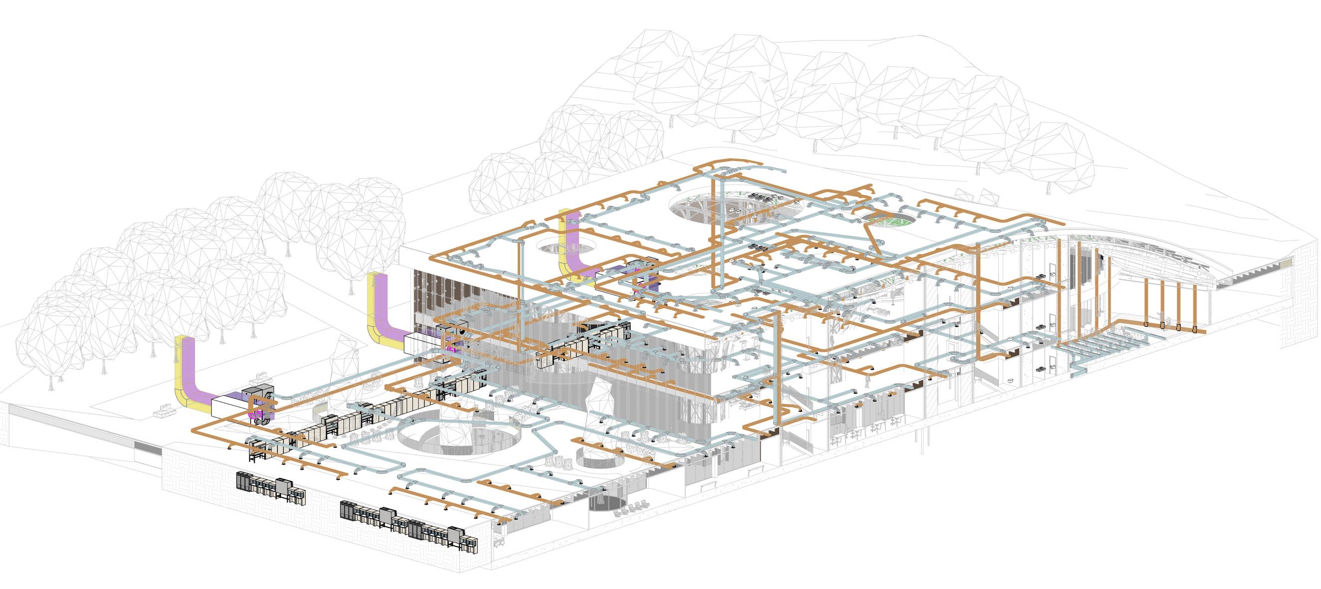

G H I 1615141312 J K 17 2 A104 1615141312 HEAAHU PUMP Air exhaust ducts maintanence zone Air Supply ducts nals Floor air terminals Delivery well Return well Outside air Return/Relief air 121 HVAC DUCT SYSTEM OVERALL VIEW HVAC DUCT SYSTEM conference hall Laboratory facilities Outside Air Retun/Releif air AHU unit Heat Pump
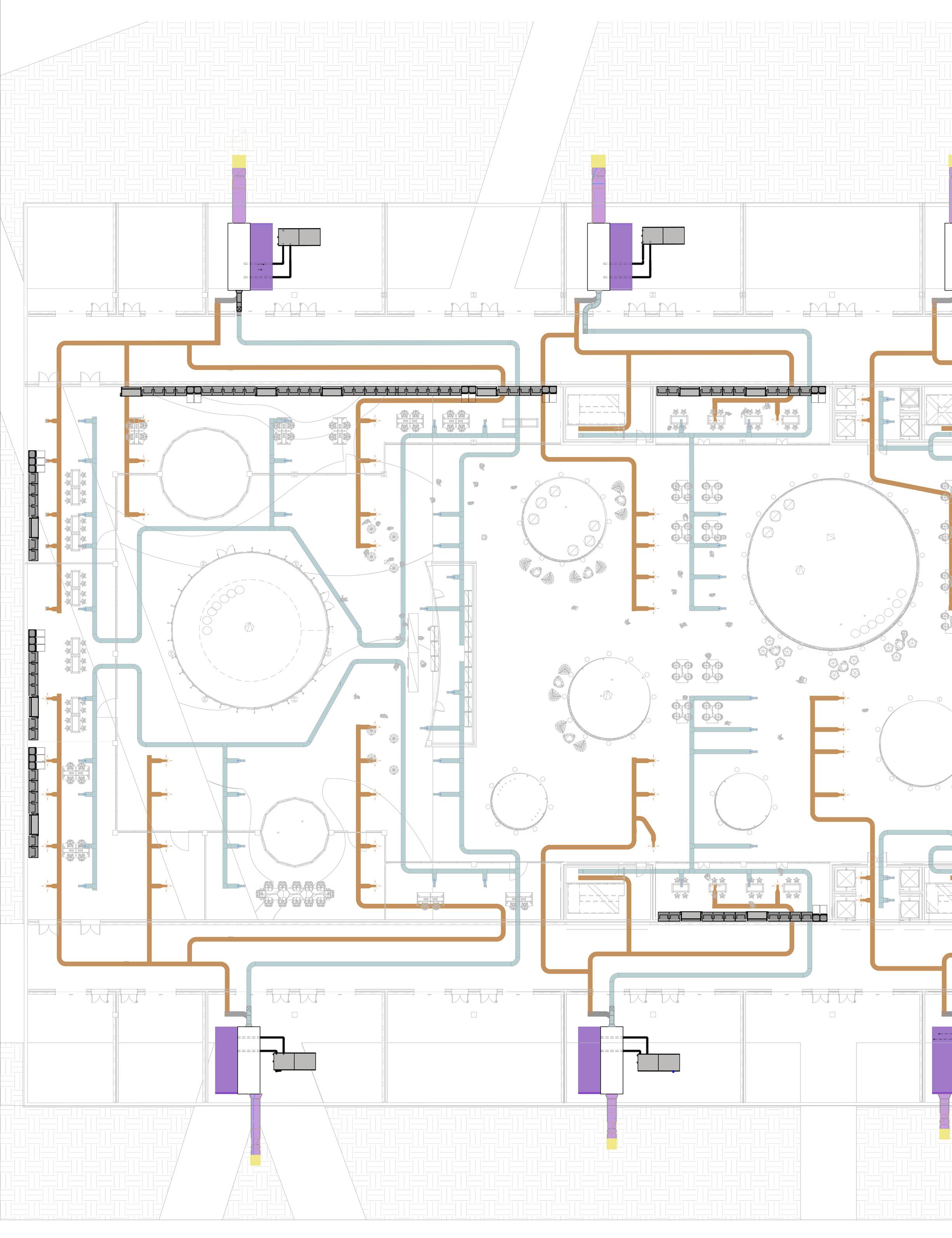
AHU AHUAHU AHUAHU Heat PumpHeat Pump Heat PumpHeat Pump Delivery wellReturn well Delivery well Return well Water supply room Water supply room Water supply room Water supply room NGM MILAN E.N 122
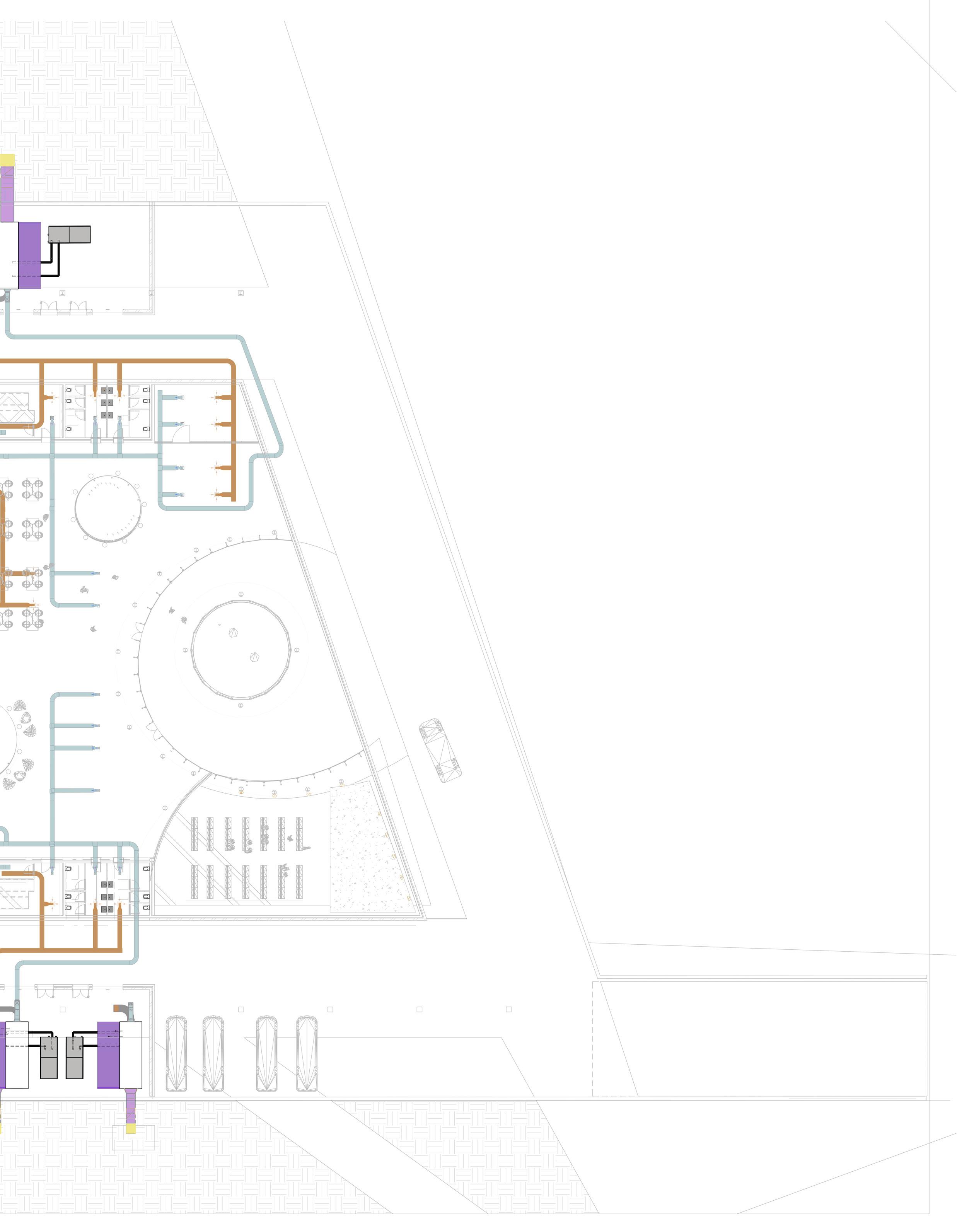
AHU AHU AHU Heat Pump Heat Pump well NGM MILAN 123
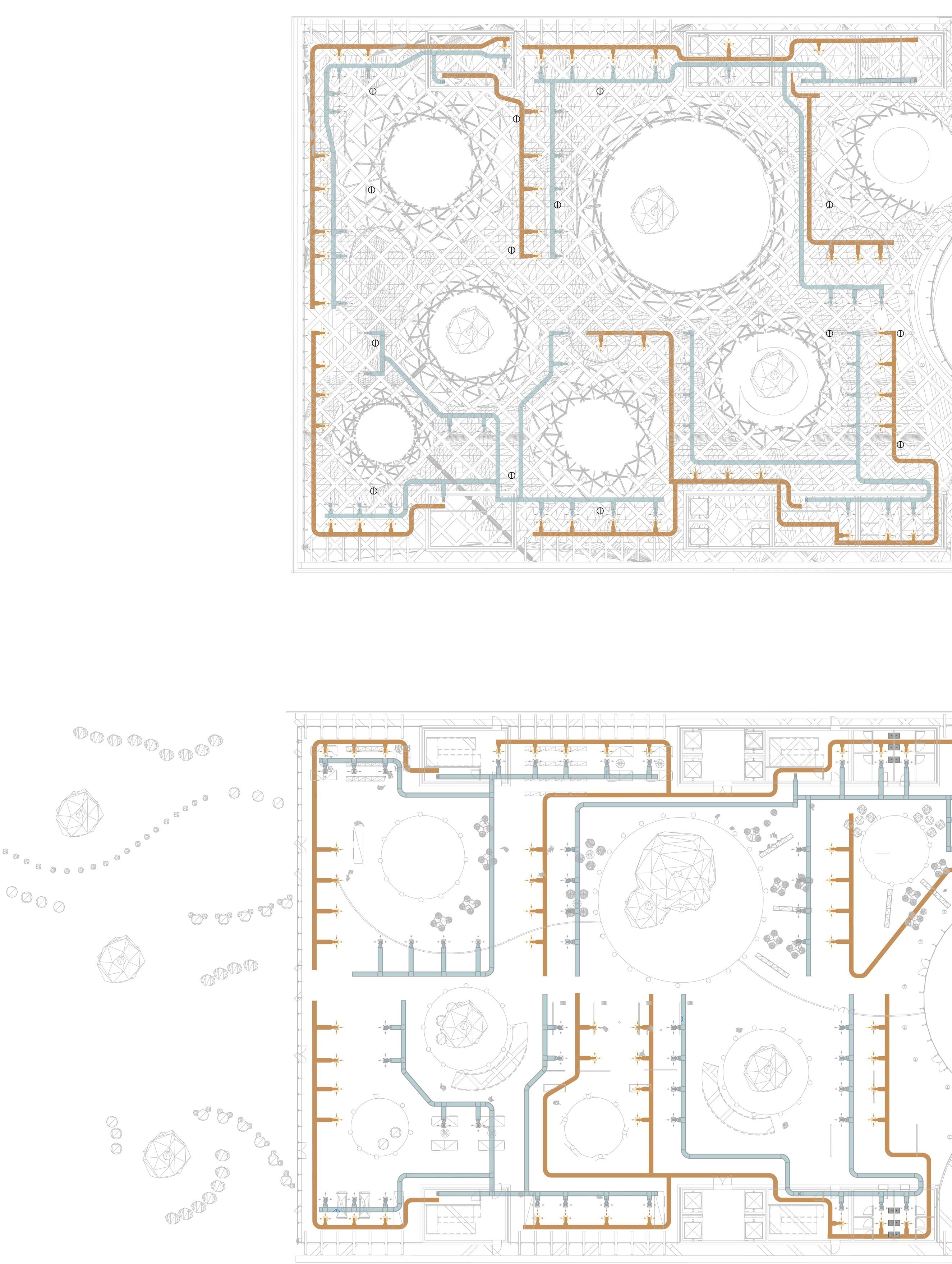
FIRST FLOOR CEILING 1:1000 GROUND FLOOR CEILING 1:1000 NGM MILAN E.N 124
HVAC SYSTEM
LEGEND
Air supply ducts
Air exhaust ducts
AHU unit maintanance area
AHU unit
Outside air ducts
Return/Relief air ducts
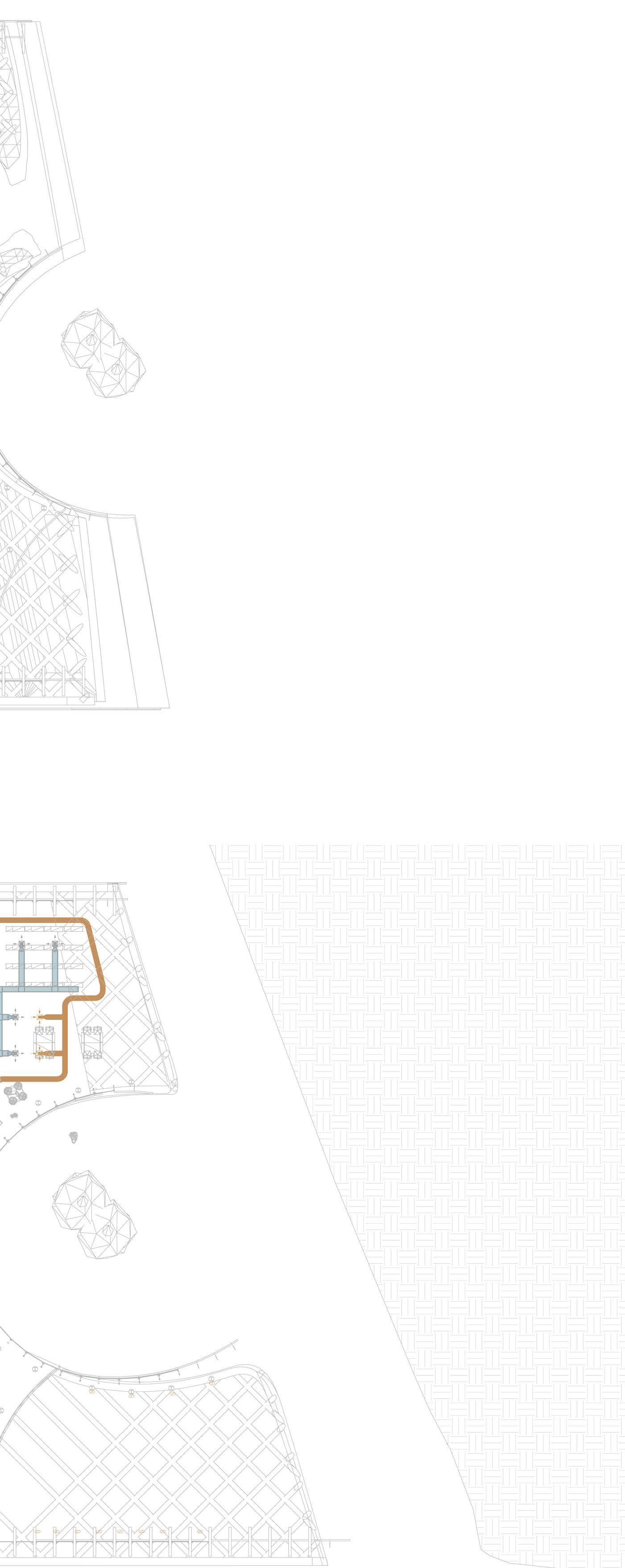
NGM MILAN 125
totem
INCORPORATING AIR DUCTS IN URBAN SPACES
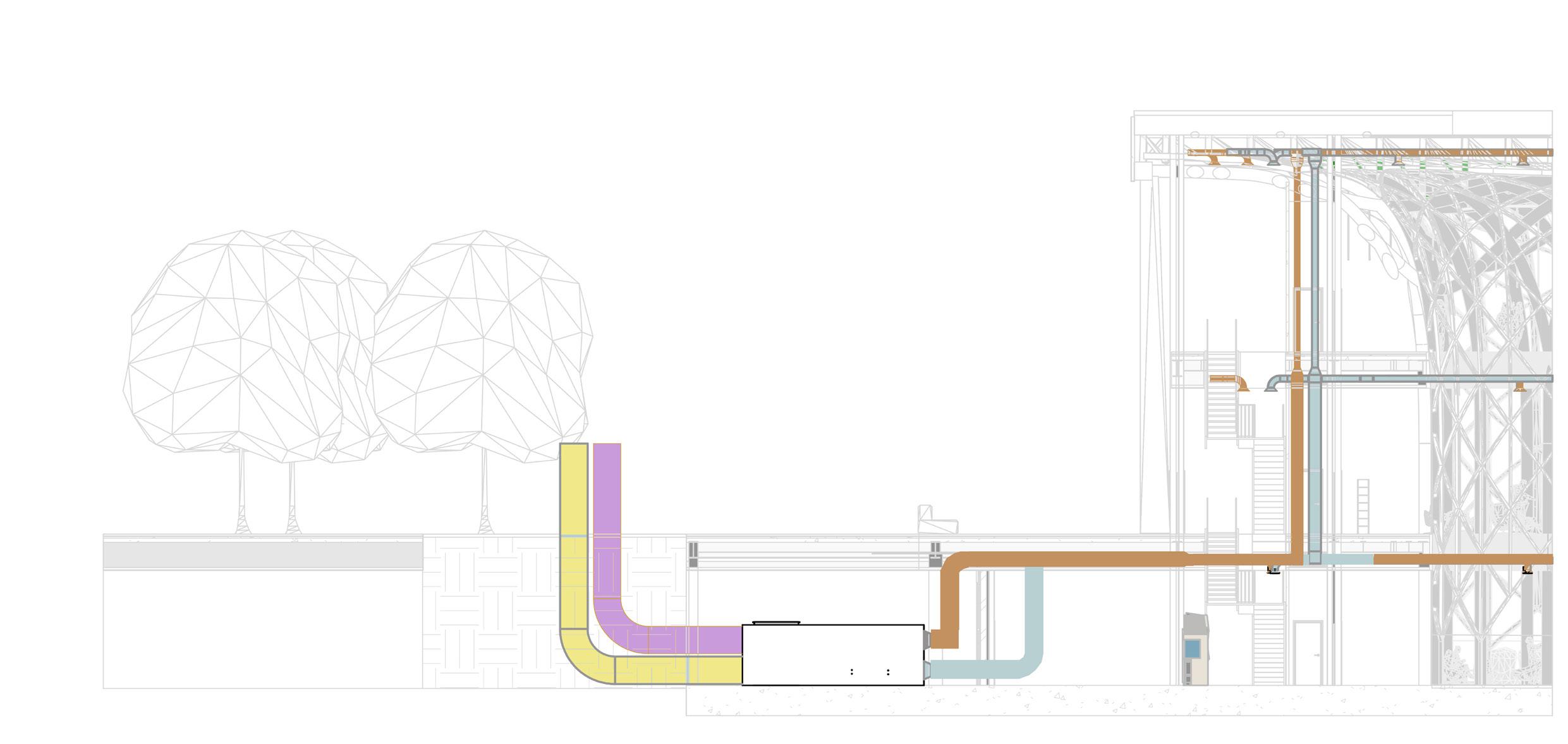
The HVAC system is completely underground, rather than on the roof, as is common in public buil dings. This was done for structu ral reasons concerning the loads on the parametric columns, in ad dition to aesthetic ones regarding the green roof being part of the green fabric. The decision, howe ver, prompted the requirement to separate/integrate the 3 m ducts rising from the undergro und within the context. The pro posed solution is to place ‚urban totems,’ vertical components that complement the surrounding ma terials and protect the ducts from rain and wind while yet enabling air to pass through. The totems are located around the building’s perimeter and serve as technolo gy hotspots throughout the park.
SMART TOTEMS
combining aesthetics and func tionality, the totems are able to provide services such as 5G connectivity, digital advertising, mobility communications, web access, info point, way-finding, emergency calls, payments, urban lightning, video surveillance and charging of electronic devices.
Air supply ducts
Air exhaust ducts
AHU unit maintanance area
AHU unit
Outside air ducts
Return/Relief air ducts
AHU unit Outside AirRetun/Releif air Smart
SECTION A-A’ 1:1000 NGM MILAN E.N 126
SERVICE DESIGN


SMART URBAN TOTEM


ST 3000 mm 1200 mm NGM MILAN 127
WATER SYSTEM
A portable water system for hu man consumption is made up of the following components:
1. Water networks, components, and equipment that enable the supply of water distribution of cold and hot wa ter from a building’s water outlets (supply).
2. Drainage, in the proportionate and necessary quantity to meet the needs of the final users.
The water system begins at the public potable water network’s supply point. (or private) and ends where water is utilized, at the sanitary applian ce.
WATER SUPPLY SYSTEM COMPONENTS:
1. System of supply.
2. The hot and cold systems, as well as the distribution network
3. System for producing hot water.
SERVICE DESIGN
COLD WATER SUPPLY
4. Main appliances and equip ment for end-of-life water distri bution.
Proper design of water-distribu tion system in a building is neces sary to avoid excessive installed cost and in order that the vario us fixtures may function proper ly under normal conditions. The correct design results in piping, water heating, the storage fa cilities of sufficient capacity to meet the probable peak demand without wasteful excess in either piping or maintenance cost.
**UNI 9182, UNI EN 806-part 1/5, and BS 8558:2015 are the technical standards.
NGM MILAN E.N 128
COLD WATER SUPPLY
A B C D ABCD(1) E F G EFGH(2) ABCDEFG(1+2)
LU tot 1 1 1 1 4 1 1 1 3 7
LU max 1 1 1 1 1 1 1 1 1 1 ds(mm) 16 16 16 16 16 16 16 16 16 20
H I J HIJ(3) 1+2+3 K L M N KLMN(4)
LU tot 1 1 1 3 10 1 1 1 1 4
LU max 1 1 1 1 1 1 1 1 1 1 ds(mm) 16 16 16 16 20 16 16 16 16 16
LU tot ds(mm)
A B C D ABCD(1) E F G EFGH(2) ABCDEFG(1+2)
LU tot 1 1 1 1 4 1 1 1 3 7
LU max 1 1 1 1 1 1 1 1 1 1 ds(mm) 16 16 16 16 16 16 16 16 16 20
H I J HIJ(3) 1+2+3 K L M N KLMN(4)
LU tot 1 1 1 3 10 1 1 1 1 4
LU max 1 1 1 1 1 1 1 1 1 1 ds(mm) 16 16 16 16 20 16 16 16 16 16
O A..N+O P
LU tot 1 15 1 16 LU max 1 1 1 ds(mm) 16 16 16 26
LU tot ds(mm)
A' B' A'B' C' A'B'C'
NGM MILAN 129
D' A'B'C'D' E' A'..E' LU tot 2 2 4 2 6 2 8 2 10 LU max 2 2 2 1 4 2 4 2 4 ds(mm) 16 16 16 16 16 16 16 16 20 Zone A ABCDRFGHIJKLMN(1+2+3+4) Bathroom and partially laboratories Zone A ABCDRFGHIJKLMNOP 16 26 W A T E R S U P P L Y C o l d s u p p l y Typical floor plan: First Floor and Ground floor C o l d s u p p l y Non-typical floor plan: Underground ABCDRFGHIJKLMN(1+2+3+4) 14 26 C o l d s u p p l y Non-typical floor plan: Underground Laboratory Zone B LU tot ds(mm) UL 14 14 16 LU tot 10 ds(mm) E F G EFG(1) H I J HIJ(2) 1+2 LU tot 1 1 1 3 1 1 1 3 6 LU max 1 1 1 1 1 1 1 1 10 20 Total Loading unit at the conjunction point of different branches: H o t s u p p l y Typical floor plan: First Floor and Ground floor 54 32 First floor Ground floor Under ground-zone A Under ground-zone B Zone A LU tot ds(mm) UL 14 14 16 LU tot 10 ds(mm) E F G EFG(1) H I J HIJ(2) 1+2 LU tot 1 1 1 3 1 1 1 3 6 LU max 1 1 1 1 1 1 1 1 10 20 Total Loading unit at the conjunction point of different branches: H o t s u p p l y Typical floor plan: First Floor and Ground floor 54 32 First floor Ground floor Under ground-zone A Under ground-zone B Zone A
SERVICE DESIGN
HOT WATER SUPPLY
Cold water pump
Hot water pump
Municipality water Supply connection
WATER SYSTEM DIAGRAM
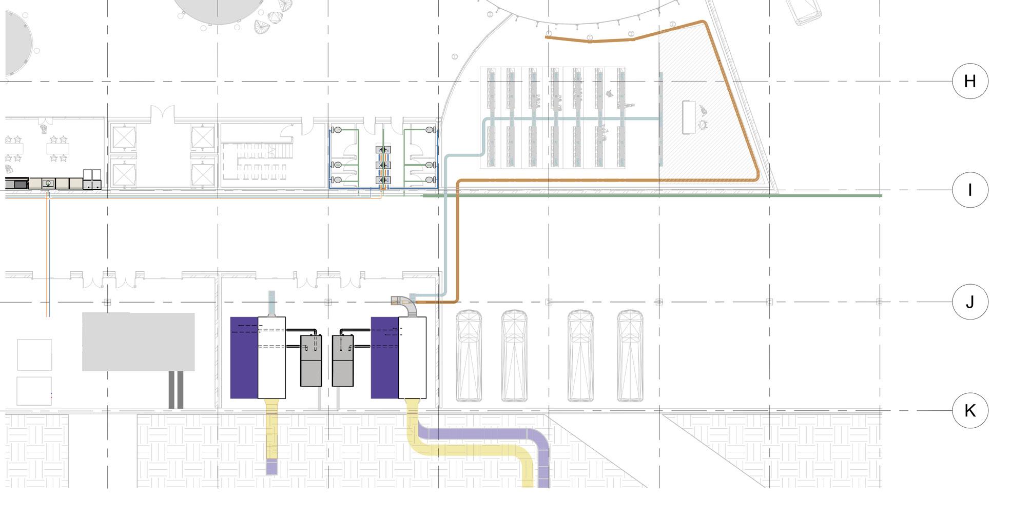
Air supply ducts
Air exhaust ducts
Hot water pipes
Cold water pipes
Cold water pipes
Discharge Stacks
NGM MILAN E.N 130
1312
Total
First floor
floor
ground-zone
E
Typical
tot ds(mm)
tot
max
ds(mm)
tot ds(mm)
ABCDRFGHIJ(1+2+3)
tot
max
ds(mm)
A'
T
NGM MILAN 131 HOT WATER SUPPLY UL 14 14 16 LU tot 10 ds(mm)
F G EFG(1) H I J HIJ(2) 1+2 LU tot 1 1 1 3 1 1 1 3 6 LU max 1 1 1 1 1 1 1 1 ds(mm) 16 16 16 16 16 16 16 16 18 LU
E F G EFG(1) H I J HIJ(2) O LU tot 1 1 1 3 1 1 1 3 2 8 LU max 1 1 1 1 1 1 1 1 3 3 ds(mm) 16 16 16 16 16 16 16 16 18 20 P E..P LU
2 10 LU
1 1
16 20 LU
B' A'B' C' A'B'C'(1) D' A'B'C'D' E' A'..E' LU
2 2 4 2 6 2 8 2 10 LU
2 2 2 1 4 2 4 2 4
16 16 16 16 16 16 16 16 20
Loading unit at the conjunction point of different branches: H o t s u p p l y
floor plan: First Floor and Ground floor 54 32
Ground
Under
A Under ground-zone B Zone A H o t s u p p l y Non-typical floor plan: Underground 10 20 Bathroom and partially laboratories Zone A
ABCDRFGHIJ(1+2) 6 18 H o t s u p p l y Non-typical floor plan: Underground Laboratory Zone B ABCDRFGHIJKLMN(1+2+3+4) A' B' A'B' C' A'B'C' D' A'B'C'D' E' A'..E' A'..E' DU(system I) 2 2 2 2 8 0.5 0.5 0.5 1.5 9.5 Frequent use ABCD= 8 K= 0.7 Qww= Qww=Qtot= 1.98 70/50 EFG= 1.5 K= 0.7 Qww= Qww=Qtot= 0.86 60/40 T o t a l = 9.5 K= 0.7 Qww= Qww=Qtot= 2.16 70/50 A1 B1 C1 D1 A1..D1 E1 F1 G1 E1..G1 Total DU(system I) 2 2 2 2 8 0.5 0.5 0.5 1.5 9.5 Ventilated/Discharge branches: Ventilated/Discharge branches: Ventilated/Discharge branches: >>The same will be considered for the male rest room. Usage of appliance: Zone A W A T E R D I S C H A R G E B l a c k w a t e r d i s c h a r g e Typical floor plan: First Floor and Ground floor(except souther one) >>In the underground there is a rest room beside meeting room S y s t e m t y p e : System II S y s t e m c o n f i g u r a t i o n : Primary ventilated system configurations W A
E R D I S C H A R G E B l a c k w a t e r d i s c h a r g e Non-typical floor plan: Underground Zone A
Water sanitary systems are com posed of:
1. Nets- components and ap pliances which let the intake and distribution of hot and cold water to the utilities of a building i (sup plying),
2. Drains- (sewer/plumbing, in the necessary quantity to satisy the utility (drainage).
WATER CLASSIFICATION:
Waste water-Water which is contaminated by use and all wa ter discharging into the drainage system; e.g. domestic and trade effluent, condensate water and also rainwater when discharged in a waste water drainage system.
Domestic waste water-Water which is contaminated by use and normally discharged from WC, shower, bath, bidet, wash basin, sink, floor gully.
Grey water- Waste water not containing faecal matter or urine.
SERVICE DESIGN
DRAINAGE SYSTEM
Black water-Waste water conta ining faecal matter or urine.
Rainwater-Water resulting from natural precipitation that has not been deliberately contaminated.
SYSTEM TYPE: SYSTEM II
Single discharge stack system with small bore discharge branch pipes. Sanitary appliances are connected to small bore branch discharge pipes. The small bore branch discharge pipes are desi gned with a filling degree of 0.7 (70%) And are connected to a single discharge stack.
NGM MILAN E.N 132
ABCD=
EFG= 1.5
T
Frequent use
W
ABCD=
9.5
Qww=Qtot=
0.7
Qww=Qtot= 2.16
Ventilated/Discharge
EFG= 1.5
Congested use
W A T E R D I S C H A R G E
Non-typical
Qww=Qtot=
W A T E R D
Non-typical
Ventilated/Discharge
R G E
NGM MILAN 133 DRAINAGE SYSTEM A' B' A'B' C' A'B'C' D' A'B'C'D' E' A'..E' A'..E' DU(system I) 2 2 2 2 8 0.5 0.5 0.5 1.5 9.5
8 K= 0.7 Qww= Qww=Qtot= 1.98 70/50
K= 0.7 Qww=
0.86 60/40
o t a l =
K=
Qww=
70/50 A1 B1 C1 D1 A1..D1 E1 F1 G1 E1..G1 Total DU(system I) 2 2 2 2 8 0.5 0.5 0.5 1.5 9.5
8 K= 1 Qww= Qww=Qtot= 2.83 80/50
K= 1 Qww=
1.22 60/40 T o t a l = 9.5 K= 1 Qww= Qww=Qtot= 3.08 80/50 A' B' C' D' A'..D' E' F G' E'..G' Total DU(system I) 0.5 0.5 0.5 0.5 2 0.5 0.5 0.5 1.5 3.5
branches: Ventilated/Discharge branches: Ventilated/Discharge branches: >>The same will be considered for the male rest room. Usage of appliance: Zone A
A T E R D I S C H A R G E B l a c k w a t e r d i s c h a r g e Typical floor plan: First Floor and Ground floor(except souther one) >>In the underground there is a rest room beside meeting room S y s t e m t y p e : System II S y s t e m c o n f i g u r a t i o n : Primary ventilated system configurations
B l a c k w a t e r d i s c h a r g e
floor plan: Underground Zone A Usage of appliance:
I S C H A
L a b o r a t o r y w a t e r d i s c h a r g e
floor plan: Underground Zone A
branches: Ventilated/Discharge branches: Ventilated/Discharge branches:
NGM MILAN E.N 134 T o t a l = 2 K= 1.2 Qww= Qww=Qtot= 1.70 70/50 Stack DU Stack DU 9.5 9.5 9.5 9.5 9.5 9.5 28.5 28.5 0.7 0.7 3.737 3.737 100/60 100/60 Stack DU Stack DU 5 3.5 6 2 3.5 2 1.2 1.2 8.2 5.2 Total Discharge unit at the conjunction point of different branches: Floor Ventilated/Discharge branches: 1 Floor First floor Ground floor Under ground2 Total k Qww k Qww Total First floor Ground floor Under groundDN DN DNDN k k Qww Qww Total Total Underground Underground Floor Floor >>The same for stack 3 and 4 5050
Air supply ducts
Air exhaust ducts
Hot water pipes
Cold water pipes
Cold water pipes
Discharge Stacks Drain
141312
NGM MILAN 135
BIBLIOGRAPHY
GENERAL
FRAMPTON, K. (1995) Studies in Tectonic Culture: The Poetics of Construction in Nineteenth and Twentieth Century Architecture, The MIT Press, Cambridge, Mass.
GREGOTTI, V. (1996), Inside architecture (translated by P. Wong, F. Zaccheo), Graham Foundation for Advanced Studies in the Fine Arts, The MIT Press, Cambridge, Massachusetts.
GREGOTTI V. (2010), Architecture, Means and Ends (translated by L.G. Cochrane, The University of Chicago Press.
MONEO R. (2004), Theoretical Anxiety and Design Strategies in the Work of Eight Contemporary Architects, The MIT Press, Cambridge, Massachusetts.
UNGERS, O.M., KOOLHAAS, R., RIEMANN, P., KOLLHOFF, H., OVASKA, A. (1978), Cities within the City, Sommer Akademie of Berlin by Cornell University. 1978.
BALMOND, C. (2002), Informal, Prestel Verlag, Munich- BerlinLondon-New York
DEPLAZES, A.(editor), (2008), Constructing Architecture: Materials, Processes, Structures: a Handbook, Birkhauser, Basel
GAUZIN-MULLER, D. (2002), Sustainable architecture and urbanism: concept, technologies, examples, Birkhauser, BaselBerlin-Boston
ZIMMERMANN, A. (2009), Constructing Landscape: Materials, Techniques, Structural components, Birkhauser, Basel
GONALVES, C., MARGARIDO, F., Materials for Construction and Civil Engineering (Science, Processing and Design), Springer, Berlino - Heidelberg
KHATIB, J.M. (2016), Sustainability of Construction Materials, Woodhead Publishing Series in Civil and Structural Engineering 70 (second edition)
LYONS, A. (2006), Materials for Architects and Builders, Butterworth-Heinemann, Oxford
In addition to the general bibliography, during the year further didactic supports and bibliographical indications will be supplied, about both lectures or seminars topics and specific issues examined by the students.
MILAN
MORANDI C. (2007), Milan. The Great Transformation, Milano.
LOTUS INTERNATIONAL MAGAZINE, monographic numbers: Milano Boom (n.131, 2007), Meteo Milano (n. 161, 2016).
ANDREOLA, I., BIRAGHI, M., LO RICCO, G. (2015), Milan architectural guide 1945-2015, Hoepli, Milano
BERIZZI, C. (2015), Milan: buildings and projects since 1919, DOM, Berlin
MIND MILANO INNOVATION DISTRICT https://www.arexpo.it/en/ homepage https://www.mindmilano.it/en/ https://www.htechnopole.it/en/ campus https://www.mindmilano.it/ en/human-technopole-newbuilding/ https://fondazionetriulza.org/ cose-cascina-triulza/
CRA – CARLO RATTI ASSOCIATI (2018), Science for Citizens. The Science Campus of the University of Milan in MIND (Schematic Design)
NGM MILAN E.N 136
the transformation of Milan’s former 2015 World Expo site
https://carloratti.com/project/ milans-science-knowledge-andinnovation-park/ Università degli Studi di Milano – The new University Campus in Mind
https://www.unimi.it/en/ university/la-statale/ourheritage-our-future/campusproject
https://web.comune. milano.it/wps/portal/ PubblicazioniUrbanistiche/ archivio_pubblicazioni_ urbanistiche_2019/ pii+mind+adozione2
International Design Competition “Human Technopole: the new Headquarters” for the design of the new headquarters of Fondazione HT, located in MIND – Milano Innovation District
KATZ, BRUCE, WAGNER JULIE, The Rise of Innovation Districts: A New Geography of Innovation in America, Metropolitan Policy Program at Brookings
MIT SCHOOL OF ARCHITECTURE AND PLANNING (2011), Innovation Technology Innovation Park. A research Study: Nandasoft Innovation Technology Development Park, Massachusetts Institute of Technology School of Architecture and Planning, Cambridge
MOODYSSON, J., & JONSSON, O. (2007), Knowledge collaboration and proximity the spatial organization of biotech innovation projects. European
urban and regional studies, 14(2), 115-131.
RUSSELL, J. S. (1992), The New Workplace, Architectural Record, June 1992, p72
LAB OF THE FUTURE
FISHMAN, M. C., (2017), LAB – Building a Home for Scientists, Lars Müller Publishers GmbH, Zurich
GOLDSTEIN, R. N. (2006), Architectural Design and the Collaborative Research Environment, Cell 2006 Oct 20, 127(2), 243-6.
HARRISON, A. L., SERRA, M., (2011) Learning from Laboratories, in Log N°21 (WINTER 2011), Anyone Corporation, PP. 53-61 (http://www.jstor.org/ stable/41765397)
KLONCK, C. (2016), New Laboratories: Historical and Critical Perspectives on Contemporary Developments, De Gruyter, Digital original edition (April 11, 2016)
WATCH, D. D., KLIMENT, S.A., PERKINS & WILL, (2008), Building Types Basic For Research Laboratories, John Wiley & Sons, Inc. https://www. laboratoryequipment.com/
NEUMAN, D. J. (2013), Building type basics for college and university facilities (2nd edition),
Wiley, Hoboken (2018) Complex buildings, Learning system, A+T: Revista de arquitectura y tecnologia, Issue 50, 2018
STRUCTURAL DESIGN
Case study: Sendai Mediatheque, Sendai, Japan,Toyo Ito , 1995-2001, built area 2,844 m².
Sendai Mediatheque references:
Publication excerpt from The Museum of Modern Art, MoMA, Highlights since 1980, New York: The Museum of Modern Art, p. 197
Pritzker Prize 2013 Biography http://architectuul.com/ architecture/sendaimediatheque https://en.wikiarquitectura. com/building/sendaimediatheque/ https://www.smt.jp/ https://divisare.com/ https://www.archiweb.cz/ https://www.marcus-paul.com/ sendai
COLUMNS ENVELOPE
FOSTER, NORMAN,(2001) Norman Foster and the British Museum, Munich : New York : Prestel.
FOSTER AND PARTNERS,(2019), The red sea airport,Saudi arabia, Project documentations.
NGM MILAN 137
NGM MILAN E.N 138 Politecnico di Milano School of civil architecture AA 2020/2022