PORTFOLIO


 EDEN NIMNI

eden.nimni@mail.polimi.it
EDEN NIMNI

POLITECNICO DI MILANO
School of Architcture Unban Planing Construction Engineering Architectural design AA 2017-2022

20.09.1993
PERSONAL| INFORMATION
EDUCATION|2012-2022
17/10/2020-6/10/2022
Master of science degree in building architecture at politecnico di milano,Italy
22/07/2020
Bachelor of science degree in architectural design at politecnico di milano
Thesis: thematic portfolio. ‘Socially sustainable urban regeneration’ * mark 103/110
10/2015-10/2016
Architecture and design studies at the university of Tel aviv. * mark 90/100
2012
Diploma: foreign high school at multidisciplinary high school of yehud (yehud - israel)Mark 95/100
PERSONAL INFO
Born in Tel-Aviv, Isreal, 20/09/1993
Current Address: Via Giovanni Pacini 11,Milan 20131.
Mobile Nr.: +393476760235
Email: eden.nimni@mail.polimi.it
Citizenship: ISRAELI
Residence: Milan
INTERNSHIP AND WORK EXPERIENCE|2019-2021
03/2020-06/2020
Internship - Hava G. architects, Israel
9/2020-01/2021
Render design- Adrad Architects ,Tel aviv, Israel
1/2022-2/2022
Internship - Gruppo SPA Milan,Italy.
CHOSEN ACADEMIC PROJECTS
TALPIDEA | mixed use building
An urban farm conceptual design in Istanbul
LIVING LANDSCAPE,SICILY IT | Urban revival
The New community of Salemi – reviving the city of Salemi
INSIDE-OUT HUB, MILAN,ITALY| Flexible office spaces
Transforming an abandoned property in Mi lan to a mixed used.
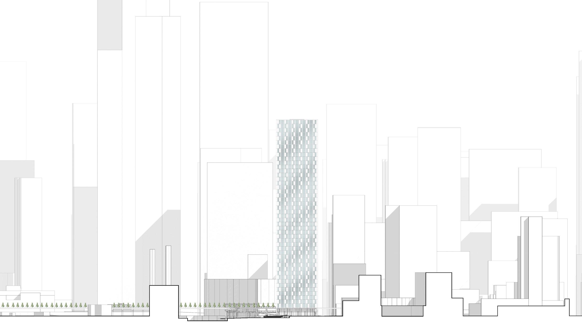
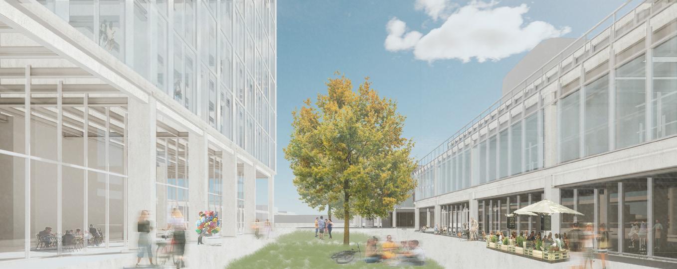
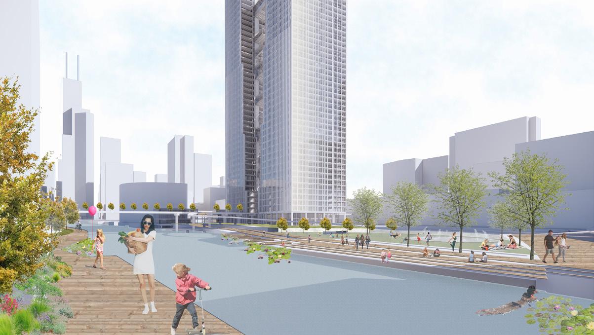
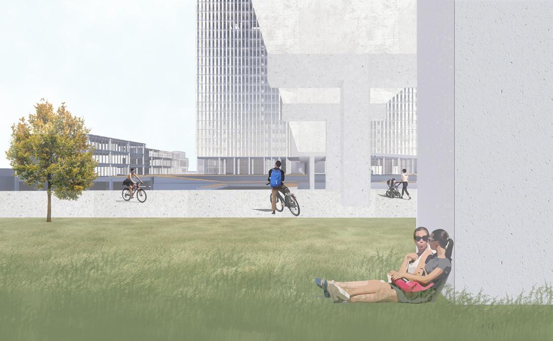
THE SPLIT, CHICAGO IL| Residential skyscraper
A strategic approuch of Reinforcing a histori cal junction
NGM, MIND MILAN| Museum/Research center
A new gate developed for Mind disctirc, Milan.
CONTENT| INDEX
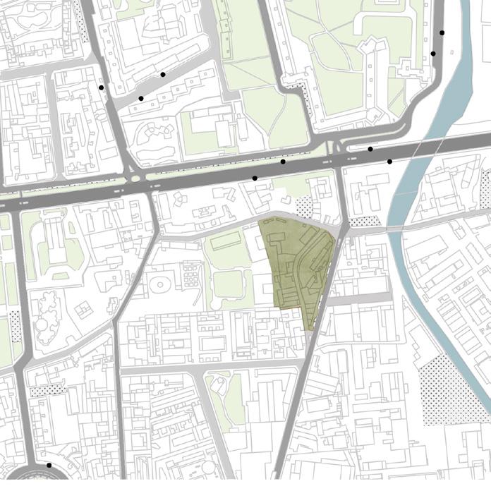
TALPIDEA
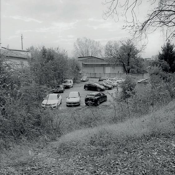
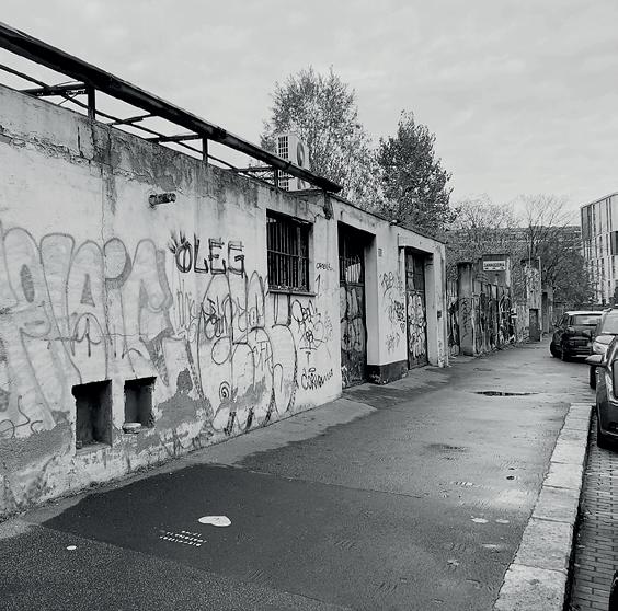
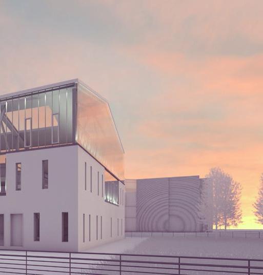
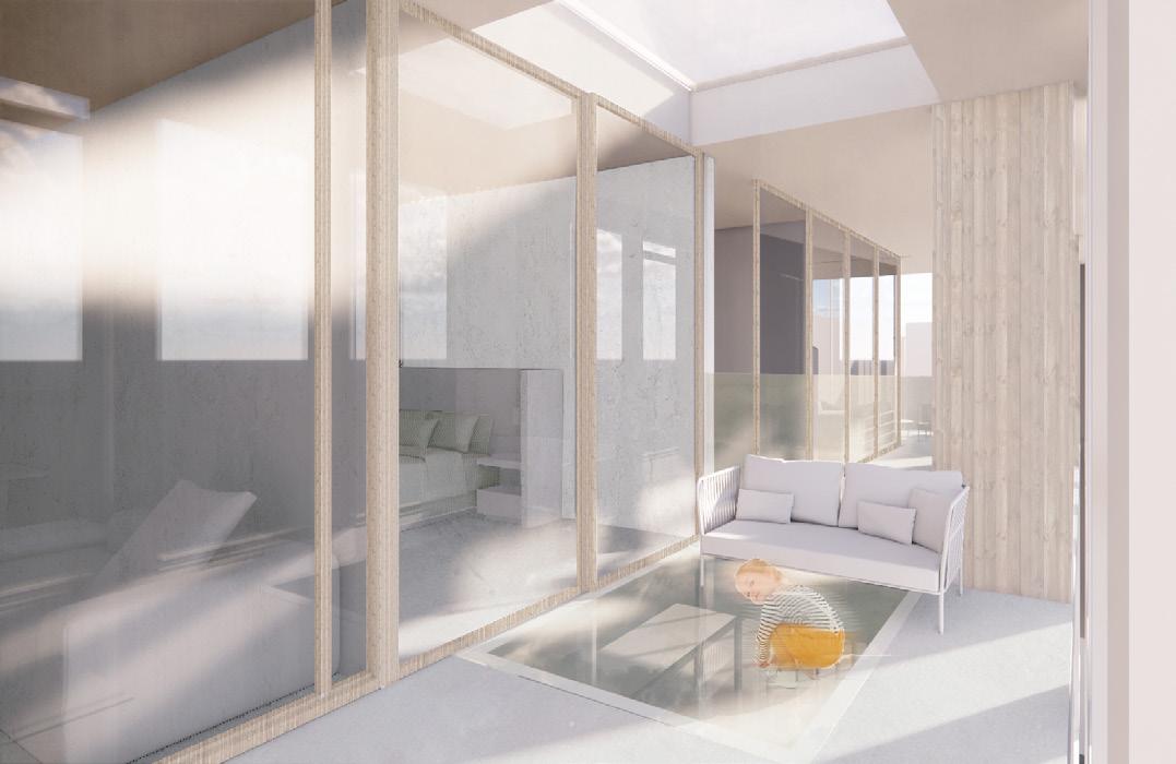
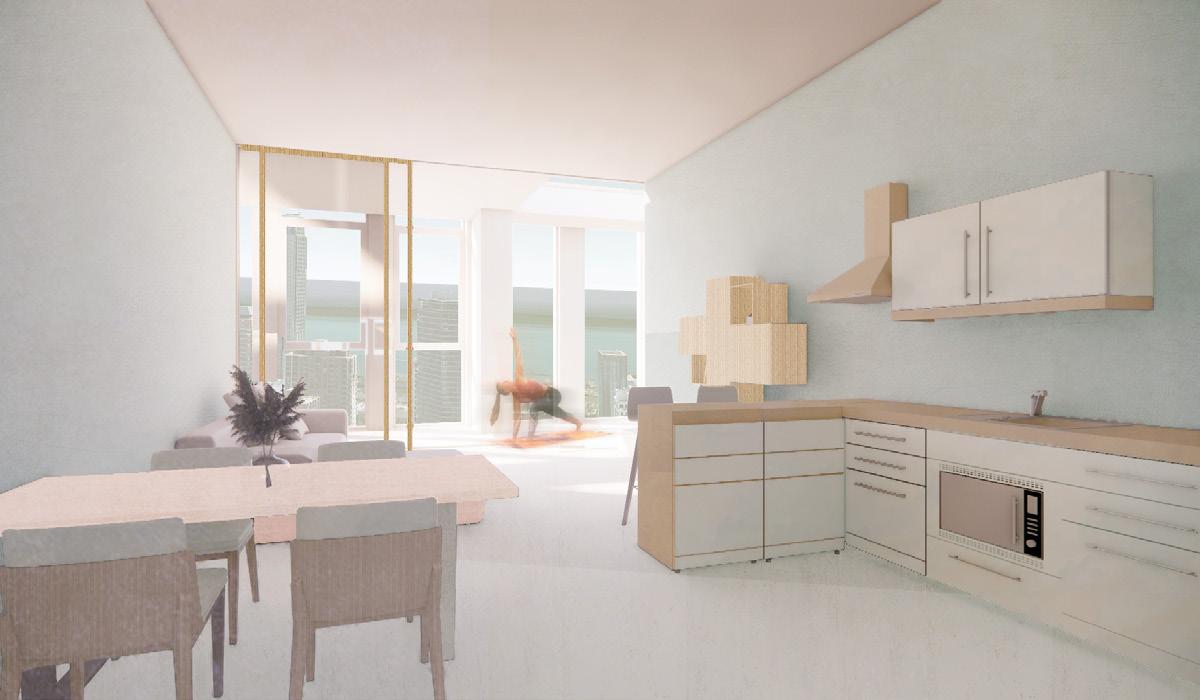
Located in the Lambrate district of Milan, Talpidea is a mixed-use complex overlooking an un derground market. With its diverse typologies, it combines both luxurious and affordable apartments. It is then adapted to a modern social approach by integrating different popu lations through the various commercial functions: market, coworking space, gym, artigenial shops and a park.
ROAD
Important connection: SP103 - External Ring Road, connects Lambrate to the rest of the city
METROPOLITAN
Important connection: LambrateLoreto, connects to other metropolitan lines
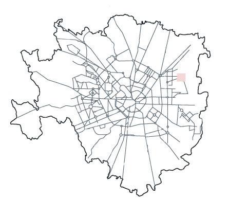
RAILWAY
Important connection: LambrateCentrale, central
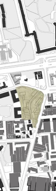
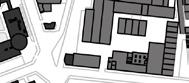
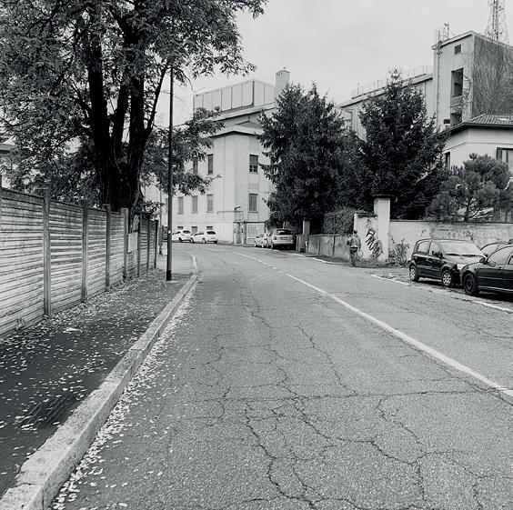
PROJECT AREA- VIA ROMBON Existing abandoned property, for mer factory.
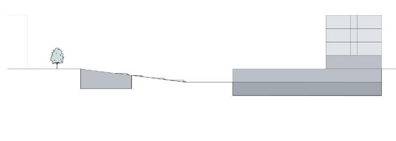
TYPOLOGY ANALYSIS
industrial VS residential and other functions.
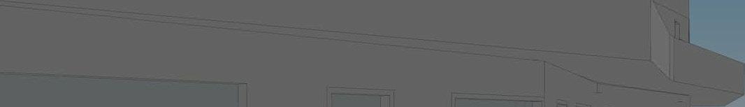
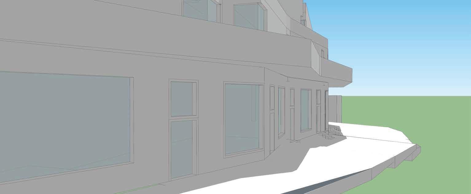
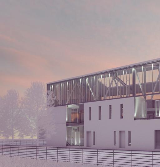
North-east view
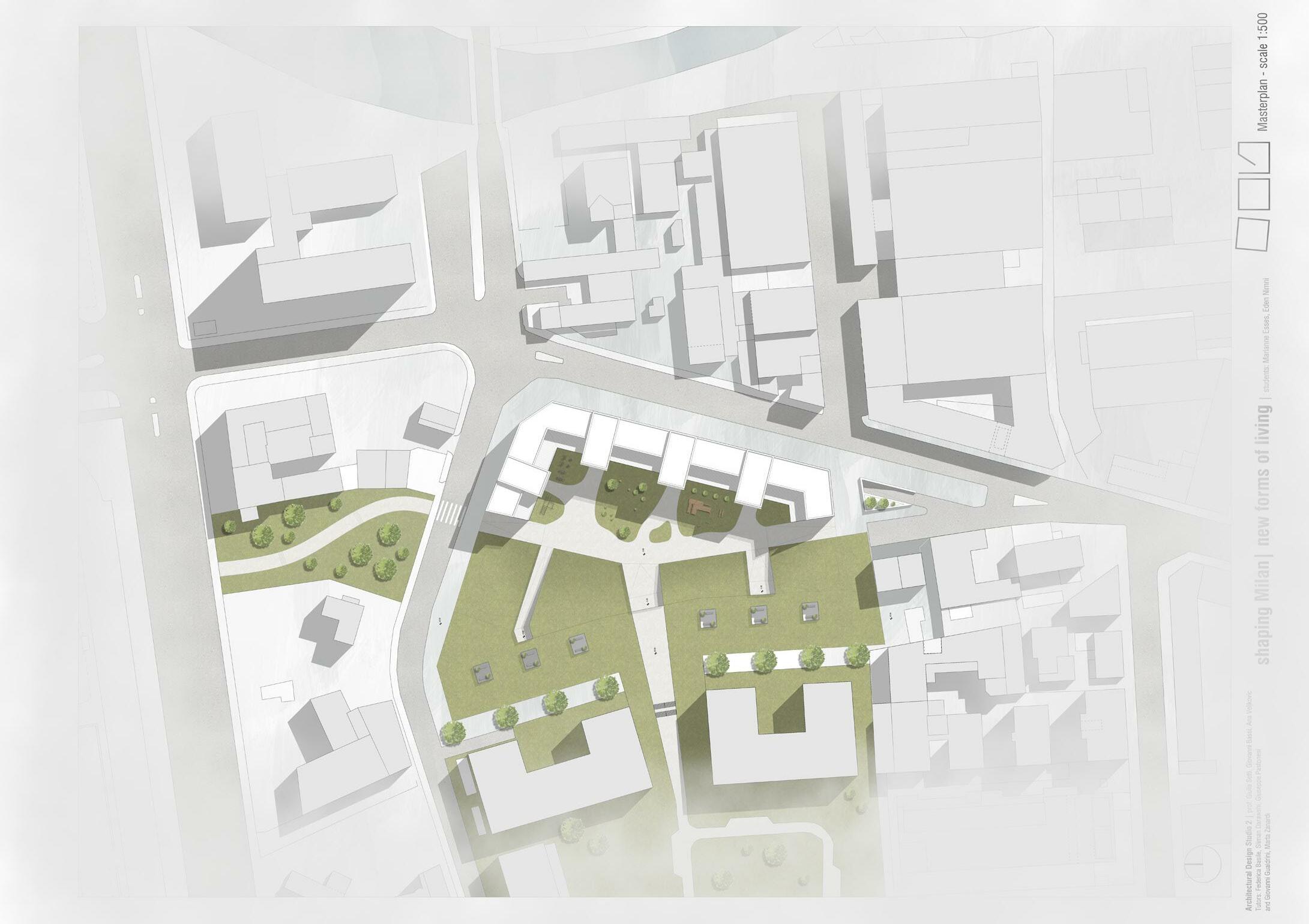
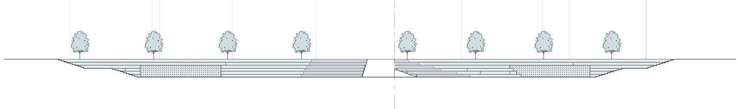
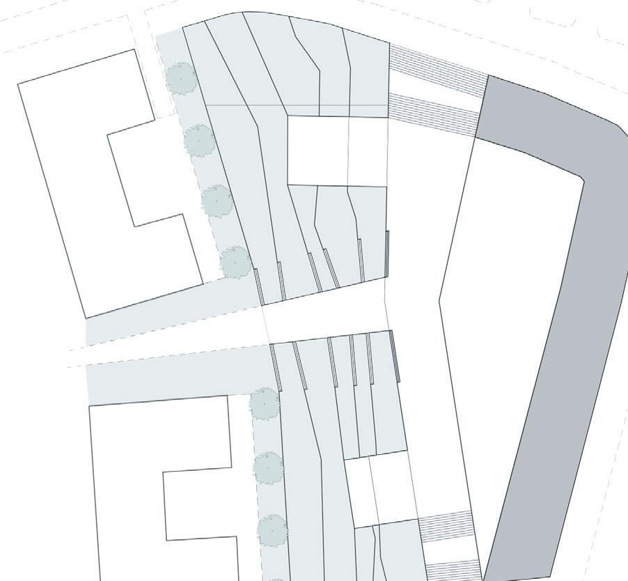
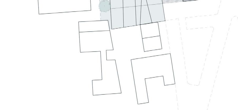
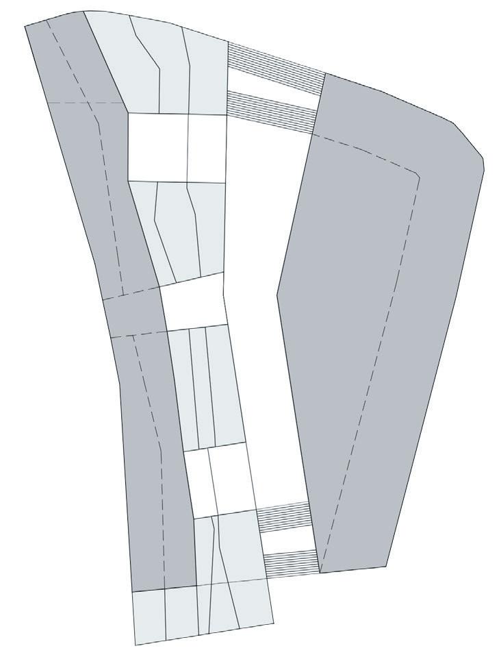
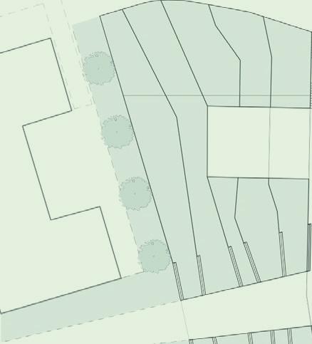
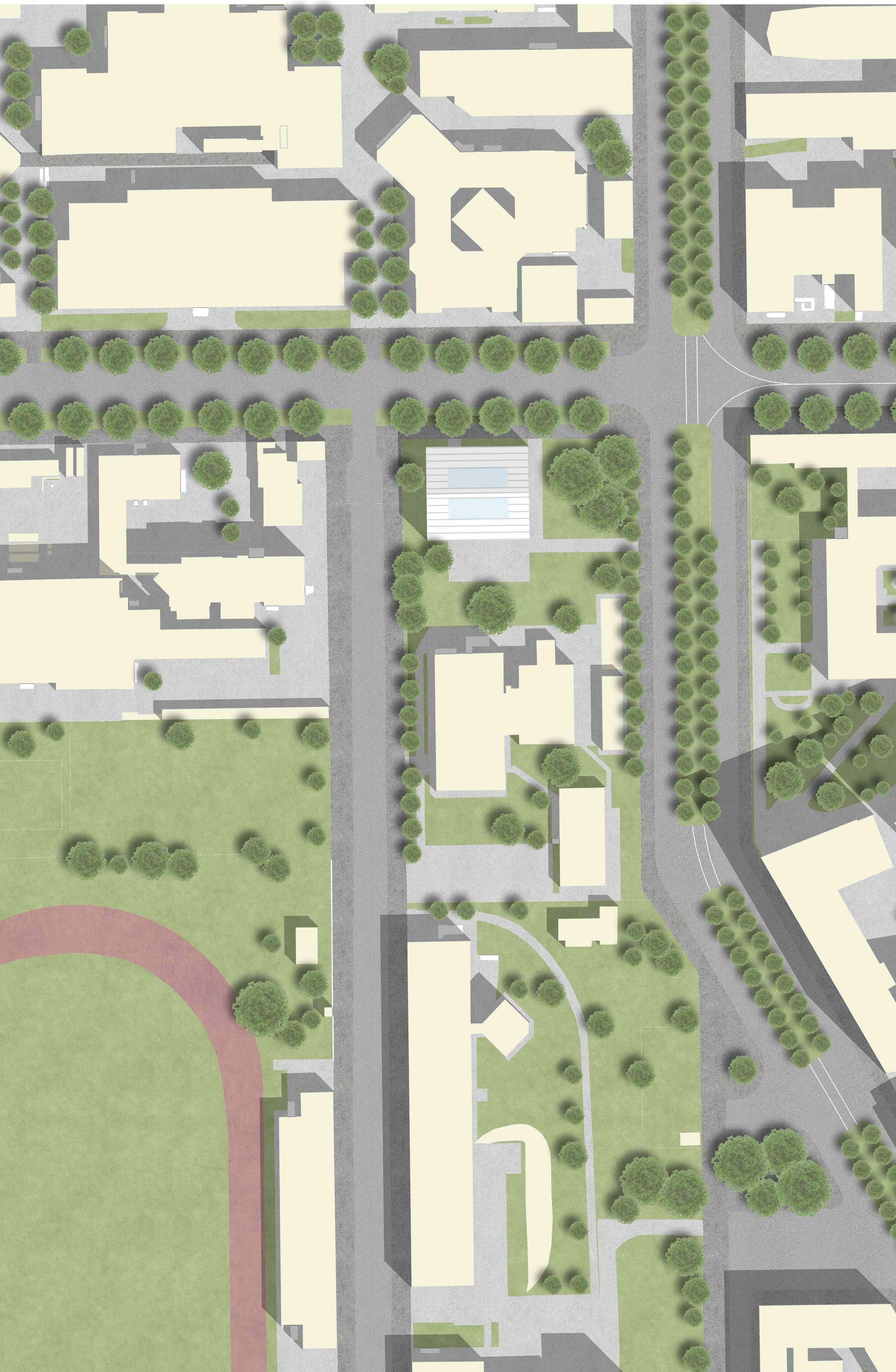
THE MASTERPLAN represents the visual connection to the main road , Rombon street, the arrangement of the new pathways and crossroads provide a safer access to the residential area from the main road and a more approachable atmosphere.
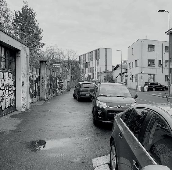
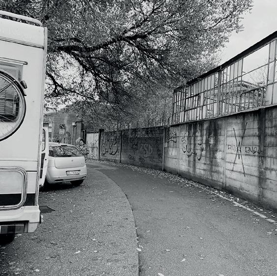
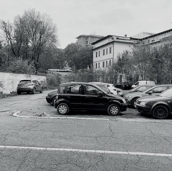
South-east view photographic survay

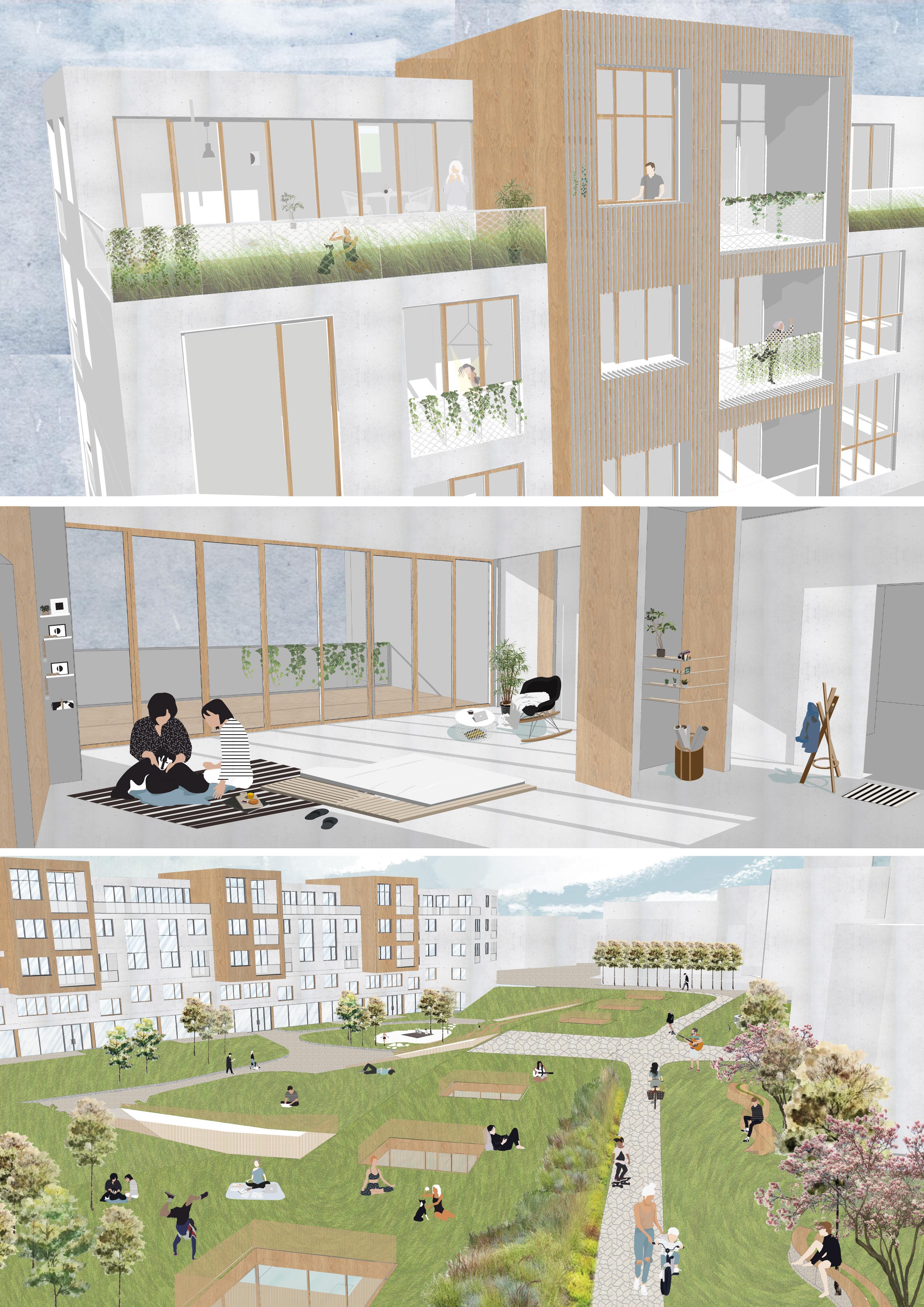

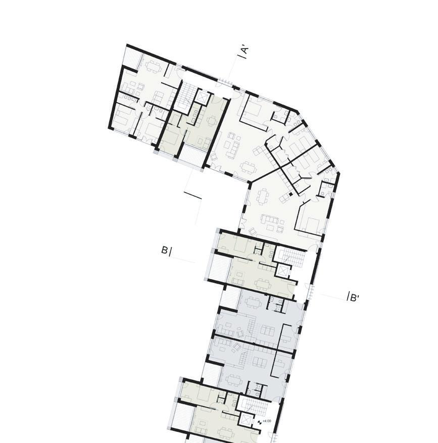
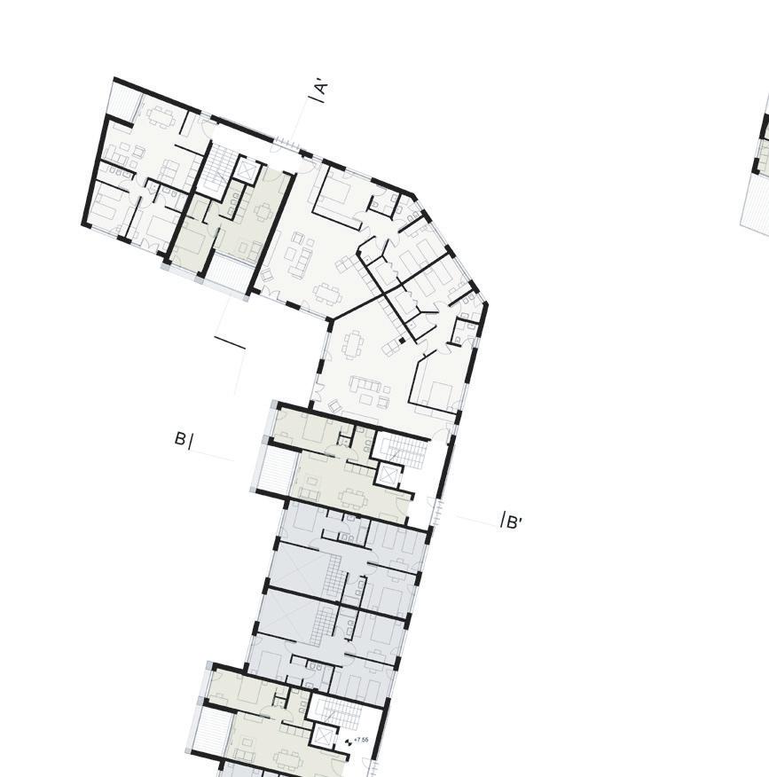
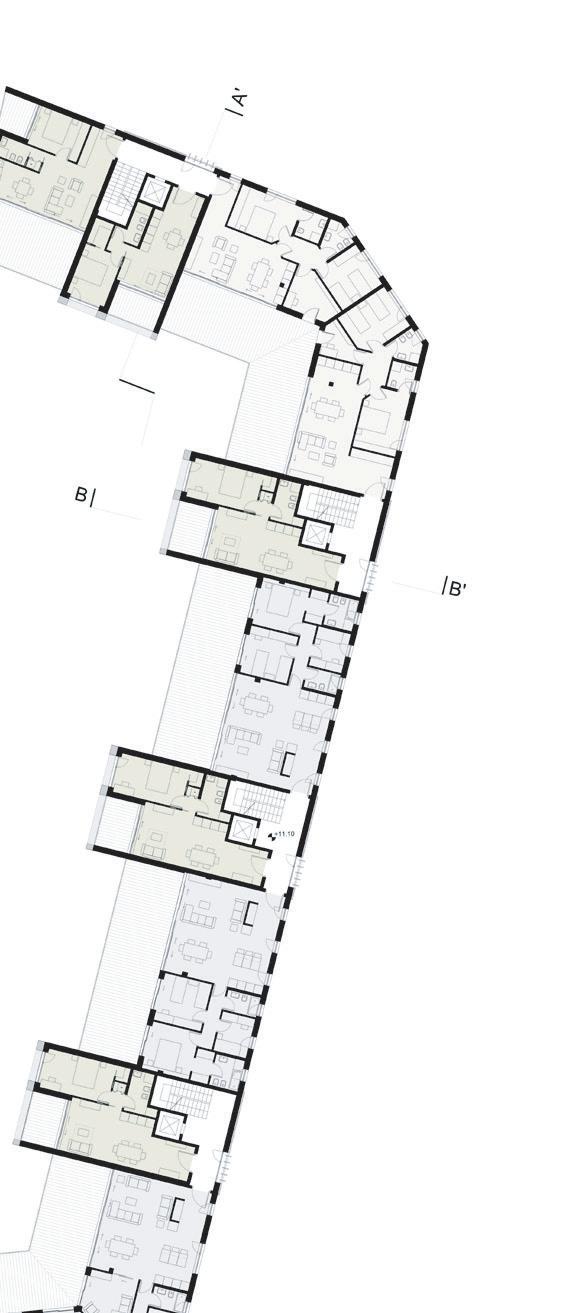
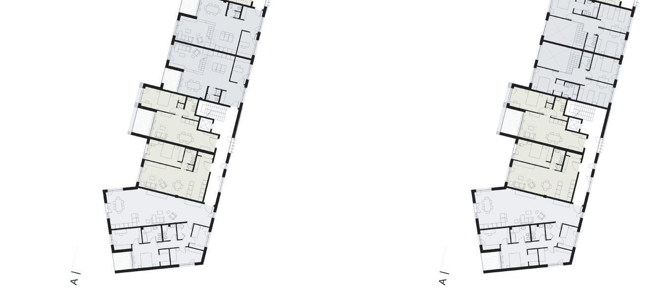
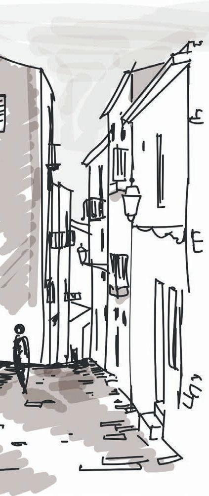
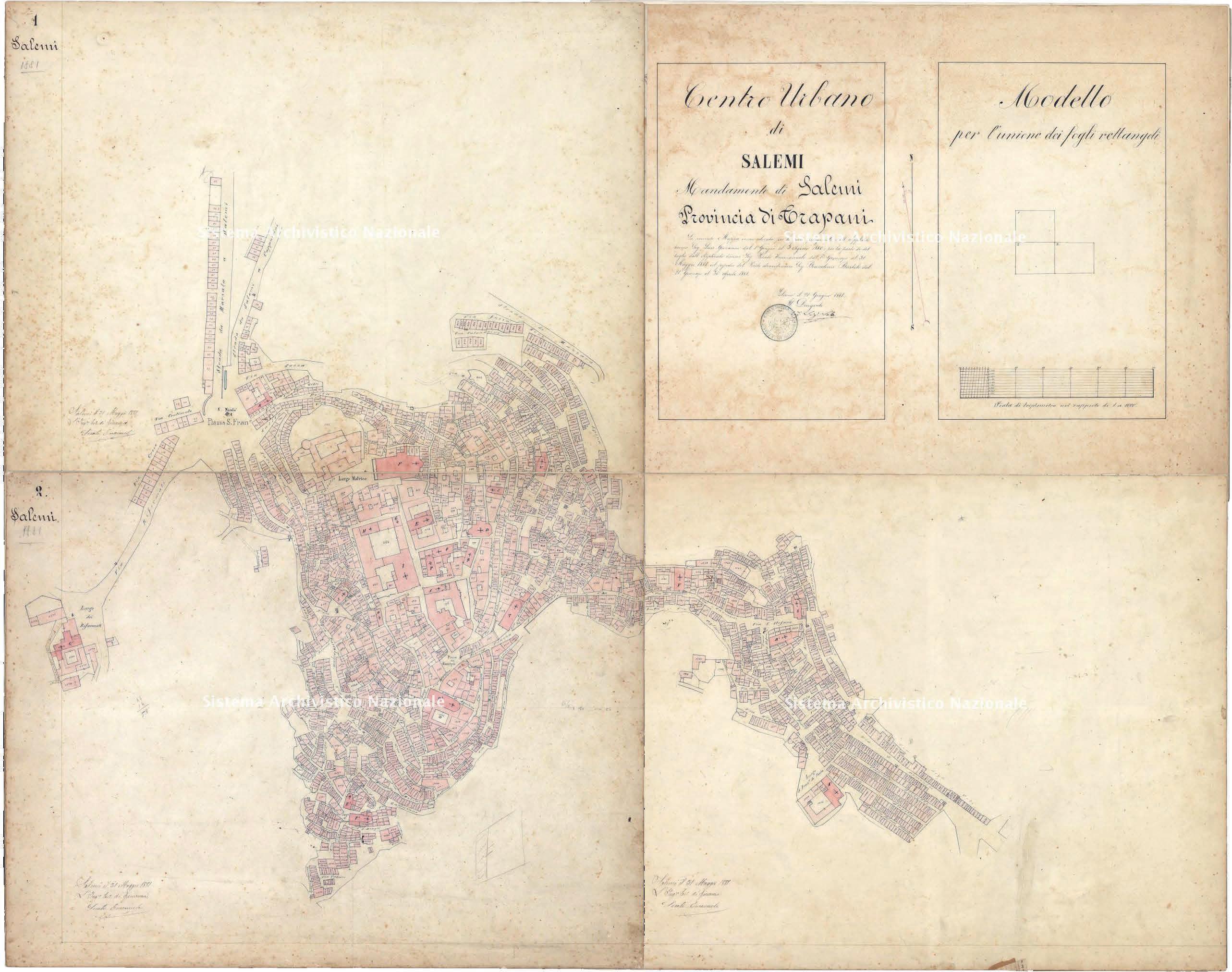
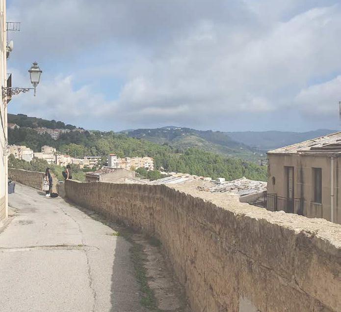
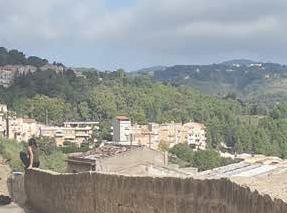
The New community of Salemi
Reviving the city of Salemi by attracting a new residence to live in a city which offers a self-sustainable agriculture system and new functions and opportunities while maintaining the pro per respect toward the existing community and heritage. The project deals with social, moral, and historical issues. Visiting the site, discussing with the locals and the mayor, we have studied the city, trying to understand the social needs and li sten to the main dysfunctionalities. With both our own know ledge and the use of different resources and bibliographies, we developed the urban regeneration strategy which in our opinion suited the situation in Salemi.
Piazza Liberta
Piazza Alicia Castello Normano
Jewish quarter


Teatro del Carmine
Piazza Dittitura Comune di Salemi
Ex.
chiesa madre di Salemi Chiesa della conceaionePolo Museale Mafia museum bread museum
14 15 Analythical maps Built Not built Part 2: The attraction of the specific site well conserved or reconstructed public streets gardens courtyards soil of ruins damaged with roofs damaged without roof totally ruined State of conservation of buildings Materials of the ground Part 2: The attraction of the specific site 14 15 Part 2: The attraction of the specific site well conserved or reconstructed public streets gardens courtyards soil of ruins damaged with roofs damaged without roof totally ruined State of conservation of buildings Materials of the ground Part 2: The attraction of the specific site
The Masterplan
The design proposal has developed as a way to frame the views of Salemi provi ding a picturesque promenade along fields of terraced vineyards. Combining old and modern, using the unique and diverse topography of the site, defining a divi sion between private and public outdoor spaces.creating two main piazzas with diverse functions injected in public buildings which follow the traces of the ruins. Two residential buildings are located in the middle of the complex in between the two public piazzas assuring a high level of accessibility. They are connected by a common semi-private courtyard working as the social core of the community.


INSIDE-OUT HUB, MILAN,ITALY| Flexible office spaces
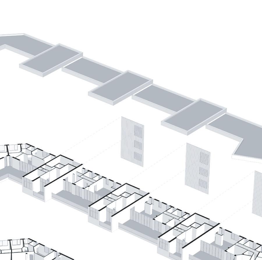
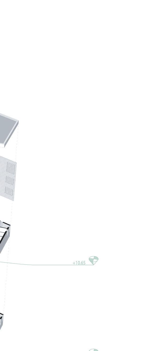
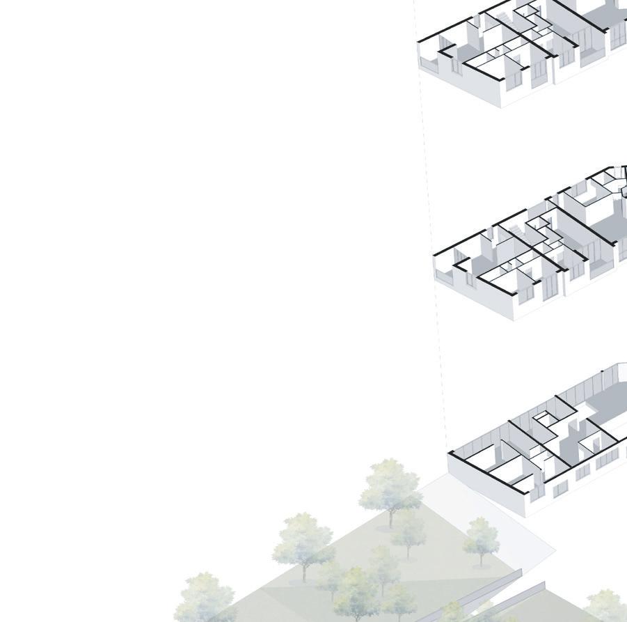
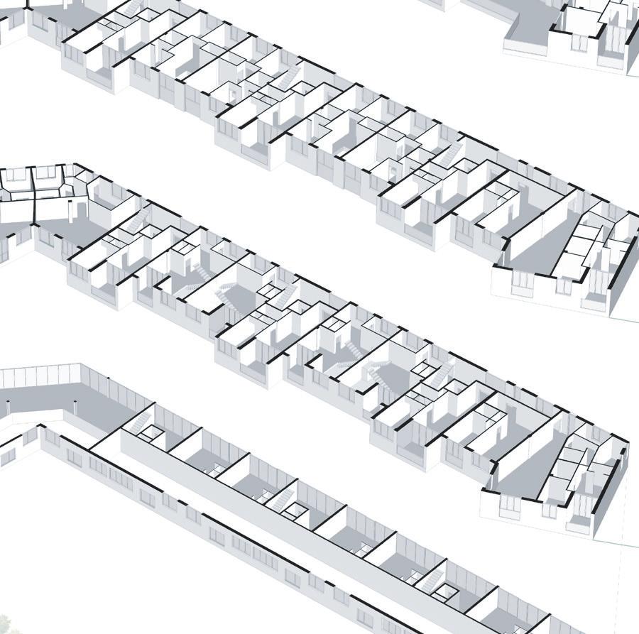
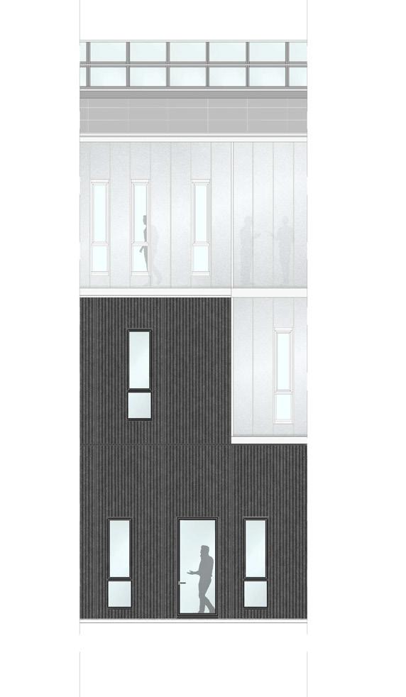
School of Architecture, Urban Planning and Construction Engineering Architecture Construction Studio panel: FLOOR PLANS 1:100 3AGreta Cornaggia Eden Nimni 967144 Paolo Carlesso Manuel Garramone scale: GROUND FLOOR PLAN 1:100 FIRST FLOOR PLAN 1:100 Marco Scaioni2020-2021 Architecture Construction Studio FLOOR PLAN AND ROOF PLAN 1:100 3B Eliana Tonelli SECOND FLOOR PLAN 1:100 ROOF PLAN 1:100 Politecnico di Milano School of Architecture, Urban Planning and Construction Engineering Architecture Construction Studio ELEVATIONS 1:100 4Greta Cornaggia Iva Miteva 966705 05/02/2021 Imane El Bakkali 961849 Marianne Esses 967775 Eden Nimni 967144 Paolo Carlesso NORTH FACADE ELEVATION EAST FACADE ELEVATION
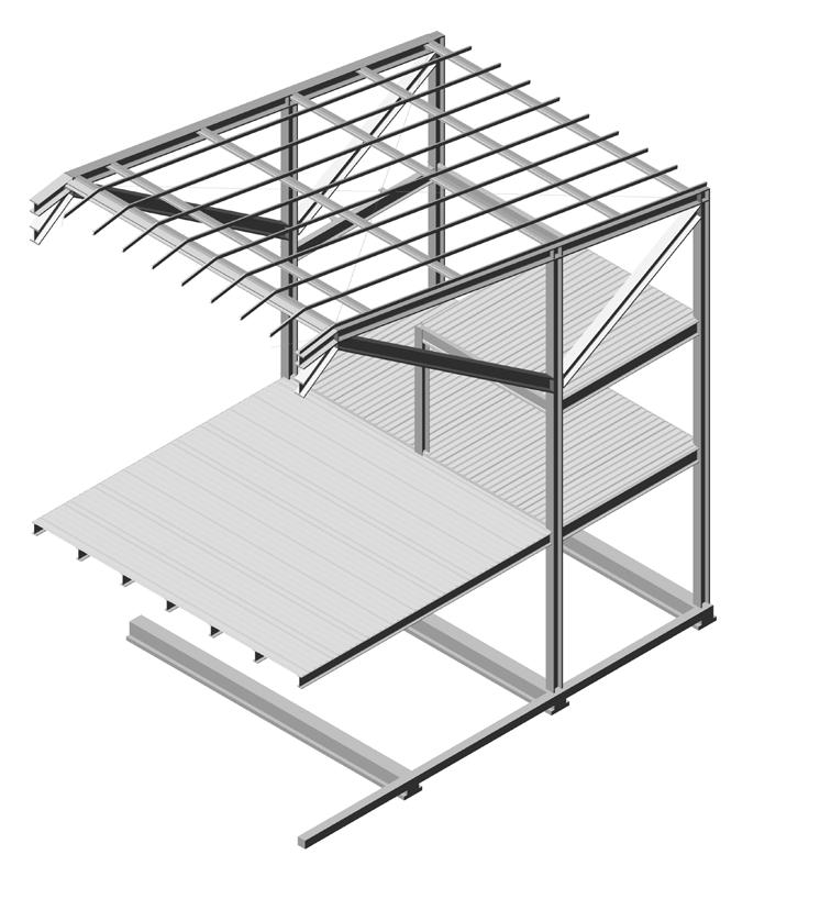
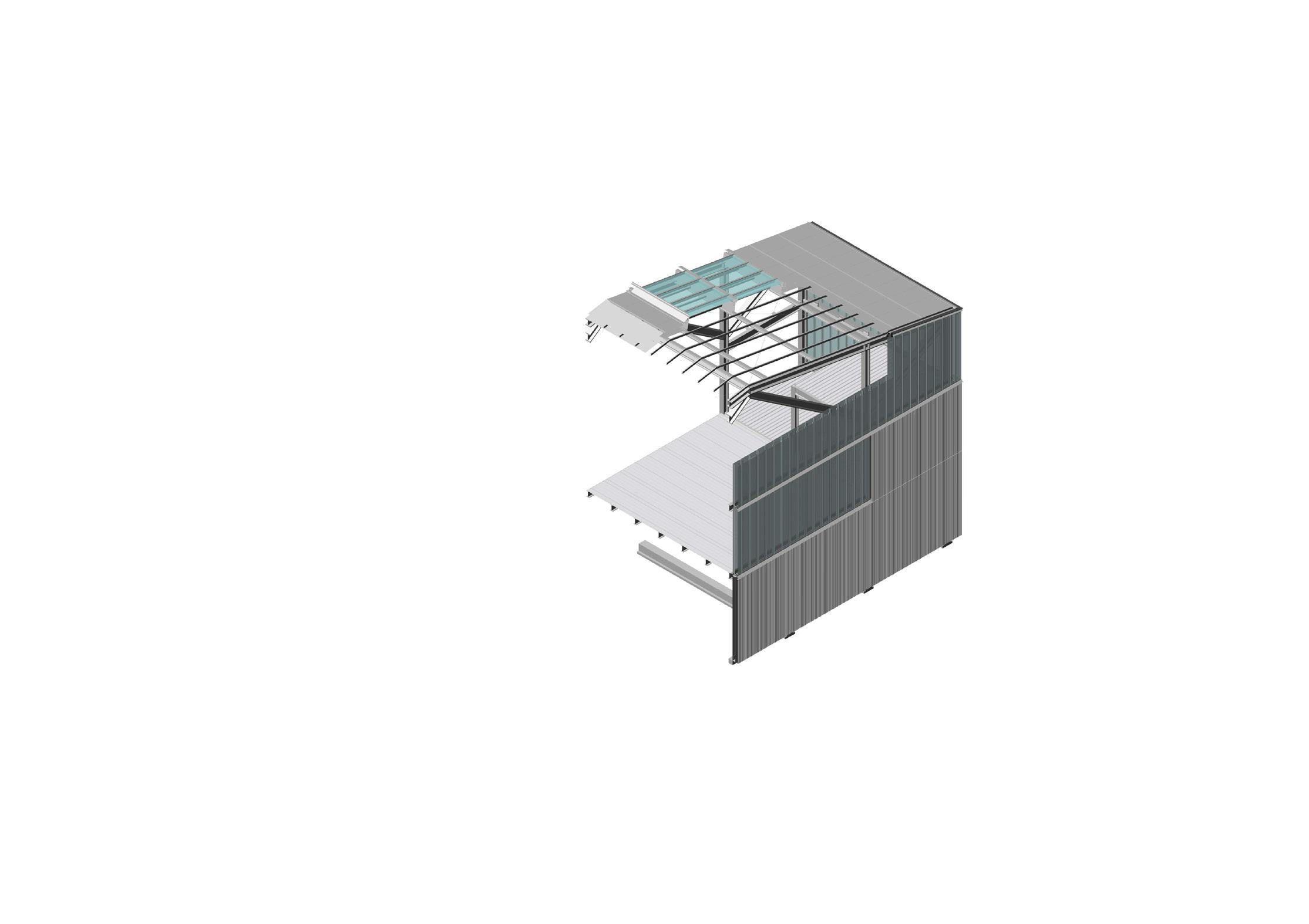
Giacomo Boffi Gian Luca Brunetti Marco Scaioni Politecnico di Milano School of Architecture, Urban Planning and Construction Engineering Course of Studies in Construction Architecture 2020-2021 Architecture Construction Studio teachers collaborators panel: GENERAL SECTION AND ELEVATION STRIP 1:50 date: scale: 5student Greta Cornaggia Iva Miteva 966705 05/02/2021 Imane El Bakkali 961849 Marianne Esses 967775 Eden Nimni 967144 Paolo Carlesso Manuel Garramone Eliana Tonelli OVERALL SECTION 1:50 ELEVATION STRIP 1:50 Giacomo Boffi Gian Luca Brunetti Marco Scaioni Politecnico di Milano School of Architecture, Urban Planning and Construction Engineering Course of Studies in Construction Architecture 2020-2021 Architecture Construction Studio AXONOMETRY - CONSTRUCTION PROCESS 6Greta Cornaggia Iva Miteva 966705 05/02/2021 Imane El Bakkali 961849 Marianne Esses 967775 Eden Nimni 967144 Paolo Carlesso Manuel Garramone Eliana Tonelli
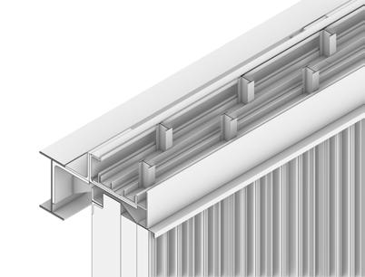
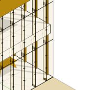
STRUCTURAL SKELETON
BUILDING FRAMES
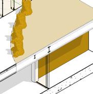
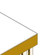
FINISHING LAYERS
TECHNICAL DETAILS
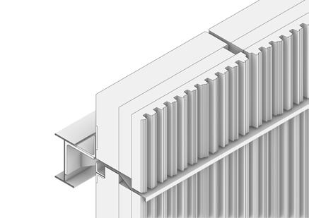
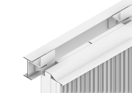
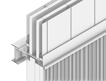
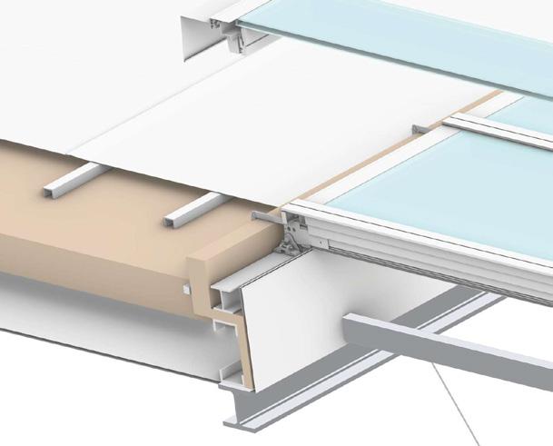
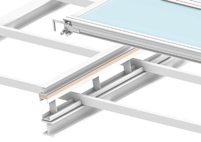
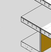
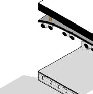
Giacomo Boffi Marco Scaioni Politecnico di Milano School of Architecture, Urban Planning and Construction Engineering 2020-2021 Architecture Construction Studio BUILDING ENVELOPE DETAILS - 1 1:5 7Greta Cornaggia Iva Miteva 966705 05/02/2021 Imane El Bakkali 961849 Marianne Esses 967775 Eden Nimni 967144 Paolo Carlesso Manuel Garramone Eliana Tonelli FACADE SECTION 1:20 PRECAST SANDWICH WALL CONNECTION TO CHANNEL GLASS WALL 1:5 SPRECACT SANDWICH WALL CONNECTION 1:5 3D CONSTRUCTION LAYERS channel glass wall : 1.u channel glass (30 mm) 2.Insulation Glass Channel TIMax™ W (60 mm) 3.air gap (80 mm) 4. bolted structural angles 5. u glass channels frames 6.sealant joint (14 mm) 7. aluminum profile (50 mm) concrete sandwich wall : 1.precast concrete (90 mm) 2.insulation (100 mm) 3.cladding (180 mm) 4.bolted structural angles 5. sealant joint (14 mm) 5 7 4 1 2 3 6 4 1 2 3 5 Gian Luca Brunetti Marco Scaioni Politecnico di Milano School of Architecture, Urban Planning and Construction Engineering Course of Studies in Construction Architecture 2020-2021 Architecture Construction Studio teachers collaborators panel: BUILDING ENVELOPE DETAILS - 2 1:10 date: 8student Greta Cornaggia Iva Miteva 966705 05/02/2021 Marianne Esses 967775 Eden Nimni 967144 Paolo Carlesso Manuel Garramone Eliana Tonelli scale: gypsum board (10mm) welded steel plates rockwool insulation (160mm) bolted structural angles rigid insulation (30mm) waterproof membrane flashing continuous channel steel cladding sheets floor finish in vinyl tiles radiant floor heating system - Valsir V-Esse acoustic insulation waterproof thermal insulation (100mm) vapor barrier concrete screed (40mm) ventilated plastic igloo floor system embedded soil tubes (d=300mm) concrete screed asphalt paving concrete curb metal grill filter fabric perforated drainage pipe in gravel bedding concrete screed (100mm) steel framing gutter
Giacomo Boffi Gian Luca Brunetti Marco Scaioni Politecnico di Milano School of Architecture, Urban Planning and Construction Engineering Course of Studies in Construction Architecture 2020-2021 Architecture Construction Studio teachers collaborators panel: BUILDING ENVELOPE DETAILS - 3 1:10 date: 9student Greta Cornaggia Iva Miteva 966705 05/02/2021 Imane El Bakkali 961849 Marianne Esses 967775 Eden Nimni 967144 Paolo Carlesso Manuel Garramone Eliana Tonelli scale: drip fabric roller blinds aluminium window frame fiber cement board fiber cement board flashing sealant joint rigid insulation board fiber cement board flashing rigid insulation board rigid insulation board fabric roller blinds aluminium window frame fiber cement board rigid insulation board Elevation Elevation Window Detail - Precast Concrete Sandwich Panel 1:10 Window Detail - Channel Glass Wall 1:10 Giacomo Boffi Gian Luca Brunetti Marco Scaioni Politecnico di Milano School of Architecture, Urban Planning and Construction Engineering Course of Studies in Construction Architecture 2020-2021 Architecture Construction Studio panel: BUILDING ENVELOPE DETAILS - 4 1:20 10Greta Cornaggia Iva Miteva 966705 05/02/2021 Imane El Bakkali 961849 Marianne Esses 967775 Eden Nimni 967144 Paolo Carlesso Manuel Garramone Eliana Tonelli STEP 1 Roof Framing GENERAL ROOF SECTION 1:20 STEP 2 Roof Layers
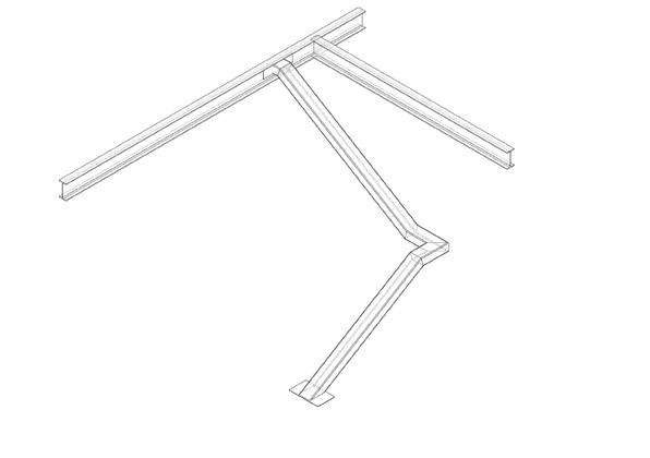
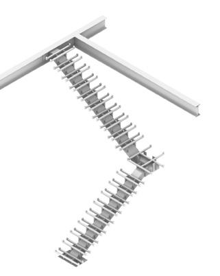
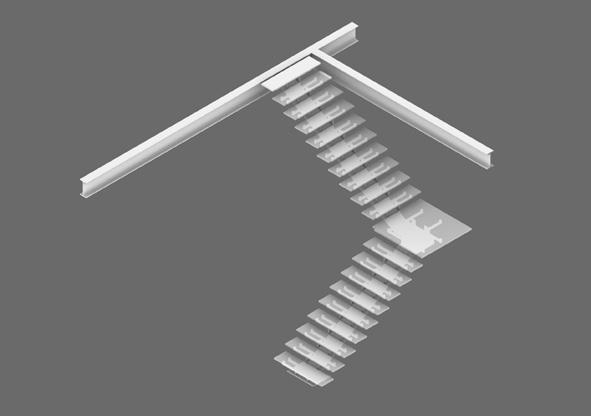
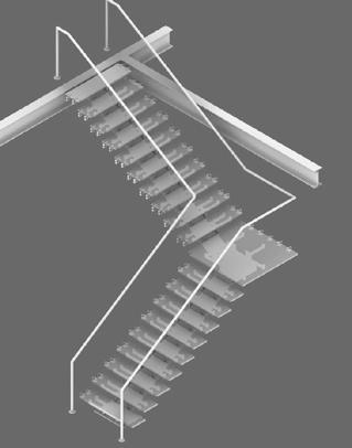
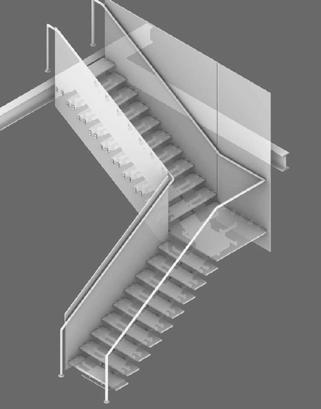
1 1 2 3 4 2 3 4 Gian Luca Brunetti Marco Scaioni Politecnico di Milano School of Architecture, Urban Planning and Construction Engineering Course of Studies in Construction Architecture 2020-2021 Architecture Construction Studio teachers collaborators panel: INTERNAL PARTITIONS DETAILS 1:5 date: 12student Greta Cornaggia Iva Miteva 966705 05/02/2021 Imane El Bakkali 961849 Marianne Esses 967775 Eden Nimni 967144 Paolo Carlesso Manuel Garramone Eliana Tonelli scale: 1:50 scale: Giacomo Boffi Gian Luca Brunetti Marco Scaioni Politecnico di Milano School of Architecture, Urban Planning and Construction Engineering Course of Studies in Construction Architecture 2020-2021 Architecture Construction Studio panel: INTERNAL PARTITIONS - GLASS STAIRCASE 1:20 13Greta Cornaggia Iva Miteva 966705 05/02/2021 Imane El Bakkali 961849 Marianne Esses 967775 Eden Nimni 967144 Paolo Carlesso Manuel Garramone Eliana Tonelli GLASS STAIRCASE PLAN 1:20 GLASS STAIRCASE SECTION 1:20 CONSTRUCTION PROCESS 1 2 3 4 5
PV Panels 1 x 2.5 m
PV Panels 1 x 2.5 m
Exhaust duct for heat pump
Exhaust duct for heat pump
Ground air heat exchanger system intake
Ground air heat exchanger system intake
Heat Exchanger
Heat Exchanger
Air-sourced VRV heat pump
Air-sourced VRV heat pump
Suction duct for heat pump
Suction duct for heat pump
Manifolds for underfloor heating
Manifolds for underfloor heating
Embedded soil tubes 30 cm diameter
Embedded soil tubes 30 cm diameter
Ground air heat exchanger system intake
Ground air heat exchanger system intake
Manifolds for underfloor heating Suction duct for heat pump
Manifolds for underfloor heating Suction duct for heat pump
Exhaust duct for heat pump
Exhaust duct for heat pump
Solar inverter
Solar inverter
Construction Studio teachers collaborators panel:date:student
teachers collaborators panel:date:student
15 scale: 15 scale:
Giacomo Boffi Gian Luca Brunetti Marco Scaioni Politecnico di Milano School of Architecture, Urban Planning and Construction Engineering Course of Studies in Construction Architecture 2020-2021 Architecture Construction Studio teachers collaborators panel:date:student Greta Cornaggia Iva Miteva 966705 05/02/2021 Imane El Bakkali 961849 Marianne Esses 967775 Eden Nimni 967144 Paolo Carlesso Manuel Garramone Eliana Tonelli U VALUE- ROOF U VALUE- WALLS ROOF PLAN 1:100 180 sq.m 180 sq.m 180 sq.m 180 sq.m 1/1001/100 1.67 1.672.06 1.67 2.06 2.06 1.40 0.46 1.40 2.06 2.06 2.06 14.09 14.09 14.09 14.09 1.671.671.67 layers- roof THIKNESS M thermal conductivity mk/W thikness/thermal conductivity steel sheet 0.026 26 0.001 air gap 0.04 0.0262 1.526717557 rigid insulation 0.16 0.038 4.210526316 steal purlins 0.1 26 0.003846154 gypsum baord 0.013 0.25 0.052 sum 5.794090027 fixed value 0.16 fixed value 0.17 sum of values 6.124090027 FINAL U VALUE (1/sum of values) 0.163289566 W/mk layers- channel glass wall u channel glass 30 mm Insulation Glass Channel TIMax™ mm air gap 80 mm Insulation Glass Channel TIMax™ mm u channel glass 30 mm
WALLS
DRAINAGE SYSTEM PLAN DETAILS 1:10 precast concrete sandwich panels
DRAINAGE SYSTEM PLAN DETAILS 1:10
precast concrete sandwich panels
two-stage sealant joint (20mm)
EPS rigid insulation (100mm)
two-stage sealant joint (20mm)
EPS rigid insulation (100mm)
reinforced precast concrete wythe (180mm) formwork precast concrete wythe (50+50mm)
reinforced precast concrete wythe (180mm) formwork precast concrete wythe (50+50mm)
channel glass walls
channel glass walls
steel I-stud frame (500mm spacing)
steel I-stud frame (500mm spacing)
Wacotech™ TIMax Channel Glass Insulation (60mm) sealant joint (12mm) channel glass profile (498x48mm)
Wacotech™ TIMax Channel Glass Insulation (60mm) sealant joint (12mm) channel glass profile (498x48mm)
vapor barrier
vapor barrier
U VALUE- WALLS
foam insulation vapor barrier
foam insulation
fiber cement cladding
fiber cement cladding
structural channel cast steel bracket
downpipe bracket
structural channel cast steel bracket rainwater downpipe
structural angle
vapor barrier
rainwater downpipe downpipe bracket
structural angle
BUILDING ENVELOPE DETAILS - 5 11
wall THIKNESS M thermal conductivity mk/W thikness/thermal conductivity 0.03 0.96 0.03125 TIMax™ W 60 0.06 0,1 0.6 0.08 0.0262 3.053435115 TIMax™ W 60 0.06 0,1 0.6 0.03 0.96 0.03125 sum 4.315935115 fixed value 0.16 fixed value 0.17 sum of values 4.645935115 FINAL U VALUE (1/sum of values) 0.215241921 W/mk layers- sandwich wall THIKNESS M thermal conductivity mk/W thikness/thermal conductivity precast concrete 0.09 0.38 0.236842105 insulation 0.1 0.038 2.631578947 cladding 0.18 0.38 0.473684211 sum 3.342105263 fixed value 0.16 fixed value 0.17 sum of values 3.672105263 FINAL U VALUE (1/sum of values) 0.272323348 W/mk panel: BUILDING ENVELOPE DETAILS - 5 date: 1105/02/2021
1/100 14.09 14.09 layers- channel glass wall THIKNESS M thermal conductivity mk/W thikness/thermal conductivity u channel glass 30 mm 0.03 0.96 0.03125 Insulation Glass Channel TIMax™ W 60 mm 0.06 0,1 0.6 air gap 80 mm 0.08 0.0262 3.053435115 Insulation Glass Channel TIMax™ W 60 mm 0.06 0,1 0.6 u channel glass 30 mm 0.03 0.96 0.03125 sum 4.315935115 fixed value 0.16 fixed value 0.17 sum of values 4.645935115 FINAL U VALUE (1/sum of values) 0.215241921 W/mk layers- sandwich wall THIKNESS M thermal conductivity mk/W thikness/thermal conductivity precast concrete 0.09 0.38 0.236842105 insulation 0.1 0.038 2.631578947 cladding 0.18 0.38 0.473684211 sum 3.342105263 fixed value 0.16 fixed value 0.17 sum of values 3.672105263 FINAL U VALUE (1/sum of values) 0.272323348 W/mk
skyscraper
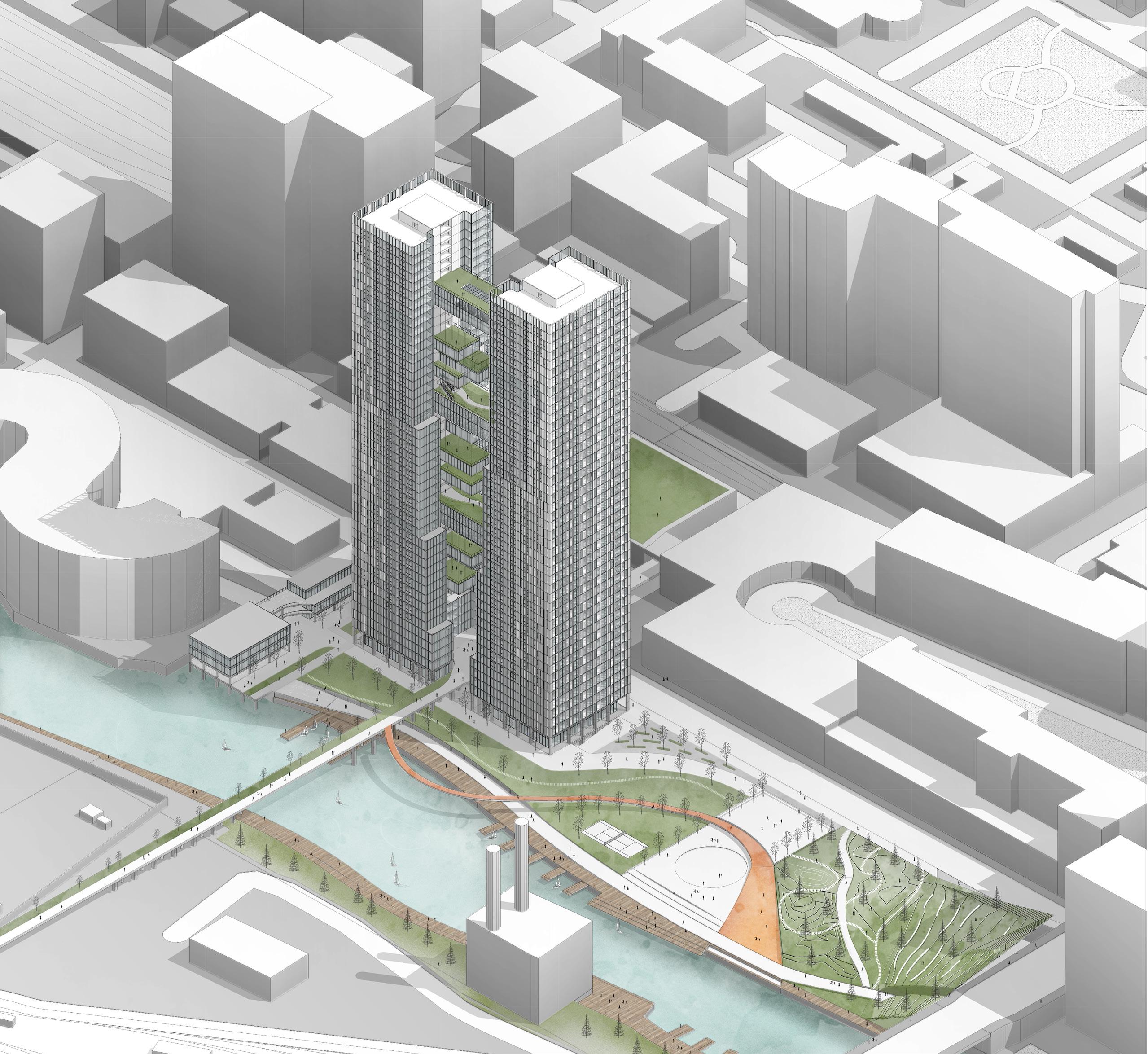
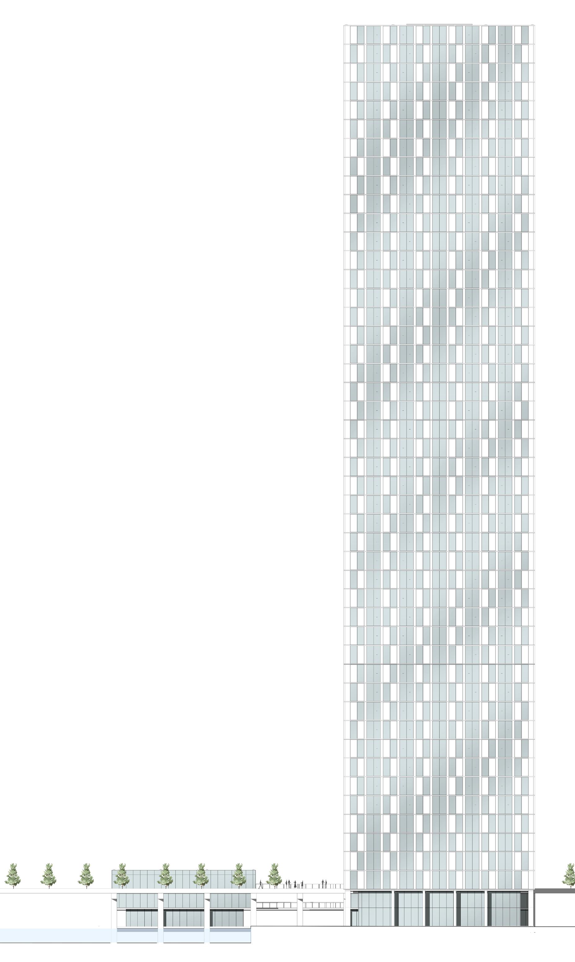
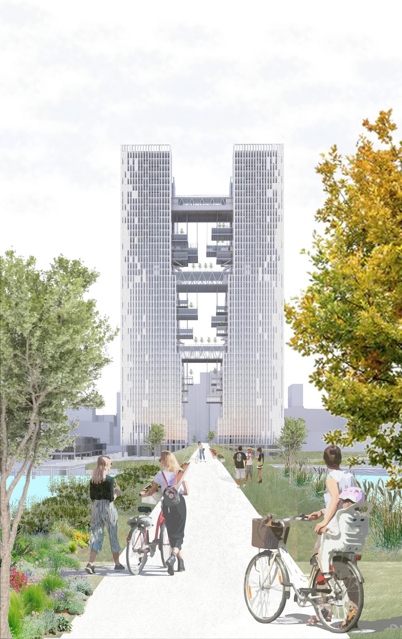
THE SPLIT, CHICAGO IL| Residential
Building Functions

Planning and Program Parameters
3 residential floor types:
Type A: level 7-16 (10 floors)
6 apartments per tower, 12 apartments per floor 4x 3 bedroom apt., 4x2 bedroom apt., 4x 1 bedroom apt. (4*10*4)+(4*10*3)+(4*10*2) = 160 + 120 + 80 = 360 residents
Type B: level 19-28 (10 floors)
6 apartments per tower, 12 apartments per floor 4x 3 bedroom apt., 8x 1 bedroom apt. (4*10*4)+(8*10*2) = 160 + 160 = 320 residents
Type C: level 31-48 (16 floors)
4 apartments per tower, 8 apartments per floor 4x 3 bedroom apt., 4x 2 bedroom apt. (4*16*4)+(4*16*3) = 256 + 192 = 488 residents
Total approximate number of residents: 1,128 residents
Dwelling unit sizes:
bedroom apt.: +/- 60-65
bedroom apt.:
20-50
90-100
1
sqm +
sqm loggia 2
+/-
sqm + 60-65 sqm loggia 3 bedroom apt.: +/- 180 sqm + 95 sqm loggia
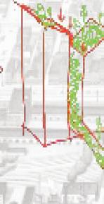
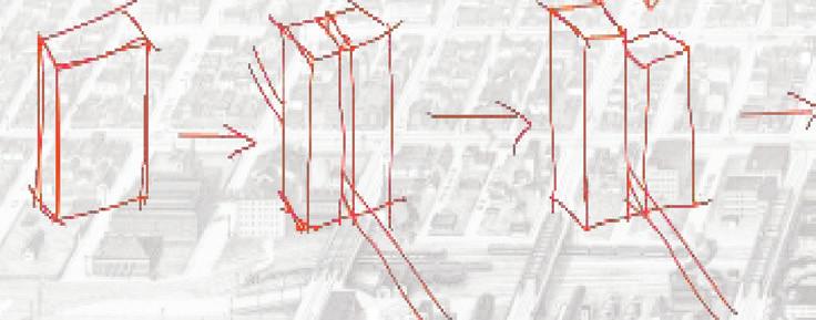
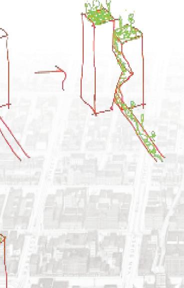
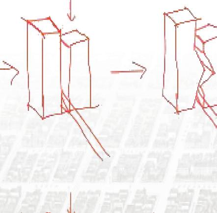
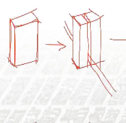
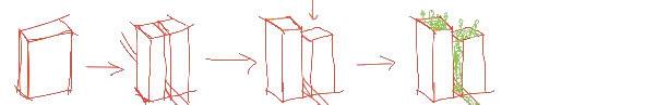
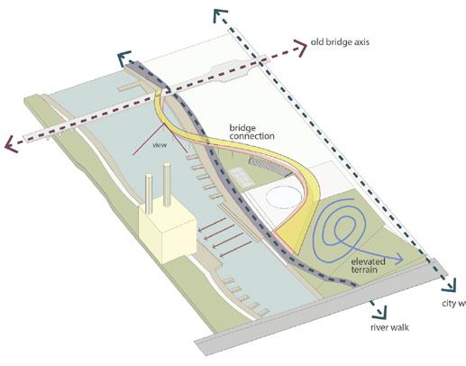
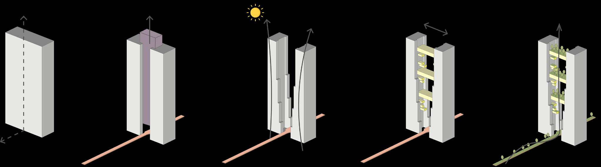
The
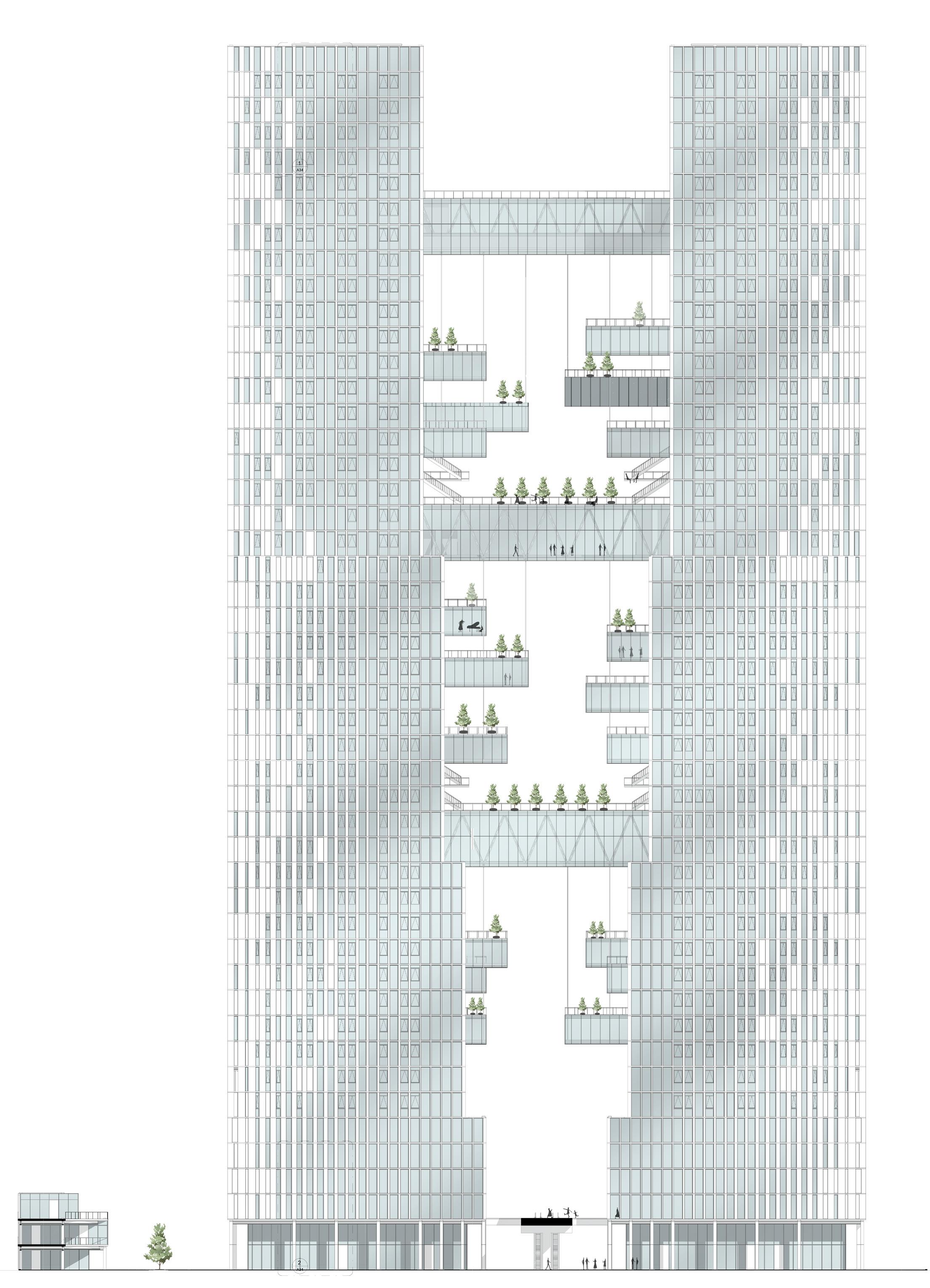
old bridge is replicated and cuts the volume to form two towers. The building is located on the main axis that continues along the historical grid. The space between the two towers is increased by cropping the edge of the volumes to receive more light.
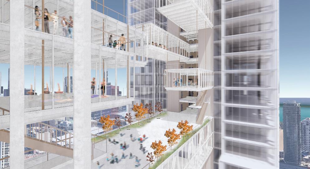
Bridges
between the towers are added to host different amenities. Vegetation is added along the city bridge and the roof of the central sky bridges to emphasize the split and
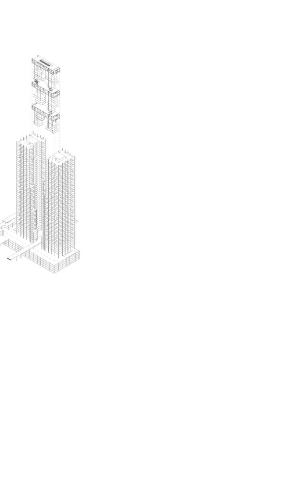
Building Strategy Landscape Strategy Access & Circulation Functions & Amenities Exploded Axo Section A through Bridges A
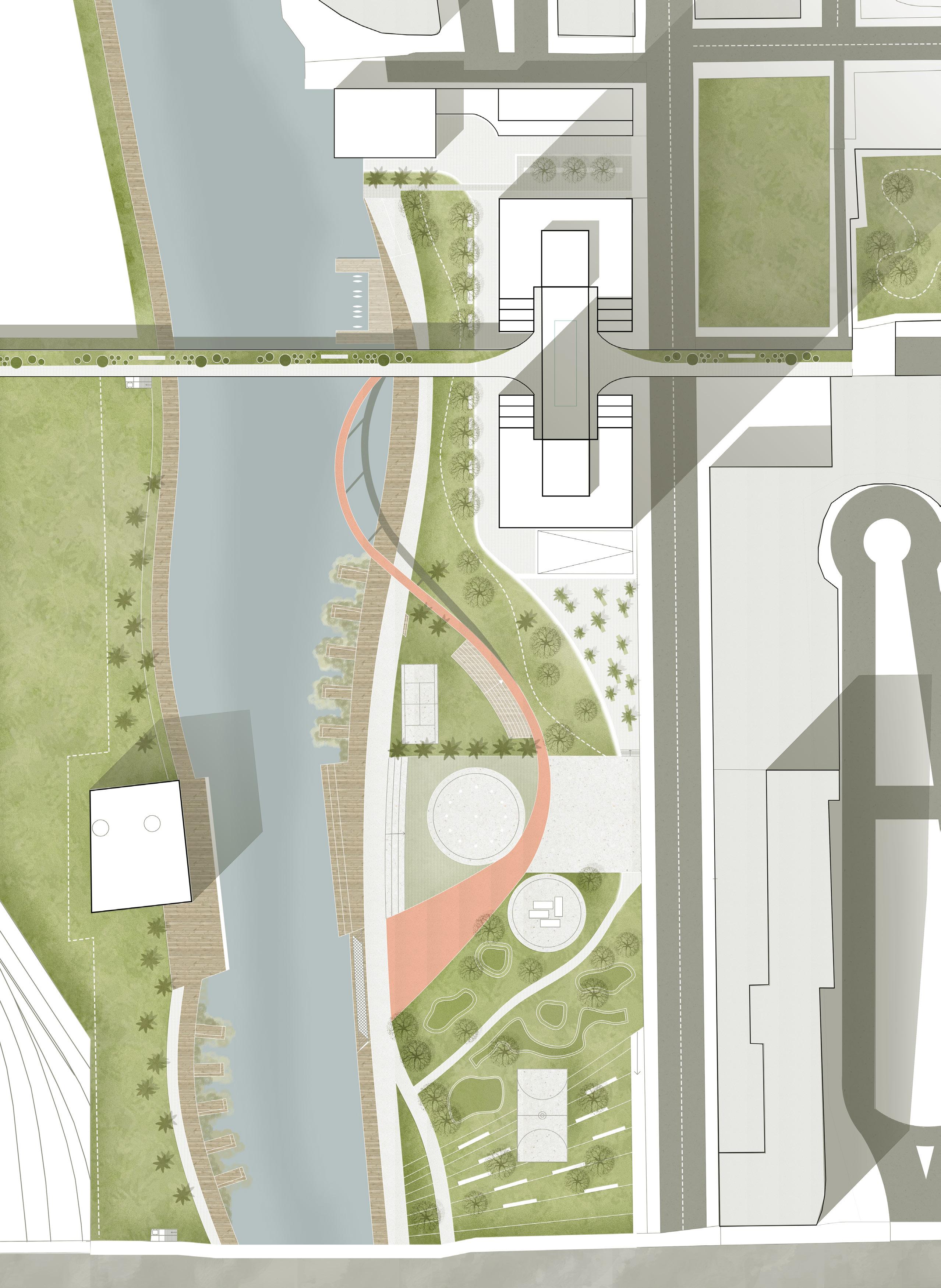
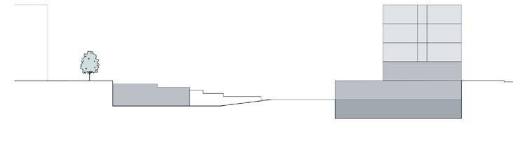
Site Plan Scale: 1:500 concert stage water square wetland pedestrian bridge kayak parking tennis court basketball court green hill river walk deck walk city walk outdoor exhibition +8.00 -2.00 -2.20 +0.00 -1.50 -1.50 +0.60 +0.00 +12.00 -2.20
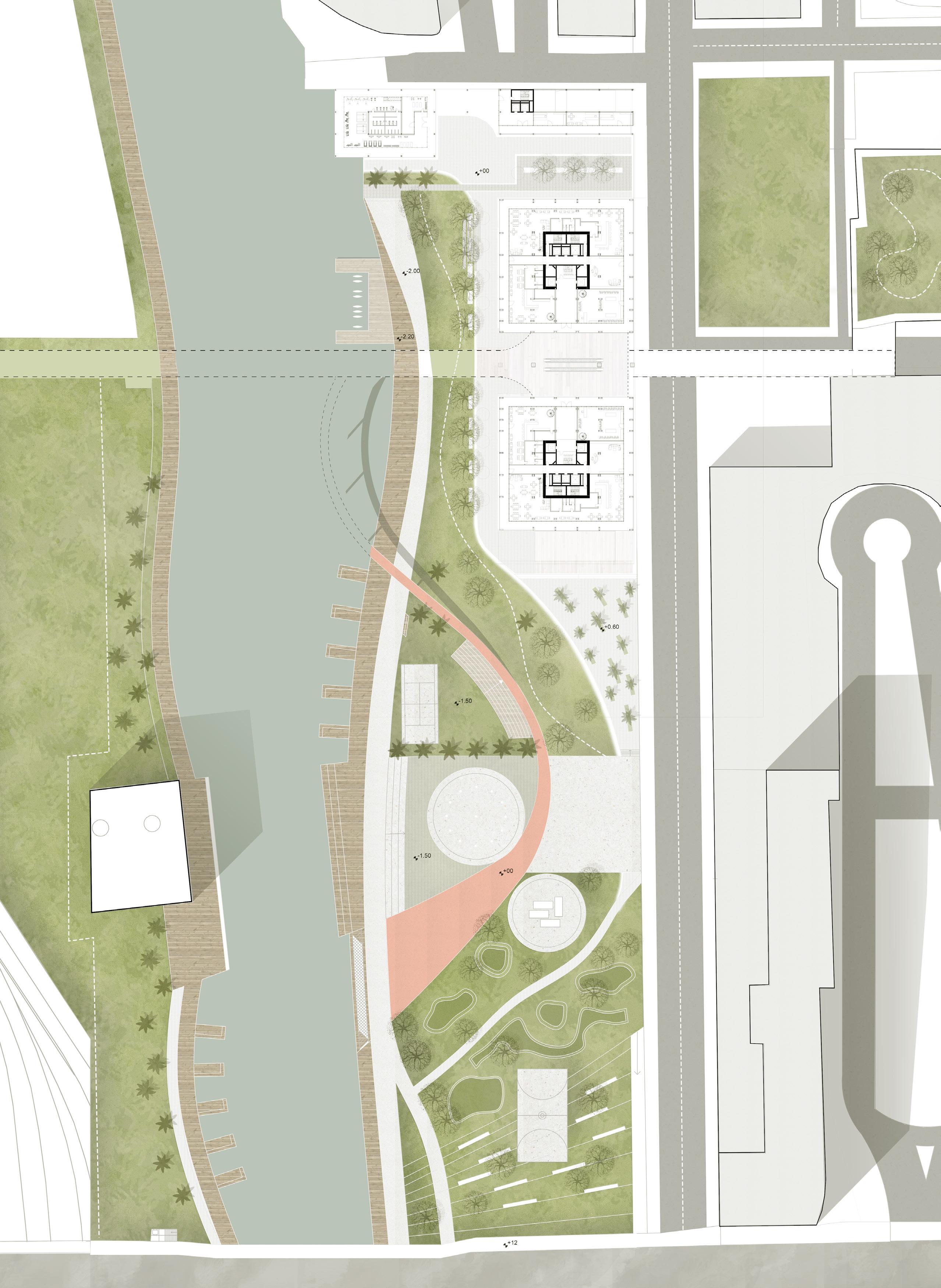
Ground Floor Plan Scale: 1:500 concert stage water square wetland pedestrian bridge kayak parking tennis court basketball court green hill river walk deck walk city walk outdoor exhibition +8.00 -2.00 -2.20 +0.00 +0.00 +12.00 -2.20
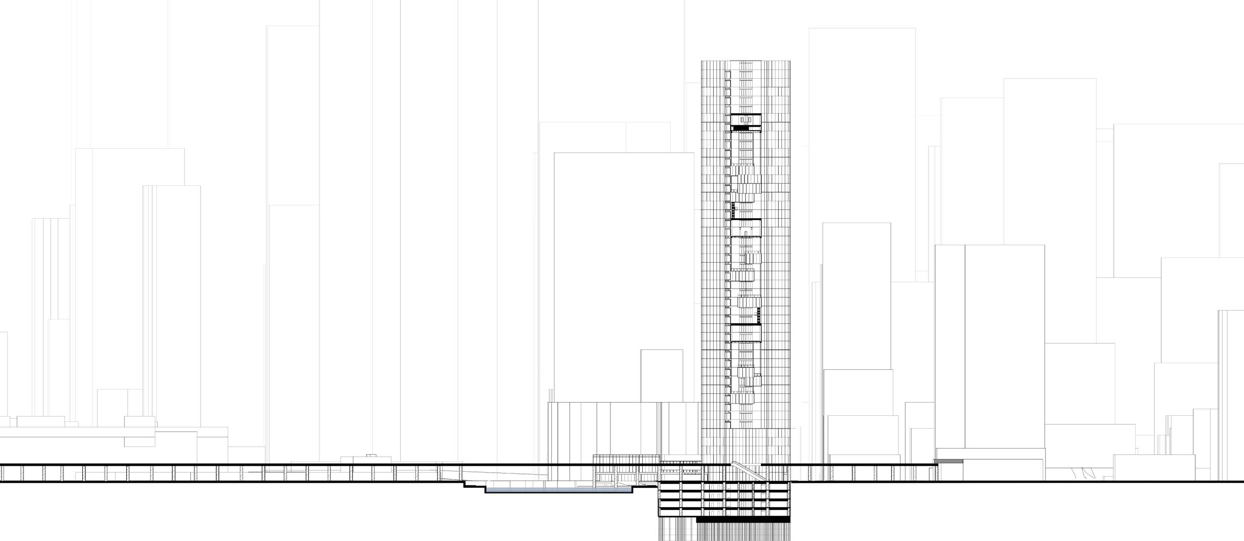
Site Section Scale: 1:1000 Street Elevation Scale: 1:1000
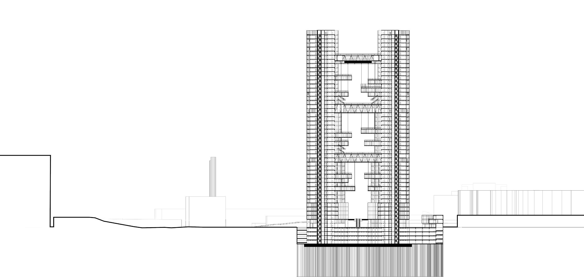
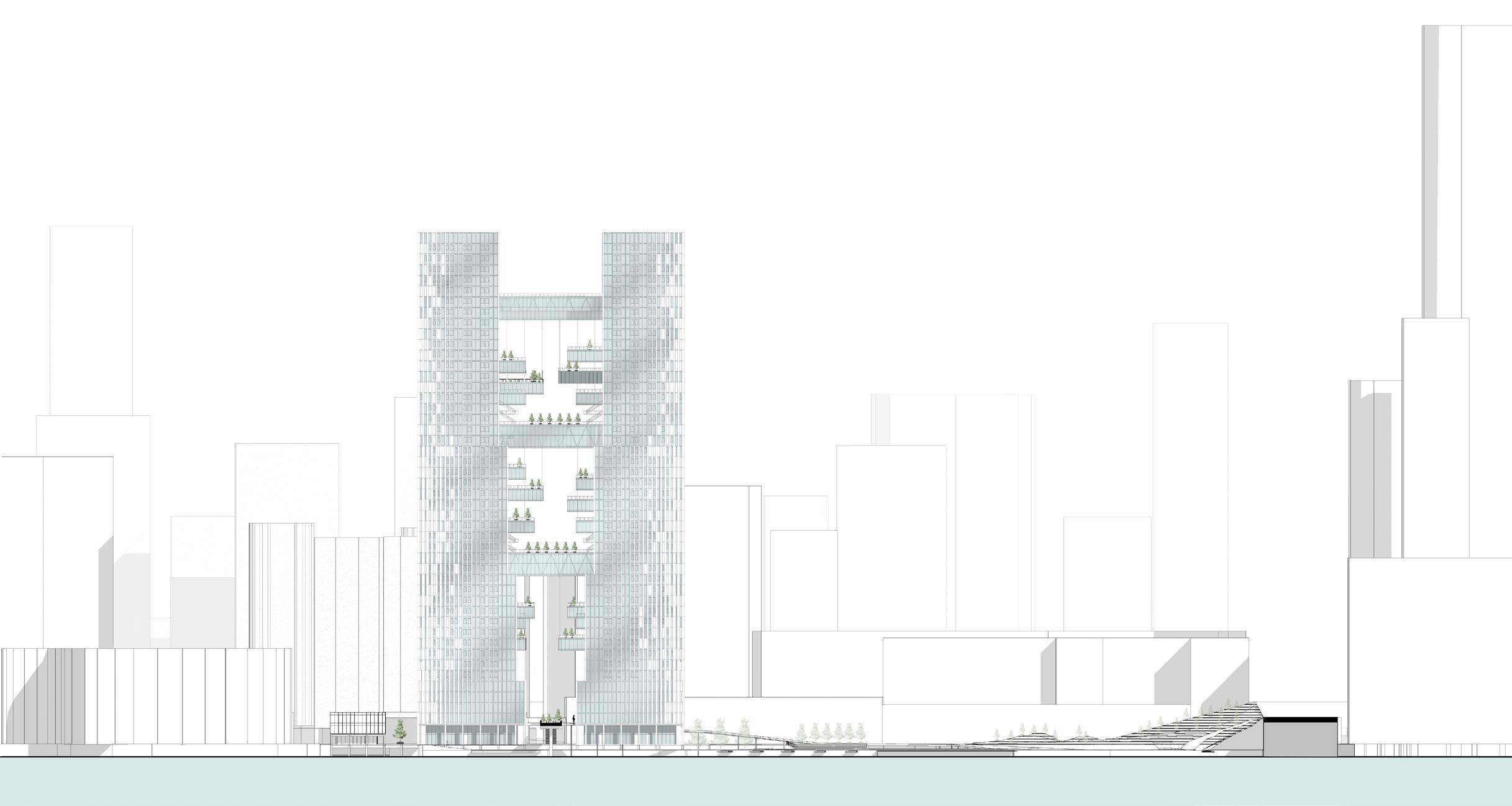
Site Section Scale: 1:1000 Street Elevation Scale: 1:1000
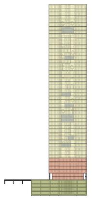
POLITECNICO DI MILANO SCHOOL OF ARCHITECTURE URBAN PLANNING AND CONSTRUCTION ENGINEERING Architectural Design Studio for Complex Constructions 1-B AY 2020-21 Prof. A. Azzolini, Prof. M. Sabini, PROJECT The Split GROUP Jordan Cong Dat Dihn 964222 Beren Denizkurt 965419 West Elevation Scale: 1:200
POLITECNICO DI MILANO SCHOOL OF ARCHITECTURE URBAN PLANNING Architectural Design Studio for Complex Constructions 1-B AY 2020-21 PROJECT GROUP Jordan Cong Dat Dihn 964222 South Elevation
View from the Bridge Across the River
Scale: 1:200
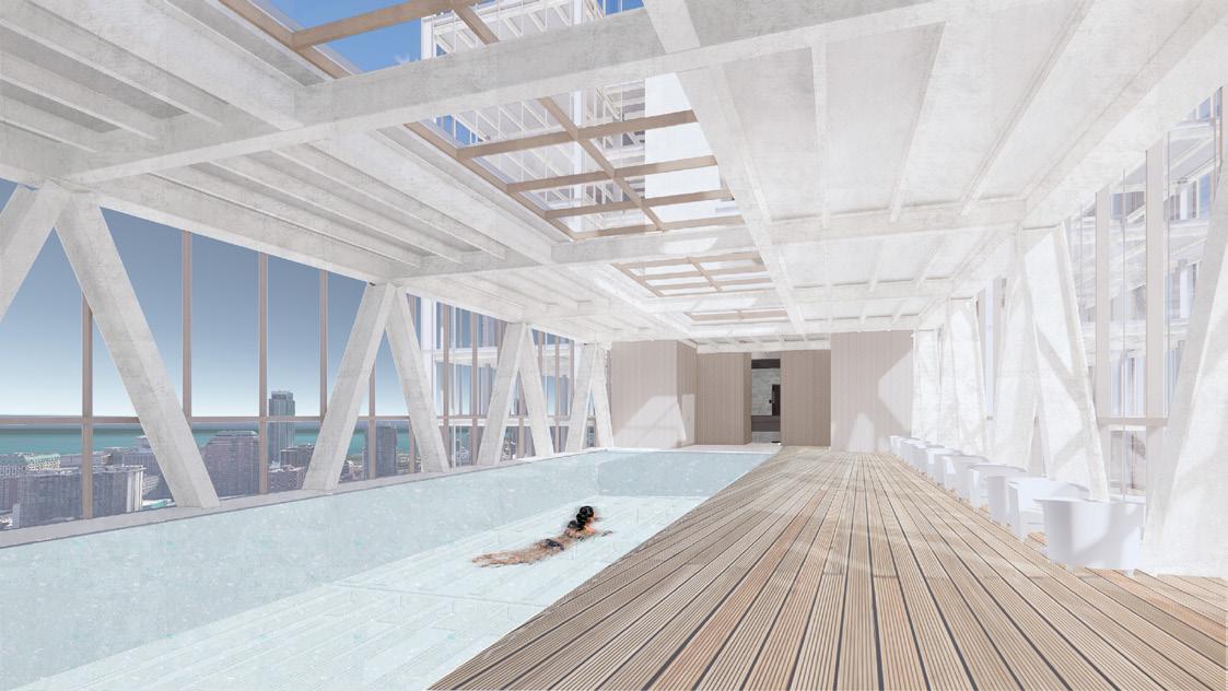
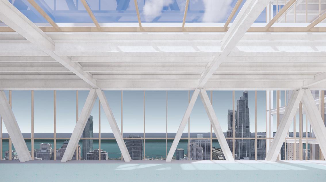
POLITECNICO MILANO SCHOOL OF ARCHITECTURE URBAN PLANNING AND CONSTRUCTION ENGINEERING BUILDING ARCHITECTURE (MI) Architectural Design Studio for Complex Constructions 1-B AY 2020-21 Prof. A. Azzolini, Prof. M. Sabini, Prof. C. Mirarchi, Prof. R. Shehu PROJECT The Split Chicago, GROUP Jordan Cong Dat Dihn 964222 Beren Denizkurt 965419 Marianne Esses 967775 Eden Nimni 967144 DN 14 14 6 6 5 5 4 4 3 3 2 2 10 10 15 15 16 16 17 17 18 18 F F E E D D C C B B A A 23 23 22 22 21 21 20 20 19 19 E 1 E 1 D 1 D 1 C C B 1 B 1 A 1 A 1 12 12 8 8 7 7 9 9 13 13 11 11 UP Mezzanine Floor Plan Scale: 1:200 Architectural Design Studio for Complex Constructions 1-B 1414 66 55 44 33 22 1010 1515 1616 1717 1818 F F D D C C B B A A 1212 88 77 99 1313 1111 E E 9900 6600 6600 16500 39600 9900 6600 6600 6600 3300 3300 3300 9900 9900 3300 3300 3300 6600 6600 6600 9900 99000 Hanged Bridge Floor Plan - Level 35 Pool Skybridge - Level 42 Scale: 1:200 Scale: 1:200 1414 66 55 44 33 22 1010 1515 1616 1717 1818 F F D D C C B B A A 1212 88 77 99 1313 1111 E E 9900 6600 6600 6600 3300 3300 3300 9900 9900 3300 3300 3300 6600 6600 6600 9900 99000 14 6 5 4 3 2 10 15 16 17 18 F F D D C C B B A A 12 8 7 9 13 11 E E 9900 6600 6600 16500 39600 9900 6600 6600 6600 3300 3300 3300 9900 9900 3300 3300 3300 6600 6600 6600 9900 99000 Hanged Bridge Floor Plan - Level 35 Pool Skybridge - Level 42 Scale: 1:200 Scale: 1:200 1414 66 55 44 33 22 1010 1515 1616 1717 1818 F F D D C C B B A A 1212 88 77 99 1313 1111 E E 9900 6600 6600 6600 3300 3300 3300 9900 9900 3300 3300 3300 6600 6600 6600 9900 9900 6600 6600 16500 39600 99000
POLITECNICO DI MILANO SCHOOL OF ARCHITECTURE URBAN PLANNING AND CONSTRUCTION ENGINEERING BUILDING ARCHITECTURE (MI) Architectural Design Studio for Complex Constructions 1-B AY 2020-21 Prof. A. Azzolini, Prof. M. Sabini, Prof. C. Mirarchi, Prof. R. Shehu PROJECT The Split Chicago, IL GROUP Jordan Cong Dat Dihn 964222 Beren Denizkurt 965419 Marianne Esses 967775 Eden Nimni 967144 1414 66 55 44 33 22 1010 1515 1616 1717 1818 F F D D C C B B A A 2323 2222 2121 2020 1919 E1 E1 D1 D1 11 6600 6600 6600 6600 6600 9900 6600 19800 13200 13200 6600 6600 6600 6600 9900 9900 9900 9900 9900 6600 6600 16500 1212 88 77 99 1313 1111 F F E E Parking Area Floor Plan - Level -01 Scale: 1:200
POLITECNICO DI MILANO SCHOOL OF ARCHITECTURE URBAN PLANNING Architectural Design Studio for Complex Constructions 1-B AY 2020-21 PROJECT GROUP Jordan Cong Dat Dihn 964222 Beren Denizkurt 965419 14 6 5 4 3 2 10 15 16 17 18 F F D D C C B B A A 12 8 7 9 13 11 9900 6600 6600 16500 39600 E E 9900 6600 6600 6600 3300 3300 3300 9900 9900 3300 3300 3300 6600 6600 6600 9900 99000 Typical Floor Plan - Level 45 Scale: 1:200 Section 02 Scale: 1:200 02 Level_01 0.0000 Level_02 4.0000 Level_03 8.0000 Level_04 12.0000 Level_05 16.0000 Level_06 20.0000 Level_07 24.0000 Level_08 28.0000 Level_09 32.0000 Level_10 36.0000 Level_11 40.0000 Level_12 44.0000 Level_13 48.0000 Level_14 52.0000 Level_15 56.0000 Level_16 60.0000 Level_17 64.0000 Level_18 68.0000 Level_19 72.0000 Level_20 76.0000 Level_21 80.0000 Level_22 84.0000 Level_23 88.0000 Level_24 92.0000 Level_25 96.0000 Level_26 100.0000 Level_27 104.0000 Level_28 108.0000 Level_29 112.0000 Level_30 116.0000 Level_31 120.0000 Level_32 124.0000 Level_33 128.0000 Level_34 132.0000 Level_35 136.0000 Level_36 140.0000 Level_37 144.0000 Level_38 148.0000 Level_ 01 4.0000 Level_ 02 8.0000 ABCDF Level_ 03 12.0000 Level_ 04 16.0000 DE1 1 Level_39 152.0000 Level_41 160.0000 Level_42 164.0000 Level_43 168.0000 Level_44 172.0000 Level_45 176.0000 Level_46 180.0000 Level_47 184.0000 Level_48 188.0000 Level_49 192.0000 Level_40 156.0000 DETAIL 09 E
POLITECNICO DI MILANO SCHOOL OF ARCHITECTURE URBAN PLANNING AND CONSTRUCTION ENGINEERING Architectural Design Studio for Complex Constructions 1-B AY 2020-21 Prof. A. Azzolini, Prof. M. Sabini, PROJECT The Split GROUP Jordan Cong Dat Dihn 964222 Beren Denizkurt 965419 Marianne Esses 967775 1-Bedroom Apartment Section 1-Bedroom Apartment Plan Scale: 1:50 Scale: 1:50
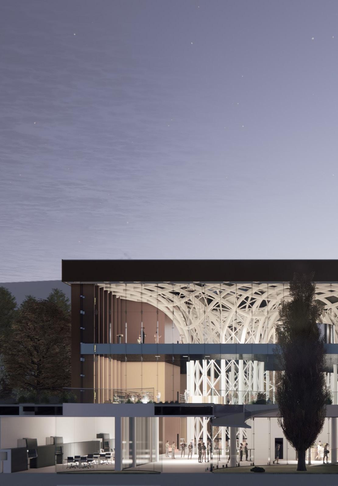
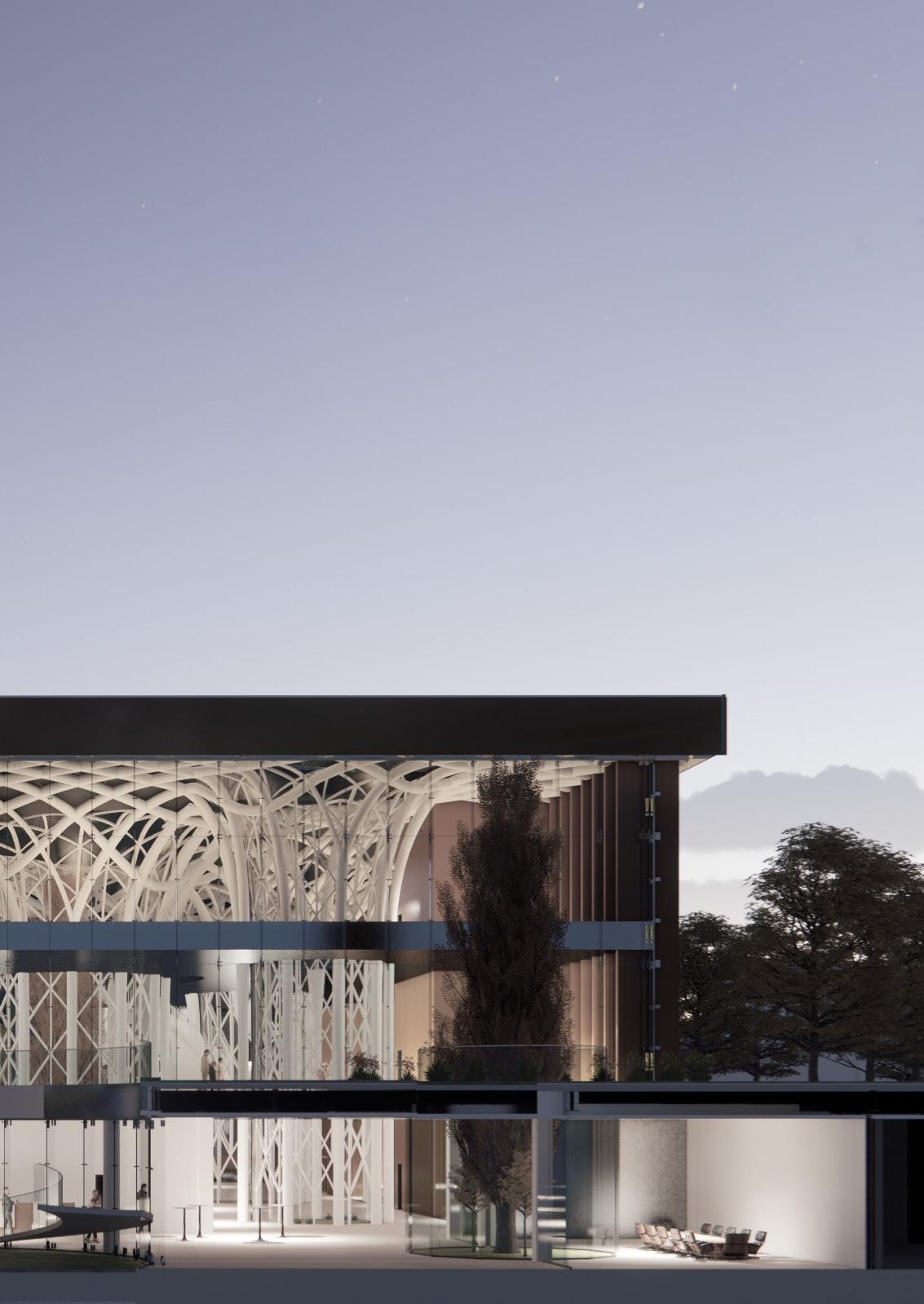
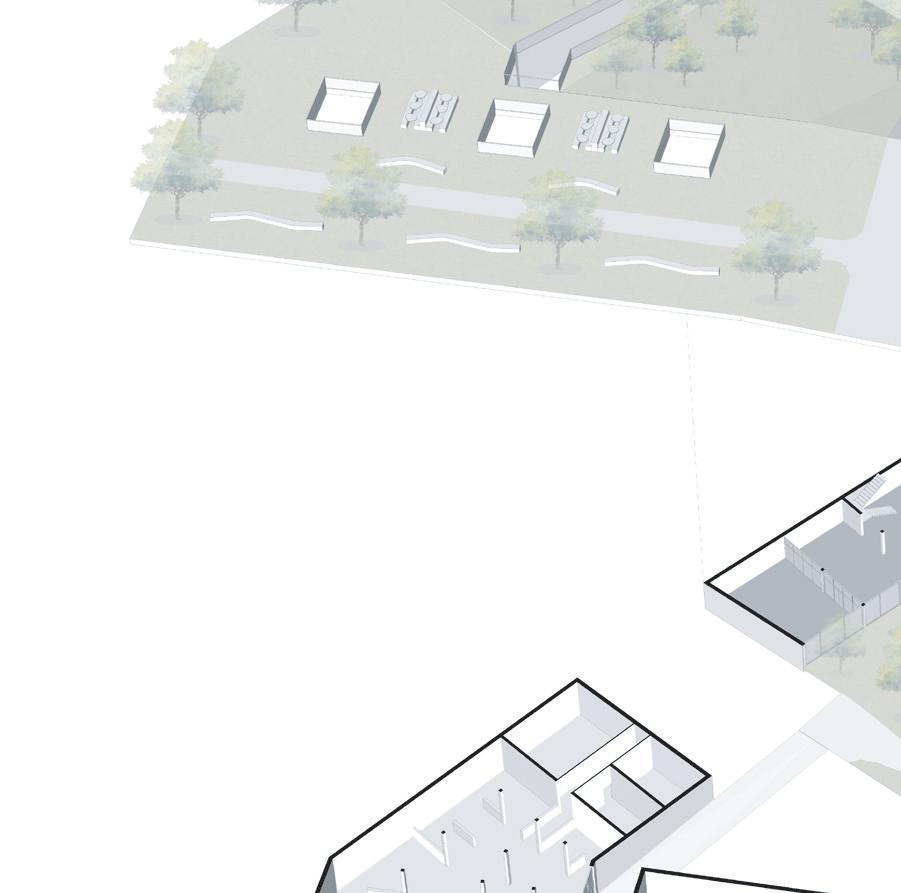
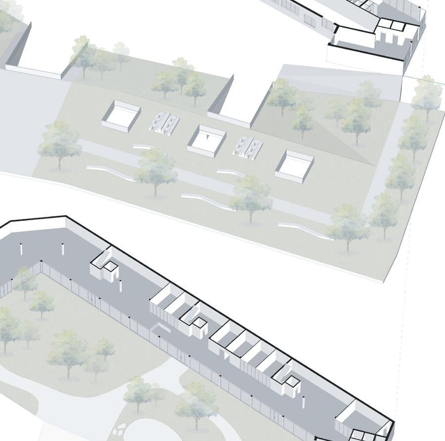
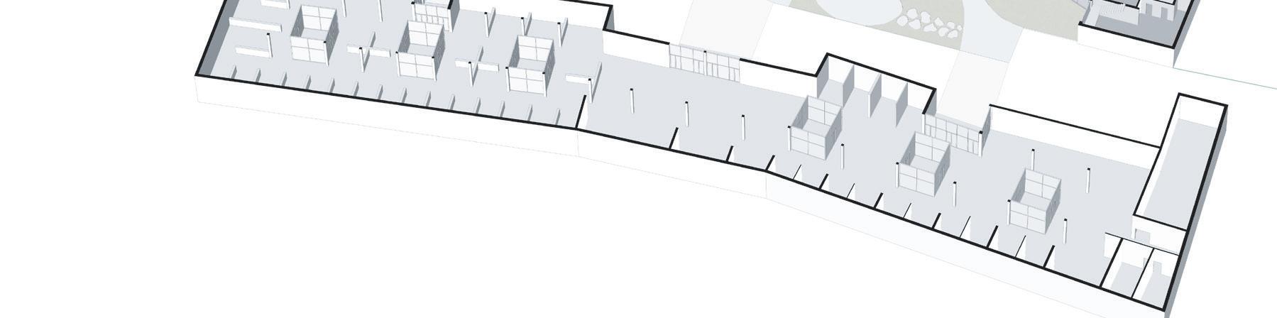
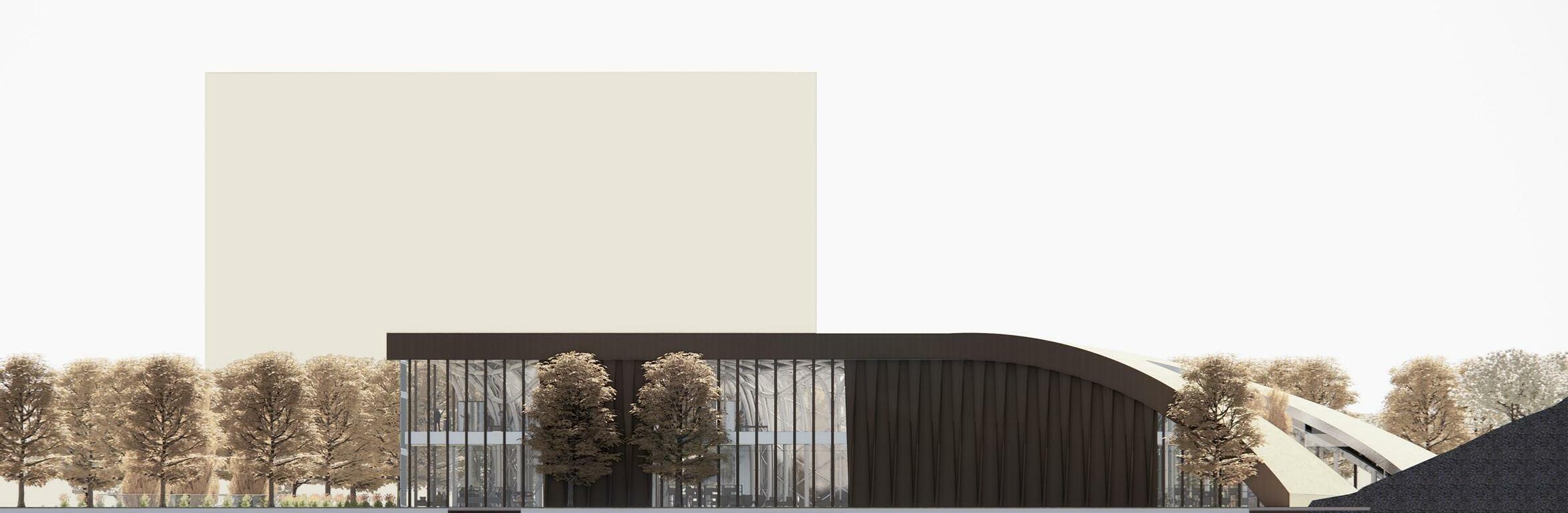
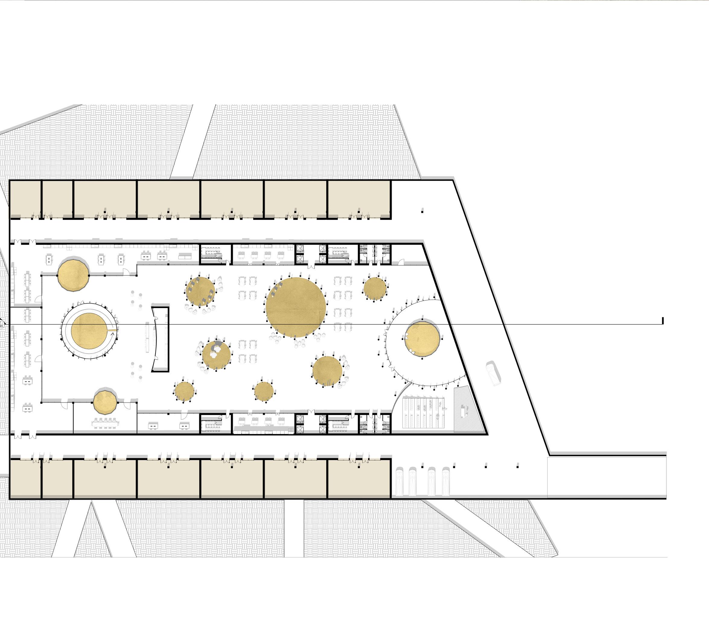
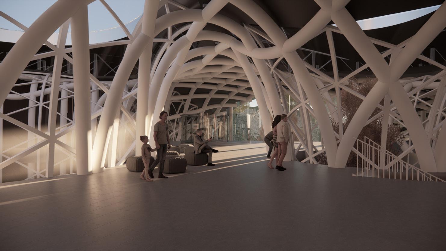
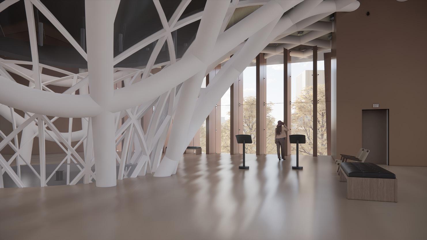
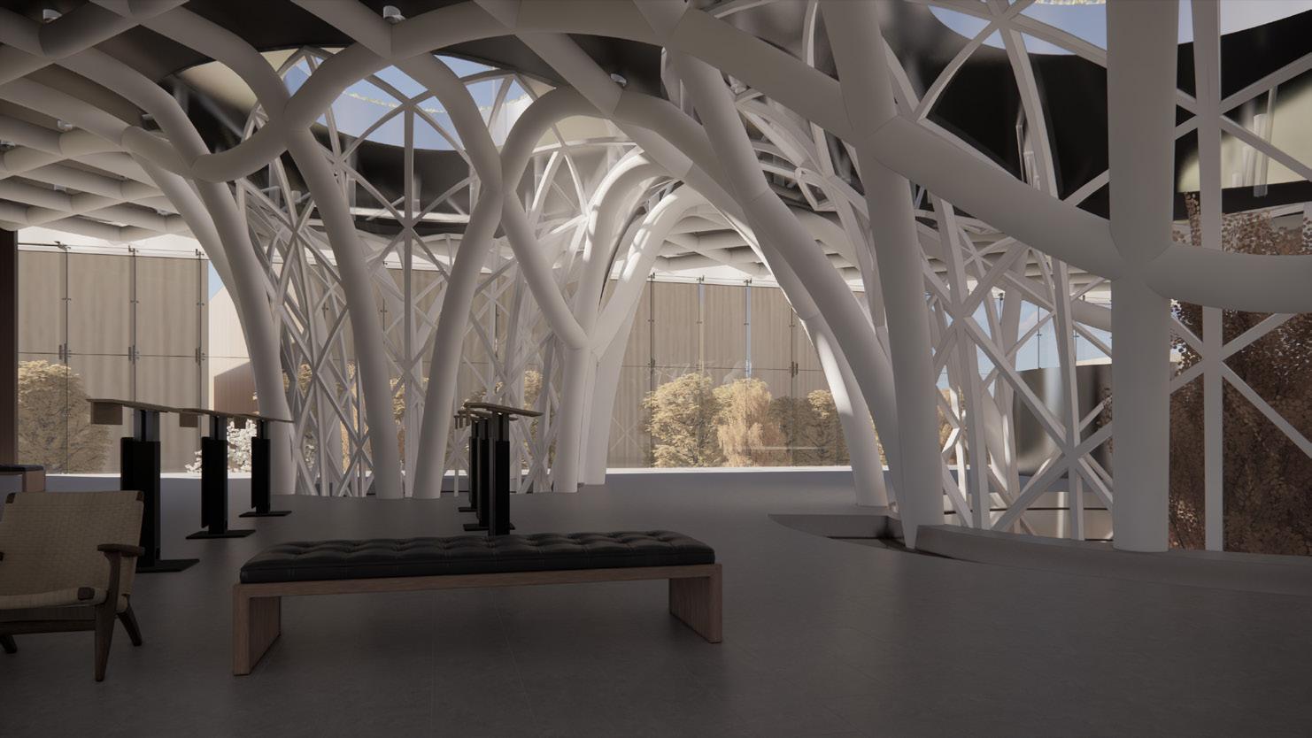
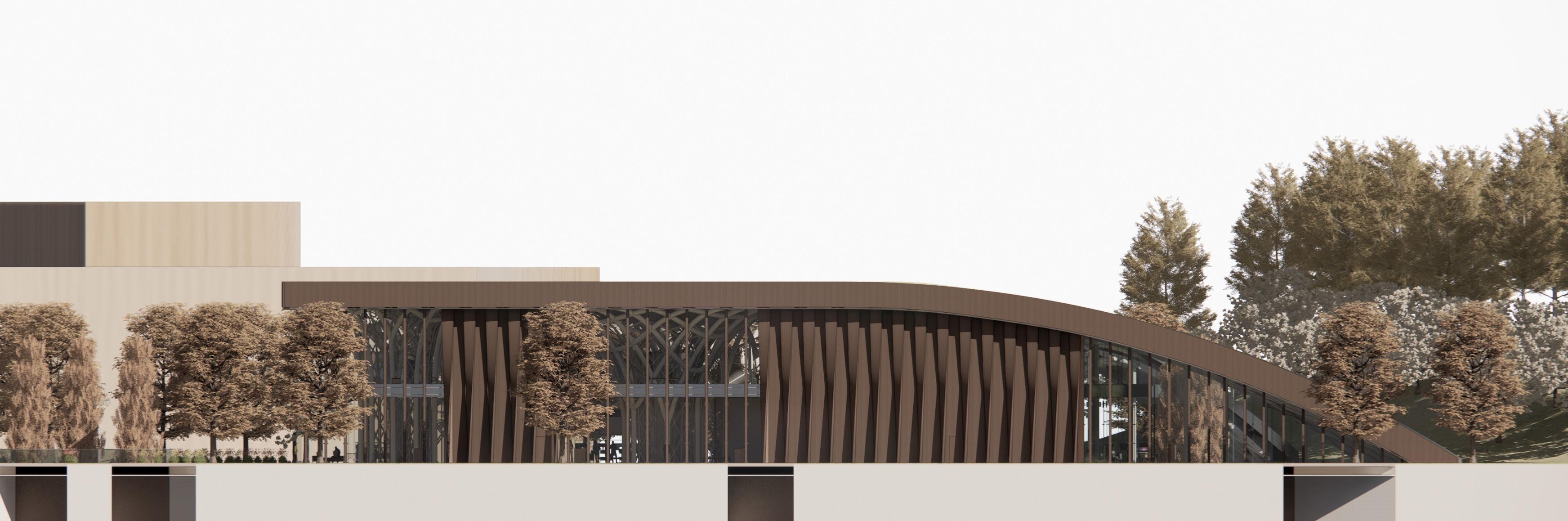
NGM, MIND MILAN| Museum/Research center
**Nominated for Thesis of the year politecnico di milano 2022
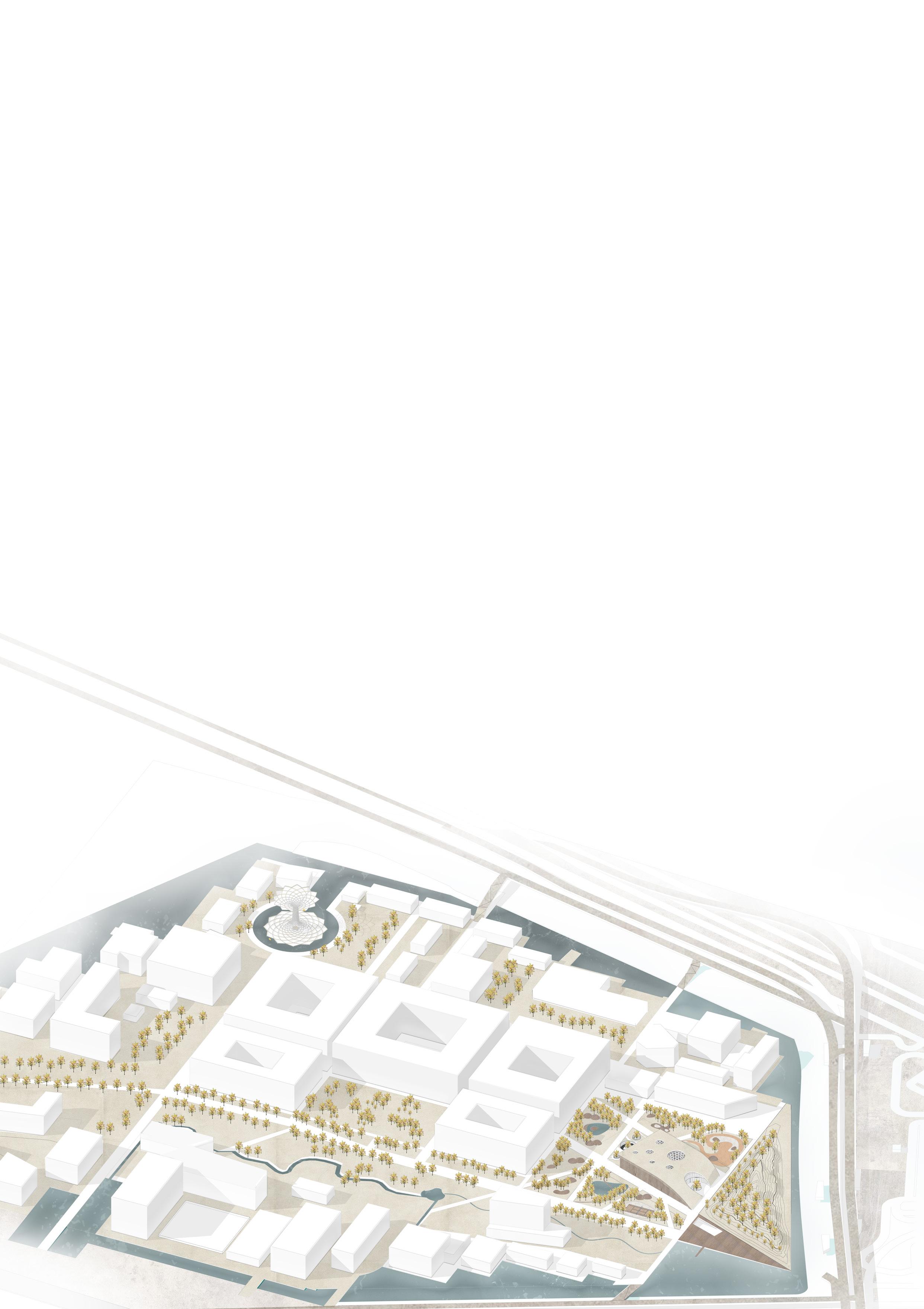
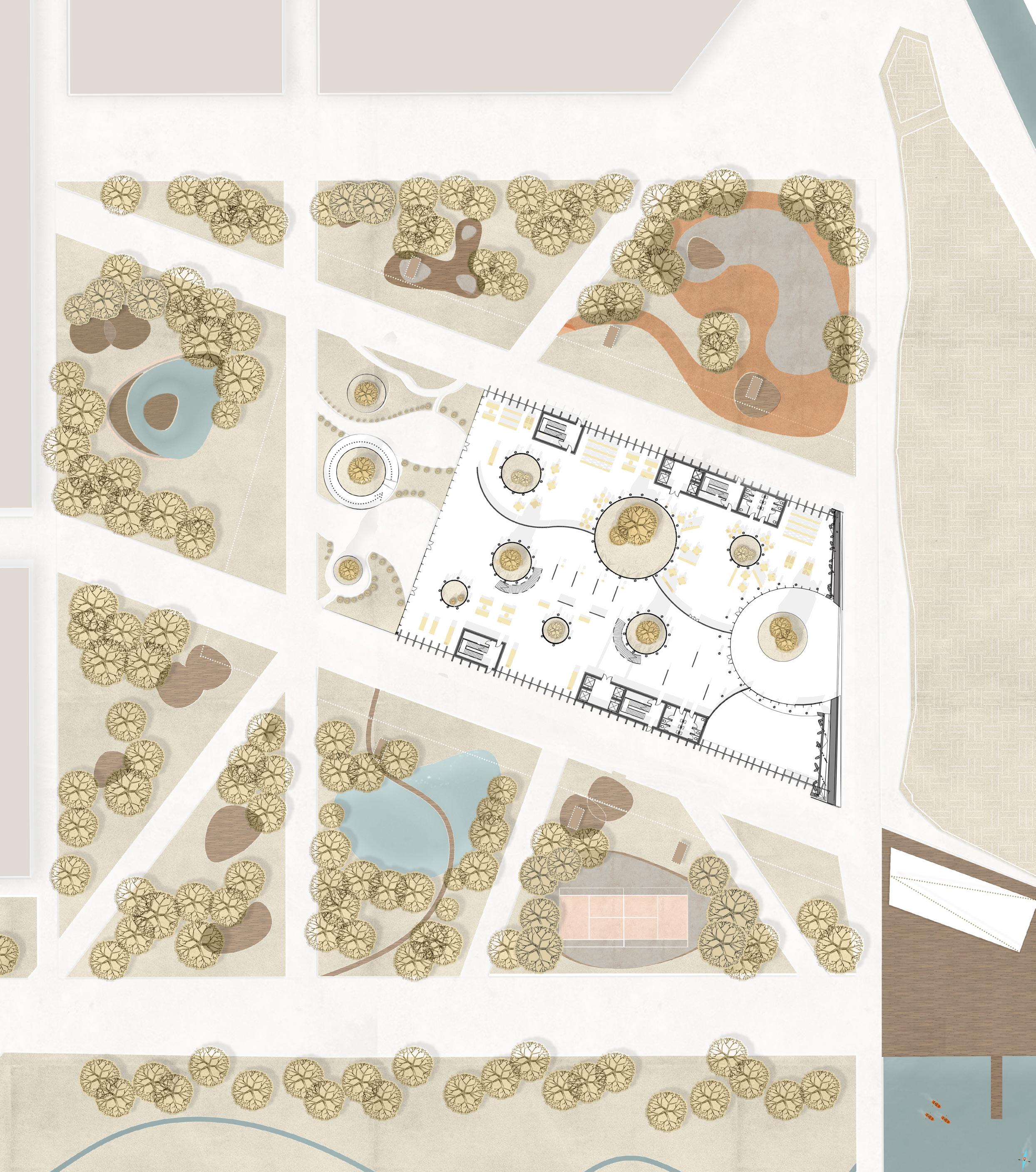
RELAX ATION AREAS
PIAZZA
SMART TOTEM
ATION AREAS
AREAS
SMART TOTEM
URBAN LAKE
SMART TOTEM
SKATING RANGE
SMART TOTEM
TOTEM
SMART TOTEM
TENNIS COURT
WATER
RELAXATION
RELAX
WATER SPORT
SMART
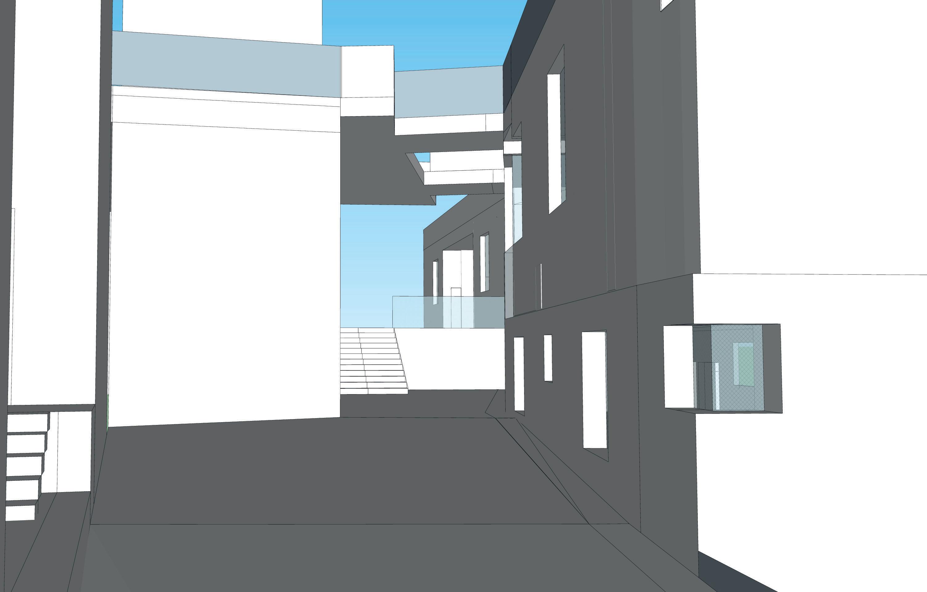
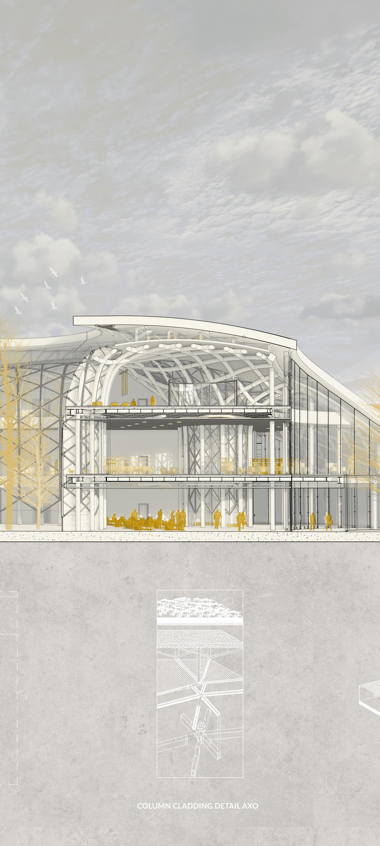
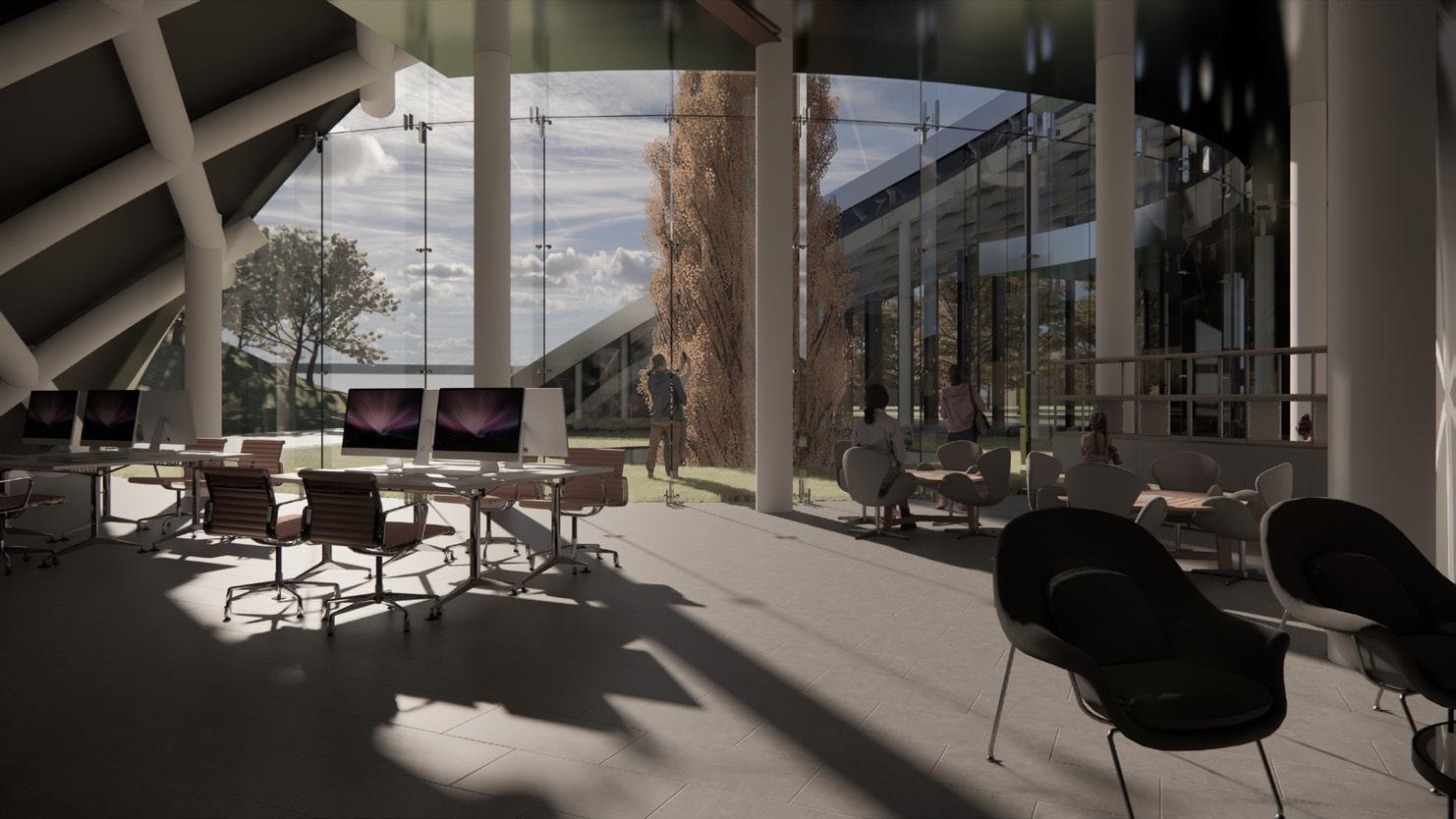
Laboratory view
Open work spaces
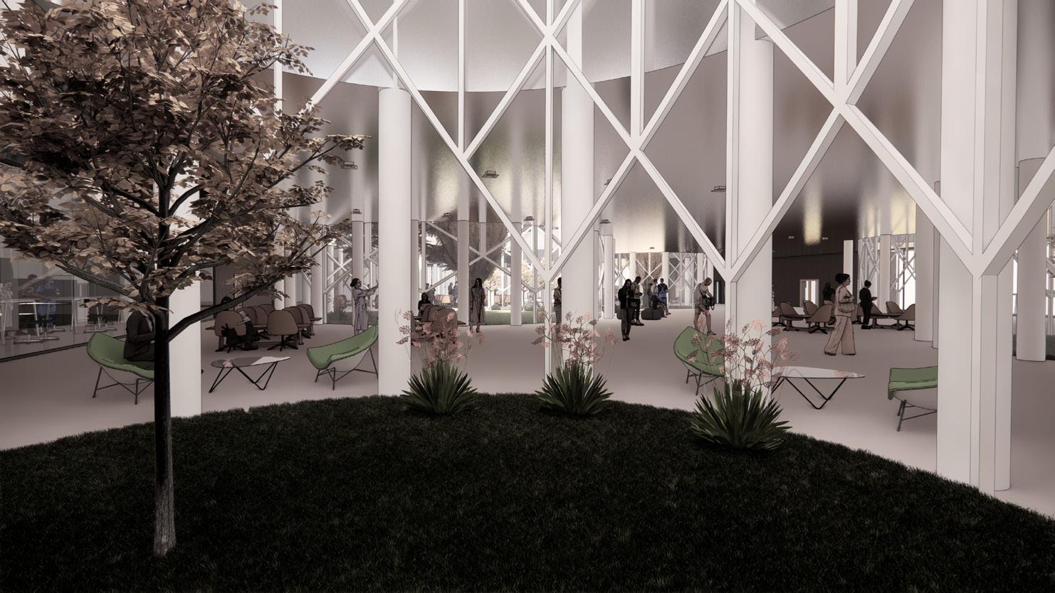
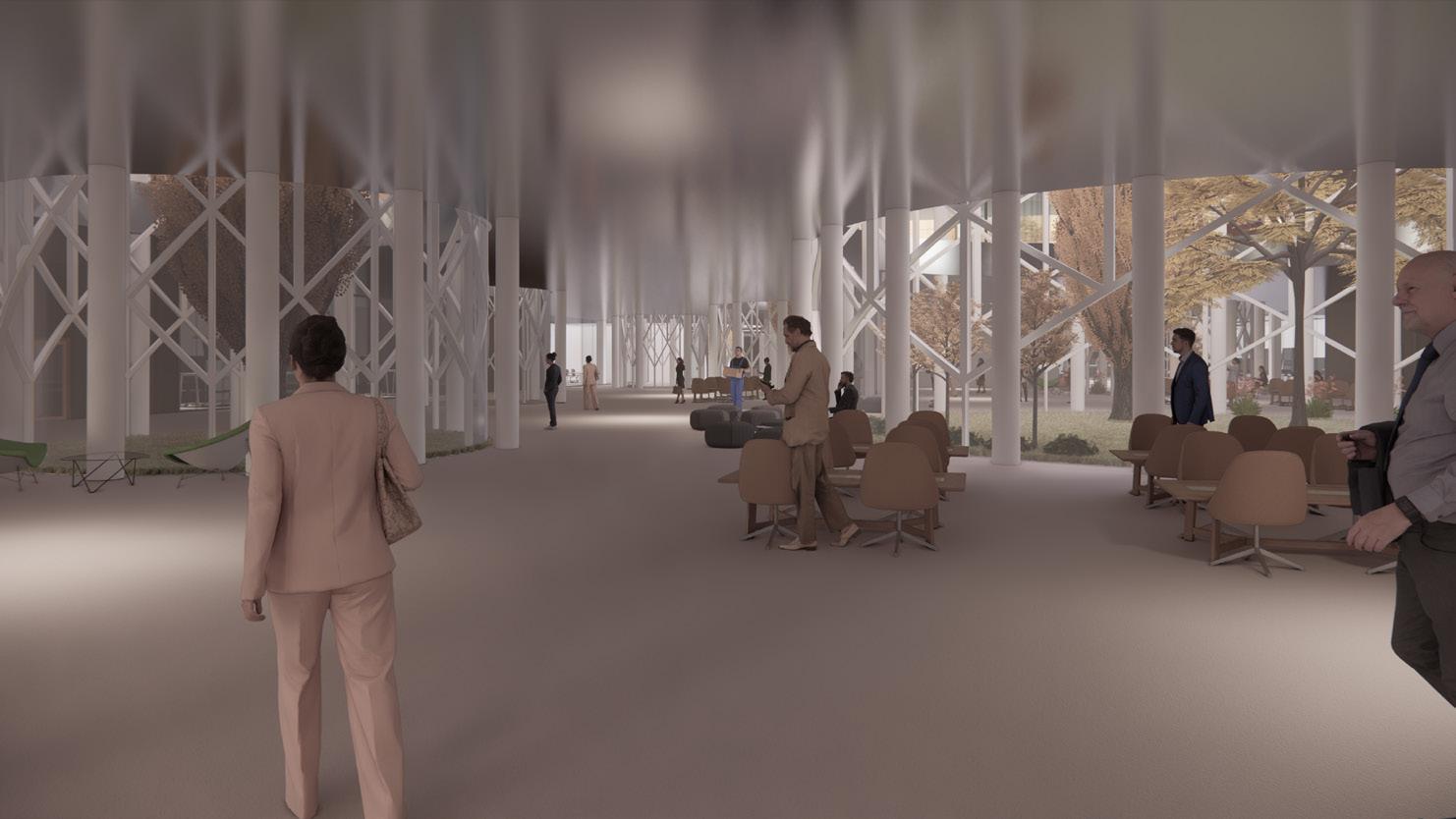
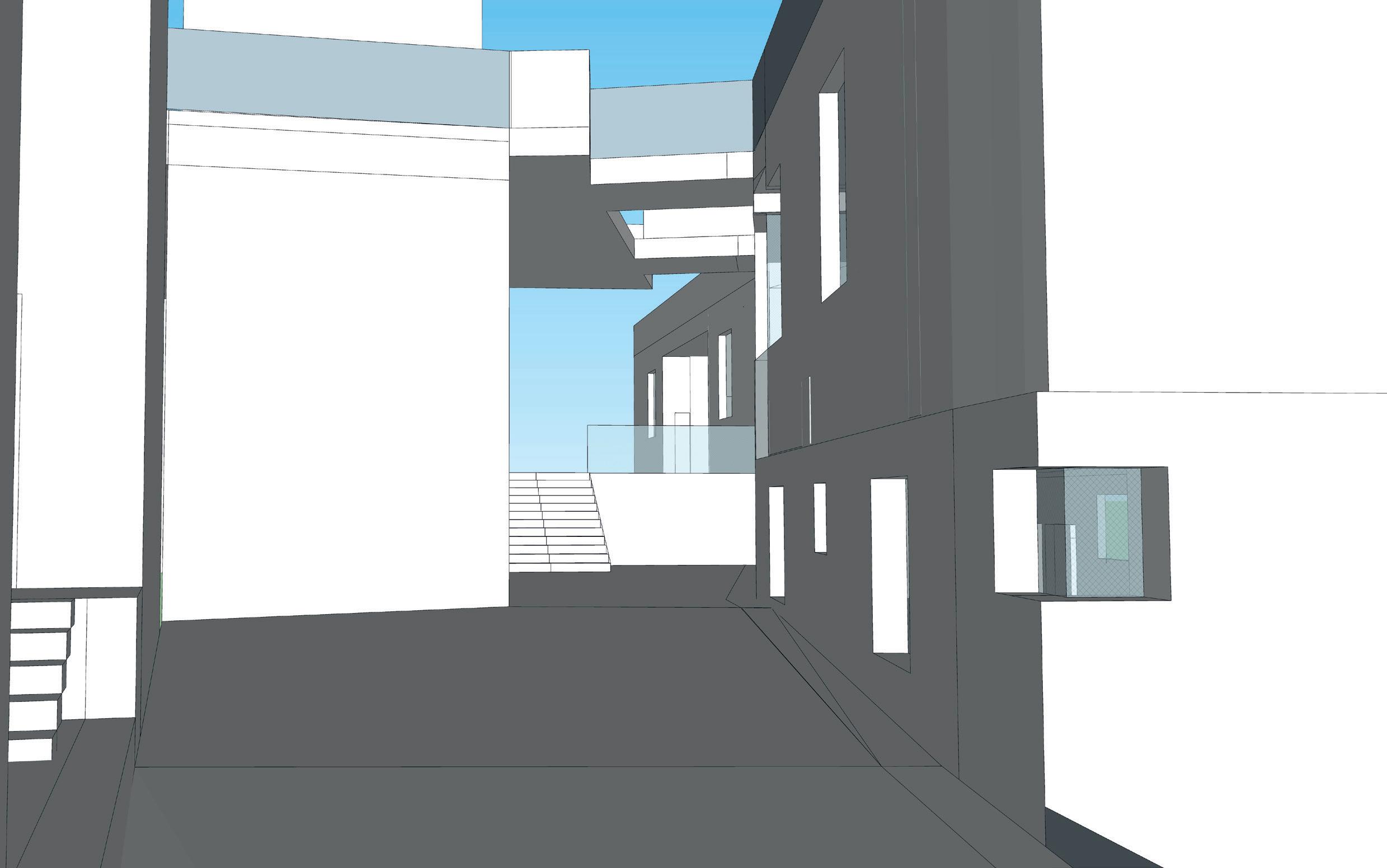
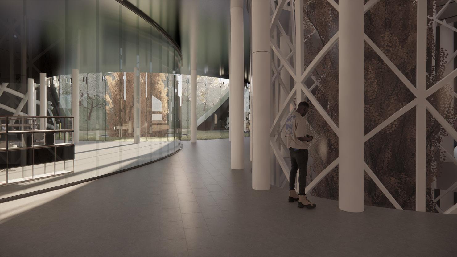
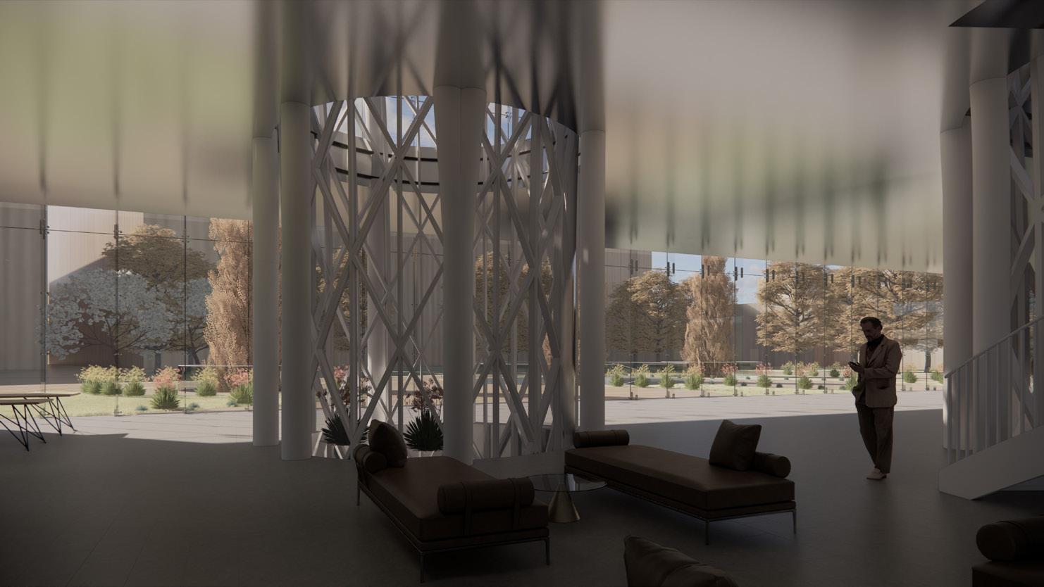
Perspective from the courtyards
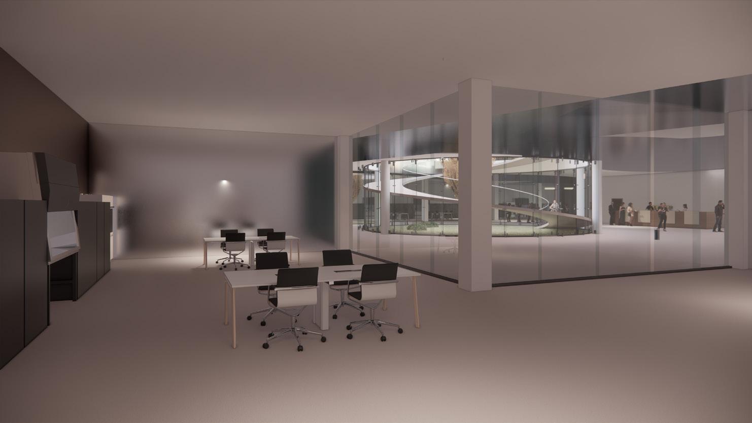
rooms and services

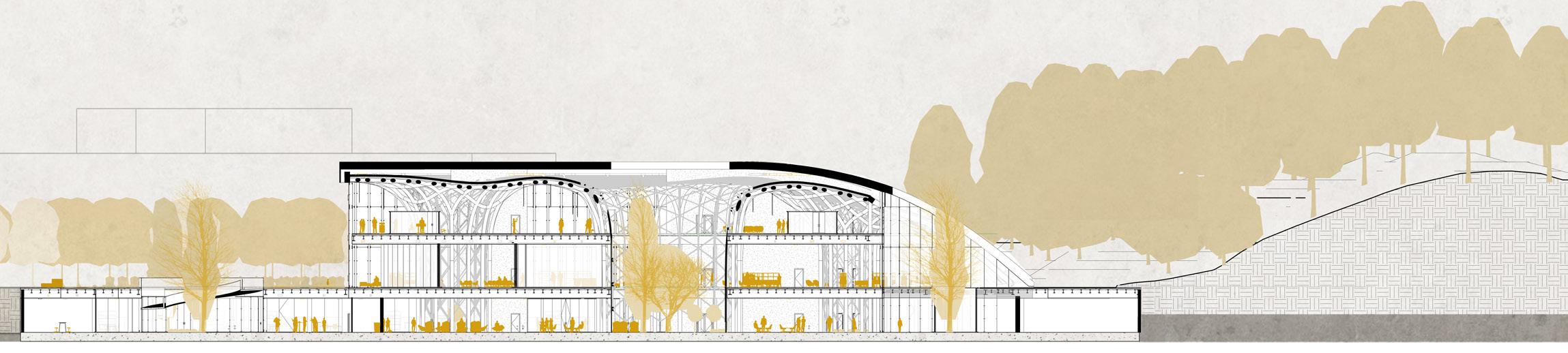
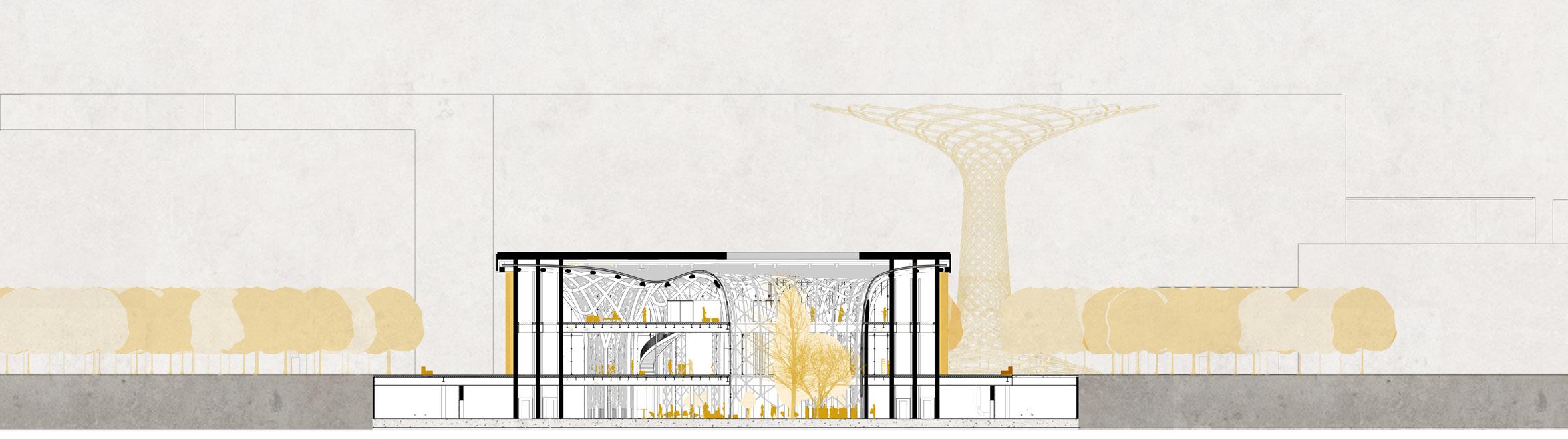
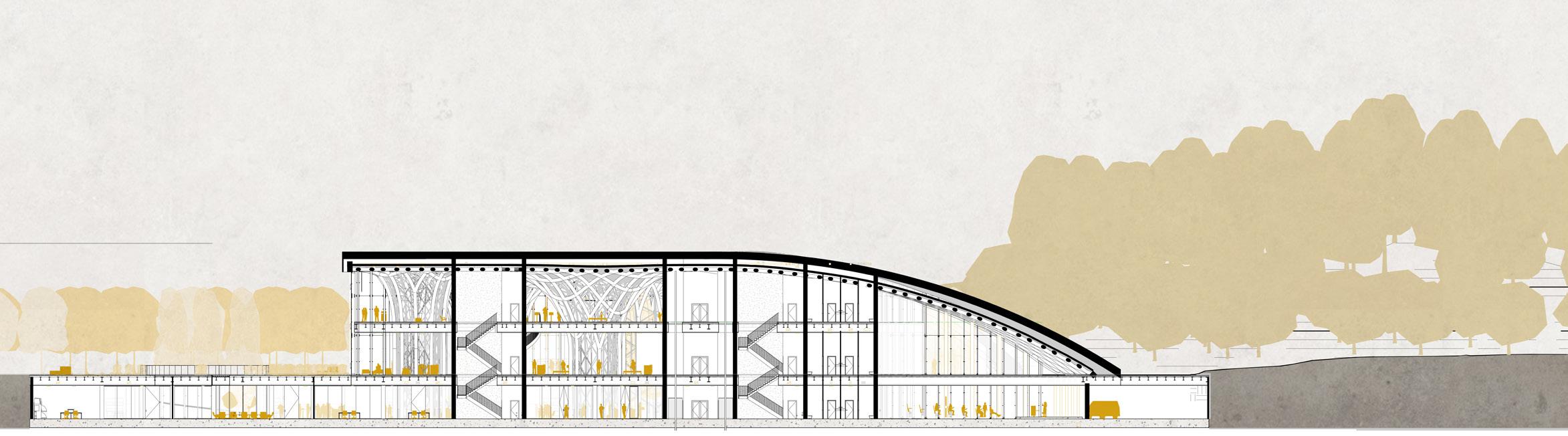
SECTION A-A’ 1:1000 Technical
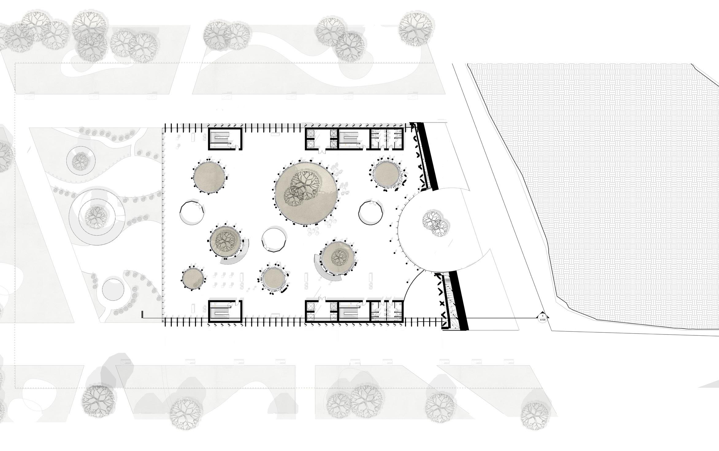
UNDERGROUND PLAN 1:1000 PROJECT PLANS&SECTION
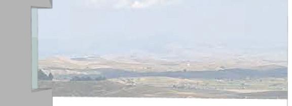
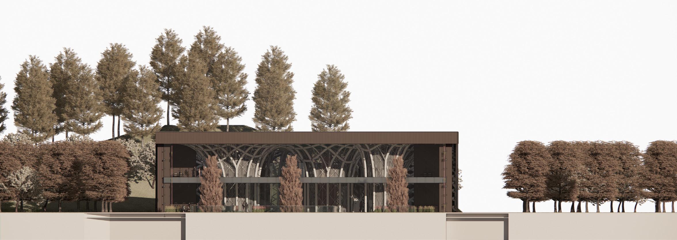
 Hill side view
Main entrance view Library hill view
Hill side view
Main entrance view Library hill view
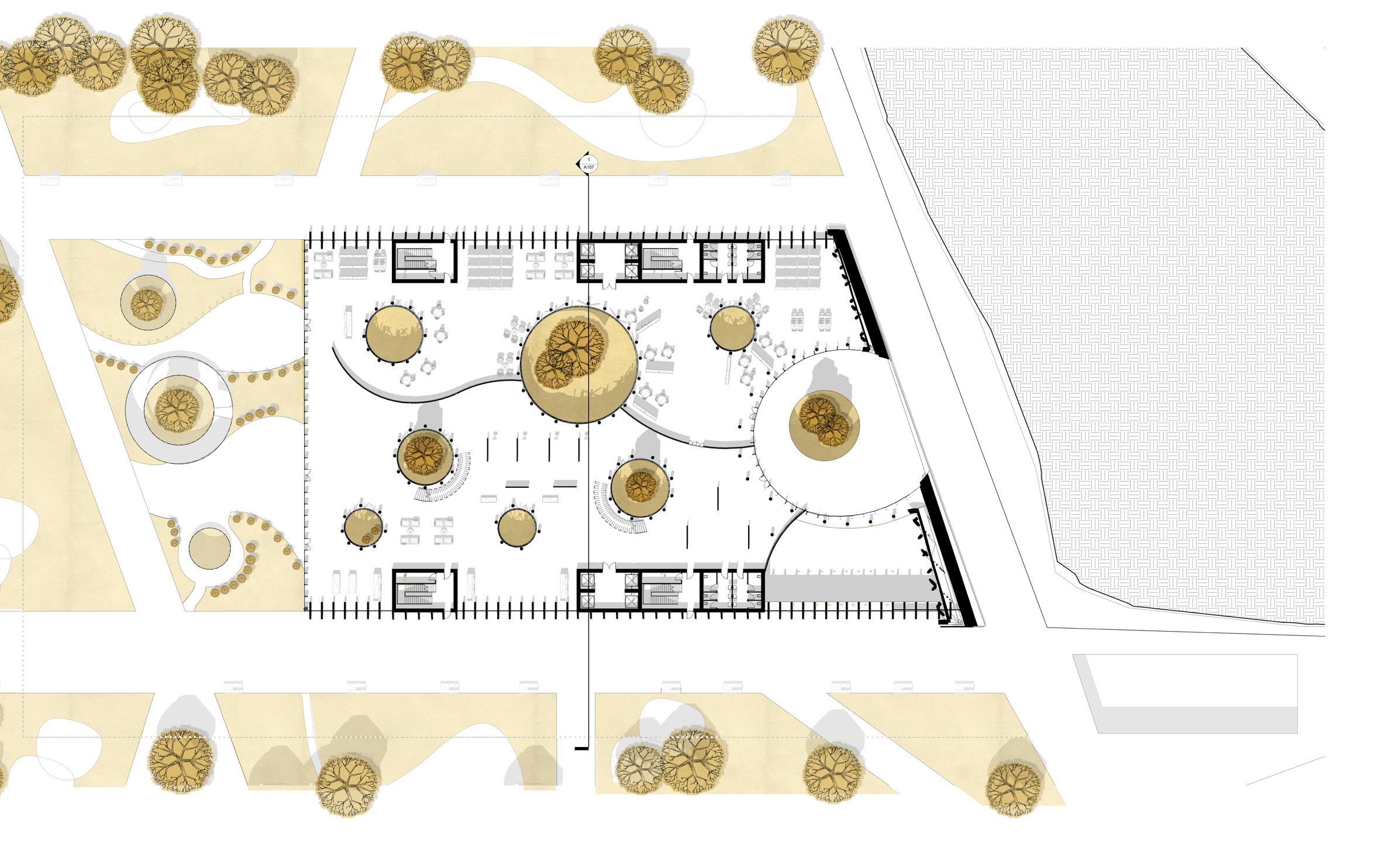
SECTION A-A’ 1:1000 GROUND PLAN 1:1000 PROJECT PLANS&SECTION
Emergency exit
 Exhibition view
Exhibition
floor
SECTION C-C’ 1:1000 FIRST FLOOR PLAN 1:1000 VR rooms
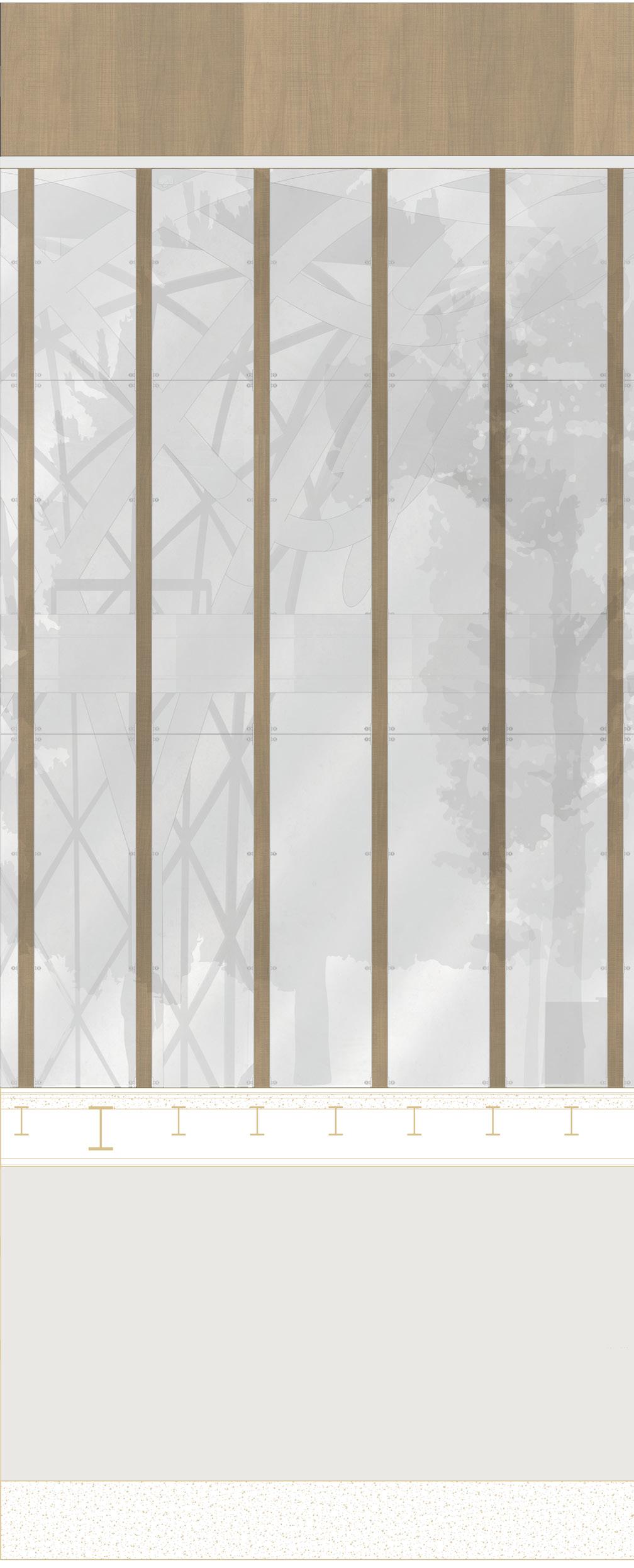


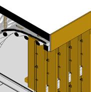
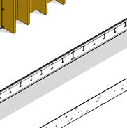
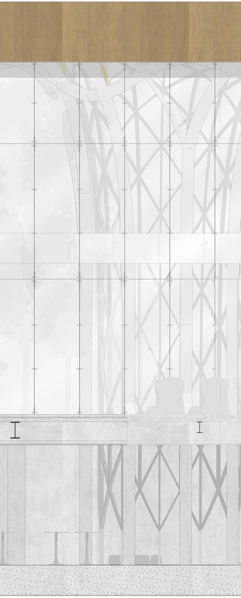
FACADE STRIGHT LOUvERS 1:100 I eLeRoo +13800 +6000 Groundfloor 0 16 95 120 500 335 86 285 70 100 550 300 200 100 127 125 500 335 86 11 72 15 51 124 330 505 86 8016 44 32 140 Louv1 T1 T2 215 1680 116 60 40 Crt.W1 Sub Geo1 Geo2 TP1 S.mem T.Insu V.bar Corr+scr W.mem S.lay Pav Scr Geo1 Geo2 S.mem T.insu Corr+scr Sp2 Sp1 Pav1 RF Corr+scr IPE 330 200 HEB 550 distance: 80 cm IPE 500 IPE 500 FACADE STRIGHT LOUVERS Detail 1:10 4 5 6 7 8 9 10 A B C D E F G H Roof Level +13800 1st Level +6000 A12 7 Groundfloor Level 0 1st Level +6000 Roof Level +13800 3 2 1 20 L9 7 L10 7 L10 7 A12-14 7 A15-17 8 Louv1 Crt.W1 Louv2 C.Alu Louv1 T1 T2 1680 116 60 40 1340 1340 1340 Crt.W1 Louv1 Louv2 W3 Sub Geo1 Geo2 TP1 S.mem T.Insu V.bar Corr+scr W.mem S.lay Sp2 Sp1 HEB 550 distance: 80 cm Cod. Technical Elem. Material Dim.s MATERIAŁ DESIGN FACADE ANALYSIS
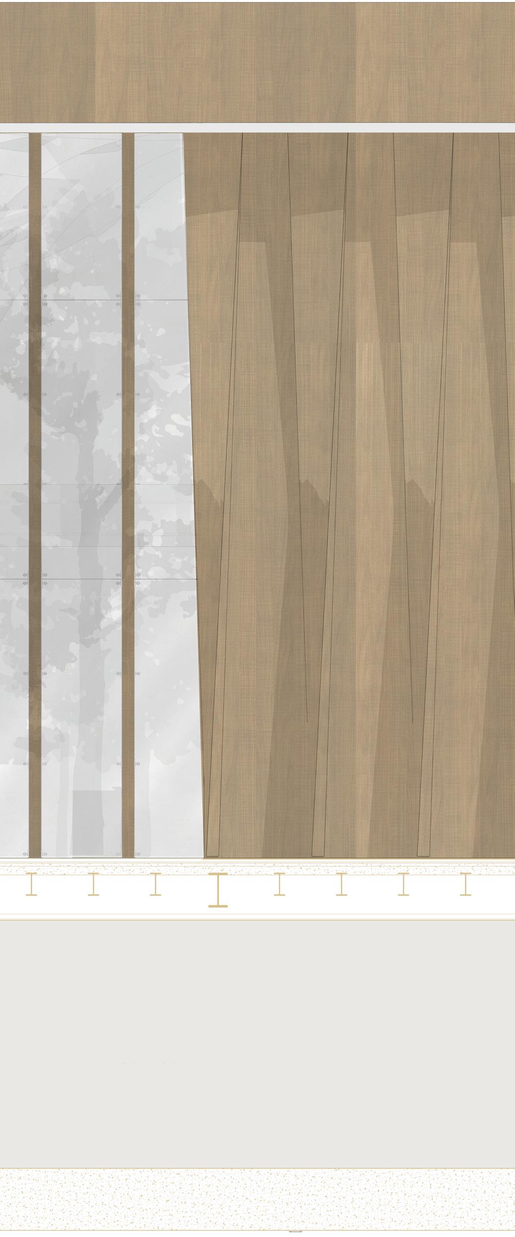
STRUCTURAL GLASS FACADE Detail 1:10 LR +13800 Level +6000 Groundfloo 0 Sub Geo1 Geo2 TP1 S.mem T.Insu V.bar Corr+scr W.mem S.lay Pav Scr Geo1 Geo2 S.mem T.insu Corr+scr Sp2 Sp1 Pav1 RF Corr+scr 16 95 120 500 335 86 22 125 125 500 335 86 11 7215 51 124 330 505 86 80 16 44 32140 T2 215 1680 116 60 40 T1 IPE 500 IPE 500 IPE 330 300 550 HEB 550 500 200200 800 300 550 HEB 550 500 200 L.gla 75 75 135 75 75 7 14 7 100 connecting oticplacode fin connecting bolt Em.p welding oticplacode connecting bolt L.Gla 30042 FACADE STRIGHT LOUVERS Detail 1:10 FACADE STRIGHT LOUvERS 1:20 5 6 7 8 9 10 A B C D E F G H Roof Level +13800 1st Level +6000 A12 7 Groundfloor Level 0 1st Level +6000 Roof Level +13800 3 2 1 20 L9 7 L10 7 L10 7 A12-14 7 A15-17 8 Louv1 Crt.W1 Louv2 C.Alu Louv1 T1 T2 1680 116 60 40 1340 1340 1340 Crt.W1 Louv1 Louv2 W3 Sub Geo1 Geo2 TP1 S.mem T.Insu V.bar Corr+scr W.mem S.lay Sp2 Sp1 Cod. Technical Elem. Material Dim.s MATERIAŁ DESIGN FACADE ANALYSIS


FACADE STRIGHT LOUBERS 1:100 FACADE TWISTED LOUvERS Detail 1:10 Roof Level +13800 1st Leve +6000 0 16 95 120 500 335 86 22 128 125 500 335 86 11 7215 51 124 330 505 86 80 16 44 32140 Louv2 T1 T2 215 1680 116 60 40 C.Alu RW.insu Sub Geo1 Geo2 TP1 S.mem T.Insu V.bar Corr+scr W.mem S.lay Pav Scr Geo1 Geo2 S.mem T.insu Corr+scr Sp2 Sp1 Pav1 RF Corr+scr IPE 330 IPE 500 W2 IPE 500 5 6 7 8 9 10 A B C D E F G H Roof Level +13800 1st Level +6000 A18 9 Groundfloor Level 0 1st Level +6000 Roof Level +13800 3 2 1 L9 7 L10 7 A1 3 A1 3 Sub Geo1 16 95 120 500 335 86 80 16 44 32140 T2 215 T1 300 550 HEB 550 500 200 Crt.W2 400 1500 1500 42 TP1 Cod. Technical Elem. Material Dim.s Sub Substrate W=300 mmCultivation substrate FERTILROOF LightTer MATERIAŁ DESIGN FACADE ANALYSIS
MATERIAL TABLE
FACADE ANALYSIS
Cod. Technical Elem. Material Dim.s
Sub Substrate W=300 mmCultivation substrate FERTILROOF LightTer Extensive type, with prevalent mineral composition, complying with the requirements of the UNI11235: 2015
Draining geocomposite geomat coupled with non-woven geotextile W=20 mm
W=3 mm
Geo1 Draining geocomposite Needle-punched and heat-set non-woven geotextile (GTX-N) FERTILROOF Stratu 500 to protect the element
TP1 Tubular profile 100x100 mmsteel
S.mem Synthetic membrane W=1.5 mmSingle-layer synthetic membrane made of homogeneous PVC-P obtained by coextrusion
T.insu Thermal insulation W=100 mmThermo insulating element Self-extinguishing sintered expanded polystyrene
V.bar Vapour barrier W=30 mmVapor barrier layer in waterproof class W1 (resistance to a water column pressure of 20 cm for a duration of 2 hours) in accordance with the provisions o UNI EN 13984 and UNI EN 13859-1, with guaranteed even afte the UV IR aging test required by UNI EN 1296 and UNI EN 1297.
S.lay Slope layer W=100 mmSlope layer according to UNI 8627
W.mem Waterproof membrane W=20 mm Corr+scr Corrugated sheet + concrete screed W=140 mmconcrete, cast in situ.+galvanized steel
Sp1S teel profile 1 W=50 mmsteel
Sp2S teel profile 2 W=50 mmsteel
T1 Tube 1, primary structure D=40 cm R=20 cm steel
T2 Tube 2, primary structure D=20 cm R=10 cm steel
Pav
Geo1 Scr
Pavement Screed
Ceramic Concrete
W=7 cm W=6 cm
Pav1 Pavement 1 Ceramic W=12 cm RF Raised floor
Louv2 Louver 2, twisted aluminum rectangular profile with wood grain powder coat finish C.Alu Composite Aluminum Panel ACP with wood grain powder coat finish
RW.insu Rock mineral wool insulation W=10 cm
W2 Wall 2, concrete core reinforced concrete, C25 W=40 cm H=17 m
IPE 500 Secondary beam steel, IPE 500 H=50 cm W=20 cm
IPE 330 Secondary beam steel, IPE 330 H=33 cm W=16 cm
Sub Substrate W=300 mmCultivation substrate FERTILROOF LightTer Extensive type, with prevalent mineral composition, complying with the requirements of the UNI11235: 2015
Geo1
Draining geocomposite geomat coupled with non-woven geotextile W=20 mm
W=3 mm
Geo1 Draining geocomposite Needle-punched and heat-set non-woven geotextile (GTX-N) FERTILROOF Stratu 500 to protect the element
TP1 Tubular profile 100x100 mmsteel S.mem Synthetic membrane W=1.5 mmSingle-layer synthetic membrane made of homogeneous PVC-P obtained by coextrusion
T.insu Thermal insulation W=100 mmThermo insulating element Self-extinguishing sintered expanded polystyrene
V.bar Vapour barrier W=30 mmVapor barrier layer in waterproof class W1 (resistance to a water column pressure of 20 cm for a duration of 2 hours) in accordance with the provisions of UNI EN 13984 and UNI EN 13859-1, with guaranteed even afte the UV IR aging test required by UNI EN 1296 and UNI EN 1297.
Louv1 Louver 1, straight louver T=160 mm, H=12 m structural steel louvers, powder coated wood grain finish
Crt.W1 Curtain wall 1 T=42 mmstructural steel
louvers, powder coated wood grain finish Geo1 Sub Substra e W 300 mmCultivation substrate FERTILROOF LightTer Extensive type, with prevalent mineral composition, complying ith the require ent of the UNI11235: 2015 Draining geocomposite geomat coupled with non- oven geotextile W 20 mm Geo1 Draining geocomposite Needle-punched and heat-set non-woven geotextile (GTX-N FERTILROOF Stratum 500 to protect th element W 3 mm TP1 Tubular profile 100x100 mmsteel S.mem Synthetic membrane W=1 5 mmSingle-layer synthetic membrane made of homogeneous PVC-P obtained by coextrusion T insu Thermal insulation W 100 mmTher o insulating element Self-extinguishing sintered expanded polystyrene V.bar Vapour barrier W=30 mmVapor barrier layer in aterproof class W1 (resistance to a water column pressure of 20 cm for a duration of 2 hours) in accordance with the provisions of UNI EN 13984 and UNI EN 13859-1, with guaranteed even afte the UV IR aging tests required by UNI EN 1296 and UN EN 1297. L gla insula ing empered glass 10 mm +1 52PVB +10mm empered glass L Gla lamina ed tempered glass 10mm + 12A + 10mm lamina ed glass


Raft Foundation -7000 Excavation -7300 Underground Level -5000 Groundfloor Level 0 Level1st +6000 Roof Level +13800 3 2 1 0 T1 S1 S5 S2 S2 T1 IPE 500 HEB 550 T2 S4 Cod. Technical Elem.M aterial Dim. TP1 Tubular profile 100x100 mm Gla.p double glazed glass Af1 T=50 mm aluminum Glass panel Aluminum frame 1 T=120 mm SF2 steel T=20 mmSteel frame 2 SF1 T=160 mmSteel frame 1 T2 steelTube 2, secondary structure R=20 cm C.Alu ACPComposite Aluminum Panel T=50 mm COLUMN CLADDING DETAIL 1:100
STRUCTURAL DRAWINGS
Steel pipes 400 mm R
Framing system IPE500
Shear walls 400 mm Underground steal columns HEA500/300
B C D E F G H I J 21 3 4 5 6 7 8 9 Pav2 Scr2 Pop Sct V.Cl Cod. Fsl W.mem Snd Hc W1 Insu 0 202 100 1000 390 160 160 85 20 165 200 200 200 200 200 200 30050 50 W2 W2 200 200 200 200 300 50 50 200 0 400 0 Raft Foundation -7000 Underground Level -5000 Raft Foundation -7000 Underground Level -5000 200 200 200 200 200 200 200 90 200 200 200 200 200 90 90 90 1000 50 50 Pav2 Scr2 Pop Sct Fsl V.Cl Rft.F Rft.F W2 Rft.F Hc Snd W.mem A3 4 A4 4 A5 4 Pav2 Scr2 Pop Sct V.Cl Cod. Technical Elem.M aterial Elem Cod. Dimensions Pavement Screed Extruded polysterene panel Isocal formworks screed with transit fo r systems cavity with Iglu’® Plus Finishing slab Ceramic Concrete Polysterene Concrete Reinforced Concrete C25 W=12 cm W=6 cm W=10 cm W=8 cm W=27 cm W=5 cmFsl membrane W= negligibleW.me m Snd Sand layer Sand W=10 cm Hc Hard core layer Concrete W=20 cm Wall 1, retaining wall W= 40 cm H=5 m W1 W=10 cmInsu Reinforced Concrete C25 H=1 mC25Reinforced Concrete Underground columns Foundation 1:50
21 3 4 5 6 7 8 9 A B C D E F G H I J 21 3 4 5 6 7 8 9 20 Raft Foundation -7000 Excavation -7300 Underground Level -5000 Raft Foundation -7000 Excavation -7300 Underground Level -5000 A6 5 A7 5 A8 5 A9 5 20 2 0 0 200 100 1000 90 90 200 200 1604 160 85 20 110 45 1560 800 T1 Sct 200 100 1000 90 90 200 200 390 160 160 85 20 Pav2 Scr2 Pop Sct V.Cl Cod. Pav2 Scr2 V.Cl Snd Hc Sct V.Cl Snd Hc Pop Pop Pav2 Scr2 C1 C1 Pl.C T1 Pl.T 800 W.memW.mem Fsl W.mem Snd Hc Sub Geo1 T.insu Geo2 V.bar S.lay Sub Geo1 Geo2 T.insu S.lay Pl.T T1 Pl.C C1 1100 1100 110 110 2 1100 110 Pl.T Pl.C 715 715 Fsl Fsl165 230 250 230 390 165 230 250 230 Rft.F Rft.FRft.F Paramitric columns Foundation1:50
21 3 4 5 6 7 8 9 10 A B C D E F G H I J 21 3 4 5 6 7 8 9 10 Raft Foundation -7000 Excavation -7300 Underground Level -5000 A11 5 0 200 100 1000 390 160 160 85 20 Pav2 Scr2 Pop W.mem Hc Snd K K 1 Sct Fsl V.Cl W1 Insu Dr 200 200 200 200 200 200 200 200 270 45 W.mem 165 A10 5 200400 W1 200 300 50 50 200 200 135 50 50 400 440 Pav2 Scr2 Pop Sct V.Cl Cod. Fsl W.mem Snd Hc W1 Insu Dr Rft.F PERIMETER COLUMNS FOUNDATION1:50 Snd Sand layer Sand W=10 cm Hc Hard core layer Concrete W=20 cm Substrate H=6 cmSub Draining geocomposite H=2 cmGeo1 H=3 m mGeo2 H=10 cmT.insu Draining geocomposite Slope layer H=10 cmS.lay Slope layer according to UNI 8627 Pl.T Column plate Steel R=60 cm T1 Tube 1 Steel D=40 cm, r=20 cm Pl.C Column plate Steel W=20 cm, H=20 cm C1 Column 1 Steel HEA 500 H=1 mReinforced Concrete C25 Cod. Technical Elem. Material Elem Cod. Dimensions
Foundation plan 1:2000
Dimensions
floor structure
Dimensions
A B C D E F G H I J K L M N 21 3 4 5 6 7 8 9 10 11 12 13 14 15 16 17 18 19 20 O Prof. Massimiliano Nastri Architectural Design Studio for Complex Constructions 2 (A.Y. 2021-2022) Students: Eden Nimni, Marianne Esses, Bita Rostamiyar Technical Drawings: Foundation localization drawing L1 Group: 11 Date: 22.06.2022 1Page: 1 2 3 4 5 6 7 8 9 10 11 12 13 14 15 16 17 18 19 20 1 2 3 4 5 6 7 8 9 10 11 12 13 14 15 16 17 18 19 20 A B C D E F G H I J K A B C D E F G H J K W1 W2 W1 W1 W2W1 W1 C1 C1 C1 C1 C1 C1 C1 C1 C1 C1 C1C1 C1 C1 C1 C1 C1 C1 C2 C2 C2C2 C2 C2 C2 C2 C2 C2 C2 C2 C2 C2T1 T1 T1 T1 C2C2 C2 8000 8000 8000 8000 8000 8000 8000 8000 8000 8000 8000 8000 8000 8000 8000 8000 8000 8000 8000 112000 152000 8000 10730 8000 8000 8000 8000 8000 8000 8000 8000 8000 80000 3530 1640 2500 2670 2750 2500 2750 4980 3020 5170 4980 3020 4000 4000 4000 4000 3400 2920 3400 2920 4000 4000 2820 2930 2930 2830 35301640 2500 2670 2750 2500 2750 4980 3020 5170 4980 3020 R6720 R3850 R3850 R5870 W1 W2 W1 W1 2830 2080 C2 C2 C2 1606 1501 A4 1 L8 3 L8 3 L6 3 L6 3 C1 C2 C3 T1 W1 W2 IPE 500 IPE 330 HEB 550 Cod. column 1 column 2 column 3 tube 1 wall 1, retaining wall wall 2, concrete core secondary beam secondary beam primary beam Technical Element steel steel Concrete Material C25 C25 IPE 500 IPE 330 HEB 550 Element Code HEA 500 HEA 500 HEA 300 d = 40 cm, r = 20 cm
Concrete steel steel steel steel steel w = 40 cm, r = 5 m w = 40 cm, r = 17 m H = 55 cm, W = 21 cm H = 50 cm, W = 20 cm H = 33 cm, W = 16 cm
C1 C2 C3 T1 W1 W2 IPE 500 IPE 330 HEB 55 0 Cod. column 1 column 2 column 3 tube 1 wall 1, retaining wall wall 2, concrete core secondary beam secondary beam primary beam Technical Element steel steel Concrete Material C25 C25 IPE 500 IPE 330 HEB 550 Element Code HEA 500 HEA 500 HEA 300 d = 40 cm, r = 20 cm
Concrete steel steel steel steel steel w = 40 cm, r = 5 m w = 40 cm, r = 17 m H = 55 cm, W = 21 cm H = 50 cm, W = 20 cm H = 33 cm, W = 16 cm Ground
1:2000 Sectionl8/3 1:2000 Prof. Massimiliano Nastri Architectural Design Studio for Complex Constructions 2 (A.Y. 2021-2022) Students: Eden Nimni, Marianne Esses, Bita Rostamiyar A B C D E F G H J K L M N 21 3 4 5 6 7 8 9 10 11 12 13 14 15 16 17 18 19 O Technical Drawings: Structural Sections L6 and 1st Level Structural Plan L5 Structural Louver Detail A1-2 Group: 11 Date: 22.06.2022 Page: 5 6 7 8 9 10 11 12 13 14 5 6 7 8 9 10 11 12 13 14 C D E F G H C D E F G H I A B C D E F G H I J K 1 2 3 0 5 6 7 8 9 10 11 12 13 144321 15 16 17 18 8000 8000 8000 8000 8000 8000 8000 8000 8000 -7000 Excavation Underground Level L8 3 L6 3 L6 3 L8 3 1 2 3 0 Raft Foundation Excavation 1st Level +13800 A2 3 L8 3 L7 3 L6 3 A1 3 1164 10 x 1164 mm 290 1500 160 120x200x10 rectangular steel tubes 120x200x10 rectangular steel tubes Aluminum composite panel with a wood grain pattern finish 8000 8000 8000 8000 8000 8000 48000 72000 80000 8000 8000 8000 8000 8000 8000 8000 8000 8000 8000 8000 8000 8000 8000 8000 8000 8000 136000 C2 C2 C2 C2 T1 T1 C2 C2 T1 T1 T1 T1 HEB 550 HEB 550HEB 550 HEB 550 HEB 550 HEB 550 HEB 550HEB 550 HEB 550 HEB 550 HEB 550 IPE 500 HEB 550 IPE 500 IPE 500 HEB 550 IPE 500 IPE 500 HEB 550 IPE 500 HEB 550 IPE 500 IPE 500 HEB 550 IPE 500 IPE 500 HEB 550 IPE 500 IPE 500 IPE 500 HEB 550 HEB 550 HEB 550 HEB 550 HEB 550 W2 W2 W2W2 W2 W2 T1 T1 T1 W2 W2 W2 W2 W1 W1W1 W2W2W2 C1 C2 C3 T1 W1 W2 IPE 500 IPE 330 HEB 550 Cod. column 1 column 2 column 3 tube 1 wall 1, retaining wall wall 2, concrete core secondary beam secondary beam primary beam Technical Element steel steel Concrete Material C25 C25 IPE 500 IPE 330 HEB 550 Element Code HEA 500 HEA 500 HEA 300 d = 40 cm, r = 20 Dimensions Concrete steel steel steel steel steel w = 40 cm, r = 5 w = 40 cm, r = 17 H = 55 cm, W = H = 50 cm, W = H = 33 cm, W = Prof. Massimiliano Nastri Architectural Design Studio for Complex Constructions 2 (A.Y. 2021-2022) Students: Eden Nimni, Marianne Esses, Bita Rostamiyar 21 3 4 5 6 7 8 9 10 11 12 13 14 15 16 17 18 19 A B C D E F G H J K L M N 21 3 4 5 6 7 8 9 10 11 12 13 14 15 16 17 18 19 O Technical Drawings: Groundfloor Level Structural scale1:200 Group: 11 Date: 22.06.2022 Page: 1 2 3 4 5 6 7 8 9 10 11 12 13 14 15 16 17 18 19 20 1 2 3 4 5 6 7 8 9 10 11 12 13 14 15 16 17 18 19 20 A B C D E F G H I J K A B C D E F G H J K C1 C1 C1 C1 C1 C1 C1 C1 C1 C1 C1 C1 C1 C1 C1 C1 W1 C2 C2 C2 C1 C1 C1 C1 C1 C1 C1 C1 C2 C2 C2 C1 C1 C1 C2 C2 C2 C2 C2 C2 C2 C2 C2 C2 C2 C2 C2 C2 W1 8000 8000 8000 8000 8000 8000 8000 8000 8000 8000 8000 8000 8000 8000 8000 8000 8000 8000 8000 112000 152000 8000 10730 80000 C2 C2 C2 8000 8000 8000 8000 8000 8000 8000 8000 8000 C1 T1 T1 T1 L5 2 L8 3 L8 3 L6 3 L6 3 IPE 330 HEB 550 HEB 550 HEB 550 HEB 550 HEB 550 HEB 550 HEB 550 HEB 550 HEB 550 HEB 550 IPE 330 IPE 330 IPE 330 HEB 550 HEB 550 HEB 550 IPE 330 IPE 330 IPE 330 HEB 550 HEB 550 HEB 550 IPE 330 IPE 330 IPE 330 IPE 330 IPE 330 IPE 330 IPE 330 IPE 330 IPE 330 HEB 550 HEB 550 IPE 330 IPE 330 HEB 550 HEB 550 IPE 330 IPE 330 HEB 550 HEB 550 IPE 330 IPE 330 HEB 550 HEB 550 IPE 330 IPE 330 HEB 550 HEB 550 IPE 330 IPE 330 HEB 550 HEB 550 IPE 330 IPE 330 HEB 550 HEB 550 IPE 330 IPE 330 HEB 550 HEB 550 IPE 330 IPE 330 HEB 550 HEB 550 IPE 330 IPE 330 HEB 550 HEB 550 IPE 330 IPE 330 HEB 550 HEB 550 IPE 330 IPE 330 HEB 550 HEB 550 IPE 330 IPE 330 HEB 550 HEB 550 IPE 330 IPE 330 IPE 330 HEB 550 HEB 550 IPE 330 IPE 330 HEB 550 HEB 550 IPE 330 IPE 330 HEB 550 HEB 550 IPE 330 IPE 330 HEB 550 HEB 550 IPE 330 IPE 330 HEB 550 HEB 550 IPE 330 IPE 330 HEB 550 HEB 550 IPE 330 IPE 330 HEB 550 HEB 550 IPE 330 IPE 330 HEB 550 HEB 550 IPE 330 IPE 330 HEB 550 HEB 550 IPE 330 IPE 330 HEB 550 HEB 550 IPE 330 IPE 330 HEB 550 HEB 550 IPE 330 IPE 330 HEB 550 HEB 550 IPE 330 IPE 330 HEB 550 HEB 550 IPE 330 HEB 550 HEB 550 HEB 550 HEB 550 HEB 550 HEB 550 HEB 550 HEB 550 HEB 550 HEB 550 HEB 550 HEB 550 HEB 550 HEB 550 HEB 550 HEB550 HEB 550 IPE 330 HEB 550IPE 330 HEB 550 IPE 330 HEB 550 IPE 330 IPE 330 HEB 550 HEB 550 HEB 550 HEB 550 HEB 550 HEB 550 HEB 550 HEB 550 HEB 550 HEB 550 HEB 550 HEB 550 HEB 550 HEB 550 HEB 550HEB 550 HEB 550 HEB 550 IPE 330 HEB 550 IPE 330 HEB 550 IPE 330 HEB 550 IPE 330 HEB 550 IPE 330 HEB 550 IPE 330 HEB 550 IPE 330 HEB 550 IPE 330 HEB 550 IPE 330 HEB 550 IPE 330 HEB 550 IPE 330 HEB 550 IPE 330 HEB 550 IPE 330 HEB 550 IPE 330 IPE 330 IPE 330 IPE 330 IPE 330 IPE 330 IPE 330 IPE 330 IPE 330 IPE 330 HEB 550 HEB 550HEB 550 HEB 550 HEB 550 HEB 550 HEB 550 HEB 550HEB 550 HEB 550 HEB 550 HEB 550 IPE 500 HEB 550 IPE 500 IPE 500 HEB 550 IPE 500 IPE 500 HEB 550 IPE 500 HEB 550 IPE 500 IPE 500 HEB 550 IPE 500 IPE 500 HEB 550 IPE 500 IPE 500 IPE 500 C1 C2 C3 T1 W1 W2 IPE 500 IPE 330 HEB 550 Cod. column 1 column 2 column 3 tube 1 wall 1, retaining wall wall 2, concrete core secondary beam secondary beam primary beam Technical Element steel steel Concrete Material C25 C25 IPE 500 IPE 330 HEB 550 Element Code HEA 500 HEA 500 HEA 300 d = 40 cm, r = 20 cm Dimensions Concrete steel steel steel steel steel w = 40 cm, r = 5 m w = 40 cm, r = 17 m H = 55 cm, W = 21 cm H = 50 cm, W = 20 cm H = 33 cm, W = 16 cm HEB 550 HEB 550 HEB 550 HEB 550 HEB 550
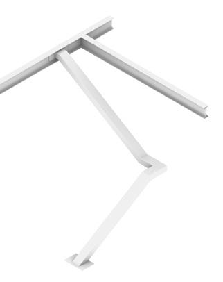
EXPLODED AXO. STRUCTURAL SUPPORTS Straight louvers serving as columns to provide extra support First floor plan 1:2000 Sectionl6/3 1:2000 Prof. Massimiliano Nastri Architectural Design Studio Complex Constructions 2 (A.Y. Students: Eden Nimni, Marianne 21 3 4 5 6 7 8 9 10 11 12 13 14 15 16 17 18 21 3 4 5 6 7 8 9 10 11 12 13 14 15 16 17 18 Technical Drawings: Structural 1st Level Structural Group: 11 Date: 22.06.2022 5 6 7 8 9 10 11 12 13 14 5 6 7 8 9 10 11 12 13 14 C D E F G H I C D E F G H A B C D E F G H I J K 1 2 3 0 5 6 7 8 9 10 11 12 13 144321 15 16 17 18 8000 8000 8000 8000 8000 8000 8000 8000 8000 -7000 -7300 Underground -5000 Groundfloor Level +13800 L8 3 L6 3 L6 3 L8 3 1 2 3 0 Raft Foundation Excavation Underground Level 1st Level +6000 Roof Level A2 3 L8 3 L7 3 L6 3 A1 3 1164 10 1164 mm 290 1500 160 120x200x10 rectangular steel tubes 120x200x10 rectangular steel tubes Aluminum composite panel with a wood grain pattern finish 8000 8000 8000 8000 8000 8000 48000 72000 8000 8000 8000 8000 8000 8000 8000 8000 8000 8000 80000 8000 8000 8000 8000 8000 8000 8000 8000 8000 8000 8000 8000 8000 8000 8000 8000 8000 136000 C2 C2 C2 C2 C2 T1 T1 C2 C2 C2 T1 T1 T1 HEB 550 HEB 550HEB 550 HEB 550 HEB 550 HEB 550 HEB 550HEB 550 HEB 550 HEB 550 HEB 550 IPE 500 HEB 550 IPE 500 IPE 500 HEB 550 IPE 500 IPE 500 HEB 550 IPE 500 HEB 550 IPE 500 IPE 500 HEB 550 IPE 500 IPE 500 HEB 550 IPE 500 IPE 500 IPE 500 HEB 550 HEB 550 HEB 550 HEB 550 HEB 550 W2 W2 W2W2 W2 W2 T1 T1 T1 W2 W2 W2 W2 W1 W1W1 W2W2W2 C1 C2 C3 T1 W1 W2 IPE 500 IPE 330 HEB 550 Cod. column 1 column 2 column 3 tube 1 wall 1, retaining wall wall 2, concrete core secondary beam secondary beam primary beam Technical Element steel steel Concrete Material C25 C25 IPE 500 IPE 330 HEB 550 Element Code HEA HEA HEA d = Dimensions Concrete steel steel steel steel steel w w H H H Prof. Massimiliano Nastri Architectural Design Studio for Complex Constructions 2 (A.Y. 2021-2022) Students: Eden Nimni, Marianne Esses, 2 3 4 5 6 7 8 9 10 11 12 13 14 15 16 17 18 19 2 3 4 5 6 7 8 9 10 11 12 13 14 15 16 17 18 19 Technical Drawings: Structural Sections L6 1st Level Structural Plan Structural Louver Detail Group: 11 Date: 22.06.2022 5 6 7 8 9 10 11 12 13 14 5 6 7 8 9 10 11 12 13 14 C D E F G H C D E F G H I A B C D E F G H J K 1 2 3 0 5 6 7 8 9 10 11 12 13 144321 15 16 17 18 8000 8000 8000 8000 8000 8000 8000 8000 8000 Underground 1st Level L8 3 L6 3 L6 3 L8 3 1 2 3 0 Raft Foundation -7000 -7300 Underground -5000 Groundfloor Level 0 +13800 A2 3 L8 3 L7 3 L6 3 A1 3 1164 10 x 1164 mm 290 1500 160 120x200x10 rectangular steel tubes 120x200x10 rectangular steel tubes Aluminum composite panel with a wood grain pattern finish 8000 8000 8000 8000 8000 8000 48000 72000 8000 8000 8000 8000 8000 8000 8000 8000 8000 8000 80000 8000 8000 8000 8000 8000 8000 8000 8000 8000 8000 8000 8000 8000 8000 8000 8000 8000 136000 C1 C2 C2 C2 C2 C2 C2 T1 C2 C2 T1 T1 T1 T1 T1 HEB 550 HEB 550HEB 550 HEB 550 HEB 550 HEB 550 HEB 550HEB 550 HEB 550 HEB 550 HEB 550 IPE 500 HEB 550 IPE 500 IPE 500 HEB 550 IPE 500 IPE 500 HEB 550 IPE 500 HEB 550 IPE 500 IPE 500 HEB 550 IPE 500 IPE 500 HEB 550 IPE 500 IPE 500 IPE 500 HEB 550 HEB 550 HEB 550 HEB 550 HEB 550 W2 W2 W2 T1 T1 W1 W1W1 T1 T1 C1 C2 C3 T1 W1 W2 IPE 500 IPE 330 HEB 550 Cod. column 1 column 2 column 3 tube 1 wall 1, retaining wall wall 2, concrete core secondary beam secondary beam primary beam Technical Element steel steel Concrete Material C25 C25 IPE 500 IPE 330 HEB 550 Element Code HEA 500 HEA 500 HEA 300 d = 40 cm, Dimensions Concrete steel steel steel steel steel w = 40 cm, w = 40 cm, H = 55 cm, H = 50 cm, H = 33 cm,
E
G H I J
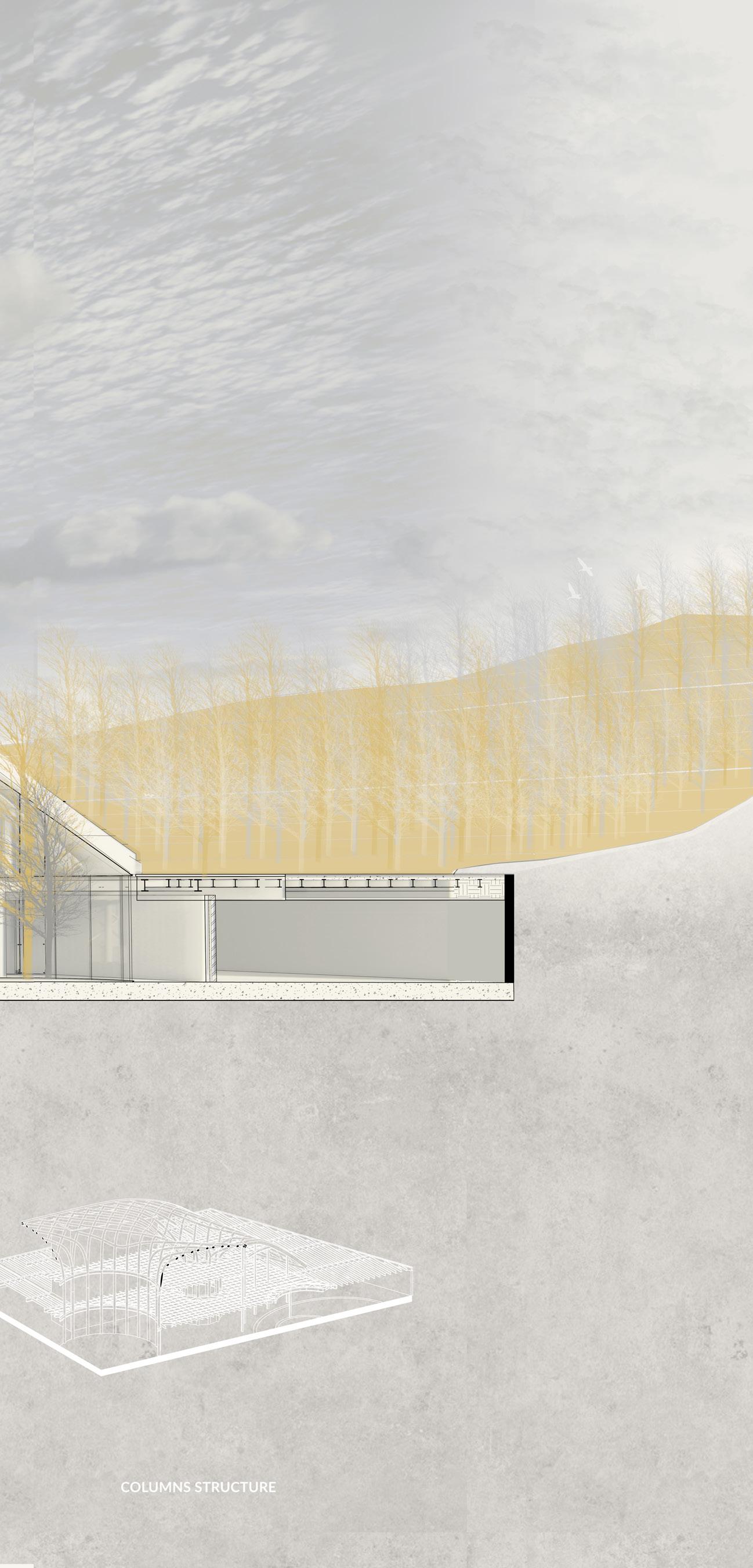
LOUVERS AS STRUCTURAL ELEMENTS
B C D
F
K L 5 5 C D E F G H I 1 2 3 0 54321 L8 3 3 A2 3 A1 3 1164 10 x 1164 mm 290 1500 160 120x200x10 rectangular steel tubes 120x200x10 rectangular steel tubes Aluminum composite panel with a wood grain pattern finish 8000 1600000 8000 8000 8000 8000 48000 8000 8000 8000 8000 W1
Air suppl y ducts
Air exhaust ducts
Hot water pipes
Cold water pipes
Cold water pipes
Discharge Stacks Drain
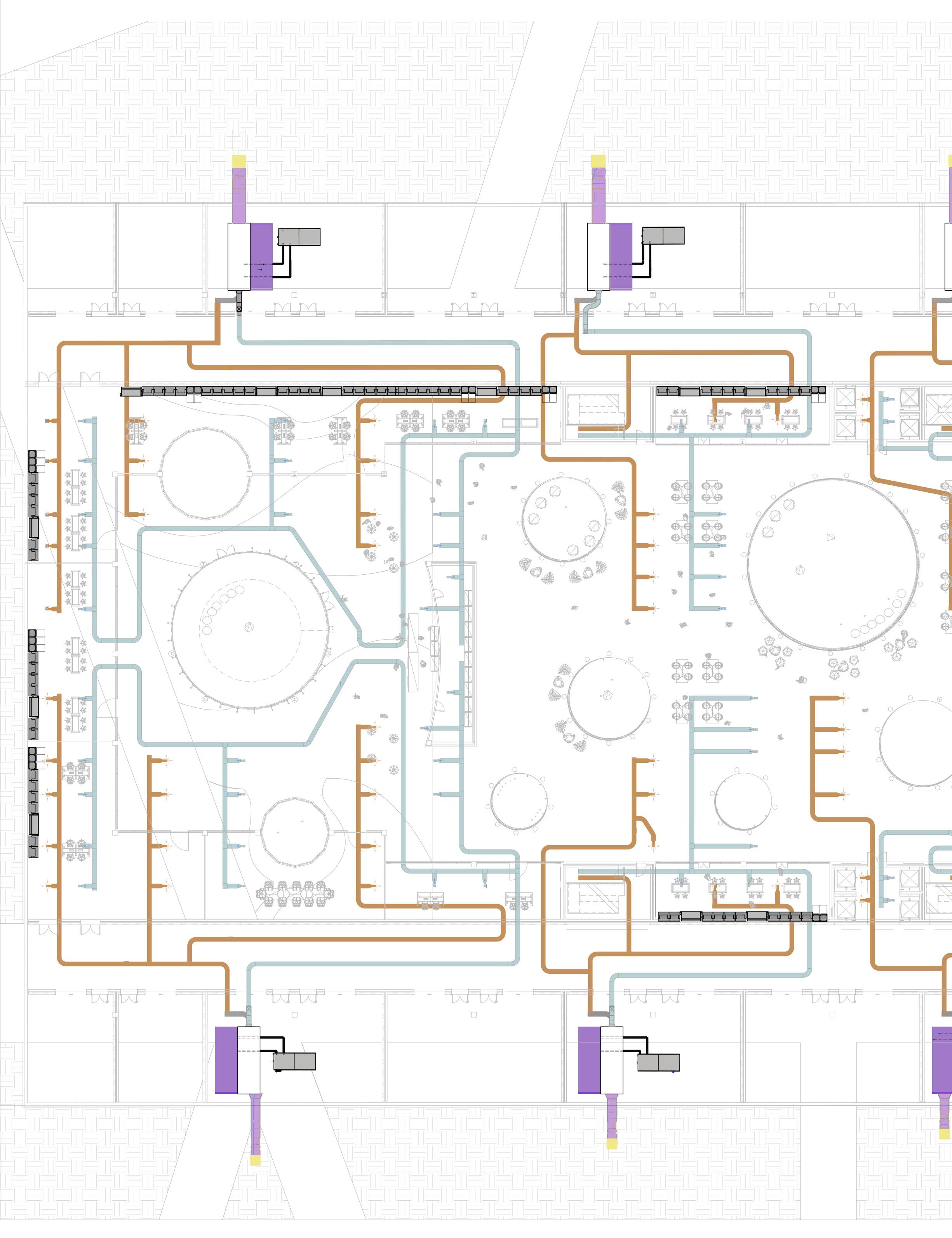
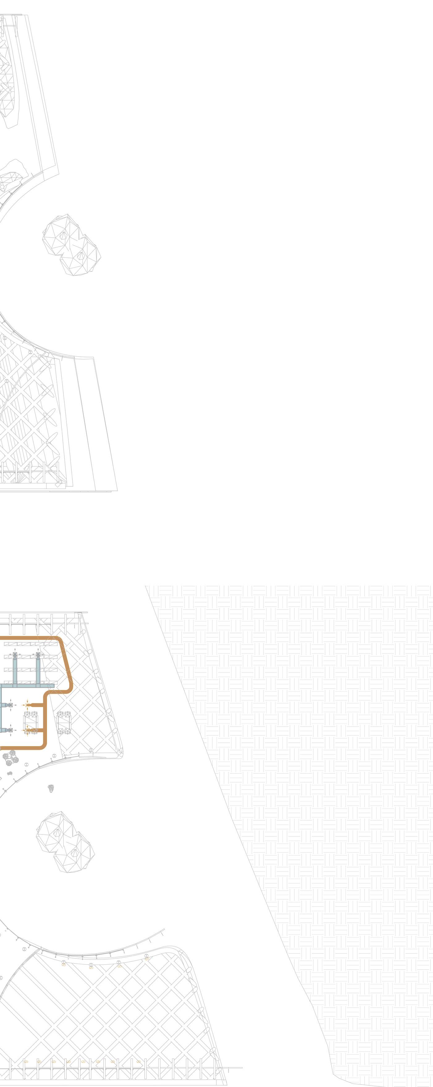
SERVICE DESIGN 141312
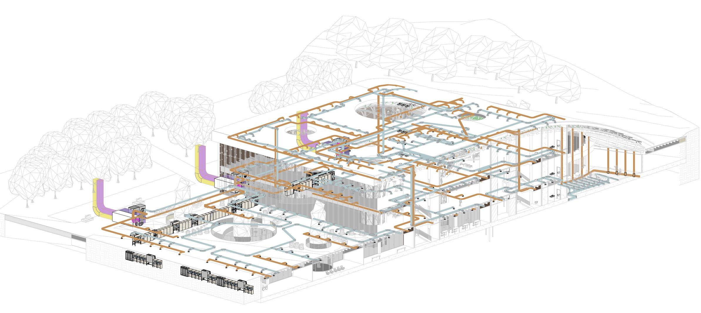

G H I 1615141312 J K 17 2 A104 1615141312 AHUHEA PUMP Air exhaust ducts maintanence zone Air Supply ducts nals Floor ai r terminals Delivery well Return well Outside air Return/ Relief air HVAC DUCT SYSTEM OVERALL VIEW HVAC DUCT SYSTEM conference hall Laboratory facilities Outside Air Retun/Releif air AHU unit Heat Pump
Delivery well Return well
Heat PumpHeat Pump
AHUAHU
Water supply room Water supply room
AHU
Water supply room Water supply room
AHU
Heat PumpHeat Pump
Delivery wellReturn well
AHU
Heat Pump
Heat Pump
HVAC SYSTEM LEGEND
Air supply ducts
Air exhaust ducts
AHU unit maintanance area
AHU unit
Outside air ducts
Return/Relief air ducts
well
AHU AHU AHU
FIRST FLOOR CEILING 1:1000
FLOOR CEILING 1:1000
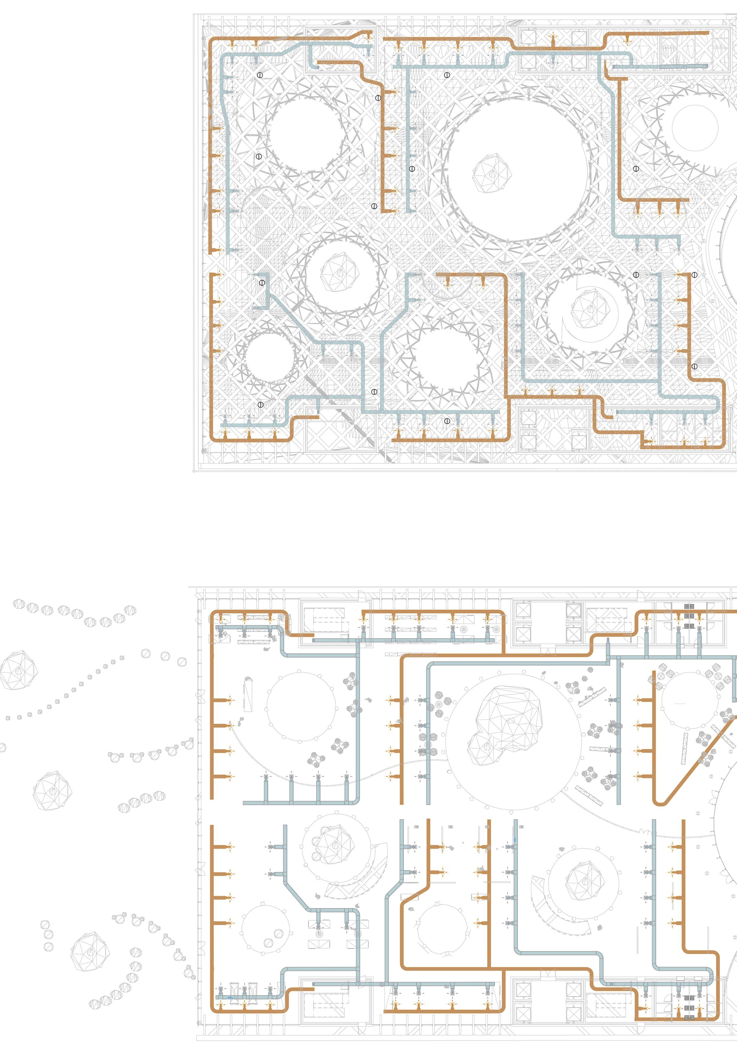
GROUND
HVAC SYSTEM LEGEND
Air supply ducts
Air exhaust ducts
AHU unit maintanance area
AHU unit
Outside air ducts
Return/Relief air ducts
Outside AirRetun/Releif air Smart totem
AHU unit
SECTION A-A’ 1:1000
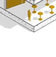
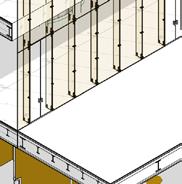
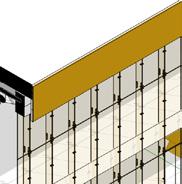
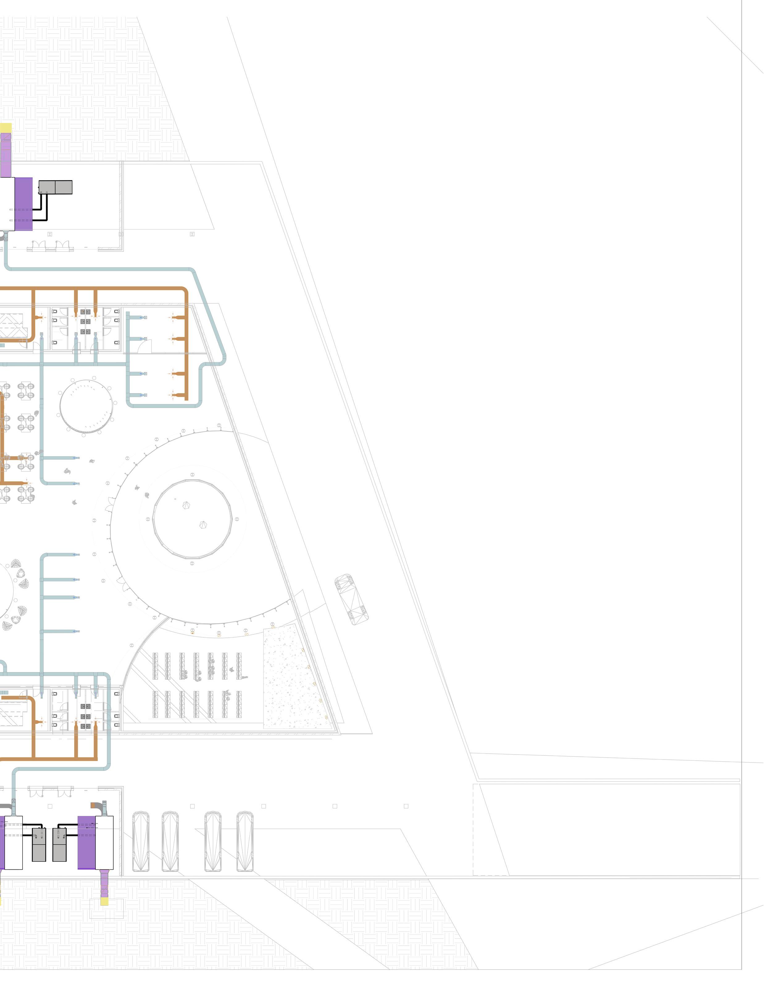
INCORPORATING AIR DUCTS IN URBAN SPACES
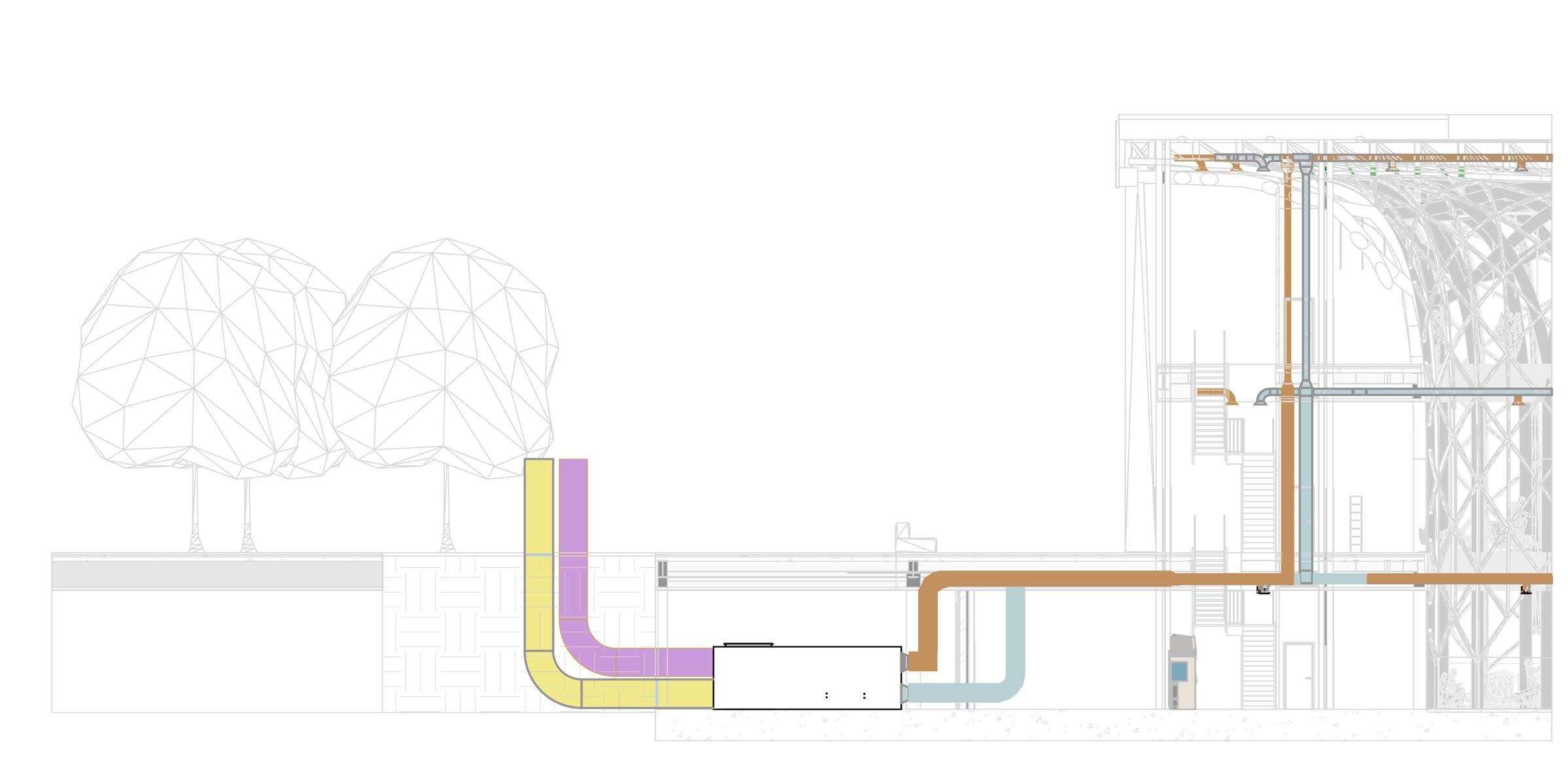
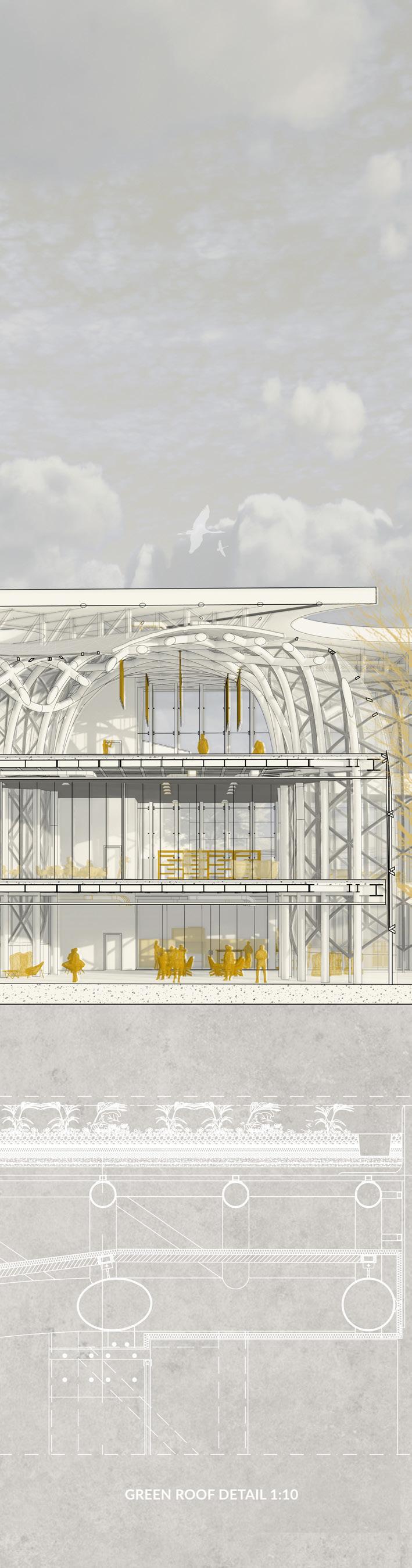
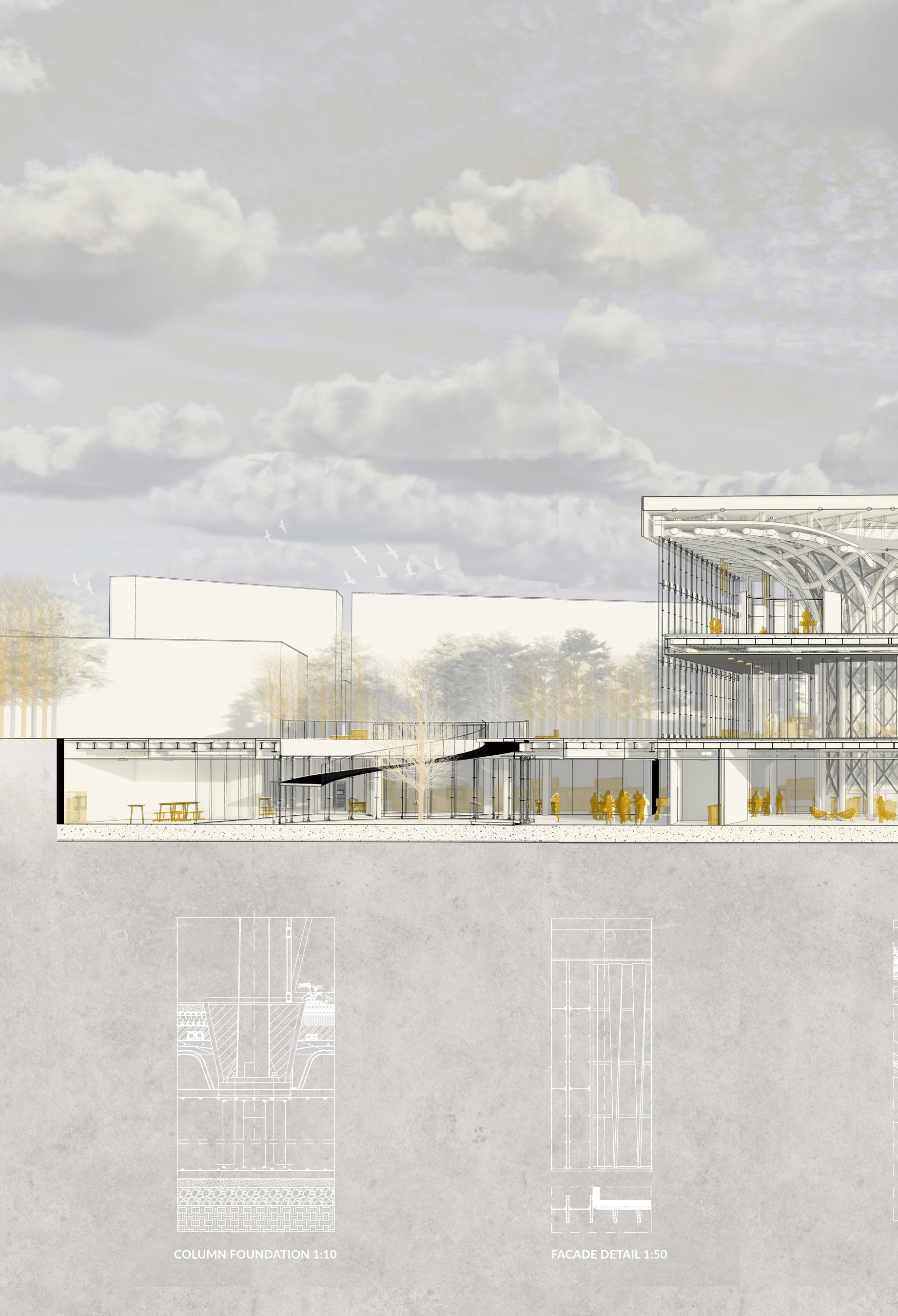
The HVAC system is completely underground, rather than on the roof, as is common in public buil dings. This was done for structu ral reasons concerning the loads on the parametric columns, in ad dition to aesthetic ones regarding the green roof being part of the green fabric. The decision, howe ver, prompted the requirement to separate/integrate the 3 m ducts rising from the underground within the context. The proposed solution is to place ‚urban totems,’ vertical components that comple ment the surrounding materials and protect the ducts from rain and wind while yet enabling air to pass through. The totems are located around the building’s pe rimeter and serve as technology hotspots throughout the park.
SMART TOTEMS
combining aesthetics and functio nality, the totems are able to pro vide services such as 5G connec tivity, digital advertising, mobility communications, web access, info point, way-finding, emergency calls, payments, urban lightning, video surveillance and charging of electronic devices.
Air supply ducts
Air exhaust ducts
AHU unit maintanance area
AHU unit
Outside air ducts
Return/Relief air ducts
SERVICE DESIGN


SMART URBAN TOTEM


ST 3000 mm 1200 mm