FOR MOTION & PERFORMANCE
LAVORAZIONE - MACHINING
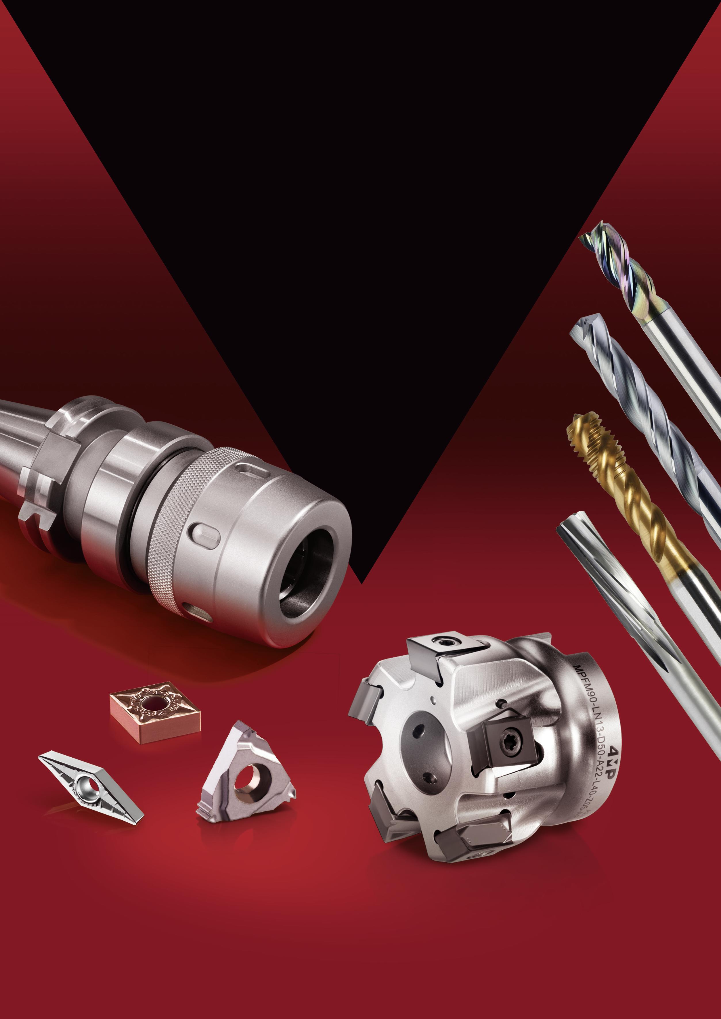
Utensili integrali, inserti, porta-inserti e accessori per macchine utensili Solid round tools, inserts, toolholders & accessories

Target QUALITY And PRODUCTIVITY
Reach INDUSTRIAL EXCELLENCE ! 4MP, the new benchmark brand in the industry sector, combines technological know-how with an emphasis on top quality. 4MP targets performance, making processes reliable and optimising costs. Placing your manufacturing tool at the cutting edge of your industry.
2
Obiettivo QUALITÀ e PRODUTTIVITÀ Per ottenere L’ECCELLENZA INDUSTRIALE!
Nuovo marchio di riferimento nel settore, 4MP combina knowhow tecnologico e requisiti di alta qualità. Punta a prestazioni, a dabilità di processo e all’ottimizzazione dei costi. Per rendere l’utensile la punta di diamante del settore industriale in cui si opera.

è un marchio distribuito in esclusiva da DEXIS, il partner europeo dell’industria.
Exclusively distributed by DEXIS, the European partner for industrial
3
professions.
Inserti e portainserti Inserts and toolholders 02 Utensili Solid round tools 01 Foratura Drilling Informazioni tecniche di foratura Drilling technical information 9 Punte in metallo duro integrali Solid carbide drills 11 Punte in acciaio HSS HSS drills 24 Fresatura Milling Informazioni tecniche di fresatura Milling technical information 48 Frese in carburo integrale Solid carbide millings 50 Frese in acciaio HSS HSS millings 58 Maschiatura Tapping Informazioni tecniche di maschiatura Tapping technical information 38 Maschi Taps 40 Tornitura Turning Informazioni tecniche tornitura Turning technical information 71 Portainserti di tornitura ISO Turning ISO toolholders 73 Inserti di tornitura ISO Turning ISO inserts 90 Filettatura Threading Informazioni tecniche filettatura Threading technical information 113 Portainserti di filettatura ISO Threading ISO toolholders 116 Inserti di filettatura Threading inserts 117 Alesatura Reaming Informazioni tecniche di alesatura Reaming technical information 62 Alesatori a macchina Machine reamers 64 Alesatori manuali Hand reamers 66 4
SOMMARIO TABLE OF CONTENTS
Tabella internazionale di conversione materiali International material conversion table 181 Accessori per macchine utensili Tooling systems 03 Bussole, pinze e accessori Sleeves, collets and accessories 205 Portautensili per fresatura - BT (JIS 6339) Milling toolholders - BT 189 Portautensili per fresatura - ISO (DIN 69871) Milling toolholders - ISO 194 Portautensili per fresatura - HSK-A (DIN 69893-1) Milling toolholders - HSK-A 199 Portautensili cilindrici e coni morse Straight shank and morse tappers toolholders 202 Scanalatura Grooving Informazioni tecniche scanalature Grooving technical information 126 Porta-inserti per scanalatura Grooving toolholders 128 Inserti per scanalatura Grooving inserts 133 Fresatura Milling Informazioni tecniche sul corpo fresa Milling technical information 142 Informazioni tecniche inserti per fresatura Milling inserts technical information 145 Corpi fresa e inserti fresa Milling cutters and inserts 152 Foratura Drilling Informazioni tecniche di foratura Drilling technical information 172 Punte a inserti Indexable drills 173 Inserti di foratura Drilling inserts 178 5
, soluzioni responsabili per UN FUTURO SOSTENIBILE
4MP, il partner delle prestazioni responsabili, è convinto che la sostenibilità sia un elemento essenziale per la longevità e il futuro delle industrie. In un’ottica globale di rispetto dell’ambiente, la gamma di strumenti per la lavorazione 4MP si impegna per preservare la qualità e la longevità dei vostri prodotti, aumentando altresì la produttività.
• RICONDIZIONAMENTO
4MP propone il ricondizionamento dei vostri utensili da taglio per ottimizzarne il ciclo di vita, limitare l’uso di materie prime e ridurre la necessità di nuovi utensili. Servizio svolto localmente per limitare l’impronta di carbonio legata al trasporto.
• RICICLO
La gamma di lavorazione 4MP sostiene il riciclo dei vostri utensili in carburo. Riciclando, partecipate alla conservazione delle risorse naturali e valorizzate il vostro contributo attraverso un vantaggio economico.
Lo sapevate? La produzione di utensili in carburo riciclato genera il 70% di risparmio energetico emettendo il 40% in meno di CO2
• RIDURRE LE EMISSIONI DI CARBONIO
Questa è una vera ambizione a lungo termine per 4MP, che si adopera per lavorare il più possibile con i produttori europei. Questa visione riflette un impegno per la sostenibilità e il desiderio di contribuire a un futuro più responsabile e rispettoso dell’ambiente.
CIRCOLARITÀ DEGLI UTENSILI DA TAGLIO
CIRCULARITY OF CUTTING TOOLS
Grazie a questi approcci sostenibili e convenienti, la gamma per le lavorazioni 4MP rientra in un approccio di economia circolare, soddisfacendo al contempo i più elevati standard di qualità e prestazioni.
Through these sustainable and cost-effective approaches, the 4MP Machining range embraces a circular economy mindset while meeting quality and performance requirements.

Preservare il nostro pianeta inizia oggi con

Machining, responsible solutions for a sustainable future
4MP Machining, the partner for responsible performance, believes that sustainability is an essential element for the longevity and future of industries. In an overall approach to environmental respect, the 4MP Machining range works to preserve the quality and longevity of your products, while improving your productivity gains.
• Reconditioning : 4MP o�ers the reconditioning of your cutting tools to optimize their lifecycle, reduce the use of raw materials, and minimize the need for new tools. Services are performed locally to reduce the carbon footprint associated with transportation.
• Recycling : The 4MP Machining range promotes the recycling of your carbide tools. By recycling, you contribute to the preservation of natural resources while realizing economic benefits.
Did you know ? Manufacturing tools from recycled carbide generates 70% energy savings and emits 40% less CO2
• Reduction of carbon emissions : Reducing carbon emissions is a long-term goal for 4MP, striving to work with European manufacturers whenever possible. This vision reflects a commitment to sustainability and a desire to contribute to a more responsible and environmentally friendly future.
Preserving our planet starts today with 4MP !
PRODUZIONE PRODUCTION USO E RIUTILIZZO USE & REUSE RACCOLTA COLLECTION DEI RIFIUTI WASTE
RICICLO RECYCLING
6
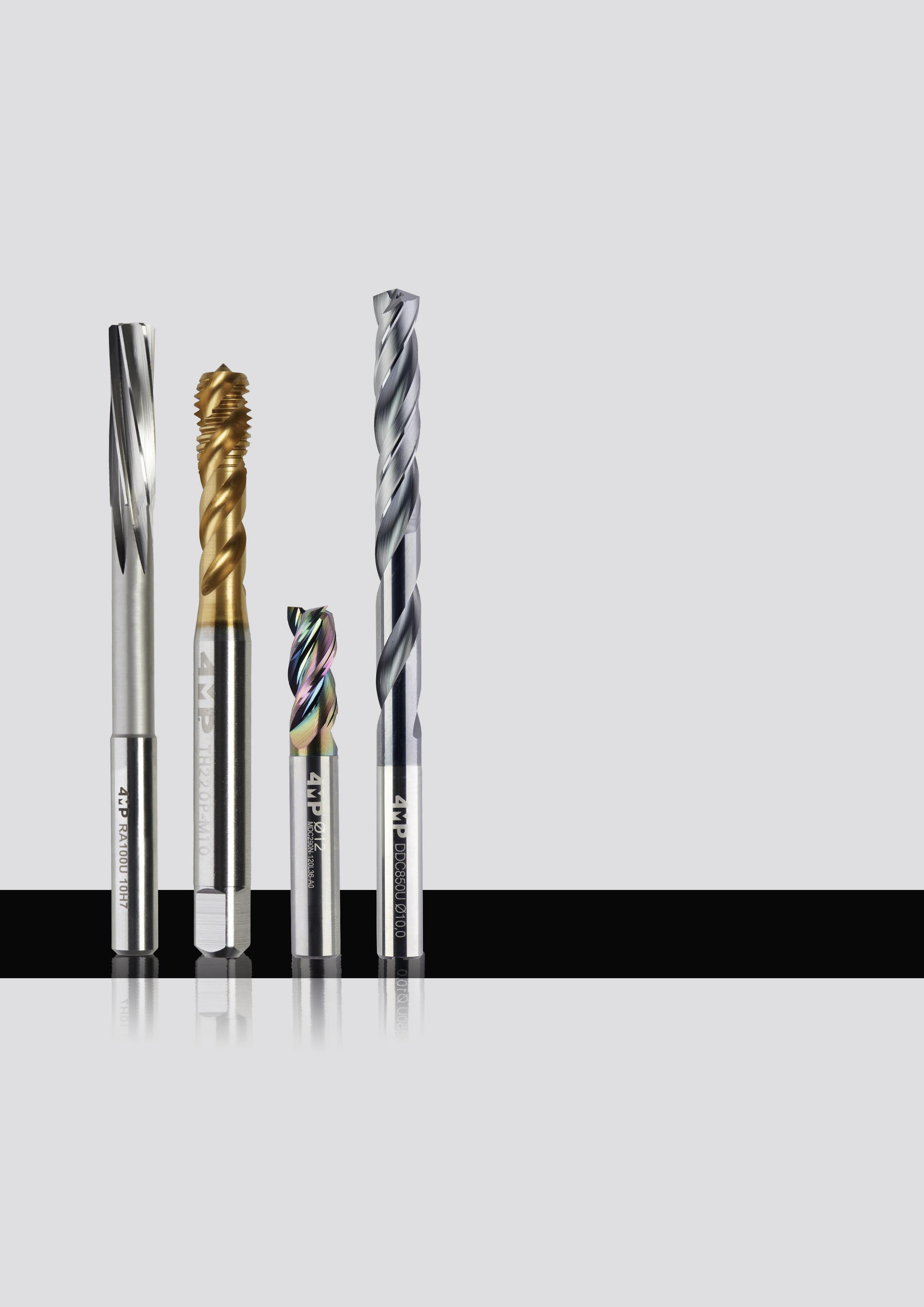
01 Utensili Solid round tools
01 Solid drilling Foratura integrale Punte in metallo duro integrale non rivestite Uncoated solid carbide drills 11 Solid milling Fresatura integrale Frese in carburo integrale Solid carbide end mills 50 Frese HSSE-PM HSSE-PM end mills 58 Frese per smussi Chamfering end mills 61 Reaming Alesatura Descrizione pittogrammi Alesatori a macchina in metallo duro integrale Solid carbide machine reamers 64 Alesatori a macchina in HSSE HSSE machine reamers 64 Alesatori manuali in HSS HSS hand reamers 66 Tapping Maschiatura Maschi passo metrico in HSS universali (M). Universal metric taps (M) 40 Maschi passo metrico in HSS-PM (M). Optimized metric taps (M) 41 Maschi passo metrico fine (MF) Universal fine metric taps (MF) 45 Maschi passo GAS (G) GAZ taps (G) 46 Maschi passo UNC UNC taps 47 Punte in metallo duro integrale rivestite Coated solid carbide drills 16 Punte in acciaio HSS HSS drills 24 Set di punte Set of drills 37
SOLID
8 Foratura integrale / Solid drilling 67
UTENSILI
ROUND TOOLS
9 030 8 A 9 1 10 D 1 0 6 D 2 C 3 3 4 U 7 4 5 -PUNTE INTEGRALI IN METALLO DURO SOLID DRILLS D: D – Punta D - Dr � ll T�po Type 1 D – Carburo D - Carb � de C – Acciaio C - Steel Mater�ale Mater�al 2 C – Carburo C - Carb � de A - HSS B - HSSE-Co5 C - HSS-Co8 D: HSSE-PM Mater�ale Mater�al 3 1 – Corta 1 - Short 2 – Lunga 2 - Length 3 - 3xD 5 - 5xD 8 - 8xD Lunghezza Length 4 030 - 3,0 mm D�ametro DC DC d�ameter 8 A – Cilindrico A - Cyl � ndr � cal W - Weldon C - Cono morse C - Morse tapper Attacco Attachment 9 1 - Interno 1 - Internal 0 - Esterno 0 - External Lubr�f�caz�one Coolant 10 0 - Non rivestito 0 - Uncoated 1 - VAP 2 - TIN 3 - ALTIN 4 - TICN 5 - TIALN 9 - SPECIALE 9 - Specıal R�vest�mento Coat�ng 5 0 - Prima generazione* 0 - F � rst generat � on Generaz�one* Generat�on 6 U - Universale U - Un � versal P – Acciaio P - Steel K – Ghisa K - Cast � ron M – Acciaio inossidabile M - Sta � nless steel S – Superlega S - H � gh temperature alloy H - Acciaio duro H - Hard steel N - Alluminio N - Alum � num C - Composito C - Compos � te Appl�caz�one Appl�cat�on 7
Foratura integrale / Solid drilling
Codifica Designation system
Gamma di punte integrali
Overview of solid drills


10
Pagina catalogo: Catalogue Page P.11 P.13 P.16 P.16 P.20 P.22 P.24 P.27 P.31 P.35 P.36 P.36 P.37 Serie Series DDC300UDDC800UDDC150UDDC350UDDC550UDDC850UDCB190UDCA810UDCB890UDCB200UDCB150UDCA100UCOFFRET / SET Materiale Material CW CW CW CW CW CW HSSE-Co5% HSS HSSE-Co5%HSSE-Co5%HSSE-Co5% HSSLunghezza punta Drill length DIN 1897 DIN338 - 3xD 5xD 8xD DIN 1897 DIN 338 Din 338 DIN 340 - -Rivestimento Coating - - TIALN TIALN TIALN TIALN GOLD - GOLD GOLD TIALN -Punte con fori per il passaggio del refrigerante CoolantGamma Ø (mm) Ø range (mm) 1 - 12 1 - 12 3 - 12 1 - 16 1 - 16 3 - 12 2 - 13 0,5 - 20 0,5 - 13 1 - 13 4 - 16 4 - 12,5Condizioni di taglio Cutting parameter Vc (m/mn)Vc (m/mn)Vc (m/mn)Vc (m/mn)Vc (m/mn)Vc (m/mn)Vc (m/mn)Vc (m/mn)Vc (m/mn)Vc (m/mn)Vc (m/mn)Vc (m/mn)Applicazioni / Applications P Acciaio non legato Non alloyed steel O 60 - 75 O 60 - 75 O 60 - 75 O 80 - 90 O 100 - 110 O 90 - 100 O 8 - 15 O 25 - 30 O 8 - 15 O 8 - 15 O 45 - 55 O 30 - 35Acciaio basso legato Low alloyed steel O 50 - 60 O 50 - 60 O 35 - 40 O 60 - 70 O 75 - 85 O 70 - 80 O 8 - 15 O 8 - 15 O 8 - 15 O 40 - 50 O 20 - 25Acciaio legato Alloyed steel O 25 - 35 O 25 - 35 O 30 - 35 O 50 - 60 O 60 - 70 O 55 - 65 O 8 - 12 O 8 - 12 O 8 - 12 O 35 - 45 O 15 - 25M Acciaio inossidabile, duplex Duplex stainless steel O 25 - 30 O 45 - 55 O 40 - 50 5 - 10 5 - 10Acciaio inossidabile autentico Autenetic stainless steel 30 - 35 30 - 35 O 40 - 50 40 - 45 O 55 - 65 O 50 - 60 O 10 - 15 5 - 10 O 10 - 15 O 10 - 15 O 15 - 20 O 6 - 10Acciaio inossidabile molto tenace e altamente legato Precipitation hardening stainless steel O 25 - 30 40 - 45 40 - 45 5 - 10 5 - 10K Ghisa grigia Grey cast iron O 60 - 70 O 60 - 70 O 60 - 70 O 65 - 75 O 80 - 90 O 80 - 90 O 25 - 30 O 30 - 40 O 15 - 20Ghisa lamellare Nodular cast iron O 80 - 90 O 80 - 90 O 60 - 70 O 90 - 100 O 100 - 110 O 100 - 110 O 30 - 35 O 30 - 40 O 15 - 20Ghisa malleabile Malleable cast iron O 60 - 70 O 60 - 70 O 60 - 70 O 65 - 75 O 100 - 110 O 100 - 110 O 30 - 35 O 30 - 40 O 15 - 20S Superlega a base di ferro Fer based alloy O 25 - 35 5 - 10Superlega a base di cobalto Co-based alloy O 25 - 35 5 - 10Superleghe a base di nichel Ni-based alloy O 25 - 35 O 10 - 15 O 10 - 15 O 10 - 15 5 - 10Lega di titanio Ti-alloy O 30 - 40 O 10 - 15 O 10 - 15 O 10 - 15 5 - 10N Alluminio < 9% Aluminium < 9% O 180 - 200 O 180 - 200 O 180 - 200 180 - 200 180 - 200 180 - 200 180 - 200 O 60 - 80 60 - 80 60 - 80 O 80 - 90 O 60 - 80Lega di alluminio Aluminum alloy O 100 - 120 O 100 - 120 O 100 - 120 180 - 200 180 - 200 180 - 200 180 - 200 O 40 - 50 60 - 80 60 - 80 O 80 - 90 O 60 - 80H Acciaio cementato, acciaio per utensili, acciaio temprato Hardened steel 30 - 40Foratura integrale / Solid drilling
Foratura , punte in metallo duro integrale
Drilling, solid carbide drills


11 01 Foratura integrale / Solid drilling
D1 D2 L2 L1 Punta metallo duro integrale serie corta DDC300U
DDC300U
Articolo Reference D1 h7 (mm) D2 h6 (mm) L1 (mm) L2 (mm) Avanzamento (mm/giro) Feed Codice Code DDC300U-010-A0-4MP 1 1 26 6 0,03 - 0,04 71 174 158 DDC300U-015-A0-4MP 1,5 1,5 32 9 0,03 - 0,04 71 174 166 DDC300U-020-A0-4MP 2 2 38 12 0,05 - 0,06 71 174 174 DDC300U-025-A0-4MP 2,5 2,5 43 14 0,05 - 0,06 71 174 182 DDC300U-030-A0-4MP 3 3 46 16 0,06 - 0,08 71 174 190 DDC300U-031-A0-4MP 3,1 3,1 49 18 0,06 - 0,08 71 174 204 DDC300U-032-A0-4MP 3,2 3,2 49 18 0,06 - 0,08 71 174 212 DDC300U-033-A0-4MP 3,3 3,3 49 18 0,06 - 0,08 71 174 220 DDC300U-034-A0-4MP 3,4 3,4 52 20 0,06 - 0,08 71 174 239 DDC300U-035-A0-4MP 3,5 3,5 52 20 0,06 - 0,08 71 174 247 DDC300U-036-A0-4MP 3,6 3,6 52 20 0,06 - 0,08 71 174 255 DDC300U-037-A0-4MP 3,7 3,7 52 20 0,06 - 0,08 71 174 263 DDC300U-038-A0-4MP 3,8 3,8 55 22 0,06 - 0,08 71 174 271 DDC300U-039-A0-4MP 3,9 3,9 55 22 0,06 - 0,08 71 174 298 DDC300U-040-A0-4MP 4 4 55 22 0,06 - 0,08 71 174 301 DDC300U-041-A0-4MP 4,1 4,1 55 22 0,06 - 0,08 71 174 328 DDC300U-042-A0-4MP 4,2 4,2 55 22 0,06 - 0,08 71 174 336 DDC300U-043-A0-4MP 4,3 4,3 58 24 0,06 - 0,08 71 174 344 DDC300U-044-A0-4MP 4,4 4,4 58 24 0,06 - 0,08 71 174 352 DDC300U-045-A0-4MP 4,5 4,5 58 24 0,06 - 0,08 71 174 360 DDC300U-046-A0-4MP 4,6 4,6 58 24 0,06 - 0,08 71 174 379 DDC300U-047-A0-4MP 4,7 4,7 58 24 0,06 - 0,08 71 174 387 DDC300U-048-A0-4MP 4,8 4,8 62 26 0,06 - 0,08 71 174 395 DDC300U-049-A0-4MP 4,9 4,9 62 26 0,06 - 0,08 71 174 409 DDC300U-050-A0-4MP 5 5 62 26 0,06 - 0,08 71 174 417 DDC300U-051-A0-4MP 5,1 5,1 62 26 0,07 - 0,09 71 174 425 DDC300U-052-A0-4MP 5,2 5,2 62 26 0,07 - 0,09 71 174 433 DDC300U-053-A0-4MP 5,3 5,3 62 26 0,07 - 0,09 71 174 441 DDC300U-054-A0-4MP 5,4 5,4 66 28 0,07 - 0,09 71 174 468 DDC300U-055-A0-4MP 5,5 5,5 66 28 0,07 - 0,09 71 174 476 DDC300U-056-A0-4MP 5,6 5,6 66 28 0,07 - 0,09 71 174 484 DDC300U-057-A0-4MP 5,7 5,7 66 28 0,07 - 0,09 71 174 492 DDC300U-058-A0-4MP 5,8 5,8 66 28 0,07 - 0,09 71 174 506 DDC300U-059-A0-4MP 5,9 5,9 66 28 0,07 - 0,09 71 174 514
Norma DIN 1897 Non rivestito, gambo cilindrico Consigliato per applicazioni generiche Solid carbide drill short
Norm DIN 1897 Uncoated, cylindrical shank Recommended for general application
Foratura, punte in metallo duro integrale
Drilling, solid carbide drills
Norma DIN 1897
Non rivestito, gambo cilindrica
Consigliato per applicazioni generiche
Solid carbide drill short DDC300U
Norm DIN 1897
Uncoated, cylindrical shank
Recommended for general application
12
Foratura integrale / Solid drilling
01
D1 D2 L2 L1 Punte in metallo duro integrale serie
corta DDC300U
Articolo Reference D1 h7 (mm) D2 h6 (mm) L1 (mm) L2 (mm) Avanzamento (mm/giro) Feed Codice Code DDC300U-060-A0-4MP 6 6 66 28 0,07 - 0,09 71 174 522 DDC300U-061-A0-4MP 6,1 6,1 70 31 0,08 - 0,12 71 174 530 DDC300U-062-A0-4MP 6,2 6,2 70 31 0,08 - 0,12 71 174 549 DDC300U-063-A0-4MP 6,3 6,3 70 31 0,08 - 0,12 71 174 557 DDC300U-064-A0-4MP 6,4 6,4 70 31 0,08 - 0,12 71 174 565 DDC300U-065-A0-4MP 6,5 6,5 70 31 0,08 - 0,12 71 174 573 DDC300U-066-A0-4MP 6,6 6,6 70 31 0,08 - 0,12 71 174 581 DDC300U-067-A0-4MP 6,7 6,7 70 31 0,08 - 0,12 71 174 603 DDC300U-068-A0-4MP 6,8 6,8 74 34 0,08 - 0,12 71 174 611 DDC300U-069-A0-4MP 6,9 6,9 74 34 0,08 - 0,12 71 174 638 DDC300U-070-A0-4MP 7 7 74 34 0,08 - 0,12 71 174 646 DDC300U-071-A0-4MP 7,1 7,1 74 34 0,08 - 0,12 71 174 654 DDC300U-072-A0-4MP 7,2 7,2 74 34 0,08 - 0,12 71 174 662 DDC300U-073-A0-4MP 7,3 7,3 74 34 0,08 - 0,12 71 174 670 DDC300U-074-A0-4MP 7,4 7,4 74 34 0,08 - 0,12 71 174 689 DDC300U-075-A0-4MP 7,5 7,5 74 34 0,08 - 0,12 71 174 697 DDC300U-076-A0-4MP 7,6 7,6 79 37 0,08 - 0,12 71 174 700 DDC300U-077-A0-4MP 7,7 7,7 79 37 0,08 - 0,12 71 174 719 DDC300U-078-A0-4MP 7,8 7,8 79 37 0,08 - 0,12 71 174 727 DDC300U-079-A0-4MP 7,9 7,9 79 37 0,08 - 0,12 71 174 735 DDC300U-080-A0-4MP 8 8 79 37 0,08 - 0,12 71 174 743 DDC300U-081-A0-4MP 8,1 8,1 79 37 0,08 - 0,12 71 174 751 DDC300U-082-A0-4MP 8,2 8,2 79 37 0,08 - 0,12 71 174 778 DDC300U-083-A0-4MP 8,3 8,3 79 37 0,08 - 0,12 71 174 786 DDC300U-084-A0-4MP 8,4 8,4 79 37 0,08 - 0,12 71 174 794 DDC300U-085-A0-4MP 8,5 8,5 79 37 0,08 - 0,12 71 174 808 DDC300U-086-A0-4MP 8,6 8,6 84 40 0,08 - 0,12 71 174 816 DDC300U-087-A0-4MP 8,7 8,7 84 40 0,08 - 0,12 71 174 824 DDC300U-088-A0-4MP 8,8 8,8 84 40 0,08 - 0,12 71 174 832 DDC300U-089-A0-4MP 8,9 8,9 84 40 0,08 - 0,12 71 174 840 DDC300U-090-A0-4MP 9 9 84 40 0,08 - 0,12 71 174 859 DDC300U-091-A0-4MP 9,1 9,1 84 40 0,11 - 0,14 71 174 867 DDC300U-092-A0-4MP 9,2 9,2 84 40 0,11 - 0,14 71 174 875 DDC300U-093-A0-4MP 9,3 9,3 84 40 0,11 - 0,14 71 174 883
Foratura, punte in metallo duro integrale
Drilling, solid carbide drills
Solid carbide drill short
Norma DIN 1897 Non rivestito, gambo cilindrico Consigliato per applicazioni generiche
Norm DIN 1897 Uncoated, cylindrical shank Recommended for general application
13 01 Foratura integrale / Solid drilling
D1 D2 L2 L1 Punta in metallo duro integrale serie corta DDC300U
DDC300U
Articolo Reference D1 h7 (mm) D2 h6 (mm) L1 (mm) L2 (mm) Avanzamento (mm/giro) Feed Codice Code DDC300U-094-A0-4MP 9,4 9,4 84 40 0,11 - 0,14 71 174 891 DDC300U-095-A0-4MP 9,5 9,5 84 40 0,11 - 0,14 71 174 905 DDC300U-096-A0-4MP 9,6 9,6 89 40 0,11 - 0,14 71 174 913 DDC300U-097-A0-4MP 9,7 9,7 89 43 0,11 - 0,14 71 174 921 DDC300U-098-A0-4MP 9,8 9,8 89 43 0,11 - 0,14 71 174 948 DDC300U-099-A0-4MP 9,9 9,9 89 43 0,11 - 0,14 71 174 956 DDC300U-100-A0-4MP 10 10 89 43 0,11 - 0,14 71 174 964 DDC300U-102-A0-4MP 10,2 10,2 89 43 0,14 - 0,17 71 174 972 DDC300U-103-A0-4MP 10,3 10,3 89 43 0,14 - 0,17 71 174 980 DDC300U-105-A0-4MP 10,5 10,5 89 43 0,14 - 0,17 71 174 999 DDC300U-110-A0-4MP 11 11 95 47 0,14 - 0,17 71 175 006 DDC300U-115-A0-4MP 11,5 11,5 95 47 0,14 - 0,17 71 175 014 DDC300U-120-A0-4MP 12 12 102 51 0,14 - 0,17 71 175 022 D1 D2 L2 L1 Punta in metallo duro integrale serie lunga DDC800U Norma DIN 338 Non rivestito, gambo cilindrico Consigliato per applicazioni generiche Solid carbide drill long DDC800U Norm DIN 338 Uncoated, cylindrical shank Recommended for general applications Articolo Reference D1 h7 (mm) D2 h6 (mm) L1 (mm) L2 (mm) Avanzamento (mm/giro) Feed Codice Code DDC800U-010-A0-4MP 1 1 34 12 0,03 - 0,04 71 175 030 DDC800U-015-A0-4MP 1,5 1,5 40 18 0,03 - 0,04 71 175 049 DDC800U-020-A0-4MP 2 2 49 24 0,05 - 0,06 71 175 057 DDC800U-025-A0-4MP 2,5 2,5 57 30 0,05 - 0,06 71 175 065 DDC800U-030-A0-4MP 3 3 61 33 0,06 - 0,08 71 175 073 DDC800U-031-A0-4MP 3,1 3,1 65 36 0,06 - 0,08 71 175 081 DDC800U-032-A0-4MP 3,2 3,2 65 36 0,06 - 0,08 71 175 103 DDC800U-033-A0-4MP 3,3 3,3 65 36 0,06 - 0,08 71 175 111 DDC800U-034-A0-4MP 3,4 3,4 70 39 0,06 - 0,08 71 175 138 DDC800U-035-A0-4MP 3,5 3,5 70 39 0,06 - 0,08 71 175 146 DDC800U-036-A0-4MP 3,6 3,6 70 39 0,06 - 0,08 71 175 154 DDC800U-037-A0-4MP 3,7 3,7 70 39 0,06 - 0,08 71 175 162 DDC800U-038-A0-4MP 3,8 3,8 75 43 0,06 - 0,08 71 175 170
14
Foratura integrale / Solid drilling
01
Foratura punte in metallo duro integrale
D1 D2 L2 L1 Punte in metallo duro integrale serie lunga DDC800U Norma DIN 338 Non rivestito, gambo cilindrico Consigliato per applicazioni generiche Solid carbide drill long DDC800U Norm DIN 338 Uncoated, cylindrical shank Recommended for general applications Articolo Reference D1 h7 (mm) D2 h6 (mm) L1 (mm) L2 (mm) Avanzamento (mm/giro) Feed Codice Code DDC800U-039-A0-4MP 3,9 3,9 75 43 0,06 - 0,08 71 175 189 DDC800U-040-A0-4MP 4 4 75 43 0,06 - 0,08 71 175 197 DDC800U-041-A0-4MP 4,1 4,1 75 43 0,06 - 0,08 71 175 200 DDC800U-042-A0-4MP 4,2 4,2 75 43 0,06 - 0,08 71 175 219 DDC800U-043-A0-4MP 4,3 4,3 80 47 0,06 - 0,08 71 175 227 DDC800U-044-A0-4MP 4,4 4,4 80 47 0,06 - 0,08 71 175 235 DDC800U-045-A0-4MP 4,5 4,5 80 47 0,06 - 0,08 71 175 243 DDC800U-046-A0-4MP 4,6 4,6 80 47 0,06 - 0,08 71 175 251 DDC800U-047-A0-4MP 4,7 4,7 80 47 0,06 - 0,08 71 175 278 DDC800U-048-A0-4MP 4,8 4,8 86 52 0,06 - 0,08 71 175 286 DDC800U-049-A0-4MP 4,9 4,9 86 52 0,06 - 0,08 71 175 294 DDC800U-050-A0-4MP 5 5 86 52 0,06 - 0,08 71 175 308 DDC800U-051-A0-4MP 5,1 5,1 86 52 0,07 - 0,09 71 175 316 DDC800U-052-A0-4MP 5,2 5,2 86 52 0,07 - 0,09 71 175 324 DDC800U-053-A0-4MP 5,3 5,3 86 52 0,07 - 0,09 71 175 332 DDC800U-054-A0-4MP 5,4 5,4 93 57 0,07 - 0,09 71 175 340 DDC800U-055-A0-4MP 5,5 5,5 93 57 0,07 - 0,09 71 175 359 DDC800U-056-A0-4MP 5,6 5,6 93 57 0,07 - 0,09 71 175 367 DDC800U-057-A0-4MP 5,7 5,7 93 57 0,07 - 0,09 71 175 375 DDC800U-058-A0-4MP 5,8 5,8 93 57 0,07 - 0,09 71 175 383 DDC800U-059-A0-4MP 5,9 5,9 93 57 0,07 - 0,09 71 175 391 DDC800U-060-A0-4MP 6 6 93 57 0,07 - 0,09 71 175 405 DDC800U-061-A0-4MP 6,1 6,1 101 63 0,08 - 0,12 71 175 413 DDC800U-062-A0-4MP 6,2 6,2 101 63 0,08 - 0,12 71 175 421 DDC800U-063-A0-4MP 6,3 6,3 101 63 0,08 - 0,12 71 175 448 DDC800U-064-A0-4MP 6,4 6,4 101 63 0,08 - 0,12 71 175 456 DDC800U-065-A0-4MP 6,5 6,5 101 63 0,08 - 0,12 71 175 464 DDC800U-066-A0-4MP 6,6 6,6 101 63 0,08 - 0,12 71 175 472 DDC800U-067-A0-4MP 6,7 6,7 101 63 0,08 - 0,12 71 175 480 DDC800U-068-A0-4MP 6,8 6,8 109 69 0,08 - 0,12 71 175 499 DDC800U-069-A0-4MP 6,9 6,9 109 69 0,08 - 0,12 71 175 502 DDC800U-070-A0-4MP 7 7 109 69 0,08 - 0,12 71 175 510 DDC800U-071-A0-4MP 7,1 7,1 109 69 0,08 - 0,12 71 175 529 DDC800U-072-A0-4MP 7,2 7,2 109 69 0,08 - 0,12 71 175 537
Drilling, solid carbide drills
Foratura punte in metallo duro integrale
Drilling, solid carbide drills
Norma DIN 338 Non rivestito, gambo cilindrico Consigliato per applicazioni generiche Solid carbide drill long
Norm DIN 338 Uncoated, cylindrical shank Recommended for general applications
15 01 Foratura integrale / Solid drilling
D1 D2 L2 L1 Punte in metallo duro integrale serie lunga
DDC800U
Articolo Reference D1 h7 (mm) D2 h6 (mm) L1 (mm) L2 (mm) Avanzamento (mm/giro) Feed Codice Code DDC800U-073-A0-4MP 7,3 7,3 109 69 0,08 - 0,12 71 175 545 DDC800U-074-A0-4MP 7,4 7,4 109 69 0,08 - 0,12 71 175 553 DDC800U-075-A0-4MP 7,5 7,5 109 69 0,08 - 0,12 71 175 561 DDC800U-076-A0-4MP 7,6 7,6 117 75 0,08 - 0,12 71 175 588 DDC800U-077-A0-4MP 7,7 7,7 117 75 0,08 - 0,12 71 175 596 DDC800U-078-A0-4MP 7,8 7,8 117 75 0,08 - 0,12 71 175 618 DDC800U-079-A0-4MP 7,9 7,9 117 75 0,08 - 0,12 71 175 626 DDC800U-080-A0-4MP 8 8 117 75 0,08 - 0,12 71 175 634 DDC800U-081-A0-4MP 8,1 8,1 117 75 0,08 - 0,12 71 175 642 DDC800U-082-A0-4MP 8,2 8,2 117 75 0,08 - 0,12 71 175 650 DDC800U-083-A0-4MP 8,3 8,3 117 75 0,08 - 0,12 71 175 669 DDC800U-084-A0-4MP 8,4 8,4 117 75 0,08 - 0,12 71 175 677 DDC800U-085-A0-4MP 8,5 8,5 117 75 0,08 - 0,12 71 175 685 DDC800U-086-A0-4MP 8,6 8,6 125 81 0,08 - 0,12 71 175 693 DDC800U-087-A0-4MP 8,7 8,7 125 81 0,08 - 0,12 71 175 707 DDC800U-088-A0-4MP 8,8 8,8 125 81 0,08 - 0,12 71 175 715 DDC800U-089-A0-4MP 8,9 8,9 125 81 0,08 - 0,12 71 175 723 DDC800U-090-A0-4MP 9 9 125 81 0,08 - 0,12 71 175 731 DDC800U-091-A0-4MP 9,1 9,1 125 81 0,11 - 0,14 71 175 758 DDC800U-092-A0-4MP 9,2 9,2 125 81 0,11 - 0,14 71 175 766 DDC800U-093-A0-4MP 9,3 9,3 125 81 0,11 - 0,14 71 175 774 DDC800U-094-A0-4MP 9,4 9,4 125 81 0,11 - 0,14 71 175 782 DDC800U-095-A0-4MP 9,5 9,5 125 81 0,11 - 0,14 71 175 790 DDC800U-096-A0-4MP 9,6 9,6 133 87 0,11 - 0,14 71 175 804 DDC800U-097-A0-4MP 9,7 9,7 133 87 0,11 - 0,14 71 175 812 DDC800U-098-A0-4MP 9,8 9,8 133 87 0,11 - 0,14 71 175 820 DDC800U-099-A0-4MP 9,9 9,9 133 87 0,11 - 0,14 71 175 839 DDC800U-100-A0-4MP 10 10 133 87 0,11 - 0,14 71 175 847 DDC800U-102-A0-4MP 10,2 10,2 133 87 0,14 - 0,17 71 175 855 DDC800U-105-A0-4MP 10,5 10,5 133 87 0,14 - 0,17 71 175 863 DDC800U-110-A0-4MP 11 11 142 94 0,14 - 0,17 71 175 871 DDC800U-115-A0-4MP 11,5 11,5 142 94 0,14 - 0,17 71 175 898 DDC800U-120-A0-4MP 12 12 151 101 0,14 - 0,17 71 175 901
DDC800U
Foratura punte in metallo duro integrale
Drilling, solid carbide drills

16
Foratura integrale / Solid drilling
01
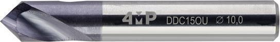
D1 D2 L2 L1 Frese per smussi e a centrare in metallo duro integrale a 90° DDC150U Gambo cilindrico
TIALN Solid carbide spotting drill 90° DDC150U Cylindrical shank TIALN coating Articolo Reference D1 (mm) D2 h6 (mm) L1 (mm) L2 (mm) Avanzamento (mm/giro) Feed Codice Code DDC150U-030-A0-4MP 3 3 38 8 0,01 - 0,06 71 184 196 DDC150U-040-A0-4MP 4 4 50 10 0,02 - 0,08 71 184 218 DDC150U-060-A0-4MP 6 6 57 13 0,07 - 0,14 71 184 226 DDC150U-080-A0-4MP 8 8 63 19 0,07 - 0,16 71 184 234 DDC150U-100-A1-4MP 10 10 66 20 0,07 - 0,16 71 184 242 DDC150U-120-A1-4MP 12 12 73 22 0,07 - 0,16 71 184 250 D1 D2 L2 L1 Punta in metallo duro integrale 3xD DDC350U Senza passaggio refrigerante Gambo cilindrico rinforzato Per applicazioni generiche Solid carbide drill 3xD DDC350U Without internal coolant Cylindrical shank For general application Articolo Reference D1 m7 (mm) D2 h6 (mm) L1 (mm) L2 (mm) Avanzamento (mm/giro) Feed Codice Code DDC350U-010-A0-4MP 1 3 38 8 0,02 - 0,05 71 175 928 DDC350U-015-A0-4MP 1,5 3 50 8 0,02 - 0,05 71 175 936 DDC350U-020-A0-4MP 2 3 50 16 0,02 - 0,05 71 175 944 DDC350U-025-A0-4MP 2,5 3 50 20 0,06 - 0,14 71 175 952 DDC350U-030-A0-4MP 3 6 62 20 0,06 - 0,14 71 175 960 DDC350U-031-A0-4MP 3,1 6 62 20 0,06 - 0,14 71 175 979 DDC350U-032-A0-4MP 3,2 6 62 20 0,06 - 0,14 71 175 987 DDC350U-033-A0-4MP 3,3 6 62 20 0,06 - 0,14 71 175 995 DDC350U-034-A0-4MP 3,4 6 62 20 0,06 - 0,14 71 176 002 DDC350U-035-A0-4MP 3,5 6 62 20 0,06 - 0,14 71 176 010 DDC350U-036-A0-4MP 3,6 6 62 20 0,06 - 0,14 71 176 029 DDC350U-037-A0-4MP 3,7 6 62 20 0,06 - 0,14 71 176 037 DDC350U-038-A0-4MP 3,8 6 66 24 0,06 - 0,14 71 176 045 DDC350U-039-A0-4MP 3,9 6 66 24 0,06 - 0,14 71 176 053 DDC350U-040-A0-4MP 4 6 66 24 0,07 - 0,17 71 176 061 DDC350U-041-A0-4MP 4,1 6 66 24 0,07 - 0,17 71 176 088 DDC350U-042-A0-4MP 4,2 6 66 24 0,07 - 0,17 71 176 096 DDC350U-043-A0-4MP 4,3 6 66 24 0,07 - 0,17 71 176 118 DDC350U-044-A0-4MP 4,4 6 66 24 0,07 - 0,17 71 176 126 DDC350U-045-A0-4MP 4,5 6 66 24 0,07 - 0,17 71 176 134
Rivestimento
Foratura punte in metallo duro integrale
Drilling, solid carbide drills
Senza passaggio refrigerante
Gambo cilindrico rinforzato
Per applicazioni generiche
17 01 Foratura integrale / Solid drilling
D1 D2 L2 L1 Punta in metallo duro integrale 3xD DDC350U
Solid carbide drill 3xD DDC350U Without internal coolant Cylindrical shank For general
Articolo Reference D1 m7 (mm) D2 h6 (mm) L1 (mm) L2 (mm) Avanzamento (mm/giro) Feed Codice Code DDC350U-046-A0-4MP 4,6 6 66 24 0,07 - 0,17 71 176 142 DDC350U-047-A0-4MP 4,7 6 66 24 0,07 - 0,17 71 176 150 DDC350U-048-A0-4MP 4,8 6 66 28 0,07 - 0,17 71 176 169 DDC350U-049-A0-4MP 4,9 6 66 28 0,07 - 0,17 71 176 177 DDC350U-050-A0-4MP 5 6 66 28 0,07 - 0,17 71 176 185 DDC350U-051-A0-4MP 5,1 6 66 28 0,09 - 0,20 71 176 193 DDC350U-052-A0-4MP 5,2 6 66 28 0,09 - 0,20 71 176 207 DDC350U-053-A0-4MP 5,3 6 66 28 0,09 - 0,20 71 176 215 DDC350U-054-A0-4MP 5,4 6 66 28 0,09 - 0,20 71 176 223 DDC350U-055-A0-4MP 5,5 6 66 28 0,09 - 0,20 71 176 231 DDC350U-056-A0-4MP 5,6 6 66 28 0,09 - 0,20 71 176 258 DDC350U-057-A0-4MP 5,7 6 66 28 0,09 - 0,20 71 176 266 DDC350U-058-A0-4MP 5,8 6 66 28 0,09 - 0,20 71 176 274 DDC350U-059-A0-4MP 5,9 6 66 28 0,09 - 0,20 71 176 282 DDC350U-060-A0-4MP 6 6 66 28 0,09 - 0,20 71 176 290 DDC350U-061-A0-4MP 6,1 8 79 34 0,10 - 0,24 71 176 304 DDC350U-062-A0-4MP 6,2 8 79 34 0,10 - 0,24 71 176 312 DDC350U-063-A0-4MP 6,3 8 79 34 0,10 - 0,24 71 176 320 DDC350U-064-A0-4MP 6,4 8 79 34 0,10 - 0,24 71 176 339 DDC350U-065-A0-4MP 6,5 8 79 34 0,10 - 0,24 71 176 347 DDC350U-066-A0-4MP 6,6 8 79 34 0,10 - 0,24 71 176 355 DDC350U-067-A0-4MP 6,7 8 79 34 0,10 - 0,24 71 176 363 DDC350U-068-A0-4MP 6,8 8 79 34 0,10 - 0,24 71 176 371 DDC350U-069-A0-4MP 6,9 8 79 34 0,10 - 0,24 71 176 398 DDC350U-070-A0-4MP 7 8 79 34 0,10 - 0,24 71 176 401 DDC350U-071-A0-4MP 7,1 8 79 41 0,10 - 0,24 71 176 428 DDC350U-072-A0-4MP 7,2 8 79 41 0,10 - 0,24 71 176 436 DDC350U-073-A0-4MP 7,3 8 79 41 0,10 - 0,24 71 176 444 DDC350U-074-A0-4MP 7,4 8 79 41 0,10 - 0,24 71 176 452 DDC350U-075-A0-4MP 7,5 8 79 41 0,10 - 0,24 71 176 460 DDC350U-076-A0-4MP 7,6 8 79 41 0,10 - 0,24 71 176 479 DDC350U-077-A0-4MP 7,7 8 79 41 0,10 - 0,24 71 176 487 DDC350U-078-A0-4MP 7,8 8 79 41 0,10 - 0,24 71 176 495 DDC350U-079-A0-4MP 7,9 8 79 41 0,10 - 0,24 71 176 509 DDC350U-080-A0-4MP 8 8 79 41 0,10 - 0,24 71 176 517 DDC350U-081-A0-4MP 8,1 10 89 47 0,12 - 0,28 71 176 525
application
Foratura punte in metallo duro integrale
Drilling, solid carbide drills
Senza passaggio refrigerante
Gambo cilindrico rinforzato
Per applicazioni generiche
18
Foratura integrale / Solid drilling
01
D1 D2 L2 L1 Punta in metallo duro integrale 3xD DDC350U
Solid carbide drill 3xD DDC350U Without internal coolant Cylindrical
For general
Articolo Reference D1 m7 (mm) D2 h6 (mm) L1 (mm) L2 (mm) Avanzamento (mm/giro) Feed Codice Code DDC350U-082-A0-4MP 8,2 10 89 47 0,12 - 0,28 71 176 533 DDC350U-083-A0-4MP 8,3 10 89 47 0,12 - 0,28 71 176 541 DDC350U-084-A0-4MP 8,4 10 89 47 0,12 - 0,28 71 176 568 DDC350U-085-A0-4MP 8,5 10 89 47 0,12 - 0,28 71 176 576 DDC350U-086-A0-4MP 8,6 10 89 47 0,12 - 0,28 71 176 584 DDC350U-087-A0-4MP 8,7 10 89 47 0,12 - 0,28 71 176 592 DDC350U-088-A0-4MP 8,8 10 89 47 0,12 - 0,28 71 176 606 DDC350U-089-A0-4MP 8,9 10 89 47 0,12 - 0,28 71 176 614 DDC350U-090-A0-4MP 9 10 89 47 0,12 - 0,28 71 176 622 DDC350U-091-A0-4MP 9,1 10 89 47 0,12 - 0,28 71 176 630 DDC350U-092-A0-4MP 9,2 10 89 47 0,12 - 0,28 71 176 649 DDC350U-093-A0-4MP 9,3 10 89 47 0,12 - 0,28 71 176 657 DDC350U-094-A0-4MP 9,4 10 89 47 0,12 - 0,28 71 176 665 DDC350U-095-A0-4MP 9,5 10 89 47 0,12 - 0,28 71 176 673 DDC350U-096-A0-4MP 9,6 10 89 47 0,12 - 0,28 71 176 681 DDC350U-097-A0-4MP 9,7 10 89 47 0,12 - 0,28 71 176 703 DDC350U-098-A0-4MP 9,8 10 89 47 0,12 - 0,28 71 176 711 DDC350U-099-A0-4MP 9,9 10 89 47 0,12 - 0,28 71 176 738 DDC350U-100-A0-4MP 10 10 89 47 0,15 - 0,35 71 176 746 DDC350U-101-A0-4MP 10,1 12 102 55 0,15 - 0,35 71 176 754 DDC350U-102-A0-4MP 10,2 12 102 55 0,15 - 0,35 71 176 762 DDC350U-103-A0-4MP 10,3 12 102 55 0,15 - 0,35 71 176 770 DDC350U-104-A0-4MP 10,4 12 102 55 0,15 - 0,35 71 176 789 DDC350U-105-A0-4MP 10,5 12 102 55 0,15 - 0,35 71 176 797 DDC350U-110-A0-4MP 11 12 102 55 0,15 - 0,35 71 176 800 DDC350U-115-A0-4MP 11,5 12 102 55 0,15 - 0,35 71 176 819 DDC350U-120-A0-4MP 12 12 102 55 0,15 - 0,35 71 176 827 DDC350U-125-A0-4MP 12,5 14 107 60 0,15 - 0,35 71 176 835 DDC350U-130-A0-4MP 13 14 107 60 0,18 - 0,43 71 176 843 DDC350U-135-A0-4MP 13,5 14 107 60 0,18 - 0,43 71 176 851 DDC350U-140-A0-4MP 14 14 107 60 0,18 - 0,43 71 176 878 DDC350U-145-A0-4MP 14,5 16 115 65 0,20 - 0,45 71 176 886 DDC350U-150-A0-4MP 15 16 115 65 0,20 - 0,45 71 176 894 DDC350U-160-A0-4MP 16 16 115 65 0,20 - 0,45 71 176 908
shank
application
Foratura punte in metallo duro integrale
Drilling, solid carbide drills

Senza passaggio refrigerante
Gambo cilindrico rinforzato
Per applicazioni generiche
19 01 Foratura integrale / Solid drilling
D1 D2 L2 L1 Punta in metallo duro integrale 3xD DDC350U
drill 5xD DDC550U With internal
Cylindrical
For
Articolo Reference D1 (mm) D2 (mm) L1 (mm) L2 (mm) Avanzamento (mm/giro) Feed Codice Code DDC550U-010-A1-4MP 1 4 55 10 0,017 - 0,03 71 176 916 DDC550U-015-A1-4MP 1,5 4 55 12 0,025 - 0,045 71 176 924 DDC550U-020-A1-4MP 2 4 57 21 0,033 - 0,06 71 176 932 DDC550U-025-A1-4MP 2,5 4 57 21 0,05 - 0,09 71 176 940 DDC550U-030-A1-4MP 3 6 66 28 0,05 - 0,09 71 176 959 DDC550U-031-A1-4MP 3,1 6 66 28 0,05 - 0,09 71 176 967 DDC550U-032-A1-4MP 3,2 6 66 28 0,05 - 0,09 71 176 975 DDC550U-033-A1-4MP 3,3 6 66 28 0,05 - 0,09 71 176 983 DDC550U-034-A1-4MP 3,4 6 66 28 0,05 - 0,09 71 176 991 DDC550U-035-A1-4MP 3,5 6 66 28 0,08 - 0,16 71 177 009 DDC550U-036-A1-4MP 3,6 6 66 28 0,08 - 0,16 71 177 017 DDC550U-037-A1-4MP 3,7 6 66 28 0,08 - 0,16 71 177 025 DDC550U-038-A1-4MP 3,8 6 74 36 0,08 - 0,16 71 177 033 DDC550U-039-A1-4MP 3,9 6 74 36 0,08 - 0,16 71 177 041 DDC550U-040-A1-4MP 4 6 74 36 0,08 - 0,16 71 177 068 DDC550U-041-A1-4MP 4,1 6 74 36 0,08 - 0,16 71 177 076 DDC550U-042-A1-4MP 4,2 6 74 36 0,08 - 0,16 71 177 084 DDC550U-043-A1-4MP 4,3 6 74 36 0,08 - 0,16 71 177 092 DDC550U-044-A1-4MP 4,4 6 74 36 0,08 - 0,16 71 177 106 DDC550U-045-A1-4MP 4,5 6 74 36 0,08 - 0,16 71 177 114 DDC550U-046-A1-4MP 4,6 6 74 36 0,08 - 0,16 71 177 122 DDC550U-047-A1-4MP 4,7 6 74 36 0,08 - 0,16 71 177 130 DDC550U-048-A1-4MP 4,8 6 82 44 0,08 - 0,16 71 177 149 DDC550U-049-A1-4MP 4,9 6 82 44 0,08 - 0,16 71 177 157 DDC550U-050-A1-4MP 5 6 82 44 0,08 - 0,16 71 177 165 DDC550U-051-A1-4MP 5,1 6 82 44 0,08 - 0,16 71 177 173 DDC550U-052-A1-4MP 5,2 6 82 44 0,08 - 0,16 71 177 181 DDC550U-053-A1-4MP 5,3 6 82 44 0,08 - 0,16 71 177 203 DDC550U-054-A1-4MP 5,4 6 82 44 0,08 - 0,16 71 177 211 DDC550U-055-A1-4MP 5,5 6 82 44 0,12 - 0,22 71 177 238 DDC550U-056-A1-4MP 5,6 6 82 44 0,12 - 0,22 71 177 246 DDC550U-057-A1-4MP 5,7 6 82 44 0,12 - 0,22 71 177 254 DDC550U-058-A1-4MP 5,8 6 82 44 0,12 - 0,22 71 177 262 DDC550U-059-A1-4MP 5,9 6 82 44 0,12 - 0,22 71 177 270
Solid carbide
coolant
shank
general application
Foratura punte in metallo duro integrale
Drilling, solid carbide drills
Con passaggio di refrigerante
Gambo cilindrico rinforzato
Per applicazioni generiche
20
Foratura integrale / Solid drilling
01
D1 D2 L2 L1 Punta in metallo duro integrale 5xD DDC550U
Solid carbide drill 5xD DDC550U With internal
Cylindrical
Articolo Reference D1 (mm) D2 (mm) L1 (mm) L2 (mm) Avanzamento (mm/giro) Feed Codice Code DDC550U-060-A1-4MP 6 6 82 44 0,12 - 0,22 71 177 289 DDC550U-061-A1-4MP 6,1 8 91 53 0,12 - 0,22 71 177 297 DDC550U-062-A1-4MP 6,2 8 91 53 0,12 - 0,22 71 177 300 DDC550U-063-A1-4MP 6,3 8 91 53 0,12 - 0,22 71 177 319 DDC550U-064-A1-4MP 6,4 8 91 53 0,12 - 0,22 71 177 327 DDC550U-065-A1-4MP 6,5 8 91 53 0,12 - 0,22 71 177 335 DDC550U-066-A1-4MP 6,6 8 91 53 0,12 - 0,22 71 177 343 DDC550U-067-A1-4MP 6,7 8 91 53 0,12 - 0,22 71 177 351 DDC550U-068-A1-4MP 6,8 8 91 53 0,12 - 0,22 71 177 378 DDC550U-069-A1-4MP 6,9 8 91 53 0,12 - 0,22 71 177 386 DDC550U-070-A1-4MP 7 8 91 53 0,12 - 0,22 71 177 394 DDC550U-071-A1-4MP 7,1 8 91 53 0,12 - 0,22 71 177 408 DDC550U-072-A1-4MP 7,2 8 91 53 0,12 - 0,22 71 177 416 DDC550U-073-A1-4MP 7,3 8 91 53 0,12 - 0,22 71 177 424 DDC550U-074-A1-4MP 7,4 8 91 53 0,12 - 0,22 71 177 432 DDC550U-075-A1-4MP 7,5 8 91 53 0,12 - 0,22 71 177 440 DDC550U-076-A1-4MP 7,6 8 91 53 0,12 - 0,22 71 177 459 DDC550U-077-A1-4MP 7,7 8 91 53 0,12 - 0,22 71 177 467 DDC550U-078-A1-4MP 7,8 8 91 53 0,12 - 0,22 71 177 475 DDC550U-079-A1-4MP 7,9 8 91 53 0,12 - 0,22 71 177 483 DDC550U-080-A1-4MP 8 8 91 53 0,12 - 0,22 71 177 491 DDC550U-081-A1-4MP 8,1 10 103 61 0,12 - 0,22 71 177 505 DDC550U-082-A1-4MP 8,2 10 103 61 0,12 - 0,22 71 177 513 DDC550U-083-A1-4MP 8,3 10 103 61 0,12 - 0,22 71 177 521 DDC550U-084-A1-4MP 8,4 10 103 61 0,12 - 0,22 71 177 548 DDC550U-085-A1-4MP 8,5 10 103 61 0,15 - 0,28 71 177 556 DDC550U-086-A1-4MP 8,6 10 103 61 0,15 - 0,28 71 177 564 DDC550U-087-A1-4MP 8,7 10 103 61 0,15 - 0,28 71 177 572 DDC550U-088-A1-4MP 8,8 10 103 61 0,15 - 0,28 71 177 580 DDC550U-089-A1-4MP 8,9 10 103 61 0,15 - 0,28 71 177 599 DDC550U-090-A1-4MP 9 10 103 61 0,15 - 0,28 71 177 602 DDC550U-091-A1-4MP 9,1 10 103 61 0,15 - 0,28 71 177 610 DDC550U-092-A1-4MP 9,2 10 103 61 0,15 - 0,28 71 177 629 DDC550U-093-A1-4MP 9,3 10 103 61 0,15 - 0,28 71 177 637
coolant
shank For general application
Foratura punte in metallo duro integrale
Drilling, solid carbide drills
21 01 Foratura integrale / Solid drilling
D1 D2 L2 L1 Punta in metallo duro integrale 5xD DDC550U
passaggio
carbide drill 5xD DDC550U With internal coolant Cylindrical shank For general application Articolo Reference D1 (mm) D2 (mm) L1 (mm) L2 (mm) Avanzamento (mm/giro) Feed Codice Code DDC550U-094-A1-4MP 9,4 10 103 61 0,15 - 0,28 71 177 645 DDC550U-095-A1-4MP 9,5 10 103 61 0,15 - 0,28 71 177 653 DDC550U-096-A1-4MP 9,6 10 103 61 0,15 - 0,28 71 177 661 DDC550U-097-A1-4MP 9,7 10 103 61 0,15 - 0,28 71 177 688 DDC550U-098-A1-4MP 9,8 10 103 61 0,15 - 0,28 71 177 696 DDC550U-099-A1-4MP 9,9 10 103 61 0,15 - 0,28 71 177 718 DDC550U-100-A1-4MP 10 10 103 61 0,15 - 0,28 71 177 726 DDC550U-101-A1-4MP 10,1 12 118 71 0,15 - 0,28 71 177 734 DDC550U-102-A1-4MP 10,2 12 118 71 0,15 - 0,28 71 177 742 DDC550U-103-A1-4MP 10,3 12 118 71 0,15 - 0,28 71 177 750 DDC550U-104-A1-4MP 10,4 12 118 71 0,15 - 0,28 71 177 769 DDC550U-105-A1-4MP 10,5 12 118 71 0,15 - 0,28 71 177 777 DDC550U-110-A1-4MP 11 12 118 71 0,15 - 0,28 71 177 785 DDC550U-115-A1-4MP 11,5 12 118 71 0,15 - 0,28 71 177 793 DDC550U-120-A1-4MP 12 12 118 71 0,15 - 0,28 71 177 807 DDC550U-125-A1-4MP 12,5 14 124 77 0,20 - 0,34 71 177 815 DDC550U-130-A1-4MP 13 14 124 77 0,20 - 0,34 71 177 823 DDC550U-135-A1-4MP 13,5 14 124 77 0,20 - 0,34 71 177 831 DDC550U-140-A1-4MP 14 14 124 77 0,20 - 0,34 71 177 858 DDC550U-145-A1-4MP 14,5 16 133 83 0,20 - 0,34 71 177 866 DDC550U-150-A1-4MP 15 16 133 83 0,20 - 0,34 71 177 874 DDC550U-160-A1-4MP 16 16 133 83 0,20 - 0,34 71 177 882
Con
di refrigerante Gambo cilindrico rinforzato Doppio listello Solid


Con passaggio di refrigerante
Gambo cilindrico rinforzato
Doppio listello
Per applicazioni generiche
22
Foratura integrale / Solid drilling
D1 D2 L2 L1 Punta in metallo duro integrale 8xD DDC850U
01
Foratura punte in metallo duro integrale Drilling, solid carbide drills
Solid carbide drill 8xD DDC850U With internal coolant
Articolo Reference D1 (mm) D2 (mm) L1 (mm) L2 (mm) Avanzamento (mm/giro) Feed Codice Code DDC850U-030-A1-4MP 3 6 72 34 0,05 - 0,09 71 177 890 DDC850U-031-A1-4MP 3,1 6 72 34 0,05 - 0,09 71 177 904 DDC850U-032-A1-4MP 3,2 6 72 34 0,05 - 0,09 71 177 912 DDC850U-033-A1-4MP 3,3 6 72 34 0,05 - 0,09 71 177 920 DDC850U-034-A1-4MP 3,4 6 72 34 0,05 - 0,09 71 177 939 DDC850U-035-A1-4MP 3,5 6 72 34 0,07 - 0,14 71 177 947 DDC850U-036-A1-4MP 3,6 6 72 34 0,07 - 0,14 71 177 955 DDC850U-037-A1-4MP 3,7 6 72 34 0,07 - 0,14 71 177 963 DDC850U-038-A1-4MP 3,8 6 81 43 0,07 - 0,14 71 177 971 DDC850U-039-A1-4MP 3,9 6 81 43 0,07 - 0,14 71 177 998 DDC850U-040-A1-4MP 4 6 81 43 0,07 - 0,14 71 178 005 DDC850U-041-A1-4MP 4,1 6 81 43 0,07 - 0,14 71 178 013 DDC850U-042-A1-4MP 4,2 6 81 43 0,07 - 0,14 71 178 021 DDC850U-043-A1-4MP 4,3 6 81 43 0,07 - 0,14 71 178 048 DDC850U-044-A1-4MP 4,4 6 81 43 0,07 - 0,14 71 178 056 DDC850U-045-A1-4MP 4,5 6 81 43 0,08 - 0,17 71 178 064 DDC850U-046-A1-4MP 4,6 6 81 43 0,08 - 0,17 71 178 072 DDC850U-047-A1-4MP 4,7 6 95 57 0,08 - 0,17 71 178 080 DDC850U-048-A1-4MP 4,8 6 95 57 0,08 - 0,17 71 178 099 DDC850U-049-A1-4MP 4,9 6 95 57 0,08 - 0,17 71 178 102 DDC850U-050-A1-4MP 5 6 95 57 0,08 - 0,17 71 178 110 DDC850U-051-A1-4MP 5,1 6 95 57 0,08 - 0,17 71 178 129 DDC850U-052-A1-4MP 5,2 6 95 57 0,08 - 0,17 71 178 137 DDC850U-053-A1-4MP 5,3 6 95 57 0,08 - 0,17 71 178 145 DDC850U-054-A1-4MP 5,4 6 95 57 0,08 - 0,17 71 178 153 DDC850U-055-A1-4MP 5,5 6 95 57 0,08 - 0,17 71 178 161 DDC850U-056-A1-4MP 5,6 6 95 57 0,10 - 0,17 71 178 188 DDC850U-057-A1-4MP 5,7 6 95 57 0,10 - 0,17 71 178 196 DDC850U-058-A1-4MP 5,8 6 95 57 0,10 - 0,17 71 178 218 DDC850U-059-A1-4MP 5,9 6 95 57 0,10 - 0,17 71 178 226 DDC850U-060-A1-4MP 6 6 95 57 0,10 - 0,17 71 178 234 DDC850U-061-A1-4MP 6,1 8 114 76 0,10 - 0,17 71 178 242 DDC850U-062-A1-4MP 6,2 8 114 76 0,10 - 0,17 71 178 250 DDC850U-063-A1-4MP 6,3 8 114 76 0,10 - 0,17 71 178 269 DDC850U-064-A1-4MP 6,4 8 114 76 0,10 - 0,17 71 178 277 DDC850U-065-A1-4MP 6,5 8 114 76 0,10 - 0,17 71 178 285
Cylindrical shank For general application
Foratura punte in metallo duro integrale
Drilling, solid carbide drills
Con passaggio di refrigerante
Gambo cilindrico rinforzato
Doppio listello
Per applicazioni generiche
23 01 Foratura integrale / Solid drilling
D1 D2 L2 L1 Punta in metallo duro integrale 8xD DDC850U
Solid carbide drill 8xD DDC850U With internal coolant Cylindrical
For general
Articolo Reference D1 (mm) D2 (mm) L1 (mm) L2 (mm) Avanzamento (mm/giro) Feed Codice Code DDC850U-066-A1-4MP 6,6 8 114 76 0,12 - 0,20 71 178 293 DDC850U-067-A1-4MP 6,7 8 114 76 0,12 - 0,20 71 178 307 DDC850U-068-A1-4MP 6,8 8 114 76 0,12 - 0,20 71 178 315 DDC850U-069-A1-4MP 6,9 8 114 76 0,12 - 0,20 71 178 323 DDC850U-070-A1-4MP 7 8 114 76 0,12 - 0,20 71 178 331 DDC850U-071-A1-4MP 7,1 8 114 76 0,12 - 0,20 71 178 358 DDC850U-072-A1-4MP 7,2 8 114 76 0,12 - 0,20 71 178 366 DDC850U-073-A1-4MP 7,3 8 114 76 0,12 - 0,20 71 178 374 DDC850U-074-A1-4MP 7,4 8 114 76 0,12 - 0,20 71 178 382 DDC850U-075-A1-4MP 7,5 8 114 76 0,12 - 0,20 71 178 390 DDC850U-076-A1-4MP 7,6 8 114 76 0,12 - 0,20 71 178 404 DDC850U-077-A1-4MP 7,7 8 114 76 0,12 - 0,20 71 178 412 DDC850U-078-A1-4MP 7,8 8 114 76 0,12 - 0,20 71 178 420 DDC850U-079-A1-4MP 7,9 8 114 76 0,12 - 0,20 71 178 439 DDC850U-080-A1-4MP 8 8 114 76 0,12 - 0,20 71 178 447 DDC850U-081-A1-4MP 8,1 10 142 95 0,13 - 0,27 71 178 455 DDC850U-082-A1-4MP 8,2 10 142 95 0,13 - 0,27 71 178 463 DDC850U-083-A1-4MP 8,3 10 142 95 0,13 - 0,27 71 178 471 DDC850U-084-A1-4MP 8,4 10 142 95 0,13 - 0,27 71 178 498 DDC850U-085-A1-4MP 8,5 10 142 95 0,13 - 0,27 71 178 501 DDC850U-086-A1-4MP 8,6 10 142 95 0,13 - 0,27 71 178 528 DDC850U-087-A1-4MP 8,7 10 142 95 0,13 - 0,27 71 178 536 DDC850U-088-A1-4MP 8,8 10 142 95 0,13 - 0,27 71 178 544 DDC850U-089-A1-4MP 8,9 10 142 95 0,13 - 0,27 71 178 552 DDC850U-090-A1-4MP 9 10 142 95 0,13 - 0,27 71 178 560 DDC850U-091-A1-4MP 9,1 10 142 95 0,13 - 0,27 71 178 579 DDC850U-092-A1-4MP 9,2 10 142 95 0,13 - 0,27 71 178 587 DDC850U-093-A1-4MP 9,3 10 142 95 0,13 - 0,27 71 178 595 DDC850U-094-A1-4MP 9,4 10 142 95 0,13 - 0,27 71 178 609 DDC850U-095-A1-4MP 9,5 10 142 95 0,13 - 0,27 71 178 617 DDC850U-096-A1-4MP 9,6 10 142 95 0,13 - 0,27 71 178 625 DDC850U-097-A1-4MP 9,7 10 142 95 0,13 - 0,27 71 178 633 DDC850U-098-A1-4MP 9,8 10 142 95 0,13 - 0,27 71 178 641 DDC850U-099-A1-4MP 9,9 10 142 95 0,13 - 0,27 71 178 668 DDC850U-100-A1-4MP 10 10 142 95 0,13 - 0,27 71 178 676 DDC850U-120-A1-4MP 12 12 162 114 0,15 - 0,28 71 178 684
shank
application
Norma DIN 1897
Finitura ORO Per applicazioni generiche
24 01 Foratura integrale / Solid drilling
drills D1 D2 L2 L1 Punta HSS-E serie corta DCB190U HSSE-Co5% A lata
Foratura, punte in acciaio HSS Drilling, HSS
HSS-E short drill DCB190U HSSE-Co5% Norm DIN 1897 GOLD finish For general application Articolo Reference D1 h8 (mm) D2 (mm) L1 (mm) L2 (mm) Avanzamento (mm/giro) Feed Codice Code DCB190U-0200-A0-4MP 2 2 38 12 0,02 - 0,03 71 178 757 DCB190U-0210-A0-4MP 2,1 2,1 38 12 0,02 - 0,03 71 178 765 DCB190U-0220-A0-4MP 2,2 2,2 40 13 0,02 - 0,03 71 178 773 DCB190U-0230-A0-4MP 2,3 2,3 40 13 0,02 - 0,03 71 178 781 DCB190U-0240-A0-4MP 2,4 2,4 43 14 0,02 - 0,03 71 178 803 DCB190U-0250-A0-4MP 2,5 2,5 43 14 0,02 - 0,03 71 178 811 DCB190U-0260-A0-4MP 2,6 2,6 43 14 0,02 - 0,03 71 178 838 DCB190U-0270-A0-4MP 2,7 2,7 46 16 0,02 - 0,03 71 178 846 DCB190U-0280-A0-4MP 2,8 2,8 46 16 0,02 - 0,03 71 178 854 DCB190U-0290-A0-4MP 2,9 2,9 46 16 0,02 - 0,03 71 178 862 DCB190U-0300-A0-4MP 3 3 46 16 0,03 - 0,04 71 178 870 DCB190U-0310-A0-4MP 3,1 3,1 49 18 0,03 - 0,04 71 178 889 DCB190U-0320-A0-4MP 3,2 3,2 49 18 0,03 - 0,04 71 178 897 DCB190U-0330-A0-4MP 3,3 3,3 49 18 0,03 - 0,04 71 178 900 DCB190U-0340-A0-4MP 3,4 3,4 52 20 0,03 - 0,04 71 178 919 DCB190U-0350-A0-4MP 3,5 3,5 52 20 0,03 - 0,04 71 178 927 DCB190U-0360-A0-4MP 3,6 3,6 52 20 0,03 - 0,04 71 178 935 DCB190U-0370-A0-4MP 3,7 3,7 52 20 0,03 - 0,04 71 178 943 DCB190U-0380-A0-4MP 3,8 3,8 55 22 0,03 - 0,04 71 178 951 DCB190U-0390-A0-4MP 3,9 3,9 55 22 0,03 - 0,04 71 178 978 DCB190U-0400-A0-4MP 4 4 55 22 0,04 - 0,05 71 178 986 DCB190U-0410-A0-4MP 4,1 4,1 55 22 0,04 - 0,05 71 178 994 DCB190U-0420-A0-4MP 4,2 4,2 55 22 0,04 - 0,05 71 179 001 DCB190U-0430-A0-4MP 4,3 4,3 58 24 0,04 - 0,05 71 179 028 DCB190U-0440-A0-4MP 4,4 4,4 58 24 0,04 - 0,05 71 179 036 DCB190U-0450-A0-4MP 4,5 4,5 58 24 0,04 - 0,05 71 179 044 DCB190U-0460-A0-4MP 4,6 4,6 58 24 0,04 - 0,05 71 179 052 DCB190U-0470-A0-4MP 4,7 4,7 58 24 0,04 - 0,05 71 179 060 DCB190U-0480-A0-4MP 4,8 4,8 62 26 0,04 - 0,05 71 179 079 DCB190U-0490-A0-4MP 4,9 4,9 62 26 0,04 - 0,05 71 179 087 DCB190U-0500-A0-4MP 5 5 62 26 0,05 - 0,06 71 179 095 DCB190U-0510-A0-4MP 5,1 5,1 62 26 0,05 - 0,06 71 179 109 DCB190U-0520-A0-4MP 5,2 5,2 62 26 0,05 - 0,06 71 179 117 DCB190U-0530-A0-4MP 5,3 5,3 62 26 0,05 - 0,06 71 179 125
Foratura, punte in acciaio HSS
Drilling, HSS drills
Norma DIN 1897
Finitura ORO
Per applicazioni generiche
25 01 Foratura integrale / Solid drilling
D1 D2 L2 L1 Punta HSS-E serie corta DCB190U HSSE-Co5% A lata
HSS-E short drill DCB190U HSSE-Co5% Norm DIN 1897 GOLD finish For general application Articolo Reference D1 h8 (mm) D2 (mm) L1 (mm) L2 (mm) Avanzamento (mm/giro) Feed Codice Code DCB190U-0540-A0-4MP 5,4 5,4 66 28 0,05 - 0,06 71 179 133 DCB190U-0550-A0-4MP 5,5 5,5 66 28 0,05 - 0,06 71 179 141 DCB190U-0560-A0-4MP 5,6 5,6 66 28 0,05 - 0,06 71 179 168 DCB190U-0570-A0-4MP 5,7 5,7 66 28 0,05 - 0,06 71 179 176 DCB190U-0580-A0-4MP 5,8 5,8 66 28 0,05 - 0,06 71 179 184 DCB190U-0590-A0-4MP 5,9 5,9 66 28 0,05 - 0,06 71 179 192 DCB190U-0600-A0-4MP 6 6 66 28 0,06 - 0,07 71 179 206 DCB190U-0610-A0-4MP 6,1 6,1 70 31 0,06 - 0,07 71 179 214 DCB190U-0620-A0-4MP 6,2 6,2 70 31 0,06 - 0,07 71 179 222 DCB190U-0630-A0-4MP 6,3 6,3 70 31 0,06 - 0,07 71 179 230 DCB190U-0640-A0-4MP 6,4 6,4 70 31 0,06 - 0,07 71 179 249 DCB190U-0650-A0-4MP 6,5 6,5 70 31 0,06 - 0,07 71 179 257 DCB190U-0660-A0-4MP 6,6 6,6 70 31 0,06 - 0,07 71 179 265 DCB190U-0670-A0-4MP 6,7 6,7 70 31 0,06 - 0,07 71 179 273 DCB190U-0680-A0-4MP 6,8 6,8 74 34 0,06 - 0,07 71 179 281 DCB190U-0690-A0-4MP 6,9 6,9 74 34 0,06 - 0,07 71 179 303 DCB190U-0700-A0-4MP 7 7 74 34 0,06 - 0,07 71 179 311 DCB190U-0730-A0-4MP 7,3 7,3 74 34 0,06 - 0,07 71 179 338 DCB190U-0740-A0-4MP 7,4 7,4 74 34 0,06 - 0,07 71 179 346 DCB190U-0750-A0-4MP 7,5 7,5 74 34 0,06 - 0,07 71 179 354 DCB190U-0770-A0-4MP 7,7 7,7 79 37 0,06 - 0,07 71 179 362 DCB190U-0780-A0-4MP 7,8 7,8 79 37 0,06 - 0,07 71 179 370 DCB190U-0790-A0-4MP 7,9 7,9 79 37 0,06 - 0,07 71 179 389 DCB190U-0800-A0-4MP 8 8 79 37 0,07 - 0,09 71 179 397 DCB190U-0810-A0-4MP 8,1 8,1 79 37 0,07 - 0,09 71 179 400 DCB190U-0820-A0-4MP 8,2 8,2 79 37 0,07 - 0,09 71 179 419 DCB190U-0830-A0-4MP 8,3 8,3 79 37 0,07 - 0,09 71 179 427 DCB190U-0840-A0-4MP 8,4 8,4 79 37 0,07 - 0,09 71 179 435 DCB190U-0850-A0-4MP 8,5 8,5 79 37 0,07 - 0,09 71 179 443 DCB190U-0860-A0-4MP 8,6 8,6 84 40 0,07 - 0,09 71 179 451 DCB190U-0870-A0-4MP 8,7 8,7 84 40 0,07 - 0,09 71 179 478 DCB190U-0880-A0-4MP 8,8 8,8 84 40 0,07 - 0,09 71 179 486 DCB190U-0890-A0-4MP 8,9 8,9 84 40 0,07 - 0,09 71 179 494 DCB190U-0900-A0-4MP 9 9 84 40 0,07 - 0,09 71 179 508
Norma DIN 1897
Finitura ORO Per applicazioni generiche
26
Foratura integrale / Solid drilling
D1 D2 L2 L1 Punta HSS-E serie corta DCB190U HSSE-Co5% A lata
01
Foratura, punte in acciaio HSS Drilling, HSS drills
HSS-E short drill DCB190U HSSE-Co5% Norm DIN 1897 GOLD finish For general application Articolo Reference D1 h8 (mm) D2 (mm) L1 (mm) L2 (mm) Avanzamento (mm/giro) Feed Codice Code DCB190U-0930-A0-4MP 9,3 9,3 84 40 0,07 - 0,09 71 179 516 DCB190U-0950-A0-4MP 9,5 9,5 84 40 0,07 - 0,09 71 179 524 DCB190U-1000-A0-4MP 10 10 89 43 0,08 - 0,10 71 179 532 DCB190U-1020-A0-4MP 10,2 10,2 89 43 0,08 - 0,10 71 179 540 DCB190U-1030-A0-4MP 10,3 10,3 89 43 0,08 - 0,10 71 179 559 DCB190U-1050-A0-4MP 10,5 10,5 89 43 0,08 - 0,10 71 179 567 DCB190U-1100-A0-4MP 11 11 95 47 0,08 - 0,10 71 179 575 DCB190U-1150-A0-4MP 11,5 11,5 95 47 0,08 - 0,10 71 179 583 DCB190U-1200-A0-4MP 12 12 102 51 0,10 - 0,12 71 179 591 DCB190U-1300-A0-4MP 13 13 105 51 0,10 - 0,12 71 179 605
27 01 Foratura integrale / Solid drilling
HSS drills D1 D2 L2 L1 Punta HSS standard DCA810U HSS A lata Norma DIN 338 Finitura NERA Per applicazioni generiche HSS standard drill DCA810U HSS Norm DIN 338 BLACK finish For general application Articolo Reference D1 h8 (mm) D2 (mm) L1 (mm) L2 (mm) Avanzamento (mm/giro) Feed Codice Code DCA810U-0050-A0-4MP 0,5 0,5 22 6 0,03 - 0,05 71 179 613 DCA810U-0060-A0-4MP 0,6 0,6 24 7 0,03 - 0,05 71 179 621 DCA810U-0070-A0-4MP 0,7 0,7 28 9 0,03 - 0,05 71 179 648 DCA810U-0080-A0-4MP 0,8 0,8 30 10 0,03 - 0,05 71 179 656 DCA810U-0090-A0-4MP 0,9 0,9 32 11 0,03 - 0,05 71 179 664 DCA810U-0100-A0-4MP 1 1 34 12 0,03 - 0,05 71 179 672 DCA810U-0110-A0-4MP 1,1 1,1 36 14 0,03 - 0,05 71 179 680 DCA810U-0120-A0-4MP 1,2 1,2 38 16 0,03 - 0,05 71 179 699 DCA810U-0130-A0-4MP 1,3 1,3 38 16 0,03 - 0,05 71 179 702 DCA810U-0140-A0-4MP 1,4 1,4 40 18 0,03 - 0,05 71 179 710 DCA810U-0150-A0-4MP 1,5 1,5 40 18 0,03 - 0,05 71 179 729 DCA810U-0160-A0-4MP 1,6 1,6 43 20 0,03 - 0,05 71 179 737 DCA810U-0170-A0-4MP 1,7 1,7 43 20 0,03 - 0,05 71 179 745 DCA810U-0180-A0-4MP 1,8 1,8 46 22 0,03 - 0,05 71 179 753 DCA810U-0190-A0-4MP 1,9 1,9 46 22 0,03 - 0,05 71 179 761 DCA810U-0200-A0-4MP 2 2 49 24 0,045 - 0,08 71 179 788 DCA810U-0210-A0-4MP 2,1 2,1 49 24 0,045 - 0,08 71 179 796 DCA810U-0220-A0-4MP 2,2 2,2 53 27 0,045 - 0,08 71 179 818 DCA810U-0230-A0-4MP 2,3 2,3 53 27 0,045 - 0,08 71 179 826 DCA810U-0240-A0-4MP 2,4 2,4 57 30 0,045 - 0,08 71 179 834 DCA810U-0250-A0-4MP 2,5 2,5 57 30 0,045 - 0,08 71 179 842 DCA810U-0260-A0-4MP 2,6 2,6 57 30 0,045 - 0,08 71 179 850 DCA810U-0270-A0-4MP 2,7 2,7 61 33 0,045 - 0,08 71 179 869 DCA810U-0280-A0-4MP 2,8 2,8 61 33 0,045 - 0,08 71 179 877 DCA810U-0290-A0-4MP 2,9 2,9 61 33 0,045 - 0,08 71 179 885 DCA810U-0300-A0-4MP 3 3 61 33 0,055 - 0,11 71 179 893 DCA810U-0310-A0-4MP 3,1 3,1 65 36 0,055 - 0,11 71 179 907 DCA810U-0320-A0-4MP 3,2 3,2 65 36 0,055 - 0,11 71 179 915 DCA810U-0330-A0-4MP 3,3 3,3 65 36 0,055 - 0,11 71 179 923 DCA810U-0340-A0-4MP 3,4 3,4 70 39 0,055 - 0,11 71 179 931 DCA810U-0350-A0-4MP 3,5 3,5 70 39 0,055 - 0,11 71 179 958 DCA810U-0360-A0-4MP 3,6 3,6 70 39 0,055 - 0,11 71 179 966 DCA810U-0370-A0-4MP 3,7 3,7 70 39 0,055 - 0,11 71 179 974 DCA810U-0380-A0-4MP 3,8 3,8 75 43 0,055 - 0,11 71 179 982 DCA810U-0390-A0-4MP 3,9 3,9 75 43 0,055 - 0,11 71 179 990 DCA810U-0400-A0-4MP 4 4 75 43 0,07 - 0,13 71 180 018
Foratura, punte in acciaio HSS Drilling,
28 01 Foratura integrale / Solid drilling
punte in acciaio HSS Drilling, HSS drills D1 D2 L2 L1 Punta HSS standard DCA810U HSS A lata Norma DIN 338 Finitura NERA Per applicazioni generiche HSS standard drill DCA810U HSS Norm DIN 338 BLACK finish For general application Articolo Reference D1 h8 (mm) D2 (mm) L1 (mm) L2 (mm) Avanzamento (mm/giro) Feed Codice Code DCA810U-0410-A0-4MP 4,1 4,1 75 43 0,07 - 0,13 71 180 026 DCA810U-0420-A0-4MP 4,2 4,2 75 43 0,07 - 0,13 71 180 034 DCA810U-0430-A0-4MP 4,3 4,3 80 47 0,07 - 0,13 71 180 042 DCA810U-0440-A0-4MP 4,4 4,4 80 47 0,07 - 0,13 71 180 050 DCA810U-0450-A0-4MP 4,5 4,5 80 47 0,07 - 0,13 71 180 069 DCA810U-0460-A0-4MP 4,6 4,6 80 47 0,07 - 0,13 71 180 077 DCA810U-0470-A0-4MP 4,7 4,7 80 47 0,07 - 0,13 71 180 085 DCA810U-0480-A0-4MP 4,8 4,8 86 52 0,07 - 0,13 71 180 093 DCA810U-0490-A0-4MP 4,9 4,9 86 52 0,07 - 0,13 71 180 107 DCA810U-0500-A0-4MP 5 5 86 52 0,08 - 0,15 71 180 115 DCA810U-0510-A0-4MP 5,1 5,1 86 52 0,08 - 0,15 71 180 123 DCA810U-0520-A0-4MP 5,2 5,2 86 52 0,08 - 0,15 71 180 131 DCA810U-0530-A0-4MP 5,3 5,3 86 52 0,08 - 0,15 71 180 158 DCA810U-0540-A0-4MP 5,4 5,4 93 57 0,08 - 0,15 71 180 166 DCA810U-0550-A0-4MP 5,5 5,5 93 57 0,08 - 0,15 71 180 174 DCA810U-0560-A0-4MP 5,6 5,6 93 57 0,08 - 0,15 71 180 182 DCA810U-0570-A0-4MP 5,7 5,7 93 57 0,08 - 0,15 71 180 190 DCA810U-0580-A0-4MP 5,8 5,8 93 57 0,08 - 0,15 71 180 204 DCA810U-0590-A0-4MP 5,9 5,9 93 57 0,08 - 0,15 71 180 212 DCA810U-0600-A0-4MP 6 6 93 57 0,10 - 0,19 71 180 220 DCA810U-0610-A0-4MP 6,1 6,1 101 63 0,10 - 0,19 71 180 239 DCA810U-0620-A0-4MP 6,2 6,2 101 63 0,10 - 0,19 71 180 247 DCA810U-0630-A0-4MP 6,3 6,3 101 63 0,10 - 0,19 71 180 255 DCA810U-0640-A0-4MP 6,4 6,4 101 63 0,10 - 0,19 71 180 263 DCA810U-0650-A0-4MP 6,5 6,5 101 63 0,10 - 0,19 71 180 271 DCA810U-0660-A0-4MP 6,6 6,6 101 63 0,10 - 0,19 71 180 298 DCA810U-0670-A0-4MP 6,7 6,7 101 63 0,10 - 0,19 71 180 301 DCA810U-0680-A0-4MP 6,8 6,8 109 69 0,10 - 0,19 71 180 328 DCA810U-0690-A0-4MP 6,9 6,9 109 69 0,10 - 0,19 71 180 336 DCA810U-0700-A0-4MP 7 7 109 69 0,10 - 0,19 71 180 344 DCA810U-0710-A0-4MP 7,1 7,1 109 69 0,10 - 0,19 71 180 352 DCA810U-0720-A0-4MP 7,2 7,2 109 69 0,10 - 0,19 71 180 360 DCA810U-0730-A0-4MP 7,3 7,3 109 69 0,10 - 0,19 71 180 379 DCA810U-0740-A0-4MP 7,4 7,4 109 69 0,10 - 0,19 71 180 387 DCA810U-0750-A0-4MP 7,5 7,5 109 69 0,10 - 0,19 71 180 395 DCA810U-0760-A0-4MP 7,6 7,6 117 75 0,10 - 0,19 71 180 409
Foratura,
29 01 Foratura integrale / Solid drilling
HSS drills D1 D2 L2 L1 Punta HSS standard DCA810U HSS A lata Norma DIN 338 Finitura NERA Per applicazioni generiche HSS standard drill DCA810U HSS Norm DIN 338 BLACK finish For general application Articolo Reference D1 h8 (mm) D2 (mm) L1 (mm) L2 (mm) Avanzamento (mm/giro) Feed Codice Code DCA810U-0770-A0-4MP 7,7 7,7 117 75 0,10 - 0,19 71 180 417 DCA810U-0780-A0-4MP 7,8 7,8 117 75 0,10 - 0,19 71 180 425 DCA810U-0790-A0-4MP 7,9 7,9 117 75 0,10 - 0,19 71 180 433 DCA810U-0800-A0-4MP 8 8 117 75 0,12 - 0,22 71 180 441 DCA810U-0810-A0-4MP 8,1 8,1 117 75 0,12 - 0,22 71 180 468 DCA810U-0820-A0-4MP 8,2 8,2 117 75 0,12 - 0,22 71 180 476 DCA810U-0830-A0-4MP 8,3 8,3 117 75 0,12 - 0,22 71 180 484 DCA810U-0840-A0-4MP 8,4 8,4 117 75 0,12 - 0,22 71 180 492 DCA810U-0850-A0-4MP 8,5 8,5 117 75 0,12 - 0,22 71 180 506 DCA810U-0860-A0-4MP 8,6 8,6 125 81 0,12 - 0,22 71 180 514 DCA810U-0870-A0-4MP 8,7 8,7 125 81 0,12 - 0,22 71 180 522 DCA810U-0880-A0-4MP 8,8 8,8 125 81 0,12 - 0,22 71 180 530 DCA810U-0890-A0-4MP 8,9 8,9 125 81 0,12 - 0,22 71 180 549 DCA810U-0900-A0-4MP 9 9 125 81 0,12 - 0,22 71 180 557 DCA810U-0910-A0-4MP 9,1 9,1 125 81 0,12 - 0,22 71 180 565 DCA810U-0920-A0-4MP 9,2 9,2 125 81 0,12 - 0,22 71 180 573 DCA810U-0930-A0-4MP 9,3 9,3 125 81 0,12 - 0,22 71 180 581 DCA810U-0940-A0-4MP 9,4 9,4 125 81 0,12 - 0,22 71 180 603 DCA810U-0950-A0-4MP 9,5 9,5 125 81 0,12 - 0,22 71 180 611 DCA810U-0960-A0-4MP 9,6 9,6 133 87 0,12 - 0,22 71 180 638 DCA810U-0970-A0-4MP 9,7 9,7 133 87 0,12 - 0,22 71 180 646 DCA810U-0980-A0-4MP 9,8 9,8 133 87 0,12 - 0,22 71 180 654 DCA810U-0990-A0-4MP 9,9 9,9 133 87 0,12 - 0,22 71 180 662 DCA810U-1000-A0-4MP 10 10 133 87 0,15 - 0,26 71 180 670 DCA810U-1010-A0-4MP 10,1 10,1 133 87 0,15 - 0,26 71 180 689 DCA810U-1020-A0-4MP 10,2 10,2 133 87 0,15 - 0,26 71 180 697 DCA810U-1030-A0-4MP 10,3 10,3 133 87 0,15 - 0,26 71 180 700 DCA810U-1040-A0-4MP 10,4 10,4 133 87 0,15 - 0,26 71 180 719 DCA810U-1050-A0-4MP 10,5 10,5 133 87 0,15 - 0,26 71 180 727 DCA810U-1060-A0-4MP 10,6 10,6 133 87 0,15 - 0,26 71 180 735 DCA810U-1070-A0-4MP 10,7 10,7 142 94 0,15 - 0,26 71 180 743 DCA810U-1080-A0-4MP 10,8 10,8 142 94 0,15 - 0,26 71 180 751 DCA810U-1090-A0-4MP 10,9 10,9 142 94 0,15 - 0,26 71 180 778 DCA810U-1100-A0-4MP 11 11 142 94 0,15 - 0,26 71 180 786 DCA810U-1110-A0-4MP 11,1 11,1 142 94 0,15 - 0,26 71 180 794 DCA810U-1120-A0-4MP 11,2 11,2 142 94 0,15 - 0,26 71 180 808
Foratura, punte in acciaio HSS Drilling,
30
Foratura integrale / Solid drilling
punte in acciaio HSS Drilling, HSS drills D1 D2 L2 L1 Punta HSS standard DCA810U HSS A lata Norma DIN 338 Finitura NERA Per applicazioni generiche HSS standard drill DCA810U HSS Norm DIN 338 BLACK finish For general application Articolo Reference D1 h8 (mm) D2 (mm) L1 (mm) L2 (mm) Avanzamento (mm/giro) Feed Codice Code DCA810U-1130-A0-4MP 11,3 11,3 142 94 0,15 - 0,26 71 180 816 DCA810U-1140-A0-4MP 11,4 11,4 142 94 0,15 - 0,26 71 180 824 DCA810U-1150-A0-4MP 11,5 11,5 142 94 0,15 - 0,26 71 180 832 DCA810U-1160-A0-4MP 11,6 11,6 142 94 0,15 - 0,26 71 180 840 DCA810U-1170-A0-4MP 11,7 11,7 142 94 0,15 - 0,26 71 180 859 DCA810U-1180-A0-4MP 11,8 11,8 142 94 0,15 - 0,26 71 180 867 DCA810U-1190-A0-4MP 11,9 11,9 151 101 0,15 - 0,26 71 180 875 DCA810U-1200-A0-4MP 12 12 151 101 0,16 - 0,30 71 180 883 DCA810U-1210-A0-4MP 12,1 12,1 151 101 0,16 - 0,30 71 180 891 DCA810U-1220-A0-4MP 12,2 12,2 151 101 0,16 - 0,30 71 180 905 DCA810U-1230-A0-4MP 12,3 12,3 151 101 0,16 - 0,30 71 180 913 DCA810U-1240-A0-4MP 12,4 12,4 151 101 0,16 - 0,30 71 180 921 DCA810U-1250-A0-4MP 12,5 12,5 151 101 0,16 - 0,30 71 180 948 DCA810U-1260-A0-4MP 12,6 12,6 151 101 0,16 - 0,30 71 180 956 DCA810U-1270-A0-4MP 12,7 12,7 151 101 0,16 - 0,30 71 180 964 DCA810U-1280-A0-4MP 12,8 12,8 151 101 0,16 - 0,30 71 180 972 DCA810U-1290-A0-4MP 12,9 12,9 151 101 0,16 - 0,30 71 180 980 DCA810U-1300-A0-4MP 13 13 151 101 0,16 - 0,30 71 180 999 DCA810U-1350-A0-4MP 13,5 13,5 160 108 0,16 - 0,30 71 181 006 DCA810U-1400-A0-4MP 14 14 160 108 0,16 - 0,30 71 181 014 DCA810U-1450-A0-4MP 14,5 14,5 169 114 0,16 - 0,30 71 181 022 DCA810U-1500-A0-4MP 15 15 169 114 0,16 - 0,30 71 181 030 DCA810U-1550-A0-4MP 15,5 15,5 178 120 0,16 - 0,30 71 181 049 DCA810U-1600-A0-4MP 16 16 178 120 0,18 - 0,38 71 181 057 DCA810U-1650-A0-4MP 16,5 16,5 184 125 0,18 - 0,38 71 181 065 DCA810U-1700-A0-4MP 17 17 184 125 0,18 - 0,38 71 181 073 DCA810U-1750-A0-4MP 17,5 17,5 191 130 0,18 - 0,38 71 181 081 DCA810U-1800-A0-4MP 18 18 191 130 0,18 - 0,38 71 181 103 DCA810U-1850-A0-4MP 18,5 18,5 198 135 0,18 - 0,38 71 181 111 DCA810U-1900-A0-4MP 19 19 198 135 0,18 - 0,38 71 181 138 DCA810U-1950-A0-4MP 19,5 19,5 205 140 0,18 - 0,38 71 181 146 DCA810U-2000-A0-4MP 20 20 205 140 0,18 - 0,38 71 181 154
01
Foratura,
31 01 Foratura integrale / Solid drilling
Foratura, punte in acciaio HSS
D1 D2 L2 L1 Punta HSS-E standard DCB890U HSSE-Co5% A lata
DIN 338 Finitura ORO Per
HSS-E standard drill DCB890U HSSE-Co5% Norm DIN 338 GOLD finish For general application Articolo Reference D1 h8 (mm) D2 (mm) L1 (mm) L2 (mm) Avanzamento (mm/giro) Feed Codice Code DCB890U-0050-A0-4MP 0,5 0,5 22 6 0,02 - 0,03 71 181 162 DCB890U-0060-A0-4MP 0,6 0,6 27 7 0,02 - 0,03 71 181 170 DCB890U-0070-A0-4MP 0,7 0,7 28 9 0,02 - 0,03 71 181 189 DCB890U-0080-A0-4MP 0,8 0,8 30 10 0,02 - 0,03 71 181 197 DCB890U-0090-A0-4MP 0,9 0,9 32 11 0,02 - 0,03 71 181 200 DCB890U-0100-A0-4MP 1 1 34 12 0,02 - 0,03 71 181 219 DCB890U-0110-A0-4MP 1,1 1,1 36 14 0,02 - 0,03 71 181 227 DCB890U-0120-A0-4MP 1,2 1,2 38 16 0,02 - 0,03 71 181 235 DCB890U-0130-A0-4MP 1,3 1,3 38 16 0,02 - 0,03 71 181 243 DCB890U-0140-A0-4MP 1,4 1,4 40 18 0,02 - 0,03 71 181 251 DCB890U-0150-A0-4MP 1,5 1,5 40 18 0,02 - 0,03 71 181 278 DCB890U-0160-A0-4MP 1,6 1,6 43 20 0,02 - 0,03 71 181 286 DCB890U-0170-A0-4MP 1,7 1,7 43 20 0,02 - 0,03 71 181 294 DCB890U-0180-A0-4MP 1,8 1,8 46 22 0,02 - 0,03 71 181 308 DCB890U-0190-A0-4MP 1,9 1,9 46 22 0,02 - 0,03 71 181 316 DCB890U-0200-A0-4MP 2 2 49 24 0,02 - 0,03 71 181 324 DCB890U-0210-A0-4MP 2,1 2,1 49 24 0,02 - 0,03 71 181 332 DCB890U-0220-A0-4MP 2,2 2,2 53 27 0,02 - 0,03 71 181 340 DCB890U-0230-A0-4MP 2,3 2,3 53 27 0,02 - 0,03 71 181 359 DCB890U-0240-A0-4MP 2,4 2,4 57 30 0,02 - 0,03 71 181 367 DCB890U-0250-A0-4MP 2,5 2,5 57 30 0,02 - 0,03 71 181 375 DCB890U-0260-A0-4MP 2,6 2,6 57 30 0,02 - 0,03 71 181 383 DCB890U-0270-A0-4MP 2,7 2,7 61 33 0,02 - 0,03 71 181 391 DCB890U-0280-A0-4MP 2,8 2,8 61 33 0,02 - 0,03 71 181 405 DCB890U-0290-A0-4MP 2,9 2,9 61 33 0,02 - 0,03 71 181 413 DCB890U-0300-A0-4MP 3 3 61 33 0,03 - 0,04 71 181 421 DCB890U-0310-A0-4MP 3,1 3,1 65 36 0,03 - 0,04 71 181 448 DCB890U-0320-A0-4MP 3,2 3,2 65 36 0,03 - 0,04 71 181 456 DCB890U-0330-A0-4MP 3,3 3,3 65 36 0,03 - 0,04 71 181 464
Drilling, HSS drills
Norma
applicazioni generiche
32 01 Foratura integrale / Solid drilling
in acciaio HSS
HSS drills D1 D2 L2 L1 Punta HSS-E standard DCB890U HSSE-Co5% A lata
DIN 338 Finitura ORO Per applicazioni generiche HSS-E standard drill DCB890U HSSE-Co5% Norm DIN 338 GOLD finish For general application Articolo Reference D1 h8 (mm) D2 (mm) L1 (mm) L2 (mm) Avanzamento (mm/giro) Feed Codice Code DCB890U-0340-A0-4MP 3,4 3,4 70 39 0,03 - 0,04 71 181 472 DCB890U-0350-A0-4MP 3,5 3,5 70 39 0,03 - 0,04 71 181 480 DCB890U-0360-A0-4MP 3,6 3,6 70 39 0,03 - 0,04 71 181 499 DCB890U-0370-A0-4MP 3,7 3,7 70 39 0,03 - 0,04 71 181 502 DCB890U-0380-A0-4MP 3,8 3,8 75 43 0,03 - 0,04 71 181 510 DCB890U-0390-A0-4MP 3,9 3,9 75 43 0,03 - 0,04 71 181 529 DCB890U-0400-A0-4MP 4 4 75 43 0,04 - 0,05 71 181 537 DCB890U-0410-A0-4MP 4,1 4,1 75 43 0,04 - 0,05 71 181 545 DCB890U-0420-A0-4MP 4,2 4,2 75 43 0,04 - 0,05 71 181 553 DCB890U-0430-A0-4MP 4,3 4,3 80 47 0,04 - 0,05 71 181 561 DCB890U-0440-A0-4MP 4,4 4,4 80 47 0,04 - 0,05 71 181 588 DCB890U-0450-A0-4MP 4,5 4,5 80 47 0,04 - 0,05 71 181 596 DCB890U-0460-A0-4MP 4,6 4,6 80 47 0,04 - 0,05 71 181 618 DCB890U-0470-A0-4MP 4,7 4,7 80 47 0,04 - 0,05 71 181 626 DCB890U-0480-A0-4MP 4,8 4,8 86 52 0,04 - 0,05 71 181 634 DCB890U-0490-A0-4MP 4,9 4,9 86 52 0,04 - 0,05 71 181 642 DCB890U-0500-A0-4MP 5 5 86 52 0,05 - 0,06 71 181 650 DCB890U-0510-A0-4MP 5,1 5,1 86 52 0,05 - 0,06 71 181 669 DCB890U-0520-A0-4MP 5,2 5,2 86 52 0,05 - 0,06 71 181 677 DCB890U-0530-A0-4MP 5,3 5,3 86 52 0,05 - 0,06 71 181 685 DCB890U-0540-A0-4MP 5,4 5,4 93 57 0,05 - 0,06 71 181 693 DCB890U-0550-A0-4MP 5,5 5,5 93 57 0,05 - 0,06 71 181 707 DCB890U-0560-A0-4MP 5,6 5,6 93 57 0,05 - 0,06 71 181 715 DCB890U-0570-A0-4MP 5,7 5,7 93 57 0,05 - 0,06 71 181 723 DCB890U-0580-A0-4MP 5,8 5,8 93 57 0,05 - 0,06 71 181 731 DCB890U-0590-A0-4MP 5,9 5,9 93 57 0,05 - 0,06 71 181 758 DCB890U-0600-A0-4MP 6 6 93 57 0,06 - 0,07 71 181 766 DCB890U-0610-A0-4MP 6,1 6,1 101 63 0,06 - 0,07 71 181 774 DCB890U-0620-A0-4MP 6,2 6,2 101 63 0,06 - 0,07 71 181 782
Foratura, punte
Drilling,
Norma
33 01 Foratura integrale / Solid drilling
Foratura, punte in acciaio HSS
D1 D2 L2 L1 Punta HSS-E standard DCB890U HSSE-Co5% A lata
DIN 338
Per
HSS-E standard drill DCB890U HSSE-Co5% Norm DIN 338 GOLD finish For general application Articolo Reference D1 h8 (mm) D2 (mm) L1 (mm) L2 (mm) Avanzamento (mm/giro) Feed Codice Code DCB890U-0630-A0-4MP 6,3 6,3 101 63 0,06 - 0,07 71 181 790 DCB890U-0640-A0-4MP 6,4 6,4 101 63 0,06 - 0,07 71 181 804 DCB890U-0650-A0-4MP 6,5 6,5 101 63 0,06 - 0,07 71 181 812 DCB890U-0660-A0-4MP 6,6 6,6 101 63 0,06 - 0,07 71 181 820 DCB890U-0670-A0-4MP 6,7 6,7 101 63 0,06 - 0,07 71 181 839 DCB890U-0680-A0-4MP 6,8 6,8 109 69 0,06 - 0,07 71 181 847 DCB890U-0690-A0-4MP 6,9 6,9 109 69 0,06 - 0,07 71 181 855 DCB890U-0700-A0-4MP 7 7 109 69 0,06 - 0,07 71 181 863 DCB890U-0710-A0-4MP 7,1 7,1 109 69 0,06 - 0,07 71 181 871 DCB890U-0720-A0-4MP 7,2 7,2 109 69 0,06 - 0,07 71 181 898 DCB890U-0730-A0-4MP 7,3 7,3 109 69 0,06 - 0,07 71 181 901 DCB890U-0740-A0-4MP 7,4 7,4 109 69 0,06 - 0,07 71 181 928 DCB890U-0750-A0-4MP 7,5 7,5 109 69 0,06 - 0,07 71 181 936 DCB890U-0760-A0-4MP 7,6 7,6 117 75 0,06 - 0,07 71 181 944 DCB890U-0770-A0-4MP 7,7 7,7 117 75 0,06 - 0,07 71 181 952 DCB890U-0780-A0-4MP 7,8 7,8 117 75 0,06 - 0,07 71 181 960 DCB890U-0790-A0-4MP 7,9 7,9 117 75 0,06 - 0,07 71 181 979 DCB890U-0800-A0-4MP 8 8 117 75 0,07 - 0,09 71 181 987 DCB890U-0810-A0-4MP 8,1 8,1 117 75 0,07 - 0,09 71 181 995 DCB890U-0820-A0-4MP 8,2 8,2 117 75 0,07 - 0,09 71 182 002 DCB890U-0830-A0-4MP 8,3 8,3 117 75 0,07 - 0,09 71 182 010 DCB890U-0840-A0-4MP 8,4 8,4 117 75 0,07 - 0,09 71 182 029 DCB890U-0850-A0-4MP 8,5 8,5 117 75 0,07 - 0,09 71 182 037 DCB890U-0860-A0-4MP 8,6 8,6 125 81 0,07 - 0,09 71 182 045 DCB890U-0870-A0-4MP 8,7 8,7 125 81 0,07 - 0,09 71 182 053 DCB890U-0880-A0-4MP 8,8 8,8 125 81 0,07 - 0,09 71 182 061 DCB890U-0890-A0-4MP 8,9 8,9 125 81 0,07 - 0,09 71 182 088 DCB890U-0900-A0-4MP 9 9 125 81 0,07 - 0,09 71 182 096 DCB890U-0910-A0-4MP 9,1 9,1 125 81 0,07 - 0,09 71 182 118
Drilling, HSS drills
Norma
Finitura ORO
applicazioni generiche
34
Foratura integrale / Solid drilling
HSS
HSS drills D1 D2 L2 L1 Punta HSS-E standard DCB890U HSSE-Co5% A lata Norma DIN 338 Finitura ORO Per applicazioni generiche HSS-E standard drill DCB890U HSSE-Co5% Norm DIN 338 GOLD finish For general application Articolo Reference D1 h8 (mm) D2 (mm) L1 (mm) L2 (mm) Avanzamento (mm/giro) Feed Codice Code DCB890U-0920-A0-4MP 9,2 9,2 125 81 0,07 - 0,09 71 182 126 DCB890U-0930-A0-4MP 9,3 9,3 125 81 0,07 - 0,09 71 182 134 DCB890U-0940-A0-4MP 9,4 9,4 125 81 0,07 - 0,09 71 182 142 DCB890U-0950-A0-4MP 9,5 9,5 125 81 0,07 - 0,09 71 182 150 DCB890U-0960-A0-4MP 9,6 9,6 133 87 0,07 - 0,09 71 182 169 DCB890U-0970-A0-4MP 9,7 9,7 133 87 0,07 - 0,09 71 182 177 DCB890U-0980-A0-4MP 9,8 9,8 133 87 0,07 - 0,09 71 182 185 DCB890U-0990-A0-4MP 9,9 9,9 133 87 0,07 - 0,09 71 182 193 DCB890U-1000-A0-4MP 10 10 133 87 0,08 - 0,10 71 182 207 DCB890U-1010-A0-4MP 10,1 10,1 133 87 0,08 - 0,10 71 182 215 DCB890U-1020-A0-4MP 10,2 10,2 133 87 0,08 - 0,10 71 182 223 DCB890U-1030-A0-4MP 10,3 10,3 133 87 0,08 - 0,10 71 182 231 DCB890U-1040-A0-4MP 10,4 10,4 133 87 0,08 - 0,10 71 182 258 DCB890U-1050-A0-4MP 10,5 10,5 133 87 0,08 - 0,10 71 182 266 DCB890U-1100-A0-4MP 11 11 142 94 0,08 - 0,10 71 182 274 DCB890U-1150-A0-4MP 11,5 11,5 142 94 0,08 - 0,10 71 182 282 DCB890U-1200-A0-4MP 12 12 151 101 0,10 - 0,12 71 182 290 DCB890U-1250-A0-4MP 12,5 12,5 151 101 0,10 - 0,12 71 182 304 DCB890U-1300-A0-4MP 13 13 151 101 0,10 - 0,12 71 182 312
01
Foratura, punte in acciaio
Drilling,
35 01 Foratura integrale / Solid drilling
Foratura, punte in acciaio HSS
D1 D2 L2 L1 Punta HSS-E serie lunga DCB200U HSSE-Co5% A lata
DIN 340 Finitura ORO Per applicazioni generiche HSS-E long drill DCB200U HSSE-Co5% Norm DIN 340 GOLD finish For general application Articolo Reference D1 h8 (mm) D2 (mm) L1 (mm) L2 (mm) Avanzamento (mm/giro) Feed Codice Code DCB200U-0200-A0-4MP 2 2 85 56 0,02 - 0,03 71 182 320 DCB200U-0250-A0-4MP 2,5 2,5 95 62 0,02 - 0,03 71 182 339 DCB200U-0300-A0-4MP 3 3 100 66 0,03 - 0,40 71 182 347 DCB200U-0325-A0-4MP 3,25 3,25 106 69 0,03 - 0,40 71 182 355 DCB200U-0350-A0-4MP 3,5 3,5 112 73 0,03 - 0,40 71 182 363 DCB200U-0375-A0-4MP 3,75 3,75 112 73 0,03 - 0,40 71 182 371 DCB200U-0400-A0-4MP 4 4 119 78 0,04 - 0,05 71 182 398 DCB200U-0425-A0-4MP 4,25 4,25 119 78 0,04 - 0,05 71 182 401 DCB200U-0450-A0-4MP 4,5 4,5 126 82 0,04 - 0,05 71 182 428 DCB200U-0475-A0-4MP 4,75 4,75 126 82 0,04 - 0,05 71 182 436 DCB200U-0500-A0-4MP 5 5 132 87 0,05 - 0,06 71 182 444 DCB200U-0525-A0-4MP 5,25 5,25 132 87 0,05 - 0,06 71 182 452 DCB200U-0550-A0-4MP 5,5 5,5 139 91 0,05 - 0,06 71 182 460 DCB200U-0575-A0-4MP 5,75 5,75 139 91 0,05 - 0,06 71 182 479 DCB200U-0600-A0-4MP 6 6 139 91 0,06 - 0,07 71 182 487 DCB200U-0650-A0-4MP 6,5 6,5 148 97 0,06 - 0,07 71 182 495 DCB200U-0700-A0-4MP 7 7 156 102 0,06 - 0,07 71 182 509 DCB200U-0750-A0-4MP 7,5 7,5 156 102 0,06 - 0,07 71 182 517 DCB200U-0800-A0-4MP 8 8 165 109 0,07 - 0,09 71 182 525 DCB200U-0850-A0-4MP 8,5 8,5 165 109 0,07 - 0,09 71 182 533 DCB200U-0900-A0-4MP 9 9 175 115 0,07 - 0,09 71 182 541 DCB200U-0950-A0-4MP 9,5 9,5 175 115 0,07 - 0,09 71 182 568 DCB200U-1000-A0-4MP 10 10 184 121 0,08 - 0,10 71 182 576 DCB200U-1050-A0-4MP 10,5 10,5 184 121 0,08 - 0,10 71 182 584 DCB200U-1100-A0-4MP 11 11 195 128 0,08 - 0,10 71 182 592 DCB200U-1150-A0-4MP 11,5 11,5 195 128 0,08 - 0,10 71 182 606 DCB200U-1200-A0-4MP 12 12 205 134 0,10 - 0,12 71 182 614 DCB200U-1250-A0-4MP 12,5 12,5 205 134 0,10 - 0,12 71 182 622 DCB200U-1300-A0-4MP 13 13 205 134 0,10 - 0,12 71 182 630
Drilling, HSS drills
Norme
and chamfering are obtained in a single operation
36 Foratura integrale / Solid drilling
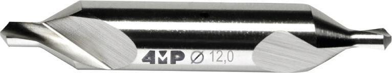
HSS Drilling, HSS drills 01 Perçage monobloc Solid drilling D1 D2 L2 L1 Punta HSS-E a centrare DCB150U
DCB150U HSSE-Co5%
Articolo Reference D1 (mm) D2 (mm) L1 (mm) L2 (mm) Avanzamento (mm/giro) Feed Codice Code DCB150U-040-A0-4MP 4 4 52 12 0,08 - 0,10 71 182 789 DCB150U-060-A0-4MP 6 6 66 20 0,15 - 0,25 71 182 797 DCB150U-080-A0-4MP 8 8 79 25 0,15 - 0,25 71 182 800 DCB150U-100-A0-4MP 10 10 89 25 0,15 - 0,25 71 182 819 DCB150U-120-A0-4MP 12 12 102 30 0,15 - 0,25 71 182 827 DCB150U-160-A0-4MP 16 16 115 35 0,20 - 0,30 71 182 835 D2 D1 L2 L1 Punta da centro HSS DCA100U Punta da centro HSS 60° Norma ISO NFE 66051-A DIN 333-A / JIS-1 Non rivestito Applicazione universale HSS center drill DCA100U 60° HSS center drill Norm ISO NFE 66051-A DIN 333-A / JIS-1 Uncoated Universal application Articolo Reference D1 (mm) D2 (mm) L1 (mm) Lunghezza L2 min max Length L2 Avanzamento (mm/giro) Feed Codice Code DCA100U-040X1-A0-4MP 4 1 35 1,3 ~ 1,7 0,08 - 0,10 71 182 649 DCA100U-040X1.6-A0-4MP 4 1,6 35 2 ~ 2,6 0,08 - 0,10 71 182 657 DCA100U-050X1.5-A0-4MP 5 1,5 40 2 ~ 2,6 0,08 - 0,10 71 182 665 DCA100U-050X2-A0-4MP 5 2 40 2,5 ~ 3,1 0,08 - 0,10 71 182 673 DCA100U-060X2-A0-4MP 6 2 45 2,5 ~ 3,1 0,08 - 0,10 71 182 681 DCA100U-063X2.5-A0-4MP 6,3 2,5 45 3,1 ~ 3,8 0,08 - 0,10 71 182 703 DCA100U-080X2.5-A0-4MP 8 2,5 50 3,1 ~ 3,8 0,08 - 0,10 71 182 711 DCA100U-080X3.15-A0-4MP 8 3,15 50 3,1 ~ 3,8 0,08 - 0,10 71 182 738 DCA100U-100X3-A0-4MP 10 3 55 3,9 ~ 4,6 0,08 - 0,10 71 182 746 DCA100U-100X4-A0-4MP 10 4 55 5 ~ 5,9 0,08 - 0,10 71 182 754 DCA100U-120X4-A0-4MP 12 4 63 5 ~ 5,9 0,08 - 0,10 71 182 762 DCA100U-125X5-A0-4MP 12 5 63 6,3 ~ 7,2 0,08 - 0,10 71 182 770
Foratura, punte in acciaio
HSSE-Co5% Per centratura e smussatura in un’unica operazione HSS-E spotting drill
Centering
Foratura, punte in acciaio HSS Drilling, HSS drills
37 01 Foratura integrale / Solid drilling
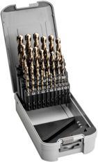
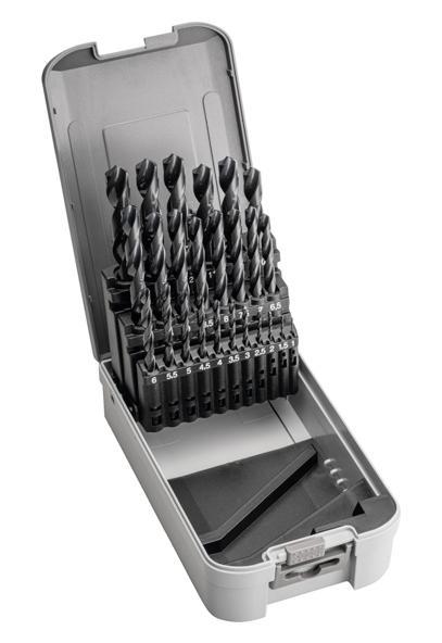
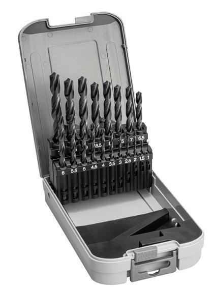
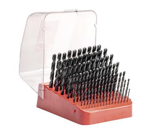
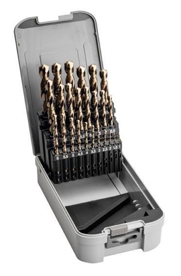
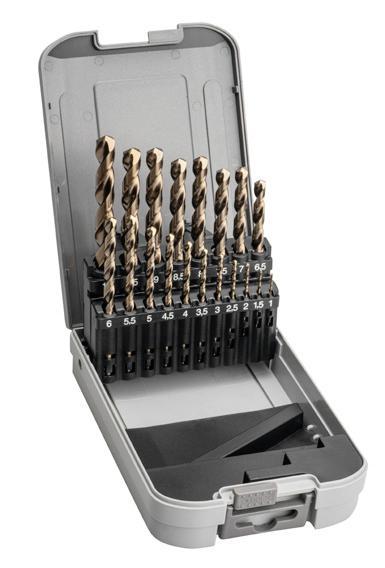
Set di 25 punte HSS DCA810U Capacità da 1 a 13 mm per 0,5 mm Set of 25 HSS drills DCA810U Capacity 1 to 13 mm per 0,5 mm Articolo Reference Codice Code SET25-DCA810U-1-13-4MP 71 178 692 Set di 19 punte HSS DCA810U Capacità da 1 a 10 mm per 0,5 mm Set of 19 HSS drills DCA810U Capacity 1 to 10 mm per 0,5 mm Articolo Reference Codice Code SET19-DCA810U-1-10-4MP 71 178 714 Set di 91 punte HSS DCA810U Capacità da 1 a 10 mm per 0,1 mm Set of 91 HSS drills DCA810U Capacity 1 to 10 mm per 0,1 mm Articolo Reference Codice Code SET91-DCA810U-1-10-4MP 71 178 749 Set di 25 punte HSS-E DCB890U Capacità da 1 a 13 mm per 0,5 mm Set of 25 HSS-E drills DCB890U Capacity 1 to 13 mm per 0,5 mm Articolo Reference Codice Code SET25-DCB890U-1-13-4MP 71 178 706 Set di 19 punte HSS-E DCB890U Capacità da 1 a 10 mm per 0,5 mm Set of 19 HSS-E drills DCB890U Capacity 1 to 10 mm per 0,5 mm Articolo Reference Codice Code SET19-DCB890U-1-10-4MP 71 178 722
38 Codifica Designation system GAMMA DEI
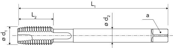
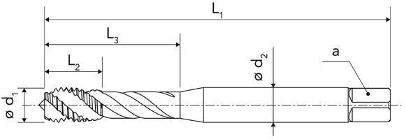
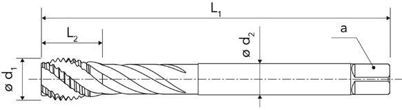
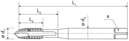
A MACCHINA OVERVIEW OF MACHINE TAPS Masch�o Tap 1 D – Dritto D - Stra � ght flute H – Elicoidale H - Hel � cal flutes N – Deformazione N - Form � ng tap T�po Type 2 1 - Metrica 1 - Metr � c 2 - Metrica acciaio 2 - Metr � c steel 3 - Metrica Acciaio inossidabile 3 -Sta � nless steel metr � c 4 - Metrica alluminio 4 - Alum � num metr � c 5 - Metrica fine 5 - F � ne metr � c 6 - GAS 6 - GAS 7 - UNC Gamma Range 3 1 - Non rivestito 0 - Uncoated 1 - VAP 2 - TIN 3 - ALTIN 4 - TICN 5 - TIALN 9 - SPECIALE 9 - Specıal R�vest�mento Coat�ng 4 0 - Prima generazione 0 - F � rst generat � on Generaz�one Generat�on 5 U - Universale U – Un � verselle P - Acciaio P - Steel K - Ghisa K - Cast � ron M - Acciaio inossidabile M - Sta � nless steel S - Superlega S - H � gh temperature alloy H - Acciaio duro H - Hard steel N - Alluminio N - Alum � num C – Composito C - Compos � te Appl�caz�one Appl�cat�on 6 M8 7 T 1 U 6 D 2 1 3 0 4 0 5D�ametro DC DC d�ameter 7 Maschiatura integrale / Solid taping
MASCHI
Gamma dei maschi a macchina Overview of machine taps
inossidabile Stainless steel
Acciaio inossidabile Stainless steel Alluminio Aluminum Alluminio Aluminum
Universale sinterizzato Universal optimized
Universale sinterizzato Universal optimized Universale Universal Universale Universal Universale Universal Universale Universal Universale Universal Universale Universal
Gamma Ø (mm) Ø range (mm) M3 - M24M3 - M20M3 - M16M3 - M16M3 - M16M3 - M16M3 - M12M3 - M12M3 - M12M3
Condizioni di taglio Cutting parameter Vc (m/mn) Vc (m/mn)
39
Pagina catalogo : Page catalogue : P.40P.40P.41P.41P.42P.42P.43P.43P.44P.44 P.45 P.45 P.46 P.46P.47P.47 Serie Series TD110UTH110UTD220PTH220PTD350MTH350MTD410NTH400NTN190U TN190U6G TD500UTH500UTD610UTH610UTD700UTH700U Materiale Material HSSEHSSEHSSE-PMHSSE-PMHSSE-PMHSSE-PMHSSEHSSEHSSE-PMHSSE-PMHSSEHSSEHSSEHSSEHSSEHSSE Filettatura Threading METRICO METRIC METRICO METRIC METRICO METRIC METRICO METRIC METRICO METRIC METRICO METRIC METRICO METRIC METRICO METRIC METRICO METRIC METRICO METRIC METRICO FINE METRIC METRICO FINE METRIC» GAZ GAS GAZ GAS UNC UNC Tolleranza Tolerance ISO 2 (6H) ISO 2 (6H) 6HX 6HX 6HX 6HX ISO 2 (6H) ISO 2 (6H) 6HX 6GX ISO 2 (6H) ISO 2 (6H) ISO 5969ISO 59692B 2B
materiale Material application Universale Universal Universale Universal Universale sinterizzato Universal optimized Universale sinterizzato Universal optimized Acciaio
Applicazione
1"1/8
- M12M4 - M16M4 - M161/8 -
- 3/4N4 - 3/4N4 - 3/4
Vc (m/mn) Vc (m/mn) Vc (m/mn) Vc (m/mn) Vc (m/mn) Vc (m/mn) Vc (m/mn) Vc (m/mn) Vc (m/mn) Vc (m/mn) Vc (m/mn) Vc (m/mn) Vc (m/mn) Vc (m/mn) Applicazioni / Applications P Acciaio non legato Non alloyed steel O 10 - 15 O 8 - 12 O 20 - 30 O 15 - 25 O 18 - 20 O 40 - 45 O 40 - 45 O 20 - 25 O 12 - 15 O 20 - 25 O 12 - 15 O 20 - 25 O 12 - 15 Acciaio bassolegato Low alloyed steel O 8 - 10 O 6 - 8 O 10 - 20 O 5 - 15 O 35 - 40 O 35 - 40 O 15 - 20 O 10 - 12 O 15 - 20 O 10 - 12 O 15 - 20 O 10 - 12 Acciaio legato Alloyed steel 6 - 8 5 - 6 8 - 10 5 - 8 O 18 - 20 O 15 - 20 O 15 - 20 O 15 - 20 O 12 - 15 6 - 8 O 12 - 15 6 - 8 O 12 - 15 6 - 8 M Acciaio inossidabile, duplex Duplex stainless steel 6 - 8 5 - 7 O 10 - 12 O 8 - 10 2 - 3 6 - 8 2 - 3 6 - 8 2 - 3 6 - 8 Acciaio inossidabile autentico Autenetic stainless steel 6 - 8 5 - 6 10 - 20 10 - 15 O 18 - 20 O 15 - 20 O 15 - 20 O 15 - 20 5 - 7 5 - 7 5 - 7 Acciaio inossidabile molto tenace e altamente legato Precipitation hardening stainless steel O 10 - 12 O 8 - 10 K Ghisa grigia Grey cast iron O 12 - 15 O 10 - 12 Ghisa lamellare Nodular cast iron O 10 - 12 O 8 - 10 Ghisa malleabile Malleable cast iron 10 - 12 8 - 10 O 25 - 35 O 20 - 30 O 15 - 20 O 12 - 15 O 15 - 20 O 12 - 15 O 15 - 20 O 12 - 15 S Superlega a base di ferro Fer based alloy Superlega a base di cobalto Co-based alloy Superleghe a base di nichel Ni-based alloy O 3 - 4 O 2 - 3 O 12 - 18 O 10 - 15 O 5 - 10 O 5 - 10 8 - 10 6 - 8 8 - 10 6 - 8 8 - 10 6 - 8 8 - 10 Lega di titanio Ti-alloy N Alluminio < 9% Aluminum < 9% O 18 - 20 O 12 - 15 O 40 - 45 O 40 - 45 O 15 - 25 18 - 20 O 15 - 25 18 - 20 O 15 - 25 18 - 20 Lega di alluminio Aluminum alloy 15 - 18 12 - 15 O 30 - 40 O 25 - 35 O 15 - 18 O 12 - 15 O 40 - 45 O 40 - 45 O 15 - 18 O 15 - 18 O 15 - 18 O 15 - 18 O 15 - 18 O 15 - 18 H Acciaio cementato, per utensili, temprato Hardened steel Maschiatura integrale / Solid taping
Maschiatura, maschi a macchina
Taping, machine taps
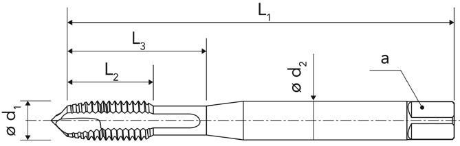
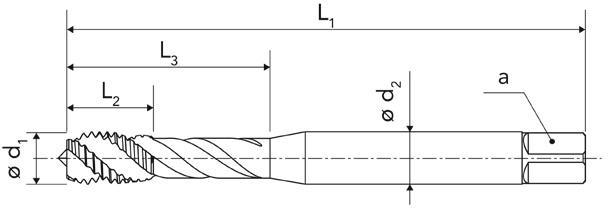
Maschio a macchina in HSS-E per foro passante
TD110U
Per maschiatura metrica (M)
Trattamento VAP per una migliore resistenza all’usura
Consigliato per acciai < 1100 N/mm2
HSS-E through hole machine tap TD110U
For metric threading (M)
VAP treatment for good wear resistance For steel < 1100N/mm� Articolo
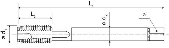
Maschio a macchina in HSS-E per foro cieco TH110U
Per maschiatura metrica (M) Trattamento VAP per una migliore resistenza all’usura
Consigliato per acciai < 1100 N/mm2
HSS-E blind hole machine tap
TH110U
For metric threading (M)
VAP treatment for good wear resistance For steel < 1100N/mm�
01 Maschiatura integrale / Solid taping
40
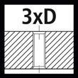
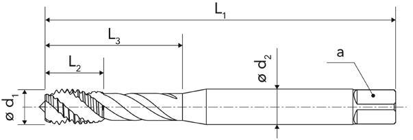
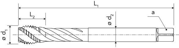
Reference d1 (mm) Passo (mm) Pitch L1 (mm) L2 (mm) L3 (mm) d2 (mm) a (mm) Norme Norm Ø Foratura (mm) Drilling Codice Code TD110U-M3-4MP M3 0,5 56 9 18 3,5 2,7 DIN 371 2,5 71 171 272 TD110U-M4-4MP M4 0,7 63 12 21 4,5 3,4 DIN 371 3,3 71 171 280 TD110U-M5-4MP M5 0,8 70 13 25 6 4,9 DIN 371 4,2 71 171 299 TD110U-M6-4MP M6 1 80 15 30 6 4,9 DIN 371 5 71 171 302 TD110U-M8-4MP M8 1,25 90 18 35 8 6,2 DIN 371 6,8 71 171 310 TD110U-M10-4MP M10 1,5 100 20 39 10 8 DIN 371 8,5 71 171 329 TD110U-M12-4MP M12 1,75 110 23 - 9 7 DIN 37610,2 71 171 337 TD110U-M14-4MP M14 2 110 25 - 11 9 DIN 37612 71 171 345 TD110U-M16-4MP M16 2 110 25 - 12 9 DIN 37614 71 171 353 TD110U-M20-4MP M202,5 140 30 - 16 12 DIN 37617,5 71 171 361 TD110U-M24-4MP M243 160 36 - 18 14,5 DIN 37621 71 171 388 2.5
Articolo Reference d1 (mm) Passo (mm) Pitch L1 (mm) L2 (mm) L3 (mm) d2 (mm) a (mm) Norme Norm Ø Foratura (mm) Drilling Codice Code TH110U-M3-4MP M3 0,5 56 5 18 3,5 2,7 DIN 371 2,5 71 171 167 TH110U-M4-4MP M4 0,7 63 7 21 4,5 3,4 DIN 371 3,3 71 171 175 TH110U-M5-4MP M5 0,8 70 8 25 6 4,9 DIN 371 4,2 71 171 183 TH110U-M6-4MP M6 1 80 10 30 6 4,9 DIN 371 5 71 171 191 TH110U-M8-4MP M8 1,25 90 13 35 8 6,2 DIN 371 6,8 71 171 205 TH110U-M10-4MP M10 1,5 100 15 39 10 8 DIN 371 8,5 71 171 213 TH110U-M12-4MP M12 1,75 110 18 - 9 7 DIN 37610,2 71 171 221 TH110U-M14-4MP M14 2 110 20 - 11 9 DIN 37612 71 171 248 TH110U-M16-4MP M16 2 110 20 - 12 9 DIN 37614 71 171 256 TH110U-M20-4MP M202,5 140 25 - 16 12 DIN 37617,5 71 171 264 DIN 371 DIN 371 DIN 376 DIN 376
Maschiatura, maschi a macchina
Taping, machine taps
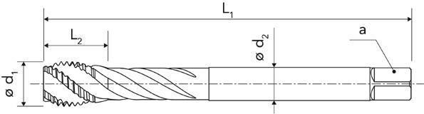
Maschio a macchina in HSSEPM per foro passante TD220P
Per maschiatura metrica (M)
Rivestimento in tin
Maschio sinterizzato per acciaio duro > 1100 N/mm2
P M
HSSE-PM through hole machine tap TD220P
For metric threading (M)
Tin coating
Optimized tap for hard steel > 1100 N/mm�
Maschio a macchina in HSSE-PM per foro cieco
TH220P
Per maschiatura metrica (M)
Rivestimento in tin
Maschio sinterizzato per acciaio duro > 1100 N/mm2
P M
HSSE-PM blind hole machine tap TH220P For metric threading (M) Tin coating Optimized tap for hard steel > 1100 N/mm�
01 Maschiatura integrale / Solid taping
41
Reference d1 (mm) Passo (mm) Pitch L1 (mm) L2 (mm) L3 (mm) d2 (mm) a (mm) Norme Norm Ø Foratura (mm) Drilling Codice Code TD220P-M3-4MP M3 0,5 56 10 18 3,5 2,7 DIN 371 2,5 71 171 485 TD220P-M4-4MP M4 0,7 63 12 21 4,5 3,4 DIN 371 3,3 71 171 493 TD220P-M5-4MP M5 0,8 70 14 24,56 4,9 DIN 371 4,2 71 171 507 TD220P-M6-4MP M6 1 80 16 29 6 4,9 DIN 371 5 71 171 515 TD220P-M8-4MP M8 1,25 90 18 33 8 6,2 DIN 371 6,8 71 171 523 TD220P-M10-4MP M10 1,5 100 20 36 10 8 DIN 3768,5 71 171 531 TD220P-M12-4MP M12 1,75 110 24 - 9 7 DIN 37610,2 71 171 558 TD220P-M16-4MP M16 2 110 28 - 12 9 DIN 37614 71 171 566
Articolo
Articolo Reference d1 (mm) Passo (mm) Pitch L1 (mm) L2 (mm) L3 (mm) d2 (mm) a (mm) Norme Norm Ø Foratura (mm) Drilling Codice Code TH220P-M3-4MP M3 0,5 56 7 15 3,5 2,7 DIN 371 2,5 71 171 396 TH220P-M4-4MP M4 0,7 63 8,5 21 4,5 3,4 DIN 371 3,3 71 171 418 TH220P-M5-4MP M5 0,8 70 10 24,56 4,9 DIN 371 4,2 71 171 426 TH220P-M6-4MP M6 1 80 12 29 6 4,9 DIN 371 5 71 171 434 TH220P-M8-4MP M8 1,25 90 14 33 8 6,2 DIN 371 6,8 71 171 442 TH220P-M10-4MP M10 1,5 100 17 39 10 8 DIN 371 8,5 71 171 450 TH220P-M12-4MP M12 1,75 110 18 - 9 7 DIN 37610,2 71 171 469 TH220P-M16-4MP M16 2 110 20,5- 12 9 DIN 37614 71 171 477 DIN 371 DIN 376 DIN 371 DIN 376
Maschiatura, maschi a macchina
Taping, machine taps

Maschio a macchina in HSSE-PM per foro passante TD350M
Per maschiatura metrica (M)
Rivestimento TIALN Maschio sinterizzato per acciaio inossidabile
P M
HSSE-PM through hole machine tap TD350M
For metric threading (M) TIALN coating
Optimized tap for stainless steel
Maschio a macchina in HSSE-PM per foro cieco
TH350M Per maschiatura metrica (M)
Rivestimento TIALN Maschio sinterizzato per acciaio inossidabile
P M
HSSE-PM blind hole machine tap TH350M For metric threading (M) TIALN coating Optimized tap for stainless steel
01 Maschiatura integrale / Solid taping
42
d1 (mm) Passo (mm) Pitch L1 (mm) L2 (mm) L3 (mm) d2 (mm) a (mm) Norme Norm Ø Foratura (mm) Drilling Codice Code TD350M-M3-4MP M3 0,5 56 10 18 3,5 2,7 DIN 371 2,5 71 171 655 TD350M-M4-4MP M4 0,7 63 12 21 4,5 3,4 DIN 371 3,3 71 171 663 TD350M-M5-4MP M5 0,8 70 14 24,56 4,9 DIN 371 4,2 71 171 671 TD350M-M6-4MP M6 1 80 16 29 6 4,9 DIN 371 5 71 171 698 TD350M-M8-4MP M8 1,25 90 18 33 8 6,2 DIN 371 6,8 71 171 701 TD350M-M10-4MP M10 1,5 100 20 36 10 8 DIN 371 8,5 71 171 728 TD350M-M12-4MP M12 1,75 110 24 - 9 7 DIN 37610,2 71 171 736 TD350M-M16-4MP M16 2 110 28 - 12 9 DIN 37614 71 171 744
Articolo Reference
Articolo Reference d1 (mm) Passo (mm) Pitch L1 (mm) L2 (mm) L3 (mm) d2 (mm) a (mm) Norme Norm Ø Foratura (mm) Drilling Codice Code TH350M-M3-4MP M3 0,5 56 7 15 3,5 2,7 DIN 371 2,5 71 171 574 TH350M-M4-4MP M4 0,7 63 8,5 21 4,5 3,4 DIN 371 3,3 71 171 582 TH350M-M5-4MP M5 0,8 70 10 24,56 4,9 DIN 371 4,2 71 171 590 TH350M-M6-4MP M6 1 80 12 29 6 4,9 DIN 371 5 71 171 604 TH350M-M8-4MP M8 1,25 90 14 33 8 6,2 DIN 371 6,8 71 171 612 TH350M-M10-4MP M10 1,5 100 17 39 10 8 DIN 371 8,5 71 171 620 TH350M-M12-4MP M12 1,75 110 18 - 9 7 DIN 37610,2 71 171 639 TH350M-M16-4MP M16 2 110 20,5- 12 9 DIN 37614 71 171 647 DIN 371 DIN 376 DIN 371 DIN 376
Maschiatura, maschi a macchina
Taping, machine taps
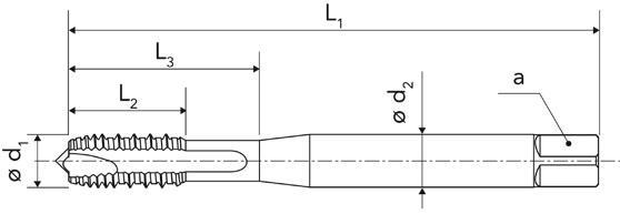
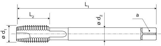
Maschio a macchina in HSS-E per foro passante TD410N
Per maschiatura metrica (M) Denti alternati
Maschio sinterizzato per alluminio e non ferrosi
HSS-E through hole machine tap TD410N
For metric threading (M) Optimized tap for aluminum and non ferrous
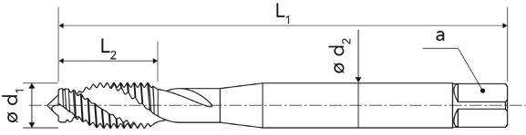
Maschio a macchina in HSS-E per foro cieco TH400N
Per maschiatura metrica (M) Maschio sinterizzato per alluminio e non ferrosi
HSS-E blind hole machine tap
TH410N
For metric threading (M) Optimized tap for Aluminum and non ferrous
01 Maschiatura integrale / Solid taping
43
Articolo Reference d1 (mm) Passo (mm) Pitch L1 (mm) L2 (mm) L3 (mm) d2 (mm) a (mm) Norme Norm Ø Foratura (mm) Drilling Codice Code TD410N-M3-4MP M3 0,5 56 10 18 3,5 2,7 DIN 371 2,5 71 171 825 TD410N-M4-4MP M4 0,7 63 12 21 4,5 3,4 DIN 371 3,3 71 171 833 TD410N-M5-4MP M5 0,8 70 14 24,56 4,9 DIN 371 4,2 71 171 841 TD410N-M6-4MP M6 1 80 16 29 6 4,9 DIN 371 5 71 171 868 TD410N-M8-4MP M8 1,25 90 18 33 8 6,2 DIN 371 6,8 71 171 876 TD410N-M10-4MP M10 1,5 100 20 36 10 8 DIN 371 8,5 71 171 884 TD410N-M12-4MP M12 1,75 110 24 - 9 7 DIN 37610,2 71 171 892 2.5
Articolo Reference d1 (mm) Passo (mm) Pitch L1 (mm) L2 (mm) L3 (mm) d2 (mm) a (mm) Norme Norm Ø Foratura (mm) Drilling Codice Code TH400N-M3-4MP M3 0,5 56 10 18 3,5 2,7 DIN 371 2,5 71 171 752 TH400N-M4-4MP M4 0,7 63 12 21 4,5 3,4 DIN 371 3,3 71 171 760 TH400N-M5-4MP M5 0,8 70 14 24,56 4,9 DIN 371 4,2 71 171 779 TH400N-M6-4MP M6 1 80 16 29 6 4,9 DIN 371 5 71 171 787 TH400N-M8-4MP M8 1,25 90 18 33 8 6,2 DIN 371 6,8 71 171 795 TH400N-M10-4MP M10 1,5 100 20 36 10 8 DIN 371 8,5 71 171 809 TH400N-M12-4MP M12 1,75 110 24 - 9 7 DIN 37610,2 71 171 817 DIN 371 DIN 376 DIN 371 DIN 376
Maschiatura, maschi a macchina
Taping, machine taps
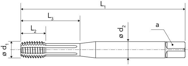
Maschio a macchina
HSSE-PM per rullatura
TN190U
Per maschiatura metrica (M)
Per maschiatura a rullare con scanalature di lubrificazione
HSSE-PM Thread former machine tap TN190U
For metric threading (M)
For thread forming with lubrication grooves
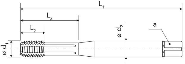
Maschio a macchina
HSSE-PM per rullatura
TN190U-6G
Per maschiatura metrica (M)
Per maschiatura a rullare con scanalature di lubrificazione
HSSE-PM Thread former machine tap TN190U-6G
For metric threading (M) For thread forming with lubrication grooves
01 Maschiatura integrale / Solid taping
44
P M
Articolo Reference d1 (mm) Passo (mm) Pitch L1 (mm) L2 (mm) L3 (mm) d2 (mm) a (mm) Norme Norm Ø Foratura (mm) Drilling Codice Code TN190U-M3-4MP M3 0,5 56 5 17 3,5 2,7 DIN 21742,8 71 172 465 TN190U-M4-4MP M4 0,7 63 7 21 4,5 3,4 DIN 21743,7 71 172 473 TN190U-M5-4MP M5 0,8 70 8 25 6 4,9 DIN 21744,65 71 172 481 TN190U-M6-4MP M6 1 80 10 29 6 4,9 DIN 21745,6 71 172 503 TN190U-M8-4MP M8 1,25 90 13 35 8 6,2 DIN 21747,45 71 172 511 TN190U-M10-4MP M10 1,5 100 15 39 10 8 DIN 21749,35 71 172 538 TN190U-M12-4MP M12 1,75 110 18 - 9 7 DIN 217411,25 71 172 546
P M G Articolo Reference d1 (mm) Passo (mm) Pitch L1 (mm) L2 (mm) L3 (mm) d2 (mm) a (mm) Norme Norm Ø Foratura (mm) Drilling Codice Code TN190U-M3.6G-4MP M3 0,5 56 5 17 3,5 2,7 DIN 21742,8 71 172 554 TN190U-M4.6G-4MP M4 0,7 63 7 21 4,5 3,4 DIN 21743,7 71 172 562 TN190U-M5.6G-4MP M5 0,8 70 8 25 6 4,9 DIN 21744,65 71 172 570 TN190U-M6.6G-4MP M6 1 80 10 29 6 4,9 DIN 21745,6 71 172 589 TN190U-M8.6G-4MP M8 1,25 90 13 35 8 6,2 DIN 21747,45 71 172 597 TN190U-M10.6G-4MP M10 1,5 100 15 39 10 8 DIN 21749,35 71 172 600 TN190U-M12.6G-4MP M12 1,75 110 18 - 9 7 DIN 217411,25 71 172 619
2174
DIN 2174 DIN
Maschiatura, maschi a macchina
Taping, machine taps

Maschio a macchina in HSS-E per foro passante
TD500U
Per maschiatura metrica fine (MF) Consigliato per acciai < 1100 N/mm2
HSS-E through hole machine tap TD500U For fine metric threading (MF) For steel < 110N/mm�
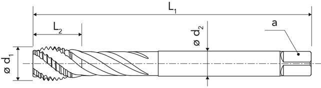
(MF) Consigliato per acciai < 1100 N/mm2
HSS-E blind hole machine tap TH500U
For fine metric threading (MF) For steel < 110N/mm�
01 Maschiatura integrale / Solid taping
45
Articolo Reference d1 (mm) Passo (mm) Pitch L1 (mm) L2 (mm) L3 (mm) d2 (mm) a (mm) Norme Norm ØForatura (mm) Drilling Codice Code TD500U-MF4X0.5-4MP MF40,5 63 12 - 2,8 2,1 DIN 3743,5 71 172 007 TD500U-MF5X0.5-4MP MF50,5 70 14 - 3,5 2,7 DIN 3744,5 71 172 015 TD500U-MF6X0.75-4MP MF60,7580 16 - 4,5 3,4 DIN 3745,2 71 172 023 TD500U-MF8X1-4MP MF81 90 16 - 6 4,9 DIN 3747 71 172 031 TD500U-MF10X1-4MP MF101 100 18 - 7 5,5 DIN 3749 71 172 058 TD500U-MF12X1-4MP MF121 110 22 - 9 7 DIN 37411 71 172 066 TD500U-MF12X1.5-4MP MF121,5 110 22 - 9 7 DIN 37410,5 71 172 074 TD500U-MF16X1-4MP MF161 110 22 - 12 9 DIN 37415 71 172 082 TD500U-MF16X1.5-4MP MF161,5 110 22 - 12 9 DIN 37414,5 71 172 090 2.5
a macchina in HSS-E per foro cieco TH500U
fine
Maschio
Per maschiatura metrica
Articolo Reference d1 (mm) Passo (mm) Pitch L1 (mm) L2 (mm) L3 (mm) d2 (mm) a (mm) Norme Norm Ø Foratura (mm) Drilling Codice Code TH500U-MF4X0.5-4MP MF40,5 63 4,9 - 2,8 2,1 DIN 3743,5 71 171 906 TH500U-MF5X0.5-4MP MF50,5 70 6,4 - 3,5 2,7 DIN 3744,5 71 171 914 TH500U-MF6X0.75-4MP MF60,7580 7,5 - 4,5 3,4 DIN 3745,2 71 171 922 TH500U-MF8X1-4MP MF81 90 10 - 6 4,9 DIN 3747 71 171 930 TH500U-MF10X1-4MP MF101 100 10 - 7 5,5 DIN 3749 71 171 949 TH500U-MF12X1-4MP MF121 110 13 - 9 7 DIN 37411 71 171 957 TH500U-MF12X1.5-4MP MF121,5 110 14 - 9 7 DIN 37410,5 71 171 965 TH500U-MF16X1-4MP MF161 110 14,5 - 12 9 DIN 37415 71 171 973 TH500U-MF16X1.5-4MP MF161,5 110 15,5 - 12 9 DIN 37414,5 71 171 981 DIN 374 DIN 374
Maschiatura, maschi a macchina
Taping, machine taps
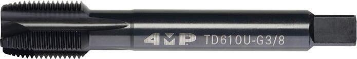
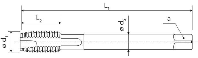
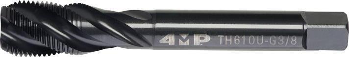
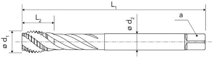
Maschio a macchina in HSS-E per foro passante
through hole machine tap
01 Maschiatura integrale / Solid taping
46
TD610U
TD610U For withworth threading (G) Norm EN ISO 228 For steel < 1100 N/mm� Articolo Reference d1 (mm) Passo (mm) Pitch L1 (mm) L2 (mm) L3 (mm) d2 (mm) a (mm) Norme Norm ØForatura (mm) Drilling Codice Code TD610U-G1/8-4MP G1/828 90 18 - 7 5,5 DIN 51568,8 71 172 155 TD610U-G1/4-4MP G1/419 100 22 - 11 9 DIN 515611,8 71 172 163 TD610U-G3/8-4MP G3/819 100 22 - 12 9 DIN 515615,25 71 172 171 TD610U-G1/2-4MP G1/214 125 25 - 16 12 DIN 515619 71 172 198 TD610U-G3/4-4MP G3/414 140 28 - 20 16 DIN 515624,5 71 172 201 TD610U-G1-4MP G1 11 160 30 - 25 20 DIN 5156 30,75 71 172 228 2.5
a macchina in HSS-E per foro cieco TH610U Per maschiatura gas (G) Norma UNI EN ISO 228 Consigliato per acciai < 1100 N/mm2 HSS-E blind hole machine tap TH610U For withworth threading (G) Norm EN ISO 228 For steel < 1100 N/mm� Articolo Reference d1 (mm) Passo (mm) Pitch L1 (mm) L2 (mm) L3 (mm) d2 (mm) a (mm) Norme Norm ØForatura (mm) Drilling Codice Code TH610U-G1/8-4MP G1/828 90 17 - 7 5,5 DIN 51568,8 71 172 104 TH610U-G1/4-4MP G1/419 100 23 - 11 9 DIN 515611,8 71 172 112 TH610U-G3/8-4MP G3/819 100 23 - 12 9 DIN 515615,25 71 172 120 TH610U-G1/2-4MP G1/214 125 29 - 16 12 DIN 515619 71 172 139 TH610U-G3/4-4MP G3/414 140 29 - 20 16 DIN 515624,5 71 172 147 DIN 5156 DIN 5156
Per maschiatura gas (G) Norma UNI EN ISO 228 Consigliato per acciai < 1100 N/mm2 HSS-E
Maschio
Maschiatura, maschi a macchina
Taping, machine taps
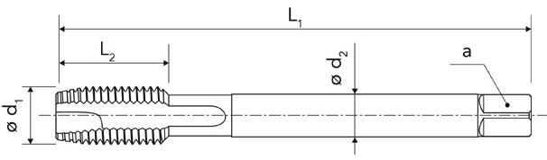
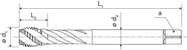
Maschio a macchina in HSS-E per foro passante
TD700U
Per maschiatura UNC
Norma ASME B1.1
Consigliato per acciai < 1100 N/mm2
HSS-E through hole machine tap TD700U
For UNC threading
Norm ASME B1.1 For steel < 1100 N/mm�
01 Maschiatura integrale / Solid taping
47
2B
Articolo Reference d1 (mm) Passo (mm) Pitch L1 (mm) L2 (mm) L3 (mm) d2 (mm) a (mm) Norme Norm Ø Foratura (mm) Drilling Codice Code TD700U-UNC.N4-4MP N4 11 56 10 18 3,5 2,7 DIN 2184-12,35 71 172 341 TD700U-UNC.N6-4MP N6 32 56 11 20 4 3 DIN 2184-12,85 71 172 368 TD700U-UNC.N8-4MP N8 32 63 13 22 4,5 3,4 DIN 2184-13,5 71 172 376 TD700U-UNC.N10-4MP N10 24 70 16 26,56 4,9 DIN 2184-13,9 71 172 384 TD700U-UNC.1/4-4MP 1/4 20 80 17 30 7 5,5 DIN 2184-15,1 71 172 392 TD700U-UNC.5/16-4MP 5/1618 90 18 - 6 4,9 DIN 2184-16,6 71 172 406 TD700U-UNC.3/8-4MP 3/8 16 100 22 - 7 5,5 DIN 2184-18 71 172 414 TD700U-UNC.7/16-4MP 7/16 14 100 24 - 8 6,2 DIN 2184-19,4 71 172 422 TD700U-UNC.1/2-4MP 1/2 13 110 26 - 9 7 DIN 2184-110,8 71 172 430 TD700U-UNC.5/8-4MP 5/8 11 110 28 - 12 9 DIN 2184-113,5 71 172 449 TD700U-UNC.3/4-4MP 3/4 10 125 32 - 14 11 DIN 2184-116,5 71 172 457 2B 2.5
a macchina in HSS-E per foro cieco TH700U Per maschiatura UNC Norma ASME B1.1 Consigliato per acciai < 1100 N/mm2 HSS-E blind hole machine tap TH700U For UNC threading Norm ASME B1.1 For steel < 1100 N/mm� Articolo Reference d1 (mm) Passo (mm) Pitch L1 (mm) L2 (mm) L3 (mm) d2 (mm) a (mm) Norme Norm Ø Foratura (mm) Drilling Codice Code TH700U-UNC.N4-4MP N4 40 56 6,5 21 3,5 2,7 DIN 2184-12,35 71 172 236 TH700U-UNC.N6-4MP N6 32 56 7,5 22,54 3 DIN 2184-12,85 71 172 244 TH700U-UNC.N8-4MP N8 32 63 7,5 26 4,5 3,4 DIN 2184-13,5 71 172 252 TH700U-UNC.N10-4MP N10 24 70 10 28,56 4,9 DIN 2184-13,9 71 172 260 TH700U-UNC.1/4-4MP 1/4 20 80 11,5 32 7 5,5 DIN 2184-15,1 71 172 279 TH700U-UNC.5/16-4MP 5/1618 90 13 - 6 4,9 DIN 2184-16,6 71 172 287 TH700U-UNC.3/8-4MP 3/8 16 100 14 - 7 5,5 DIN 2184-18 71 172 295 TH700U-UNC.7/16-4MP 7/16 14 100 17 - 8 6,2 DIN 2184-19,4 71 172 309 TH700U-UNC.1/2-4MP 1/2 13 110 19 - 9 7 DIN 2184-110,8 71 172 317 TH700U-UNC.5/8-4MP 5/8 11 110 22,5- 12 9 DIN 2184-113,5 71 172 325 TH700U-UNC.3/4-4MP 3/4 10 125 26 - 14 11 DIN 2184-116,5 71 172 333
Maschio
DIN 2184-1
DIN 2184-1
48 Fresatura integrale / Solid milling Codifica Designation system GAMMA DELLE FRESE IN CARBURO CARBIDE END MILLS OVERVIEW M 1 0 6 T 2 C 3 1 4 U 7 3 5 A 11 1 12 - 060 8R050 9 L20 10 Fresa M�ll 1 0 – Prima generazione 0 - F � rst generat � on Generaz�one Generat�on 6 A - Cilindrico A - Cyl � ndr � cal W - Weldon C - Cono morse C - Morse tapper Attacco Attachment 11 D – Dritto D - Stra � ght T - Torico T - Prof � l B - Emisferico B - Ball nose C - Smusso C - Chamfer � ng R - Sgrossatura R - Rough � ng F - Dinamico F - Dynam � c Forma Form 2 U - Universale U – Un � verselle P - Acciaio P - Steel K - Ghisa K - Cast � ron M - Acciaio inossidabile M - Sta � nless steel S - Superlega S - H � gh temperature alloy H - Acciaio duro H - Hard steel N - Alluminio N - Alum � num C – Composito C - Compos � te Appl�caz�one Appl�cat�on 7 1 - Interno 1 - Internal 0 – Esterno 0 - External Lubr�f�caz�one Coolant 12 C - Carburo C - Carb � de A - Acciaio A - Steel Mater�ale Mater�al 3 060 - 6,0 mm D�ametro DC DC d�ameter 8 1a gamma 1 - 1 st range 2a gamma 2 - 2 nd range Gamma Range 4 R - Raggio R - Corner rad � us C – Smusso C - Chamfer D�mens�one ragg�o / smusso Corner rad�us / chamfer d�mens�on 9 0 - Non rivestito 0 - Uncoated 1 - VAP 2 - TIN 3 - ALTIN 4 - TICN 5 - TIALN 9 - SPECIALE 9 - Specıal R�vest�mento Coat�ng 5 Lunghezza ut�l�zzab�le Useful length 10
Gamma delle frese in carburo
Carbide end mills overview
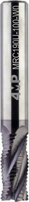
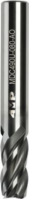
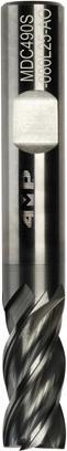


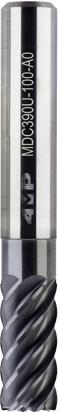
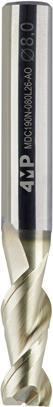
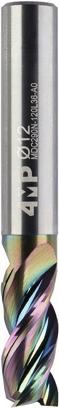


Condizioni di taglio
49 Fresatura integrale / Solid milling
Pagina catalogo : Page catalogue : P.50 P.50 P.51 P.51P.52P.52 P.53 P.53 P.54 P.54P.54P.55 P.55 P.56 P.56 Serie Series MDC150UMDC250UMDC550UMRC190UMDC490UMDC490SMFC190PMFC290UMDC390UMDC650UMBC150UMTC150UMCC100UMDC190N MDC290N Materiale Material CW CW CW CW CW CW CW CW CW CW CW CW CW CW CW Numero di denti (Z) Nr of teeth (Z) 3 4 4 4 4 4 5 5-7 6-8 6-8 2 4 2 2 3 Applicazione Application Gamma Ø (mm) Ø range (mm) 1 - 20 1 - 20 6 - 16 4 - 20 4 - 16 4 - 16 6 - 206 - 206 - 206 - 20 3 - 12 2 - 12 3 - 12 4 - 16 4 - 16
Cutting
Vc
Vc
Vc
Vc
Vc
Vc
Vc (m/mn) Vc (m/mn) Vc (m/mn) Vc (m/mn) Vc (m/mn) Vc (m/mn) Vc (m/mn) Vc (m/mn) Vc (m/mn) Ap = 0,5 x D Ae = 1 x D Ap = 1 x D Ae = 0,5 x D Ap 1 x D Ae = 0,1 x D Ap = 0,5 x D Ae = 1 x D Ap = 1 x D Ae = 1 x D Ap = 1 x D Ae = 1 x D Ap = 2,5 x D Ae = 0,2 x D Ap = 2,5 x D Ae = 0,1 x D Ap 1,5 x D Ae = 0,1 x D Ap 2 x D Ae = 0,1 x D Ap = 0,03 x D Ae = 0,3 x D Ap = 0,05 x D Ae = 0,05 x D Ap 1 x D Ae = 0,5 x D Ap = 1 x D Ae = 0,5 x D Ap = 1 x D Ae = 0,5 x D Applicazioni / Applications P Acciaio non legato Non alloyed steel O 90 - 100 O 60 - 70 O 150 - 170 O 130 - 150 O 130 - 140 O 100 - 120 O 300 - 340 O 280 - 300 O 270 - 300 O 200 - 220 O 400 - 450 O 160 - 180 O 90 - 110 Acciaio bassolegato Low alloyed steel O 60 - 70 O 50 - 60 O 130 - 150 O 130 - 150 O 100 - 110 O 200 - 230 O 190 - 210 O 180 - 220 O 180 - 200 O 260 - 280 O 140 - 160 O 70 - 90 Acciaio legato Alloyed steel O 45 - 50 O 40 - 45 O 100 - 120 O 130 - 150 O 80 - 90 O 130 - 150 O 160 - 180 O 150 - 200 O 160 - 180 O 220 - 240 O 110 - 120 O 50 - 60 M Acciaio inossidabile, duplex Duplex stainless steel O 30 - 35 O 40 - 60 O 50 - 60 O 80 - 110 O 80 - 110 O 60 - 70 Acciaio inossidabile autentico Autenetic stainless steel O 35 - 45 O 45 - 50 O 85 - 95 O 50 - 70 O 60 - 70 O 70 - 80 O 100 - 130 O 110 - 130 O 90 - 110 O 70 - 80 Acciaio inossidabile molto tenace e altamente legato Precipitation hardening stainless steel O 40 - 60 O 50 - 60 O 80 - 110 O 80 - 110 O 60 - 70 K Ghisa grigia Grey cast iron O 110 - 120 O 35 - 40 O 120 - 140 O 110 - 150 O 280 - 300 O 180 - 220 O 120 - 140 O 350 - 390 O 180 - 200 O 110 - 120 Ghisa lamellare Nodular cast iron O 100 - 110 O 35 - 40 O 90 - 110 O 110 - 130 O 240 - 260 O 140 - 160 O 110 - 120 O 340 - 375 O 160 - 180 O 80 - 90 Ghisa malleabile Malleable cast iron O 100 - 110 O 35 - 40 O 100 - 120 O 130 - 150 O 240 - 260 O 140 - 160 O 110 - 120 O 340 - 375 O 160 - 180 O 50 - 60 S Superlega a base di ferro Fer based alloy O 20 - 40 Superlega a base di cobalto Co-based alloy O 20 - 40 O 40 - 60 O 40 - 60 Superleghe a base di nichel Ni-based alloy O 20 - 40 O 25 - 30 O 50 - 70 O 50 - 70 Lega di titanio Ti-alloy O 30 - 50 O 35 - 40 O 80 - 120 O 90 - 110 N Alluminio < 9% Aluminium < 9% O 180 - 200 O 400 - 600 400 - 600 200 - 300 O 250 - 300 O 450 - 520 O 400 - 700 Lega di alluminio Aluminum alloy O 150 - 170 O 180 - 230 180 - 230 120 - 160 O 180 - 200 O 250 - 300 O 200 - 400 H Acciaio cementato, per utensili, temprato Hardened steel 140 - 160 80 - 110 * Per l’applicazione di scanalatura, ridurre la velocità di taglio del 25% * For slot milling, decrease the cutting speed of 25%
parameter
(m/mn)*
(m/mn)*
(m/mn)
(m/mn)
(m/mn)
(m/mn)
Frese in carburo integrale
Solid carbide end mills
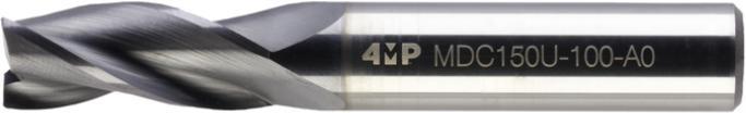


Consigliato per operazioni di scanalatura e contornatura
Solid carbide end mill 3 flutes
MDC150U
With corner protection 45°
Recommended tool for slotting and shoulder milling


01 50 Fresatura integrale / Solid milling
C X 45° D1 D2 L2 L1
Fresa in carburo integrale serie corta Z3 MDC150U
Con spigolo smussato a 45°
Reference ØD1 f8 (mm) ØD2 h5 (mm) L1 (mm) L2 (mm) C (mm) Tipo attacco Shank type Z Avanzamento fz (mm/giro) Feed fz Codice Code MDC150U-010-A0-4MP 1 4 40 3 0,05CYL 3 0,008 - 0,01 71 182 843 MDC150U-015-A0-4MP 1,5 4 40 4 0,05CYL 3 0,008 - 0,01 71 182 851 MDC150U-020-A0-4MP 2 4 40 5,5 0,05CYL 3 0,008 - 0,01 71 182 878 MDC150U-025-A0-4MP 2,5 4 40 6,5 0,05CYL 3 0,008 - 0,01 71 182 886 MDC150U-030-A0-4MP 3 6 50 8 0,1 CYL 3 0,008 - 0,01 71 182 894 MDC150U-040-A0-4MP 4 6 50 11 0,1 CYL 3 0,01 - 0,015 71 182 908 MDC150U-050-A0-4MP 5 6 50 13 0,1 CYL 3 0,012 - 0,01871 182 916 MDC150U-060-A0-4MP 6 6 50 13 0,1 CYL 3 0,015 - 0,02 71 182 924 MDC150U-080-A0-4MP 8 8 58 21 0,2 CYL 3 0,018 - 0,02571 182 932 MDC150U-100-A0-4MP 10 10 66 22 0,2 CYL 3 0,02 - 0,03 71 182 940 MDC150U-120-A0-4MP 12 12 73 26 0,3 CYL 3 0,025 - 0,03571 182 959 MDC150U-160-A0-4MP 16 16 83 36 0,3 CYL 3 0,035 - 0,04571 182 967 MDC150U-200-A0-4MP 20 20 92 41 0,3 CYL 3 0,045 - 0,06 71 182 975 D1 D2 L2 L1 Fresa in carburo integrale serie corta Z4 MDC250U Spigolo a lato Consigliato per operazioni di contornatura e finitura Solid carbide end mill 4 flutes MDC250U Sharp corner Recommended tool for shoulder millingand finishing Articolo Reference ØD1 f8 (mm) ØD2 h5 (mm) L1 (mm) L2 (mm) C (mm) Tipo attacco Shank type Z Avanzamento fz (mm/giro) Feed fz Codice Code MDC250U-010-A0-4MP 1 4 40 3 - CYL 4 0,008 - 0,01 71 182 983 MDC250U-015-A0-4MP 1,5 4 40 4 - CYL 4 0,008 - 0,01 71 182 991 MDC250U-020-A0-4MP 2 4 40 5,5 - CYL 4 0,008 - 0,01 71 183 009 MDC250U-025-A0-4MP 2,5 4 40 6,5 - CYL 4 0,008 - 0,01 71 183 017 MDC250U-030-A0-4MP 3 6 50 8 - CYL 4 0,008 - 0,01 71 183 025 MDC250U-040-A0-4MP 4 6 50 11 - CYL 4 0,01 - 0,015 71 183 033 MDC250U-050-A0-4MP 5 6 50 13 - CYL 4 0,012 - 0,01871 183 041 MDC250U-060-A0-4MP 6 6 50 13 - CYL 4 0,015 - 0,02 71 183 068 MDC250U-080-A0-4MP 8 8 58 21 - CYL 4 0,02 - 0,025 71 183 076 MDC250U-100-A0-4MP 10 10 66 22 - CYL 4 0,025 - 0,03 71 183 084 MDC250U-120-A0-4MP 12 12 73 26 - CYL 4 0,03 - 0,035 71 183 092 MDC250U-160-A0-4MP 16 16 83 36 - CYL 4 0,04 - 0,045 71 183 106 MDC250U-200-A0-4MP 20 20 92 41 - CYL 4 0,05 - 0,06 71 183 114
Articolo
Frese in carburo integrale
Solid carbide end mills


Spigolo a lato
Consigliato per operazioni di contornatura e finitura
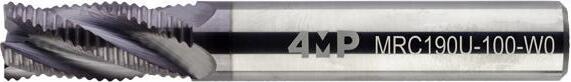


Solid carbide long end mill 4 flutes MDC550U Sharp corner
Recommended tool for shoulder millingand finishing
01 Fresatura integrale / Solid milling 51
D1 D2 L2 L1
Fresa in carburo integrale serie lunga Z4 MDC550U
Articolo Reference ØD1 h9 (mm) ØD2 h6 (mm) L1 (mm) L2 (mm) C (mm) Tipo attacco Shank type Z Avanzamento fz (mm/giro) Feed fz Codice Code MDC550U-060-A0-4MP 6 6 75 30 - WLD 4 0,03 - 0,05 71 183 637 MDC550U-080-A0-4MP 8 8 100 45 - WLD 4 0,03 - 0,06 71 183 645 MDC550U-100-A0-4MP 10 10 100 45 - WLD 4 0,035 - 0,07 71 183 653 MDC550U-120-A0-4MP 12 12 100 45 - WLD 4 0,04 - 0,09 71 183 661 MDC550U-160-A0-4MP 16 16 150 65 - WLD 4 0,045 - 0,12 71 183 688 C X 45° D1 D2 L2 L3 L1 D3
MRC190U
sgrossatura
spigolo
operazioni
sgrossatura in scanalatura
contornatura
carbide
mill MRC190U
Articolo Reference ØD1 f10 (mm) ØD2 h6 (mm) L1 (mm) L2 (mm) L3 (mm) D3 (mm) C (mm) Tipo attacco Shank type Z Avanzamento fz (mm/giro) Feed fz Codice Code MRC190U-040-A0-4MP 4 4 50 11 13 3,6 0,1 CYL 3 0,013 - 0,02571 183 181 MRC190U-050-A0-4MP 5 5 50 13 15 4,6 0,1 CYL 4 0,013 - 0,02571 183 203 MRC190U-060-A0-4MP 6 6 50 13 15 5,6 0,1 CYL 4 0,02 - 0,04 71 183 211 MRC190U-080-A0-4MP 8 8 58 21 23 7,6 0,1 CYL 4 0,02 - 0,04 71 183 238 MRC190U-100-W0-4MP 10 10 66 22 25 9,6 0,1 WLD 4 0,035 - 0,0571 183 246 MRC190U-120-W0-4MP 12 12 73 26 29 11,6 0,15 WLD 4 0,04 - 0,06 71 183 254 MRC190U-160-W0-4MP 16 16 83 36 40 15,6 0,15 WLD 4 0,055 - 0,0871 183 262 MRC190U-200-W0-4MP 20 20 92 41 46 19,6 0,2 WLD 4 0,07 - 0,10 71 183 270
Fresa in carburo integrale sgrossatura
Profilo di
Con
smussato a 45° Consigliato per
di
e
Solid
roughing end
Roughing profile With corner protection 45° Recommended tool in roughing for slotting and shoulder milling
Frese in carburo integrale
Solid carbide end mills
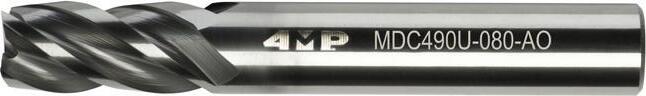


Fresa in carburo integrale ad alte prestazioni
MDC490U
Fresa ad alte prestazioni per ridurre le vibrazioni durante la lavorazione e migliorare la produttività.
Consigliato per applicazioni di scanalatura e contornatura


Fresa ad alte prestazioni per ridurre le vibrazioni durante la lavorazione e migliorare la produttività. Consigliato per applicazioni di scanalatura e contornatura
Solid carbide end mill high performance MDC490U
High performance end mill allowing to reduce vibration and increase productivity.
Recommended tool for slot and side milling
Solid carbide end mill high performance MDC490S
High performance end mill allowing to reduce vibration and increase productivity.
Recommended tool for slot and side milling
52
Fresatura integrale / Solid milling
01
D1 D2 L2 L1
Articolo Reference ØD1 h10 (mm) ØD2 h6 (mm) L1 (mm) L2 (mm) C (mm) Tipo attacco Shank type Z Avanzamento fz (mm/giro) Feed fz Codice Code MDC490U-040-A0-4MP 4 4 50 12 - CYL 4 0,010 - 0,02271 183 289 MDC490U-050-A0-4MP 5 5 50 13 - CYL 4 0,010 - 0,02271 183 297 MDC490U-060-A0-4MP 6 6 57 13 - CYL 4 0,02 - 0,03 71 183 300 MDC490U-080-A0-4MP 8 8 63 19 - CYL 4 0,03 - 0,05 71 183 319 MDC490U-100-A0-W0-4MP 10 10 72 22 - WLD 4 0,035 - 0,06 71 183 327 MDC490U-120-A0-W0-4MP 12 12 83 25 - WLD 4 0,035 - 0,06 71 183 335 MDC490U-160-A0-W0-4MP 16 16 92 32 - WLD 4 0,05 - 0,07 71 183 343 R D1 D2 L2 L3 L1
Fresa in carburo integrale ad alte prestazioni MDC490S
Articolo Reference ØD1 h10 (mm) ØD2 h6 (mm) L1 (mm) L2 (mm) L3 (mm) D3 (mm) R (mm) Tipo attacco Shank type Z Avanzamento fz (mm/giro) Feed fz Codice Code MDC490S-060L18-A0-4MP 6 6 57 13 18 5,8 0,3 CYL 4 0,02 - 0,03 71 184 005 MFC290U-080L25-A0-4MP 8 8 63 19 25 7,8 0,3 CYL 4 0,03 - 0,05 71 184 013 MDC490S-100L30-W0-4MP 10 10 72 22 30 9,8 0,3 WLD 4 0,035 - 0,0671 184 021 MDC490S-12034-W0-4MP 12 12 83 25 34 11,8 0,3 WLD 4 0,035 - 0,0671 184 048 MDC490S-160L42-W0-4MP 16 16 92 32 42 15,8 0,3 WLD 4 0,05 - 0,07 71 184 056 D3
Frese in carburo integrale
Solid carbide end mills

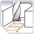
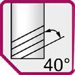
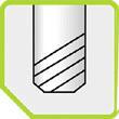

Fresa in carburo integrale dinamica MFC190P
Con rompitruciolo e spigolo smussato a 45°
Fresa ad alte prestazioni consigliata per la fresatura di acciaio in strategia trocoidale e dinamica in scanalatura e contornatura.


Con rompitruciolo e passaggio di refrigerante Fresa ad alte prestazioni consigliata per la fresatura in strategia trocoidale e dinamica in scanalatura e contornatura.
Dynamic solid carbide end mill
MFC190P
With chip-breaker and corner protection 45°
High performance end mill for steel Recommended for trochoidal and dynamic strategies in slot and shoulder milling.
Dynamic solid carbide end mill MFC290U
With chip-breaker and internal coolant High performance end mill Recommended for Trochoidal and dynamic strategies in slot and shoulder milling.
53 01 Fresatura integrale / Solid milling
L3 D1 D2 L2 L1 C X 45°
Articolo Reference ØD1 h9 (mm) ØD2 h6 (mm) L1 (mm) L2 (mm) L3 (mm) D3 (mm) C (mm) Tipo attacco Shank type Z Avanzamento fz (mm/giro) Feed fz Codice Code MFC190P-060L25-A0-4MP 6 6 62 18 25 5,8 0,1 CYL 5 0,05 - 0,06571 184 064 MFC190P-080L30-A0-4MP 8 8 68 24 30 7,8 0,15 CYL 5 0,06 - 0,07571 184 072 MFC190P-100L35-A0-4MP 10 10 80 30 35 9,8 0,2 CYL 5 0,07 - 0,10 71 184 080 MFC190P-120L45-A0-4MP 12 12 93 36 45 11,8 0,2 CYL 5 0,09 - 0,12 71 184 099 MFC190P-160L55-A0-4MP 16 16 108 48 55 15,8 0,3 CYL 5 0,11 - 0,15 71 184 102 MFC190P-200L70-A0-4MP 20 20 126 60 70 19,8 0,4 CYL 5 0,13 - 0,20 71 184 110 R D1 D2 L2 L1 L3
in
MFC290U
Fresa
carburo integrale dinamica
Articolo Reference ØD1 f9 (mm) ØD2 h6 (mm) L1 (mm) L2 (mm) L3 (mm) D3 (mm) R (mm) Tipo attacco Shank type Z Avanzamento fz (mm/giro) Feed fz Codice Code MFC290U-060R050L25-A1-4MP 6 6 62 18 25 5,6 0,5 CYL 5 0,027 - 0,04171 184 129 MFC290U-080R080L30-A1-4MP 8 8 68 24 30 7,6 0,8 CYL 5 0,04 - 0,06271 184 137 MFC290U-100R100L35-A1-4MP 10 10 80 30 35 9,6 1 CYL 5 0,055 - 0,082 71 184 145 MFC290U-120R120L45-A1-4MP 12 12 93 36 45 11,6 1,2 CYL 5 0,072 - 0,10 71 184 153 MFC290U-160R150L55-A1-4MP 16 16 108 48 55 15,6 1,5 CYL 7 0,10 - 0,144 71 184 161 MFC290U-200R200L70-A1-4MP 20 20 126 60 70 19,6 2 CYL 7 0,12 - 0,185 71 184 188 D3 D3
Frese in carburo integrale
Solid carbide end mills
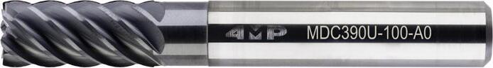

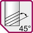

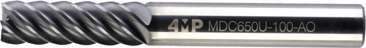

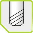

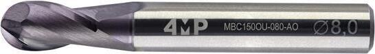

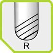
Consigliato per operazioni di finitura in contornatura
Solid carbide finishing end mill
54
Fresatura integrale / Solid milling
01
C X 45° D1 D2 L2 L3 L1 Fresa in
integrale
corta
MDC390U
carburo
serie
finitura
MDC390U
Articolo Reference ØD1 f9 (mm) ØD2 h6 (mm) L1 (mm) L2 (mm) L3 (mm) D3 (mm) C (mm) Tipo attacco Shank type Z Avanzamento fz (mm/giro) Feed fz Codice Code MDC390U-060-A0-4MP 6 6 50 13 15 5,6 0,1 CYL 6 0,027 - 0,04171 183 122 MDC390U-080-A0-4MP 8 8 58 21 23 7,6 0,1 CYL 6 0,041 - 0,06271 183 130 MDC390U-100-A0-4MP 10 10 66 22 25 9,6 0,1 CYL 6 0,055 - 0,082 71 183 149 MDC390U-120-A0-4MP 12 12 73 26 29 11,6 0,15 CYL 6 0,072 - 0,10371 183 157 MDC390U-160-A0-4MP 16 16 83 36 40 15,6 0,15 CYL 7 0,10 - 0,14 71 183 165 MDC390U-200-A0-4MP 20 20 92 41 46 19,6 0,2 CYL 8 0,12 - 0,185 71 183 173 C X 45° D1 D2 L2 L1 Fresa in carburo integrale serie lunga MDC650U Consigliato per operazioni di finitura in contornatura Solid carbide finishing long end mill MDC650U Recommended for finishing operations Articolo Reference ØD1 f8 (mm) ØD2 h5 (mm) L1 (mm) L2 (mm) C (mm) Tipo attacco Shank type Z Avanzamento fz (mm/giro) Feed fz Codice Code MDC650U-060-A0-4MP 6 6 62 18 0,1 CYL 6 0,015 - 0,02 71 183 718 MDC650U-080-A0-4MP 8 8 68 24 0,1 CYL 6 0,02 - 0,025 71 183 726 MDC650U-100-A0-4MP 10 10 80 30 0,1 CYL 6 0,025 - 0,03 71 183 734 MDC650U-120-A0-4MP 12 12 93 36 0,1 CYL 6 0,035 - 0,04571 183 742 MDC650U-160-A0-4MP 16 16 108 48 0,1 CYL 8 0,045 - 0,05 71 183 750 MDC650U-200-A0-4MP 20 20 126 60 0,1 CYL 8 0,05 - 0,065 71 183 769 D1 D2 L2 L1 R Fresa in carburo integrale semisferica serie corta MBC150U Consigliato per operazioni di profilatura e scanalatura negli acciai Solid carbide ball nose mill MBC150U Recommended for profiling and form operations in steel Articolo Reference ØD1 h9 (mm) ØD2 h6 (mm) L1 (mm) L2 (mm) R (mm) Tipo attacco Shank type Z Avanzamento fz (mm/giro) Feed fz Codice Code MBC150U-030-A0-4MP 3 3 50 6 1,5 CYL 2 0,007 - 0,01171 183 351 MBC150U-040-A0-4MP 4 4 54 8 2 CYL 2 0,025 - 0,03571 183 378 MBC150U-050-A0-4MP 5 5 54 10 2,5 CYL 2 0,025 - 0,03571 183 386 MBC150U-060-A0-4MP 6 6 54 12 3 CYL 2 0,032 - 0,04571 183 394 MBC150U-080-A0-4MP 8 8 58 14 4 CYL 2 0,040 - 0,05571 183 408 MBC150U-100-A0-4MP 10 10 66 18 5 CYL 2 0,045 - 0,06571 183 416 MBC150U-120-A0-4MP 12 12 73 22 6 CYL 2 0,045 - 0,06571 183 424 D3
Recommended for finishing operations
Frese in carburo integrale
Solid carbide end mills
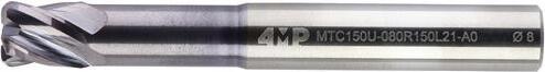
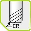
Consigliato per operazioni di contornatura e scanalatura su alluminio e non ferrosi
Solid carbide profile mill with corner radius MTC150U
Recommended for profiling and form operations in steel
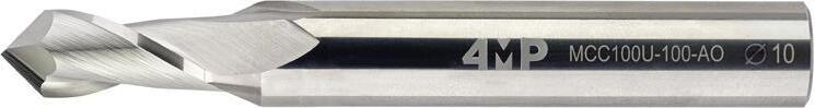


55 01 Fresatura integrale / Solid milling
R D1 D2 L3 L2 L1
in
Fresa
carburo integrale
torica Z4 MTC150U
Articolo Reference ØD1 h9 (mm) ØD2 h6 (mm) L1 (mm) L2 (mm) L3 (mm) D3 (mm) R (mm) Tipo attacco Shank type Z Avanzamento fz (mm/giro) Feed fz Codice Code MTC150U-020R020L21-A0-4MP 2 6 57 4 21 1,8 0,2 CYL 4 0,006 - 0,01171 183 432 MTC150U-020R050L21-A0-4MP 2 6 57 4 21 1,8 0,5 CYL 4 0,006 - 0,01171 183 440 MTC150U-030R030L21-A0-4MP 3 6 57 6 21 2,8 0,3 CYL 4 0,009 - 0,016 71 183 459 MTC150U-030R050L21-A0-4MP 3 6 57 6 21 2,8 0,5 CYL 4 0,009 - 0,016 71 183 467 MTC150U-040R050L21-A0-4MP 4 6 57 6 21 3,6 0,5 CYL 4 0,018 - 0,02771 183 475 MTC150U-040R100L21-A0-4MP 4 6 57 6 21 3,6 1 CYL 4 0,018 - 0,02771 183 483 MTC150U-050R050L21-A0-4MP 5 6 57 6 21 4,6 0,5 CYL 4 0,027 - 0,040 71 183 491 MTC150U-050R100L21-A0-4MP 5 6 57 6 21 4,6 1 CYL 4 0,027 - 0,040 71 183 505 MTC150U-060R050L21-A0-4MP 6 6 57 7 21 5,5 0,5 CYL 4 0,045 - 0,054 71 183 513 MTC150U-060R100L21-A0-4MP 6 6 57 7 21 5,5 1 CYL 4 0,045 - 0,054 71 183 521 MTC150U-080R050L27-A0-4MP 8 8 63 9 27 7,4 0,5 CYL 4 0,054 - 0,072 71 183 548 MTC150U-080R100L27-A0-4MP 8 8 63 9 27 7,4 1 CYL 4 0,054 - 0,072 71 183 556 MTC150U-080R150L27-A0-4MP 8 8 63 9 27 7,4 1,5 CYL 4 0,054 - 0,072 71 183 564 MTC150U-100R050L32-A0-4MP 10 10 72 11 32 9,2 0,5 CYL 4 0,063 - 0,08171 183 572 MTC150U-100R100L32-A0-4MP 10 10 72 11 32 9,2 1 CYL 4 0,063 - 0,08171 183 580 MTC150U-100R150L32-A0-4MP 10 10 72 11 32 9,2 1,5 CYL 4 0,063 - 0,08171 183 599 MTC150U-120R050L38-A0-4MP 12 12 83 12 38 11 0,5 CYL 4 0,072 - 0,0971 183 602 MTC150U-120R100L38-A0-4MP 12 12 83 12 38 11 1 CYL 4 0,072 - 0,0971 183 610 MTC150U-120R150L38-A0-4MP 12 12 83 12 38 11 1,5 CYL 4 0,072 - 0,0971 183 629 D1 D2 L2 L1 Fresa per incisione/ smussatura in carburo integrale MCC100U Consigliato per operazioni di contornatura, scanalatura, smussatura Solid carbide multitool end mill MCC100U Recommended for deburring, side milling and chamdering operations Articolo Reference ØD1 h9 (mm)ØD2 h6 (mm) L1 (mm) L2 (mm) Z Avanzamento fz (mm/giro) Feed fz Codice Code MCC100U-030-A0-4MP 3 4 50 7,5 2 0,005 - 0,007 71 183 920 MCC100U-040-A0-4MP 4 5 50 10 2 0,010 - 0,015 71 183 939 MCC100U-050-A0-4MP 5 6 50 12,5 2 0,018 - 0,025 71 183 947 MCC100U-060-A0-4MP 6 8 58 15 2 0,018 - 0,025 71 183 955 MCC100U-080-A0-4MP 8 10 72 20 2 0,022 - 0,032 71 183 963 MCC100U-100-A0-4MP 10 12 90 23 2 0,030 - 0,045 71 183 971 MCC100U-120-A0-4MP 12 12 90 26 2 0,045 - 0,065 71 183 998 D3
Frese in carburo integrale
Solid carbide end mills
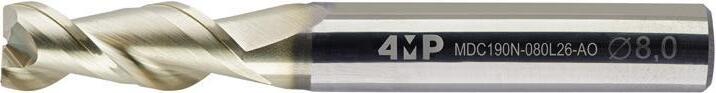


Fresa in carburo integrale
Al Z2 MDC190N
Consigliato per operazioni di contornatura e scanalatura su alluminio e non ferrosi
Alluminio solid carbide end mill Z2 MDC190N
Recommended for slot and side milling operations in Alluminio and non ferrous
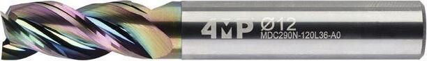


56
Fresatura integrale / Solid milling
01
C X 45° D1 D2 L2 L3 L1
Articolo Reference ØD1 h9 (mm) ØD2 h6 (mm) L1 (mm) L2 (mm) L3 (mm) D3 (mm) C (mm) Tipo attacco Shank type Z Avanzamento fz (mm/giro) Feed fz Codice Code MDC190N-040L18-A0-4MP 4 6 57 11 18 3,9 0,1 CYL 2 0,0259 71 183 777 MDC190N-050L20-A0-4MP 5 6 57 13 20 4,9 0,1 CYL 2 0,0259 71 183 785 MDC190N-060L20-A0-4MP 6 6 57 13 20 5,9 0,1 CYL 2 0,0259 71 183 793 MDC190N-080L26-A0-4MP 8 8 63 19 26 7,7 0,1 CYL 2 0,033 71 183 807 MDC190N-100L29-A0-4MP 10 10 72 22 29 9,7 0,1 CYL 2 0,0407 71 183 815 MDC190N-120L36-A0-4MP 12 12 83 26 36 11,7 0,1 CYL 2 0,0481 71 183 823 MDC190N-160L42-A0-4MP 16 16 92 32 42 15,7 0,1 CYL 2 0,0592 71 183 831 D1 D2 L2 L1 L3 Fresa in carburo integrale Al Z3 MDC290N Gole lappate Consigliato per operazioni di contornatura e scanalatura su alluminio e non ferrosi Alluminio solid carbide end mill Z3 MDC290N Polished flutes Recommended for slot and side milling operations in Alluminio and non ferrous Articolo Reference ØD1 h6 (mm) ØD2 h6 (mm) L1 (mm) L2 (mm) L3 (mm) D3 (mm) Tipo attacco Shank type Z Avanzamento fz (mm/giro) Feed fz Codice Code MDC290N-040L18-A0-4MP 4 6 57 11 18 3,9 CYL 3 0,015 - 0,025 71 183 858 MDC290N-050L20-A0-4MP 5 6 57 13 20 4,9 CYL 3 0,015 - 0,025 71 183 866 MDC290N-060L20-A0-4MP 6 6 57 13 20 5,9 CYL 3 0,025 - 0,040 71 183 874 MDC290N-080L26-A0-4MP 8 8 63 19 26 7,7 CYL 3 0,040 - 0,045 71 183 882 MDC290N-100L29-A0-4MP 10 10 72 22 29 9,7 CYL 3 0,050 - 0,065 71 183 890 MDC290N-120L36-A0-4MP 12 12 83 26 36 11,7 CYL 3 0,065 - 0,080 71 183 904 MDC290N-160L42-A0-4MP 16 16 92 32 42 15,7 CYL 3 0,090 - 0,105 71 183 912 D3 D3
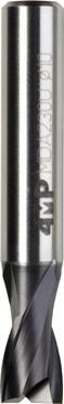
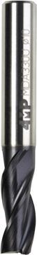


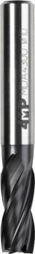
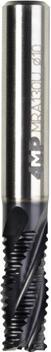
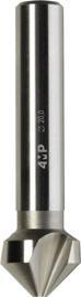
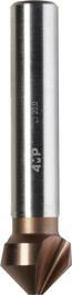


57 Fresatura integrale / Solid milling Gamma
HSSE-PM HSSE-PM end mills overview Pagina catalogo : Page catalogue P.58 P.58 P.59 P.59 P.60 P.61 P.61 Serie Series MDA230U MDA330U MDA430U MRA130U MDA530U MCA100U MCA290U Materiale Material HSSE-PM HSSE-PM HSSE-PM HSSE-PM HSSE-PM HSSE HSSE Numero di denti (Z) Nr of teeth (Z) 2 3 4 4 4 3 3 Applicazione Application Gamma Ø (mm) Ø range (mm) 2 - 20 2 - 20 2 - 20 6 - 25 6 - 20 6 - 31 6 - 31 Condizioni di taglio Cutting parameter Vc (m/mn) * Vc (m/mn) Vc (m/mn) Vc (m/mn) Vc (m/mn) Vc (m/mn) Vc (m/mn) Ap = 0,5 x D Ae = 1 x D Ap 1 x D Ae = 0,1 x D Ap 1 x D Ae = 0,1 x D Ap = 1,5 x D Ae = 0,5 x D Ap 1 x D Ae = 0,1 x D Ap = 1 x D Ae = 1 x D Ap = 2,5 x D Ae = 0,2 x D Applicazioni / Applications P Acciaio non legato Non alloyed steel O 90 - 100 O 90 - 100 O 90 - 100 O 100 - 110 O 90 - 100 O 17 - 20 O 35 - 45 Acciaio bassolegato Low alloyed steel O 60 - 70 O 60 - 70 O 60 - 70 O 90 - 100 O 60 - 70 O 10 - 15 O 20 - 30 Acciaio legato Alloyed steel O 50 - 60 O 50 - 60 O 50 - 60 O 70 - 80 O 50 - 60 O 10 - 12 O 16 - 20 M Acciaio inossidabile, duplex Duplex stainless steel O 35 - 40 O 35 - 40 O 35 - 40 O 35 - 40 O 35 - 40 O 6 - 10 O 12 - 15 Acciaio inossidabile autentico Autenetic stainless steel O 35 - 40 O 35 - 40 O 35 - 40 O 35 - 40 O 35 - 40 O 6 - 10 O 12 - 15 Acciaio inossidabile molto tenace e altamente legato Precipitation hardening stainless steel O 35 - 40 O 35 - 40 O 35 - 40 O 35 - 40 O 6 - 10 O 12 - 15 K Ghisa grigia Grey cast iron O 80 - 90 O 80 - 90 O 80 - 90 O 80 - 90 O 80 - 90 O 15 - 25 O 20 - 40 Ghisa lamellare Nodular cast iron O 60 - 70 O 80 - 90 O 80 - 90 O 80 - 90 O 80 - 90 O 15 - 25 O 20 - 40 Ghisa malleabile Malleable cast iron O 60 - 70 O 80 - 90 O 80 - 90 O 80 - 90 O 80 - 90 O 15 - 25 O 20 - 40 S Superlega a base di ferro Fer based alloy O 30 - 35 O 30 - 35 O 30 - 35 O 30 - 35 Superlega a base di cobalto Co-based alloy O 30 - 35 O 30 - 35 O 30 - 35 O 30 - 35 Superleghe a base di nichel Ni-based alloy O 30 - 35 O 30 - 35 O 30 - 35 O 30 - 35 Lega di titanio Ti-alloy O 30 - 35 O 30 - 35 O 30 - 35 O 30 - 35 N Alluminio < 9% Alluminio < 9% O 300 - 500 O 240 - 400 O 300 - 500 O 35 - 45 O 50 - 60 Lega di alluminio Aluminum alloy O 300 - 500 O 240 - 400 O 300 - 500 O 35 - 45 O 50 - 60 H Acciaio cementato, per utensili, temprato Hardened steel
delle frese
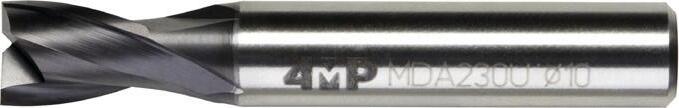


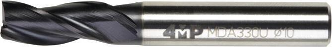


58 D1 D2 L2 L1 Fresa in HSSE-PM serie corta Z2 MDA230U Norma DIN 327K Consigliato per operazioni di scanalatura End mill HSSE-PM short Z2 MDA230U Norm DIN 327K Recommended for slot milling operations Articolo Reference ØD1 e8 (mm) ØD2 h6 (mm) L1 (mm) L2 (mm) Tipo attacco Shank type Z Avanzamento fz (mm/giro) Feed fz Codice Code MDA230U-020-W0-4MP 2 6 48 4 WLD 2 0,01 71 172 627 MDA230U-030-W0-4MP 3 6 49 5 WLD 2 0,01 71 172 635 MDA230U-040-W0-4MP 4 6 51 7 WLD 2 0,01 71 172 643 MDA230U-050-W0-4MP 5 6 52 8 WLD 2 0,01 71 172 651 MDA230U-060-W0-4MP 6 6 52 8 WLD 2 0,024 71 172 678 MDA230U-070-W0-4MP 7 10 60 10 WLD 2 0,024 71 172 686 MDA230U-080-W0-4MP 8 10 61 11 WLD 2 0,032 71 172 694 MDA230U-090-W0-4MP 9 10 61 11 WLD 2 0,032 71 172 708 MDA230U-100-W0-4MP 10 10 63 13 WLD 2 0,04 71 172 716 MDA230U-120-W0-4MP 12 12 73 16 WLD 2 0,048 71 172 724 MDA230U-140-W0-4MP 14 12 73 16 WLD 2 0,048 71 172 732 MDA230U-160-W0-4MP 16 16 79 19 WLD 2 0,064 71 172 740 MDA230U-180-W0-4MP 18 16 79 19 WLD 2 0,064 71 172 759 MDA230U-200-W0-4MP 20 20 88 22 WLD 2 0,08 71 172 767 D1 D2 L2 L1 Fresa in HSSE-PM serie corta Z3 MDA330U Norma DIN 844K Consigliato per operazioni di scanalatura e contornatura End mill HSSE-PM short Z3 MDA330U Norm DIN 844K Recommended for slot and side milling operations Articolo Reference ØD1 k10 (mm) ØD2 h6 (mm) L1 (mm) L2 (mm) Tipo attacco Shank type Z Avanzamento fz (mm/giro) Feed fz Codice Code MDA330U-020-W0-4MP 2 6 51 7 WLD 3 0,01 71 172 775 MDA330U-030-W0-4MP 3 6 52 8 WLD 3 0,01 71 172 783 MDA330U-040-W0-4MP 4 6 55 11 WLD 3 0,01 71 172 791 MDA330U-050-W0-4MP 5 6 57 13 WLD 3 0,01 71 172 805 MDA330U-060-W0-4MP 6 6 57 13 WLD 3 0,017 71 172 813 MDA330U-080-W0-4MP 8 10 69 19 WLD 3 0,023 71 172 821 MDA330U-100-W0-4MP 10 10 72 22 WLD 3 0,031 71 172 848 MDA330U-120-W0-4MP 12 12 83 26 WLD 3 0,037 71 172 856 MDA330U-160-W0-4MP 16 16 92 32 WLD 3 0,048 71 172 864 MDA330U-200-W0-4MP 20 20 104 38 WLD 3 0,063 71 172 872
integrale / Solid milling
01 Frese in acciaio HSS High speed steel end mills Fresatura
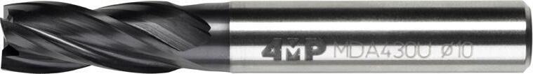


59 01
in acciaio HSS
speed steel end mills Fresatura integrale / Solid milling D1 D2 L2 L1 Fresa in HSSE-PM serie corta Z4 MDA430U
844K
End mill HSSE-PM short Z4 MDA430U Norm DIN 844K Recommended for slot and side milling operations Articolo Reference ØD1 k10 (mm) ØD2 h6 (mm) L1 (mm) L2 (mm) Tipo attacco Shank type Z Avanzamento fz (mm/giro) Feed fz Codice Code MDA430U-020-W0-4MP 2 6 51 7 WLD 4 0,01 71 172 880 MDA430U-030-W0-4MP 3 6 52 8 WLD 4 0,01 71 172 899 MDA430U-040-W0-4MP 4 6 55 11 WLD 4 0,01 71 172 902 MDA430U-050-W0-4MP 5 6 57 13 WLD 4 0,01 71 172 910 MDA430U-060-W0-4MP 6 6 57 13 WLD 4 0,017 71 172 929 MDA430U-080-W0-4MP 8 10 69 19 WLD 4 0,023 71 172 937 MDA430U-100-W0-4MP 10 10 72 22 WLD 4 0,031 71 172 945 MDA430U-120-W0-4MP 12 12 83 26 WLD 4 0,037 71 172 953 MDA430U-140-W0-4MP 14 12 83 26 WLD 4 0,037 71 172 961 MDA430U-160-W0-4MP 16 16 92 32 WLD 4 0,048 71 172 988 MDA430U-200-W0-4MP 20 20 104 38 WLD 4 0,063 71 172 996 D1 D2 L2 L1 Fresa HSSE-PM per sgrossatura Z4 MRA130U Profilo di sgrossatura Norma DIN 844K Consigliato per operazioni di scanalatura e contornatura End mill HSSE-PM roughing Z4 MRA130U Roughing profile Norm DIN 844K Recommended for slot and side milling operations Articolo Reference ØD1 k10 (mm) ØD2 h6 (mm) L1 (mm) L2 (mm) Tipo attacco Shank type Z Avanzamento fz (mm/giro) Feed fz Codice Code MRA130U-060-W0-4MP 6 6 57 13 WLD 4 0,022 71 173 011 MRA130U-080-W0-4MP 8 10 69 19 WLD 4 0,028 71 173 038 MRA130U-100-W0-4MP 10 10 72 22 WLD 4 0,039 71 173 046 MRA130U-120-W0-4MP 12 12 83 26 WLD 4 0,044 71 173 054 MRA130U-160-W0-4MP 16 16 92 32 WLD 4 0,077 71 173 062 MRA130U-200-W0-4MP 20 20 104 38 WLD 4 0,1 71 173 070 MRA130U-250-W0-4MP 25 25 121 45 WLD 5 0,11 71 173 089
Frese
High
Norma DIN
Consigliato per operazioni di scanalatura e contornatura
60 Fresatura integrale / Solid milling 01
acciaio HSS
speed steel end mills D1 D2 L2 L1 Fresa HSSE-PM serie lunga Z4 MDA530U
DIN
End mill HSSE-PM long Z4 MDA530U Norm DIN 844L Recommended for shoulder milling operations Articolo Reference ØD1 k10 (mm) ØD2 h6 (mm) L1 (mm) L2 (mm) Tipo attacco Shank type Z Avanzamento fz (mm/giro) Feed fz Codice Code MDA530U-060-W0-4MP 6 6 68 24 WLD 4 0,017 71 173 097 MDA530U-080-W0-4MP 8 10 88 38 WLD 4 0,023 71 173 100 MDA530U-100-W0-4MP 10 10 95 45 WLD 4 0,031 71 173 119 MDA530U-120-W0-4MP 12 12 110 53 WLD 4 0,037 71 173 127 MDA530U-160-W0-4MP 16 16 123 63 WLD 4 0,048 71 173 135 MDA530U-200-W0-4MP 20 20 141 75 WLD 4 0,063 71 173 143
Frese in
High
Norma
844L Consigliato per operazioni di contornatura
High speed steel end mills
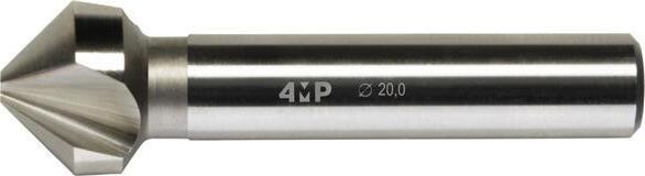

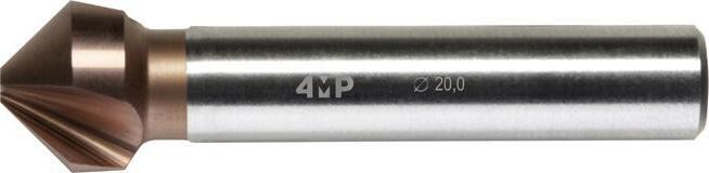

Norma DIN 335-C
Indicato per sbavatura e smussatura di parti meccaniche
Chamfering end mill HSSE MCA100U
Norm DIN 335-C
Recommended for deburring and chamfering operations on mechanical work pieces
61 01
Frese in acciaio HSS
Fresatura integrale / Solid milling D1 D2 D3 L1
HSSE MCA100U
Fresa per smussi
Articolo Reference ØD1 (mm) ØD2 (mm) L1 (mm) D3 (mm) Tipo attacco Shank type Z Codice Code MCA100U-060-AO-4MP 6,3 1,5 45 5 CYL 3 71 173 151 MCA100U-080-AO-4MP 8,3 2 50 6 CYL 3 71 173 178 MCA100U-100-AO-4MP 10,4 2,5 50 6 CYL 3 71 173 186 MCA100U-120-AO-4MP 12,4 2,8 56 8 CYL 3 71 173 194 MCA100U-160-AO-4MP 16,5 3,2 56 10 CYL 3 71 173 208 MCA100U-200-AO-4MP 20,5 3,5 63 10 CYL 3 71 173 216 MCA100U-250-AO-4MP 25 3,8 67 10 CYL 3 71 173 224 MCA100U-310-AO-4MP 31 4,2 71 12 CYL 3 71 173 232 SET6-MCA100U-4MP Scatole da 6 frese / Set of 6 mills : 6,3 - 8,3 - 10,4 - 12,4 - 16,5 - 20,5 71 178 730 D3 L1 D1 D2 Fresa per smussi HSSE-CO MCA290U Fresa per smussi antivibrazioni 3 denti a 90° Rivestita TIALN Norma DIN 335-C Indicato per sbavatura e smussatura di parti meccaniche Chamfering end mill HSSE-CO MCA290U Chamfering end mill 3 flutes antivibrations 90° TIALN coating DIN 335-C Recommended for deburring and chamfering operations on mechanical work pieces. Articolo Reference ØD1 (mm) ØD2 (mm) L1 (mm) D3 (mm) Tipo attacco Shank type Z Codice Code MCA290U-060-AO-4MP 6,3 1,5 45 5 CYL 3 71 173 240 MCA290U-080-AO-4MP 8,3 2 50 6 CYL 3 71 173 259 MCA290U-100-AO-4MP 10,4 2,5 50 6 CYL 3 71 173 267 MCA290U-120-AO-4MP 12,4 2,8 56 8 CYL 3 71 173 275 MCA290U-160-AO-4MP 16,5 3,2 56 10 CYL 3 71 173 283 MCA290U-200-AO-4MP 20,5 3,5 63 10 CYL 3 71 173 291 MCA290U-250-AO-4MP 25 3,8 67 10 CYL 3 71 173 305 MCA290U-310-AO-4MP 31 4,2 71 12 CYL 3 71 173 313
62 Codifica Designation
R 1 U 6 A 2 1 3 0 4 0 5 30 7 - - A 8 1 9 Alesatore Reamer 1 U - Universale U – Un � verselle P - Acciaio P - Steel K - Ghisa K - Cast � ron M - Acciaio inossidabile M - Sta � nless steel S - Superlega S - H � gh temperature alloy H - Acciaio duro H - Hard steel N - Alluminio N - Alum � num C – Composito C - Compos � te Appl�caz�one Appl�cat�on 7 C – Carburo C - Carb � de A - Acciaio A - Steel Mater�ale Mater�al 2 030 - 3,0 mm D�ametro DC DC d�ameter 8 1º gamma 1 - 1 st range 2º gamma 2 - 2 nd range Gamma Range 3 A - Cilindrico A - Cyl � ndr � cal C - Cono morse C - Morse tapper Attacco Shank 8 0 - Non rivestito 0 - Uncoated 1 - VAP 2 - TIN 3 - ALTIN 4 - TICN 5 - TIALN 9 - SPECIALE 9 - Specıal R�vest�mento Coat�ng 5 1 - Interno 1 - Internal 0 - Esterno 0 - External Lubr�f�caz�one Coolant 9 Generaz�one Generat�on 5 Alesatura integrale / Solid reaming
system GAMMA DEGLI ALESATORI OVERVIEW OF REAMERS


Overview of reamers

63
Gamma degli alesatori
Pagina catalogo : Page catalogue : P.64 P. 64 P.65 P.66 Serie Series RC400U RA100U RA200U RA300U Tipo Type Alesatore a macchina Machine reamer Alesatore a macchina Machine reamer Alesatore a macchina Machine reamer Alesatore manuale Hand reamer Materiale Material CW HSSE HSSE HSS Applicazione Application Gamma Ø (mm) Ø range (mm) 1 - 12 3 - 20 16 - 30 3 - 30 Condizioni di taglio Cutting parameter Vc (m/mn) Vc (m/mn) Vc (m/mn) Vc (m/mn) Applicazioni Applications P Acciaio non legato Non alloyed steel O 15 - 20 O 8 - 12 O 8 - 12 O 8 - 12 Acciaio bassolegato Low alloyed steel O 12 - 15 O 8 - 12 O 8 - 12 O 8 - 12 Acciaio legato Alloyed steel O 10 - 12 O 6 - 10 O 6 - 10 O 6 - 10 M Acciaio inossidabile, duplex Duplex stainless steel O 7 - 10 O 6 - 10 O 6 - 10 O 6 - 10 Acciaio inossidabile autentico Autenetic stainless steel O 7 - 10 O 6 - 10 O 6 - 10 O 6 - 10 Acciaio inossidabile molto tenace e altamente legato Precipitation hardening stainless steel O 7 - 10 O 6 - 10 O 6 - 10 O 6 - 10 K Ghisa grigia Grey cast iron O 15 - 20 O 8 - 15 O 8 - 15 O 8 - 15 Ghisa lamellare Nodular cast iron O 15 - 20 O 6 - 12 O 6 - 12 O 6 - 12 Ghisa malleabile Malleable cast iron O 15 - 20 O 6 - 12 O 6 - 12 O 6 - 12 S Superlega a base di ferro Fer based alloy Superlega a base di cobalto Co-based alloy Superleghe a base di nichel Ni-based alloy Lega di titanio Ti-alloy N Alluminio < 9% Aluminium < 9% O 40 - 50 O 15 - 25 O 15 - 25 O 15 - 25 Lega di alluminio Aluminum alloy O 40 - 50 O 20 - 30 O 20 - 30 O 20 - 30 H Acciaio cementato, per utensili, temprato Hardened steel Alesatura integrale / Solid reaming
64
01
Alesatura integrale / Solid reaming D1 D2 L2 L3 L1
a macchina integrale RC400U Elica a 7° Elica sinistra taglio destro Tolleranza H7
cilindrico DIN 6535
Angle
7° Left hand spiral
Tolerance H7 Cylindrical shank DIN
Articolo Reference ØD1 H7 (mm) ØD2 (mm) L1 (mm) L2 (mm) L3 (mm) Tipo attacco Shank type Z Codice Code RC400U-010-A0-4MP 1 4 35 10 17 CYL 4 71 173 712 RC400U-020-A0-4MP 2 4 50 18 31 CYL 4 71 173 720 RC400U-025-A0-4MP 2,5 4 55 20 34 CYL 4 71 173 739 RC400U-030-A0-4MP 3 4 60 20 39 CYL 4 71 173 747 RC400U-035-A0-4MP 3,5 4 60 22 37 CYL 4 71 173 755 RC400U-040-A0-4MP 4 4 65 24 40 CYL 4 71 173 763 RC400U-045-A0-4MP 4,5 6 65 24 40 CYL 6 71 173 771 RC400U-050-A0-4MP 5 6 75 26 48 CYL 6 71 173 798 RC400U-055-A0-4MP 5,5 6 75 26 48 CYL 6 71 173 801 RC400U-060-A0-4MP 6 6 75 26 48 CYL 6 71 173 828 RC400U-065-A0-4MP 6,5 8 80 30 49 CYL 6 71 173 836 RC400U-070-A0-4MP 7 8 80 35 59 CYL 6 71 173 844 RC400U-080-A0-4MP 8 8 100 35 64 CYL 6 71 173 852 RC400U-090-A0-4MP 9 10 100 35 64 CYL 6 71 173 860 RC400U-100-A0-4MP 10 10 100 35 64 CYL 6 71 173 879 RC400U-120-A0-4MP 12 12 100 35 64 CYL 6 71 173 887 D1 D2 L2 L1 L3 Alesatore a macchina HSSE RA100U Elica a 10° Elica sinistra taglio destro Tolleranza H7 Norma DIN 212-B Machine reamers HSSE RA100U Angle helix 10° Left hand spiral right hand cut Tolerance H7 DIN 212-B Articolo Reference ØD1 H7 (mm) ØD2 h9 (mm) L1 (mm) L2 (mm) L3 (mm) Tipo attacco Shank type Z Codice Code RA100U-030-A0-4MP 3 3 61 15 - CYL 6 71 173 321 RA100U-035-A0-4MP 3,5 3,5 70 18 - CYL 6 71 173 348 RA100U-040-A0-4MP 4 4 75 19 56 CYL 6 71 173 356 RA100U-045-A0-4MP 4,5 4,5 80 21 43 CYL 6 71 173 364 RA100U-050-A0-4MP 5 5 86 23 47 CYL 6 71 173 372 RA100U-055-A0-4MP 5,5 5,6 93 26 57 CYL 6 71 173 380 RA100U-060-A0-4MP 6 5,6 93 26 57 CYL 6 71 173 399 RA100U-065-A0-4MP 6,5 6,3 101 28 63 CYL 6 71 173 402 RA100U-070-A0-4MP 7 7,1 109 31 69 CYL 6 71 173 410 RA100U-080-A0-4MP 8 8 117 33 75 CYL 6 71 173 429
Alesatori a macchina Machine reamers
Alesatore
Gambo
Solid carbide machine reamers RC400U
helix
right hand cut
6535
65 01 Alesatura integrale / Solid reaming
D1 D2 L2 L1 L3 Alesatore a macchina HSSE RA100U Elica a 10° Elica sinistra taglio destro Tolleranza H7 Norma DIN 212-B Machine reamers HSSE RA100U Angle helix 10° Left hand spiral right hand cut Tolerance H7 DIN 212-B Articolo Reference ØD1 H7 (mm) ØD2 h9 (mm) L1 (mm) L2 (mm) L3 (mm) Tipo attacco Shank type Z Codice Code RA100U-090-A0-4MP 9 9 125 36 81 CYL 6 71 173 437 RA100U-100-A0-4MP 10 10 133 38 87 CYL 6 71 173 445 RA100U-110-A0-4MP 11 10 142 41 96 CYL 8 71 173 453 RA100U-120-A0-4MP 12 10 151 44 105 CYL 8 71 173 461 RA100U-130-A0-4MP 13 10 151 44 105 CYL 8 71 173 488 RA100U-140-A0-4MP 14 12,5 160 47 110 CYL 8 71 173 496 RA100U-150-A0-4MP 15 12,5 162 50 112 CYL 8 71 173 518 RA100U-160-A0-4MP 16 12,5 170 52 120 CYL 8 71 173 526 RA100U-180-A0-4MP 18 14 182 56 130 CYL 8 71 173 534 RA100U-200-A0-4MP 20 16 195 60 137 CYL 10 71 173 542 D1 D2 L2 L3 L1 Alesatore a macchina HSSE CM RA200U Elica a 10° Elica sinistra taglio destro Tolleranza H7 Norma DIN 208-B Machine reamers HSSE CM RA200U Angle helix 10° Left hand spiral right hand cut Tolerance H7 DIN 208-B Articolo Reference ØD1 H7 (mm)Tipo attaccoment Shank type L1 (mm) L2 (mm) L3 (mm) Z Codice Code RA200U-160-C0-4MP 16 CM2 210 52 130 8 71 173 550 RA200U-170-C0-4MP 17 CM2 214 54 134 8 71 173 569 RA200U-180-C0-4MP 18 CM2 219 56 139 8 71 173 577 RA200U-190-C0-4MP 19 CM2 223 58 143 10 71 173 585 RA200U-200-C0-4MP 20 CM2 228 60 148 10 71 173 593 RA200U-210-C0-4MP 21 CM2 232 62 152 10 71 173 607 RA200U-220-C0-4MP 22 CM2 237 64 157 10 71 173 615 RA200U-230-C0-4MP 23 CM3 241 66 161 10 71 173 623 RA200U-240-C0-4MP 24 CM3 268 68 169 10 71 173 631 RA200U-250-C0-4MP 25 CM3 268 68 169 10 71 173 658 RA200U-260-C0-4MP 26 CM3 273 70 174 10 71 173 666 RA200U-270-C0-4MP 27 CM3 277 71 178 10 71 173 674 RA200U-280-C0-4MP 28 CM3 277 71 178 10 71 173 682 RA200U-290-C0-4MP 29 CM3 281 71 182 10 71 173 690 RA200U-300-C0-4MP 30 CM3 281 73 182 10 71 173 704
Alesatori a macchina Machine reamers
66 01 Alesatura integrale / Solid reaming Alesatori manuali Hand reamers D1 D2 L2 L3 L1 Alesatore manuale HSS RA300U Elica a 7° Elica sinistra taglio destro Tolleranza H7 Norma DIN 206-B Hand reamers HSS RA300U Angle helix 7° Left hand spiral right hand cut Tolerance H7 DIN 206-B Articolo Reference ØD1 H7 (mm)ØD2 e9 (mm) L1 (mm) L2 (mm) L3 (mm) Z Codice Code RA300U-030-A0-4MP 3 3 62 31 31 6 71 173 895 RA300U-040-A0-4MP 4 4 76 38 48 6 71 173 909 RA300U-050-A0-4MP 5 5 87 44 55 6 71 173 917 RA300U-060-A0-4MP 6 6 83 47 61 6 71 173 925 RA300U-070-A0-4MP 7 7 107 54 68 6 71 173 933 RA300U-080-A0-4MP 8 8 115 58 78 6 71 173 941 RA300U-090-A0-4MP 9 9 124 62 82 6 71 173 968 RA300U-100-A0-4MP 10 10 133 66 86 6 71 173 976 RA300U-110-A0-4MP 11 11 142 71 91 8 71 173 984 RA300U-120-A0-4MP 12 12 152 76 96 8 71 173 992 RA300U-130-A0-4MP 13 13 152 76 96 8 71 174 018 RA300U-140-A0-4MP 14 14 163 81 105 8 71 174 026 RA300U-150-A0-4MP 15 15 163 81 105 8 71 174 034 RA300U-160-A0-4MP 16 16 175 87 115 8 71 174 042 RA300U-180-A0-4MP 18 18 188 93 121 8 71 174 050 RA300U-200-A0-4MP 20 20 201 100 127 10 71 174 069 RA300U-210-A0-4MP 21 21 201 100 127 10 71 174 077 RA300U-220-A0-4MP 22 22 215 107 137 10 71 174 085 RA300U-240-A0-4MP 24 24 231 115 145 10 71 174 093 RA300U-250-A0-4MP 25 25 231 115 145 10 71 174 107 RA300U-260-A0-4MP 26 26 231 115 159 10 71 174 115 RA300U-280-A0-4MP 28 28 247 124 159 10 71 174 123 RA300U-300-A0-4MP 30 30 247 124 159 10 71 174 131

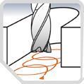


Attacco / Shank type
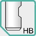
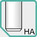
Weldon C � l � ndr � co / Cyl � ndr � cal
Angolo dell’el�ca / Po�nt angle
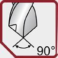
Numero d� dent� / Teeth number
Angolo dell’el�ca / Hel�x angle
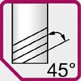
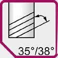
Forma della fresa
M�ll t�p form
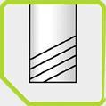

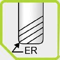
Sp � golo aff � lato / Sharp corner
Sp � golo smussato 45° / Corner protect � on 45° Ragg � o / Corner rad � us
Ragg�o completo / Ball nose
Lubr�f�caz�one Coolant type


Esterno / External Interno / Internal coolant
type
Metr � co / Metr � c Metr � co f � ne / F � ne metr � c GAZ GAS UNC
Profond�tà d� masch�atura Tapp�ng depth
Imbocco Chamfer form
Forma B, 4-5 passo / form B, 4-5 threads
Forma C, 2-3 passo / form C, 2-3 threads
67
Appl�caz�one
Fresatura
�
� ll � ng F � n � tura / F � n � sh � ng Fresatura
� nam � ca / Dynam � c m � ll � ng Prof � latura / Prof � l � ng Mater�al�
Acc � a � o � noss � dab � le / sta � nless steel Allum � n � o e non ferros � / Alum � num and non ferrous Acc � a � o / Steel Un � versale / Un � versal Forma gole Flutes type Gole dr � tte / stra � ght flutes Gole el � co � dal � / Hel � cal flutes A rullatura / Form � ng Classe d� tolleranza Tolerance class G 2B T�po d� masch�atura Tapp�ng
Frese e punte End mills and drills Maschi Taps DESCRIZIONE PITTOGRAMMI ICONS DESCRIPTION
Appl�cat�on
d � spallament � / Shoulder m � ll
ng Scanalatura / Slot m
d
Mater�als
2.5
CI SONO NUOVE SOLUZIONI
La produzione richiede numerosi cambi di utensili e operazioni di rilavorazione: la velocità e l’accuratezza della scelta sono fondamentali per garantire le prestazioni. Gli operatori richiedono utensili da taglio estremamente precisi, fabbricati nel più breve tempo possibile e a costi controllati.
Noi vi aiutiamo a progettare e implementare nuovi utensili per soddisfare tutte le vostre esigenze, produrre forme speciali adatte al materiale da lavorare e alle condizioni di taglio.
YOU HAVE NEW SOLUTIONS
Manufacturing requires many tools changes, or machining rework : speed and accuracy of choices are essential to ensure performance. The Machininists require extremely precise cutting tools, manufactured as soon as possible at reasonable cost.
We help you to design and implement new tools to meet all your requirements, to produce specific forms, to adapt to the material and cutting parameters.
PRODUZIONE SU MISURA CUSTOM

TEMPESTIVITÀ
Tempestività ottimale da parte dei nostri reparti di a�latura e produzione
COMPETITIVITÀ
Attrezzature ad alta tecnologia che vengono regolarmente ottimizzate grazie a continui investimenti
COMPETENZA
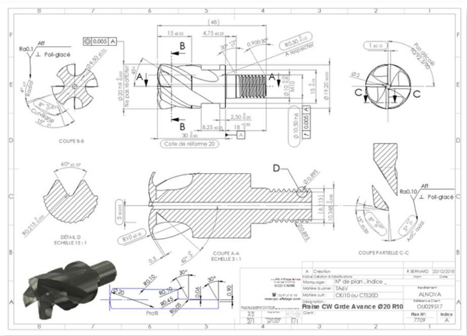
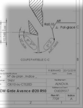


Quasi cinquanta tecnici esperti e qualificati al vostro servizio
QUALITÀ
Certificazione ISO 9001 versione 2015
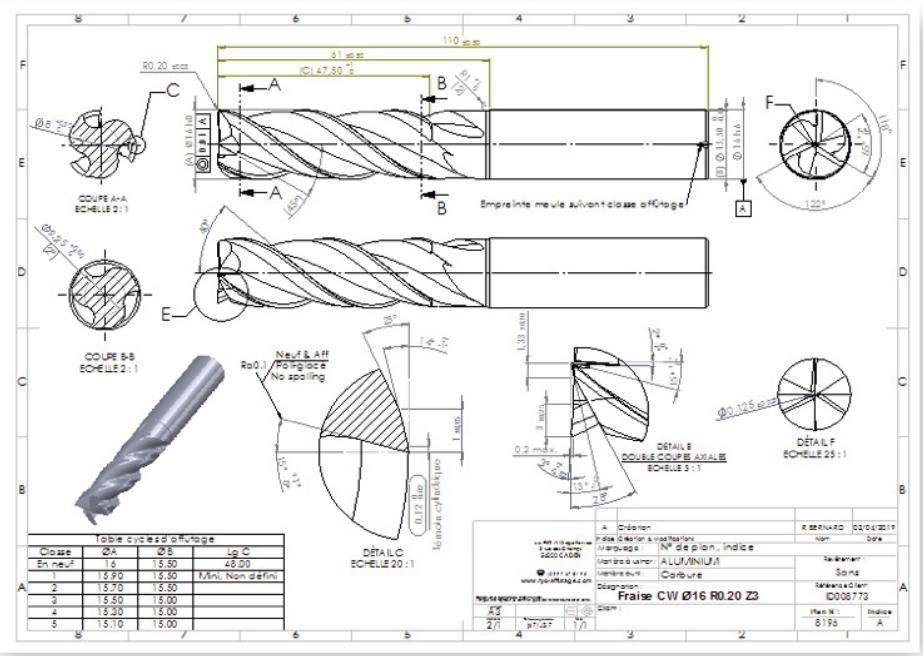


RESPONSIVENESS
An optimal responsiveness from our services
COMPETITIVENESS
A high quality equipment, optimized on a regular basis thanks to continous investments
TECHNICITY
Fifty highly skilled and experienced technicians at your disposal
REALIZZAZIONE UTENSILI DA TAGLIO SPECIALI SU DISEGNO PRODUCTION OF SPECIAL CUTTING TOOLS
ISO 9001 certification (2015)
QUALITY
40 000 UTENSILI DA TAGLIO SPECIALI PRODOTTI OGNI ANNO di + + OF 40 000 SPECIAL CUTTING TOOLS MANUFACTURED EACH YEAR 68
MANUFACTURING
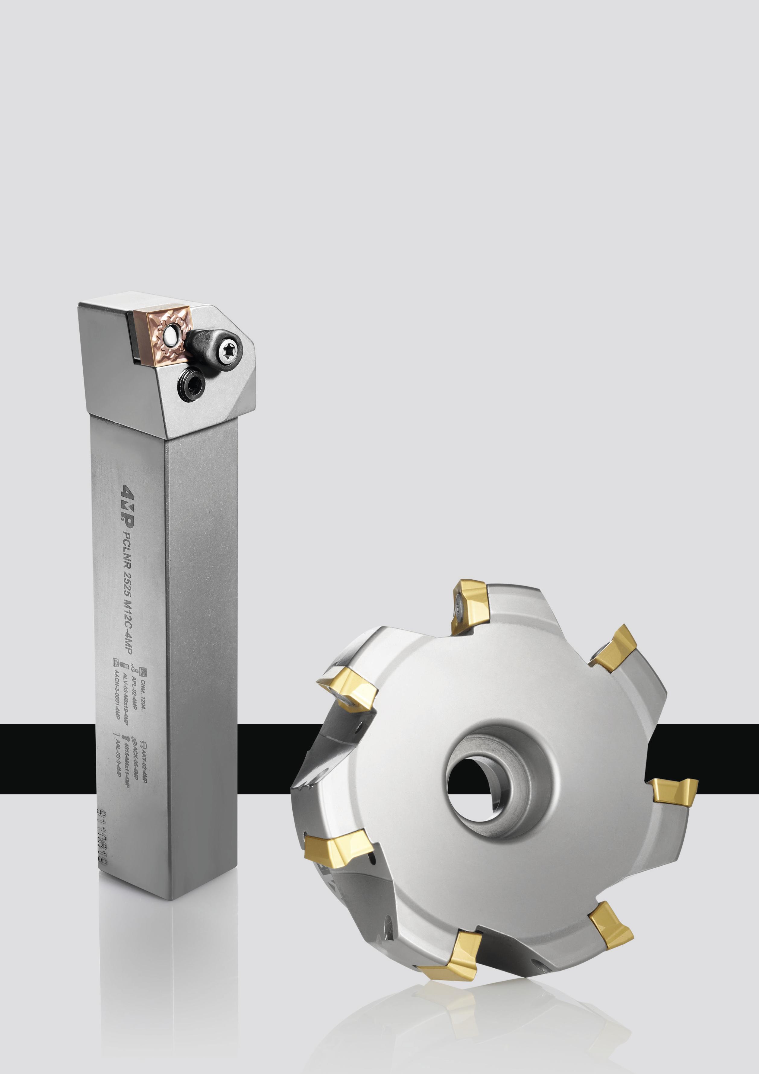
02 Inserti e portainserti Inserts & Toolholders 69
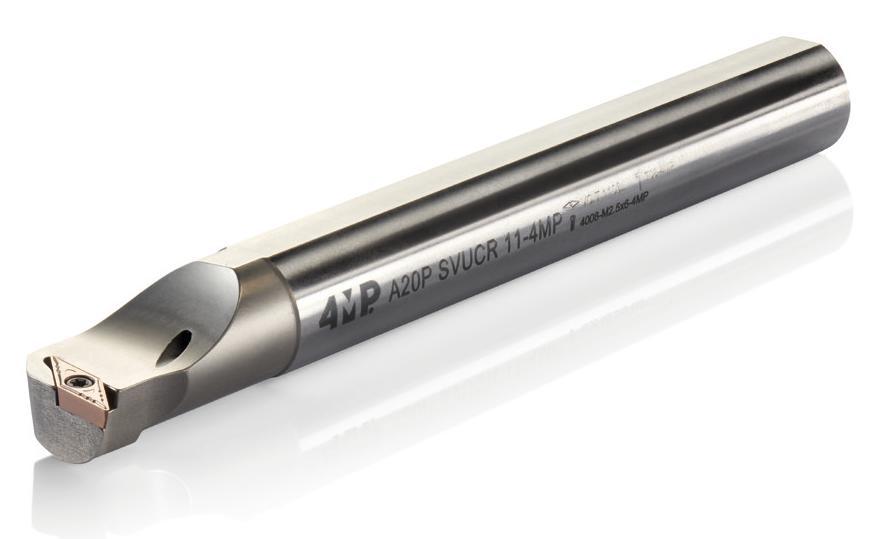
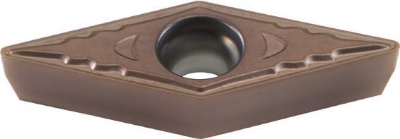
Tornitura / Turning
TURNING 02 Porta-inserti di tornitura ISO Turning ISO toolholders Tornitura esterna 72 Codifica 73 Porta-inserti esterni per inserti negativi 77 Porta-inserti esterni per inserti positivi Tornitura interna 78 Codifica 79 Porta-inserti interni per inserti negativi 81 Porta-inserti interni per inserti positivi External turning Designation system External toolholders for negative inserts External toolholders for positive inserts Internal turning Designation system Internal toolholders for negative inserts Internal toolholders for positive inserts Accessories Tables of equivalences toolholders / accessories 83 Accessori 86 Tabelle di corrispondenze portautensili/accessori Designation system Chip breaker selector Negative inserts Positive inserts Grade description Cutting parameters Negative inserts Positive inserts 90 Codifica Scelta dei rompitrucioli 91 Inserti negativi 95 Inserti positivi 98 Descrizione dei gradi 99 Parametri velocità di taglio 100 Inserti negativi 105 Inserti positivi Inserti di tornitura ISO Turning ISO inserts Normal failures & solutions Grade conversion table 110 Criticità classiche classici e soluzioni 111 Tabella delle equivalenze dei gradi Tornitura Turning Informazioni tecniche 71 Technical information 70
TORNITURA
Veloc�tà d� tagl�o e rotaz�one
Cutt�ng speed
1000 * Vc
n = (tr/m�n)
* Dc
* Dc * n
Vc = (m/m�n)
1000
Vc : Veloc�tà d� tagl�o / Cutt�ng speed (m/m�n)
: 5 3.14
Dc : D�ametro / D�ameter (mm)
n : Veloc�tà d� rotaz�one / Sp�ndle speed (tr/m�n)
Vf = f * n (mm/m�n)
Avanzamento
Feed speed
Vf
f = n (mm/m�n)
Vf : Avanzamento / Feed rate (mm/m�n)
f : Avanzamento per g�ro / Feed rate per turn (mm/rev)
n : Veloc�tà d� rotaz�one / Sp�ndle speed (rev/m�n)
Tempo d� lavoraz�one Mach�n�ng t�me
L
Tc = (m�n) f * n
Tc : Tempo d� lavoraz�one / Mach�n�ng t�me
f : Avanzamento / Feed rate (mm/rev)
n : Veloc�tà d� rotaz�one / Sp�ndle speed (rev/m�n)
L : Percorso d� lavoraz�one / Work�ng length (mm)
Rugos�tà
Theoret�c surface roughness
f2
Rmax = * 1000 (um)
8 * r
Rmax : Rugos�tà / Theoret�c surface roughness (um)
f : Avanzamento / Feed rate(mm/rev)
r : Ragg�o d� �nsert� / Corner rad�us (mm)
Volume truc�olo
Ch�p removal
Q = ap * f * Vc (cm3/m�n)
Q : Volume truc�olo / Ch�p removal (cm�/m�n)
ap : Profond�tà d� tagl�o / Ax�al depth of cut (mm)
f : Avanzamento / Feed rate (mm/rev)
Vc : Veloc�tà d� tagl�o / Cutt�ng speed (m/m�n)
Tornitura / Turning
tecniche
Rmax f r L
Informazioni
Technical information TORNITURA TURNING
n 71
ø Dc
F�ssagg�o super�ore con foro Top and Hole Clamp � ng
F�ssagg�o super�ore con foro + Sta�a Top and Hole Clamp � ng
Inserto con foro F�ssagg�o sta�a + Leva Hole Clamp � ng (Lever Lock)
Inserto con foro Serragg�o v�te Screw on
72 Tornitura / Turning P 1 C 2 L 3 N 4 R 5 Lunghezza
Cutt�ng edge length Larghezza del corpo Shank w�dth Altezza del corpo Shank he�ght
clamp Forma dell’�nserto Insert shape 2 C D E K L R S T V W A B H M O P D�rez�one d� tagl�o Cutt�ng d�rect�on L N R A.B.K H C.D.E M.V L O P R S T W Lunghezza totale Tool length L S T V Y Z O J K L M N R A B D E F G Forma dell’utens�le Tool type 90° 93° 45° 60° 72.5° 85° 40° 75° 50° 63° 75° 95° 95° 75° 45° 60° 90° 90° 3 Angolo d� spogl�a �nserto Insert clearance angle G N P D E F A B C 3° 5° 7° 15° 20° 25° 30° 0° 11° 4 5 6 7 8 9 10 A-32 H-100 Q-180
B-40 J-110 R-200
25 6 25 7 M 8 12 9 C 10
del tagl�ente �nserto
Spec�f�c�tà Wedge
X speciale X-spec�al
C-50 K-125 S-250 D-60 L-140 T-300 E-70 M-150 U-350 F-80 N-160 V-400 G-90 P-170 W-450 (mm)
Codifica Designation system
F�ssagg�o super�ore senza foro Top Clamp � ng W � thout Hole
T M
S
C
P
Metodo d� f�ssagg�o dell’�nserto Clamp�ng system 1 PORTA-INSERTI DI TORNITURA ISO ESTERNO EXTERNAL TURNING TOOLHOLDERS
Tornitura, porta-inserti esterni per inserti negativi
Turning, external toolholders for negative inserts
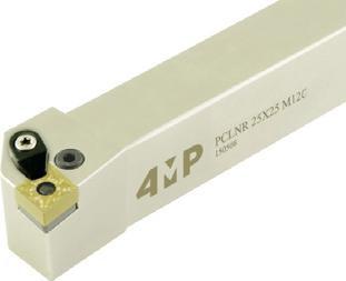
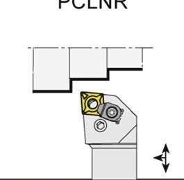
Portautensili tornitura esterna PCLNR/L
Utensile di tornitura esterna a sta a per inserti negativi CN… Articolo
* Attenzione: Questi portautensili non sono dotati di sta�a / Beware : toolholders without clamp
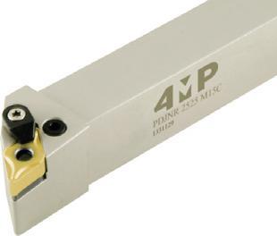
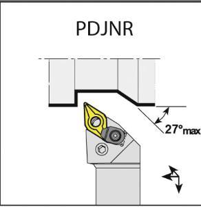
* Attenzione: Questi portautensili non sono dotati di sta�a / Beware : toolholders without clamp
02 Tornitura / Turning 73
Reference
Larghezza
Shank width (mm) Altezza
Shank height (mm)
(mm)
cutting edge / rear face (mm)
(mm) Total length (mm) Tipo di inserto Suitable insert Codice Code PCLNR 1616 H12-4MP* destra / right 16 16 20 100 CN..1204 65 253 291 PCLNR 2020 K12C-4MP destra / right 20 20 25 125 CN..1204 65 253 313 PCLNR 2525 M12C-4MP destra / right 25 25 32 150 CN..1204 65 253 348 PCLNR 3232 P12C-4MP destra / right 32 32 40 170 CN..1204 65 253 364 PCLNL 1616 H12-4MP* sinistra / left 16 16 20 100 CN..1204 65 253 305 PCLNL 2020 K12C-4MP sinistra / left 20 20 25 125 CN..1204 65 253 321 PCLNL 2525 M12C-4MP sinistra / left 25 25 32 150 CN..1204 65 253 356 PCLNL 3232 P12C-4MP sinistra / left 32 32 40 170 CN..1204 65 253 372 External turning toolholder PCLNR/L External turning tool with clamping flange for negative inserts CN… Portautensili tornitura esterna PDJNR/L Utensile di tornitura esterna a sta a per inserti negativi DN… Articolo Reference Direzione dell’utensile R/L Hand Larghezza attacco (mm) Shank width (mm) Altezza attacco (mm) Shank height (mm) Distanza punta lato posteriore (mm) Distance cutting edge / rear face (mm) Lunghezza totale (mm) Total length (mm) Tipo di inserto Suitable insert Codice Code PDJNR 1616 H11-4MP* destra / right 16 16 20 100 DN..1104 65 253 380 PDJNR 2020 K11-4MP* destra / right 20 20 25 125 DN..1104 65 253 402 PDJNR 2020 K15C-4MP destra / right 20 20 25 125 DN..1506 65 253 429 PDJNR 2525 M11-4MP destra / right 25 25 32 150 DN..1104 65 253 445 PDJNR 2525 K15C-4MP destra / right 25 25 32 150 DN..1506 65 253 461 PDJNL 1616 H11-4MP* sinistra / left 16 16 20 100 DN..1104 65 253 399 PDJNL 2020 K15C-4MP sinistra / left 20 20 25 125 DN..1506 65 253 437 PDJNL 2020 K11-4MP* sinistra / left 20 20 25 125 DN..1104 65 253 410 PDJNL 2525 M11-4MP sinistra / left 25 25 32 150 DN..1104 65 253 453 PDJNL 2525K 15C-4MP sinistra / left 25 25 32 150 DN..1506 65 253 488 External turning toolholder PDJNR/L External
PCLNR PDJNR
Direzione dell’utensile R/L Hand
attacco (mm)
attacco (mm)
Distanza punta lato posteriore
Distance
Lunghezza totale
turning tool with clamping flange for negative inserts DN…
Tornitura, porta-inserti esterni per inserti negativi
Turning, external toolholders for negative inserts
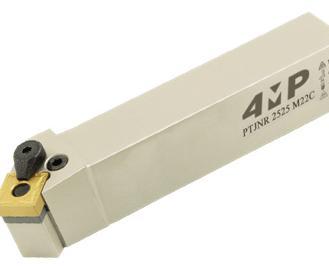
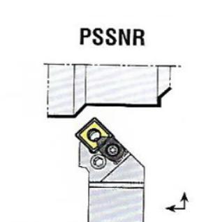
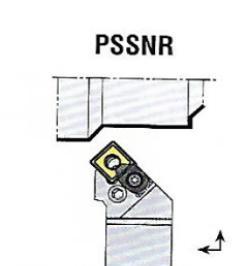
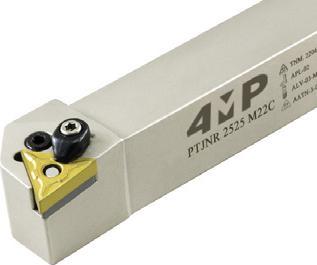
Portautensili tornitura esterna PTJNR/L Utensile di tornitura esterna a sta a per inserti negativi TN…
* Attenzione: Questi portautensili non sono dotati di sta�a / Beware : toolholders without clamp
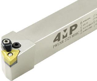
* Attenzione: Questi portautensili non sono dotati di sta�a / Beware : toolholders without clamp PWL
Utensile di tornitura esterna a sta a per inserti negativi TN…
External turning toolholder PWLNR/L
External turning tool with clamping flange for negative inserts WN…
02 74 Tornitura / Turning
tornitura esterna
inserti
Articolo Reference Direzione dell’utensile R/L Hand Larghezza attacco (mm) Shank width (mm) Altezza attacco (mm) Shank height (mm) Distanza punta lato posteriore (mm) Distance cutting edge / rear face (mm) Lunghezza totale (mm) Total length (mm) Tipo di inserto Suitable insert Codice Code PSSNR 2020 K12C-4MP destra / right 20 20 25 125 SNM..1204 67 467 469 PSSNR 2525 M12C-4MP destra / right 25 25 32 150 SNM..1204 67 467 477 PSSNR 3232 P12C-4MP destra / right 32 32 40 170 SNM..1204 67 467 485 PSSNL 2020 K12C-4MP sinistra / left 20 20 25 125 SNM..1204 67 467 426 PSSNL 2525 M12C-4MP sinistra / left 25 25 32 150 SNM..1204 67 467 434 PSSNL 3232 P12C-4MP sinistra / left 32 32 40 170 SNM..1204 67 467 442
Portautensili tornitura esterna PSSNR/L Utensili di
per
negativi SNM…
External turning toolholder PSSNR/L External turning tool for negative inserts SNM…
Articolo Reference Direzione dell’utensile R/L Hand Larghezza attacco (mm) Shank width (mm) Altezza attacco (mm) Shank h eight (mm) Distanza
PTJNR 2020 K16-4MP* destra / right 20 20 25 125 TN..1604 65 253 496 PTJNR 2525 M16-4MP* destra / right 25 25 32 150 TN..1604 65 253 526 PTJNL 2020 K16-4MP* sinistra / left 20 20 25 125 TN..1604 65 253 518 PTJNL 2525 M16-4MP* sinistra / left 25 25 32 150 TN..1604 65 253 534
PTJNR/L
flange
TN…
punta lato posteriore (mm) Distance cutting edge / rear face (mm) Lunghezza totale (mm) Total length (mm) Tipo di inserto Suitable insert Codice Code
External turning toolholder
External turning tool with clamping
for negative inserts
Portautensili tornitura esterna PTJNR/L
Articolo Reference Direzione dell’utensile R/L Hand Larghezza attacco (mm) Shank width (mm) Altezza attacco (mm) Shank height (mm) Distanza punta lato posteriore (mm) Distance cutting edge / rear face (mm) Lunghezza totale (mm) Total length (mm) Tipo di inserto Suitable insert Codice Code PWLNR 1616 H06-4MP* destra / right 16 16 20 100 WN..0604 65 253 542 PWLNR 2020 K08C-4MP destra / right 20 20 25 125 WN..0804 65 253 585 PWLNR 2020 K06-4MP* destra / right 20 20 25 125 WN..0604 65 253 569 PWLNR 2525 K08C-4MP destra / right 25 25 32 150 WN..0804 65 253 623 PWLNL 1616 H06-4MP* sinistra / left 16 16 20 100 WN..0604 65 253 550 PWLNL 2020 K08C-4MP sinistra / left 20 20 25 125 WN..0804 65 253 593 PWLNL 2020 K06-4MP* sinistra / left 20 20 25 125 WN..0604 65 253 577 PWLNL 2525 K08C-4MP sinistra / left 25 25 32 150 WN..0804 65 253 631
PTJNR
PSSNR
Tornitura, porta-inserti esterni per inserti negativi
Turning, external toolholders for negative inserts
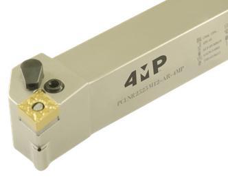
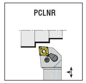
Portautensili tornitura esterna PCLNR/L
Refrigerazione integrata
Refrigerazione interna. Utensile di tornitura esterna per inserti negativi NC…
Pressione di refrigerazione: da 10 bar a 275 bar.
External turning toolholder PCLNR/L Internal coolant. External turning tool for negative inserts CN… Coolant pressure : 10 bar to max 275 bar.
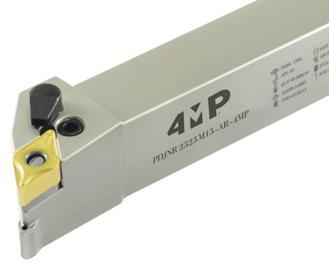
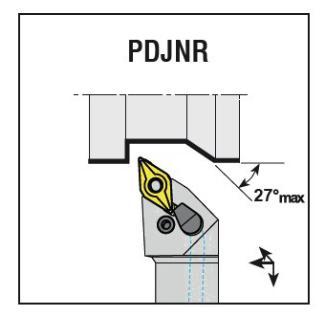
integrata Refrigerazione interna. Utensile di tornitura esterna per inserti negativi DN… Pressione di refrigerazione: da 10 bar a 275 bar. External turning toolholder
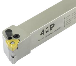
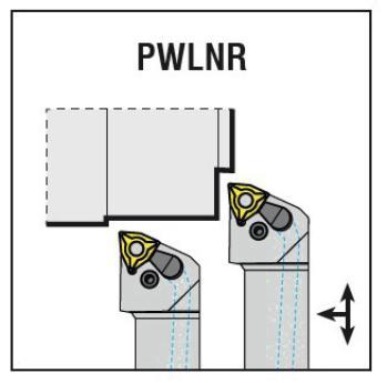
Portautensili tornitura esterna PWLNR/L Refrigerazione integrata Refrigerazione interna. Utensile di tornitura esterna per inserti negativi WN… Pressione di refrigerazione: da 10 bar a 275 bar.
External turning toolholder
02 75 Tornitura / Turning
Reference Direzione dell’utensile R/L Hand Larghezza attacco (mm) Shank width (mm)
Shank height (mm)
(mm)
(mm) Total length (mm) Tipo di inserto Suitable insert Codice Code PCLNR 2020 K12-AR-4MP destra / right 20 20 25 125 CN..1204 69 109 063 PCLNR 2525 M12-AR-4MP destra / right 25 25 32 150 CN..1204 69 109 071 PCLNL 2020 K12-AR-4MP sinistra / left 20 20 25 125 CN..1204 69 109 047 PCLNL 2525 M12-AR-4MP sinistra / left 25 25 32 150 CN..1204 69 109 055 Portautensili tornitura esterna PDJNR/L Refrigerazione
for negative inserts DN… Coolant pressure : 10 bar to max 275 bar. Articolo Reference Direzione dell’utensile R/L Hand Larghezza attacco (mm) Shank width (mm) Altezza attacco (mm) Shank height (mm) Distanza punta lato posteriore (mm) Distance cutting edge / rear face (mm) Lunghezza totale (mm) Total length (mm) Tipo di inserto Suitable insert Codice Code PDJNR 2020 K15-AR-4MP destra / right 20 20 25 125 DN..1506 69 109 128 PDJNR 2525 M15-AR-4MP destra / right 25 25 32 150 DN..1506 69 109 136 PDJNL 2020 K15-AR-4MP sinistra / left 20 20 25 125 DN..1506 69 109 098 PDJNL 2525 M15-AR-4MP sinistra / left 25 25 32 150 DN..1506 69 109 101
Articolo
Altezza attacco (mm)
Distanza punta lato posteriore
Distance cutting edge / rear face (mm) Lunghezza totale
PDJNR/L Internal coolant. External turning tool
Articolo Reference Direzione dell’utensile R/L Hand Larghezza attacco (mm) Shank width (mm) Altezza attacco (mm) Shank height (mm) Distanza punta lato posteriore (mm) Distance cutting edge / rear face (mm)
totale (mm) Total length (mm) Tipo di inserto Suitable insert Codice Code PWLNR 2020 K08-AR-4MP destra / right 20 20 25 125 WN..0804 69 109 209 PWLNR 2525 M08-AR-4MP destra / right 25 25 32 150 WN..0804 69 109 217 PWLNL 2020 K08-AR-4MP sinistra / left 20 20 25 125 WN..0804 69 109 187 PWLNL 2525 M08-AR-4MP sinistra / left 25 25 32 150 WN..0804 69 109 195
PWLNR/L Internal coolant Internal coolant. External turning tool for negative inserts WN… Coolant pressure : 10 bar to max 275 bar.
Lunghezza
Tornitura, porta-inserti esterni per inserti negativi
Turning, external toolholders for negative inserts
76 Tornitura / Turning
02
Kit di raccordo per refrigerazione di utensili a refrigerazione integrata
Articolo Reference Lunghezza tubo (mm) Hose length (mm) Collegamento 1 Connection 1 Collegamento 2 Connection 2 Figura Picture Codice Code KIT DI RACCORDO D/D HP-250-4MP 250 diritto / straight diritto /straight 1 69 109 225 KIT DI RACCORDO D/C HP-250-4MP 250 diritto / straight curvo / angle 90° 2 69 109 233 KIT DI RACCORDO C/C HP-250-4MP 250 curvo / angle 90° curvo / angle 90° 3 69 109 241
Contenente raccordi di collegamento, bullone di tenuta, guarnizione in rame e tubo. Cooler hose set for tool with internal coolant Included, connection fastener, sealing bolt, copper gasket and hose.
Figura 1 / Picture 1
Figura 2 / Picture 2
Figura 3 / Picture 3
Tornitura, porta-inserti esterni per inserti positivi
Turning, external toolholders for positive inserts
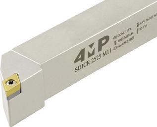
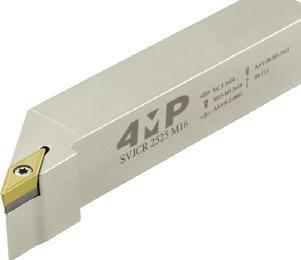
02 77 Tornitura / Turning
tornitura esterna SCLCR/L
di tornitura esterna per inserti avvitabili positivi
Articolo Reference Direzione dell’utensile R/L Hand Larghezza attacco (mm) Shank width (mm) Altezza attacco (mm) Shank height (mm) Distanza punta lato posteriore (mm) Distance cutting edge / rear face (mm) Lunghezza totale (mm) Total length (mm) Tipo di inserto Suitable insert Codice Code SCLCR 1010 E06-4MP destra / right 10 10 12 70 CC..0602 65 253 658 SCLCR 1212 F06-4MP destra / right 12 12 16 80 CC..0602 65 253 682 SCLCR 1616 H09-4MP destra / right 16 16 20 100 CC..09T3 65 253 690 SCLCR 2020 K09-4MP destra / right 20 20 25 125 CC..09T3 65 253 712 SCLCR 2525 M12-4MP destra / right 25 25 32 150 CC..1204 71 014 533 SCLCL 1010 E06-4MP sinistra / left 10 10 12 70 CC..0602 65 253 666 SCLCL 1212 F06-4MP sinistra / left 12 12 16 80 CC..0602 65 253 674 SCLCL 1616 H09-4MP sinistra / left 16 16 20 100 CC..09T3 65 253 704 SCLCL 2020 K09-4MP sinistra / left 20 20 25 125 CC..09T3 65 253 720 SCLCL 2525 M12-4MP sinistra / left 25 25 32 150 CC..1204 71 014 541 External turning toolholder SCLCR/L External turning tool for positive screw inserts CC...
tornitura esterna SDJCR/L Utensile di tornitura esterna per inserti avvitabili positivi DC... Articolo Reference Direzione dell’utensile R/L Hand Larghezza attacco (mm) Shank width(mm) Altezza attacco (mm) Shank height(mm) Distanza punta lato posteriore (mm) Distance cutting edge / rear face (mm) Lunghezza totale (mm) Total length (mm) Tipo di inserto Suitable insert Codice Code SDJCR 1616 H11-4MP destra / right 16 16 20 100 DC..11T3 65 253 763 SDJCR 2020 K11-4MP destra / right 20 20 25 125 DC..11T3 65 253 771 SDJCR 2525 M11-4MP destra / right 25 25 32 150 DC..11T3 65 253 798 SDJCL 1616 H11-4MP sinistra / left 16 16 20 100 DC..11T3 65 253 828 SDJCL 2020 K11-4MP sinistra / left 20 20 25 125 DC..11T3 65 253 836 SDJCL 2525 M11-4MP sinistra / left 25 25 32 150 DC..11T3 65 253 844 External turning toolholder SDJCR/L External turning tool for positive screw inserts DC...
tornitura esterna SVJBR/L Utensile di tornitura esterna per inserti avvitabili positivi VB.. / VC.. External toolholder SVJBR/L External turning tool for positive screw inserts VB... / VC... Articolo Reference Direzione dell’utensile R/L Hand Larghezza attacco (mm) Shank width (mm) Altezza attacco (mm) Shank height (mm) Distanza punta lato posteriore (mm) Distance cutting edge / rear face (mm) Lunghezza totale (mm) Total length (mm) Tipo di inserto Suitable insert Codice Code SVJBR 1616 H11-4MP destra / right 16 16 20 100 VB..1103 / VC..1103 71 014 576 SVJBR 2020 K11-4MP destra / right 20 20 25 125 VB..1103 / VC..1103 71 014 584 SVJBR 2020 K16-4MP destra / right 20 20 25 125 VB..1604 / VC..160471 014 592 SVJBR 2525 M16-4MP destra / right 25 25 32 150 VB..1604 / VC..160471 014 606 SVJBL 1616 H11-4MP sinistra / left 16 16 20 100 VB..1103 / VC..1103 71 014 614 SVJBL 2020 K11-4MP sinistra / left 20 20 25 125 VB..1103 / VC..1103 71 014 622 SVJBL 2020 K16-4MP sinistra / left 20 20 25 125 VB..1604 / VC..160471 014 630 SVJBL 2525 M16-4MP sinistra / left 25 25 32 150 VB..1604 / VC..160471 014 649 SDJCR 50°max SCLCR
Portautensili
Utensile
CC...
Portautensili
Portautensili
SVJBR
PORTA-INSERTI ISO DA TORNITURA INTERNI INTERNAL TURNING TOOLHOLDERS
T�po d� porta-�nserto Shank type
A : Acc � a � o con passagg � o d � refr � gerante
Steel shank w � th through coolant
E : Testa � n acc � a � o su corpo carburo
Carb � de shank w � th through coolant
C : Barra d � carburo
Carb � de shank
S : Acc � a � o senza refr � geraz � one Steel shank
Metodo d� f�ssagg�o dell’�nserto Clamp�ng system
F�ssagg�o super�ore senza foro Top clamp � ng W � thout hole F�ssagg�o super�ore con foro Top and hole clamp � ng
F�ssagg�o super�ore con foro + Sta�a Top and hole clamp � ng
F�ssagg�o super�ore con foro + leva Hole clamp � ng (Lever lock)
Inserto con foro Serragg�o v�te Screw on
Lunghezza totale Tool length
E-70 M-150 U-350
F-80 N-160 V-400
G-90 P-170 W-450
78 Tornitura / Turning
6
5 W K T V R S C D E L A-32 H-100 Q-180 X-speciale
R-200
Forma dell’utens�le Tool type
Forma dell’�nserto Insert shape
X-spec�al B-40 J-110
C-50 K-125 S-250
D-60 L-140 T-300
(mm)
3
C T M P S
4
2
D�ametro del corpo Shank d�ameter
1 A 1 25 2 R 3 P 4 12 9 C 5 L 6 N 7 C 10 R 8 Lunghezza
tagl�ente �nserto Cutt�ng edge length 9 Angolo d� spogl�a �nserto Insert clearance angle 7 D�rez�one d� tagl�o Cutt�ng d�rect�on 8 4MP Spec�f�c�tà Wedge clamp 10
del
Codifica Designation system
Tornitura, porta-inserti interni per inserti negativi
Turning, internal toolholders for negative inserts
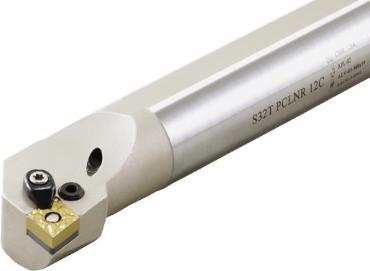
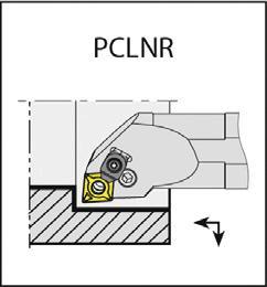
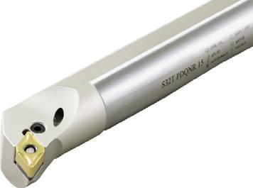
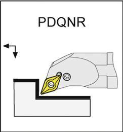
02 Tornitura / Turning 79
PCLNR/L
Porta-inserti di tornitura interna
Articolo Reference Direzione dell’utensile R/L Hand Diametro gambo (mm) Body shank diameter (mm) Diametro minimo foro (mm) Diameter for passage mini (mm) Lunghezza totale (mm) Total length (mm) Tipo di inserto Suitable insert Codice Code A25R-PCLNR12-4MP destra / right 25 >32 200 CN..1204 65 252 341 A32S-PCLNR12-4MP destra / right 32 >40 250 CN..1204 65 252 368 A25R-PCLNL12-4MP sinistra / left 25 >32 200 CN..1204 65 252 317 A32S-PCLNL12-4MP sinistra / left 32 >40 250 CN..1204 65 252 325 Internal turning toolholder PCLNR/L For negative inserts CN… 95° internal turning tool with through coolant. Porta-inserti di tornitura interna PDUNR/L Per inserti negativi DN... Utensile di tornitura interna a 93° con passaggio di refrigerante Internal turning toolholder PDUNR/L For negative inserts DN… 93° internal turning tool with through coolant. Articolo Reference Direzione dell’utensile R/L Hand Diametro gambo (mm) Body shank diameter (mm) Diametro minimo foro (mm) Diameter for passage mini (mm) Lunghezza totale (mm) Total length (mm) Tipo di inserto Suitable insert Codice Code A20P-PDUNR11-4MP* destra / right 20 > 25 170 DN..1104 71 014 657 A25S-PDUNR11-4MP* destra / right 25 > 32 200 DN..1104 71 014 665 A32S-PDUNR15-4MP* destra / right 32 > 40 250 DN..1506 71 014 673 A20P-PDUNL11-4MP* sinistra / left 20 > 25 170 DN..1104 71 014 681 A25S-PDUNL11-4MP* sinistra / left 25 > 32 200 DN..1104 71 014 703 A32S-PDUNL15-4MP* sinistra / left 32 > 40 250 DN..1506 71 014 711 PCLNR PDUNR
Per inserti negativi CN... Utensile di tornitura interna a 95° con passaggio di refrigerante
* Attenzione: Questi portautensili non sono dotati di sta�a / Beware : toolholders without clamp
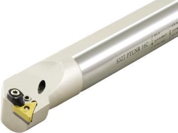
Tornitura, porta-inserti interni per inserti negativi
Turning, internal toolholders for negative inserts
Porta-inserti di tornitura interna PTUNR/L
Per inserti negativi TN...
Utensile di tornitura interna a 93° con passaggio di refrigerante
* Attenzione: Questi portautensili non sono dotati di sta�a / Beware : toolholders without clamp
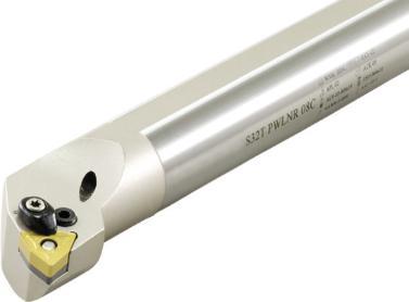
di tornitura
interna PWLNR/L
Per inserti negativi WN…
For negative inserts WN… 93° internal turning tool with through coolant. PWLNR
Utensile di tornitura interna a 95° con passaggio di refrigerante
Internal turning toolholder
* Attenzione: Questi portautensili non sono dotati di sta�a / Beware : toolholders without clamp
80 Tornitura / Turning
02
turning toolholder PTUNR/L For negative inserts TN… 93° internal turning tool with
coolant. Articolo Reference Direzione dell’utensile R/L Hand Diametro gambo (mm) Body shank diameter (mm) Diametro minimo foro (mm) Diameter for passage mini (mm) Lunghezza totale (mm) Total length (mm) Tipo di inserto Suitable insert Codice Code A16M-PTUNR16-4MP* destra / right 16 > 20 150 TN..1604 71 014 738 A20P-PTUNR16-4MP* destra / right 20 > 25 170 TN..1604 71 014 746 A25R-PTUNR16-4MP destra / right 25 > 32 200 TN..1604 71 014 754 A32S-PTUNR16-4MP destra / right 32 > 40 250 TN..1604 71 014 762 A16M-PTUNL16-4MP* sinistra / left 16 > 20 150 TN..1604 71 014 770 A20P-PTUNL16-4MP* sinistra / left 20 > 25 170 TN..1604 71 014 789 A25R-PTUNL16-4MP sinistra / left 25 > 32 200 TN..1604 71 014 797 A32S-PTUNL16-4MP sinistra / left 32 > 40 250 TN..1604 71 014 800
Internal
through
Porta-inserti
Articolo Reference Direzione dell’utensile R/L Hand Diametro gambo (mm) Body shank diameter (mm) Diametro minimo foro (mm) Diameter for passage mini (mm) Lunghezza totale (mm) Total length (mm) Tipo di inserto Suitable insert Codice Code A16M-PWLNR06-4MP* destra / right 16 >20 150 WN..0604 65 252 503 A20P-PWLNR06-4MP* destra / right 20 >25 170 WN..0604 65 252 511 A25R-PWLNR08-4MP destra / right 25 >32 200 WN..0804 65 252 538 A32S-PWLNR08-4MP destra / right 32 >40 250 WN..0804 65 252 546 A16M-PWLNL06-4MP* sinistra / left 16 >20 150 WN..0604 65 252 457 A20P-PWLNL06-4MP* sinistra / left 20 >25 170 WN..0604 65 252 465 A25R-PWLNL08-4MP sinistra / left 25 >32 200 WN..0804 65 252 473 A32S-PWLNL08-4MP sinistra / left 32 >40 250 WN..0804 65 252 481
PWLNR/L
PTUNR
Tornitura, porta-inserti interni per inserti positivi
Turning, internal toolholders for positive inserts
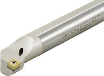
Porta-inserti di tornitura interna
Per inserti positivi CC... Utensile di tornitura interna a 95° con passaggio di refrigerante.
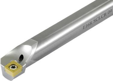
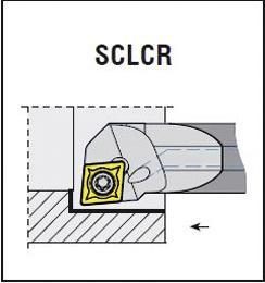
Per inserti positivi CC... Utensile di tornitura interna a 95° con passaggio di refrigerante.
02 81 Tornitura / Turning
SCLCR/L
Articolo Reference Direzione dell’utensile R/L Hand Diametro gambo (mm) Body shank diameter (mm) Diametro minimo foro (mm) Diameter for passage mini (mm) Lunghezza totale (mm) Total length (mm) Tipo di inserto Suitable insert Codice Code A08H-SCLCR06-4MP destra / right 8 >11 100 CC..0602 65 252 635 A10H-SCLCR06-4MP destra / right 10 >13 100 CC..0602 65 252 643 A12H-SCLCR06-4MP destra / right 12 >16 100 CC..0602 65 252 651 A16M-SCLCR09-4MP destra / right 16 >20 150 CC..09T3 65 252 708 A20P-SCLCR09-4MP destra / right 20 >25 170 CC..09T3 65 252 716 A25R-SCLCR12-4MP destra / right 25 >32 200 CC..1204 71 014 819 A08H-SCLCL06-4MP sinistra / left 8 >11 100 CC..0602 65 252 554 A10H-SCLCL06-4MP sinistra / left 10 >13 100 CC..0602 65 252 562 A12H-SCLCL06-4MP sinistra / left 12 >16 100 CC..0602 65 252 600 A16M-SCLCL09-4MP sinistra / left 16 >20 150 CC..09T3 65 252 619 A20P-SCLCL09-4MP sinistra / left 20 >25 170 CC..09T3 65 252 627 A25R-SCLCL12-4MP sinistra / left 25 >32 200 CC..1204 71 014 827 Internal turning toolholder SCLCR/L For positive inserts CC… 95°
turning
coolant. Portautensili per tornitura interna carburo SCLCL/R Barra in carburo.
Articolo Reference Direzione dell’utensile R/L Hand Diametro gambo (mm) Body shank diameter (mm) Diametro minimo foro (mm) Diameter for passage mini (mm) Lunghezza totale (mm) Total length (mm) Tipo di inserto Suitable insert Codice Code E08K-SCLCR06-4MP destra / right 8 >11 125 CC..0602 65 252 678 E10M-SCLCR06-4MP destra / right 10 >13 150 CC..0602 65 252 686 E12Q-SCLCR06-4MP destra / right 12 >16 180 CC..0602 65 252 694 E08K-SCLCL06-4MP sinistra / left 8 >11 125 CC..0602 65 252 570 E10M-SCLCL06-4MP sinistra / left 10 >13 150 CC..0602 65 252 589 E12Q-SCLCL06-4MP sinistra / left 12 >16 180 CC..0602 65 252 597 Carbide internal turning toolholder SCLCL/R Carbide body. For positive inserts CC… 95° internal turning tool with through coolant.
internal
tool with through
SCLCR
SCLCR
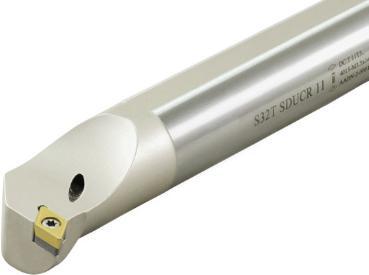
Tornitura, porta-inserti interni per inserti positivi
Turning, internal toolholders for positive inserts Porta-inserti di tornitura interna
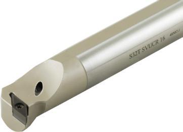
Per inserti positivi VB / VC…
Utensile per tornitura interna a 107,5° con refrigerazione attraverso il centro.
Internal turning toolholder SVQBR/L
For positive inserts VB / VC… 107,5° internal turning tool with through coolant.
82 Tornitura / Turning
02
SDUCR/L
Utensile
Articolo Reference Direzione dell’utensile R/L Hand Diametro gambo (mm) Body shank diameter (mm) Diametro minimo foro (mm) Diameter for passage mini (mm) Lunghezza totale (mm) Total length (mm) Tipo di inserto Suitable insert Codice Code A0810H-SDUCR07-4MP destra / right 10 >13 100 DC..0702 65 252 775 A10H-SDUCR07-4MP destra / right 10 >13 100 DC..0702 65 252 783 A12H-SDUCR07-4MP destra / right 12 >16 100 DC..0702 65 252 791 A16M-SDUCR07-4MP destra / right 16 >20 150 DC..0702 65 252 805 A20P-SDUCR11-4MP destra / right 20 >25 250 DC..11T3 65 252 813 A25R-SDUCR11-4MP destra / right 25 >32 200 DC..11T3 71 014 835 A0810H-SDUCL07-4MP sinistra / left 10 >13 100 DC..0702 65 252 724 A10H-SDUCL07-4MP sinistra / left 10 >13 100 DC..0702 65 252 732 A12H-SDUCL07-4MP sinistra / left 12 >16 100 DC..0702 65 252 740 A16M-SDUCL07-4MP sinistra / left 16 >20 150 DC..0702 65 252 759 A20P-SDUCL11-4MP sinistra / left 20 >25 170 DC..11T3 65 252 767 A25R-SDUCL11-4MP sinistra / left 25 >32 200 DC..11T3 71 014 843
turning toolholder SDUCR/L For positive inserts DC… 93° internal turning tool with through coolant.
Per inserti positivi DC...
di tornitura interna a 93° con passaggio di refrigerante.
Internal
Porta-inserti di tornitura interna SVQBR/L
Articolo Reference Direzione dell’utensile R/L Hand Diametro gambo (mm) Body shank diameter (mm) Diametro minimo foro (mm) Diameter for passage mini (mm) Lunghezza totale (mm) Total length (mm) Tipo di inserto Suitable insert Codice Code A20Q-SVQBR11-4MP destra / right 20 > 25 180 VB..1103 / VC..1103 71 014 851 A25S-SVQBR16-4MP destra / right 25 > 32 250 VB..1604 / VC..160471 014 878 A32S-SVQBR16-4MP destra / right 32 > 40 250 VB..1604 / VC..160471 014 886 A20Q-SVQBL11-4MP sinistra / left 20 > 25 180 VB..1103 / VC..1104 71 014 894 A25S-SVQBL16-4MP sinistra / left 25 > 32 250 VB..1604 / VC..160471 014 908 A32S-SVQBL16-4MP sinistra / left 32 > 40 250 VB..1604 / VC..160471 014 916 SVQBR
SDUCR
Accessori per porta-inserti
Toolholders accessories
Cuneo di supporto
Cuneo di supporto
Cuneo di supporto
02 83 Tornitura / Turning Sottoplacchetta porta-inserti tornitura AACN
Articolo Reference Riferimento porta-inserto Toolholder reference Codice Code AACN-2-0001-4MP SCLCR/L 09 65 251 876 AACN-3-0001-4MP PCLNR/L 12 65 251 892 AACN-2-0003-4MP SCLCR/L 12 71 014 568 Shim AACN Sottoplacchetta porta-inserti tornitura AADN
Articolo Reference Riferimento porta-inserto Toolholder reference Codice Code AADN-SD317-4MP PDJNR/L 11 65 251 922 AADN-3-0001-4MP PDJNR/L 15 65 251 914 AADN-2-0001-4MP SDJCR/L 11 65 251 906 Shim AADN Sottoplacchetta porta-inserti tornitura AASN
Articolo Reference Riferimento porta-inserto Toolholder reference Codice Code AASN-3-0004-4MP PSSNR/L12 67 467 612 Shim AASN Sottoplacchetta porta-inserti tornitura AATN Cuneo di supporto Articolo Reference Riferimento porta-inserto Toolholder reference Codice Code AATN-3-0025-4MP PTUNR/L 16 ; PTJNR/L 16 ext 65 251 949 Shim AATN Sottoplacchetta porta-inserti tornitura AAVN Cuneo di supporto Articolo Reference Riferimento porta-inserto Toolholder reference Codice Code AAVN-2-0002-4MP SVQBR/L 16 - SVJBR/L 16 65 251 957 Shim AAVN Sottoplacchetta porta-inserti tornitura AAWN Cuneo di supporto Articolo Reference Riferimento porta-inserto Toolholder reference Codice Code AAWN-SW317-4MP PWLNR/L 06 65 251 973 AAWN-3-0001-4MP PWLNR/L 08 65 251 965 Shim AAWN
Accessori per porta-inserti Toolholders accessories
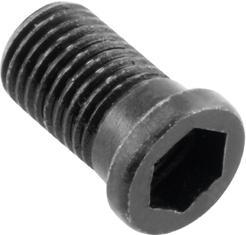
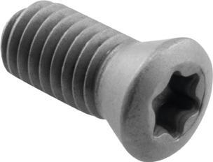
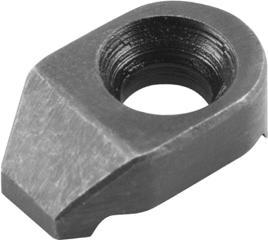
02 84 Tornitura / Turning
dello spessore Rivetto per lo spessore Articolo Reference Riferimento porta-inserto Toolholder reference Codice Code AAY-01-4MP PWLNR/L 06 - PTJNR/L 16 - PDJNR/L 11 - PWLNR/L 06 - PTUNR/L 16 - PDQNR 11 65 251 981 AAY-02-4MP PWLNR/L 08 - PDJNR/L 15 - PCLNR/L 12 - PSSNR/L12 65 252 007 Shim pin Rivet for shim
dello spessore Vitedi blocco di supporto Articolo Reference Riferimento porta-inserto Toolholder reference Diametro (mm) Diameter (mm) Lunghezza (mm) Length (mm) Codice Code AAV-06-M3.5x11-4MP SVQBL/R 16 - SCLCL/R 09 - SVJBR/L 16 - SDJCL/R 11 M3.5 11,3 65 252 082 AAV-07-M4.5X13-4MP SCLCL:R 12 M4.5 13 67 467 728 Shim screw Vite inserti Vite torx Articolo Reference Diametro (mm) Diameter (mm) Lunghezza (mm) Length (mm) Codice Code 3008-M2.5x6-4MP M2.5 6 65 252 120 4008-M2.5x6-4MP M2.5 5,8 65 252 066 1008-M3x8-4MP M3 8 65 252 104 1510-M3.5x9-4MP M3.5 9,1 65 252 112 4015-M3.5x9-4MP M3.5 8,7 65 252 155 4015-M3.5x11-4MP M3.5 10,7 65 252 139 4015-M3.5x14-4MP M3.5 13,7 65 252 147 4015-M4x9-4MP M4 9 65 252 163 1515-M4x11-4MP M4 11,8 65 252 031 4015-M4X11-4MP M4 11 67 467 744 1020-M4.5X16-4MP M4.5 16 67 467 787
Sta a Articolo Reference Riferimento porta-inserto Toolholder reference Codice Code ACK-05-4MP SIR/L 16 - PWLNR/L 08 - PDJNR/L 15 - PCLNR/L 12 - PSSNR/L12 - PTJNR/L 22 65 252 015 Clamp
Molla
Vite
Screw Torx screw
Accessori per porta-inserti Toolholders accessories
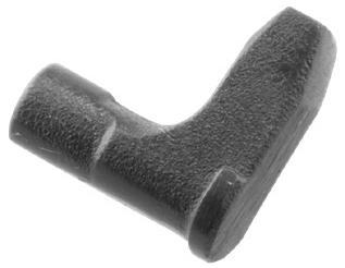
Allen
02 85 Tornitura / Turning
Articolo Reference Riferimento porta-inserto Toolholder reference Codice Code APL-03-4MP PDJNR/L 15 - PWLNR/L 06 - PTJNR/L 16 - PDJNR/L 11 65 251 825 APL-01-4MP PDQNR/L 11 - PWLNR/06 - PTUNR/L 16 65 251 809 APL-02-4MP PWLNR/L 08 - PCLNR/L 12 - PSSNR/L12 - PTJNR/L 22 65 251 817 Lever Vite della leva Articolo Reference Riferimento porta-inserto Toolholder reference Lunghezza totale (mm) Total length (mm) Codice Code ALV-01-M6x14-4MP PWLNR/L 06 - PDQNR/L 11 14 65 251 833 ALV-02-M6x17-4MP PDQNR/L 11 - PTUNR/R 16 - PDJNR/L 11 - PTJNR/L 16 - PWLNR/L 06 17 65 251 841 ALV-03-M8x19-4MP PWLNR/L 08 - PCLNR/L 12 - PSSNR/L 12 19,8 65 251 868 ALV-08-M8X16-4MP PCLNR/L 12 16 66 203 344 Lever screw Chiave di serraggio Chiave torx Articolo Reference Dimensione Dimension Codice Code 80-T10-4MP T10 65 252 198 80-T15-4MP T15 65 252 201 80-T08-4MP T08 65 252 171 80-T20-4MP T20 67 430 891 Wrench Torx wrench Chiave di serraggio Chiave
Articolo Reference Riferimento porta-inserto Toolholder reference Dimensione Dimension Codice Code AAL-02-2.5-4MP PWLNR/L 1616 H06, 2020 K06, 2525 M06; PTJNR/L 2020 K16, 2525 M16; PDJNR/L 1616 H11, 2020 K11, 2525 M11; A20P PWLNR/L 06, A25R PWLNR/L 06, A32S PWLNR/L 06; A25R PTUNR/L 16, A32S PTUNR/L 16; A20P PDQNR/L 11, A25R PDQNR/L 11 2,5 65 252 228 AAL-03-3-4MP MWLNR/L 2020 K08, 2525 M08; PDJNR/L 2020 K15, 2525 M15; PCLNR/L 1616 H12, 2020 K12, 2525 M12, 3232 P12; A25R PCLNR/L 12, A32S PCLNR/L 12, PSSNR/L 12 3 65 252 236 Wrench Allen wrench
Leva
86 Tornitura / Turning
PORTAUTENSILI
Articolo Reference Leva Lever Vite della leva Lever screw Spessore Shim Rivetto per lo spessore Shim spring Sta�a Clamp Vite per sta�a Clamp screw Raccordo Coolant nozzle Chiave Key Anello Ring Tappo Plug PCLNL/R PCLNL 1616 H12-4MP 65 253 305 APL-02-4MP 65251817 ALV-03-M8x19-4MP 65251868 AACN-3-0001-4MP 65251892 AAY-02-4MP 65252007 AAL-03-3-4MP 65252236 PCLNL 2020 K12C-4MP 65 253 321 APL-02-4MP 65251817 ALV-03-M8x19-4MP 65251868 AACN-3-0001-4MP 65251892 AAY-02-4MP 65252007 ACK-05-4MP 65252015 1515-M4x11-4MP 65252031 AAL-03-3-4MP 65252236 PCLNL 2525 M12C-4MP 65 253 356 APL-02-4MP 65251817 ALV-03-M8x19-4MP 65251868 AACN-3-0001-4MP 65251892 AAY-02-4MP 65252007 ACK-05-4MP 65252015 1515-M4x11-4MP 65252031 AAL-03-3-4MP 65252236 PCLNL 3232 P12C-4MP 65 253 372 APL-02-4MP 65251817 ALV-03-M8x19-4MP 65251868 AACN-3-0001-4MP 65251892 AAY-02-4MP 65252007 ACK-05-4MP 65252015 1515-M4x11-4MP 65252031 AAL-03-3-4MP 65252236 PCLNR 1616 H12-4MP 65 253 291 APL-02-4MP 65251817 ALV-03-M8x19-4MP 65251868 AACN-3-0001-4MP 65251892 AAY-02-4MP 65252007 AAL-03-3-4MP 65252236 PCLNR 2020 K12C-4MP 65 253 313 APL-02-4MP 65251817 ALV-03-M8x19-4MP 65251868 AACN-3-0001-4MP 65251892 AAY-02-4MP 65252007 ACK-05-4MP 65252015 1515-M4x11-4MP 65252031 AAL-03-3-4MP 65252236 PCLNR 2525 M12C-4MP 65 253 348 APL-02-4MP 65251817 ALV-03-M8x19-4MP 65251868 AACN-3-0001-4MP 65251892 AAY-02-4MP 65252007 ACK-05-4MP 65252015 1515-M4x11-4MP 65252031 AAL-03-3-4MP 65252236 PCLNR 3232 P12C-4MP 65 253 364 APL-02-4MP 65251817 ALV-03-M8x19-4MP 65251868 AACN-3-0001-4MP 65251892 AAY-02-4MP 65252007 ACK-05-4MP 65252015 1515-M4x11-4MP 65252031 AAL-03-3-4MP 65252236 PCLNL 2020 K12-AR-4MP 69 109 047 APL-02-4MP 65251817 ALV-03-M8x19-4MP 65251868 AACN-3-0001-4MP 65251892 AAY-02-4MP 65252007 ACK-05-4MP 65252015 1515-M4x11-4MP 65252031 AN-01-4MP 71209938 AAL-03-3-4MP 65252236 AXR-01-4MP 71209911 2705-G1/8X5.5-4MP 71209946 PCLNL 2525 M12-AR-4MP 69 109 055 APL-02-4MP 65251817 ALV-03-M8x19-4MP 65251868 AACN-3-0001-4MP 65251892 AAY-02-4MP 65252007 ACK-05-4MP 65252015 1515-M4x11-4MP 65252031 AN-01-4MP 71209938 AAL-03-3-4MP 65252236 AXR-01-4MP 71209911 2705-G1/8X5.5-4MP 71209946 PCLNR 2020 K12-AR-4MP 69 109 063 APL-02-4MP 65251817 ALV-03-M8x19-4MP 65251868 AACN-3-0001-4MP 65251892 AAY-02-4MP 65252007 ACK-05-4MP 65252015 1515-M4x11-4MP 65252031 AN-01-4MP 71209938 AAL-03-3-4MP 65252236 AXR-01-4MP 71209911 2705-G1/8X5.5-4MP 71209946 PCLNR 2525 M12-AR-4MP 69 109 071 APL-02-4MP 65251817 ALV-03-M8x19-4MP 65251868 AACN-3-0001-4MP 65251892 AAY-02-4MP 65252007 ACK-05-4MP 65252015 1515-M4x11-4MP 65252031 AN-01-4MP 71209938 AAL-03-3-4MP 65252236 AXR-01-4MP 71209911 2705-G1/8X5.5-4MP 71209946 PDJNL/R PDJNL 1616 H11-4MP 65 253 399 APL-01-4MP 65251809 ALV-02-M6x17-4MP 65251841 AADN-SD317-4MP 65251922 AAY-01-4MP 65251981 AAL-02-2.5-4MP 65252228 PDJNL 2020 K11-4MP 65 253 410 APL-01-4MP 65251809 ALV-02-M6x17-4MP 65251841 AADN-SD317-4MP 65251922 AAY-01-4MP 65251981 AAL-02-2.5-4MP 65252228 PDJNL 2020 K15-4MP 65 253 437 APL-03-4MP 65251825 ALV-03-M8x19-4MP 65251868 AADN-3-0001-4MP 65251914 AAY-02-4MP 65252007 ACK-05-4MP 65252015 1515-M4x11-4MP 65252031 AAL-03-3-4MP 65252236 PDJNL 2525 M11-4MP 65253453 APL-01-4MP 65251809 ALV-02-M6x17-4MP 65251841 AADN-SD317-4MP 65251922 AAY-01-4MP 65251981 AAL-02-2.5-4MP 65252228 PDJNL 2525 M15-4MP 65 253 488 APL-03-4MP 65251825 ALV-03-M8x19-4MP 65251868 AADN-3-0001-4MP 65251914 AAY-02-4MP 65252007 ACK-05-4MP 65252015 1515-M4x11-4MP 65252031 AAL-03-3-4MP 65252236 PDJNR 1616 H11-4MP 65 253 380 APL-01-4MP 65251809 ALV-02-M6x17-4MP 65251841 AADN-SD317-4MP 65251922 AAY-01-4MP 65251981 AAL-02-2.5-4MP 65252228 PDJNR 2020 K11-4MP 65 253 402 APL-01-4MP 65251809 ALV-02-M6x17-4MP 65251841 AADN-SD317-4MP 65251922 AAY-01-4MP 65251981 AAL-02-2.5-4MP 65252228 PDJNR 2020 K15-4MP 65 253 429 APL-03-4MP 65251825 ALV-03-M8x19-4MP 65251868 AADN-3-0001-4MP 65251914 AAY-02-4MP 65252007 ACK-05-4MP 65252015 1515-M4x11-4MP 65252031 AAL-03-3-4MP 65252236 PDJNR 2525 M11-4MP 65 253 445 APL-01-4MP 65251809 ALV-02-M6x17-4MP 65251841 AADN-SD317-4MP 65251922 AAY-01-4MP 65251981 AAL-02-2.5-4MP 65252228 PDJNR 2525 M15-4MP 65 253 461 APL-03-4MP 65251825 ALV-03-M8x19-4MP 65251868 AADN-3-0001-4MP 65251914 AAY-02-4MP 65252007 ACK-05-4MP 65252015 1515-M4x11-4MP 65252031 AAL-03-3-4MP 65252236 PSSNR/L PSSNL 2020 K12C-4MP 67 467 426 APL-02-4MP 65251817 ALV-03-M8x19-4MP 65251868 AASN-3-0004-4MP 67467612 AAY-02-4MP 65252007 ACK-05-4MP 65252015 4015-M4x11-4MP 67467744 AAL-03-3-4MP 65252236 PSSNL 2525 M12C-4MP 67 467 434 APL-02-4MP 65251817 ALV-03-M8x19-4MP 65251868 AASN-3-0004-4MP 67467612 AAY-02-4MP 65252007 ACK-05-4MP 65252015 4015-M4x11-4MP 67467744 AAL-03-3-4MP 65252236 PSSNL 3232 P12C-4MP 67 467 442 APL-02-4MP 65251817 ALV-03-M8x19-4MP 65251868 AASN-3-0004-4MP 67467612 AAY-02-4MP 65252007 ACK-05-4MP 65252015 4015-M4x11-4MP 67467744 AAL-03-3-4MP 65252236 PSSNR 2020 K12C-4MP 67 467 469 APL-02-4MP 65251817 ALV-03-M8x19-4MP 65251868 AASN-3-0004-4MP 67467612 AAY-02-4MP 65252007 ACK-05-4MP 65252015 4015-M4x11-4MP 67467744 AAL-03-3-4MP 65252236 PSSNR 2525 M12C-4MP 67 467 477 APL-02-4MP 65251817 ALV-03-M8x19-4MP 65251868 AASN-3-0004-4MP 67467612 AAY-02-4MP 65252007 ACK-05-4MP 65252015 4015-M4x11-4MP 67467744 AAL-03-3-4MP 65252236 PSSNR 3232 P12C-4MP 67 467 485 APL-02-4MP 65251817 ALV-03-M8x19-4MP 65251868 AASN-3-0004-4MP 67467612 AAY-02-4MP 65252007 ACK-05-4MP 65252015 4015-M4x11-4MP 67467744 AAL-03-3-4MP 65252236
TABELLE DI CORRISPONDENZE
ESTERNI/ACCESSORI TABLES OF EQUIVALENCES EXTERNAL TOOLHOLDERS/ACCESSORIES
87 Tornitura / Turning Articolo Reference Leva Lever Vite per leva Lever screw Spessore Shim Rivetto per lo spessore Shim spring Sta�a Clamp Vite per sta�a Clamp screw Vite dello spessore Shim screw Vite inserto Screw Chiave Key PTJNL/R PTJNL 2020 K16-4MP 65 253 518 APL-01-4MP 65251809 ALV-02-M6x17-4MP 65251841 AATN-3-0025-4MP 65251949 AAY-01-4MP 65251981 AAL-02-2.5-4MP 65252228 PTJNL 2525 M16-4MP 65 253 534 APL-01-4MP 65251809 ALV-02-M6x17-4MP 65251841 AATN-3-0025-4MP 65251949 AAY-01-4MP 65251981 AAL-02-2.5-4MP 65252228 PTJNR 2020 K16-4MP 65 253 496 APL-01-4MP 65251809 ALV-02-M6x17-4MP 65251841 AATN-3-0025-4MP 65251949 AAY-01-4MP 65251981 AAL-02-2.5-4MP 65252228 PTJNR 2525 M16-4MP 65 253 526 APL-01-4MP 65251809 ALV-02-M6x17-4MP 65251841 AATN-3-0025-4MP 65251949 AAY-01-4MP 65251981 AAL-02-2.5-4MP 65252228 PWLNL/R PWLNL 1616 H06-4MP 65 253 550 APL-01-4MP 65251809 ALV-02-M6x17-4MP 65251841 AAWN-SW317-4MP 65251973 AAY-01-4MP 65251981 AAL-02-2.5-4MP 65252228 PWLNL 2020 K06-4MP 65 253 577 APL-01-4MP 65251809 ALV-02-M6x17-4MP 65251841 AAWN-SW317-4MP 65251973 AAY-01-4MP 65251981 AAL-02-2.5-4MP 65252228 PWLNL 2020 K08-4MP 65 253 593 APL-02-4MP 65251817 ALV-03-M8x19-4MP 65251868 AAWN-3-0001-4MP 65251965 AAY-02-4MP 65252007 ACK-05-4MP 65252015 1515-M4x11-4MP 65252031 AAL-03-3-4MP 65252236 PWLNL 2525 M06-4MP 65 253 615 APL-01-4MP 65251809 ALV-02-M6x17-4MP 65251841 AAWN-SW317-4MP 65251973 AAY-01-4MP 65251981 AAL-02-2.5-4MP 65252228 PWLNL 2525 M08-4MP 65 253 631 APL-02-4MP 65251817 ALV-03-M8x19-4MP 65251868 AAWN-3-0001-4MP 65251965 AAY-02-4MP 65252007 ACK-05-4MP 65252015 1515-M4x11-4MP 65252031 AAL-03-3-4MP 65252236 PWLNR 1616 H06-4MP 65 253 542 APL-01-4MP 65251809 ALV-02-M6x17-4MP 65251841 AAWN-SW317-4MP 65251973 AAY-01-4MP 65251981 AAL-02-2.5-4MP 65252228 PWLNR 2020 K06-4MP 65 253 569 APL-01-4MP 65251809 ALV-02-M6x17-4MP 65251841 AAWN-SW317-4MP 65251973 AAY-01-4MP 65251981 AAL-02-2.5-4MP 65252228 PWLNR 2020 K08-4MP 65 253 585 APL-02-4MP 65251817 ALV-03-M8x19-4MP 65251868 AAWN-3-0001-4MP 65251965 AAY-02-4MP 65252007 ACK-05-4MP 65252015 1515-M4x11-4MP 65252031 AAL-03-3-4MP 65252236 PWLNR 2525 M06-4MP 65 253 607 APL-01-4MP 65251809 ALV-02-M6x17-4MP 65251841 AAWN-SW317-4MP 65251973 AAY-01-4MP 65251981 AAL-02-2.5-4MP 65252228 PWLNR 2525 M08-4MP 65 253 623 APL-02-4MP 65251817 ALV-03-M8x19-4MP 65251868 AAWN-3-0001-4MP 65251965 AAY-02-4MP 65252007 ACK-05-4MP 65252015 1515-M4x11-4MP 65252031 AAL-03-3-4MP 65252236 SCLCL/R SCLCL 1010 E06-4MP 65 253 666 4008-M2.5x6-4MP 65252066 80-T08-4MP 65252171 SCLCL 1212 F06-4MP 65 253 674 4008-M2.5x6-4MP 65252066 80-T08-4MP 65252171 SCLCL 1616 H09-4MP 65 253 704 AACN-2-0001-4MP 65251876 AAV-06-M3.5x11-4MP 65252082 4015-M3.5x14-4MP 65252147 80-T15-4MP 65252201 SCLCL 2020 K09-4MP 65 253 720 AACN-2-0001-4MP 65251876 AAV-06-M3.5x11-4MP 65252082 4015-M3.5x14-4MP 65252147 80-T15-4MP 65252201 SCLCL 2525 M12-4MP 71 014 541 AACN-3-001-4MP 71014568 AAV-07-M4.5x13-4MP 67467728 1020-M4.5X16-4MP 67467787 80-T20-4MP 67430891 SCLCR 1010 E06-4MP 65 253 658 4008-M2.5x6-4MP 65252066 80-T08-4MP 65252171 SCLCR 1212 F06-4MP 65 253 682 4008-M2.5x6-4MP 65252066 80-T08-4MP 65252171 SCLCR 1616 H09-4MP 65 253 690 AACN-2-0001-4MP 65251876 AAV-06-M3.5x11-4MP 65252082 4015-M3.5x14-4MP 65252147 80-T15-4MP 65252201 SCLCR 2020 K09-4MP 65 253 712 AACN-2-0001-4MP 65251876 AAV-06-M3.5x11-4MP 65252082 4015-M3.5x14-4MP 65252147 80-T15-4MP 65252201 SCLCR 2525 M12-4MP 71 014 533 AACN-3-001-4MP 71014568 AAV-07-M4.5x13-4MP 67467728 1020-M4.5X16-4MP 67467787 80-T20-4MP 67430891 SDJCL/R SDJCL 1616 H11-4MP 65 253 828 AADN-2-0001-4MP 65251906 AAV-06-M3.5x11-4MP 65252082 4015-M3.5x14-4MP 65252147 80-T15-4MP 65252201 SDJCL 2020 K11-4MP 65 253 836 AADN-2-0001-4MP 65251906 AAV-06-M3.5x11-4MP 65252082 4015-M3.5x14-4MP 65252147 80-T15-4MP 65252201 SDJCL 2525 M11-4MP 65 253 844 AADN-2-0001-4MP 65251906 AAV-06-M3.5x11-4MP 65252082 4015-M3.5x14-4MP 65252147 80-T15-4MP 65252201 SDJCR 1212 F07-4MP 65 253 755 4008-M2.5x6-4MP 65252066 80-T08-4MP 65252171 SDJCR 1616 H11-4MP 65 253 763 AADN-2-0001-4MP 65251906 AAV-06-M3.5x11-4MP 65252082 4015-M3.5x14-4MP 65252147 80-T15-4MP 65252201 SDJCR 2020 K11-4MP 65 253 771 AADN-2-0001-4MP 65251906 AAV-06-M3.5x11-4MP 65252082 4015-M3.5x14-4MP 65252147 80-T15-4MP 65252201 SDJCR 2525 M11-4MP 65 253 798 AADN-2-0001-4MP 65251906 AAV-06-M3.5x11-4MP 65252082 4015-M3.5x14-4MP 65252147 80-T15-4MP 65252201 SVJBL/R SVJBL 1616 H11-4MP 71 014 614 4008-M2.5X6-4MP 65252066 80-T08-4MP 65252171 SVJBL 2020 K11-4MP 71 014 622 4008-M2.5X6-4MP 65252066 80-T08-4MP 65252171 SVJBL 2020 K16-4MP 71 014 630 AAVN-2-0002-4MP 65251957 AAV-06-M3.5X11-4MP 65252082 4015-M3.5X14-4MP 65252147 80-T15-4MP 65252201 SVJBL 2525 M16-4MP 71 014 649 AAVN-2-0002-4MP 65251957 AAV-06-M3.5X11-4MP 65252082 4015-M3.5X14-4MP 65252147 80-T15-4MP 65252201 SVJBR 1616 H11-4MP 71 014 576 4008-M2.5X6-4MP 65252066 80-T08-4MP 65252171 SVJBR 2020 K11-4MP 71 014 584 4008-M2.5X6-4MP 65252066 80-T08-4MP 65252171 SVJBR 2020 K16-4MP 71 014 592 AAVN-2-0002-4MP 65251957 AAV-06-M3.5X11-4MP 65252082 4015-M3.5X14-4MP 65252147 80-T15-4MP 65252201 SVJBR 2525 M16-4MP 71 014 606 AAVN-2-0002-4MP 65251957 AAV-06-M3.5X11-4MP 65252082 4015-M3.5x14-4MP 65252147 80-T15-4MP 65252201 TABELLE DI CORRISPONDENZE PORTAUTENSILI ESTERNI/ACCESSORI TABLES OF EQUIVALENCES EXTERNAL TOOLHOLDERS/ACCESSORIES
88 Tornitura / Turning
TOOLHOLDERS/ACCESSORIES Articolo Reference Leva Lever Vite per la leva Lever screw Spessore Shim Rivetto per lo spessore Shim spring Vite dello spessore Shim screw Vite inserto Screw Chiave Key SDUCL/R A0810H SDUCL 07-4MP 65 252 724 4008-M2.5x6-4MP 65252066 80-T08-4MP 65252171 A0810H SDUCR 07-4MP 65 252 775 4008-M2.5x6-4MP 65252066 80-T08-4MP 65252171 A10H SDUCL 07-4MP 65 252 732 4008-M2.5x6-4MP 65252066 80-T08-4MP 65252171 A10H SDUCR 07-4MP 65 252 783 4008-M2.5x6-4MP 65252066 80-T08-4MP 65252171 A12H SDUCL 07-4MP 65 252 740 4008-M2.5x6-4MP 65252066 80-T08-4MP 65252171 A12H SDUCR 07-4MP 65 252 791 4008-M2.5x6-4MP 65252066 80-T08-4MP 65252171 A16M SDUCL 07-4MP 65 252 759 4008-M2.5x6-4MP 65252066 80-T08-4MP 65252171 A16M SDUCR 07-4MP 65 252 805 4008-M2.5x6-4MP 65252066 80-T08-4MP 65252171 A20P SDUCL 11-4MP 65 252 767 4015-M3.5x11-4MP 65252139 80-T15-4MP 65252201 A20S SDUCR 11-4MP 65 252 813 4015-M3.5x11-4MP 65252139 80-T15-4MP 65252201 A25R-SDUCL 11-4MP 71 014 843 4015-M3.5x11-4MP 65252139 80-T15-4MP 65252201 A2R-SDUCR 11-4MP 71 014 835 4015-M3.5x11-4MP 65252139 80-T15-4MP 65252201 SCLCL/R A08H SCLCL 06-4MP 65 252 554 4008-M2.5x6-4MP 65252066 80-T08-4MP 65252171 A08H SCLCR 06-4MP 65 252 635 4008-M2.5x6-4MP 65252066 80-T08-4MP 65252171 A10H SCLCL 06-4MP 65 252 562 4008-M2.5x6-4MP 65252066 80-T08-4MP 65252171 A10H SCLCR 06-4MP 65 252 643 4008-M2.5x6-4MP 65252066 80-T08-4MP 65252171 A12H SCLCL 09-4MP 65 252 600 4008-M2.5x6-4MP 65252066 80-T08-4MP 65252171 A12H SCLCR 06-4MP 65 252 651 4008-M2.5x6-4MP 65252066 80-T08-4MP 65252171 A16M SCLCL 09-4MP 65 252 619 4015-M3.5x9-4MP 65252155 80-T15-4MP 65252201 A16M SCLCR 09-4MP 65 252 708 4015-M3.5x9-4MP 65252155 80-T15-4MP 65252201 A20P SCLCL 09-4MP 65 252 627 4015-M3.5x9-4MP 65252155 80-T15-4MP 65252201 A20P SCLCR 09-4MP 65 252 716 4015-M3.5x9-4MP 65252155 80-T15-4MP 65252201 A25R SCLCL 12-4MP 71 014 827 AACN-2-0003-4MP 71014568 AAV-10-M4.5X8-4MP 71274810 4020-M4.5x12-4MP 71014568 80-T20-4MP 67430891 A25R SCLCR 12-4MP 71 014 819 AACN-2-0003-4MP 71014568 AAV-10-M4.5X8-4MP 71274810 4020-M4.5x12-4MP 71014568 80-T20-4MP 67430891 PWLNL/R A16 M PWLNL 06-4MP 65 252 457 APL-01-4MP 65251809 ALV-01-M6x14-4MP 65251833 AAWN-SW317-4MP 65251973 AAY-01-4MP 65251981 AAL-02-2.5-4MP 65252228 A16 M PWLNR 06-4MP 65 252 503 APL-01-4MP 65251809 ALV-01-M6x14-4MP 65251833 AAWN-SW317-4MP 65251973 AAY-01-4MP 65251981 AAL-02-2.5-4MP 65252228 A20P PWLNL 06-4MP 65 252 465 APL-01-4MP 65251809 ALV-01-M6x14-4MP 65251833 AAWN-SW317-4MP 65251973 AAY-01-4MP 65251981 AAL-02-2.5-4MP 65252228 A20P PWLNR 06-4MP 65 252 511 APL-01-4MP 65251809 ALV-01-M6x14-4MP 65251833 AAWN-SW317-4MP 65251973 AAY-01-4MP 65251981 AAL-02-2.5-4MP 65252228
TABELLE DI CORRISPONDENZE PORTA ATTREZZI INTERNI/ACCESSORI TABLES OF EQUIVALENCES INTERNAL
89 Tornitura / Turning Articolo Reference Leva Lever Vite per la leva Lever screw Spessore Shim Rivetto per lo spessore Shim spring Sta�a Clamp Vite per sta�a Clamp screw Vite dello spessore Shim screw Vite inserto Screw Chiave Key A25R PWLNL 08-4MP 65 252 473 APL-02-4MP 65251817 ALV-03-M8x19-4MP 65251868 AAWN-3-0001-4MP 65251965 AAY-02-4MP 65252007 ACK-05-4MP 65252015 1515-M4x11-4MP 65252031 AAL-03-3-4MP 65252236 A25R PWLNR 08-4MP 65 252 538 APL-02-4MP 65251817 ALV-03-M8x19-4MP 65251868 AAWN-3-0001-4MP 65251965 AAY-02-4MP 65252007 ACK-05-4MP 65252015 1515-M4x11-4MP 65252031 AAL-03-3-4MP 65252236 A32S PWLNL 08-4MP 65 252 481 APL-02-4MP 65251817 ALV-03-M8x19-4MP 65251868 AAWN-3-0001-4MP 65251965 AAY-02-4MP 65252007 ACK-05-4MP 65252015 1515-M4x11-4MP 65252031 AAL-03-3-4MP 65252236 A32S PWLNR 08-4MP 65 252 546 APL-02-4MP 65251817 ALV-03-M8x19-4MP 65251868 AAWN-3-0001-4MP 65251965 AAY-02-4MP 65252007 ACK-05-4MP 65252015 1515-M4x11-4MP 65252031 AAL-03-3-4MP 65252236 PCLNL/R A25R PCLNL 12-4MP 65 252 317 APL-02-4MP 65251817 ALV-08-M8x16-4MP 62203344 AACN-3-0001-4MP 65251892 AAY-02-4MP 65252007 ACK-05-4MP 65252015 1515-M4x11-4MP 65252031 AAL-03-3-4MP 65252236 A25R PCLNR 12-4MP 65 252 341 APL-02-4MP 65251817 ALV-08-M8x16-4MP 62203344 AACN-3-0001-4MP 65251892 AAY-02-4MP 65252007 ACK-05-4MP 65252015 1515-M4x11-4MP 65252031 AAL-03-3-4MP 65252236 A32S PCLNL 12-4MP 65 252 325 APL-02-4MP 65251817 ALV-03-M8x19-4MP 65251868 AACN-3-0001-4MP 65251892 AAY-02-4MP 65252007 ACK-05-4MP 65252015 1515-M4x11-4MP 65252031 AAL-03-3-4MP 65252236 A32S PCLNR 12-4MP 65 252 368 APL-02-4MP 65251817 ALV-03-M8x19-4MP 65251868 AACN-3-0001-4MP 65251892 AAY-02-4MP 65252007 ACK-05-4MP 65252015 1515-M4x11-4MP 65252031 AAL-03-3-4MP 65252236 PDUNL/R A20P PDUNL 11-4MP 71 014 681 APL-01-4MP 65251809 ALV-01-M6x14-4MP 65251833 AADN-SD317-4MP 65251922 AAY-01-4MP 65251981 AAL-02-2.5-4MP 65252228 A20P PDUNR 11-4MP 71 014 657 APL-01-4MP 65251809 ALV-01-M6x14-4MP 65251833 AADN-SD317-4MP 65251922 AAY-01-4MP 65251981 AAL-02-2.5-4MP 65252228 A25R PDUNL 11-4MP 71 014 703 APL-01-4MP 65251809 ALV-02-M6x17-4MP 65251841 AADN-SD317-4MP 65251922 AAY-01-4MP 65251981 AAL-02-2.5-4MP 65252228 A25R PDUNR 11-4MP 71 014 665 APL-01-4MP 65251809 ALV-02-M6x17-4MP 65251841 AADN-SD317-4MP 65251922 AAY-01-4MP 65251981 AAL-02-2.5-4MP 65252228 A32S PDUNL 15-4MP 71 014 711 APL-01-4MP 65251809 ALV-01-M6x14-4MP 65251833 AADN-SD317-4MP 65251922 AAY-01-4MP 65251981 AAL-02-2.5-4MP 65252228 A32S PDUNR 15-4MP 71 014 673 APL-01-4MP 65251809 ALV-02-M6x17-4MP 65251841 AADN-SD317-4MP 65251922 AAY-01-4MP 65251981 AAL-02-2.5-4MP 65252228 SVQBL/R A20Q SVQBL 11-4MP 71 014 894 4008-M2.5x6-4MP 65252066 80-T08-4MP 65252171 A20P SVQBR 11-4MP 71 014 851 4008-M2.5x6-4MP 65252066 80-T08-4MP 65252171 A25R SVQBL 16-4MP 71 014 908 AAVN-2-0002-4MP 65251957 AAV-06-M3.5x11-4MP 65252082 4015-M3.5x14-4MP 65252147 80-T15-4MP 65252201 A25R SVQBR 16-4MP 71 014 878 AAVN-2-0002-4MP 65251957 AAV-06-M3.5x11-4MP 65252082 4015-M3.5x14-4MP 65252147 80-T15-4MP 65252201 A32S SVQBL 16-4MP 71 014 916 AAVN-2-0002-4MP 65251957 AAV-06-M3.5x11-4MP 65252082 4015-M3.5x14-4MP 65252147 80-T15-4MP 65252201 A32S SVQBR 16-4MP 71 014 886 AAVN-2-0002-4MP 65251957 AAV-06-M3.5x11-4MP 65252082 4015-M3.5x14-4MP 65252147 80-T15-4MP 65252201 PTUNL/R A25R PTUNL 16-4MP 71 014 797 APL-01-4MP 65251809 ALV-02-M6x17-4MP 65251841 AATN-3-0025-4MP 65251949 AAY-01-4MP 65251981 AAL-02-2.5-4MP 65252228 A25R PTUNR 16-4MP 71 014 754 APL-01-4MP 65251809 ALV-02-M6x17-4MP 65251841 AATN-3-0025-4MP 65251949 AAY-01-4MP 65251981 AAL-02-2.5-4MP 65252228 A32S PTUNL 16-4MP 71 014 800 APL-01-4MP 65251809 ALV-02-M6x17-4MP 65251841 AATN-3-0025-4MP 65251949 AAY-01-4MP 65251981 AAL-02-2.5-4MP 65252228 A32S PTUNR 16-4MP 71 014 762 APL-01-4MP 65251809 ALV-02-M6x17-4MP 65251841 AATN-3-0025-4MP 65251949 AAY-01-4MP 65251981 AAL-02-2.5-4MP 65252228 A16M PTUNL 16-4MP 71 014 770 APL-08-4MP 71274837 ALV-07-M6x13 71274845 AAY-07-4MP 71274853 AAL-02-2.5-4MP 65252228 A16MPTUNR 16-4MP 71 014 738 APL-08-4MP 71274837 ALV-07-M6x13 71274845 AAY-07-4MP 71274853 AAL-02-2.5-4MP 65252228 A20P PTUNL 16-4MP 71 014 789 APL-01-4MP 65251809 ALV-01-M6x14 65251833 AAY-01-4MP 65251981 AAL-02-2.5-4MP 65252228 A20P-PTUNR 16-4MP 71 014 746 APL-01-4MP 65251809 ALV-01-M6x14 65251833 AAY-01-4MP 65251981 AAL-02-2.5-4MP 65252228 SCLCL/R E08K SCLCL 06-4MP 65 252 570 4008-M2.5x6-4MP 65252066 80-T08-4MP 65252171 E08K SCLCR 06-4MP 65 252 678 4008-M2.5x6-4MP 65252066 80-T08-4MP 65252171 E10M SCLCL 06-4MP 65 252 589 4008-M2.5x6-4MP 65252066 80-T08-4MP 65252171 E10M SCLCR 06-4MP 65 252 686 4008-M2.5x6-4MP 65252066 80-T08-4MP 65252171 E12Q SCLCL 06-4MP 65 252 597 4008-M2.5x6-4MP 65252066 80-T08-4MP 65252171 E12Q SCLCR 06-4MP 65 252 694 4008-M2.5x6-4MP 65252066 80-T08-4MP 65252171 TABELLE DI CORRISPONDENZE PORTA ATTREZZI INTERNI/ACCESSORI TABLES OF EQUIVALENCES INTERNAL TOOLHOLDERS/ACCESSORIES
90 Tornitura / Turning Codifica Designation system MS4 9 A 8G 4 M 3 N 2 C 1 08 7 04 6 12 5 Forma Shape 1 85° 82° 80° 80° 55° 90° 86° 55° 135° 120° A B C D E H K L M O P R S T V W Z 90° 35° 360° 60° 108° 80° Altr � Others Angolo d� spogl�a Clearance angle 2 A B C D E F G N P Spec � ale Spec � al 11° 20° 25° 30° 0° 3° 5° 7° 15° T�po d� �nserto Clamp�ng type 4 A B C F G H J M N O R T U W Z 70°-90° 70°-90° Spec � ale Spec � al 40°-60° 40°-60° 40°-60° Romp�truc�olo Ch�p breaker �llustrat�on 9 Vedi pag 91 Refer to p 91 Raggio / Corner radius MO = Inserto tondo / Round insert (metric) 00 = Spigolo vivo / Sharp 01 = 0.1 02 = 0.2 04 = 0.4 08 = 0.8 12 = 1.2 16 = 1.6 20 = 2.0 24 = 2.4 28 = 2.8 32 = 3.2 40 = 4.0 48 = 4.8 56 = 5.6 64 = 6.4 X = Altri / Others Angolo d’attacco
Wiper nose 1º lettera / 1 st letter (Kr)2º lettera / 2 nd letter (n) A = 45° D = 60° E = 75° F = 85° G = 87° P = 90° Z = Altri / Others A = 3° B = 5° C = 7° D = 15° E = 20° F = 25° G = 30° N = 0° P = 11° Z = Altri / Others Ragg�o dell’�nserto / Tool Nose 7 R Geometria / Round down Esempi / Examples A, B, C, N, O, W 01 = 1.59 T1 = 1.98 02 = 2.38 03 = 3.18 T3 = 3.97 04 = 4.76 05 = 5.56 06 = 6.35 07 = 7.94 09 = 9.525 11 = 11.11 12 = 12.70 14 = 14.29 15 = 15.88 H, M, R, T F, G, J, U Spessore / Th�ckness 6 Lunghezza del tagl�ente Cutt�ng edge length 5 L T� po C-D-V Type C-D-V L T� po R Type R L T� po S Type S L T� po T Type T L T� po W Type W Tolleranza +/- mm Tolerance +/- mm Dimensione d Dimension d Classe di tolleranza Tolerance class 4,76 6,35 9,525 12,7 15,875 19,05 A 0,0250,025 •••••• E 0,0250,025 •••••• F 0,0250,013 •••••• G 0,130,025 •••••• H 0,0250,013 •••••• J 0,0250,05 ••• 0,0250,08 • 0,0250,10 •• K 0,0250,05 ••• 0,0250,08 • 0,0250,10 •• M 0,13 0,05 ••• 0,13 0,08 • 0,13 0,10 •• U 0,13 0,08 ••• 0,13 0,13 • 0,13 0,18 •• Tolleranza Tolerance 3 d s s 70°-90° 70°-90° 40°-60° Codice Code Angolo della spoglia / Edge shape Illustration / Disegno V Bordi a�lati Sharp cutting edge A Bordi levigati Honed cutting edge C Angoli negativi Negative land S Bordi levigati e negativi Negative land + Honed cutting edge Preparaz�one del bordo / Edge preparat�on 8
TORNITURA
ISO
Kr n 1
/
INSERTI PER
ISO
TURNING INSERTS
INSERTI DI TORNITURA NEGATIVI NEGATIVE
TURNING INSERTS
Scelta dei rompitrucioli
Chip breaker selector
Acciaio Steel
Grado: P
Grade : P
Inserto negativo reversibile
Double side negative insert
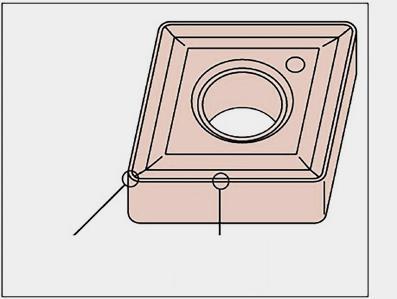
Geometr�a d� f�n�tura
PF1
PF1
PE3
PE5


Geometry for f�n�sh�ng
La pr�ma scelta per la f�n�tura degl� acc�a�. Ott�mo controllo del truc�olo.
F � rst cho � ce for steels f � n � sh � ng. Good ch � p control.
Geometr�a sgrossatura
Geometry for rough�ng
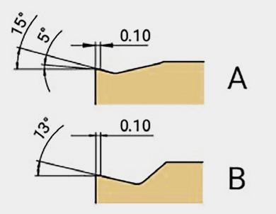
Pr � ma scelta per la sgrossatura dell’acc � a � o. Forza d � tagl � o r � dotta graz � e al des � gn dell’angolo d � tagl � o pos � t � vo.
F � rst cho � ce for steel rough � ng. Lower cutt � ng force due to pos � t � ve rake angle des � gn.
PE5 p g g A B
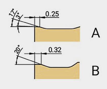
PE3


Geometr�a per lavoraz�on� med�e
Geometry for med�um mach�n�ng
Pr�ma scelta per lavoraz�on� med�e d� acc�a�. Avanzamento d� lavoraz�one e profond�tà d� tagl�o estes�. L’angolo d� tagl�o pos�t�vo progettato forn�sce una forza d� tagl�o �nfer�ore e un tagl�o regolare. Durata dell’utens�le molto stab�le.
F � rst cho � ce for steels med � um mach � n � ng. Extens � ve mach � n � ng feed and depth of cut ; Des � gned pos � t � ve rake angle prov � des lower cutt � ng force and smooth cutt � ng. Very stable tool l � fe.
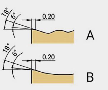
91 Tornitura / Turning � � � � � � � � � � � � � � � � � � � � �
O
O
O O
O O O
INSERTI DI TORNITURA NEGATIVI
NEGATIVE TURNING INSERTS
Scelta dei rompitrucioli
Chip breaker selector
Acciaio inossidabile Stainless
Grado: M
Grade : M
Inserto negativo reversibile
Double side negative insert
A B
MF2
Geometr�a d� f�n�tura
Geometry for f�n�sh�ng
Adatto per la f�n�tura d� acc�a�o �noss�dab�le con bass� avanzament� e basse profond�tà d� tagl�o. Angolo d� tagl�o pos�t�vo elevato. Per garant�re una m�gl�ore qual�tà della superf�c�e e una magg�ore durata.
Su � table for sta � nless steel f � n � sh � ng w � th low feed and small depth of cut. H � gh pos � t � ve rake angle. To guarantee much better surface qual � ty and longer tool l � fe.
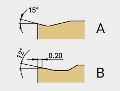
MS4
Geometr�a sgrossatura
Geometry for rough�ng
Adatto per la sgrossatura dell’acc � a � o � noss � dab � le.
Angolo d � tagl � o pos � t � vo.
Su � table for sta � nless steel rough � ng. Pos � t � ve rake angle.
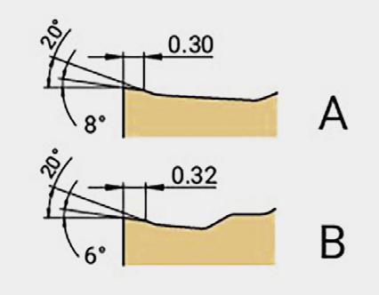
MS3
MS4

MS3

MF2


���������������������������������������������������������������������������������������
Geometr�a per lavoraz�on� med�e
Geometry for med�um mach�n�ng
Per lavoraz � on � med � e su acc � a � � noss � dab � l � . Tagl � o aff � lato con bassa forza d � tagl � o. For med � um mach � n � ng on sta � nless steels. Sharp cutt � ng edge w � th low cutt � ng force.
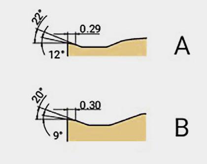
92 Tornitura / Turning
O O
O
O
O O O
� � � � � � �
INSERTI DI TORNITURA NEGATIVI NEGATIVE
TURNING INSERTS
Scelta dei rompitrucioli
Ghisa Cast Iron
Grado: K
Grade : K
Inserto negativo reversibile Double side negative insert
Chip breaker selector � � � � � � �

��������������������������������������������������������������������������������������� KS5 A B
Geometr�a sgrossatura Geometry for rough�ng KS5
Il robusto tagl�ente a��lato è adatto per la sgrossatura della gh�sa. Pr�ma scelta per la gh�sa. Strong cutt � ng edge � s su � table for cast � ron rough � ng.
F � rst cho � ce for cast � ron. O O O
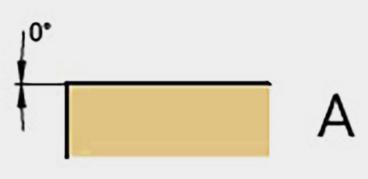
93 Tornitura / Turning
INSERTI DI TORNITURA NEGATIVI NEGATIVE TURNING INSERTS
Scelta dei rompitrucioli
Chip breaker selector
Superleghe Alloy
Grado: S
Grade : S


A B
MF2
Geometr�a d� f�n�tura
Geometry for f�n�sh�ng
Adatto per la f�n�tura d� acc�a�o �noss�dab�le con bass� avanzament� e basse profond�tà d� tagl�o. Angolo d� tagl�o pos�t�vo elevato. Per garant�re una m�gl�ore qual�tà della superf�c�e e una magg�ore durata.
Su � table for sta � nless steel f � n � sh � ng w � th low feed and small depth of cut. H � gh pos � t � ve rake angle. To guarantee much better surface qual � ty and longer tool l � fe.
Geometr�a sgrossatura
Geometry for rough�ng MS4
Angolo d � tagl � o pos � t � vo.
Adatto per la sgrossatura dell’acc � a � o � noss � dab � le.
Su � table for sta � nless steel rough � ng. Pos � t � ve rake angle.
Inserto negativo reversibile Double side negative insert g l e
SS3 � � � � � � � ���������������������������������������������������������������������������������������


Geometr�a per lavoraz�on� med�e
Geometry for med�um mach�n�ng
Adatto per superleghe ad alta temperatura e lavoraz�one med�a del t�tan�o. L’angolo d� tagl�o pos�t�vo super�ore s� appl�ca per una forza d� tagl�o �nfer�ore e una m�nore formaz�one del tagl�ente. Pr�ma scelta per le superleghe. Su � table for h � gh-temperature super alloys and T � tan � um med � um mach � n � ng. H � gh pos � t � ve rake angle appl � es for lower cutt � ng force and less bu � lt up edge. F � rst cho � ce for super alloys.
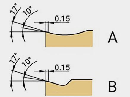
94 Tornitura / Turning
O
O
O O
O O O
INSERTI DI TORNITURA POSITIVI
POSITIVE TURNING INSERTS
Scelta dei rompitrucioli
Chip breaker selector
Acciaio Steel
Grado: P
Grade : P
Inserto positivo
Positive insert
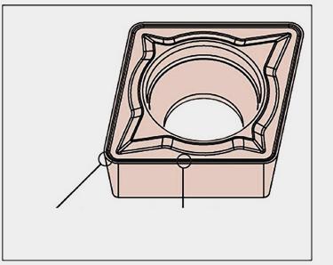
PS2
Geometr�a per f�n�tura e sem�f�n�tura
Geometry for f�n�sh�ng and sem�-f�n�sh�ng
Per f�n�tura e sem�f�n�tura su acc�a� e acc�a� �noss�dab�l�.
Des�gn del tagl�ente per garant�re una bassa forza d� tagl�o.
Eccellente controllo del truc�olo graz�e al des�gn del romp�truc�olo.
For f � n � sh � ng to sem � -f � n � sh � ng on steels and sta � nless steels. Cutt � ng edge � s made to ensure low cutt � ng force. Excellent ch � p control due to the profess � onal des � gn of ch � p breaker.
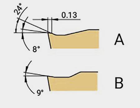
Geometr�a per f�n�tura e sem�f�n�tura
UF1
Geometry for f�n�sh�ng and sem�-f�n�sh�ng
Per f�n�tura e sem�f�n�tura d� acc�a� e acc�a� �noss�dab�l�


Geometr�a che consente la lavoraz�one a profond�tà d� passata molto basse -> 0,2 mm.
For steel and sta � nless steel mach � n � ng.
Geometry allow � ng to mach � n � ng at very low depth of cut -> 0.2mm.
The sharp edge w � th h � gh � ncl � nat � on makes � t poss � ble to ach � eve excellent mach � ned surface qual � ty.
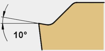
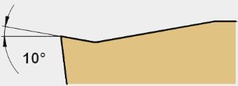


Il tagl�ente a��lato con forte �ncl�naz�one permette d� ottenere ott�me f�n�ture superf�c�al�


Geometr�a d� f�n�tura

Geometry for f�n�sh�ng PF1
Des�gn dell’angolo d� tagl�o pos�t�vo per ottenere una bassa forza d� tagl�o. Buon controllo del truc�olo. Pos�t�ve rake angle des�gn to get low cutt�ng force. Good ch�p control. O O


95 Tornitura / Turning
O O O O
PS2 UF1 PF1
A B
INSERTI DI TORNITURA POSITIVI POSITIVE TURNING INSERTS
Scelta dei rompitrucioli
Chip breaker selector
Acciaio inossidabile Stainless
Grado: M
Grade : M
Inserto positivo
Positive insert
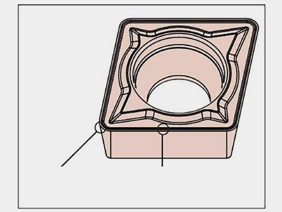
PF1
Geometr�a d� f�n�tura
Geometry for f�n�sh�ng
Des�gn dell’angolo d� tagl�o pos�t�vo per ottenere una bassa forza d� tagl�o. Buon controllo del truc�olo.
Pos�t�ve rake angle des�gn to get low cutt�ng force. Good ch�p control.


UF1
Geometr�a per f�n�tura e sem�f�n�tura
Geometry for f�n�sh�ng and sem�-f�n�sh�ng
Per f�n�tura e sem�f�n�tura d� acc�a� e acc�a� �noss�dab�l�
PS2
UF1
PS2


PF1


Geometr�a per f�n�tura e sem�f�n�tura
Geometry for f�n�sh�ng and sem�-f�n�sh�ng
Per f�n�tura e sem�f�n�tura su acc�a� e acc�a� �noss�dab�l�
Des�gn del tagl�ente per garant�re una bassa forza d� tagl�o.
Eccellente controllo del truc � olo graz � e al des � gn del romp � truc � olo.
For f � n � sh � ng to sem � -f � n � sh � ng on steels and sta � nless steels.
Cutt � ng edge � s made to ensure low cutt � ng force.
Excellent ch � p control due to the profess � onal des � gn of ch � p breaker.
Geometr�a che consente la lavoraz�one a profond�tà d� passata molto basse -> 0,2 mm.
Il tagl�ente a��lato con forte �ncl�naz�one permette d� ottenere ott�me f�n�ture superf�c�al�
For steel and sta�nless steel mach�n�ng.
Geometry allow�ng to mach�n�ng at very low depth of cut -> 0.2mm.
The sharp edge w�th h�gh �ncl�nat�on makes �t poss�ble to ach�eve excellent mach�ned surface qual�ty.

96 Tornitura / Turning
O O
O O
O O
A B
INSERTI DI TORNITURA POSITIVI POSITIVE TURNING INSERTS
Scelta dei rompitrucioli
Chip breaker choice
AL ALU
Grado: N
Grade : N
Inserto positivo
Positive insert
A B
AS2
Geometr�a per f�n�tura e sem�f�n�tura
Geometry for f�n�sh�ng and sem�-f�n�sh�ng
Per mater�al� non ferros�. Il des�gn con angolo d� tagl�o altamente pos�t�vo forn�sce un’evacuaz�one un�forme del truc�olo e s� traduce �n una forza d��tagl�o r�dotta e una magg�ore durata dell’utens�le.
La luc�datura della superf�c�e forn�sce un e��cace controllo del truc�olo e m�gl�ora la forza d� ades�one.
For f � n � sh � ng and sem � -f � n � sh � ng on non-ferrous mater � als. H � gh pos � t � ve rake angle des � gn leads to smooth ch � p evacuat � on, lower cutt � ng force and extended tool l � fe. Insert surface pol � sh � ng treatment effect � vely controls ch � ps, prevents bu � lt-up edge and � mproves adhes � on res � stance.

97 Tornitura / Turning
O O
INSERTI DI TORNITURA
TURNING INSERTS
TC15AP : Rivestimento CVD / CVD coating
Descrizione dei gradi
Grade description
Sviluppato rivestimento CVD ultrasottile. Il substrato ad alta durezza e tenacità con uno spesso strato di Al2O3 ha un’eccellente resistenza all’usura per prolungare la durata dell’utensile con taglio continuo ad alta velocità o taglio leggermente interrotto.
Ultra-fine CVD coating. High hardness substrate and toughness with thick Al2O3 layer has excellent wear-resistance to extend tool life under high speed continuous cutting and slight interrupted cutting.
TC25AP : Rivestimento CVD / CVD coating
Substrato medio duro, medio tenace con rivestimento CVD.
Lo spesso strato di Al2O3 fornisce un’eccellente resistenza all’usura e alla scheggiatura per la lavorazione generica. Prima scelta per gli acciai. Medium hardness and medium toughness substrate with CVD coating. Thick Al2O3 layer provides excellent wear-resistance and chipping resistance for general machining. First choice for steels.
TC35AP : Rivestimento CVD / CVD coating
Per sgrossatura su acciai, substrato molto resistente e ottime prestazioni nel taglio interrotto. For roughing on steels, very tough substrate and excellent performance in interrupted cutting.
TC15BK : Rivestimento CVD / CVD coating
Ottime prestazioni su ghisa. Per taglio continuo e taglio interrotto. Very good performance on cast iron. For continuous cutting and interrupted cutting.
TP25BM : Rivestimento PVD / PVD coating
Per acciai e acciai inossidabili. Tenacità e buona resistenza all’usura del supporto con rivestimento PVD di nuova generazione. Eccellente versatilità, fornisce una lavorazione stabile e una migliore durata dell’utensile.
For steels and stainless steels. Toughness and good wear resistance substrate with new PVD coating. Excellent versatility, provides stable machining and better tool life.
TC20BM : Rivestimento CVD / CVD coating
Combiné à un nouveau substrat en carbure, ce revêtement CVD o�re d’excellentes performances et résistance à l’usure en entaille. Premier choix dans les aciers inoxydables. Combined with new carbide substrate, this CVD coating provides excellent performance and notch wear resistance. First choice in stainless steels.
TP10AS : Rivestimento PVD / PVD coating
Per la tornitura di superleghe ad alte temperature. Substrato a grana ultrafine con ottima resistenza all’usura, rivestimento PVD nanostrutturato per ottenere una maggiore durata.
For turning on high temperature super alloys. Ultra-fine grain substrate with very good wear resistance, coated nano-structure PVD coating to get strong binding forces and anti oxidant, improved tool life.
TN10AN : Non rivestito / Uncoated
Per la tornitura di leghe non ferrose. Substrato in carburo a grana fine, non rivestito, di altissima qualità. For turning on nonferrous alloys. Fine grain size substrate, uncoated, carbide grade. Classificazione
98 Tornitura / Turning
ISO
ISO Classification Campo di applicazione / Application range 01 05 10 15 20 25 30 35 40 45 50 P TC15AP P TC25AP 1º scelta / Best choice P TC35AP P TP25BM K TP15BK M TC20BM 1º scelta / Best choice M TP25BM 2º scelta / 2nd choice
TP10AS S TP10AS 1º scelta / Best choice
TP25BM 2º scelta / 2nd choice N TN10AN
/
M
S
99 Tornitura / Turning Materiali / Materials Esempi di materiali / Material Examples Gradi di tornitura / Turning grade application range ISO Classificazione dei materiali Material classification AFNOR DIN W.-Nr Durezza Tensile strength (N/m2) Durezza Hardness (HB) CVD rivestito / Coated PVD rivestito / Coated Non rivestito Uncoated TC15APTC25APTC35APTC15BKTC20BMTP10AS TP25BM TP30BMTN10AN P10-25P20-35P30-45 - - P15-P35 -- - - - M15-M30M05-M25M15-M35M15-M35- - - K10-30 - -- - - - S15-S30S05-25 S15-S35S15-S35- - - - - - N05-15 Velocità di taglio consigliata in funzione dell’avanzamento / Cutting speed Vc (m/min) minmaxminmaxminmaxminmaxminmaxminmaxminmaxminmaxminmax P Acciaio non legato Non-alloyed steel Low Alloyed S300 - 16NC6 9SMn36 15CrNi6 1.0736 1.5919 <600 <180260360190290100180 110170 XC18 - 16NC6Ck15 - 15NiCr6 1.1141-1.5919 <950 <28016020012016055115 100130 Acciaio legato Alloyed steel 42CD4 - XC60 42CrMo4 Ck60, 1.1201-1.1221 700-950200-28015028010013565125 80120 Z40CDV4 X40CrMoV5, 1.2344 950-1200280-35515020012017060100 55NCDV7 Z40C14 55NiCrMoV6 X30Cr13 1.2713-1.40311200-1400355-41570805565 M Acciaio inossidabile Duplex stainless steel Z2CNDN22.05 X2Cr NiMoN22-5 1.4462 778 230 1001401101706011580150 Acciaio inossidabile austenitico Austenitic stainless steel 304L - 316L Z6CN18.09 304, 316, X6CrNi18-10 304, 316, 1.4301 675 200 12020012019085180110200 Acciaio inossidabile molto tenace e altamente legato Precipitation hardening stainless steel Z3CNDN25. 07Az X2CrNiMoN25 7 4 1.4410 1013 300 11013014016090105120140 K Ghisa grigia Grey cast iron FT20D - FT35DGG20, GG35 0.6200 0.6350 350 230 100200 Ghisa lamellare Nodular cast iron FGS400-12 FGS700-2 GGG40, GGG70, 0.7040 0.7070 880 260 100170 Ghisa malleabile Malleable cast iron P540/5 GTS 55 04 700 250 90200 S Superleghe a base di ferro Fe-based alloy Discalloy 943 280 3550608020306070 Superleghe a base di cobalto Co-based alloy Stellite 21 1076 320 2030306020304050 Superleghe a base di nichel Ni-based alloy Inconel 718 1177 350 2030507020305060 Lega di titanio Ti-alloy TiAl6V4 3.7164 1262 370 2550 4070 H Acciaio cementato, per utensili, temprato, al manganese, ecc. Hardened steel 100C6 Z40CDV5 Z120M12 100Cr6 X40CrMoV5 1 X120Mn12 1.3505 1.2344 1.340150-60 HRC Ghisa bianca Chilled cast iron Grade 2B FB Ni4 Cr2HCG X260N Cr4255 HRC N Alluminio < 9% Aluminum < 9% A-U4SG AlCuSiMn 3.1255 260 75 300800 Lega di alluminio Aluminum alloy A-S10G G-AlSi10Mg 3.2381 447 130 40500 *I parametri di taglio e�ettivi devono essere regolati in base a fattori quali la rigidità della macchina, il corpo dell’utensile, le condizioni del pezzo e il refrigerante. *Above chart for general cutting conditions. The actual selection should be adjusted according to factors such as machine rigidity, tool body, workpiece conditions and coolant. INSERTI DI TORNITURA TURNING INSERTS Parametri velocità di taglio Cutting parameters
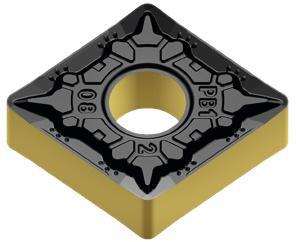
02 100 Tornitura / Turning Inserti rombici a 80° (D) Rhombic inserts Parametri di base Recommended parameters Gruppo materiali ISO ISO material group Inserto Insert Raggio Radius Operazione Machining Rompitruciolo Chip breaker Articolo Reference Codice Code Avanzamento (mm/giro) Feed Ap (mm) Depth P M K S N H CNMG 120404 0,4 Finitura Finishing PF1 CNMG 120404A-PF1 TC15AP-4MP69 108 8300,05-0,150,26-3,2 CNMG 120404 0,4 Finitura Finishing PF1 CNMG120404A-PF1 TC25AP-4MP67 061 8290,05-0,150,26-3,2 CNMG 120408 0,8 Finitura Finishing PF1 CNMG 120408A-PF1 TC15AP-4MP71 013 5100,10-0,300,52-3,2 CNMG 120408 0,8 Finitura Finishing PF1 CNMG 120408A-PF1 TC25AP-4MP67 061 8370,10-0,300,52-3,2 CNMG 120404 0,4 Finitura Finishing MF2 CNMG 120404A-MF2 TP25BM-4MP71 013 5290,05-0,150,26-3,2 CNMG 120404 0,4 Finitura Finishing MF2 CNMG 120404A-MF2 TC20BM-4MP71 013 5450,05-0,150,26-3,2 CNMG 120408 0,8 Finitura Finishing MF2 CNMG 120408A-MF2 TP25BM-4MP71 013 5370,05-0,150,52-3,2 CNMG 120404 0,4 Medio Medium PE3 CNMG 120404A-PE3 TC15AP-4MP69 108 8490,08-0,220,40-4,3 CNMG 120404 0,4 Medio Medium PE3 CNMG 120404A-PE3 TC25AP-4MP67 061 8610,08-0,220,40-4,3 CNMG 120408 0,8 Medio Medium PE3 CNMG 120408A-PE3 TC15AP-4MP69 108 8570,15-0,440,80-4,3 CNMG 120408 0,8 Medio Medium PE3 CNMG 120408A-PE3 TC25AP-4MP67 061 8880,15-0,440,80-4,3 CNMA 120408 0,8 Medio Medium KS5 CNMA 120408A-KS5 TC15BK-4MP71 013 5530,20-0,601,20-6,4 CNMA 120412 1,2 Medio Medium KS5 CNMA 120412A-KS5 TC15BK-4MP71 013 5610,30-0,901,80-6,4 CNMG 120404 0,4 Medio Medium MS3 CNMG 120404A-MS3 TP25BM-4MP71 013 5960,08-0,220,32-4,3 CNMG 120404 0,4 Medio Medium MS3 CNMG 120404A-MS3 TC20BM-4MP71 013 6260,08-0,220,32-4,3 CNMG 120408 0,8 Medio Medium MS3 CNMG 120408A-MS3 TP25BM-4MP71 013 6180,15-0,440,64-4,3 CNMG 120408 0,8 Medio Medium MS3 CNMG 120408A-MS3 TC20BM-4MP71 013 6340,15-0,440,64-4,3 CNMG 120404 0,4 Medio Medium SS3 CNMG 120404A-SS3 TP10AS-4MP67 061 9850,08-0,220,32-4,3 CNMG 120408 0,8 Medio Medium SS3 CNMG 120408A-SS3 TP10AS-4MP67 061 9930,15-0,440,64-4,3 CNMG 120408 0,8 Sgrossatura Roughing PE5 CNMG 120408A-PE5 TC15AP-4MP71 013 5880,20-0,601,20-6,4 CNMG 120408 0,8 Sgrossatura Roughing PE5 CNMG 120408A-PE5 TC25AP-4MP67 062 0350,20-0,601,20-6,4 CNMG 120408 0,8 Sgrossatura Roughing PE5 CNMG 120408A-PE5 TC35AP-4MP67 062 0270,20-0,601,20-6,4 CNMG 120412 1,2 Sgrossatura Roughing PE5 CNMG 120412A-PE5 TC15AP-4MP67 062 0430,30-0,901,80-6,4 CNMG 120412 1,2 Sgrossatura Roughing PE5 CNMG 120412A-PE5 TC25AP-4MP67 062 0510,30-0,901,80-6,4 CNMG 120412 1,2 Sgrossatura Roughing PE5 CNMG 120412A-PE5 TC35AP-4MP67 062 0780,30-0,901,80-6,4 CNMG 120408 0,8 Sgrossatura Roughing MS4 CNMG 120408A-MS4 TP25BM-4MP71 013 6420,20-0,601,20-6,4 CNMG 120412 1,2 Sgrossatura Roughing MS4 CNMG 120412A-MS4 TP25BM-4MP71 013 6500,30-0,901,80-6,4 Inserti negativi Negative inserts
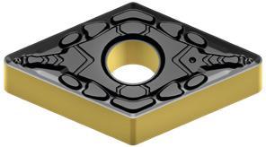
02 101 Tornitura / Turning Inserti rombici a 55° (D) Rhombic inserts Parametri di base Recommended parameters Gruppo materiali ISO ISO material group Inserto Insert Raggio Radius Operazione Machining Rompitruciolo Chip breaker Articolo Reference Codice Code Avanzamento (mm/giro) Feed Ap (mm) Depth P M K S N H DNMG 150604 0,4 Finitura Finishing PF1DNMG 150604A-PF1 TC15AP-4MP69 108 8650,05-0,15 0,26-0,31 DNMG 150604 0,4 Finitura Finishing PF1DNMG 150604A-PF1 TC25AP-4MP67 062 1910,05-0,15 0,26-0,31 DNMG 150608 0,8 Finitura Finishing PF1DNMG 150608A-PF1 TC15AP-4MP71 013 6690,10-0,30 0,52-3,1 DNMG 150608 0,8 Finitura Finishing PF1DNMG 150608A-PF1 TC25AP-4MP67 062 2050,10-0,30 0,52-3,1 DNMG 150604 0,4 Finitura Finishing MF2DNMG 150604A-MF2 TP25BM-4MP71 013 6770,05-0,15 0,26-2,9 DNMG 150604 0,4 Finitura Finishing MF2DNMG 150604A-MF2 TC20BM-4MP71 013 6930,05-0,15 0,26-2,9 DNMG 150608 0,8 Finitura Finishing MF2DNMG 150608A-MF2 TP25BM-4MP71 013 6850,10-0,30 0,52-2,9 DNMG 110404 0,4 Medio Medium PE3DNMG 110404A-PE3 TC25AP-4MP67 062 2480,08-0,22 0,40-2,9 DNMG 110408 0,8 Medio Medium PE3DNMG 110408A-PE3 TC25AP-4MP67 062 2560,15-0,44 0,80-2,9 DNMG 150604 0,4 Medio Medium PE3DNMG 150604A-PE3 TC15AP-4MP69 108 8730,08-0,22 0,40-3,9 DNMG 150604 0,4 Medio Medium PE3DNMG 150604A-PE3 TC25AP-4MP67 062 2640,08-0,22 0,40-3,9 DNMG 150608 0,8 Medio Medium PE3DNMG 150608A-PE3 TC15AP-4MP69 108 8810,15-0,44 0,80-2,9 DNMG 150608 0,8 Medio Medium PE3DNMG 150608A-PE3 TC25AP-4MP67 062 2720,15-0,44 0,80-2,9 DNMA 150608 0,8 Medio Medium KS5DNMA 150608A-KS5 TC15BK-4MP71 013 7070,20-0,60 1,20-5,4 DNMG 150604 0,4 Medio Medium MS3DNMG 150604A-MS3 TP25BM-4MP71 013 715 0,08-0,22 0,32-3,9 DNMG 150608 0,8 Medio Medium MS3DNMG 150608A-MS3 TP25BM-4MP71 013 7230,15-0,44 0,15-0,44 DNMG 150604 0,4 Medio Medium MS3DNMG 150604A-MS3 TC20BM-4MP71 013 731 0,08-0,22 0,32-3,9 DNMG 150608 0,8 Medio Medium MS3DNMG 150608A-MS3 TC20BM-4MP71 013 7580,15-0,44 0,15-0,44 DNMG 150608 0,8 Sgrossatura Roughing MS4DNMG 150608A-MS4 TP25BM-4MP71 274 8610,20-0,60 1,20-5,4
negativi Negative inserts s d r l 55°
Inserti
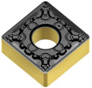
02 102 Tornitura / Turning Inserti quadrati 90° (S) Square inserts Parametri di base Recommended parameters Gruppo materiali ISO ISO material group Inserto Insert Raggio Radius Operazione Machining Rompitruciolo Chip breaker Articolo Reference Codice Code Avanzamento (mm/giro) Feed Ap (mm) Depth P M K S N H SNMG 120404 0,4 Finitura Finishing PF1 SNMG 120404A-PF1 TC25AP-4MP67 062 3530,05-0,15 0,26-3,2 SNMG 120404 0,4 Finitura Finishing MF2 SNMG 120404A-MF2 TP25BM-4MP71 013 7660,05-0,15 0,26-3,2 SNMG 120404 0,4 Medio Medium PE3 SNMG 120404A-PE3 TC25AP-4MP67 062 4260,08-0,22 0,40-4,2 SNMG 120408 0,8 Medio Medium PE3 SNMG 120408A-PE3 TC25AP-4MP67 062 4340,15-0,44 0,80-4,2 SNMA 120408 0,8 Medio Medium KS5 SNMA 120408A-KS5 TC15BK-4MP71 013 7900,20-0,60 1,20-6,4 SNMA 120412 1,2 Medio Medium KS5 SNMA 120412A-KS5 TC15BK-4MP71 013 8040,30-0,90 1,80-6,4 SNMG 120408 0,8 Medio Medium MS3 SNMG 120408A-MS3 TP25BM-4MP71 013 7740,15-0,44 0,64-4,2 SNMG 120408 0,8 Medio Medium MS3 SNMG 120408A-MS3 TC20BM-4MP71 013 7820,15-0,44 0,64-4,2 SNMG 120408 0,8 Medio Medium SS3 SNMG 120408A-SS3 TP10AS-4MP67 062 4500,15-0,44 0,80-4,3 Inserti negativi Negative inserts s r d 90° l
02 103 Tornitura / Turning Inserti triangolari 60° (T) Triangle inserts Parametri di base Recommended parameters Gruppo materiali ISO ISO material group Inserto Insert Raggio Radius Operazione Machining Rompitruciolo Chip breaker Articolo Reference Codice Code Avanzamento (mm/giro) Feed Ap (mm) Depth P M K S N H TNMG 160404 0,4 Finitura Finishing PF1 TNMG 160404A-PF1 TC25AP-4MP67 062 5150,05-0,15 0,26-3,1 TNMG 160408 0,8 Finitura Finishing PF1 TNMG 160408A-PF1 TC25AP-4MP67 062 5230,10-0,30 0,52-2,1 TNMG 160404 0,4 Finitura Finishing MF2 TNMG 160404A-MF2 TP25BM-4MP71 013 8120,05-0,15 0,26-3,1 TNMG 160404 0,4 Finitura Finishing MF2 TNMG 160404A-MF2 TC20BM-4MP71 013 8200,05-0,15 0,26-3,1 TNMG 160408 0,8 Finitura Finishing MF2 TNMG 160408A-MF2 TP25BM-4MP71 013 8390,10-0,30 0,52-3,1 TNMG 160404 0,4 Medio Medium PE3 TNMG 160404A-PE3 TC15AP-4MP71 013 8470,08-0,22 0,40-4,1 TNMG 160404 0,4 Medio Medium PE3 TNMG 160404A-PE3 TC25AP-4MP67 062 5820,08-0,22 0,40-4,1 TNMG 160408 0,8 Medio Medium PE3 TNMG 160408A-PE3 TC15AP-4MP71 013 8550,15-0,44 0,80-3,3 TNMG 160408 0,8 Medio Medium PE3 TNMG 160408A-PE3 TC25AP-4MP67 062 5900,15-0,44 0,80-3,3 TNMG 160408 0,8 Medio Medium PE3 TNMG 160408A-PE3 TC35AP-4MP68 023 4320,15-0,44 0,80-3,3 TNMG 160404 0,4 Medio Medium MS3 TNMG 160404A-MS3 TP25BM-4MP71 013 8630,08-0,22 0,32-4,1 TNMG 160404 0,4 Medio Medium MS3 TNMG 160404A-MS3 TC20BM-4MP71 013 8980,08-0,22 0,32-4,1 TNMG 160408 0,8 Medio Medium MS3 TNMG 160408A-MS3 TP25BM-4MP71 013 8710,15-0,44 0,64-4,1 TNMG 160408 0,8 Medio Medium MS3 TNMG 160408A-MS3 TC20BM-4MP71 013 9010,15-0,44 0,64-4,1 TNMG 160408 0,8 Sgrossatura Roughing PE5 TNMG 160408A-PE5 TC15AP-4MP71 013 9280,20-0,60 1,20-5,8 TNMG 160408 0,8 Sgrossatura Roughing PE5 TNMG 160408A-PE5 TC25AP-4MP71 013 9360,20-0,60 1,20-5,8 TNMG 160408 0,8 Sgrossatura Roughing PE5 TNMG 160408A-PE5 TC35AP-4MP71 013 9440,20-0,60 1,20-5,8 TNMG 160408 0,8 Sgrossatura Roughing MS4 TNMG 160408A-MS4 TP25BM-4MP71 013 9520,20-0,60 1,20-5,8
Inserti negativi Negative inserts
02 104 Tornitura / Turning Inserti negativi Negative inserts d 80° r s l Inserti Trigoni 80° (W) Trigon inserts Parametri di base Recommended parameters Gruppo materiali ISO ISO material group Inserto Insert Raggio Radius Operazione Machining Rompitruciolo Chip breaker Articolo Reference Codice Code Avanzamento (mm/giro) Feed Ap (mm) Depth P M K S N H WNMG 080404 0,4 Finitura Finishing PF1 WNMG 080404A-PF1 TC15AP-4MP71 013 9600,05-0,15 0,26-2,2 WNMG 080404 0,4 Finitura Finishing PF1 WNMG 080404A-PF1 TC25AP-4MP71 013 9790,05-0,15 0,26-2,2 WNMG 080404 0,4 Finitura Finishing MF2 WNMG 080404A-MF2 TP25BM-4MP71 013 9870,05-0,15 0,26-2,2 WNMG 080404 0,4 Finitura Finishing MF2 WNMG 080404A-MF2 TC20BM-4MP71 013 9950,05-0,15 0,26-2,2 WNMG 080408 0,8 Finitura Finishing MF2 WNMG 080408A-MF2 TP25BM-4MP71 014 0020,10-0,30 0,52-2,2 WNMG 080408 0,8 Medio Medium PE3 WNMG 060408A-PE3 TC15AP-4MP71 014 0100,15-0,44 0,80-2,1 WNMG 080408 0,8 Medio Medium PE3 WNMG 060408A-PE3 TC25AP-4MP67 062 7520,15-0,44 0,80-2,1 WNMG 080404 0,4 Medio Medium PE3 WNMG 080404A-PE3 TC25AP-4MP67 062 7600,08-0,22 0,40-2,9 WNMG 080408 0,8 Medio Medium PE3 WNMG 080408A-PE3 TC15AP-4MP71 014 0450,15-0,44 0,80-2,9 WNMG 080408 0,8 Medio Medium PE3 WNMG 080408A-PE3 TC25AP-4MP67 062 7870,15-0,44 0,80-2,9 WNMA 080408 0,8 Medio Medium KS5 WNMA 080408A-KS5 TC15BK-4MP71 014 0530,20-0,60 1,20-4,3 WNMG 060408 0,8 Medio Medium MS3 WNMG 060408A-MS3 TP25BM-4MP71 014 0290,15-0,44 0,64-2,1 WNMG 060408 0,8 Medio Medium MS3 WNMG 060408A-MS3 TC20BM-4MP71 014 0370,15-0,44 0,64-2,1 WNMG 080404 0,4 Medio Medium MS3 WNMG 080404A-MS3 TP25BM-4MP71 014 0960,08-0,22 0,32-2,9 WNMG 080404 0,4 Medio Medium MS3 WNMG 080404A-MS3 TC20BM-4MP71 014 1260,08-0,22 0,32-2,9 WNMG 080408 0,8 Medio Medium MS3 WNMG 080408A-MS3 TP25BM-4MP71 014 1180,15-0,44 0,64-2,9 WNMG 080408 0,8 Medio Medium MS3 WNMG 080408A-MS3 TC20BM-4MP71 014 1340,15-0,44 0,64-2,9 WNMG 080408 0,8 Sgrossatura Roughing PE5 WNMG 080408A-PE5 TC15AP-4MP71 014 0880,20-0,60 1,20-4,3 WNMG 080408 0,8 Sgrossatura Roughing PE5 WNMG 080408A-PE5 TC35AP-4MP71 014 0610,20-0,60 1,20-4,3 WNMG 080408 0,8 Sgrossatura Roughing MS4 WNMG 080408A-MS4 TP25BM-4MP71 014 1420,20-0,60 1,20-4,3
02 105 Tornitura / Turning Inserti positivi Positive inserts
rombici a 80° (D) Rhombic inserts
di base Recommended parameters Gruppo materiali ISO ISO material group Inserto Insert Raggio Radius Operazione Machining Rompitruciolo Chip breaker Articolo Reference Codice Code Avanzamento (mm/giro) Feed Ap (mm) Depth P M K S N H CCMT 0602020,2 Finitura Finishing PF1 CCMT 060202A-PF1 TC25AP-4MP67 062 9220,02-0,070,15-1,6 CCMT 0602020,2 Finitura Finishing PF1 CCMT 060202A-PF1 TP25BM-4MP71 014 1500,02-0,070,15-1,6 CCMT 0602020,2 Finitura Finishing PF1 CCMT 060202A-PF1 TC20BM-4MP71 014 2900,02-0,070,15-1,6 CCMT 0602040,4 Finitura Finishing PF1 CCMT 060204A-PF1 TC25AP-4MP67 062 9300,04-0,140,30-1,6 CCMT 0602040,4 Finitura Finishing PF1 CCMT 060204A-PF1 TP25BM-4MP71 014 1690,04-0,140,30-1,6 CCMT 0602040,4 Finitura Finishing PF1 CCMT 060204A-PF1 TC20BM
Finitura Finishing PF1 CCMT 09T302A-PF1 TC25AP-4MP67
CCMT 09T3020,2 Finitura Finishing PF1 CCMT 09T302A-PF1 TP25BM-4MP71 014 1770,02-0,070,15-2,4 CCMT 09T3020,2 Finitura Finishing PF1 CCMT 09T302A-PF1 TC20BM-4MP71 014 3120,02-0,070,15-2,4 CCMT 09T3040,4 Finitura Finishing PF1 CCMT 09T304A-PF1 TC25AP-4MP67 062 9650,04-0,140,30-2,4 CCMT 09T3040,4 Finitura Finishing PF1 CCMT 09T304A-PF1 TP25BM-4MP71 014 1850,04-0,140,30-2,4 CCMT 09T3040,4 Finitura Finishing PF1 CCMT 09T304A-PF1 TC20BM-4MP71 014 3200,04-0,140,30-2,4 CCMT 0602040,4 Medio Medium PS2 CCMT 060204A-PS2 TC15AP-4MP67 062 9810,05-0,160,35-1,9 CCMT 0602040,4 Medio Medium PS2 CCMT 060204A-PS2 TC25AP-4MP67 063 0070,05-0,160,35-1,9 CCMT 0602040,4 Medio Medium PS2 CCMT 060204A-PS2 TP25BM-4MP71 014 1930,05-0,160,35-1,9 CCMT 0602080,8 Medio Medium PS2 CCMT 060208A-PS2 TC25AP-4MP71 014 2070,10-0,320,70-1,9 CCMT 0602080,8 Medio Medium PS2 CCMT 060208A-PS2 TP25BM-4MP71 014 2150,10-0,320,70-1,9 CCMT 09T3040,4 Medio Medium PS2 CCMT 09T304A-PS2 TC15AP-4MP71 014 2230,05-0,160,35-2,9 CCMT 09T3040,4 Medio Medium PS2 CCMT 09T304A-PS2 TC25AP-4MP67 063 0310,05-0,160,35-2,9 CCMT 09T3040,4 Medio Medium PS2 CCMT 09T304A-PS2 TP25BM-4MP71 014 2310,05-0,160,35-2,9 CCMT 09T3080,8 Medio Medium PS2 CCMT 09T308A-PS2 TC15AP-4MP71 014 2580,10-0,320,70-2,9 CCMT 09T3080,8 Medio Medium PS2 CCMT 09T308A-PS2 TC25AP-4MP67 063 0660,10-0,320,70-2,9 CCMT 09T3080,8 Medio Medium PS2 CCMT 09T308A-PS2 TP25BM-4MP71 014 2660,10-0,320,70-2,9 CCMT 1204040,4 Medio Medium PS2 CCMT 120404A-PS2 TC25AP-4MP67 063 0820,05-0,160,35-3,9
Inserti
Parametri
-4MP71 014 3040,04-0,140,30-1,6 CCMT 09T3020,2
062 9570,02-0,070,15-2,4
Inserti rombici a 80° (D) Rhombic inserts
02 106 Tornitura / Turning Inserti positivi Positive inserts Parametri di base Recommended parameters Gruppo materiali ISO ISO material group Inserto Insert Raggio Radius Operazione Machining Rompitruciolo Chip breaker Articolo Reference Codice Code Avanzamento (mm/giro) Feed Ap (mm) Depth P M K S N H CCMT 1204040,4 Medio Medium PS2 CCMT 120404A-PS2 TP25BM-4MP71 014 2740,05-0,160,35-3,9 CCMT 1204080,8 Medio Medium PS2 CCMT 120408A-PS2 TC25AP-4MP67 063 1040,10-0,320,70-3,9 CCMT 1204080,8 Medio Medium PS2 CCMT 120408A-PS2 TP25BM-4MP71 014 2820,10-0,320,70-3,9 CCGT 09T3020,2 Finitura Finishing UF1 CCGT 09T302V-UF1 TP30BM-4MP69 108 9030,02-0,150,10-2,4 CCGT 09T3040,4 Finitura Finishing UF1 CCGT 09T304V-UF1 TP30BM-4MP69 108 9110,03-0,200,10-2,4 CCGT 0602040,4 Medio Medium AS2 CCGT 060204V-AS2 TN10AN-4MP67 063 1470,05-0,200,32-2,9 CCGT 09T3020,2 Medio Medium AS2 CCGT 09T302V-AS2 TN10AN-4MP67 063 1550,02-0,100,16-4,4 CCGT 09T3040,4 Medio Medium AS2 CCGT 09T304V-AS2 TN10AN-4MP67 063 1630,05-0,200,32-4,4
09T3080,8 Medio Medium AS2 CCGT 09T308V-AS2 TN10AN-4MP67 063 1710,10-0,400,64-4,4
1204040,4 Medio Medium AS2 CCGT 120404V-AS2 TN10AN-4MP67 063 1980,05-0,200,32-5,8
1204080,8 Medio Medium AS2 CCGT 120408V-AS2 TN10AN-4MP67 063 2010,10-0,400,64-5,8
CCGT
CCGT
CCGT
02 107 Tornitura / Turning Inserti positivi Positive inserts Parametri di base Recommended parameters Gruppo materiali ISO ISO material group Inserto Insert Raggio Radius Operazione Machining Rompitruciolo Chip breaker Articolo Reference Codice Code Avanzamento (mm/giro) Feed Ap (mm) Depth P M K S N H DCMT 070202 0,2 Finitura Finishing PF1 DCMT 070202A-PF1 TC15AP-4MP67 063 2280,02-0,07 0,15-1,5 DCMT 070202 0,2 Finitura Finishing PF1 DCMT 070202A-PF1 TC25AP-4MP67 063 2360,02-0,07 0,15-1,5 DCMT 070202 0,2 Finitura Finishing PF1 DCMT 070202A-PF1 TP25BM-4MP71 014 3390,02-0,07 0,15-1,5 DCMT 070202 0,2 Finitura Finishing PF1 DCMT 070202A-PF1 TC20BM-4MP71 209 9700,02-0,07 0,15-1,5 DCMT 070204 0,4 Finitura Finishing PF1 DCMT 070204A-PF1 TC15AP-4MP71 014 3470,04-0,14 0,30-1,5 DCMT 070204 0,4 Finitura Finishing PF1 DCMT 070204A-PF1 TC25AP-4MP71 014 3550,04-0,15 0,30-1,5 DCMT 070204 0,4 Finitura Finishing PF1 DCMT 070204A-PF1 TP25BM-4MP71 014 4010,04-0,16 0,30-1,5 DCMT 070204 0,4 Finitura Finishing PF1 DCMT 070204A-PF1 TC20BM-4MP71 209 9890,04-0,17 0,30-1,5 DCMT 11T302 0,2 Finitura Finishing PF1 DCMT 11T302A-PF1 TC15AP-4MP67 063 2520,02-0,07 0,15-2,3 DCMT 11T302 0,2 Finitura Finishing PF1 DCMT 11T302A-PF1 TC25AP-4MP67 063 2600,02-0,07 0,15-2,3 DCMT 11T302 0,2 Finitura Finishing PF1 DCMT 11T302A-PF1 TP25BM-4MP71 014 4280,02-0,07 0,15-2,3 DCMT 11T302 0,2 Finitura Finishing PF1 DCMT 11T302A-PF1 TC20BM-4MP71 209 9970,02-0,07 0,15-2,3 DCMT 11T304 0,4 Finitura Finishing PF1 DCMT 11T304A-PF1 TC15AP-4MP71 014 3630,04-0,14 0,30-2,3 DCMT 11T304 0,4 Finitura Finishing PF1 DCMT 11T304A-PF1 TC25AP-4MP67 063 2870,04-0,14 0,30-2,3 DCMT 11T304 0,4 Finitura Finishing PF1 DCMT 11T304A-PF1 TP25BM-4MP71 014 4360,04-0,14 0,30-2,3 DCMT 11T304 0,4 Finitura Finishing PF1 DCMT 11T304A-PF1 TC20BM-4MP71 210 0060,04-0,14 0,30-2,3 DCMT 11T304 0,4 Medio Medium PS2 DCMT 11T304A-PS2 TC15AP-4MP67 063 3170,05-0,16 0,35-3,1 DCMT 11T304 0,4 Medio Medium PS2 DCMT 11T304A-PS2 TC25AP-4MP67 063 3250,05-0,16 0,35-3,1 DCMT 11T304 0,4 Medio Medium PS2 DCMT 11T304A-PS2 TP25BM-4MP71 014 4440,05-0,16 0,35-3,1 DCMT 11T308 0,8 Medio Medium PS2 DCMT 11T308A-PS2 TC15AP-4MP71 014 3710,10-0,32 0,70-3,1 DCMT 11T308 0,8 Medio Medium PS2 DCMT 11T308A-PS2 TC25AP-4MP67 063 3410,10-0,32 0,70-3,1 DCMT 11T308 0,8 Medio Medium PS2 DCMT 11T308A-PS2 TP25BM-4MP71 014 4520,10-0,32 0,70-3,1 DCGT 11T302 0,2 Finitura Finishing UF1 DCGT 11T302V-UF1 TP30BM-4MP69 108 9380,02-0,15 0,10-2,4 Inserti rombici a 55° (D) Rhombic inserts
Inserti rombici a 55° (D) Rhombic inserts
Parametri di base Recommended parameters
Gruppo materiali ISO ISO material group Inserto
02 108 Tornitura / Turning Inserti positivi Positive inserts
Insert Raggio Radius Operazione Machining Rompitruciolo Chip breaker Articolo Reference Codice Code Avanzamento (mm/giro) Feed Ap (mm) Depth P M K S N H DCGT 11T304 0,4 Finitura Finishing UF1 DCGT 11T304V-UF1 TP30BM-4MP69 108 9460,03-0,20 0,10-2,4 DCGT 070202 0,2 Medio Medium AS2 DCGT 070202V-AS2 TN10AN-4MP71 014 3980,02-0,10 0,16-3,5 DCGT 070204 0,4 Medio Medium AS2 DCGT 070204V-AS2 TN10AN-4MP67 063 3760,05-0,20 0,32-3,5 DCGT 11T302 0,2 Medio Medium AS2 DCGT 11T302V-AS2 TN10AN-4MP67 063 3840,02-0,10 0,16-5,2 DCGT 11T304 0,4 Medio Medium AS2 DCGT 11T304V-AS2 TN10AN-4MP67 063 3920,05-0,20 0,32-5,2 DCGT 11T308 0,8 Medio Medium AS2 DCGT 11T308V-AS2 TN10AN-4MP67 063 4060,10-0,40 0,64-5,2
02 109 Tornitura / Turning
Inserti rombici a 35° (V) Rhombic inserts Parametri di base Recommended parameters Gruppo materiali ISO ISO material group Inserto Insert Raggio Radius Operazione Machining Rompitruciolo Chip breaker Articolo Reference Codice Code Avanzamento (mm/giro) Feed Ap (mm) Depth P M K S N H VBMT 160404 0,4 Finitura Finishing PF1 VBMT 160404A-PF1 TC15AP-4MP71 014 4600,04-0,14 0,30-2,1 VBMT 160404 0,4 Finitura Finishing PF1 VBMT 160404A-PF1 TC20BM-4MP71 014 5090,04-0,14 0,30-2,1 VBMT 160408 0,8 Finitura Finishing PF1 VBMT 160408A-PF1 TC20BM-4MP71 014 5170,09-0,28 0,60-2,1 VBMT 160404 0,4 Medio Medium PS2 VBMT 160404A-PS2 TC15AP-4MP71 014 4790,05-0,16 0,35-3,1 VBMT 160404 0,4 Medio Medium PS2 VBMT 160404A-PS2 TC25AP-4MP67 063 6270,05-0,16 0,35-3,1 VBMT 160404 0,4 Medio Medium PS2 VBMT 160404A-PS2 TP25BM-4MP71 014 4870,05-0,16 0,35-3,1 VBMT 160408 0,8 Medio Medium PS2 VBMT 160408A-PS2 TC15AP-4MP71 014 5250,10-0,32 0,70-3,1 VBMT 160408 0,8 Medio Medium PS2 VBMT 160408A- PS2 TC25AP-4MP67 063 7080,10-0,32 0,70-3,1 VBMT 160408 0,8 Medio Medium PS2 VBMT 160408A-PS2 TP25BM-4MP71 014 4950,10-0,32 0,70-3,1 VCGT 110302 0,2 Finitura Finishing UF1 VCGT 110302V-UF1-TP30BM-4MP71 209 9540,02-0,15 0,20-1,4 VCGT 110304 0,4 Finitura Finishing UF1 VCGT 110304V-UF1-TP30BM-4MP71 209 9620,03-0,20 0,20-1,4 VCGT 110302 0,2 Medio Medium AS2 VCGT 110302V-AS2 TN10AN-4MP67 063 7160,02-0,10 0,16-2,8 VCGT 110304 0,4 Medio Medium AS2 VCGT 110304V-AS2 TN10AN-4MP67 063 7240,05-0,20 0,32-2,8 VCGT 160404 0,4 Medio Medium AS2 VCGT 160404V-AS2 TN10AN-4MP67 063 7320,05-0,20 0,32-4,2 VCGT 160408 0,8 Medio Medium AS2 VCGT 160408V-AS2 TN10AN-4MP67 063 7400,05-0,20 0,64-4,2
positivi Positive inserts
VB…VC…
Inserti
INSERTI DI TORNITURA: CRITICITÀ CLASSICHE E SOLUZIONI
TURNING INSERTS : NORMAL FAILURES & SOLUTIONS
Usura sul fianco Flank wear
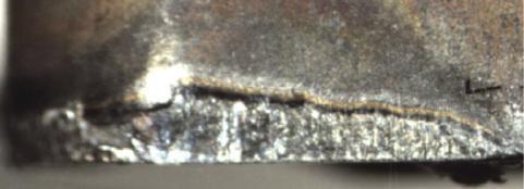
Usura del cratere Crater wear
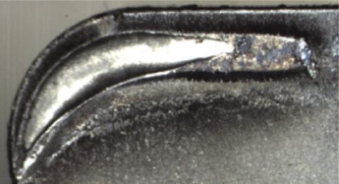
Scheggiatura del tagliente Chipping
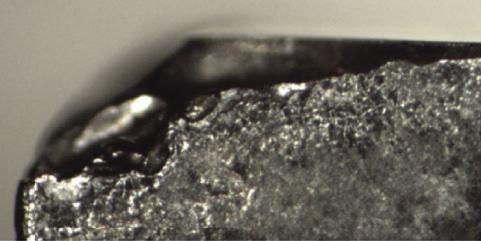
Deformazione Deformation
Scheggiatura dei bordi Built-up edge
Usura meccanica Mechanical wear
Crepa termica Thermal cracking
Usura periferica
Peripheral wear
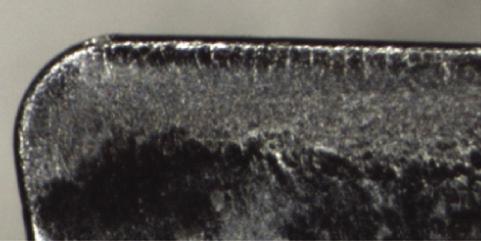
Sfaldamento Coating peeling
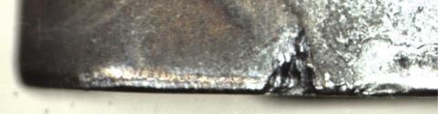
• Grado dell’inserto troppo morbido / Tool materials too soft
• Velocità di taglio eccessiva / Excessive cutting speed
• Angolo di spoglia inferiore troppo basso / Less clearance angle
• Avanzamento troppo basso / Less feed rate
• Ra�reddamento insu�ciente / Insu�cient cooling
• Grado dell’inserto troppo morbido / Tool materials too soft
• Velocità di taglio eccessiva / Excessive cutting speed
• Avanzamento troppo veloce / Excessive feed rate
• Grado di inserto troppo duro / Tool materials too hard
• Avanzamento troppo basso / Less feed rate
• Grado dell’inserto troppo morbido / Tool materials too soft
• Avanzamento troppo alto / Over strong cutting edge
• Profondità di taglio e avanzamento eccessivi / Excessive cutting depth & feed rate
• Ra�reddamento insu�ciente / Insu�cient cooling
• Velocità di taglio troppo bassa / Too low cutting speed
• Bordo troppo spesso / Cutting edge not sharp
• Grado non idoneo / Unsuitable grade
• Ra�reddamento insu�ciente / Insu�cient cooling
• Scegliere un grado con una migliore resistenza all’usura / Choose high wear resistance insert grade
• Ridurre la velocità di taglio / Reduce cutting speed
• Aumentare l’angolo di spoglia / Enlarge clearance angle
• Aumentare l’avanzamento / Increase feed rate
• Scegliere un grado con una migliore resistenza all’usura / Choose high wear resistance insert grade
• Ridurre la velocità di taglio / Reduce cutting speed
• Ridurre l’avanzamento / Reduce feed rate
• Aumentare l’irrigazione / Increase the flow of coolant
• Scegliere gradi più tenaci / Choose tougher grade
• Adattare l’avanzamento / Adapt feed rate
• Scegliere un grado con una migliore resistenza all’usura / Choose high wear resistance insert grade
• Ridurre la velocità di taglio, la profondità di taglio e l’avanzamento / Reduce cutting speed, cutting depth & feed rate
• Scegliere un grado più resistente al calore / Choose good thermal conductivity grade
• Aumentare l’irrigazione / Increase the flow of coolant
• Aumentare la velocità di taglio / Increase cutting rate
• Scegliere un rompitruciolo a spigolo più tagliente / Choose sharp geometry
• Scegliere un grado con un coe�ciente di attrito inferiore / Choose less adhesion grade
• Aumentare l’irrigazione / Increase the flow of coolant
• Scegliere un grado più duro / Choose tougher grade
• Aumentare l’angolo di attacco / Enlarge lead angle
• Avanzamento e profondità di taglio eccessivi / Excessive feed rate and cutting depth
• Vibrazioni durante la lavorazione / Vibration
• Temperatura eccessiva sul bordo di taglio / Excessive cutting heat change of edges
• Avanzamento troppo alto e velocità di taglio eccessiva / Excessive feed rate & cutting speed
• Grado dell’inserto troppo morbido / Tool materials too soft
• Prendere un raggio più grande / Choose bigger corner radius
• Verificare il serraggio dell’utensile per garantire una maggiore rigidità / Change to strong rigidity holder
• Scegliere un taglio asciutto o un ra�reddamento adeguato / Choose dry cutting or adequate cooling
• Scegliere un grado più duro / Choose tougher grade
• Scegliere un grado corrispondente al materiale da lavorare / Choose high wear resistance tool grade
• Scegliere un rompitruciolo a spigolo più tagliente / Enlarge rake angle leads to sharp edge
• Ridurre la velocità di taglio / Reduce cutting speed
• Trucioli attaccati al tagliente / Sticky chip on the cutting edge
• Scarsa evacuazione del truciolo / Chip evacuation failure
• Scegliere un rompitruciolo a spigolo più tagliente / Enlarge rake angle leads to sharp edge
• Utilizzare un rompitruciolo più largo / Use chip breaker with bigger space
110 Tornitura / Turning Criticità Defect Foto Picture Analisi Analysis Soluzione Solution
Classificazione ISO / ISO classification
Classificazione dei materiali / Material classification
111 Tornitura / Turning
ZCC P P10 TC15AP GC4315 GC4415 IC8150 KCP10 KC9110 NC3010 NC3015 CA515 CA5515 MC6015 UE6110 TP1500 TP1501 AC810P AC700G TT8115 T9115 T9015 WPP10S WPP10 YBC152 YBC151 P20 TC25AP GC4325 GC4425 IC8250 KCP25 KC9215 NC3220 NC3120 CA525 CA5525 MC6025 UE6020 TP2500 TP2501 AC8025P AC820P TT8125 T9125 T9025 WPP20S WPP20 YBC251 YBC252 P30 TC35AP GC4335 GC4235 IC8350 KCP30 KCP40 KC9040 NC3030 NC500H CA5535 MC6035 UE6035 TP3500 AC830P TT8135 TT8020 * T9135 T9035 WPP30S WPP30 YBC351 YBC352 M M10 TP10AS* GC2015 GC1105 * IC907 * IC807 * KCM15 KC5510* KCU10 PC8110* CA6515 PR1305 * PR1310 * PR1215 * MC7015 US7020 VP10RT * MP9005 * TS2000 * TH1000 * CP200 * AC610M AC6020M AC510U * TT9215 TT5080 * AH110 * AH905 * AH8005 * WSM10 * WSM10S * YBM151 YBG102 * YBG105 * M20 TC20BM TP25BM* GC2220 GC1115 * GC15 * IC908 * IC887 * KCM25 KC5525 * KCU25 * NC9025 PC5300 * CA6525 PR930 * PR1025 * RP1225 * PR1325 * MC7025 VP15TF * MP9015 * TM2000 CP500 * AC620M AC6030M AC520U * TT9225 TT9080 * T6120 T6020 AH120 * AH630 * AH8015 * WSM20 * WSM20S * WMP20S YBM251 YBG202 * YBG212 * YBG205 * k K10 TC15BK GC3205 GC3005 IC5005 KCK05 NC6205 CA4505 CA4010 MC5005 UC5105 TK1001 TK1000 AC405K AC410K TT7005 T505 WKK10S WAK10 YBD052 K20 GC3210 GC3215 IC5010 KCK15 KC9315 NC6110 CA4515 CA415 MC5015 UC5115 TK2001 TK2000 AC415K AC700G TT7310 TT7015 T5115 T515 WKK20S WAK20 YBD152C YBD152 S S10 TP10AS* GCS05F GC1105 * GC1115 * IC807 * IC907 * KCU10 * KC5510 * KC5010 PC8110 * PR1305 * PR1310 * VP10RT * MP9005 * TH1000 * TH1500 * TS2000 * AC510U * TT5080 * AH110 * AH905 * AH8005 * WSM10 * YBG102 * YBG105 * S20 TP25BM* GC15 * GC1115 * IC808 * IC908 * KCU20 * KC5525 * KC5025 * PC5300 * PR1025 * PR1225 * PR1325 * VP15TF * MP9015 * CP500 * AC520U *TT9080 * AH120 * AH8015 * WSM20 * YBG212 * YBG202 * YBG205 * N N10 TN10AN H10 IC20 K68 K313 H01 KW10 HTI10 KX H1 K10 TH10 WK1 YD101 * Grado rivestito in PVD / PVD coating grade TABELLA DELLE EQUIVALENZE DEI GRADI GRADE CONVERSION TABLE
4MP COROMANTISCARKENNAMETALKORLOYKYOCERAMITSUBISHISECOSUMITOMOTAEGUTECTUNGALOYWALTER
FILETTATURA THREADING
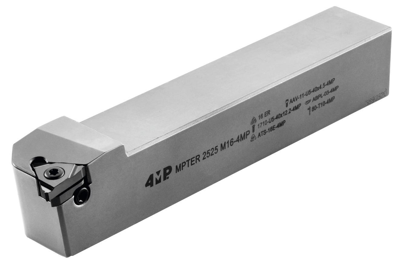
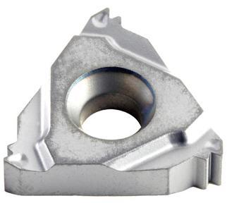
Filettatura / Thearding 02 113 Informazioni tecniche Technical information 117 Codifica Designation system 118 Spessori e accessori specifici Specific shims and accessories 119 Parametri velocità di taglio Cutting parameters 120 Profilo PARZIALE PARTIAL Profile 121 Profilo ISO ISO Profile 122 Profilo UN UN Profile 123 Profilo WHITWORTH WHITWORTH Profile 124 Profilo NPT NPT Profile Inserti di filettatura Threading inserts Filettatura Threading 114 Codifica Designation system 115 Informazioni tecniche Technical information Porta-Inserti di Filettatura Threading toolholders 116 Porta-inserti esterni ed interni External and internal toolholders
112
FILETTATURA
THREADING
Informazioni tecniche
Technical information
I nostr � � nsert � per la f � lettatura offrono una durata utens � le molto lunga e versat � l � tà per tutte le gamme d � mater � al �
Offr � amo un’amp � a selez � one d � � nsert � d � f � lettatura tr � angolar � estern � e � ntern � con un’amp � a var � età d � standard d � f � lettatura.
Our thread � ng � nserts offer super � or tool l � fe and versat � l � ty � n a large range of mater � als. We offer a broad select � on of tr � angular thread turn � ng � nserts for external and � nternal operat � ons and w � de var � ety of thread standards.
APPUNTI / NOTES
1. Raccomandaz � one: scegl � ere la metà del numero d � passate proposte.
Recommendat � on : choose the m � ddle of the proposed passes numbers.
2. P � ù duro è � l mater � ale, magg � ore dovrebbe essere � l numero d � passate. The tougher workp � ece mater � al, the h � gher the number of cutt � ng passes you should select.
3. Regola generale: meno passate sono prefer � b � l � a magg � or veloc � tà. General rule of thumb : fewer passes are better than more speed.
2 P/8 Hh P/4
Screw Nut
1. Nella magg � or parte de � cas � � f � lett � estern � ed � ntern � hanno, a par � tà d � passo, profond � tà e ragg � d � fferent � . Gl � � nsert � ut � l � zzat � non sono qu � nd � � ntercamb � ab � l � In most thread forms, � nternal and external threads have d � fferent depth and rad � us, thus tools are not � nterchangeable. 15° 10°
2. Gl � � nsert � standard 4MP sono stat � progettat � per avere un angolo d � 10° su un portautens � l � esterno e d � 15° su un porta-utens � l � � nterno. Questa d � fferenza d � 5° è necessar � a per avere �� l g � oco rad � ale.
The � nsert rel � ef angle of a standard external toolholder � s 10°; for an � nternal toolholder � t � s 15°. Th � s 5° d � fference � s to prov � de add � t � onal necessary rad � al clearance.
3. Gl � � nsert � d � f � lettatura 4MP devono essere montat � ne � porta-utens � l � corr � spondent � . L’uso d ��� nsert � con supporto esterno causerà d � stors � one angolare e d � stors � one della geometr � a della f � lettatura.
The 4MP thread � ng � nserts must be used � n the � r correspond � ng toolholders. Us � ng � nternal � nserts w � th an external holder w � ll result � n a angle d � stort � on and a d � stors � on of the thread � ng geometry.
4. L’ � nserto e � l portautens � l � devono sempre combac � are. Un � nserto IR deve sempre essere ut � l � zzato con un portautens � l � IR. Non è ammessa alcuna � ncompat � b � l � tà. Insert and toolholder should always match.
An I-R � nsert must be used w � th an IN-RH toolholder. No m � smatch � s allowed.
Scegl� �l numero d� passate �n f�lettatura Number of thread�ng passes select�on 1 Passata Pitch mm TPI 0.5 48 0.8 32 1.0 24 1.25 20 1.5 16 1.75 14 2.0 12 2.5 10 3.0 8 4.0 6 6.0 4 Numero di passate Nb of passes 3-64-74-96-105-119-126-137-158-1710-2011-22 Selezione del numero di passate del filetto per inserti standard Number of thread�ng passes select�on for s�ngle po�nts �nserts
Informaz�on� var� �nsert� d� f�lettatura Thread�ng �nsert �nformat�on
External - 10°
- 15°
Internal
Filettatura / Thearding 113
Gh�era V�te
114 D�rez�one d� tagl�o Cutt�ng d�rect�on 3 R: Destra R : R � ght-Hand L: S � n � stra L : Left-Hand Metodo d� f�ssagg�o dell’�nserto Clamp�ng System 1 S: V � te + Staffa S : Screw Clamp � ng MPT: V � te MPT : Screw Clamp � ng w � th Hel � x Angle T�po d� barra Shank Type 4 A: Barra d’acc � a � o con passagg � o d �� refr � gerante A : Steel shank w � th through coolant E: Barra � n carburo, testa � n acc � a � o con passagg � o d � refr � gerante E: Carb � de shank w � th steel head and w � th trough coolant C: Barra d � carburo C: Carb � de shank S: Barra d’acc � a � o S: Steel shank Appl�caz�one Appl�cat�on 2 E: Esterno E : External I: Interno I : Internal 4 Altezza x Larghezza He � ght x W � dth Porta-�nsert� estern� Shank S�ze 5 D�ametro del corpo Shank D�ameter 5 Lunghezza totale Tool Length 6 A-32 H-100 Q-180 X speciale X-special B-40 J-110 R-200 C-50 K-125 S-250 D-60 L-140 T-300 E-70 M-150 U-350 F-80 N-160 V-400 G-90 P-170 W-450 (mm) L D�mens�on� �nsert� Insert S�ze 7 l (mm) d 06 5/32 08 3/16 11 1/4" 16 3/8" 22 1/2" 27 5/8" Spec�f�c�tà Wedge Clamp 8 4MP Codifica Designation system Esterno / External Interno / Internal
MPT 1 E 2 R 3 M 6 16 7 C 8 25 25 4-5 MPT 1 I 2 R 3 R 6 16 7 C 8 S 4 25 5 Filettatura / Thearding
PORTA-INSERTI DI FILETTATURA THREADING INSERTS
Operaz�on� d� f�lettatura esterna destra
External r�ght hand thread�ng operat�on

ATTENZIONE
Per f � gura B: ut � l � zzare spessore negat � vo
Per f � gure B & D: � mposs � b � le con porta- � nsert � senza spessore
WARNING
For f � gure B : negat � ve sh � m must be used
B and D f � gures can not be appl � ed on tools w � thout sh � m
Operaz�on� d� f�lettatura �nterna destra
Internal r�ght hand thread�ng operat�on
ATTENZIONE
Per f � gura B: ut � l � zzare spessore negat � vo
Per f � gure B & D: � mposs � b � le con porta- � nsert � senza spessore
WARNING :
For f � gure B : negat � ve sh � m must be used
B and D f � gures can not be appl � ed on tools w � thout sh � m
Operaz�on� d� f�lettatura esterna s�n�stra
External left hand thread�ng operat�on
Operaz�on� d� f�lettatura �nterna s�n�stra
Internal left hand thread�ng operat�on
115
A R B L
C L D R
A R B L
C L D R Informazioni tecniche Technical information
Filettatura / Thearding
FILETTATURA
THREADING
Threading, external & internal toolholders
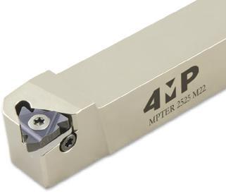
Porta inserto
filettatura esterno
Per inserti per filettare di 16 o 22.
I porta-inserti tipo MPTER/L accettano spessori di angoli diversi permettendo di realizzare tutti i tipi di passi speciali.
External threading toolholder
For threading inserts of 16 or 22. MPTER/L-type insert holders accept shim at di�erent angles allowing all types of special pitchs to be made.
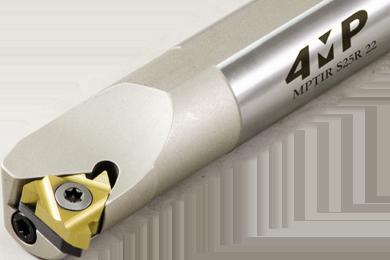
Porta inserto per filettatura interna
Per inserti per filettare di 11, 16 o 22. I porta-inserti tipo MPTER/L accettano spessori di angoli diversi permettendo di realizzare tutti i tipi di passi speciali.
Internal threading toolholder
For threading inserts of 11, 16 or 22. MPT-Type insert holders accept shim at di�erent angles allowing all types of special pitchs to be made.
116 Filettatura / Thearding
Filettatura, porta-inserti esterni e interni
02
Articolo Reference Direzione dell’utensile R/L Hand Larghezza attacco (mm) Shank width (mm) Altezza attacco (mm) Shank height (mm) Passo max. ISO/metrico Max. pitch ISO/Metric Lunghezza totale (mm) Total length (mm) Tipo di inserto Suitable insert Codice Code MPTER 1616 H16-4MP Destra / Right 16 16 3,50 100 16ER 67 430 727 MPTER 2020 K16-4MP Destra / Right 20 20 3,50 125 16ER 67 430 735 MPTER 2525 M16-4MP Destra / Right 25 25 3,50 150 16ER 67 430 743 MPTER 2525 M22-4MP Destra / Right 25 25 5 150 22ER 67 430 751 MPTEL 1616 H16-4MP Sinistra / Left 16 16 3,50 100 16EL 67 430 778 MPTEL 2020 K16-4MP Sinistra / Left 20 20 3,50 125 16EL 67 430 786 MPTEL 2525 M16-4MP Sinistra / Left 25 25 3,50 150 16EL 67 430 794 MPTEL 2525 M22-4MP Sinistra / Left 25 25 5 150 22EL 67 430 808
Articolo Reference Direzione dell’utensile R/L Hand Diametro gambo (mm) Body shank diameter (mm) Diametro minimo foro (mm) Diameter for passage mini (mm) Passo max. ISO/metrico Max. pitch ISO/Metric Lunghezza totale (mm) Total length (mm) Tipo di inserto Suitable insert Codice Code SIRS12K11-4MP Destra / Right 12 16 1,75 125 11IR 65 254 026 SIRS16M11-4MP Destra / Right 16 19 1,75 150 11IR 65 254 034 SIRS16M16-4MP Destra / Right 16 19 3,5 150 16IR 65 254 042 SIRS20P16-4MP Destra / Right 20 24 3,5 170 16IR 65 254 050 MPTIR S25R 16-4MP Destra / Right 25 29 3,5 100 16IR 67 430 816 MPTIR S32S 16-4MP Destra / Right 32 36 3,5 125 16IR 67 430 824 MPTIR S25R 22-4MP Destra / Right 25 29 5 150 22IR 67 430 832 MPTIR S32S 22-4MP Sinistra / Right 32 36 5 150 22IR 67 430 840 SILS12K11-4MP Sinistra / Left 12 16 1,75 125 11IL 65 253 968 SILS16M11-4MP Sinistra / Left 16 19 1,75 150 11IL 65 253 976 SILS16M16-4MP Sinistra / Left 16 19 3,5 150 16IL 65 253 984 SILS20P16-4MP Sinistra / Left 20 24 3,5 170 16IL 65 253 992 MPTIL S25R 16-4MP Sinistra / Left 25 29 3,5 100 16IL 67 430 859 MPTIL S32S 16-4MP Sinistra / Left 32 36 3,5 125 16IL 67 430 867 MPTIL S25R 22-4MP Sinistra / Left 25 29 5 150 22IL 67 430 875 MPTIL S32S 22-4MP Sinistra / Left 32 36 5 150 22IL 67 430 883
117 Codifica Designation system E F � lettatura esterna External thread I F � lettatura � nterna Internal thread F�lettatura Thread 1 R F � lettatura destra R � ght handed L F � lettatura s � n � stra Left handed Senso d� rotaz�one Sense of rotat�on 2 Passo / P � tch (TPI) ISO 0,5 - 5,0 UN 12 - 20 W 11 - 28 NPT 11,5 - 14 Solo se prof�lo completo Only for full prof�le 5 F = F � lettatura / Thread � ng P = R � vest � mento PVD / Coat � ng : PVD 30 = Grado ISO / Grade ISO B = 2º generaz � one / 2 nd Grade generat � on U = Grado un � versale / Un � versal Grade Grado Grade 6 Destra / R � ght D�mens�one dell’�nserto / Insert s � ze L (mm) IC (mm) 11 11 6,3 16 16 9,5 22 22 12,7 Sinistra / Left D�mens�one dell’�nserto / Insert s � ze L IC 11 11 6,3 16 16 9,5 22 22 12,7 D�mens�one dell’�nserto Insert sıze 3 B A I.C. L B A I.C. L 60 grad� / 60 degrees 55 grad� / 55 degrees Codice/ Code Passo / P � tch (mm) Codice/ Code Passo / P � tch (TPI) A 0,5 - 1,5 A 48 - 16 G 1,75 - 3,0 G 14 - 8 AG 0,5 - 3,0 AG 48 - 8 N 3,5 - 5,0 N 7 - 5 Codice/ Code ISO METRIC 60° UN Unified National 60° W Withworth 55° Prof�lo parz�ale / Part�al prof�le 4 Prof�lo completo / Full
INSERT THREAD THREAD INSERT ISO 4 FP30BU 6 1.0 5 R 2 E 1 16 3 INSERTI DI FILETTATURA THREADING INSERTS Filettatura / Thearding
prof�le
I portautens � l � sono costru � t � con un angolo dell’el � ca d � 1,5°. Questo angolo può essere regolato per adattars � megl � o all’angolo dell’el � ca del f � letto sempl � cemente camb � ando lo spessore.
Toolholders are bu�lt w�th 1.5° hel�x angle. Th�s angle may be adjusted to better match the thread hel�x angle by s�mply chang�ng the sh�m.
Hel�x angle depend�ng on d�ameter and p�tch
Sh�ms references depend�ng on hel�x angle
*Attenzione: questo tipo di spessore può essere montato solo su porta-inserti tipo TER/L o TIR/L
* Warn�ng : Th�s type of sh�ms for spec�al steps can only be f�tted on type TER/L or TIR/L �nsert holders
L’el � ca negat � va v � ene t � p � camente ut � l � zzata per la f � lettatura destra con portautens � l � s � n � stro o la f � lettatura s � n � stra con portautens � l � destro
Negat�ve hel�x �s usually used when thread�ng r�ght hand thread w�th left hand holder or left hand thread w�th r�ght hand holder
* Vedere la tabella dell’angolo dell’elica sopra / See helix angle table above
118 1° 10 3/8 5 4 3 5 6 2.5 2 1.5 1 0.5 8 10 12 16 24 48 20 3/4 4° 3° 2° 30 1.25 40 1.5 50 2 60 2.5 75 3 mm inch Diameter TPI D P ћ Utilizzo Use Dimensione dell’inserto Insert Size 4,5° 3,5° 2,5° 1,5° Standard 0,5° -0,5° Rif Spessorea Shim Ref. Codice Code Rif Spessorea Shim Ref. Codice Code Rif Spessore Shim Ref. Codice Code Rif Spessore Shim Ref. Codice Code Rif Spessore Shim Ref. Codice Code Rif Spessore Shim Ref. Codice Code ER o IL 16ATS-16E+4.567 430 956ATS-16E+3.567 430 999ATS-16E+2.567 431 030 ATS-16E67 431 073 ATS-16E+0.567 431 138ATS-16E-0.567 431 170 EL o IR 16 ATS-16I+4.567 430 964ATS-16I+3.567 431 006ATS-16I+2.567 431 049 ATS-16I67 431 081 ATS-16I+0.567 431 146ATS-16I-0.567 431 189 ER o IL 22ATS-22E+4.567 430 972ATS-22E+3.567 431 014ATS-22E+2.567 431 057 ATS-22E67 431 103 ATS-22E+0.567 431 154ATS-22E-0.567 431 197 EL o IR 22ATS-22I+4.567 430 980ATS-22I+3.567 431 022ATS-22I+2.567 431 065 ATS-22I67 431 111 ATS-22I+0.567 431 162ATS-22I-0.567 431 200
Accessori Accessories Vite inserto Insert Screw Spessore Shim Vite dello spessore Shim Screw Chiave di serraggio Wrench Porta-inserto Toolholder Designazione 4MP Designation 4MP Codice Code Designazione 4MP Designation 4MP Codice Code Designazione 4MP Designation 4MP Codice Code SIR/L…..11 4008-M2.5x6 65 252 066 - - - 80-T08 65 252 171 SIR/L D16/D20..16 4015-M3.5x11 65 252 139 - - - 80-T15 65 252 201 MPTER/L…..16 1710-U5-40x12,2 67 430 905 * AAV-11-U5-40x4.5 67 430 921 80-T10 65 252 198 MPTER/L…..22 1720-U8-32x15 67 430 913 * AAV-12-U8-32x5.5 67 430 948 80-T20 67 430 891 MPTIR/L…..16 1710-U5-40x12,2 67 430 905 * AAV-11-U5-40x4.5 67 430 921 80-T10 65 252 198 MPTIR/L…..22 1720-U8-32x15 67 430 913 * AAV-12-U8-32x5.5 67 430 948 80-T20 67 430 891
Angolo dell’el�ca �n funz�one del passo e del d�ametro
Tabella d� r�fer�mento degl� spessor� secondo l’angolo dell’el�ca
Porte-outi / Toolholder ћ Plaquet e / Insert Ass se / Sh m Scelta Choice ß = angolo standard
Filettatura / Thearding
y Plaquette/Insert Assise/Shim ћ Porte-out l / Too holder Negative Helix Hélice négative y
SPESSORI SPECIFICI SPECIFIC SHIMS
FILETTATURA
THREADING
Parametri velocità di taglio
Cutting parameters
*I parametri di taglio e�ettivi devono essere regolati in base a fattori quali la rigidità della macchina, il corpo dell’utensile, le condizioni del pezzo e il refrigerante.
*Above chart for general cutting conditions. The actual selection should be adjusted according to factors such as machine rigidity, tool body, workpiece conditions and coolant.
119
ISO Classificazione dei materiali Material classification AFNOR DIN Durezza Tensile strength (N / mm2) Durezza Hardness (HB) Grado Grade FP30BU min max Velocità di taglio Cutting speed Vc (m/min) P Acciaio non legato Non-alloyed steel / Low Alloyed S300 - 16NC6 9SMn36- 15CrNi6 < 600 < 180 115 190 XC18 - 16NC6 Ck15 - 15NiCr6 < 950 < 280 90 165 Acciaio legato Alloyed steel 42CD4 - XC60 42CrMo4 - Ck60 700 - 950 200 - 280 70 170 Z40CDV4 X40CrMoV5 950 - 1200 280 - 355 70 135 55NCDV7 - Z40C14 55NiCrMoV6 X30Cr13 1200 - 1400 355 - 415 -M Acciaio inossidabile Duplex stainless steel Z2CNDN22.05 X2CrNiMoN22-5 778 230 40 110 Acciaio inossidabile austenitico Austenitic stainless steel 304L - 316L - Z6CN18.09 304, 316, X6CrNi18-10 675 200 90 140 Acciaio inossidabile molto tenace e altamente legato Precipitation hardening stainless steel Z3CNDN25.07Az X2CrNiMoN25 7 4 1013 300 60 110 K Ghisa grigia Grey cast iron FT20D - FT40D GG20, GG40 700 220 70 130 Ghisa lamellare Nodular cast iron FGS400-12 - FGS700-2 GGG40, GGG70 880 260 90 160 Ghisa malleabile Malleable cast iron P540/5 GTS 55 04 800 250 60 145 S Superleghe a base di ferro Fe-based alloy Discalloy 943 280 45 60 Superleghe a base di cobalto Co-based alloy Stellite 21 1076 320 20 40 Superleghe a base di nichel Ni-based alloy Inconel 718 1177 350 20 30 Lega di titanio Ti-alloy TiAl6V4 1262 370 50 70 H Acciaio cementato, per utensili, temprato, al manganese, ecc. Hardened steel 100C6 - Z40CDV5 Z120M12 100Cr6 - X40CrMoV5 1 X120Mn12 - 50-60HRC 40 60 Ghisa bianca Chilled cast iron Grade 2B FB Ni4 Cr2HC - 55HRC 40 50 NF Alluminio < 9% Aluminum < 9% A-U4SG AlCuSiMn 260 75 100 365 Lega di alluminio Aluminum alloy A-S10G G-AlSi10Mg 447 130 200 400
Filettatura / Thearding
Filettatura, inserti Threading inserts 02 120 Filettatura / Thearding Esterno, dritto External Right B A I.C. L Interno, dritto Internal Right B A I.C. L Profilo parziale A.G.AG.N 55 55° NUT 55SCREW 60 SCREW 60 NUT 60°
INSERT THREAD - Soluzione economica Most economical solution - Utilizzare per passi diversi Used for wide range of pitches - Chiamata “parziale” perché il diametro esterno o il diametro interno non sono lavorati Called «partial» because the outside diameter or the inside diameter isn’t machined Profilo/Profile PASSO/Pitch PROFILO PARZIALE/ PROFIL PARTIEL CODE mm TPI 60°, 55° A 0,5 - 1,548 - 16 G 1,75 - 3,014 - 8 AG0,5 - 3,048 - 8 N 3,5 - 5,07 5 Passo Pitch Tipo filettatura Threading type Est/Int Exter/ inter Destra/Sinistra Right / Left Grado Grade Articolo Reference Codice Code L I.C 14 - 8 Profilo parziale 55° Profil partiel 55° E Destra / Right FP30BU ER16 G55 FP30BU-4MP 69 283 19516 9,525 48 - 8 Profilo parziale 55° Profil partiel 55° E Destra / Right FP30BU ER16 AG55 FP30BU-4MP 69 283 20916 9,525 0,5 - 3,0 Profilo parziale 60° Profil partiel 60° E Destra / Right FP30BU ER16 AG60 FP30BU-4MP 69 283 21716 9,525 0,5 - 1,5 Profilo parziale 60° Profil partiel 55° E Destra / Right FP30BU ER16 A60 FP30BU-4MP 69 283 18716 9,525 1,75 - 3,0 Profilo parziale 60° Profil partiel 55° E Destra / Right FP30BU ER16 G60 FP30BU-4MP 69 283 22516 9,525 3,5 - 5,0 Profilo parziale 60° Profil partiel 55° E Destra / Right FP30BU ER22 N60 FP30BU-4MP 69 283 40322 12,7
PROFILO PARZIALE
Esterno / External
Passo Pitch Tipo filettatura Threading type Est/Int Exter/ inter Destra/ Sinistra Right / Left Grado Grade Articolo Reference Codice Code L I.C 14 - 8 Profilo parziale 55° Profil partiel 55° I Destra / Right FP30BU IR16 G55 FP30BU-4MP 69 283 44616 9,525 48 - 8 Profilo parziale 55° Profil partiel 55° I Destra / Right FP30BU IR16 AG55 FP30BU-4MP 69 283 45416 9,525 0,5 - 1,5 Profilo parziale 60° Profil partiel 60° I Destra / Right FP30BU IR11 A60 FP30BU-4MP 69 283 411 11 6,35 0,5 - 3,0 Profilo parziale 60° Profil partiel 60° I Destra / Right FP30BU IR16 AG60 FP30BU-4MP 69 283 46216 9,525 0,5 - 1,5 Profilo parziale 60° Profil partiel 60° I Destra / Right FP30BU IR16 A60 FP30BU-4MP 69 283 43816 9,525 1,75 - 3,0 Profilo parziale 60° Profil partiel 60° I Destra / Right FP30BU IR16 G60 FP30BU-4MP 69 283 47016 9,525 3,5 - 5,0 Profilo parziale 60° Profil partiel 60° I Destra / Right FP30BU IR22 N60 FP30BU-4MP 69 283 61622 12,7 Dimensioni (mm ) / Dimensions (mm) Dimensioni (mm ) / Dimensions (mm)
Interno / Internal
ISO NUT 60° 1/4P 1/8P
ISO SCREW
ISO 965-1: 1999-11 DIN13: 2005-08
Esterno / External
Profilo completo / Entire profile
THREAD
Interno / Internal
ISO metrico esterno: numero consigliato di passate
External metric ISO : recommended nb of passes
INSERT
L’intera filettatura viene eseguita in modo da soddisfare lo standard richiesto
The entire shape is done to meet the required standard
Ampia gamma di inserti per adattarsi ad ogni standard e tipo di passo applicabile
Wide range of inserts in order to fit each standard and range of pitches
Internal metric ISO : recommended nb of passes ISO
ISO metrico interno: numero consigliato di passate
Filettatura, inserti Threading inserts 02 121 Filettatura / Thearding Dimensioni (mm) / Dimensions (mm) Dimensioni (mm) / Dimensions (mm) Passo Pitch Tipo filettatura Threading type Est/ Int Exter/ inter Destra/ Sinistra Right / Left Grado Grade Articolo Reference Codice Code L I.C A B 1,0 ISO I Destra / Right FP30BUIR16 ISO 1.0 FP30BU-4MP 69 283 489 16 9,5251,4 0,7 1,25 ISO I Destra / Right FP30BUIR16 ISO 1.25 FP30BU-4MP 69 283 497 16 9,5251,3 0,8 1,5 ISO I Destra / Right FP30BUIR16 ISO 1.5 FP30BU-4MP 69 283 500 16 9,5251,2 0,9 1,75 ISO I Destra / Right FP30BUIR16 ISO 1.75 FP30BU-4MP 69 283 519 16 9,5251,3 1,1 2,0 ISO I Destra / Right FP30BUIR16 ISO 2.0 FP30BU-4MP 69 283 527 16 9,5251,3 1,3 2,5 ISO I Destra / Right FP30BUIR16 ISO 2.5 FP30BU-4MP 69 283 535 16 9,5251,2 1,4 3,0 ISO I Destra / Right FP30BUIR16 ISO 3.0 FP30BU-4MP 69 283 543 16 9,5251,1 1,5 Passo Pitch Tipo filettatura Threading type Est/ Int Exter/ inter Destra/ Sinistra Right / Left Grado Grade Articolo Reference Codice Code L I.C A B 1,0 ISO E Destra / Right FP30BUER16 ISO 1.0 FP30BU-4MP 69 283 233 16 9,5251,5 0,7 1,25 ISO E Destra / Right FP30BUER16 ISO 1.25 FP30BU-4MP69 283 241 16 9,5251,4 0,8 1,5 ISO E Destra / Right FP30BUER16 ISO 1.5 FP30BU-4MP 69 283 268 16 9,5251,3 0,9 1,75 ISO E Destra / Right FP30BUER16 ISO 1.75 FP30BU-4MP69 283 276 16 9,5251 1,1 2,0 ISO E Destra / Right FP30BUER16 ISO 2.0 FP30BU-4MP 69 283 284 16 9,5251,4 1,3 2,5 ISO E Destra / Right FP30BUER16 ISO 2.5 FP30BU-4MP 69 283 292 16 9,5251,6 1,5 3,0 ISO E Destra / Right FP30BUER16 ISO 3.0 FP30BU-4MP 69 283 306 16 9,5251,6 1,6 Numero di passate Nb of passes Passo e profondità delle passate Pitch and depth of each pass 3 2,5 2 1,75 1.5 1,25 1 0,75 1 0,27 0,26 0,24 0,23 0,20 0,20 0,19 0,17 2 0,23 0,22 0,23 0,21 0,23 0,18 0,16 0,15 3 0,20 0,20 0,19 0,16 0,23 0,14 0,13 0,11 4 0,18 0,17 0,17 0,14 0,23 0,12 0,10 0,06 5 0,17 0,16 0,15 0,12 0,23 0,10 0,06 6 0,16 0,14 0,14 0,10 0,23 0,06 7 0,15 0,13 0,11 0,08 0,23 8 0,13 0,12 0,09 0,06 0,23 9 0,12 0,10 0,06 10 0,11 0,06 11 0,09 12 0,06 13 14 Totale / Total 1,87 1,56 1,26 1,10 0,950,800,640,49 Numero di passate Nb of passes Passo e profondità delle passate Pitch and depth of each pass 3 2,5 2 1,75 1,5 1,25 1 0,75 1 0,25 0,26 0,24 0,23 0,20 0,20 0,19 0,17 2 0,22 0,22 0,23 0,21 0,23 0,18 0,16 0,15 3 0,19 0,20 0,19 0,16 0,23 0,14 0,13 0,11 4 0,17 0,17 0,17 0,14 0,23 0,12 0,10 0,06 5 0,17 0,16 0,15 0,12 0,23 0,10 0,06 6 0,16 0,14 0,14 0,10 0,23 0,06 7 0,15 0,13 0,11 0,08 0,23 8 0,13 0,12 0,09 0,06 0,23 9 0,12 0,10 0,06 10 0,11 0,06 11 0,09 12 0,06 13 14 Totale / Total 1,87 1,56 1,26 1,10 0,950,800,640,49
B A I.C. L B A I.C. L Esterno, dritto External Right Interno, dritto Internal Right
Filettatura, inserti Threading inserts 02 122 Filettatura / Thearding Dimensioni (mm) / Dimensions (mm) Dimensioni (mm) / Dimensions (mm) Esterno, dritto External Right B A I.C. L Interno, dritto Internal Right B A I.C. L NUT UN SCREW 60° 1/4P 1/8P UN ANSI B1.1-1982 THREAD INSERT Profilo completo / Entire profile - L’intera filettatura viene eseguita in modo da soddisfare lo standard richiesto The entire thread is done to meet the required standard - Ampia gamma di inserti per adattarsi ad ogni standard e tipo di passo applicabile Wide range of inserts in order to fit each standard and range of pitches
Passo Pitch Tipo filettatura Threading type Est/Int Exter/ inter Destra/ Sinistra Right / Left Grado Grade Articolo Reference Codice Code L I.C A B 12 UN E Destra / Right FP30BUER16 UN 12 FP30BU-4MP 69 283 314 16 9,5251,3 1,4 16 UN E Destra / Right FP30BUER16 UN 16 FP30BU-4MP 69 283 322 16 9,5251,2 1,1 20 UN E Destra / Right FP30BUER16 UN 20 FP30BU-4MP 69 283 330 16 9,5251,4 0,8 Passo Pitch Tipo filettatura Threading type Est/Int Exter/ inter Destra/ Sinistra Right / Left Grado Grade Articolo Reference Codice Code L I.C A B 12 UN I Destra / Right FP30BUIR16 UN 12 FP30BU-4MP 69 283 551 16 9,5251,4 1,4 16 UN I Destra / Right FP30BUIR16 UN 16 FP30BU-4MP 69 283 578 16 9,5251,1 0,9 Numero di passate Nb of passes Passo e profondità delle passate Pitch and depth of each pass 20 16 12 1 0,20 0,22 0,25 2 0,16 0,20 0,23 3 0,15 0,18 0,20 4 0,13 0,14 0,18 5 0,11 0,11 0,16 6 0,06 0,09 0,14 7 0,06 0,11 8 0,06 9 Totale / Total 1,33 1,00 1,33
di passate Nb of passes Passo e profondità delle passate Pitch and depth of each pass 16 12 1 0,21 0,24 2 0,19 0,21 3 0,17 0,19 4 0,13 0,17 5 0,10 0,15 6 0,09 0,13 7 0,06 0,10 8 0,06 9 Totale / Total 0,95 1,25 UNO esterno: numero consigliato di passate External UN : recommended nb of passes UN interno: numero consigliato di passate di filiettatura Internal metric UN : recommended nb of passes
UN
Numero
Interno / Internal
Esterno / External
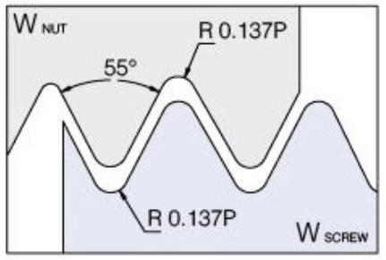
Filettatura, inserti Threading inserts 02 123 Filettatura / Thearding Dimensioni (mm) / Dimensions (mm) Dimensioni (mm) / Dimensions (mm) Esterno, dritto External Right B A I.C. L Interno, dritto Internal Right B A I.C. L B.S.84 : 1956 IISO228-1 : 1994 THREAD INSERT Profilo completo / Entire profile
eseguita
da soddisfare lo standard richiesto The entire thread is
to meet the required standard
Ampia
di inserti
adattarsi
tipo di passo applicabile Wide range of inserts in order to fit each standard and range of pitches
Passo Pitch Tipo filettatura Threading type Est/Int Exter/ inter Destra/ Sinistra Right / Left Grado Grade Articolo Reference Codice Code L I.C A B 11 W E Destra / Right FP30BUER16 W 11 FP30BU-4MP 69 283 349 16 9,5251,4 1,5 14 W E Destra / Right FP30BUER16 W 14 FP30BU-4MP 69 283 357 16 9,5251,1 1,2 19 W E Destra / Right FP30BUER16 W 19 FP30BU-4MP 69 283 365 16 9,5250,8 1 Passo Pitch Tipo filettatura Threading type Est/Int Exter/ inter Destra/ Sinistra Right / Left Grado Grade Articolo Reference Codice Code L I.C A B 11 W I Destra / Right FP30BUIR16 W 11 FP30BU-4MP 69 283 586 16 9,5251,3 1,4 14 W I Destra / Right FP30BUIR16 W 14 FP30BU-4MP 69 283 594 16 9,5251,2 1,2 Numero di passate Nb of passes Passo e profondità delle passate Pitch and depth of each pass 28 19 14 11 1 0,006 0,22 0,24 0,26 2 0,006 0,19 0,21 0,23 3 0,005 0,17 0,17 0,20 4 0,005 0,14 0,15 0,18 5 0,003 0,11 0,14 0,17 6 0,12 0,16 7 0,10 0,13 8 0,06 0,12 9 0,06 Totale / Total 0,25 0,89 1,19 1,51 Whitworth esterno e interno: numero consigliato delle passate External and internal withworth : recommended number of passes Interno / Internal Esterno / External
- L’intera filettatura viene
in modo
done
-
gamma
per
ad ogni standard e
WHITWORTH
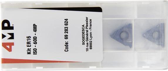
Filettatura, inserti Threading inserts 124 Filettatura / Thearding Dimensioni (mm) / Dimensions (mm) Dimensioni (mm) / Dimensions (mm) Dimensioni (mm) / Dimensions (mm)
Esterno, dritto External Right B A I.C. L Interno, dritto Internal Right B A I.C. L ANSI/ASME B 1.20.1-1983 NPT NUT 30° 30° 90° 1”47 NPT SCREW Profilo completo Entire profile Esterno / External Passo Pitch Tipo filettatura Threading type Est/Int Exter/ inter Destra/ Sinistra Right / Left Grado Grade Articolo Reference Codice Code L I.C A B 11,5 NPT E Destra / Right FP30BUER16 NPT 11.5 FP30BU-4MP69 283 373 16 9,5251,1 1,5 14 NPT E Destra / Right FP30BUER16 NPT 14 FP30BU-4MP 69 283 381 16 9,5250,9 1,2 Passo Pitch Tipo filettatura Threading type Est/Int Exter/ inter Destra/ Sinistra Right / Left Grado Grade Articolo Reference Codice Code L I.C A B 11,5 NPT I Destra / Right FP30BUIR16 NPT 11.5 FP30BU-4MP 69 283 608 16 9,5251,2 1,4 Interno / Internal Kit di filettatura Kit da 5 inserti Threading sets 5 inserts sets Passo Pitch Tipo filettatura Threading type Est/ Int Exter/ inter Destra/ Sinistra Right / Left Grado Grade Articolo Reference Codice Code L ERA60 / ERG60 / ERAG60 / IRA60 / IRAG60 ISO E/I Droite / Right FP30BUKIT ER16/IR16 ISO-60D-4MP69 283 64016 ER1,0 / ER1,5 / ER2,0 / ER2,5 / ER3,0 ISO E Droite / Right FP30BUKIT ER16 ISO-60D-4MP 69 283 62416 IR1,0 / IR1,5 / IR2,0 / IR2,5 / IR3,0 ISO I Droite / Right FP30BUKIT IR16 ISO-60D-4MP 69 283 63216 ER11W/ ER14W / ER19W / ERG55 / ERAG55 W E Droite / Right FP30BUKIT ER16 W-55D-4MP 69 283 65916 IR11W / IR14W / IRG55 / IRAG55 (x2) W I Droite / Right FP30BUKIT IR16 W-55D-4MP 69 283 66716 02
NPT
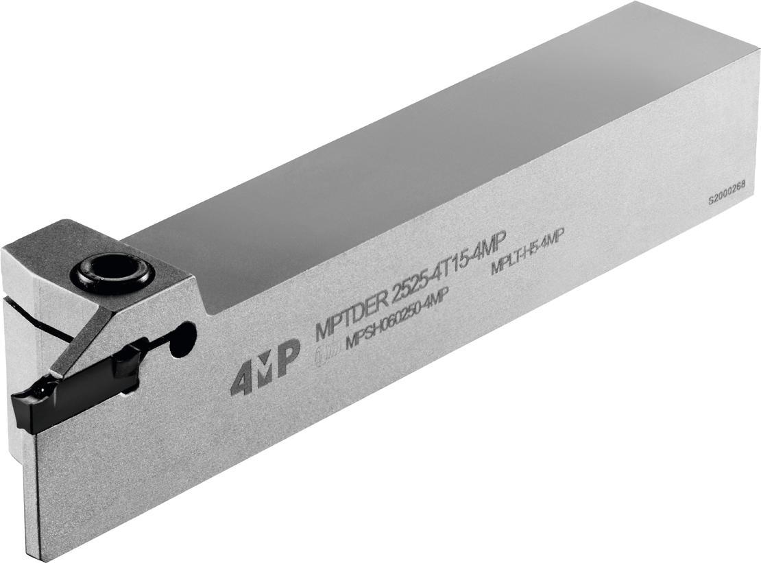

02
Scanalatura / Grooving
Porta-inserti per scanalatura Grooving toolholders Codifica Designation system 126 Gamma dei porta-inserti Grooving toolholders overview 127 Inserti per scanalatuta Grooving inserts 134 Geometria degli inserti Inserts geometry 133 Codifica Designation system Scelta degli inserti per applicazione Machining inserts selector 135 136 Gradi ISO ISO grades Scelta dei gradi 137 Grades selector Parametri velocità di taglio Cutting parameters 138 Inserti per scanalatura Grooving inserts 139 132 Lame e porta-lama Blades for parting and blade holder 131 Porta-inserti per scanalature interne Internal grooving toolholders 128 Porta-inserti per scanalature esterne External grooving toolholders 125
SCANALATURA GROOVING
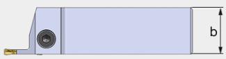
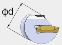
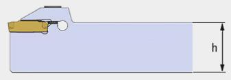
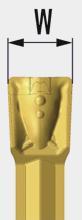
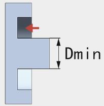
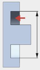

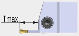
126 Codifica Designation system Marca Brand 1 MP = 4MP Appl�caz�one Appl�cat�on 2 G = Inserto / Grooving T = Multidirezionale / Turning E : Esterno / External I : Interno / Internal F : Frontale / Facing T�po d� lavoraz�one Mach�n�ng type 4 E 4 R 5 32 6 25 7 25 8 D 3 T 2 4 9 MP 1 80 12 A 13 T25 10 40 11 D : Dritto -180° / Straight-180° A : Angolo -45° / Under cut-45° P : Perpendicolare -90° / Perpendicular-90° Or�entamento dell’�nserto Inserts pos�t�onn�ng 3 L : Sinistra / Left hand R : Destra / Right hand D�rez�one dell’utens�le Hand of tool 5 20 = 20,0 mm 25 = 25,0 mm 32 = 32,0 mm D�ametro f�ssagg�o Holder d�ameter 6 20 = 20,0 mm 25 = 25,0 mm 32 = 32,0 mm Larghezza utens�le Holder w�dth 8 40 = 40,0 mm D�ametro m�n�mo della scanalatura anter�ore M�n�. cutt�ng d�am. 11 2 = 2,0 mm 3 = 3,0 mm 4 = 4,0 mm Larghezza �nserto Insert w�dth 9 80 = 80,0 mm D�ametro mass�mo della scanalatura anter�ore Max.cutt�ng d�am. 12 T25 = Tmax. 25 mm Profond�tà mass�ma Max�mum depth 10 A : Con passaggio di refrigerante With internal coolant D : Rinforzato Reinforced holders Cod�ce spec�ale Spec�al code 13 20 = 20,0 mm 25 = 25,0 mm 32 = 32,0 mm Altezza utens�le Holder he�ght 7 OU / OR
SCANALATURA
Scanalatura / Grooving
PORTA-INSERTI PER
GROOVING TOOLHOLDERS
PORTA-INSERTI PER SCANALATURA GROOVING TOOLHOLDERS
Gamma degli inserti per scanalatura Grooving toolholders overview
Scanalature esterne External groovings Scanalature anteriori Face groovings Scanalature interne Internal groovings Troncatura Parting
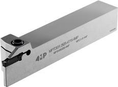

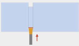
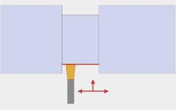
Scanalature interne Internal groovings Scanalatura Grooving
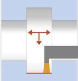
• Scelta di base / Best choice
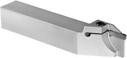
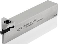

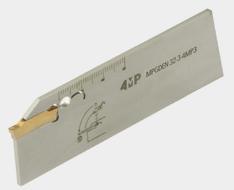
127
• • •
• • •
• •
• •
•
•
•
•
Applicazione
Page 129
MPTDER/L MPTDER/L-D MPGDFR/L MPTPIR/L MPGDEN Scanalature esterne External groovings Troncatura Parting o�
Scanalatura Grooving
Tornitura Turning
Profilatura Profiling
Scanalature frontali Face groovings Scanalatura Grooving
Tornitura Turning
Tornitura Turning
Porta-inserti Toolholders
Application
Page 131 Page 128 Page 130 Page 132 Scanalatura / Grooving
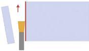
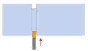
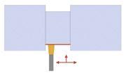
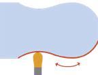
128 Scanalatura / Grooving
si
un porta-inserti per scanalatura, controllare il diametro di taglio (Dmin-Dmax) degli utensili / When you select a grooving toolholder, please check the cutting diameter (Dmin-Dmax)
Quando
seleziona
Articolo Reference Dimensioni (mm) / Dimensions (mm) Inserti Inserts Codice Code h b H1 H2 A L1 L2 F Tmax MPTDER 1616-4T10-4MP 16 16 16 4 3 110 32 14,5 10GTD/GGD…4 67 064 275 MPTDER 1616-4T25-4MP 16 16 16 4 3 110 45 14,5 25GTD/GGD…4 67 064 283 MPTDER 2020-4T10-4MP 20 20 20 0 3 125 32 18,5 10GTD/GGD…4 67 064 291 MPTDER 2020-4T25-4MP 20 20 20 0 3 125 45 18,5 25GTD/GGD…4 67 064 305 MPTDER 2525-4T15-4MP 25 25 25 0 3 150 32 23,515GTD/GGD…4 67 064 313 MPTDER 2525-4T25-4MP 25 25 25 0 3 150 45 23,525GTD/GGD…4 67 064 321
Porta-inserto destro Right toolholder
Articolo Reference Dimensioni (mm) / Dimensions (mm) Inserti Inserts Codice Code h b H1 H2 A L1 L2 F Tmax MPTDEL 1616-4T10-4MP 16 16 16 4 3 110 32 14,5 10GTD/GGD…4 67 064 348 MPTDEL 1616-4T25-4MP 16 16 16 4 3 110 45 14,5 25GTD/GGD…4 67 064 356 MPTDEL 2020-4T10-4MP 20 20 20 0 3 125 32 18,5 10GTD/GGD…4 67 064 364 MPTDEL 2020-4T25-4MP 20 20 20 0 3 125 45 18,5 25GTD/GGD…4 67 064 372 MPTDEL 2525-4T15-4MP 25 25 25 0 3 150 32 23,515GTD/GGD…4 67 064 380 MPTDEL 2525-4T25-4MP 25 25 25 0 3 150 45 23,525GTD/GGD…4 67 064 399
Porta-inserto
sinistro Left toolholder
02 Accessori Accessories Vite Screw Chiave di serraggio Wrench Designazione porta-inserti Toolholder designation Articolo Reference Codice Code Articolo Reference Codice Code MPTDER/L 1616-4 MPSH060160-4MP 67 065 123 MPLT-H5-4MP 67 065 174 MPTDER/L 2020-4 MPSH060200-4MP 67 065 131 MPLT-H5-4MP 67 065 174 MPTDER/L 2525-4 MPSH060250-4MP 67 065 158 MPLT-H5-4MP 67 065 174 L1 L2 Tmax H2 H1 F A b h
Scanalatura, porta-inserti per scanalature esterne Grooving, external toolholders
Scanalatura, porta-inserti per scanalature esterne Grooving, external toolholders

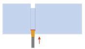
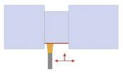
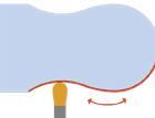
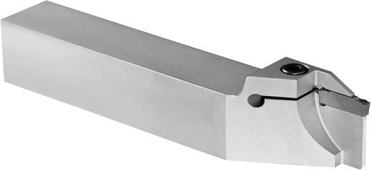
Quando si seleziona un porta-inserti per scanalatura, controllare il diametro di taglio (Dmin-Dmax) degli utensili / When you select a grooving toolholder, please check the cutting diameter (Dmin-Dmax)
129 Scanalatura / Grooving
Vite Screw Chiave di serraggio Wrench Designazione porta-inserti Toolholder designation Articolo Reference Codice Code Articolo Reference Codice Code MPTDER/L-D 1212-2/3 MPSH050160-4MP 67 065 093 MPLT-H4-4MP 67 065 166 MPTDER/L-D 1616-2/3 MPSH050160-4MP 67 065 093 MPLT-H4-4MP 67 065 166 MPTDER/L-D 2020-2/3 MPSH050200-4MP 67 065 107 MPLT-H4-4MP 67 065 166 MPTDER/L-D 2525-2/3 MPSH050250-4MP 67 065 115 MPLT-H4-4MP 67 065 166
sinistro Left toolholder Articolo Reference Dimensioni / Dimensions Inserti Inserts Codice Code h b H1 H2 A L1 L2 FTmaxDmax MPTDEL 1212-2T15-D40-4MP 12 12 12 4 1,8 12532 11,1 15 40GTD/GGD…267 064 518 MPTDEL 1616-2T20-D45-4MP 16 16 16 4 1,8 12538 15,1 20 45GTD/GGD…267 064 526 MPTDEL 2020-2T20-D45-4MP 20 20 20 0 1,8 12538 19,120 45GTD/GGD…267 064 534 MPTDEL 2525-2T20-D45-4MP 25 25 25 0 1,8 15038 24,120 45GTD/GGD…267 064 542 MPTDEL 1212-3T15-D40-4MP 12 12 12 4 2,412532 10,815 40GTD/GGD…367 064 550 MPTDEL 1616-3T20-D45-4MP 16 16 16 4 2,412532 14,820 45GTD/GGD…367 064 569 MPTDEL 2020-3T20-D45-4MP 20 20 20 0 2,412532 18,820 45GTD/GGD…367 064 577 MPTDEL 2525-3T20-D45-4MP 25 25 25 0 2,415032 23,820 45GTD/GGD…367 064 585 Porta-inserto destro Right toolholder Articolo Reference Dimensioni / Dimensions Inserti Inserts Codice Code h b H1 H2A L1 L2 FTmaxDmax MPTDER 1212-2T15-D40-4MP 12 12 12 4 1,81253211,1 15 40GTD/GGD…267 064 402 MPTDER 1616-2T20-D45-4MP 16 16 16 4 1,81253815,1 2045GTD/GGD…267 064 410 MPTDER 2020-2T20-D45-4MP 2020200 1,81253819,12045GTD/GGD…267 064 429 MPTDER 2525-2T20-D45-4MP 2525250 1,81503824,12045GTD/GGD…267 064 437 MPTDER 1212-3T15-D40-4MP 12 12 12 4 2,41253210,815 40GTD/GGD…367 064 445 MPTDER 1616-3T20-D45-4MP 16 16 16 4 2,41253214,82045GTD/GGD…367 064 453 MPTDER 2020-3T20-D45-4MP 2020200 2,41253218,82045GTD/GGD…367 064 461 MPTDER 2525-3T20-D45-4MP 2525250 2,41503223,82045GTD/GGD…367 064 488 MPTDER 2525-3T25-D60-4MP 2525257 2,41504523,82560GTD/GGD…367 064 496 L2 H2 H1 F A h b Tmax ØDmax L1
Accessori Accessories
Porta-inserto
02
Scanalatura, porta-inserti per scanalature esterne Grooving, external toolholders
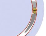
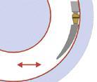
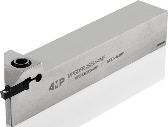
130 Scanalatura / Grooving Porta-inserto destro Right toolholder Porta-inserto sinistro Left toolholder Dimensioni (mm) Dimensions (mm) Dmin scanalatura frontale funzione del rompitruciolo (mm) Dmin face grooving depending chip breaker (mm) Articolo Reference h b H1L1L2 FTmax Dmin inserti GH Dmin inserts GH Dmin inserti TS Dmin inserts TS Dmin inserti TM Dmin inserts TM Inserti Inserts Codice Code MPGDFR 1616-4-4MP 1616161103214,54,6 42 22 22 GTD/GGD…4 67 064 860 MPGDFR 2020-4-4MP 2020201253218,54,6 42 22 22 GTD/GGD…4 67 064 879 MPGDFR 2525-4-4MP 2525251503223,54,6 42 22 22 GTD/GGD…4 67 064 887 Dimensioni (mm) Dimensions (mm) Dmin scanalatura frontale funzione del rompitruciolo (mm) Dmin face grooving depending chip breaker (mm) Articolo Reference h b H1L1L2 FTmax Dmin Inserti GH Dmin inserts GH Dmin Inserti TS Dmin inserts TS Dmin Inserti TM Dmin inserts TM Inserti Inserts Codice Code MPGDFL 1616-4-4MP 1616161103214,54,6 42 22 22 GTD/GGD…4 67 064 895 MPGDFL 2020-4-4MP 2020201253218,54,6 42 22 22 GTD/GGD…4 67 064 909 MPGDFL 2525-4-4MP 2525251503223,54,6 42 22 22 GTD/GGD…4 67 064 917 L1 h b L2 Tmax H1 F Dmin Quando si seleziona un porta-inserti per scanalatura, controllare il diametro di taglio (Dmin-Dmax) degli utensili / When you select a grooving toolholder, please check the cutting diameter (Dmin-Dmax).
Vite Screw Chiave di serraggio Wrench Designazione porta-inserti Toolholder designation Articolo Reference Codice Code Articolo Reference Codice Code MPGDFR/L 1616-4 MPSH060200-4MP 67 065 131 MPLT-H5-4MP 67 065 174 MPGDFR/L 2020-4 MPSH060200-4MP 67 065 131 MPLT-H5-4MP 67 065 174 MPGDFR/L 2525-4 MPSH060250-4MP 67 065 158 MPLT-H5-4MP 67 065 174
Accessori Accessories
02
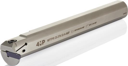
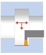
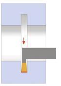
131 Scanalatura / Grooving
destro Right toolholder Dimensioni (mm) Dimensions (mm) Articolo Reference d A L1 L2 F TmaxDmin Inserti Inserts Codice Code MPTPIR 20-2T6-25-A-4MP 20 1,6 160 40 15,8 6 25 GTD/GGD…267 064 593 MPTPIR 25-2T5-25-A-4MP 25 1,6 200 40 17,5 5 25 GTD/GGD…267 064 607 MPTPIR 20-3T6-25-A-4MP 20 2,1 160 40 15,8 6 25 GTD/GGD…367 064 615 MPTPIR 25-3T5-25-A-4MP 25 2,1 200 40 17,5 5 25 GTD/GGD…367 064 623 MPTPIR 25-3T8-32-A-4MP 25 2,4 200 40 21,5 8 32 GTD/GGD…367 064 631 MPTPIR 32-3T5-30-A-4MP 32 2,1 250 60 19,8 5 30 GTD/GGD…367 064 658 MPTPIR 32-3T10-40-A-4MP 32 2,4 200 60 27 10 40 GTD/GGD…367 064 666 MPTPIR 20-4T6-25-A-4MP 20 3 160 40 15,8 6 25 GTD/GGD…467 064 674 MPTPIR 25-4T5-25-A-4MP 25 2,9 200 40 17,5 5 25 GTD/GGD…467 064 682 MPTPIR 25-4T8-32-A-4MP 25 3 200 40 21,5 8 32 GTD/GGD…467 064 690 MPTPIR 32-4T5-30-A-4MP 32 2,9 250 60 20,8 5 30 GTD/GGD…467 064 704 MPTPIR 32-4T10-40-A-4MP 32 3 250 60 27 10 40 GTD/GGD…467 064 712 A L1 d L2 F Tmax Scanalatura, porta-inserti per scanalature interne Grooving, internal toolholders 02 Dmin Porta-inserto sinistro Left toolholder Dimensioni (mm) Dimensions (mm) Articolo Reference d A L1 L2 F TmaxDmin Inserti Inserts Codice Code MPTPIL 20-2T6-25-A-4MP 20 1,6 160 40 15,8 6 25 GTD/GGD…267 064 720 MPTPIL 25-2T5-25-A-4MP 25 1,6 200 40 17,5 5 25 GTD/GGD…267 064 739 MPTPIL 20-3T6-25-A-4MP 20 2,1 160 40 15,8 6 25 GTD/GGD…367 064 747 MPTPIL 25-3T5-25-A-4MP 25 2,1 200 40 17,5 5 25 GTD/GGD…367 064 755 MPTPIL 25-3T8-32-A-4MP 25 2,4 200 40 21,5 8 32 GTD/GGD…367 064 763 MPTPIL 32-3T5-30-A-4MP 32 2,1 250 60 19,8 5 30 GTD/GGD…367 064 771 MPTPIL 32-3T10-40-A-4MP 32 2,4 200 60 27 10 40 GTD/GGD…367 064 798 MPTPIL 20-4T6-25-A-4MP 20 3 160 40 15,8 6 25 GTD/GGD…467 064 801 MPTPIL 25-4T5-25-A-4MP 25 2,9 200 40 17,5 5 25 GTD/GGD…467 064 828 MPTPIL 25-4T8-32-A-4MP 25 3 200 40 21,5 8 32 GTD/GGD…467 064 836 MPTPIL 32-4T5-30-A-4MP 32 2,9 250 60 20,8 5 30 GTD/GGD…467 064 844 MPTPIL 32-4T10-40-A-4MP 32 3 250 60 27 10 40 GTD/GGD…467 064 852
Porta-inserto
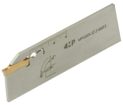
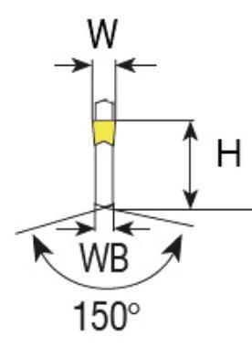
Porta-inserti per scanalature e troncatura
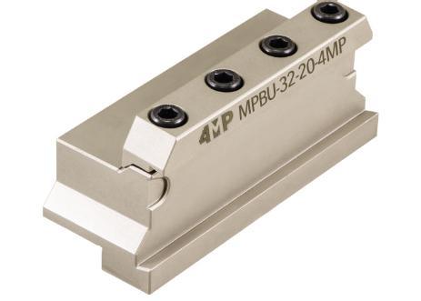
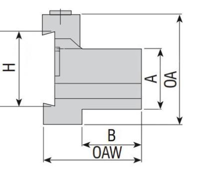
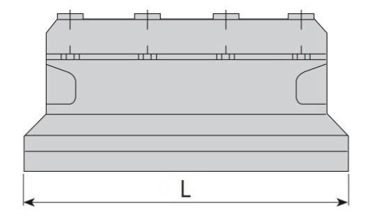
132 Scanalatura / Grooving Accessori Accessories Vite Screw Chiave di serraggio Wrench Designazione porta-inserti Toolholder designation Articolo Reference Codice Code Articolo Reference Codice Code MPTPIR/L 20-2/3/4 MPSH050120-4MP 67 065 085 MPLT-H4-4MP 67 065 166 MPTPIR/L 25-2/3/4 MPSH050160-4MP 67 065 093 MPLT-H4-4MP 67 065 166 MPTPIR/L 32-3/4 MPSH050160-4MP 67 065 093 MPLT-H4-4MP 67 065 166 Chiave di serraggio per lama – Riferimento / Wrench for blade - Reference : MPLT-H6-4MP, Codice 71 013 421 Lama per troncatura e scanalature Blade for parting and grooving Articolo Reference H W WB Lunghezza totale Total length Inserti Inserts Codice Code MPGDEN 32-3-4MP 32 3 2,40 150 GGD/GGM…3 71 013 405 MPGDEN 32-4-4MP 32 4 3,20 150 GGD/GGM…4 71 013 413 Blocco porta-lama Block for parting and grooving blade Articolo Reference H A B OAW L Codice Code MPBU-32-20-4MP 32 20 19 50 100 71 013 383 MPBU-32-25-4MP 32 25 23 50 110 71 013 391 Ricambi per porta-lama Block for parting and grooving blade accessories Vite Screw Chiave di serraggio Wrench Sta�a Clamp Designazione porta-lama Blade toolholder designation Articolo Reference Codice Code Articolo Reference Codice Code Articolo Reference Codice Code MPBU-32-20-4MP 2506-M6x30-4MP 71 171 124 AAL-07-5-4MP 71 171 132 ABK-03-4MP 71 171 140 MPBU-32-25-4MP ABK-04-4MP 71 171 159
Parting and grooving toolholders 02
INSERTI PER SCANALATURA GROOVING INSERTS
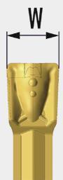
7
T�po d� romp�truc�olo Ch�p breaker type
(G) M =
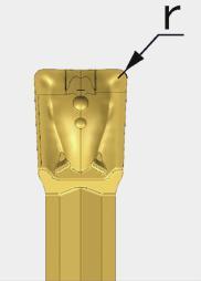
1. Troncatura e scanalature di acciai a basso tenore di carbonio e acciai inossidabili
2. Materiali duttili, raccordi per tubi e parti a parete sottile, bassa forza di taglio
3. Avanzamento da basso a medio. Utilizzo scanalatura e troncatura in acciaio e acciaio inossidabile
1. Applied for parting o� & grooving on low carbon steels and stainless steels
2. For sticky material, pipe fittings, thin-walled parts, parting o�, low cutting force
3. For low to medium feed rate. Applied for parting o� & grooving on low carbon steels and stainless steels
(T) S =
1. Inserto multifunzione: tornitura esterna e interna, troncatura, scanalatura e scanalatura frontale
2. Eccellente controllo del truciolo
3. Avanzamento basso e medio
1. Multifunctional insert for external,internal turning and grooving, parting o� and face grooving and face turning
2. Excellent chip control
3. For low and medium feed rate
(P) M =
1. Tornitura esterna, scanalatura e profilatura
2. Avanzamento medio
1. External, grooving, turning, profiling
2. Medium feed rate
6
Operaz�one completata
Mach�n�ng operat�on

8
G = Inserto / Grooving
T = Tornitura / Turning
P = Profilatura / Profiling
Angolo d� �ncl�naz�one
Cutt�ng edge angle
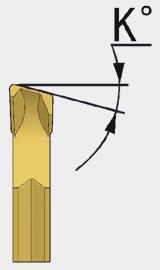
Senso �nserto Hand of �nsert 9
6°
15°
L : Sinistra / Left
R : Destra / Right
133
1 G =
Grooving
3
:
D :
Codifica Designation system Gamma �nsert� Range of �nserts
Inserto /
T�po d� �nserto Insert shape
M
Monolaterale / Mono-ended
Bilaterale / Double-ended
2
= Scanalatura
Grooving T = Tornitura-Scanalatura
Turning-Grooving G 6 M 7 6 8 R 9 3 4 02 5 D 3 G 2 G 1 2 = 2,0 mm 3 = 3,0 mm 4 = 4,0 mm Larghezza
w�dth 4 02 = 0,2 mm 03 = 0,3 mm 04 = 0,4 mm
5
Appl�caz�one Appl�cat�on
G
/
/
�nserto Insert
Ragg�o �nserto Corner rad�us
Scanalatura / Grooving
INSERTI PER SCANALATURA GROOVING INSERTS
Geometria degli inserti
Inserts geometry
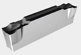
GM
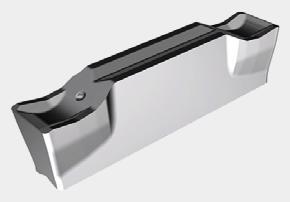
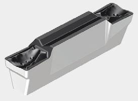
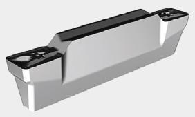
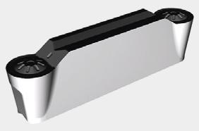
GH

1. Troncatura e scanalatura per acciai a basso tenore di carbonio e acciai inossidabili. Applied for parting o� & grooving on low carbon steels and stainless steels.
2. Troncatura materiali duttili, raccordi per tubi e parti a parete sottile, bassa forza di taglio. For sticky material, pipe fittings, thin-walled parts parting o�, low cutting force.
3. Avanzamento da basso a medio / For low to medium feed rate.
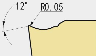
1. Troncatura e scanalatura per acciai legati e acciai inossidabili. Applied for parting o� and grooving on steels, alloy steel and stainless steels.
2. Bordo di taglio rinforzato / Reinforced cutting edge.
3. Avanzamento medio-alto / For medium to high feed rate.
TS

1. Inserto multifunzione esterno e interno per scanalatura, troncatura, scanalatura e tornitura frontale. Multifunctional insert for external, internal turning and grooving, parting o� and face grooving and face turning.
2. Eccellente controllo del truciolo / Excellent chip control.
3. Avanzamento da basso a medio / For low and medium feed rate.
TM

1. Inserto multifunzione esterno e interno per scanalatura, troncatura e tornitura frontale. Multifunctional insert for external, internal turning and grooving, parting o� and face grooving and face turning.
2. Preparazione del tagliente negativo / Negative edge preparation.
3. Avanzamento medio / For medium feed rate.
PM
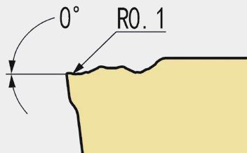
1. Troncatura, scanalatura e profilatura esterna / External, grooving, turning, profiling.
2. Avanzamento medio / Medium feed rate.
134
Inserti Inserts Geometria Geometry Preparazione del tagliente Cutting edge shape Descrizione Description
Scanalatura / Grooving
CHIP BREAKER
SCELTA E APPLICAZIONE CHOICE AND APPLICATION
Troncatura Parting o�
Scanalatura Grooving
Scanalatura esterna External grooving
Tornitura Turning
Profilatura Profiling
Sottosquadro Under cut
Scanalatura Grooving
Scanalatura anteriore Face grooving
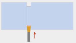
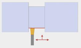
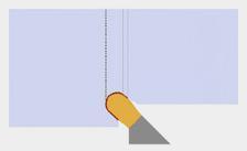
Tornitura Turning
Scanalatura Grooving
Scanalatura interna Internal grooving
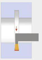
Tornitura Turning
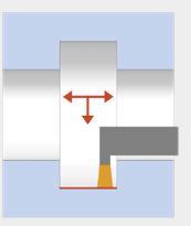
• Applicazione principale / First choice Applicazione secondaria / 2nd choice
Scelta degli inserti per applicazione Machining inserts selector
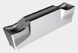
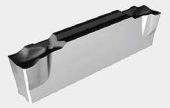
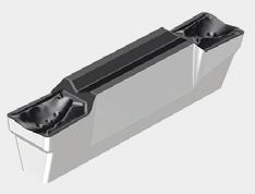
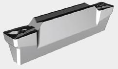

135
GGD GTD GH GM TS TM PM
• •
• • • •
• •
•
• •
• •
• •
• •
Inserti E ROMPITRUCIOLO INSERTS AND
INSERTI PER SCANALATURA GROOVING INSERTS Scanalatura / Grooving
INSERTI PER SCANALATURA GROOVING INSERTS
Gradi ISO
ISO grades
136
Gradi ISO inserti per scanalature / ISO Grooving grade Gruppi materiali Material groups Materiali Materials ISO Rivestimento / Coated PVD GP30BU P Acciai non legati e bassolegati Non-alloyed steel / Low Alloyed Acciaio legato Alloyed steel P01 P05 P10 P15 GP30BU P20 P25 P30 P35 P40 P45 P50 M
Acciaio inossidabile Duplex stainless steel
e altamente
stainless steel M01 M05 M10 M15 GP30BU M20 M25 M30 M35 M40 M45 K
grigia Grey cast iron
lamellare Nodular cast iron
malleabile Malleable cast iron K01 K05 K10 K15 GP30BU K20 K25 K30 K35 K40 K45 K50
Acciaio inossidabile austenitico Austenitic stainless steel Acciaio inossidabile molto tenace
legato Precipitation-hardening
Ghisa
Ghisa
Ghisa
Scanalatura / Grooving
137
• Applicazione principale / First choice Applicazione secondaria / 2nd choice Materiali / Materials Grado / Grade ISO Classificazione dei materiali Material classification AFNOR DIN Durezza Tensile strength (N / mm2) Durezza Hardness (HB) Rivestimento / Coated PVD GP30BU P Acciaio non legato Non-alloyed steel / Low alloyed S300 - 16NC6 9SMn36- 15CrNi6 < 600 < 180 • XC18 - 16NC6 Ck15 - 15NiCr6 < 950 < 280 • Acciaio legato Alloyed steel 42CD4 - XC60 42CrMo4 - Ck60 700 - 950 200 - 280 • Z40CDV4 X40CrMoV5 950 - 1200 280 - 355 • 55NCDV7 - Z40C14 55NiCrMoV6 X30Cr13 1200 - 1400 355 - 415 • M Acciaio inossidabile Duplex stainless steel Z2CNDN22.05 X2CrNiMoN22-5 778 230 • Acciaio inossidabile austenitico Austenitic stainless steel 304L - 316L - Z6CN18.09 304, 316, X6CrNi18-10 675 200 • Acciaio inossidabile molto tenace e altamente legato Precipitation hardening stainless steel Z3CNDN25.07Az X2CrNiMoN25 7 4 1013 300 • K Ghisa grigia Grey cast iron FT20D - FT40D GG20, GG40 700 220 Ghisa lamellare Nodular cast iron FGS400-12 - FGS700-2 GGG40, GGG70 880 260 Ghisa malleabile Malleable cast iron P540/5 GTS 55 04 800 250 S Superleghe a base di ferro Fe-based alloy Discalloy 943 280Superleghe a base di cobalto Co-based alloy Stellite 21 1076 320Superleghe a base di nichel Ni-based alloy Inconel 718 1177 350Lega di titanio Ti-alloy TiAl6V4 1262 370N Alluminio < 9% Aluminum < 9% A-U4SG AlCuSiMn 260 75Lega di alluminio Aluminum alloy A-S10G G-AlSi10Mg 447 130H Acciaio cementato, per utensili, temprato, al manganese, ecc. Hardened steel 100C6 - Z40CDV5 Z120M12 100Cr6 - X40CrMoV5 1 X120Mn12 50-60HRC 50-60HRCGhisa bianca Chilled cast iron Grado 2B Grade 2B FB Ni4 Cr2HC 55HRC 55HRC -
Scanalatura / Grooving
Scelta dei gradi Grade selector
INSERTI PER SCANALATURA GROOVING INSERTS
Parametri velocità di taglio
Cutting parameters
*I parametri di taglio devono essere regolati in base a fattori quali la rigidità della macchina, il corpo dell’utensile, le condizioni del pezzo e il refrigerante.
*Above chart for general cutting conditions. The actual selection should be adjusted according to factors such as machine rigidity, tool body, workpiece conditions and coolant.
138
Materiali / Materials Grado (rivestimento PVD) / Grade (PVD coating) ISO Classificazione dei materiali Material classification Durezza Tensile strength (N / mm2) Durezza Hardness (HB) GP30BU P15-35 M15-35 K15-35 Velocità di taglio consigliata in funzione del materiale e dell’operazione Cutting speed Vc (m/min) Scanalatura Troncatura Parting o� and Grooving Tornitura Turning min max min max P Acciaio non legato Non-alloyed steel / Low alloyed < 600 < 180 130 180 160 200 < 950 < 280 115 145 140 180 Acciaio legato Alloyed steel 700 - 950 200 - 280 100 130 120 160 950 - 1200 280 - 355 80 115 100 140 1200 - 1400 355 - 415 105 170 90 130 M Acciaio inossidabile Duplex stainless steel 778 230 85 135 110 170 Acciaio inossidabile austenitico Austenitic stainless steel 675 200 105 165 130 205 Acciaio inossidabile molto tenace e altamente legato Precipitation hardening stainless steel 1013 300 80 155 100 195 K Ghisa grigia Grey cast iron 700 220 95 185 120 230 Ghisa lamellare Nodular cast iron 880 260 80 145 95 180 Ghisa malleabile Malleable cast iron 800 250 65 115 80 145 S Superleghe a base di ferro Fe-based alloy 943 280 - - -Superleghe a base di cobalto Co-based alloy 1076 320 - - -Superleghe a base di nichel Ni-based alloy 1177 350 - - -Lega di titanio Ti-alloy 1262 370 - - -N Alluminio Aluminum 260 75 - - -Lega di alluminio Aluminum alloy 447 130 - - -H Acciaio cementato, per utensili, temprato, al manganese, ecc. Hardened steel - 50-60HRC - - -Ghisa bianca Chilled cast iron - 55HRC - - - -
Scanalatura / Grooving
INSERTI PER SCANALATURA GROOVING INSERTS
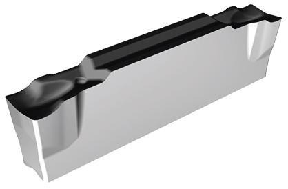
Inserto per scanalatura - GM
Troncatura e scanalatura per acciai a basso tenore di carbonio e acciai inossidabili.
Materiali duttili, raccordi per tubi e parti a parete sottile, bassa forza di taglio.
Avanzamento da basso a medio.
Inserts grooving - GM
Applied for parting o� & grooving on low carbon steel and stainless steel. For sticky material, pipe fittings, thin-walled parts, parting o�, low cutting force. For low to medium feed rate.
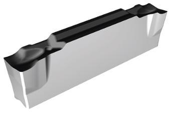
Inserto
scanalatura - GH
Troncatura e scanalatura acciaio, acciaio legato e inossidabile. Spigolo tagliente
Avanzamento e velocità: da medio ad alto.
Inserts grooving - GH
139 Scanalatura / Grooving
Parametri di taglio Cutting parameters Dimensioni (mm) Dimensions (mm) Articolo Reference Tipo Type Prof. Max. Max. depth Avanzamento Feed (mm/rev) W R L H Angolo di inclinazione Cutting edge angle Grado Grade Codice Code GGD 202-GM GP30BU-4MP Doppio bordo Double edge 19,7 0,04-0,15 2 0,2201,7 - GP30BU 67 064 925 GGD 202-GM-6R GP30BU-4MP Doppio bordo Double edge 19,7 0,04-0,15 2 0,2201,7 6° GP30BU 71 013 448 GGD 202-GM-15R GP30BU-4MP Doppio bordo Double edge 19,7 0,04-0,15 2 0,2201,7 15° GP30BU 71 013 456 GGD 302-GM GP30BU-4MP Doppio bordo Double edge 19,7 0,05-0,16 3 0,2202,4 - GP30BU 67 064 933 GGD 302-GM-6R GP30BU-4MP Doppio bordo Double edge 19,7 0,05-0,16 3 0,2202,4 6° GP30BU 71 013 464 GGD 302-GM-15R GP30BU-4MP Doppio bordo Double edge 19,7 0,05-0,16 3 0,2202,4 15° GP30BU 71 013 472 GGM 302-GM GP30BU-4MP Bordo singolo Single edge - 0,05-0,16 3 0,2202,4 - GP30BU 71 013 480
per
Applied for parting o� and grooving on steel, alloy steel and stainless steel. Strong cutting edge. For medium to high feed rate. Parametri di taglio Cutting parameters Dimensioni (mm) Dimensions (mm) Articolo Reference Tipo Type Prof. Max. Max. depth Avanzamento Feed (mm/rev) W R L H Grado Grade Codice Code GGD 202-GH GP30BU-4MP Doppio bordo Double edge 19,70,05-0,20 2 0,220 1,7 GP30BU 67 064 941 GGD 302-GH GP30BU-4MP Doppio bordo Double edge 19,70,06-0,27 3 0,2202,4 GP30BU 67 064 968 GGD 403-GH GP30BU-4MP Doppio bordo Double edge 19,70,08-0,30 4 0,320 3 GP30BU 67 064 976 GGM 302-GH GP30BU-4MP Bordo singolo Single edge - 0,06-0,27 3 0,2202,4 GP30BU 71 013 499 GGM 403-GH GP30BU-4MP Bordo singolo Single edge - 0,08-0,30 4 0,320 3 GP30BU 71 013 502 7° H R L W 7 H R L W
02
Scanalatura, inserti per scanalatura Grooving inserts
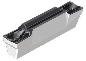
Scanalatura, inserti per scanalatura Grooving inserts
Inserto per scanalatura/ tornitura - TS
Inserto multifunzione: tornitura esterna e interna, troncatura, scanalatura e scanalatura frontale.
Rompitrucioli per sgrossatura.
Velocità di avanzamento bassa e media.
Parametri di taglio
Cutting parameters
Scanalatura Grooving Tornitura Turning
Prof. Max. Max. depth
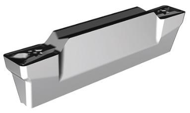
Inserto per scanalatura/ tornitura - TM
Inserto multifunzione: tornitura esterna e interna, troncatura, scanalatura e scanalatura frontale. Rompitrucioli per sgrossatura. Velocità di avanzamento medio-alta.
Parametri di taglio
Cutting parameters
Insert grooving / turning - TS
Multifunctional insert for external, internal turning and grooving, parting o� and face grooving and face turning. Heavy duty chipbreakers. For low and medium feed rate.
Dimensioni (mm)
Dimensions (mm)
Insert grooving / turning - TM
Multifunctional insert for external, internal turning and grooving, parting o� and face grooving and face turning. Heavy duty chipbreakers. For medium feed rate.
Dimensioni (mm)
Dimensions (mm)
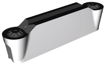
140 Scanalatura / Grooving
Articolo Reference Tipo Type Avanzamento Feed (mm/rev) Avanzamento Feed (mm/rev) Ap (mm) W R L H Grado Grade Codice Code GTD 303-TS GP30BU-4MP Doppio bordo Double edge 19,7 0,05-0,250,15-0,230,45-2,030,3202,2GP30BU67 064 984 GTD 404-TS-GP30BU-4MP Doppio bordo Double edge 19,7 0,06-0,270,18-0,250,5-2,540,4203GP30BU67 064 992 GTD 408-TS GP30BU-4MP Doppio bordo Double edge 19,7 0,06-0,270,18-0,251,0-2,540,8203GP30BU67 065 018 7° H R L W
Articolo Reference Tipo Type Avanzamento Feed (mm/rev) Avanzamento Feed (mm/rev) Ap (mm) W R L H Grado Grade Codice Code GTD 304-TM GP30BU-4MP Doppio bordo Double edge 19,7 0,10-0,250,15-0,220,5-2,030,4202,2GP30BU67 065 026 GTD 404-TM-GP30BU-4MP Doppio bordo Double edge 19,7 0,15-0,300,18-0,270,5-2,540,4203GP30BU67 065 034 GTD 408-TM GP30BU-4MP Doppio bordo Double edge 19,7 0,15-0,300,18-0,271,0-2,540,8203GP30BU67 065 042 7° H R L W Inserto per scanalatura/ tornitura - PM Inserto tondo per tornitura esterna, scanalatura e profilatura. Velocità media di avanzamento. Insert grooving / turning - PM Round insert applied for external turning, grooving and profiling. Medium feed rate.
Cutting parameters Dimensioni (mm) Dimensions (mm) Scanalatura Grooving Tornitura Turning Articolo Reference Type Type Avanzamento Feed (mm/rev) Avanzamento Feed (mm/rev) Ap (mm) W R L H Grado Grade Codice Code GTD 210-PM GP30BU-4MP Doppio bordo Double edge 0,06-0,15 0,12-0,25 0,4-1,0 2 1 20 1,7GP30BU67 065 050 GTD 315-PM GP30BU-4MP Doppio bordo Double edge 0,08-0,18 0,15-0,30 0,5-1,5 3 1,5 20 2,2GP30BU67 065 069 GTD 420-PM GP30BU-4MP Doppio bordo Double edge 0,10-0,20 0,18-0,350,6-2,0 4 2 20 3 GP30BU 67 065 077 7° H R L W
Prof. Max. Max. depth Scanalatura Grooving Tornitura Turning
Parametri di taglio
02
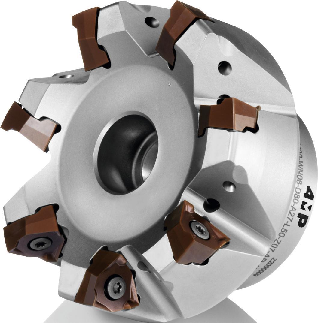
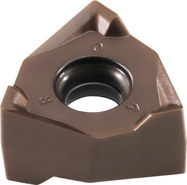
Fresatura / Milling 02
MILLING 169 Informazioni tecniche Technical Information 142 Gamma dei corpi fresa Milling toolholders overview 144 Codifica Designation system 145 Codifica Designation system 146 Gradi ISO ISO grades 147 Scelta dei gradi e dei parametri di taglio Grades & cutting parameters selector 150 Scelta dei rompitrucioli Chip breaker selector 152 Porta-inserti, inserti e condizioni d’uso Toolholders, inserts and conditions of use 170 Tabella delle equivalenze dei gradi di fresatura Milling grade conversion table Corpo fresa Milling toolhoders Fresatura Milling Inserti per fresatura Miling inserts 141
FRESATURA
Gamma dei corpi fresa
Milling toolholders overview
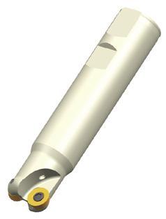
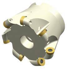
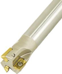
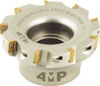
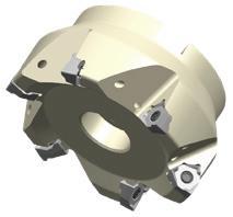
142 Fresatura / Milling Pagina del catalogo: Catalog page P152 P152 P154 P154 P156 Serie Series MPE/FP00-RD12 MPE/FM90-AP10/16 MPE/FM90-WN08 Angolo di attacco / Approach angle - 90° 90° Profondità massima di passata (mm) / Max. depth of cut (mm) 6 10/16 7 Gamma diametri (mm) / Diameter range (mm) Ø25-Ø32 Ø52-Ø66 Ø16-Ø32 Ø40-Ø100 Ø50-Ø125 Designazione dell’inserto / Insert designation RD..12T3.. AP..1003 / AP16..04 WN..0806.. Applicazione / Application Spianatura Face milling O O O O O Fresatura di spallamento Shoulder milling O O O Scanalatura Slot milling O O O Fresatura in rampa Ramping O O O O Interpolazione elicoidale Helical milling O O O O Trafilatura Plunging O O O Fresatura di profili Profile milling O O Smussatura Chamfer milling Lavorazione tasca Pocket machining O O Scelta numero 1 Best choice
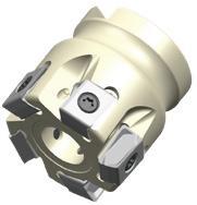
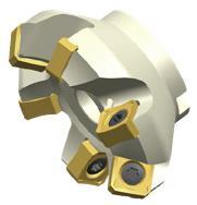
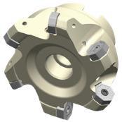
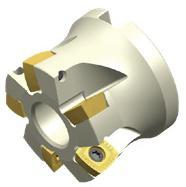
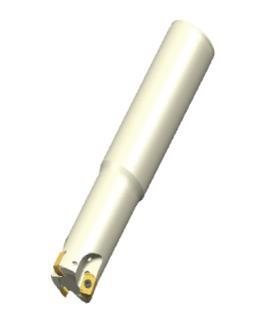
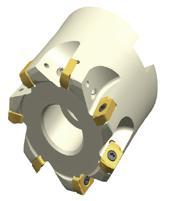
Fresatura / Milling 143
Pagina del catalogo: Catalog page P158 P160 P162 P163 P166 P166 Serie Series MPE/FM90-LN13 MPFF45-SN12 MPE/FF45-XN07 MPFH15-XD12 MPE/FH20-LN06...C Angolo di attacco / Approach angle 90° 45° 45° 15° 20° Profondità massima di passata (mm) / Max. depth of cut (mm) 12 6,5 4 2,5 1 Gamma diametri (mm) / Diameter range (mm) Ø40-Ø100 Ø50-Ø160 Ø40-Ø160 Ø52-Ø125 Ø17-Ø33 Ø40 Designazione dell’inserto / Insert designation LN..1306..SN..1206.. XN..0705..XD..1205.. LN..06C Applicazione / Application Spianatura Face milling O O O O O O Fresatura di spallamento Shoulder milling O Scanalatura Slot milling O O Fresatura in rampa Ramping O O O Interpolazione elicoidale Helical milling O O O Trafilatura Plunging O Fresatura di profili Profile milling Smussatura Chamfer milling Lavorazione tasca Pocket machining O O
Gamma dei corpi fresa Milling toolholders overview
144 Fresatura / Milling Lunghezza del tagl�ente Length of cutt�ng edge 7 D�ametro d� tagl�o: D Cutt�ng d�ameter : D 8 Lunghezza totale: L Total length : L 10 Numero d� dent�: Z Number of teeth : Z 11 A: Codolo A : Shank
Gambo Weldon
: Weldon shank C: Gambo c � l � ndr � co C : Cyl � ndr � cal shank T�po e d�ametro dell’attacco Connect�on and D�ameter 9 N: Gambo Wh � stle notch N : Wh � stle notch shank M: Gambo f � lettato M : Screw clamped w � th modular head Angolo d� spogl�a �nserto Clearance angle 6 G N P D E F A B C E - Codolo E - Shank Attacco Attachment 2 F - Alesatura F - Arbor Angolo d� attacco Approach angle 4 90° - 75° - 60° - 45° - 20° - 15° - 11° - 5° - 0° D16 8 W16 9 Z02 11 L100 10 H 12 90 4 A 5 MP E 2 P 6 10 7 4MP Codifica Designation system M 3 Refr�geraz�one Coolant 12 A o/or H: Con passagg � o d � refr � gerante A ou/or H : Internal coolant N: Nessuna refr � geraz � one N : No coolant M : Fresa per sp � anatura M : Shoulder m � ll � ng F : Fresa per sp � anatura F : Face m � ll � ng P : Fresa per prof � latura P : Prof � le m � ll � ng T�po Type 3 H : Fresa ad alto avanzamento H : H � gh feed m � ll � ng T : Fresa per f � lettare T : Thread m � ll � ng T : Fresa per smuss � T : Chamfer m � ll � ng R: Destra R : R � ght L: S � n � stra L : Left Senso d� rotaz�one Cutt�ng d�rect�on 13 N: Neutro N : Neutral N: Nuovo N : New Var� Others 14 T�po d� �nserto Insert Type H M O P L R S T V W A B C D E K 5
MILLING TOOLHOLDERS
W:
W
CORPO FRESA
/ Corner radius MO = Inserto tondo / Round insert (metric)
145 Fresatura / Milling Codifica Designation system LSP 10 E 8 R 9 T 4 L 3 D 2 X 1 08 7 05 6 12 5 Angolo d� spogl�a Clearance angle 2 C D E F G N P O Altro angolo d �� spogl � a Other clearance angle 11° 20° 25° 30° 0° 7° 15° T�po d� �nserto Clamp�ng Type 4 A B C F G H J M N O R T U W Z 70°-90° 70°-90° 70°-90° 70°-90° Spec � ale Spec � al 40°-60° 40°-60° 40°-60° Romp�truc�olo Ch�p breaker 10 Vedi pagina XXX Refer to page XXX Forma Shape 1 85° 86° 86° 135° 120° A H M O R S T Z 90° 360° 60° Spec � ale Spec � al X Tolleranza Tolerance 3 Classe / Class Tolleranza / Tolerance d m s A ± 0,025 ± 0,005 ± 0,025 F ± 0,013 C ± 0,025 ± 0,013 H ± 0,013 E ± 0,025± 0,025 G ± 0,13 J ± 0,05 a ± 0,15 ± 0,005 ± 0,025 K ± 0,13 L ± 0,025 M ± 0,08 a ± 0,20 ± 0,13 N ± 0,025 U ± 0,08/0,25 ± 0,13± 0,13 01 = 1.59 T1 = 1.98 02 = 2.38 T2 = 2.78 03 = 3.18 T3 = 3.97 04 = 4.76 05 = 5.56 06 = 6.35 07 = 7.94 09 = 9.52 Spessore / Th�ckness 6 In. D�mens�one del cerch�o (mm) In. C�rcle D�mens�on (mm) Forma � nsert � / Insert shape H M O R S T Z 3,18 05 4,0 06 5 05 5,6 09 6 06 6,4 11 7,94 13 8,0 08 9,5 09 09 16 10 10 12 12 12,7 04 12 12 22 15,875 15 15 27 16,0 06 16 19,1 19 19 33 20 20 25 25 25 25,4 25 31,8 31 32,0 32
Cutt�ng edge length 5 Codice
negativi Negative land D Bordi onati Double negative land S Bordi levigati e negativi Negative land + Honed cutting edge P Doppi angoli arrotondati e negativi Doubles negative land + Honed cutting edge Preparaz�one del
Edge preparat�on
8
00
Sharp 01
0.1 02 = 0.2 04 = 0.4 08 = 0.8 12 = 1.2 16 = 1.6 20 = 2.0 24 = 2.4 28 = 2.8 32 = 3.2 40 = 4.0 48 = 4.8 56 = 5.6 64 = 6.4 X = Altri / Others Smussare / Wiper nose 1º lettera / 1 st letter (Kr)2e lettera / 2 nd letter (n) A = 45° D = 60° E = 75° F = 85° G = 87° P = 90° Z = Altri / Others A = 3° B = 5° C = 7° D = 15° E = 20° F = 25° G = 30° N = 0° P = 11° Z = Altri / Others Ragg�o dell’�nserto / Tool nose 7 R Kr n R L N Rotazione a sinistra / Right hand Rotazione a sinistra / Left hand Rotazione a destra o a sinistra / Neutral hand Senso d� rotaz�one / Hand of tool 9 1
Lunghezza del tagl�ente
Code Angolo della spoglia / Edge shape Disegno / Illustration V Bordo a�lato Sharp cutting edge E Bordi levigati Honed cutting edge C Angoli
tagl�ente (�ns. pos�t�v�)
(pos�t�ve �nserts)
Raggio
= Spigolo vivo /
=
INSERTI PER FRESATURA MILLING INSERTS
146
Gradi di fresatura ISO / Milling grade ISO group Gruppi materiali Material group Materiali / Materials ISO PVD PVD PVD PVD CVD CVD PVD Non rivestito Uncoated ISO MP15BH MP30BM / MP25BM MP35BMMP40BMMC30BPMC30BKMP25BK MN10AA / MN10AK P Acciaio non legato Non-alloyed steel / Low Alloyed Acciaio legato Alloyed steel P01 P01 P05 P05 P10 P10 P15 MP30BM / MP25BM P15 P20 MP40BM P20 P25 MC30BP P25 P30 MP35BM P30 P35 P35 P40 P40 P45 P45 P50 P50 M Acciaio inossidabile Stainless steel M01 M01 M05 M05 M10 M10 M15 MP30BM / MP25BM M15 M20 MP40BM M20 M25 MC30BP M25 M30 MP35BM M30 M35 M35 M40 M40 M45 M45 K Ghise Cast iron K01 K01 K05 K05 K10 MP15BH MC30BK K10 K15 MP25BK K15 K20 K20 K25 K25 K30 K30 K35 K35 K40 K40 K45 K45 K50 K50 S Superleghe High temperature alloys S01 S01 S05 S05 S10 S10 S15 S15 S20 MC30BK S20 S25 S25 S30 MC30BP S30 S35 S35 S40 S40 S45 S45 N Alluminio Aluminum alloys N01 N01 N05 MN10AA / MN10AK N05 N10 N10 N15 N15 N20 N20 N25 N25 N30 N30 H Acciaio cementato, per utensili, temprato, al manganese, ecc. Hardened steel Ghisa bianca Chilled cast iron H01 H01 H05 H05 H10 MP15BH H10 H15 H15 H20 H20 H25 H25 H30 H30
Fresatura / Milling
Gradi ISO ISO grades
INSERTI PER FRESATURA MILLING INSERTS
DEI GRADI DI FRESATURA
MILLING GRADE DESCRIPTION
MP25BM: Rivestimento PVD / coating
Nuovo rivestimento PVD, prima scelta per la fresatura degli acciai.
Substrato in carburo a micrograna con struttura uniforme, elevata durezza, eccellente resistenza all’usura e alla fissurazione termica.
Evoluzione del grado MP30BM per ridurre notevolmente la scheggiatura e l’usura periferica.
New PVD coating, first choice for steel milling.
Super-fine grain carbide substrate, with uniform grain structure, high hardness, good strength and thermal crack resistance. Evolution of the MP30BM grade to considerably reduce built-up edge and peripheral wear.
MP35BM: Rivestimento PVD / coating
Rivestimento PVD, per la fresatura di acciai, acciai inossidabili e leghe resistenti al calore.
Substrato in carburo ad alta resistenza con rivestimento PVD nanostrutturato, elevata adesione del rivestimento.
Grado tenace consigliato per applicazioni di semifinitura e sgrossatura.
PVD coating , for steel, stainless steel and high-temp alloy milling.
High strength carbide substrate with nanostructured PVD coating, high coating adhesion.
Tough grade recomanded for semi-finishing and roughing application.
MP40BM: Rivestimento PVD / coating
Rivestimento PVD, per la fresatura di acciai, acciai inossidabili e leghe resistenti al calore.
Prima scelta per la fresatura di acciai inossidabili.
Substrato in carburo ad alta resistenza con rivestimento PVD nanostrutturato, elevata adesione del rivestimento.
PVD coating, for steel, stainless steel and high-temp alloy milling.
First choice for stainless steel milling.
High strength carbide substrate with nanostructured PVD coating, high coating adhesion.
MP15BH: Rivestimento PVD / coating
Nuovo rivestimento PVD, prima scelta per la fresatura degli acciai duri.
Ottima resistenza all’usura e resistenza alla propagazione delle cricche. Il rivestimento ha un’elevata durezza e un’eccezionale resistenza all’ossidazione. La superficie liscia del rivestimento riduce la forza di taglio.
New PVD coating, first choice for hard steel milling.
Excellent wear resistance and crack propagation resistance. The coating has high hardness and outstanding oxidation resistance.
Smooth coating surface reduces cutting force.
MP25BK: Rivestimento PVD / coating
Rivestimento PVD, per la fresatura delle ghise.
Il substrato ha una struttura a grana uniforme, con elevata durezza ed elevata resistenza all’usura. Grado utilizzato per la spianatura, la fresatura di spallamenti e la fresatura ad avanzamenti elevati.
Adatto per elevate prestazioni a umido e a secco nelle operazioni di fresatura di materiali in ghisa.
PVD coating, for cast iron milling.
The substrate has uniform grain structure, with high hardness and high wear resistance.
This grade is used for face milling, shoulder milling, high feed mil ling.
Suitable for dry and wet high-performance milling of cast iron materials.
MC30BP: Rivestimento CVD / coating
Rivestimento CVD, per fresatura semifinitura di acciai e acciai inossidabili.
Substrato in carburo ad alta resistenza con rivestimento CVD multistrato, elevata adesione del rivestimento, resistenza all’usura, eccellente stato della superficie.
CVD coating, for semi-finishing in steel and stainless steel milling.
High strength carbide substrate with multi-layer CVD coating, high coating adhesion, wear resistance and surface finish quality.
MC30BK: Rivestimento CVD / coating
Rivestimento CVD, per fresatura di finitura, semifinitura e sgrossatura di ghisa grigia e nodulare.
Substrato in carburo ad alta resistenza con rivestimento CVD multistrato, elevata adesione del rivestimento, resistenza all’usura. CVD coating, for gray and nodular cast iron finish, semi-finish and rough milling.
High strength and wear resistance carbide substrate with multi-layer CVD coating.
MN10AK: Non rivestito / Uncoated
Substrato in carburo a grana fine non rivestito con tagliente trattato in modo speciale.
Adatto per la fresatura di metalli non ferrosi in varie condizioni di taglio.
Uncoated fine grain carbide substrate with special treated cutting edge.
Suitable for non ferrous metal milling under various cutting conditions.
147
DESCRIZIONE
Fresatura / Milling
Tabella 1 / Table 1
Scelta dei gradi e dei parametri di taglio
Grades and cutting parameters selector
Gradi di fresatura / Milling grades application range
CVD rivestito Coated CVD rivestito Coated PVD rivestito Coated Non rivestito Uncoated
*I parametri di taglio e�ettivi devono essere regolati in base a fattori quali la rigidità della macchina, il corpo dell’utensile, le condizioni del pezzo e il refrigerante.
*Above chart for general cutting conditions. The actual selection should be adjusted according to factors such as machine rigidity, tool body, workpiece conditions and coolant.
148
Materiali / Materials MC30BP MC30BK MP25BK MN10AA / MN10AK ISO Classificazione dei materiali Material classification AFNOR DIN Durezza Tensile strength (N/mm2) Durezza Hardness (HB) P25-40 - -M25-40 - -- K10-35 K15-35- -- - - N05-15 - - -Impegno radiale / Cutting width (%) 10%20%100%10%20%100%10% 20%100%10%20%100% Velocità di taglio / Cutting speed m/min P Acciaio non legato Non-alloyed steel Low Alloyed S300 - 16NC6 9SMn36- 15CrNi6 <600 <180 350250200 XC18 - 16NC6 - Ck15 - 15NiCr6 - <950 <280270180 120 Acciaio legato Alloyed steel 42CD4 - XC60 42CrMo4 - Ck60,700-950 200-280290240200 Z40CDV4 X40CrMoV5, 950-1200 280-355260200150 55NCDV7 - Z40C1455NiCrMoV6 - X30Cr131200-1400355-415200160 110 M Acciaio inossidabile Duplex stainless steel Z2CNDN22.05 X2CrNiMoN22-5, 778 230 Acciaio inossidabile austenitico Austenitic stainless steel 304L - 316L - Z6CN18.09304, 316, X6CrNi18-10675 200 Acciaio inossidabile molto tenace e altamente legato Precipitation-hardening stainless steel Z3CNDN25.07Az X2CrNiMoN25 7 4 1013 300 K Ghisa grigia Grey cast iron FT20D - FT40D GG20, GG40, 700 220 480310 140 310 280240 Ghisa lamellare Nodular cast iron FGS400-12 - FGS700-2GGG40, GGG70, 880 260 450295 140 280 250220 Ghisa malleabile Malleable cast iron P540/5 GTS 55 04 800 250 500365 230 240 200170 S Superleghe a base di ferro Fe-based alloy Discalloy 943 280 Superleghe a base di cobalto Co-based alloy Stellite 21 1076 320 Superleghe a base di nichel Ni-based alloy Inconel 718 1177 350 Lega di titanio / Ti-alloy TiAl6V4 1262 370 N Alluminio < 9% Aluminum < 9% A-U4SG AlCuSiMn 260 75 600600 500 Lega di alluminio Aluminum alloy A-S10G G-AlSi10Mg 447 130 280280 200 H Acciaio cementato, per utensili, temprato, al manganese, ecc. Hardened steel 100C6 - Z40CDV5Z120M12 100Cr6 - X40CrMoV5 1 -X120Mn12 50-60HRC50-60HRC Ghisa bianca Chilled cast iron Grado 2B Grade 2B FB Ni4 Cr2HC 55HRC55HRC
Fresatura / Milling
Tabella 2 / Table 2
Scelta dei gradi e dei parametri di taglio
Grades and cutting parameters selector
149 Gradi di fresatura / Milling grades application range PVD rivestito / Coated Materiali / Materials MP30BM / MP25BM MP35BM MP40BM MP15BH ISO Classificazione dei materiali Material classification AFNOR DIN Durezza Tensile strength (N/mm2) Durezza Hardness (HB) P15-35 P30-45 P20-40M15-35 M30-45 M20-40- - - K10-K20 - S30-45 S20-40- - -- - - H10-H20 Impegno radiale / Cutting width (%) 10% 20%100% 10% 20%100% 10% 20%100% Velocità di taglio / Feed mm/rev P Acciaio non legato Non-alloyed steel Low Alloyed S300 - 16NC6 9SMn36- 15CrNi6 <600 <180 290 240 200 230 205 170 XC18 - 16NC6 - Ck15 - 15NiCr6 - <950 <280 210 170 130 200 180 160 Acciaio legato Alloyed steel 42CD4 - XC60 42CrMo4 - Ck60,700-950 200-280250 210 160 200 155 110 Z40CDV4 X40CrMoV5, 950-1200 280-355230 190 140 180 130 90 55NCDV7 - Z40C1455NiCrMoV6 - X30Cr131200-1400355-415190 150 110 140 105 70 M Acciaio inossidabile Duplex stainless steel Z2CNDN22.05 X2CrNiMoN22-5, 778 230 170 140 110 160 130 100 150 130 110 Acciaio inossidabile austenitico Austenitic stainless steel 304L - 316LZ6CN18.09 304, 316, X6CrNi18-10675 200 180 150 120 170 140 110 160 140 105 Acciaio inossidabile molto tenace e altamente legato Precipitation-hardening stainless steel Z3CNDN25.07Az X2CrNiMoN25 7 4 1013 300 160 130 100 150 120 90 140 120 90 K Ghisa grigia Grey cast iron FT20D - FT40D GG20, GG40, 700 220 100-300 Ghisa lamellare Nodular cast iron FGS400-12FGS700-2 GGG40, GGG70, 880 260 100-300 Ghisa malleabile Malleable cast iron P540/5 GTS 55 04 800 250 100-300 S Superleghe a base di ferro Fe-based alloy Discalloy 943 280 75 60 50 Superleghe a base di cobalto Co-based alloy Stellite 21 1076 320 60 50 35 Superleghe a base di nichel Ni-based alloy Inconel 718 1177 350 60 50 35 Lega di titanio / Ti-alloy TiAl6V4 1262 370 50 40 30 N Alluminio < 9% Aluminum < 9% A-U4SG AlCuSiMn 260 75 Lega di alluminio Aluminum alloy A-S10G G-AlSi10Mg 447 130 H Acciaio cementato, per utensili, temprato, al manganese, ecc. Hardened steel 100C6 - Z40CDV5Z120M12 100Cr6 - X40CrMoV5 1 -X120Mn12 50-60HRC 5060HRC 30-80 Ghisa bianca Chilled cast iron Grado 2B Grade 2B FB Ni4 Cr2HC 55HRC55HRC 30-80
parametri di taglio e�ettivi devono essere regolati in base a fattori quali la rigidità della macchina, il corpo dell’utensile, le condizioni del pezzo e il refrigerante.
*I
*Above chart for general cutting conditions. The actual selection should be adjusted according to factors such as machine rigidity, tool body, workpiece conditions and coolant.
Fresatura / Milling
Materiali / Materials
ISO Classificazione dei materiali Material
classification AFNOR DIN
Acciaio non legato
Non-alloyed steel
Scelta dei rompitrucioli
Chip breaker selector
Rompitruciolo per fresatura / Milling chip breaker
AAA / LAALSP GPM GPH MPK RPK RKK
Lavorazione pesante di sgrossatura Heavy roughing machining P
Durezza Tensile strength (N/mm2)
Durezza Hardness (HB)
Alluminio machining aluminium alloy
Lavorazione leggera Light cutting machining Lavorazione generica
General type
Scelta di base / Best choice
Scelta N.2 / 2nd choice
*I parametri di taglio e�ettivi devono essere regolati in base a fattori quali la rigidità della macchina, il corpo dell’utensile, le condizioni del pezzo e il refrigerante.
*Above chart for general cutting conditions. The actual selection should be adjusted according to factors such as machine rigidity, tool body, workpiece conditions and coolant.
Lavorazione media Medium machining Sgrossatura Roughing machining
150
/ Low Alloyed S300 - 16NC6 9SMn36- 15CrNi6 <600 <180-XC18 - 16NC6 Ck15 - 15NiCr6 <950 <280 - -Acciaio legato Alloyed steel 42CD4 - XC60 42CrMo4 - Ck60 700-950 200-280 -Z40CDV4 X40CrMoV5 950-1200 280-355 -55NCDV7 - Z40C1455NiCrMoV6 - X30Cr131200-1400355-415 -M Acciaio inossidabile Duplex stainless steel Z2CNDN22.05 X2CrNiMoN22-5, 778 230 - - -Acciaio inossidabile austenitico Austenitic stainless steel 304L - 316L - Z6CN18.09304, 316, X6CrNi18-10 675 200 - - -Acciaio inossidabile molto tenace e altamente legato Precipitation-hardening stainless steel Z3CNDN25.07Az X2CrNiMoN25 7 4 1013 300 - - -K Ghisa grigia Grey cast iron FT20D - FT40D GG20, GG40 700 220 -Ghisa lamellare Nodular cast iron FGS400-12 - FGS700-2GGG40, GGG70 880 260 -Ghisa malleabile Malleable cast iron P540/5 GTS 55 04 800 250 -S Superleghe a base di ferro / Fe-based alloy Discalloy 943 280 - - -Superleghe a base di cobalto / Co-based alloy Stellite 21 1076 320 - - -Superleghe a base di nichel / Ni-based alloy Inconel 718 1177 350 - - -Lega di titanio Ti-alloy TiAl6V4 1262 370 - - -N Alluminio < 9% Aluminum < 9% A-U4SG AlCuSiMn 260 75 - - - - -Lega di alluminio Aluminum alloy A-S10G G-AlSi10Mg 447 130 - - - - -H Acciaio cementato, per utensili, temprato, al manganese, ecc. Hardened steel 100C6 - Z40CDV5Z120M12 100Cr6 - X40CrMoV5 1 -X120Mn12 50-60HRC50-60HRC - - - - -Ghisa bianca Chilled cast iron Grado 2B Grade 2B FB Ni4 Cr2HC 55HRC55HRC - - - - - -Fresatura / Milling
Geometria inserto / Insert geometry
AAA
LSP
GPM / GPH
MPK
Rompitruciolo / Edge shape
RPK
RKK
PDER-IT
PDER
Geometrie di fresatura
Milling geometries introduction
Applicazione / Application
• Bassa forza di taglio, per lavorazione leggera
Low cutting force, for weak machining condition
• Geometria positiva
Sharp geometry
• Per la lavorazione dell’alluminio
For aluminium material machining
• Bassa forza di taglio, per lavorazione leggera
Low cutting force, for weak machining condition
• Geometria positiva
Sharp geometry
• Per la lavorazione di acciai, acciai inossidabili e superleghe
For steel, stainless-steel and heat resistant alloy machining
1º scelta / 1st choice
• Per lavorazioni in condizioni medie
For medium machining condition
• Geometria universale
Universal geometry
• Per la lavorazione della maggior parte dei materiali
For machining most materials
• Per lavorazioni in condizioni da medie a buone
For medium or better machining condition
• Geometria universale
Universal geometry
• Per la lavorazione della maggior parte dei materiali
For machining most materials
• Per lavorazioni in condizioni stabili
For stable machining condition
• Geometria rinforzata per sgrossatura
Roughing geometry
• Per la lavorazione della maggior parte dei materiali
For machining most materials
• Per lavorazioni in condizioni stabili
For stable machining condition
• Geometria rinforzata per sgrossatura
Heavy roughing geometry
• Per la lavorazione di ghisa e acciai
Mainly for cast iron and steel machining
• A�latura dei taglienti, geometria positiva, per inserti specifici
Sharp geometry, for specified product
• Geometria universale, per inserti specifici
Universal geometry, for specified product
151
Fresatura / Milling
Fresatura, portautensili, inserti e condizioni d’uso Milling, toolholders, inserts and conditions of use
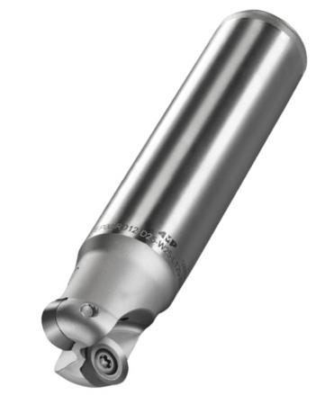
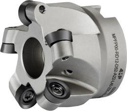
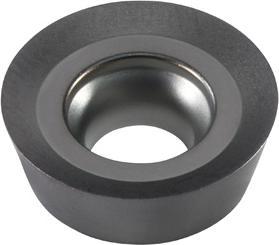
152 Fresatura / Milling Articolo Reference D d1 L l1 Ap max Refrigerazione Internal coolant Z Ins. Insert N. taglienti Insert : nb of edges Codice Code MPEP00-RD12-D25-W25-L120-Z02-AR-4MP 25 25 120 30 6 O 2 RD..12T3 - 67 061 233 MPEP00-RD12-D32-W32-L120-Z03-AR-4MP 32 32 120 40 6 O 3 RD..12T3 - 67 061 241 Corpo fresa per profilatura MPEP00-RD12 Profile milling cutter MPEP00-RD12 Corpo fresa per profilatura MPFP00-RD12 Profile milling cutter MPFP00-RD12 Articolo Reference D d1 L l1 Ap max Refrigerazione Internal coolant Z Ins. insert N. taglienti Insert : nb of edges Codice Code MPFP00-RD12-D52-A22-L40-Z05-AR-4MP 52 22 40 - 6 O 5 RD..12T3 - 67 061 276 MPFP00-RD12-D66-A27-L50-Z06-AR-4MP 66 27 50 - 6 O 6RD..12T3 - 67 061 268 Dimensioni (mm) Dimensions (mm) Gruppo materiali ISO / Material group Articolo Reference Rompitruciolo da 4 MP Chip breaker 4MP l d s r b P M K S N H Codice Code RDHT 12T3MOE-LSP MC30BP-4MP RDHT 12T3MOE-LSP - 123,97- - • 67 063 775 RDHT 12T3MOE-LSP MC30BK-4MP RDHT 12T3MOE-LSP - 123,97- - • 67 063 783 RDHT 12T3MOE-LSP MP25BM-4MP RDHT 12T3MOE-LSP - 123,97- - • 71 170 969 RDHT 12T3MOE-LSP MP35BM-4MP RDHT 12T3MOE-LSP - 123,97- - • • 67 063 805 Inserti RD12… Inserts RD12… Diametro fresa (mm) Cutter diameter (mm) Vite Screw Chiave di serraggio Wrench Coppia di serraggio Torque Ø25-80 4,0 Nm Articolo Reference Codice Code Articolo Reference Codice Code MPSP040090-4MP 67 064 240 MPDT-TP15-4MP 67 064 216 Accessori Accessories Applicazione principale / First choice Applicazione secondaria / Second choice
02
Fresatura,
Avanzamento e profondità a seconda del materiale e del rompitruciolo
Advance and depth depending on material and chip breaker
*I parametri di taglio e�ettivi devono essere regolati in base a fattori quali la rigidità della macchina, il corpo dell’utensile, le condizioni del pezzo e il refrigerante.
153 Fresatura / Milling
ISO Classificazione dei materiali Material classification AFNOR DIN Durezza Tensile strength (N / mm2) Durezza Hardness (HB)
RD12T3 Sgrossatura Roughing Lavorazione media Medium machining Finitura Finishing Ap (mm)fz (mm/dts)Ap (mm)fz (mm/dts)Ap (mm) fz (mm/dts) mm min max min max min max min max min max min max P Acciaio non legato Non-alloyed steel Low Alloyed S300 - 16NC6 9SMn36 15CrNi6 < 600 < 180 3,00 6,00 0,250,40 0,803,00 0,220,32 0,100,80 0,100,18 XC18 - 16NC6 Ck15 15NiCr6 < 950 < 280 Acciaio legato Alloyed steel 42CD4 - XC60 42CrMo4 Ck60, 700 - 950 200 - 280 3,006,000,220,35 0,200,30 0,100,16 Z40CDV4 X40CrMoV5950 - 1200 280 - 355 55NCDV7 Z40C14 55NiCrMoV6 X30Cr13 1200-1400355-415 M Acciaio inossidabile Duplex stainless steel Z2CNDN22.05 X2CrNiMo N22-5 778 230 0,080,16 0,08 0,12 -Acciaio inossidabile austenitico Austenitic stainless steel 304L - 316L Z6CN18.09 304, 316 X6CrNi18-10 675 200 0,080,14 0,08 0,10 Acciaio inossidabile molto tenace e altamente legato Precipitation hardening stainless steel Z3CNDN25.07Az X2CrNiMo N25 7 4 1013 300 K Ghisa grigia Grey cast iron FT20D - FT40D GG20 GG40 700 220 0,200,30 0,100,16 3,006,000,220,35 Ghisa lamellare Nodular cast iron FGS400-12 FGS700-2 GGG40 GGG70 880 260 Ghisa malleabile Malleable cast iron P540/5 GTS 55 04 800 250 S Superleghe a base di ferro Fe-based alloy Discalloy 943 280 - 0,060,12 0,08 0,12 Superleghe a base di cobalto Co-based alloy Stellite 21 1076 320 Superleghe a base di nichel Ni-based alloy Inconel 718 1177 350 Lega di titanio Ti-alloy TiAl6V4 1262 370 N Alluminio < 9% Aluminum < 9% A-U4SG AlCuSiMn 260 75 0,050,14 0,06 0,12 3,006,000,060,12 Lega di alluminio Aluminum alloy A-S10G G-AlSi10Mg 447 130 H Acciaio per utensili temprato al manganese Hardened steel 100C6 - Z40CDV5 Z120M12 100Cr6X40Cr Mov5 1X120Mn12 50-60HRC50-60HRC - - 0,50 1,00 0,050,080,100,50 0,030,05 Ghisa bianca Chilled cast iron Grado 2B Grade 2B FBNi4 Cr2HC 55HRC 55HRC
corpi fresa, inserti e condizioni d’uso Milling, toolholders, inserts and conditions of use 02
Profondità di taglio e avanzamento / Cutting depth and feed
*Above chart for general cutting conditions. The actual selection should be adjusted according to factors such as machine rigidity, tool body, workpiece conditions and coolant.
02
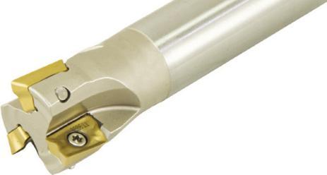
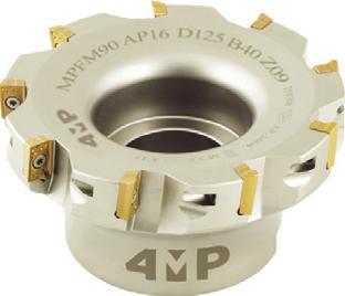
Fresatura, corpi fresa, inserti e condizioni d’uso
Milling, toolholders, inserts and conditions of use
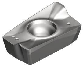
154 Fresatura / Milling Dimensioni (mm) Dimensions Gruppo materiali ISO / ISO material group Articolo Reference Rompitruciolo da 4 MP Chip breaker 4MP l d s r b PM KS N H Codice Code APKT 1003PDER-IT MP25BM-4MP APKT 1003PDER 11,35 - 3,770,8 2,5 • 71 170 977 APKT 1003PDER-IT MP40BM-4MP APKT 1003PDER 11,35 - 3,770,8 2,5 •• 67 064 127 APMT 1604PDER MP25BM-4MP APMT 1604PDER 17,32 - 5,170,8 1,54 • 71 170 985 APMT 1604PDER MP35BM-4MP APMT 1604PDER 17,32 5,170,8 1,54 • • 67 064 143 Inserti AP10…/AP16… Inserts AP10…/AP16… Applicazione principale / First choice Applicazione secondaria / Second choice Articolo Reference D d1 L l1 Ap max Irrigazione Internal coolant Z Ins. Insert N. taglienti Insert : nb of edges Codice Code MPFM90-AP10-D040-A16-Z05-H-4MP 40 16 40 - 9 O 5 AP 1003 2 65 253 003 MPFM90-AP10-D050-A22-Z06-H-4MP 50 22 40 - 9 O 6 AP 1003 2 65 253 011 MPFM90-AP10-D063-A22-Z07-H-4MP 63 22 40 - 9 O 7 AP 1003 2 65 253 038 MPFM90-AP16-D040-A16-Z04-H-4MP 40 16 40 - 15 O 4 AP 1604 2 65 253 046 MPFM90-AP16-D050-A22-Z05-H-4MP 50 22 40 - 15 O 5 AP 1604 2 65 253 054 MPFM90-AP16-D063-A22-Z06-H-4MP 63 22 40 - 15 O 6 AP 1604 2 65 253 062 MPFM90-AP16-D080-A27-Z07-H-4MP 80 27 50 - 15 O 7 AP 1604 2 65 253 070 MPFM90-AP16-D100-A32-Z08-H-4MP 100 32 50 - 15 O 8 AP 1604 2 65 253 089 Corpo fresa per spianatura 90° MPFM90-AP10-16 90° square shoulder milling cutter MPEM90-AP10-16 D L d1 apmax Inserti Inserts Vite Screw Chiave di serraggio Wrench Coppia di serraggio Torque Articolo Reference Codice Code Articolo Reference Codice Code AP-10 3008-M2.5x6-4MP 65 252 120 80-T08-4MP 65 252 171 1,0 Nm AP-16 4015-M4x9-4MP 65 252 163 80-T15-4MP 65 252 201 3,5 Nm Accessori Accessories Corpo fresa per spianatura 90° MPEM90-AP10-16 90° square shoulder milling cutter MPEM90-AP10-16 Articolo Reference D d1 L l1 Ap max Irrigazione Internal coolant Z Ins. Insert N. taglienti Insert : nb of edges Codice Code MPEM90-AP10-D16-W16-L100-Z02H-4MP 16 16 100 30 9 O 2 AP 1003 2 71 170 926 MPEM90-AP10-D20-W20-L100-Z03H-4MP 20 20 100 30 9 O 3 AP 1003 2 71 170 934 MPEM90-AP10-D25-W25-L100-Z04H-4MP 25 25 100 30 15 O 4 AP 1003 2 71 170 942 MPEM90-AP10-D32-W25-L105-Z05H-4MP 32 25 105 32 15 O 5 AP 1003 2 71 170 950 D D 1 L l1 apmax
Fresatura,
Avanzamento e profondità a seconda del materiale e del rompitruciolo
Advance and depth depending on material and chip breaker
155 Fresatura / Milling
parametri di taglio e�ettivi devono essere regolati in base a fattori quali la rigidità della macchina, il corpo dell’utensile, le condizioni del pezzo e il refrigerante.
chart for general cutting conditions. The actual selection should be adjusted according to factors such as machine rigidity, tool body, workpiece conditions and coolant. ISO Classificazione dei materiali Material classification AFNOR DIN Durezza Tensile strength (N / mm2) Durezza Hardness (HB) Profondità di taglio e avanzamento Cutting depth and feed AP10 - AP16 Ap (mm) fz (mm/dts) minmaxminmax P Acciaio non legato Non-alloyed steel / Low Alloyed S300 - 16NC6 9SMn36- 15CrNi6 < 600 < 180 0,210-15 0,1 0,2 XC18 - 16NC6 Ck15 - 15NiCr6 < 950 < 280 Acciaio legato Alloyed steel 42CD4 - XC60 42CrMo4 - Ck60 700 - 950 200 - 280 0,1 0,18 Z40CDV4 X40CrMoV5 950 - 1200 280 - 355 55NCDV7 - Z40C14 55NiCrMoV6 - X30Cr13 1200-1400 355-415 M Acciaio inossidabile Duplex stainless steel Z2CNDN22.05 X2CrNiMoN22-5 778 230 0,210-15 0,1 0,18 Acciaio inossidabile austenitico Austenitic stainless steel 304L - 316L - Z6CN18.09 304, 316, X6CrNi18-10 675 200 0,1 0,18 Acciaio inossidabile molto tenace e altamente legato Precipitation hardening stainless steel Z3CNDN25.07Az X2CrNiMoN25 7 4 1013 300 K Ghisa grigia Grey cast iron FT20D - FT40D GG20, GG40 700 220 - - -Ghisa lamellare Nodular cast iron FGS400-12 - FGS700-2 GGG40, GGG70 880 260 Ghisa malleabile Malleable cast iron P540/5 GTS 55 04 800 250 S Superleghe a base di ferro Fe-based alloy Discalloy 943 280 0,210-150,060,12 Superleghe a base di cobalto Co-based alloy Stellite 21 1076 320 Superleghe a base di nichel Ni-based alloy Inconel 718 1177 350 Lega di titanio Ti-alloy TiAl6V4 1262 370 N Alluminio < 9% Aluminum < 9% A-U4SG AlCuSiMn 260 75 0,210-150,120,15 0,210-150,1 0,15 Lega di alluminio Aluminum alloy A-S10G G-AlSi10Mg 447 130 H Acciaio cementato, per utensili, temprato, al manganese, ecc. Hardened steel 100C6 - Z40CDV5 Z120M12 100Cr6 - X40CrMoV5 1 X120Mn12 50-60HRC 50-60HRC -Ghisa bianca Chilled cast iron Grado 2B Grade 2B FB Ni4 Cr2HC 50-60HRC 55HRC
corpi fresa, inserti e condizioni d’uso Milling, toolholders, inserts and conditions of use 02 *I
*Above
02
Fresatura, corpi fresa, inserti e condizioni d’uso
Milling, toolholders, inserts and conditions of use
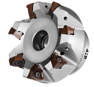

156 Fresatura / Milling Corpo fresa per spianatura 90° MPFM90-WN08 90° square shoulder milling cutter HPFM90-WN08 Articolo Reference D d1 L l1 Ap max Irrigazione Internal coolant Z Ins. Insert N. taglienti Insert : nb of edges Codice Code MPFM90-WN08-D50-A22-L40-Z04-AR-4MP 50 22 40 - 8 4 WN.U 0806 6 67 061 292 MPFM90-WN08-D63-A22-L40-Z06-AR-4MP 63 22 40 - 8 6 WN.U 0806 6 67 061 306 MPFM90-WN08-D80-A27-L50-Z07-AR-4MP 80 27 50 - 8 7 WN.U 0806 6 67 061 314 MPFM90-WN08-D100-A32-L50-Z08-AR-4MP 100 32 50 - 8 8 WN.U 0806 6 67 061 322 MPFM90-WN08-D125-A40-L61-Z11-AR-4MP 125 40 61 - 8 11 WN.U 0806 6 67 061 330 Dimensioni (mm) Dimensions (mm) Gruppo materiali ISO / Material group Articolo Reference Rompitruciolo da 4 MP Chip breaker 4MP l d s r P M K S N H Codice Code WNGU 080604R-LSP MP40BM-4MP WNGU 080604R-LSP 812,512,5 0,4 • • 67 063 813 WNGU 080604R-LSP MP35BM-4MP WNGU 080604R-LSP 812,512,5 0,4 • • 67 063 821 WNGU 080604R-GPM MP35BM-4MP WNGU 080604R-GPM 812,512,5 0,4 • • 67 063 848 WNGU 080604R-GPM MP40BM-4MP WNGU 080604R-GPM 812,512,5 0,4 • • 67 063 856 WNGU 080608R-GPM MC30BP-4MP WNGU 080608R-GPM 812,512,5 0,8 • 67 063 864 WNGU 080608R-GPM MP25BM-4MP WNGU 080608R-GPM 812,512,5 0,8 • 71 170 993 WNGU 080608R-MPK MC30BK-4MP WNGU 080608R-MPK 812,512,5 0,8 • 67 063 880 WNGU 080608R-MPK MP25BM-4MP WNGU 080608R-MPK 812,512,5 0,8 • 71 171 000 WNGU 080608R-LAA MN10AK-4MP WNGU 080608R-LAA 812,512,5 0,8 • 69 108 954 WNGU 080608R-GPH MP15BH-4MP WNGU 080608R-GPH 812,512,5 0,8 • 69 108 970 Inserti WN08… Inserts WN08… Vite Screw Chiave di serraggio Wrench Coppia di serraggio Torque 3,5 Nm Articolo Reference Codice Code Articolo Reference Codice Code MPSP040085H-4MP 67 064 232 MPDT-TP15-4MP 67 064 216 Accessori Accessories Applicazione principale / First choice Applicazione secondaria / Second choice
Fresatura, corpi fresa, inserti e condizioni d’uso Milling, toolholders, inserts and conditions of use
Avanzamento e profondità a seconda del materiale e del rompitruciolo
Advance and depth depending on material and chip breaker
di taglio e avanzamento
*I parametri devono essere adeguati in base a diversi fattori come la rigidità della macchina, la soluzione di bloccaggio, le condizioni di lavorazione e la soluzione di ra�reddamento.
*Recommendations should be adjusted according to several factors such as machine rigidity, clamping solution, machining conditions and coolant solution.
157 Fresatura / Milling
ISO Classificazione dei materiali Material classification AFNOR DIN Durezza Tensile strength (N / mm2) Durezza Hardness (HB) Profondità
Cutting depth and feed WNGU 08 Ap (mm) LAA LSP GPM / GPH MPK fz (mm/dts) min max minmaxmin max min max min max P Acciaio non legato Non-alloyed steel / Low Alloyed S300 - 16NC6 9SMn36- 15CrNi6 < 600 < 180 0,68 - -0,12 0,22 0,10,28 0,15 0,30 XC18 - 16NC6 Ck15 - 15NiCr6 < 950 < 280 0,10,26 Acciaio legato Alloyed steel 42CD4 - XC60 42CrMo4 - Ck60700 - 950 200 - 280 Z40CDV4 X40CrMoV5 950 - 1200 280 - 355 - -0,120,180,10,20 0,15 0,24 55NCDV7 - Z40C14 55NiCrMoV6X30Cr13 1200-1400355-415 0,15 0,20 M Acciaio inossidabile Duplex stainless steel Z2CNDN22.05 X2CrNiMoN22-5 778 230 -0,120,180,100,20- -0,12 0,16 0,100,18 0,170,32 Acciaio inossidabile austenitico Austenitic stainless steel 304L - 316LZ6CN18.09 304, 316, X6CrNi18-10 675 200 Acciaio inossidabile molto tenace e altamente legato Precipitation hardening stainless steel Z3CNDN25.07Az X2CrNiMoN25 7 4 1013 300 - -0,120,120,100,24K Ghisa grigia Grey cast iron FT20D - FT40D GG20, GG40 700 220 - -0,12 0,20 0,100,28 0,15 0,30 Ghisa lamellare Nodular cast iron FGS400-12 - FGS7002 GGG40, GGG70 880 260 Ghisa malleabile Malleable cast iron P540/5 GTS 55 04 800 250 - -0,120,180,100,24 0,15 0,26 S Superleghe a base di ferro Fe-based alloy Discalloy 943 280 - -0,120,130,100,15Superleghe a base di cobalto Co-based alloy Stellite 21 1076 320 - -0,120,120,100,13 Superleghe a base di nichel Ni-based alloy Inconel 718 1177 350 Lega di titanio Ti-alloy TiAl6V4 1262 370 - -0,120,130,100,15 N Aluminio < 9% Aluminum < 9% A-U4SG AlCuSiMn 260 75 0,10 0,24 - -Lega di alluminio Aluminum alloy A-S10G G-AlSi10Mg 447 130 0,100,24 H Acciaio cementato, per utensili, temprato, al manganese, ecc. Hardened steel 100C6 - Z40CDV5 Z120M12 100Cr6 - X40CrMoV5 1 X120Mn125060HRC - - - 0,10,15Ghisa bianca Chilled cast iron Grado 2B Grade 2B FB Ni4 Cr2HC - 55HRC
02
Fresatura, corpi fresa, inserti e condizioni d’uso Milling, toolholders, inserts and conditions of use 02
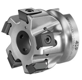
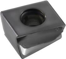
158 Fresatura / Milling Articolo Reference D d1 L l1 Ap max Refrigerazione Internal coolant Z Ins. Insert N. taglienti Insert : nb of edges Code Code MPFM90-LN13-D40-A16-L40-Z04-AR-4MP 40 16 40 - 12 4 LNHU 1306 4 67 061 357 MPFM90-LN13-D50-A22-L40-Z05-AR-4MP 50 22 40 - 12 5 LNHU 1306 4 67 061 365 MPFM90-LN13-D63-A22-L40-Z06-AR-4MP 63 22 40 - 12 6 LNHU 1306 4 67 061 373 MPFM90-LN13-D63-A22-L40-Z08-AR-4MP 63 22 40 - 12 8 LNHU 1306 4 67 061 381 MPFM90-LN13-D80-A27-L50-Z07-AR-4MP 80 27 50 - 12 7 LNHU 1306 4 67 061 411 MPFM90-LN13-D80-A27-L50-Z10-AR-4MP 80 27 50 - 12 10 LNHU 1306 4 67 061 438 MPFM90-LN13-D100-A32-L50-Z09-AR-4MP 100 32 50 - 12 9 LNHU 1306 4 67 061 446 MPFM90-LN13-D100-A32-L50-Z13-AR-4MP 100 32 50 - 12 13 LNHU 1306 4 67 061 454 Corpo fresa per spianatura 90° MPFM90-LN13 90° square shoulder milling cutter MPFM90-LN13 Vite Screw Chiave di serraggio Wrench Coppia di serraggio Torque 3,5 Nm Articolo Reference Codice Code Articolo Reference Codice Code MPSP040112-4MP 67 064 259 MPDT-TP15-4MP 67 064 216 Accessori Accessories Dimensioni (mm) Dimensions (mm) Gruppo materiali ISO / ISO material group Articolo Reference Rompitruciolo da 4 MP Chip breaker 4MP l d s r b P M K S N H Codice Code LNHU 130608ER-MPK MP25BM-4MP LNHU 130608ER-MPK 13,26,810,150,8 2,7 • 71 171 019 LNHU 130608ER-MPK MP35BM-4MP LNHU 130608ER-MPK 13,26,810,150,8 2,7 • • 67 063 910 LNHU 130608ER-MPK MP40BM-4MP LNHU 130608ER-MPK 13,26,810,150,8 2,7 • • 67 063 929 LNHU 130608ER-MPK MC30BK-4MP LNHU 130608ER-MPK 13,26,810,150,8 2,7 • 67 063 937 LNHU 130608ER-LAA MN10AK-4MP LNHU 130608ER-LAA 13,26,810,150,8 2,7 • 69 108 962 Inserti LN13... Inserts LN13… b Applicazione principale / First choice Applicazione secondaria / Second choice
Avanzamento e profondità a seconda del materiale e del rompitruciolo
Advance and depth depending on material and chip breaker
*I parametri devono essere adeguati in base a diversi fattori come la rigidità della macchina, la soluzione di bloccaggio, le condizioni di lavorazione e la soluzione di ra�reddamento.
*Recommendations should be adjusted according to several factors such as machine rigidity, clamping solution, machining conditions and coolant solution.
159 Fresatura / Milling
toolholders, inserts and
02 ISO Classificazione dei materiali Material classification AFNOR DIN Durezza Tensile strength (N / mm2) Durezza Hardness (HB) Profondità di taglio e avanzamento Cutting depth and feed LNHU1306 MPK LAA Ap (mm) fz (mm/dts) mm minmaxminmaxminmax P Acciaio non legato Non-alloyed steel / Low Alloyed S300 - 16NC6 9SMn36- 15CrNi6 < 600 < 180 0,6 12 0,120,24 -XC18 - 16NC6 Ck15 - 15NiCr6 < 950 < 280 0,120,18 Acciaio legato Alloyed steel 42CD4 - XC60 42CrMo4 - Ck60 700 - 950 200 - 280 0,120,18 Z40CDV4 X40CrMoV5 950 - 1200 280 - 355 0,120,14 55NCDV7 - Z40C14 55NiCrMoV6 - X30Cr131200-1400355-415 0,120,14 M Acciaio inossidabile Duplex stainless steel Z2CNDN22.05 X2CrNiMoN22-5 778 230 0,120,16 Acciaio inossidabile austenitico Austenitic stainless steel 304L - 316L - Z6CN18.09304, 316, X6CrNi18-10 675 200 0,120,15 Acciaio inossidabile molto tenace e altamente legato Precipitation hardening stainless steel Z3CNDN25.07Az X2CrNiMoN25 7 4 1013 300 0,120,14 K Ghisa grigia Grey cast iron FT20D - FT40D GG20, GG40 700 220 0,120,3 Ghisa lamellaree Nodular cast iron FGS400-12 - FGS700-2 GGG40, GGG70 880 260 0,120,24 Ghisa malleabile Malleable cast iron P540/5 GTS 55 04 800 250 0,120,18 S Superleghe a base di ferro Fe-based alloy Discalloy 943 280 0,120,14 Superleghe a base di cobalto Co-based alloy Stellite 21 1076 320 0,120,14 Superleghe a base di nichel Ni-based alloy Inconel 718 1177 350 0,120,14 Lega di titanio Ti-alloy TiAl6V4 1262 370 0,120,14 N Alluminio < 9% Aluminum < 9% A-U4SG AlCuSiMn 260 75 - 0,08 0,30 Lega di alluminio Aluminum alloy A-S10G G-AlSi10Mg 447 130 H Acciaio per utensili temprato al manganese Hardened steel 100C6 - Z40CDV5Z120M12 100Cr6-X40CrMov5-1 X120Mn12 50-60HRC50-60HRCGhisa bianca Chilled cast iron Grado 2B Grade 2B FBNi4 Cr2HC 55HRC 55HRC
Fresatura, corpi fresa, inserti e condizioni d’uso Milling,
conditions of use
Fresatura, corpi fresa, inserti e condizioni d’uso Milling, toolholders, inserts and conditions of use 02
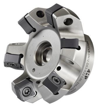
Corpo fresa per spianatura a 45° MPFF45-SN12
45° Approach angle milling cutter for face milling MPFF45-SN12
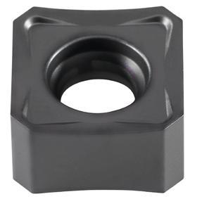
160 Fresatura / Milling Articolo Reference D d1 L l1 Apmax Refrigerazione Internal coolant Z Ins. Insert N. taglienti Insert : nb of edges Codice Code MPFF45-SN12-D50-A22-L40-Z04-AR-N-4MP 50 22 40 - 6,5 4 SN.X 1206 8 67 061 462 MPFF45-SN12-D63-A22-L40-Z06-AR-N-4MP 63 22 40 - 6,5 6 SN.X 1206 8 67 061 470 MPFF45-SN12-D80-A27-L50-Z05-AR-N-4MP 80 27 50 - 6,5 5 SN.X 1206 8 67 061 489 MPFF45-SN12-D80-A27-L50-Z07-AR-N-4MP 80 27 50 - 6,5 7 SN.X 1206 8 68 118 069 MPFF45-SN12-D100-A32-L50-Z06-AR-N-4MP 100 32 50 - 6,5 6 SN.X 1206 8 67 061 497 MPFF45-SN12-D100-A32-L50-Z08-AR-N-4MP 100 32 50 - 6,5 8 SN.X 1206 8 68 118 077 MPFF45-SN12-D125-A40-L63-Z08-AR-N-4MP 125 40 63 - 6,5 8 SN.X 1206 8 67 061 500 MPFF45-SN12-D160-A40-L63-Z10-NR-N-4MP 160 40 63 - 6,5 - 10 SN.X 1206 8 67 061 519
Dimensioni (mm) Dimensions (mm) Gruppo materiali ISO ISO material group Articolo Reference Rompitruciolo da 4 MP Chip breaker 4MP lds rb PM KS N H Codice Code SNHX 1206ZNN-AAA MN10AA-4MP SNHX 1206ZNN-AAA 12,7-6,98- 1,8 • 67 063 945 SNGX 1206ANN-GPM MP35BM-4MP SNGX 1206ANN-GPM 12,7-6,98- 1,8 • • 67 063 953 SNGX 1206ANN-GPM MP25BM-4MP SNGX 1206ANN-GPM 12,7-6,98- 1,8 • 71 171 027 SNGX 1206ANN-RPK MP25BK-4MP SNGX 1206ANN-RPK 12,7-6,98- 1,8 • 71 171 035 SNGX 1206ANN-RPK MP25BM-4MP SNGX 1206ANN-RPK 12,7-6,98- 1,8 • 71 171 043 SNGX 1206ANN-RKK MC30BK-4MP SNGX 1206ANN-RKK 12,7-6,98- 1,8 • 67 064 003 Inserti SN12… Inserts SN12… Vite Screw Chiave di serraggio Wrench Coppia di serraggio Torque 5,0 Nm Articolo Reference Codice Code Articolo Reference Codice Code MPSP050120-4MP 67 292 014 MPDT-TP20-4MP 67 416 805 Accessori Accessories Applicazione principale / First choice Applicazione secondaria / Second choice
Fresatura, corpi fresa, inserti e condizioni d’uso Milling,
Avanzamento e profondità a seconda del materiale e del rompitruciolo
Advance and depth depending on material and chip breaker
Profondità di taglio e avanzamento / Cutting depth and feed
*I parametri devono essere adeguati in base a diversi fattori come la rigidità della macchina, la soluzione di bloccaggio, le condizioni di lavorazione e la soluzione di ra�reddamento.
*Recommendations should be adjusted according to several factors such as machine rigidity, clamping solution, machining conditions and coolant solution.
161 Fresatura / Milling
02 ISO Classificazione dei materiali Material classification AFNOR DIN Durezza Tensile strength (N / mm2) Durezza Hardness (HB)
SNHX/SNGX 1206.. Ap (mm) GPM RPK RKK AAA fz (mm/dts) fz (mm/dts)fz (mm/dts)fz (mm/dts) minmaxminmaxminmaxminmaxminmax P Acciaio non legato Non-alloyed steel Low Alloyed S300 - 16NC6 9SMn36 15CrNi6 < 600 < 180 0,66-7 0,180,45 - 0,203,00XC18 - 16NC6 Ck15 15NiCr6 < 950 < 280 0,220,500,270,55Acciaio legato Alloyed steel 42CD4 - XC60 42CrMo4 Ck60, 700 - 950 200 - 280 0,150,400,200,450,250,50Z40CDV4 X40CrMoV5 950 - 1200 280 - 355 0,150,350,180,400,220,4555NCDV7 Z40C14 55NiCrMoV6 X30Cr13 1200-1400355-415 0,120,250,150,300,180,35M Acciaio inossidabile Duplex stainless steel Z2CNDN22.05 X2CrNiMo N22-5 778 230 0,220,35 - -Acciaio inossidabile austenitico Austenitic stainless steel 304L - 316L Z6CN18.09 304, 316 X6CrNi18-10 675 200 0,180,350,200,400,240,45Acciaio inossidabile molto tenace e altamente legato Precipitation hardening stainless steel Z3CNDN25.07Az X2CrNiMo N25 7 4 1013 300 0,150,30 - -K Ghisa grigia Grey cast iron FT20D - FT40D GG20 GG40 700 220 0,180,500,220,600,260,70Ghisa lamellare Nodular cast iron FGS400-12 FGS700-2 GGG40 GGG70 880 260 0,180,1450,220,500,260,60Ghisa malleabile Malleable cast iron P540/5 GTS 55 04 800 250 0,220,500,260,600,300,60S Superleghe a base di ferro Fe-based alloy Discalloy 943 280 0,120,300,150,350,180,35Superleghe a base di cobalto Co-based alloy Stellite 21 1076 320 0,040,130,040,15 -Superleghe a base di nichel Ni-based alloy Inconel 718 1177 350 0,070,200,120,22 -Lega di titanio Ti-alloy TiAl6V4 1262 370 0,100,25 -N Alluminio < 9% Aluminum < 9% A-U4SG AlCuSiMn 260 75 - - - 0,100,30 Lega di alluminio Aluminum alloy A-S10G G-AlSi10Mg 447 130 - - - 0,100,24 H Acciaio per utensili temprato al manganese Hardened steel 100C6 - Z40CDV5 Z120M12 100Cr6-X40Cr Mov5 1X120Mn12 50-60HRC50-60HRC 0,100,200,120,250,150,30Ghisa bianca Chilled cast iron Grado 2B Grade 2B FBNi4 Cr2HC 55HRC 55HRC
toolholders, inserts and conditions of use
02
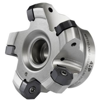
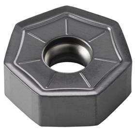
Fresatura, corpi fresa, inserti e condizioni d’uso Milling, toolholders, inserts and conditions of use
162 Fresatura / Milling Vite Screw Chiave di serraggio Wrench Coppia di serraggio Torque 3,5 Nm Articolo Reference Codice Code Articolo Reference Codice Code MPSP040112-4MP 67 064 259 MPDT-TP15-4MP 67 064 216 Accessori Accessories Articolo Reference D d1 L l1Apmax Refrigerazione Internal coolant Z Ins. Insert N. taglienti Insert : nb of edges Codice Code MPFF45-XN07-D40-A16-L40-Z03-AR-4MP 40 16 40 - 4,4 3 XN.U 0705 14 67 061 535 MPFF45-XN07-D50-A22-L40-Z04-AR-4MP 50 22 40 - 4,4 4 XN.U 0705 14 67 061 543 MPFF45-XN07-D63-A22-L40-Z05-AR-4MP 63 22 40 - 4,4 5 XN.U 0705 14 67 061 551 MPFF45-XN07-D80-A27-L50-Z06-AR-4MP 80 27 50 - 4,4 6 XN.U 0705 14 67 061 578 MPFF45-XN07-D100-A32-L50-Z07-AR-4MP 100 32 50 - 4,4 7 XN.U 0705 14 67 061 586 MPFF45-XN07-D125-A40-L63-Z08-AR-4MP 125 40 63 - 4,4 8 XN.U 0705 14 67 061 594 MPFF45-XN07-D160-A40-L63-Z09-NR-4MP 160 40 63 - 4,4 - 9 XN.U 0705 14 67 061 608 Corpo fresa per spianatura a 45° MPFF45-XN07 45° Approach angle milling cutter for face milling MPFF45-XN07 45° Dimensioni (mm) Dimensions (mm) Gruppo materiali ISO ISO material group Articolo Reference Rompitruciolo da 4 MP Chip breaker 4MP l d s r b P M K S N H Codice Code XNMU 0705ANN-GPM MP25BM-4MP XNMU 0705ANN-GPM 714,55,40,8 1,1 • 71 171 051 XNMU 0705ANN-GPM MP35BM-4MP XNMU 0705ANN-GPM 714,55,40,8 1,1 • • 67 064 038 XNGX 0705ANN-W MP30BM-4MP XNGX 0705ANN-W (wiper)- 155,41 6 • 67 064 046 Inserti XN07.../XN07...W(wiper) Inserts XN07.../XN07...W(wiper)
Applicazione principale / First choice Applicazione secondaria / Second choice
XNGX..07 XNMU..07
Fresatura, corpi fresa, inserti e condizioni d’uso
Milling, toolholders, inserts and conditions of use 02
Avanzamento e profondità a seconda del materiale e del rompitruciolo
Advance and depth depending on material and chip breaker
Profondità di taglio e avanzamento
*I parametri devono essere adeguati in base a diversi fattori come la rigidità della macchina, la soluzione di bloccaggio, le condizioni di lavorazione e la soluzione di ra�reddamento.
*Recommendations should be adjusted according to several factors such as machine rigidity, clamping solution, machining conditions and coolant solution.
163 Fresatura / Milling
ISO Classificazione dei materiali Material classification AFNOR DIN Durezza Tensile strength (N / mm2) Durezza Hardness (HB)
Cutting depth and feed XN… 0705… Ap (mm) GPM fz (mm/dts) min max min max P Acciaio non legato Non-alloyed steel Low Alloyed S300 - 16NC6 9SMn36 15CrNi6 < 600 < 180 0,60 3,6-4,4 0,18 0,45 XC18 - 16NC6 Ck15 15NiCr6 < 950 < 280 Acciaio legato Alloyed steel 42CD4 - XC60 42CrMo4 Ck60, 700 - 950 200 - 280 0,15 0,40 Z40CDV4 X40CrMoV5 950 - 1200 280 - 355 0,15 0,35 55NCDV7 Z40C14 55NiCrMoV6 X30Cr13 1200-1400355-415 0,12 0,25 M Acciaio inossidabile Duplex stainless steel Z2CNDN22.05 X2CrNiMo N22-5 778 230 0,20 0,35 Acciaio inossidabile austenitico Austenitic stainless steel 304L - 316L Z6CN18.09 304, 316 X6CrNi18-10 675 200 0,18 0,35 Acciaio inossidabile molto tenace e altamente legato Precipitation hardening stainless steel Z3CNDN25.07Az X2CrNiMo N25 7 4 1013 300 0,15 0,30 K Ghisa grigia Grey cast iron FT20D - FT40D GG20 GG40 700 220 0,18 0,45 Ghisa lamellare Nodular cast iron FGS400-12 FGS700-2 GGG40 GGG70 880 260 0,18 0,45 Ghisa malleabile Malleable cast iron P540/5 GTS 55 04 800 250 0,20 0,40 S Superleghe a base di ferro Fe-based alloy Discalloy 943 280 0,12 0,25 Superleghe a base di cobalto Co-based alloy Stellite 21 1076 320 0,04 0,13 Superleghe a base di nichel Ni-based alloy Inconel 718 1177 350 0,07 0,20 Lega di titanio Ti-alloy TiAl6V4 1262 370 0,10 0,25 N Alluminio < 9% Aluminum < 9% A-U4SG AlCuSiMn 260 75Lega di alluminio Aluminum alloy A-S10G G-AlSi10Mg 447 130 H Acciaio per utensili temprato al manganese Hardened steel 100C6 - Z40CDV5 Z120M12 100Cr6 - X40CrMoV5 1 -X120Mn12 50-60HRC50-60HRCGhisa bianca Chilled cast iron Grado 2B Grade 2B FBNi4 Cr2HC 55HRC 55HRC
02
Fresatura, corpi fresa, inserti e condizioni d’uso
Milling, toolholders, inserts and conditions of use
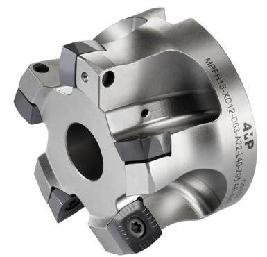
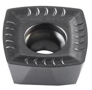
164 Fresatura / Milling Corpo fresa ad alto avanzamento 15° MPFH15-XD12 15° Approach angle milling cutter for high feed MPFH15-XD12 Articolo Reference D d1 L Apmax Refrigerazione Internal coolant Z Ins. Insert N. taglienti Insert : nb of edges Codice Code MPFH15-XD12-D52-A27-L40-Z05-AR-4MP 52 27 40 2,5 5 XD..1205 4 71 171 086 MPFH15-XD12-D63-A22-L40-Z05-AR-4MP 63 22 40 2,5 5 XD..1205 4 67 061 675 MPFH15-XD12-D80-A27-L50-Z08-AR-4MP 80 27 50 2,5 8 XD..1205 4 71 171 094 MPFH15-XD12-D100-A32-L50-Z09-AR-4MP 10032 50 2,5 9 XD..1205 4 71 171 108 Vite Screw Chiave di serraggio Wrench Coppia di serraggio Torque 3,5 Nm Articolo Reference Codice Code Articolo Reference Codice Code MPSP040112-4MP 67 064 259 MPDT-TP15-4MP 67 064 216 Accessori Accessories Inserti XD…1205 Inserts XD…1205 Dimensioni (mm) Dimensions (mm) Gruppo materiali ISO ISO material group Articolo Reference Rompitruciolo da 4 MP Chip breaker 4MP l d s r b P M K S N H Codice Code XDLT 120508ER-LSP MP25BM-4MP XDLT 120508ER-LSP -12,75,560,8 2,2 • 71 171 116 XDLT 120508ER-LSP MP35BM-4MP XDLT 120508ER-LSP -12,75,560,8 2,2 • • 67 064 100 XDMW 120508ER-RKK MC30BK-4MP XDMW 120508ER-RKK -12,75,560,8 2,2 • 67 064 119 Applicazione principale / First choice Applicazione secondaria / Second choice
Fresatura, corpi fresa, inserti e condizioni d’uso
Milling, toolholders, inserts and conditions of use 02
Avanzamento e profondità a seconda del materiale e del rompitruciolo
Advance and depth depending on material and chip breaker
Profondità di taglio e avanzamento / Cutting depth and feed
XD..1205.. Fresatura di spallamento
*I parametri devono essere adeguati in base a diversi fattori come la rigidità della macchina, la soluzione di bloccaggio, le condizioni di lavorazione e la soluzione di ra�reddamento.
*Recommendations should be adjusted according to several factors such as machine rigidity, clamping solution, machining conditions and coolant solution.
165 Fresatura / Milling
ISO Classificazione dei materiali Material classification AFNOR DIN Durezza Tensile strength (N / mm2) Durezza Hardness (HB)
Shoulder Milling Tu�o Plunging Ap (mm) fz (mm/dts) Ap (mm) fz (mm/dts) min max min max min max min max P Acciaio non legato Non-alloyed steel Low Alloyed S300 - 16NC6 9SMn36 15CrNi6 < 600 < 180 0,50 2,5 0,30 2,00 0,50 9 0,10 0,25 XC18 - 16NC6 Ck15 15NiCr6 < 950 < 280 Acciaio legato Alloyed steel 42CD4 - XC60 42CrMo4 Ck60, 700 - 950 200 - 280 0,30 2,00 0,10 0,18 Z40CDV4 X40CrMoV5 950 - 1200 280 - 355 55NCDV7 Z40C14 55NiCrMoV6 X30Cr13 1200-1400355-415 M Acciaio inossidabile Duplex stainless steel Z2CNDN22.05 X2CrNiMo N22-5 778 230 0,20 1,00 0,12 0,18 Acciaio inossidabile austenitico Austenitic stainless steel 304L - 316L Z6CN18.09 304, 316 X6CrNi18-10 675 200 Acciaio inossidabile molto tenace e altamente legato Precipitation hardening stainless steel Z3CNDN25.07Az X2CrNiMo N25 7 4 1013 300 0,10 0,60 0,05 0,10 K Ghisa grigia Grey cast iron FT20D - FT40D GG20 GG40 700 220 0,30 2,00 0,30 2,00 Ghisa lamellare Nodular cast iron FGS400-12 FGS700-2 GGG40 GGG70 880 260 Ghisa malleabile Malleable cast iron P540/5 GTS 55 04 800 250 S Superleghe a base di ferro Fe-based alloy Discalloy 943 280 0,30 2,00 0,10 0,25 Superleghe a base di cobalto Co-based alloy Stellite 21 1076 320 Superleghe a base di nichel Ni-based alloy Inconel 718 1177 350 Lega di titanio Ti-alloy TiAl6V4 1262 370 N Alluminio < 9% Aluminum < 9% A-U4SG AlCuSiMn 260 75 0,30 1,50 0,10 0,40 Lega di alluminio Aluminum alloy A-S10G G-AlSi10Mg 447 130 H Acciaio per utensili temprato al manganese Hardened steel 100C6 - Z40CDV5 Z120M12 100Cr6-X40Cr Mov5 1X120Mn12 50-60HRC50-60HRC 0,30 1,00 0,08 0,15 Ghisa bianca Chilled cast iron Grado 2B Grade 2B FBNi4 Cr2HC 55HRC 55HRC
02
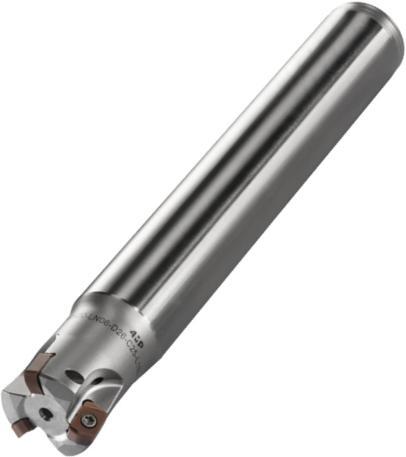
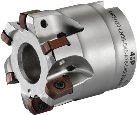
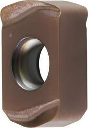
Fresatura, corpi fresa, inserti e condizioni d’uso
Milling, toolholders, inserts and conditions of use
166 Fresatura / Milling Articolo Reference D d1 L l1 Ap max Refrigerazione Internal coolant Z Ins. Insert N. taglienti Insert : nb of edges Codice Code MPFH20-LN06-D40-A16-L40-Z06-AR-4MP 40 16 40 - 0,7 6 LNMX 0604 4 67 061 659 Corpo fresa ad alto avanzamento MPFH20-LN06...A Milling cutter for high speed MPFH20-LN06...A Vite Screw Chiave di serraggio Wrench Coppia di serraggio Torque 1,0 Nm Articolo Reference Codice Code Articolo Reference Codice Code MPSP02506450H-4MP 67 064 224 MPDT-TP08-4MP 67 064 208 Accessori Accessories Dimensioni (mm) Dimensions (mm) Gruppo materiali ISO / Material group Articolo Reference Rompitruciolo da 4 MP Chip breaker 4MP l d s r b P M K S N H Codice Code LNMX 060410R-LSP MP35BM-4MP LNMX 060410R-LSP 106,353,61,0 - • • 67 064 054 LNMX 060410R-LSP MP40BM-4MP LNMX 060410R-LSP 106,353,61,0 - • 67 064 062 LNMX 060410R-GPM MP25BM-4MP LNMX 060410R-GPM 106,353,61,0 - • 71 171 078 LNMX 060410R-GPM MP35BM-4MP LNMX 060410R-GPM 106,353,61,0 - • • 67 064 089 LNMX 060410R-GPH MP15BH-4MP LNMX 060410R-GPH 106,353,61,0 - • 69 108 989 Inserti LN06… Inserts LN06… Articolo Reference D d1 L l1 Ap max Refrigerazione Internal coolant Z Ins. Insert N. taglienti Insert : nb of edges Codice Code MPEH20-LN06-D17-C16-L150-Z02-AR-4MP 17 16 150 25 0,7 2 LNMX 0604 4 67 061 616 MPEH20-LN06-D21-C20-L160-Z03-AR-4MP 21 2016030 0,7 3 LNMX 0604 4 67 061 624 MPEH20-LN06-D26-C25-L180-Z03-AR-4MP 26 25 180 35 0,7 3 LNMX 0604 4 67 061 632 MPEH20-LN06-D33-C32-L200-Z04-AR-4MP 33 3220035 0,7 4 LNMX 0604 4 67 061 640
alto avanzamento MPEH20-LN06...C
speed MPEH20-LN06...C D d1 l1 L Applicazione principale / First choice Applicazione secondaria / Second choice
Corpo fresa ad
Milling cutter for high
Fresatura, corpi fresa, inserti e condizioni d’uso Milling, toolholders, inserts and conditions of use
Avanzamento e profondità a seconda del materiale e del rompitruciolo
Advance and depth depending on material and chip breaker
di taglio e avanzamento / Cutting depth and feed
I parametri devono essere adeguati in base a diversi fattori come la rigidità della macchina, la soluzione di bloccaggio, le condizioni di lavorazione e la soluzione di ra�reddamento.
Recommendations should be adjusted according to several factors such as machine rigidity, clamping solution, machining conditions and coolant solution.
**Esclusivamente per il grado MP15BH
**Only with grade MP15BH
167 Fresatura / Milling
ISO Classificazione dei materiali Material classification AFNOR DIN Durezza Tensile strength (N / mm2) Durezza Hardness (HB)
LNMX 06.. Ap (mm) LSP GPM / GPH fz (mm/dts) fz (mm/dts) min max min max min max P Acciaio non legato Non-alloyed steel Low Alloyed S300 - 16NC6 9SMn36 15CrNi6 < 600 < 180 0,10 0,7 0,30 2,00 0,30 2,00 XC18 - 16NC6 Ck15 15NiCr6 < 950 < 280 Acciaio legato Alloyed steel 42CD4 - XC60 42CrMo4 Ck60, 700 - 950 200 - 280 Z40CDV4 X40CrMoV5 950 - 1200 280 - 355 55NCDV7 Z40C14 55NiCrMoV6 X30Cr13 1200-1400355-415 M Acciaio inossidabile Duplex stainless steel Z2CNDN22.05 X2CrNiMo N22-5 778 230 0,30 2,00 0,30 2,00 Acciaio inossidabile austenitico Austenitic stainless steel 304L - 316L Z6CN18.09 304, 316 X6CrNi18-10 675 200 Acciaio inossidabile molto tenace e altamente legato Precipitation hardening stainless steel Z3CNDN25.07Az X2CrNiMo N25 7 4 1013 300 K Ghisa grigia Grey cast iron FT20D - FT40D GG20 GG40 700 220 - - - - -Ghisa lamellare Nodular cast iron FGS400-12 FGS700-2 GGG40 GGG70 880 260 - - - - -Ghisa malleabile Malleable cast iron P540/5 GTS 55 04 800 250 - - - - -S Superleghe a base di ferro Fe-based alloy Discalloy 943 280 - - - - -Superleghe a base di cobalto Co-based alloy Stellite 21 1076 320 - - - - -Superleghe a base di nichel Ni-based alloy Inconel 718 1177 350 - - - - -Lega di titanio Ti-alloy TiAl6V4 1262 370 - - - - -N Alluminio < 9% Aluminum < 9% A-U4SG AlCuSiMn 260 75 - - - - -Lega di alluminio Aluminum alloy A-S10G G-AlSi10Mg 447 130 - - - - -H Acier cémenté à outils trempés au manganèse Hardened steel 100C6 - Z40CDV5 Z120M12 100Cr6-X40Cr Mov5 1X120Mn12 50-60HRC50-60HRC - - - - 0,3** 1,0** Fonte blanche Chilled cast iron Grado 2B Grade 2B FBNi4 Cr2HC 55HRC 55HRC - - - - - -
02
Profondità
INFORMAZIONI TECNICHE
MPEH /MPFH20
TECHNICAL INFORMATION MPEH / MPFH20
Fresatura in rampa Straight ramping
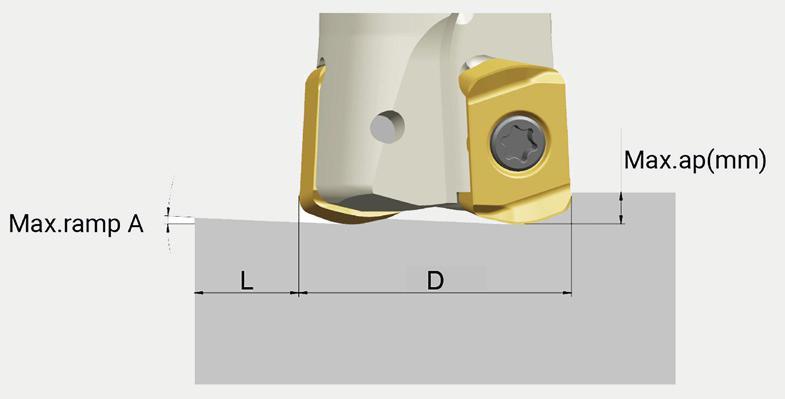
Fresatura in rampa
Diametro di taglio (D)
Fresatura per interpolazione elicoidale Helical ramping
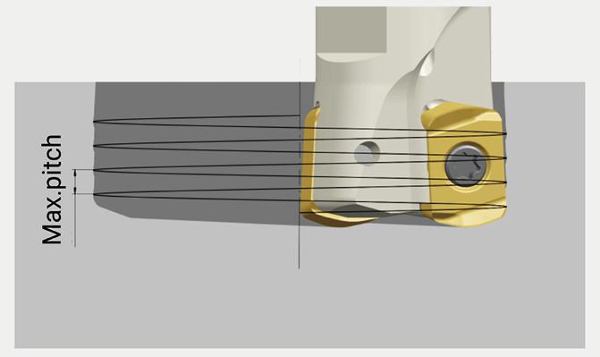
elicoidale
Raggio di programmazione NC Program Radius
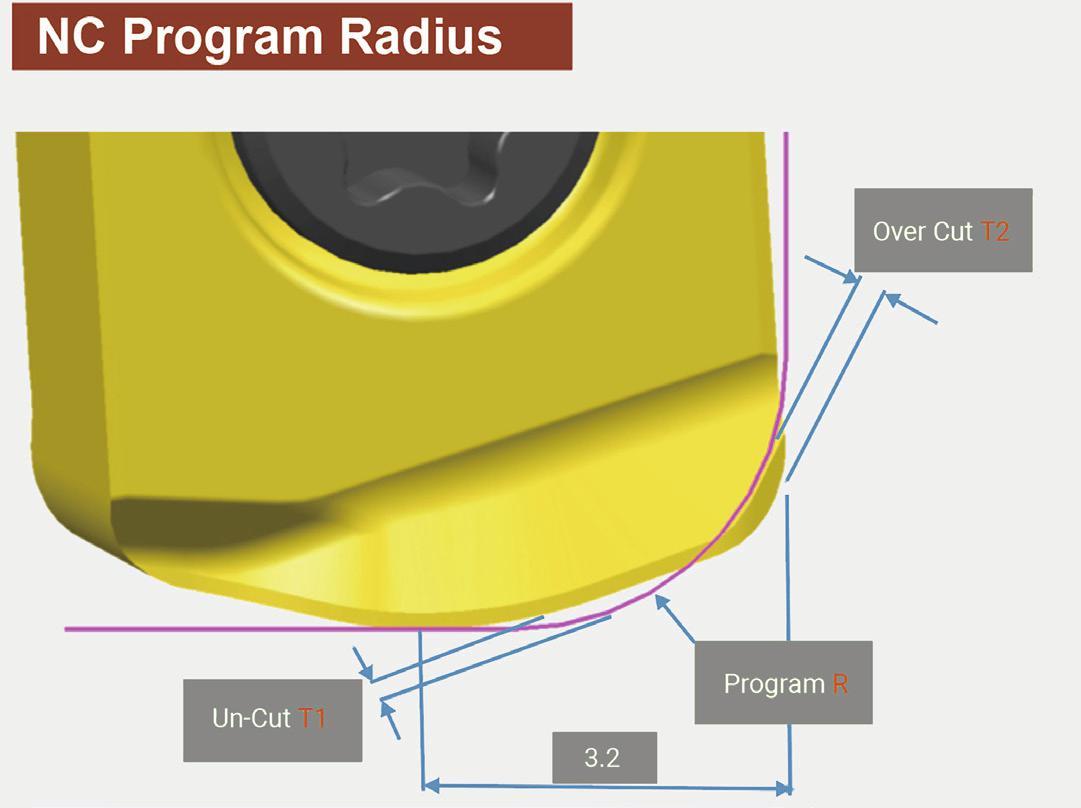
Dati per la programmazione NC
Technical information for NC program
Raggio di programmazione R
Nota: Selezionare il raggio di programmazione R1.5 per maggiorazione OCT2 = 0
Note : Select R1,5 as program R, without over-cut
168 Fresatura / Milling
Cutter diameter
Straight
Helical
Massimo Angolo di rampa-A Max. ramp-A Massimo. ap (mm) Max. ap (mm) Lunghezza minima L (mm) Min. length L (mm) min. diametro (mm) Min. dia. (mm) max. diametro (mm) Max. dia. (mm) Passo massimo (mm) Max. pitch (mm) Ø17 2,6° 0,7 15,4 25 34 0,7 Ø21 1,8° 0,7 22,3 33 42 0,7 Ø26 1,3° 0,7 30,8 43 52 0,7 Ø33 0,9° 0,7 44,6 57 66 0,7 Ø40 0,7° 0,7 57,3 71 80 0,7
ramp down Interpolazione
ramping
Program R Materiale rimanente T1 Un-Cut T1 Maggiorazione T2 Over-Cut T2 R1,5 0,43 0 R2,0 0,29 0,06 R2,5 0,15 0,24
Un-Cut T1 Program R Over-Cut T2 3.2
Massimo Angolo di rampa-A
Massimo. ap (mm)
Passo massimo
FRESATURA MILLING
Veloc�tà d� tagl�o e rotaz�one
Cutt�ng speed
1000 * Vc
n = (tr/m�n)
* Dc
* Dc * n Vc = (m/m�n)
1000
Vc: Veloc�tà d� tagl�o / Cutt�ng speed (m/m�n)
: 5 3.14
Dc: D�ametro / D�ameter (mm)
n: Veloc�tà d� rotaz�one / Sp�ndle speed (tr/m�n)
Avanzamento per dente
Feed rate per tooth
Vf
fz = (mm/z)
n * Z
fz: Avanzamento per dente / Feed rate per tooth (mm/z)
Vf: Avanzamento / Feed speed (mm/m�n)
n: Veloc�tà d� rotaz�one / Sp�ndle speed (tr/m�n)
Z: Numero d� dent� / Number of teeth
Avanzamento per g�ro
Feed rate per rev.
Vf
f = (mm/tr)
n
F: Avanzamento per g�ro / Feed rate per rev. (mm/tr)
Vf: Avanzamento / Feed speed (mm/m�n)
n: Veloc�tà d� rotaz�one / Sp�ndle speed (tr/m�n)
Technical information
Tempo d� lavoraz�one
Mach�n�ng t�me
L Tc = (m�n)
Vf
Tc: Tempo d� lavoraz�one / Mach�n�ng t�me (m�n)
L: Percorso d� lavoraz�one / Cutt�ng length (mm)
Vf: Avanzamento / Feed speed (mm/m�n)
Volume truc�olo Ch�p removal
ap * ae * Vf
Q = (cm3/m�n)
1000
Q: Volume truc�olo / Ch�p removal (cm�/m�n)
ap: Profond�tà d� tagl�o / Cutt�ng depth
ae: Innesto della fresa / Cutt�ng w�dth
Vf: Avanzamento / Feed speed (mm/m�n)
169
Informazioni tecniche
f ap
n
Fresatura / Milling
TABELLA DELLE EQUIVALENZE DEI GRADI DI FRESATURA MILLING GRADE CONVERSION TABLE
170 Fresatura / Milling Classificazione ISO Class�f�cat�on ISO 4MP COROMANT ISCAR KENNAMETAL JONGENKYOCERA MITSUBISHI SECOSUMITOMOINGERSOLLTUNGALOYWALTER P MP25BM MC30BP GC4220IC950 KC522M KC635M HT35 PR630 PR660 PR730 MC7020 MP1501 MP2501 ACP200IN2040 T3225 AH330 WKP25 MP35BM GC1130 GC4330 IC808 IC908 KC522M KC635M KC730M HC45 HT45 PR9925 PR830 FH7020 MP3000 MS2500 ACP300 IN6520 IN6530 AH120 AH725 AH730 GH330 WKP35 WKP35S M MP25BM GC1130 GC2030 GC1025 IC808 IC908 KC635MHT30 PR730 PR830 PR925 PR1025 FH7020 MP2501 F30M ACP200IN2040 T3130 AH725 AH120 WSM35 WXM35 MP35BM GC2040 S40T IC830 IC330 IC928 KC7725MHT32 PR1225 PR905 VP30RT F7030 F40M P2050 ACP300 IN6520 IN6530 AH130 AH140 SH730 WXM35 WSM35 WSP45 MP40BM GC4340 IC830 IC330 IC928 KC725M KC935M HT50 F7030 MM4500 MP2050 ACP300 ACM300 IN6535 IN6537 AH140 T3130 AH130 WMP45G WXP45 WSP45 K MC30BK MP35BK GC3220 GC3330 IC810 IC910 KCK15 KC524M HT20 PR905 PR510 PR610 MC5020 MK2050 MK1500 ACK200 ACK300 IN2510 T1215 AH120 GH110 WKK25S N MN10AN H13A IC08 KCN05 AL05 KW10 LC15TF H15 IN10K KS15F WK10 H MP15BH GC1010DT7150KC637MK15M MP8010MH1000 IN2504AH8005WHH15
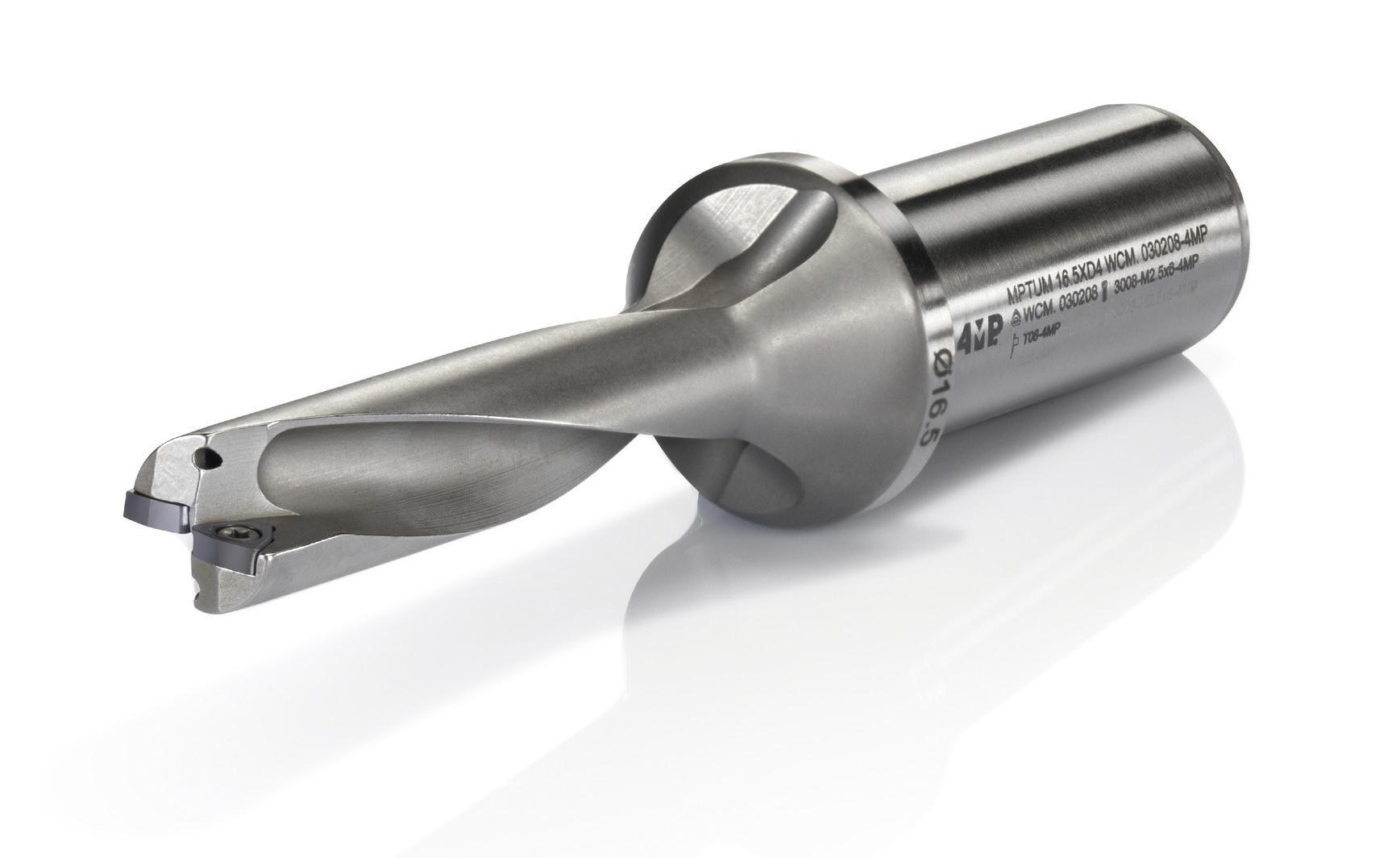
Foratura / Drilling
Drilling Foratura Informazioni tecniche Technical information 172 Drilling inserts Inserto di foratura Codifica Designation system 177 Accessori, inserti di foratura e adattatori eccentrici Spare parts, drilling inserts and eccentric adaptor 178 Adattatore eccentrico - Informazioni tecniche Technical informations eccentric adaptator 179 Parametri velocità di taglio Cutting parameters 180 Indexable drill Punta inserti Codifica Designation system 173 Punta inserti Indexable drill 174 171
FORATURA DRILLING
02
FORATURA DRILLING
Veloc�tà d� tagl�o e rotaz�one Cutt�ng speed
1000 * Vc
n = (tr/m�n)
* Dc
* Dc * n Vc = (m/m�n)
1000
Vc: Veloc�tà d� tagl�o / Cutt�ng speed (m/m�n)
: 5 3.14
Dc: D�ametro / D�ameter (mm)
n: Veloc�tà d� rotaz�one / Sp�ndle speed (tr/m�n)
Avanzamento per g�ro
Feed rate per rev.
Vf
f = (mm/rev)
n
F: Avanzamento per g�ro / Feed rate per rev. (mm/rev)
Vf: Avanzamento / Feed speed (mm/m�n)
n: Veloc�tà d� rotaz�one / Sp�ndle speed (rev/m�n)
Volume truc�olo Ch�p removal
Vf * * Dc
Q = (cm3/m�n)
4 * 1000
Q: Volume truc�olo / Ch�p removal (cm�/m�n)
Vf: Avanzamento / Feed speed (mm/m�n)
: 5 3.14
Dc: D�ametro della punta / Dr�ll d�ameter (mm)
Avanzamento per dente Feed rate per tooth
Vf
fz = (mm/z)
n * Z
fz: Avanzamento per dente / Feed rate per tooth(mm/z)
Vf: Avanzamento / Feed speed(mm/m�n)
n: Veloc�tà d� rotaz�one / Sp�ndle speed(rev/m�n)
Z: Numero d� dent� / Number of teeth
Tempo d� lavoraz�one T�me of cut
L Tc = (m�n)
Vf
Tc: Tempo d� lavoraz�one / T�me of cut (m�n)
L: Percorso d� lavoraz�one / Length of feed (mm)
Vf: Avanzamento / Feed speed (mm/m�n)
Copp�a d� forza Torque
Dc2 * Kc * f
Mc = (N*m)
8000
Mc: Copp�a d� forza / Torque
Dc: D�ametro della punta / Dr�ll d�ameter (mm)
Kc: Durezza del mater�ale / Un�t cutt�ng force (N/mm�)
F: Avanzamento per g�ro / Feed rate per rev. (mm/rev)
172
Informazioni tecniche
Technical information
Foratura / Drilling
173 MP 16 3 D3 4 X TUM 2 4MP W 5 C 6 M 7 T 8 05 9 03 10 08 11 Profond�tà d� foratura Dr�ll�ng Depth 4 D�ametro d� foratura Tool D�ameter 3 T�po d� porta-�nsert� Cutter Style 2 TUM: Punta � nsert � Indexable Dr � ll W S Forma dell’�nserto Insert Shape 5 C P Angolo d� spogl�a �nserto Clearance Angle 6 7° 11° T�po d� �nserto Insert Type 8 T U W Spec � ale / Spec al X J M N Q R A B C F G H Spessore �nserto Th�ckness 10 01 s = 1.59 T1 s = 1.98 02 s = 2.38 T2 s = 2.78 03 s = 3.18 T3 s = 3.97 04 s = 4.76 05 s = 5.56 06 s = 6.35 07 s = 7.94 09 s = 9.52 D�ametro cerch�o �nterno Inner C�rcle D�ameter 9 Ragg�o �nserto Corner Rad�us 11 01 r = 0.1 02 r = 0.2 04 r = 0.4 08 r = 0.8 12 r = 1.2 16 r = 1.6 24 r = 2.4 Tolleranza �nserto Tolerance Class 7 d m t A ± 0.025 ± 0.005 ± 0.025 C ± 0.025 ± 0.013 ± 0.025 E ± 0.025 ± 0.025 ± 0.025 F ± 0.013 ± 0.005 ± 0.025 G ± 0.025 ± 0.025 ± 0.130 H ± 0.013 ± 0.013 ± 0.025 J ± 0.05-0.15 ± 0.005 ± 0.025 K ± 0.05-0.15 ± 0.013 ± 0.025 L ± 0.05-0.15 ± 0.025 ± 0.025 M ± 0.05-0.15 ± 0.08-0.20 ± 0.130 N ± 0.05-0.15 ± 0.08-0.20 ± 0.025 U ± 0.08-0.25 ± 0.13-0.38 ± 0.130 Codifica Designation system PUNTA INSERTI INDEXABLE DRILLS Foratura / Drilling
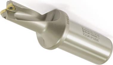
Punta inserti 2xD
Tipo di attacco: cilindrico con piatto. Rivestimento specifico.
Benefici: Elevata resistenza all’abrasione, Durezza superficiale 750-800 Vickers, migliore evacuazione del truciolo, maggiore durata dell’utensile.
Indexable drill 2xD
Connexion : cylindrical with flat. Specific coating.
Advantages : High wear resistance, high surface hardness 750-800 Vickers, better chip evacuation, improved tool life.
174 Foratura / Drilling Punta inserti Indexable drill 02 Articolo Reference Diametro DC (mm) Diameter DC (mm) LU (mm) LT (mm) Ø (mm) X Lg (mm)Tipo di inserto Insert type Eccentricità / O�set Codice Code Xmax radiale (mm) Xmax radial (mm) DC massima (mm) DC max (mm) MPTUM 16XD2 WCM.030208-4MP 16 32 110 25 X 56 WCM 030208 1,5 19 65 774 933 MPTUM 17XD2 WCM.030208-4MP 17 34 112 25 X 56 WCM 030208 1,5 20 65 774 968 MPTUM 18XD2 WCM.030208-4MP 18 36 114 25 X 56 WCM 030208 1,4 20,8 65 774 984 MPTUM 19XD2 WCM.030208-4MP 19 38 116 25 X 56 WCM 030208 1,2 21,4 65 774 992 MPTUM 20XD2 WCM.040208-4MP 20 40 118 25 X 56 WCM 040208 1,4 22,8 65 775 018 MPTUM 21XD2 WCM.040208-4MP 21 42 120 25 X 56 WCM 040208 1 23 65 775 026 MPTUM 22XD2 WCM.040208-4MP 22 44 122 25 X 56 WCM 040208 0,9 23,8 65 775 034 MPTUM 23XD2 WCM.040208-4MP 23 46 124 25 X 56 WCM 040208 0,8 24,6 65 775 050 MPTUM 24XD2 WCM.050308-4MP 24 48 126 25 X 56 WCM 050308 1,4 26,8 65 775 069 MPTUM 25XD2 WCM.050308-4MP 25 50 128 25 X 56 WCM 050308 1,4 27,8 65 775 077 MPTUM 26XD2 WCM.050308-4MP 26 52 130 25 X 56 WCM 050308 1,4 28,8 65 775 085 MPTUM 27XD2 WCM.050308-4MP 27 54 132 25 X 56 WCM 050308 1,4 29,8 65 775 107 MPTUM 28XD2 WCM.050308-4MP 28 56 134 25 X 56 WCM 050308 1,4 30,8 65 775 115 MPTUM 29XD2 WCM.050308-4MP 29 58 136 25 X 56 WCM 050308 1,4 31,8 65 775 131 MPTUM 30XD2 WCM.06T308-4MP 30 60 147 32 X 60 WCM 06T308 2,4 34,8 65 775 158 MPTUM 31XD2 WCM.06T308-4MP 31 62 149 32 X 60 WCM 06T308 2,3 35,6 65 775 166 MPTUM 32XD2 WCM.06T308-4MP 32 64 151 32 X 60 WCM 06T308 2,1 36,2 65 775 174 MPTUM 33XD2 WCM.06T308-4MP 33 66 153 32 X 60 WCM 06T308 1,9 36,8 65 775 182 MPTUM 34XD2 WCM.06T308-4MP 34 68 155 32 X 60 WCM 06T308 1,9 37,8 65 775 190 MPTUM 35XD2 WCM.06T308-4MP 35 70 157 32 X 60 WCM 06T308 1,8 38,6 65 775 204 MPTUM 36XD2 WCM.06T308-4MP 36 72 159 32 X 60 WCM 06T308 1,7 39,4 65 775 212 MPTUM 37XD2 WCM.06T308-4MP 37 74 161 32 X 60 WCM 06T308 1,6 40,2 65 775 220 MPTUM 38XD2 WCM.06T308-4MP 38 76 163 32 X 60 WCM 06T308 1,5 41 65 775 239 MPTUM 39XD2 WCM.06T308-4MP 39 78 165 32 X 60 WCM 06T308 1,3 41,6 65 775 247 MPTUM 40XD2 WCM.06T308-4MP 40 80 167 32 X 60 WCM 06T308 1 42 65 775 255
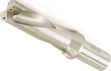
Punta inserti 3xD
Tipo di attacco: cilindrico con piatto. Rivestimento specifico.
Benefici: Elevata resistenza all’abrasione, Durezza superficiale 750-800 Vickers, migliore evacuazione del truciolo, maggiore durata dell’utensile.
Indexable drill 3xD
Connexion : cylindrical with flat. Specific coating.
Advantages : High wear resistance, high surface hardness 750-800 Vickers, better chip evacuation, improved tool life.
175 Foratura / Drilling Punta inserti Indexable drill 02 Articolo Reference Diametro DC (mm) Diameter DC (mm) LU (mm) LT (mm) Ø (mm) X Lg (mm)Tipo di inserto Insert type Eccentricità / O�set Codice Code Xmax radiale (mm) Xmax radial (mm) DC massima (mm) DC max (mm) MPTUM 16XD3 WCM.030208-4MP 16 48 126 25 X 56 WCM 0302081,5 19 65 775 263 MPTUM 17XD3 WCM.030208-4MP 17 51 129 25 X 56 WCM 0302081,5 20 65 775 298 MPTUM 18XD3 WCM.030208-4MP 18 54 132 25 X 56 WCM 0302081,4 20,8 65 775 328 MPTUM 19XD3 WCM.030208-4MP 19 57 135 25 X 56 WCM 0302081,2 21,4 65 775 336 MPTUM 20XD3 WCM.040208-4MP 20 60 138 25 X 56 WCM 0402081,4 22,8 65 775 344 MPTUM 21XD3 WCM.040208-4MP 21 63 141 25 X 56 WCM 0402081 23 65 775 352 MPTUM 22XD3 WCM.040208-4MP 22 66 142 25 X 56 WCM 0402080,9 23,8 65 775 360 MPTUM 23XD3 WCM.040208-4MP 23 69 144 25 X 56 WCM 0402080,8 24,6 65 775 387 MPTUM 24XD3 WCM.050308-4MP 24 72 150 25 X 56 WCM 0503081,4 26,8 65 775 395 MPTUM 25XD3 WCM.050308-4MP 25 75 153 25 X 56 WCM 0503081,4 27,8 65 775 409 MPTUM 26XD3 WCM.050308-4MP 26 78 156 25 X 56 WCM 0503081,4 28,8 65 775 417 MPTUM 27XD3 WCM.050308-4MP 27 81 159 25 X 56 WCM 0503081,4 29,8 65 775 433 MPTUM 28XD3 WCM.050308-4MP 28 84 162 25 X 56 WCM 0503081,4 30,8 65 775 441 MPTUM 29XD3 WCM.050308-4MP 29 87 165 25 X 56 WCM 0503081,4 31,8 65 775 476 MPTUM 30XD3 WCM.06T308-4MP 30 90 177 32 X 60 WCM 06T3082,4 34,8 65 775 484 MPTUM 31XD3 WCM.06T308-4MP 31 93 180 32 X 60 WCM 06T3082,3 35,6 65 775 492 MPTUM 32XD3 WCM.06T308-4MP 32 96 183 32 X 60 WCM 06T3082,1 36,2 65 775 506 MPTUM 33XD3 WCM.06T308-4MP 33 99 186 32 X 60 WCM 06T3081,9 36,8 65 775 514 MPTUM 34XD3 WCM.06T308-4MP 34 102 189 32 X 60 WCM 06T3081,9 37,8 65 775 522 MPTUM 35XD3 WCM.06T308-4MP 35 105 192 32 X 60 WCM 06T3081,8 38,6 65 775 530 MPTUM 36XD3 WCM.06T308-4MP 36 108 195 32 X 60 WCM 06T3081,7 39,4 65 775 549 MPTUM 37XD3 WCM.06T308-4MP 37 111 198 32 X 60 WCM 06T3081,6 40,2 65 775 557 MPTUM 38XD3 WCM.06T308-4MP 38 114 201 32 X 60 WCM 06T3081,5 41 65 775 565 MPTUM 39XD3 WCM.06T308-4MP 39 117 204 32 X 60 WCM 06T3081,3 41,6 65 775 573 MPTUM 40XD3 WCM.06T308-4MP 40 120 207 32 X 60 WCM 06T3081 42 65 775 581 MPTUM 45XD3 WCM.080412-4MP 45 135 237 40 X 70 WCM 0804123,3 51,6 69 109 004 MPTUM 50XD3 WCM.080412-4MP 50 150 252 40 X 70 WCM 0804122 54 69 109 012 MPTUM 55XD3 WCM.080412-4MP 55 165 267 40 X 70 WCM 0804120,8 56,6 69 109 020 MPTUM 60XD3 WCM.080412-4MP 60 180 282 40 X 70 WCM 0804120 60 69 109 039
Punta inserti
Indexable drill
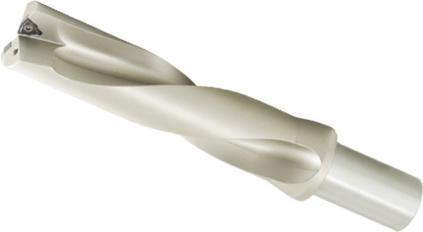
Punta inserti 4xD
Tipo di attacco: cilindrico con piatto. Rivestimento specifico.
Benefici: Alta resistenza all’abrasione, Durezza superficiale 750-800 Vickers, migliore evacuazione del truciolo, maggiore durata dell’utensile.
Indexable drill 4xD
Connexion : cylindrical with flat. Specific coating.
Advantages : High wear resistance, high surface hardness 750-800 Vickers, better chip evacuation, improved tool life.
176 Foratura / Drilling Articolo Reference Diametro DC (mm) Diameter DC (mm) LU (mm) LT (mm) Ø (mm) X Lg (mm)Tipo di insertos Insert type Eccentricità / O�set Codice Code Xmax radiale (mm) Xmax radial (mm) DC massima (mm) DC max (mm) MPTUM16XD4WCM.030208-4MP 16 64 142 25 X 56 WCM 030208 1,5 19 65 253 097 MPTUM17XD4WCM.030208-4MP 17 68 146 25 X 56 WCM 030208 1,5 20 65 253 100 MPTUM18XD4WCM.030208-4MP 18 72 150 25 X 56 WCM 030208 1,4 20,8 65 253 127 MPTUM19XD4WCM.030208-4MP 19 76 154 25 X 56 WCM 030208 1,2 21,4 65 253 135 MPTUM20XD4WCM.040208-4MP 20 80 158 25 X 56 WCM 040208 1,4 22,8 65 253 143 MPTUM21XD4WCM.040208-4MP 21 84 162 25 X 56 WCM 040208 1 23 65 253 151 MPTUM22XD4WCM.040208-4MP 22 88 166 25 X 56 WCM 040208 0,9 23,8 65 253 178 MPTUM23XD4WCM.040208-4MP 23 92 170 25 X 56 WCM 040208 0,8 24,6 65 253 194 MPTUM24XD4WCM.050308-4MP 24 96 174 25 X 56 WCM 050308 1,4 26,8 65 253 208 MPTUM25XD4WCM.050308-4MP 25 100 178 25 X 56 WCM 050308 1,4 27,8 65 253 216 MPTUM26XD4WCM.050308-4MP 26 104 182 25 X 56 WCM 050308 1,4 28,8 65 253 224 MPTUM27XD4WCM.050308-4MP 27 108 186 25 X 56 WCM 050308 1,4 29,8 65 253 240 MPTUM28XD4WCM.050308-4MP 28 112 190 25 X 56 WCM 050308 1,4 30,8 65 253 259 MPTUM29XD4WCM.050308-4MP 29 116 194 25 X 56 WCM 050308 1,4 31,8 65 253 275 MPTUM30XD4WCM.06T308-4MP 30 120 207 32 X 60 WCM 06T308 2,4 34,8 65 253 283 MPTUM 31XD4 WCM.06T308-4MP 31 124 211 32 X 60 WCM 06T308 2,3 35,6 65 775 611 MPTUM 32XD4 WCM.06T308-4MP 32 128 215 32 X 60 WCM 06T308 2,1 36,2 65 775 638 MPTUM 33XD4 WCM.06T308-4MP 33 132 219 32 X 60 WCM 06T308 1,9 36,8 65 775 646 MPTUM 34XD4 WCM.06T308-4MP 34 136 223 32 X 60 WCM 06T308 1,9 37,8 65 775 654 MPTUM 35XD4 WCM.06T308-4MP 35 140 227 32 X 60 WCM 06T308 1,8 38,6 65 775 662 MPTUM 36XD4 WCM.06T308-4MP 36 144 231 32 X 60 WCM 06T308 1,7 39,4 65 775 670 MPTUM 37XD4 WCM.06T308-4MP 37 148 235 32 X 60 WCM 06T308 1,6 40,2 65 775 689 MPTUM 38XD4 WCM.06T308-4MP 38 152 239 32 X 60 WCM 06T308 1,5 41 65 775 697 MPTUM 39XD4 WCM.06T308-4MP 39 156 243 32 X 60 WCM 06T308 1,3 41,6 65 775 700 MPTUM 40XD4 WCM.06T308-4MP 40 160 247 32 X 60 WCM 06T308 1 42 65 775 719
02
177 Inserto di foratura Drilling insert T 4 M 3 C 2 A 8 W 1 02 6 08 7 UG 9 03 5 Forma Shape 1 S W 90° 80° Angolo d� spogl�a Clearance Angle 2 A B C D E F G N P O Altr � angol � d � spogl � a Other clearance angle 11° 20° 25° 30° 0° 3° 5° 7° 15° Romp�truc�olo Ch�p breaker code 9 UG Universale UG Universel 01 = 1.59 T1 = 1.98 02 = 2.38 03 = 3.18 T3 = 3.97 04 = 4.76 05 = 5.56 06 = 6.35 07 = 7.94 09 = 9.525 11 = 11.11 12 = 12.70 14 = 14.29 15 = 15.88 Spessore / Th�ckness 6 T�po d� �nserto Clamp�ng Type 4 A B C F G H J M N O R T U W X 70°-90° 70°-90° 70°-90° Spec � ale Spec � al 40°-60° 40°-60° 40°-60° 40°-60° Tolleranza Tolerance 3 d m s A +/- 0,025 +/- 0,005 +/- 0,025 F +/- 0,013 C +/- 0,025 +/- 0,013 H +/- 0,013 E +/- 0,025 +/- 0,025 G +/- 0,13 J -0.05 a +0.05 +/- 0,005 +/- 0,025 K +/- 0,13 L +/- 0,025 M -0.08 a +0.20 +/- 0,13 N +/- 0,025 U -0.08 a +0.25 +/- 0,13+/- 0,13 Cerchio inscritto In.Circle (mm) Codice code Lunghezza Length Codice code Lunghezza Length 5,56 03 3,8 6,4 06 6,35 04 4,3 7,94 05 5,4 8,0 08 8,0 9,525 09 9,525 06 6,5 12,7 12 12,7 08 8,7 Lunghezza del tagl�ente / Cutt�ng Edge Length 5 L Type W L Type S Ragg�o d� �nserto / Corner Rad�us 7 01 = 0,1 02 = 0,2 04 = 0,4 08 = 0,8 12 = 1,2 16 = 1,6 20 = 2,0 24 = 2,4 28 = 2,8 32 = 3,2 40 = 4,0 48 = 4,8 56 = 5,6 64 = 6,4 x = autres /others Codice Code Disegno / Illustration Angolo della spoglia / Edge shape V Bordi taglienti Sharp cutting edge A Bordi arrotondati Honed cutting edge C Bordi negativi Negative land Preparaz�one del tagl�ente / Edge Preparat�on 8 70°-90°
Foratura / Drilling
CODIFICA DESIGNATION SYSTEM
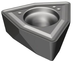
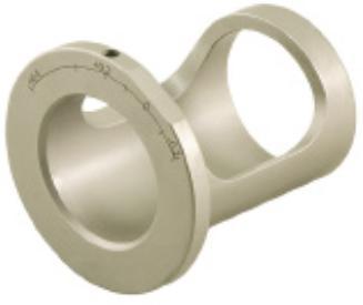
Accessori, inserti di foratura e adattatori eccentrici
Spare parts, drilling inserts and eccentric adaptor
Inserto WC..
La geometria UG unita al grado DP35BM è adatta per materiali P, M e S. Eccellente controllo del truciolo nei materiali teneri. Consigliato per lavorazioni con utensile rotativo o fisso.
Eccellente resistenza all’usura grazie al rivestimento PVD.
178 Foratura / Drilling Accessori Accessories Vite e chiave Screw and wrench Dimensioni (mm) Dimensions (mm) Accessori Spare parts Diametro punte Cutter diameter Vite Screw Chiave di serraggio Wrench Articolo / Reference Codice / Code Articolo / Reference Codice / Code Ø16 - 19 3008-M2.5X6-4MP 65 252 120 80-T08-4MP 65 252 171 Ø20 - 23 3008-M2.5X6-4MP 65 252 120 80-T08-4MP 65 252 171 Ø24 - 29 1008-M3X8-4MP 65 252 104 80-T08-4MP 65 252 171 Ø30 - 40 1510-M3.5X9-4MP 65 252 112 80-T10-4MP 65 252 198 Ø41 - 60 4015-M4X11-4MP 67 467 744 80-T15-4MP 65 252 201
Dimensioni (mm) Dimensions (mm) Materiali ISO Materials ISO Articolo Reference Codice Code l d s r h P M S K N H WCMT 030208A-UG DP35BM-4MP 67 064 151 3,85,562,380,82,8 WCMT 040208A-UG DP35BM-4MP 67 064 178 4,36,352,380,8 3 WCMT 050308A-UG DP35BM-4MP 67 064 186 5,47,943,180,83,4 WCMT 06T308A-UG DP35BM-4MP 67 064 194 6,59,5253,970,83,9 WCMT 080412-UG DP35BM-4MP 69 108 997 8,712,74,761,24,4
Inserts
WC.. The UG geometry combined with the DP35BM grade is suitable for
M and S
for
machining. Excellent wear resistance due to the PVD coating. Applicazione principale / F � rst cho � ce Applicazione secondaria / Second cho � ce Adattatore eccentrico per punte MPTUM Utilizzo come utensile rotativo, consente di aumentare o ridurre il diametro di foratura
drills
or
drill diameter. Articolo Reference Dimensioni (mm) Dimensions (mm) Codice Code Diametro D Diameter D Diametro D1 Diameter D1 Lunghezza L Length L DEX-2025-4MP 20 25 44 69 208 746 DEX-2532-4MP 25 32 46 69 208 754 DEX-3240-4MP 32 40 55 69 208 762 (1) L D1 5 3 typ D
Inserti
Insert
P,
materials. Excellent chip control in soft materials. Suitable
rotating and non-rotating
Eccentric adaptor for MPTUM
Use in rotating tool, increases
decreases the
02
FORATURA DRILLING
Adattatore eccentrico - Informazioni tecniche
Technical informations eccentric adaptator
Per l’utilizzo su un centro di lavoro, il diametro nominale della punta può essere modificato spostando l’asse della punta rispetto all’asse del mandrino.
In m � ll � ng mach � nes, the d � ameter of the � nsert dr � ll can be changed by sh � ft � ng the ax � s of the dr � ll relat � ve to the sp � ndle ax � s.
Porta-utensili / Toolholder
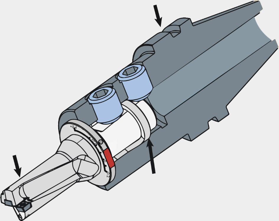
Perno di regolazione radiale (non fornito) / Rad � al adjustment p � n (not � ncluded)
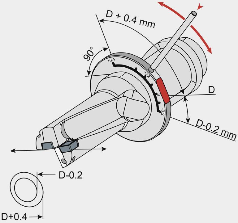
Cond�z�on�
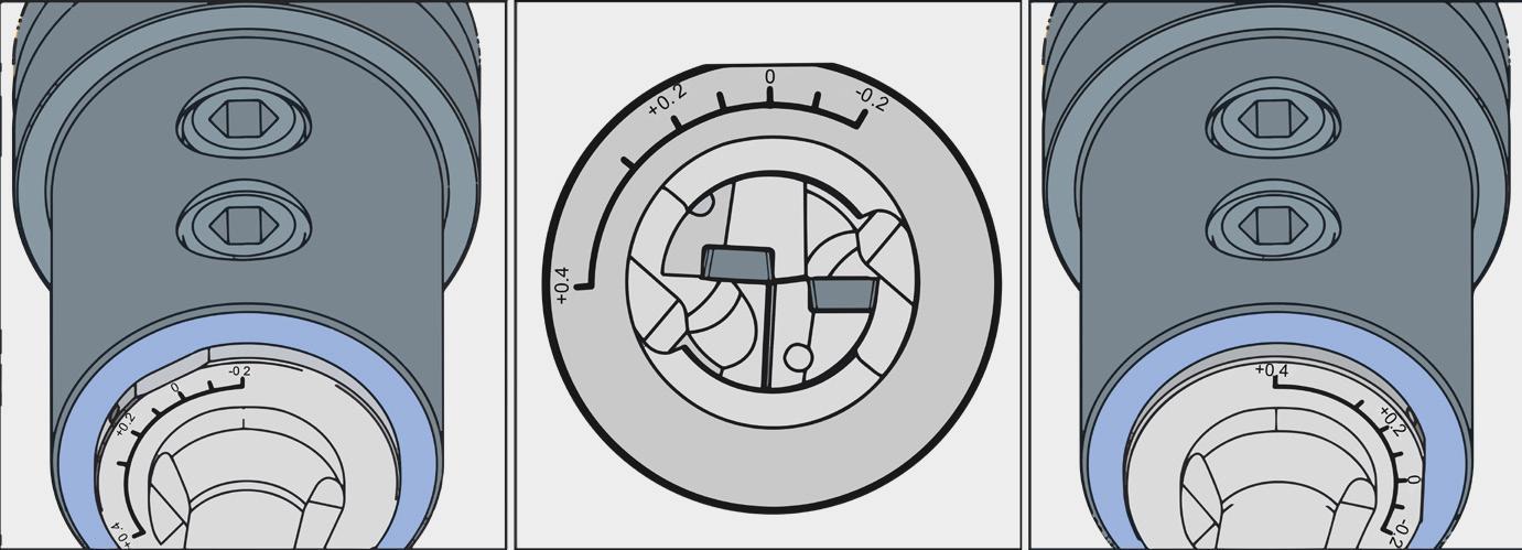
Diametri del foro: 24,8 mm
Hole D � ameter : 24.8 mm

Diametro di foratura 25 mm
Dr � ll d � ameter : 25 mm
Posizione 0 = Ø nominale
Diametri del foro: 25 mm
Hole D � ameter : 25 mm

Diametro di foratura 25 mm
Dr � ll d � ameter : 25 mm
Diametri del foro: 25,4 mm
Hole D � ameter : 25,4 mm

Diametro di foratura 25 mm
Dr � ll d � ameter : 25 mm
Riduzione dei parametri di taglio consigliati / Cutt � ng parameters adjustment to apply
Lunghezza diametro Length d � ameter
Le tacche di regolazione devono essere posizionate perpendicolarmente al piano di serraggio della punta. Per facilitare la rotazione dell’adattatore, è possibile inserire un perno di regolazione o una chiave nel foro dell’adattatore. Sbloccare la vite del portautensili prima di regolare l’adattatore.
The adjustment mark � ngs should be located perpend � cular to the flat on the shank of the � ndexable dr � ll. To fac � l � tate the rotat � on of the adaptor, a metal rod or a screw key may be � nserted � nto a hole on the eccentr � c adaptor flange. Unlock the toolholder screw before adjust � ng adaptor.
179
ll MPTUM
Adattatore eccentrico / Eccentr � c adaptor Punta / Dr �
d� tagl�o Cutt�ng
cond�t�ons
100% 90% 80% 70% 60% 50% 40% 2xD 3xD 4xD 5xD
Foratura / Drilling
180
Materiali / Materials Inserti di foratura / WC drilling inserts Gradi e parametri di taglio consigliati / Grade applications & cutting parameters recommended ISO Classificazione dei materiali / Material classification AFNOR DIN Durezza / Tensile strength (N/mm2) Durezza / Tensile strength (N/mm2) DP35BM Possibilità Possibilities Avanzamento Feed (mm/rev) PVD rivestito coated Scelta N1 Best choice Scelta N2 2nd choice P30-45 M30-45 S 30-45 Velocità di taglio Cutting speed (m/min) ø 16mm ~ ø 19mm ø 20mm ~ ø 23mm ø 24mm ~ ø 29mm ø 30mm ~ ø 40mm ø 41mm ~ ø 60mm Min Max WCMT 030204AUG WCMT 040204AUG WCMT 050308AUG WCMT 06T308AUG WCMT 080412AUG P Acciaio non legato Non-alloyed steel S300 - 16NC6 9SMn3615CrNi6 <600 <180 150 220 0,04-0,0650,07-0,090,07-0,10 0,08-0,11 0,09-0,13 XC18 - 16NC6 Ck15 - 15NiCr6<950 <280 140 200 0,05-0,070,09-0,090,07-0,10 0,08-0,11 0,09-0,13 Acciaio legato Alloyed steel 42CD4 - XC60 42CrMo4Ck60 700-950 200-280 130 190 0,05-0,090,065-0,140,08-0,16 0,10-0,18 0,10-0,20 Z40CDV4 X40CrMoV5 950-1200 280-355 90 170 0,04-0,07 0,065-0,110,07-0,14 0,09-0,15 0,10-0,18 55NCDV7 - Z40C14 55NiCrMoV6X30Cr13 1200-1400 355-415 80 160 0,04-0,065 0,05-0,9 0,07-0,10 0,08-0,12 0,09-0,13 M Acciaio inossidabile Duplex stainless steel Z2CNDN22,05 X2CrNiMoN22-5 778 230 90 180 0,04-0,070,065-0,110,08-0,140,08-0,110,09-0,13 Acciaio inossidabile austenitico Austenitic stainless steel 304L - 316L Z6CN18,09 304, 316, X6CrNi18-10 675 200 60 120 0,04-0,0650,065-0,100,08-0,120,08-0,100,08-0,11 Acciaio inossidabile molto tenace e altamente legato Precipitation hardening stainless steel Z3CNDN25,07Az X2CrNiMoN25 7 4 1013 300 40 90 - - - -K Ghisa grigia Grey cast iron FT20D - FT40D GG20, GG40 700 220 - - - - - - -Ghisa lamellare Nodular cast iron FGS400-12FGS700-2 GGG40, GGG70 880 260 - - - - - - -Ghisa malleabile Malleable cast iron P540/5 GTS 55 04 800 250 - - - - - - -S Superleghe a base di ferro Fe-based alloy Discalloy 943 280 20 40 - - - -Superleghe a base di cobalto Co-based alloy Stellite 21 1076 320 15 35 - - - -Superleghe a base di nichel Ni-based alloy Inconel 718 1177 350 15 35 - - - -Lega di titanio Ti-alloy TiAl6V4 1262 370 20 40 0,05-0,100,06-0,11 0,07-0,120,08-0,130,08-0,14 N Alluminio < 9% Aluminum < 9% A-U4SG AlCuSiMn 260 75 - - - - - - -Lega di alluminio Aluminum alloy A-S10G G-AlSi10Mg 447 130 - - - - - - -H Acier cémenté à outils trempés au manganèse Hardened steel 100C6 Z40CDV5 Z120M12 100Cr6 X40CrMoV5 1 X120Mn12 - 50-60HRC - - - - - - -Fonte blanche Chilled cast iron Grado 2B Grade 2B FB Ni4 Cr2HC - 55HRC - - - - - - -*I parametri di taglio e�ettivi devono essere regolati in base a fattori quali la rigidità della macchina il corpo dell’utensile, le condizioni del pezzo e il refrigerante. *Above chart for general cutting conditions. The actual selection should be adjusted according to factors such as machine rigidity, tool body, workpiece conditions and coolant.
Foratura / Drilling
Parametri velocità di taglio Cutting parameters
FORATURA DRILLING
181
CONVERSIONE
INTERNATIONAL MATERIAL CONVERSION TABLE 02 Acciaio strutturale (P) Acciaio per utensili (P) 183 184 Acciaio inossidabile strutturale (M) Acciaio inossidabile austenitico (M) 184 Lega di nichel (S) 185 Lega di cobalto (S) 185 Lega di titanio (S) 185 Ghisa lamellare (K) 185 Ghisa grigia (K) 186 Leghe di alluminio (N) 186 182 Structural steel Tool steel Structural stainless steel Austenitic stainless steel Ni based alloy Co based alloy Ti-alloy Nodular cast iron Grey cast iron Al based alloy
TABELLA INTERNAZIONALE DI
MATERIALI
182
ISO Paesi e norme / Country and standard France InternationalGermany U.S.A. U.K. Sweden Italy Spain Japan AFNOR DIN W.-nr AISI/SAE BS EN SS UNI UNE JIS Acciaio strutturale / Structural steel P CC12 C15 1,040 1015 080M15 - 1350 C15C16 F.111CC20 C22 1,040 1020 050A20 2C 1450 C20C21 F.112CC35 C35 1,050 1035 060A35 - 1550 C35 F.113CC45 C45 1,050 1045 080M40 - 1650 C45 F.114- C55 1,054 1055 070M55 - 1655 C55 -CC55 C60 1,060 1060 080A62 43D - C60 -S250 9SMn28 1,072 1213 230M07 - 1912 CF9SMn28 11SMn28 SUM22 S250Pb 9SMnPb28 1,072 12L13 - - 1914 CF9MnPb2811SMnPb28 SUM22L 10PbF2 10SPb20 1,072 - - - - CF10Pb20 10SPb2035MF4 35S20 1,073 1140 212M36 8M 1957 - F210GS300 9SMn36 1,074 1215 240M07 1B - CF9SMn3612SMn35S300Pb 9SMnPb36 1,074 12L14 - - 1926 CF9SMnPb3612SMnP3555S7 55Si9 1,090 9255 250A53 45 2085 55Si8 56Si760SC7 60SiCr7 1,096 9262 - - - 60SiCr8 60SiCr8XC12 Ck15 1,114 1015 080M15 32C 1370 C16 C15K S15C 35M5 40Mn4 1,116 1039 150M36 15 - - -- Ck25 1,116 1025 - - - - - S25C 40Mn5 36Mn5 1,117 1335 - - 2120 - 36Mn5 SMn438(H) 20M5 28Mn6 1,117 1330 150M28 14A - C28Mn - SCMn1 XS38TS Cf35 1,118 1035 060A35 - 1572 C36 - S35C XC42 45 1,119 1045 080M46 - 1672 C45 C45K S45C XC45 Ck55 1,120 1055 070M55 - - C50 C55K S55C XC48TS Cf53 1,121 1050 060A52 - 1674 C53 - S50C XC60 Ck60 1,122 1060 080A62 43D 1678 C60 - S58C - Ck101 1,127 1095 060A96 - 1870 - - SUP4 X120M12 X120Mn12 1,340 - Z120M12 - - XG120Mn12X120Mn12 SCMnH/1 100C6 100Cr6 1,351 52100 534A99 31 2258 100Cr6 F.131 SUJ2 15D3 15Mo3 1,542 ASTM A204Gr.A 1501-240 - 2912 16Mo3KW 16Mo3- 16Mo5 1,543 4520 1503-245420 - - 16Mo5 16Mo516N6 14Ni6 1,562 ASTM A350LF5 - - - 14Ni6 15Ni6- X8Ni9 1,566 ASTM A353 1501-509; 510 - - X10Ni9 XBNi09Z18N5 12Ni19 1,568 2515 - - - - -35NC6 36NiCr6 1,571 3135 640A35 111A - - - SNC236 14NC11 14NiCr10 1,573 3415 - - - 16NiCr11 15NiCr11 SNC415 (H) 12NC15 14NiCr14 1,575 34153310 655M13655A12 36A - -SNC815 (H) INTERNATIONAL MATERIAL CONVERSION TABLE
TABELLA INTERNAZIONALE DI CONVERSIONE DEI MATERIALI
ISO Paesi e norme / Country and standard France InternationalGermany U.S.A. U.K. Sweden Italy Spain Japan AFNOR DIN W.-nr AISI/SAE BS EN SS UNI UNE JIS 40NCD3 36CrNiMo4 1,651 9840 816M40 11038CrNiMo4 (KB) 35CrNiMo420NCD2 21NiCrMo2 1,652 8620 850M20 362 2503 20NiCrMo220NiCrMo2 SNCCM220 (H) - 40NiCrMo2 1,655 8740 311-Type7 -40NiCrMo2 (KB) 40NiCrMo2SNC240 35NCD6 34CrNiMo6 1,658 4340 817M40 24 2541 35CrNiMo6 (KB) -18NCD6 17CrNiMo6 1,659 - 820A16 - - - 14CrNiMo112C3 15Cr3 1,702 5015 523M15 - - - - SCr415(H) 32C4 34Cr4 1,703 5132 530A32 18B - 34Cr4(KB) 35Cr4 SCr430(H) 42C4 41Cr4 1,704 5140 530M40 18 - 41Cr4 42Cr4 SCr440(H) - 42Cr4 1,705 5140 - - 2245 - 42Cr4 SCr440 16MC5 16MnCr15 1,713 5115 (527M20) - 2511 16MnCr15 16MnCr1555C3 55Cr3 1,718 5155 527A60 48 - - - SUP9(A) 25CD4 25CrMo4 1,722 4130 1717CDS110- 2225 25CrMo4 (KB) 55Cr3 SCM420; SCM430 35CD4 34CrMo4 1,722 4137;4135 708A37 19B 2234 35CrMo4 34CrMo4 SCM432; SCRRM3 42CD4TS 41CrMo4 1,722 4140;4142 708M40 19A 2244 41CrMo4 41CrMo4 SCM440 42CD4 42CrMo4 1,723 4140 708M40 19A 2244 42CrMo4 42CrMo4 SCM440(H) 12CD4 15CrMo5 1,726 - - - 2216 - 12CrMo4 SCM415(H) 15CD3.5; 13CrMo44 1,734 ASTMA182F11; F12 1501-620Gr.27- - 14CrMo44 14CrMo4515CD4.5 30CD12 32CrMo12 1,736 - 722M24 40B 2240 32CrMo12 F.124.A12CD9;10 10CrMo910 1,738 ASTMA182F.22 1501622Gr.31;45 - 2218 12CrMo9,10TU.H- 14MoV63 1,7721503-660440 - - - 13MoCrV650CV4 50CrV4 1,816 6150 735A50 47 2230 50CrV4 51CrV4 SUP10 40CAD6,12 41CrAlMo7 1,851 - 905M39 41B 2940 41CrAlMo7 41CrAlMo7- 39CrMoV1391,852 - 897M39 40C - 36CrMoV12-Acciaio per utensili / Tool steel P Y1105 C105W1 1,155 W.110 - - 1880 C98KU C100KU F.515 F.516Y2120 C125W 1,166 W.112 - - - C120KU (C120) SK20 Y100C6 100Cr6 1,207 L3 BL3 - - - 100Cr6Z200Cr12 X210Cr12 1,208 D3 BD3 -X210Cr13KU X250Cr12KU X210Cr12 SKD1 Z40CDV5 X40CrMoV5 11,234 H13 BH13 - 2242 X35CrMoV05KU X40CrMoV51KU X40CrMoV5SKD61 Z100CDV5 X100CrMoV5 11,236 A2 BA2 - 2260 X100CrMoV51KU X100CrMoV5SKD12 105WC13 105WCr6 1,242 - - - 2140 10WCr6 107WCr5KU 105WCr5 SKS31 - SKS2 SKS3 - X210CrW12 1,244 - - - 2312 X215CrW12 1KU X210CrW12SKD2 - 45WCrV7 1,254 S1 BS1 - 2710 45WCrV8KU45WCrSi8Z30WCV9 X30WCrV93 X30WCrV93KU 1,258 H21 BH21 -X28W09KU X30WCrV9 3KU X30WCrV9SKD5 - X165CrMoV 121,260 - - - 2310 X165CrMoW12KU X160CrMoV12SKD11 55NCDV7 55NiCrMoV61,271 L6 - - - - F.250.S SKT4 TABELLA INTERNAZIONALE DI CONVERSIONE DEI MATERIALI 183 INTERNATIONAL MATERIAL CONVERSION TABLE
ISO Paesi e norme / Country and standard France InternationalGermany U.S.A. U.K. Sweden Italy Spain Japan AFNOR DIN W.-nr AISI/SAE BS EN SS UNI UNE JIS P Y1105V 100V1 1,283 W210 BW2 - - - - SKS43 Z85WDKCVS6-5-2-5 1,324 - - - 2723 HS6-5-2-5 HS6-5-2-5 SKH55 Z80WKCV 10-05-04-01 S18-1-2-5 1,326 T4 BT4 -X78WCo1805KU HS18-1-1-5 SKH3 Z85WDCV 06-05-04-02 S6-5-2 1,334 M2 BM2 - 2722 X82WMo0605KU HS6-5-2 SKH9 Z100WCWV 09-02-04-02 S2-9-2 1,335 M7 - -Z- 2782 HS2-9-2 HS2-9-2Z80WCV 18-04-01 S18-0-1 1,336 T1 BT1 - - X75W18KU HS18-0-1 SKH2 - S6-5-3 - M3 - - - - - SKH52 - - - M42 BM42 - - - - SKH59 Acciaio inossidabile strutturale / Structural stainless steel
Z6C13 403 1,4 403 403S17 - 2301 X6Cr13 F.3110 SUS403 - - 1,400 - - - - - F.8401X12Cr13 410 1,401 410 410S21 56A 2302 X12Cr13 F.3401 SUS410 X8Cr17 430 1,402 430 430S15 60 220 X8Cr17 F.3113 SUS430 X20C13 410 1,402 40 S62 56B;56C - X20C13 F.3401 SUS410 - - 1,403 - 420C29 56B - - - SCS2 X40Cr14 - 1,403 - 420S45 56D 2304 X40Cr14 F.3405 SUS420J2 X16CNi16 431 1,406 431 431S29 57 2321 X16CNi16 F.3427 SUS431 X10CrS17 430F 1,410 430F - - 2383 X10CrS17 F.3117 SUS430F X8CrMo17 434 1,411 434 434S17 - 2325 X8CrMo17 - SUS434 - - 1,431 - 425C11 - - - - SCS5 - - 1,441 - 316C16 - - - F.8414 SCS14 X45CrSi8 HW3 1,472 HW3 401S45 52 - X45CrSi8 F.322 SUH1 X10CrAl12 405 1,472 405 403S17 - - X10CrAl12 F.311 SUS405 X8Cr17 430 1,474 430 430S15 60 - X8Cr17 F.3113 SUS430 X80CrSiNi20HNV6 1,476 HNV6 443S65 59 - X80CrSiNi20F.320V SUH4 X16Cr26 446 1,476 446 - - 2322 X16Cr26 - SUH446 Acciaio inossidabile austenitico / Austenitic stainless steel Z6CN18.09 X5CrNi1810 1,430 304 304S15 58E 2332 X5CrNi1810 F.3551 F.3541; F.3504 SUS304 Z10CNF18.09X10CrNiS1891,431 303 303S21 58M 2346 X10CrNiS18.09F.3508 SUS303 Z2CN18.10 X2CrNi1911 1,431 304L 304S12 - 2352 X2CrNi18.11 F.3503 SCS19 Z6CN18.10MG-X6CrNi1891,431 - 304C15 - - - - SCS13 Z12CN17.07 X12CrNi177 1,431 301 - - 2331 X12CrNi1707F.3517 SUS301 Z2CN18.10 X2CrNiN18101,431 304LN 304S62 - 2371 - - SUS304LN Z6CN18.09 X5CrNi189 1,435 304 304S31 58E - X5CrNi1810 - SUS304 1,440 X5CrNi Mo1712 1,440 316 316S16 Z6CND 17.11 2347 X5CrNiMo1712F.3543 SUS316 Z2CND17.13 X2CrNi MoN17133 1,443 316LN - - 2375 - - SUS316LN TABELLA INTERNAZIONALE DI CONVERSIONE DEI MATERIALI 184 INTERNATIONAL MATERIAL CONVERSION TABLE
M
SNC20T NiCr20Ti 2,463 - HR5.203-4
- NiCu30AL3Ti 2,438 4676 3072-76
Lega di cobalto / Co based alloy
KC20WN CoCr20W15Ni- 5537C,AMS
185 ISO Paesi e norme / Country and standard France InternationalGermany U.S.A. U.K. Sweden Italy Spain Japan AFNOR DIN W.-nr AISI/SAE BS EN SS UNI UNE JIS
Z2CDN17.13 X2CrNi Mo18143 1,444 316L 316S12 - 2353 X2CrNiMo1713- SCS16 Z2CND19.15 X2CrNi Mo17133 1,444 317L 317S12 - 2367 X2CrNiMo18.16- SUS317L - X8CrNiMo2751,446 329L - - 2324 -SUS329L; SCH11; SCS11 ISO France International Germany U.S.A U.K. Sweden Italy Spain Japan AFNOR DIN W.-nr AISI/SAE BS SS UNI UNE JIS
M
Lega di nichel / Ni based alloy
NC12AD S-NiCr13A16MoNb LW2 4670 5391 mar-46 - - -NiCo15Cr10MoAlTi LW2 4674 AMS 5397 - - - -ZSNCDT42 NiFe35Cr14MoTiLW2.4662 5660 - - - -NC19eNB NiCr19Fe19NbMo LW2.4668
- - - -
2,463 - Hr401.601 - - - -
- - - - -
NiCr19Fe19NbMo LW2.4668 AMS 5544 - - - -NC22FeD - 2,460 5390A - - - -NC22FeDNB NiCr22Mo9Nb2,486 5666 - - - - -
5383 HR8
NC20TA NiCr20TiAk
NC19KDT NiCr19Co11MoTi2,497 AMS 5399
NC20K14
- - - -
- - - -
- - - -KC22WN CoCr22W14NiLW2.4964 5772 - - - -Lega di titanio / Ti-alloy T-A5E TiAl5Sn2.5 3.7115.1 UNS R54520TA14/17 - - -UNS R56400 - - - - - - -UNS R56401 TiAl6V4 3.7165.1 - TA10-13/TA28- T-A6V -- TiAl5V5Mo5Cr3 - - - - - -TiAl4Mo4Sn4Si0.5 3,719 - - - - -ISO France Germany U.S.A. U.K. France Sweden Italy Spain Japan AFNOR W.-nr AISI/SAE EN AFNOR SS UNI UNE JIS Ghisa nodulare / Nodular cast iron K FGS370-17 GGG40 60-40-18 400/17 FGS370-17 0717-02 GS370-17 FGE38-17 FCD400 FGS400-12 65-45-12 420/12 FGS400-12 GS400-12 FGE42-12 FCD450 FGS500-7 GGG50 70-50-05 500/7 FGS500-7 0727-02 GS500-7 FGE50-7 FCD500 FGS600-2 GGG60 80-60-03 600/7 FGS600-2 0732-03 GS600-2 FGE60-2 FCD600 FGS700-2 GGG70 100-70-03 700/2 FGS700-2 0737-01 GS700-2 FGE70-2 FCD700
TABELLA INTERNAZIONALE DI CONVERSIONE DEI MATERIALI INTERNATIONAL MATERIAL CONVERSION TABLE
186 ISO France Germany U.S.A. U.K. France Sweden Italy Spain Japan AFNOR W.-nr AISI/SAE EN AFNOR SS UNI UNE JIS K FGS800-2 GGG80 120-90-02 800/2 FGS800-2 0864-03 GS800-2 FGE80-2 FCD800 900/2 Ghisa grigia / Grey cast iron FGL400 GG40 NO.60 FGL400 140 FGL350 GG35 NO.50 350 FGL350 135 G35 FG35 FC350 FGL300 GG30 NO.45 300 FGL300 130 G30 FG30 FC300 FGL250 GG25 NO.35 250 FGL250 125 G25 FG25 FC250 FGL200 GG20 NO.30 200 FGL200 120 G20 FG20 FC200 FGL150 GG15 NO.20 150 FGL150 115 G15 FG15 FC150 100 110 G10 FC100 ISO France International Germany U.S.A. U.K. Sweden Italy Spain Japan AFNOR DIN W.-nr AISI/SAE BS SS UNI UNE JIS Leghe di alluminio / Al based alloy N A-S7G Al-Si7Mg(Fe) ~AlSi7Mg 356 LM25 4244 3599 - AC4C A-S7G03 Al-Si7Mg AlSi7Mg A356.0 2L99 - 8024 - AC4C A-S13 Al-Si12 AlSi12 413;B413.0 LM6 4261 4514 - AC3A A-S9G;A-S10G~Al-Si10Mg AlSi9Mg 360 LM9 4253 3051 - AC4A - Al-Si5 AlSi5Mg A 443.0 - - 5077 -- Al-Si5Fe - B443.0 - - GD-AlSi5Fe -- (AlSi7Fe) - A444.0 - - - -~A-S12 Al-Si12Fe - 413 LM20 4260 5079 - ADC1
INTERNATIONAL MATERIAL
TABELLA INTERNAZIONALE DI CONVERSIONE DEI MATERIALI
CONVERSION TABLE
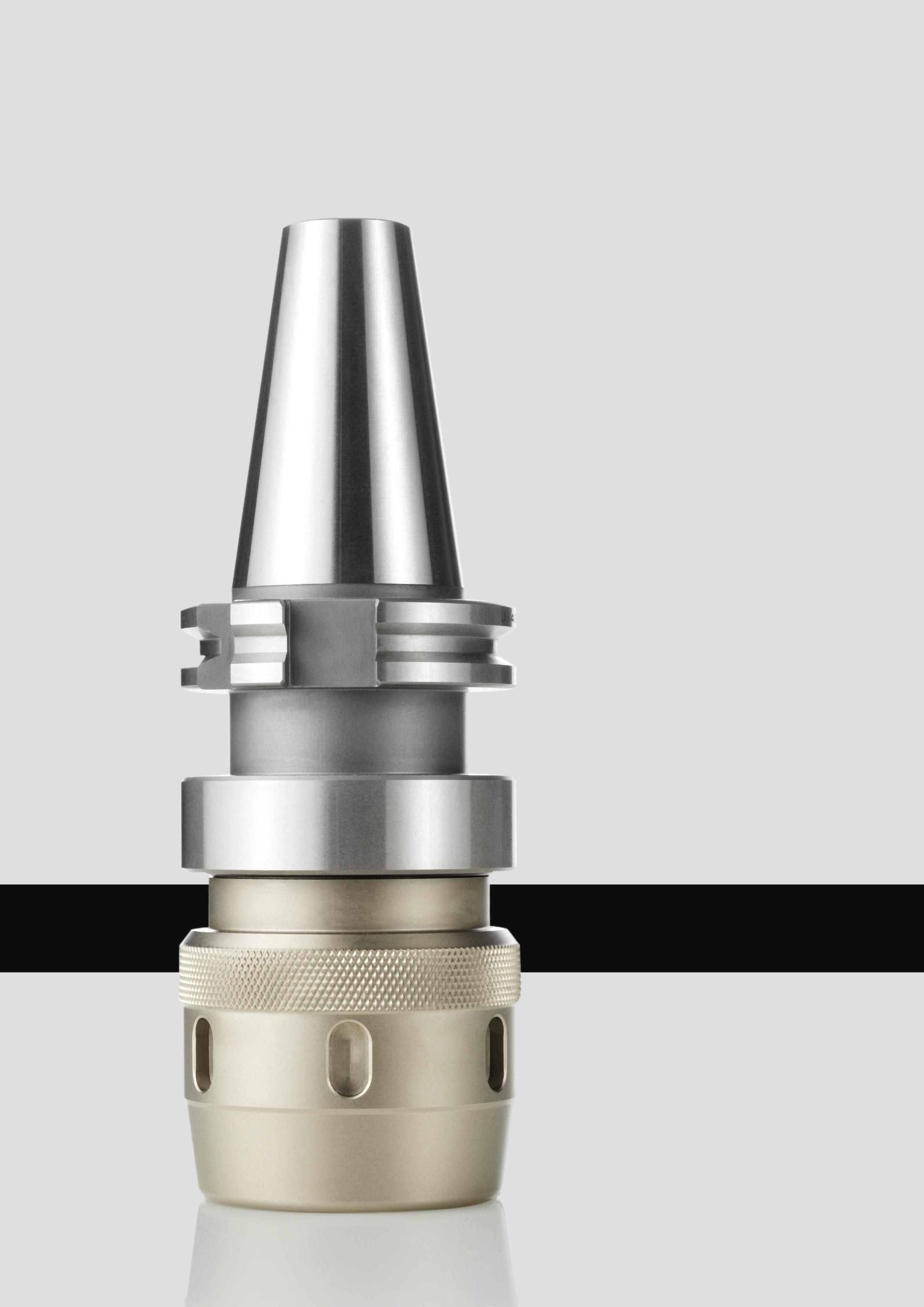
03
utensili Tooling systems 187
Accessori per macchine
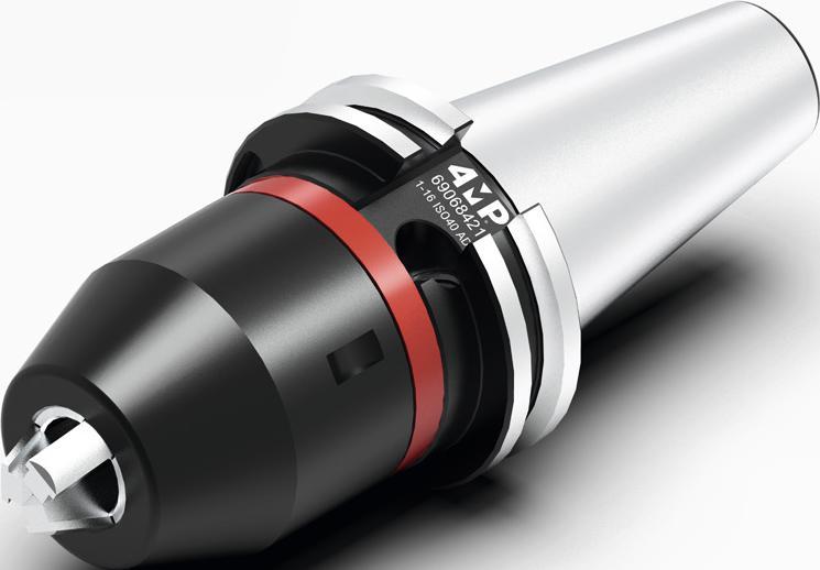
Accessori per macchine utensili / Tooling systems
MACCHINE
TOOLING SYSTEMS 03 188 Milling toolholders - BT Portautensili per fresatura - BT (JIS 6339) Informazioni tecniche Technical information 189 Portautensili BT (JIS 6339) Toolholders BT (JIS 6339) 190 Milling toolholders - SK Portautensili per fresatura - ISO (DIN 69871) Informazioni tecniche Technical information 194 Portautensili ISO (DIN 69871) Toolholders SK (DIN 69871) 195 Straight shank and morse tappers toolholders Portautensili cilindrici e coni morse Portautensili cilindrici Straight shank toolholders 203 Portautensili cono morse Morse tapper toolholders 204 Milling toolholders - HSK-A Portautensili per fresatura - HSK-A (DIN 69893-1) Informazioni tecniche Technical information 199 Portautensili HSK-A (DIN 69893-1) Toolholders HSK-A (DIN 69893-1) 200 Sleeves, collets and accessories Bussole, pinze e accessori Bussole di maschiatura con frizione Bush for tapping with clutch 206 Pinze di serraggio Collets 207 Accessori per attacchi Accessories for toolholders 213 Bussole di riduzione cilindriche per tornio Cylindrical reduction sleeve for lathe 214
ACCESSORI PER
UTENSILI
BT TOOLHOLDERS
JIS 6339 (MAS 403 BT) - Dimensioni secondo norma
Dimensions according to standard
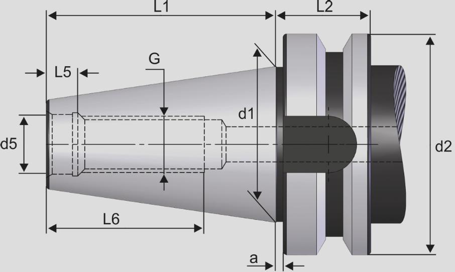
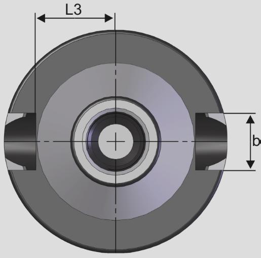
189
PORTAUTENSILI BT
Nome del prodotto Dimensioni (mm) / Dimensions (mm) Product name d1 G d5 d2 a L1 L2 L3 L5 L6 b BT 30 31,75 M12 M12,5 46 2 48,4 22 16,3 7 24 16,1 BT 40 44,45 M16 17 63 2 65,4 27 22,5 8,2 32 16,1 BT 50 69,85 M24 25 100 3 101,8 38 35,3 11 47 25,7
BILANCIATURA STANDARD G 6,3 15.000 giri/min STANDARD BALANCING G 6,3 15,000 RPM BT ADB BT AD Accessori per macchine utensili / Tooling systems
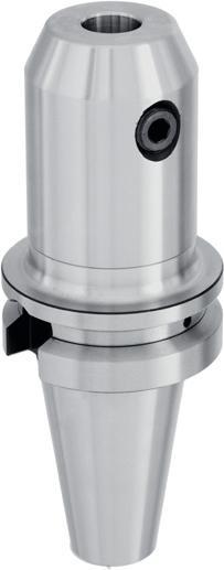
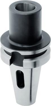
190 Accessori per macchine utensili / Tooling systems Portautensili Norma - BT (JIS 6339) Toolholders - BT (JIS 6339) 03
Reference Dimensione del cono Cone size Ø Interno We (mm) Internal Ø We (mm) Esterno Ø BD (mm) External Ø BD (mm) Lunghezza LPR (mm) Length LPR (mm) Codice Code BT40-W10X63-4MP 40 10 35 63 69 067 077 BT40-W12X63-4MP 40 12 42 63 69 067 085 BT40-W16X63-4MP 40 16 48 63 69 067 093 BT40-W20X63-4MP 40 20 52 63 69 067 107 BT40-W25X90-4MP 40 25 65 90 69 067 115 BT40-W32X100-4MP 40 32 72 100 69 067 123 BT50-W10X63-4MP 50 10 35 63 69 067 131 BT50-W12X80X4MP 50 12 42 80 69 067 158 BT50-W16X80-4MP 50 16 48 80 69 067 166 BT50-W20X80-4MP 50 20 52 80 69 067 174 BT50-W25X100-4MP 50 25 65 100 69 067 182 BT50-W32X105-4MP 50 32 72 105 69 067 190 BT50-W40X120-4MP 50 40 80 120 69 067 204 We LPR BD
Collegamento lato macchina: BT Tipo di refrigerazione AD/B Tolleranza: AT2 Bilanciamento: G 6,3 a 15.000 giri/min. Milling toolholder Weldon Machine-tools connection : BT Coolant type : AD/B Accuracy : AT2 Balancing : G 6,3 at 15000 RPM. Articolo Reference Dimensione del cono Cone size Tipo CM Type CM Lunghezza LPR (mm) Length LPR (mm) Esterno Ø BD (mm) External Ø BD (mm) Codice Code BT40-FORCM2X50-4MP 40 CM2 50 32 69 067 433 BT40-FORCM3X70-4MP 40 CM3 70 40 69 067 441 BT40-FORCM4X95-4MP 40 CM4 95 48 69 067 468 BT50-FORCM2X60-4MP 50 CM2 60 32 69 067 476 BT50-FORCM3X65-4MP 50 CM3 65 40 69 067 484 BT50-FORCM4X95-4MP 50 CM4 95 48 69 067 492 LPR BD Mandrino porta-punta Cono morse Collegamento lato macchina: BT Tipo di refrigerazione AD Tolleranza: AT2 Bilanciamento: G 6,3 a 15.000 giri/min. Adatto per punte cono Morse. Morse taper drills toolholder Machine-tools connection : BT Coolant type : AD Taper accuracy : AT2 Balancing : G 6,3 at 15000 RPM. Adapted for morse taper drills.
Articolo
Mandrino per porta-frese Weldon
Portautensili - BT (JIS 6339) Toolholders - BT (JIS 6339)
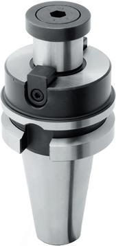
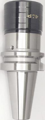
BD d
Mandrino di maschiatura con compensazione assiale
Collegamento lato macchina: BT
Grande compensazione assiale per recuperare la di erenza tra l'avanzamento della macchina e la rotazione del mandrino.
Gabbia a sfere per migliorare la sensibilità di compensazione.
Maschiatore per aumentare la pressione di innesto al fine di ottenere una profondità di maschiatura precisa entro ( 0,1 mm.
Tapping chuck with axial compensation
Machine-tools connection : BT
Large axial stroke to o�set the di�erence between the tap pitch and machine feed.
Ball retainer for a smooth axial compensation.
Device to increase the entry pressure, to obtain the controlled tapping depth ± 0,1 mm.
191 Accessori per macchine utensili / Tooling systems
Reference Dimensione del cono Cone size Ø Foro fresa D (mm) Bore of mill Ø D (mm) Ø Superficie di appoggio BD (mm) Support surface Ø BD (mm) Lunghezza LPR (mm) Length LPR (mm) Codice Code BT40-SURF16X45-4MP 40 16 38 45 69 067 212 BT40-SURF16X100-4MP 40 16 38 100 69 067 220 BT40-SURF22X45-4MP 40 22 48 45 69 067 239 BT40-SURF22X100-4MP 40 22 48 100 69 067 247 BT40-SURF27X45-4MP 40 27 58 45 69 067 255 BT40-SURF27X100-4MP 40 27 58 100 69 067 263 BT40-SURF32X56-4MP 40 32 63 56 69 067 271 BT40-SURF32X100-4MP 40 32 63 100 69 067 298 BT40-SURF40X50-4MP 40 40 80 50 69 067 301 BT40-SURF40X100-4MP 40 40 80 100 69 067 328 BT50-SURF16X50-4MP 50 16 38 50 69 067 336 BT50-SURF16X100-4MP 50 16 38 100 69 067 344 BT50-SURF22X55-4MP 50 22 48 55 69 067 352 BT50-SURF22X100-4MP 50 22 48 100 69 067 360 BT50-SURF27X55-4MP 50 27 58 55 69 067 379 BT50-SURF27X100-4MP 50 27 58 100 69 067 387 BT50-SURF32X55-4MP 50 32 78 55 69 067 395 BT50-SURF32X100-4MP 50 32 78 100 69 067 409 BT50-SURF40X55-4MP 50 40 88 55 69 067 417 BT50-SURF40X100-4MP 50 40 88 100 69 067 425 LPR BD Mandrino porta-frese con foro liscio Collegamento lato macchina: BT Tipo di refrigerazione AD/B Tolleranza: AT2 Bilanciamento: G
Shell mill Holder Machine-tools connection : BT Coolant type : AD/B Taper accuracy : AT2 Balancing : G 6,3 at 15000 RPM.
Articolo
6,3 a 15.000 giri/min.
Articolo Reference Dimensione del cono Cone size Ø Bussola d (mm) Collet Ø d (mm) Ø Esterno BD (mm) External Ø BD (mm) Lunghezza LPR (mm) Length LPR (mm) Codice Code BT40-TARCOMP19-4MP 40 19 38 68 69 067 786 BT40-TARCOMP31-4MP 40 31 55 93 69 067 794 BT50-TARCOMP19-4MP 50 19 38 80 69 067 808 BT50-TARCOMP31-4MP 50 31 55 102 69 067 816 LPR
Chiavi di serraggio P 213. Wrench P 213.
03
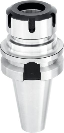
Mandrino a pinza ER - DIN6499
Collegamento lato macchina: BT
Tipo di refrigerazione AD/B
Tolleranza: AT2
Bilanciamento: G 6,3 a 15.000 giri/min.
Collet chuck for ER DIN6499
Machine-tools connection : BT
Coolant type : AD/B
Taper accuracy : AT2
Balancing : G 6,3 at 15000 RPM.
Dadi e chiavi di serraggio P 213. Clamping nut and wrench P 213.
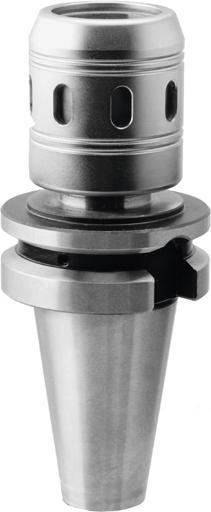
Mandrino a forte serraggio
Collegamento lato macchina: BT
Mandrino a forte serraggio per pinze cilindriche
Tipo di refrigerazione AD/B
Tolleranza: AT2
Bilanciamento: G 6,3 a 15.000 giri/min. Power milling chuck
192 Accessori per macchine utensili / Tooling systems Portautensili - BT (JIS 6339) Toolholders - BT (JIS 6339) 03 Articolo Reference Dimensione del cono Cone size Capacità Capacity Lunghezza LPR (mm) Length LPR (mm) Codice Code BT40-PPER16X70-4MP 40 ER16 (1 ÷ 10) 70 69 067 506 BT40-PPER16X100-4MP 40 ER16 (1 ÷ 10) 100 69 067 514 BT40-PPER16X160-4MP 40 ER16 (1 ÷ 10) 160 69 067 522 BT40-PPER25X70-4MP 40 ER25 (1 ÷ 16) 70 69 067 530 BT40-PPER25X100-4MP 40 ER25 (1 ÷ 16) 100 69 067 549 BT40-PPER25X160-4MP 40 ER25 (1 ÷ 16) 160 69 067 557 BT40-PPER32X70-4MP 40 ER32 (2 ÷ 20) 70 69 067 565 BT40-PPER32X100-4MP 40 ER32 (2 ÷ 20) 100 69 067 573 BT40-PPER32X160-4MP 40 ER32 (2 ÷ 20) 160 69 067 581 BT40-PPER40X70-4MP 40 ER40 (3 ÷ 26) 70 69 067 603 BT40-PPER40X100-4MP 40 ER40 (3 ÷ 26) 100 69 067 611 BT50-PPER32X80-4MP 50 ER32 (2 ÷ 20) 80 69 067 654 BT50-PPER32X160-4MP 50 ER32 (2 ÷ 20) 160 69 067 662 BT50-PPER40X80-4MP 50 ER40 (3 ÷ 26) 80 69 067 670 BT50-PPER40X160-4MP 50 ER40 (3 ÷ 26) 160 69 067 689 LPR
Articolo Reference Dimensione del cono Cone size Ø Interno D (mm) Internal Ø D (mm) Ø Esterno BD (mm) External Ø BD (mm) Lunghezza LPR (mm) Length LPR (mm) Pinze Collet Codice Code BT40-HP20X80-4MP 40 20 50 80 CYL20 - da Ø6 a/to Ø16 69 067 697 BT40-HP32X85-4MP 40 32 62 85 CYL32 - da Ø16 a/to Ø2569 067 700 BT50-HP20X100-4MP 50 20 50 100 CYL20 - da Ø6 a/to Ø16 69 067 719 BT50-HP32X100-4MP 50 32 62 100 CYL32 - da Ø16 a/to Ø2569 067 727 LPR D BD
Machine-tools
High
coolant
Taper accuracy
Balancing
G 6,3
RPM.
connection : BT
power clamping chuck for cylindrical sleeves
type : AD/B
: AT2
:
at 15000
Portautensili - BT (JIS 6339)
Toolholders - BT (JIS 6339)
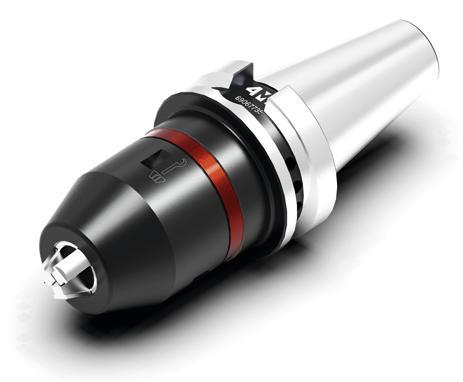
Mandrino di foratura di precisione integrale
Collegamento lato macchina: BT
Tipo di refrigerazione AD
Bilanciamento: G 6,3 a 15.000 giri/min
Eccentricità massima di 0,05 mm.
Sistema di bloccaggio laterale con chiave Torx (25).
Consente la rotazione a destra e a sinistra.
Per forare, fresare, alesare e maschiare.
Pressione massima del refrigerante: 50 bar.
Monobloc precision drill chuck
Machine-tool connection : BT
Coolant type : AD
Balancing : G 6,3 at 15000 RPM
Maximum total integrated run-out of 0,05 mm.
Lateral clamping system with Torx (25).
Clockwise and Counterclockwise machining possibility.
Drilling, milling, reaming and tapping possibilities.
Maximum coolant pressure : 50 bar.
193 Accessori per macchine utensili / Tooling systems
03
Reference Dimensione del cono Cone size Capacità (mm) Capacity (mm) Ø Esterno BD (mm) External Ø BD (mm) Lunghezza L1 (mm) Length L1 (mm) Lunghezza L2 (mm) Length L2 (mm) Codice Code BT40-MANDPERC1-16AUTO-4MP 40 1 - 16 50 95 104 69 067 735 BT50-MANDPERC1-16AUTO-4MP 50 1 - 16 50 106 116 69 067 751 L1 L2 BD
Articolo
Articolo Reference Attacco Toolholder Angolo °C Angle ° C Lunghezza totale L (mm) Total Length L (mm) Refrigerazione Coolant Lunghezza L1 (mm) Length L1 (mm) Diametro D (mm) Diameter D (mm) Diametro D1 (mm) Diameter D1 (mm) Filettatura F Threading F Codice Code CODOLO-BT40-45D-NON FORATO-4MP BT40 45 60 No / No 28 15 17 M16 69 071 244 CODOLO-BT40-45D-PERCEE-4MP BT40 45 60 Sì / Yes 28 15 17 M16 69 071 252 CODOLO-BT40-60D-NON FORATO-4MP BT40 60 60 No / No 28 15 17 M16 69 071 260 CODOLO-BT40-90D-NON FORATO-4MP BT40 90 60 No / No 28 15 17 M16 69 071 279 CODOLO-BT50-45D-NON FORATO-4MP BT50 45 85 No / No 35 23 25 M24 69 071 287 CODOLO-BT50-45D-FORATO-4MP BT50 45 85 Sì / Yes 35 23 25 M24 69 071 295 L L1 F D1 D C Codolo MAS 403 BT Per centri di lavoro Pull stud MAS 403 BT for machining centers Articolo Reference Attacco Toolholder Lunghezza LPR (mm) Total Length L (mm) Refrigerazione Coolant Lunghezza L1 (mm) Length L1 (mm) Diametro D (mm) Diameter D (mm) Diametro D1 (mm) Diameter D1 (mm) Filettatura F Threading F Collegamento macchina Machine-tool connection Codice Code TIRETTE-BT40-OTT SA40-4MP BT40 56 Sì / Yes 17.54 25 17 M16 SA40 (DIN 2080) 69 071 333 TIRETTE-BT50-OTT SA50-4MP BT50 65 Sì / Yes 14 39.6 25 M24 SA50 (DIN 2080) 69 071 341 D F D1 L1 L Codolo MAS 403 OTT/BT Per collegamento lato macchina DIN 2080. Da adattare su un mandrino BT per formare un mandrino DIN 2080. Pull stud MAS 403 OTT/BT For machine-tools connection DIN 2080 To be adapted on BT chuck to form a DIN 2080 chuck.
ISO AD+B (DIN 69871) - Dimensioni secondo norma
Dimensions according to standard
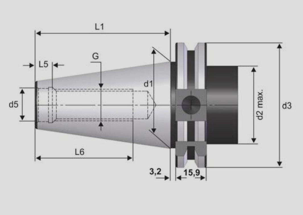
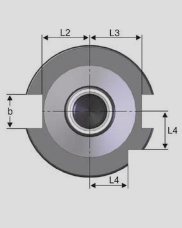
194 DIN 69 871 AD B DIN 69 871 AD Nome del prodotto Dimensioni (mm)/ Dimensions (mm) Product name d1 G d5 d2 d3 L1 L2 L3 L4 L5 L6 b SK 30 31,75 M12 13 45 50,00 47,80 16,4 19,0 15 5,5 24 16,1 SK 40 44,45 M16 17 50 63,55 68,40 22,8 25,0 18,5 8,2 32 16,1 SK 50 69,85 M24 25 80 97,50 101,75 35,5 37,7 30 11,5 47 25,7 PORTAUTENSILI DIN 69871
EQUILIBRATURA STANDARD G 6,3 15.000 giri/min STANDARD BALANCING G 6,3 15,000 RPM
DIN 69871 TOOLHOLDERS
Accessori per macchine utensili / Tooling systems
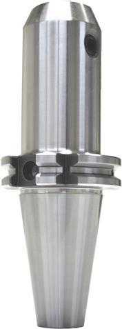
Mandrino per porta-frese
Weldon Collegamento lato macchina:
ISO (DIN 69871)
Tipo di refrigerazione AD/B
Tolleranza: AT2
Bilanciamento: G 6,3 a 15.000 giri/min.
Milling toolholder Weldon Machine-tools connection : SK (DIN 69871)
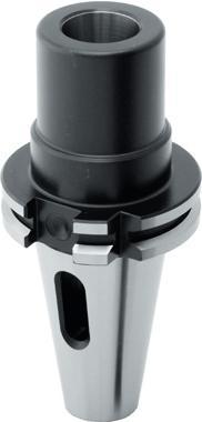
Mandrino porta-punta
Cono morse
Collegamento lato macchina:
ISO (DIN 69871)
Tipo di refrigerazione AD
Tolleranza: AT2
Bilanciamento: G 6,3 a 15.000 giri/min.
Adatto per punte cono Morse.
195 Accessori per macchine utensili / Tooling systems
Portautensili Norma ISO (DIN 69871)
03 Articolo Reference Dimensione del cono Cone size Ø Interno We (mm) Internal Ø We (mm) Ø Esterno. BD (mm) External Ø BD (mm) Lunghezza LPR (mm) Length LPR (mm) Codice Code ISO40-W10X50-4MP 40 10 35 50 69 067 824 ISO40-W12X50-4MP 40 12 42 50 69 067 832 ISO40-W16X63-4MP 40 16 48 63 69 067 840 ISO40-W20X63-4MP 40 20 52 63 69 067 859 ISO40-W25X100-4MP 40 25 65 100 69 067 867 ISO40-W32X100-4MP 40 32 72 100 69 067 875 ISO50-W10X63-4MP 50 10 35 63 69 067 883 ISO50-W12X63-4MP 50 12 42 63 69 067 891 ISO50-W16X63-4MP 50 16 48 63 69 067 905 ISO50-W20X63-4MP 50 20 52 63 69 067 913 ISO50-W25X80-4MP 50 25 65 80 69 067 921 ISO50-W32X100-4MP 50 32 72 100 69 067 948 ISO50-W40X112-4MP 50 40 80 112 69 067 956 LPR
Toolholders - SK (DIN 69871)
BD We
Balancing
G 6,3
Articolo Reference Dimensione del cono Cone size Tipo CM Type CM Lunghezza LPR (mm) Length LPR (mm) Ø Fuori. DB (mm) External Ø BD (mm) Codice Code ISO40-FORCM2X50-4MP 40 CM2 50 32 69 068 189 ISO40-FORCM3X70-4MP 40 CM3 70 40 69 068 197 ISO40-FORCM4X95-4MP 40 CM4 95 48 69 068 200 ISO50-FORCM2X60-4MP 50 CM2 60 32 69 068 219 ISO50-FORCM3X65-4MP 50 CM3 65 40 69 068 227 ISO50-FORCM4X95-4MP 50 CM4 95 48 69 068 235 CM LPR BD
Coolant type : AD/B Accuracy : AT2
:
at 15000 RPM.
Morse taper drills toolholder Machine-tools connection : SK (DIN 69871) Coolant type : AD Taper accuracy : AT2 Balancing : G 6,3 at 15000 RPM. Adapted for morse taper drills.
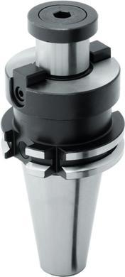
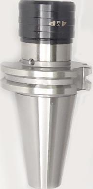
Mandrino porta-frese con foro liscio
Collegamento lato macchina:
ISO (DIN 69871)
Tipo di refrigerazione AD/B
Tolleranza: AT2
Bilanciamento: G 6,3 a 15.000 giri/min.
Shell mill toolholder Machine-tools connection : SK (DIN 69871) Coolant type : AD/B
Mandrino di maschiatura con compensazione assiale
Collegamento lato macchina: ISO (DIN 69871). Grande compensazione assiale per recuperare la di erenza tra l'avanzamento della macchina e la rotazione del mandrino. Gabbia a sfere per migliorare la sensibilità di compensazione. Maschiatore per aumentare la pressione di innesto al fine di ottenere una profondità di maschiatura precisa entro ( 0,1 mm.
Tapping chuck with axial compensation
Machine-tools connection : SK (DIN 69871).
Large axial stroke to o�set the di�erence between the tap pitch and machine feed. Ball retainer for a smooth axial compensation. Device to increase the entry pressure, to obtain the controlled tapping depth ± 0,1 mm.
196 Accessori per macchine utensili / Tooling systems
Norma ISO (DIN 69871) Toolholders - SK (DIN 69871) 03 Articolo Reference Dimensione del cono Cone size Ø Foro fresa D (mm) Bore of mill Ø D (mm) Ø Superficie di appoggio BD (mm) Support surface Ø BD (mm) Lunghezza LPR (mm) Length LPR (mm) Codice Code ISO40-SURF16X45-4MP 40 16 38 45 69 067 964 ISO40-SURF16X100-4MP 40 16 38 100 69 067 972 ISO40-SURF22X45-4MP 40 22 48 45 69 067 980 ISO40-SURF22X100-4MP 40 22 48 100 69 067 999 ISO40-SURF27X45-4MP 40 27 58 45 69 068 006 ISO40-SURF27X100-4MP 40 27 58 100 69 068 014 ISO40-SURF32X55-4MP 40 32 78 55 69 068 022 ISO40-SURF32X100-4MP 40 32 78 100 69 068 030 ISO40-SURF40X60-4MP 40 40 88 60 69 068 049 ISO40-SURF40X100-4MP 40 40 88 100 69 068 057 ISO50-SURF16X45-4MP 50 16 38 45 69 068 065 ISO50-SURF16X100-4MP 50 16 38 100 69 068 073 ISO50-SURF22X45-4MP 50 22 48 45 69 068 081 ISO50-SURF22X100-4MP 50 22 48 100 69 068 103 ISO50-SURF27X45-4MP 50 27 58 45 69 068 111 ISO50-SURF27X100-4MP 50 27 58 100 69 068 138 ISO50-SURF32X45-4MP 50 32 78 45 69 068 146 ISO50-SURF32X100-4MP 50 32 78 100 69 068 154 ISO50-SURF40X50-4MP 50 40 88 50 69 068 162 ISO50-SURF40X100-4MP 50 40 88 100 69 068 170 LPR D BD
Portautensili
Taper
Balancing
G 6,3
RPM. Articolo Reference Dimensione del cono Cone size Ø Bussola d (mm) Collet Ø d (mm) Ø Esterno BD (mm) External Ø BD (mm) Lunghezza LPR (mm) Length LPR (mm) Codice Code ISO40-TARCOMP19-4MP 40 19 38 60 69 068 472 ISO40-TARCOMP31-4MP 40 31 55 100 69 068 480 ISO50-TARCOMP19-4MP 50 19 38 62 69 068 499 ISO50-TARCOMP31-4MP 50 31 55 83 69 068 502 LPR BD d
accuracy : AT2
:
at 15000
Chiavi di serraggio P 213. Wrench P 213.
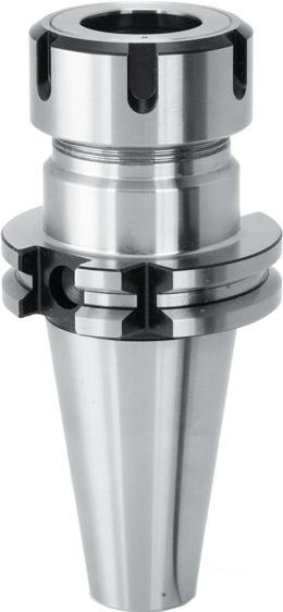
Mandrino a pinza
ER - DIN 6499
Collegamento lato macchina:
ISO (DIN 69871)
Tipo di refrigerazione AD
Tolleranza: AT2
Bilanciamento: G 6,3 a 15.000 giri/min.
Dadi e chiavi di serraggio P 213. Clamping nut and wrench P 213.
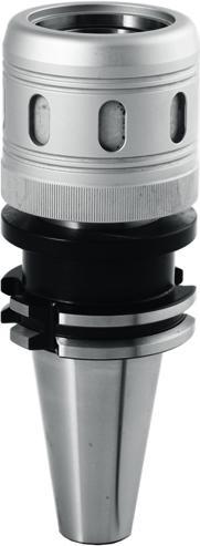
Mandrino a forte serraggio
Collegamento lato macchina: ISO (DIN 69871)
Mandrino a forte serraggio per pinze cilindriche
Tipo di refrigerazione AD/B
Tolleranza: AT2
Bilanciamento: G 6,3 a 15.000 giri/min.
Collet chuck for ER DIN 6499
Machine-tools connection : SK (DIN 69871)
Coolant type : AD
accuracy : AT2 Balancing : G 6,3 at 15000 RPM.
197 Accessori per macchine utensili / Tooling systems
SK
03 Articolo Reference Dimensione del cono Cone size Capacità Capacity Lunghezza LPR (mm) Length LPR (mm) Codice Code ISO40-PPER16X70-4MP 40 ER16 (1 ÷ 10) 70 69 068 243 ISO40-PPER16X100-4MP 40 ER16 (1 ÷ 10) 100 69 068 251 ISO40-PPER16X160-4MP 40 ER16 (1 ÷ 10) 160 69 068 278 ISO40-PPER25X70-4MP 40 ER25 (1 ÷ 16) 70 69 068 286 ISO40-PPER25X100-4MP 40 ER25 (1 ÷ 16) 100 69 068 294 ISO40-PPER25X160-4MP 40 ER25 (1 ÷ 16) 160 69 068 308 ISO40-PPER32X70-4MP 40 ER32 (2 ÷ 20) 70 69 068 316 ISO40-PPER32X100-4MP 40 ER32 (2 ÷ 20) 100 69 068 324 ISO40-PPER32X160-4MP 40 ER32 (2 ÷ 20) 160 69 068 332 ISO40-PPER40X70-4MP 40 ER40 (3 ÷ 26) 70 69 068 340 ISO40-PPER40X100-4MP 40 ER40 (3 ÷ 26) 100 69 068 359 ISO50-PPER32X80-4MP 50 ER32 (2 ÷ 20) 80 69 068 383 ISO50-PPER32X160-4MP 50 ER32 (2 ÷ 20) 160 69 068 391 ISO50-PPER40X80-4MP 50 ER40 (3 ÷ 26) 80 69 068 405 ISO50-PPER40X160-4MP 50 ER40 (3 ÷ 26) 160 69 068 413 LPR
Portautensili Norma ISO (DIN 69871) Toolholders -
(DIN 69871)
Articolo Reference Dimensione del cono Cone size Ø Interno D (mm) Internal Ø D (mm) Ø Esterno BD (mm) External Ø BD (mm) Lunghezza LPR (mm) Length LPR (mm) Pinze Collet Codice Code ISO40-HP20X80-4MP 40 20 50 80 CYL20 - da Ø6 a/to Ø16 69 068 510 ISO40-HP32X85-4MP 40 32 62 85 CYL32 - da Ø16 a/to Ø2569 068 529 ISO50-HP20X100-4MP 50 20 50 100 CYL20 - da Ø6 a/to Ø16 69 068 537 ISO50-HP32X100-4MP 50 32 62 100 CYL32 - da Ø16 a/to Ø2569 068 545
Taper
Balancing
Power milling chuck Machine-tools connection : SK (DIN 69871) High power clamping chuck for cylindrical sleeves Coolant type : AD/B Taper accuracy : AT2
: G 6,3 at 15000 RPM.
BD D LPR
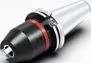
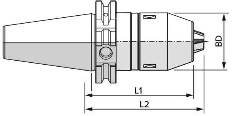
Mandrino di foratura di precisione integrale
Collegamento lato macchina: ISO (DIN 69871).
Tipo di refrigerazione AD.
Bilanciamento: G 6,3 15000 tr/mn.
Eccentricità massima integrata di 0,05 mm.
Sistema di bloccaggio laterale con chiave Torx (25).
Consente la rotazione a destra e a sinistra.
Per forare, fresare, alesare e maschiare.
Pressione massima del refrigerante: 50 bar.
Viene fornito con manuale di istruzioni.
Monobloc precision drill chuck
Machine-tool connection :
SK (DIN 69871).
Coolant type : AD.
Balancing : G 6,3 at 15000 RPM.
Maximum total integrated run-out of 0,05 mm.
Lateral clamping system with Torx (25).
Clockwise and Counterclockwise machining possibility.
Drilling, mlling, reaming and tapping possibilities.
Maximum coolant pressure : 50 bar. Furnished with instructions for use manual.
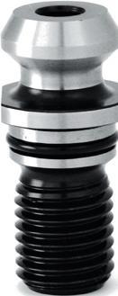
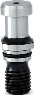
198 Accessori per macchine utensili / Tooling systems
Norma ISO (DIN 69871) Toolholders - ISO (DIN 69871) 03 Articolo Reference Dimensione del cono Cone size Capacità (mm) Capacity (mm) Ø Esterno BD (mm) External Ø BD (mm) Lunghezza L1 (mm) Length L1 (mm) Lunghezza L2 (mm) Length L2 (mm) Codice Code ISO40-MANDPERC1-16AUTO-4MP 40 1 - 16 50 80 90 69 068 421 ISO50-MANDPERC1-16AUTO-4MP 50 1 - 16 50 80 90 69 068 456
Portautensili
Articolo Reference Attacco Toolholder Angolo °C Angle °C Lunghezza totale L (mm) Total Length L (mm) Refrigerazione Coolant Lunghezza L1 (mm) Length L1 (mm) Diametro D (mm) Diameter D (mm) Diametro D1 (mm) Diameter D1 (mm) Filettatura F Threading F Codice Code TIRETTE-ISO40DIN7388245D-P-4MP ISO 40 45 44.5 Sì / Yes 11.15 18.95 17 M16 69 071 309 C D F D1 L L1 Codolo ISO 7388/2 B Per centri di lavoro Pull stud ISO 7388/2 B Suitable for machining centers Articolo Reference Attacco Toolholder Angolo °C Angle °C Lunghezza totale L (mm) Total Length L (mm) Refrigerazione Coolant Lunghezza L1 (mm) Length L1 (mm) Diametro D (mm) Diameter D (mm) Diametro D1 (mm) Diameter D1 (mm) Filettatura F Threading F Codice Code TIRETTE-ISO40DIN 69872-P-4MP ISO 40 15 54 Sì / Yes 20 19 17 M16 69 071 317 TIRETTE-ISO50DIN 69872B-P-4MP ISO 50 15 74 Sì / Yes 25 28 25 M24 39 071 325 C L L1 D F D1 Codolo DIN 69872 Per centri di lavoro Pull stud DIN 69872 Suitable for machining centers
PORTAUTENSILI HSK-A HSK-A TOOLHOLDERS
HSK-A (DIN 69893-1) - Dimensioni secondo norma
Dimensions according to standard AAccessori per macchine utensili / Tooling systems
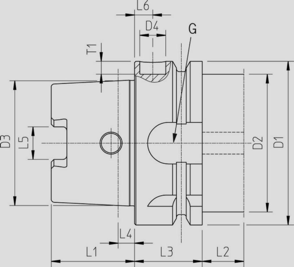
199 Nome del prodotto Dimensioni (mm) / Dimensions (mm) Product name D1 D2 D3 D4 L1 L2 L3 L4 L5 L6 G T1 max. min. HSK-A 32 32 26 24,007 10 16 15 20 3,2 7,05 7 M10 x 1 5,4 HSK-A 40 40 34 30,007 10 20 15 20 4 8,05 7 M12 x 1 5,3 HSK-A 50 50 42 38,009 10 25 16 26 5 10,54 7 M16 x 1 5,2 HSK-A 63 63 53 48,010 10 32 16 26 6,3 12,54 7 M18 x 1 5 HSK-A 80 80 67 60,012 10 40 16 26 8 16,04 7 M20 x 1,5 5 HSK-A 100 100 85 75,013 10 50 16 29 10 20,02 7 M24 x 1,5 4,9 HSK-A 125 125 111 95,016 10 63 16 29 12,5 25,02 7 M30 x 1,5 4,8
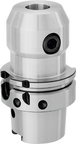
Mandrino per porta-frese
Weldon
Collegamento lato macchina: HSK forma A (DIN 69893-1)
Tolleranza: AT2
Bilanciamento: G 6,3 a 15.000 giri/min. Raccordo di refrigerazione e chiave non forniti.
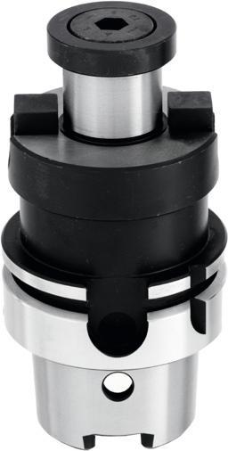
Accessori per macchine utensili / Tooling systems
- HSK-A (DIN 69893-1) Toolholders - HSK-A (DIN 69893-1) 03 Articolo Reference Dimensione del cono Cone size Ø Interno We (mm) Internal Ø We (mm) Ø Esterno. BD (mm) Ø Exter. BD (mm) Lunghezza LPR (mm) Length LPR (mm) Codice Code HSK63A-W10X65-4MP 63 10 35 65 69 068 553 HSK63A-W12X80-4MP 63 12 42 80 69 068 561 HSK63A-W16X80-4MP 63 16 48 80 69 068 588 HSK63A-W20X80-4MP 63 20 52 80 69 068 596 HSK63A-W25X110-4MP 63 25 65 110 69 068 618 HSK63A-W32X110-4MP 63 32 72 110 69 068 626 LPR
We
Portautensili
BD
Milling toolholder Weldon
connection
HSK FORM A (DIN 69893-1) Taper accuracy : AT2 Balancing : G 6,3 at 15000 RPM. Cooling tube & wrench not included. Articolo Reference Dimensione del cono Cone size Ø Foro fresa D (mm) Bore of mill Ø D (mm) Ø Superficie di appoggio BD (mm) Support surface Ø BD (mm) Lunghezza LPR (mm) Length LPR (mm) Codice Code HSK63A-SURF16X50-4MP 63 16 38 50 69 068 634 HSK63A-SURF22X50-4MP 63 22 48 50 69 068 642 HSK63A-SURF27X60-4MP 63 27 58 60 69 068 650 HSK63A-SURF32X60-4MP 63 32 78 60 69 068 669 HSK63A-SURF40X60-4MP 63 40 88 60 69 068 677 LPR D BD Mandrino porta-frese con foro liscio Collegamento lato macchina: HSK forma A (DIN 69893-1) Tolleranza: AT2 Bilanciamento: G 6.3 a 18000 giri/min. Raccordo di refrigerazione e chiave non forniti. Face mill toolholder Machine-tools connection : HSK FORM A (DIN 69893-1) Taper accuracy : AT2 Balancing : G 6,3 at 18000 RPM. Cooling tube & wrench not included. Chiavi di serraggio P 213. Wrench P 213. 200
Machine-tools
:
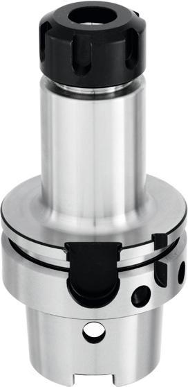
213.
213.
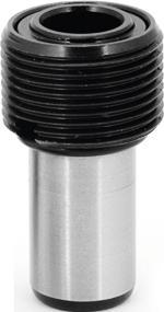
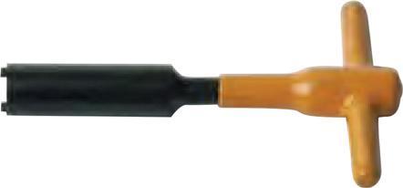
Mandrino a pinza ER - DIN6499
Collegamento lato macchina: HSK forma A(DIN 69893-1)
Tolleranza: AT2
Bilanciamento: G 6,3 a 15.000 giri/min. Raccordo di refrigerazione e chiave non forniti.
Collet chuck for ER DIN 6499
Machine-tools connection : HSK FORM A (DIN 69893-1)
Taper accuracy : AT2
Balancing : G 6,3 at 18000 RPM.
Cooling tube & wrench not included.
Accessori per macchine utensili / Tooling systems
03 Articolo Reference Dimensione del cono Cone size Capacità Capacity Lunghezza LPR (mm) Length LPR (mm) Codice Code HSK63A-PPER16X100-4MP 63 ER16 (1 ÷ 10) 100 69 068 685 HSK63A-PPER16X160-4MP 63 ER16 (1 ÷ 10) 160 69 068 693 HSK63A-PPER25X100-4MP 63 ER25 (1 ÷ 16) 100 69 068 707 HSK63A-PPER25X160-4MP 63 ER25 (1 ÷ 16) 160 69 068 715 HSK63A-PPER32X100-4MP 63 ER32 (2 ÷ 20) 100 69 068 723 HSK63A-PPER32X160-4MP 63 ER32 (2 ÷ 20) 160 69 068 731 LPR
Porte-outils Norme HSK-A (DIN 69893-1) Toolholders - HSK-A (DIN 69893-1)
Reference Codice Code RACCORDHSK63-4MP 69 071 465 Raccordo HSK63 Raccord HSK63 HSK cooling tube Articolo Reference Codice Code CLERAC-HSK63-4MP 71 013 375 Chiave per raccordo HSK63 Wrench
cooling tube 201
Dadi e chiavi di serraggio P
Clamping nut and wrench P
Articolo
for HSK
PORTAUTENSILI
TOOLHOLDERS
Portautensili cilindrici e coni morse
Straight shank and morse tappers toolholders
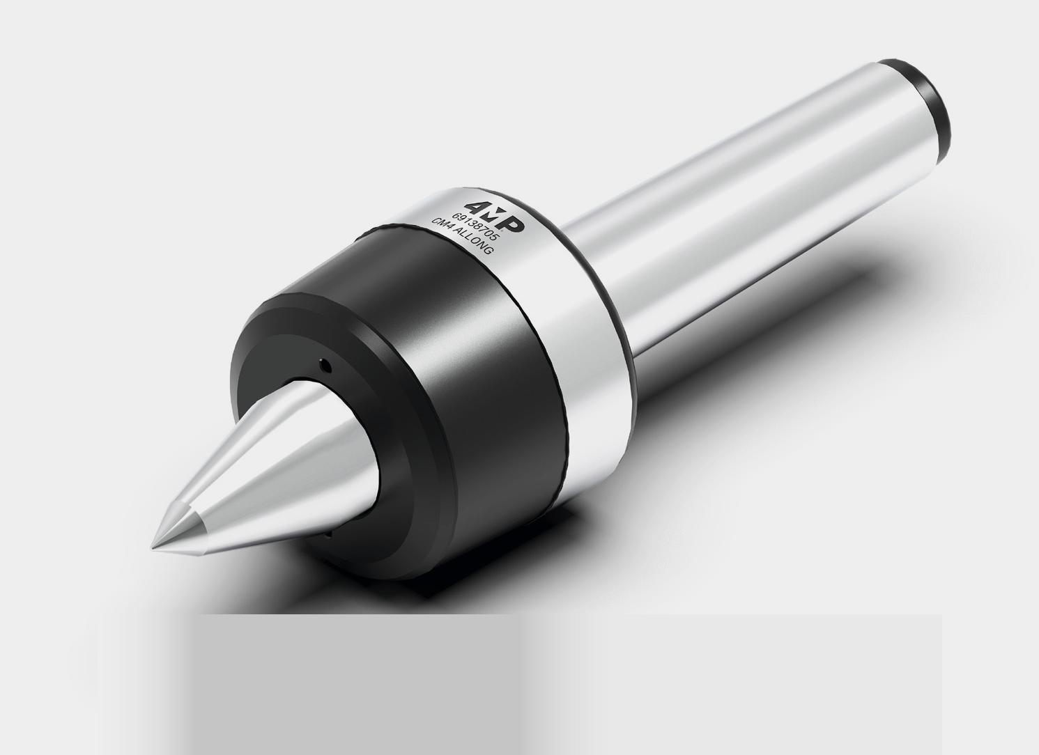
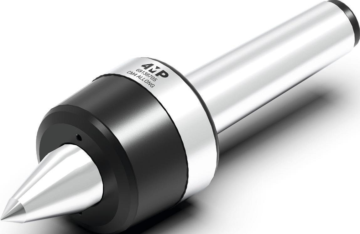


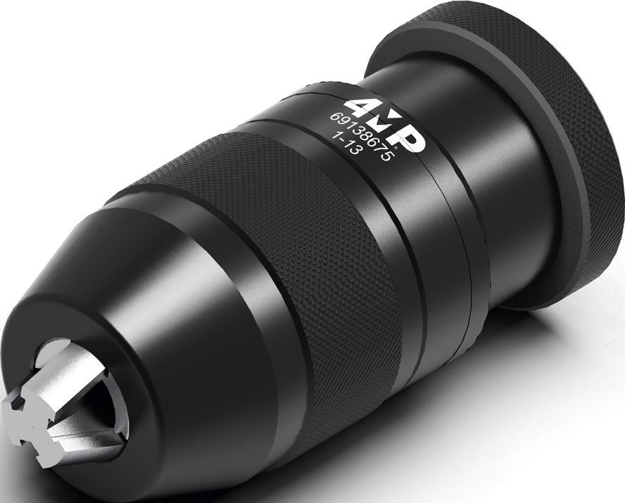

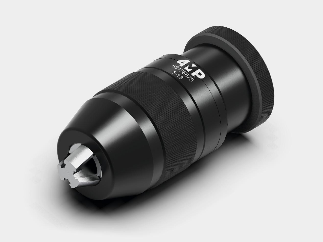
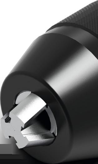
202 Accessori per macchine utensili/ Tooling systems
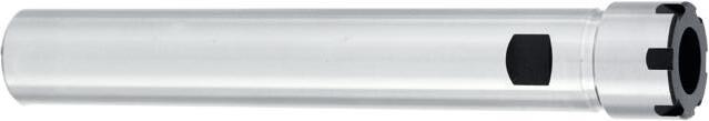
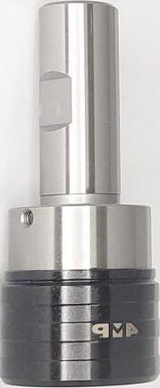
Mandrino di maschiatura con compensazione assiale Collegamento lato macchina: CilindricoDIN 1835 B+T. Grande compensazione assiale per recuperare la di erenza tra l'avanzamento della macchina e la rotazione del mandrino.
Gabbia a sfere per migliorare la sensibilità di compensazione. Maschiatore per aumentare la pressione di innesto al fine di ottenere una profondità di maschiatura precisa entro ( 0,1 mm.
Tapping chuck with axial compensation
Machine-tools connection : Cylindrical DIN 1835 B+E. Large axial stroke to o�set the di�erence between the tap pitch and machine feed. Ball retainer for a smooth axial compensation. Device to increase the entry pressure, to obtain the controlled tapping depth ± 0,1 mm.
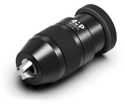
A Ø Mandrino di foratura autoserrante Mandrino per uso industriale. Bloccaggio automatico per un cambio utensile e ciente e rapido. Il meccanismo di autoserraggio aumenta automaticamente la forza di bloccaggio e previene l'allentamento dell'utensile durante il funzionamento. Rotazione in senso orario.
Keyless Drill Chucks
Drill chuck for industrial use. Automatic fitting for e�cient, fast change of tools. Self-tightening mechanism automatically increases the grip in proportion to the increase in torque during the drilling and avoids the tool slipping in clockwise rotation.
Accessori per macchine utensili / Tooling systems
cilindrici Straight shank toolholders 03 Articolo Reference Capacità Capacity Ø BD (mm) Ø BD (mm) Ø d1 (mm) Ø d1 (mm) Lunghezza L (mm) Length L (mm) Lunghezza LPR (mm) Length LPR (mm) Tipo di ghiera Clamping nuts type Codice Code RAL-ER11MD12X100-4MP ER11 (1 ÷ 7) 16 12 100 26 Mini 69 068 758 RAL-ER11MD16X160-4MP ER11 (1 ÷ 7) 16 16 160 19 Mini 69 068 766 RAL-ER16MD16X100-4MP ER16 (1 ÷ 10) 22 16 100 38 Mini 69 068 774 RAL-ER16MD20X160-4MP ER16 (1 ÷ 10) 22 20 160 31 Mini 69 068 782 RAL-ER20MD20X160-4MP ER20 (1 ÷ 13) 28 20 160 36 Mini 69 068 790 RAL-ER25MD25X130-4MP ER25 (1 ÷ 16) 35 25 130 40 Mini 69 068 804 PPINCECYL-ER32D32X70-4MP ER32 (2 ÷ 20)50 32 70 48 Standard 69 068 812 PPINCECYL-ER32D40X70-4MP ER32 (2 ÷ 20)50 40 70 33 Standard 69 068 820 L LPR d1 BD Prolunga porta-pinza ER - DIN 6499 Straight shank collet chuck for ER DIN 6499
Portautensili
Articolo Reference Attacco A (mm) Shank A (mm) Ø Bussola d (mm) Collet Ø d (mm) Ø Esterno BD (mm) External Ø BD (mm) Lunghezza LPR (mm) Length LPR (mm) Lunghezza L (mm) Length L (mm) Codice Code M3M12D20X50X19-4MP 20 19 38 41 50 69 068 839 M6M20D32X61X31-4MP 32 31 55 63 61 69 068 847 A LPR L d BD
Dadi e chiavi di serraggio P 213. Clamping nut and wrench P 213.
Articolo Reference Capacità Capacity Attacco A (mm) Shank A (mm) Ø Esterno (mm) External Ø (mm) Codice Code MAND.PERC1-13/B16 1 - 13 B16 47 69 138 675 MAND.PERC3-16/B16 3 - 16 B16 52 69 138 683
Set di gri e di ricambio per mandrino di foratura 1-13 e 3-16 Codice 69 140 491 Set of jaws for drill chuck capacity 1-13 and 3-16 Code 69 140 491 203
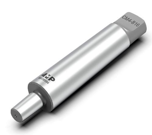
Riduzione per mandrino di foratura
La riduzione è un elemento intermedio tra il mandrino di foratura e il mandrino della macchina.
Le riduzioni 4MP sono completamente temprate e presentano una rettifica di precisione fine che garantisce un fissaggio con tolleranze ristrette e la massima concentricità.
Arbor for drill chuck
The arbor is an intermediary element between the drill chuck and the spindle of the machine. 4MP arbors are totally hardened and precision ground, ensuring a close fit and maximum concentricity.
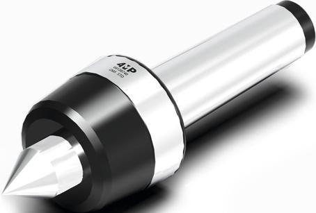
Contropunta rotante di precisione
Per il bloccaggio preciso dei pezzi su torni convenzionali e CNC. Le contropunte 4MP hanno una concentricità ottimale: per cono morse 4, concentricità di 0,003 mm e per cono morse 5, concentricità di 0,004 mm.
Rettifica di precisione e completamente temprata.
Modello C: Per un'ampia gamma di lavori di tornitura.
Revolving lathe centers
For counter-clamping workpieces in conventional or CNC turning machines. 4MP revolving lathe centres are of high precision, with a maximum run-out of 0,003 mm for Morse tapers no. 4 and 0,004 mm for Morse taper no. 5. Fully hardened and precision ground. Model C : For a wide range of general turning work.
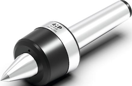
Contropunta rotante di precisione
Per il bloccaggio preciso dei pezzi su torni convenzionali e CNC.
Le contropunte 4MP hanno una concentricità ottimale: per cono morse 4, concentricità di 0,003 mm e per cono morse 5, concentricità di 0,004 mm.
Rettifica di precisione e completamente temprata.
Modello N: Aumenta l’ingombro dell’utensile e migliora la visibilità dell'utente per la tornitura di piccoli pezzi o la lavorazione in prossimità delle estremità dei pezzi.
Revolving lathe centers
For accurate work holding in conventional or CNC lathes.
4MP revolving lathe centres are of high precision, with a maximum run-out of 0,003 mm for Morse tapers no. 4 and 0,004 mm for Morse taper no. 5. Fully hardened and precision ground.
Model N : Increases tool clearance and operator visibility for work on small parts or machining close to workpiece end.
204 Accessori per macchine utensili / Tooling systems Portautensili cono morse Morse tapper toolholders 03 Articolo Reference Attacco Shank Collegamento Connection Codice Code RIDUZIONE-CM2/B16 CM2 B16 69 138 578 RIDUZIONE-CM3/B16 CM3 B16 69 138 586 RIDUZIONE-CM4/B16 CM4 B16 69 138 594
Articolo Reference Attacco Shank Ø d1 (mm) Ø d2 (mm) Ø d3 (mm) Lunghezza L1 (mm) Length L1 (mm) Lunghezza L2 (mm) Length L2 (mm) Lunghezza L3 (mm) Length L3 (mm) Codice Code PUNTA-GIRO-CM4-C CM4 30 63 - 35 52 196 69 138 721 PUNTA-GIRO-CM5-C CM5 33 85 - 48 64 250 69 138 748 60° d1 d2 L2 L1 L3
Articolo Reference Attacco Shank Ø d1 (mm) Ø d2 (mm) Ø d3 (mm) Lunghezza L1 (mm) Length L1 (mm) Lunghezza L2 (mm) Length L2 (mm) Lunghezza L3 (mm) Length L3 (mm) Codice Code PUNTA-GIRO-AL-CM4-N CM4 30 63 11 46 52 207 69 138 705 PUNTA-GIRO-AL-CM5-N CM5 33 85 18 64 64 266 69 138 713 60° d1 d3 d2 L1 L2 L3
BUSSOLE, PINZE E ACCESSORI SLEEVES, COLLETS AND ACCESSORIES


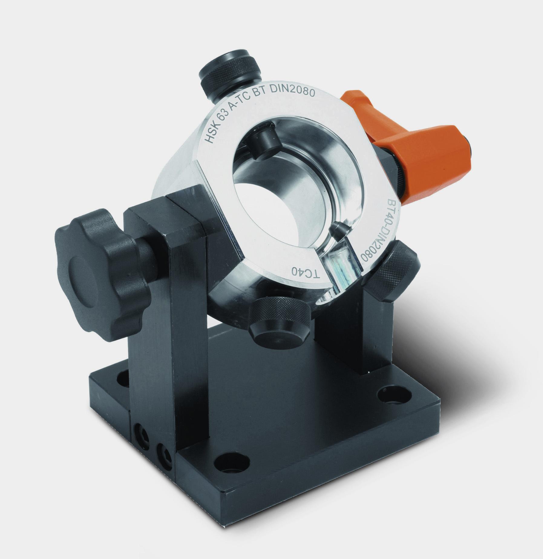


205
Accessori per macchine utensili / Tooling systems
Bussola di maschiatura con frizione
Bussola di maschiatura a cambio rapido con frizione regolabile. Prodotta con materiali di qualità che garantiscono una lunga durata. Le bussole sono regolate con una coppia adatta alla maschiatura su acciaio e possono essere regolate in base al materiale da lavorare, se necessario.
Bush for tapping with clutch
Quick change bush for tapping with clutch.
Built out of the highest quality steel therefore a longer tool life is guaranteed.
Tap adapters are set with a torque for tapping steel, they can be re set for other materials tapping.
Accessori per macchine utensili / Tooling systems Bussole, pinze e accessori Sleeves, collets and accessories 03 Articolo Reference Ø Bussola (mm) Ø Bush (mm) Per maschio For tap Ø Gambo del maschio (mm) Ø Shank tap (mm) Quadro Shank square Norma Norm Codice Code DOU19-M3DIN371AFRICT-4MP 19 M3 3,5 2,7 371 69 068 863 DOU19-M4DIN371AFRICT-4MP 19 M4 4,5 3,4 371 69 068 871 DOU19-M5DIN371AFRICT-4MP 19 M5 6 4,9 371 69 068 898 DOU19-M6DIN371AFRICT-4MP 19 M6 6 4,9 371 69 068 901 DOU19-M8DIN371AFRICT-4MP 19 M8 8 6,2 371 69 068 928 DOU19-M10DIN371AFRICT-4MP 19 M10 10 8 371 69 068 855 DOU19-M10DIN376AFRICT-4MP 19 M10 7 5,5 376 69 068 936 DOU19-M12DIN376AFRICT-4MP 19 M12 9 7 376 69 068 944 DOU19-M14DIN376AFRICT-4MP 19 M14 11 9 376 69 068 952 DOU31-M6DIN371AFRICT-4MP 31 M6 6 4,9 371 69 068 987 DOU31-M8DIN371AFRICT-4MP 31 M8 8 6,2 371 69 068 995 DOU31-M10DIN371AFRICT-4MP 31 M10 10 8 371 69 068 960 DOU31-M10DIN376AFRICT-4MP 31 M10 7 5,5 376 69 069 002 DOU31-M12DIN376AFRICT-4MP 31 M12 9 7 376 69 069 010 DOU31-M14DIN376AFRICT-4MP 31 M14 11 9 376 69 069 029 DOU31-M16DIN376AFRICT-4MP 31 M16 12 9 376 69 069 037 DOU31-M18DIN376AFRICT-4MP 31 M18 14 11 376 69 069 045 DOU31-M20DIN376AFRICT-4MP 31 M20 16 12 376 69 069 053 DOU31-M24DIN376AFRICT-4MP 31 M24 18 14,5 376 69 069 061
Articolo Reference Ø Esterno D1 (mm) External Ø D1 (mm) Ø Interno D2 (mm) Internal Ø D2 (mm) Codice Code PINZA-CYL20/6-4MP 20 6 69 071 384 PINZA-CYL20/8-4MP 20 8 69 071 392 PINZA-CYL20/10-4MP 20 10 69 071 406 PINZA-CYL20/12-4MP 20 12 69 071 414 PINZA-CYL20/16-4MP 20 16 69 071 422 PINZA-CYL32/16-4MP 32 16 69 071 430 PINZA-CYL32/20-4MP 32 20 69 071 449 PINZA-CYL32/25-4MP 32 25 69 071 457
cilindrica
Pinza
cilindrica per mandrino a forte serraggio Straight collet Straight collet for power milling chuck 206
Pinza
PRECISIONE DI RUNOUT
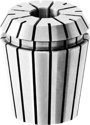
Pinza standard ER11 (DIN 6499)
collet (DIN 6499)
Realizzato in acciaio per molla.
Rettifica interna ed esterna.
Rugosità inferiore a Rz 2,5..
Capacità ER11: da 1 a 8 mm.
Capacità ER16: da 1 a 12 mm Campo di serraggio: 0,5 mm. Precisione di runout: 0,015 mm.
Pinza standard ER16 (DIN 6499)
ER16 collet (DIN 6499)
Manufactured in spring steel.
Grounded both externally and internally.
Grade of roughness lower than Rz 2,5. ER11 Capacity : 1 to 8 mm.
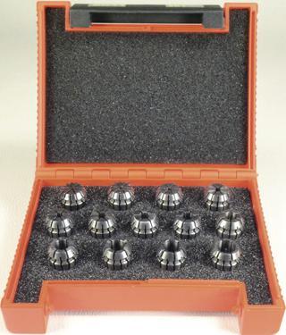
Accessori per macchine utensili / Tooling systems Bussole, pinze e accessori Sleeves, collets and accessories 03 Articolo Reference Ø Pinza (mm) Collet Ø (mm) Codice Code PINZA-ER11D1-0.5-4MP 1-0,5 69 069 088 PINZA-ER11D1.5-1-4MP 1,5-1 69 069 096 PINZA-ER11D2-1.5-4MP 2-1,5 69 069 118 PINZA-ER11D2.5-2-4MP 2,5-2 69 069 126 PINZA-ER11D3-2.5-4MP 3-2,5 69 069 134 PINZA-ER11D3,5-3-4MP 3,5-3 69 069 142 PINZA-ER11D4-3.5-4MP 4-3,5 69 069 150 PINZA-ER11D4,5-4-4MP 4,5-4 69 069 169 PINZA-ER11D5-4.5-4MP 5-4,5 69 069 177 PINZA-ER11D5,5-5-4MP 5,5-5 69 069 185 PINZA-ER11D6-5.5-4MP 6-5,5 69 069 193 PINZA-ER11D6,5-6-4MP 6,5-6 69 069 207 PINZA-ER11D7-6,5-4MP 7-6,5 69 069 215 PINZA-ER11D8-7,5-4MP 8-7,5 69 069 223
ER11
ER16 Capacity
Clamping range
Concentricity precision
Ø Pinza (mm) Collet Ø (mm) Codice Code PINZA-ER16D1-0,5-4MP 1-0,5 69 069 231 PINZA-ER16D2-1-4MP 2-1 69 069 258 PINZA-ER16D3-2-4MP 3-2 69 069 266 PINZA-ER16D4-3-4MP 4-3 69 069 274 PINZA-ER16D5-4-4MP 5-4 69 069 282 PINZA-ER16D6-5-4MP 6-5 69 069 290 PINZA-ER16D7-6-4MP 7-6 69 069 304 PINZA-ER16D8-7-4MP 8-7 69 069 312 PINZA-ER16D9-8-4MP 9-8 69 069 320 PINZA-ER16D10-9-4MP 10-9 69 069 339 PINZA-ER16D11-10-4MP 11-10 69 069 347 PINZA-ER16D12-11-4MP 12-11 69 069 355 Ø B ß L Ø D
: 1 to 12 mm
: 0,5 mm.
: 0,015 mm. Articolo Reference
CONCENTRICITY PRECISION TIPO TYPE ØD GAMMA DI SERRAGGIO/ CLAMPING RANGE ØB L ER8 1 ÷ 5 0,5 8,513,5 ER11 1 ÷ 7 0,5 11,5 18 ER16 1 ÷ 10 0,5 ÷ 1 17 27,5 ER20 1 ÷ 14 0,5 ÷ 1 21 31,5 ER25 1 ÷ 20 0,5 ÷ 1 26 34 ER32 2 ÷ 22 0,5 ÷ 1 33 40 ER40 3 ÷ 30 0,5 ÷ 1 41 46 Articolo Reference Numero di pinze Number of collets Capacità (mm) Capacity (mm) Codice Code PINZA-ER11COFFRET-4MP 13 0,5 - 7 69 070 698 Serie di pinze standard ER11 Set of ER11 standard collet Serie di pinze standard ER16 Set of ER16 standard collet (DIN 6499) Su base in legno. (DIN 6499) On wood base. Articolo Reference Numero di pinze Number of collets Capacità (mm) Capacity (mm) Codice Code PINZA-CEER16COFFRET-4MP 10 1 - 10 69 070 701 207
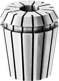
Pinza standard ER20 (DIN 6499)
ER20 collet (DIN 6499)
Realizzato in acciaio per molla.
Rettifica interna ed esterna.
Rugosità inferiore a Rz 2,5.
Capacità ER20: da 1 a 14 mm.
Capacità ER25: da 1 a 16 mm
Campo di serraggio: 1 mm.
Pinza standard ER25 (DIN 6499)
ER25 collet (DIN 6499)
Precisione di runout: 0,015 mm. Manufactured
Articolo
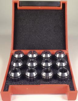
208 Accessori per macchine utensili / Tooling systems Articolo Reference Ø Pinza (mm) Collet Ø (mm) Codice Code PINZA-ER20D5-4-4MP 2-1 69 069 363 PINZA-ER20D6-5-4MP 3-2 69 069 371 PINZA-ER20D7-6-4MP 4-3 69 069 398 PINZA-ER20D8-7-4MP 5-4 69 069 401 PINZA-ER20D9-8-4MP 6-5 69 069 428 PINZA-ER20D10-9-4MP 7-6 69 069 436 PINZA-ER20D11-10-4MP 8-7 69 069 444 PINZA-ER20D12-11-4MP 9-8 69 069 452 PINZA-ER20D13-12-4MP 10-9 69 069 460 PINZA-ER20D14-13-4MP 11-10 69 069 479 PINZA-ER20D12-11-4MP 12-11 69 069 487 PINZA-ER20D13-12-4MP 13-12 69 069 495 PINZA-ER20D14-13-4MP 14-13 69 069 509
in spring steel. Grounded both externally and internally. Grade of roughness lower than Rz 2,5. ER20 Capacity : 1 to 14 mm. ER25 Capacity : 1 to 16 mm Clamping range
1 mm. Concentricity precision : 0,015 mm.
:
Reference Ø Pinza (mm) Collet Ø (mm) Codice Code PINZA-ER25D2-1-4MP 2-1 69 069 517 PINZA-ER25D3-2-4MP 3-2 69 069 525 PINZA-ER25D4-3-4MP 4-3 69 069 533 PINZA-ER25D5-4-4MP 5-4 69 069 541 PINZA-ER25D6-5-4MP 6-5 69 069 568 PINZA-ER25D7-6-4MP 7-6 69 069 576 PINZA-ER25D8-7-4MP 8-7 69 069 584 PINZA-ER25D9-8-4MP 9-8 69 069 592 PINZA-ER25D10-9-4MP 10-9 69 069 606 PINZA-ER25D11-10-4MP 11-10 69 069 614 PINZA-ER25D12-11-4MP 12-11 69 069 622 PINZA-ER25D13-12-4MP 13-12 69 069 630 PINZA-ER25D14-13-4MP 14-13 69 069 649 PINZA-ER25D15-14-4MP 15-14 69 069 657 PINZA-ER25D16-15-4MP 16-15 69 069 665 Articolo Reference Numero di pinze Number of collets Capacità (mm) Capacity (mm) Codice Code PINZA-CEER20COFFRET-4MP 12 2 - 13 69 070 728 Serie di pinze standard ER20 Set of ER20 standard collet Serie di pinze standard ER20 Set of ER25 standard collet (DIN 6499) Su base in legno. (DIN 6499) On wood base. Articolo Reference Numero di pinze Number of collets Capacità (mm) Capacity (mm) Codice Code PINZE-CEER25BOX-4MP 14 3 - 16 69 070 736
Bussole, pinze e accessori Sleeves, collets and accessories 03
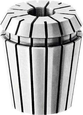
Pinza standard ER32 (DIN 6499)
ER32 collet (DIN 6499)
Realizzato in acciaio per molla.
Rettifica interna ed esterna.
Rugosità inferiore a Rz 2,5.
Capacità ER32: da 2 a 20 mm.
Capacità ER40: da 3 a 26 mm.
Campo di serraggio: 1 mm.
Precisione
0,015 mm.
Pinza standard ER40 (DIN 6499)
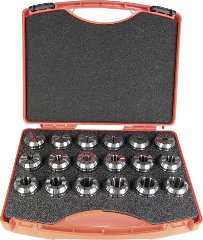
ER40 collet (DIN 6499)
ER32 Capacity : 2 to 20 mm. ER40 Capacity : 3 to 26 mm.
range : 1 mm.
Articolo Reference Ø Pinza (mm) Collet Ø (mm)
209 Accessori per macchine utensili / Tooling systems Articolo Reference Ø Pinza (mm) Collet Ø (mm) Codice Code PINZA-ER32D3-2-4MP 3-2 69 069 673 PINZA-ER32D4-3-4MP 4-3 69 069 681 PINZA-ER32D5-4-4MP 5-4 69 069 703 PINZA-ER32D6-5-4MP 6-5 69 069 711 PINZA-ER32D7-6-4MP 7-6 69 069 738 PINZA-ER32D8-7-4MP 8-7 69 069 746 PINZA-ER32D9-8-4MP 9-8 69 069 754 PINZA-ER32D10-9-4MP 10-9 69 069 762 PINZA-ER32D11-10-4MP 11-10 69 069 770 PINZA-ER32D12-11-4MP 12-11 69 069 789 PINZA-ER32D13-12-4MP 13-12 69 069 797 PINZA-ER32D14-13-4MP 14-13 69 069 800 PINZA-ER32D15-14-4MP 15-14 69 069 819 PINZA-ER32D16-15-4MP 16-15 69 069 827 PINZA-ER32D17-16-4MP 17-16 69 069 835 PINZA-ER32D18-17-4MP 18-17 69 069 843 PINZA-ER32D19-18-4MP 19-18 69 069 851 PINZA-ER32D20-19-4MP 20-19 69 069 878
di runout:
Manufactured in spring steel. Grounded both externally and internally. Grade of roughness lower than Rz 2,5.
Clamping
Concentricity precision : 0,015 mm.
Codice Code PINZA-ER40D4-3-4MP 4-3 69 069 886 PINZA-ER40D5-4-4MP 5-4 69 069 894 PINZA-ER40D6-5-4MP 6-5 69 069 908 PINZA-ER40D7-6-4MP 7-6 69 069 916 PINZA-ER40D8-7-4MP 8-7 69 069 924 PINZA-ER40D9-8-4MP 9-8 69 069 932 PINZA-ER40D10-9-4MP 10-9 69 069 940 PINZA-ER40D11-10-4MP 11-10 69 069 959 PINZA-ER40D13-12-4MP 12-11 69 069 967 PINZA-ER40D14-13-4MP 13-12 69 069 975 PINZA-ER40D15-14-4MP 14-13 69 069 983 PINZA-ER40D16-15-4MP 15-14 69 069 991 PINZA-ER40D17-16-4MP 16-15 69 070 000 PINZA-ER40D18-17-4MP 17-16 69 070 019 PINZA-ER40D19-18-4MP 18-17 69 070 027 PINZA-ER40D20-19-4MP 19-18 69 070 035 PINZA-ER40D21-20-4MP 20-19 69 070 043 PINZA-ER40D22-21-4MP 21-20 69 070 051 PINZA-ER40D23-22-4MP 22-21 69 070 078 PINZA-ER40D24-23-4MP 23-22 69 070 086 PINZA-ER40D25-24-4MP 24-23 69 070 094 PINZA-ER40D26-25-4MP 25-24 69 070 108 PINZA-ER40D26-25-4MP 26-25 69 070 116 Articolo Reference Nombre de pinces Number of collets Capacità (mm) Capacity (mm) Codice Code PINZA-CEER32COFFRET-4MP 18 2 - 20 69 070 744 Set di pinze standard ER32 Set di 18 pinze standard ER32 (DIN 6499) Capacità da 2 a 20 mm. Su base in legno. Set of ER32 standard collets Set of 18 ER32 standard collets (DIN 6499) Capacity 2 to 20 mm. On wood base. Bussole, pinze e accessori Sleeves, collets and accessories 03
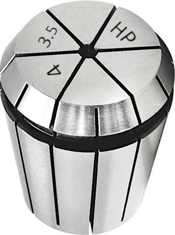
Realizzato in acciaio per molla.
Rettifica interna ed esterna.
Rugosità inferiore a Rz 2,5.
Capacità ER16: da 2 a 10 mm. Capacità ER32: da 3 a 20 mm.
Campo di serraggio: 0,5 mm.
di rotazione: 0,005 garantito
per diametro nominale.
di runout: 0,005 mm.
Bussole, pinze e accessori Sleeves, collets and accessories
210 Accessori per macchine utensili / Tooling systems ØD L2 S Max ØD Min ØD Max Standard Precisione / Precision 1 1,6 6 0,015 0,005 1,6 3 10 0,015 0,005 3 7 16 0,015 0,005 7 10 25 0,015 0,005 10 18 40 0,020 0,005 18 26 50 0,020 0,005 26 40 60 0,020 0,005 0 D L2
CONCENTRICITY PRECISION Articolo Reference Ø Pinza (mm) Collet Ø (mm) Codice Code PINZA-ER16UPD2-4MP 2 69 070 124 PINZA-ER16UPD3-4MP 3 69 070 132 PINZA-ER16UPD4-4MP 4 69 070 140 PINZA-ER16UPD5-4MP 5 69 070 159 PINZA-ER16UPD6-4MP 6 69 070 167 PINZA-ER16UPD8-4MP 8 69 070 175 PINZA-ER16UPD10-4MP 10 69 070 183
(DIN
PRECISIONE DI RUNOUT
Pinza di precisione ER16 (DIN 6499) Precision ER16 Collet (DIN 6499) Pinza di precisione ER32 (DIN 6499) Precision ER32 Collet
6499)
Precisione
Precisione
Grounded
and
Grade of roughness lower than Rz 2,5. ER16 Capacity : 2 to 10 mm. ER32 Capacity : 3 to 20 mm. Clamping range : 0,5 mm. Concentricity precision : 0,005 guarantee only for the nominal diameter. Concentricity precision : 0,005 mm. Articolo Reference Ø Pinza (mm) Collet Ø (mm) Codice Code PINZA-ER32UPD3-4MP 3 69 070 191 PINZA-ER32UPD4-4MP 4 69 070 205 PINZA-ER32UPD5-4MP 5 69 070 213 PINZA-ER32UPD6-4MP 6 69 070 221 PINZA-ER32UPD10-4MP 8 69 070 248 PINZA-ER32UPD12-4MP 10 69 070 256 PINZA-ER32UPD14-4MP 12 69 070 264 PINZA-ER32UPD16-4MP 14 69 070 272 PINZA-ER32UPD18-4MP 16 69 070 280 PINZA-ER32UPD18-4MP 18 69 070 299 PINZA-ER32UPD20-4MP 20 69 070 302
solo
Manufactured in spring steel.
both externally
internally.
03
Pinza a tenuta
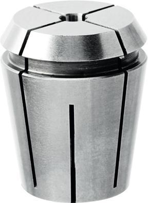
Realizzato in acciaio per molla.
Tenuta meccanica.
Rettifica interna ed esterna.
Rugosità inferiore a Rz 2,5.
Capacità ER16: da 4 a 12 mm.
Capacità ER25: da 4 a 16 mm.
Precisione di runout: 0,008 mm.
Pressione massima: 120 bar.
Pinza
Manufactured in spring steel. Mechanical sealed collet.
Pinza a tenuta stagna ER32 (DIN 6499)
Realizzato in acciaio per molla.
Tenuta meccanica.
Rettifica interna ed esterna.
Rugosità inferiore a Rz 2,5.
Capacità: da 4 a 20 mm.
0,008 mm. Pressione massima: 120 bar.
Sealed Collet ER32 (DIN 6499) Manufactured in spring steel. Mechanical sealed collet. Grounded both externally and internally. Grade of roughness lower than Rz 2,5.
Capacity : 4 to 20 mm. Concentricity precision : 0,008 mm.
Max pressure : 120 bar.

Pinza con foro di lubrificazione ER32 (DIN 6499)
Realizzato in acciaio per molla.
Tenuta meccanica.
Rettifica interna ed esterna.
Rugosità inferiore a Rz 2,5.
Precisione: 0,008 mm.
Pressione massima: 40 bar.
211 Accessori per macchine utensili / Tooling systems
Reference
(mm) Collet Ø (mm) Codice Code PINCE-ER16D3-ET-4MP 3 69 070 310 PINCE-ER16D4-ET-4MP 4 69 070 329 PINCE-ER16D6-ET-4MP 6 69 070 337 PINCE-ER16D8-ET-4MP 8 69 070 345 PINCE-ER16D10-ET-4MP 10 69 070 353 PINCE-ER16D12-ET-4MP 12 69 070 361
Articolo
Ø Pinza
stagna ER16 (DIN 6499) Sealed Collet ER16 (DIN 6499)
a tenuta stagna ER25 (DIN 6499) Sealed Collet ER25
ER16 Capacity
ER25 Capacity
Concentricity precision
mm. Max pressure
Reference Ø Pinza (mm) Collet Ø (mm) Codice Code PINCE-ER25D4-ET-4MP 4 69 070 388 PINCE-ER25D6-ET-4MP 6 69 070 396 PINCE-ER25D8-ET-4MP 8 69 070 418 PINCE-ER25D10-ET-4MP 10 69 070 426 PINCE-ER25D12-ET-4MP 12 69 070 434 PINCE-ER25D14-ET-4MP 14 69 070 442 PINCE-ER25D16-ET-4MP 16 69 070 450 Articolo Reference Ø Pinza (mm) Collet Ø (mm) Codice Code PINCE-ER32D4-ET-4MP 4 69 070 469 PINCE-ER32D6-ET-4MP 6 69 070 477 PINCE-ER32D8-ET-4MP 8 69 070 485 PINCE-ER32D10-ET-4MP 10 69 070 493 PINCE-ER32D12-ET-4MP 12 69 070 507 PINCE-ER32D14-ET-4MP 14 69 070 515 PINCE-ER32D16-ET-4MP 16 69 070 523 PINCE-ER32D18-ET-4MP 18 69 070 531 PINCE-ER32D20-ET-4MP 20 69 070 558
Grounded both externally and internally. Grade of roughness lower than Rz 2,5.
: 4 to 12 mm.
: 4 to 16 mm.
: 0,008
: 120 bar. Articolo
Precisione:
Articolo Reference Ø Pinza (mm) Collet Ø (mm) Codice Code PINCE-ER32D3-ARROS-4MP 3 69 071 473 PINCE-ER32D4-ARROS-4MP 4 69 071 481 PINCE-ER32D5-ARROS-4MP 5 69 071 503 PINCE-ER32D6-ARROS-4MP 6 69 071 511 PINCE-ER32D8-ARROS-4MP 8 69 071 538 PINCE-ER32D10-ARROS-4MP 10 69 071 546 PINCE-ER32D12-ARROS-4MP 12 69 071 554 PINCE-ER32D16-ARROS-4MP 16 69 071 562 PINCE-ER32D20-ARROS-4MP 20 69 071 570
Concentricity
Max pressure
Externally cooled collet (DIN 6499) Manufactured in spring steel. Collet with coolant hole. Grounded both externally and internally. Grade of roughness lower than Rz 2,5.
precision : 0,008 mm.
: 40 bar.
03
Bussole, pinze e accessori Sleeves, collets and accessories
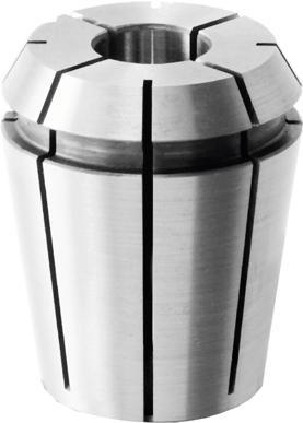
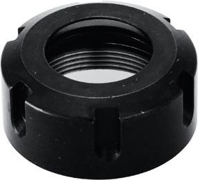
Pinza di maschiatura ER16 (DIN 6499)
Realizzato in acciaio per molla.
Pinza di maschiatura con quadro interno.
Rettifica interna ed esterna.
Rugosità inferiore a Rz 2,5.
Precisione: 0,015 mm.
Norma standard DIN 371-376.
Pinza di maschiatura ER32 (DIN 6499)
Realizzato in acciaio per molla. Pinza di maschiatura con quadro interno. Rettifica interna ed esterna. Rugosità inferiore a Rz 2,5. Precisione: 0,015 mm. Norma standard DIN 371-376.
Tap Collet ER16 (DIN 6499)
Manufactured in spring steel. Tapping collets with internal square.
Grounded both externally and internally.
Grade of roughness lower than Rz 2,5.
Concentricity precision : 0,015 mm.
Standard norm DIN 371-376.
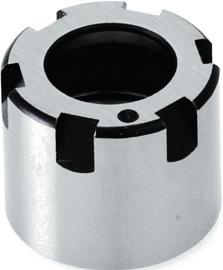
Tap Collet ER32 (DIN 6499)
Manufactured in spring steel. Tapping collets with internal square. Grounded both externally and internally. Grade of roughness lower than Rz 2,5. Concentricity precision : 0,015 mm. Standard norm DIN 371-376.
212 Accessori per macchine utensili / Tooling systems Articolo Reference Ø Pinza D (mm) Collet Ø D (mm) Quadro SQ Shank square SQ Per maschio For tap Norma Norm Codice Code PINZA-ER16D3.5-TAR-4MP 3,5 2,7 M3 DIN 371 69 070 566 PINZA-ER16D4.5-TAR-4MP 4,5 3,4 M4 DIN 371 69 070 574 PINZA-ER16D6-TAR-4MP 6 4,9 M5 / M6 DIN 371 69 070 582 PINZA-ER16D7-TAR-4MP 7 5,5 M10 DIN 376 69 070 590 PINZA-ER16D8-TAR-4MP 8 6,2 M8 DIN 371 69 070 604
ØD SQ
Articolo Reference Ø Pinza D (mm) Collet Ø D (mm) Quadro SQ Shank square SQ Per maschio For tap Norma Norm Codice Code PINZA-ER32D3.5-TAR-4MP 3,5 2,7 M3 DIN 371 69 140 394 PINZA-ER32D4.5-TAR-4MP 4,5 3,4 M4 DIN 371 69 140 408 PINZA-ER32D6-TAR-4MP 6 4,9 M5 / M6 DIN 371 69 140 416 PINZA-ER32D7-TAR-4MP 7 5,5 M10 DIN 376 69 140 424 PINZA-ER32D8-TAR-4MP 8 6,2 M8 DIN 371 69 140 432 PINZA-ER32D9-TAR-4MP 9 7 M12 DIN 376 69 140 440 PINZA-ER32D10-TAR-4MP 10 8 M10 DIN 371 69 140 459 PINZA-ER32D11-TAR-4MP 11 9 M14 DIN 376 69 140 467 PINZA-ER32D11-TAR-4MP 12 9 M16 DIN 376 69 140 475 PINZA-ER32D16-TAR-4MP 16 12 M20 DIN 376 69 140 483 ØD SQ
Articolo Reference Per pinze For collet Ø Esterno (mm) External Ø (mm) Codice Code GHIERA-STD-ER16-4MP ER16 32 69 071 155 GHIERA-STD-ER25-4MP ER25 42 69 071 163 GHIERA-STD-ER32-4MP ER32 50 69 071 171 GHIERA-STD-ER40-4MP ER40 63 69 071 198
ER DIN
Standard clamping nut for ER collet chuck ER DIN 6499 Articolo Reference Per pinze For collet Ø Esterno (mm) External Ø (mm) Codice Code GHIERA-ER11MINI-4MP ER11 16 69 071 112 GHIERA-ER16MINI-4MP ER16 22 69 071 120 GHIERA-ER20MINI-4MP ER20 28 69 071 139 GHIERA-ER25MINI-4MP ER25 35 69 071 147
Ghiera standard per portapinza
ER
6499
ER ER DIN
clamping nut for ER collet chuck ER DIN 6499
pinze e accessori Sleeves, collets and accessories 03
Mini ghiera per portapinza
6499 Mini
Bussole,
Bussole, pinze e accessori
Sleeves, collets and accessories
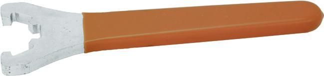
Chiave di serraggio a 4 denti per ghiera standard ER ER
Wrench for ER standard clamping nut
Chiave di serraggio per ghiera mini ER
Wrench for ER mini clamping nut
power milling chuck
Smontaconi
Consente l'orientamento dei portautensili sugli assi verticale e orizzontale.
Robusto corpo in acciaio.
Consente l'adattamento di attacchi
standard ISO (DIN 69871), BT, DIN 2080 e HSK-A. Dotato di viti di fermo e viti di sicurezza, oltre a 4 fori per il fissaggio al tavolo.
Indexable assembly universal support
Head fixture can be set in two position, vertical and horizontal, for easy access to the cutting tool.
Robust steel body.
Suitable for Norm SK (DIN 69871), BT, DIN 2080 and HSK-A.
Can be mounted on work table with four screws
Supplied with a positionning screw and a security screw.
213 Accessori per macchine utensili / Tooling systems
Reference Codice Code CHIAVE-ER16-ERGOT-4MP 69 071 074 CHIAVE-ER25-ERGOT-4MP 69 071 163 CHIAVE-ER32-ERGOT-4MP 69 071 171 CHIAVE-ER40-ERG0T-4MP 69 071 198
Articolo
DIN
6499
ER DIN
6499
DIN
ER
6499
ER DIN
Articolo Reference Codice Code CHIAVE-ER11-MINI-4MP 69 071 023 CHIAVE-ER16-MINI-4MP 69 071 031 CHIAVE-ER20-MINI-4MP 69 071 058 CHIAVE-ER25-MINI-4MP 69 071 066 Articolo Reference Codice Code CHIAVE MANDRINO HP-D20-4MP 69 138 608 CHIAVE MANDRINO HP-D32-4MP 69 138 616
for
Articolo Reference Per mandrino Ø For toolholder Ø Codice Code CHIAVE PF-D16-4MP 16 69 138 624 CHIAVE PF-D22-4MP 22 69 138 632 CHIAVE PF-D27-4MP 27 69 138 640 CHIAVE PF-D32-4MP 32 69 138 659 CHIAVE PF-D40-4MP 40 69 138 667 Chiave di serraggio mandrino porta-fresa a foro liscio Per viti a croce
for shell end mill holder For cross screw Articolo Reference Ø (mm) Codice Code CENTRATORE-D10X10-4MP 10X10 69 138 691 CENTRATORE-D10X4-4MP 10X4 69 071 236 Centratore Floating precision centering device Articolo Reference Ø D (mm) H (mm) Base (mm) Per attacco For shank Codice Code SUPPORTO-CONO40-HSK63-C6-4MP 63 160 150 ISO40 (DIN 69871), SA40 (DIN2080), BT40, HSK63A69 071 201 SUPPORTO-CONO50-HSK100-C10-4MP 100 210 200 ISO50 (DIN 69871), SA50(DIN2080), BT50, HSK100A69 071 228
6499
Chiave per mandrino a forte serraggio Wrench
Wrench
03
Bussola di riduzione
cilindrica per tornio
Bussola di riduzione per tornio con collare.
Per il montaggio di barre di alesatura o utensili piatti.
Con serraggio a vite o luce.
Cylindrical reduction sleeve for lathe Headed reduction sleeve For boring bar or tool with flat shank With screw or slot.
214 Accessori per macchine utensili / Tooling systems Articolo Reference Ø Esterno D (mm) External Ø D (mm) Ø Interno D1 (mm) Internal Ø D1 (mm) Lunghezza L (mm) Length L (mm) Serraggio Clamping Codice Code REDUC-D20X6X55VIS-4MP 20 6 55 Vite / Screw 69 070 752 REDUC-D20X8X55VIS-4MP 20 8 55 Vite / Screw 69 070 760 REDUC-D20X10X55VIS-4MP 20 10 55 Vite / Screw 69 070 779 REDUC-D20X12X55VIS-4MP 20 12 55 Vite / Screw 69 070 787 REDUC-D25X6X65VIS-4MP 25 6 65 Vite / Screw 69 070 795 REDUC-D25X8X65VIS-4MP 25 8 65 Vite / Screw 69 070 809 REDUC-D25X10X65VIS-4MP 25 10 65 Vite / Screw 69 070 817 REDUC-D25X12X65VIS-4MP 25 12 65 Vite / Screw 69 070 825 REDUC-D25X16X65LUM-4MP 25 16 65 Luce / Slot 69 070 833 REDUC-D25X20X65LUM-4MP 25 20 65 Luce / Slot 69 070 841 REDUC-D32X6X70VIS-4MP 32 6 70 Vite / Screw 69 070 868 REDUC-D32X8X70VIS-4MP 32 8 70 Vite / Screw 69 070 876 REDUC-D32X10X70VIS-4MP 32 10 70 Vite / Screw 69 070 884 REDUC-D32X12X70VIS-4MP 32 12 70 Vite / Screw 69 070 892 REDUC-D32X16X70VIS-4MP 32 16 70 Vite / Screw 69 070 906 REDUC-D32X20X70VLUM-4MP 32 20 70 Luce / Slot 69 070 914 REDUC-D32X25X70LUM-4MP 32 25 70 Luce / Slot 69 070 922 REDUC-D40X6X80VIS-4MP 40 6 80 Vite / Screw 69 070 930 REDUC-D40X8X80VIS-4MP 40 8 80 Vite / Screw 69 070 949 REDUC-D40X10X80VIS-4MP 40 10 80 Vite / Screw 69 070 957 REDUC-D40X12X80VIS-4MP 40 12 80 Vite / Screw 69 070 965 REDUC-D40X16X80VIS-4MP 40 16 80 Vite / Screw 69 070 973 REDUC-D40X20X80VIS-4MP 40 20 80 Vite / Screw 69 070 981 REDUC-D40X25X80VIS-4MP 40 25 80 Vite / Screw 69 071 007 REDUC-D40X32X80LUM-4MP 40 32 80 Luce / Slot 69 071 015
L 0 D1 0 D
pinze
Sleeves, collets and accessories 03
Bussole,
e accessori
NOTE NOTES
215
NOTE NOTES
216
NOTE NOTES
217
NOTE NOTES
218
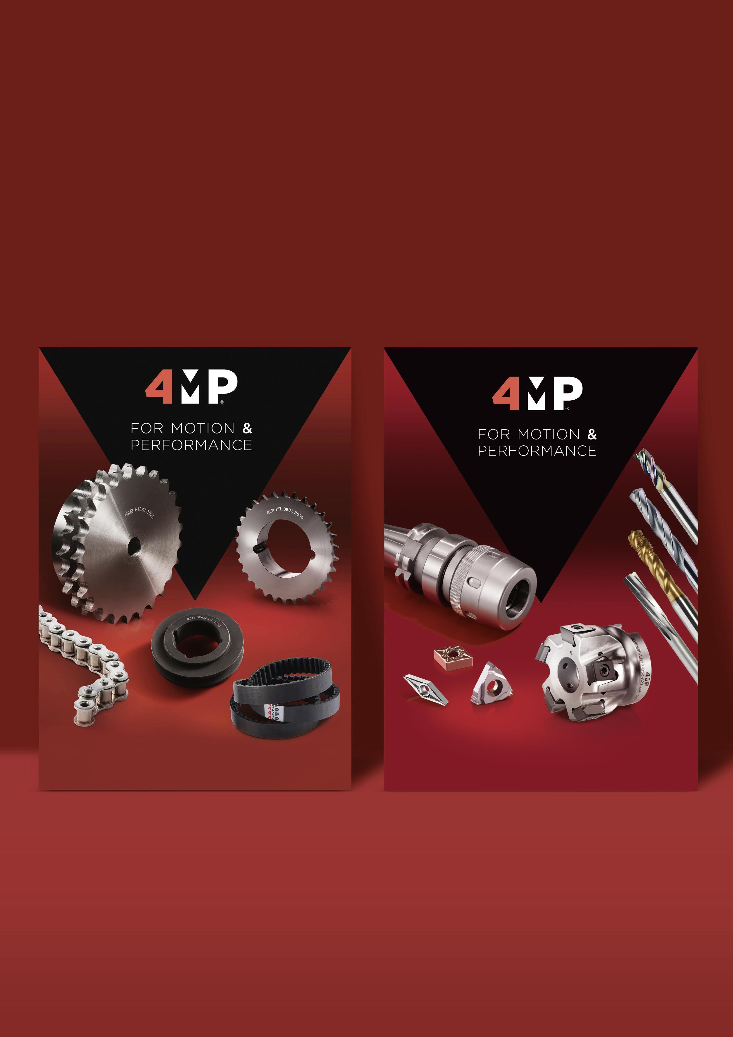
SCOPRI TUTTI I NOSTRI PRODOTTI NEI NOSTRI CATALOGHI DISCOVER ALL OUR PRODUCTS IN OUR CATALOGUES TRASMISSIONE DI POTENZA - POWER TRANSMISSION Componenti meccanici, cinghie e catene Irons, belts & chains LAVORAZIONE - MACHINING Utensili integrali, inserti, porta-inserti eaccessori per macchine utensili Solidroundtools,inserts,toolholders&accessories

For Motion & Performance Movimento e Prestazioni.Creazione/Realizzazione: Edizione maggio 2023 Edition May 2023
