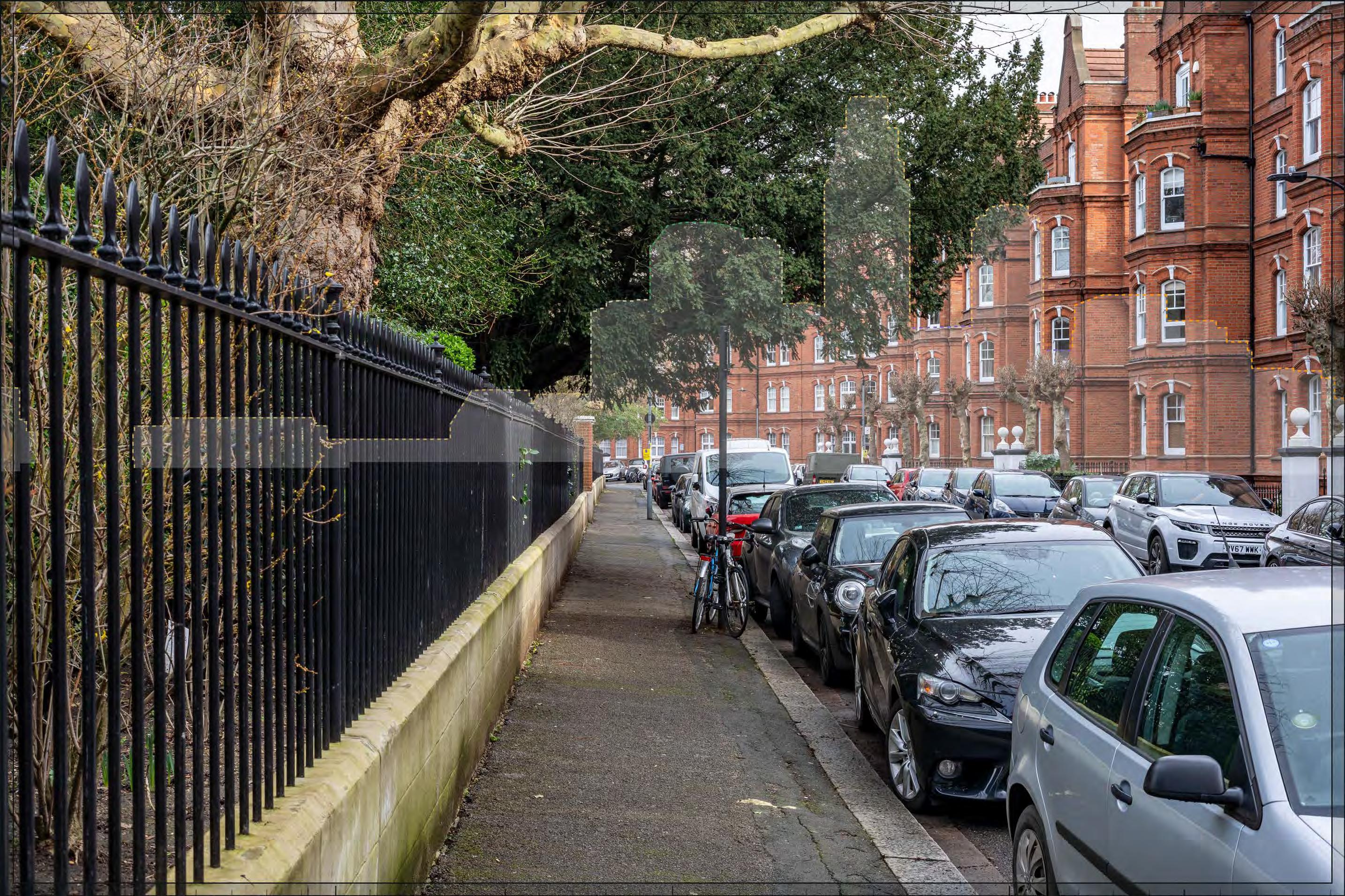
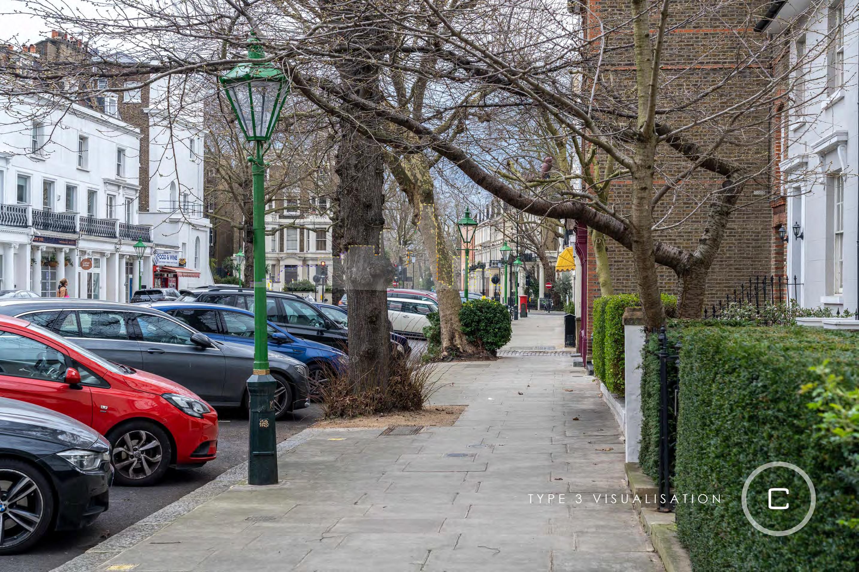
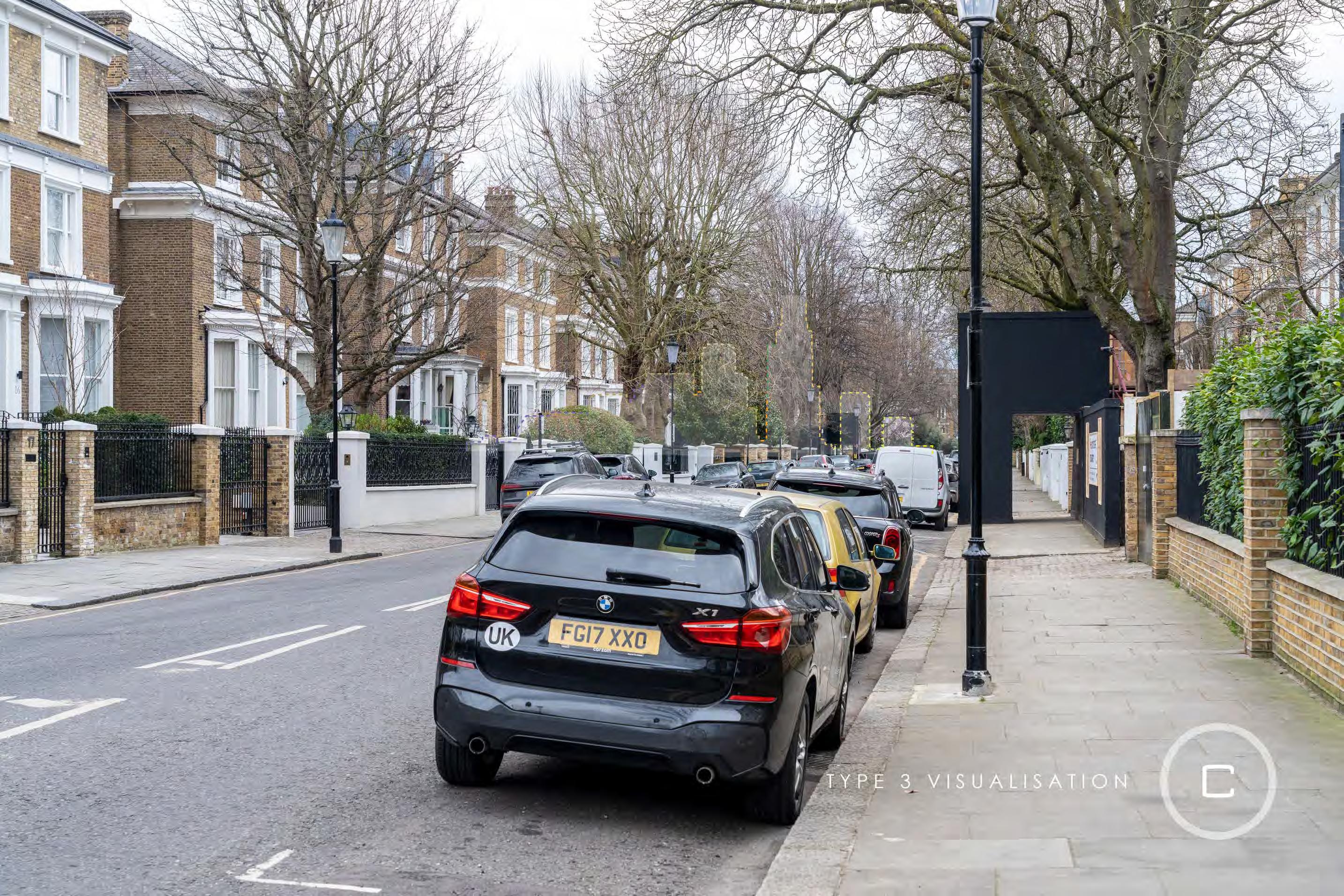
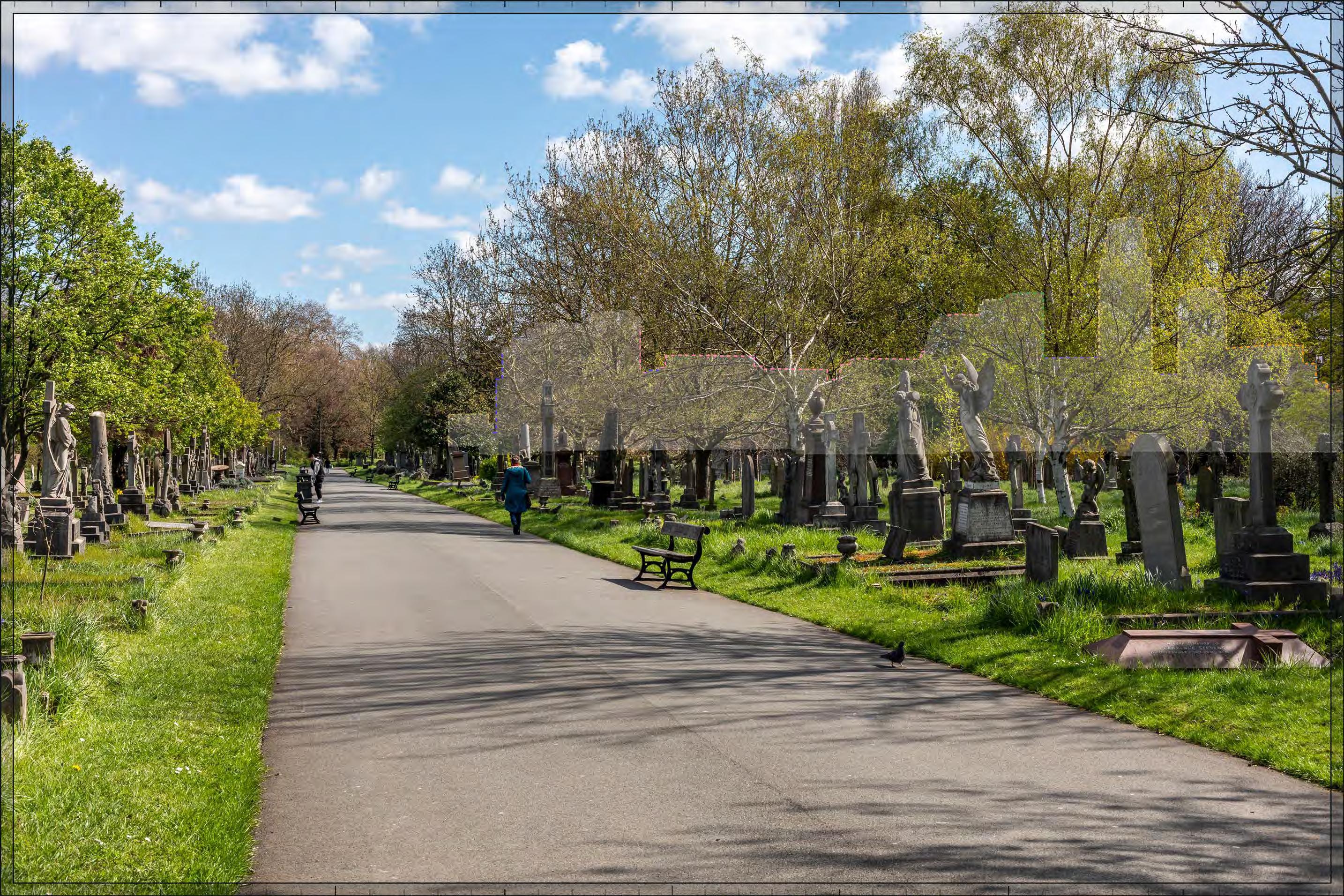
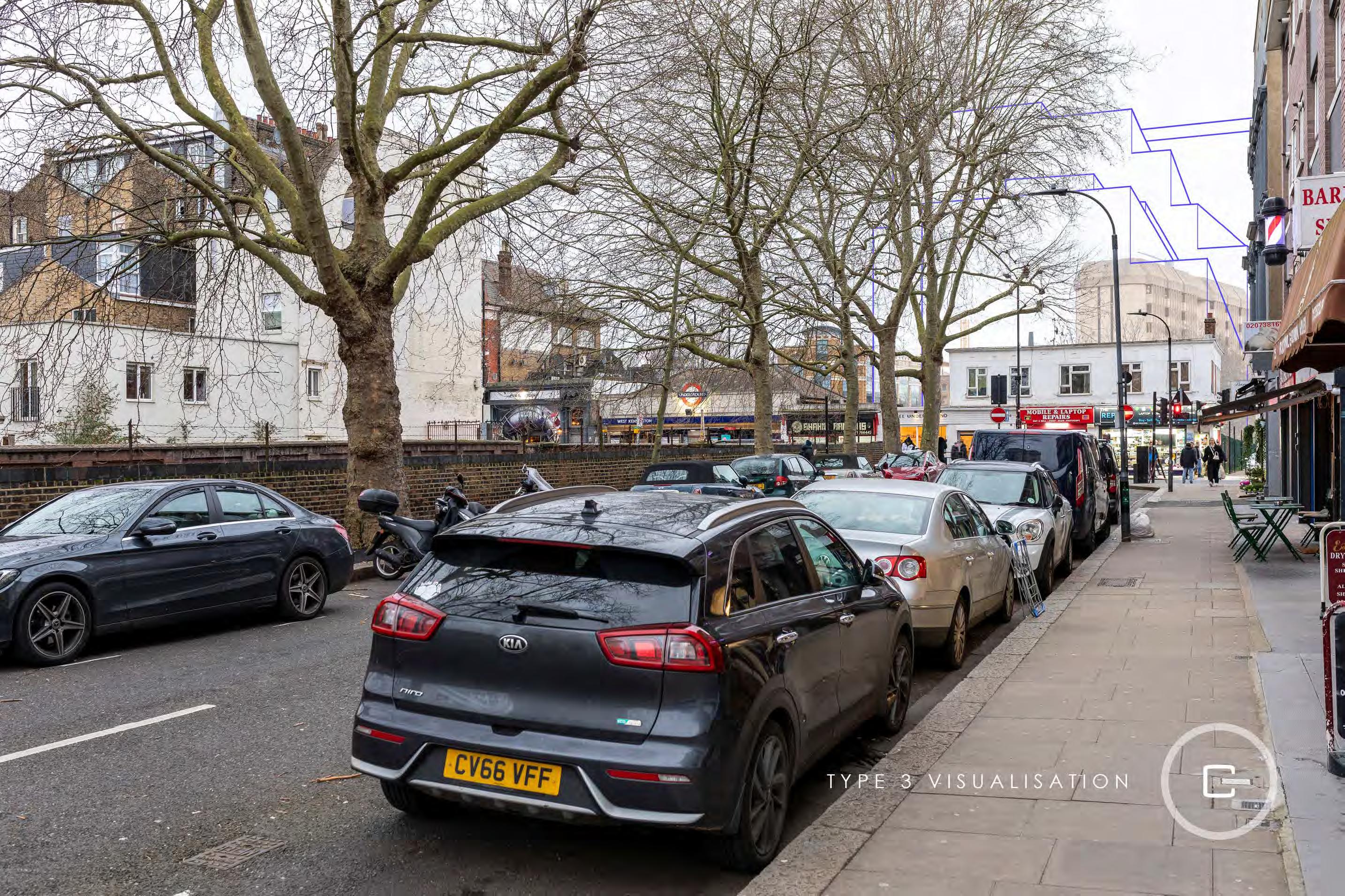
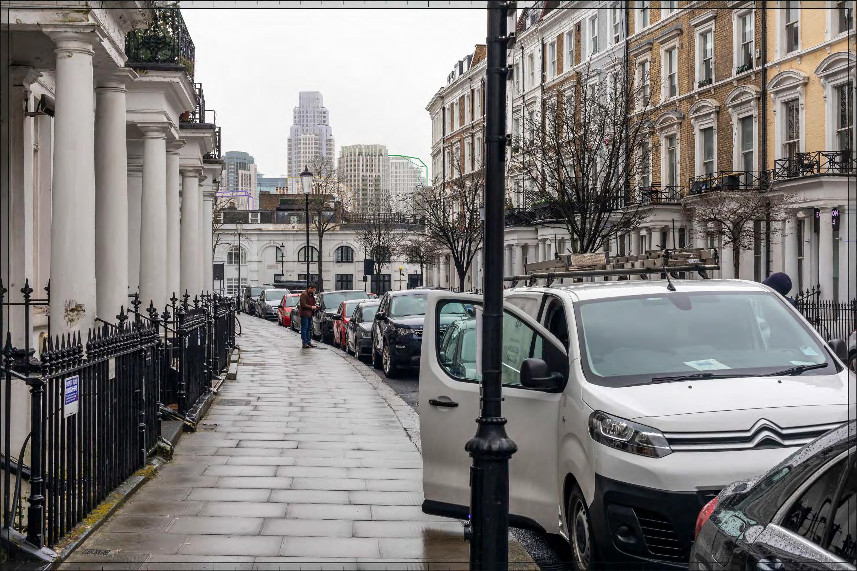
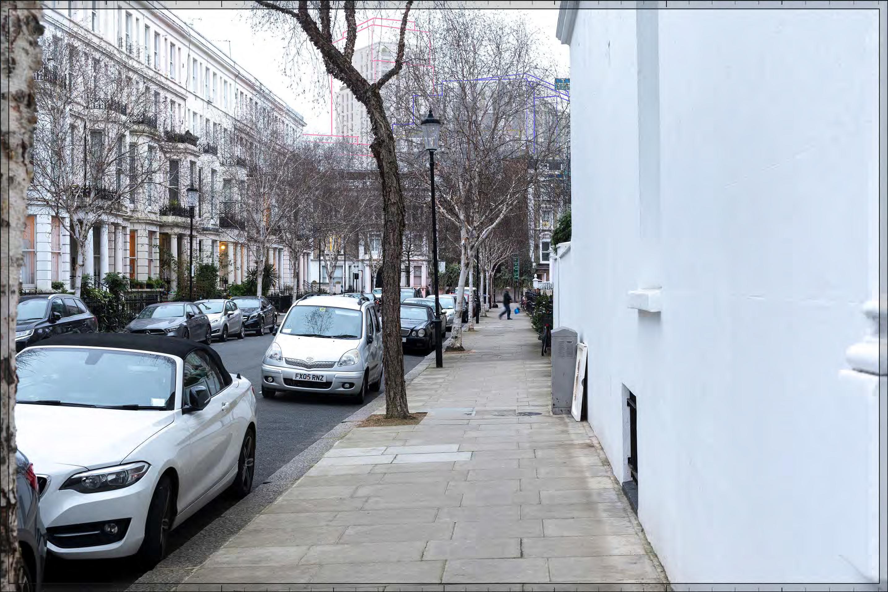
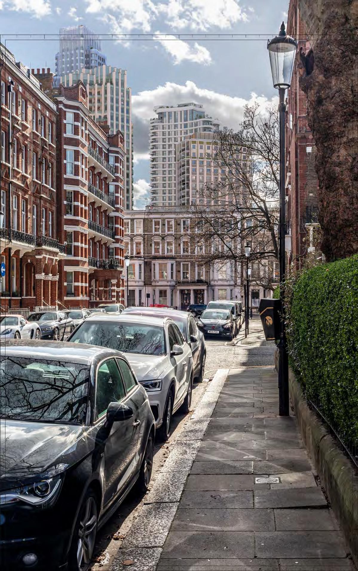
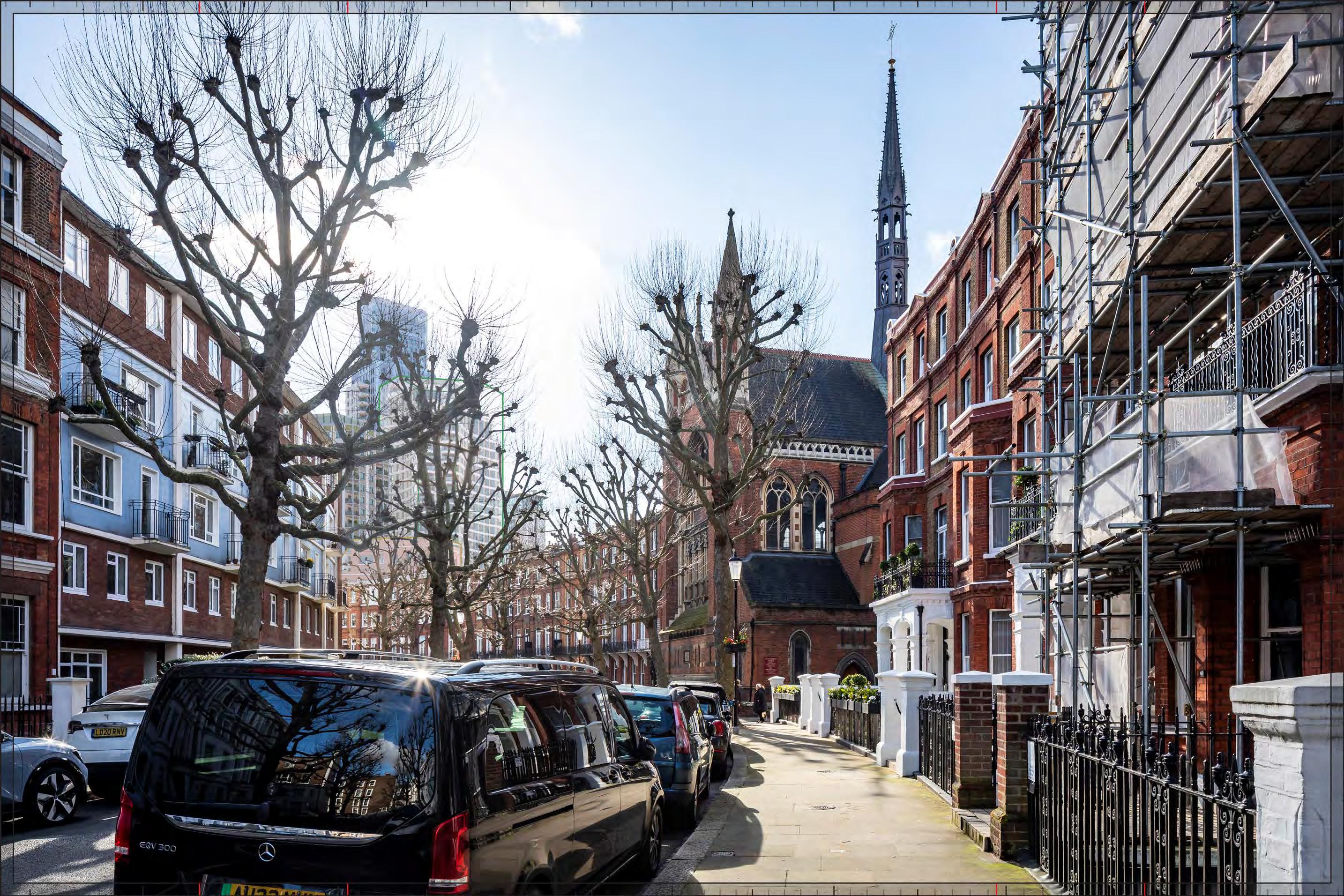
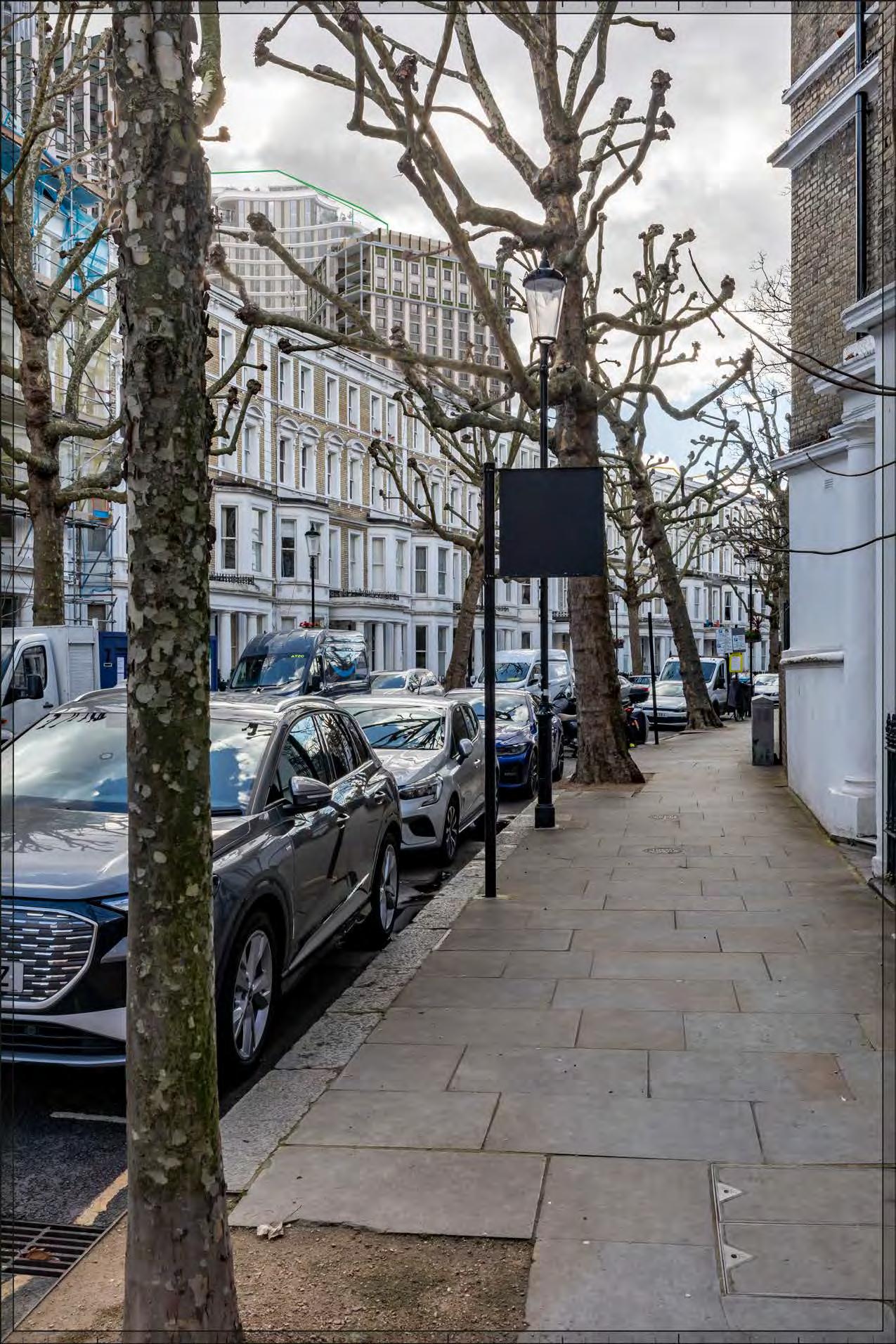
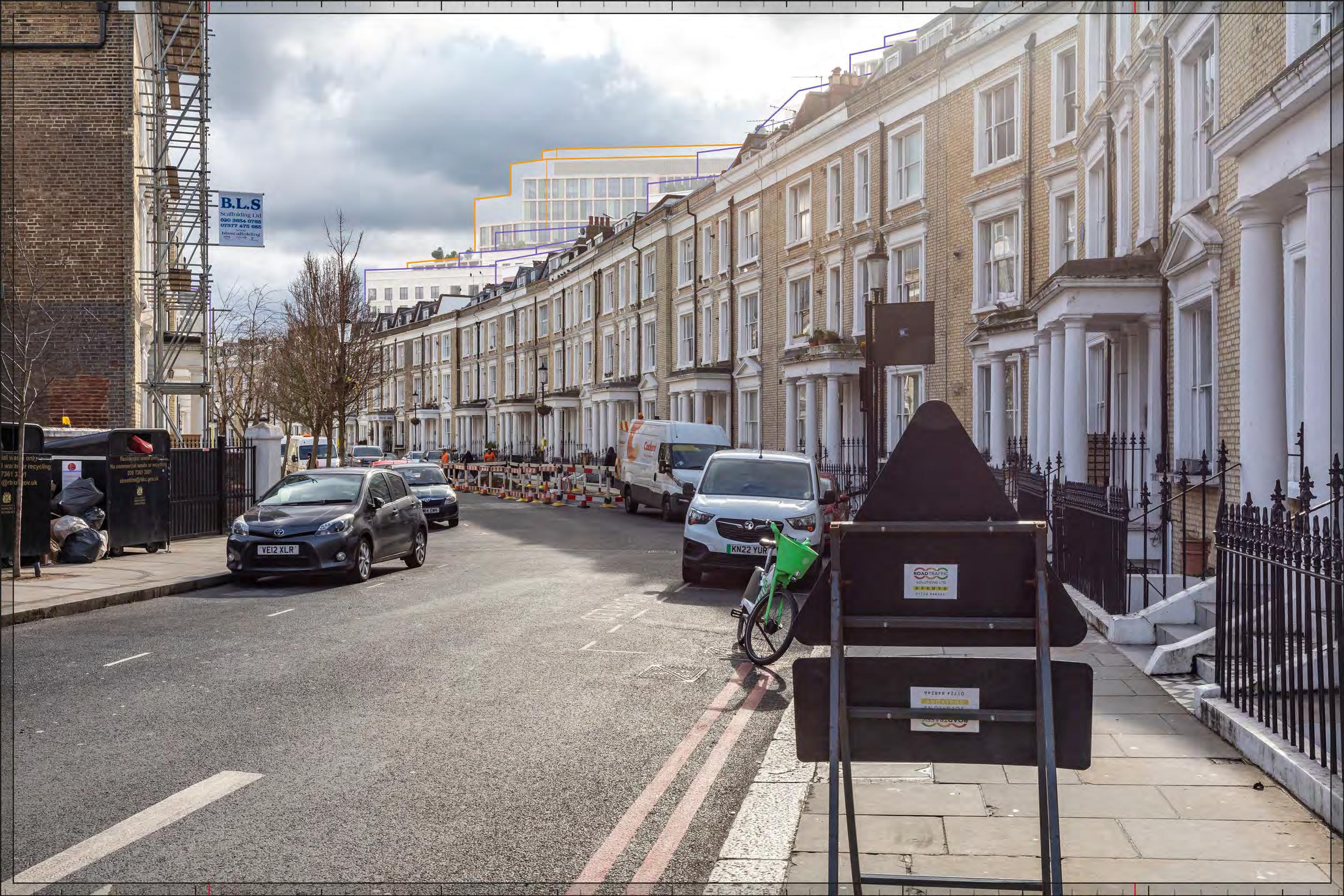
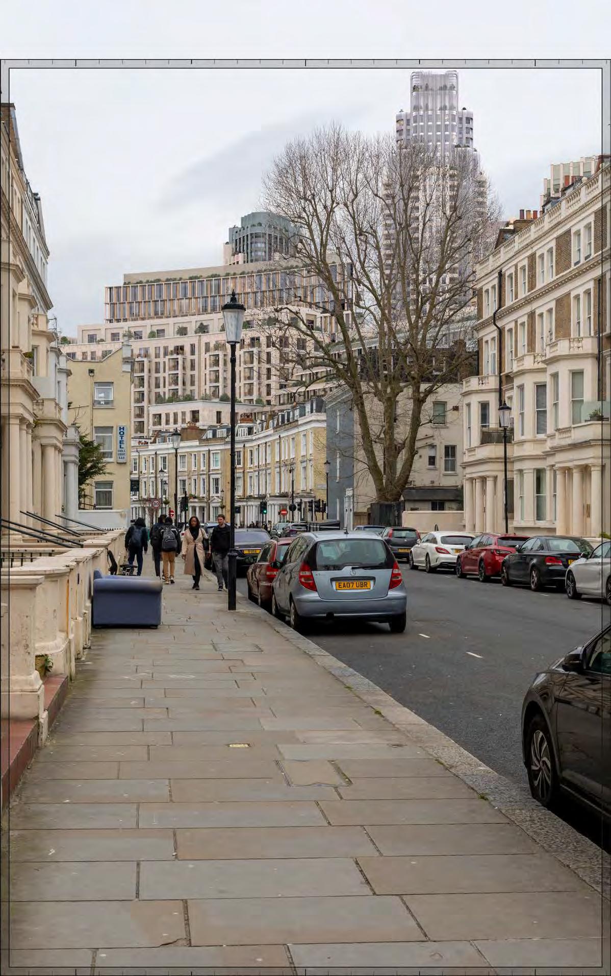
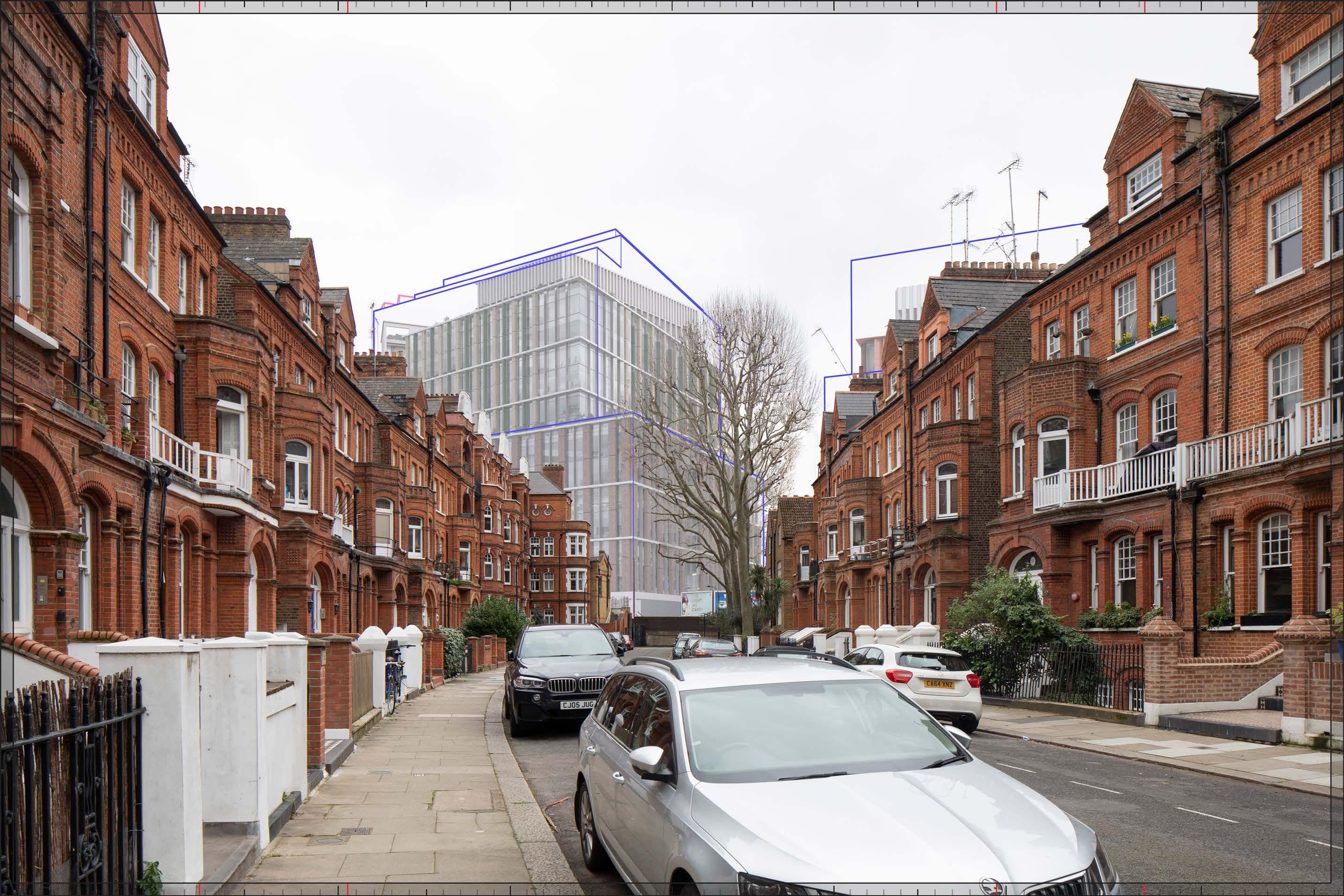
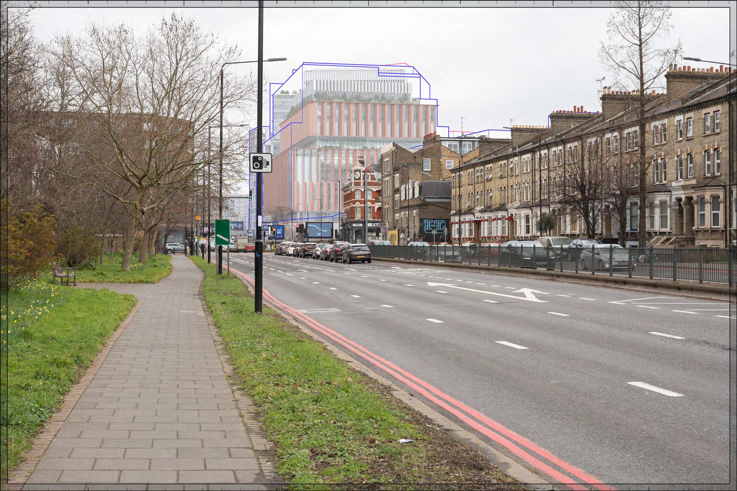
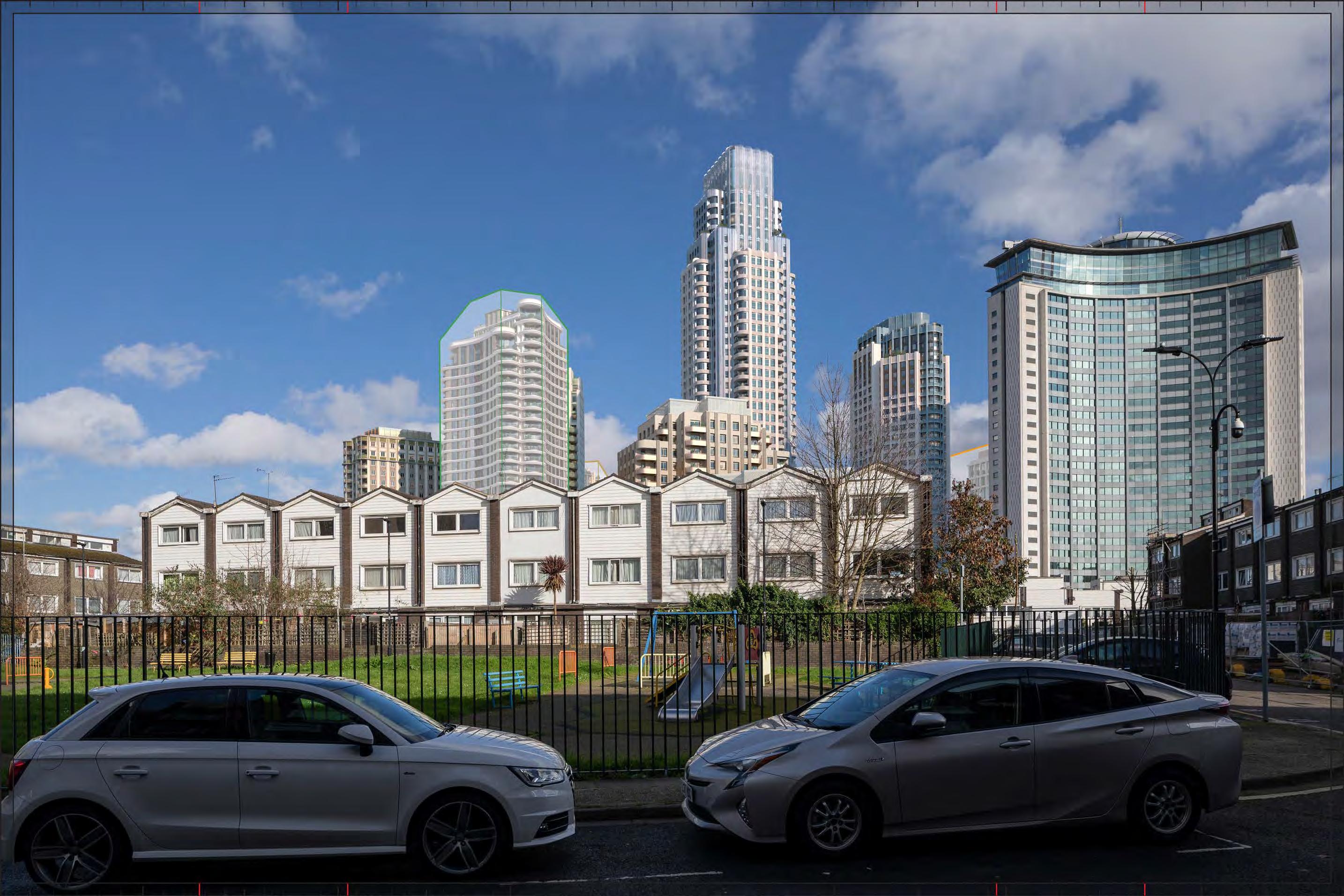
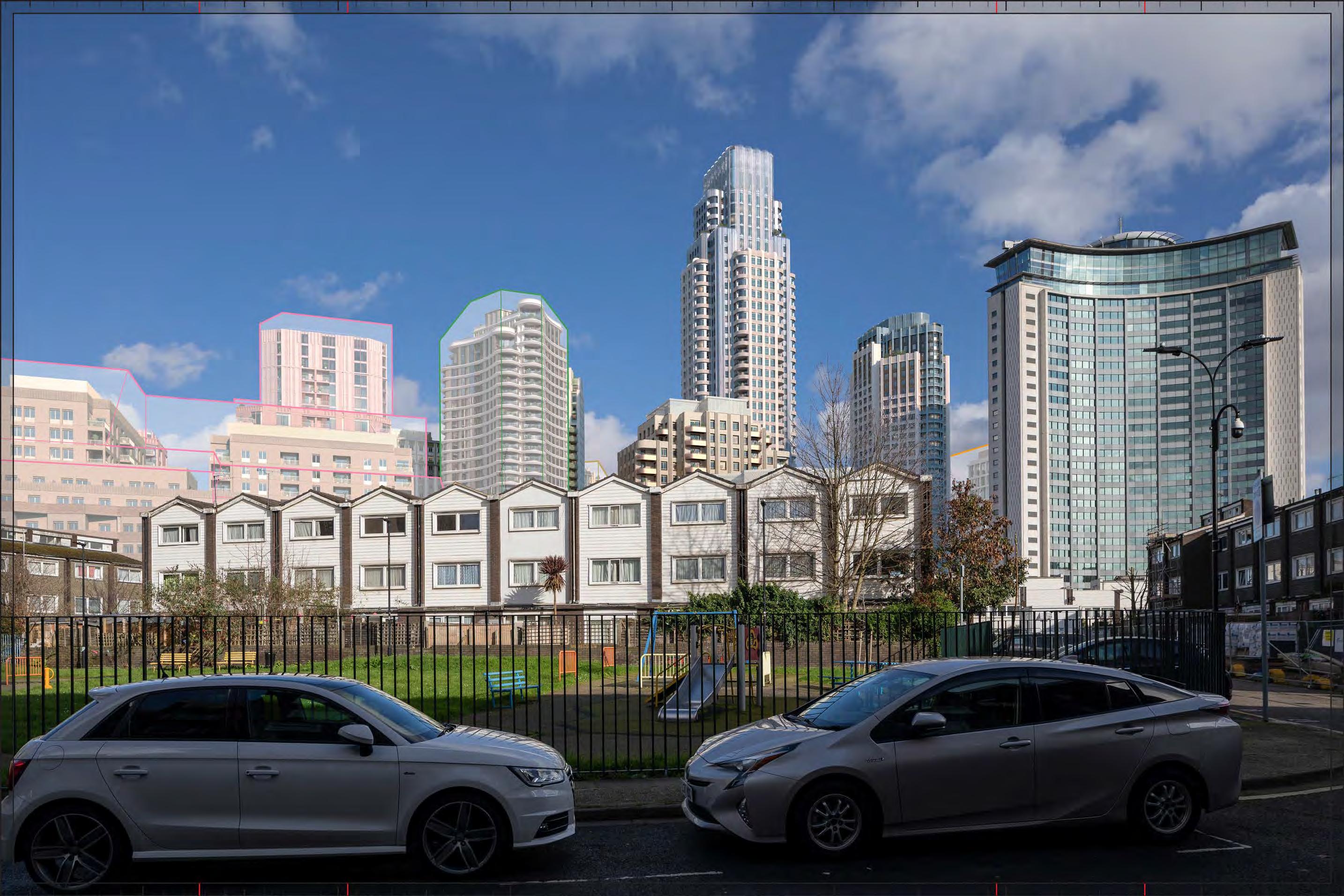
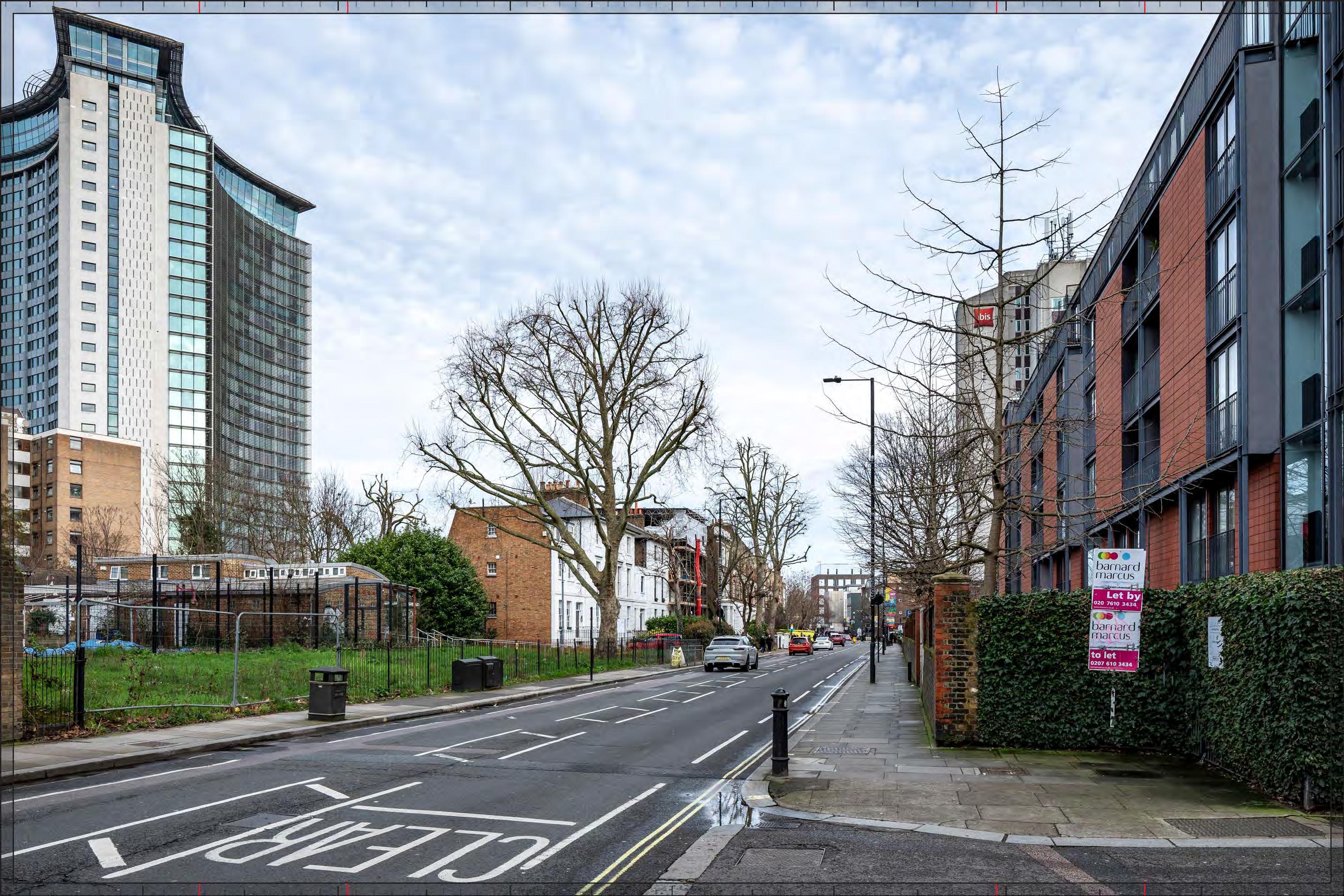
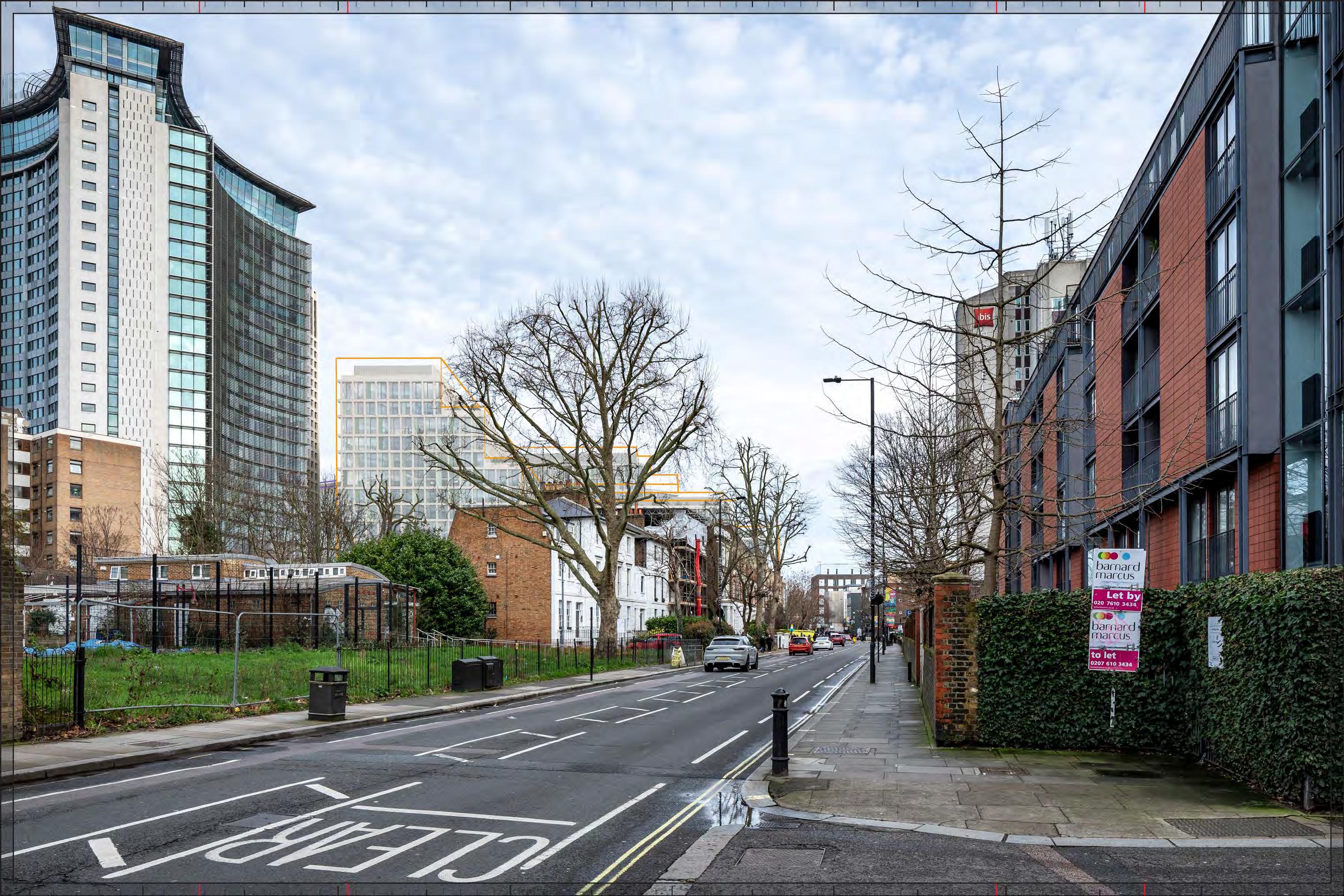
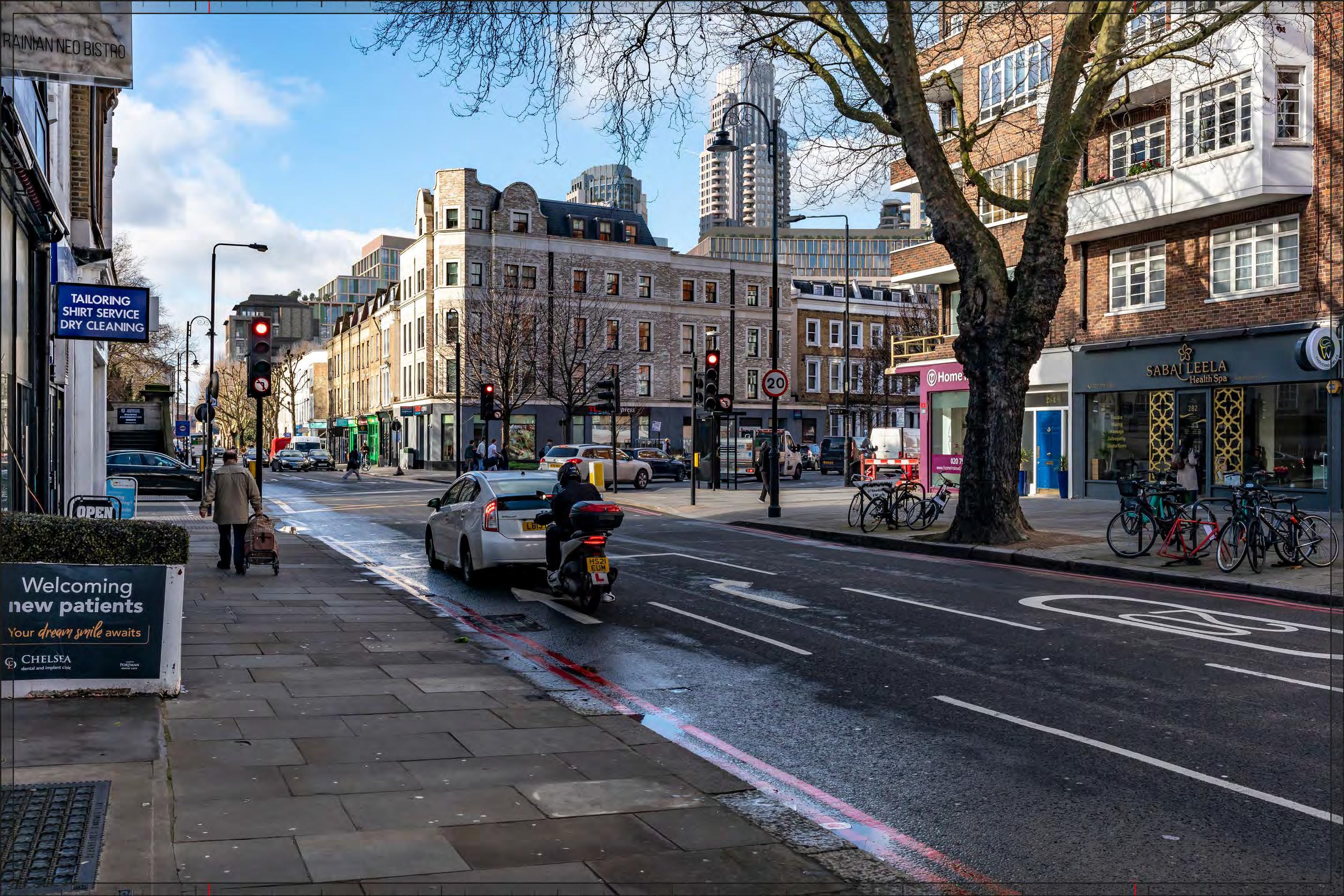
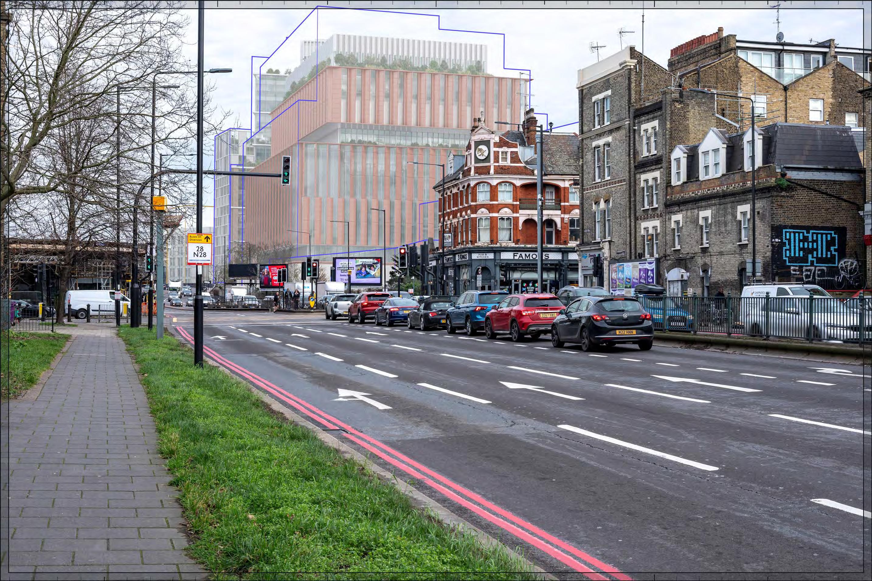
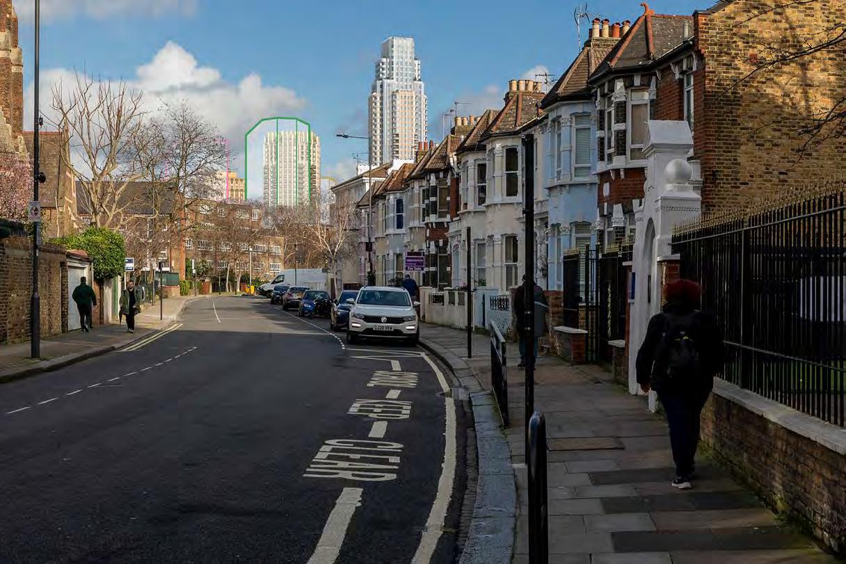
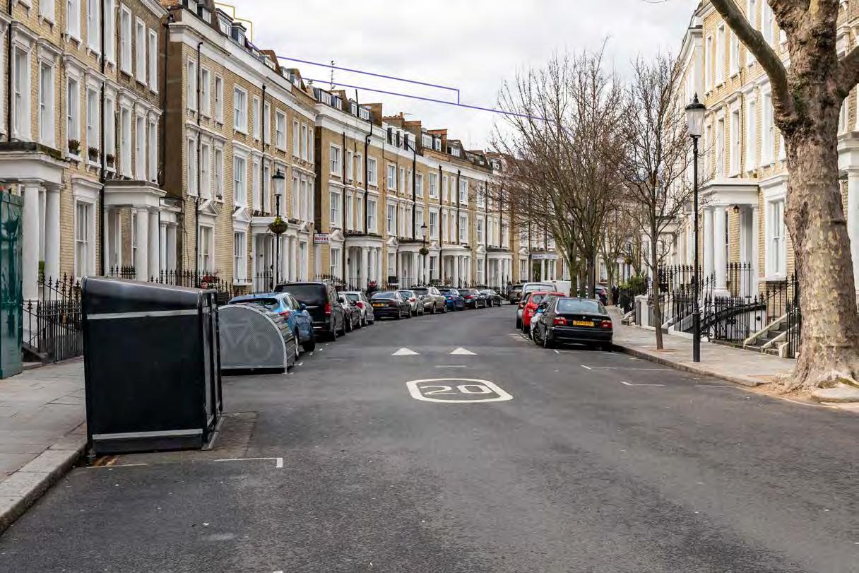
Proposed illustrative render of Outline Component within maximum parameter, Early Phases
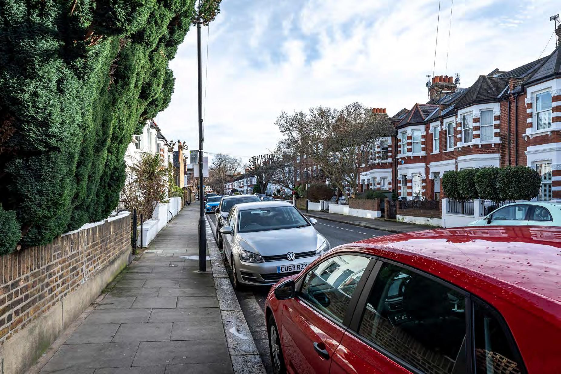
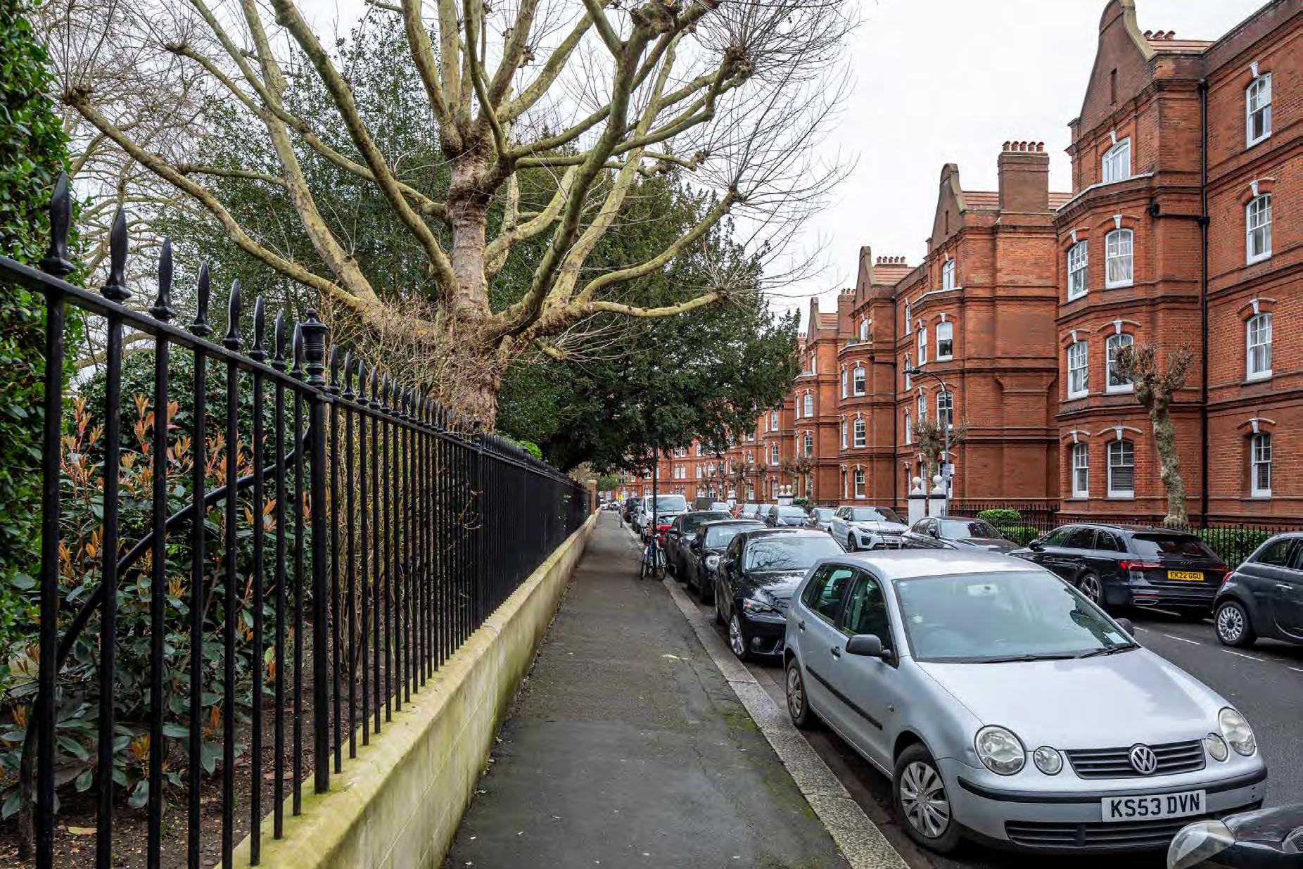
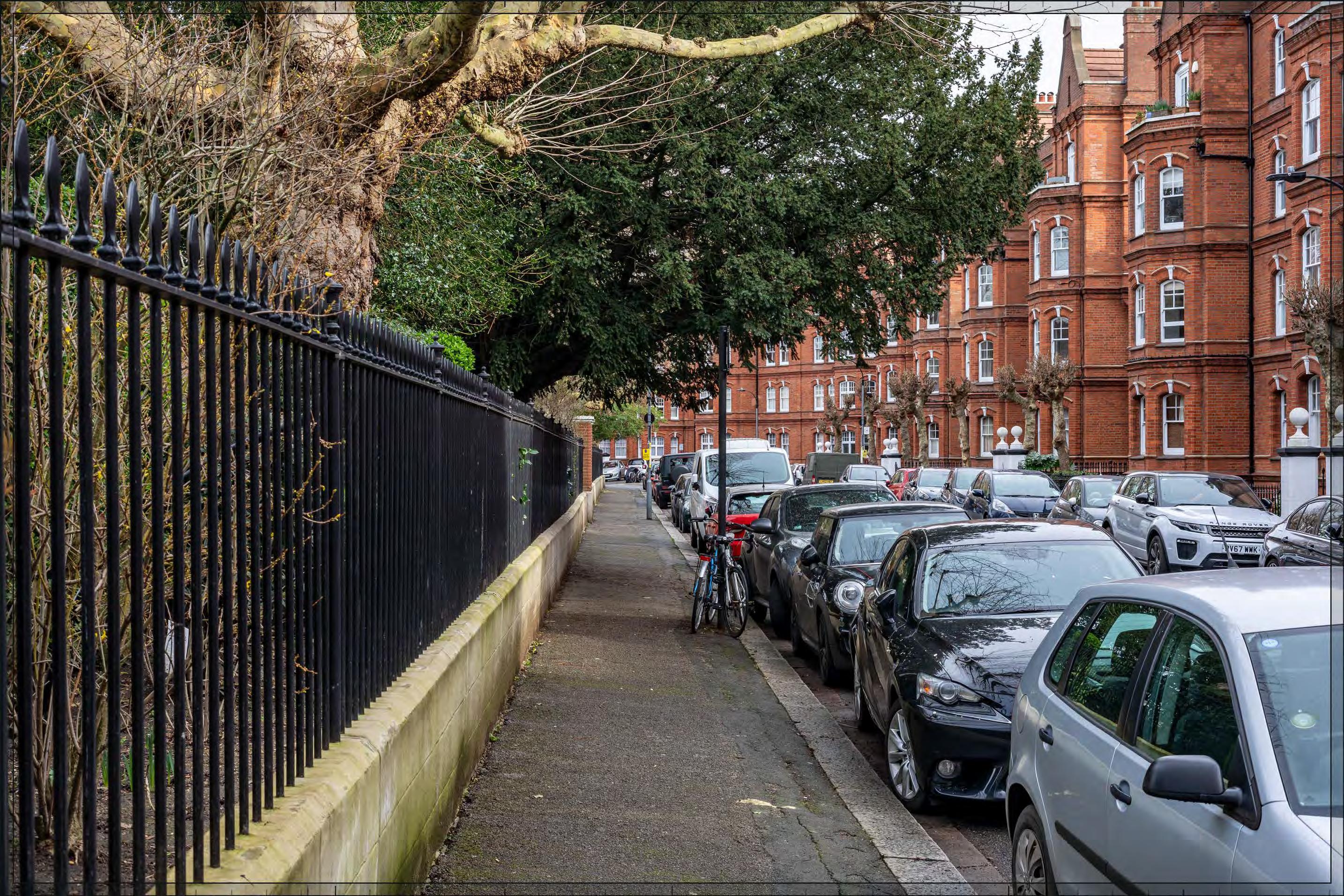
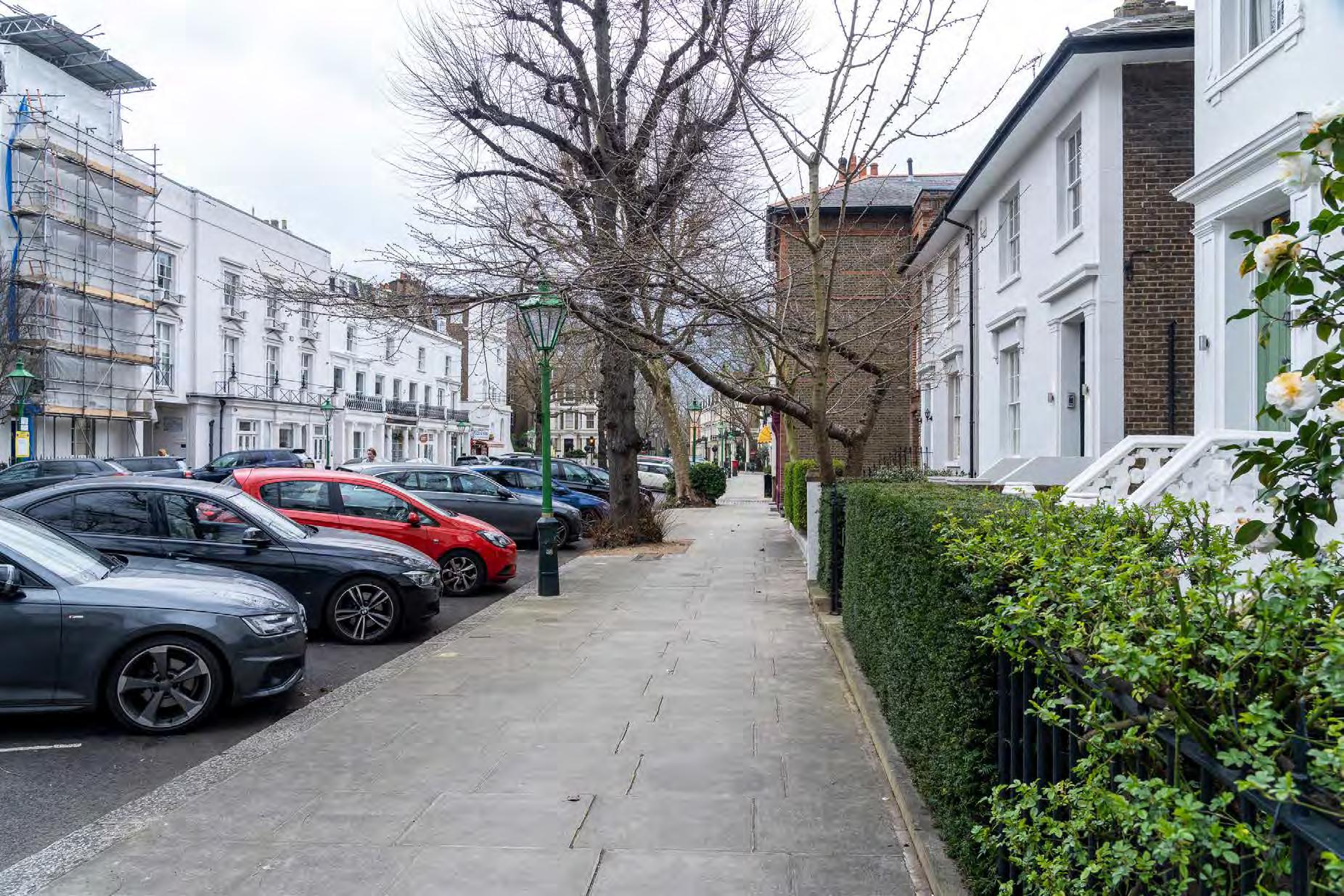
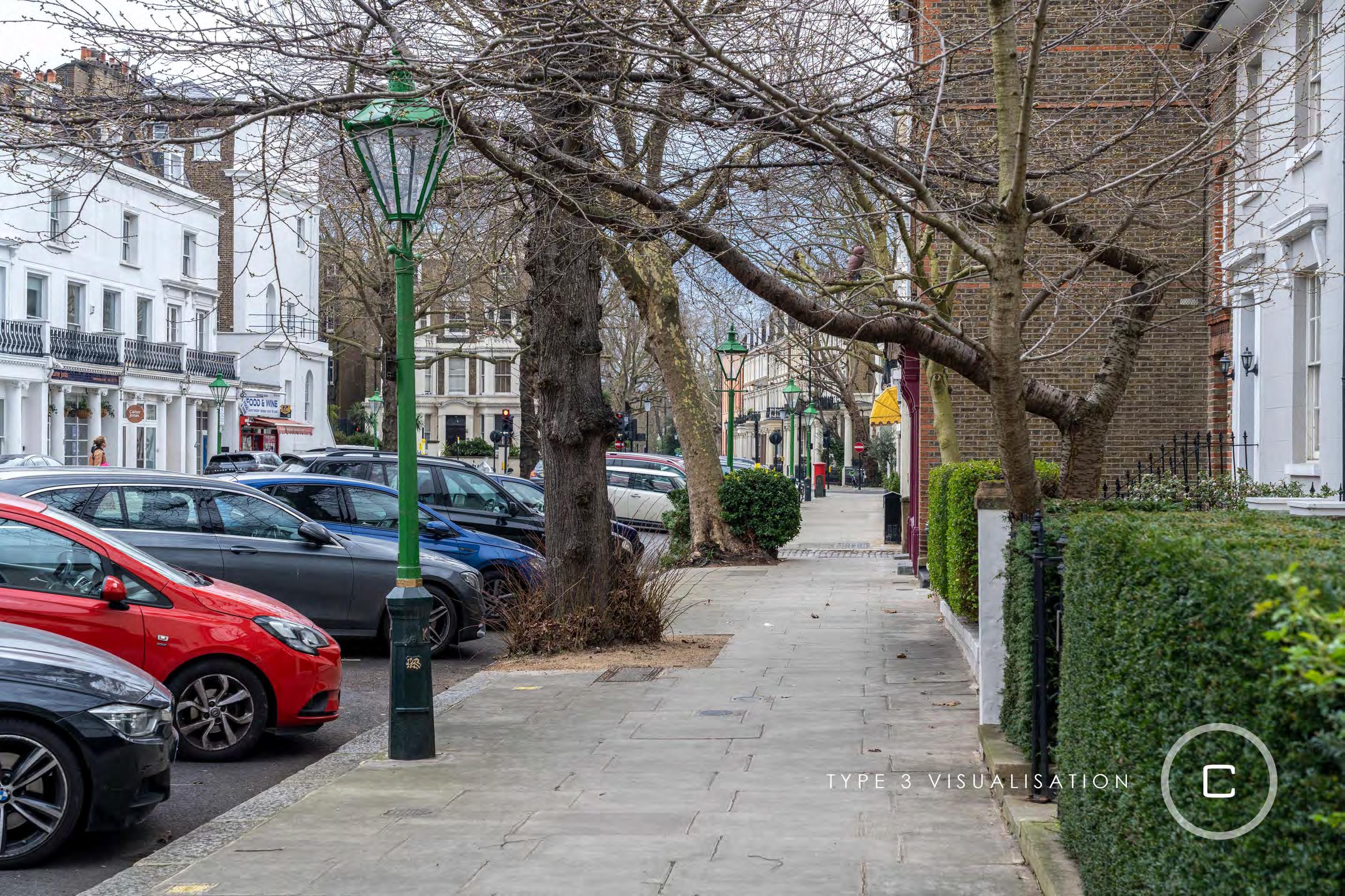
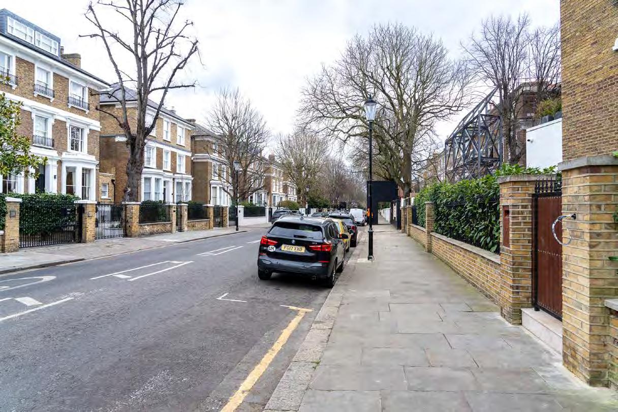
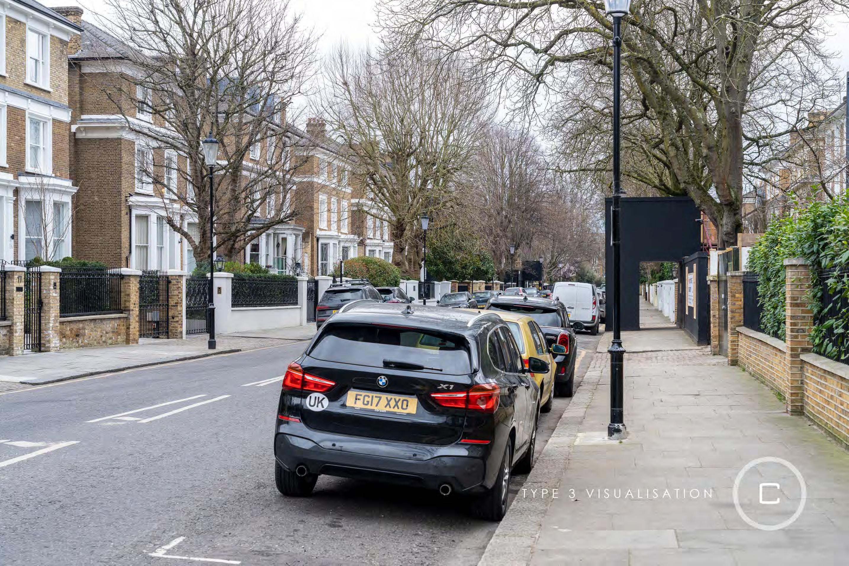
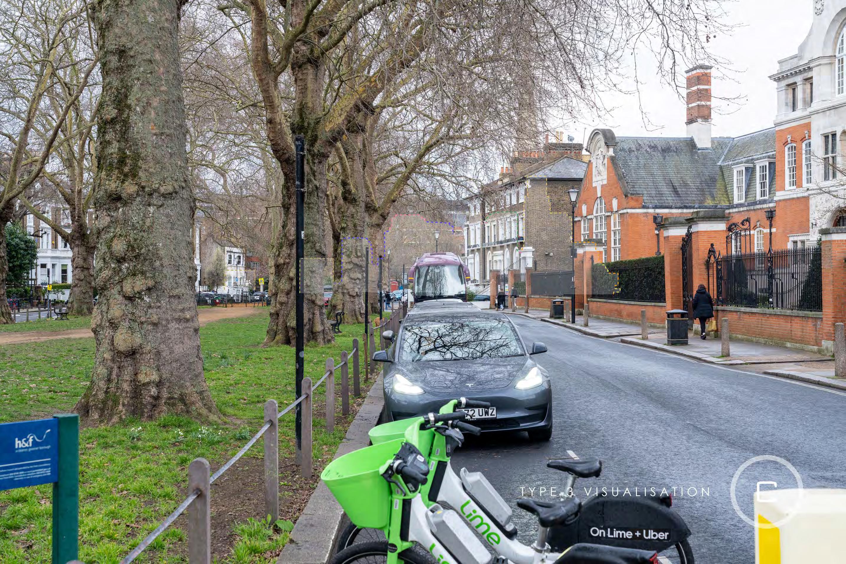
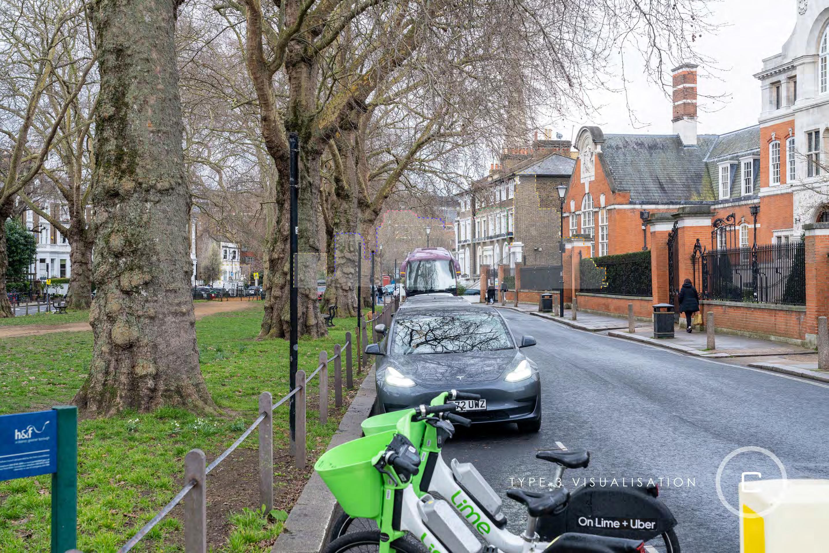
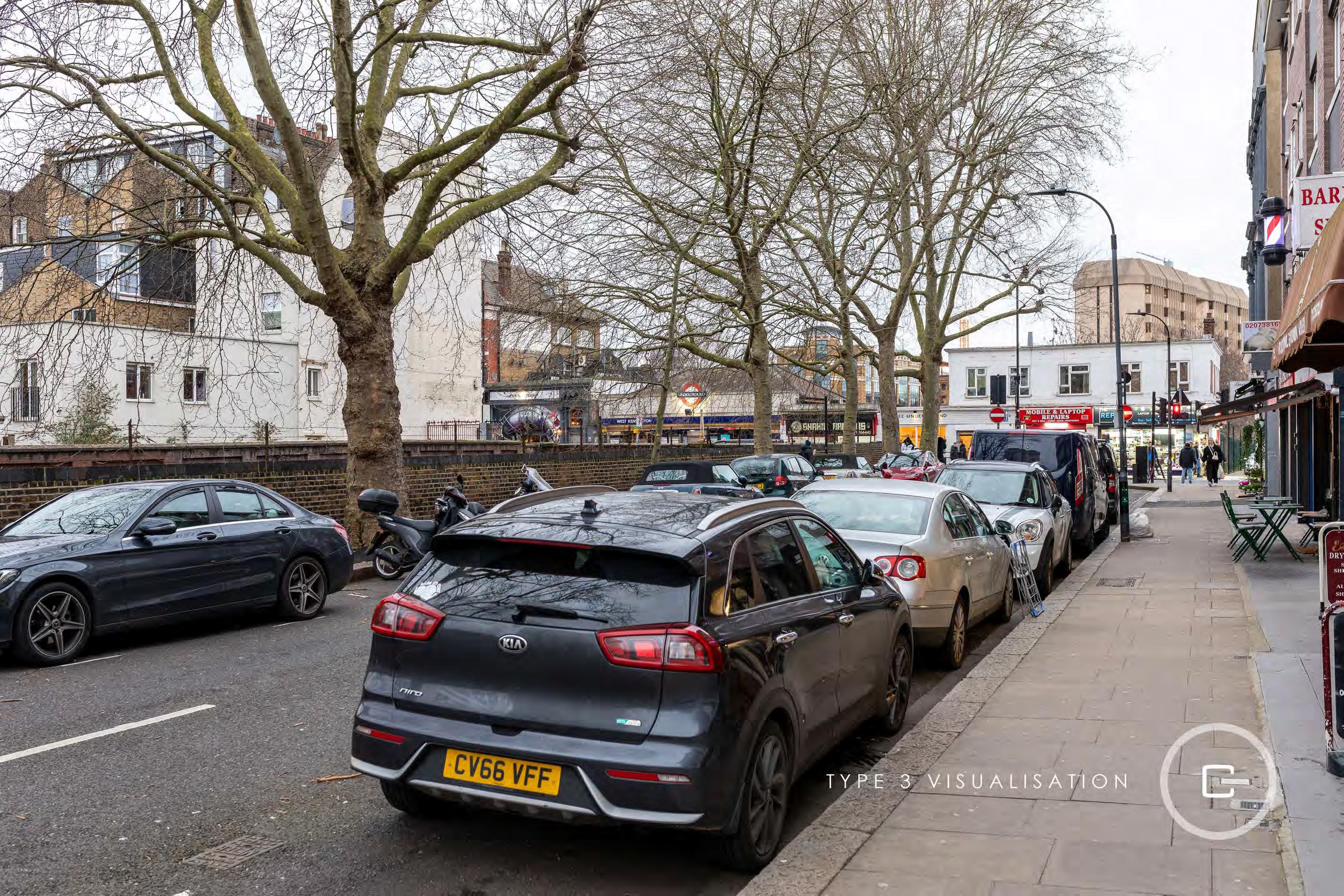
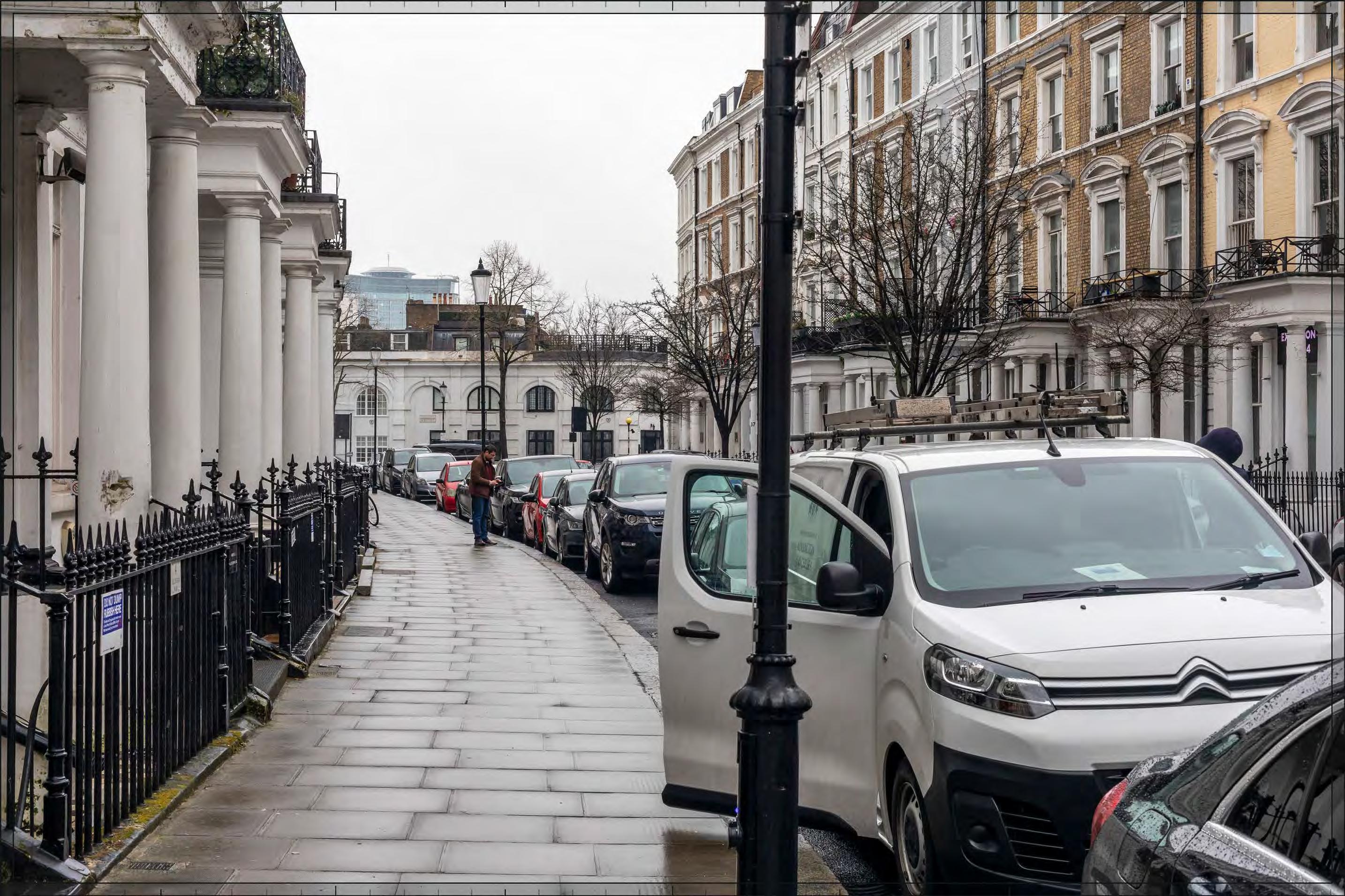
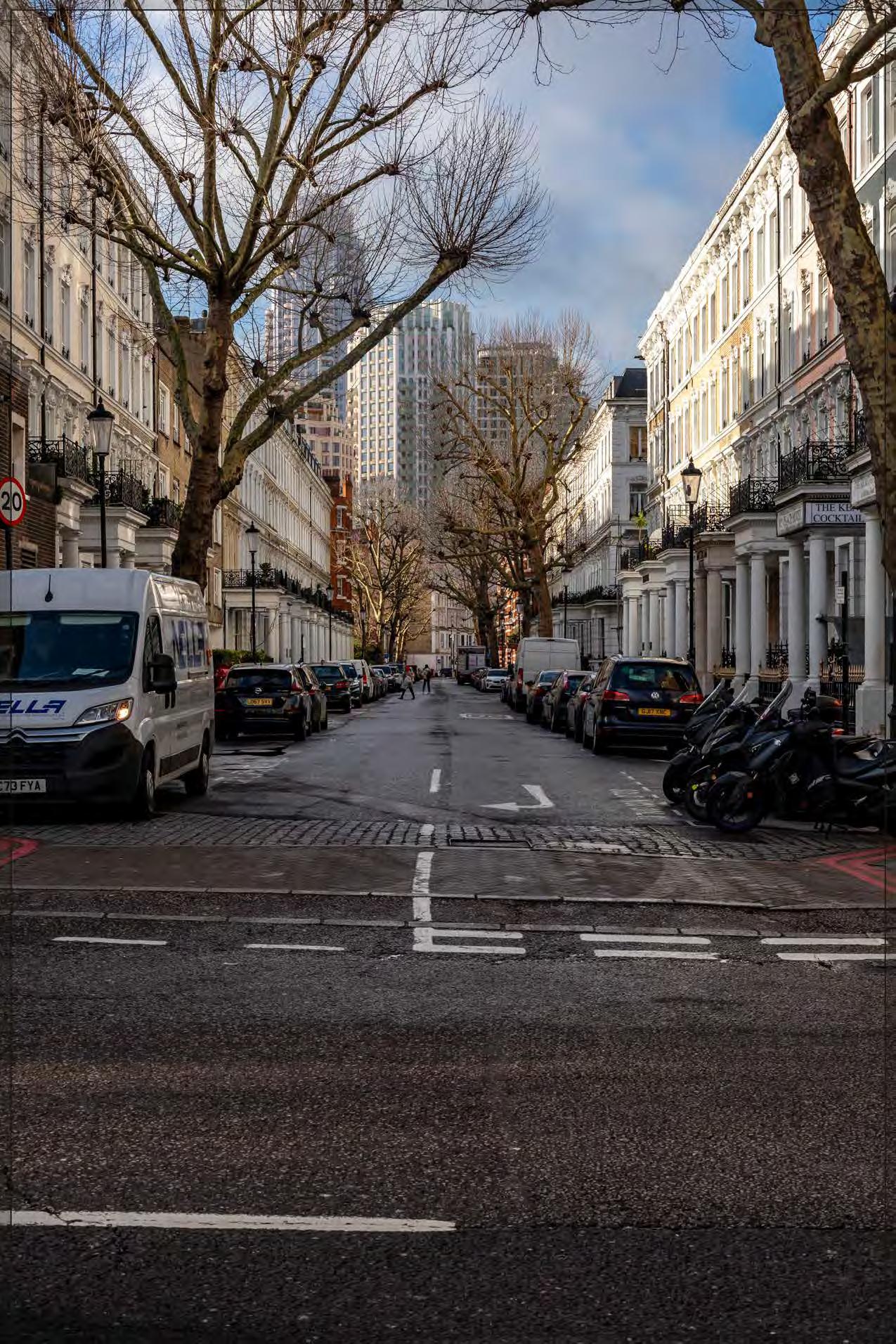
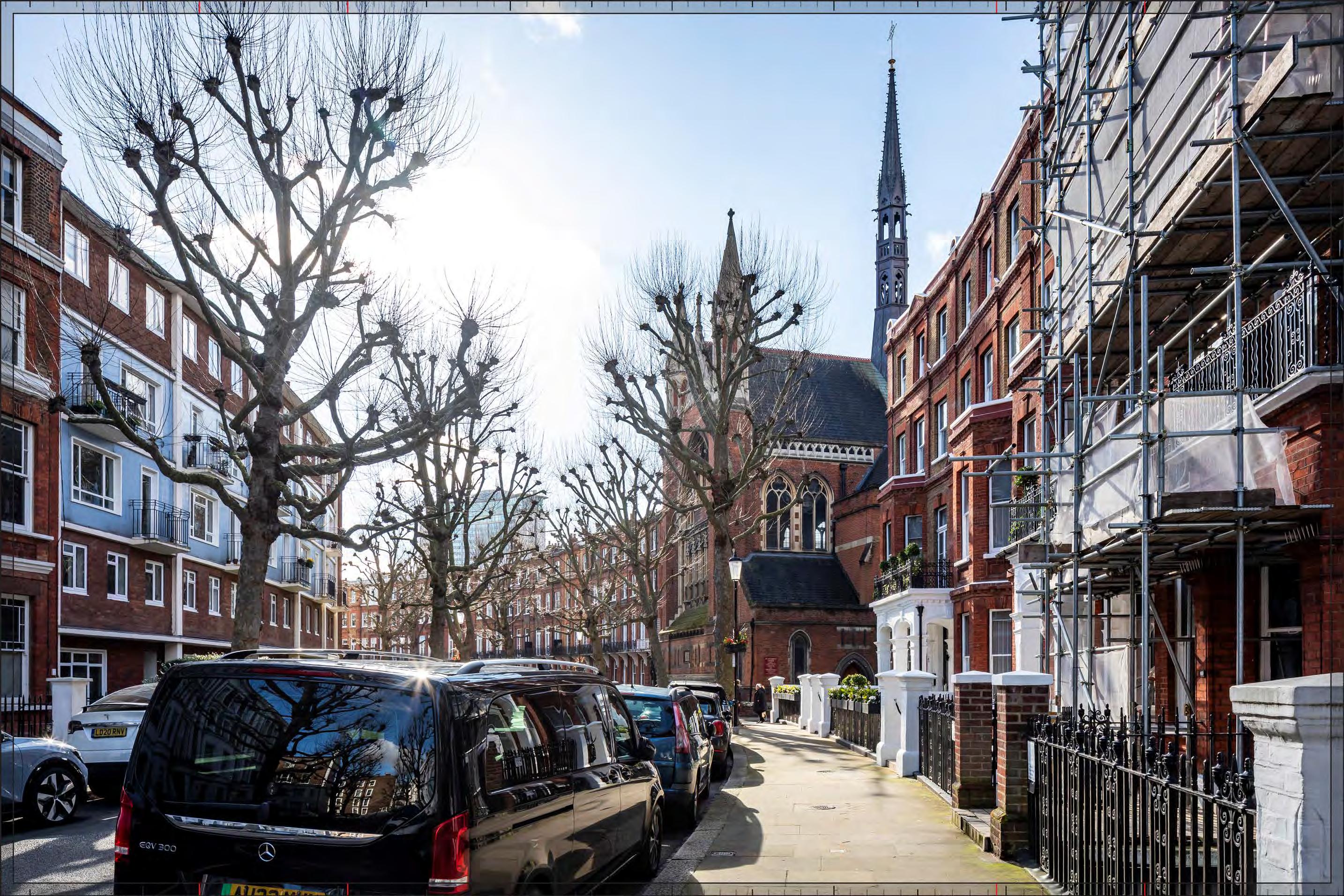
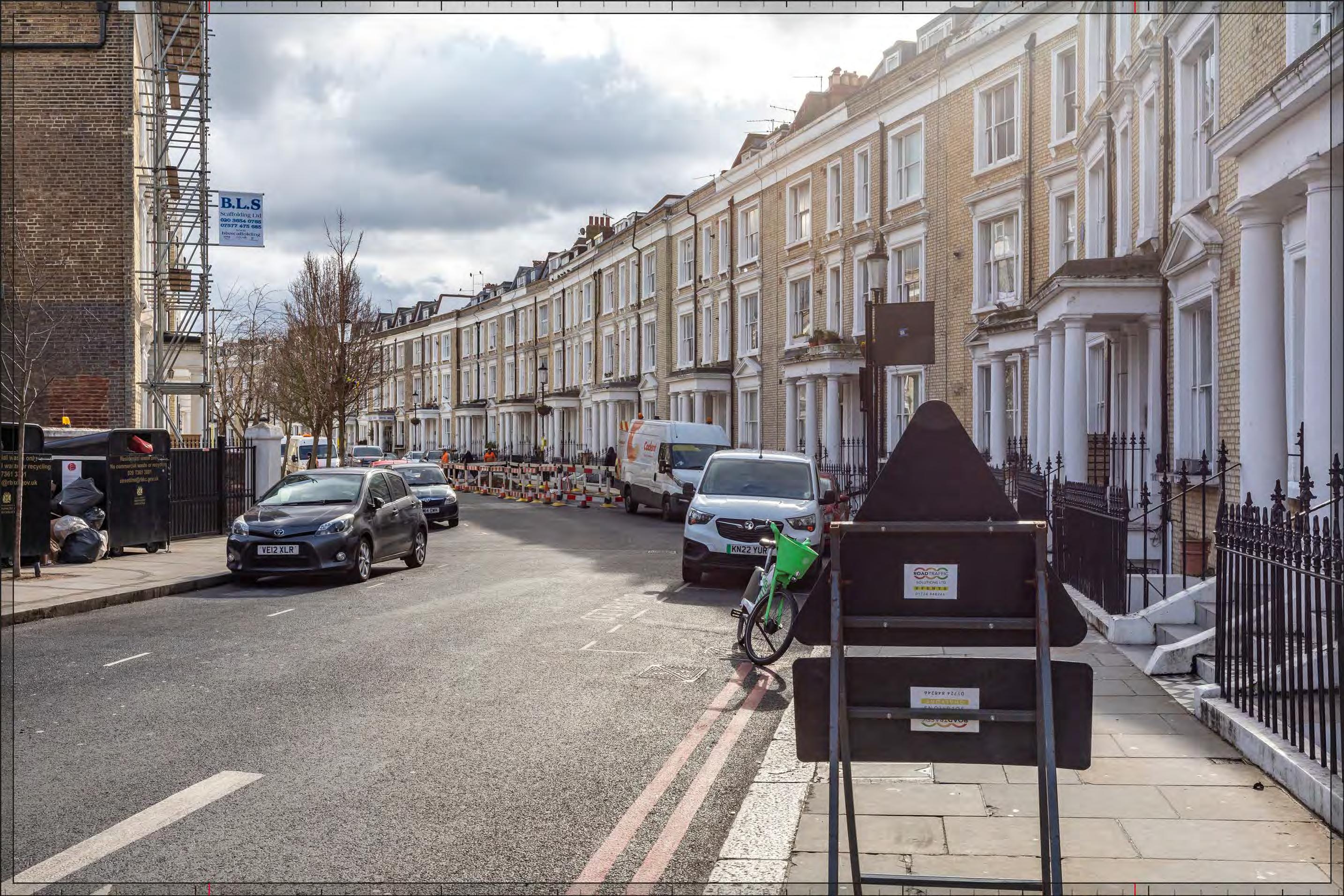
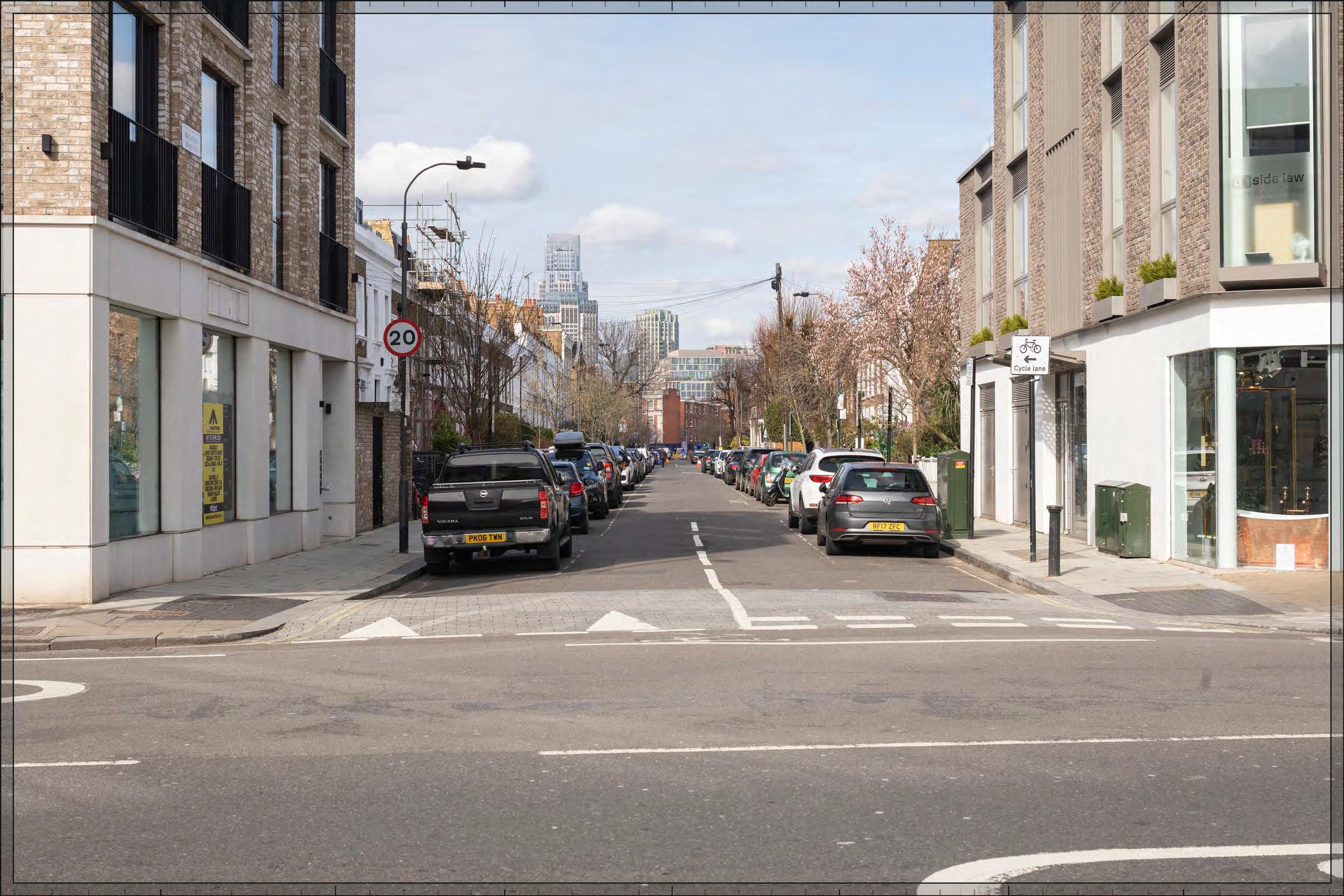
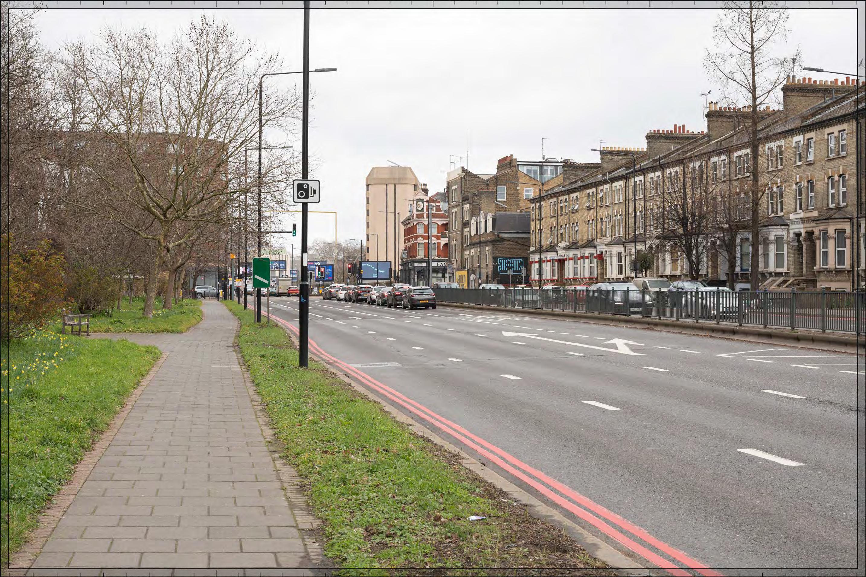
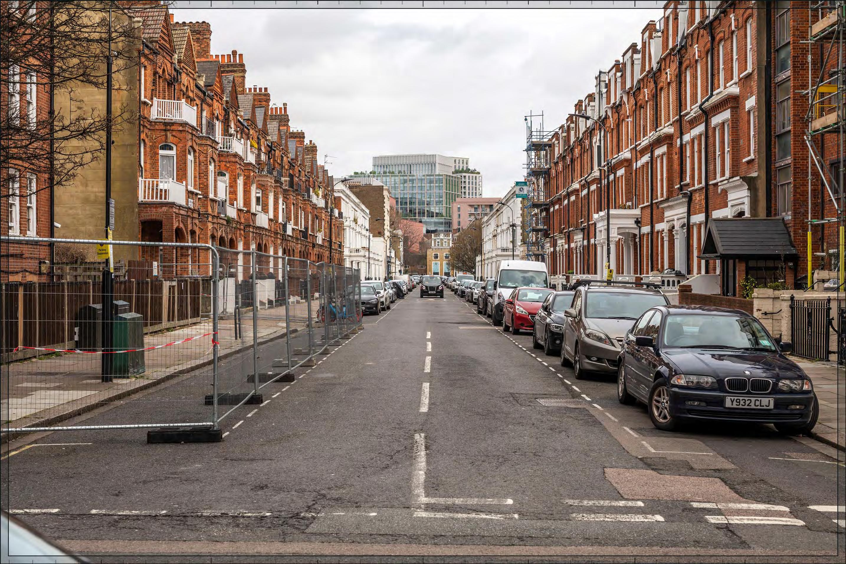
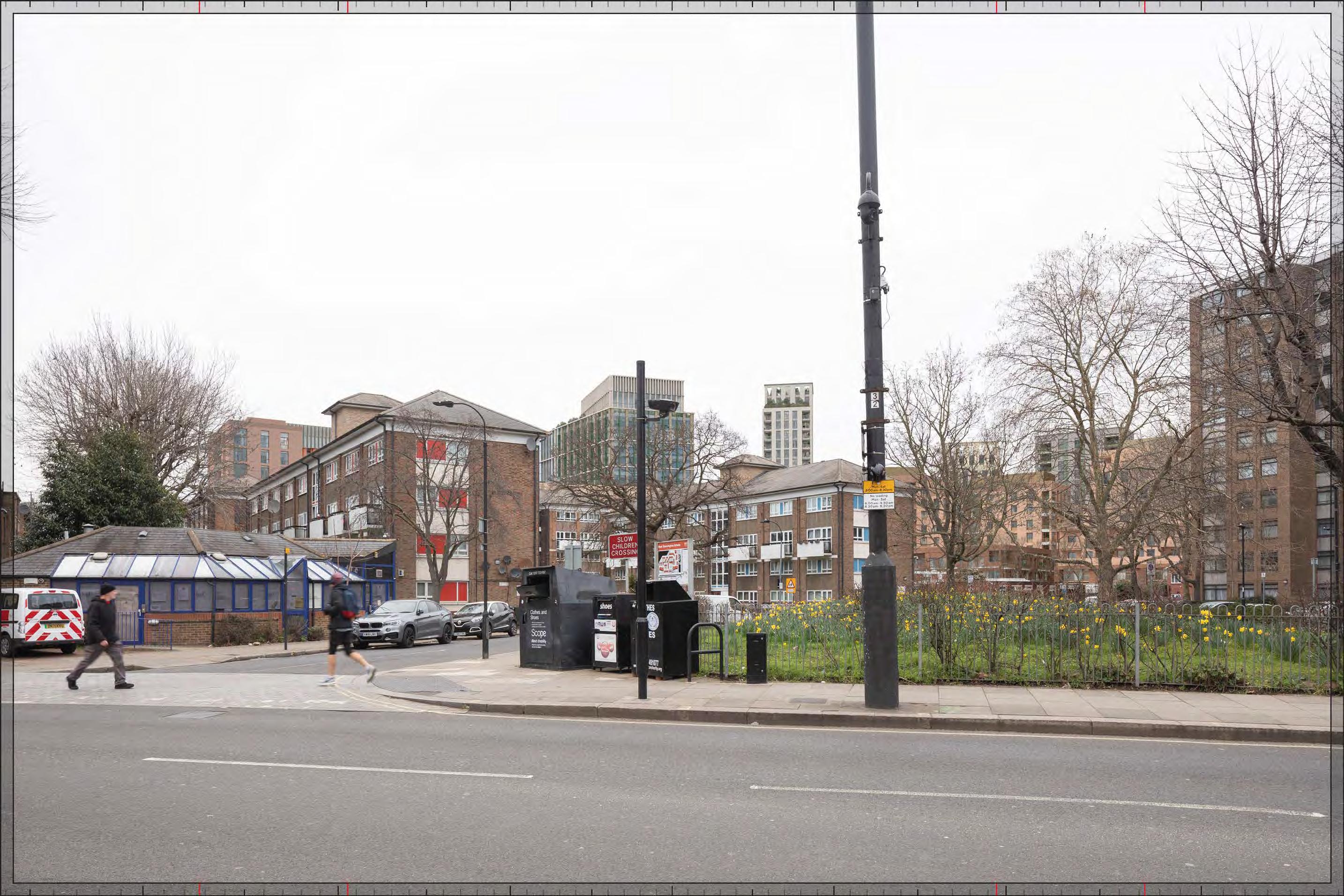
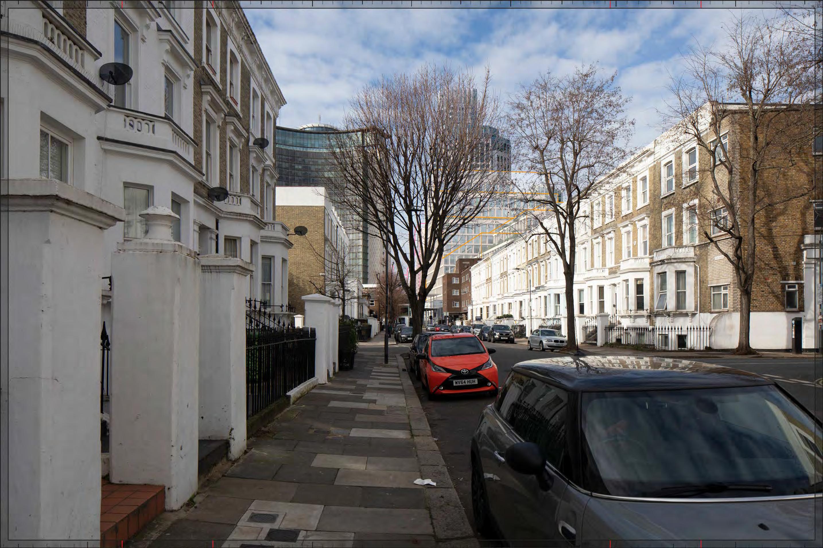
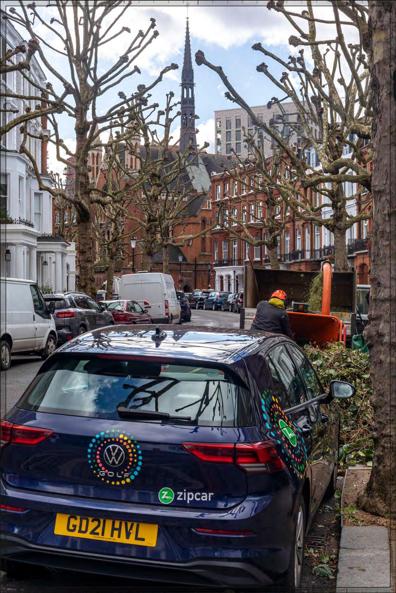
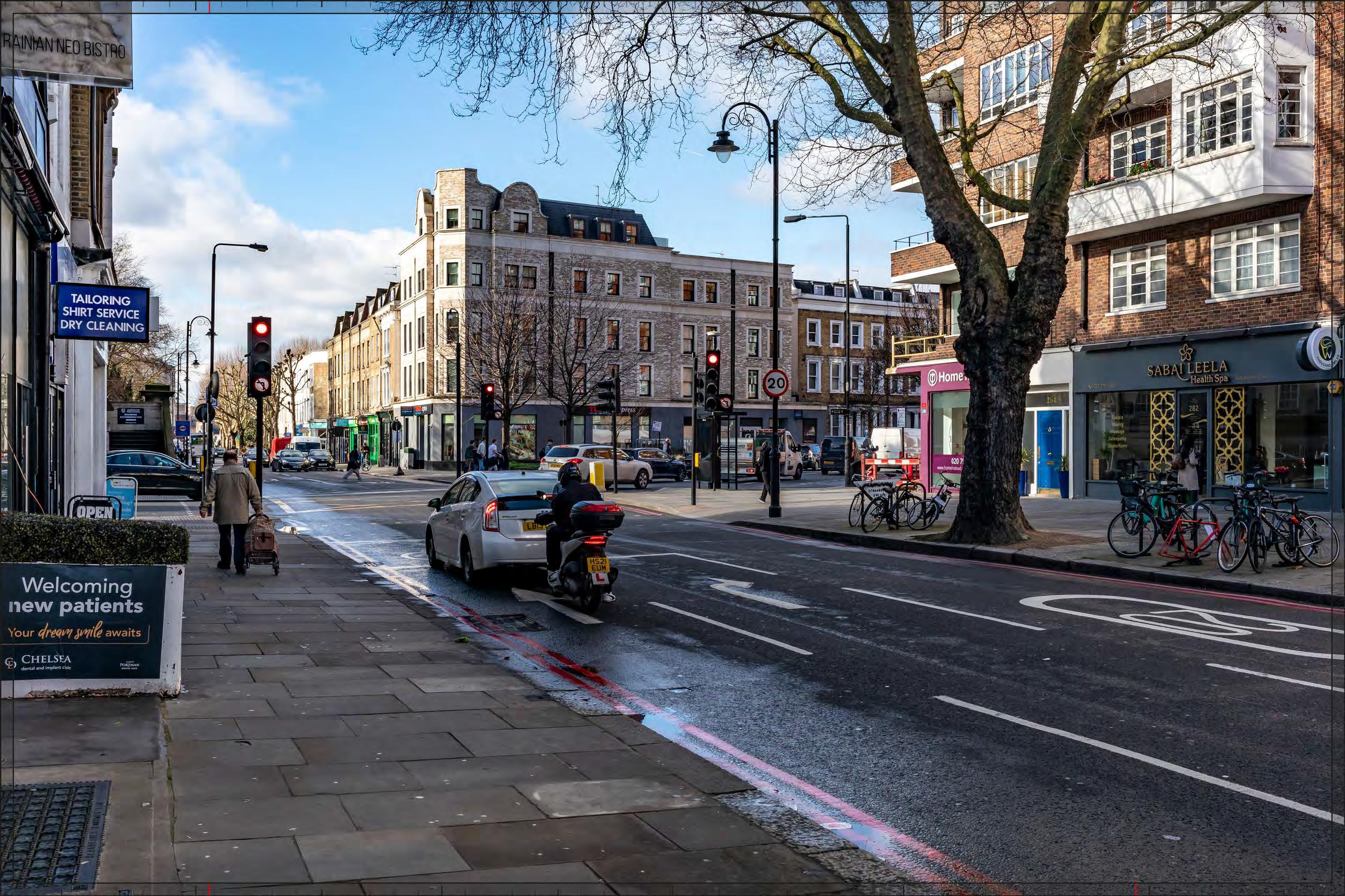
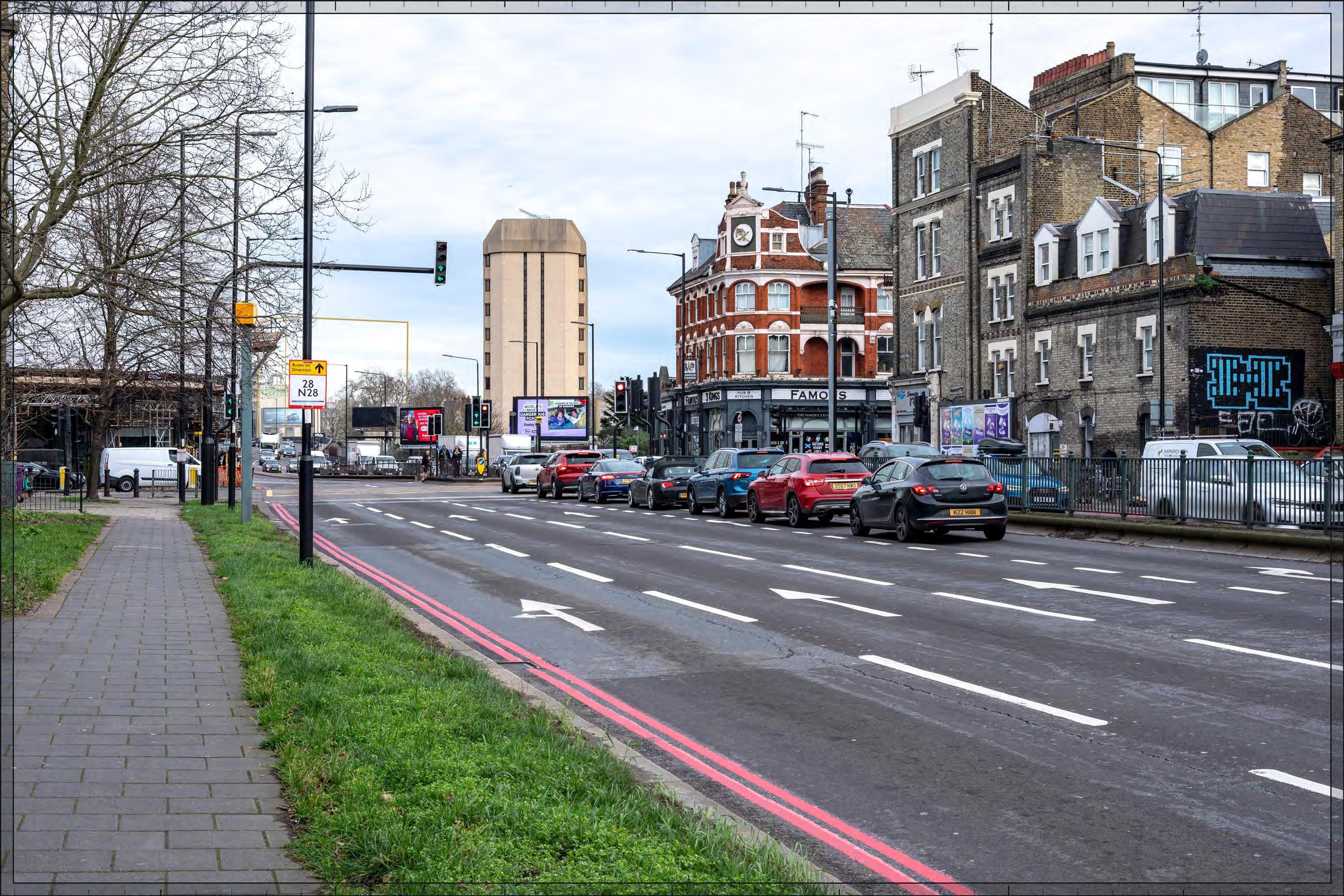
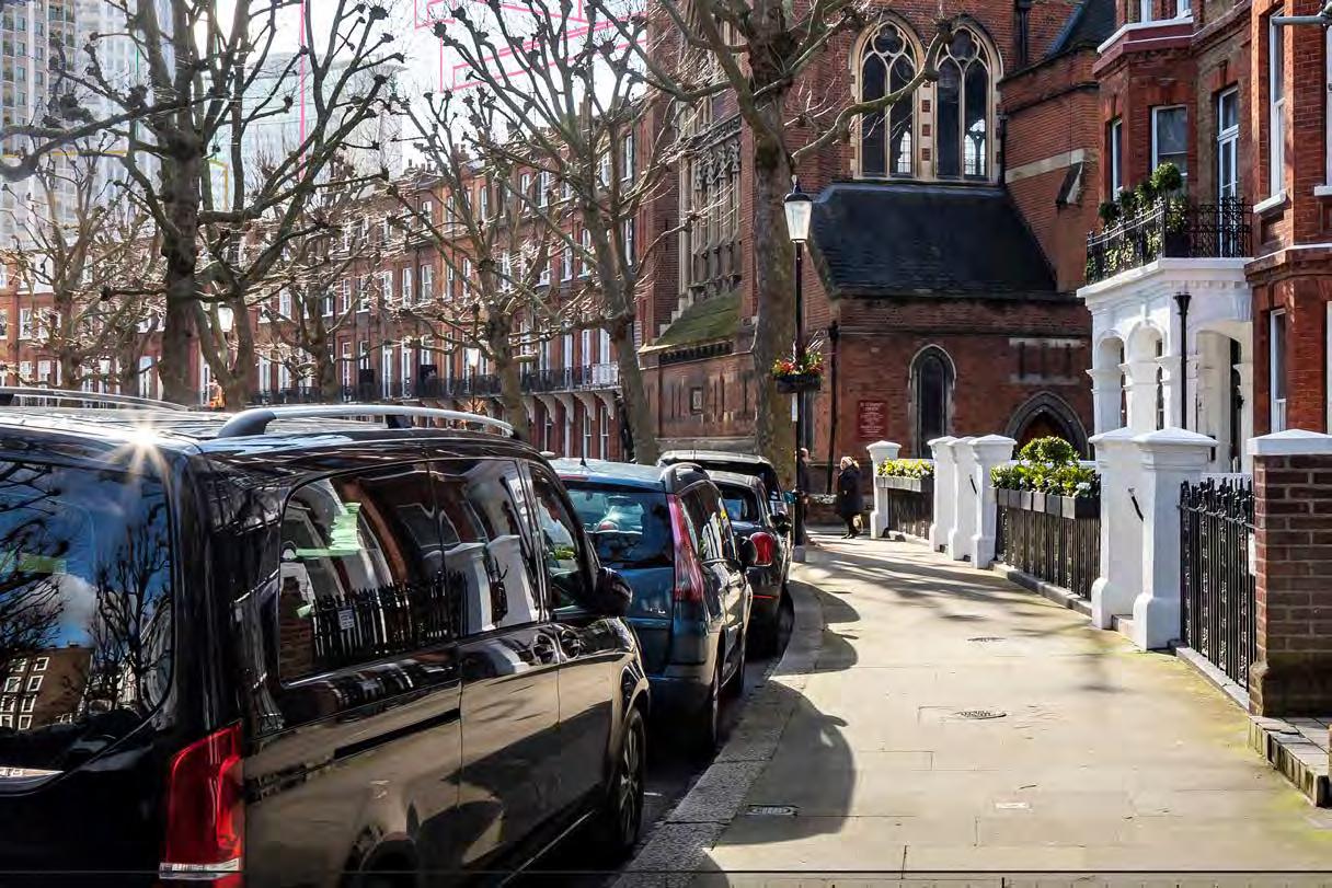
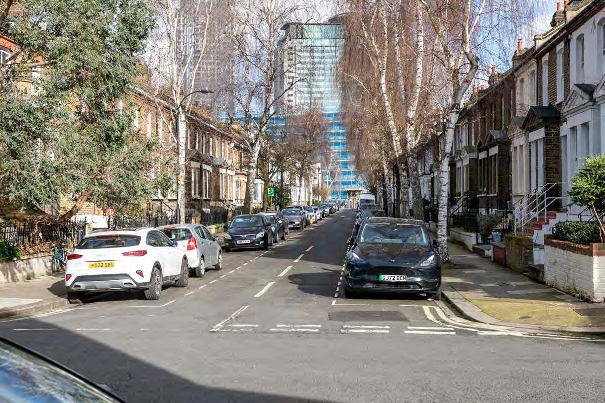
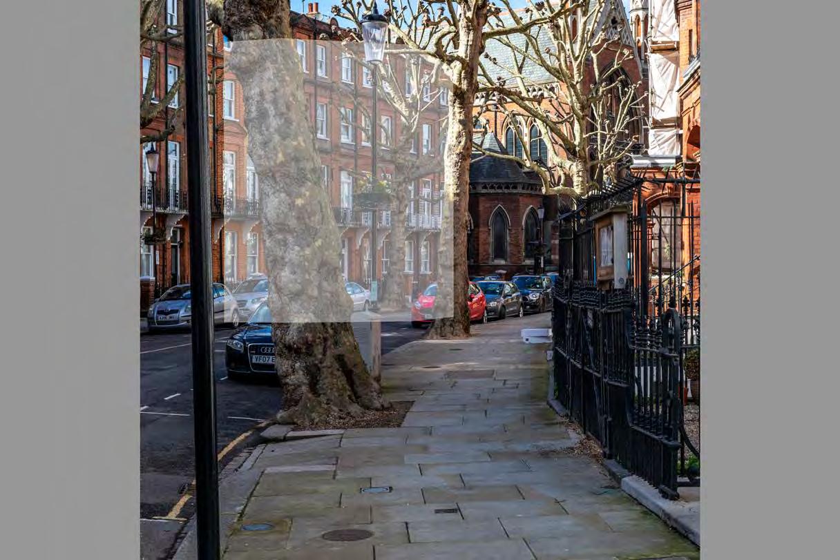
Mornington Avenue, west pavement, outside No.10
D28058 24mm 12/03/23 / 15:41
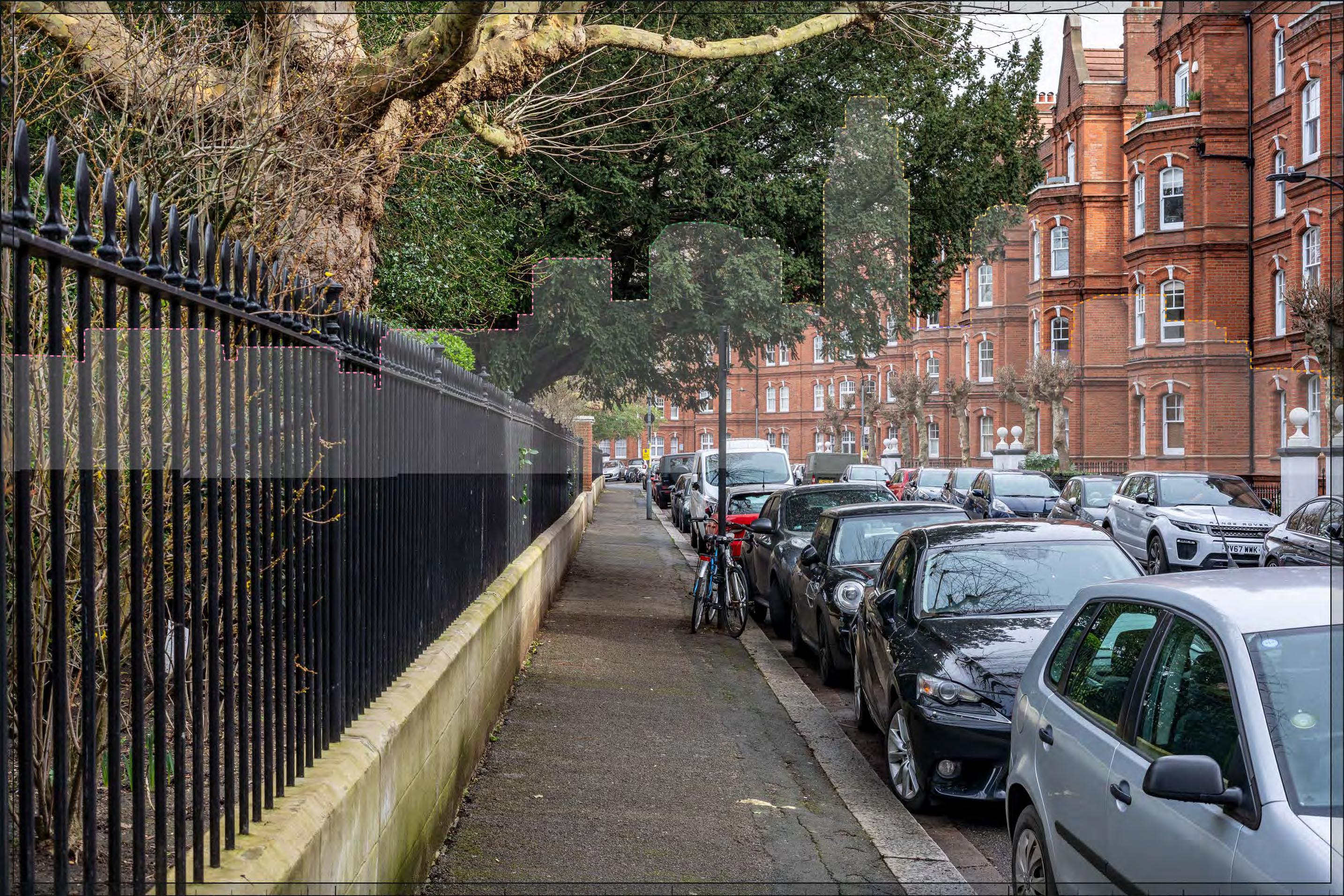
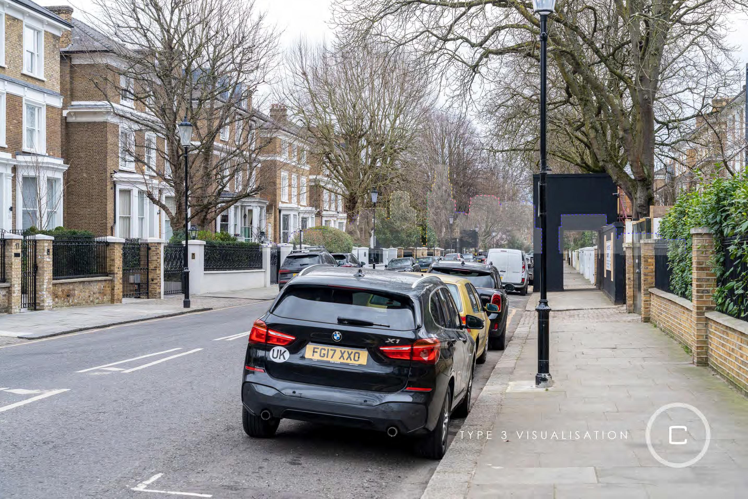
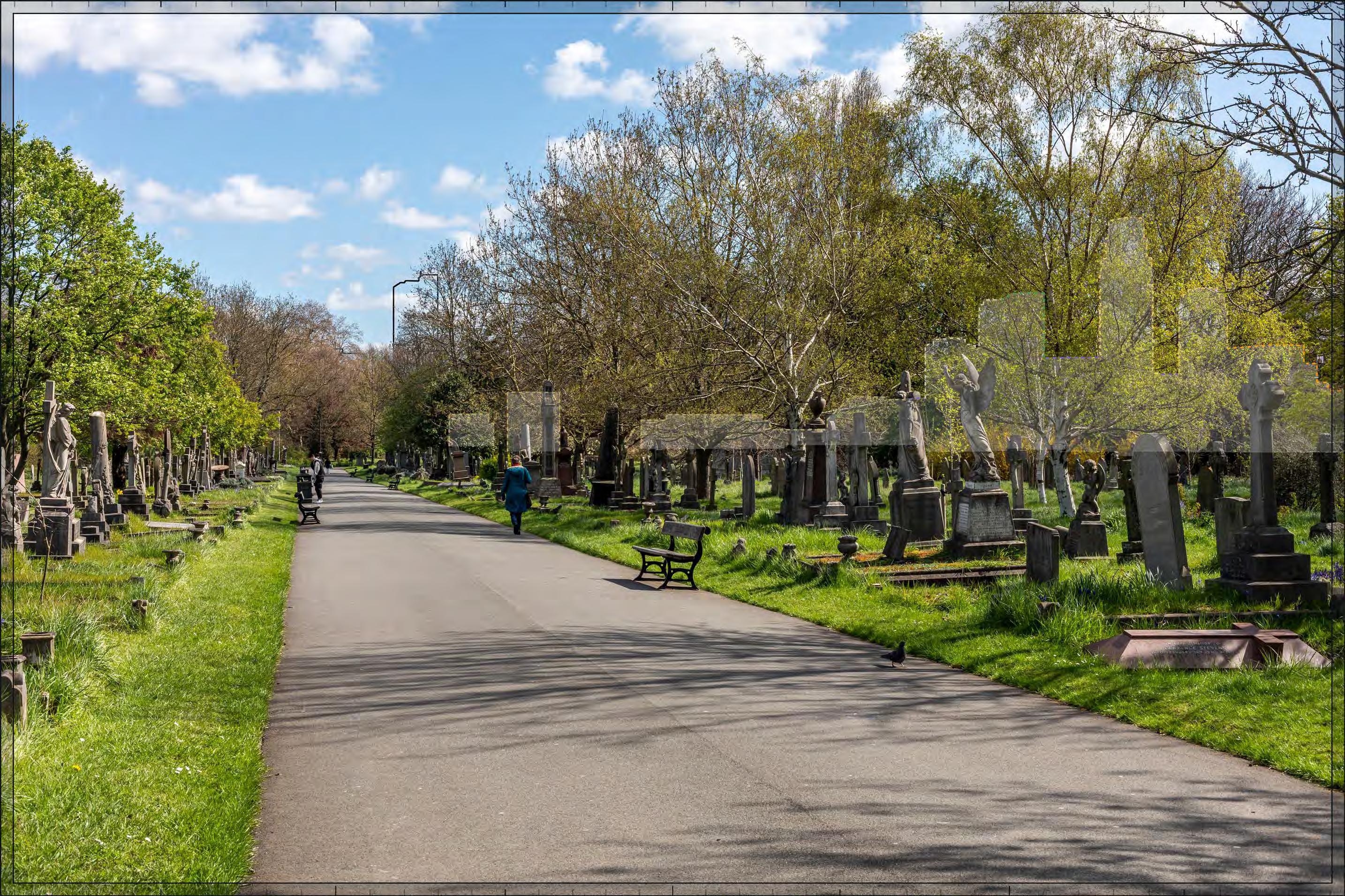
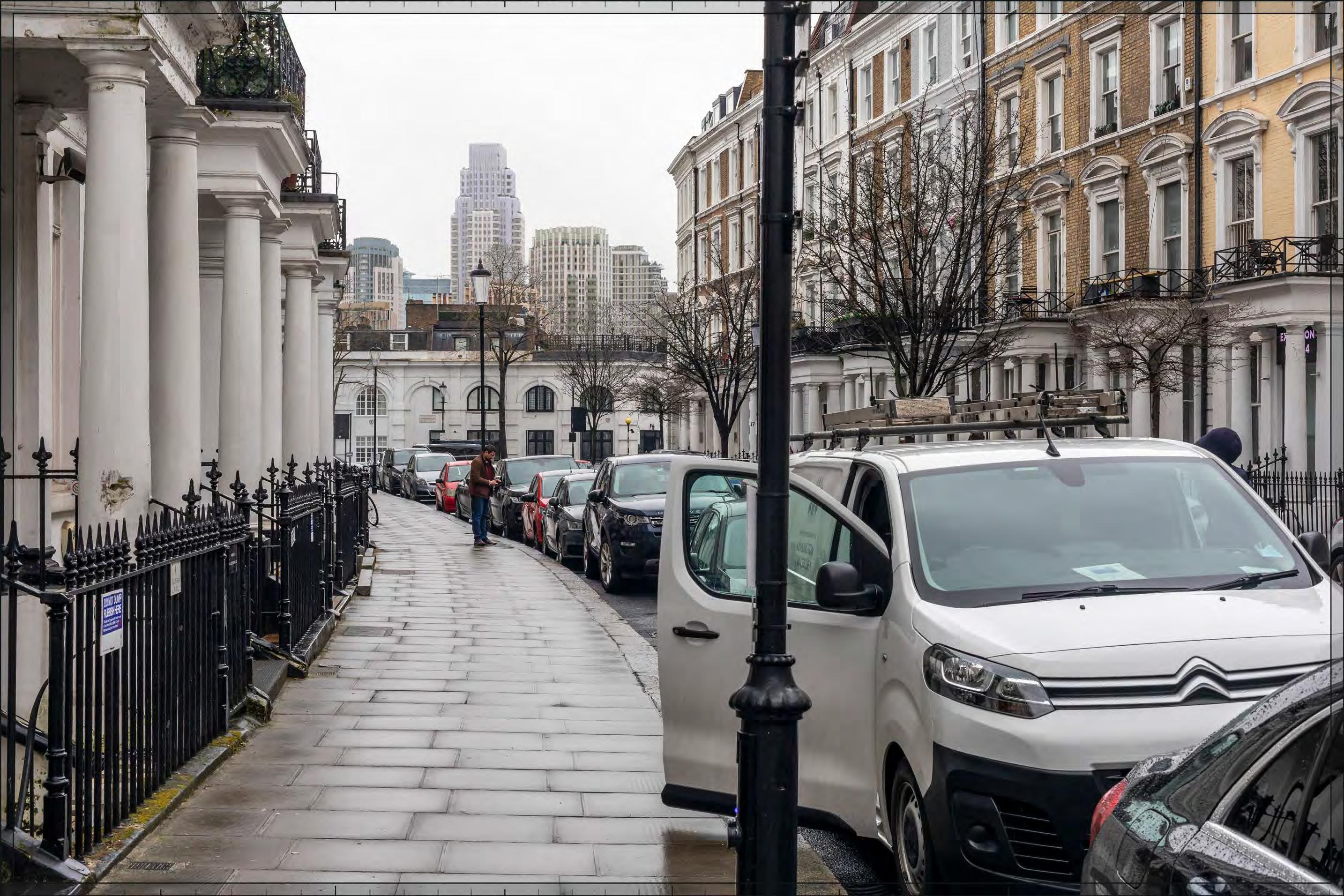
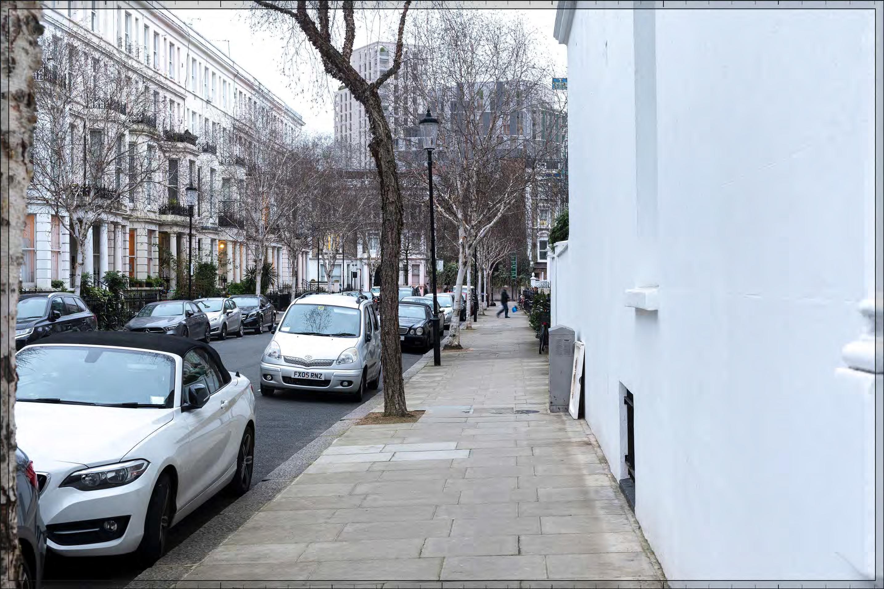
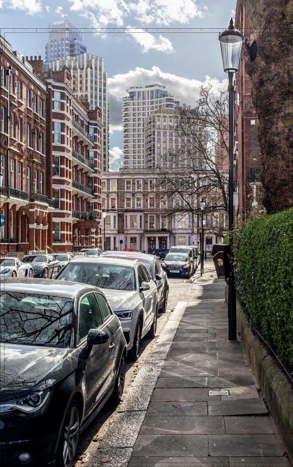
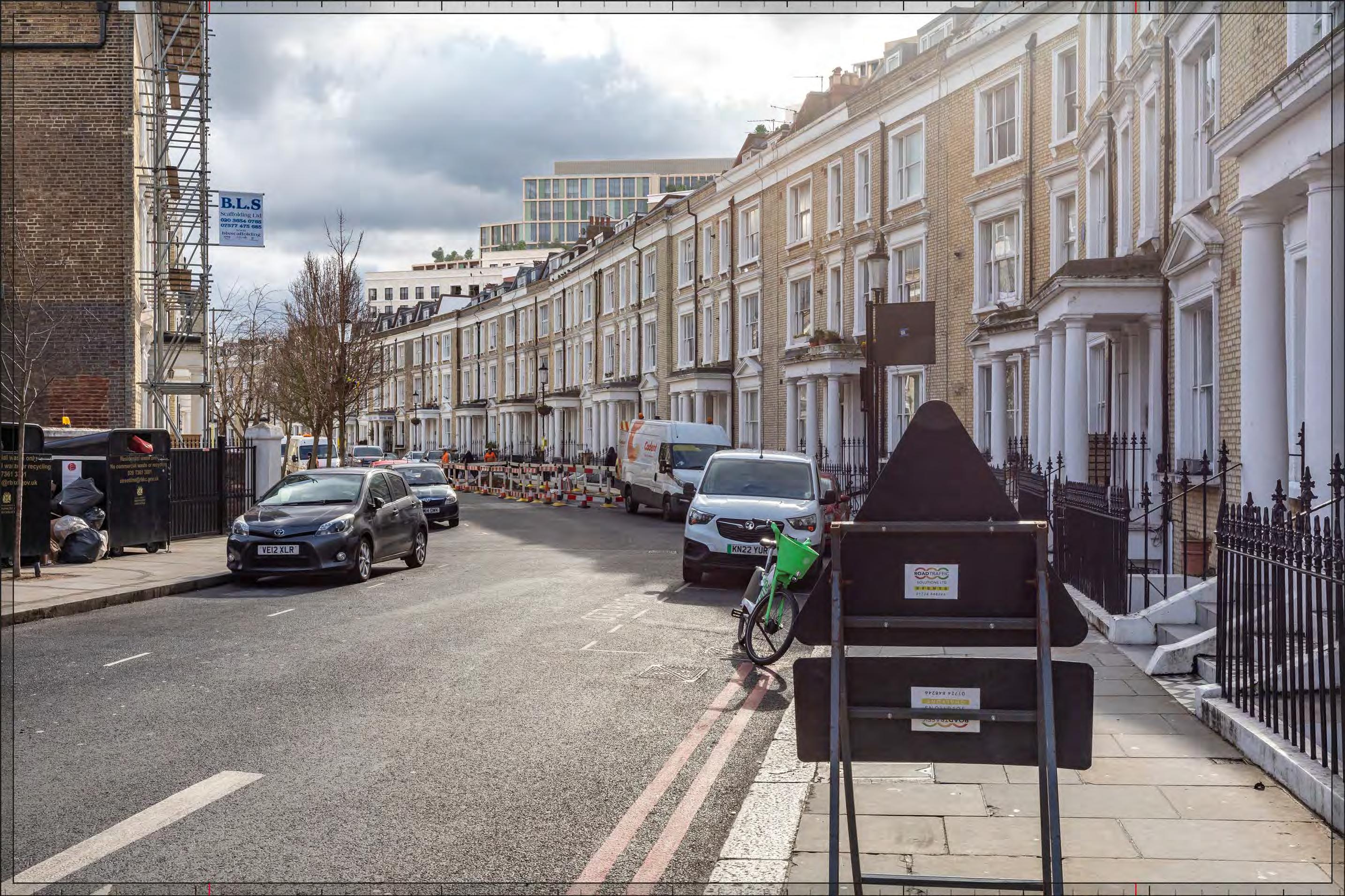
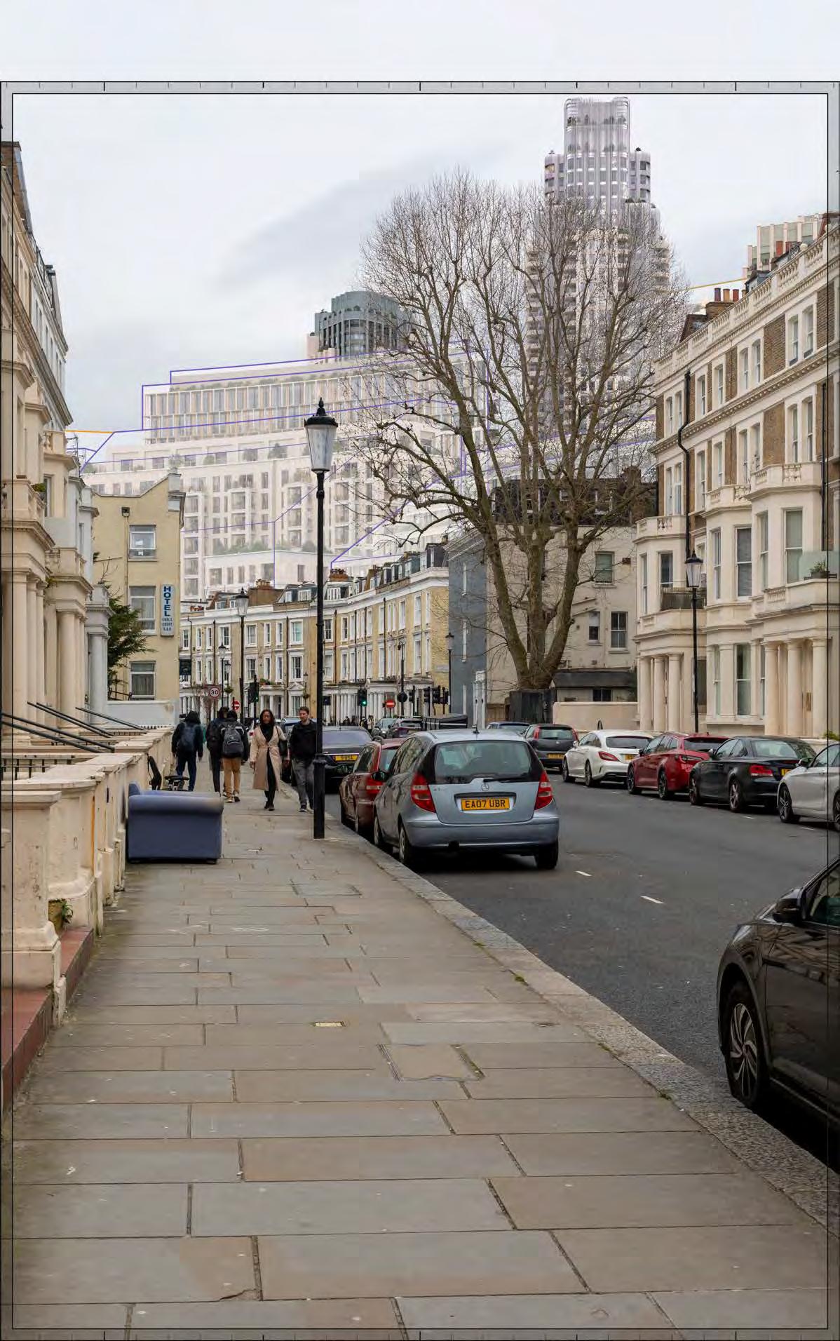
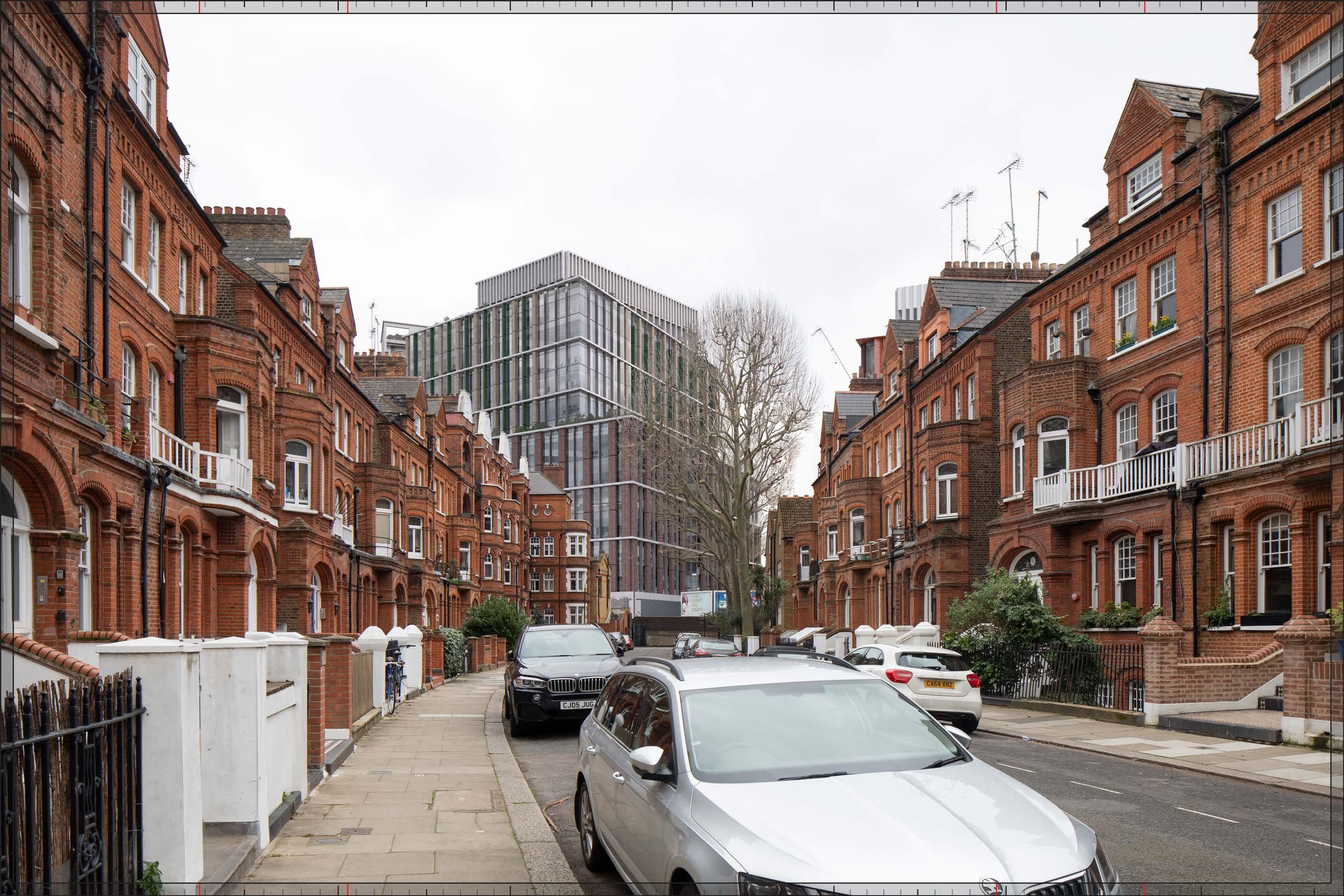
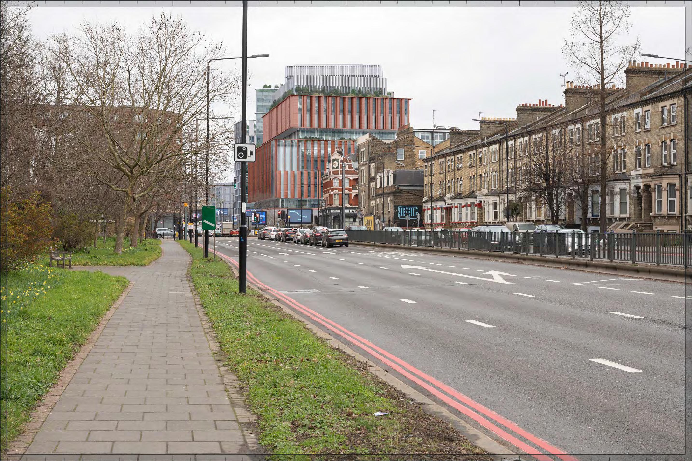
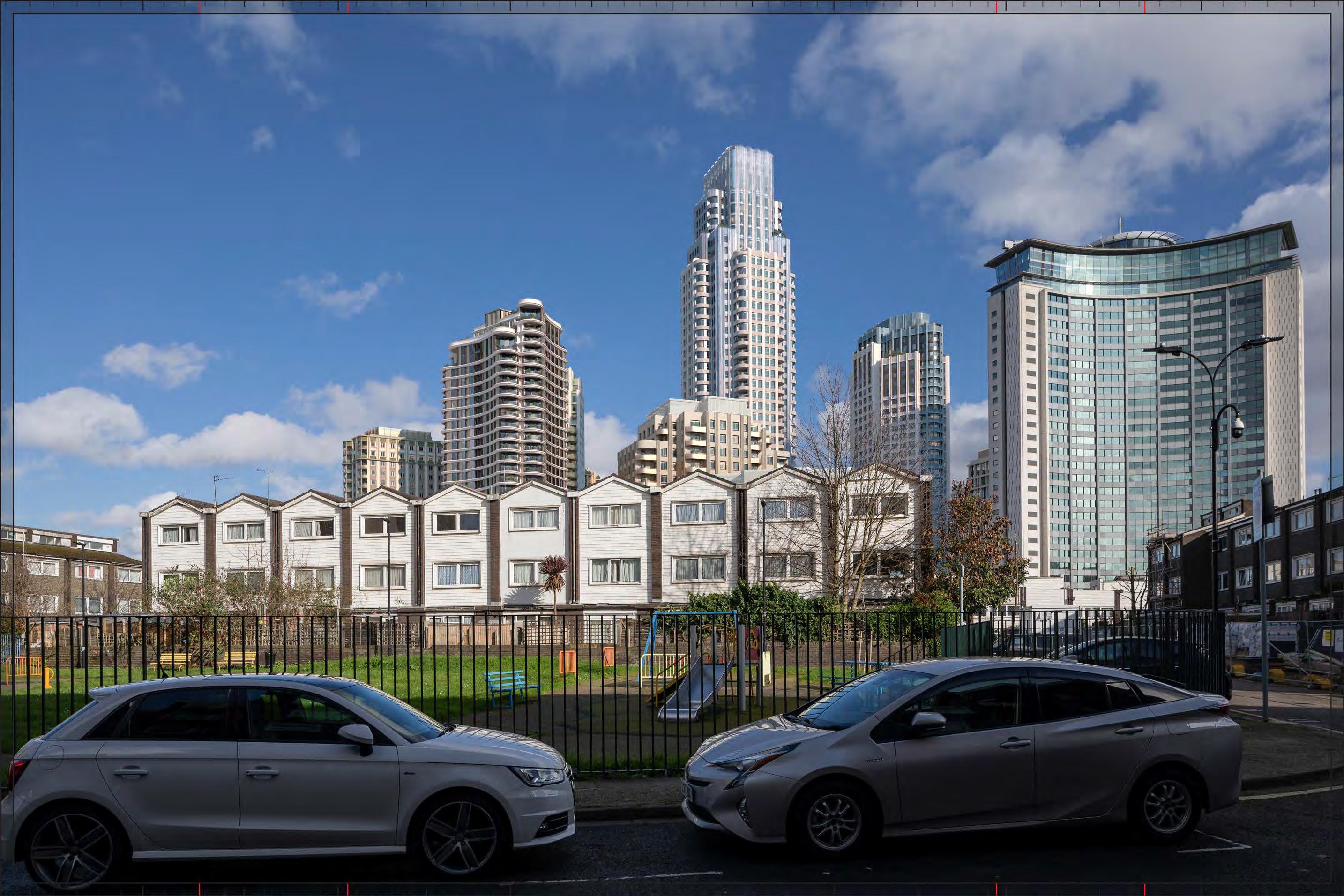
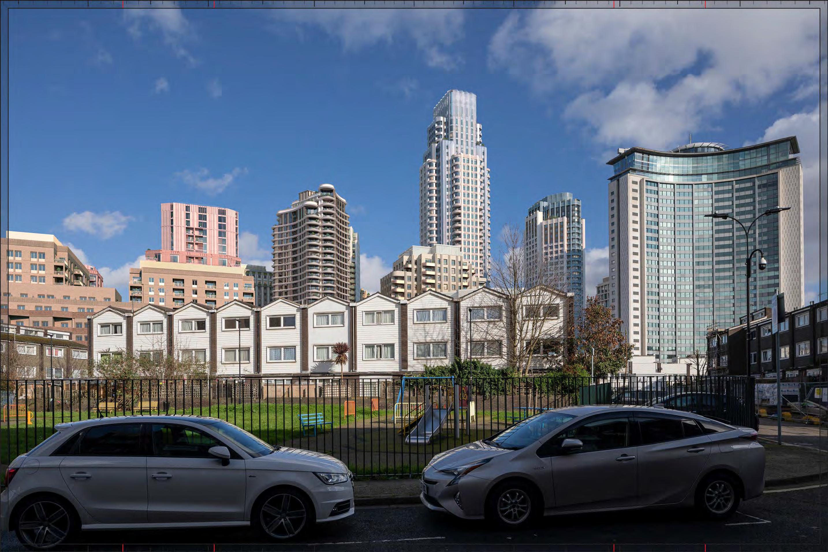
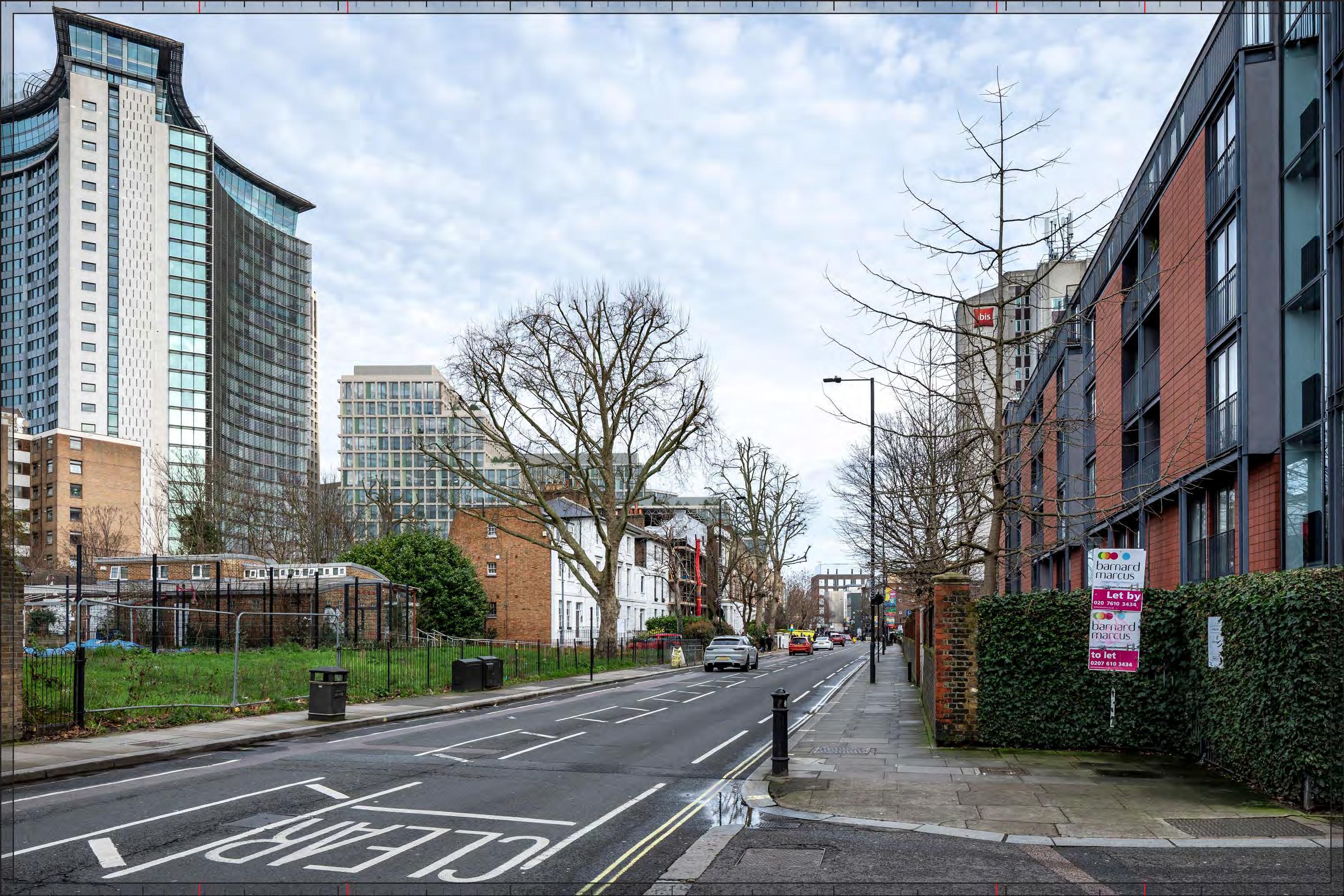
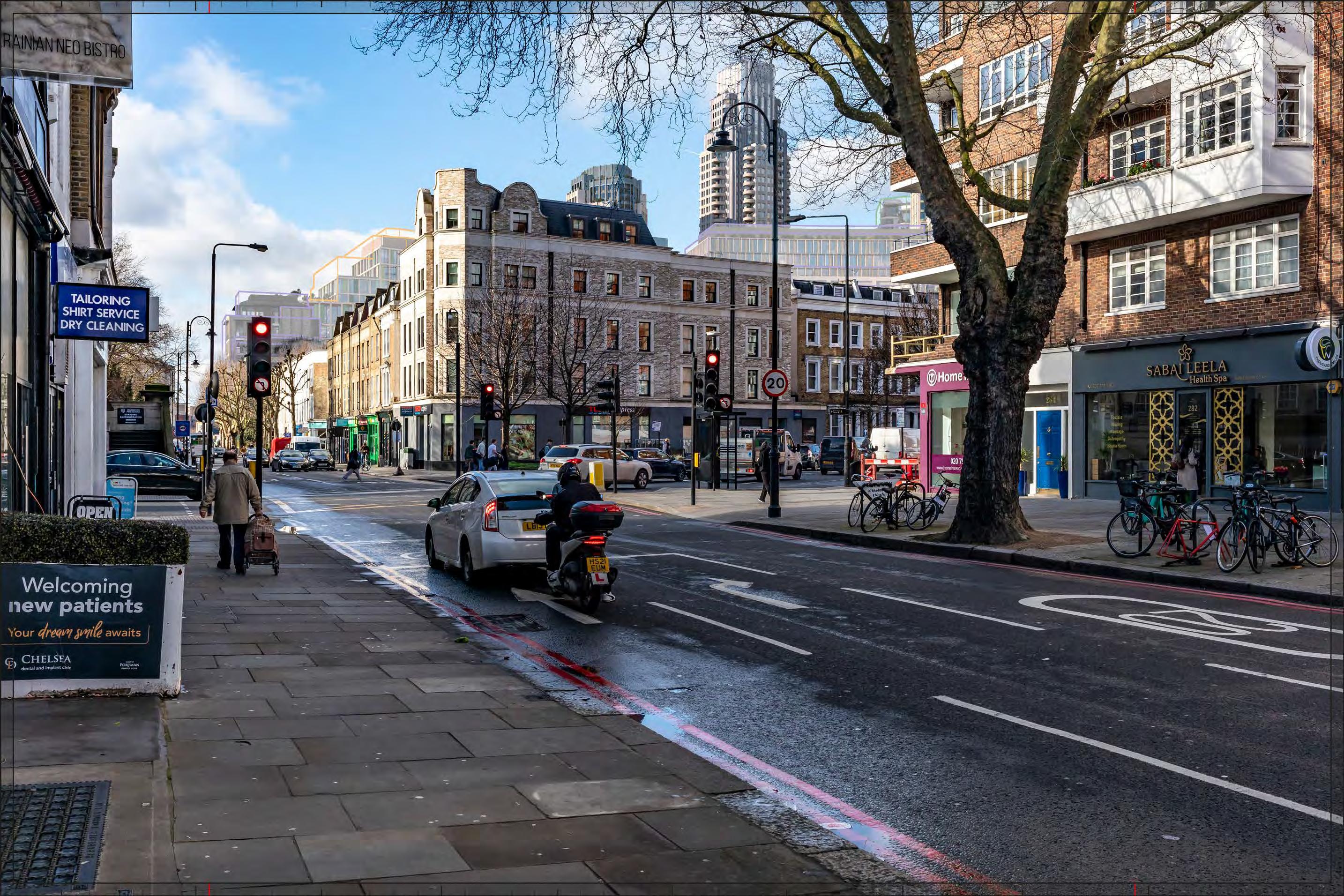
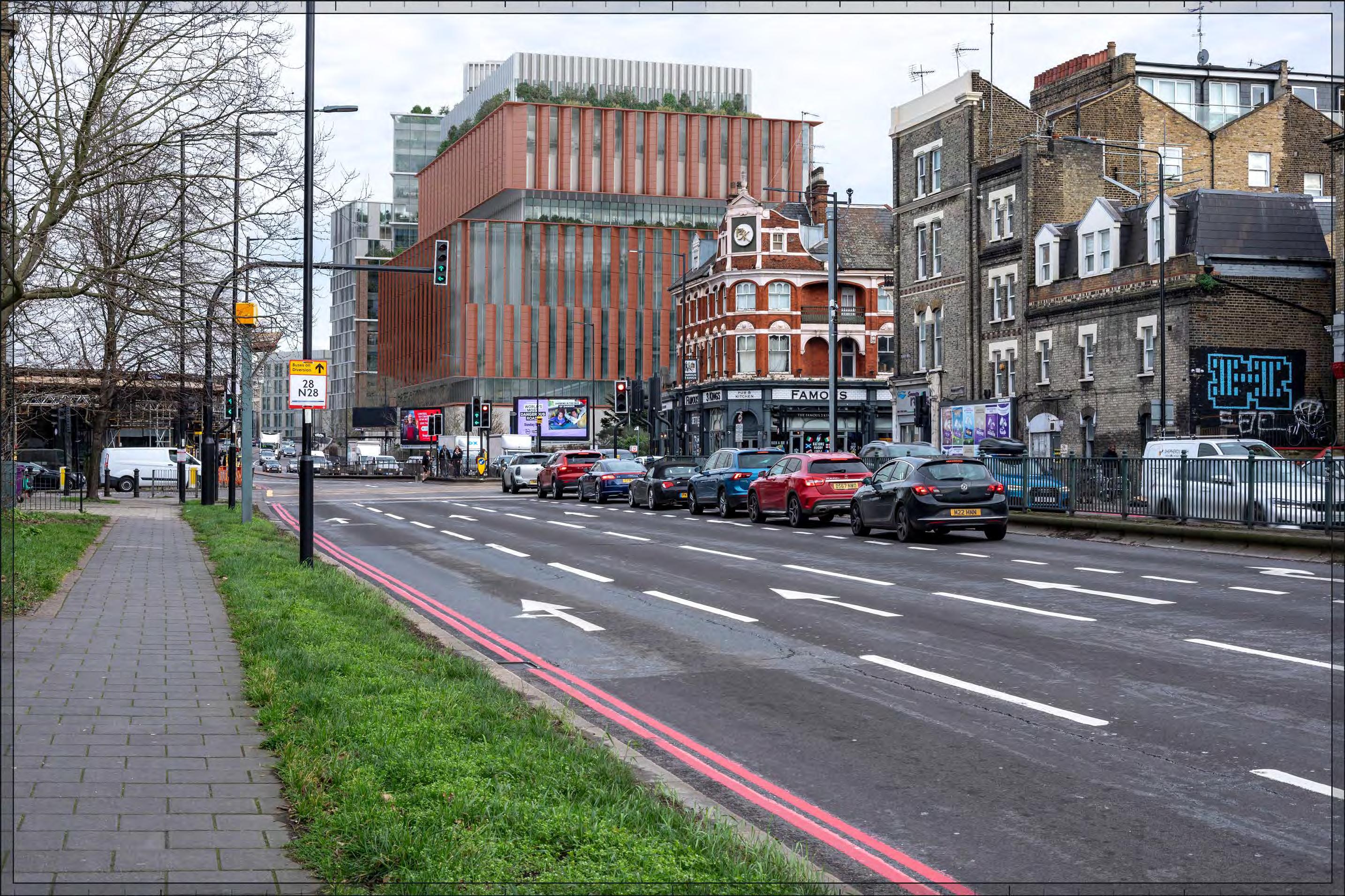
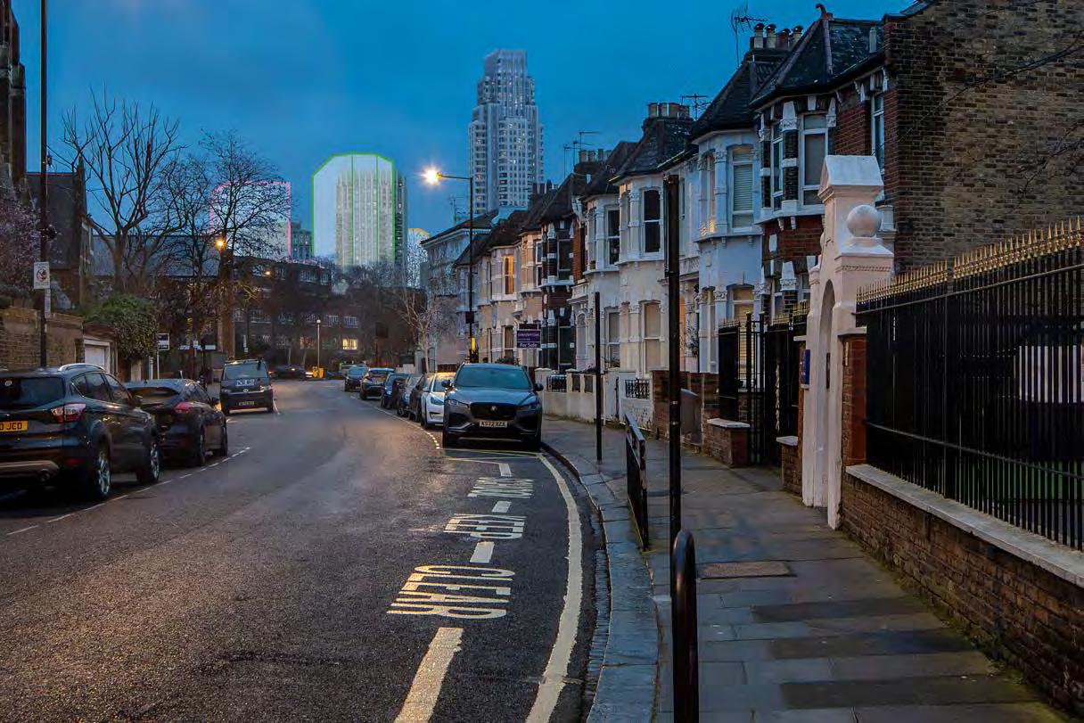
Proposed illustrative render of Outline Component, Early Phases
Mornington Avenue, west pavement, outside No.10
D28058 24mm 12/03/23 / 15:41
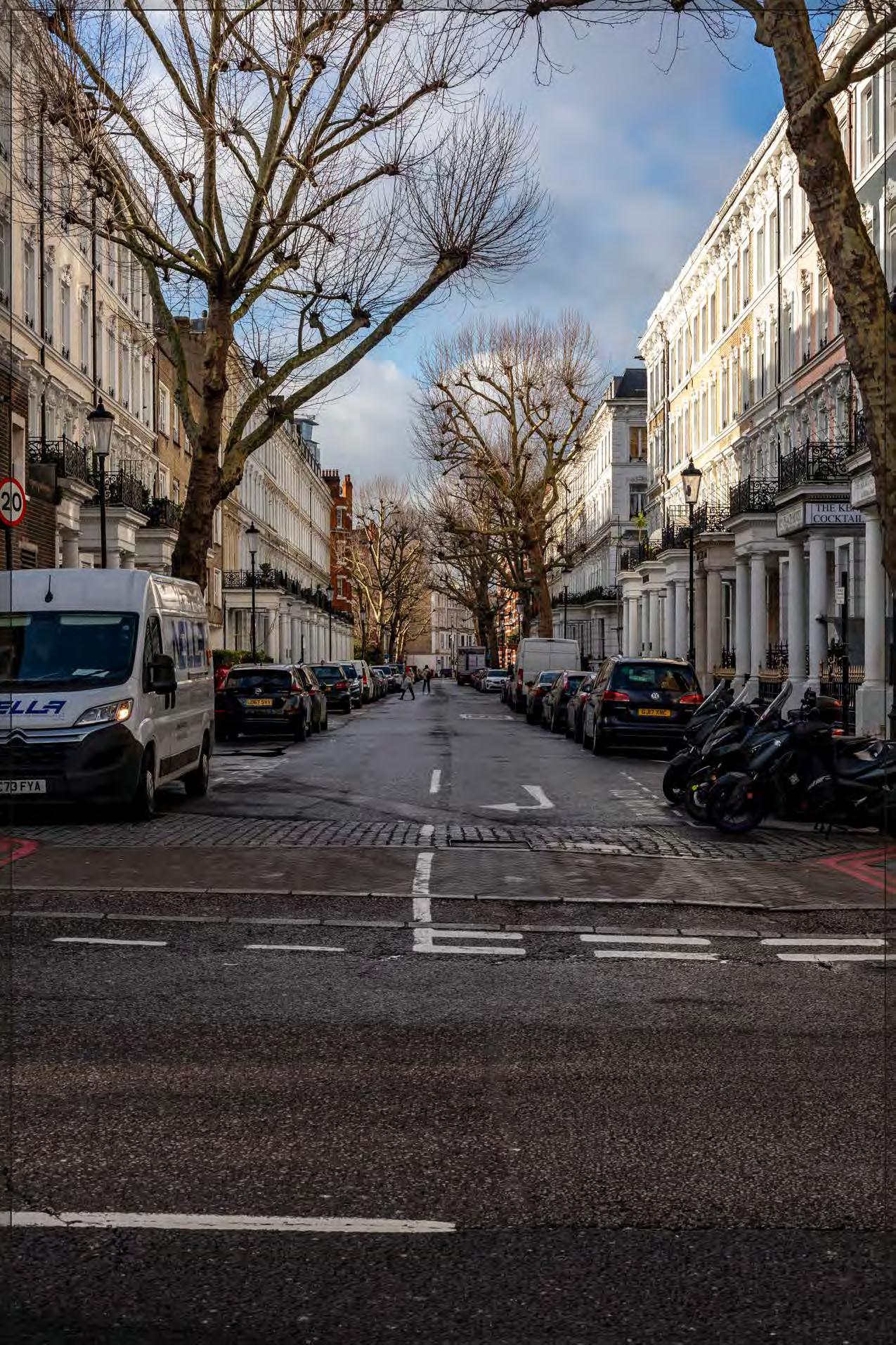
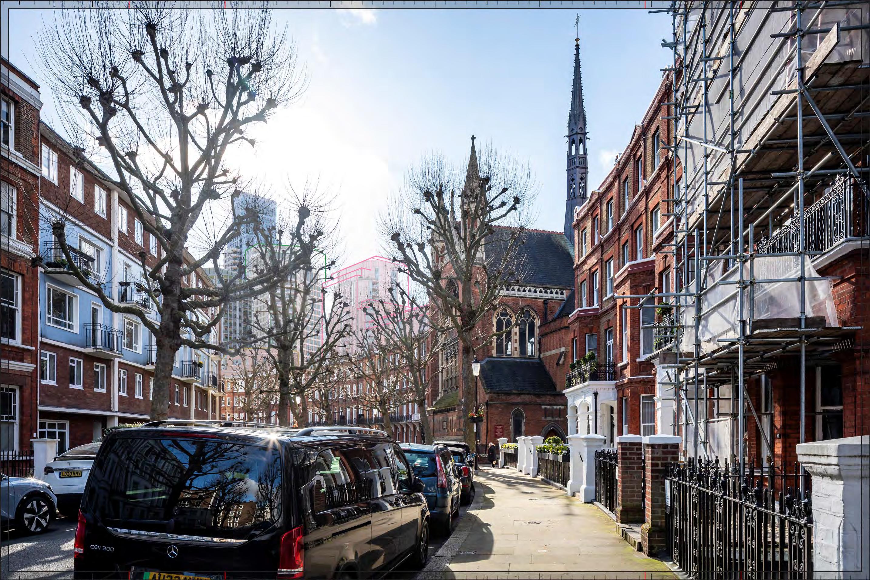
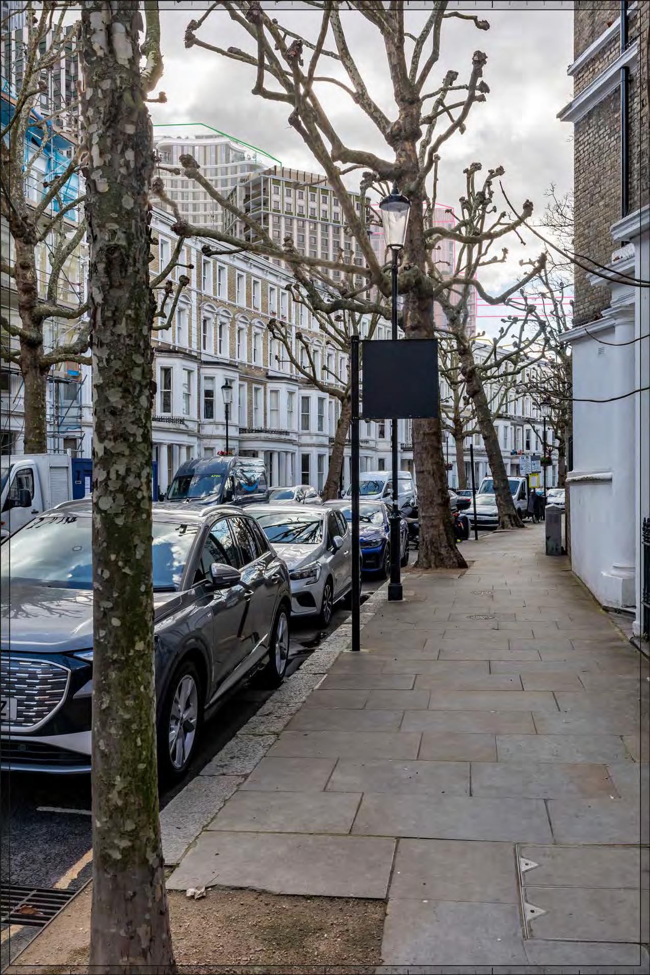
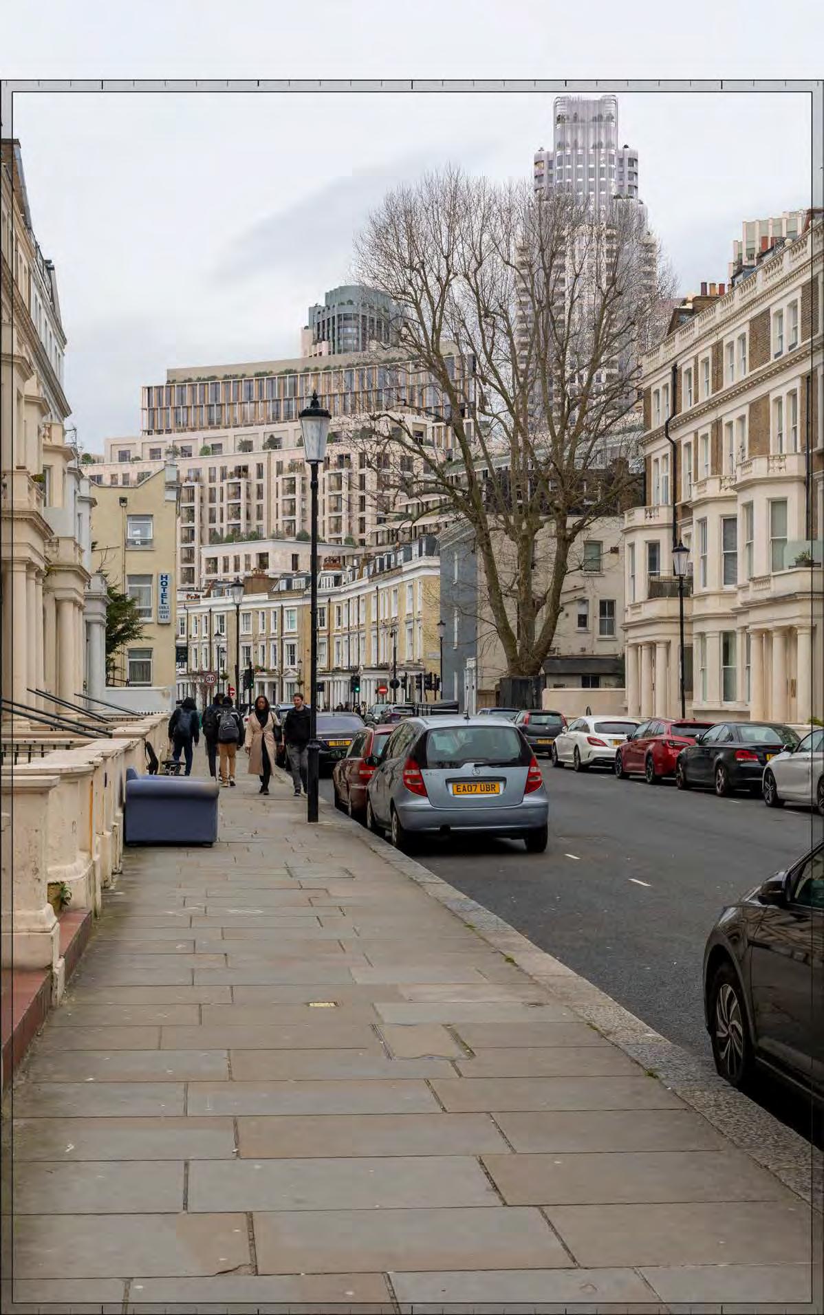
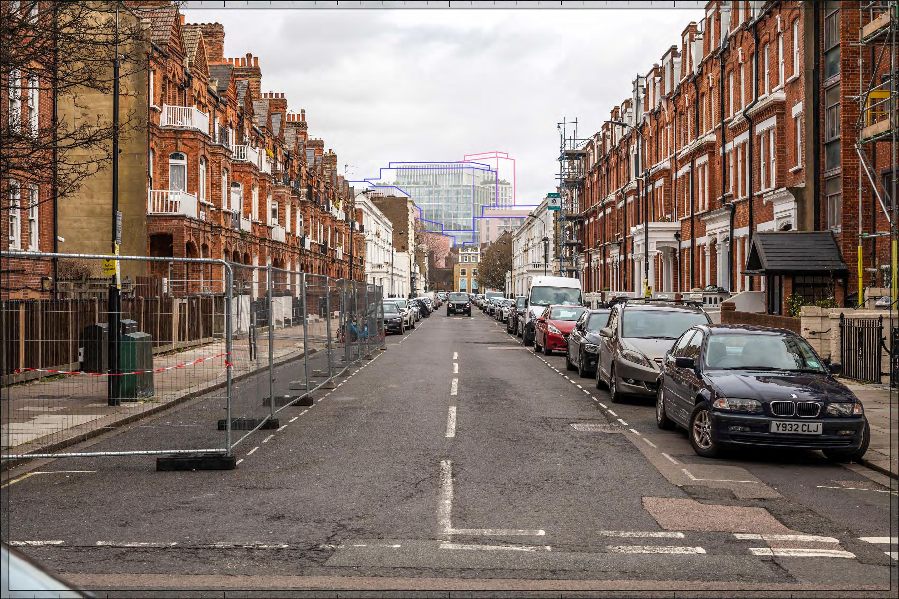
Proposed illustrative render of Outline Component within maximum parameter, All Phases
Mornington Avenue, west pavement, outside No.10
D28058 24mm 12/03/23 / 15:41
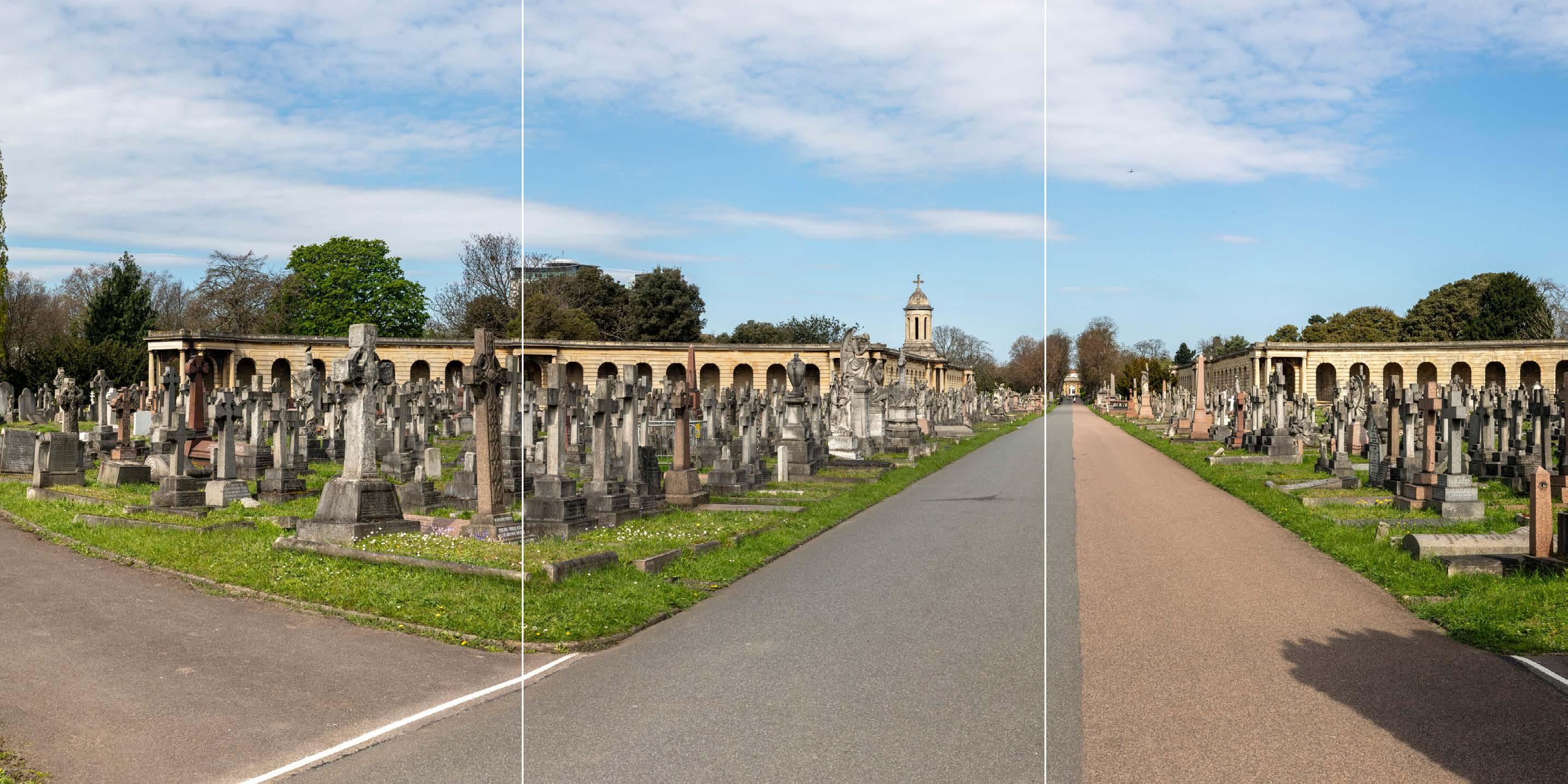
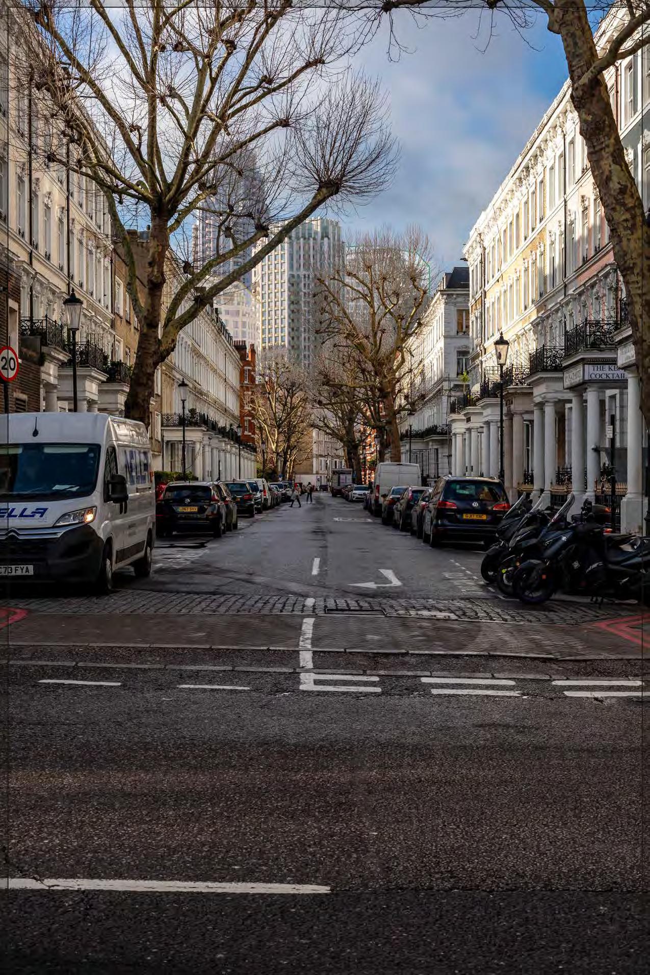
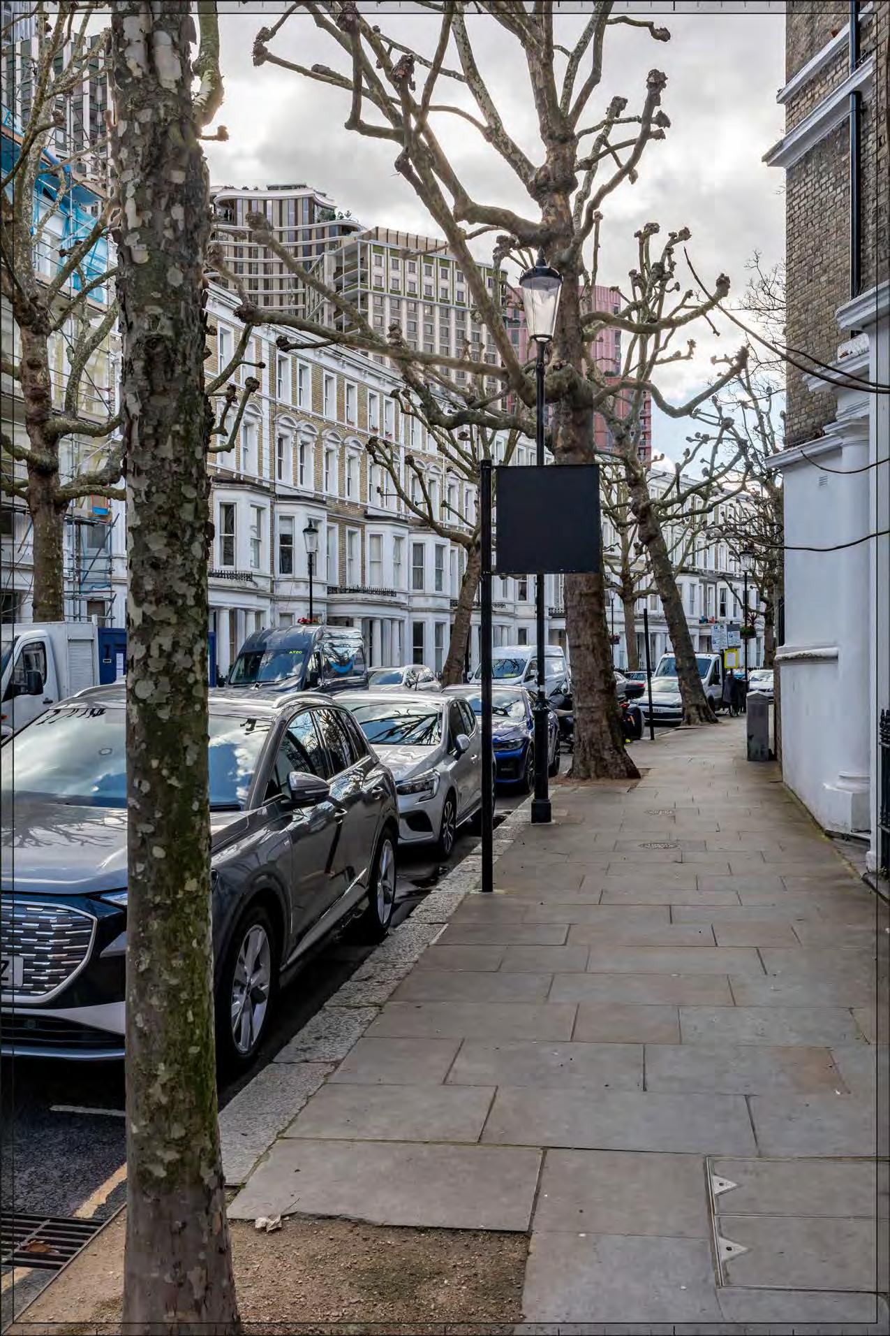
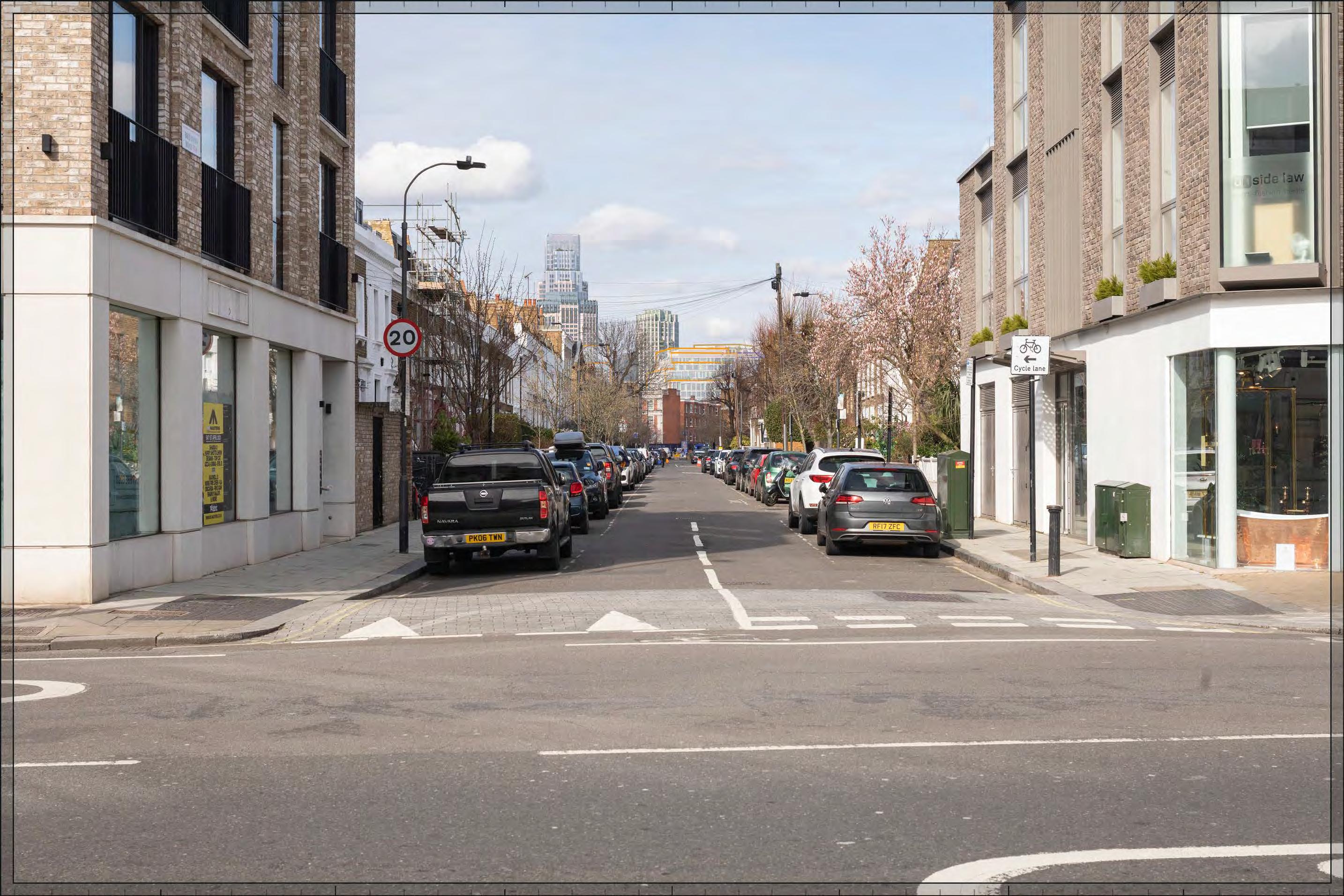
Proposed illustrative render of Outline Component, All Phases
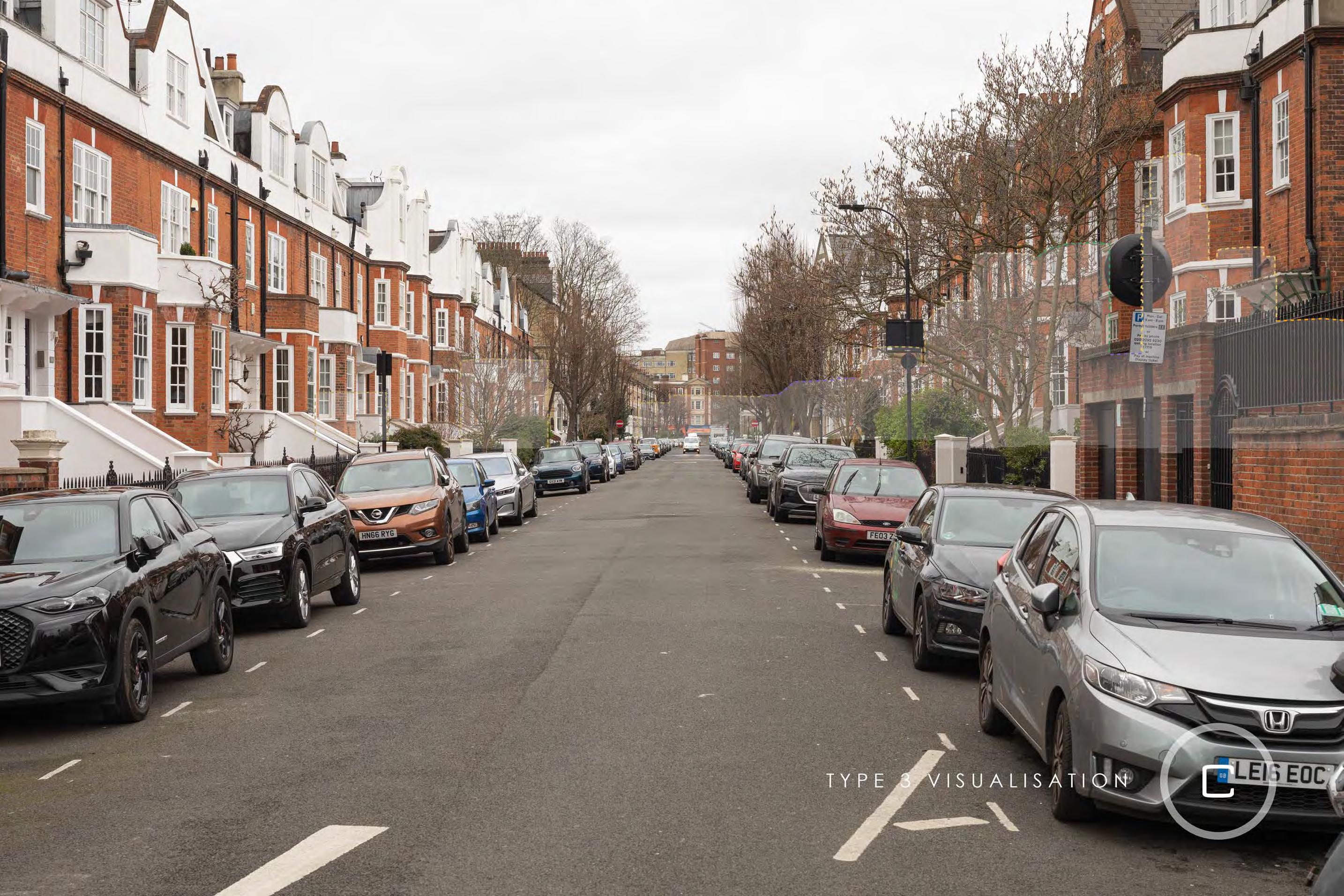
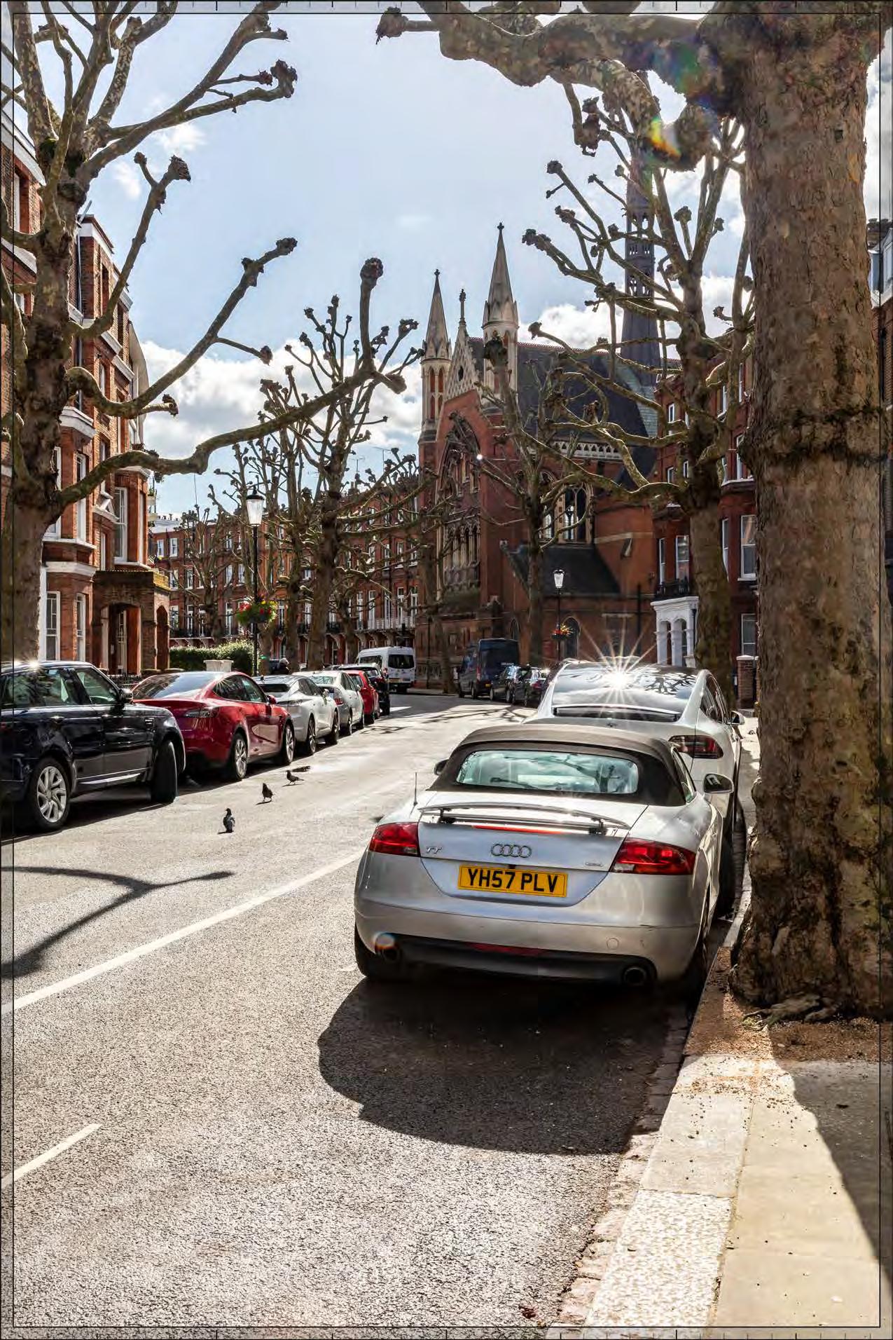
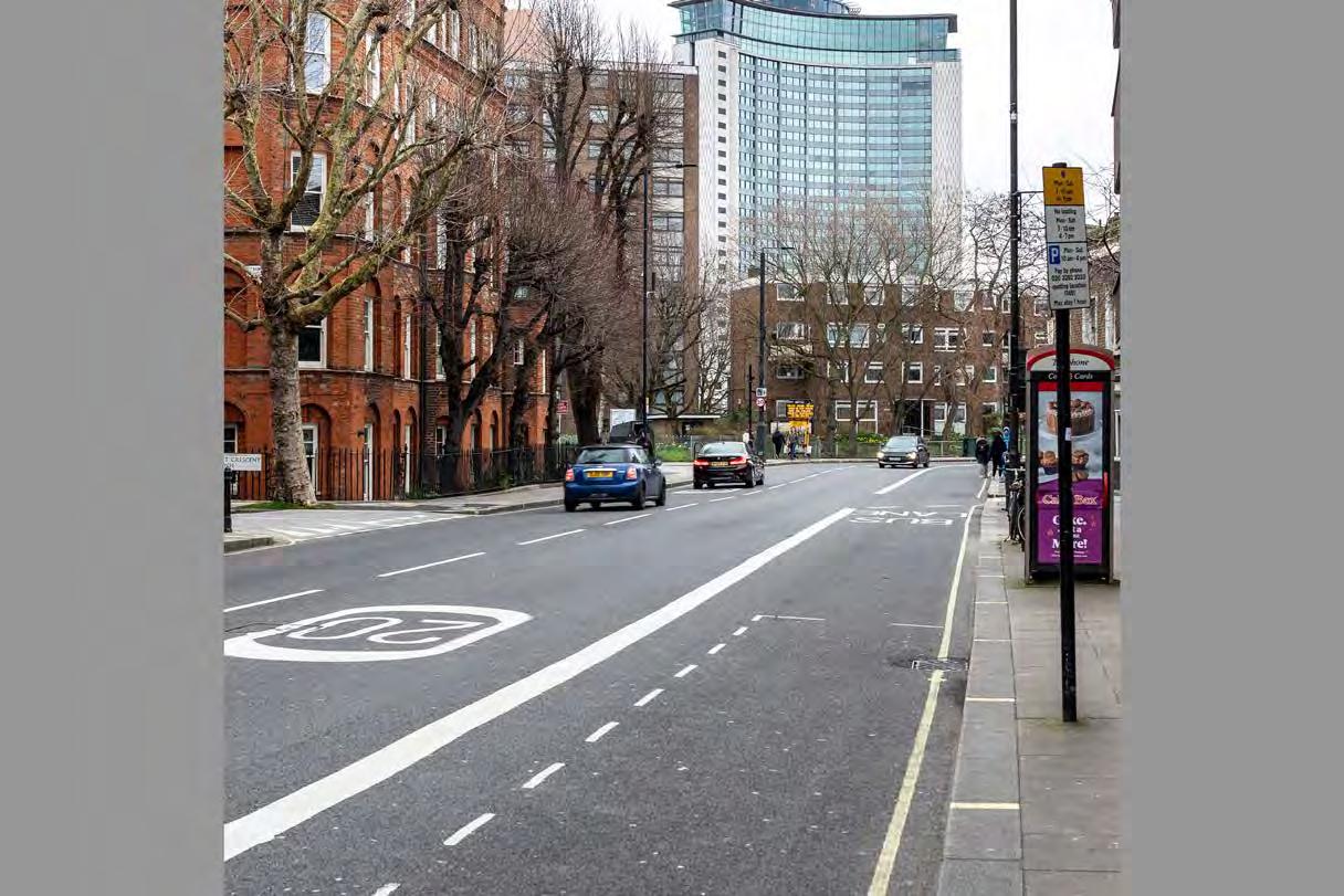
Talgarth Road
Talgarth Road
D28091x50 / 50mm 12/03/23 15:14
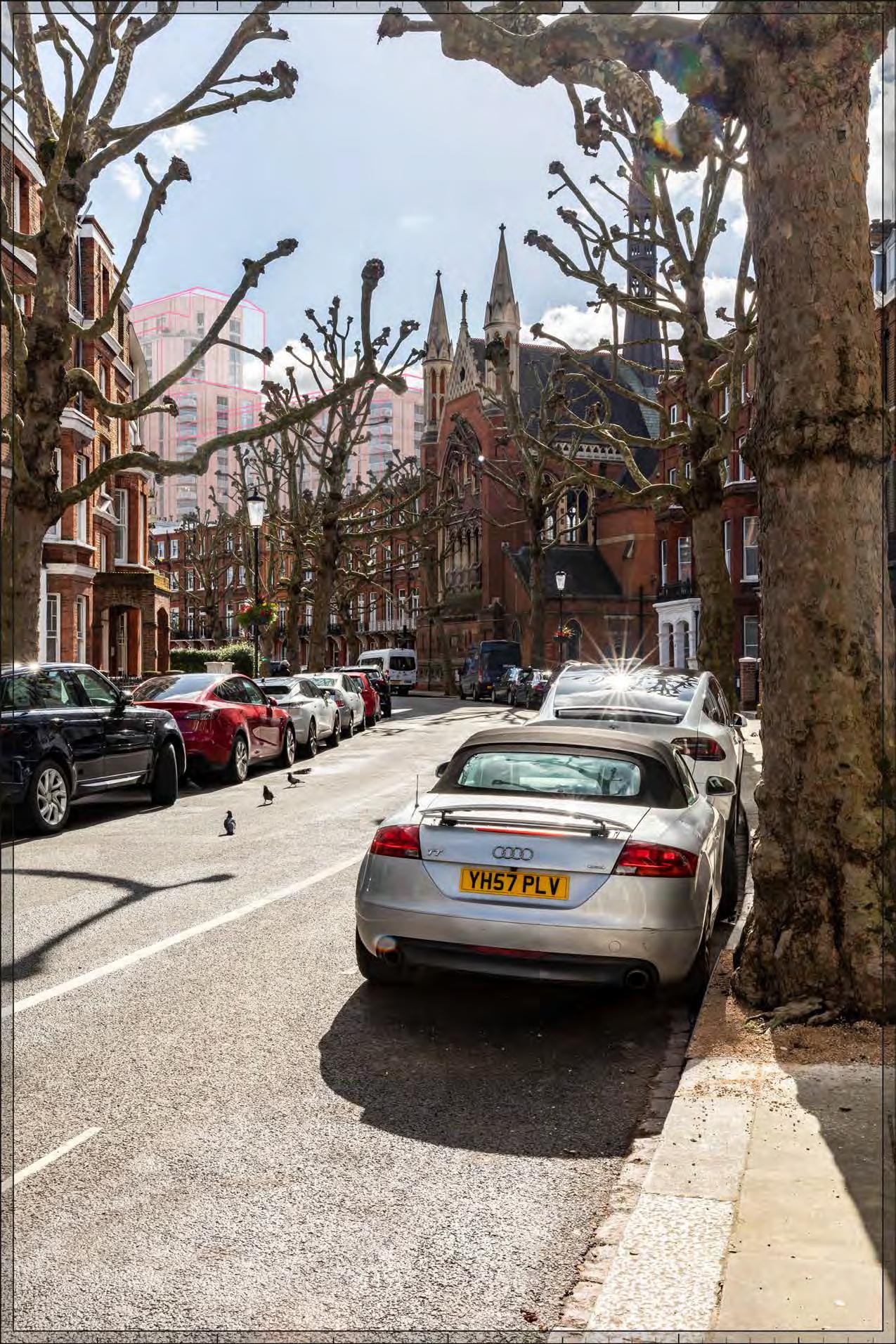
Proposed illustrative render of Outline Component within maximum parameter, Early Phases
Talgarth Road
D28091x50 / 50mm 12/03/23 15:14
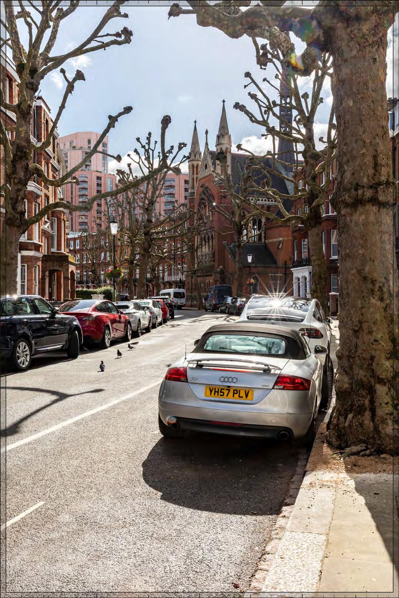
Proposed illustrative render of Outline Component, Early Phases
Talgarth Road
D28091x50 / 50mm 12/03/23 15:14
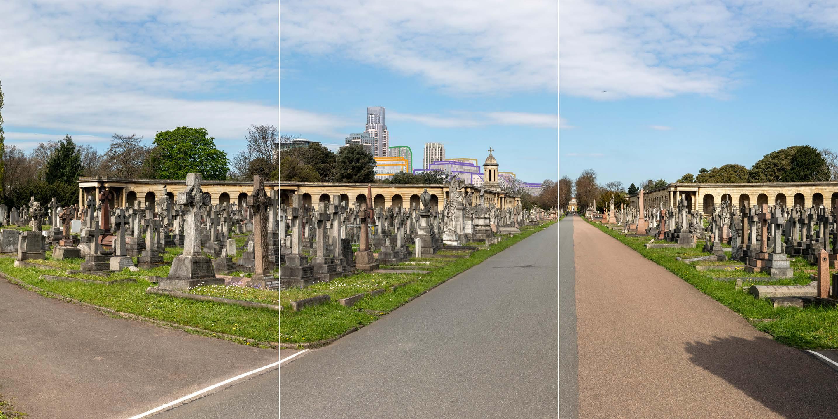
Proposed illustrative render of Outline Component within maximum parameter, All Phases
Talgarth Road
D28091x50 / 50mm 12/03/23 15:14
Proposed illustrative render of Outline Component, All Phases
Comeragh Road
Comeragh Road
D28057x50 / 50mm 12/03/23 13:45
Proposed illustrative render of Outline Component within maximum parameter, Early Phases
Comeragh Road
D28057x50 / 50mm 12/03/23 13:45
Proposed illustrative render of Outline Component, Early Phases
Comeragh Road
D28057x50 / 50mm 12/03/23 13:45
Proposed illustrative render of Outline Component within maximum parameter, All Phases
Comeragh Road
D28057x50 / 50mm 12/03/23 13:45
Proposed illustrative render of Outline Component, All Phases
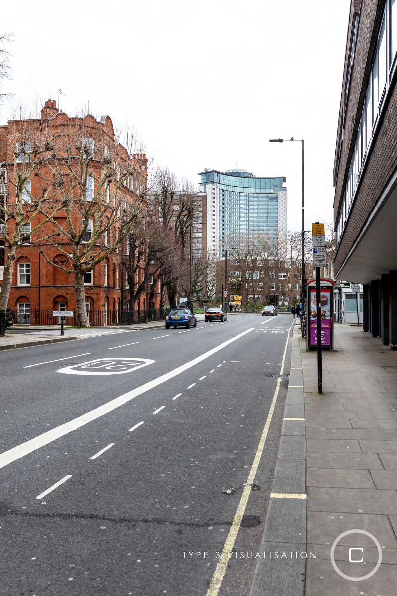
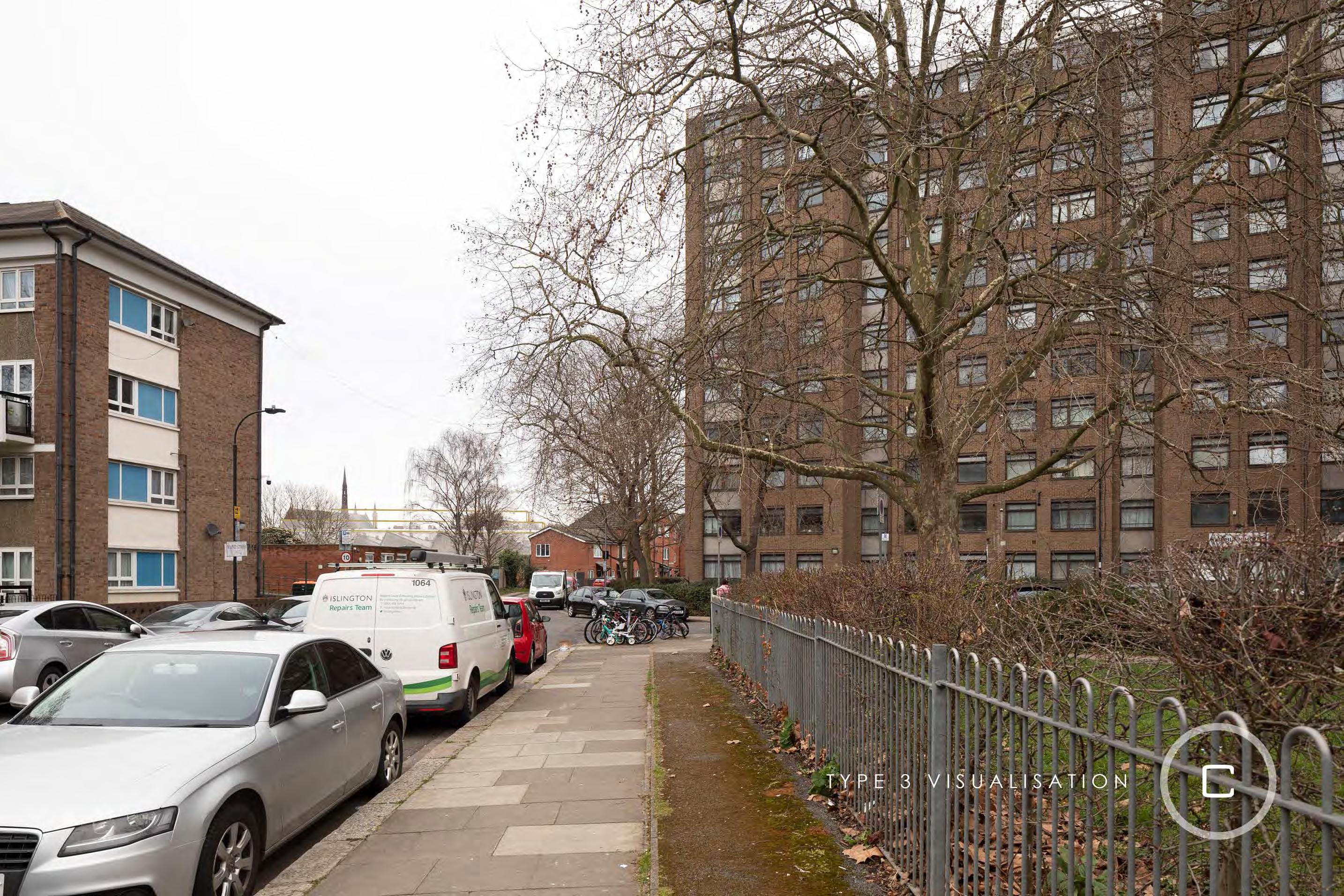
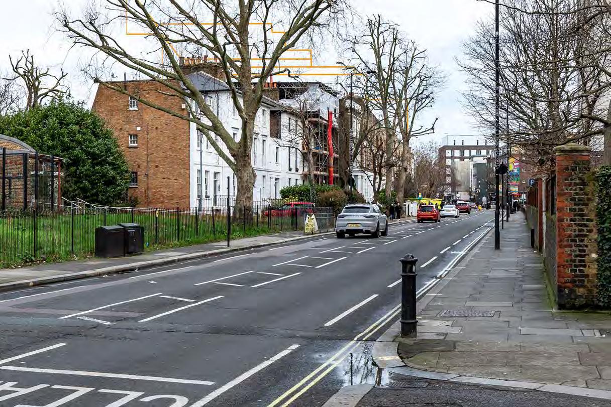
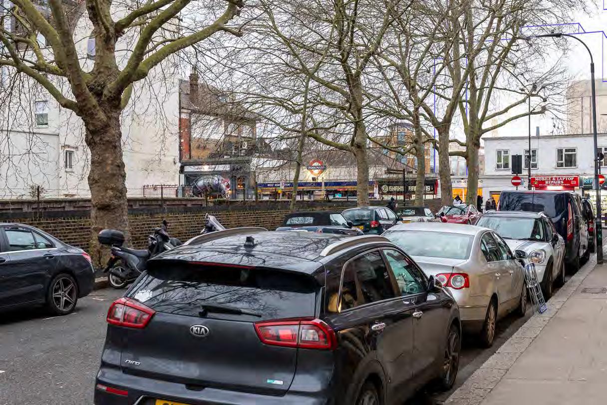
North End Road near junction with Mund Street
D28101 24mm 11/03/23 16:45
North End Road near junction with Mund Street
D28101 24mm 11/03/23 16:45
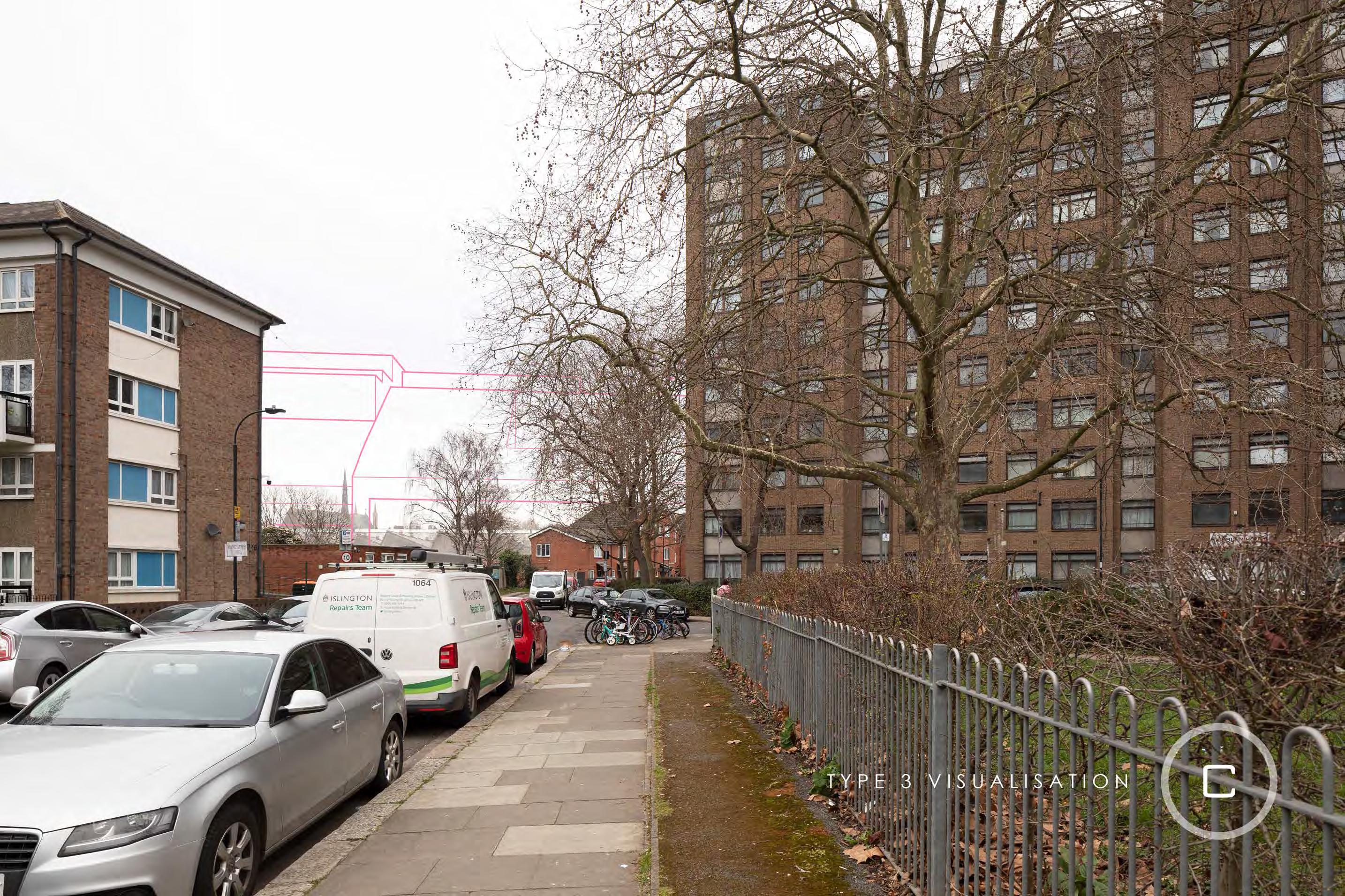
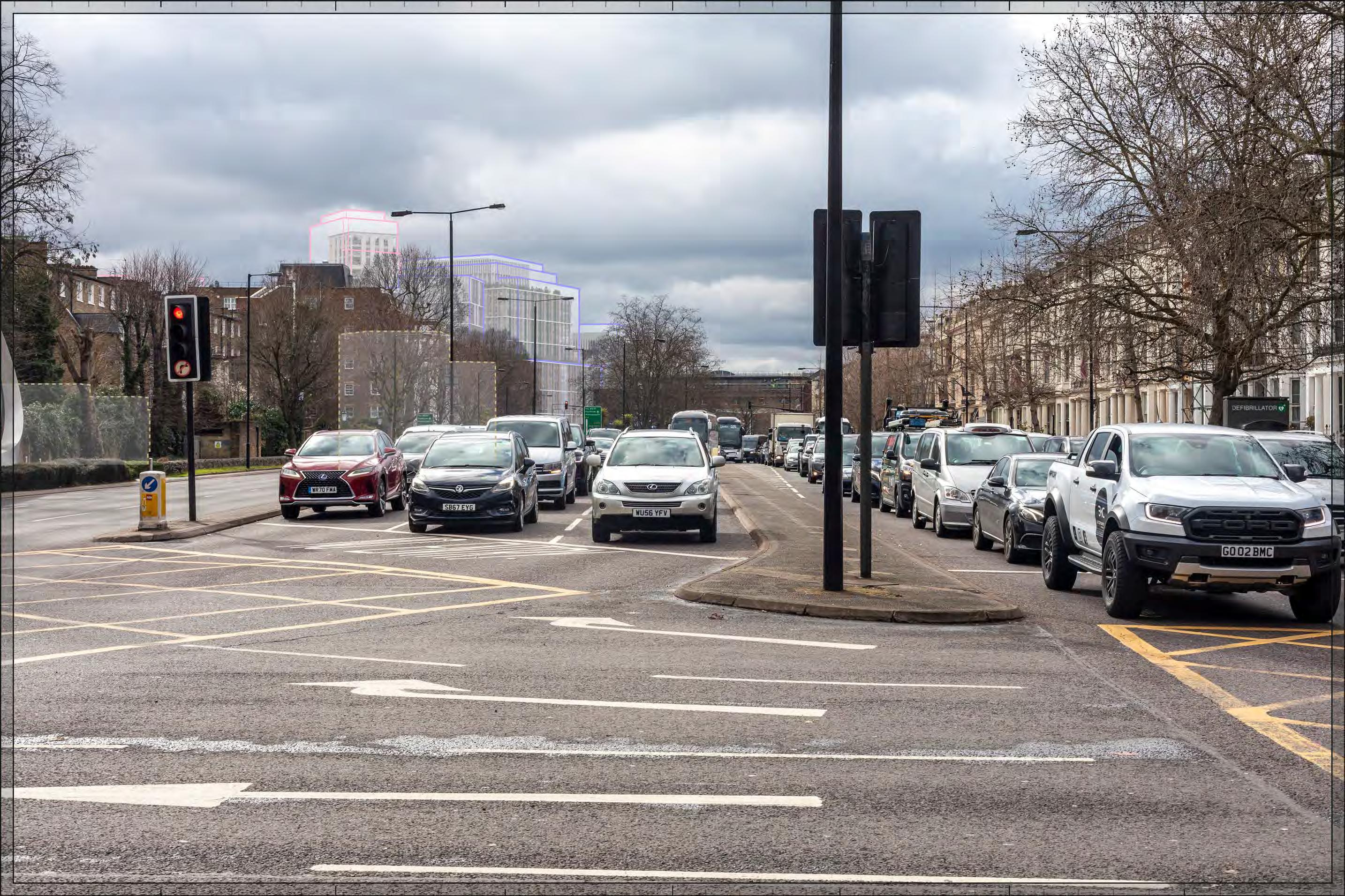
Proposed illustrative render of Outline Component within maximum parameter, Early Phases
North End Road near junction with Mund Street
D28101 24mm 11/03/23 16:45
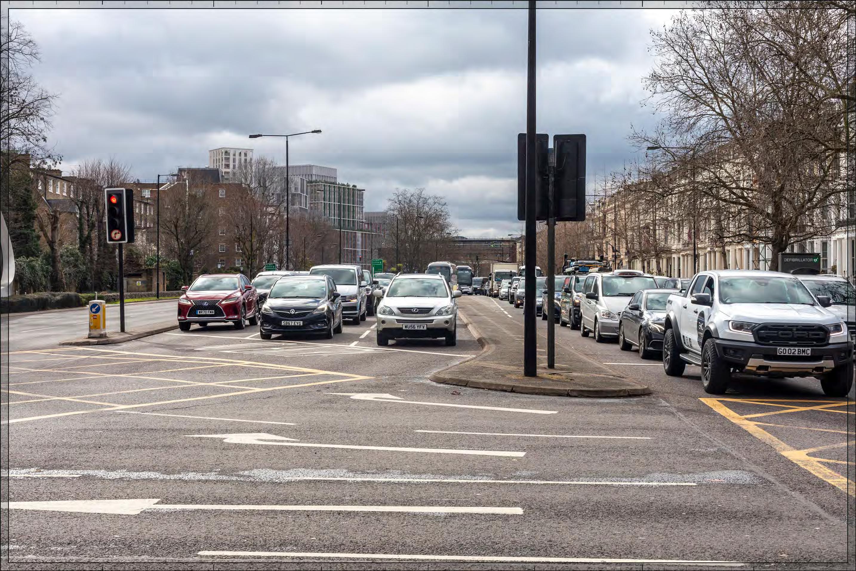
Proposed illustrative render of Outline Component, Early Phases
North End Road near junction with Mund Street
D28101 24mm 11/03/23 16:45
Proposed illustrative render of Outline Component within maximum parameter, All Phases
North End Road near junction with Mund Street
D28101 24mm 11/03/23 16:45
Proposed illustrative render of Outline Component, All Phases
Place D29850 24mm 04/03/24 / 14:27
Ivatt
Ivatt Place
D29850 24mm 04/03/24 / 14:27
Proposed illustrative render of Outline Component within maximum parameter, Early Phases
Ivatt Place
D29850 24mm 04/03/24 / 14:27
Proposed illustrative render of Outline Component, Early Phases
Ivatt Place
D29850 24mm 04/03/24 / 14:27
Proposed illustrative render of Outline Component within maximum parameter, All Phases
Ivatt Place
D29850 24mm 04/03/24 / 14:27
Proposed illustrative render of Outline Component, All Phases
Greyhound Road
D29849 24mm 04/03/24 / 14:55
Proposed illustrative render of Outline Component within maximum parameter, Early Phases
Greyhound Road
D29849 24mm 04/03/24 / 14:55
Proposed illustrative render of Outline Component, Early Phases
Greyhound Road
D29849 24mm 04/03/24 / 14:55
Proposed illustrative render of Outline Component within maximum parameter, All Phases
Greyhound Road
D29849 24mm 04/03/24 / 14:55
Proposed illustrative render of Outline Component, All Phases
Lillie Road, outside Beaufort Court
Lillie Road, outside Beaufort Court
D29786 24mm 15/02/24 / 12:31
Proposed illustrative render of Outline Component within maximum parameter, Early Phases
Lillie Road, outside Beaufort Court
D29786 24mm 15/02/24 / 12:31
Proposed illustrative render of Outline Component, Early Phases
Lillie Road, outside Beaufort Court
D29786 24mm 15/02/24 / 12:31
Proposed illustrative render of Outline Component within maximum parameter, All Phases
Lillie Road, outside Beaufort Court
D29786 24mm 15/02/24 / 12:31
Proposed illustrative render of Outline Component, All Phases
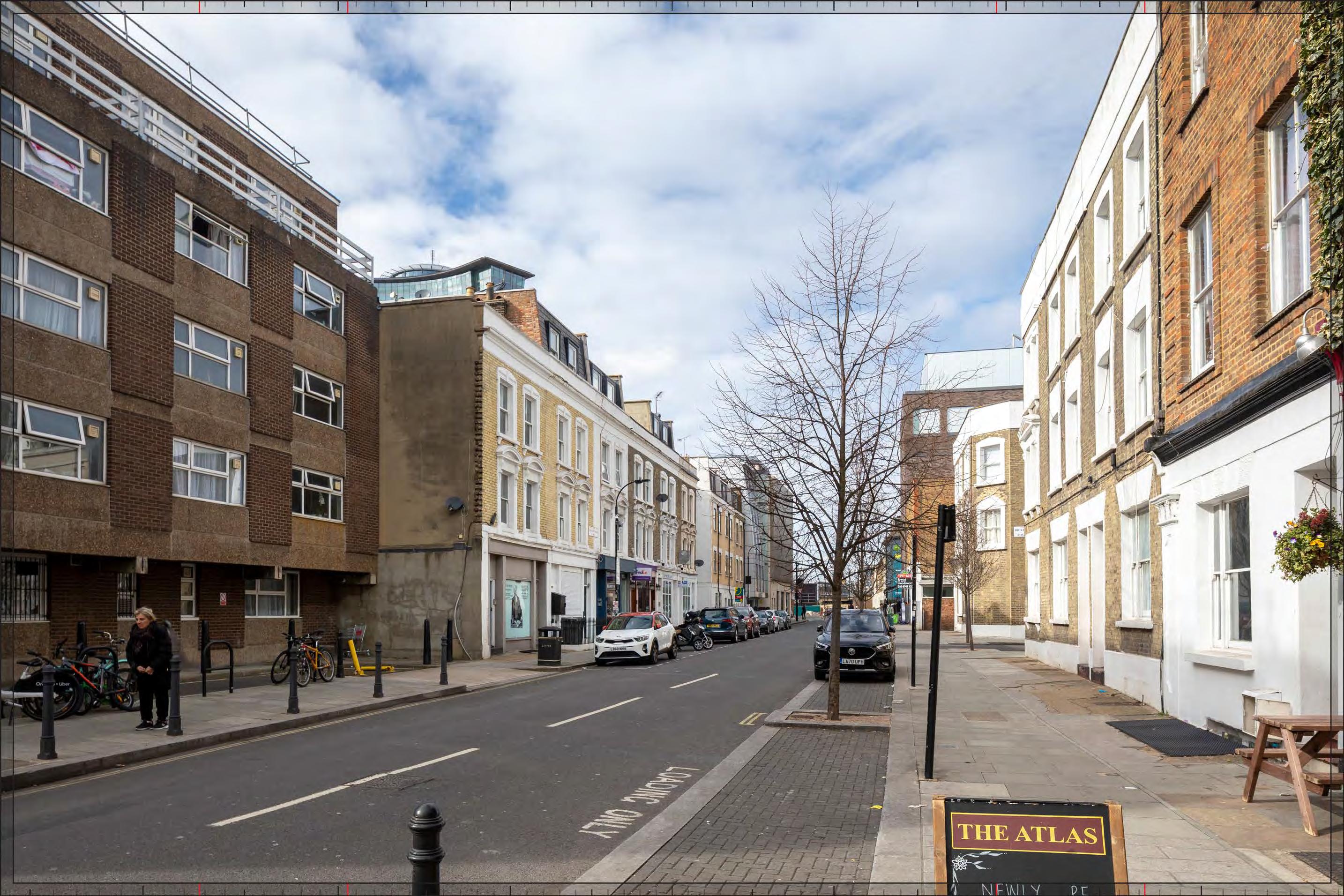
Ongar Road
D28071 24mm 11/03/23 14:25
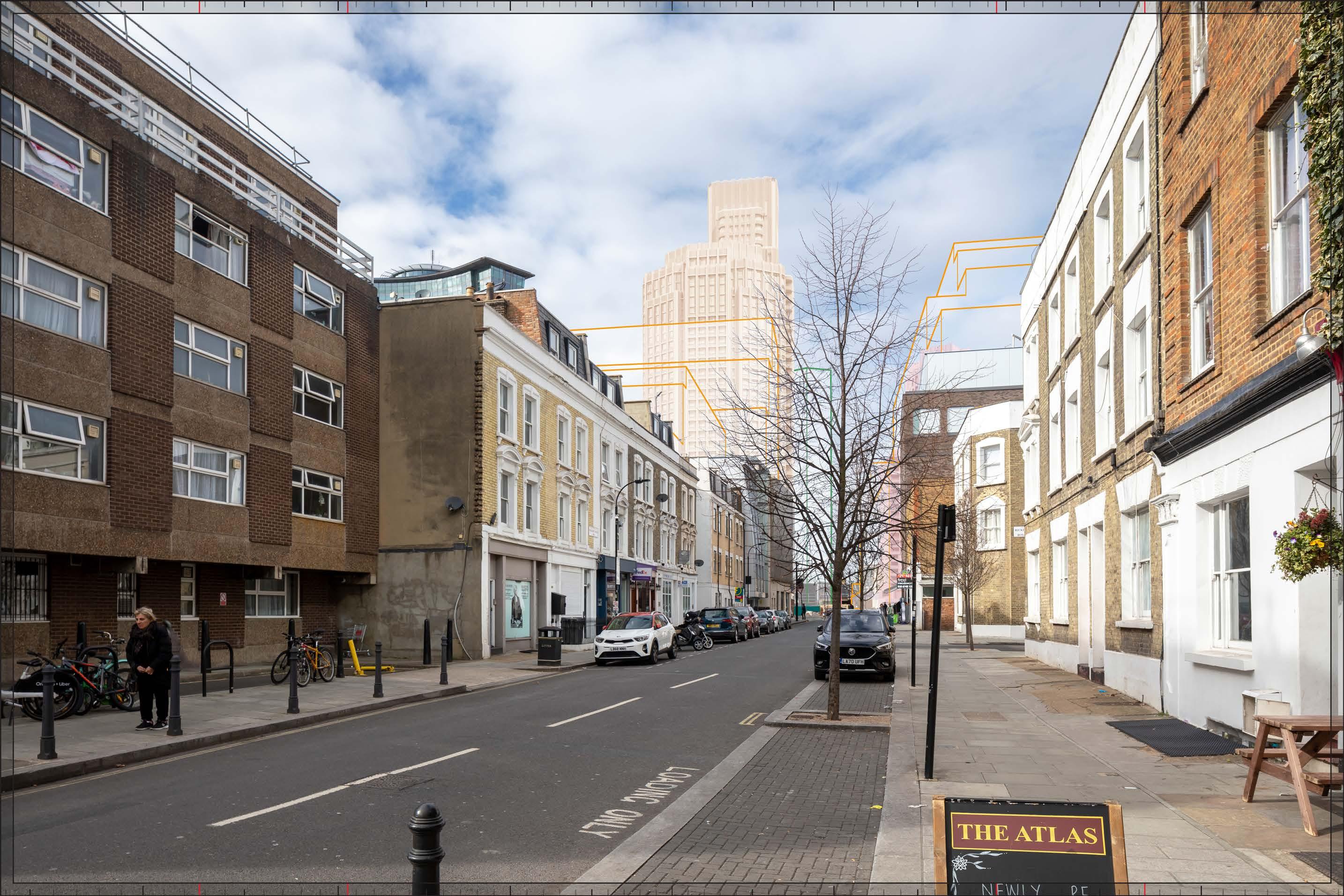
Proposed illustrative render of Outline Component within maximum parameter, Early Phases
Ongar Road D28071 24mm 11/03/23 14:25
Proposed illustrative render of Outline Component, Early Phases
Ongar Road
D28071 24mm 11/03/23 14:25
Proposed illustrative render of Outline Component within maximum parameter, All Phases
Ongar Road
D28071 24mm 11/03/23 14:25
Proposed illustrative render of Outline Component, All Phases
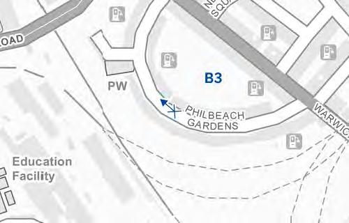
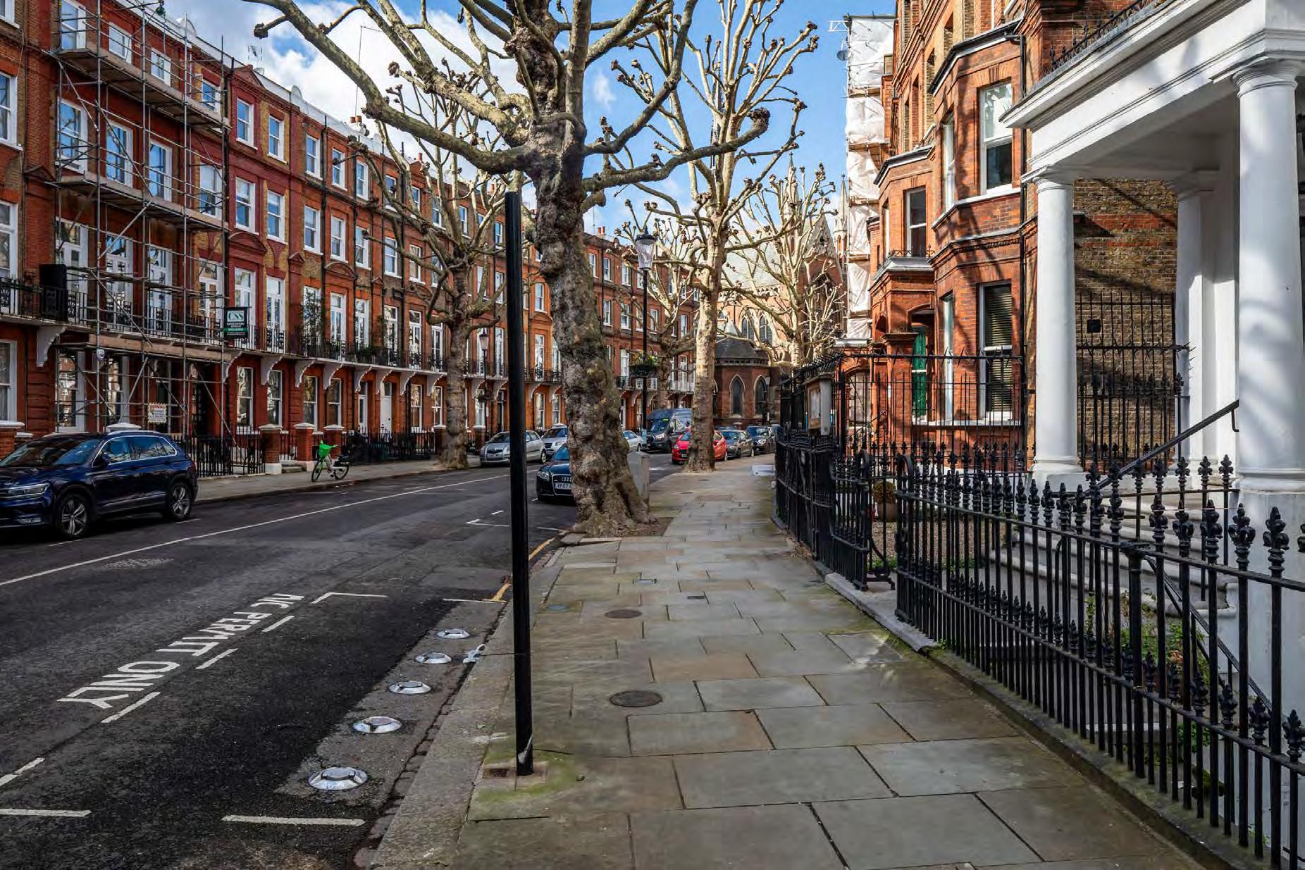
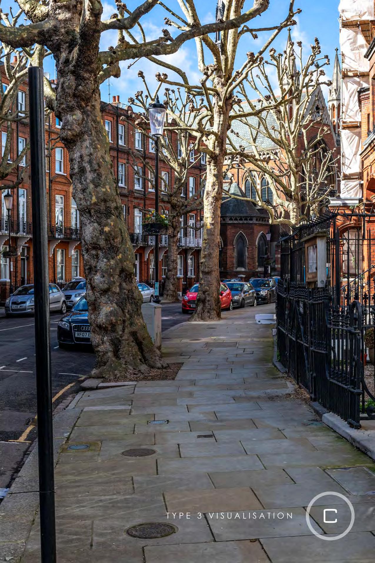
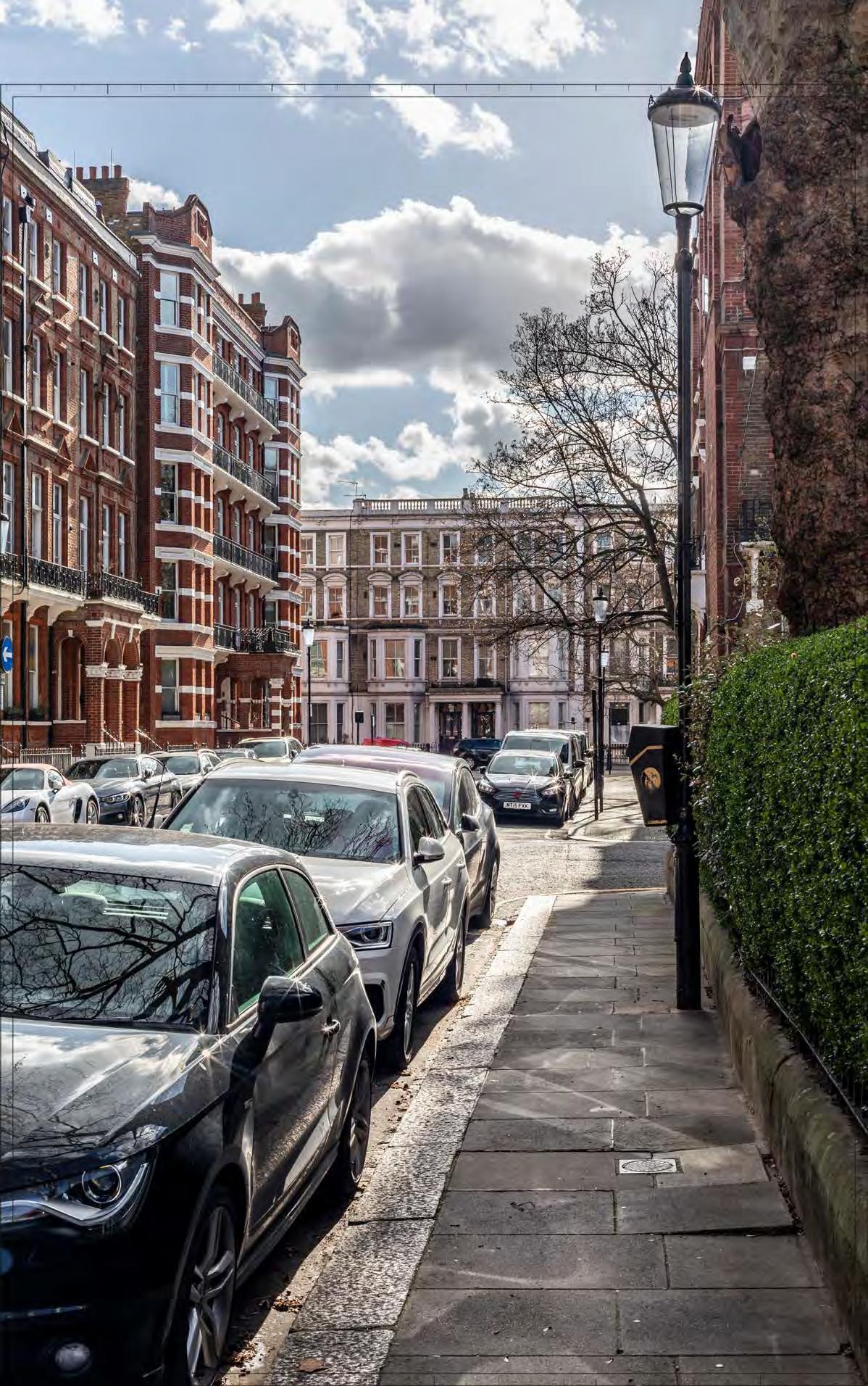
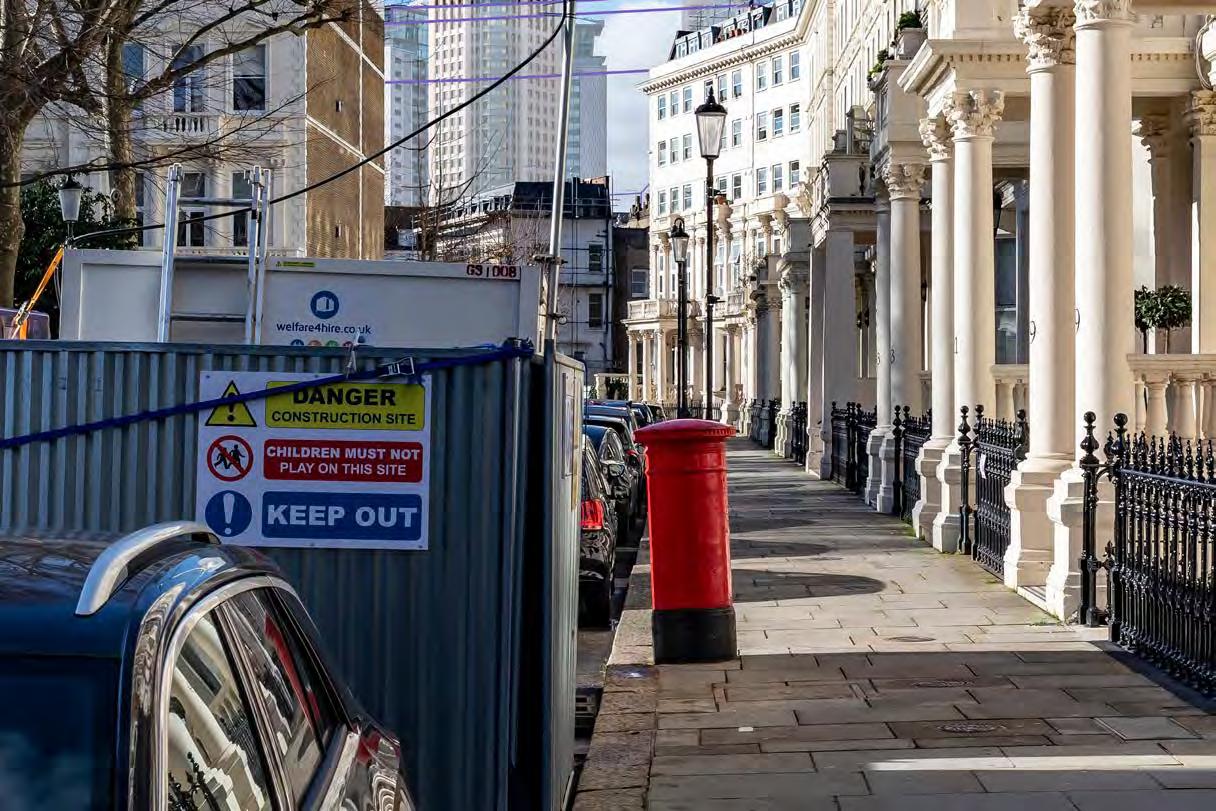
Philbeach Gardens, north pavement at junction with Warwick Road (north end)
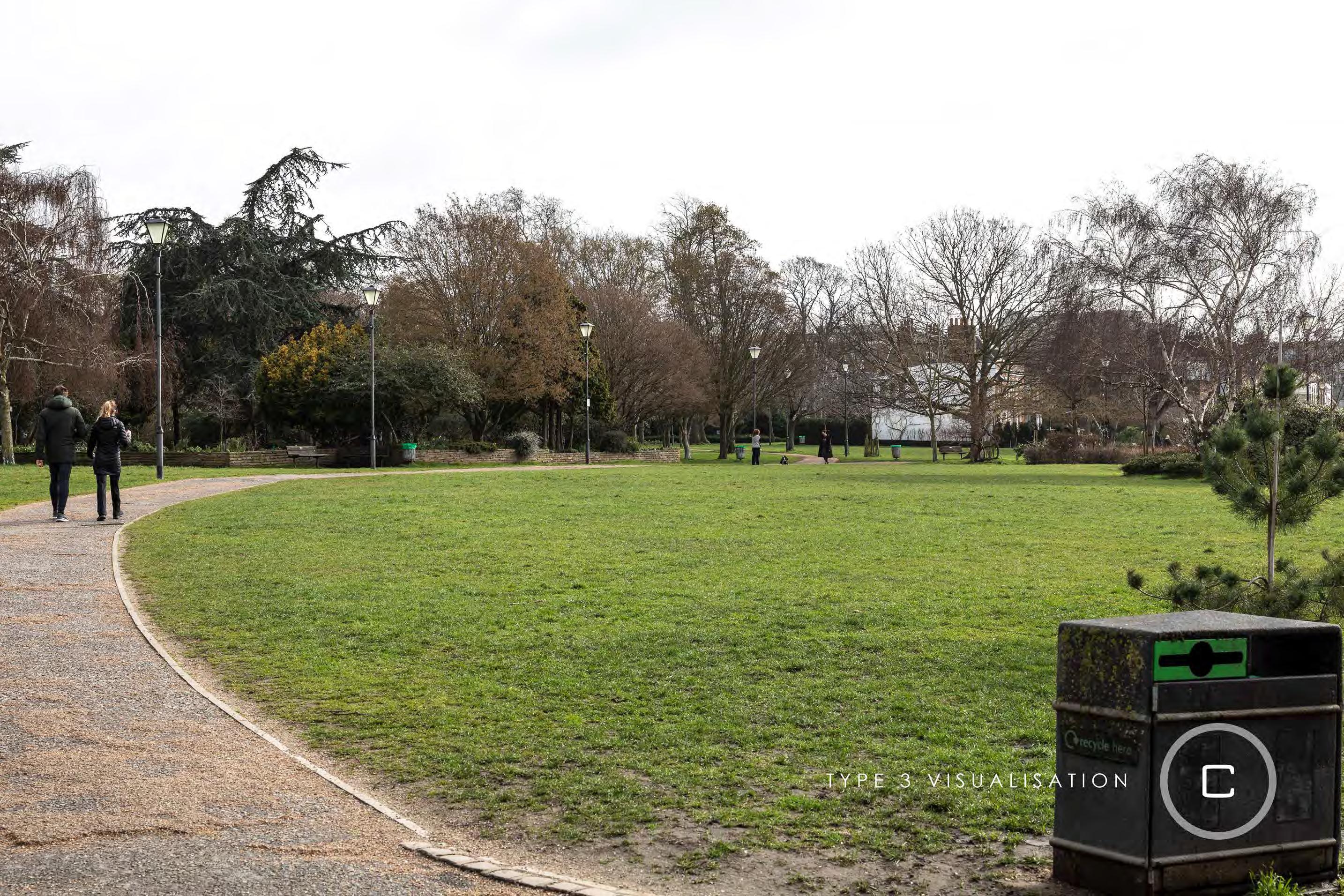
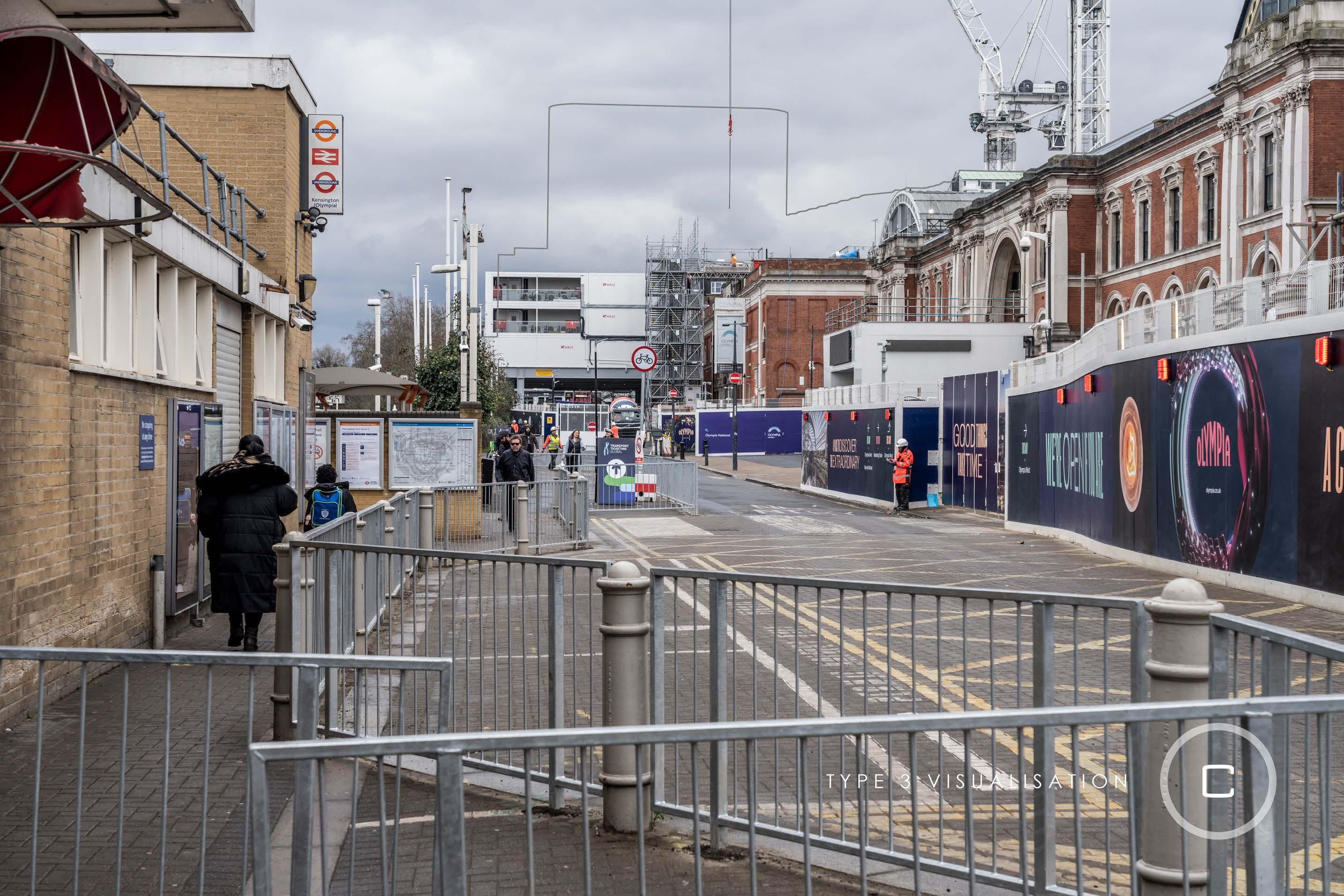
Existing
Philbeach Gardens, north pavement at junction with Warwick Road (north end)
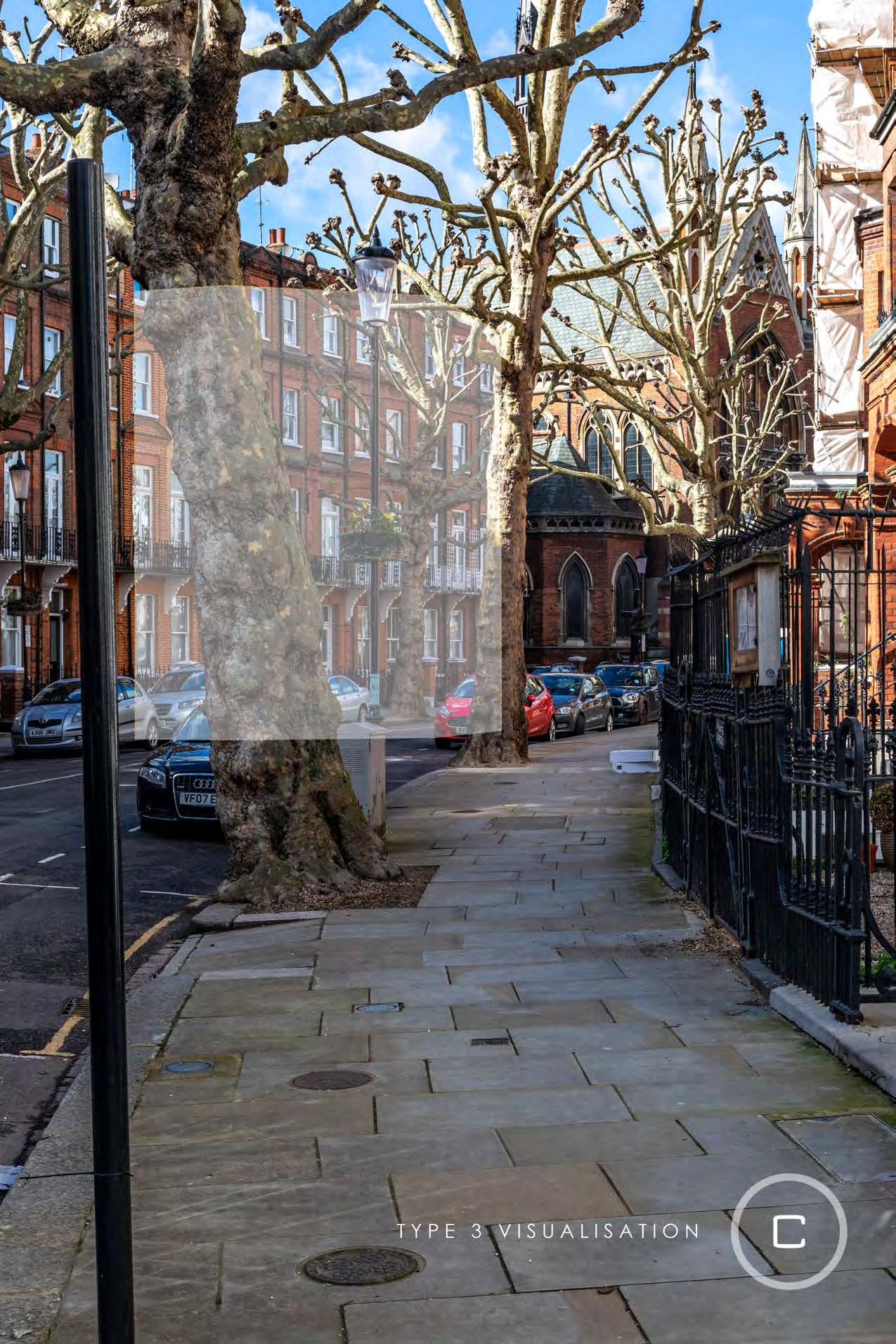
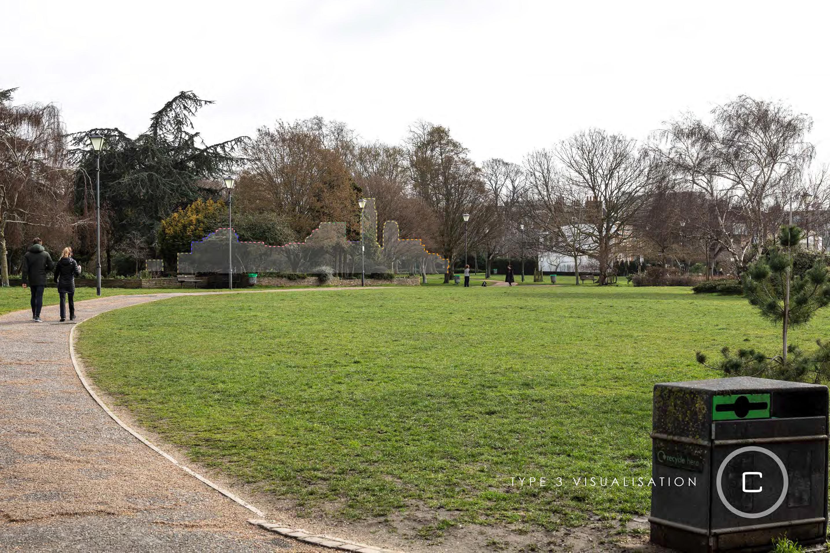
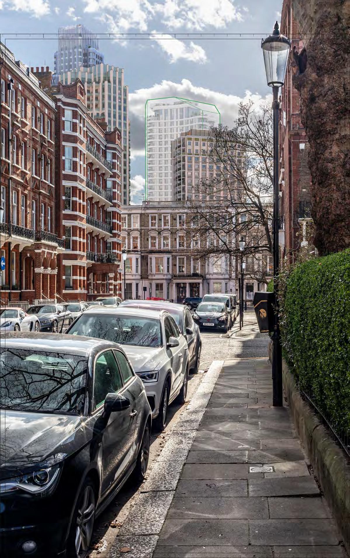
Proposed illustrative render of Outline Component within maximum parameter, Early Phases
Philbeach Gardens, north pavement at junction with Warwick Road (north end)
Proposed illustrative render of Outline Component, Early Phases
Philbeach Gardens, north pavement at junction with Warwick Road (north end)
Proposed illustrative render of Outline Component within maximum parameter, All Phases
Philbeach Gardens, north pavement at junction with Warwick Road (north end)
Proposed illustrative render of Outline Component, All Phases
Earls Court Square, north side
Court Square, north side D29715x35 / 35mm 16/02/24 11:01
Proposed illustrative render of Outline Component within maximum parameter, Early Phases
Earls
Earls Court Square, north side
Proposed illustrative render of Outline Component, Early Phases
Court Square, north side D29715x35 / 35mm 16/02/24 11:01
Proposed illustrative render of Outline Component within maximum parameter, All Phases
Earls
Earls Court Square, north side
Proposed illustrative render of Outline Component, All Phases
Southeast corner of Finborough Road and Old Brompton Road
D29717x35 / 35mm 16/02/24 10:41
Southeast corner of Finborough Road and Old Brompton Road
D29717x35 / 35mm 16/02/24 10:41
Proposed illustrative render of Outline Component within maximum parameter, Early Phases
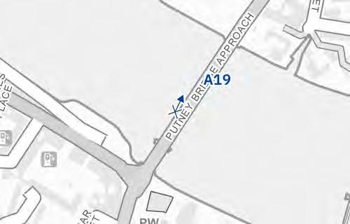
View A18
Southeast corner of Finborough Road and Old Brompton Road
D29717x35 / 35mm 16/02/24 10:41
Proposed illustrative render of Outline Component, Early Phases
Southeast corner of Finborough Road and Old Brompton Road
D29717x35 / 35mm 16/02/24 10:41
Proposed illustrative render of Outline Component within maximum parameter, All Phases
View A18
Southeast corner of Finborough Road and Old Brompton Road D29717x35 / 35mm 16/02/24 10:41
Proposed illustrative render of Outline Component, All Phases
Charleville Road –from outside 26 Gledstanes Road
D28152x50 / 50mm 12/03/23 13:56
Existing
Charleville Road –from outside 26 Gledstanes Road
D28152x50 / 50mm 12/03/23 13:56
Proposed illustrative render of Outline Component within maximum parameter, Early Phases
Charleville Road –from outside 26 Gledstanes Road
D28152x50 / 50mm 12/03/23 13:56
Proposed illustrative render of Outline Component, Early Phases
Charleville Road –from outside 26 Gledstanes Road
D28152x50 / 50mm 12/03/23 13:56
Proposed illustrative render of Outline Component within maximum parameter, All Phases
Charleville Road –from outside 26 Gledstanes Road
D28152x50 / 50mm 12/03/23 13:56
Proposed illustrative render of Outline Component, All Phases
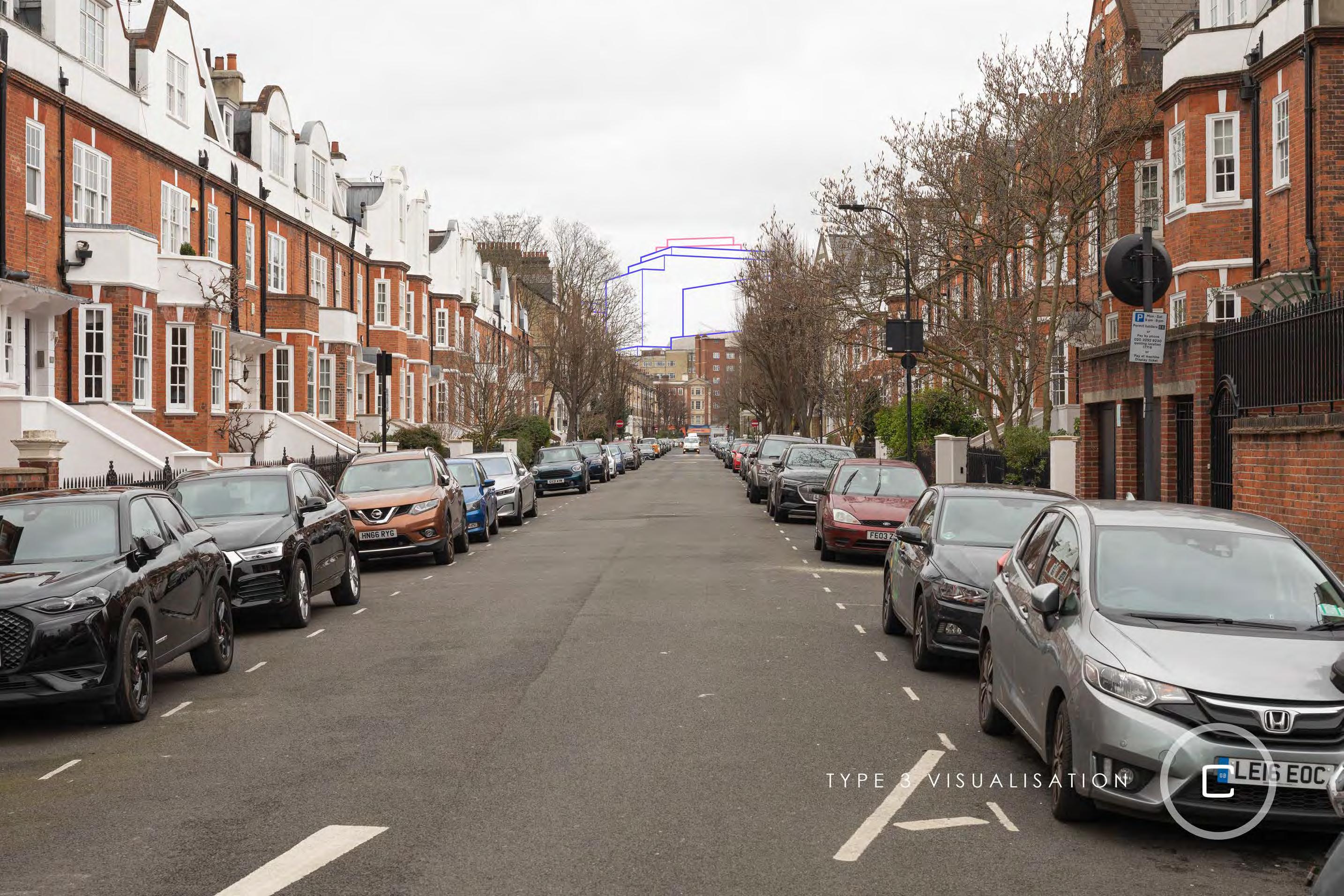
Talgarth Road
D29794x50 / 50mm 15/02/24 14:25
Proposed illustrative render of Outline Component within maximum parameter, Early Phases
Talgarth Road D29794x50 / 50mm 15/02/24 14:25
Proposed illustrative render of Outline Component, Early Phases
Talgarth Road
D29794x50 / 50mm 15/02/24 14:25
Proposed illustrative render of Outline Component within maximum parameter, All Phases
Talgarth
Road D29794x50 / 50mm 15/02/24 14:25
Proposed illustrative render of Outline Component, All Phases
View22View22
Nevern Square sequence, eastern edge
24N
23
Nevern Square, south side
Gardens, Outside No.65 View 25
24
Court Road, looking along Trebivor Road
Philbeach Gardens, outside No.61 View 26
Earls Court Road, looking along Trebivor Road (Dusk)
View
Philbeach
Earls
27
Philbeach Gardens, north pavement at junction with Warwick Road (south end)
View 41
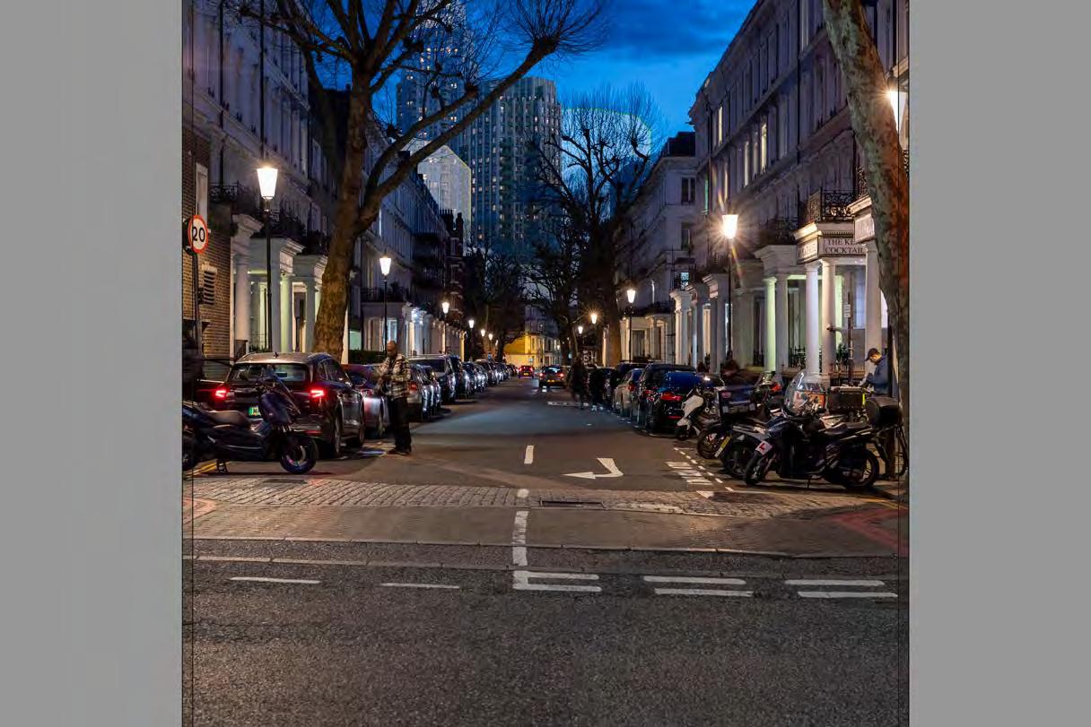
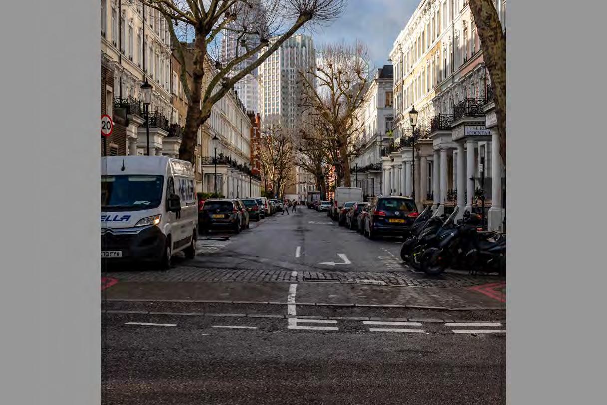
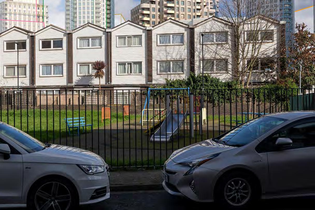
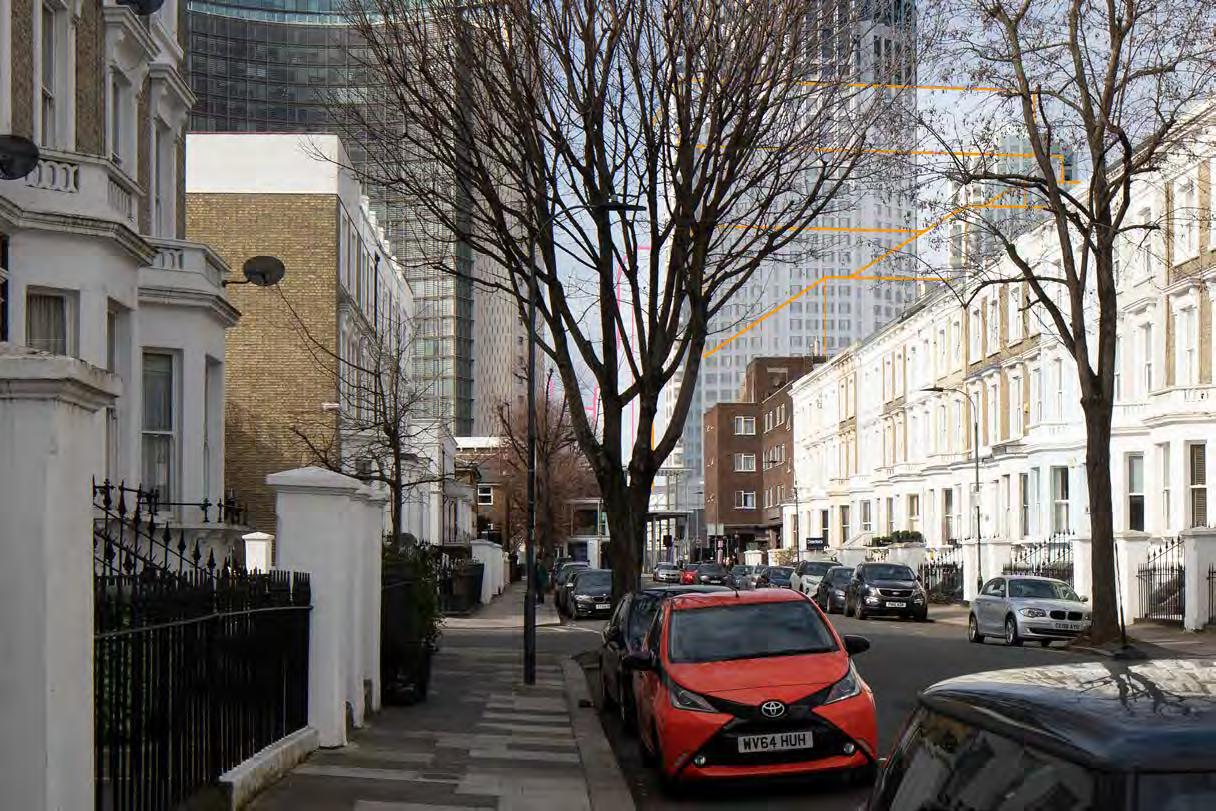
Mornington Avenue, west pavement, outside No.10
Nevern Square, south side View 28
View 48
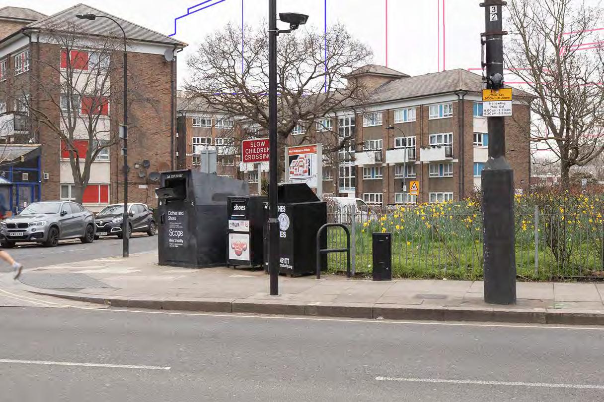
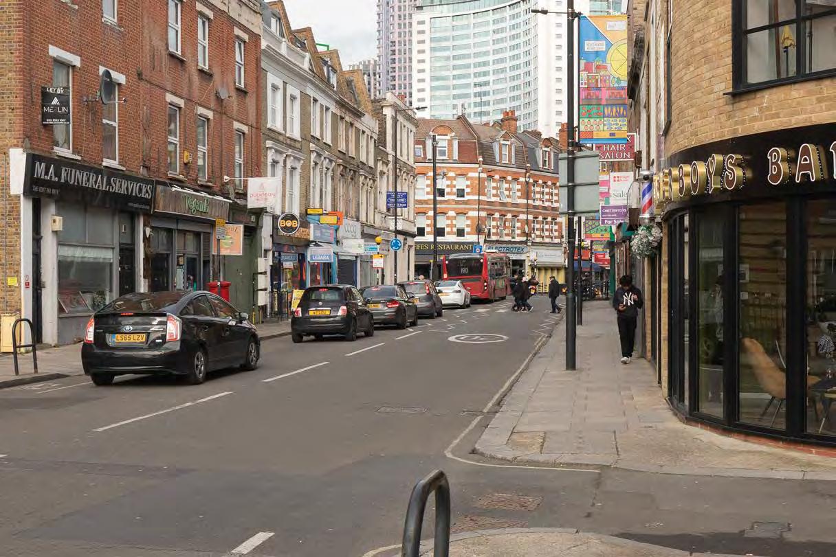
North End Road near junction with Mund Street
Earls Court Square, south side
View 49 View 30
Ivatt Place
50
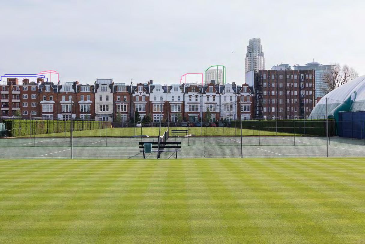
The Queens Club
View 53
Archel Road
View 51N View 51
Greyhound Road
Normand Park View 54
Greyhound Road (Dusk)
Lille Road, west of North End Road junction View 55
View 59 View 56
View A12
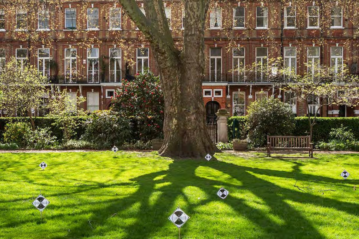
Nevern Square sequence, centre of the garden
View 57
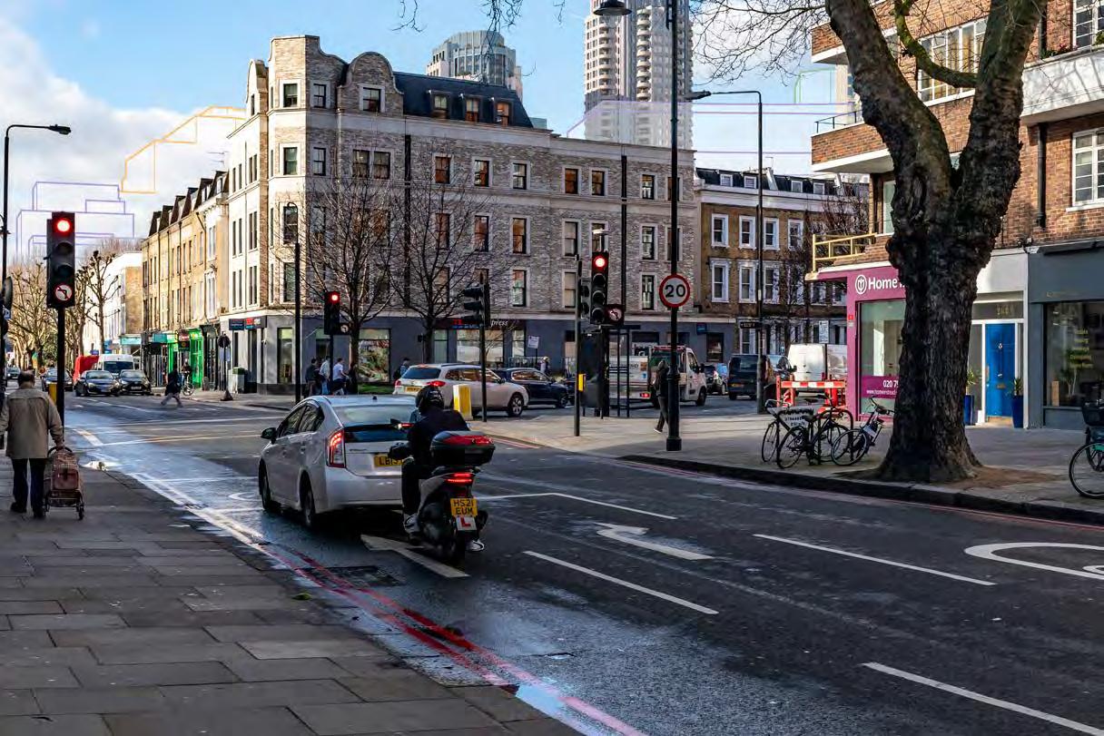
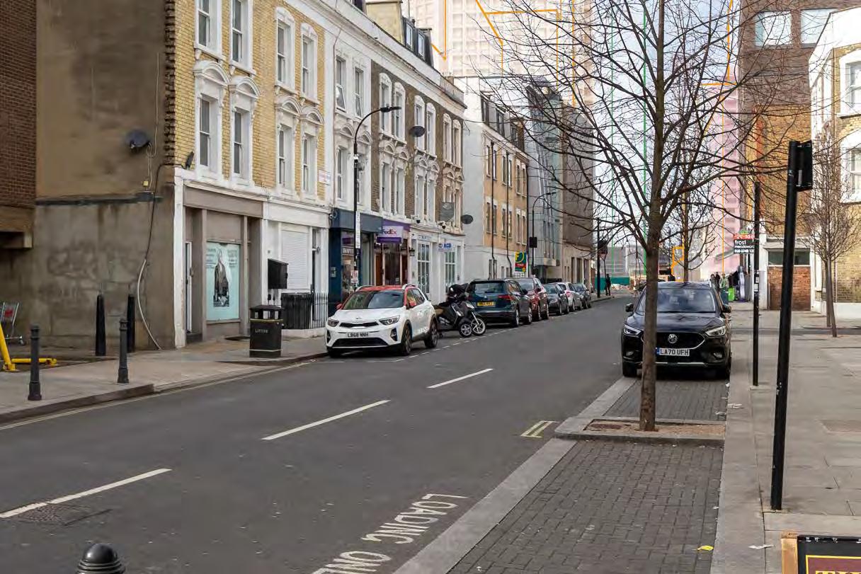
North End Road at the junction with Dawes Road
View A13
Philbeach Gardens, north pavement at junction with Warwick Road (north end)
Ongar Road
View A14
Philbeach Gardens south pavement at junction with Warwick Road (south end)
Lillie Road, outside Beaufort Court
View A15
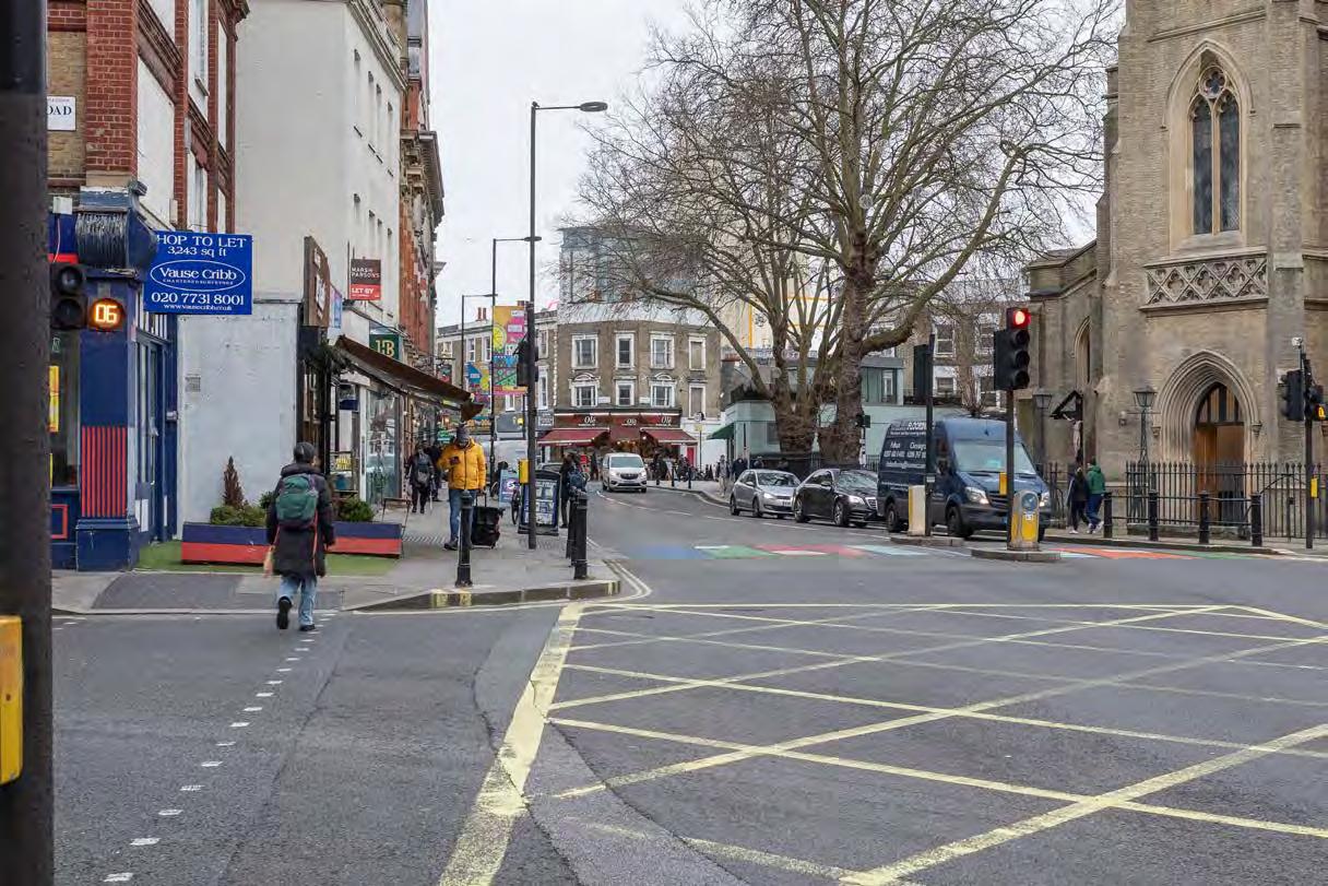
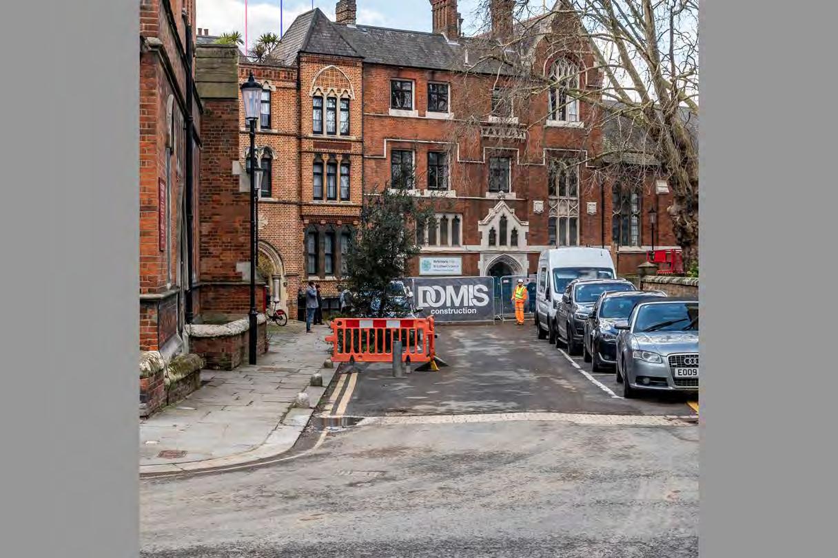
Philbeach Gardens - opposite St Cuthberts Church
View A18
Southeast corner of Finborough Road and Old Brompton Road
Eardley Crescent, south end, at junction with Old Brompton Road
View A33 View A17 View A16
Earls Court Square, north side
View A29
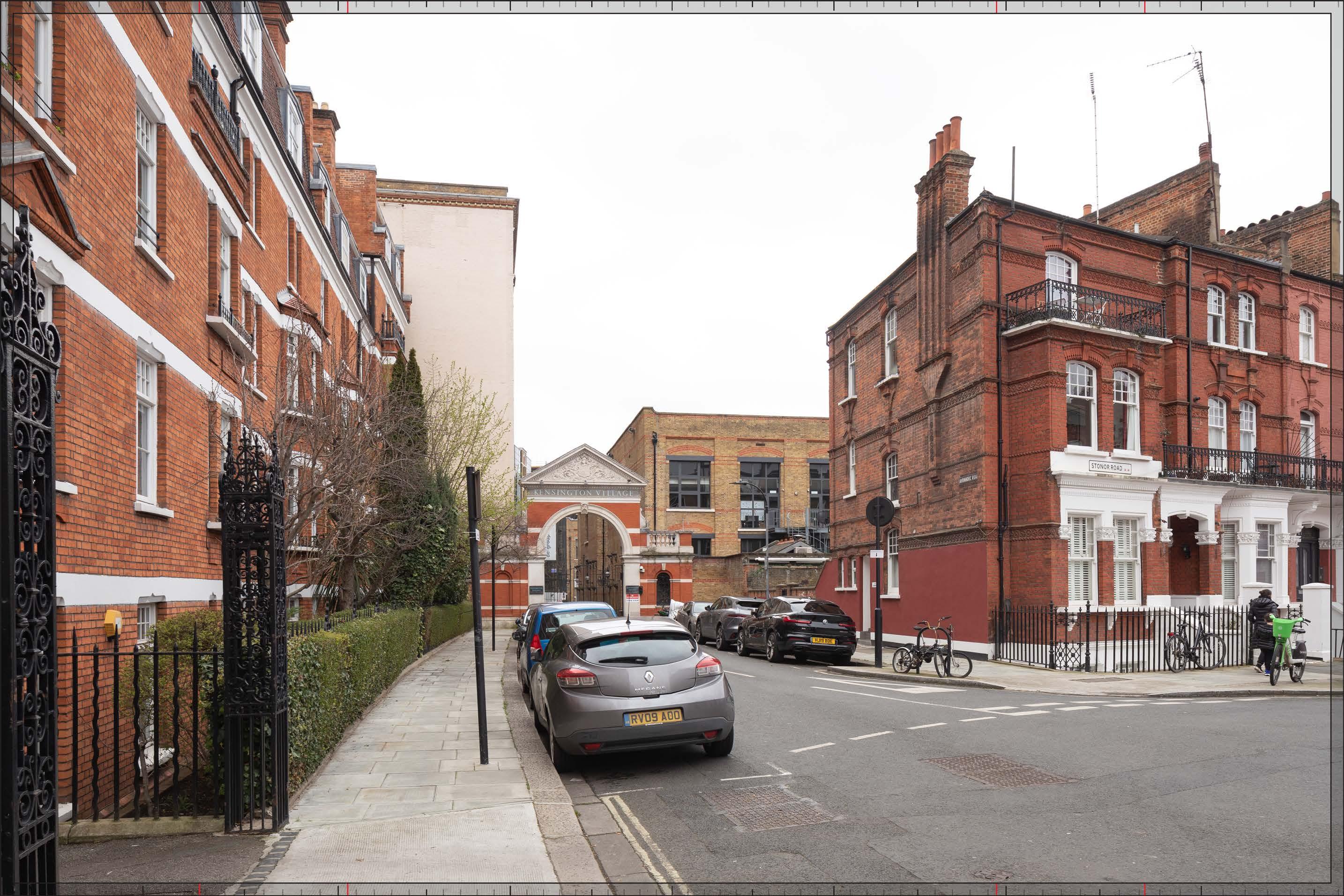
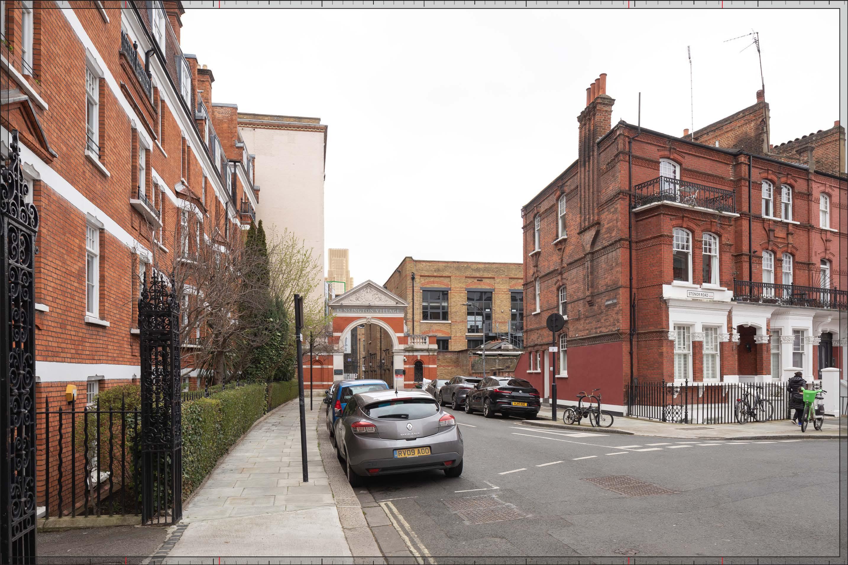
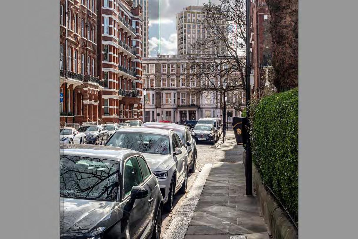
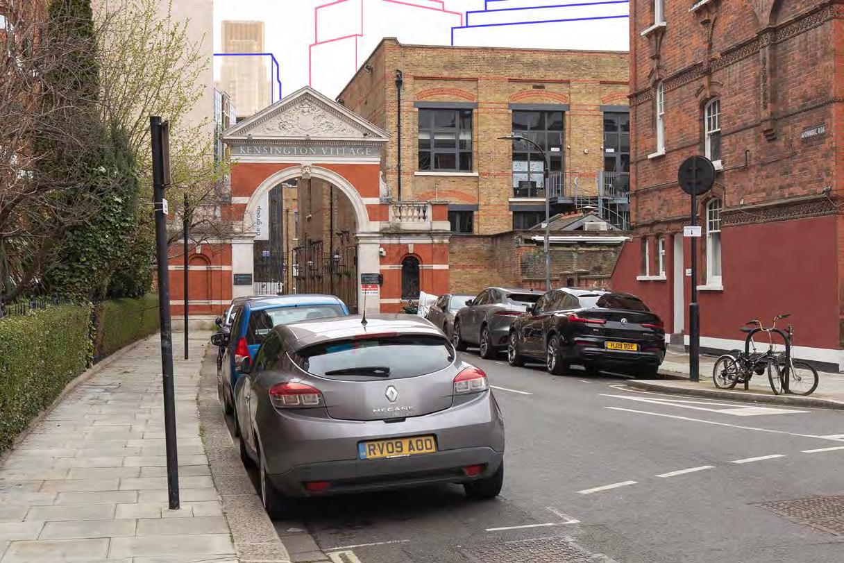
Avonmore Road, east pavement outside Nos. 1-42 Avonmore Gardens
Seagrave Road
Gardens, east pavement near centre of crescent
Place View B17 South Bank/St Pauls School
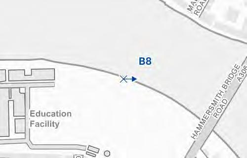
B8 Mund Street View B18
B16
Court Road
B19
Road
Philbeach
Lanfrey
Barons
Thaxton
View B20
Road, west of North End Road junction
Lille
Propose this is in the main body of the TVIA but a wireline. View 05 shows similar townscape and visual impacts and
to St Cuthbert's church. A 50mm landscape lens would not capture the fleche of the church which is a key townscape and skyline feature in the view and important to see and understand fully to assess the townscape and visual effects of the proposal. Propose this view is a wireline as
A15 16B Philbeach Gardens - opposite St Cuthberts Church
size needs justification "A 35mm portrait view is proposed to capture part of church in the foreground to understand the context surrounding clergy house and the relationship between the two listed buildings.
Propose this is included in a supplementary appendix as the view is more important for the Heritage Assessment (by Montagu Evans). Propose this is wireline as only Outline plots will be visible. " 27 R2 Philbeach Gardens,
size needs justificationA 35mm portrait view is proposed to sufficiently capture the proposed development. A 50mm lens would capture very little of the proposed development above the foreground terrace and not allow an appropriate assessment of the townscape and visual effects.
lens required to sufficiently capture the proposed development. A 50mm lens would capture very little of the proposed development above the foreground terrace and not allow an appropriate assessment of the townscape and visual effects. Wireline proposed as the visible plots are in Outline. Proposed that this view is placed in an appendix as it is supplementary to View R2 which is located on the opposite side of the road from which there is greater visibility of the proposed development. "
"TEST again.
Propose the lens is changed to 35mm to sufficiently capture the tops of the tallest buildings and better represent the impact on the skyline. Is a 50mm shift possible??"
Lens size needs justification "The viewpoint lies in close proximity to the site and the Square is enclosed by a 5-storey terrace. A 24mm is required to sufficiently capture the context and sky above the terrace to be able to illustrate that the proposed development would be visible on the skyline in the background.
Propose that this view is included in an appendix and as a wireline, as it is located in a private garden and is more relevant for the Heritage Assessment (by Montagu Evans). An assessment of the effects on townscape and visual receptors is sufficiently covered in the main body of the TVIA by View 17A. Requested as render by RBKC 31/01/24. "
We will move the position slightly further back along the road to ensure that the top of the tallest building is fully captured.
Can we stitch the canvas to add more sky and capture the top? Move back to building line?
Proposed wireline and appendix - largely screened by trees, principally Outline plots, distant
Proposed wireline and appendix - supplementary to View 21B and from same conservation area. Assessment of effects of townscape and visual receptors sufficiently covered by View 21B.
Proposed wireline as Outline Plots principally visible. Tallest tower (Detail) also visible but less so and townscape and visual effects of the architectural design of the tallest building is sufficiently covered by View 23. 20
Proposed that this view is placed in an appendix as it is supplementary to View 27B which will be in the main body of the TVIA - townscape and visual receptors are the same. "
Proposed wireline as Outline Plots principally visible. Tallest tower (Detail) also visible but less so and townscape and visual effects of the
Propose this view is a wireline as only Outline plots will be visible. "
Propose
which allows a sufficient assessment of effects on the townscape and visual receptors."
D.
and visual receptors.
50mm
Propose this is a non-verified
by Montagu Evans.
and included in an
given the significant screening of foreground winter trees which greatly limit any visibility Townscape and visual effects from this area sufficiently covered by View
Propose
Propose this is wireline due to considerable distance of the viewpoint and limited visibility of the proposed development due to foreground winter trees.
Appendix G
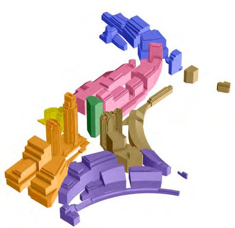
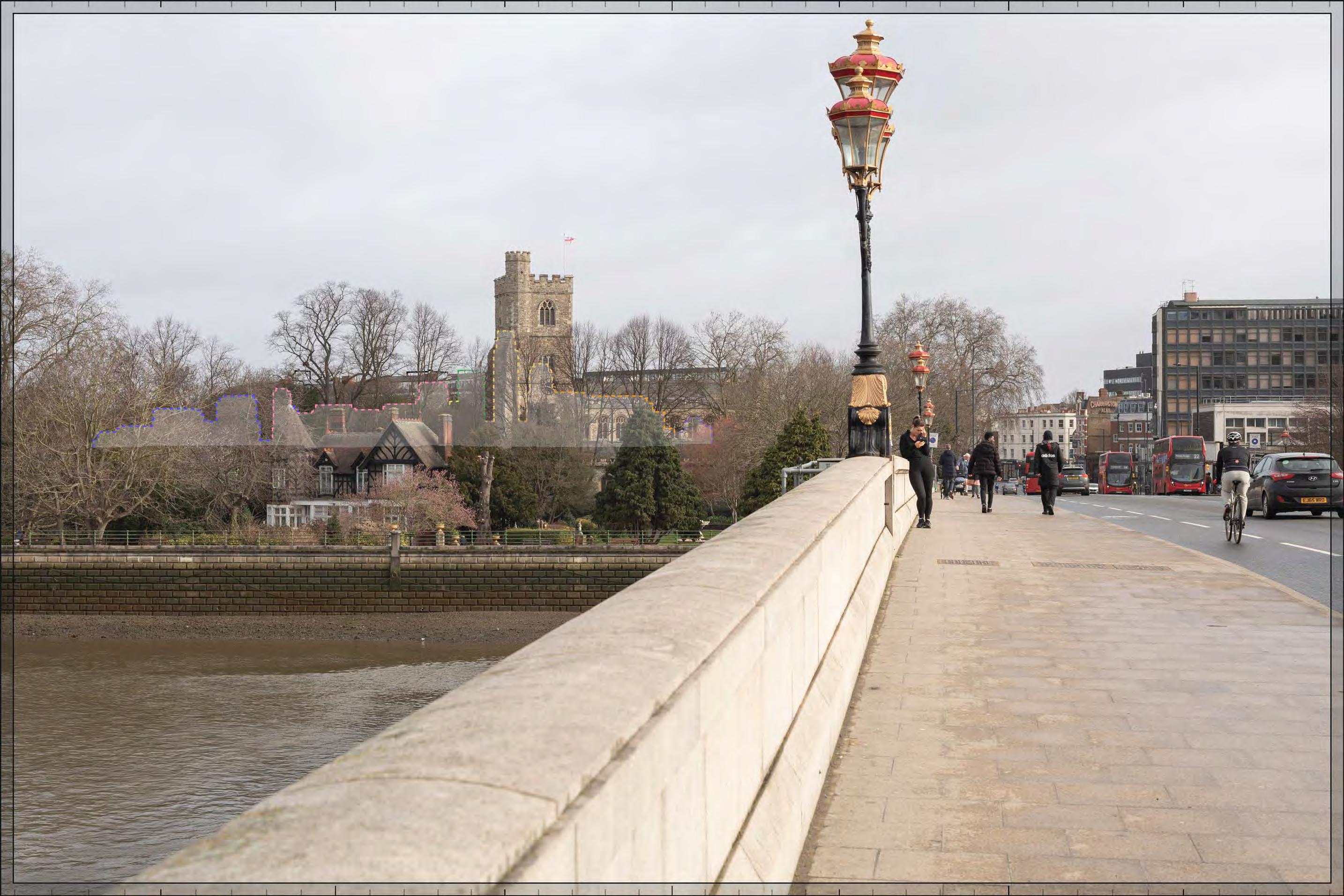
Zone Of Visual Influence
A ZVI (Zone of Theoretical Visibility) Study provides a visual representation of potential scheme visibility at 1.6m from the ground.
It is classed as “theoretical” due to the unreliable nature and limited accuracy of the commercially available context models and DSM provided to us by external sources.
While due care has been taken to use relevant information as available to us, we cannot guarantee its accuracy.
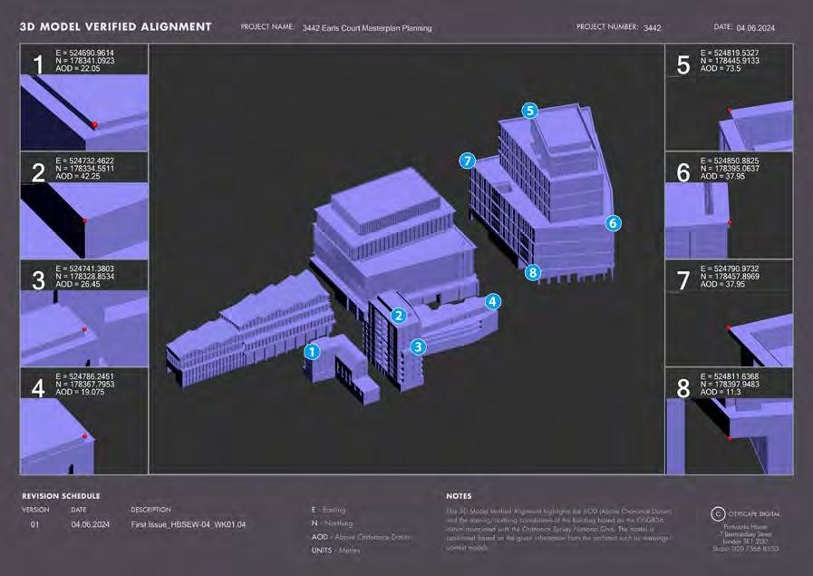
This report has been produced by Cityscape Digital using Zmapping and Environment Agency’s LiDAR DSM & DTM data (100cm). The proposed models used show that of the Early Phases Plots and comparatively, All plot development thus far.
The ZVI study on the Zmapping area was produced without trees and consented developments taken into consideration.
In the areas where LiDAR DSM & DTM data was used, the trees were included in the Viewshed calculations, due to the format of the data received (there is no workflow that can separate the trees from the buildings).
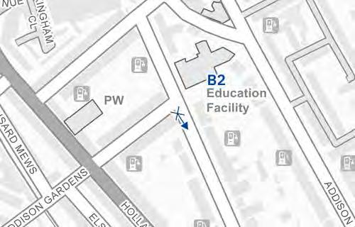
Early Phases ZVI overlaid with agreed viewing positions
Analysis has been based on 3D Zmapping data and LiDAR DSM & DTM data.
Preliminary, model-based work is only as accurate as the 3D information provided and so we recommend all decisions based on massing are checked using Accurate Visual Representations.
All Phases ZVI overlaid with agreed viewing positions
Appendix H
Visualiser’s Methodology: Accurate Visual Representations
Table of views (continued)
Table of views (continued)
2.0 Introduction
2.0.1 Methodology overview
The methodology applied by Cityscape Digital Limited to produce the ‘Type 4 Photomontages survey / scale verifiable’1 or views contained in this document are described below. In the drafting of this methodology and the production and presentation of the images, guidance has been taken from the ‘TGN 06/19 Visual Representation of development proposals’ (TGN06/19) from the Landscape Institute published on 17 September 2019 in support of GLVIA3.
The disciplines employed are of the highest possible levels of accuracy and photo-realism which are achievable with today’s standards of architectural photography and computer-generated models.
2.0.2
View selection
The viewpoints are selected through a process of consultation with relevant statutory consultees by townscape/heritage consultants and having regard to relevant planning policy and guidance.
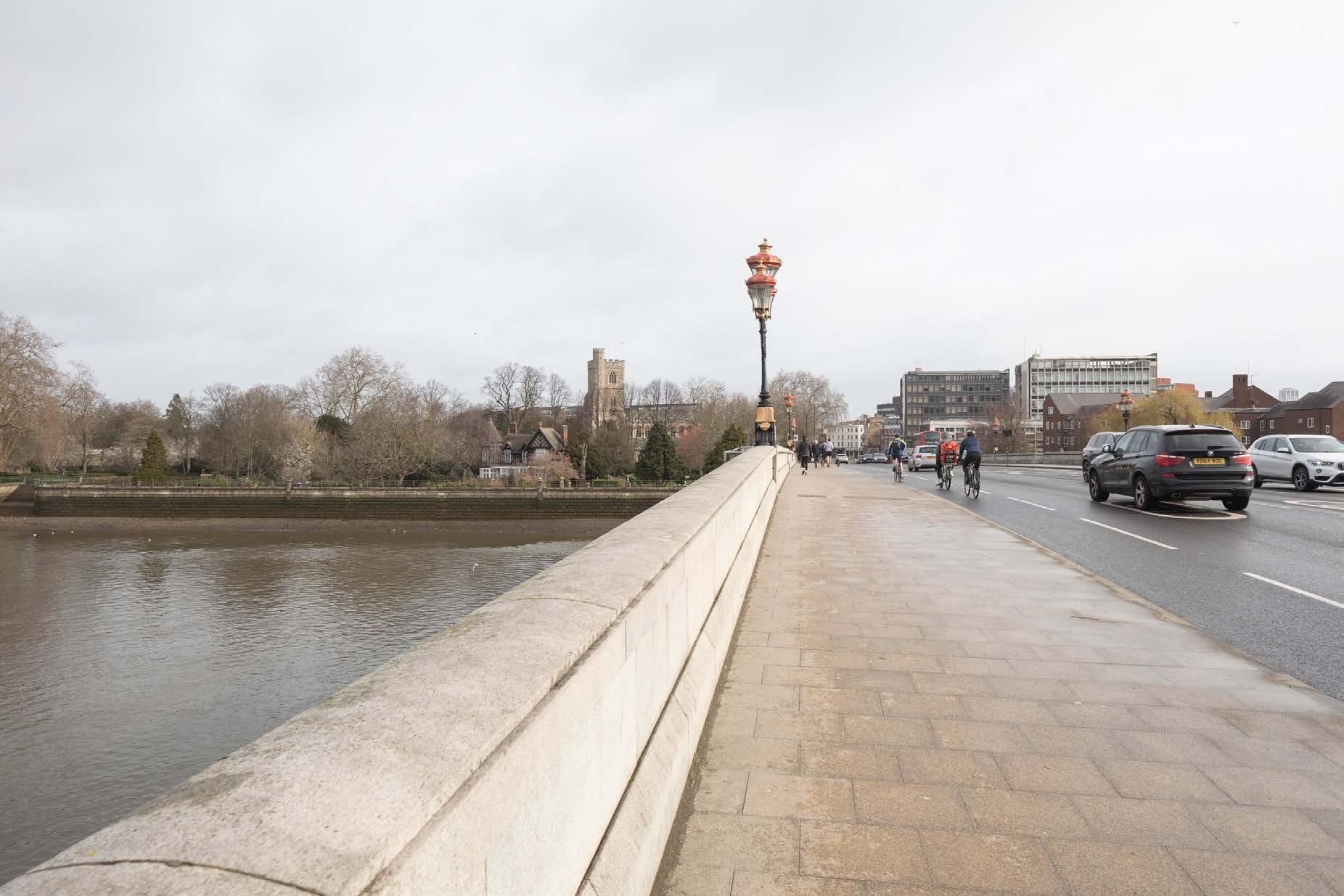
2.1 Photography
2.1.1 Digital photography
High quality digital full frame sensor cameras are being utilised.
2.1.2 Lenses
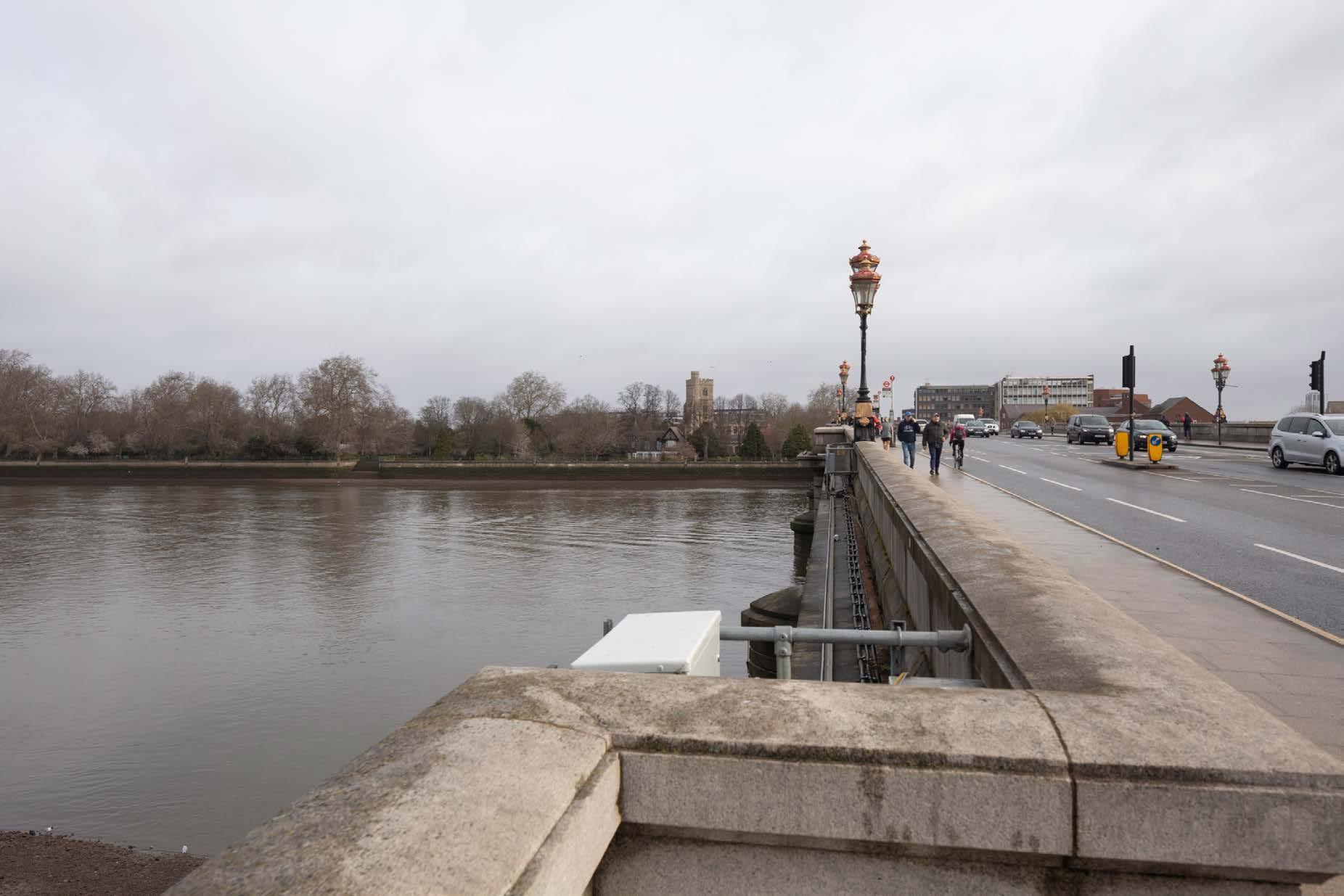
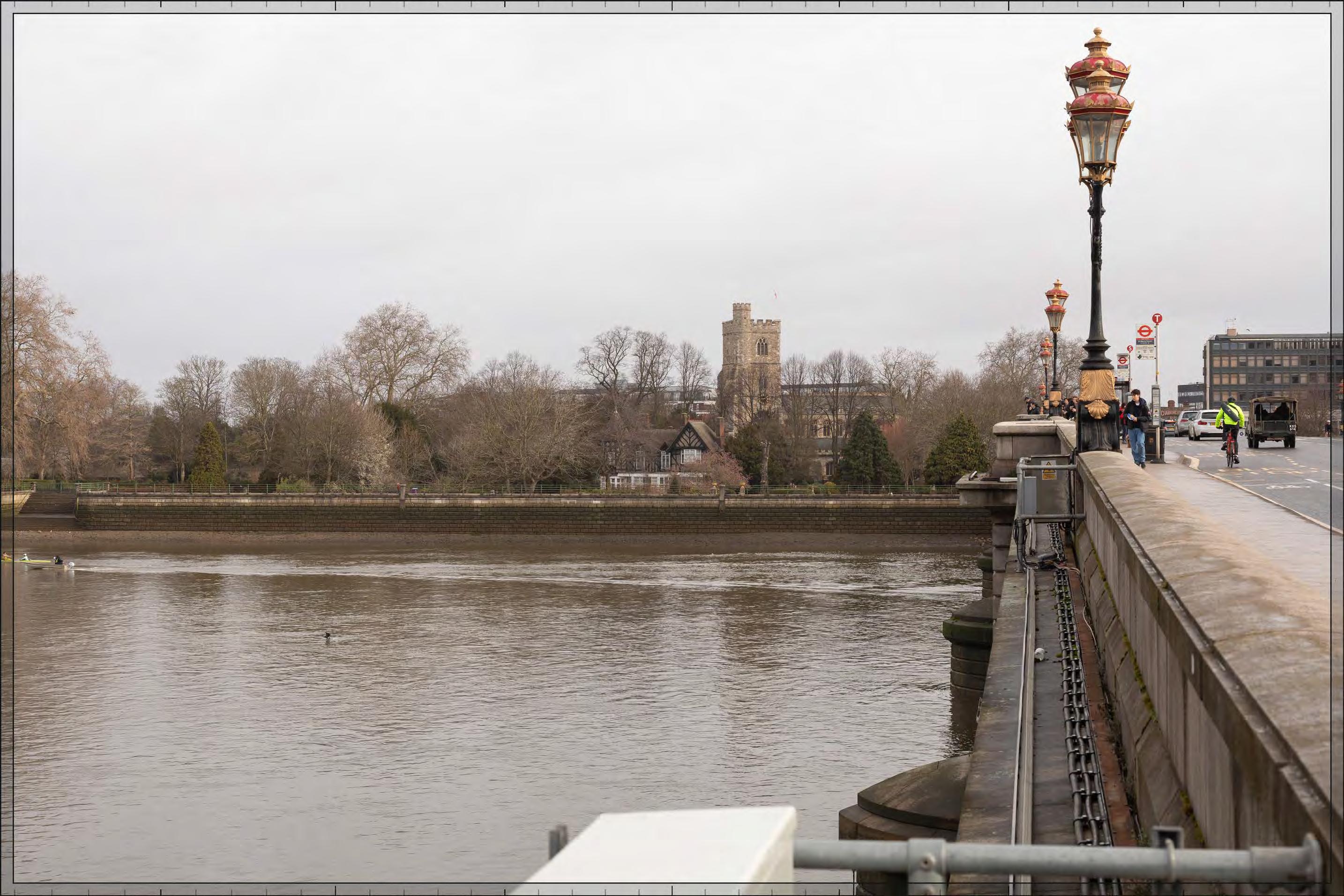
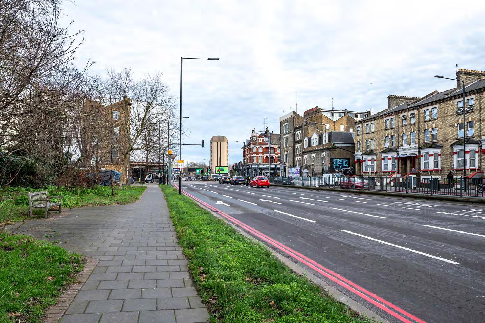
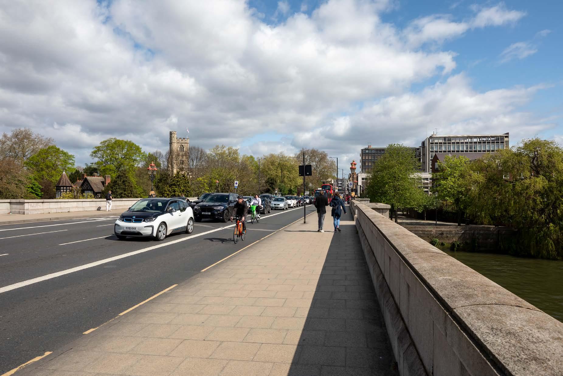
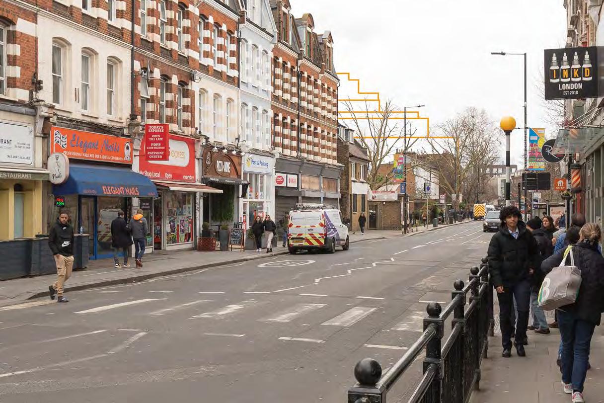
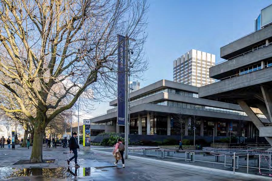
In accordance with TGN 06/19, Cityscape balances the need to include the extent of the site and sufficient context with the stated preference for 50mm lenses. For local urban views a wide angle lens of 24mm or 35mm is generally used. For more open spaces the default is 50mm, intermediate distance views are photographed with a lens between 35mm to 70mm and occasionally long range views may be required with lens options ranging from 70mm to 1200mm.
As a guide, the following approach is used:
View Lens options
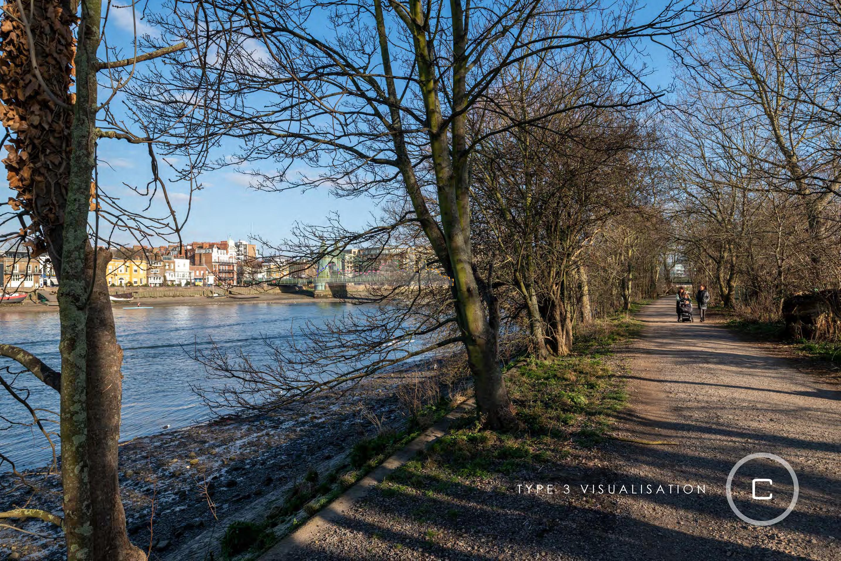
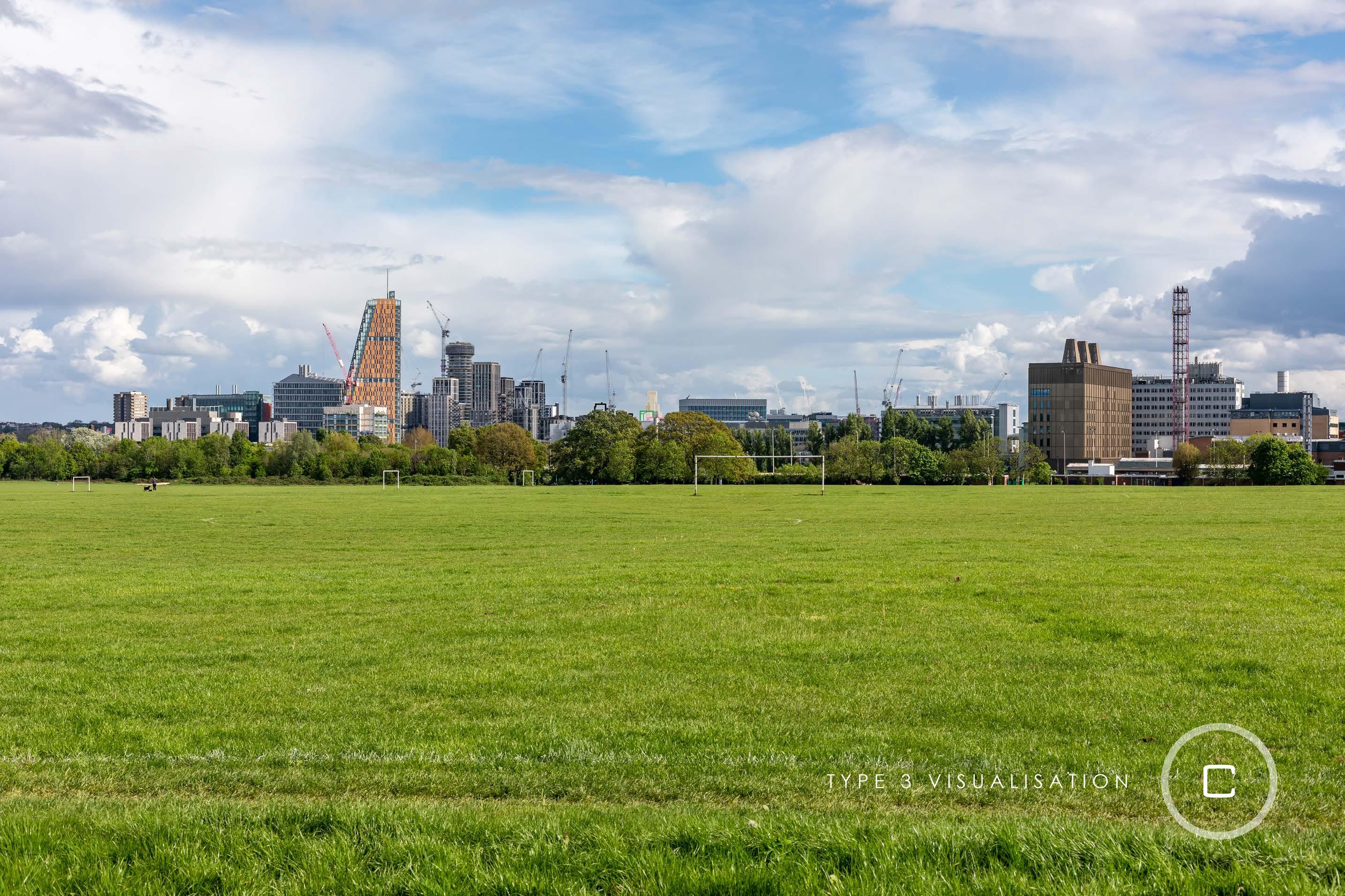
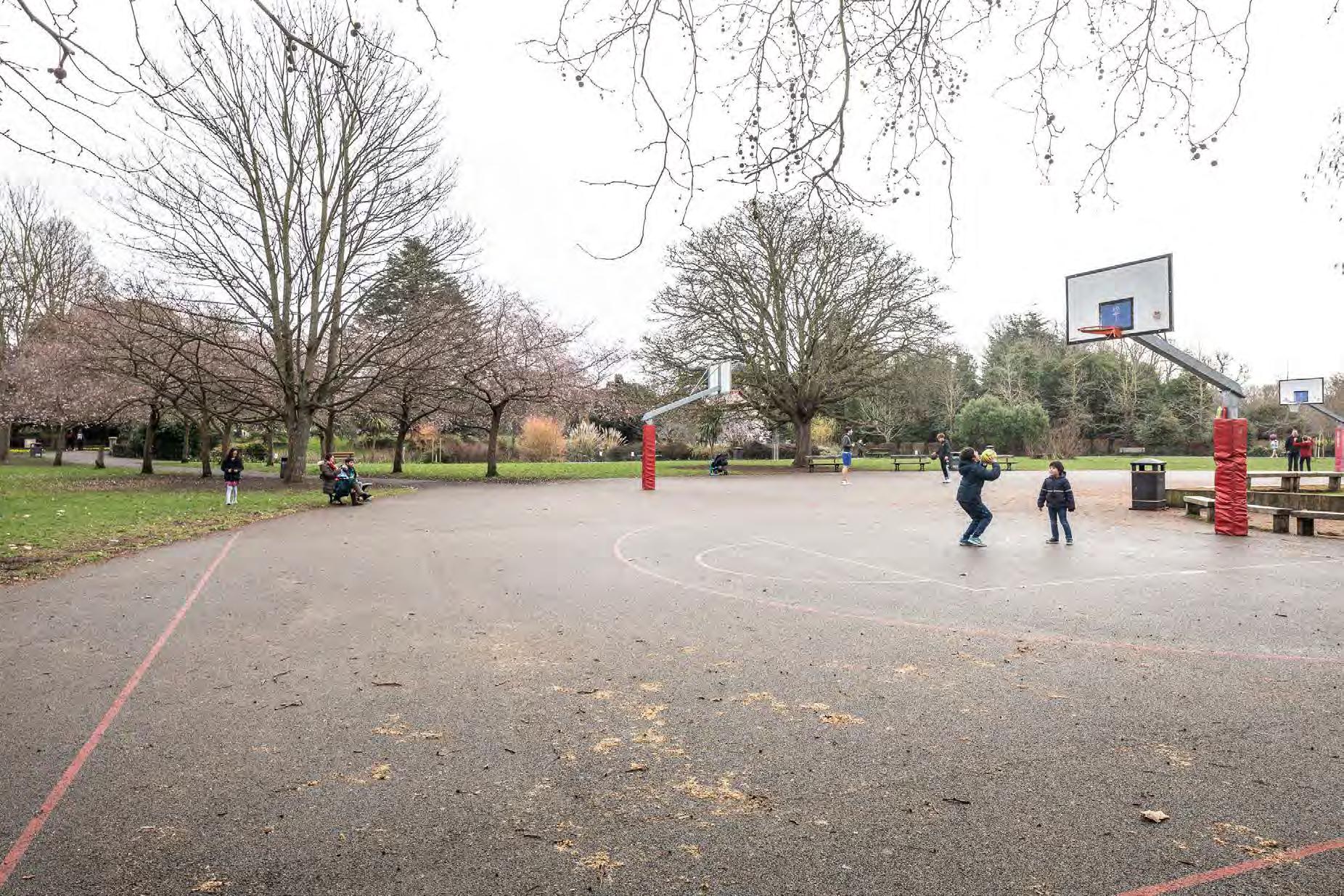
Relevant foreground, urban context or large site 24mm – 35mm
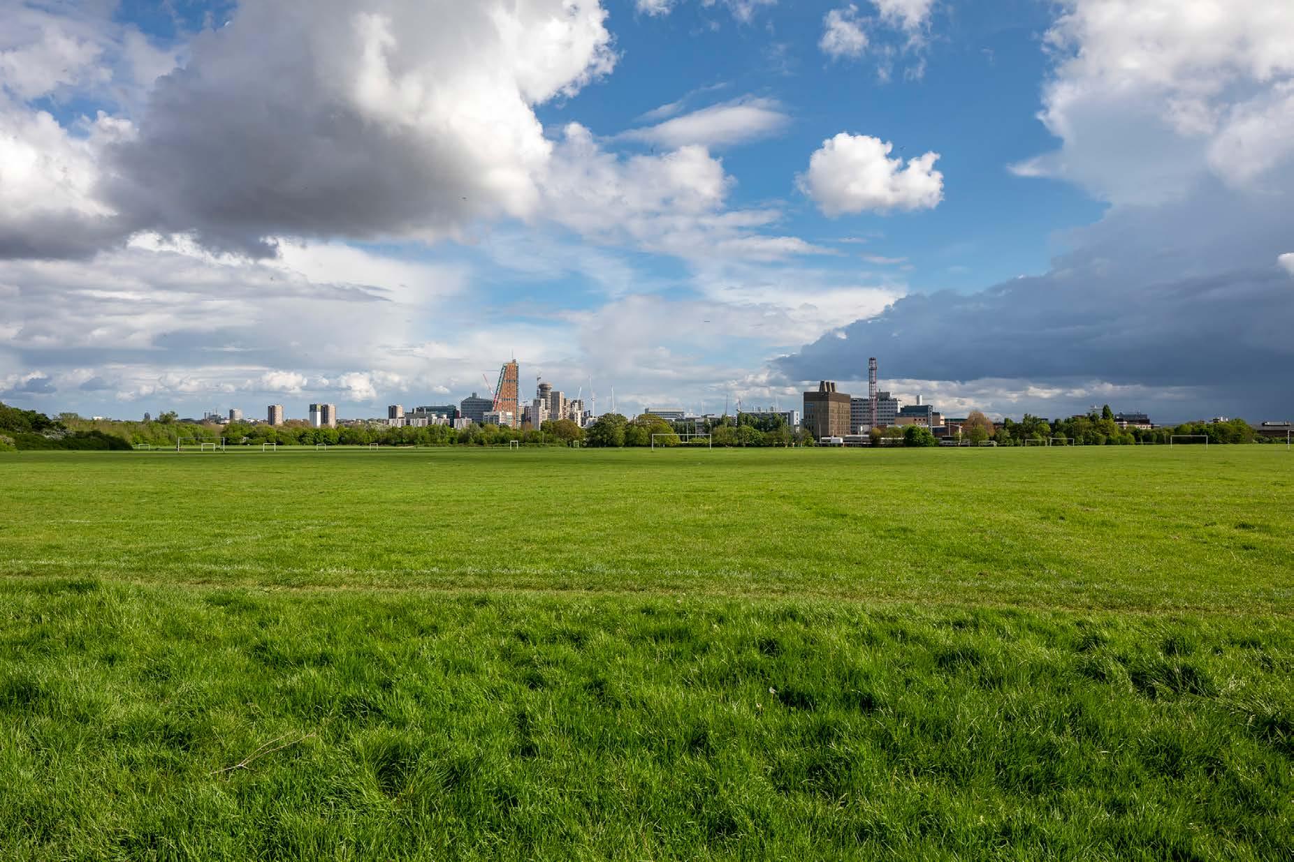
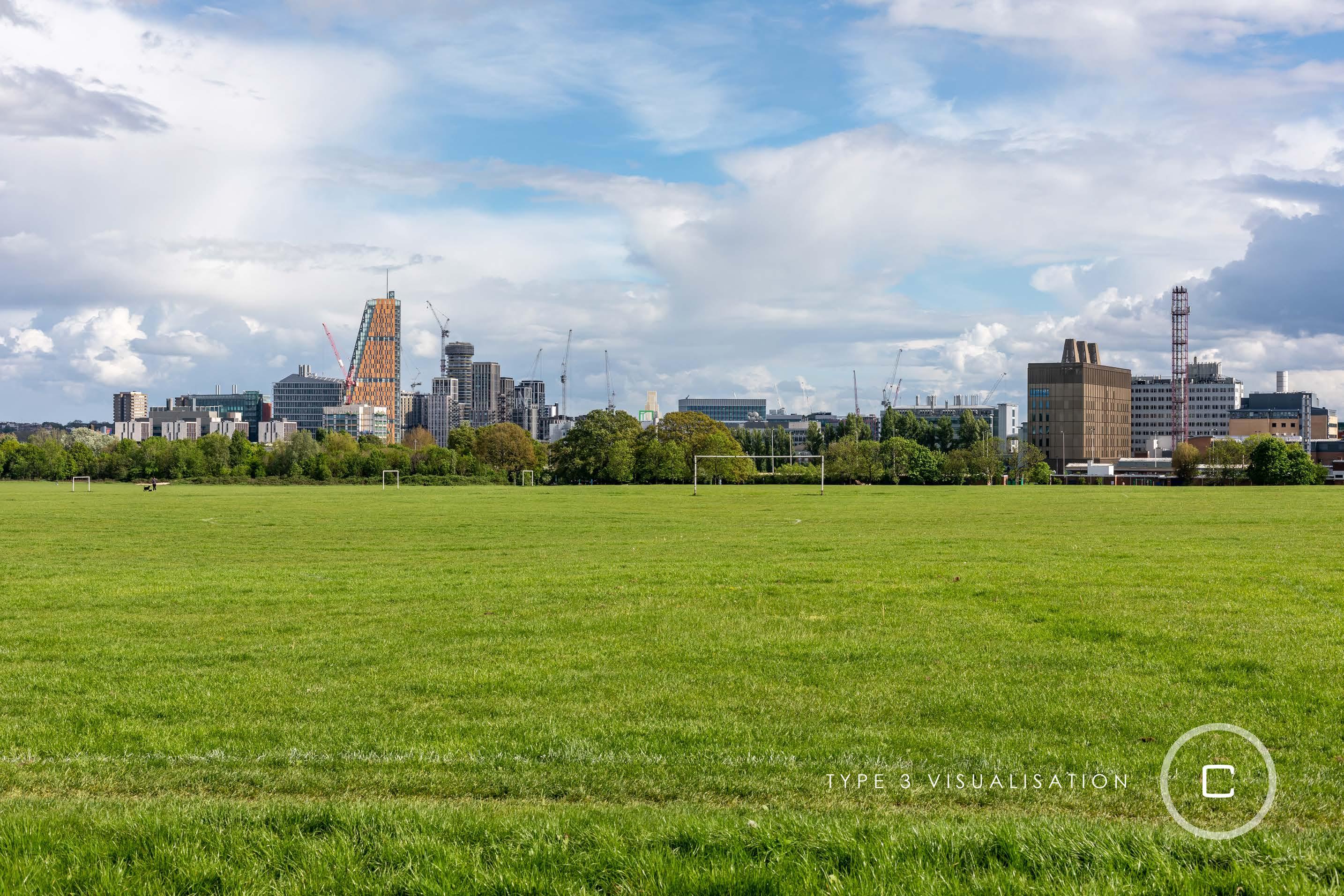
Open spaces, where proposed development can be included 50mm
800 to 5000 metres – intermediate 35mm – 70mm 5000+ metres – long 70mm – 1200mm
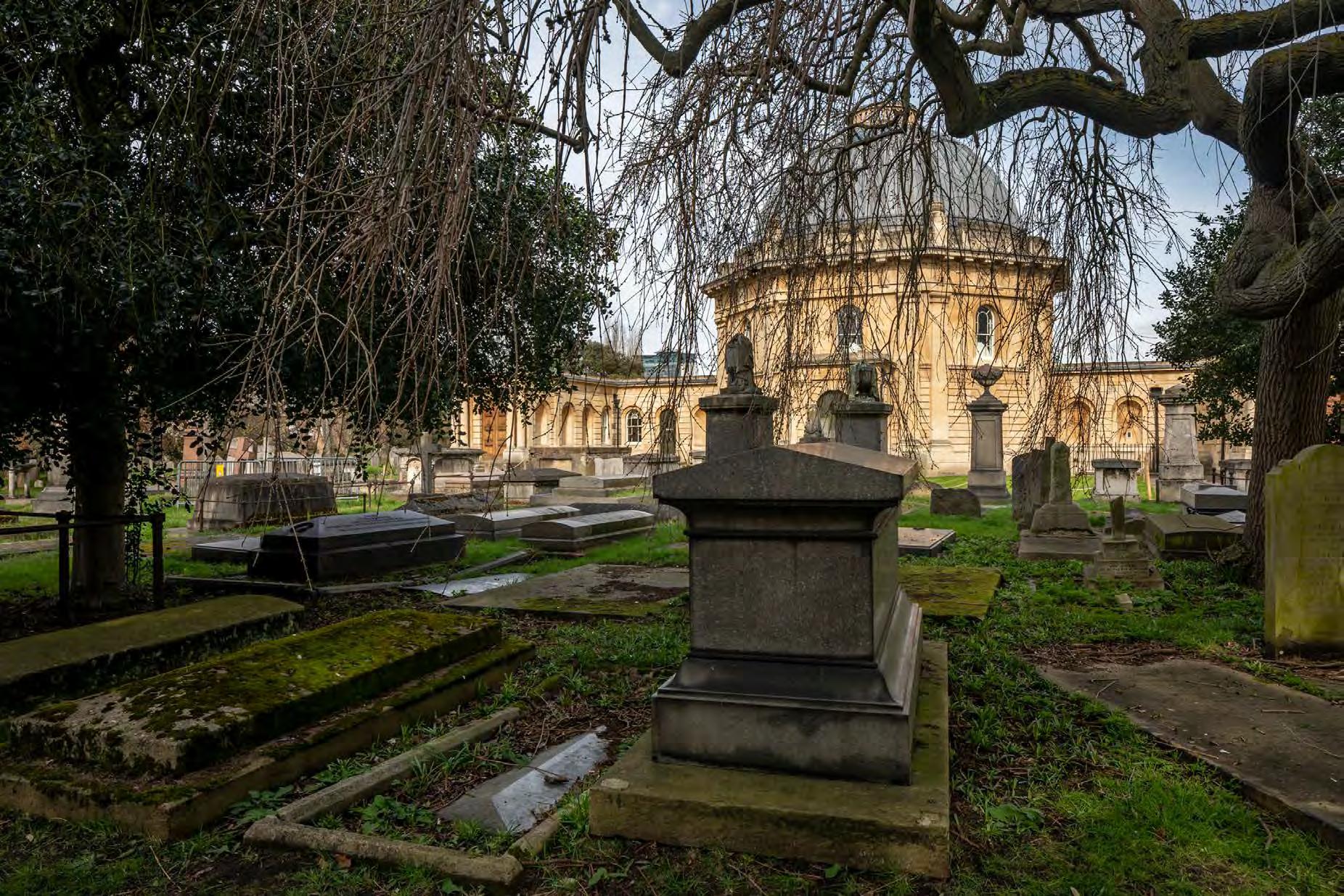
Examples of these views are shown in Figures H.1 and H.2.
2.1.3 TGN 06/19
States that:
“2.2 Baseline photography should: [...] include the extent of the site and sufficient context;”2
“1.1.7 If a 50mm FL lens cannot capture the view in landscape or portrait orientation (for example, if the highest point of the development is approaching 18° above horizontal) the use of wider-angled prime lenses should be considered, working through the following sequence of fixed lenses in this order: 35mm FL > 28mm FL > 24mm FL > 24mm FL Tilt-Shift. Tilt-Shift Lenses are considered at Appendix 13. In these unusual situations, the reasoning for the choice and the approach used should be documented, and the agreement of the competent authority should be sought (see Appendix 10 Technical Methodology).”3 and
“Views should include the full context of the site / development and show the effect it has upon the receptor location.[...]”4
2 TGN 06/19 Visual Representation of development proposals.’
Available at: https://landscapewpstorage01.blob.core.windows.net/www-landscapeinstitute-org/2019/09/ LI_TGN-06-19_Visual_Representation.pdf
(Accessed: March 2022).pp. 5, Paragraph 2.2
3 TGN 06/19 Visual Representation of development proposals.’
Available at: https://landscapewpstorage01.blob.core.windows.net/www-landscapeinstitute-org/2019/09/ LI_TGN-06-19_Visual_Representation.pdf
2.1.4
Digital camera
Cityscape uses high quality professional DSLR (digital single lens reflex) and DSLM (digital single lens mirrorless) cameras. The cameras utilise FFS (full frame sensors) so declared focal lengths require no conversion to be understood in line with TGN 06/19 guidelines.
Cityscape use high quality lenses that are matched to the resolution of the cameras to ensure high contrast and sharp rendition of the images.
2.1.5
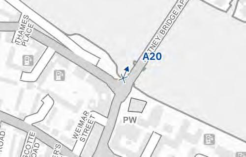
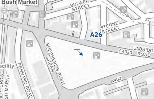
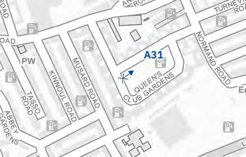
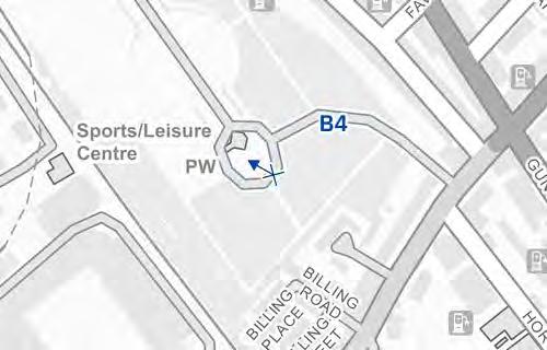
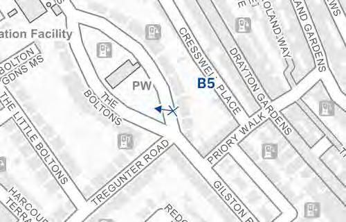
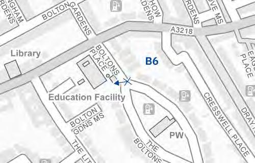
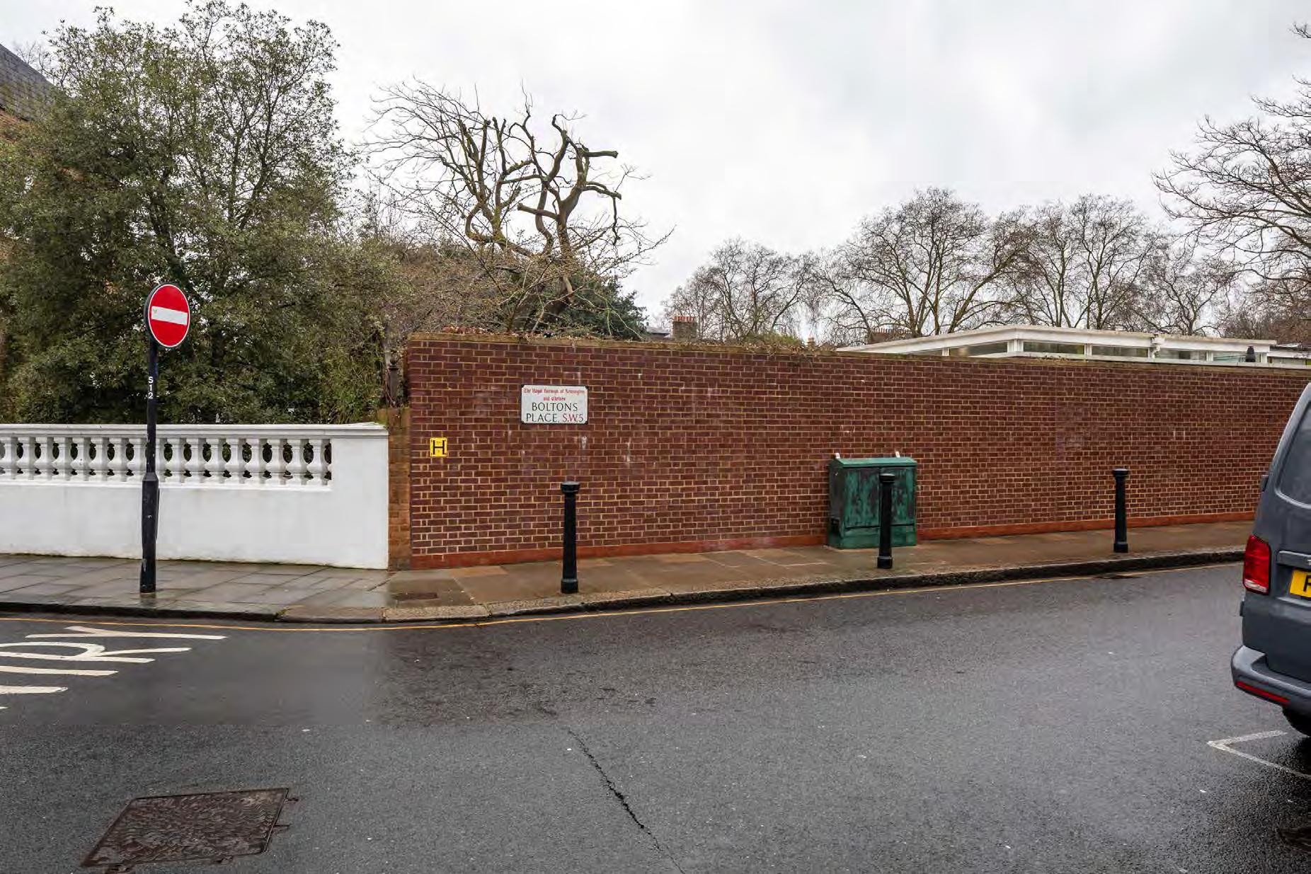
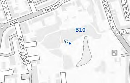
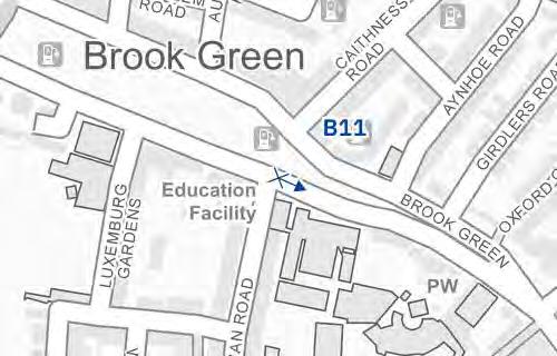
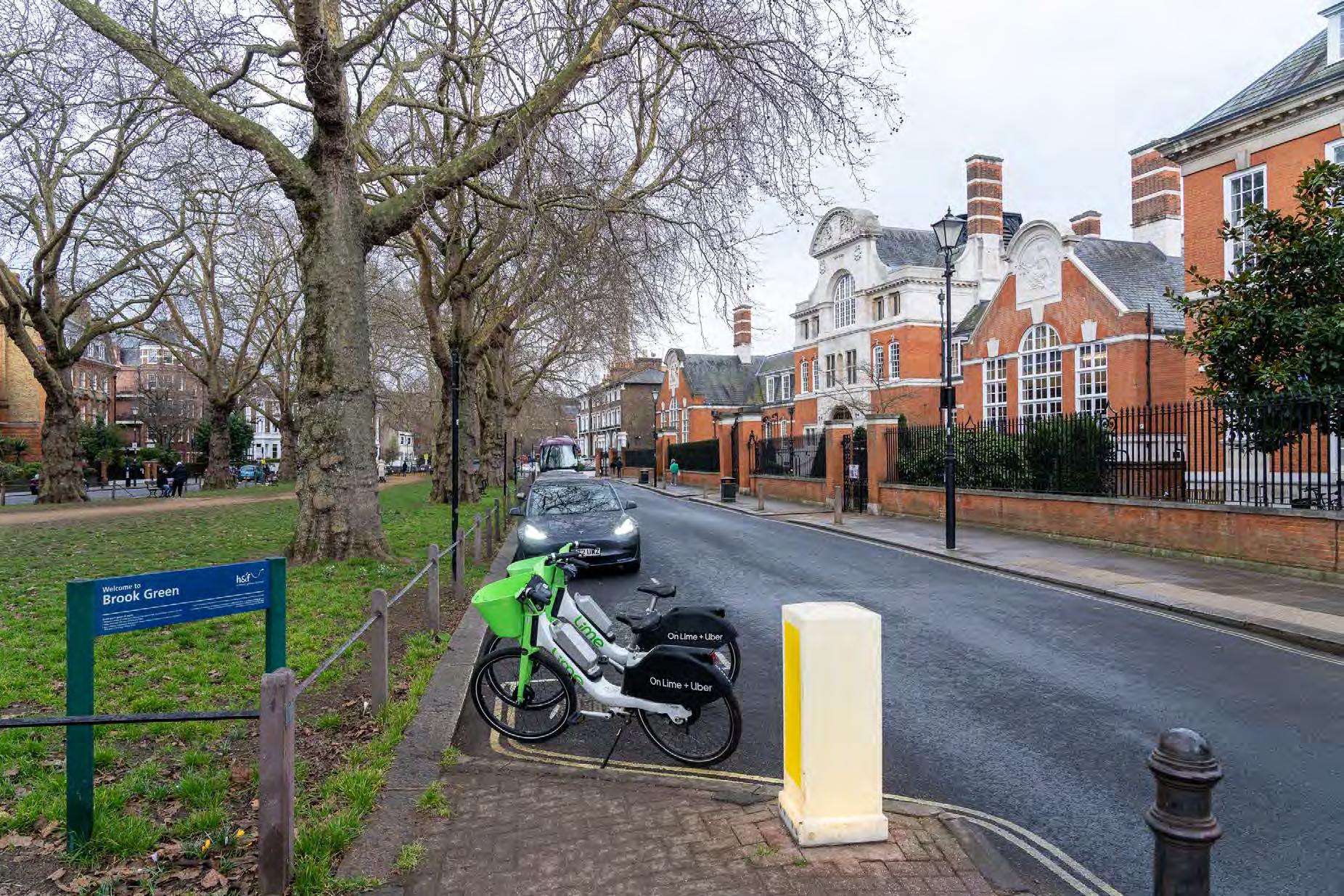
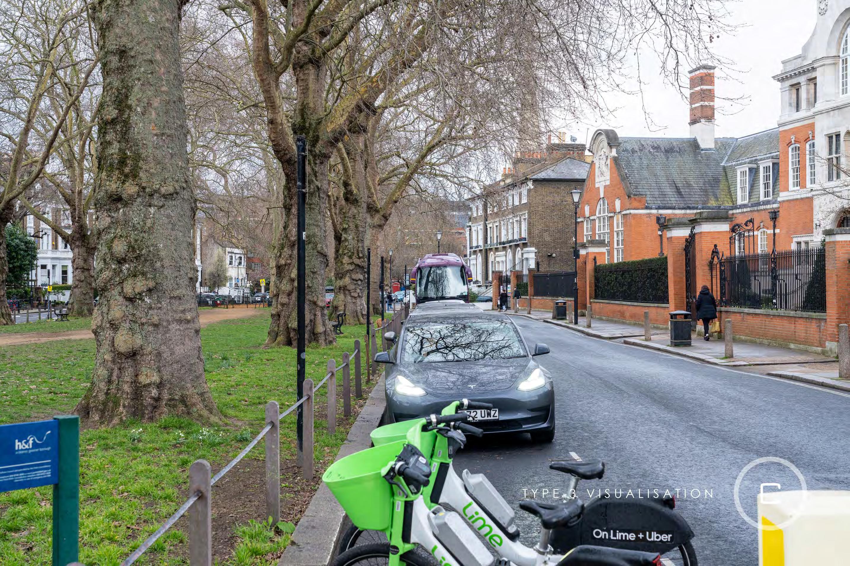
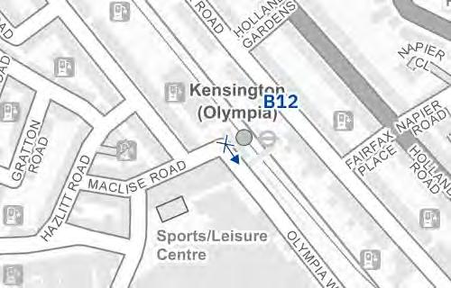
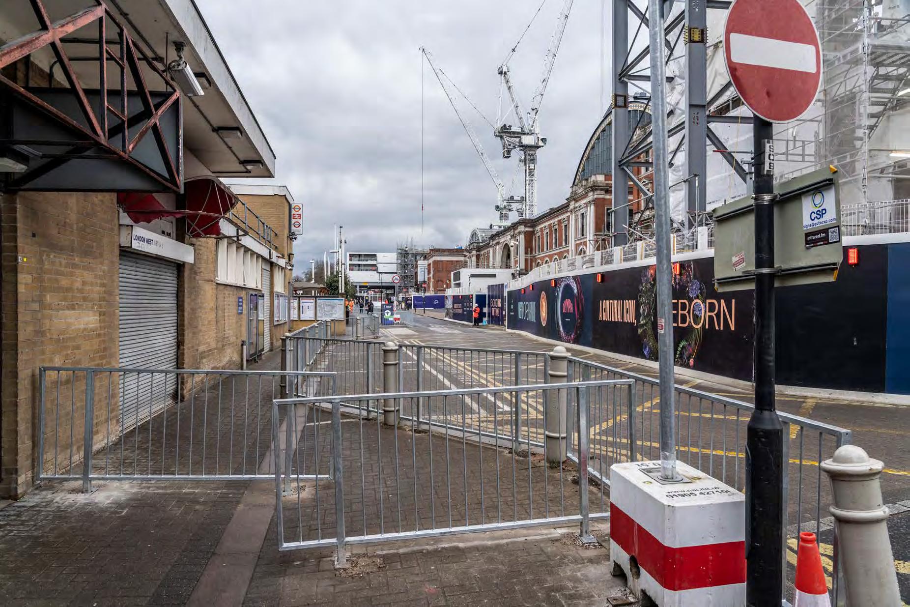
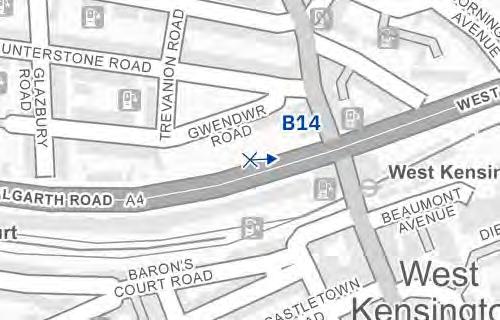
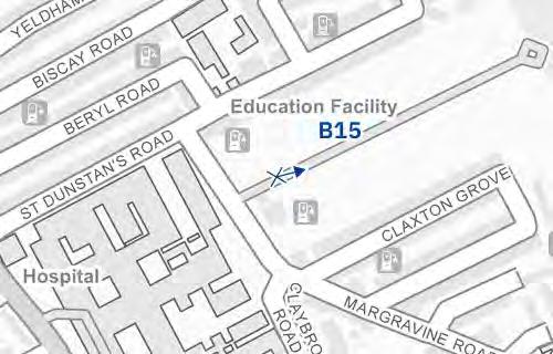
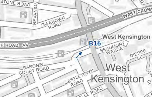
Position, time and date recording
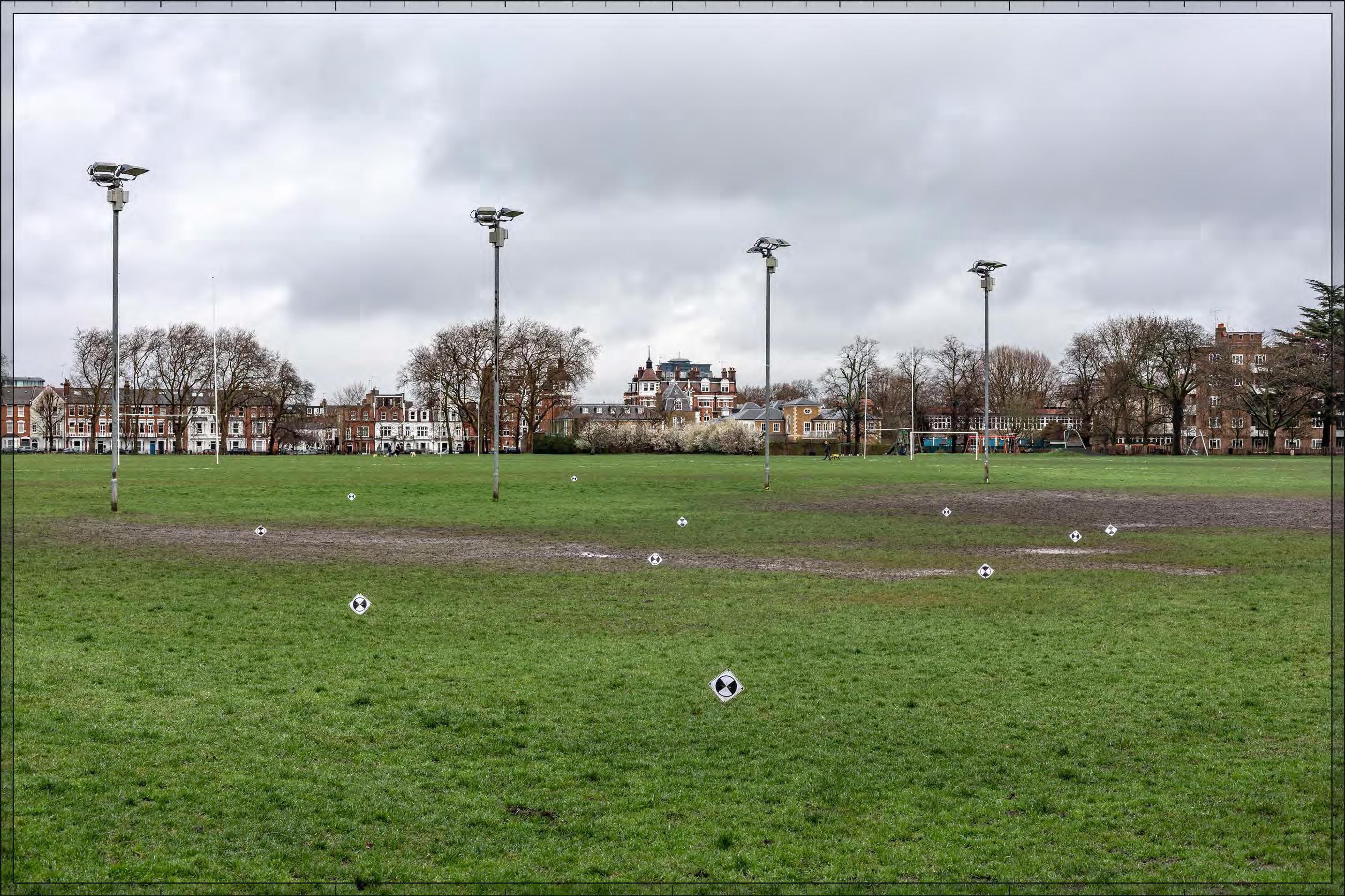
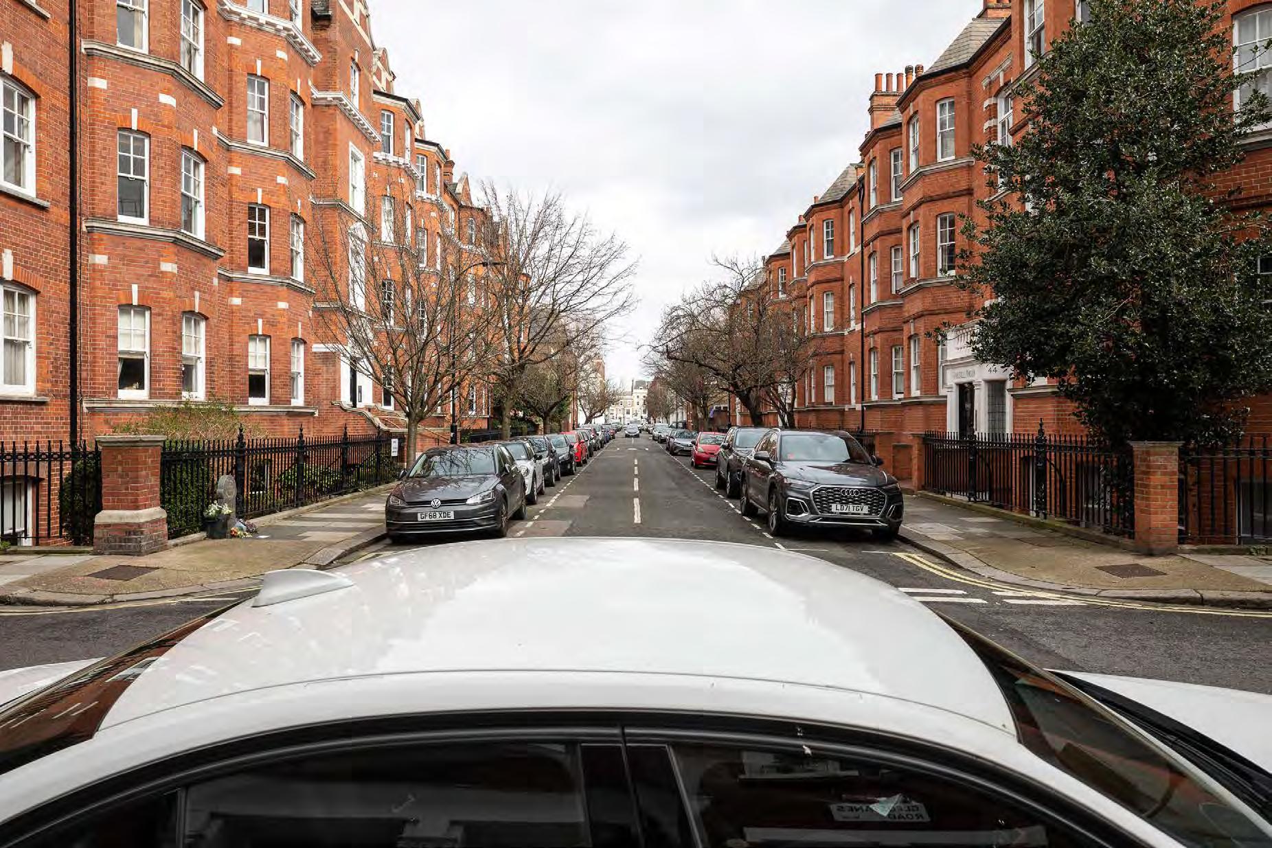
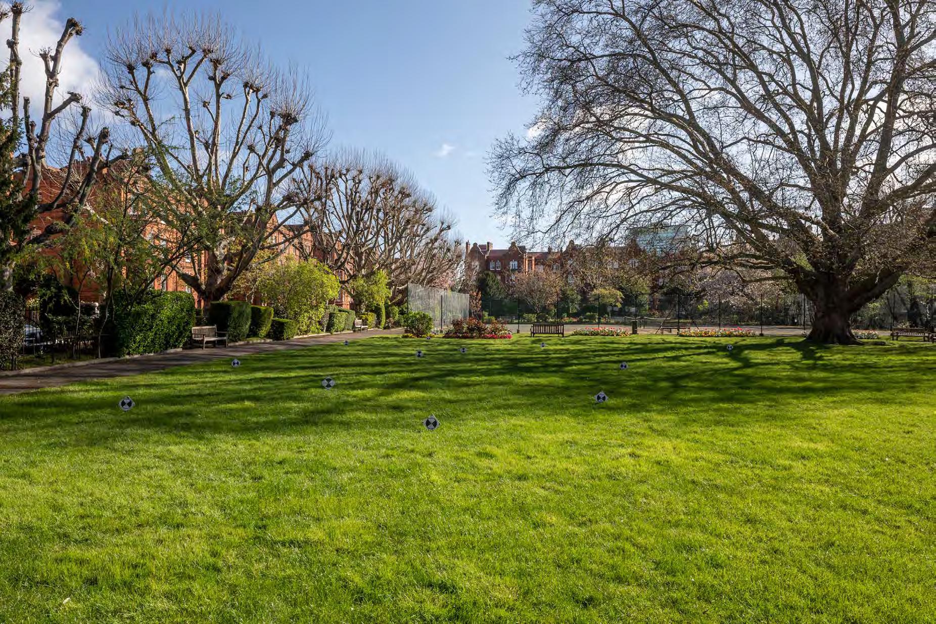
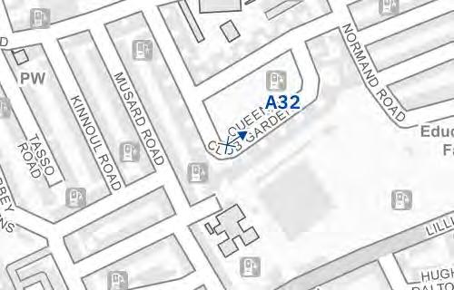
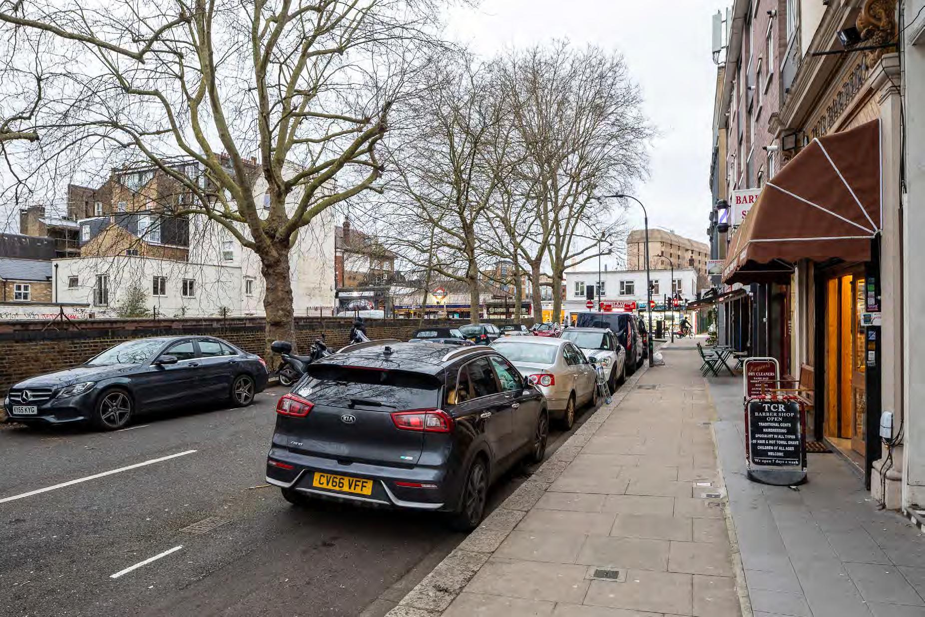
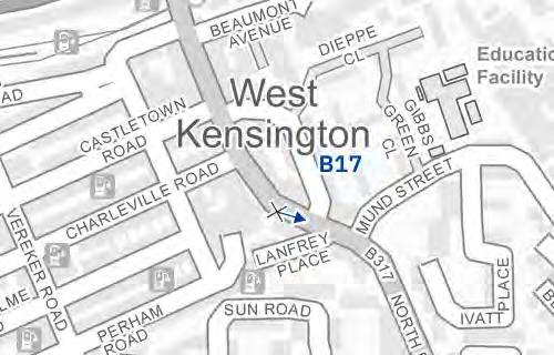
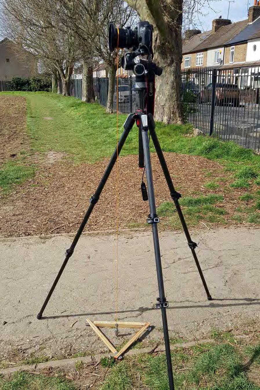
The photographer is provided with (i) an Ordnance Survey map or equivalent indicating the position of each viewpoint from which the required photographs are to be taken, and (ii) a digital mockup rendered with a context model of the desired view. For each viewpoint the camera is positioned at a height of 1.60 metres above the ground level which closely approximates the human eye altitude, and falls into the 1.5-1.65m range provided by TGN 06/195
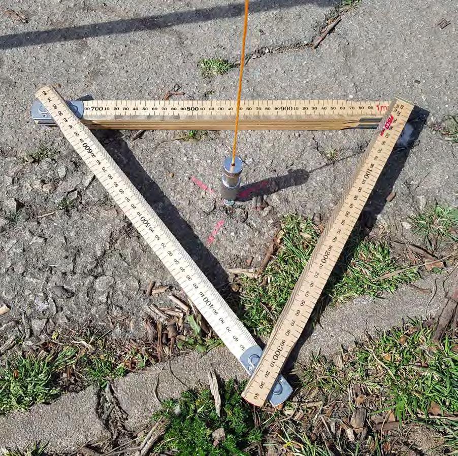
If local conditions required a deviation to capture the view, the exact height can be found in the Table of Views. A point vertically beneath the entrance pupil of the lens is marked on the ground as a survey reference point and two digital reference photographs are taken of (i) the camera/tripod location and (ii) the survey reference point (as shown in Figures H.3 and H.4). The date and time of the photograph are recorded by the camera.
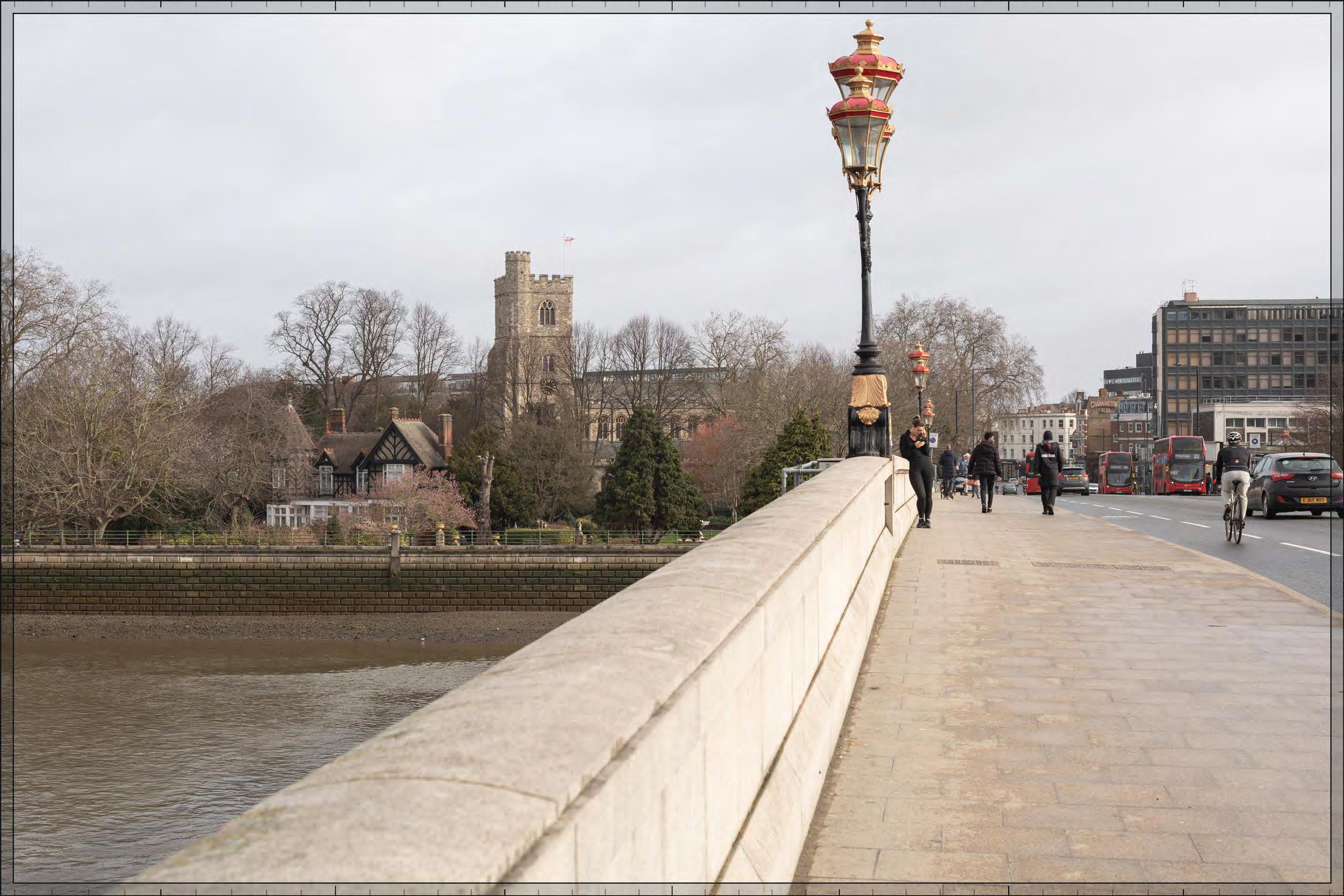
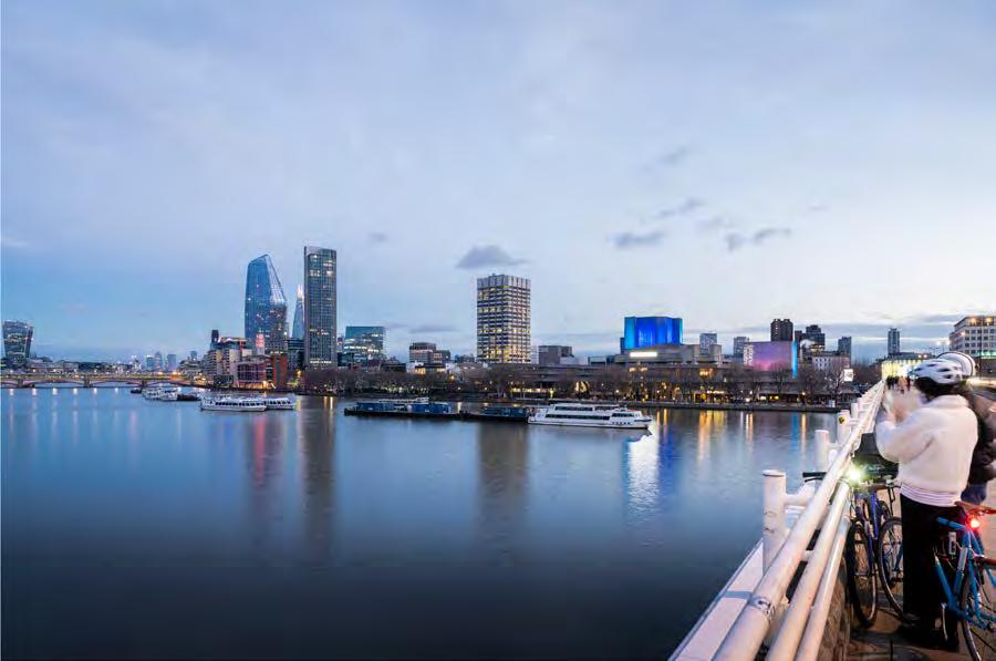
H.2: Intermediate view
1 ‘TGN 06/19 Visual Representation of development proposals.’ Available at: https://landscapewpstorage01.blob.core.windows.net/wwwlandscapeinstitute-org/2019/09/LI_TGN-06-19_Visual_Representation.pdf
(Accessed: March 2022).pp. 21-2
(Accessed: March 2022).pp. 28, Paragraph 1.1.7
4 ‘TGN 06/19 Visual Representation of development proposals.’
Available at: https://landscapewpstorage01.blob.core.windows.net/www-landscapeinstitute-org/2019/09/ LI_TGN-06-19_Visual_Representation.pdf
(Accessed: March 2022).pp. 35, Paragraph 4.1.5
5 ‘TGN 06/19 Visual Representation of development proposals.’ Available at: https://landscapewpstorage01.blob.core.windows.net/www-landscapeinstitute-org/2019/09/ LI_TGN-06-19_Visual_Representation.pdf (Accessed: March 2022).pp. 50
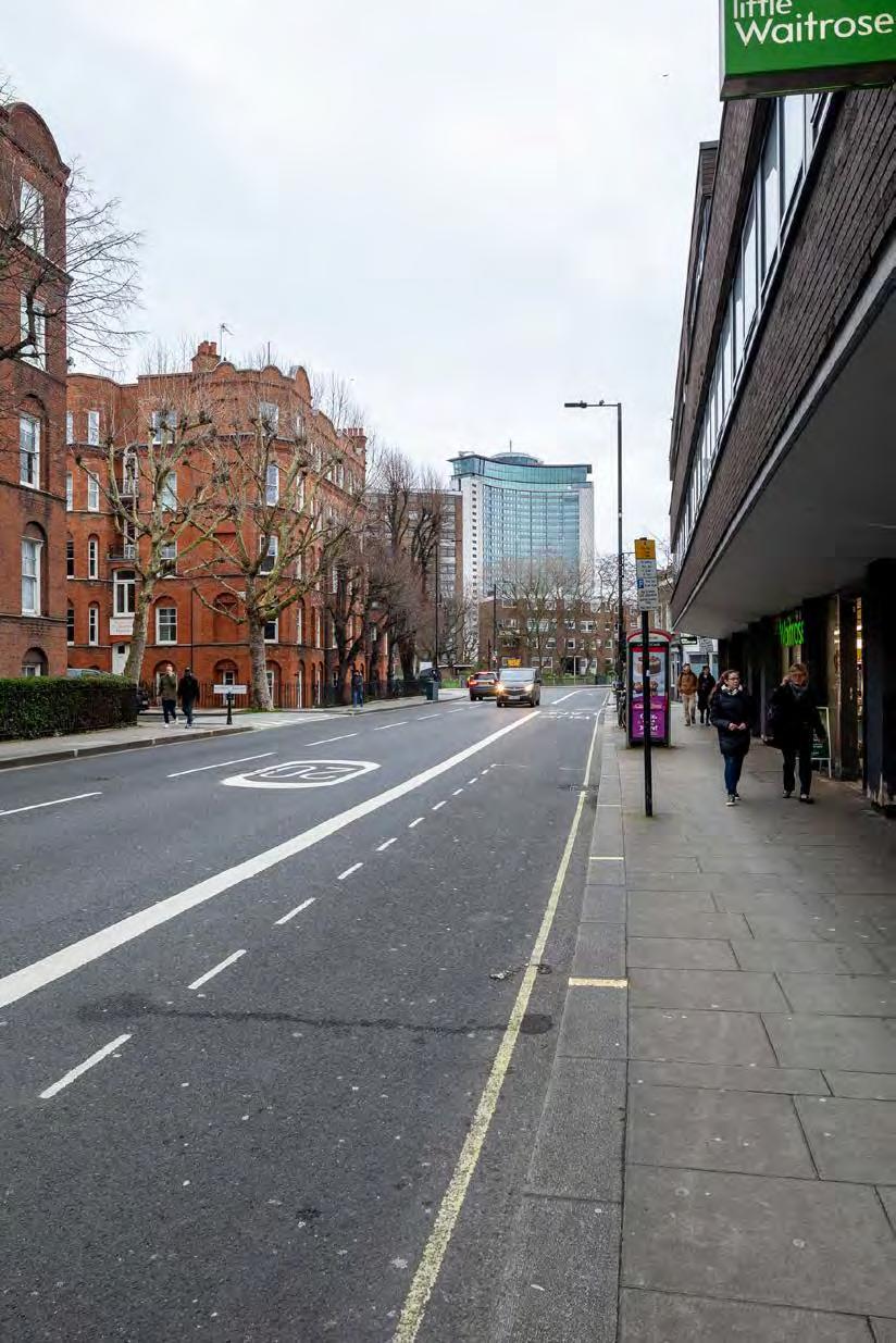
Figure H.1: Local view
Figure
Figure H.3: Camera location
Figure H.4: Survey reference point
H1.1 Photography (continued)
2.2 Digital image correction
2.2.1 Raw file conversion
Professional digital cameras produce a raw file format, which is then processed for both high detail and colour accuracy. The final image is saved as an 8 bit tiff6 file.
2.2.2 Digital image correction
The digital photographs were prepared for the next stage of camera matching (see Sections H.6 and H.7).
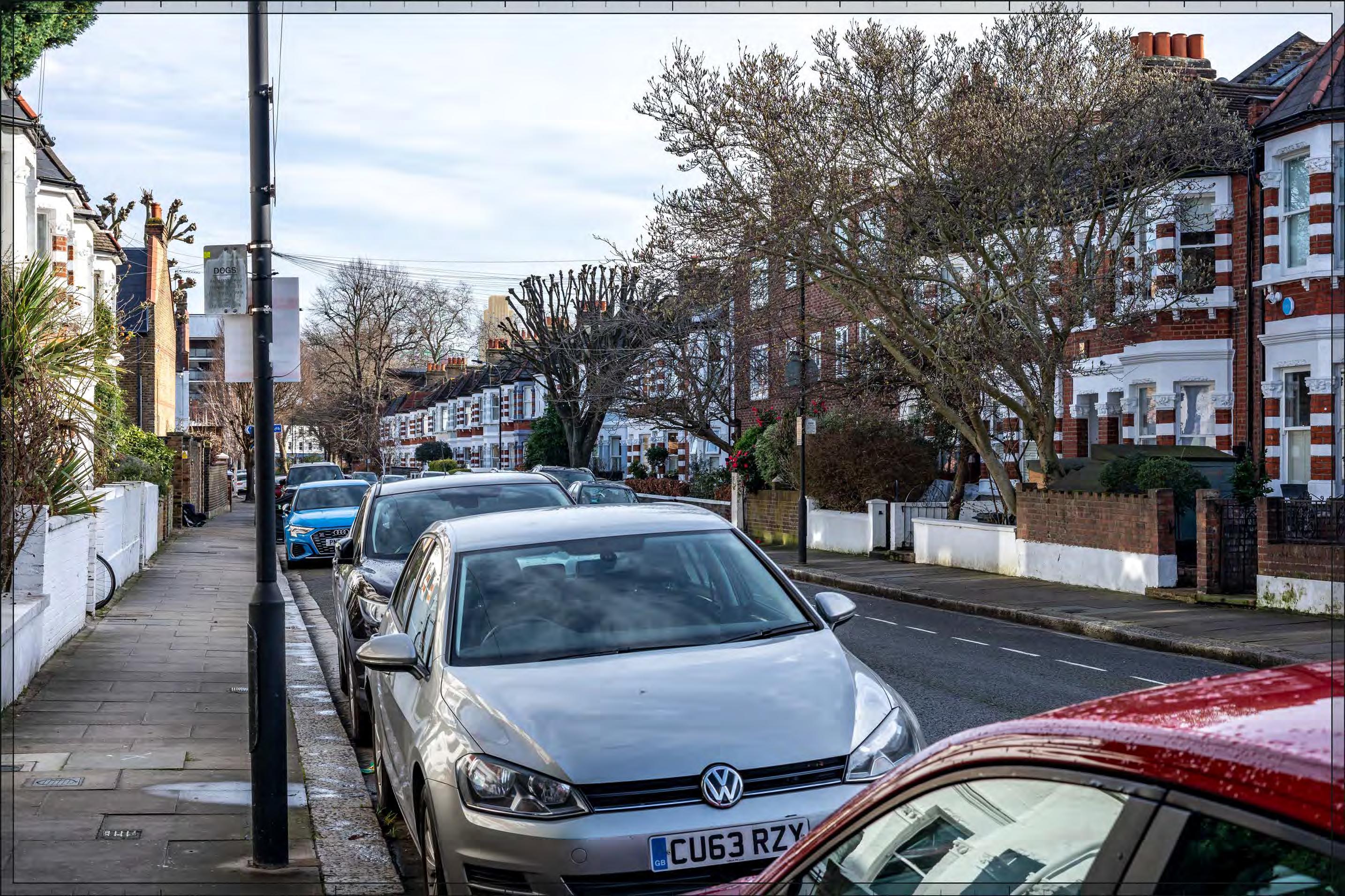
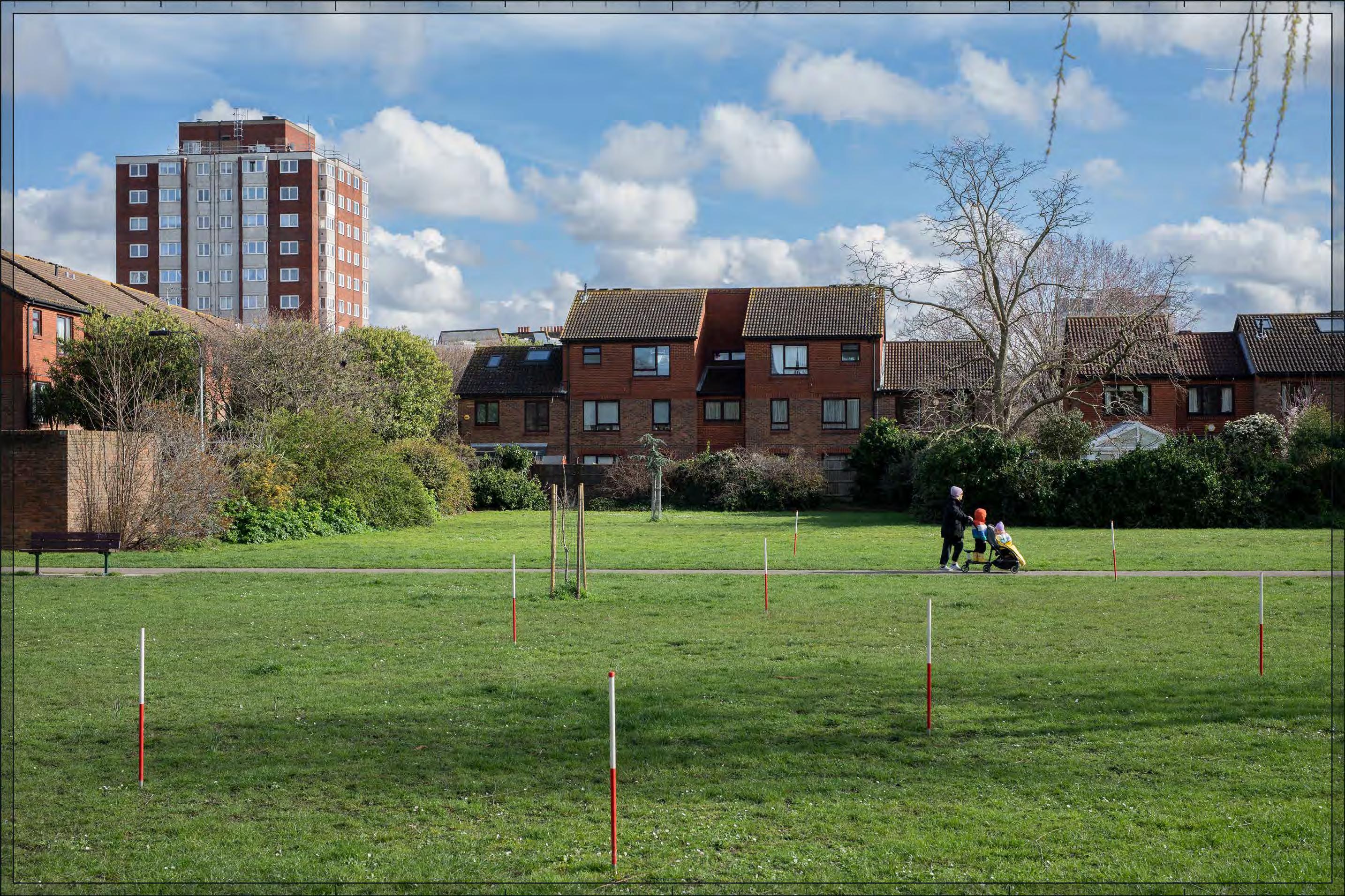
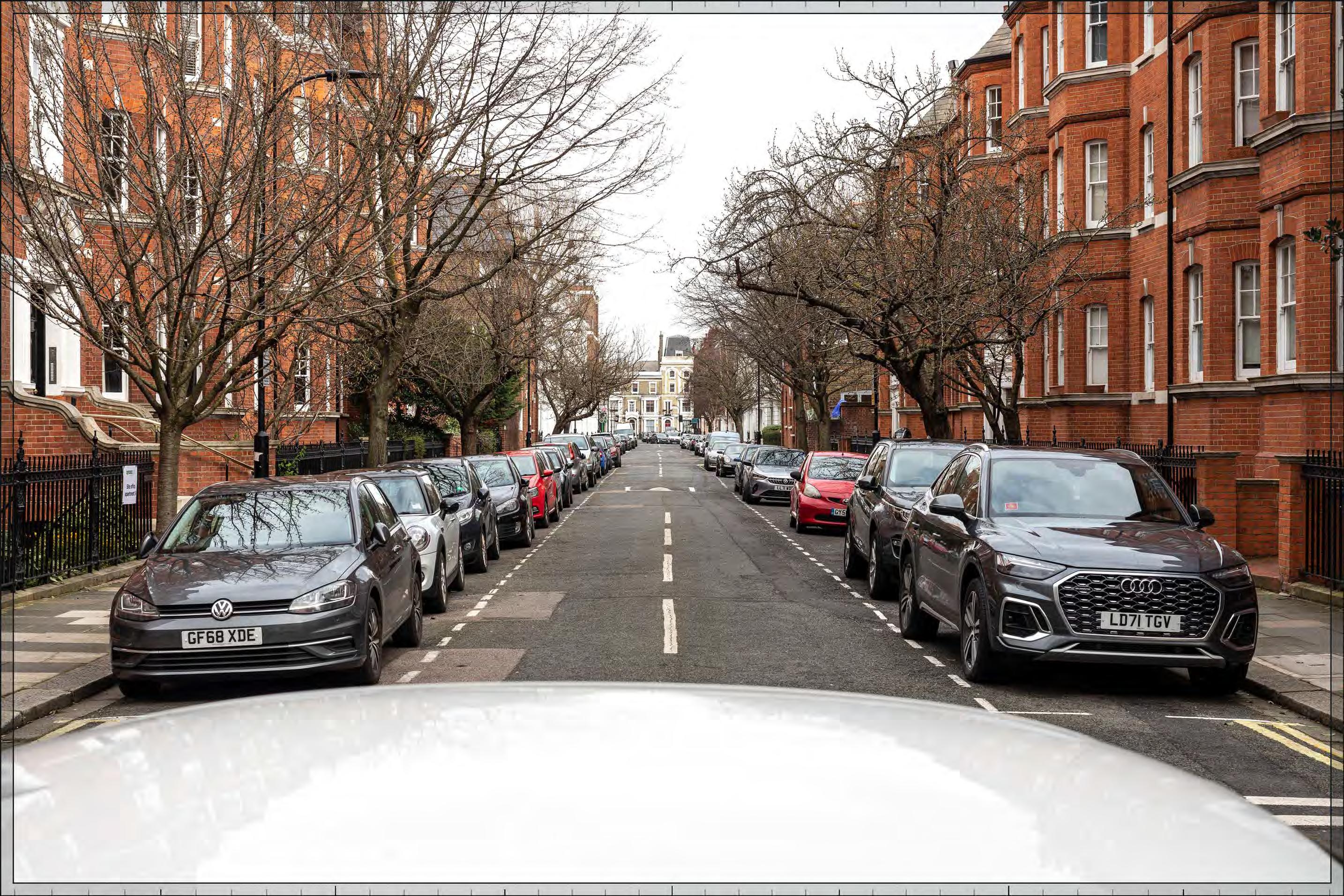
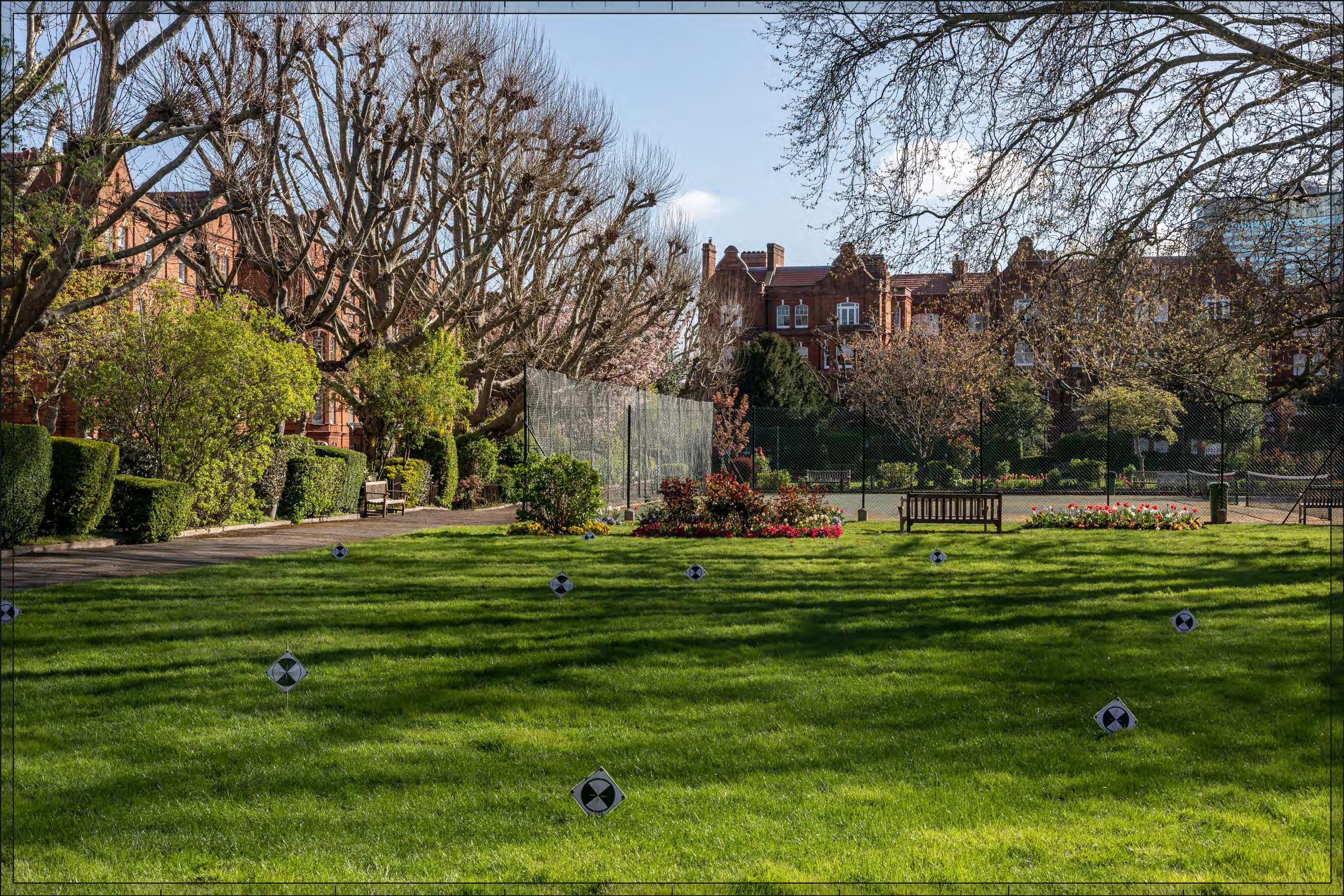
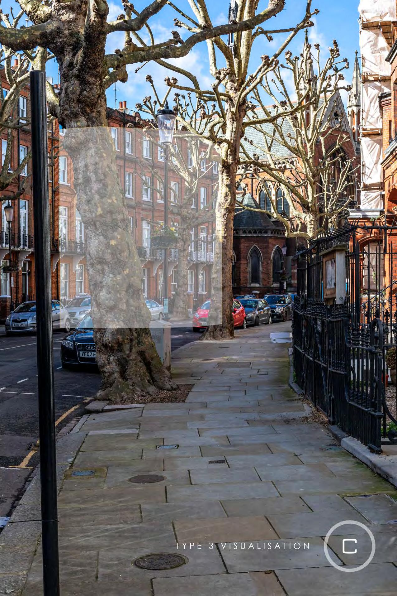
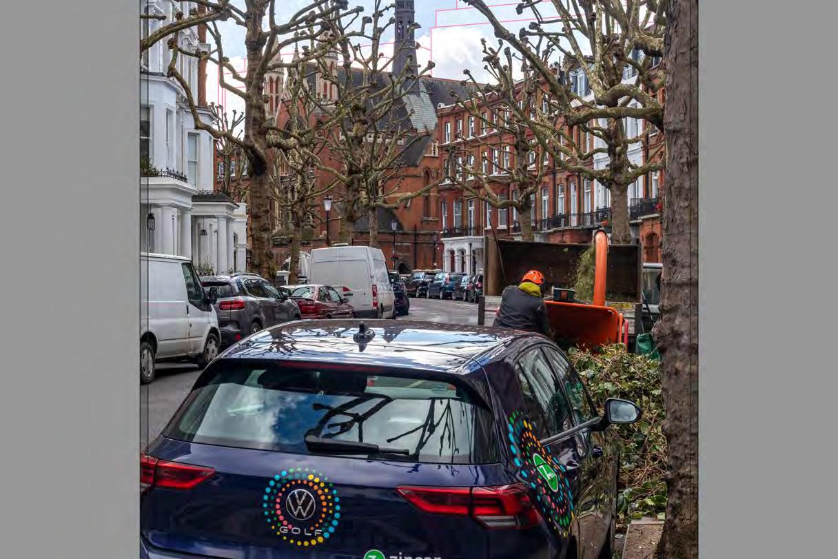
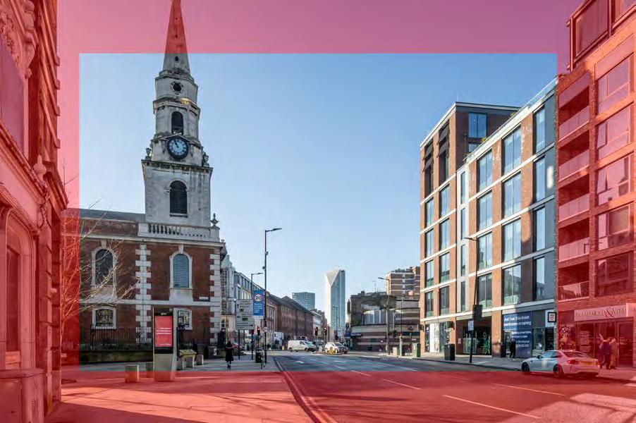
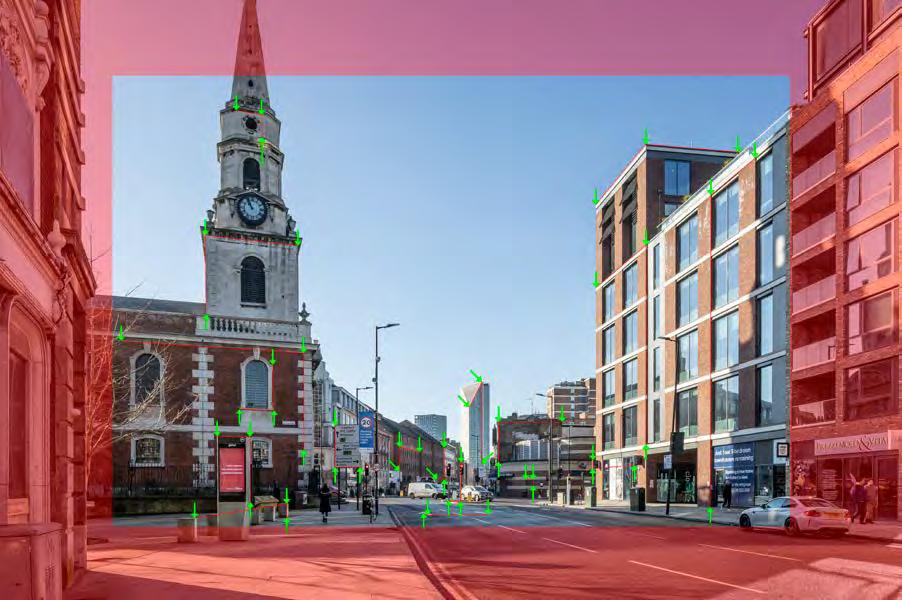
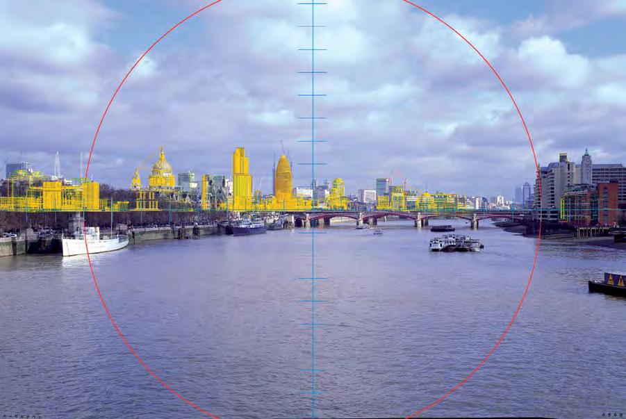
All lenses exhibit a degree of geometric distortion. The most common types are radially symmetrical along the principal axis of the lens, and tend to grow in size towards the perimeter of the image. The outer edges of the images are therefore not taken into consideration to reduce inaccuracies. Figure 5 illustrates the ‘safe’ or non-distortive area of an image which is marked by a red overlay
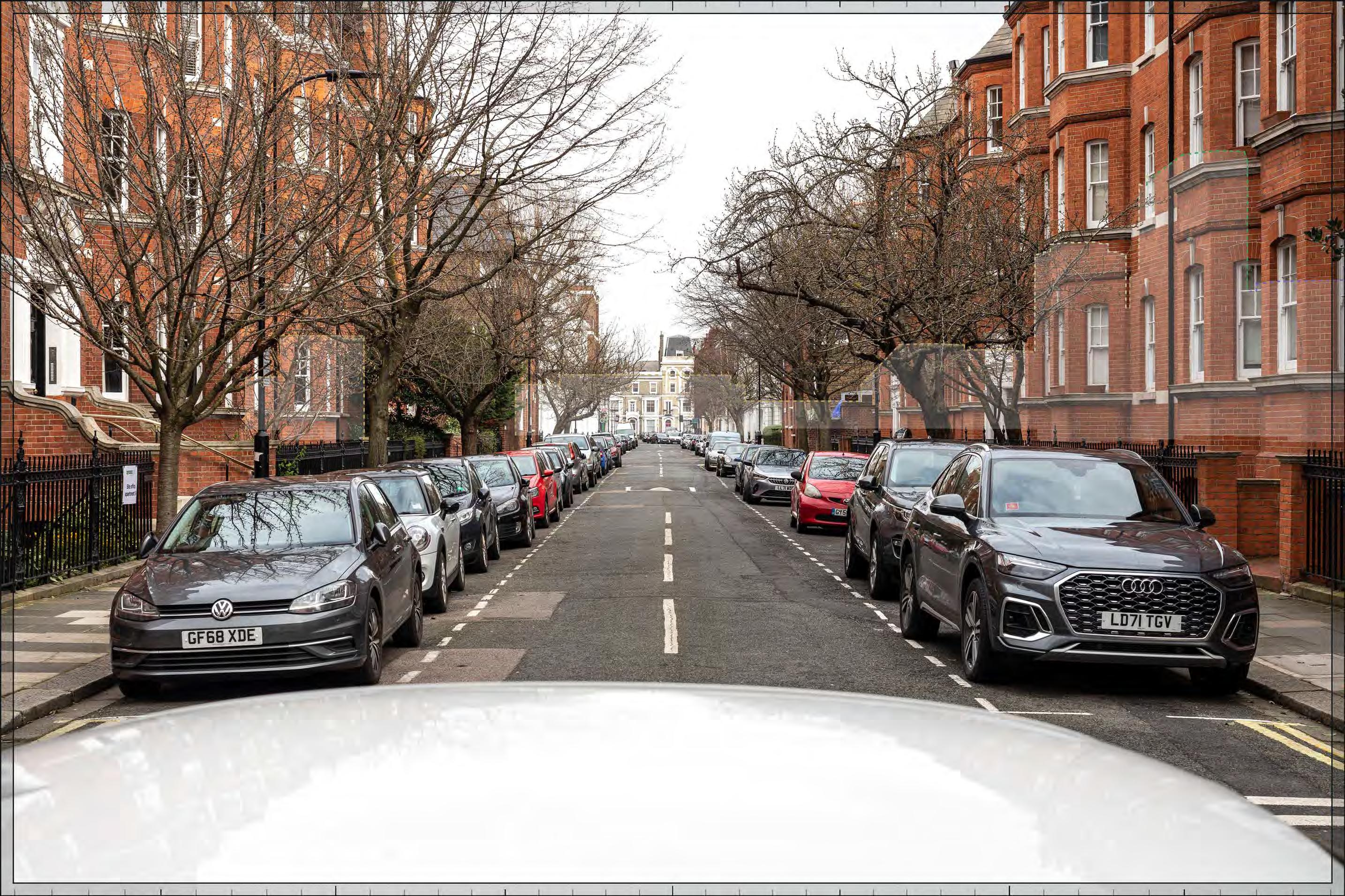
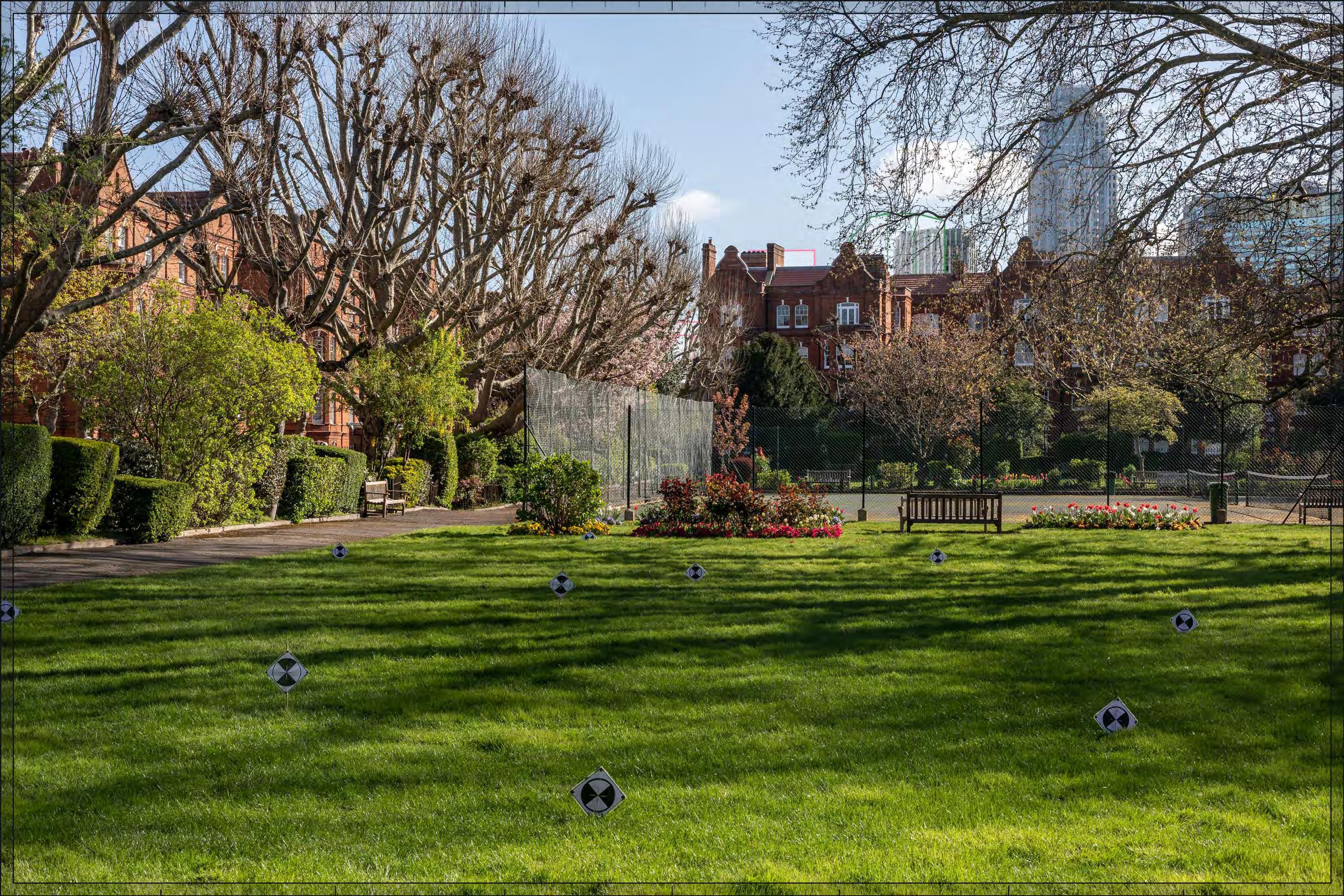
The adjusted or corrected digital image, known as the ‘background plate’, is then saved ready for the camera matching process (see Sections H.6 and H.7). In preparation for the survey (see Section H.3.2) Cityscape indicates on each background plate the safe area and priority survey points, such as corners of buildings, retained elements and party walls for survey (see Figure H.6).
Figure H.6: Background plate highlighting critical survey points in green and secondary survey strings in red
Figure H.5: Area of interest to be surveyed
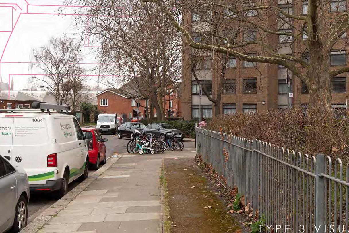
2.3 Type 4 visualisations
2.3.1
Type 4 visualisation
Unless otherwise specified visualisations are completed to TGN 06/197 Type 4 Photomontage / Photowire (survey scale verifiable) standards.
2.3.2
Survey
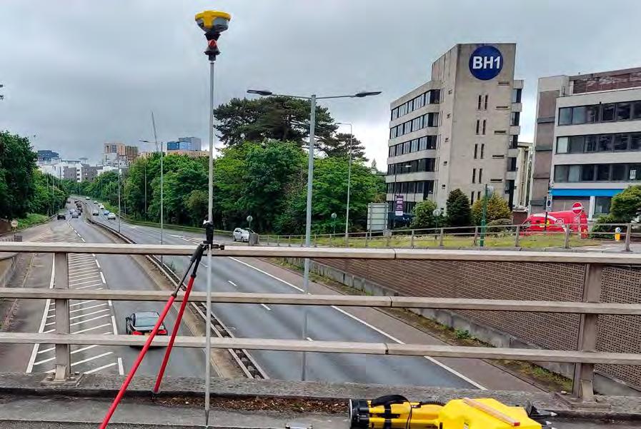
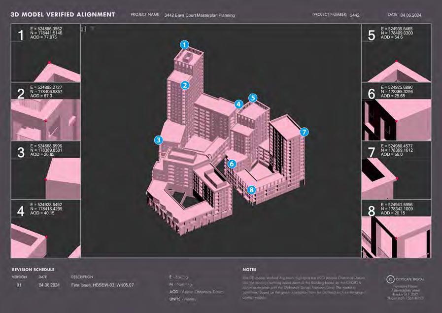
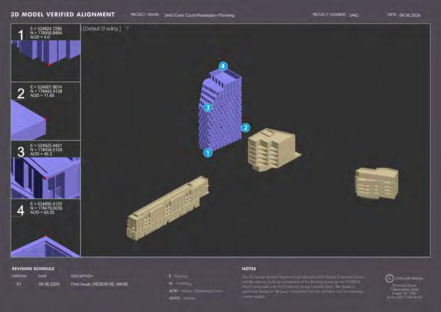
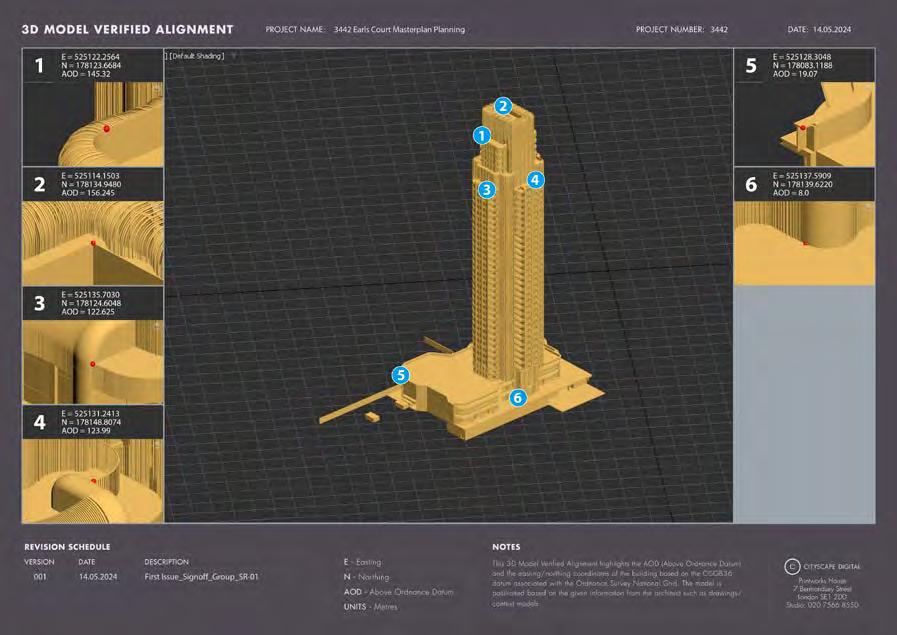
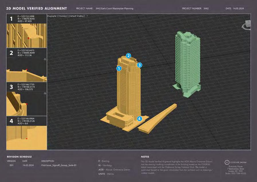
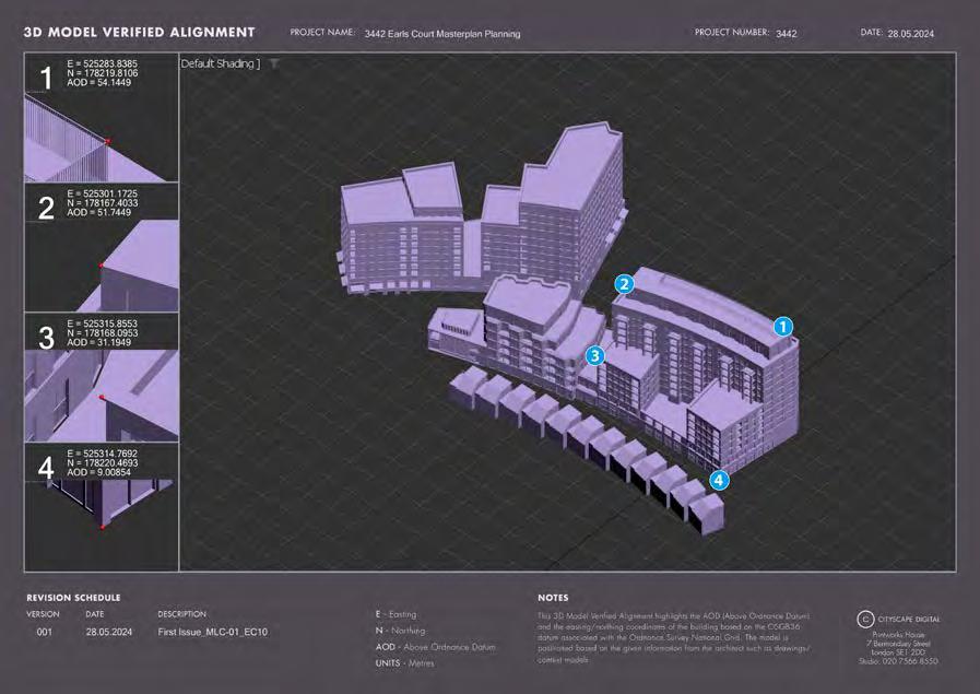
An independent surveyor is contracted to undertake the survey of (i) each viewpoint as marked on the ground beneath the entrance pupil of the lens at the time the photograph is taken (and recorded by way of digital photograph (see Section H.1 above) and (ii) all the required points on buildings, hard landscape features or immobile permanent objects within the safe zone. The survey is coordinated onto the Ordnance Survey National Grid (OSGB36) by using GNSS (global navigation satellite system such as GPS8) equipment (see, for example, Figure H.7) and processing software. The Ordnance Survey National Grid (OSGB36) is chosen as it is the most widely used and because it also allows the captured data to be incorporated into other available digital products (such as Ordnance Survey maps). The height datum used is Ordnance Survey Newlyn Datum and is also derived using the GNSS.
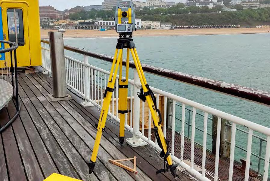
Improvements to the real-time position of GNSS data is achieved by RTK (real time kinematic) compensation, which utilises a comparison between known base stations positions and their current position fix to produce correction data to the measurements. The required points on each building are surveyed using conventional survey techniques utilising an electronic theodolite and reflectorless laser technology (shown in Figure H.8). In certain circumstances, a viewpoint may need to be surveyed using conventional survey techniques as opposed to RTK, if, for example, the viewpoint is in a position where GNSS information cannot be received.
2.3.3 False origin
3D modelling programs, unlike CAD/BIM programs, have inherent inaccuracies the further an object is away from the origin. Cityscape decide on and record a local, ‘false origin’ that is used to move the model closer to the origin. This alleviates the inaccuracies. The 3D model of the proposed development, consented scheme models, and survey data are all moved uniformly to this new false origin. When performing positioning checks (see Section H.5.2) the offset between false origin and OS are added back to the coordinates.
7 ‘TGN 06/19 Visual Representation of development proposals.’ Available at: https://landscapewpstorage01.blob.core.windows.net/www-landscapeinstitute-org/2019/09/ LI_TGN-06-19_Visual_Representation.pdf
Figure H.8: Field survey being carried out, total station
Figure H.7: Field survey being carried out, GNSS receiver
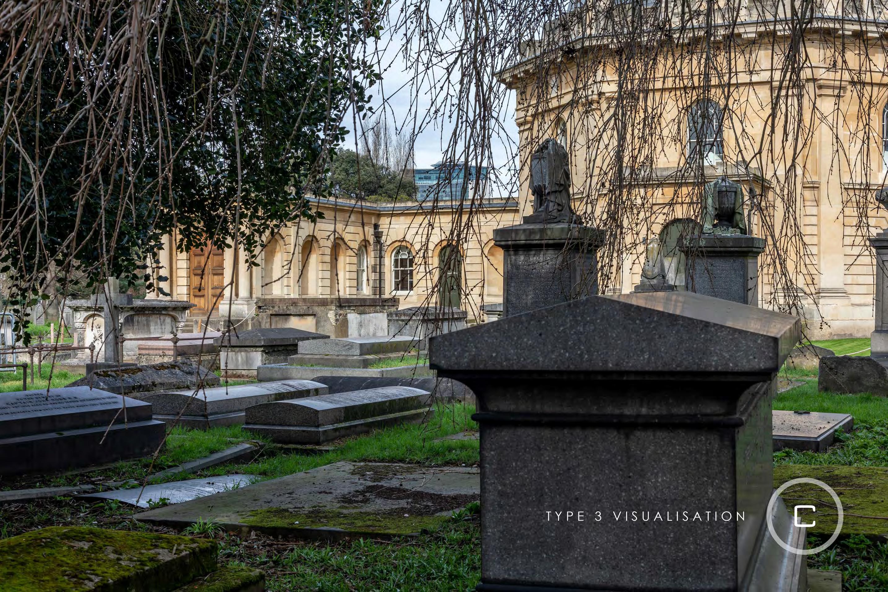
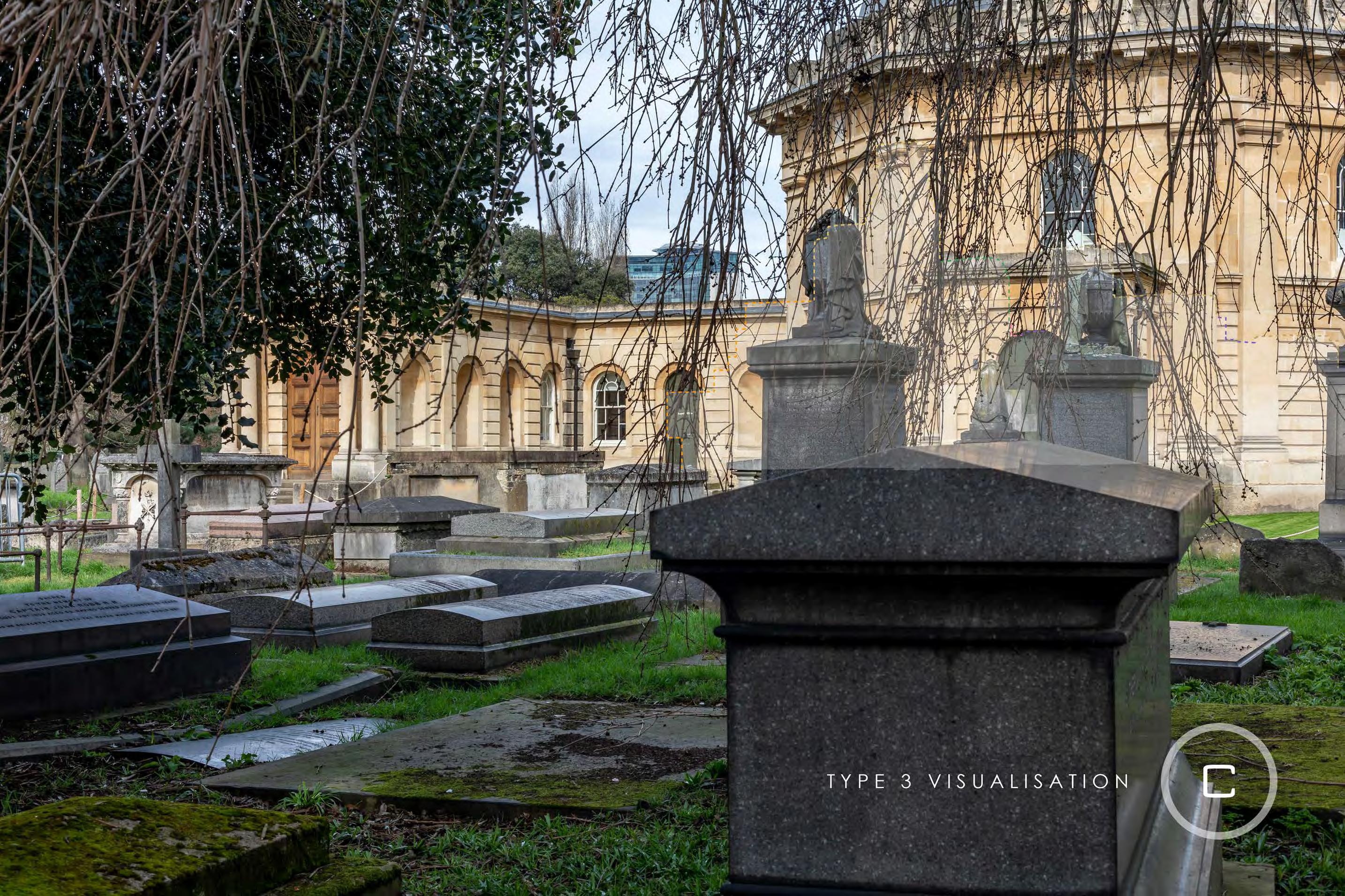
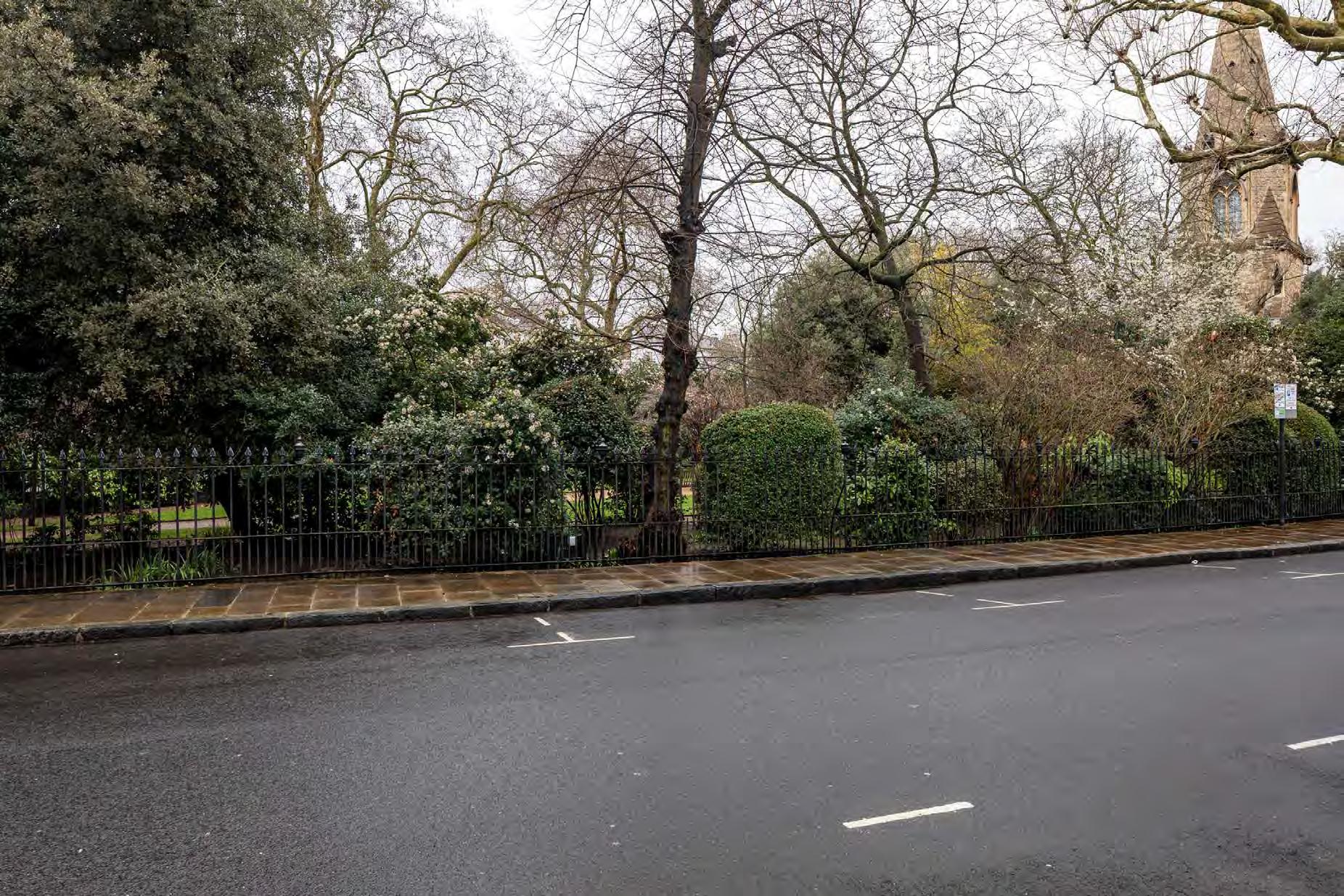
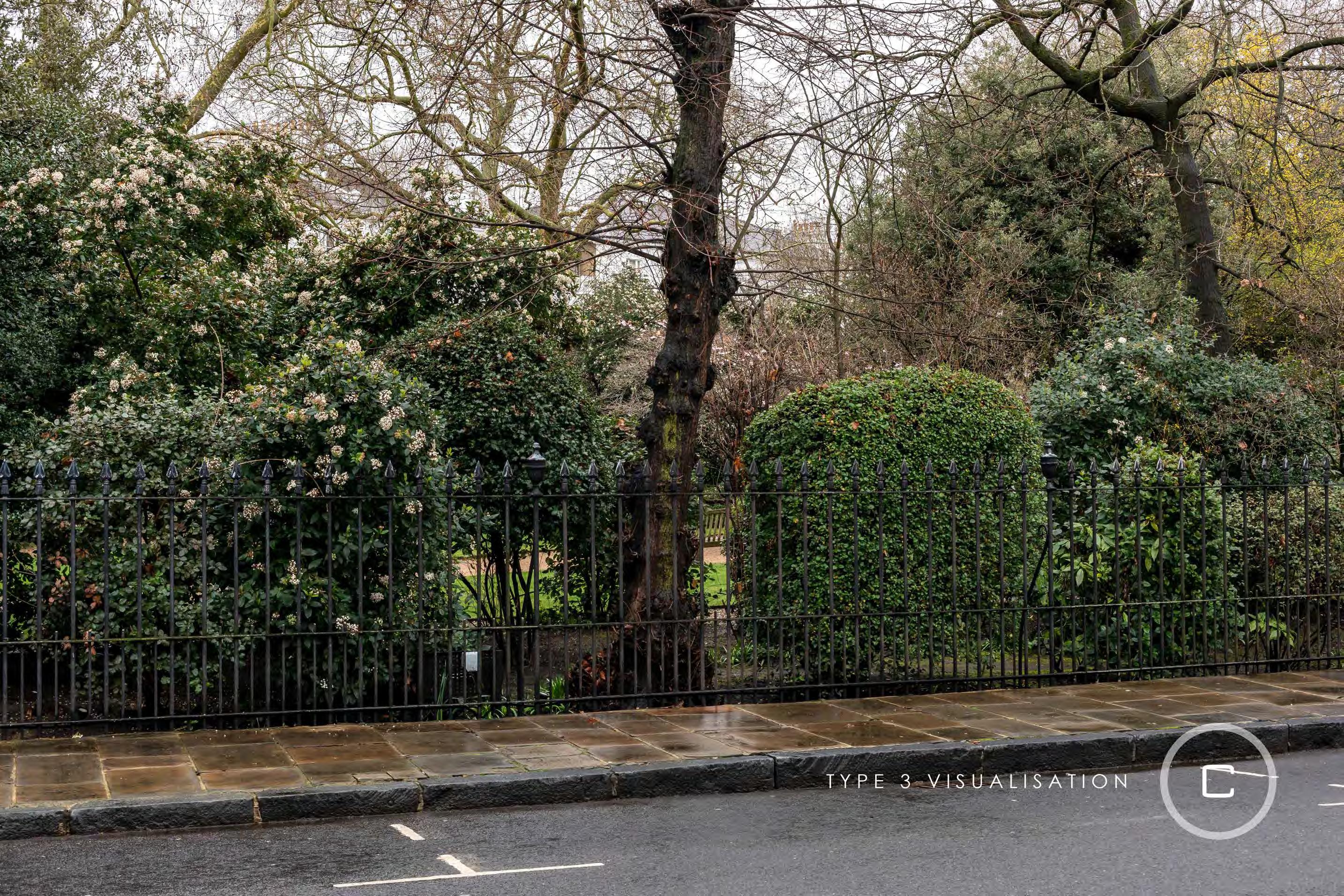
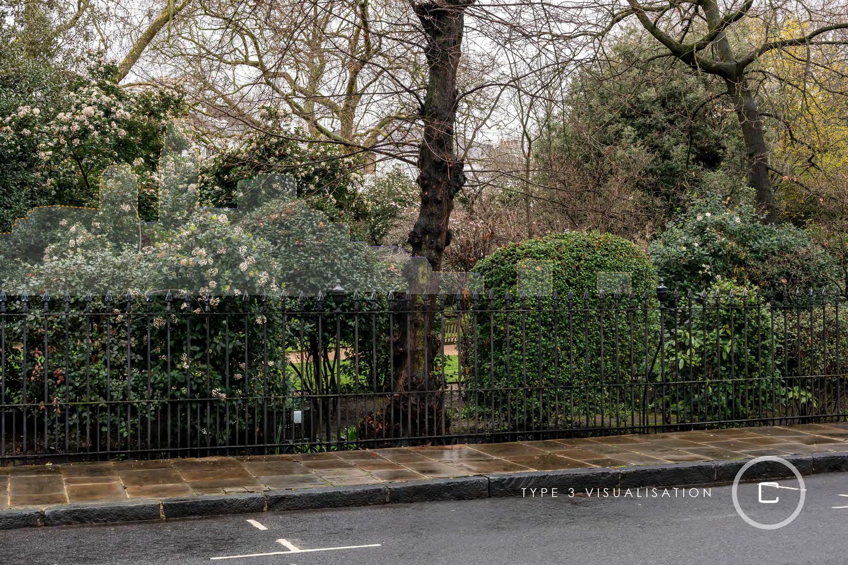
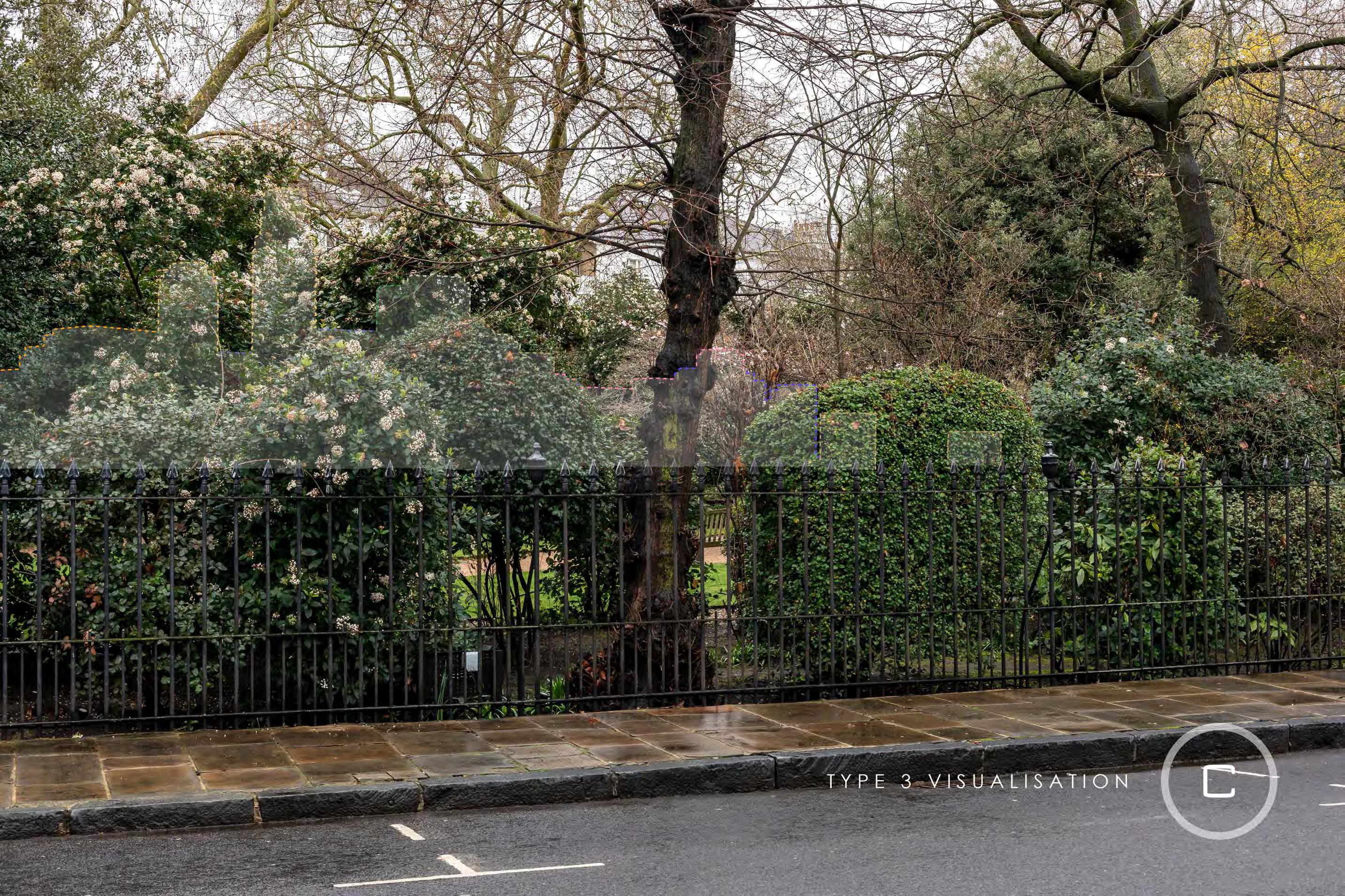
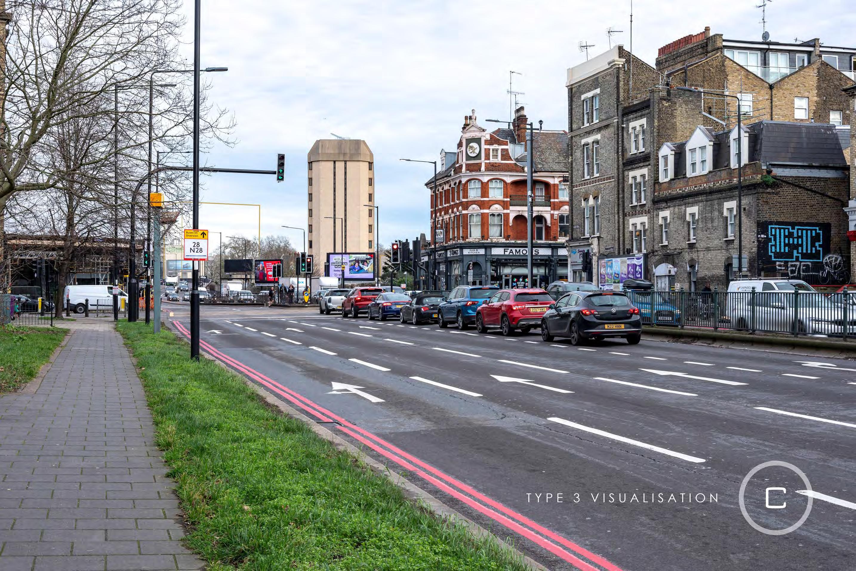
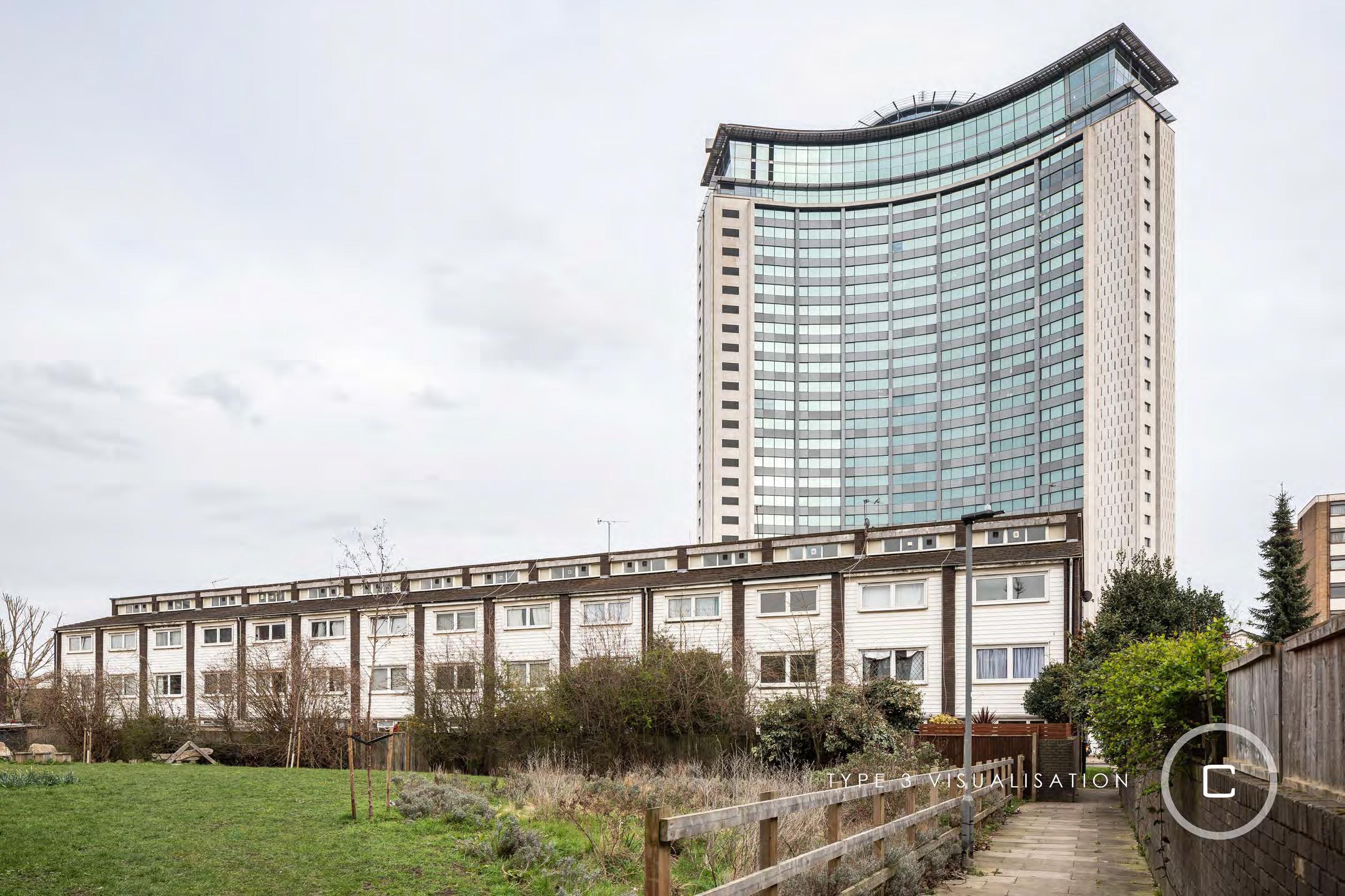
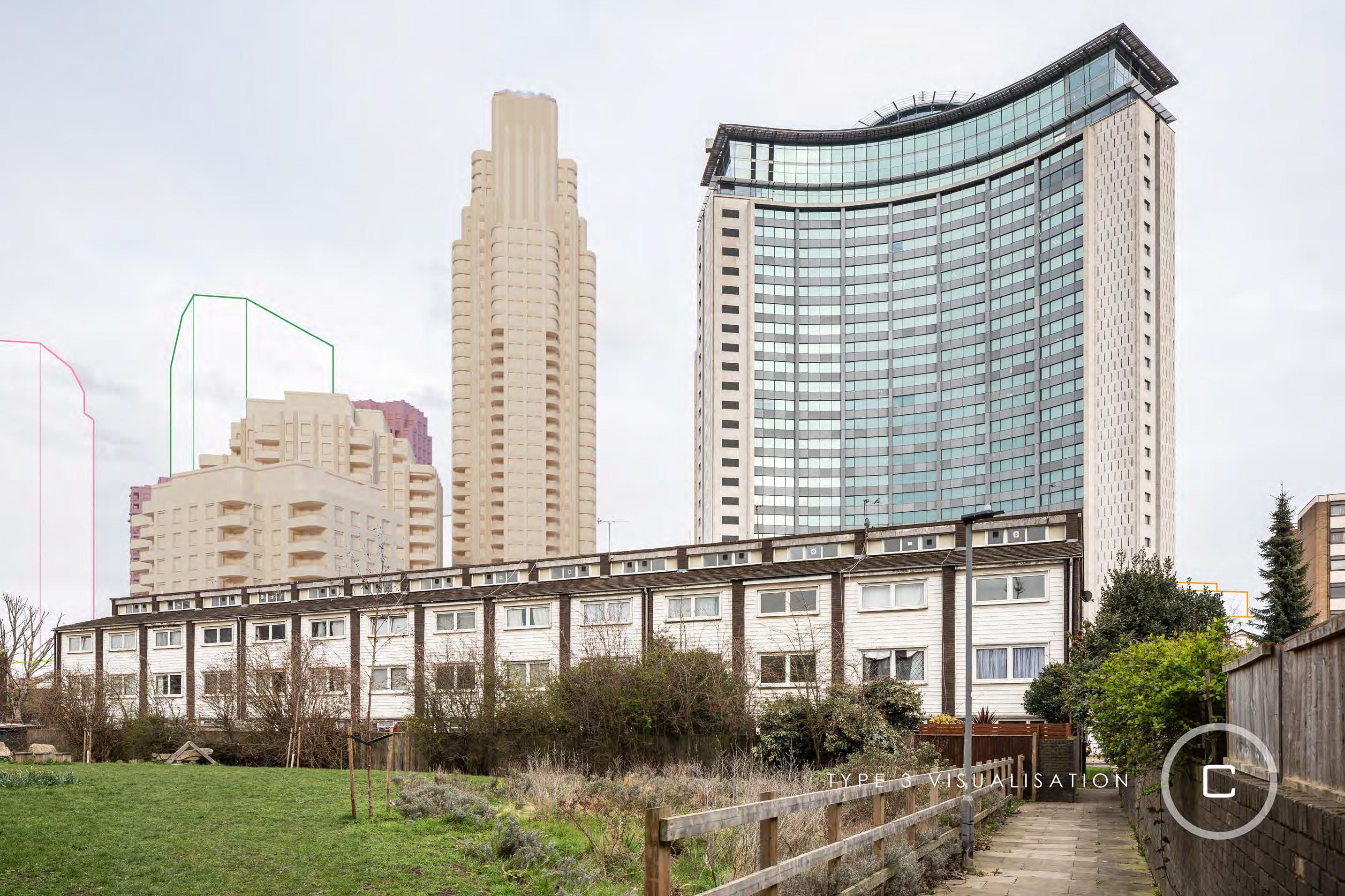
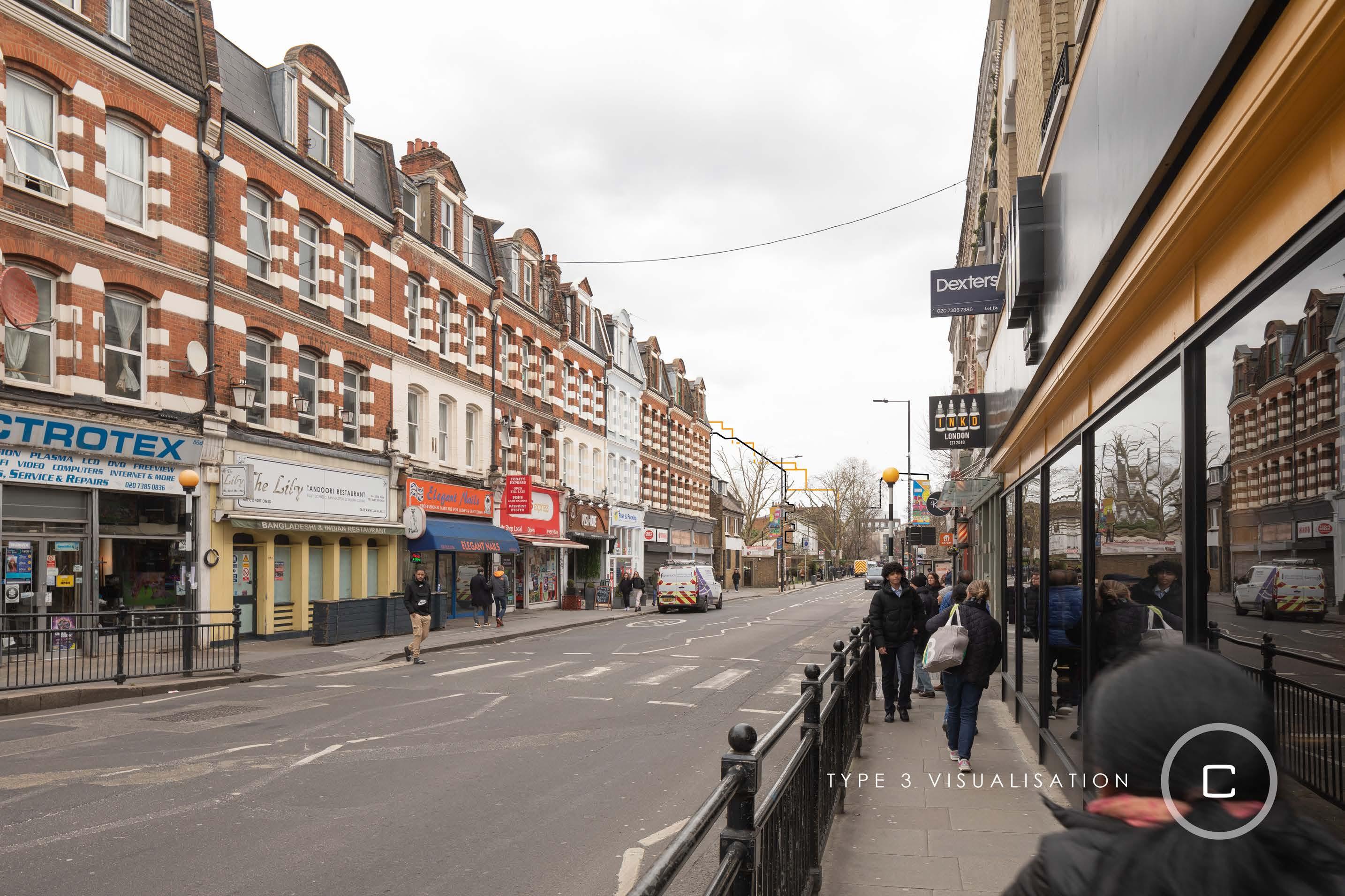
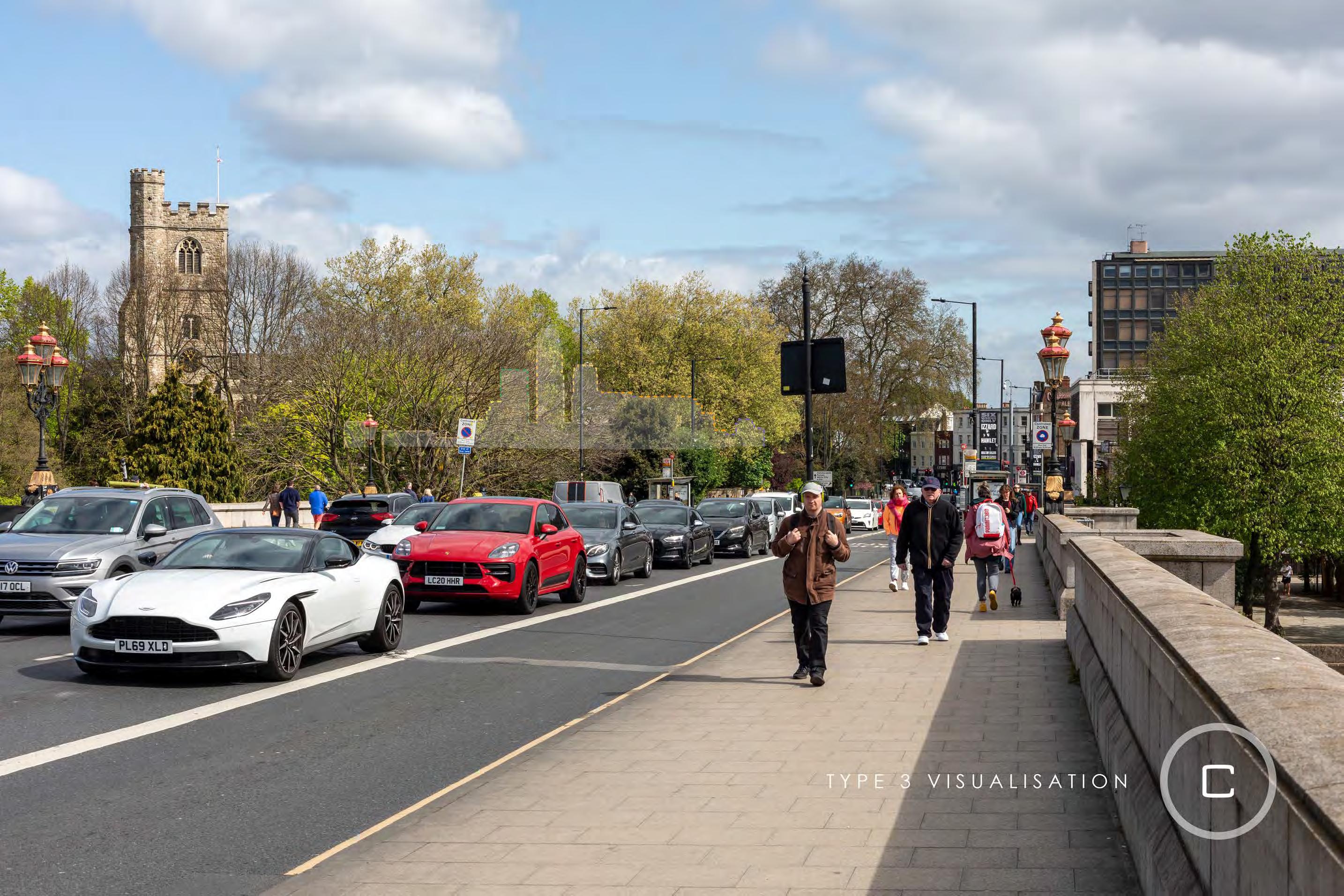
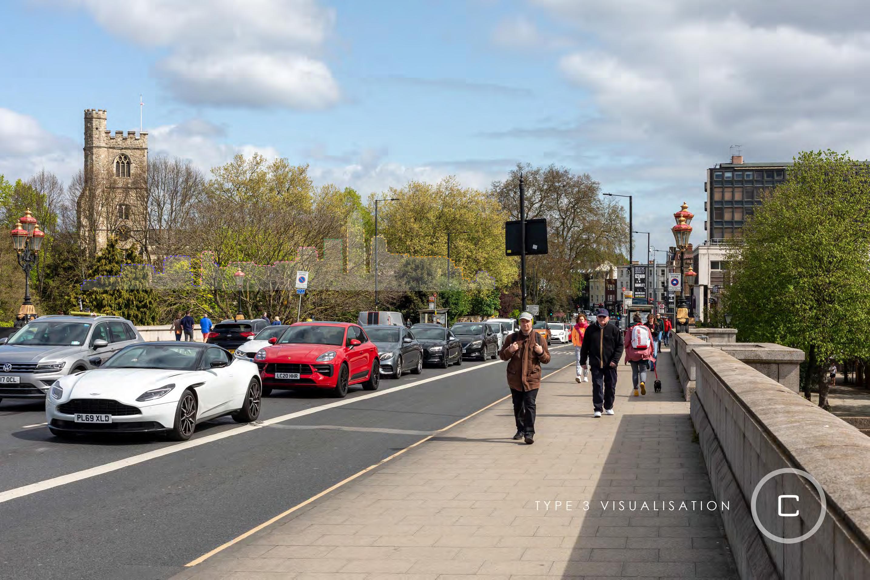
2.4 Type 3 visualisations
2.4.1 Type 3 visualisation
These visualisations are as described in TGN 06/199 Type 3 Photomontage Photowire (not survey / scale verifiable) standards. In contrast to Type 4, Type 3 visualisations rely on good quality data for camera matching, but are not relying on surveys as described in Section H.3.2. Data sources such as GPS, OS Maps, 3D City models, geo-referenced aerial photography, LiDAR or 3D models can be used.
The individual data source used is declared in an accompanying table. The possible angular shift of a 1m lateral displacement of the camera against its actual coordinate depends on the distance of the object from the camera10:
Distance from cameraApparent shift
10m
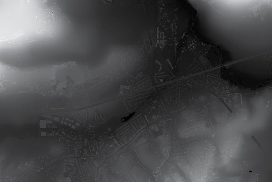
Cityscape also create 3D DSM (Digital Surface Model) models from publicly available data sources, such as Defra LiDAR scans from the Defra Data Services Platform. We always choose the newest data available at the highest possible resolution, typically at 1m resolution. The data is processed to coordinate onto Ordnance Survey National Grid (OSGB36), and converted to a Square Grid DSM. The square grid is then optimised into a TIN (Triangulated Irregular Network). The optimisation has been validated to produce no loss in usable information of the geometric mesh. This process follows the guidelines set out in ‘Guidance – Visual representation of wind farms – Feb 2017’11
Digital Surface Model (DSM) source data is typically the Defra LiDAR Composite DSM, 2020, resolution 1m.
9 ‘TGN 06/19 Visual Representation of development proposals.’
Available at: https://landscapewpstorage01.blob.core.windows.net/www-landscapeinstitute-org/2019/09/ LI_TGN-06-19_Visual_Representation.pdf
(Accessed: March 2022).pp.11, Table2, pp 19-20.
10 ‘TGN 06/19 Visual Representation of development proposals.’
Available at: https://landscapewpstorage01.blob.core.windows.net/www-landscapeinstitute-org/2019/09/ LI_TGN-06-19_Visual_Representation.pdf
(Accessed: March 2022).pp 56-57
11 ‘Guidance – Visual representation of wind farms – Feb 2017’
Available at: https://www.nature.scot/sites/default/files/2019-09/Guidance%20-%20Visual%20 representation%20of%20wind%20farms%20-%20Feb%202017.pdf
(Accessed at March 2022). pp 8-9
2.4.2 False origin
3D modelling programs, unlike CAD/BIM programs, have inherent inaccuracies the further an object is away from the origin. Cityscape decide on and record a local, ‘false origin’ that is used to move the model closer to the origin. This alleviates the inaccuracies. The 3D model of the proposed development, consented scheme models, and survey data are all moved uniformly to this new false origin. When performing positioning checks (see Section H.5.2) the offset between false origin and OS are added back to the coordinates.
2.5 Model positioning
Applies to Type 3 and Type 4 visualisation.
2.5.1
Model source
A wireframe 3D model of the proposed scheme if not provided is created by Cityscape from plans and elevations provided by the architects and from survey information of the ground levels on site and various other points on and around the site, such as the edge of adjacent roads and pavements etc. provided by the surveyor.
2.5.2
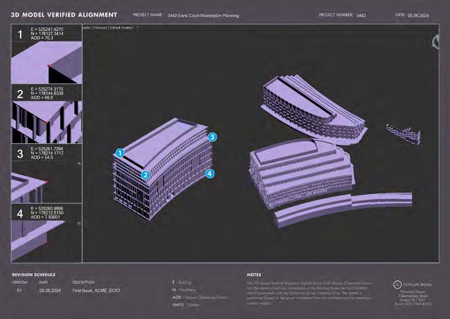
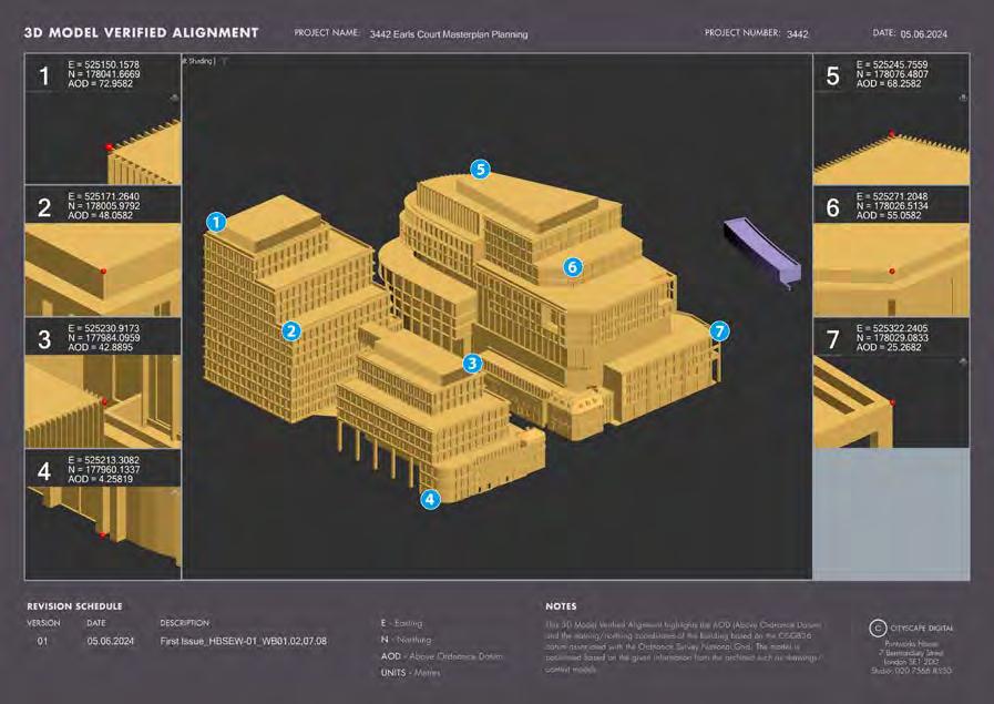
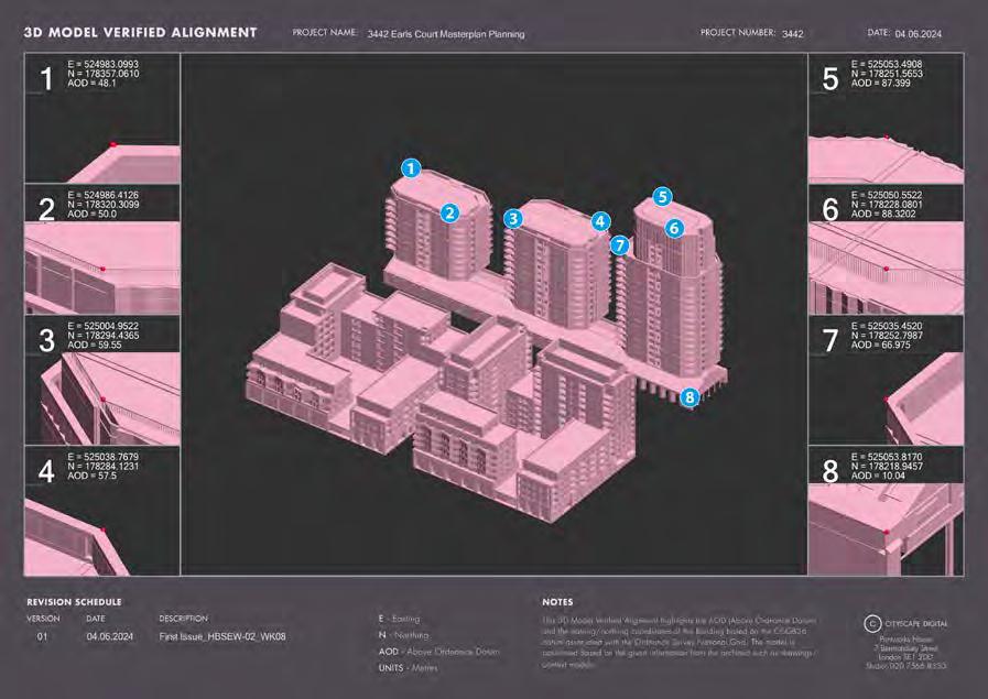
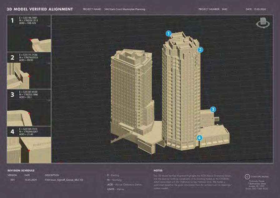
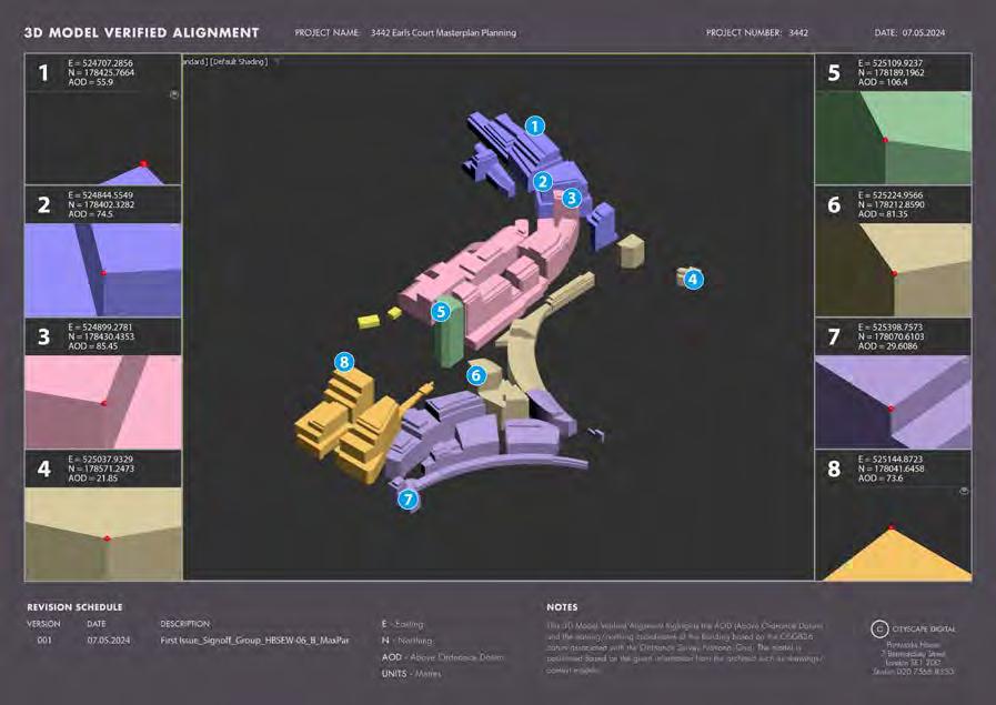
Proposed model position check
The architect supplies a 3D model in OS coordinates that can be used ‘as is’ for position checks as described below (utilising the false origin as described in Section H.3.3). Alternatively, a non OS located model can be provided together with a floor plan that is positioned in an OS map. The model can then be positioned by way of setting it on the floor plan. Heights are either preserved from the original model if supplied in AOD, or taken from supplied elevations.
Once the model is positioned, confirmation of height and Easting/ Northing Coordinates is requested from the architect.
At least two clear reference points are agreed and used to confirm the placement of the model
Figure H.11: 1m resolution LiDAR GeoTIFF
Figure H.12: Resulting 3D TIN mesh
Figure H.13.1: Proposed model position check
Figure H.13.2: Proposed model position check
Figure H.13.3: Proposed model position check
2.5 Model positioning cont.
Figure H.13.4: Proposed model position check
Figure H.13.5: Proposed model position check
Figure H.13.6: Proposed model position check
Figure H.13.7: Proposed model position check
Figure H.13.8: Proposed model position check
Figure H.13.9: Proposed model position check
Figure H.13.10: Proposed model position check
Figure H.13.11: Proposed model position check
2.6 Camera matching – Type 4 visualisations
2.6.1
Cityscape Digital’s database
Cityscape Digital has built up a comprehensive database of survey information on buildings and locations in central London; the database contains both GNSS survey information and information regarding the dimensions and elevations of buildings gathered from architects and other sources.
The outlines of buildings are created by connecting the surveyed points or from the information obtained from architects’ drawings of particular buildings. By way of example of the high level of detail and accuracy, approximately 300 points have been GNSS surveyed on the dome of St. Paul’s.
The database ‘view’ (as shown in Figure H.14) is ‘verified’ as each building is positioned using coordinates acquired from GNSS surveys. In many instances, the various coordinates of a particular building featured in one of the background plates are already held by Cityscape as part of their database of London. In such cases the survey information of buildings and locations provided by the surveyor (see Section H.3.2) is used to cross-check and confirm the accuracy of these buildings. Where such information is not held by Cityscape, it is, where appropriate, used to add detail to Cityscape’s database.
The survey information provided by the surveyor is in all cases used in the verification process of camera matching.
2.6.2
Camera matching process
The following information is required for the camera matching process:
• Specific details of the camera and lens used to take the photograph and therefore the field of view (see Section 1);
• The adjusted or corrected digital image i.e. the ‘background plate’ (see Section H.2);
• The GNSS surveyed viewpoint coordinates (see Section H.3.2);
• The GNSS surveyed coordinates of points within the background plate (see Section H.3.2);
• Selected models from Cityscape’s database (see Section H.6.1);
• The GNSS surveyed coordinates of the site of the proposed scheme (see Section H.3.2);
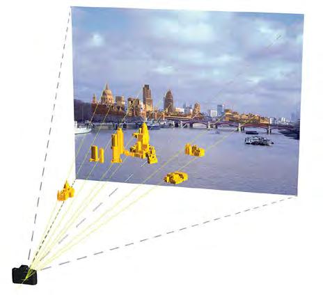
The data is combined in a 3D software package and is then used to situate Cityscape’s virtual camera such that the 3D model aligns exactly over the background plate (as shown in Figures H.15, H.16 and H.17) (i.e. a ‘virtual viewer’ within the 3D model would therefore be standing exactly on the same viewpoint from which the original photograph was taken (Figure H.3). This is the camera matching process.
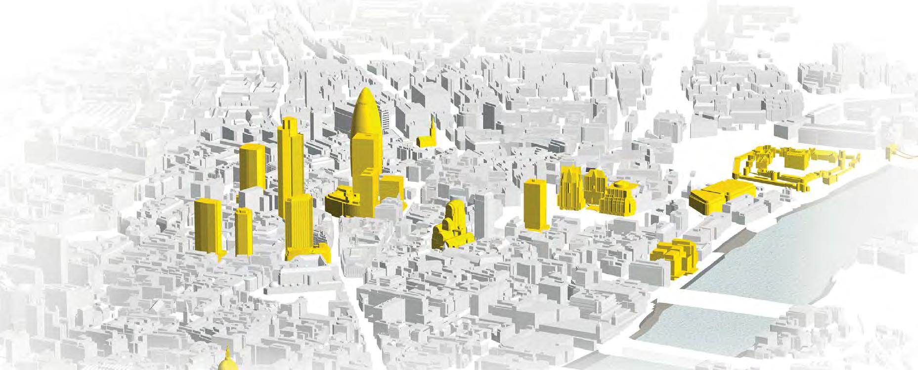
Figure H.14: Selected GPS located models (yellow) from Cityscape’s database, situated on Cityscape’s London digital terrain model
H.15: The background plate matched in the 3D GPS located models
Figure H.16:
Background plate matched to the 3D GPS located models
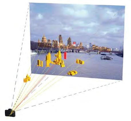
Figure H.17:
The camera matched background plate with an example of a proposed scheme included in red
Figure
2.7 Camera matching – Type 3 visualisations
2.7.1 Cityscape’s context models
Cityscape have purchased available 3D city models of large parts of London and other parts of the UK that are modelled to within 25cm accuracy. Where available this data is used to create camera matches for Type 3 visualisations, or additional data is purchased.
In addition, or where 3D city models are not available, DSM data is used for camera matching (see Section H.4).
2.7.2 Camera matching process
The following information is required for the camera matching process:
• Specific details of the camera and lens used to take the photograph and therefore the field of view (see Section H.1);
• The adjusted or corrected digital image i.e. the ‘background plate’ (see Section H.2);
• 3D city model and/or DSM context model (see Section H.4);
• Selected models from Cityscape’s database (see Section H.6.1);
• A 3D model of the proposed scheme (see Section H.5)
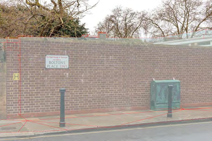
The data is combined in a 3D software package and is then used to situate Cityscape’s virtual camera such that the 3D model/Digital Surface Model (DSM) aligns exactly over the background plate (as shown in Figure H.20) (i.e. a ‘virtual viewer’ within the 3D model would therefore be standing very close to the same viewpoint from which the original photograph was taken (Figure H.3). This is the camera matching process.
Figure H.20: Camera matching: the background plate matched in DSM TIN mesh
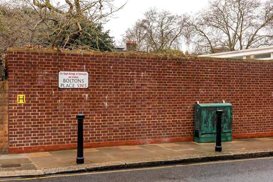
Figure H.18: Background plate: digital photograph, size and bank corrected as described in Section 2
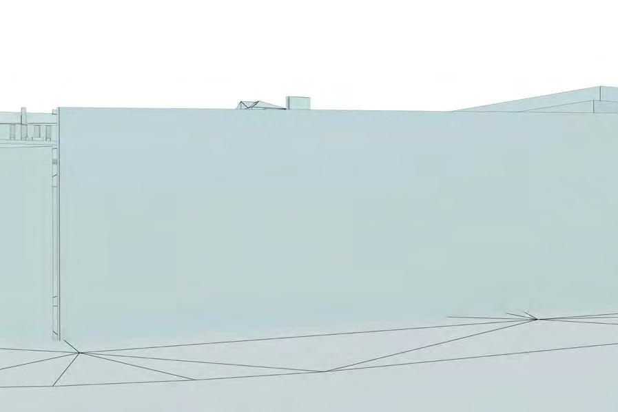
Figure H.19: Render: DSM model render, camera matched
2.8 Rendering
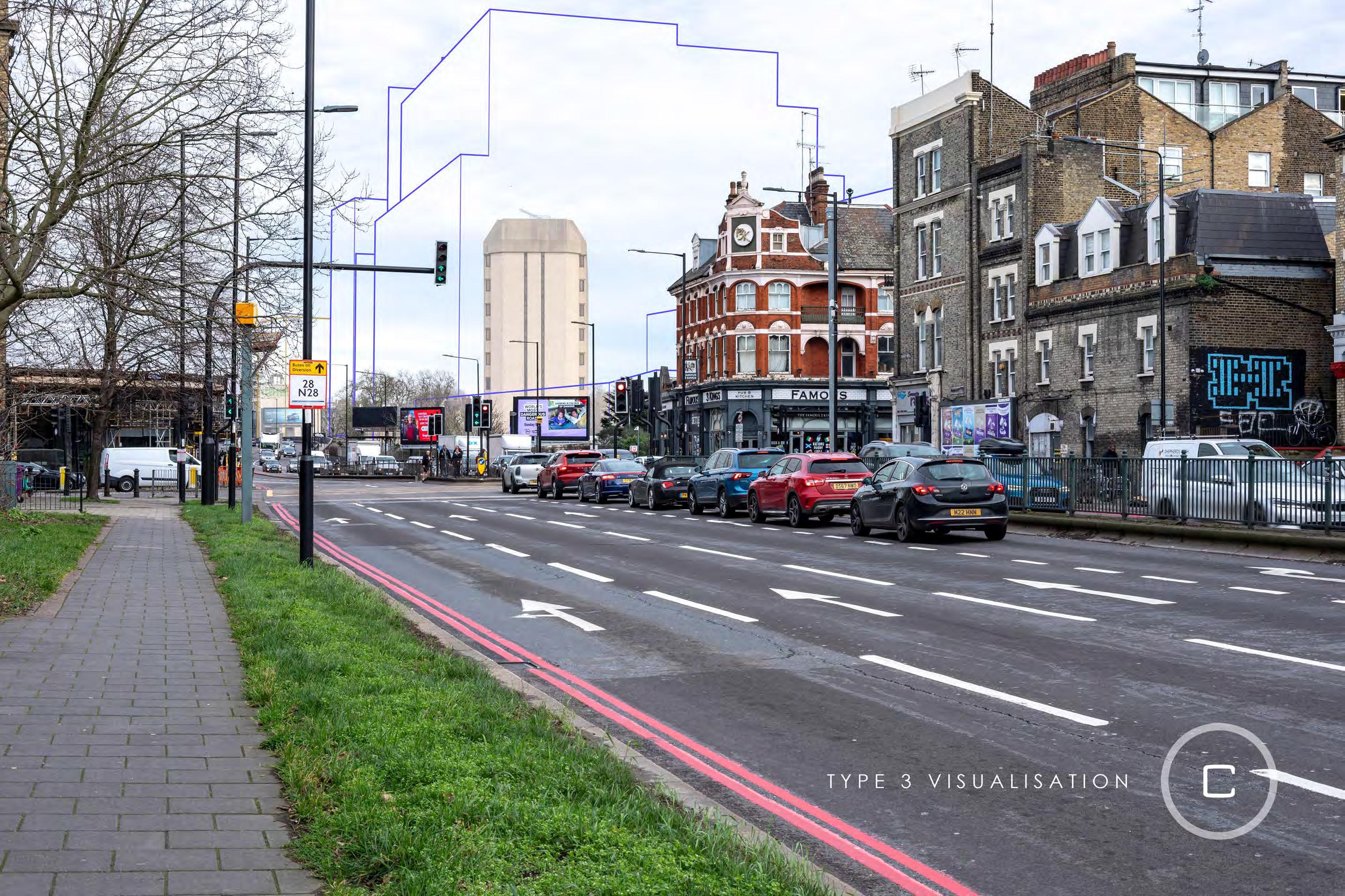
2.8.1 Wireline image (AVR 0/1)
The proposed developments are shown using a constant thickness wireline. The line is generated from a computer rendering of the 3D model and follows an ‘inside stroke’ principle.
Rendering is a technical term referring to the process of creating a two dimensional output image from the 3D model. The ‘inside stroke’ principle is followed so that the outer edge of the line touches the outline of the render from the inside, fairly representing the maximum visibility.
The camera matching process is repeated for each view and a wireline image of the proposal from each viewpoint is then produced. The wireline image enables a quantitative analysis of the impact of the proposed scheme on views.
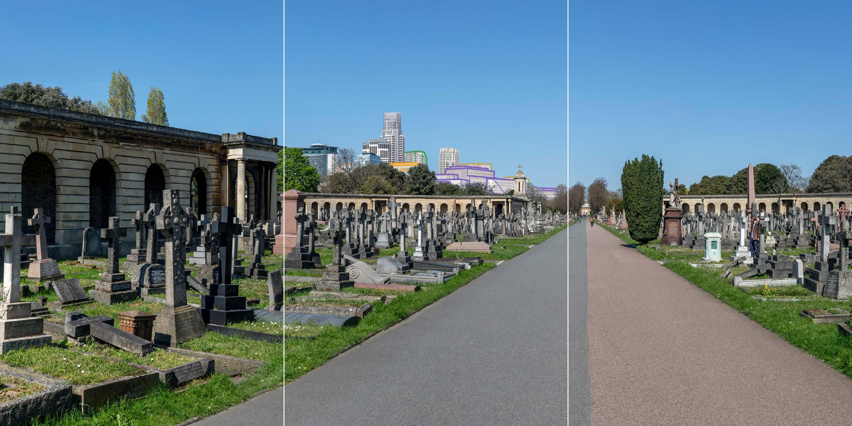
2.8.2 Rendered image (AVR 3)
In order to assist a more qualitative assessment of the proposals, the output image needs to be a photo-realistic reflection of what the proposed scheme would look like once constructed. This is called an AVR3.
2.8.3 Texturing
The process of transforming the wireframe 3D scheme model into one that can be used to create a photorealistic image is called texturing12
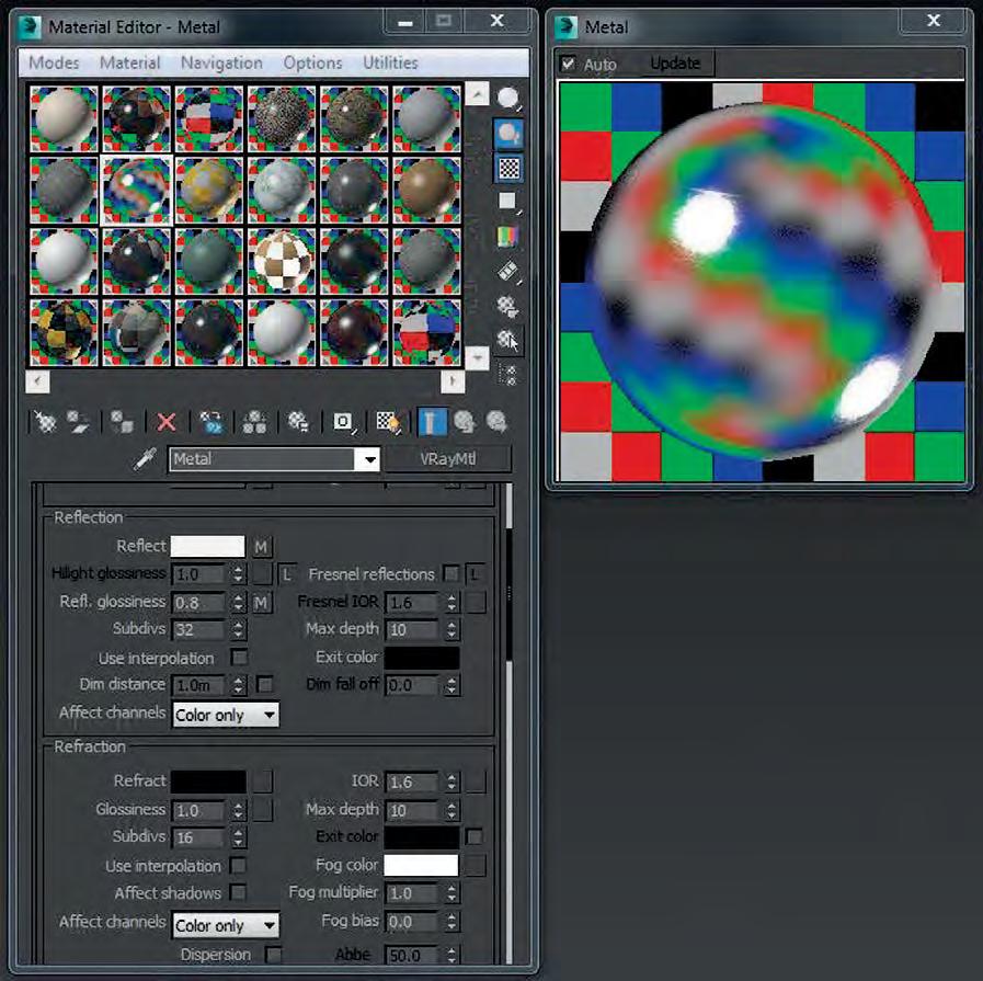
Prior to rendering, Cityscape requires details from the architect regarding the proposed materials (e.g. type of glass, steel, aluminium etc.) to be utilised.
Cityscape also use high resolution photographic imagery of real world material samples, supplied by the client or the manufacturer, to create accurate photorealistic textures for use in all our images. This information is used to produce the appearance and qualities in the image that most closely relates to the real materials to be used (as shown in Figure H.21).
2.8.4
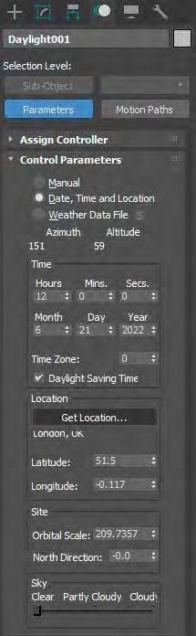
Lighting and sun direction
The next stage is to light the 3D model to match the photographic environment. The date, time of the photograph and the latitude and longitude of the city are input (see Figure H.22) into the unbiased physically accurate render engine. Cityscape selects a ‘sky’ (e.g. clear blue, grey, overcast, varying cloud density, varying weather conditions) from the hundreds of ‘skies’ held within its database to resemble as closely as possible the sky in the background plate.
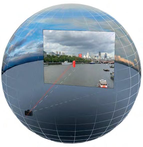
The 3D model of the proposed scheme is placed within the selected sky (see Figure H.23) and using the material properties also entered, the computer calculates the effects of the sky conditions (including the sun) on the appearance of the proposed scheme.
of a proposed scheme h ighlighted in red within the selected sky and rendered onto the background plate
Figure H.22: Screenshot of environment information (time, date and year) entered to locate the sun correctly (see Section 7.
Figure H.21: Screenshot of some materials in the 3D rendering package.
Figure H.23: Example
2.9.1 Post production
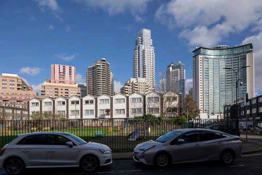
Finally, the rendered image of the scheme model is inserted and positioned against the camera matched background plate.
Once in position, the rendered images are edited using Adobe Photoshop®. Masks are created in Photoshop where the line of sight to the rendered image of the proposed scheme is interrupted by foreground buildings (as shown in Figure H.24).
The result is a verified image or view of the proposed scheme (as shown in Figure H.25).
Figure H.25: A photo-realistic verified image
Figure H.24: Process red area highlights the Photoshop mask that hides the unseen portion of the render