
15th edition Custom Track Service
CUSTOM TRACK SERVICE
Handbook

©1971, 1973, 1974, 1976, 1977, 1979, 1982, 1985, 1987, 1989, 1991, 1993, 1998, 2003 Caterpillar, Inc.
E70B
Edition Fifteen is a comprehensive update to the CTS Handbook. Nearly every wear chart in the book was updated. The General Information section, the Management & Merchandising section and the Management section of the four product types were also updated.
Some of the changes you will notice include:
•Cat Classic was added as a new section following Low Sprocket Machines.
•Nearly all wear charts were updated to some extent.
• The rounding was removed from all measurements for the Ultrasonic Wear Indicator.
• The carrier roller wear limits were increased for use with Heavy Duty, Rotating Bushing and Extended Wear Life Track.
• Track roller wear charts for elevated sprocket machines now extend to the point at which the wear surface meets the retainer bolt holes.
• Greater and Lesser Allowable wear columns were combined into one for large excavators.
•The machine layout is now similar to the PSK, starting with small machines and ascending to the large ones.
•The machine models are up-to-date.
•Pipelayer model numbers were added to the applicable section headers.
•The three excavator sections, the 300-Family, 200-Family and E-Family, can be more easily located with the new, individual tabs.
•Undercarriage Codes for use with the CTS computer program were updated and included in the front of each section and below each wear chart.
•The track seal replacement guidelines were updated.


The ultrasonic wear indicator measures component thickness by sending high frequency sound waves through the material to be measured. The elapsed time between sending and receiving the sound waves allows the tool to determine thickness.
This electronic CTS tool has the following key features and benefits:
•Ultrasonic wave emitting probe•Reduces time spent cleaning parts (especially bushings and shoes).
•Eliminates measurement errors due to dirt packing around parts.
•Measures bushings after turning.
•Eliminates errors due to measurement technique differences among inspectors.
•Measures idler center flange wear.
•Memory•Reduces on-site measurement recording.
•Stores inspections for 64 machines.
•Downloads to CTS computer program for automatic percent worn and projected life calculations.
•Uploads previous inspections from CTS computer program to improve speed and quality
•Language capability•English, French, German, Portuguese, Spanish
•Earphone connector•Allows users to hear “Coupled” beeping indicator
•Backlight feature•Allows users to see the display in poor lighting conditions
The variables that determine complete undercarriage system life and wear balance between components can be divided into three major groupings. The first are those which, to a great extent, are controllable. Controllable variables include track tension adjustment (controlled by user operating and/or maintenance personnel), shoe width (controlled by user operating and purchasing personnel) and on some models, alignment (controlled by user and/or dealer service personnel).
The second major group, non-controllable variables, discussed later in this major section include those life determining factors which are “givens.” They come with the job. They are 100 percent determined by the underfoot conditions and include impact, abrasiveness, packing, moisture, terrain and even application, meaning what the machine is doing.
The final major group is sometimes called partially controllable variables and mainly involve machine operator controllable events such as “habits.”
A thorough knowledge of each of the elements of all these three major groups is essential if the CTS expert is going to be able to not only explain “what has happened,” but also “what could be expected to happen,” especially as any of these variables were to change. Awareness of the relative interplay between these variables on the final wear or structural life of specific components, and even on the system is so important that their discussionhas been placed at the front of this book. To use the rest of the book before understanding these would be counterproductive.
Controllable variables that affect undercarriage life must be separated out for discussion because, in the case of at least the first two, they can have major economic
effect on the operation of undercarriage systems.
Track adjustment can have a very large effect on external bushing life, even to the extent of deciding whether a costly turn will or will not be required to use up the link-roller system. Track tension can also affect track seal integrity. Track adjustment is controllable because the user can change it.
Shoe width, for which a detailed discussion follows, is controllable because the user, with your advice, chooses which shoe to order on his new machine and/or changes to when the machine changes tracks or even jobs. Shoe width as you will learn can effect such widely ranging items as track seal and lubricant integrity to link cracking to roller flange wear to bushing wear rate.
Alignment, the third and least critical controllable variable is discussed here because, particularly on low sprocket machines, it is wrongly blamed as a cause for many symptoms. It is beneficial to know how misalignment does and does not affect wear patterns so you can better identify the real cause, controllable or not. A short discussion on track-excited vibration is also placed in this area even though it is only controllable at machine design time.
Although the method of measuring the reference sag and adjusting the track varies by machine type, the importance for these different machine types does not. As discussed earlier, track over-tightening can drastically affect external bushing life (increasing wear rate as much as three times) and for this reason alone is listed frequently as a “cause” or “accelerator” under the wear and structural problems section for many components. See separate machine sections for complete instructions on track adjustment.
Track shoe width and degree of impact (bumpiness) can affect the wear life of the undercarriage. Since shoe width is a controllable variable, you can improve performance and wear life of the components by choosing the right shoe.
Use the chart on page 54 to help choose the right shoe for a customer based on the following factors.
Choose shoe width to provide adequate flotation, but not more than is needed. The narrowest shoe which provides adequate flotation will prevent the machine from digging in or sinking into underfoot material. Flotation increases proportionally to shoe width.
Additional shoe width does not provide greater penetration or traction and consequently does not increase production assuming adequate flotation.
Additional shoe width increases turning resistance, making the machine harder to handle and decreases productivity.
Increased shoe width improves machine versatility allowing it to change from “hard” to “softer” underfoot conditions without losing flotation. However, increased shoe width accelerates wear and structural damage.
Wider shoes do not improve wear life. The extra wear material provided by wider grousers gives a little extra life. The largest variable affecting shoe wear life is slippage.
Bending stress on the shoe increases proportionately to the distance from the outer edge of the link to the end of the shoe. Cracking, bending and hardware loosening increases as shoe width increases.
Basic Rule of Thumb: Always specify the narrowest shoe possible that will provide adequate flotation and traction without excessive track slippage. See chart on following page.
Wear rates increase on link rail sides, rollers and idler flanges as shoe width increases because of increased load interference. Increased shoe width can also aggravate link cracking.
External bushing wear rate on Sealed and Sealed and Lubricated Track and internal wear rate on Sealed Track increases as shoe width increases in a given underfoot condition. This is due to the increased loads, weight and twisting.
Too wide shoes in high impact or steep terrain can cause pins and bushings to loosen in the link bores. This becomes more evident with high single grouser shoes. Loss of pin and bushing retention prevents successful turn and replacement maintenance.
The following chart shows the effect of track link assembly bending stresses as shoe width increases.
The most costly effect of too wide shoes in high impact conditions and/or steep terrain is the loss of lubricant and seal life resulting in premature dry joints. The wider the shoe, plus the higher the impact, the greater the chance of a pressed track joint “opening up,” allowing loss of lubricant. The loss of lubricant occurs when the bushing slides back and forth along the pin. The clearance between the links created by this “opening up” is called end play. End play is permanent and can only be eliminated by pressing the components tight as at initial assembly or when track press work is performed. For maximum lubricant and seal life the machine should be equipped with the narrowest possible shoes which will provide adequate flotation.
In addition, shoes may have grouser corners cut off to reduce turning resistance and bonding forces without loss of flotation and with little loss of overall wear life.
Users should be aware of all the advantages and effects in productivity and wear/structural life factors when choosing shoe width. If all the symptoms of wide shoes are considered on the user’s machine and the causes are explained then he will be able to choose the shoe width based on a better compromise between productivity and wear life.
Alignment for all Track Type Machines excluding *D9R (SN 7TL1212-up and 8BL1422-up) *D10R (SN 3KR1331-up) and *D11R (SN 9TR202-up and 9XR154-up).
Proper roller frame, idler and sprocket alignment is important to avoid accelerated, unbalanced wear on moving undercarriage components (roller tread and flanges, link rails and rail sides and sprocket segment or rim sides).
As a general rule any wear pattern differences between left and right, inner and outer, or front and rear may be due to
(including diagonal brace)
Toe-In
When viewed from the top, either or both of the roller frames is not parallel to the center line of the tractor.
CAUSE: temporarily (during load only) or permanently bent diagonal brace or roller frame
EFFECT: unbalanced wear when comparing inboard versus outboard roller and idler flanges and rail sides — rollers worsen from rear to front
REMEDY: straighten diagonal braces and repair mounting bearings
Tilt
When viewed from front or rear the roller frame tilts toward or away from tractor.
CAUSE: permanently bent diagonal brace, broken mountings or bearings
EFFECT: unbalanced wear when comparing inboard versus outboard roller, idler, link treads and flanges — unbalance from front to rear on rollers
REMEDY: straighten diagonal brace and/ or repair mountings
improper alignment of one or more parts of the roller frame, idlers or sprocket.
Complete discussion on checking and measuring roller frame alignment plus straightening procedures are discussed in Special Instruction SEHS8146-01 available from Service Publications.
Here is a description of the more common types of alignment problems, their cause, effect, and the steps required to correct the cause:
*Note: These machines have unique Track Roller Frame alignment to increase link and roller life. Thisisfurther detailed in Service Magazine SEPD0469.
Similar to toe-in and toe-out, but roller frame is bent and curves in or out with respect to tractor.
CAUSE: bent roller frame
EFFECT: similar to toe-in and toe-out except rear rollers are not affected
REMEDY: straighten roller frame
When viewed from the front, the roller frame is twisted, with the front end of the roller frame tilted out.
CAUSE: roller frame twisted around a horizontal axis parallel to the tractor
EFFECT: similar to effect of tilt except that rear rollers should not be affected
REMEDY: straighten roller frame
When viewed from top, idler is not parallel to center line of roller frame.
CAUSE: bent idler support box sections or bent idler yoke
EFFECT: wears inner rail sides and idler flanges most — may affect wear on front roller flanges
REMEDY: straighten idler support box sections or yoke
The distance that the tread of the track idler is above the tread of the adjacent track roller.
CAUSE: insufficient or excessive idler height
EFFECT: as track roller tread wear and damage, deterioration or loss of bogie pads occur, and excessive machine vibration may result. Vibration is the result of insufficient idler height. Excessive idler height results in poor dozing control, particularly while performing finish dozing operations.
REMEDY: correct shimming
When viewed from top, idler is parallel to, but moved toward or away with respect to the tractor and roller frame.
CAUSE: improper shimming
EFFECT: wears inner or outer idler flanges and inner rail sides selectively and may affect front roller(s) if severe
REMEDY: correct shimming
When viewed from front, idler tilts out of vertical plane.
CAUSE: bent idler support box frame (inner and/or outer up and/or down with respect to each other)
EFFECT: same as toe-in or toe-out
REMEDY: same as toe-in or toe-out
When viewed from top, sprocket not parallel to center line of roller frame.
CAUSE: sprocket shaft bent forwards or backwards
EFFECT: wears both inner link sides and both sides of segments
REMEDY: straighten or replace sprocket shaft
When viewed from rear, sprocket is leaned or tilted in or out with respect to the roller frame.
CAUSE: sprocket shaft bent up or down
EFFECT: inboard or outboard sprocket sides and rail insides worn selectively, may affect rear roller flanges
REMEDY: straighten sprocket shaft
When viewed from top or rear, sprocket is parallel to but moved in or out with respect to tractor and roller frame.
CAUSE: sprocket not pressed proper distance onto shaft
EFFECT: inboard or outboard sprocket sides and rail insides worn selectively, may affect rear roller flanges
REMEDY: re-position sprocket on shaft
1.The larger and heavier the machine and the more severe impact, the greater likelihood of temporary and permanent alignment problems.
2.Alignment problems of roller frame idler and sprocket will affect all links the same.
3.Alignment problems of roller frame, idler and sprocket will affect rollers unequally from front to rear and from inner to outer flanges and treads.
4.Horizontal straightness of roller frame will not affect track but will affect front and/or rear roller treads compared to center.
5.Snaky track will not cause near the degree of damage as compared to misalignment.
6.Carrier rollers can be used as a more visual indicator of roller frame alignment but are not as reliable as comparing track rollers.
7.If left side of tractor has different misalignment-type wear patterns than right side, the problem is probably due to permanent, rather than temporary, (working loads) causes.
8.Unbalanced loads due to side hill operation will result in front to rear and left side to right side similarly in wear patterns on all parts affected.
9.If misalignment is suspected, it is important to at least measure the misalignment degree, if not completely correct it before installing new undercarriage components.
10.Tight track increases the effect of all types of alignment problems because it increases the loads between the interfering components.
For more complete descriptions and cross reference of specific component wear patterns that may be caused by misalignment, refer to the discussions under each component and model.
Track-excited vibration is the most widely encountered vibration on track-type machines. However, it is not understood by many persons who work with these machines. As the machine moves, each link, as part of an endless rail, makes contact with two curved surfaces — each with a different radius. These are the idler and the track rollers. Contact between the links, idler and rollers results in wearing of the links’ once-straight surface. The contact between the idler and the link creates a worn radius in the center of the link similar to that of the idler.
The track rollers have a similar effect on the ends of the links, which are narrowed to permit them to overlap where they are connected together. Because this overlap isn’t 100 percent, the greatest amount of wear is near the ends of the links, and the size of the worn area has a radius similar to that of the track rollers. As a result of this wear, a scallop pattern is formed on the surface of each track link. (See page 30). This type of link wear can be accelerated by three factors — abrasiveness and moisture content of the soil, machine weight and travel speed and underfoot conditions. Rough underfoot conditions can place higher loads at a given point on a link. It is possible, on rocky or rough terrain, to have a higher load on a link on one side of the machine than on the other side. Although rough terrain can accelerate wear, it is sometimes possible that track-excited vibration will go unnoticed on rough terrain, yet be apparent when the machine is working on a smooth surface.
Along with the depth of scallop, the scallop-roller spacing relationship is what determines how smoothly the machine will travel on the links. If the spacing of the track rollers and scallops are uneven, so that some of the rollers are on the high points of the links while others are over the low points, the machine will move across the scallops smoothly. However, if the spacing is the same, the rollers will rise
and fall in unison with each scallop as they pass over the links, thus creating vibration.
Two factors, machine speed and the depth of the scallops, affect the amount of vibration. The speed of the machine determines the frequency of the vibration while the depth of the scallops controls the amplitude of the vibration. In addition, natural frequencies, which occur in all structures, can respond to the vibration. Because of this response, it is possible for certain parts of a machine, such as the roll-over protection structure, sheet metal components, or, sometimes, the whole machine, to respond to the initial frequency and begin vibrating.
The vibration can be reduced by replacing deteriorated isolation mounts where necessary, replacing any broken or missing fasteners and by generally keeping the machine in good repair. A change in operating speed or technique, or a change of counterweights or attachments may reduce the effect.
Operator complaints of ride arise when a machine is vibrating more than normal. Abnormal vibration is generally caused by an idler that is lower than the track rollers, a machine that is not balanced, or scalloped track links.
Special Instruction entitled “Adjustment of the Position of the Front Idlers and the Balance of the Machine for Improved Ride or Improved Fine Dozing,” REHS0862-02, dated June 01, 2001, covers the following topics:
•Correct Track Installation
•Measuring Grouser Rise Height
•Verify the Installation of the Correct Idlers
•Measuring the Depth of the Link Scallop
•Shim Charts for Idlers
•Measuring the Height of the Front IdlerTread
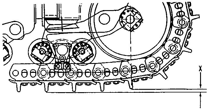
As track roller tread wear and damage, deterioration or loss of bogie pads occur, and excessive machine vibration may result. This vibration is the result of insufficient idler height. Idler height is the distance that the tread of the track idler is above the tread of the adjacent track roller. See Illustration 1 for the area to be measured.

Illustration 1. Idler Height. Under typical operating conditions, wear causes the diameter of the track roller treads to decrease at approximately twice the rate of the track idlers. When the front or rear rollers reach approximately 70 percent wear, the idler height may approach the minimum recommended value. Variations in operating conditions influence the wear rates. Additionally, the installation of new or rebuilt idlers on machines with partially worn track rollers directly affects idler height.
To measure idler height, use the following procedure.
Illustration 2. Measurement points on a hard surface. 1. Move the machine to a hard, level surface. Inspect to make sure all bogie pads are in place. If any pads are missing or unserviceable, they should be replaced.
Chart A
D8L29 mm (1.142 in)17 mm (.670 in)34 mm (1.339 in)10 mm (.394 in)
D8N, D8R15 mm (.591 in)10 mm (.394 in)16 mm (.630 in)10 mm (.394 in)
D9L23 mm (.906 in)11 mm (.433 in)27 mm (1.063 in)11 mm (.433 in)
D9N, D9R24 mm (.945 in)11 mm (.433 in)21 mm (.827 in)11 mm (.433 in)
D1025 mm (.984 in)14 mm (.551 in)32 mm (1.260 in)12 mm (.472 in)
D10N, D10R26 mm (1.024 in)14 mm (.551 in)23 mm (.906 in)12 mm (.472 in)
D11N, D10R32 mm (1.260 in)14 mm (.551 in)23 mm (.906 in)12 mm (.472 in)