51
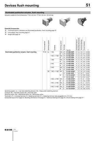
Devices flush mounting Illuminated pushbutton actuator, flush mounting Actuators usable for front dimensions: b 24 x 24 mm | a 24 x 30 mm | 25 mm dia.
Essential Accessories: Front bezel set for Indicators and Illuminated pushbutton, flush mounting page 25
d d d
Lens plastic, flush mounting page 21 Single-LED page 30
2 NC 2 NO SA
1 NC + 1 NO
M 2 NC + 2 NO 3 NC + 3 NO 4 NC + 4 NO
MA M MA M MA M
Component layout
Typ-Nr. 51-486.036F 51-456.036F 51-483.036F 51-453.036F 51-485.036F 51-455.036F 51-482.036F 51-452.036F 51-481.036F 51-451.036F 51-281.0252F 51-281.022F 51-151.0252F 51-151.022F 51-282.0252F 51-152.0252F 51-283.0252F 51-153.0252F 51-284.0252F 51-154.0252F
4 4 4 4 4 4 4 4 4 4
Circuit drawing
1 NO
UT UT UT UT UT UT UT UT UT UT S S1 S S1 S S S S S S
Technical drawing
1 NC + 1 NO
MA M MA M MA M MA M MA M MA
Mounting dimensions
1 NC
Terminals
LL
Switching action
IP 65
Contacts
Switching system
Illuminated pushbutton actuator, flush mounting
Front protection
Continuation see next page
e
3 3 3 3 3 3 3 3 3 3 3 3 3 3 3 3 3 3 3 3
16 16 16 16 16 16 16 16 16 16 16 16 16 16 16 16 16 16 16 16
11 57 14 60 13 59 12 58 15 61 10 7 56 53 6 52 3 49 2 48
0.006 0.006 0.006 0.006 0.006 0.006 0.006 0.006 0.006 0.006 0.005 0.007 0.005 0.007 0.008 0.008 0.010 0.010 0.012 0.012
Switching system: LL = Low level switching element, SA = Snap-action switching element Contacts: NC = Normally closed, NO = Normally open Switching action: MA = Maintained action, M = Momentary action Terminals: UT = Universal terminal, S = Soldering terminal, S1 = Soldering terminal (also pluggable 2.8 x 0.5 mm) Component layout from page 40, Mounting dimensions from page 41, Technical drawing from page 42, Circuit drawing from page 47
14 01.2010