DPV vertical multistage pumps 60 hz - technical data dp pumps

Page 1

Technical specification booklet series: DPV(C/S) 2 - 4 - 6 - 10 - 15 - 25 - 40 - 60 - 85 - 125 60 Hz (DIN/IEC)
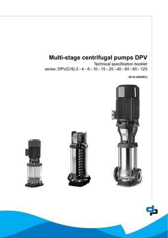
Multi-stage centrifugal pumps DPV

performance curve DPV(C/S) 15 C - 60Hz - 2 pole (3500 rpm)..........................................18

2.12Hydraulic performance curve DPV(C/S) 15 C - 60Hz - 4 pole (1750 rpm)..........................................19

2.13Hydraulic performance curve DPV(C/S) 25 B - 60Hz - 2 pole (3500 rpm)...........................................20

2.14Hydraulic performance curve DPV(C/S) 25 B - 60Hz - 4 pole (1750 rpm)...........................................21

2.15Hydraulic performance curve

2.16Hydraulic performance

2.17Hydraulic performance curve

2.18Hydraulic performance curve

40 B - 60Hz - 2 pole (3500 rpm)...........................................22

40 B - 60Hz - 4 pole (1750 rpm)...........................................23

60 B - 60Hz - 2 pole (3500 rpm)...........................................24

60 B - 60Hz - 4 pole (1750 rpm)...........................................25

2
of Contents 1Pump introduction 1.1General..................................................................................................................................................4 1.2Model key...............................................................................................................................................4 1.3Operation...............................................................................................................................................5 1.4Measuring, draining and venting............................................................................................................6 1.5Working range........................................................................................................................................6 1.6Basic material variants...........................................................................................................................7 1.7Pump bearing.........................................................................................................................................7 1.8Modular selection...................................................................................................................................8 1.9Approvals...............................................................................................................................................8 2Performance characteristics 2.1Performance range................................................................................................................................9 2.2Performance curve details.....................................................................................................................9 2.3Minimum efficiency index.....................................................................................................................10 2.4Performance with variable frequency drive..........................................................................................10 2.5How to read the values from the curves...............................................................................................11 2.6Hydraulic performance curve DPV(C/S) 2 B - 60Hz - 2 pole (3500 rpm).............................................13 2.7Hydraulic performance curve DPV(C/S) 4 B - 60Hz - 2 pole (3500 rpm).............................................14 2.8Hydraulic performance curve DPV(C/S) 6 B - 60Hz - 2 pole (3500 rpm).............................................15 2.9Hydraulic performance curve DPV(C/S) 10 B - 60Hz - 2 pole (3500 rpm)...........................................16 2.10Hydraulic performance curve DPV(C/S) 10 B - 60Hz - 4 pole (1750 rpm)...........................................17 2.11Hydraulic
Table
DPV(C/S)
curve DPV(C/S)
DPV(C/S)
2.19Hydraulic performance curve DPV(C/S) 85 B - 60Hz - 2 pole (3500 rpm)...........................................26 2.20Hydraulic performance curve DPV(C/S) 85 B - 60Hz - 4 pole (1750 rpm)...........................................27 2.21Hydraulic performance curve DPV(C/S) 125 B - 60Hz - 2 pole (3500 rpm).........................................28 3Low NPSH impeller 3.1General................................................................................................................................................30 3.2Risks of cavitation:...............................................................................................................................30 3.3Benefits of using low NPSH impeller:..................................................................................................30 3.4Consequences by using a low NPSH impeller:....................................................................................30 3.5Calculation of NPSHa..........................................................................................................................30 3.6Low NPSH curve DPV(C/S) 2 B - 60Hz - (3500 rpm)..........................................................................32 3.7Low NPSH curve DPV(C/S) 4 B - 60Hz - (3500 rpm)..........................................................................33 3.8Low NPSH curve DPV(C/S) 6 B - 60Hz - (3500 rpm)..........................................................................34 3.9Low NPSH curve DPV(C/S) 10 B - 60Hz - (3500 rpm)........................................................................35 3.10Low NPSH curve DPV(C/S) 10 B - 60Hz - (1750 rpm)........................................................................36 3.11Low NPSH curve DPV(C/S) 15 C - 60Hz - (3500 rpm)........................................................................37 3.12Low NPSH curve DPV(C/S) 15 C - 60Hz - (1750 rpm)........................................................................38 3.13Low NPSH curve DPV(C/S) 25 B - 60Hz - (3500 rpm)........................................................................39 3.14Low NPSH curve DPV(C/S) 25 B - 60Hz - (1750 rpm)........................................................................40 3.15Low NPSH curve DPV(C/S) 40 B - 60Hz - (3500 rpm)........................................................................41 3.16Low NPSH curve DPV(C/S) 40 B - 60Hz - (1750 rpm)........................................................................42
DPV(C/S)
3 4Dimensions 4.1DPV(C/S) 2 B - 60Hz - 2 pole - DIN.....................................................................................................44 4.2DPV(C/S) 4 B - 60Hz - 2 pole - DIN.....................................................................................................46 4.3DPV(C/S) 6 B - 60Hz - 2 pole - DIN.....................................................................................................48 4.4DPV(C/S) 10 B - 60Hz - 2 pole - DIN...................................................................................................50 4.5DPV(C/S) 10 B - 60Hz - 4 pole - DIN...................................................................................................52 4.6DPV(C/S) 15 C - 60Hz - 2 pole - DIN...................................................................................................54 4.7DPV(C/S) 15 C - 60Hz - 4 pole - DIN...................................................................................................56 4.8DPV(C/S) 25 B - 60Hz - 2 pole - DIN...................................................................................................58 4.9DPV(C/S) 25 B - 60Hz - 4 pole - DIN...................................................................................................60 4.10DPV(C/S) 40 B - 60Hz - 2 pole - DIN...................................................................................................62 4.11DPV(C/S) 40 B - 60Hz - 4 pole - DIN...................................................................................................64 4.12DPV(C/S) 60 B - 60Hz - 2 pole - DIN...................................................................................................66 4.13DPV(C/S) 60 B - 60Hz - 4 pole - DIN...................................................................................................68 4.14DPV(C/S) 85 B - 60Hz - 2 and 4 pole - DIN.........................................................................................70 4.15DPV(C/S) 125 B - 60Hz - 2 pole - DIN.................................................................................................72 5Seals 5.1Mechanical seal option specifications..................................................................................................74 6Motors and motor options 6.1General................................................................................................................................................75 6.2Options.................................................................................................................................................75 6.3Motor data 3 phase, 2 and 4 pole........................................................................................................76 7Accessories 7.1Thrust bearing housing (optional)........................................................................................................78 8Materials 8.1Parts overview.....................................................................................................................................79 9Medium handled 9.1Medium handled..................................................................................................................................92

1Pump introduction

1.1General

The vertical, single or multi-stage centrifugal pump series are designed for pumping clean, or lightly aggressive, watery mediums.

Suction and discharge of the pump are in-line, making the pump easy to install.

The hydraulic assembly is driven by an electric motor. All hydraulic parts of the pump are made of stainless steel.

The vertical multi-stage centrifugal DPV pumps are produced by Duijvelaar pompen.

1.2Model key

LabelDP

Material/ Construction VC

V

VM

VS

Connections E

Product Label

Cast Iron pump foot and top bracket hydr. 1.4301 / AISI 304

All wetted parts Stainless Steel 1.4301 / AISI 304

All wetted parts Stainless Steel 1.4301 / AISI 304 with closed coupled motor

All wetted parts Stainless Steel 1.4401 / AISI 316

Male thread (with non-return valve insert)

Oval flange with female thread

Round flange V

F

Victaulic connections T

Tri-clamp connections

85 Capacity in m3/h at Q.opt

/3

Number of stages

/3-1Number of stages of which one stage with reduced head

LLow NPSH impeller (model 2,4,6,10,15,25 en 40)

Vtwo stages of which one stage with reduced head and one impeller low NPSH

Wthree stages of which two stages with reduced head and one impeller low NPSH B/CDesign version

4
20090719 DPV 2,4,6 B DPV 10 B,15 C DPV 25,40,60,85,125 B
Table 1: Model key Example DPVSF 85/3-1 B DP VS F 85 /3 -1 B

1.3Operation

During centrifugal operation of the pump a negative pressure is created at the inlet of the impeller. This negative pressure enables the medium to enter the pump at the suction connection (A).

Every stage (B) consists of an impeller and diffuser. The passage of this stage determines the capacity of the pump. The diameter of the stages is related to the centrifugal forces and its “stage pressure”: the more stages, the more pressure. This total capacity and raised pressure will be guided to the outside of the pump, between the pump stages and the outer sleeve (C) and the medium will leave the pump at the discharge connection (D).

5
20080190 A D A E F G G B C
Figure 1: DPVF 85

1.4Measuring, draining and venting

The pump is provided with plugs for measuring, draining and venting.

Connection (E) is meant to drain the inlet part of the pump. Or to measure the inlet / suction pressure using a G ¼ connection.

Connection (F) is meant to drain the outlet part of the pump. Or to measure the discharge pressure using a G ¼ connection.

Connections (G) are meant to vent the pump system when the pump is not in operation. Or to measure the discharge pressure of the pump using a G 3/8 connection.

1.5Working range

The working range is depending on the application and a combination of pressure and temperature. For specific and detailed limits please consult the working ranges as described in the chapter 1.8 Modular selection. The overall working range of the pumps can be summarised as follows:

Table 2: Specification of the working range

1.5.1Minimum capacity

For minimum capacity at medium temperature of 20 oC, see table: Minimum capacity (Qmin); for higher temperatures, see table 3.

To prevent the pump from overheating, gathering gas, cavitation etc. a minimum capacity has to be secured. The minimum capacity corresponds to all percentage of the optimum flow Qopt in relation to the temperature of the liquid pumped.

1.If the ambient temperature exceeds the above value or the motor is located more than 1000 m above sea level, the motor cooling is less effective and could require an adapted motor power. See table 5: Motor load dep. sea level or amb. temp or please contact your supplier for more detailed advice.

2.Deviation in viscosity and/or density could require an adapted motor power. Please contact your supplier for more detailed advice.

3.The free space above the motor cooling fan must be at least 1/4 of the diameter of the inlet of the cooling fan in order to have a sufficient flow of (cooling) air.

4.Pumps that are intended for 50Hz operation, may not be connected to 60Hz power supply.

6
Table 3: Minimum capacity (Qmin)
Pump type DPV note Ambient temperature [°C]-20 up to 40/50 1
Table 4: Minimum capacity vs.temperature (in % of Q optimum)
Minimum inlet pressureNPSHreq. + 1m Viscosity [cSt] 1-100 2
Density [kg/m3] 1000-2500 2 Cooling forced motor cooling 3
Minimum frequency [Hz] 30 Maximum frequency [Hz] 60 4
Allowable size of solids pumped 5µm to 1mm size Qmin [m3/h] 50 Hz 60 Hz 2 pole 4 pole 2 pole 4 pole 20,2 0,2 40,4 0,5 60,6 0,8 101,10,51,30,6 151,90,92,31,1 252,81,43,11,6 404 1,94,92,3 605,32,66,53,2 858,54,310,25,1 12513,1 15,8 3675 0 5 10 15 20 25 30 35 40 405060708090100110120130140 Q [%] o

1.5.2Ambient temperature and higher altitude

If the ambient temperature exceeds the above value, or if the motor is located more than 1000 m above sea level, the motor cooling is less effective and could require an adapted motor power. See below table for the increased percentage of the motor power or contact your supplier for more detailed advice.

Table

1.6Basic material variants

1.7Pump bearing

Medium lubricated stage bearing Tungsten Carbide against Ceramic Optional pump bearing Tuc/TuC:

In case of severe applications or using conditions, such as hot water, boiler feed (max 140 oC or when the pump experiences un avoidable dry running for a short time. The standard ceramic bearing material can be replaced / exchanged by a more resistant TuC/TuC bearing material.

Due to the specific material characteristics of Tungsten Carbide, the TuC/TuC material is even more resistant for the above mentioned severe conditions and will enhance the durability and lifecycle of the pump.

When combining the use of the optional TuC/TuC bearing material and the optional low NPSH kit, the pump can be made even more suitable for the above mentioned severe applications or using conditions.

The optional combinations TuC/TuC bearing material and low NPSH kit are available for the vertical pump models DPVCF 2,4,6,10,15,25 and 40.

Up to now only the optional TuC/TuC bearing material is available for pump models DPVCF 2 up to and including 125.

For other possible pump options or features, please contact our sales department.

7
5: Increase of required motor power Table 6: Basic material variants
Ambient temperature [°C] Above sea level [m] Increase of required power 40 10000% 45 16252% 50 22505% 55 287511% 60 350018% 65 412525% 70 475033%
V 1.43011.4308EPDM VS 1.44041.4408FPM VC 2-60 & 1251.4301JS1030EPDM VC 851.4301JL1040EPDM
Model Hydraulic Casing Sealing

1.8Modular selection

To suit almost every application the pump is assembled out of modules which can be selected depending on the required working range. Basic modules are:

• Basic pump model, which defines the capacity, pressure and basic material.

Temperature range -20 up to 140 oC, with the exception of the DPV 125 this pump can be used upto 120 oC.

• Connections, which define the suction and discharge connection as well as the base plate. VE casing (with non return valve) max. temperature 90 oC. Other connections have same temperature range as basic pump model.

• Sealings, which define the elastomers, the mechanical seal and the shaft seal type.

Temperature range, see chapter 5.1

• Electric motor, which defines all requirements of the motor such as motor size, power, voltage, frequency and all possible motor accessories. Due to mono-block motor version VM, max. fluid temperature is 60 oC

1.9Approvals

CE Conformity with European Safety Directive

ACS Drinking Water Approval (F)

WRAS Drinking Water Approval (GB)

ATEX Conformity with “ATmosphères EXplosibles” Directive

8

2Performance characteristics

2.1Performance range

2.2Performance curve details

The performance diagrams give a global overview of all the pump models the shaded models are mentioned in this documentation. Detailed characteristics are given for each model showing the hydraulic efficiency, NPSHreq, and shaft power as well.

The performance of the pump depends on the number of stages. As per example:

DPV 4/2 B:model DPV 4 B2 stages with 2 full head impellers

DPV 85/4-1 Bmodel DPV 85 B4 stages with 3 full head impellers and 1 reduced impeller

The detailed performance curves are in accordance with ISO 9906: 2012 (Grade 3B).

The motors used for the measurements are calibrated motors with a specific rotational speed. Therefore the performance data, like Q/H, efficiency and shaft power used for published curves are converted to the average speed per motor power. To refine this data the published data has to be corrected accordingly.

The published curves and data mentioned on the pump are based on the following rotational speed:

The characteristics given are based on:

• De-aerated water at a temperature of 20 °C

• Density of 1,0 kg/dm3

• Kinematical viscosity of 1 mm2/s (1 cSt)

9
Figure 2: Performance range DPV(C/S) B/C 60Hz

2.3Minimum efficiency index

The minimum energy-efficiency level according to ErP regulations for water pumps is specified by the minimum efficiency index MEI. A high value indicates a high efficiency of the determined pump. From 1 January 2015 on the minimum efficiency index (MEI) for standardised water pumps is ≥0.4.

The following MEI values apply for the pump range design version B/C:

Table 7: Minimum efficiency index

Pump range Minimum Efficiency index

DPV 2BMEI ≥ 0.70

DPV 4BMEI ≥ 0.70

DPV 6BMEI ≥ 0.70

DPV 10BMEI ≥ 0.70

DPV 15CMEI ≥ 0.70

DPV 25BMEI ≥ 0.70

DPV 40BMEI ≥ 0.70

DPV 60BMEI ≥ 0.70

DPV 85BMEI ≥ 0.60

DPV 125BMEI ≥ 0.70

2.4Performance with variable frequency drive

The minimum frequency of the DP motor should be limited to 30Hz. When the rotational speed exceeds the nominal speed of the motor, make sure that the power output of the motor is suitable to drive the corresponding pump model.

The performance of the pump differs from the fixed speed performance according to the recalculation scheme.

10

2.5How to read the values from the curves

To find the required hydraulic information from the published curves, it is important to know the application in which the pump has to be installed. There are two main distinction to be made:

AFlow determined (like booster sets and cleaning) Opening taps

BPressure determined (like boiler feed and reverse osmosis systems) Facing counter pressure.

How to read the motor power

The required motor power can be read in the curve’Power input’.

Attention: the power value as mentioned in this curve is the required power per stage. For some pump types there are two lines in the curve this is related to the full impeller or reduced impeller [-1].

11
3238/08072008 1 1 2 2 Q n n Q 1 3 1 3 2 2 P n n P 1 2 1 2 2 2 NPSH n n NPSH Q 2 Q 1 1.0 2 1.0 1 1 2 11 n n 1 2 1 2 2 2 H n n H 1 2 3 4 Q Q Q Q NPSH req P/st. hydr H n1 n2 n1 n2 n2 n1 n1 n2 H2 H1
Figure 3: Performance characteristics

Pump size / no of stages. Installed motor power Capacity @ Pressure

NPSH (m)

Hydraulic efficiency (%)

Required power (P2)

Figure 4: How to read the values from the curves 3227/04072008

O Calculated duty point

 Actual hydraulic performance

A Flow determined

B Pressure determined

12

2.6Hydraulic performance curve DPV(C/S) 2 B - 60Hz - 2 pole (3500 rpm)

13
20090371 E
Figure 5: Performance curve DPV(C/S) 2 B - 60Hz - 2 pole
= 1000.0 kg/m³
Förderhöhe TDH Hauteur Prevalenza Opvoerhoogte Altura 0.00.51.01.52.02.53.03.54.0 [m³/h] 0 5 10 15 [US.gpm] 0 5 10 15 [IM.gpm] 0 50 100 150 200 250 [m] 0 200 400 600 800 [ft] 0.0 0.2 0.4 0.6 0.8 1.0 [l/s] NPSHR 0 10 [m] 0 20 [ft] Eta 0 80 % Leistungsbedarf Power Input Puiss. abs. Potenza ass. Opgenomen vermogen Potencia nec. 0.1 0.04 0.14 [kW] 0.10 0.15 [hp] 0.00.51.01.52.02.53.03.54.0 [m³/h] 2/22 3,0 kW 2/20 3,0 kW 2/18 2,2 kW 2/16 2,2 kW 2/14 2,2 kW 2/12 1,5 kW 2/9 1,1 kW 2/11 1,5 kW 2/10 1,5 kW 2/8 1,1 kW 2/7 1,1 kW 2/6 0,75 kW 2/5 0,75 kW 2/4 0,55 kW 2/3 0,37 kW 2/2 0,37 kW
Fördermenge/Flow/Débit/Portata/Capaciteit/Caudal
20090371-E/0

2.7Hydraulic performance curve DPV(C/S) 4 B - 60Hz - 2 pole (3500 rpm)

14
20090373 E
Figure 6: Performance curve DPV(C/S) 4 B - 60Hz - 2 pole
= 1000.0 kg/m³
Fördermenge/Flow/Débit/Portata/Capaciteit/Caudal
Förderhöhe TDH Hauteur Prevalenza Opvoerhoogte Altura 012345678 [m³/h] 0102030 [US.gpm] 01020 [IM.gpm] 0 50 100 150 200 250 [m] 0 200 400 600 800 [ft] 0.0 0.5 1.0 1.5 2.0 [l/s] NPSHR 0 8 [m] 0 20 [ft] Eta 0 80 % Leistungsbedarf Power Input Puiss. abs. Potenza ass. Opgenomen vermogen Potencia nec. 0.0 0.3 [kW] 0.0 0.4 [hp] 012345678 [m³/h] 4/18 5,5 kW 4/16 5,5 kW 4/14 4,0 kW 4/12 4,0 kW 4/11 3,0 kW 4/10 3,0 kW 4/9 3,0 kW 4/8 2,2 kW 4/7 2,2 kW 4/6 1,5 kW 4/5 1,5 kW 4/4 1,1 kW 4/3 0,75 kW 4/2 0,55 kW
20090373-E/0

2.8Hydraulic performance curve DPV(C/S) 6 B - 60Hz - 2 pole (3500 rpm)

15
20090375 F Fördermenge/Flow/Débit/Portata/Capaciteit/Caudal  = 1000.0 kg/m³ 20090375-F/0 Förderhöhe TDH Hauteur Prevalenza Opvoerhoogte Altura 024681012 [m³/h] 01020304050 [US.gpm] 010203040 [IM.gpm] 0 50 100 150 200 250 [m] 0 200 400 600 800 [ft] 0123 [l/s] NPSHR 0 6 [m] 0 10 [ft] Eta 0 80 % Leistungsbedarf Power Input Puiss. abs. Potenza ass. Opgenomen vermogen Potencia nec. 0.0 0.4 [kW] 0 0.4 [hp] 024681012 [m³/h] 6/18 7,5 kW 6/16 7,5 kW 6/14 5,5 kW 6/12 5,5 kW 6/11 4,0 kW 6/10 4,0 kW 6/9 4,0 kW 6/8 3,0 kW 6/7 3,0 kW 6/6 2,2 kW 6/5 2,2 kW 6/4 1,5 kW 6/3 1,1 kW 6/2 0,75 kW 6/1 0,37 kW
Figure 7: Performance curve DPV(C/S) 6 B - 60Hz - 2 pole

2.9Hydraulic performance curve DPV(C/S) 10 B - 60Hz - 2 pole (3500 rpm)

16
20101081 B
Figure 8: Performance curve DPV(C/S) 10 B - 60Hz - 2 Pole
= 1000.0 kg/m³ 20101081-B/0 Förderhöhe TDH Hauteur Prevalenza Opvoerhoogte Altura 0246810121416 [m³/h] 0204060 [US.gpm] 02040 [IM.gpm] 0 50 100 150 200 250 [m] 0 200 400 600 800 [ft] 01234 [l/s] NPSHR 5 1 [m] 10 [ft] Eta 0 80 % Leistungsbedarf Power Input Puiss. abs. Potenza ass. Opgenomen vermogen Potencia nec. 0 0.8 [kW] 0 1 [hp] 0246810121416 [m³/h] 10/15 11 kW 10/13 11 kW 10/11 7,5 kW 10/10 7,5 kW 10/9 7,5 kW 10/8 5,5 kW 10/7 5,5 kW 10/6 4 kW 10/5 4 kW 10/4 3 kW 10/3 2,2 kW 10/2 1,5 kW 10/1 0,75 kW
Fördermenge/Flow/Débit/Portata/Capaciteit/Caudal

2.10Hydraulic

17
performance curve DPV(C/S) 10 B - 60Hz - 4 pole (1750 rpm)
20101083 Fördermenge/Flow/Débit/Portata/Capaciteit/Caudal = 1000.0 kg/m³ 20101083 Förderhöhe TDH Hauteur Prevalenza Opvoerhoogte Altura 02468 m³/h 0102030 US.gpm 0102030 IM.gpm 0 10 20 30 40 50 60 66 m 0 50 100 150 200 ft 0.0 0.5 1.0 1.5 2.0 l/s NPSHR 0 1.5 m 0 4 ft Eta 0 80 % Leistungsbedarf Power Input Puiss. abs Potenza ass Opgenomen vermogen Potencia nec 0.0 0.1 kW 0.0 0.1 hp 02468 m³/h 10/15 1,5 kW 10/13 1,1 kW 10/11 1,1 kW 10/10 0,75 kW 10/9 0,75 kW 10/8 0,75 kW 10/7 0,55 kW 10/6 0,55 kW 10/5 0,55 kW 10/4 0,55 kW 10/3 0,55 kW 10/2 0,55 kW 10/1 0,55 kW
Figure 9: Performance curve DPV(C/S) 10 B - 60Hz - 4 pole

2.11Hydraulic performance curve DPV(C/S) 15 C - 60Hz - 2 pole (3500 rpm)

Figure 10: Performance curve DPV(C/S) 15 C - 60Hz - 2 pole

18
20210122 B
= 1000.0 kg/m³ 20210122-B/1 Förderhöhe TDH Hauteur Prevalenza Opvoerhoogte Altura 510152025 0 [m³/h] 120 100 80 60 40 20 0 [US.gpm] 100 80 60 40 20 0 [IM.gpm] 0 50 100 150 200 250 [m] 0 200 400 600 800 [ft] 8 6 4 2 0 [l/s] NPSHR 0 4 [m] 0 10 [ft] Eta 0 80 [%] Leistungsbedarf Power Input Puiss. abs. Potenza ass. Opgenomen vermogen Potencia nec. 2 [kW] 0 0 2 [hp] 0 5 10 15 20 25 [m³/h] W 8.5 k 11 1 15/ kW 8.5 10 1 15/ kW 1515/9 8kW 1515/ 7kW 1515/ kW 11 15/6 kW 5 11 15/ kW 7.515/4 5 3kkW 5.15/ 15/2 4 kW kW 1 2.2 15/ *Power input based on a V 15/3 C
Fördermenge/Flow/Débit/Portata/Capaciteit/Caudal
of this hydraulic speed design

2.12Hydraulic performance curve DPV(C/S) 15 C - 60Hz - 4 pole (1750 rpm)

19
20210124 A Fördermenge/Flow/Débit/Portata/Capaciteit/Caudal  = 1000.0 kg/m³ 20210124-A/0 Förderhöhe TDH Hauteur Prevalenza Opvoerhoogte Altura 02468101214 [m³/h] 0204060 [US.gpm] 01020304050 [IM.gpm] 0 10 20 30 40 50 60 [m] 0 50 100 150 200 [ft] 01234 [l/s] NPSHR 0 1 [m] 0 2 [ft] Eta 0 80 % Leistungsbedarf Power Input Puiss. abs. Potenza ass. Opgenomen vermogen Potencia nec. 0.0 0.2 [kW] 0.0 0.3 [hp] 02468101214 [m³/h] 15/11 3 kW 15/10 2.2 kW 15/9 2.2 kW 15/8 2.2 kW 15/7 1.5 kW 15/6 1.5 kW 15/5 1.1 kW 15/4 1.1 kW 15/3 0.75 kW 15/2 0.55 kW 15/1 0.55 kW
input
V
Figure 11: Performance curve DPV(C/S) 15 C - 60Hz - 4 pole
*Power
based on a 15/3 C of this hydraulic speed design

2.13Hydraulic performance curve DPV(C/S) 25 B - 60Hz - 2 pole (3500 rpm)

20
20120432 A Fördermenge/Flow/Débit/Portata/Capaciteit/Caudal  = 1000.0 kg/m³ 20120432-A/0 Förderhöhe TDH Hauteur Prevalenza Opvoerhoogte Altura 010203040 [m³/h] 0 50 100 150 200 [US.gpm] 0 50 100 150 [IM.gpm] 0 20 40 60 80 100 120 140 160 180 200 [m] 0 200 400 600 [ft] 024681012 [l/s] NPSHR 0 8 [m] 0 20 [ft] Eta 0 80 % Leistungsbedarf Power Input Puiss. abs. Potenza ass. Opgenomen vermogen Potencia nec. 0 3 [kW] 0 4 [hp] 010203040 [m³/h] 25/7 22 kW 25/6 18,5 kW 25/5 15 kW 25/4 15 kW 25/3 11 kW 25/2 7,5 kW 25/1 3 kW
Figure 12: Performance curve DPV(C/S) 25 B - 60Hz - 2 pole

2.14Hydraulic performance curve DPV(C/S) 25 B - 60Hz - 4 pole (1750 rpm)

21
20120433 A
Figure 13: Performance curve DPV(C/S) 25 B - 60Hz - 4 pole
Förderhöhe TDH Hauteur Prevalenza Opvoerhoogte Altura 0 5 10 15 20 [ ] 020406080100 [US.gpm] 020406080 [IM.gpm] 0 20 40 60 80 95 [m] 0 100 200 300 [ft] 0246 [l/s] NPSHR 0 4 [m] 0 10 [ft] Eta 0 80 % Leistungsbedarf Power Input Puiss. abs. Potenza ass Opgenomen vermogen Potencia nec. 0.0 0.4 [kW] 0 0.4 [hp] 0 5 10 15 20 [ ] 25/12 4 KW 25/11 4 kW 25/10 4 kW 25/9 4 kW 25/8 3 kW 25/7 3 kW 25/6 2.2 kW 25/5 2.2 kW 25/4 1.5 kW 25/3 1.1 kW 25/2 1.1 kW 25/1 1.1 kW
Fördermenge/Flow/Débit/Portata/Capaciteit/Caudal

2.15Hydraulic performance curve DPV(C/S) 40 B - 60Hz - 2 pole (3500 rpm)

22
20130545 B Fördermenge/Flow/Débit/Portata/Capaciteit/Caudal  = 1000.0 kg/m³ 20130545-B/0 Förderhöhe TDH Hauteur Prevalenza Opvoerhoogte Altura 10 20 30 40 50 60 0 70 [m³/h] 300 200 100 0 [US.gpm] 250 200 150 100 50 0 [IM.gpm] 0 50 100 150 200 [m] 0 200 400 600 [ft] 15 10 5 0 [l/s] NPSHR 0 10 [m] 0 20 [ft] Eta 0 100 % Leistungsbedarf Power Input Puiss. abs. Potenza ass. Opgenomen vermogen Potencia nec. 0 6 [kW] 0 8 [hp] 70 0102030405060 [m³/h] /kW 37 6-2 40 W 7 k6 3 40/ kW 30 40/5-2 40/5 30 kW W 0 k4 3 40/ W ,5 k 18 40/3-2 kW 8,5 3 1 40/ 40/2-2 11 kW W 5 k2 1 40/ 5 kW k 5, 40/1-1 40/1 7,5 kW 40/4-2 22 kW
Figure 14: Performance curve DPV(C/S) 40 B - 60Hz - 2 pole

2.16Hydraulic performance curve DPV(C/S) 40 B - 60Hz - 4 pole (1750 rpm)

23
20130547 A Fördermenge/Flow/Débit/Portata/Capaciteit/Caudal = 1000.0 kg/m³ 20130547-A Förderhöhe TDH Hauteur Prevalenza Opvoerhoogte Altura 0 5 10 15 20 25 30 35 [m³/h] 0 50 100 150 [US.gpm] 020406080100120 [IM.gpm] 0 20 40 60 80 [m] 0 100 200 300 [ft] 02468 [l/s] NPSHR 0 3 [m] 0 5 [ft] Eta 0 100 % Leistungsbedarf Power Input Puiss. abs. Potenza ass. Opgenomen vermogen Potencia nec. 0 0.8 [kW] 0 1 [hp] 0 5 10 15 20 25 30 35 [m³/h] 40/10 7,5 kW 40/9 7,5 kW 40/8 7,5 kW 40/7 5,5 kW 40/6 5,5 kW 40/5 4 kW 40/4 4 kW 40/3 3 kW 40/2 2,2 kW
Figure 15: Performance curve DPV(C/S) 40 B - 60Hz - 4 pole

2.17Hydraulic performance curve DPV(C/S) 60 B - 60Hz - 2 pole (3500 rpm)

24
20130549 D Fördermenge/Flow/Débit/Portata/Capaciteit/Caudal  = 1000.0 kg/m³ 20130549-D/0 Förderhöhe TDH Hauteur Prevalenza Opvoerhoogte Altura 20 40 60 80 0 [m³/h] 400 300 200 100 0 [US.gpm] 300 200 100 0 [IM.gpm] 0 50 100 150 200 [m] 0 200 400 600 [ft] 25 20 15 10 5 0 [l/s] NPSHR 0 6 [m] 0 10 [ft] Eta 0 100 % Leistungsbedarf Power Input Puiss. abs. Potenza ass. Opgenomen vermogen Potencia nec. 0 10 [kW] 0 10 [hp] 020406080 [m³/h] 45 kW 60/5 W 2 45 k 60/57 kW 60/43 W 2 30 k 60/460/3 30 kW W 2 22 k 60/3W 18,5 k 60/2 W 2 15 k 60/211 kW 60/1 kW 1 7,5 60/1-1
Figure 16: Performance curve DPV(C/S) 60 B - 60Hz - 2 pole

2.18Hydraulic performance curve DPV(C/S) 60 B - 60Hz - 4 pole (1750 rpm)

25
20130551 B
Figure 17: Performance curve DPV(C/S) 60 B - 60Hz - 4 pole
= 1000.0 kg/m³ 20130551-B/0 Förderhöhe TDH Hauteur Prevalenza Opvoerhoogte Altura 10 20 30 40 0 50 [m³/h] 200 150 100 50 0 [US.gpm] 150 100 50 0 [IM.gpm] 0 10 20 30 40 50 60 70 80 [m] 0 150 200 250 100 [ft] 50 12 10 8 6 4 2 0 [l/s] NPSHR 0 3 [m] 0 5 [ft] Eta 0 100 % Leistungsbedarf Power Input Puiss. abs. Potenza ass. Opgenomen vermogen Potencia nec. 0 1.5 [kW] 0 2 [hp] 01020304050 [m³/h] kW 7,560/7 W 7,5 60/6k 60/5 5,5 kW k 4W 5,5 60/ W 4 k 60/3 W 3 k 60/2
Fördermenge/Flow/Débit/Portata/Capaciteit/Caudal

2.19Hydraulic performance curve DPV(C/S) 85 B - 60Hz - 2 pole (3500 rpm)

26
20080077 C
= 1000.0 kg/m³ 20080077-C/0 Förderhöhe TDH Hauteur Prevalenza Opvoerhoogte Altura 0 20 40 60 80 100120 140 [m³/h] 0 200 400 600 [US.gpm] 0 100 200 300 400 500 [IM.gpm] 0 20 40 60 80 100 120 140 [m] 0 100 200 300 400 500 [ft] 010203040 [l/s] NPSHR 0 10 [m] 0 20 [ft] Eta 0 80 % Leistungsbedarf Power Input Puiss. abs. Potenza ass. Opgenomen vermogen Potencia nec. 0 15 [kW] 0 20 [hp] 0 20 40 60 80 100120 140 [m³/h] 85/3 45 kW 85/3-1 37 kW 85/4-2 45 kW 85/3-2 30 kW 85/2-1 22 kW 85/2-2 18,5 kW 85/2 30 kW 85/1-1 11 kW -1 85/1 15 kW
Figure 18: Performance curve DPV(C/S) 85 B - 60Hz - 2 pole Fördermenge/Flow/Débit/Portata/Capaciteit/Caudal

2.20Hydraulic performance curve DPV(C/S) 85 B - 60Hz - 4 pole (1750 rpm)

27
20080537 B
= 1000.0 kg/m³ 20080537-B/1 Förderhöhe TDH Hauteur Prevalenza Opvoerhoogte Altura 010203040506070 m³/h 0 100 200 300 US.gpm 0 50 100 150 200 250 IM.gpm 15 20 25 30 35 13 37 m 60 80 100 120 ft 0 5 10 15 l/s NPSHR 0 1.5 m 0 4 ft Eta 0 80 % Leistungsbedarf Power Input Puiss. abs Potenza ass Opgenomen vermogen Potencia nec 1 0.4 1.6 kW 2 1 hp 010203040506070 m³/h 85/4-2 5,5 kW 85/3-1 5,5 kW 85/3 5,5 kW -1
Figure 19: Performance curve DPV(C/S) 85 B - 60Hz - 4 pole
Fördermenge/Flow/Débit/Portata/Capaciteit/Caudal

2.21Hydraulic performance curve DPV(C/S) 125 B - 60Hz - 2 pole (3500 rpm)

28
20150417 B
= 1000.0 kg/m³ 20150417-B/0 Förderhöhe TDH Hauteur Prevalenza Opvoerhoogte Altura 020406080100120140160180200 [m³/h] 0 200 400 600 800 [US.gpm] 0 200 400 600 [IM.gpm] 20 40 60 80 100 [m] 100 200 300 [ft] 02040 [l/s] NPSHR 0 15 [m] 0 40 [ft] Eta 0 100 % Leistungsbedarf Power Input Puiss. abs. Potenza ass. Opgenomen vermogen Potencia nec. 0 20 [kW] 0 30 [hp] 020406080100120140160180200 [m³/h] 125/2 45 kW 125/2-2 30 kW -1 125/1 22 kW
Figure 20: Performance curve DPV(C/S) 125 B - 60Hz - 2 pole
Fördermenge/Flow/Débit/Portata/Capaciteit/Caudal
29

3Low NPSH impeller

3.1General

Low NPSH impeller

For the pump type series DPV(S/C)(F) 2, 4, 6, 10, 15, 25 and 40 it is now possible to have a low NPSH solution as option. This solution based on a new designed low NPSH impeller and modified stage casing the NPSH curve of the pump will have much better values throughout its raster. This can prevent cavitation in the pump in case of critical inlet conditions.

Cavitation is the process of forming vapour-filled cavities within the liquid in areas where the available pressure has been reduced below a certain critical value. This also happens in case the pressure drops below the vapour pressure of the liquid. When the pressure raises these cavities will implode to become fluid again. These implosions generate pressure waves which are transmitted to the surfaces of the hydraulic pump parts and can damage the material. This phenomenon is called incipient cavitation and is characterized by a metallic noise produced by the hammering on the material.

3.2Risks of cavitation:

Reduced lifetime of the pump due to damaged parts and unbalanced hydraulics.

Excessive wear of pump parts or motor bearings. Insufficient cooling and/or lubrication of the mechanical seal and pump bearing.

3.3Benefits of using low NPSH impeller:

More suitable in critical inlet conditions. Easy adaption to non-optimized application parameters.

The suction lift (Hp) can be less critical (e.g. the frame height of the de-aerating tank in case of boiler feed can be reduced)

3.4Consequences by using a low NPSH impeller:

No change in pump height or connection.

Slight adjustments on the performance curve, see curves as published on pages 32 to 42.

3.5Calculation of NPSHa

Calculation NPSHa > NPSHr + 0,5

Check if cavitation can be expected.

Hb + Ho + Hp - HV - Hi > NPSHr + 0,5

Hb = barometric pressure in mwc

Ho = over pressure (in case of closed tank) in mwc

Hp = suction lift in mwc

Hv =- vapour pressure in mwc

Hl = friction loss in pipe work and accessories in mwc

NPSHr = net positive suction head of the pump

0.5 = safety factor

30

Atmosferic pressure + 10.3 mwc

Overpressure in degassing tank + …… .mwc

Positive height of degassing tank or vessel + ……. mwc

Vapour pressure of feed water (see table)in degassing tank in case of boiler feed - ……. mwc

Loss of pressure in suction piping and strainer - ……. mwc

Safety factor - 0.5 mwc

NPSHr at duty point (see pumpcurve) - ……. mwc

Minimal positive pressure x mwc

If 'x' is positive there is no cavitation to be expected

If 'x' is negative cavitation can be expected, to avoid this the low NPSH impeller could solve this problem. Otherwise one of the other values can be changed so the outcome will be positive.

31
Table 8: Calculation NPSHa Table 9: Vapour pressure water:

3.6Low NPSH curve DPV(C/S) 2 B - 60Hz - (3500 rpm)

32
20170343 B
= 1000.0 kg/m³ 20170343-B/0 Förderhöhe TDH Hauteur Prevalenza Opvoerhoogte Altura 01234 [m³/h] 0 5 10 15 [US.gpm] 0 5 10 15 [IM.gpm] 0 50 100 150 200 250 [m] 0 200 400 600 800 [ft] 0.0 0.2 0.4 0.6 0.8 1.0 1.2 [l/s] NPSHR 0 1.5 [m] 0 4 [ft] Eta 0 60 % Leistungsbedarf Power Input Puiss. abs. Potenza ass. Opgenomen vermogen Potencia nec. 0.0 0.15 [kW] 0.0 0.2 [hp] 01234 [m³/h] 2/22 3,0 kW 2/20 3,0 kW 2/18 2,2 kW 2/16 2,2 kW 2/14 2,2 kW 2/12 1,5 kW 2/11 1,5 kW 2/10 1,5 kW 2/9 1,1 kW 2/8 1,1 kW 2/7 1,1 kW 2/6 0,75 kW 2/5 0,75 kW 2/4 0,55 kW 2/3 0,37 kW 2/2 0,37 kW
Figure 21: curve DPV(C/S) 2 B - 60Hz - 2 pole
Fördermenge/Flow/Débit/Portata/Capaciteit/Caudal

3.7Low NPSH curve DPV(C/S) 4 B - 60Hz - (3500 rpm)

33
20170344 B
= 1000.0 kg/m³ 20170344-B/0 Förderhöhe TDH Hauteur Prevalenza Opvoerhoogte Altura 012345678 [m³/h] 0102030 [US.gpm] 0102030 [IM.gpm] 0 50 100 150 200 250 [m] 0 200 400 600 800 [ft] 0.0 0.5 1.0 1.5 2.0 [l/s] NPSHR 0 4 [m] 0 10 [ft] Eta 0 80 % Leistungsbedarf Power Input Puiss. abs. Potenza ass. Opgenomen vermogen Potencia nec. 0.0 0.3 [kW] 0.0 0.4 [hp] 012345678 [m³/h] 4/18 5,5 kW 4/16 5,5 kW 4/14 4,0 kW 4/12 4,0 kW 4/11 3,0 kW 4/10 3,0 kW 4/9 3,0 kW 4/8 2,2 kW 4/7 2,2 kW 4/6 1,5 kW 4/5 1,5 kW 4/4 1,1 kW 4/3 0,75 kW 4/2 0,55 kW
Figure 22: curve DPV(C/S)4 B - 60Hz - 2 pole
Fördermenge/Flow/Débit/Portata/Capaciteit/Caudal

3.8Low NPSH curve DPV(C/S) 6 B - 60Hz - (3500 rpm)

34
20170470 A Fördermenge/Flow/Débit/Portata/Capaciteit/Caudal  = 1000.0 kg/m³ 20170470-A/0 Förderhöhe TDH Hauteur Prevalenza Opvoerhoogte Altura 246810 0 12 [m³/h] 50 40 30 20 10 0 [US.gpm] 40 30 20 10 0 [IM.gpm] 0 50 100 150 200 250 [m] 0 200 400 600 800 [ft] 3 2 1 0 [l/s] NPSHR 0 2 [m] 0 5 [ft] Eta 0 80 % Leistungsbedarf Power Input Puiss. abs. Potenza ass. Opgenomen vermogen Potencia nec. 0.0 0.4 [kW] 0 0.4 [hp] 0 12 246810 [m³/h] W 7,5 k 6/18 kW 7,56/16 W 5,5 k 6/14 6/12 5,5 kW W 4,0 k 6/11 W 4,0 k 6/10 W ,0 k 6/9 4 W ,0 k 6/8 3 6/7 3,0 kW W ,2 k 6/6 2 W ,2 k 6/5 2 W ,5 k 6/4 1 W 1,1 k 6/3 6/2 0,75 kW W ,37 k 6/1 0
Figure 23: curve DPV(C/S)6 B - 60Hz - 2 pole

3.9Low NPSH curve DPV(C/S) 10 B - 60Hz - (3500 rpm)

35
20161454 B
= 1000.0 kg/m³
Förderhöhe TDH Hauteur Prevalenza Opvoerhoogte Altura 0246810121416 [m³/h] 0204060 [US.gpm] 0204060 [IM.gpm] 0 50 100 150 200 250 [m] 0 200 400 600 800 [ft] 01234 [l/s] NPSHR 0 2 [m] 0 5 [ft] Eta 0 80 % Leistungsbedarf Power Input Puiss. abs. Potenza ass. Opgenomen vermogen Potencia nec. 0 0.8 [kW] 0 1 [hp] 0246810121416 [m³/h] 10/15 11 kW 10/13 11 kW 10/11 7,5 kW 10/10 7,5 kW 10/9 7,5 kW 10/8 5,5 kW 10/7 5,5 kW 10/6 4 kW 10/5 4 kW 10/4 3 kW 10/3 2,2 kW 10/2 1,5 kW 10/1 0,75 kW
Figure 24: curve DPV(C/S) 10 B - 60Hz - 2 pole Fördermenge/Flow/Débit/Portata/Capaciteit/Caudal
20161454-B/0

3.10Low NPSH curve DPV(C/S) 10 B - 60Hz - (1750 rpm)

36
20161455 B
= 1000.0 kg/m³ 20161455-B/0 Förderhöhe TDH Hauteur Prevalenza Opvoerhoogte Altura 02468 [m³/h] 0102030 [US.gpm] 0102030 [IM.gpm] 0 10 20 30 40 50 60 [m] 0 50 100 150 200 [ft] 0.0 0.5 1.0 1.5 2.0 [l/s] NPSHR 0 0.6 [m] 0 1 [ft] Eta 0 80 % Leistungsbedarf Power Input Puiss. abs. Potenza ass. Opgenomen vermogen Potencia nec. 0.0 0.08 [kW] 0.0 0.1 [hp] 02468 [m³/h] 10/15 1,5 kW 10/13 1,1 kW 10/11 1,1 kW 10/10 0,75 kW 10/9 0,75 kW 10/8 0,75 kW 10/7 0,55 kW 10/6 0,55 kW 10/5 0,55 kW 10/4 0,55 kW 10/3 0,55 kW 10/2 0,55 kW 10/1 0,55 kW
Figure 25: curve DPV(C/S) 10 B - 60Hz - 4 pole
Fördermenge/Flow/Débit/Portata/Capaciteit/Caudal

3.11Low NPSH curve DPV(C/S) 15 C - 60Hz - (3500 rpm)

Figure 26: curve DPV(C/S) 15 C - 60Hz - 2 pole

37
20210126 B
= 1000.0 kg/m³ 20210126-B/1 Förderhöhe TDH Hauteur Prevalenza Opvoerhoogte Altura 510152025 0 [m³/h] 120 100 80 60 40 20 0 [US.gpm] 100 80 60 40 20 0 [IM.gpm] 0 50 100 150 200 250 [m] 0 200 400 600 800 [ft] 8 6 4 2 0 [l/s] NPSHR 0 3 [m] 0 5 [ft] Eta 0 80 % Leistungsbedarf* Power Input Puiss. abs. Potenza ass. Opgenomen vermogen Potencia nec. 2 [kW] 0 0 2 [hp] 0 5 10 15 20 25 [m³/h] W 8,5 k 11 1 15/ kW 8,5 10 1 15/ 9kW 1515/ 15/8 15 kW kW 1515/7 kW 11 15/6 kW 11 15/5 4 7,5 kW k 7,k7,k7,15/ 3 5,5 kW k 5,k5,k5,15/ W 4 k 15/2 kW 1 2,2 15/
input based on a V 15/3 C
Fördermenge/Flow/Débit/Portata/Capaciteit/Caudal
*Power
of this hydraulic speed design

3.12Low NPSH curve DPV(C/S) 15 C - 60Hz - (1750 rpm)

38
20210128 Fördermenge/Flow/Débit/Portata/Capaciteit/Caudal  = 1000.0 kg/m³ 20210128/0 Förderhöhe TDH Hauteur Prevalenza Opvoerhoogte Altura 02468101214 [m³/h] 0204060 [US.gpm] 01020304050 [IM.gpm] 0 10 20 30 40 50 60 [m] 0 50 100 150 200 [ft] 01234 [l/s] NPSH 0 0.8 [m] 0 2 [ft] Eta 0 80 % Leistungsbedarf* Power Input Puiss. abs. Potenza ass. Opgenomen vermogen Potencia nec. 0.0 0.2 [kW] 0.0 0.2 [hp] 02468101214 [m³/h] 15/11 2.2 kW 15/10 2.2 kW 15/9 2.2 kW 15/8 2.2 kW 15/7 1.5 kW 15/6 1.5 kW 15/5 1.1 kW 15/4 1.1 kW 15/3 0.75 kW 15/2 0.55 kW 15/1 0.55 kW R
Figure 27: curve DPV(C/S) 15 C - 60Hz - 4 pole

3.13Low NPSH curve DPV(C/S) 25 B - 60Hz - (3500 rpm)

39
20211208 B Fördermenge/Flow/Débit/Portata/Capaciteit/Caudal  = 1000.0 kg/m³ 20211208 /1 Förderhöhe TDH Hauteur Prevalenza Opvoerhoogte Altura 010203040 m³/h 0 50 100 150 200 US.gpm 0 50 100 150 IM.gpm 0 20 40 60 80 100 120 140 160 180 200 m 0 200 400 600 ft 024681012 l/s NPSH3% 0 4 m 0 10 ft Eta 0 80 % Leistungsbedarf Power Input Puiss. abs. Potenza ass. Opgenomen vermogen Potencia nec. 0 4 kW 0 4 hp 020 30 40 10 m³/h 25/7-L 22 kW 25/6-L 18.5 kW 25/5-L 15 kW 25/4-L 15 kW 25/3-L 11 kW 25/2-L 7.5 kW 25/1-L 3 kW
Figure 28: curve DPV(C/S) 25 B - 60Hz - 2 pole

3.14Low NPSH curve DPV(C/S) 25 B - 60Hz - (1750 rpm)

40
20211210 B Fördermenge/Flow/Débit/Portata/Capaciteit/Caudal  = 1000.0 kg/m³ 20211210 /1 Förderhöhe TDH Hauteur Prevalenza Opvoerhoogte Altura 0 5 10 15 20 m³/h 020406080100 US.gpm 020406080 IM.gpm 0 20 40 60 80 m 0 100 200 300 ft 0246 l/s NPSH3% 0 1.5 m 0 4 ft Eta 0 80 % Leistungsbedarf Power Input Puiss. abs. Potenza ass. Opgenomen vermogen Potencia nec. 0.0 0.5 kW 0 0.6 hp 010 15 20 5 m³/h 25/12-L 4 kW 25/11-L 4 kW 25/10-L 4 kW 25/9-L 4 kW 25/8-L 3 kW 25/7-L 3 kW 25/6-L 2.2 kW 25/5-L 2.2 kW 25/4-L 1.5 kW 25/3-L 1.1 kW 25/2-L 1.1 kW 25/1-L 1.1 kW
Figure 29: curve DPV(C/S) 25 B - 60Hz - 4 pole

3.15Low NPSH curve DPV(C/S) 40 B - 60Hz - (3500 rpm)

41
20211015 Fördermenge/Flow/Débit/Portata/Capaciteit/Caudal  = 1000.0 kg/m³ 20211015/0 Förderhöhe TDH Hauteur Prevalenza Opvoerhoogte Altura 010203040506070 [m³/h] 0 100 200 300 [US.gpm] 0 50 100 150 200 250 [IM.gpm] 0 50 100 150 200 [m] 0 200 400 600 [ft] 0 5 10 15 [l/s] NPSHR 0 4 [m] 0 10 [ft] Eta 0 100 % Leistungsbedarf Power Input Puiss. abs. Potenza ass. Opgenomen vermogen Potencia nec. 0 6 [kW] 0 8 [hp] 010203040506070 [m³/h] 40/6 37 kW 40/6-2 37 kW 40/5 30 kW 40/5-2 30 kW 40/4 30 kW 40/4-2 22 kW 40/3 18,5 kW 40/3-2 18,5 kW 40/2 15 kW 40/1 7,5 kW -1
Figure 30: curve DPV(C/S) 40 B - 60Hz - 2 pole

3.16Low NPSH curve DPV(C/S) 40 B - 60Hz - (1750 rpm)

42
20211017
Figure 31: curve DPV(C/S) 40 B - 60Hz - 4 pole
Förderhöhe TDH Hauteur Prevalenza Opvoerhoogte Altura 51015202530 0 35 [m³/h] 150 100 50 0 [US.gpm] 120 100 80 60 40 20 0 [IM.gpm] 0 20 40 60 80 [m] 0 100 200 300 [ft] 8 6 4 2 0 [l/s] NPSHR 0 1 [m] 0 2 [ft] Eta 0 100 [ %] Leistungsbedarf Power Input Puiss. abs. Potenza ass. Opgenomen vermogen Potencia nec. 0 0.8 [kW] 0 1 [hp] 0 35 51015202530 m³/h k 7,5 /10 40W kW 7,5 40/9 kW 7,5 40/8 40/7 5,5 kW kW 5,5 40/6 W 4 k 40/5 W 4 k 40/4 0/3 3 kW k /3k/3k/3k/3 4 0/2 2 /2/2/2kW,2/2 4 ρ = 1000.0 kg/m³
Fördermenge/Flow/Débit/Portata/Capaciteit/Caudal 20211017/0
43

4Dimensions

4.1DPV(C/S) 2 B - 60Hz - 2 pole - DIN

1.All motor dimensions are only valid for Cantoni motors with efficiency class IE3 (motor power ≥ 0,75kW).

44
Table 10: VM CLOSED coupled motor construction type; IM 3619
Modelpressure class Power Motor dimensions DPVM (-E/V/T) DPVMF [kW] E1 [mm] E2 [mm] P [mm] F1 [mm] F2 [mm] Mass [kg] F1 [mm] F2 [mm] Mass [kg] 2/2PN100,37 1341074201544520 2/3 0,371341074411646621 2/4 0,551341074631648821 2/5 0,751501155282255327 2/6 0,751501155502357528 20091216-A Modelpressure class PowerMotor dimensions1
Table 11: coupled motor construction type; V18 /* Dimensions of IE3-v2 motor.
20081033-E
DPV(S)(-E/V/T) (Ecasing PN16) DPV(C/S)F [kW] E1 [mm] E2 [mm] P [mm] F1 [mm] F2 [mm] Mass [kg] F1 [mm] F2 [mm] Mass [kg] 2/2PN100,371341074782591850328422 2/3 0,371341074992801852430523 2/4 0,551341075453021857032723 2/5 0,751501155673332559235830 2/6 0,751501155893552661438030 2/7 1,11501156403762666540131 2/8 1,11501156623982668742331 2/9 1,11501156834192770844432 2/10PN161,5*2001487324513375747634 2/11 1,5*2001487534723377849734 2/12 1,5*2001487754943480051935 2/14 2,2*2001488185373684356237 2/16PN25/402,2*2001488615804188660541 2/18 2,2*2001489046234192964842 2/20 3*21515799367652101870153 2/22 3*215157103671953106174454
*Dimensions
of IE3-v2 motor.

DPV E Male threadWith non return valve insert at discharge side and pressure measurement plug at upstream side

Norm: G EN ISO 228

Size: G 6/4

Pressure Class: PN16

Option: Base plate in Cast SS 1.4308

DPV (S)

Counter flange with female thread included

DPV: Cataphoric coated cast iron

DPVS: Cast Stainless steel 1.4408

Norm: G EN ISO 228

Size: G1

Pressure Class: PN16

Option: SS 1.4308 flange and base plate

DPV (S) V Victaulic

Norm: -

Size: 42,2

Pressure Class: PN40

Option: Base plate in cast SS 1.4308

DPV (S) T Tri-Clamp

Norm: 32676

Size: DN32

Pressure Class: PN40

Option: Base plate in cast SS 1.4308

DPV C F Cast iron flange

Norm: EN 1092-1/1092-2

Size: NW25

Pressure Class: PN40

DPV (S) F Loose plate flange

Cataphoric coated loose plate flange

Norm: EN 1092-1/1092-2

Size: NW25

Pressure Class: PN40

Option: Loose plate flange (PN25) and/or base plate in cast SS 1.4308

45 20090617-A
20100156
20090626-A
20090625-A
20090624-A
20090623-A

4.2 DPV(C/S) 4 B - 60Hz - 2 pole - DIN

46
Table 12: VM CLOSED coupled motor construction type; IM 3619
Table 13: coupled motor construction type; V18 /* Dimensions of IE3-v2 motor. Modelpressure class PowerMotor dimensionsDPVM(-E/V/T) DPVMF [kW] E1 [mm] E2 [mm] P [mm] F1 [mm ]
20081033-E F2 [mm] Mass [kg] F1 [mm] F2 [mm] Mass [kg] 4/2PN100,55 1341074201644520 4/3 0,751501154852251026 4/4 1,1 1501155072252327 20091216-A Modelpressure class Power Motor dimensions DPV(S)(-E/V/T) (E-casing PN16) DPV(C/S)F [kW] E1 [mm] E2 [mm] P [mm] F1 [mm] F2 [mm] Mass [kg] F1 [mm] F2 [mm] Mass [kg] 4/2PN100,551341075022591852728422 4/3 0,751501155242902454931529 4/4 1,11501155763122560133730 4/5 1,5*2001486243433164936836 4/6 1,5*2001486463653167139036 4/7 2,2*2001486673863369241137 4/8 2,2*2001486894083371443338 4/9PN163*2151577464294277145448 4/10 3*2151577784614480348649 4/11 3*2151577994824482450749 4/12 4*2481688605045288552957 4/14PN25/404*2481689285725795359757 20091217 Modelpressure class PowerMotor dimensions1 DPV(S)(V/T) DPV(C/S)F [kW] E1 [mm] E2 [mm] P [mm] F1 [mm] F2 [mm] Mass [kg] F1 [mm] F2 [mm] Mass [kg] 4/16PN25/405,5288197300102259090104761590 4/18 5,5288197300114170990116673491 1.All motor dimensions are only valid for Cantoni motors with efficiency class IE3 (motor power ≥ 0,75kW). *Dimensions of IE3-v2 motor.

DPV E Male threadWith non return valve insert at discharge side and pressure measurement plug at upstream side

Norm: G EN ISO 228

Size: G 6/4

Pressure Class: PN16

Option: Base plate in cast SS 1.4308

DPV (S)

Counter flange with female thread included

DPV: Cataphoric coated cast iron

DPVS: Cast Stainless steel 1.4408

Norm: G EN ISO 228

Size: G1

Pressure Class: PN16

Option: Base plate & flange in SS 1.4308

DPV (S) V Victaulic

Norm: -

Size: 42,2

Pressure Class: PN40

Option: Base plate in cast SS 1.4308

DPV (S) T Tri-Clamp

Norm: 32676

Size: DN32

Pressure Class: PN40

Option: Base plate in cast SS 1.4308

DPV C F Cast iron flange

Norm: EN 1092-1/1092-2

Size: NW25

Pressure Class: PN40

DPV (S) F Loose plate flange

Cataphoric coated loose plate flange

Norm: EN 1092-1/1092-2

Size: NW25

Pressure Class: PN40

Option: Loose plate flange (PN25) and/or base plate in cast SS 1.4308

47 ID3345
20090617-A
ID 3484 20100156
ID3351 20090626-A
ID3352
20090625-A
ID3350 20090624-A
ID3348 20090623-A

4.3 DPV(C/S) 6 B - 60Hz - 2 pole - DIN

1.All motor dimensions are only valid for Cantoni motors with efficiency class IE3 (motor power ≥ 0,75kW).

of IE3-v2 motor.

48
Table 14: VM CLOSED coupled motor construction type; IM 3619 Table 15: coupled motor construction type; V18 / * Dimensions of IE3-v2 motor.
20081033-E Modelpressure class PowerMotor dimensionsDPVM(-E/V/T)DPVMF [kW] E1 [mm] E2 [mm] P [mm] F1 [mm] F2 [mm] Mass [kg] F1 [mm] F2 [mm] Mass [kg] 6/2PN100,751501154712249628 6/3 1,11501154962352129 20091216-A Modelpressure class PowerMotor dimensionsDPV(S)(-E/V/T) (E-casing PN16) DPV(C/S)F [kW] E1 [mm] E2 [mm] P [mm] F1 [mm] F2 [mm] Mass [kg] F1 [mm] F2 [mm] Mass [kg] 6/1PN100,371341074952762352030129 6/2 0,75150115 5102762453530130 6/3 1,1150115 5653012559032631 6/4 1,5*2001486173363164236137 6/5 2,2*2001486423613266738638 6/6 2,2*2001486673863369241139 6/7 32151577384214376344649 6/8PN163*2151577634464478847150 6/9 4*2481688274715185249657 6/10 4*2481688524965287752158 6/11 4*2481688775215290254658 20091217 Modelpressure class PowerMotor dimensions1
Table 16: coupled motor construction type; V1
DPV(S)(V/T)DPV(C/S)F [kW] E1 [mm] E2 [mm] P [mm] F1 [mm] F2 [mm] Mass [kg] F1 [mm] F2 [mm] Mass [kg] 6/12PN25/405,5288197300105462290107964791 6/14 5,5288197300110467291112969792 6/16 7,528819730011547221051179747106 6/18 7,528819730012047721081229797109
*Dimensions

DPV E Male threadWith non return valve insert at discharge side and pressure measurement plug at upstream side

Norm: G EN ISO 228

Size: G 6/4

Pressure Class: PN16

Option: Base plate in cast SS 1.4308

DPV (S)

Counter flange with female thread included

DPV: Cataphoric coated cast iron

DPVS: Cast Stainless steel 1.4408

Norm: G EN ISO 228

Size: G 5/4

Pressure Class: PN16

Option: Flange and base plate in SS1.4308

DPV (S) V Victaulic

Norm: -

Size: 42,2

Pressure Class: PN40

Option: Base plate in SS 1.4308

DPV (S) T Tri-Clamp

Norm: 32676

Size: DN32

Pressure Class: PN40

Option: Baseplate in cast SS 1.4308

DPV C F Cast iron flange

Norm: EN 1092-1/1092-2

Size: NW32

Pressure Class: PN40

DPV (S) F Loose plate flange

Cataphoric coated loose plate flange

Norm: EN 1092-1/1092-2

Size: NW32

Pressure Class: PN40

Option: Loose plate flange (PN25) and/or

base plate in cast SS 1.4308

49 20090617-A
20090620-A
20090626-A
20090625-A
20090622-A
20090621-A

4.4 DPV(C/S) 10 B - 60Hz - 2 pole - DIN

50
Table 17: coupled motor construction type; V18 /* Dimensions of IE3-v2 motor.
20100864 Modelpressure class PowerMotor dimensionsDPV(S)(-E/V/T)DPV(C/S)F [kW] E1 [mm] E2 [mm] P [mm] F1 [mm] F2 [mm] Mass [kg] F1 [mm] F2 [mm] Mass [kg] 10/1PN100,751501155803463258034636 10/2 1,5*2001486373563963735642 10/3 2,2*2001486633824366338246 10/4 3*2151577364195173641955 10/5 4*2481688014455880144558 10/6 4*2481688284725882847262 20100865 Modelpressure class PowerMotor dimensions1 DPV(S)(-V/T) DPV(C/S)F [kW] E1 [mm] E2 [mm] P [mm] F1 [mm] F2 [mm] Mass [kg] F1 [mm] F2 [mm] Mass [kg] 10/7PN165,52881973001010578971010578100 10/8 5,52881973001036604991036604103 10/9 7,528819730010636311051063631108 10/10PN25/407,528819730010896571061089657109 10/11 7,528819730011166841081116684110 10/13 1134022335013007671881300767190 10/15 1134022335013538201901353820192
Table 18: coupled motor construction type; V1 1.All motor dimensions are only valid for Cantoni motors with efficiency class IE3 (motor power ≥ 0,75kW). *Dimensions of IE3-v2 motor.

DPV E Male threadWith non return valve insert at discharge side and pressure measurement plug at upstream side

Norm: G EN ISO 228

Size: G 2

Pressure Class: PN16

Option: Base plate in cast SS 1.4308

DPV (S)

Counter flange with female thread included

DPV: Cataphoric coated cast iron

DPVS: Cast Stainless steel 1.4408

Norm: G EN ISO 228

Size: G 6/4

Pressure Class: PN16

Option: Flange and base plate in SS1.4308

DPV (S) V Victaulic

Norm: -

Size: 60,3

Pressure Class: PN40

Option: Base plate in SS 1.4308

DPV (S) T Tri-Clamp

Norm: 32676

Size: Ø64

Pressure Class: PN40

Option: Baseplate in cast SS 1.4308

DPV C F Cast iron flange

Norm: EN 1092-1/1092-2

Size: NW40

Pressure Class: PN40

DPV (S) F Loose plate flange

Cataphoric coated loose plate flange

Norm: EN 1092-1/1092-2

Size: NW40

Pressure Class: PN40

Option: Loose plate flange (PN25) and/or base plate in cast SS 1.4308

51 20090654
20090653
20090660
20090659
20090656
20090655

1.All motor dimensions are only valid for Wonder motors with efficiency class IE3 (motor power ≥ 0,75kW).

52
4.5 DPV(C/S) 10 B - 60Hz - 4 pole - DIN
20100864 Modelpressure class PowerMotor dimensions1
Table 19: coupled motor construction type; V18
DPV(S)(-E/V/T) DPV(C/S)F [kW] E1 [mm] E2 [mm] P [mm] F1 [mm] F2 [mm] Mass [kg] F1 [mm] F2 [mm] Mass [kg] 10/1PN100,551571126033463560334638 10/2 0,551571126133563561335638 10/3 0,551571126293723662937240 10/4 0,551571126563993765639941 10/5 0,551571126824253868242542 10/6 0,551571127094523970945243 10/7 0,551571127354785373547857 10/8 0,751571338005055780050560 10/9 0,751571338265315882653162 10/10 0,751571338535585985355863 10/11 1,11801458695946386959465 10/13 1,11801459226477692264778 10/15 1,5180145100070080100070082

DPV E Male threadWith non return valve insert at discharge side and pressure measurement plug at upstream side

Norm: G EN ISO 228

Size: G 2

Pressure Class: PN16

Option: Base plate in cast SS 1.4308

DPV (S)

Counter flange with female thread included

DPV: Cataphoric coated cast iron

DPVS: Cast Stainless steel 1.4408

Norm: G EN ISO 228

Size: G 6/4

Pressure Class: PN16

Option: Flange and base plate in SS1.4308

DPV (S) V Victaulic

Norm: -

Size: 60,3

Pressure Class: PN40

Option: Base plate in SS 1.4308

DPV (S) T Tri-Clamp

Norm: 32676

Size: Ø64

Pressure Class: PN40

Option: Baseplate in cast SS 1.4308

DPV C F Cast iron flange

Norm: EN 1092-1/1092-2

Size: NW40

Pressure Class: PN40

DPV (S) F Loose plate flange

Cataphoric coated loose plate flange

Norm: EN 1092-1/1092-2

Size: NW40

Pressure Class: PN40

Option: Loose plate flange (PN25) and/or base plate in cast SS 1.4308

53 20090654
20090653
20090660
20090659
20090656
20090655

4.6 DPV(C/S) 15 C - 60Hz - 2 pole - DIN

54
Table 20: coupled motor construction type: V18
20100864 Modelpressure class PowerMotor dimensionsDPV(S) DPV(C/S)F DPV(S)(V/T) [kW] E1 [mm] E2 [mm] P [mm] F1 [mm] F2 [mm] Mass [kg] F1 [mm] F2 [mm] Mass [kg] 15/1PN102,2*2001486333724266338245 15/2 4*2481687383825974839262 20100865 Modelpressure class PowerMotor dimensions1 DPV(S) DPV(C/S)F DPV(S)V/T [kW] E1 [mm] E2 [mm] P [mm] F1 [mm] F2 [mm] Mass [kg] F1 [mm] F2 [mm] Mass [kg] 15/3PN105,52881973009355039094551393 15/4 7,52881973009765449198655494 15/5PN161134022335011486151621158625165 15/6 1134022335011896561641199666167 15/7 1534022335012306971751240707178 15/8PN25/4015340223350 1281748197 15/9 15340223350 1322789202 15/10 18,5340223350 1363830214 15/11 18,5340223350 1404871215
Table 21: coupled motor construction type: V1 1.All motor dimensions are only valid for Cantoni motors with efficiency class IE3 (motor power ≥ 0,75kW). *Decreased power

DPV (S)

Counter flange with female thread included

DPV: Cataphoric coated cast iron

DPVS: Cast Stainless steel 1.4408

Norm: G EN ISO 228

Size: G 2

Pressure Class: PN16

Option: Flange and base plate in SS1.4308

DPV (S) V Victaulic

Norm: -

Size: 60,3

Pressure Class: PN40

Option: Base plate in SS 1.4308

DPV (S) T Tri-Clamp

Norm: 32676

Size: Ø64

Pressure Class: PN40

Option: Baseplate in cast SS 1.4308

DPV C F Cast iron flange

Norm: EN 1092-1/1092-2

Size: NW50

Pressure Class: PN40

DPV (S) F Loose plate flange

Cataphoric coated loose plate flange

Norm: EN 1092-1/1092-2

Size: NW50

Pressure Class: PN40

Option: Loose plate flange (PN25) and/or base plate in cast SS 1.4308

55 20090990-A
20110178
20110177
20090658
20090657

4.7

56
DPV(C/S) 15 C - 60Hz - 4 pole - DIN
20100864 Modelpressure class PowerMotor dimensions1
Table 22: coupled motor construction type; V18
DPV(S)(-E)DPV(C/S)F DPV(S)(V/T) [kW] E1 [mm] E2 [mm] P [mm] F1 [mm] F2 [mm] Mass [kg] F1 [mm] F2 [mm] Mass [kg] 15/1PN100,551571126193623362937236 15/2 0,551571126193623462937237 15/3 0,751571336984034170841344 15/4 1,11801457294544573946449 15/5 1,11801457704954678050550 15/6 1,51801458365365284654655 15/7 1,51801457885775488758757 15/8 2,22001558776288295663885 15/9 2,22001559466698499767987 15/10 2,2200155102871090103872093 15/11 2,2200155106975192107976195
1.All motor dimensions are only valid for Wonder motors with efficiency class IE3 (motor power ≥ 0,75kW).

DPV E Male threadWith non return valve insert at discharge side and pressure measurement plug at upstream side

Norm: G EN ISO 228

Size: G 2

Pressure Class: PN16

Option: Base plate in cast SS 1.4308

DPV (S)

Counter flange with female thread included

DPV: Cataphoric coated cast iron

DPVS: Cast Stainless steel 1.4408

Norm: G EN ISO 228

Size: G 2

Pressure Class: PN16

Option: Flange and base plate in SS1.4308

DPV (S) V Victaulic

Norm: -

Size: 60,3

Pressure Class: PN40

Option: Base plate in SS 1.4308

DPV (S) T Tri-Clamp

Norm: 32676

Size: Ø64

Pressure Class: PN40

Option: Baseplate in cast SS 1.4308

DPV C F Cast iron flange

Norm: EN 1092-1/1092-2

Size: NW50

Pressure Class: PN40

DPV (S) F Loose plate flange

Cataphoric coated loose plate flange

Norm: EN 1092-1/1092-2

Size: NW50

Pressure Class: PN40

Option: Loose plate flange (PN25) and/or base plate in cast SS 1.4308

57 20090654
20090990-A
20110178
20110177
20090658
20090657

4.8 DPV(C/S) 25 B - 60Hz - 2 pole - DIN

Modelpressure class

PowerMotor dimensionsDPV(C/S)F

[kW]E1

25/1PN103*215148

Modelpressure class

PowerMotor dimensions1

1.All motor dimensions are only valid for Cantoni motors with efficiency class IE3 (motor power ≥ 0,75kW). *Dimensions of IE3-v2 motor.

58
Table 23: coupled motor construction type; V18 Table 24: coupled motor construction type; V1
20100864
[mm] E2 [mm] P [mm] F1 [mm] F2 [mm] Mass [kg]
73041378 20100865
DPV(C/S)F [kW]E1 [mm] E2 [mm] P [mm] F1 [mm] F2 [mm] Mass [kg] 25/2PN107,52881973001001569114 25/3 113402233501197664195 25/4PN16153402233501262729208 25/5 153402233501327794213 25/6PN25/4018,53402233501392859233 25/7 223602343501572924281

DPV C F Cast iron flange

Norm: EN 1092-1/1092-2

Size: NW65

Pressure Class: PN40

DPV (S) F Loose plate flange

Cataphoric coated loose plate flange

Norm: EN 1092-1/1092-2

Size: NW65

Pressure Class: PN40

Option: Loose plate flange (PN25) in SS

59 20101130--A
20081105-A
121 240 280 105 170 210 320 185 145 DN 65 G 1/4 A 8x 19 4x 14
1.4308

4.9

60
DPV(C/S) 25 B - 60Hz - 4 pole - DIN
20100864 Modelpressure class PowerMotor dimensions1
Table 25: coupled motor construction type; V18
DPV(C/S)F [kW]E1 [mm] E2 [mm] P [mm] F1 [mm] F2 [mm] Mass [kg] 25/1PN101,118014568340866 25/2 1,118014574847369 25/3 1,118014581353871 25/4 1,518014597367388 25/5 2,220015599167388 25/6 2,2200155105673890 25/7 3200155116580394 25/8 3200155123086899 25/9 42231661248933113 25/10 42231661313998115 25/11 422316613781063118 25/12 422316614431128120
1.All motor dimensions are only valid for Wonder motors with efficiency class IE3.

DPV C F Cast iron flange

Norm: EN 1092-1/1092-2

Size: NW65

Pressure Class: PN40

DPV (S) F Loose plate flange

Cataphoric coated loose plate flange

Norm: EN 1092-1/1092-2

Size: NW65

Pressure Class: PN40

Option: Loose plate flange (PN25) in SS

61 20101130--A
20081105-A
121 240 280 105 170 210 320 185 145 DN 65 G 1/4 A 8x 19 4x 14
1.4308

4.10

DPV(C/S) 40 B - 60Hz - 2 pole - DIN

1.All motor dimensions are only valid for Cantoni motors with efficiency class IE3. *Dimensions of IE3-v2 motor.

62
20120681 Modelpressure class PowerMotor dimensions1
Table 26: coupled motor construction type; V1
DPV(C/S)F [kW]E1 [mm] E2 [mm] P [mm] F1 [mm] F2 [mm] Mass [kg] 40/1-1PN105,52881973001009577126 40/1 7,52881973001009577130 40/2-2 113402233501218685211 40/2 153402233501218685221 40/3-2 18,53402233501296763241 40/3PN1618,53402233501296763244 40/4-2 223602343501489841283 40/4 303603404001511841355 40/5-2PN25303603404001589919362 40/5 303603404001589919362 40/6-2 373603404001667997389 40/6 373603404001667997390

DPV C F Cast iron flange

Norm: EN 1092-1/1092-2

Size: NW80 Pressure Class:PN16/25/40

DPV C F Cast iron flange

Norm: EN 1092-1/1092-2

Size: NW65 Pressure Class:PN16/25/40

DPV (S) F Loose plate flange

Cataphoric coated loose plate flange

Norm: EN 1092-1/1092-2

Size: NW80

Pressure Class: PN16/25

Option: Loose plate flange cast SS1.4308

DPV (S) F Stainless steel flanges

DPVF: SS 1.4308 / DPVSF: SS 1.4408

Norm: EN 1092-1/1092-2

Size: NW80

Pressure Class: PN40

DPV (S) F Loose plate flange

Cataphoric coated loose plate flange

Norm: EN 1092-1/1092-2

Size: NW80 interchangeable range 45

Pressure Class: PN16/25

63 20130953
20130954
20130943
20130951
20130950
145 190 230 320 185 122 266 306 105 8x M16 G 1/4 DN 65 DN 65 A 4x 14

4.11 DPV(C/S) 40 B - 60Hz - 4 pole - DIN

Modelpressure class PowerMotor dimensionsDPV(C/S)F [kW]E1 [mm] E2 [mm] P [mm] F1 [mm] F2 [mm] Mass [kg]

Modelpressure class

PowerMotor dimensions1

1.All motor dimensions are only valid for Wonder motors with efficiency class IE3.

64
Table 27: coupled motor construction type; V18 Table 28: coupled motor construction type; V1
20120682
40/2PN102,220015588356595 40/3 3200155100564399 40/4 42231661036721112 40/5 42231661105790118
20120681
DPV(C/S)F
40/6PN105,52601903001367967157 40/7 5,526019030014451045173 40/8 7,526019030015581123199 40/9 7,526019030016361201203 40/10 7,526019030017141279207
[kW]E1 [mm] E2 [mm] P [mm] F1 [mm] F2 [mm] Mass [kg]

DPV C F Cast iron flange

Norm: EN 1092-1/1092-2

Size: NW80

Pressure Class: PN16

DPV (S) F Loose plate flange

Cataphoric coated loose plate flange

Norm: EN 1092-1/1092-2

Size: NW80

Pressure Class: PN16

Option: Loose plate flange cast SS1.4308

DPV (S) F Loose plate flange

Cataphoric coated loose plate flange

Norm: EN 1092-1/1092-2

Size: NW80 interchangeable range 45

Pressure Class: PN16

Option: Loose plate flange cast SS1.4308

65
20130953
20130943
20130950

4.12 DPV(C/S) 60 B - 60Hz - 2 pole - DIN

Table 29: coupled motor construction type; V1

1.All dimensions are only valid for Cantoni motors with efficiency class IE3. Motor power ≥ 30kW: All dimensions are only valid for Wonder motors with efficiency class IE3. *Dimensions of IE3-v2 motor.

66
20120681 Modelpressure class PowerMotor dimensions1
DPV(C/S)F [kW]E1 [mm] E2 [mm] P [mm] F1 [mm] F2 [mm] Mass [kg] 60/1-1PN107,52881973001009577134 60/1 113402233501140607211 60/2-2 153402233501218685225 60/2 18,53402233501218685242 60/3-2 223602343501411763284 60/3PN16304003404001433763355 60/4-2 304003404001511841359 60/4PN25374003404001511841378 60/5-2 454503654501629919453 60/5 454503654501629919453

DPV C F Cast iron flange

Norm: EN 1092-1/1092-2

Size: NW100

Pressure Class:PN16

DPV C F Cast iron flange

Norm: EN 1092-1/1092-2

Size: NW100

Pressure Class:PN25/40

DPV (S) F Loose plate flange

Cataphoric coated loose plate flange

Norm: EN 1092-1/1092-2

Size: NW100

Pressure Class: PN16

Option: Loose plate flange cast SS1.4308

DPV (S) F Loose plate flange

Cataphoric coated loose plate flange

Norm: EN 1092-1/1092-2

Size: NW100

Pressure Class: PN25/40

Option: Loose plate flange cast SS1.4308

DPV (S) F Stainless steel flanges

DPVF: SS 1.4308 / DPVSF: SS 1.4408

Norm: EN 1092-1/1092-2

Size: NW100

Pressure Class: PN40

67 20120677
20110027
20101155
20120679
20120680
230 154 266 140 306 190 230 365 8x 23 190 DN 100 DN 100 A G 1/4 4x 14

4.13 DPV(C/S) 60 B - 60Hz - 4 pole - DIN

Table 30: coupled motor construction type; V18

Modelpressure class

PowerMotor dimensionsDPV(C/S)F

[kW]E1 [mm] E2 [mm] P [mm] F1 [mm] F2 [mm] Mass [kg]

Table 31: coupled motor construction type; V1

Modelpressure class

PowerMotor dimensions1

1.All motor dimensions are only valid for Wonder motors with efficiency class IE3 (motor power ≥0,75kW).

68
20120682
60/2PN103200155927565101 60/3 4223166958643115 20120681
DPV(C/S)F [kW]E1 [mm] E2 [mm] P [mm] F1 [mm] F2 [mm] Mass [kg] 60/4PN105,52601903001211811155 60/5 5,52601903001289889159 60/6 7,52601903001402967183 60/7 7,526019035015101075201

DPV C F Cast iron flange

Norm: EN 1092-1/1092-2

Size: NW100

Pressure Class: PN16

DPV (S) F Loose plate flange

Cataphoric coated loose plate flange

Norm: EN 1092-1/1092-2

Size: NW100

Pressure Class: PN16

Option: Loose plate flange in SS 1.4308

69 20120677
20101155

4.14 DPV(C/S) 85 B - 60Hz - 2 and 4 pole - DIN

Table 32: coupled motor construction type; V1

1.All dimensions are only valid for Cantoni motors with efficiency class IE3. Motor power ≥ 30kW: All dimensions are only valid for Wonder motors with efficiency class IE3.

Table 33: coupled motor construction type; V1, 4 pole

1.All motor dimensions are only valid for Wonder motors with efficiency class IE3.

70
20091237 Modelpressure class PowerMotor dimensions1 DPV(C/S)F [kW]E1 [mm] E2 [mm] P [mm] F1 [mm] F2 [mm] Mass [kg] 85/1-1PN10113402233501204671223 85/1 153402233501204671241 85/2-2 18,53402233501313780266 85/2-1 223602343501428780302 85/2 304003404001450780390 85/3-2PN16/25/40304003404001559889399 85/3-1 374003404001559889413 85/3 454503654501599889541 85/4-2 454503654501708998543
20091237 Modelpressure class PowerMotor dimensions1 DPV(C/S)F [kW]E1 [mm] E2 [mm] P [mm] F1 [mm] F2 [mm] Mass [kg] 85/3-1PN105,52601903001259859185 85/3 5,52601903001259859198 85/4-2 5,52601903001368968208

DPV C F Cast iron flange

Norm: EN 1092-1/1092-2

Size: NW100

Pressure Class:PN16

DPV C F Cast iron flange

Norm: EN 1092-1/1092-2

Size: NW100

Pressure Class:PN25/40

DPV (S) F Loose plate flange

Cataphoric coated loose plate flange

Norm: EN 1092-1/1092-2

Size: NW100

Pressure Class: PN16

Option: Loose plate flange and baseplate in cast SS1.4308

DPV (S) F Loose plate flange

Cataphoric coated loose plate flange

Norm: EN 1092-1/1092-2

Size: NW100

Pressure Class: PN25/40

Option: Loose plate flange and baseplate in cast SS1.4308

71 20090642
20090643
20090642
20090643

4.15 DPV(C/S) 125 B - 60Hz - 2 pole - DIN

1.All dimensions are only valid for Cantoni motors with efficiency class IE3. Motor power ≥ 30kW: All dimensions are only valid for Wonder motors with efficiency class IE3.

72
20150648 Modelpressure class PowerMotor dimensions1 DPV(C/S)FDPVCFDPV(S)F [kW]E1 [mm] E2 [mm] P [mm] F1 [mm] F2 [mm] Mass [kg] Mass [kg] 125/1PN10223602343501387739317337 125/2-2 304003404001539869426445 125/2PN16454503654501579869505524
Table 34: coupled motor construction type; V1
F2 F1 E1 E2 A G 3/8

DPV C F with cast iron flange

Norm: EN 1092-1/1092-2

Size: NW125

Pressure Class: PN16

DPV C F with cast iron flange

Norm: EN 1092-1/1092-2

Size: NW125

Pressure Class: PN25

DPV (S) F with loose plate flange

Cataphoric coated loose plate flange

Norm: EN 1092-1/1092-2

Size: NW125

Pressure Class: PN16

Option: Loose plate flange in cast SS1.4308

DPV (S) F with stainless steel flanges

Norm: EN 1092-1/1092-2

Size: NW125

Pressure Class: PN25

73 20150646
20150647
20150646
20150647
210 216 380 440335 275 19 160 184 254 480 DN 125 DN 125 A G 1/4 4x 18 235 220 380 440 160 26 335 275 184 279 480 DN 125 DN 125 A G 1/4 4x 18 210 216 380 440335 275 19 160 184 254 480 DN 125 DN 125 A G 1/4 4x 18 235 220 380 440 160 26 335 275 184 279 480 DN 125 DN 125 A G 1/4 4x 18

5Seals

5.1Mechanical seal option specifications

Table 35: Seal code

ATTENTION

Seal dimensions according to EN24960

74
Shaft seal Type Material mechanical seal Seal code Material shaft seal Material pump elastomer Temperature range shaft seal [ o C] Max. pressure [bar] Fixed Easy Access Cartridge MG-G60B Q1 E GG11Ca / SiC / EPDM EPDM -20 - 10010  MG-G60B Q1 V GG12Ca / SiC / FPM FPM -20 - 12010  RMG-G606Q1 B E GG13SiC / Ca / EPDM EPDM WRAS / ACS-20 - 10025  RMG-G606Q1 B V GG14SiC / Ca / FPM FPM -20 - 12025  RMG-G606U3 U3 X4 GG15TuC / TuC / HNBRHNBR -20 - 120 (140)25 (16)  RMG-G606U3 U3 V GG16TuC / TuC / FPMFPM -20 - 120 (140)25 (16)  RMG-G606U3 B E GG18TuC / Ca / EPDMEPDM 559236-20 - 120 (140)25 (16)  H7NQ1 A E GG20SiC / Ca / EPDMEPDM 559236-20 - 120 (140)40 (25)  H7NQ1 A V GG21SiC / Ca / FPMFPM -20 - 120 (140)40 (25)  H7NQ1 A X4 GG22SiC / Ca / HNBRHNBR -20 - 120 (140)40 (25)  RMG-G606Q1 B E GG23SiC / Ca / EPDM EPDM -20 - 10025  MG-G606Q1 Q1 V GG24SiC / SiC /FPMFPM -20 - 12010  MG-G606Q1 Q1 X4 GG28SiC / SiC/ HNBRHNBR -20 - 12010  MG-G606Q1 Q1 E GG29SiC / SiC / EPDM EPDM -20 - 10010  MG-G60Q1 Q1 V GG30SiC / SiC / FPMFPM / PTFE-20 - 12010  RMG-G606Q1 B E GG33SiC / Ca / EPDMEPDM NSF -20 - 10025  RMG-G6eCa eSiC E GG35eCa / eSiC / EPDMEPDM WRAS / ACS-20 - 12025  MG-G6eCa eSiC V GG36eCa / eSiC / FPMFPM -20 - 12025  RMG-G606U3 A V GG37TuC / Ca / FPMFPM -20 - 120 (140)25 (16)  4MCQ1 Q1 E GG40SiC / SiC/ EPDMEPDM 559236-20 - 120 (140)40 (25)  4MCQ1 B E GG41SiC / Ca / EPDMEPDM 559236-20 - 120 (140)40 (25)  4MCQ1 Q1 V GG42SiC / SiC/ FPMFPM -20 - 120 (140)40 (25)  4MCQ1 B V GG43SiC / Ca / FPMFPM -20 - 120 (140)40 (25) 

6Motors and motor options

6.1General

The standard DPmotors are produced conform the latest technical design, and comply with the international standards and EU directives regarding safety measures.

The motors can be specified as:

• standard IE3 >= 0,75kW.

• T.E.F.C. (totally enclosed fan cooled) Squirrel cage.

• Synchrone reluctance moterSynchrone. reluctance motror

• AC induction motor.

• Protection IP55.

• Insulation class F.

• Temperature rise class B.

• Duty class S1, maximum starts see table 39.

• Noise levels conform IEC 60034-9.

• > 2,2 kW standard 3 x PTC.

The motors come in 3 different configurations. Mounting in acc. with IEC60034-7 and dimensions in acc. with IEC 60072-1

6.2Options

• Standard motors as per above, but in 4 pole version (low speed) (for sizes 10, 15, 25, 40, 60 and 85).

• Standard motors as per above, in single phase (1x230V) upto and including 2.2 kW

• Provided with 10 pole industrial connector “Harting stecker” HAN 10, mounted in stead of the motor connection box, <= 7,5kW.

• Provided with Rain cover on top of the fan hood.

• For motors < 3kW provided with 3 x PTC and/or anti condensation heater (1x230V).

• Motors from other manufacturers like Siemens and VEM.

• Explosion proof, class Ex eb IIC T3.

• Explosion proof, class Ex db eb IIC T4.

• Marine approved motor according to Bureau Veritas.

75
ID3442 20091254
V18 flange V1 flange close coupled [VM]

6.3Motor data 3 phase, 2 and 4 pole

Table 36: Motor data 3 phase, 2p 60Hz

37270110030,3771BIE2230/4001,6/0,954,50,76-10,+20%3430--76601xM20x1,550

37270110050,5571CIE2230/4002,1/1,25,30,8-10,+20%3460--82601xM20x1,550

37100510070,7580AIE3230/4002,8/1,66,20,84-10,+25%346076,379,780,7581xM20x1,550

37100510111,180BIE3230/4003,8/2,26,40,86-10,+25%344084,685,584581xM20x1,550

37160510151,590SIE3230/4005,0/2,96,90,88-10,+25%351085,086,085,5581xM20x1,550

37160510222,290LIE3230/4007,1/4,17,70,90-10,+25%349087,387,586,5581xM20x1,530

37101510303100LIE3230/4009,7/5,67,60,90-10,+25%349585,686,986,4612xM20x1,530

37101520303100LIE3400/6905,6/3,27,60,90-10,+25%349585,688,187,5612xM20x1,530

37101510404112MIE3230/40012,5/7,28,80,92-10,+25%352585,18787,2622xM20x1,530

37101520404112MIE3400/6907,2/4,28,00,91-10,+25%351588,18988,5622xM20x1,530

37101510555,5132SIE3230/40017/9,87,80,92-10,+25%352585,888,288,5672xM25x1,520

37101520555,5132SIE3400/6909,8/5,67,80,92-10,+25%352585,888,288,5672xM25x1,520

37101510757,5132SIE3230/40022,5/13,08,00,93-10,+25%352587,589,389,5672xM25x1,520

37101520757,5132SIE3400/69013,0/7,58,00,93-10,+25%352587,589,389,5672xM25x1,520

371015111011160MIE3230/40032,9/19,06,30,92-10,+25%353090,391,391732xM32x1,515

371015211011160MIE3400/69019,0/11,06,30,92-10,+25%353090,391,391732xM32x1,515

371015115015160MIE3230/40044,3/25,66,50,92-10,+25%353091,992,592732xM32x1,515

371015215015160MIE3400/69025,6/14,86,50,92-10,+25%353091,992,592732xM32x1,515

371015118518,5160LIE3230/40054,6/31,56,70,92-10,+25%352592,192,692732xM32x1,515

371015218518,5160LIE3400/69031,5/18,36,70,92-10,+25%352592,192,692732xM32x1,515

371015122022180MIE3230/40065,5/37,87,80,91-10,+25%355090,191,992,2792xM32x1,512

371015222022180MIE3400/69037,8/21,97,80,91-10,+25%355090,191,992,2792xM32x1,512

370015130030200IE3230/40088,5/50,97,70,91-10,+20%355092,493,493,5762xM50x1,515

370015230030200IE3400/69050,9/29,57,70,91-10,+20%355092,493,493,5762xM50x1,515

370015137037200IE3230/400109/62,57,70,91-10,+20%355092,893,893,9762xM50x1,515

370015237037200IE3400/69062,5/36,27,70,91-10,+20%355092,893,893,9762xM50x1,515

370015145045225IE3230/400132/75,87,70,91-10,+20%356093,494,195,6782xM50x1,515

370015245045225IE3400/69075,8/43,97,70,91-10,+20%356093,494,194,2782xM50x1,515

76
Article number Rated power output [kW] Frame size Motor efficiency class Rated Voltage [V] Rated current [A] Starting current Ia/In Cos Phi Tolerance rated voltage Rated speed [rpm] Motor efficiency 50% Motor efficiency 75% Motor efficiency 100% Sound pressure [dB(A)] Cable gland Max. starts per hour

37001620303100IE3400/6906,0/3,56,50,82-10,+20%174087,688,587,9622xM25x1,520

37001610404112IE3230/40013,8/7,97,00,82-10,+20%174088,489,488,8632xM25x1,520

37001620404112IE3400/6907,9/4,67,00,82-10,+20%175088,489,488,8632xM25x1,520

37001610555,5132IE3230/40018,7/10,87,00,82-10,+20%175589,590,289,6632xM32x1,520

37001620555,5132IE3400/69010,8/6,27,00,82-10,+20%175589,590,289,8632xM32x1,520

37001610757,5132IE3230/40025,0/14,47,00,83-10,+20%175590,49190,6632xM32x1,520

37001620757,5132IE3400/69014,4/8,37,00,83-10,+20%175590,49190,6632xM32x1,520

77
Article number Rated power output [kW] Frame size Motor efficiency class Rated Voltage [V] Rated current [A] Starting current Ia/In Cos Phi Tolerance rated voltage Rated speed [rpm] Motor efficiency 50% Motor efficiency 75% Motor efficiency 100% Sound pressure [dB(A)] Cable gland Starts per hour 37280310050,5580M1IE2230/4002,3/1,324,50,74-5,+20%1710--81571xM20x1,520 37000610070,7580IE3230/4003,1/1,86,00,74-10,+20%172081,683,182,7602xM20x1,525 37000610111,190IE3230/4004,1/2,46,00,79-10,+20%173084,185,084,3612xM25x1,525
Table 37: Motor data 3 phase, 4p 60Hz
37000610151,590IE3230/4005,5/3,26,00,8-10,+20%173085,086,185,5612xM25x1,525 37000610222,2100IE3230/4007,7/4,56,50,82-10,+20%174086,687,486,9622xM25x1,520 37001610303100IE3230/40010,4/6,06,50,82-10,+20%174087,688,587,9622xM25x1,520

7Accessories

7.1Thrust bearing housing (optional)

The standard Duijvelaar pompen motors are specially designed to drive the pump. When a standard motor has to be installed (or a special motor to fulfil the applications requirement, like explosion proof, high efficiency) a special bearing housing must be installed to relieve the motor of the axial force created by the pump.

ATTENTION

This option is not applicable for pump model DPVM.

ATTENTION

Only a motor with a standard key can be installed with a thrust bearing housing.

ATTENTION

There is no need to change the motor stool of the pump. The bearing flange can be mounted on the standard motor stool of the pump.

78
Figure 32: Thrust bearing housing 20070627-E

8Materials

8.1Parts overview

8.1.1Part list

79
Part. no. part description material code Wetted part VC V VS 10-6Pump shroud 1.4301 X  1.4404 X  45-4Spacer DPV(C/S) 85 B EPDM X  FPM X  HNBR X  68.3.02Cover plate for casing bearing 1.4404 X  101Pump casing DPV 2-15 (B) JS1030 X  Pump casing DPV 25-125 (B)JL1040 X  1.4308 X  1.4408 X  (Loose plate) flange JL1040  1.4308  108Stage Casing DPV 2-60 B, 15 C1.4301 X  1.4404 X  108Stage Casing DPV 85 B -125 1.4308 X  1.4408 X  131Inlet ring DPV 10 B 1.4308 X  1.4408 X  160Cover DPV 2-60 B, 15 C 1.4301 X  1.4404 X  160Cover DPV 85 B 1.4308 X  1.4408 X  171Diffuser DPV 25 B 1.4301 X  1.4404 X  210Shaft 1.4057 X  1.4460 X  230Impeller DPV 2-60 B, 15 C 1.4301 X  1.4404 X  230Impeller DPV 85 B 1.4308 X  1.4408 X  230Impeller DPV 125 1.4308 / 1.4301X  1.4408 / 1.4404X  341Motor stool 2 - 25, 825 JL1040  341Motor stool 40, 60, 125 JS1030  412Pump sealing elastomers EPDM X  EPDM WRAS/ACSX  FPM X  EPDM 559236X 
80  Standard Option HNBR X  433Shaft seal LP (P at Q=0 < 9.2bar)B Q 1 E GG LPX  Q1 B E GG HP1 X  Shaft seal LP (P at Q=0 < 9.2bar)B Q1 V GG LPX  Q1 B V GG HP1 X  471Seal cover 1.4308 X  1.4408 X  502.02Casing bearing PPS 450CA30X  503Impeller wear ring DPV 85 B 1.4404 X  511 Center ring DPV 25B 1.4301  525Spacer sleeve 1.4301 X  1.4404 X  529Bearing sleeve Tungsten CarbideX  Part of 108Bearing Aluminium OxideX  532.01Extension sleeve 1.4404 X  722Taper piece JL1040  723Counter flange JL1040 X  1.4308 X  1.4408 X  862Coupling from 5.5 kW JS1030  Coupling up to 4 kW Aluminium  890Base plate JS1030  Base plate 1.4308  Base plate (for F connection) JL1040  901.07Hexagon head bolt 1.4404 X  903.01Screwed plug (vent) 1.4301 (A2) X  1.4404 (A4) X  903.02Screwed plug (drain) 1.4301 (A2) X  1.4404 (A4) X  905Tie bolt 1.4057  914.06Hexagon socked head cap screw1.4404 X  920.01Lock nut 1.4301 X  1.4404 X  930Safety device Nord-lock 1.4404 X  932Circlip 1.4571 X  950Wave spring DPV(C/S) 2-15 B/C1.4401 X  1.HP: high pressure version > 10 bar (P at Q=0 > 9.2 bar) Part. no. part description material code Wetted part VC V VS

8.1.2Materials conversion

1.Note: The indication of the material designations to ASTM / AISI is not binding

81
Material Description Code and material nr. Standard ASTM / AISI1 JL 1040 Cast iron GJL-250 EN 1561A48:40B JS1030 Cast iron GJS-400 EN 1563 1.4057 Chromium-nickel steel X17CrNi16-2--QT800EN 10088-3A276:431 14300 Chromium-nickel steel X12CrNi 18-8 EN 10088 A276:302 1.4301 Chromium-nickel steel X5CrNi 18-10EN 10088A276:304 1.4305 Chromium-nickel steel X8CrNiS 18-9EN 10088A276:303 1.4308 Chromium-nickel cast steel GX5CrNi 19-10EN 10283A743:CF8 1.4401 Chromium-nickel-molybdenum steel X5CrNiMo 17-12-2EN 10088A276:316 1.4404 Chromium-nickel-molybdenum steel X2CrNiMo 17-12-2EN 10088A276:316L 1.4408 Chromium-nickel-molybdenum cast steelGX5CrNiMo 19-11-2EN 10213A743CF8M 1.4460 Chromium-nickel-molybdenum steel X3CrNiMoN 27 5 2 EN 10088 A276: 329 1.4571 Chromium-nickel-molybdenum steelX6CrNiMoTi 17-12-2EN 10088A276:316Ti
82
8.1.3Sectional drawing DPVCF 2/4/6 B
20130805 A 800 341 920.01 914.01 862 560 681 914.05 903.01 412.07 920.03 554.01 160 905 525.03 433 525.06 525.01 529 525.04 930 920.02 412.01 108.01 108.04 412.03 903.02 412.04 471 914.03 SECTION A-A 901.02 210 525.05 10-6 108.05 108.02 101 412.06 932 950 230 554.02
Figure 33: Sectional drawing DPV(S) 2/4/6 B
83
8.1.4Sectional drawing DPV(S) 2/4/6 B
20080766-H 800 341 920.01 914.01 862 560 681 914.05 903.01 412.07 920.03 554.01 160 905 525.03 433 525.06 525.01 529 525.04 930 920.02 412.01 108.01 108.02 108.04 412.03 101 903.02 412.04 471 914.03 901.02 210 525.05 723 554.03 901.03 10-6 108.05 400 890 412.06 932 950 230 554.02
Figure 34: Sectional drawing DPV(S) 2/4/6 B

8.1.5Sectional drawing DPVCF 10 B

84
101 131 800 341 914.03 471 412.06 950 108.05 412.01 932 10-6 108.01 108.02 412.04 903.02 920.02 930 525.04 525.01 529 525.01 525.03 525.05 525.06 433 554.01 920.03 412.07 903.01 914.05 681 901.02 160 905 210 554.02 920.01 914.01 862 560 412.03 108.04 230
Figure 35: Sectional drawing DPVCF 10 B
20081021-D

8.1.6Sectional drawing DPV(S) 10 B

85
20080645 F 800 341 914.03 471 412.06 950 108.05 412.01 932 10-6 108.01 723 108.02 544.03 890 412.04 903.02 920.02 930 525.04 525.01 529 525.01 525.03 525.05 525.06 433 554.01 920.03 412.07 903.01 914.05 681 901.02 160 905 210 554.02 131 SECTION A-A 920.01 914.01 862 560 412.03 108.04 101 400 901.03 230
Figure 36: Sectional drawing DPV(S) 10 B

8.1.7Sectional drawing DPV(S) 15 C

86
20210209 800 341 914.03 471 412.06 412.01 10-6 723 544.03 890 412.04 903.02 433 554.01 920.03 412.07 903.01 914.05 681 901.02 160 905 554.02 SECTION A-A 920.01 914.01 862 560 950 108.05 932 108.01 108.02 412.03 101 400 901.03 920.02 930 525.02 529 525.03 525.05 230 525.06 210 108.04
Figure 37: Sectional drawing DPV(S) 15 C

8.1.8Sectional

87
drawing DPVF(S) 25 B
20110396 F 525.02 SECTION A-A 800 341 862 471 412.01 932 525.05 230 525.02 210 108.01 525.01 529 108.02 525.04 903.01 681 160 433 525.06 525.03 920.01 914.01 560 914.03 901.02 554.02 412.07 920.03 554.01 412.06 108.05 412.03 108.04 101 890 905 930 10-6 920.02 903.02 412.04
Figure 38: Sectional drawing DPVF(S) 25 B

8.1.9Sectional

88
drawing DPVF(S) 40, 60 B
20170642 681 412.07 230.01 230.02 412.03 230.01 230.02 SECTION A-A 862 914.01 560 433 901.04 554.04 903.01 801 341 914.05 471 914.03 412.06 920.03 554.01 525.06 412.01 160 270 932 905 210 171.05 171.07 525.05 230.01 230.02 412.03 525.02 525.03 108.01 108.02 412.03 108.04 412.01 101 890 903.02 412.04 525.02 529 525.01 525.04 930 920.02
Figure 39: Sectional drawing DPVF(S) 40, 60 B

8.1.10Sectional drawing DPVCF 85 B

89
20080067-I 920.02 412.04 930 903.02 525.04 101 503 905 412.01 10-6 230.01 108.01 341.02 525.01 890 529 722 525.02 801 230.01 914.02 341.01 554.04 901.04 914.05 681 554.01 920.03 412.07 903.01 560 862 914.01 914.03 471 412.06 433 525.06 932 525.05 525.03 108.01 230.01 412.03 230.02 525.02 108.02 210 525.03 SECTION A-A SECTION B-B
Figure 40: Sectional drawing DPVCF 85 B

8.1.11Sectional drawing DPV(S)F85 B

90
20080066 G 890 920.02 412.04 930 903.02 525.04 101 503 905 412.01 10-6 230.01 160 108.01 341.02 525.01 890 529 722 525.02 801 230.01 914.02 341.01 554.04 901.04 914.05 681 554.01 920.03 412.07 903.01 560 862 914.01 500 904 914.03 471 412.06 525.07 433 412.05 932 525.05 525.03 108.01 230.01 412.03 230.02 525.02 525.03 108.02 210 SECTION B-B
Figure 41: Sectional drawing DPV(S)F 85 B
91
8.1.12Sectional drawing DPV(S)F125 B
20151637 C 230.02 230.02 920.02 930 525.04 412.01 230.01 108.02 525.02 529 525.03 230.01 108.01 525.01 525.03 502.02 68-3.02 230.01 108.05 525.03 525.05 932 160 412.05 433 525.07 412.06 471 914.03 904 500 560 862 914.01 901.07 412.10 108.04 914.19 412.11 101 903.02 412.04 890 412.07 10.06 905 210 903.08 903.01 554.01 920.03 341 914.05 681 722 801 554.04 901.04 920.05 270
Figure 42: Sectional drawing DPV(S)F 125 B

9Medium handled

9.1Medium handled

92
Media description Media group Chemical formula Cons. max. [%] PH max. Temp max. {C] Model Material shaft seal Material pump rotor stator elastomer elastomer Acetic acid Acid (CH3COOH5 20VSiCCaEPDMEPDM Acetic anhydrideWeak acid derivative (CH3CO)2O20 20VSiCCaEPDMEPDM Acetone Ketone (CH3)2CO VCSiCCaEPDMEPDM Acetyl chloride CH3COCl 40VSSiCCaEPDMEPDM Alcaline (bottle rinse) Rinsing 2< 9.540VTuCTuCHNBRHNBR Alcohol (Ethanol)HydrocarbonC2H5OH100 60VSiCCaEPDMEPDM Alum (potassium aluminium sulphate) Salt MI MIII (SO4)2 3 80VSSiCCaFPMFPM Aluminium chlorideHalide AlCl3 5 50VSSiCCaEPDMEPDM Aluminium chlorideHalide AlCl3 25 20VSSiCCaEPDMEPDM Aluminium sulphateSalt Al2(SO4)3 20VSiCCaEPDMEPDM Aluminium sulphateSalt Al2(SO4)3 5 BoilingVSSiCCaEPDMEPDM Ammonia Strong baseNH3 VCSiCCaEPDMEPDM Ammonium bicarbonate Salt (NH4)HCO3 10 40VSiCCaEPDMEPDM Ammonium sulphateSalt (NH4)2SO4 20 60VSiCCaEPDMEPDM Antifreeze (glycol base, salt-free) Alcohol 45 110VSiCCaEPDMEPDM Beer (not lathery / under pressure) Alcohol 100 15VSiCCaEPDMEPDM Benzene Hydrocarbon solvent C6H6 VSSiCCaFPMFPM Boric acid Acid H3BO3 VSiCCaEPDMEPDM Buttermilk Dairy productfats + water100 60VSiCCaEPDMEPDM Butyl alcohol (butanol) HydrocarbonCH3(CH2)3OH SiCCaEPDMEPDM Calcium acetateSalt C4H6O4Ca10 60VSSiCCaEPDMEPDM Calcium nitrate (non-acidic) Salt Ca(No3)2 10 60VSTuCTuCFPMFPM Cider (apple cider)Alcohol H2O + sucrose + alcohol 100 40VSiCCaEPDMEPDM Citric acid Acid C3H4(OH)(C OOH)3 5 20VSSiCCaFPMFPM Copper sulphateSalt CuSO4-5H2O5 80VTuCTuCHNBRHNBR Corn oil Vegetable oil 100 100VSSiCCaFPMFPM
93 Diesel oil Hydrocarbons VSiCCaFPMFPM Diethylene glycol (salt-free) Alcohol C4H10O3 100 100VCSiCCaEPDMEPDM Ethanol (alcohol)HydrocarbonC2H5OH100 60VSiCCaEPDMEPDM Ethylene glycol (salt-free) Alcohol (CH2OH)2 100 100VSiCCaEPDMEPDM Ferric-III-chlorideSalt FeCl3 5 80VTuCTuCFPMFPM Fuel oil (light)Hydrocarbon 80VSSiCCaFPMFPM Glycerin (glycerol)Alcohol C3H8O3 40 80VSiCCaEPDMEPDM Kerosene Hydrocarbon 100 80VSiCCaFPMFPM Linseed oil Vegetable oil 100 60VSiCCaFPMFPM Linseed oil + 3% sulphur acid Vegetable oil 100 60VSiCCaFPMFPM Magnesium sulphate Salt MgSO4 10 80VSiCCaFPMFPM Malic acid Acid C4H2O3 VSiCCaFPMFPM Methanol Alcohol CH3OH VSiCCaEPDMEPDM Methyl glycol (propylene glycol) Alcohol C3H6(OH)2 100 20VCSiCCaEPDMEPDM Milk Dairy productfats + water VSiCCaEPDMEPDM Olive oil Vegetable oil VCSiCCaFPMFPM Oxalic acid Acid H2C2O4 5 20VSiCCaEPDMEPDM Oxalic acid Acid H2C2O4 5 BoilingVSSiCCaFPMFPM Oxalic acid Acid H2C2O4 10 60VSiCCaEPDMEPDM Paraffins Hydrocarbon VSiCCaFPMFPM Peanut oil Vegetable oil 100 90VSiCCaFPMFPM Petroleum HydrocarbonHydrocarbon100 80VSiCCaFPMFPM Potassium chlorateSalt KClO3 VSTuCTuCHNBRHNBR Potassium chlorideSalt KCl VSiCCaEPDMEPDM Potassium hydroxide Salt KOH 5 40VSSiCCaEPDMEPDM Potassium nitrateSalt KNO3 5 30VSTuCTuCHNBRHNBR Potassium sulphateSalt K2SO4 3 20VSSiCCaFPMFPM Rape-seed oilVegetable oilmixture 100VSSiCCaFPMFPM Sodium carbonateSalt Na2CO3 6 60VSiCCaEPDMEPDM Sodium chlorideSee sea waterNaCl Sodium hydroxide (soda lye) Salt NaOH5 50VSTuCTuCHNBRHNBR Sodium nitrate (non acidic) Salt NaNO3 10 60VSiCCaEPDMEPDM Sodium phosphateSalt Na3PO4 VSiCCaEPDMEPDM Sodium sulphate (non acicdic) Salt Na2SO4 5 60VSiCCaEPDMEPDM Soybean oilVegetable oil 100 100VSiCCaFPMFPM Media description Media group Chemical formula Cons. max. [%] PH max. Temp max. {C] Model Material shaft seal Material pump rotor stator elastomer elastomer
94 Spirits Alcohol H2O + sucrose + alcohol 40 60VSiCCaEPDMEPDM Sulphuric acidAcid H2SO4 5 30VSTuCTuCFPMFPM Tannic acidAcid C76H52O46 20 80VSiCCaFPMFPM Tartaric acidAcid C4H6O6 8 40VSSiCCaFPMFPM Vinegar (wine vinegar) Acid CH3COOH10 60VSSiCCaEPDMEPDM Water, untreated / suspended solids <20 ppm Water H2O + ...100 60VCTuCCaEPDMEPDM Water, boiler feed water (conform. Vd TÜV 1466 Water H2O + ...100 120VCTuCCaEPDMEPDM E425 Water, brackishSea water H2O + ...10075VTuCTuCFPMFPM Water, brackishSea water H2O + ...100710VTuCTuCFPMFPM Water, brackishSea water H2O + ...100715VSTuCTuCFPMFPM Water, brackishSea water H2O + ...100720VSTuCTuCFPMFPM Water, brackishSea water H2O + ...100725VSTuCTuCFPMFPM Water, coast waterSea water H2O + ...10075VSTuCTuCFPMFPM Water, coast waterSea water H2O + ...100710VSTuCTuCFPMFPM Water, coast waterSea water H2O + ... 715VSTuCTuCFPMFPM Water, condensate (conform Vd TÜV 1466) Water H2O + ...100 100VSTuCCaEPDMEPDM Water, cooling waterWater H2O + ... 100VSTuCTuCHNBRHNBR Water, de-carbonised (softened) Water H2O + ...100 120VTuCTuCHNBRHNBR Water, de-ionisedWater H2O + ... 120VSiCCaEPDMEPDM Water, distilledWater H2O + ... VSiCCaEPDMEPDM Water, fire fightingWater H2O + ...100 60VCTuCTuCHNBRHNBR Water, harbourSea water H2O + ...10075VSTuCTuCFPMFPM Water, harbourSea water H2O + ...100710VSTuCTuCFPMFPM Water, heating (conform Vd TÜV 1466) Water H2O + ...100 120VCSiCCaEPDMEPDM Water, (conform VDI 2035) Water H2O + ...100 100VCTuCCaEPDMEPDM Water, oil water mixture Water 5 80VSiCCaFPMFPM Water, ordinary sea water Sea water H2O + ...10075VTuCTuCFPMFPM Water, ordinary sea water Sea water H2O + ...100710VSTuCTuCFPMFPM Water, ordinary sea water Sea water H2O + ...100715VSTuCTuCFPMFPM Water, ordinary sea water Sea water H2O + ...100720VSTuCTuCFPMFPM Media description Media group Chemical formula Cons. max. [%] PH max. Temp max. {C] Model Material shaft seal Material pump rotor stator elastomer elastomer
95 Water (Ozon 0.5 mg/l) Water H2O + ... 25VSiCCaEPDMEPDM Water, pure (chemically neutral) Water H2O + ...100 60VSiCCaEPDMEPDM Water, rinsingWater H2O + ... 70VSTuCTuCFPMFPM Water, swimmingpool (chlorine 0.8 mg/l) Water H2O + ... 25VSSiCCaFPMFPM Water, tap (drinking water) Water H2O + ...100 60VSiCCaEPDMEPDM WRc/ ACS Media description Media group Chemical formula Cons. max. [%] PH max. Temp max. {C] Model Material shaft seal Material pump rotor stator elastomer elastomer

duijvelaar pompen

Subject to modifications. Digital alteration, publication or distribution of the content of this document without prior notice is strictly prohibited. Permission for use, copying and distribution of this document as published by DP-Pumps is granted on the condition that no part of the document is used for information or commercial purposes outside of the DP-Pumps organisation or one of its recognised dealerships.

2401
t
dp@dp.nl www.dp.nl 06/2023 97004456
Kalkovenweg 13
LJ Alphen aan den Rijn The Netherlands
+31 172 48 83 88
M
Issuu converts static files into: digital portfolios, online yearbooks, online catalogs, digital photo albums and more. Sign up and create your flipbook.