HARNESSING HEAT
THIS OE FIX™ IS THE ONLY REAL FIX.
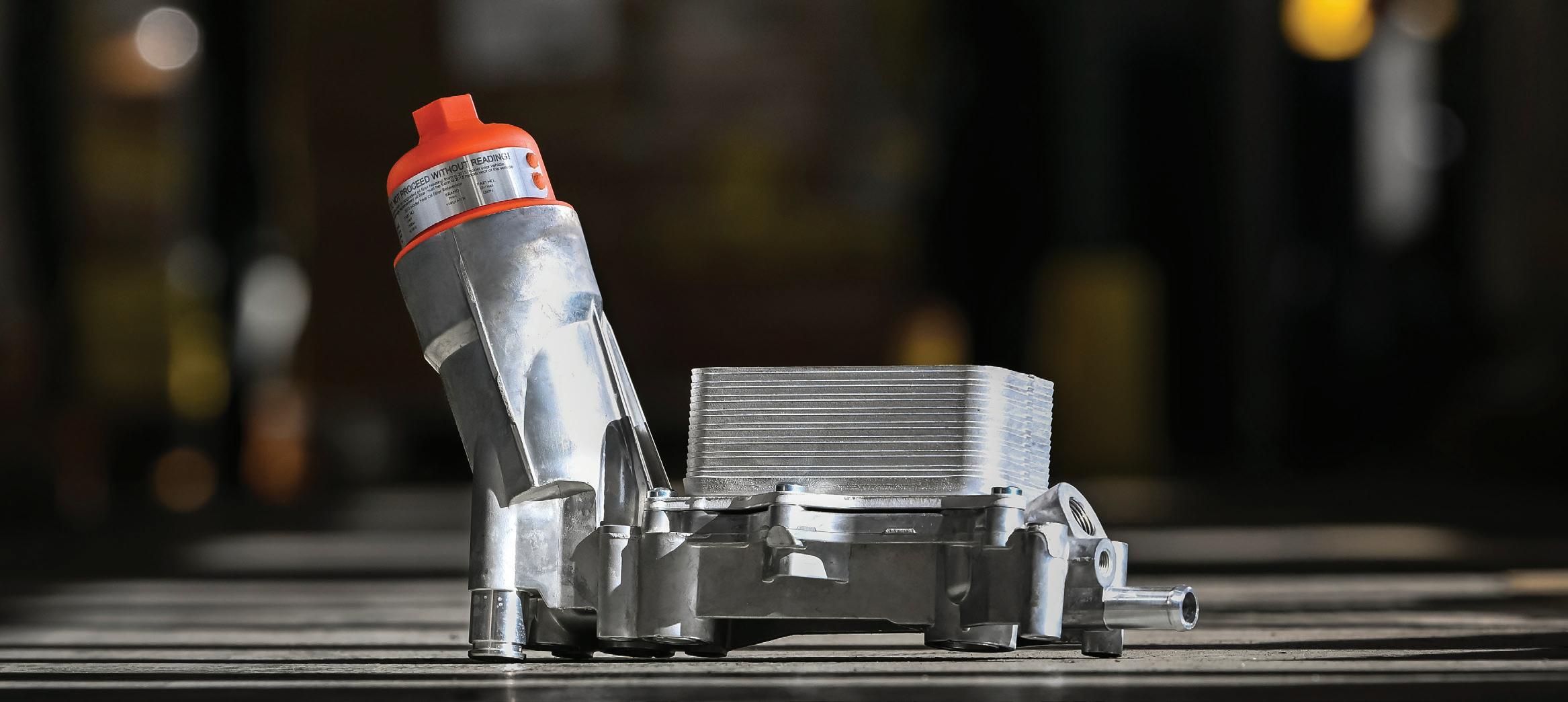
The oil filter adapter on millions of Chrysler, Dodge, Jeep and Ram V6-powered vehicles often leaks oil when its plastic housing warps from harsh underhood conditions. As the plastic eventually degrades from heat and chemical exposure, it can even crack from simply tightening the oil filter cap during oil changes. When it fails, replacing it with an OEM housing could mean the same issues again in the future.
This patented Dorman OE FIX filter housing is made entirely of aluminum for a more durable replacement of the failure-prone OEM housing to help prevent future leaks. The housing comes complete with mounting and intake manifold gaskets for an effective repair. The kit also includes the oil cooler, oil filter element, and oil filter cap to update the vehicle to the latest design.


Patented design - features high-pressure, die-cast aluminum housing construction to more reliably replace the failure-prone plastic housing on specific 2011 and later Chrysler, Dodge, Jeep and Ram vehicles with Pentastar engines
Smarter solution - includes required gaskets, oil cooler, oil filter element and cap, bringing early fitments to latest generation filter specification; see included instructions on filter cap
Trustworthy quality - engineered in the United States and made with durable materials to precise specifications, including premium seals to further help resist future leaks


STARTERS
04 Online Extras
Straight Talk
10 Learning With the Training Wheels On
Stepping outside of the comfort zone is uncomfortable for most technicians, especially with driveability. But doing so gradually softens the blow and boosts confidence and efficiency.
Brandon Steckler
16 Cracking the Code on Catalyst Efficiency
Understanding switch ratio vs. oxygen storage capacity
Erik Screeden
22 Proper Main and Rod Bearing Oil Clearance
It’s a critical aspect to engine assembly
Mike Mavrigian
32 Harnessing Heat
Understanding heat pump systems in EVs and hybrids
Jeff Taylor
43 The Bigger Picture
When you can’t see the forest for trees, you tend to miss a lot. My advice? Take a step back and see the bigger picture.
Brandon Steckler
46 Looking Back on 25 Years of EV Technology
The future is getting here quickly, and for many, EVs are a practical alternative to ICE-powered vehicles.
Craig Van Batenburg
66 The Trainer #163
Variable Reluctance Sensors
Brandon Steckler
for any loss or damage caused by errors or omissions in the material herein, regardless of whether such errors result from negligence, accident, or any other cause whatsoever. The views and opinions in the articles herein are not to be taken as official expressions of the publishers, unless so stated. The publishers do not warrant either expressly or by implication, the factual accuracy of the articles herein, nor do they so warrant any views or opinions by the authors of said articles.
Endeavor Business Media provides certain customer contact data (such as customers’ names, addresses, phone numbers, and e-mail addresses) to third parties who wish to promote relevant products, services, and other opportunities that may be of interest to you. If you do not want Endeavor Business Media to make your contact information available to third parties for marketing purposes, simply call toll-free 877382-9187 or email MotorAge@omeda.com and a customer service representative will assist you in removing your name from Endeavor Business Media’s lists. Motor Age does not verify any claims or other information appearing in any of the advertisements contained in the publication, and cannot take responsibility for any losses or other damages incurred by readers in reliance of such content. While every precaution is taken to ensure the accuracy of the ad index, its correctness cannot be guaranteed, and the publisher waives all responsibility for errors and omissions
ONLINE
TALK SHOP. ANYTIME.
150,000 AND COUNTING
The Motor Age YouTube channel hit a milestone in July by crossing the threshold of 150,000 subscribers. With nearly 800 videos and more than 16.6 million views, we think these subscribers are on to something! Don’t miss the handson, visual guidance our technical team has been providing to online viewers for the past 15 years. Go to the Motor Age YouTube channel and click that subscribe button!
TAKE OUR QUIZ
Did you know that in addition to reading and watching Motor Age’s technical content, you can also take a stab at solving some of the diagnostic mysteries our writers encounter? Each month when Technical Editor Brandon Steckler presents his Data Doesn’t Lie case study, you can now answer the final diagnostic question online. Look for the quiz at the bottom of those stories, and look for more quizzes to come.
EDITORIAL
GROUP EDITORIAL DIRECTOR
Chris Jones / christopherj@endeavorb2b.com
EDITOR
Mike Mavrigian / mmavrigian@endeavorb2b.com
MANAGING EDITOR
Joy Kopcha / jkopcha@endeavorb2b.com
TECHNICAL AND MULTIMEDIA CONTENT DIRECTOR
Erik Screeden / escreeden@endeavorb2b.com
TECHNICAL EDITOR
Brandon Steckler / bsteckler@endeavorb2b.com
ASSOCIATE EDITOR
Madison (Gehring) Hartline / mgehring@endeavorb2b.com
CONTRIBUTING WRITERS
Jeff Taylor, Craig Van Batenburg
ART AND PRODUCTION
ART DIRECTOR
Emme Osmonson
PRODUCTION MANAGER
Mariah Straub
AD SERVICES MANAGER
Karen Runion
SALES
ASSOCIATE SALES DIRECTOR
Mattie Gorman-Greuel / mgorman@endeavorb2b.com
DIRECTOR OF BUSINESS DEVELOPMENT
Cortni Jones / cjones@endeavorb2b.com
ACCOUNT EXECUTIVES
Kyle Shaw / kshaw@endeavorb2b.com
Marianne Dyal / mdyal@endeavorb2b.com
Annette Planey / aplaney@endeavorb2b.com
Darrell Bruggink / dbruggink@endeavorb2b.com
Sean Thornton / sthornton@endeavorb2b.com
Diane Braden / dbraden@endeavorb2b.com
Lisa Mend / lmend@endeavorb2b.com
Chad Hjellming / chjellming@endeavorb2b.com
ENDEAVOR BUSINESS MEDIA, LLC
CEO Chris Ferrell
COO
Patrick Rains
CRO
Paul Andrews
CDO
Jacquie Niemiec
CALO
Tracy Kane
CMO
Amanda Landsaw
EVP VEHICLE SERVICE/REPAIR GROUP
AND FLEET AND TRAILER GROUP
Chris Messer
BUSINESS STAFF
PUBLISHER
Andrew Johnson
BUSINESS DEVELOPMENT DIRECTOR, MOTOR AGE TRAINING
Michael Willins
CUSTOMER MARKETING MANAGER
Leslie Brown
AUDIENCE DEVELOPMENT MANAGER
Tracy Skallman
SALES COORDINATOR
Jillene Williams
HOW TO REACH US
ENDEAVOR BUSINESS MEDIA LLC.
30 Burton Hills Blvd, Ste. 185, Nashville, TN 37215
Phone: 800-547-7377
CUSTOMER SERVICE
Subscription Customer Service 877-382-9187; 847-559-7598

SUBSCRIBE

MotorAge@omeda.com PO Box 3257 Northbrook, IL 60065-3257
REPRINT SERVICES reprints@endeavorb2b.com
MEMBER OF:


Engine Replacement
What approach is best?
IF A CUSTOMER’S ENGINE has seen better days and needs to be rebuilt or replaced, you have several options. Which option is best? That depends largely on availability and cost. Depending on current engine condition and year/make/model, choices may include rebuilding the engine inhouse, having the engine rebuilt by a local engine machine shop, buying a reclaimed (i.e. salvage yard) engine, buying a new replacement engine from the automaker or buying a remanufactured engine from an independent remanufacturer.
Depending on the specific engine and its current condition, you may opt to perform a rebuild in-house. Of course, this depends on having a tech who is comfortable with this task. In addition, once the engine is torn down, it’s important to verify the condition of key components — block, crankshaft, connecting rods, cylinder heads. This may dictate the need for block deck resurfacing, cylinder over-boring/ honing, cylinder head reconditioning, condition of crankshaft main and rod journals, condition of the connecting rods, etc.
If machine work is needed, since your shop may not be equipped with the necessary equipment, you may need to farm this work out to a local engine shop. Once all machine work has been done, one of your techs may/should be able to reassemble and install the crank, bearings, pistons and rods, cam(s), heads, timing system, oil pump, intake manifold, etc. This approach will take some time, especially considering the local engine machine shop’s lead time. If the customer is comfortable with a potentially long timeframe (which could easily involve as much as a month or so, depending on various factors), this may be a viable option.
Another option is to turn the engine over to a local engine shop and let them handle the entire task (engine disassembly,
cleaning, inspection, reconditioning, and assembly). Once the engine is done, your shop performs the installation to the vehicle. Again, this can result in a lengthy time period, as most of today’s quality engine machine shops/engine builders seem to be slammed with work, so don’t be surprised if you face a lengthy delay.
Buying a used engine from a salvage yard is sometimes viable but this comes with a degree of risk. Depending on circumstance, maybe all you really need is a good shortblock, if you plan to re-use the existing heads, intake, water pump, etc. Or maybe you need a longblock (shortblock with heads). In either case, the condition of the engine is obviously critical. You certainly don’t want to waste your customer’s money and your reputation by installing an engine that is plagued with problems. Low-mileage used engines may seem attractive at first glance, but this is dependent on how the engine was maintained by the previous owner (maybe they never changed the oil). Unless you can obtain a limited “warranty” from the salvage yard as to the engine condition, it’s up to you to pull the heads and the oil pan to perform a cursory inspection. Costwise, buying a salvage engine may be the most attractive price option in the eyes of the vehicle owner, but it’s up to you to make sure that the used engine will be reliable. Depending on the year of the vehicle, a fresh shortblock or longblock may be available from a local automaker’s dealership. This may, again, depending on the automaker, involve a brand new engine or a factory rebuilt engine. I hate to keep using the phrase “depending on,” but there are variables. A “new” engine (short or long block) will likely be a tad on the expensive side, but depending on stock availability, you may be able to obtain the engine in a matter of a few days. A factory reman engine should include a reasonable warranty.
An option to consider is to purchase a remanufactured engine from a reputable engine remanufacturer. Notice that we’re not referring to “rebuilt,” which might involve only a cleanup and replacing a few parts and/or minimal machining. A quality remanufactured engine will provide a product that has been 100% inspected and reconditioned, correcting any issues that retired the original core. As long as an established and reputable remanufacturer does the work, the final product may actually be better than when the engine was when newly made, as any slightly out-of-tolerance issues will likely be corrected. A quality remanufacturer usually provides a limited warranty — maybe one year and 10,000 miles. (This is only an example.)
When a customer has an issue that can’t be solved by parts replacement alone and requires a freshening-up or total replacement, you have choices. No engine replacement will be cheap, but in addition to cost, the vehicle downtime is a major consideration. Obtaining a ready-to-go reman engine is often the best bet.


MIKE MAVRIGIAN MOTOR AGE // EDITOR mmavrigian@endeavorb2b.com


F-150 No Crank
Beware that some 2021-2023 Ford F-150 vehicles may exhibit a no-crank/ no-start condition accompanied by excess battery draw and the A/C clutch engaged at all times. This may be due to an open diode in the A/C clutch field coil, damaging the output driver (field effect transistor/FET) in the body control module (BCM).
Install a battery charger and fully charge the 12V battery. Turn the ignition off, exit the vehicle and shut all doors to allow the vehicle to go into sleep mode for about 15 minutes. Then check for voltage on circuit CH401 (VTWH wires) pin 1 at the A/C compressor clutch connector C100. If voltage is present, disconnect the battery and replace both the BCM and the A/C clutch field coil assembly.
Loud Bang
When Braking
If the owner of a pickup truck complains of a loud bang when stabbing the brakes hard, before you delve into inspecting the chassis or the ABS, check to see if the under-bed spare tire/wheel assembly is properly tightened down. A loose spare may be causing the sudden, loud “bang” noise that at first appears to be coming from the rear axle.
Kill the Stink
An easy way to remove unwanted odors from vehicle interiors is with the use of a portable ozone machine. Ozone is a naturally occurring gas in the atmosphere. These plug-in household-current units generate ozone gas (O3) to eliminate odors and help sanitize the interior, eliminating odors caused by smoke, mold, and other smells. Ozone generation purifies the air and surfaces of the interior without causing any harm to metals, plastics, leather, or fabrics. Place the unit in a
central location as high as practical (on the dash, on a center armrest, etc.) Roll all windows up, leaving one window down about two inches or so. (This provides a bit of air exchange as well as a path for the unit’s power cord.) Allow the unit to run for a required time, perhaps 30 minutes. If the unwanted odor remains, perform a second operation. Note: after running the ozone generator, you may notice a slight “copper/ metallic” taste in the air. This is normal and will subside quickly.
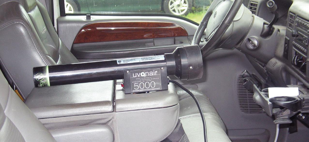

EXAMPLE OF AN OZONE generator in a vehicle interior.
EXAMPLE
Fill the Filter
This is basic information but is sometimes ignored. When performing an engine oil change, always pre-fill the oil filter before installing. Of course, this is dependent on the application. If the filter is installed horizontally or upside-down, this will not be practical, as you’ll spill much of the oil during filter installation. The goal is to add oil to the new filter whenever possible. This allows a faster and more efficient delivery of oil to the bearings. Granted, it will likely take only a few seconds for the system to fully charge, but pre-filling the new filter provides a bit of added protection. Also, before disposing of the old filter, if time permits, it’s a good idea to cut the old filter apart and examine the filter pleats for debris, which will provide an indication of bearing wear/damage. Granted, pre-oiling the filter is not absolutely necessary. After draining oil from the sump, a film of oil remains clinging to vital components such as main and rod bearings. Regardless, pre-filling the new filter remains a good idea. It might not be a deal breaker, but it can’t hurt.
Don’t Hand
Grind the Decks
Before installing original cylinder heads onto the original engine block, it should be obvious that both deck surfaces must be thoroughly clean. However, don’t be tempted to use a handheld grinder or drill equipped with an abrasive disc. This can easily ruin the Ra finish that is so crucial for proper head gasket sealing, and performing the task using a hand-held power tool can also easily create surface waviness that will hinder or ruin the gasket’s ability to seal. Also, avoid using Scotchbrite pads or discs on an assembled short block, as the microfibers that are released can contaminate the oiling system. Using a fast-evaporating solvent and a plastic scraper is a much safer plan.


Learning With the Training Wheels On
Stepping outside of the comfort zone is uncomfortable for most technicians, especially with driveability. But doing so gradually softens the blow and boosts confidence and efficiency.
BY BRANDON STECKLER // Technical Editor
LIKE MANY OF YOU, I began my path towards being a driveability technician learning basic tests that have been around for decades. These tests worked well but the issue I find with these triedand-true tests is that they are becoming
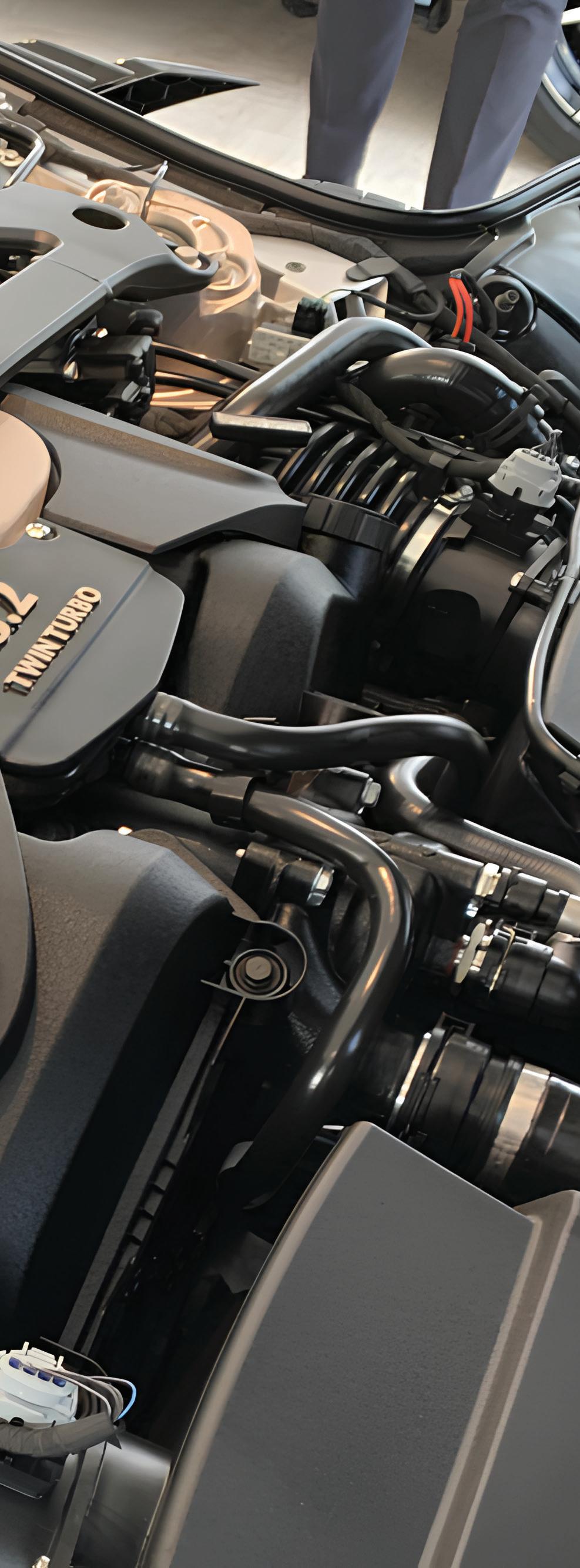
more and more difficult to implement with today’s powertrain configurations. For example, look under the hood of nearly any vehicle using an internal combustion engine and simply imagine removing the spark plugs to perform a
compression test. You’d be hard-pressed to complete that task easily, or in an efficient manner (Figure 1). Component accessibility is not as it used to be and with that, if you want to stay on the forefront of efficiency, your diagnostic tools and testing strategies must adapt as well. The question becomes, “What are you waiting for?”
Engine Failures Like Never Before
But I know what many of you are thinking. And the answer to the question above is typically derived from two different camps.
• “I don’t need that new stuff; my compression gauge hasn’t let me down in 30 years.”
• “I’m not sure how to use those fancy tools. I’m just not good with that sort of stuff.”
Well, I have a valid answer to both because I can speak from experience with each! Let me first state that engines are not nearly as robust as they once were. Sometimes the slightest overheating condition can wreak havoc on an engine — so much so that the entire assembly requires replacement. And the reason makes total sense.
With stringencies of today’s emissions standards on the rise, manufacturers have been forced to drastically increase fuel economy and engine performance output, but at the same time must reduce tailpipe emissions. (This includes carbon dioxide production, typically viewed as an indicator gas for efficiency, a desirable gas; it’s now viewed as a greenhouse gas that contributes to global warming.)
The real kicker is all of this must be derived from smaller power plants. This is the reason we’ve seen many vehicles typically equipped with 8-cylinder platforms drop two of the cylinders.
With all the performance technologies combined this is possible but it requires the engines to be pushed to the brink of destruction. Manufactur-
ers extract every bit of power output from them as possible. At the same time, these engines have become very sensitive, and as a result I have seen more engine-mechanical failures in the last five years than I have in the previous 23 years combined!
So why did I get away from traditional testing, like the mechanical gauge compression test? For one, as mentioned above, accessibility is becoming more of a premium. But more to the point, the compression test only shows a cylinder’s ability to harness and squeeze what’s inside it.
I mention this point because most of the engine failures I see today are with the valvetrain. A simple collapsed intake valve lifter or one that was wiped out with a disintegrating cam lobe drastically reduces valve duration and directly affects the cylinder charge (Figure 2). Even with a perfectly sealed cylinder, compression could be far below specification. The traditional compression test will show you “low-compression” but won’t tell you why. To know more requires disassembly and inspection. Many times, this is an expensive gamble, especially on today’s powertrains.
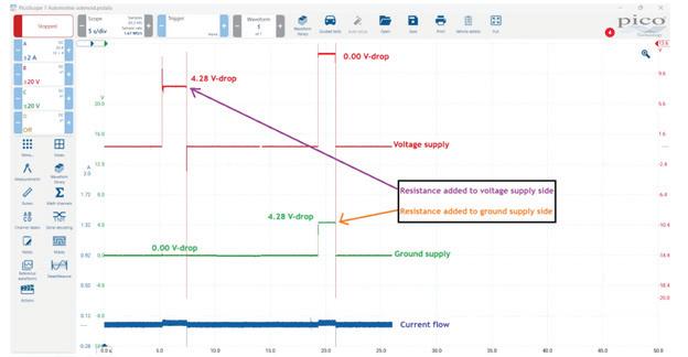
Advanced Electrical/Electronic Systems
Electricity has been present in automobiles since their inception. For decades, technicians relied on simple devices like test lights and digital volt/ohm meters (DVOMs) to prove out circuit integrity. And, although both of these devices function well, they indeed have limitations (Figure 3)
In years past, the electronics were limited compared to what is found in today’s vehicles. Simple circuits that carried a lot of current (like power window switches) were designed to be in series with the motor itself. This means the entire circuit saw the same current flow as the motor windings. Basic tools like test lights were all that we needed to determine circuit integrity as almost
FIG. 1: It’s engine bay configurations like this Aston Martin V12 that make the tried-and-true tests like the compression test (with a mechanical gauge) a tough pill to swallow. These tests, intended to be easy, could take hours to perform.
PHOTO BY AUTHOR
any change would yield a different brilliance (or none, at all) from the test light, making faults easy to detect.
However, these simple circuits have been replaced with electronic control. Of course, there is still a requirement for the high current flow, but it’s limited to the motor circuit itself — not the switched circuits providing the window request. These switched inputs may be messages from a communication network. These circuits carry minimal current (certainly not enough to illuminate a test light). And it’s the width of the pulses (in different combinations) that determines the message being delivered. Not even a voltmeter could demonstrate that well. Diagnosis is limited to the robustness of the scan tool software, the technician’s understanding of the communication network protocol and most often, a thorough process of elimination, dedicating a lot of time to disassembly.
Pushing Your Boundaries
Above were just a few examples to make my point. Of course, there are many more. But to demonstrate an approach to help you step outside of your comfort zone, I would like you to imagine yourself in my shoes. I do not want you to drop your routine like a bad habit. If you are an experienced diagnostician and you are seeing success and accuracy in your diagnoses, wonderful! Keep doing it!

To broaden your horizons, you are going to have to reach farther than you have before. This can be an almost painless process if you set yourself up for success. My goal for you is to be confident in your venture, and to do so means to have a plan.
Step #1: Begin implementing the tests you are learning on known-good vehicles. My recommendation is to schedule some time each week to stay late after work. Prove to yourself that you can set up and capture the correct data for whichever new test/tool you are implementing. Of course, the data should reflect a healthy functioning component or system (Figure 4)
I make this suggestion because otherwise, when you have hiccups — of course, there will be hiccups along the way, but that is part of the learning process — you’ll surely struggle to distinguish between a true fault of the vehicle and an oversight in the testing process being implemented. If you can do that, you are ready to take the next step.
Step #2: Now it’s time to approach a broken vehicle. What I am requesting you do is add some more work for yourself. Yes, that’s right, do the “new test” (in this case, the relative compression

test). But what I’d like for you to do is simply capture the relative compression data as best you can. Save the scope data captured and do not rely on it as input for diagnosis. Continue to rely on the mechanical gauge compression test because you trust it and it has served you well. When you have a diagnosis present it to your customer (however that occurs in your shop) and assuming the approval for repair is offered, complete the job.
Step #3: Now, when the repair is complete, and before delivering the vehicle to the customer, repeat the relative compression test and again, save the scope data. When the dust settles and the workday is over, take the time to review the pre- and post-repair files for analysis. When success occurs, you will know it because you will recognize the fault in the capture, and it will correlate directly with the tried-and-true mechanical gauge compression testing you have carried out.
Practice Makes Perfect
Let’s try another example. Go back to an intermittent “no-communication” issue, perhaps it’s due to a fault that won’t allow communication on the network. Nowadays, the scan tool software (at least at the OE level) is robust enough to offer some excellent preliminary data

you tools and testing techniques (on known-good vehicles) is not only crucial to growth but also fun! Here, I’m with a group of my mates in the UK, having a great time experimenting on an engine you will likely never see in the United States.
FIG. 2: A worn cam lobe or even a collapsed lifter can drastically affect compression yet yield absolutely no cylinder leakage. Traditional testing would leave inconclusive results.
PHOTO BY AUTHOR
FIG. 3: Simple electrical circuit testing tools like the incandescent test light worked well for decades because the same electrical current used to operate actuators would flow through the switched inputs governing the operation. However, the inputs are now sometimes network messages carrying virtually no current and at incredibly fast speed, far exceding the capabilities of tools like test lights and even DVOMs.
PHOTO BY AUTHOR
FIG. 4: Scheduling time to experiment with new-to-
PHOTO BY AUTHOR


A seamless, full-system solution that guides you from setup through calibration in half the time.
Professional Diagnostic Scan Tools
The next generation of scan tools with the most advanced OE-level vehicle coverage supporting scanning, live data access and complete bi-directional functions.


Heavy Duty Diagnostics
Down time for heavy duty vehicles can cost thousands of dollars. Our solutions help simplify navigating through complex coverage and sophisticated systems to perform ultra-fast and accurate diagnosis.

Tune and Analyze
Test, analyze and diagnose your vehicle electrical and mechanical systems.
to support communication network fault diagnosis. However, even the greatest software won’t come out and point to the faulty component.
With that, the name of the game is “divide and conquer.” In the case of the fault described above, a fault in the wire harness could cause the symptom. Although a process of elimination could eventually render a diagnosis, the potentially dozens of nodes on the network (strewn throughout the vehicle) could also be the cause.
Then again, an output that is controlled by the suspect-ECU could create electrical noise (creating feedback to that ECU) contaminating the entire network. This would make the node look faulty and would lead to unnecessary replacement. The outcome would be very disappointing and potentially expensive. I urge you again to do what you do. Follow the same steps as in the previous example. Before the vehicle is repaired, take the time to implement a new test.
Perhaps you recently attended some training, and learned to implement a lab scope to view CAN bus network activity. Take this time to monitor the network, before a repair attempt is made. Reproduce the fault and capture the CAN bus network activity with the lab scope.
Viewing the data and (for example) seeing that CAN_Hi and CAN_Low both exhibited some high-frequency noise, but only when the headlamps were on, was cause for concern but also led to a visual inspection.
The headlamp bulbs were LED but should’ve been HID. Using this data pointed the technician toward a wiring diagram that showed the body control module (BCM) as the device driving the headlamp circuits.
The transistors operated at a very high frequency because the BCM was not happy with the unexpectedly low current values of the headlamp circuits. This high-frequency switching induced noise on the network (Figure 5)
What’s the point? If not for the lab scope, the noise wouldn’t have been seen. The technician would likely have condemned the BCM for being faulty and would’ve replaced it unnecessarily. What’s more important is there was no need for disassembly, nor process of elimination. The data derived from the scope capture yielded no reason to condemn anything but the aftermarket headlamp bulbs. This never could have been determined with certainty without the scope testing. In fact, it’s unlikely that any tech would’ve found this root

cause fault in any reasonable amount of time, or without many misdiagnoses along the way.
The Leap of Faith
I can promise you several things if you heed my advice. For one, you will feel a sense of frustration as these new and unfamiliar tests will leave you with many failed attempts. But Thomas Edison failed to make the light bulb properly 10,000 times before seeing success. Stick with it!
Secondly, there is a time and place for everything. Please don’t get yourselves into trouble by trying to “learn on the job.” Each one of our work bays is a business within a business. They must be profitable, and this can’t occur if we experiment on the clock. Schedule some time after hours (I suggest once per week) to experiment with knowngood vehicles.
And last, but certainly not least, learn to trust your test results like a pilot of a jet airliner trusts his or her gauges in the clouds. When you practice enough, a sense of confidence builds within you. You’ll certainly find that knowledge begets new knowledge and testing in the described fashion will make you a better, more knowledgeable technician, making you a very powerful diagnostic weapon.
In seemingly no time at all, you will put to rest the time-consuming tests you’ve relied on so heavily for so long. You will begin to replace those tests with the newer, more efficient and less invasive testing you’ve been practicing diligently to implement.
Just like learning to ride a bicycle with the training wheels on, it’s a process. But it’s one worth seeing through as it will serve you well for the remainder of your career. Make tomorrow a new day and take your career as a diagnostician in a very rewarding direction. Learning with the training wheels on is safe and gratifying — you’ll see.

FIG. 5: The high frequency fault seen here (caused by LED headlamp bulbs) could’ve never been seen with tools less capable than the lab scope. Learning to implement tools like this saves hours of diagnostics time, hours more of disassembly, and potentially thousands of dollars in unnecessary component replacement. PHOTO BY AUTHOR
Understanding switch ratio vs. oxygen storage capacity
BY ERIK SCREEDEN
Cracking the Code on Catalyst Efficiency

SPACING OUT rear O2 sensors with spark plug non-foulers has been used with varying effectiveness for years to try and desensitize the downstream sensors by moving them out of the direct exhaust flow. This practice is not only highly illegal but has been made mostly ineffective by some of the more advanced OSC testing procedures in newer vehicle models.
AGE TRAINING AND TST SEMINARS
PHOTO: MOTOR
WITH EVER-TIGHTENING EMISSIONS standards and a continuing increase in average vehicle age, accurate catalytic converter diagnostics are more important than ever. The modern three-way catalytic converter (TWC) is an oxygen storage device that plays a vital role in reducing harmful emissions such as hydrocarbons (HC), carbon monoxide (CO), and nitrogen oxides (NOx). These harmful tailpipe emissions are chemically converted into less harmful substances (nitrogen, carbon dioxide and water) by the catalytic converter,
but its ability to do so depends on that catalyst being in good condition, and the engine maintaining near stoichiometric air-fuel ratio.
How Onboard Diagnostics Track Catalyst Health
To meet emissions standards, OBD-II systems need to monitor the conversion efficiency of the catalyst. Once that efficiency drops below a certain threshold, the system needs to trigger the malfunction indicator lamp, or MIL, off the detected fault, typically the P0420 or P0430 diagnostic trouble code. While specific testing methodology varies greatly by manufacturer and even vehicle model (and needs to be referenced by the technician in service information before any diagnostics begin), there are two main high level strategies employed by vehicle manufacturers to determine catalyst efficiency that technicians need to understand. These are:
• Switch Ratio: Comparing the oxygen sensor cross counts between the upstream and downstream oxygen sensor.
• Oxygen Storage Capacity (OSC): This test is based around the converter’s ability to absorb and release oxygen during changes in air-fuel ratio.
Both of these methods have their advantages and disadvantages, and vehicle manufacturers will base their chosen method of monitoring efficiency based on a variety of factors, including sensor technology. And while more vehicle manufacturers have turned largely to OSC in recent years, it’s important for the technician to understand the two monitoring strategies and their implications for diagnostics and repair.
For a technician to understand how efficiency is tested, it’s vital to understand how a modern TWC functions. The TWC performs three main functions:
• Oxidize carbon monoxide (CO) into carbon dioxide (CO2)
• Oxidize unburned hydrocarbons (HC) into water (H2O) and CO2
• Reduce nitrogen oxides (NOx) into nitrogen (N2) and oxygen (O2)
To accomplish this, the catalytic converter substrate is coated with a washcoat. That washcoat is the carrier of catalyst materials and is used to evenly distribute the elements across the substrate. The washcoat consists of elements typically including platinum (Pt), palladium (Pd), and rhodium (Rh). Rhodium is used as a reduction catalyst, palladium as an oxidation catalyst, and platinum as both a reduction and an oxidation catalyst. The ability of the conversion process to efficiently take place relies on the engine operating at a stoichiometric air-fuel ratio, around 14.7:1 for gasoline engines. It is at this ratio that the right balance of oxygen occurs to support all three chemical reactions. One of the main functions of the TWC is its ability to store oxygen during lean conditions and then release that oxygen during rich conditions to keep the conversion process going, even when the engine AFR wavers slightly.
As the catalyst ages, factors like thermal degradation, contamination, or physical damage can limit the ability of the TWC to store oxygen and perform the needed chemical conversions. When this occurs, the PCM needs to be able to detect this loss, and that is where testing like switch ratio or OSC comes into play.
When it comes to monitoring catalyst efficiency, switch ratio is the oldest and most widely used form of catalyst efficiency monitoring. The process is simple in theory. For vehicles that use narrow-band-O2 sensor technology, the upstream sensors will sweep between approximately 100mv and 900mv in closed-loop operation as the ECM adjusts fueling strategy to keep the engine as near stoichiometric air/fuel ratio as possible. A healthy catalyst will ingest more oxygen when the air/fuel ratio is lean, and release it as the mixture fattens up, buffering those fluctuations,
and leaving consistent voltage feedback from the monitoring rear O2 sensor. The ratio of fluctuation or sweep of the upstream O2 sensor(s) compared to those post converter is your switch ratio. Simply put:
Switch Ratio = (Number of upstream sensor switches) / (Number of downstream sensor switches)
The steadier the downstream O2 sensor voltage output, the better that TWC is performing. Adversely, a downstream sensor that is mimicking the sweeps of the upstream sensor suggests a catalyst that is no longer working efficiently.
Implementation of testing and the conditions needed to run that test will vary from manufacturer to manufacturer and even model to model. But once the predetermined parameters are met, the ECM enters its test mode. When testing, it will begin to monitor the cross counts from the upstream sensors (if equipped with traditional narrow band O2 sensor technology) and compare it to the cross counts from the downstream sensor. If the vehicle utilizes wide range air fuel ratio (WRAF) sensor technology, then the ECM may simulate narrowband behavior by adding and subtracting fuel during the test mode and monitoring downstream O2 sensor response.
Oxygen Storage Capacity (OSC):
Precision Monitoring
We have looked at switch ratio, now let’s take a look at oxygen storage capacity or OSC. This is the point where many people get confused. Switch ratio testing does ultimately test the converter’s ability to store and release oxygen, or its oxygen storage capacity. But the testing strategy of the ECM taking control of the mixture to measure the time-to-capacity is known as OSC testing. The OSC test is a more precise method of looking at catalyst efficiency. As stated earlier, a core function of a healthy TWC is the ability for that converter to store and release oxygen. The
principle behind OSC testing is that a well-functioning TWC will delay changes at the downstream sensor during controlled air-fuel ratio changes. The ECM monitors how quickly the downstream sensor responds as it fluctuates the mixture, rich or lean. The longer the delay in shift of rear oxygen sensor voltage, in theory, the healthier the converter is because of its ability to store oxygen. A reduction in OSC of the catalyst will cause the downstream sensor to respond too quickly, which may trigger a catalyst efficiency DTC.
For a technician, the great benefit of understanding OSC testing is it can be implemented to gain a better understanding of catalyst health, even on systems that do not use it as a native testing strategy. OSC testing gives a comprehensive look into TWC health and performance because it is able to illustrate in graphical form how much oxygen, or “how big of a gulp” that converter can take. By driving the air/ fuel mixture rich, forcing the TWC to deplete its stores of oxygen, and then driving the air/fuel ratio lean and allowing it to fill its lungs, that time base
between when the mixture was driven lean and when the downstream O2 sensor shows a reduction in voltage is a graphical indication of that catalyst’s ability to store oxygen.
OEM implementation of OSC testing as a monitor of catalyst efficiency has slowly grown in favor since the early 2010s. More and more manufacturers, such as Honda, Toyota, BMW, Volkswagen (VAG), Hyundai/Kia, and GM, have come to implement this testing strategy. Newer vehicles with faster and more powerful controllers, and the growing implementation of wide-band air fuel ratio sensor technology, allow manufacturers to emphasize precision and early fault detection. OSC catalyst monitoring also helps keep vehicle owners honest. With a little research, one can quickly learn how to space out the rear sensor and often hide a degraded TWC in a vehicle that uses less precise methods to monitor efficiency. OSC monitoring makes attempting to cheat an emissions test much more difficult.
What Happens When a Test Fails?
With either switch ratio or OSC testing, A SCREENSHOT of graphical O2 sensor voltage data on B1S1 and B1S2 taken from our Launch Throttle V on a 2013 Silverado with just under 100,000 miles. Under varying loads over the course of one minute you can see the switching frequency of the B1S1 voltage as compared to B2S2. While voltage from the downstream sensor will fluctuate a bit, a TWC with good oxygen storage capacity like shown here will not fluctuate with near the frequency nor amplitude like that of the upstream sensor.

PHOTO BY AUTHOR
if a test fails to meet programmed limits the ECM will do the following:
• Store a related DTC, often a P0420 (Bank 1) or a P0430 (Bank 2)
• Turn on the service engine soon light
• Log freeze frame data for the technician to use in diagnosing the problem Often a reduction of conversion efficiency of approximately 50% compared to a new catalyst is enough to trigger the aforementioned series of events. Catalyst monitoring is a non-continuous test, so unlike fuel trim or misfire detections which run continuously, catalyst monitoring only happens under certain operating conditions. These criteria are found in service information, and vary by manufacturer, but often include parameters like:
• Engine is up to operating temperature
• Vehicle is in closed-loop operation
• Idle or stable cruise (depending on test specifications)
• No active trouble codes for things like fuel trim, O2 sensors, or misfires
• Minimum drive time since last test If the criteria are not met, the test will not run. This is why referencing service information is vital for a tech -
nician to verify that a repair is paramount for customer satisfaction. These criteria are strict to ensure that the data gathered is accurate and not influenced by transient operating conditions. Often the test method chosen by vehicle manufacturers depends on fueling control strategy and sensor configuration. This means a technician is far more likely to find a vehicle that uses narrowband sensors to employ switch ratio testing, and one that uses WRAF sensor technology for at least the upstream sensor to employ OSC testing. Some manufacturers, such as GM, have even started implementing a hybrid approach to catalyst efficiency monitoring. These systems will often start with a switch ratio evaluation and then confirm with OSC. This approach of dual testing can help enhance the reliability of the onboard monitoring system and reduce the likelihood of false positive results.
Avoid the Guesswork: Diagnose With Precision
When it comes to chasing down catalyst efficiency problems, this is not the time

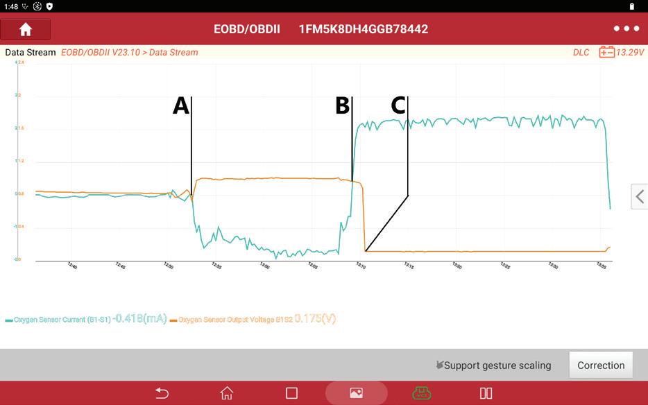
and test driving the vehicle we can illustrate this fact. Point A is where we put the vehicle in power enrichment by going to WOT. Between points A and B the vehicle is at WOT and the TWC has used up its stores of oxygen. Point B is when we close the throttle and put the vehicle in deceleration, fuel cut-off driving the mixture lean and allowing the TWC to “fill its lungs.” Point C is where the TWC reaches its saturation point and the O2 “punches through” the converter. Notice the time base at the bottom of the capture. The O2 punches through in under a second, illustrating poor oxygen storage capacity by this TWC, which is not surprising considering this vehicle has over 200,000 miles.
PHOTO BY AUTHOR
that a technician wants to start throwing parts at a vehicle in hopes that tossing that 50/50 ball yields a positive result. As I often tell my kids, it’s the painful and expensive lessons that tend to stick with you the most. Get me in a sports book in Vegas, and I’ll throw down on a juicy parlay, but I don’t want to gamble when it comes to repairs on a customer’s vehicle, especially with something as expensive as a direct fit catalytic converter assembly. There are many different things that can cause a catalyst efficiency DTC, and often the industry is quick to condemn a converter at the first sign of a P0420 or P0430 DTC without figuring out if the failure is indeed related to a degraded, poisoned or otherwise damaged catalyst. And, if that is the diagnosis, what exactly took the TWC out?
Now remember, a P0420 or P0430 does not always mean the catalyst is at fault. A vehicle has a fairly wide operating range while still being considered in fuel control. The TWC, on the other hand, has a very narrow air/fuel range it can operate within while still being effective. Because of this, a vehicle operating outside of that Lambda range of
EXAMPLE comes from a 2016 2.3L turbo Explorer and our Launch Throttle V. Again, A was the vehicle entering WOT (note the inverse graph due to mapping the sensor current for the upstream and traditional O2 voltage downstream), A to B is WOT operation with the TWC depleting its stores of O2. At B the vehicle again enters deceleration fuel cut-off, and point C is where the TWC is saturated and O2 is able to “punch through.” While this vehicle also has more than 100,000 miles, its ability to store oxygen is measurably higher than that of the previous Envoy. Different years, makes, and models will obviously have different storage capacities in the TWC, but testing like this offers a technician a good general idea in graphical form the condition of the TWC.
PHOTO BY AUTHOR
THIS IS a good example of a degraded oxygen storage capacity of the TWC. By graphing B1S1 and B1S2 O2 voltage on our Launch Throttle V
THIS
0.995 – 1.005 can trigger a catalyst efficiency DTC. Exhaust leaks caused by things like broken manifold bolts or a broken flex pipe upstream of the TWC, or even something like a split resonator, can cause problems if close enough (generally within 15 or so inches) to the downstream sensor.
Even if you do find the converter at fault, typically, something contributed to its demise. Poisoning from coolant and heavy oil deposits can degrade the life of a TWC significantly. And though rare anymore, lead and ZDDP poisoning are still possibilities as well. Prolonged and significant over

PHOTO BY AUTHOR
fueling can cause the converter’s ceramic substrate to start to plug, and even heat shielding that has corroded away can cause the catalyst to not maintain the correct operating temperature. Shotgunning a converter on a vehicle without performing root cause diagnostics is just inviting a comeback.
Smart Strategy = Successful Repair
Regardless of testing type, it is imperative that a technician trying to diagnose a catalyst efficiency problem research service information to determine which system they are working on, and the conditions needed to set the DTC they are chasing down to help set up their diagnostic approach. If the vehicle uses a switch ratio strategy, the technician then knows to focus on things like sensor switching activity (for narrowband O2 sensors) and O2 sensor waveform analysis (upstream versus downstream) to get a good picture of that switch ratio. For OSC, look at things like fuel trim behavior, upstream WRAF accuracy (sensor drift), and rear sensor response time. Catalyst efficiency diagnostics demand more than a surface-level understanding of DTCs and sensor data. As we’ve seen, both switch ratio and oxygen storage capacity testing have distinct applications depending on sensor technology and manufacturer strategy. The key takeaway for any technician is this: don’t guess. Proper diagnosis requires an understanding of how the system is designed to work, what conditions must be met for testing to occur, and how to interpret the results accurately. Whether it’s a failing sensor, an air/fuel imbalance, or a truly degraded converter, identifying the root cause is essential to avoid unnecessary repairs and costly comebacks. With the right knowledge and approach, technicians can not only fix the problem but also prevent it from happening again.
MODE $06 can be a valuable resource for technicians that is often underutilized. Found on the Global OBDII side of the tool, it offers the user a glimpse of diagnostic testing thresholds set by the manufacturer, and more importantly, how well the system is performing in that test. Some tools display this data as hexadecimal units (as seen here from our Throttle V) but that can be easily converted. This allows the technician to not only see system health but also help with after repair verification.
WHILE NOT containing any moving parts, the modern TWC is an important and complex piece of a vehicle ’s emissions control system. In order to perform its role optimally, it relies on multiple other systems in the vehicle to be intact and operating efficiently and correctly.
PHOTO: CLOUD-WALKER / SHUTTERSTOCK
Exhaust gases


PROPER MAIN AND ROD BEARING OIL CLEARANCE
It’s a critical aspect to engine assembly
BY MIKE MAVRIGIAN

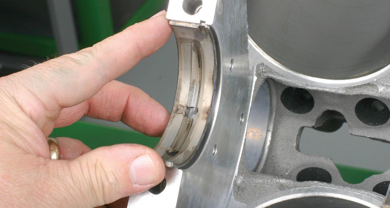
WITH MAIN bearings and main caps fully installed, the bore gauge is used to measure installed bearing inside diameter. The difference in the reading indicates oil clearance. Take the reading at 12 and 6 o’clock positions. Do not measure near/at the parting line.
PHOTO BY AUTHOR
THE IMPORTANCE OF OBTAINING proper oil clearance between bearings and rotating main and rod journal surfaces cannot be over-emphasized. Insufficient oil clearance reduces or eliminates the crucial oil wedge that the journals need during operation and excessive clearance can reduce oil pressure and can cause cavitation that creates aeration that can damage bearings. Crankshaft main and rod journals should never come into direct contact with their respective bearings. Rather, an oil wedge must be generated as the crank turns, allowing the journals to always ride on a supportive film of oil.
When checking for bearing oil clearance on main and rod bearing locations, do not blindly assume that “standard” replacement bearings will suffice. Due to potential stack-up tolerances between main bores, crankshaft journals and connecting rod big ends, do not blindly assume that “standard” thickness bearings will always suffice. Also the crankshaft journals may have been previously re-ground to recondition the crank (if the crank has been re-ground, the front face of the front counterweight should be stamped accordingly — i.e. 0.010, 0.020, etc., indicating journals have been ground to an undersize. If both main and rod journals have been reground, the first number should refer to main journals, with the second number referring to rod journals.)
Replacement bearings are offered in a range of thicknesses to allow the builder to achieve proper oil clearance. The crankshaft’s main and rod journals must be measured first, as these journals may or may not precisely meet the OE specifications.
In addition, the block’s main bore should be checked for size and alignment. If the engine has been rebuilt at some point, it is possible that the main caps have been ground to produce an out of round condition, followed by main bore align honing to return to the specified OE diameter. If the align honing process was performed poorly, you may have a main bore that is a tad too tight or too loose.
A potential stack-up of tolerances (main bore size and crank journal size) can easily result in inadequate oil clearance or excessive clearance. The same concern involves connecting rod big ends. Check rod big ends for out-of-round and for assembled diameter, especially if the rods have previously been resized. By merely assuming that main and rod bores and crank journals are correct, simply ob -
taining “standard” size bearings may lead to serious issues. Always measure first. In general terms, main bearing oil clearance should be 0.001-inch for every 1-inch of main journal diameter. For instance, if the main journals measure 2-inch in diameter, bearing oil clearance should be 0.002”. If main journals measure 2.749”, bearing clearance should be in the 0.00275” range. However, specific


AS CRANK rotation begins, the oil film is generated, creating a hydro-pressure ramp, which lifts the crank main journals into a concentric path. The same applies to the rod bearings, as the pressure of the oil film keeps the rod bearings from rubbing against the crank’s rod journals.
PHOTO BY MAHLE-CLEVITE
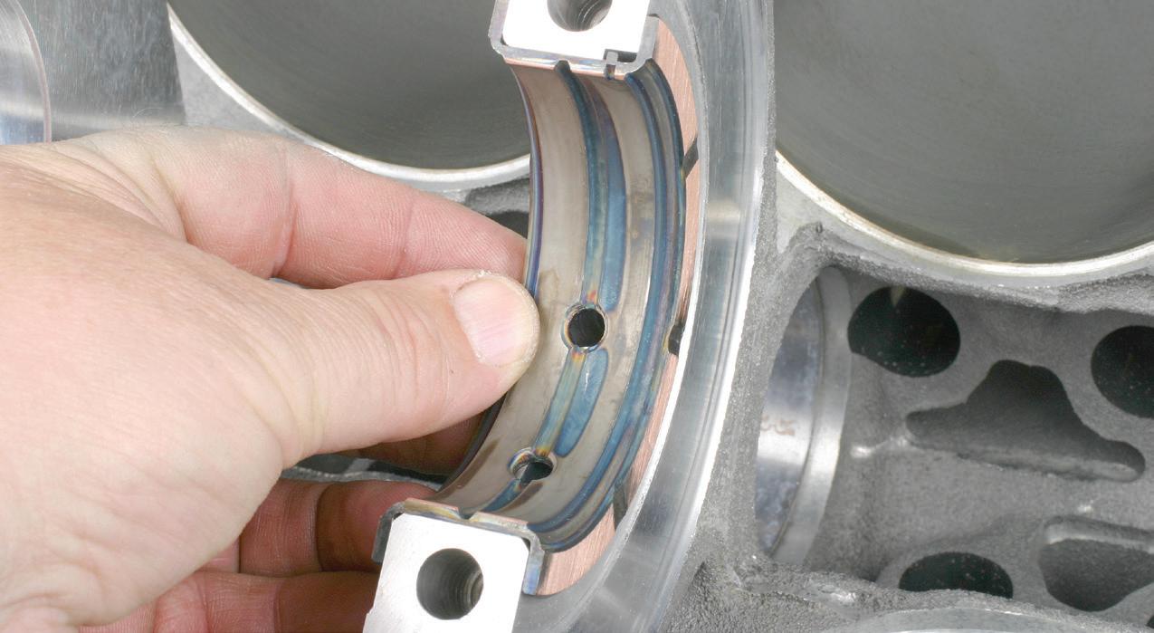
WITH THE cap installed, this exerts radial pressure, forcing the back (outside) of the bearing outward against its bore. Bearing crush is critical to hold the bearing in place and to create the proper bearing profile.
PHOTO BY MAHLE-CLEVITE
recommended clearances may vary depending on engine type and application. Engines intended for performance/racing use will typically require slightly greater oil clearance due to higher engine speed and load. Speaking in very general terms, a high performance engine’s main bearing clearance requirement might require an additional 0.0005” of clearance (for a 2” main journal, clearance would be approximately 0.0025”).
Again, depending on the engine application, main bearing oil clearance may vary from about 0.0017” to 0.0025”,
with the tighter clearance sometimes specified for many late model engine designs. Even though crankshaft rod journals are smaller than the mains, rod bearing oil clearance is generally in the 0.002” to 0.0025” range. It bears repeating: always refer to the specific engine maker’s specifications.
Keep in mind that today’s passenger vehicle engines typically run thinner viscosity oils and tighter tolerances.
In some cases, in order to achieve proper rod bearing oil clearance, upper and lower bearing shells of different thick-
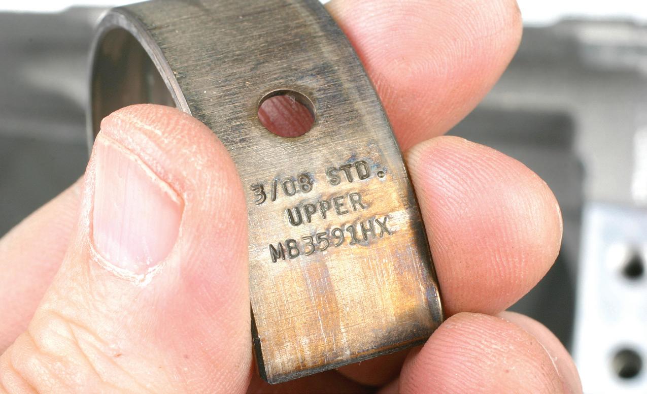
OF an upper bearing marked with a “1X”. This indicates that the bearing shell is thinner than standard. If both upper and lower bearing 1X shells are installed, this gains an additional 0.001” of oil clearance. If you only need an additional 0.0005” clearance, use a combination of a standard and a 1X.


ness may be paired. This is a common practice among performance or race engine builders. This allows you to “fine tune” oil clearance to gain or lose, for example, a 0.0005” clearance loss or gain (depending if the different thickness bearing set is for an oversized or undersized application). For instance, if your rod bearing clearance is 0.0020” but you want 0.0025”, in addition to a standard-size bearing set, you would purchase a set of 1X rod bearings. If you use the 1X bearings at upper and lower positions, you would gain 0.001” of clearance. But if you use a standard bearing at the lower (cap) location and a 1X bearing shell at the upper (rod saddle) location, you gain an additional 0.0005”. If rod bearing halves are mixed in order to achieve desired oil clearance, traditional school of thought is to install the thicker bearing half in the upper location, with the thinner half in the rod cap. Installing the thicker (for instance “standard”) in the upper location is better suited to handle the higher loading side. On the other hand, many builders feel that this is not necessary, as long as the orientation of thicker/ thinner bearing halves are installed consistently from rod to rod (for example, thicker upper and thinner lower on all rods, or thinner upper and thicker lower on all rods). Caution: Never mix bearings with more than 0.001” thickness difference.
CLOSELY INSPECT the bearing tang notches in the block saddles and main caps. Make sure that the notch is clean and free of burrs. Any debris/irregularities can affect oil clearance. PHOTO BY AUTHOR
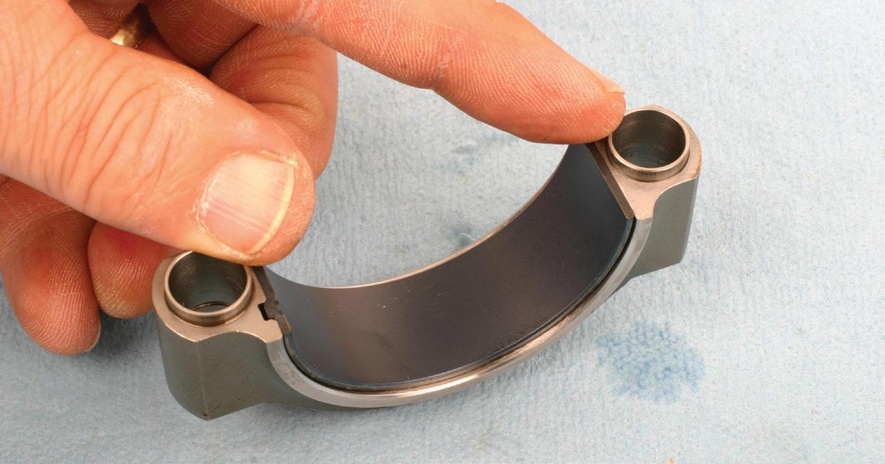
NOTE THE small tang on this main bearing. All main and rod bearings will feature a locating tang. This is designed to simply position the bearing in its saddle during assembly. Locating tangs do not prevent bearing shell rotation. Bearings “lock” in place as a result of bearing crush when the upper and lower shells mate during cap installation.
PHOTO BY AUTHOR
DEPENDING ON application, rod bearings may or may not be labeled for position, but be sure to check. Shown here is an upper rod bearing featuring standard thickness (note absence of marking 1X). Upper/ lower bearing inserts may feature slightly different profiles, so don’t mix them up.
PHOTO BY AUTHOR
EXAMPLE
PHOTO BY AUTHOR
When checking for bearing clearance, perform test fitting to confirm clearances prior to final assembly. Do not install the crankshaft at this time. For main bearings, install an upper main bearing shells in the block’s upper saddles. Make sure that the saddles are clean and dry. Install the upper bearings. Do not apply any lubrication to the bearings at this time. Install the lower bearings to the main caps and install the main caps. Tighten all main cap bolts to specification and follow the correct tightening sequence outlined in the service manual. Using a micrometer, measure the crankshaft main journal diameters. (Measure each main journal and record the results.)
Set up a bore gauge to match the crank journal size and zero the gauge. Then use the bore gauge to check the inside diameter of the installed main bearings. The difference observed on the gauge indicates the amount of clearance. Perform the check at the 12 o’clock and 6 o’clock bearing locations. Do not measure at or near the bearing parting lines. Bearing shells feature a slight taper approaching the parting lines, which aids in allowing the creation of the all-important hydrodynamic oil wedge required for supporting the journals to avoid direct bearing-to-journal contact.
Perform the same check on connecting rods. Install new bearings to the rod upper saddle and the rod cap. Install the rod cap and tighten the bolts to specification while the rod is clamped to a dedicated rod vise. Use a micrometer to measure the crankshaft’s rod journals and set up a bore gauge to that size and zero the gauge dial. Use the bore gauge to measure the installed rod bearings (again, at the 12 o’clock and 6 o’clock positions) and record the measurement. The difference between the measured rod journal and installed bearings indicates the amount of oil clearance. Once checks have been performed, place the rod in the rod vise and remove the rod cap.
Tighter oil clearance is generally
ALWAYS INSTALL main and rod bearings dry to the block, rods, and caps. There must be NO particles, oils, or anything else between the back of the bearing and its saddle. Lube is only applied to the exposed bearing faces prior to final assembly.
PHOTO BY AUTHOR
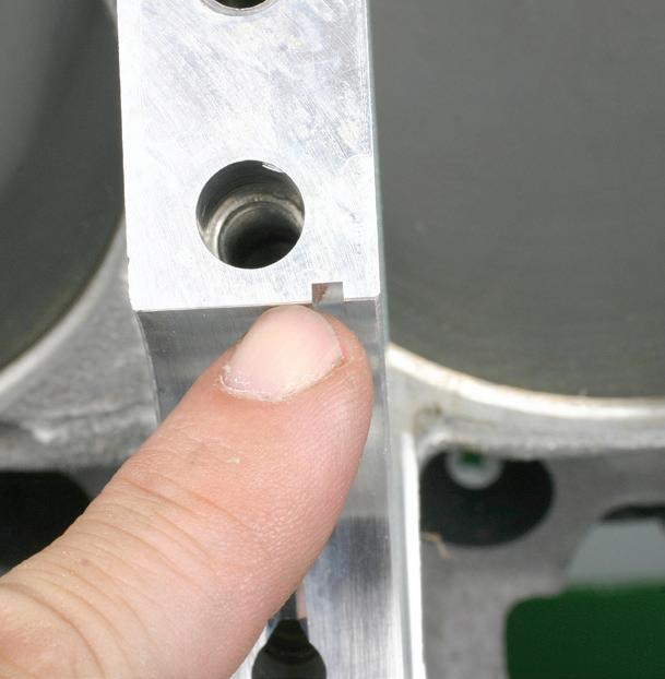
POSITION EACH main bearing in the block saddles with the bearing ends protruding by the same amount at each end, and verify that the oil holes in the bearings align with the oil feed holes in the saddles. If a slight misalignment is found, you can carefully elongate the hole in the bearing, being careful to remove any burrs.
PHOTO BY AUTHOR
INSTALL ROD bearings by aligning the bearing tang with the locating notch and press each end down with your fingers. Each end of the bearing shell should protrude by the same amount at each end.
PHOTO BY AUTHOR
required for small crankshaft journals, the use of lower viscosity oil, near-perfect crank and block geometry, higher engine operating temperatures and perfectly balanced crankshafts. Larger/looser oil clearances accommodate larger crank journals, higher viscosity oil, imperfect crank/block geometry, lower engine operating temperature due to increased oil flow, and weaker housing bores that have a tendency to slightly distort at high engine speeds.
In general, bearings should operate with the least amount of oil clearance as the application permits.
Tighter oil clearance produces less bearing peak loading, reducing the potential for less-than-smooth engine running. Again, pay attention to the engine maker’s clearance specs.
In order to measure individual bearing shell thickness, use a quality micrometer with a ball tip mandrel.
Never use micrometers with flatfaced anvils.


Before measuring, index the micrometer with a standard to insure accuracy and micrometer calibration.
Measure bearing thickness at the mid-point — at the radius, not near the parting line.
Always use the same micrometer for all measurements, as differences in calibration can affect accuracy.
When measuring installed bearing diameter, the rod bolts must be fully torqued to specification (and/or using rod bolt stretch method).
Maintain the same rod bolts per rod, and do not change bolt location.
Maintain the same brand of bearing. Never mix one brand with another.
Both upper and lower bearing halves must be from the same maker, and feature the same surface treatment. Do not mix coated with uncoated halves on the same rod.
Main and rod bearing clearance can be performed with the crankshaft in place, using Plastigage wire. This approach, while commonly used by non-professional
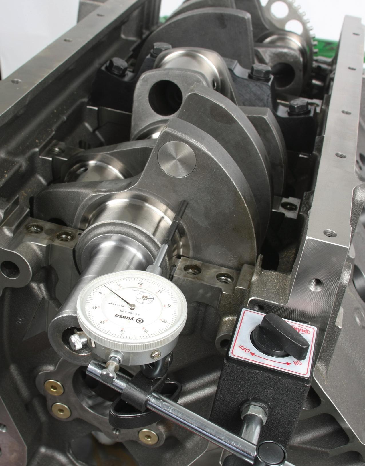

WITH THE crankshaft installed, check crankshaft end-play. Depending on engine design, thicker or thinner main thrust bearings may or may not be available. The thrust/endplay will be specified in the engine maker’s service manual. This may typically be in the range of 0.006 to 0.010”. Perform thrust check without and with main caps/ lower main bearings.
PHOTO BY AUTHOR
MEASURE CRANKSHAFT main journal with a micrometer. This example reads 2.749”. A bore gauge contacts are then adjusted to that journal diameter, and the bore gauge is adjusted to read zero.
PHOTO BY AUTHOR
EXAMPLE OF a bearing shell installed. The mating ends will slightly protrude above the saddle parting line, and each end should protrude by the same amount.
PHOTO BY AUTHOR
Supercharge Your Supply Chain With
Build Estimates In Seconds.
Wit h N expar t Mult i-S el ler you’re c onne cte d to real-t ime inventor y and whole sale pricing from al l o f your par ts suppl iers. Find par ts, t ires, and more Bui ld detai le d est imates fast!
Backe d by t he most c omprehensive catalo g in t he af termarket . You’l l se e more pro ducts, from more suppl iers, g iving you more c ontrol o f your supply chain.
earn points on every parts order Multi-Seller

ROD bearings to the connecting rod big end and tighten the rod bolts to specification with the big end secured in a dedicated rod vise.


SET A bore gauge to match the measured rod journal and zero the gauge reading. Measure installed rod bearing inside diameter. The difference indicates oil clearance.

ANTI-FRICTION COATING is always a good option for main and rod bearings. This coating not only promotes oil cling, but serves as an anti-friction protective layer in order to prevent bearing damage during cold starts and in brief instances of oil starvation. It is not necessary to have a moly coating applied to the front and rear faces of a main thrust bearing’s thrust surfaces, since it’s common for engine builders to sometimes fine-tune thrust clearance by filing a thrust face. An upper main thrust bearing shell is shown here.
engine builders, is a viable alternative but is much less accurate. Plastigage is a compressible plastic wire. Install the upper main bearings into the block’s saddles (dry). Place the crankshaft onto the upper bearings.
Lay a short piece of Plastigage onto the exposed journal, with the wire placed parallel to the crank (wire ends face front and rear). Simply lay the wire onto the journal — do not press down on the wire. Install a lower bearing to the main cap and apply a very light smear of oil to the center of the lower bearing (this prevents the crushed Plastigage from sticking to the lower bearing and pulling off of the journal). Install the main cap and tighten bolts to spec. Do not rotate the crank at any time during this check. Carefully remove the main cap. Using the Plastigage packing slip (which features a series of measuring width markings), compare the markings to the now-crushed Plastigage wire. The

APPLY OIL or assembly lube to the exposed bearing surfaces once bearings have been final-installed, just prior to engine assembly.
closest match indicates approximate oil clearance. Perform the same task with each installed connecting rod. Prior to each individual check, rotate the crank to place the rod journal at bottom-dead center. (With the block upside down, bring the rod journal up, closest to you, for easy access.) Record each clearance in an organized manner, and record your findings. Once done, clean the Plastigage from the journals. Your findings will dictate the use of standard bearings, or will indicate the need for slightly under- or over-sized bearings. Again, the use of Plastigage, while better than nothing, may provide an approximate measurement, but for highest accuracy, performing your measurements with a micrometer and bore gauge is always preferred.
Bearing Design Insight
A variety of bearing designs (and dimensions) have been developed to properly

BEARINGS are subjected to both rotational and reciprocal forces. Anti-friction coatings prevent potential bearing wear during cold startup and for potential intermittent poor oil delivery. Since the coating is of minimal thickness, no compensation is required in terms of installed bearing clearance.
you have discovered slight deviations where thinner/thicker bearings are required.
ROD
PHOTO BY AUTHOR
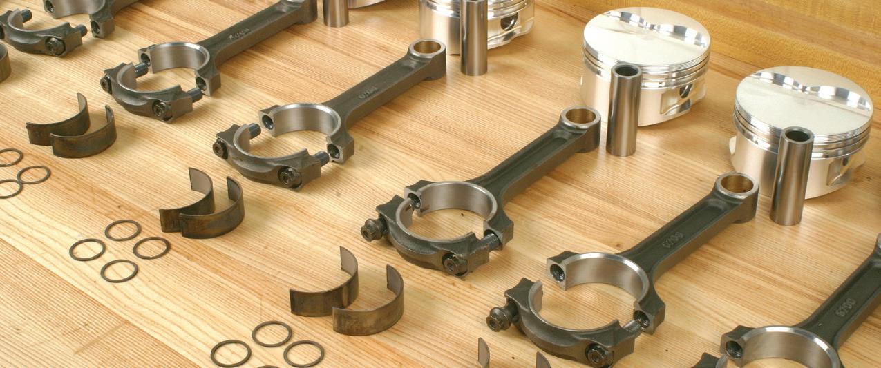
ONCE BEARING oil clearances have been checked and established, keep all bearings organized in their respective locations. This is especially important if
PHOTO BY AUTHOR
PHOTO BY AUTHOR
PHOTO BY AUTHOR
PHOTO BY AUTHOR
USING A micrometer, measure rod journal diameter.
PHOTO BY AUTHOR
INSTALL
PHOTO BY AUTHOR
THE HEART OF LONGER RUNNING VEHICLES
Continental heavy duty aftermarket air springs, belts, hoses, hydraulics, and tensioners keep your business operating in good health. Our precision-engineered parts are built to last and extend fleet life without skipping a beat. Continental, your first choice for premium aftermarket products.
RUN STRONGER , LONGER


suit any specific engine application. Before we delve into selecting and installing main and rod bearings, we first need to understand bearing design.
out-of-round in the horizontal plane or the vertical plane.


Main and rod bearings’ geometry provides an interference fit, or “crush.” Each bearing shell (upper and lower) is made with a length that results in slightly more than a true half-circle. The ends of the bearing shell, when installed into a housing, protrude slightly beyond the parting line of the housing. When the cap is installed and the cap bolts are tightened, these protruding ends of the bearing shells squeeze against each other and push the bearings against the housing, compressing together like a spring. The outward force of the bearings, as they squeeze into place, causes a slight change in the size and shape of the housing. This is referred to as bore distortion. As you might expect, different housing materials (such as steel vs. aluminum) provide different levels of bore distortion.

Many engine assemblers may not be aware that bore distortion may occur during assembly. Compensating for this bore distortion is the tricky part, since a multitude of variables can directly affect housing bore shape (main bores and connecting rod big ends).
One of the variables directly relates to the shape of the bearing housing mass. Blocks and rods feature irregular shapes that surround the housing bore. For example, connecting rods feature a beam at the top of the bore, notches for bolt heads and/or nuts at each side of the hosing bore, thin or thick ribs at the bottom of the cap, etc.
In addition, dynamic loads (when the engine runs at various speeds and loads) change in both magnitude and direction. All of these factors (design shape and reinforcement of the housing and dynamic loading) combine to cause the bearing housings to realize an out-of-round state under various operating conditions. Depending on the surrounding metal shape and mass, some housings will go
Bearings are not simply perfectly round liners that take up space between the housings and the crank journals. Bearing design is a very complex issue, a factor which most engine assemblers don’t fully appreciate.
Because of bore shape variables, the most desirable bearing shape is provided with a slightly oval bearing inside diameter. As a result, bearings are manufactured with an eccentric wall. In most cases, the bearing wall thickness is greatest at the top and bottom (90 degrees from the parting line). The bearing ID tapers slightly at the parting line area.
Connecting rods are especially subjected to high inertia loads at the top of the exhaust stroke, when the weight of the piston, rings, wrist pin and rod small end effectively pulls at the rod big end, in an attempt to stretch the rod. This dynamic force also tries to pull the rod big end out-of-round, which will cause the bearing housing bore to become tighter at the parting line area. In order to address this, a slight eccentricity is designed into the bearings, with the bearings thinner at the parting line area. This prevents the bearing from contacting the crank journal when bore distortion occurs.

MIKE MAVRIGIAN has written thousands of automotive technical magazine articles involving a variety of specialties, from engine building to wheel alignment, and has authored more than a dozen books that crisscross the automotive spectrum. Mike operates Birchwood Automotive, an Ohio shop that builds custom engines and performs vintage vehicle restorations. The shop also features a professional photo studio to document projects and to create images for articles and books.


Harnessing Heat
Understanding heat pump systems in EVs and hybrids
BY JEFF TAYLOR
WHILE OFTEN OVERLOOKED by consumers, heat pump systems have become one of the most influential technologies in modern EV and hybrid vehicles. They provide energy-efficient heating and cooling while preserving precious battery range.

As electric and hybrid vehicles increasingly replace traditional internal combustion engine (ICE) models, automakers have had to re-imagine nearly every vehicle system. One of the most critical challenges has been managing cabin heating, especially in cold climates where traditional methods either aren’t available or do not perform efficiently. In ICE vehicles, waste engine heat is plentiful and was used to heat the interior of the vehicle for years. In electric vehicles (EVs), however, that luxury does not exist. Many EVs and hybrid vehicles relied on Positive Temperature Coefficient (PTC) resistive heaters to provide the needed heat to the passenger compartment. But even with the simple, dependable fast warm up that the PTC heater provided; they are power-hungry devices that can significantly reduce EV range in cold weather.
Fortunately, most of these vehicles were already equipped with air conditioning systems and relied on an air conditioning compressor to provide cooling to the passenger cabin. This made it easier for manufacturers to transition to reversible heat pump designs, as they could build on existing components and infrastructure. The automotive heat pump system achieved both: a more efficient heating solution and the preservation of its full cooling capabilities.
In this article, we’ll examine what automotive heat pumps are, how they work, and examine some manufacturer highlights. We’ll also look at concerns technicians need to be aware of when diagnosing them, what problems have surfaced in real-world use, and how this technology is likely to evolve. By the end, you’ll understand why heat pumps are at the center of EV/hybrid thermal management and why mastering them is essential for today’s automotive professionals.
What Is a Heat Pump and Why Does It Matter in EVs and Hybrids?
Essentially, a heat pump is a thermodynamic system designed to move heat. It typically works by taking heat from a lower temperature source and releasing it at a higher temperature. In the case of EVs/hybrids, the system extracts heat from the ambient environment and delivers it to the cabin or to vehicle systems such as the battery pack. In warm weather, it can reverse its function, acting like a traditional air conditioning unit to cool the vehicle’s interior or remove heat from the high-voltage battery and other heat producing equipment.
The importance of this system in EVs/ hybrids cannot be overstated. Earlier EVs/hybrid vehicles relied solely on resistive PTC-type heaters, which use electric current to create heat — a method that is simple but extremely inefficient. When cabin heating is needed in cold weather, resistive heaters consume a large amount of energy, sometimes reducing driving range by 30 percent or more. Heat pumps,
by contrast, use a small amount of energy to move existing heat rather than generate it, delivering the same cabin comfort with far less battery drain. This improved thermal efficiency translates directly to extended driving range and better winter usability.
How Heat Pump Systems
Work in Vehicles
In today’s heat pump-equipped vehicles, the HVAC system is designed to reverse the flow of refrigerant to either heat or cool the cabin using a single, flexible system. During heating mode, the system functions similarly to an air conditioner in reverse. Refrigerant first passes through the outside heat exchanger (normally the condenser in cooling mode), which now acts as an evaporator. As cold outside air flows over this component, the refrigerant absorbs heat energy, even in low ambient temperatures and evaporates into a low-pressure vapor.
This vapor then flows to the electric compressor, which compresses it into a high-pressure, high-temperature gas. The hot refrigerant then moves into what would typically be called the evaporator, located inside the cabin, but in heating mode it functions as a condenser. There, the refrigerant releases its heat into the cabin air or to a coolant loop, warming the interior.
In cooling mode, the system returns to a traditional A/C cycle. The cabin heat exchanger reverts to being the evaporator, pulling heat from inside the vehicle, while the front heat exchanger resumes its role as the condenser, releasing that heat into the outside air.
This reversible refrigerant flow is made possible using valves and flow control components, such as a reversing valve or multi-port expansion valves, which direct the refrigerant through different pathways depending on whether the system is heating or cooling. Some systems also include a vapor-injected scroll compressor for improved performance in extremely cold conditions.
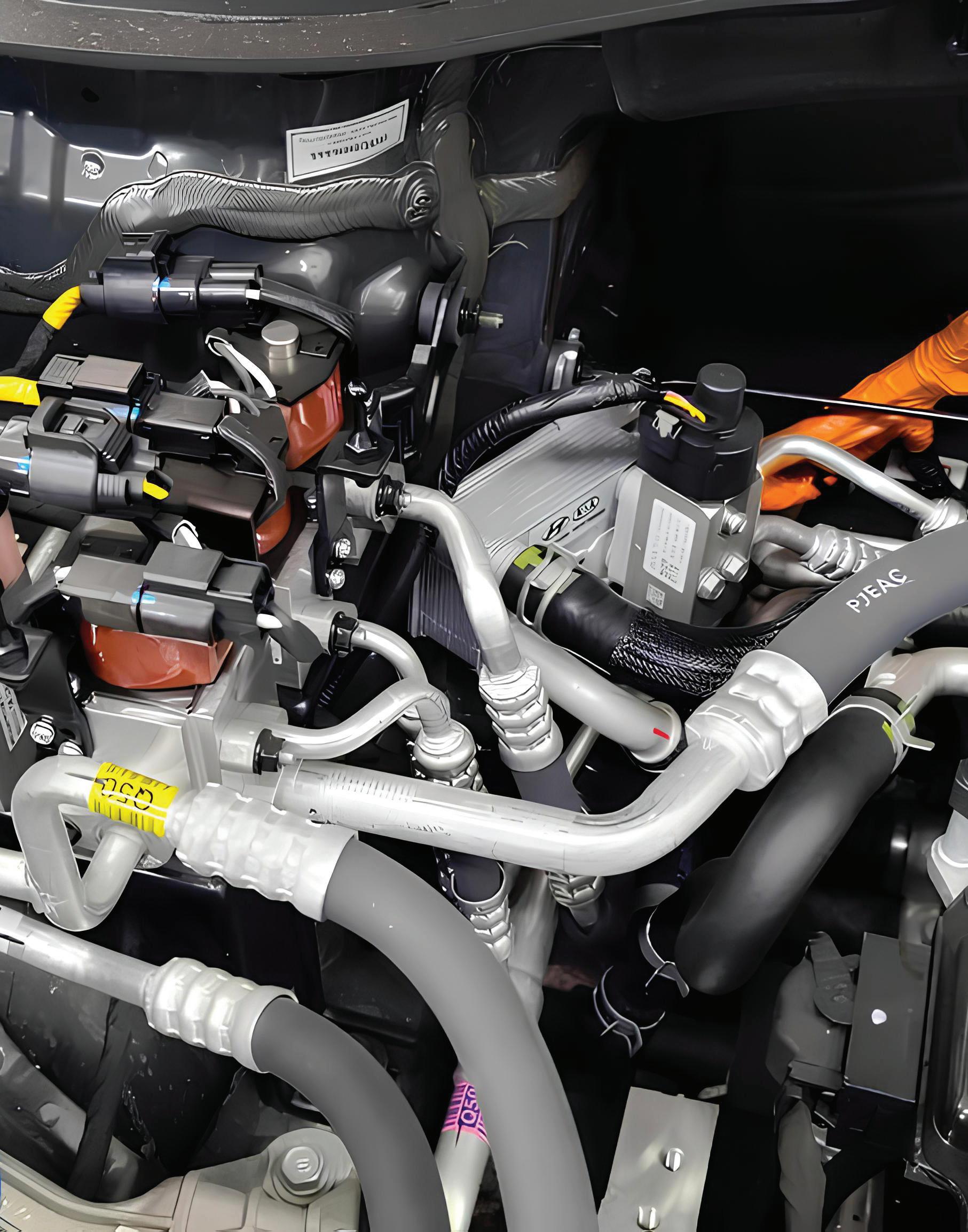
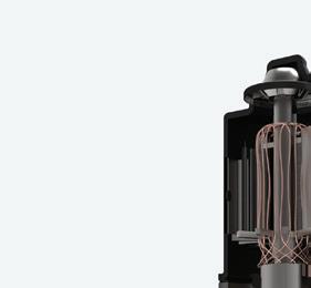
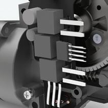
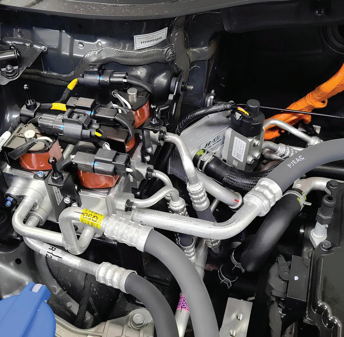
THIS PHOTO shows the complex valving and controls of the refrigerant on a 2022 Hyundai IONIQ, that is equipped with a heat pump system. PHOTOS BY AUTHOR
Vapor-Injected Scroll Compressors
One of the innovations that has allowed automotive heat pumps to function effectively in cold climates is the vapor-injected scroll compressor. This compressor design is a major upgrade over standard compressors, particularly in sub-zero conditions. The vapor injection technique involves splitting the refrigerant flow. A portion is routed through a secondary circuit, where it is expanded and evaporated to form a cool vapor. This vapor is then injected midway into the scroll compressor. By doing so, the system increases mass flow and compression efficiency, improving heating capacity even when the ambient temperature is below minus 4 degrees Fahrenheit (minus 20 degrees Celsius). The vapor injection system also reduces the temperature difference across the compressor, helping to prevent overheating and improving long-term durability.
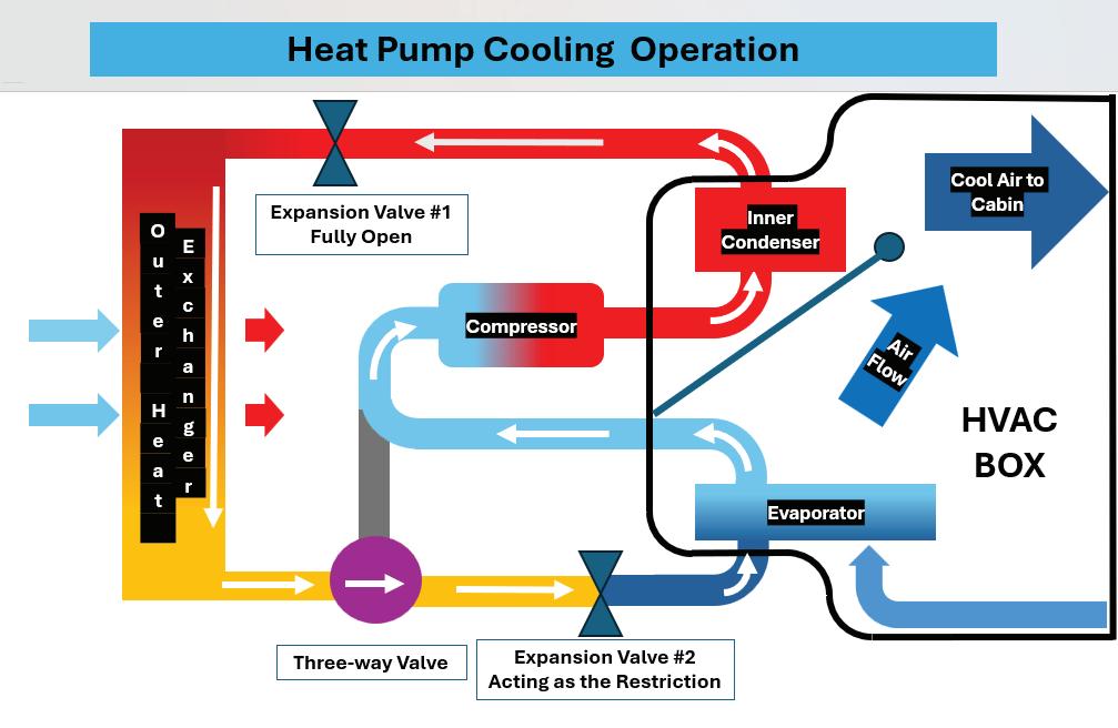
THIS DIAGRAM shows a simple heat pump system that is operating in cooling or AC mode. Starting at the compressor, the refrigerant leaves as a high-pressure gas, that flows through the inner condenser and then passes through the full open expansion valve #1. The refrigerant then is condensed to a liquid in the outer heat exchanger. This liquid then flows through the three-way valve that directs the flow toward expansion valve #2, that is in the restriction or operational mode. Once the refrigerant flows through expansion valve #2 it evaporates in the evaporator and then returns to the compressor to start the process over again. This cooling cycle is like the regular refrigerant cycle that we are familiar with.
PHOTOS BY AUTHOR


THIS DIAGRAM shows a simple heat pump system that is operating in the heating mode. Starting at the compressor, the refrigerant leaves as a high-pressure gas that flows into the inner condenser, but instead of flowing right through it is forced to condense, because expansion valve #1 is in restriction or operational mode. As the refrigerant is condensed the blower motor blows air over it, removing the heat of compression and warming the interior of the vehicle. After the refrigerant has been condensed, it flows through the restriction of expansion valve #1 and into the outer heat exchanger, that will now act as an evaporator. As the refrigerant evaporates it returns to a gas form and then flows through the three-way valve that will now direct the refrigerant flow back towards the compressor for the cycle to be repeated, because expansion valve #2 is now fully closed.

This compressor design is now featured in vehicles such as the Tesla Model Y, Ford F-150 Lightning, Hyundai Ioniq 5, and others. It has become the gold standard for coldweather heat pump performance in EVs.
Real-World Benefits and Range Preservation
Heat pumps provide quantifiable benefits to EV/hybrid drivers, especially in colder climates. Numerous real-world tests and independent studies have shown that vehicles equipped with heat pumps keep a higher percentage of their normal range in winter conditions compared to those using resistive heaters.
For example, Tesla vehicles equipped with their octovalve heat pump system have demonstrated winter range retention as high as 85 to 90 percent under sub-freezing conditions. Hyundai’s Ioniq 5 and EV6 models perform similarly, with


winter range drops of less than 10 percent. In contrast, early-generation Nissan Leaf vehicles without heat pumps often saw winter range drops of 30 percent or more. GM’s Cadillac Lyriq and Chevrolet Blazer EV, while equipped with heat pumps, still switch to resistive heating below minus 13 degrees Fahrenheit (minus 25 degrees Celsius), leading to slightly lower winter performance.
This difference in efficiency matters not only for range anxiety but also for occupant comfort. Heat pumps provide quicker warm-up times and better temperature stability, all while consuming less energy.
Manufacturers and Their Approaches
Tesla: Intelligent Thermal Management
Tesla’s heat pump system, introduced in the 2021 Model Y, features a vapor-injected scroll compressor and a unique part called the super manifold. The super manifold is a compact assembly housing multiple thermal management components like the octovalve, heat exchangers, sensors, and connections for coolant and refrigerant lines. The super manifold routes coolant and refrigerant between the cabin, battery, and powertrain components based on thermal demands. Tesla even uses the heat from the blower motor to aid in the warming of the passenger cabin. Combined with sophisticated software logic, the system ensures that heat is always used or stored optimally.
The Tesla system operates effectively down to minus 22 degrees Fahrenheit (minus 30 degrees Celsius) and uses overthe-air (OTA) updates to fine-tune its behavior over time. In effect, it’s a dynamic and intelligent system that adapts to environmental conditions and driver behavior, significantly improving winter performance.
GM: Ultium Energy Recovery
General Motors has integrated heat pumps across its Ultium-based EV lineup, including the Cadillac Lyriq, Chevy Equinox EV, Blazer EV, and Hummer EV. These systems include a patented energy recovery func-
tion that captures waste heat from the battery, motors, and power electronics. This recovered heat is used to warm the cabin or precondition the battery before charging.
However, GM’s system may not be as capable at lower temperatures as some others. Below minus 13 degrees Fahrenheit (minus 25 degrees Celsius), it automatically disables the heat pump and switches to PTC resistive heating. While this ensures reliability, it sacrifices efficiency and range. Nevertheless, the system is reported to improve cold weather driving range by 10 percent under typical winter conditions.
Ford: Engineering for Durability and Range
Ford switched to a vapor-injection heat pump system in the 2022 model F-150 Lightning and 2021 Mach E. The system includes three electronic expansion valves, two cyclonic liquid-gas separators and a large suction accumulator to prevent liquid “slugging events” from entering the compressor. Any liquid refrigerant, even small droplets, which enter the compressor may not only cause damage, but this refrigerant liquid reduces the compressor’s efficiency. Providing only gas-phase refrigerant under low-load or cold climate conditions maximizes the system’s efficiency.
Ford’s heat pump system can function in various modes, managing complex thermal demands from the passenger cabin, battery, and drivetrain. Ford kept a 5-kW resistive PTC heater in the cabin for backup heating, ensuring consistent performance even in severe conditions.
Hyundai and Kia: Quiet Leaders in Efficiency
Hyundai Motor Group has quietly become a leader in heat pump technology. Vehicles like the Hyundai Ioniq 5, Kia EV6, and Genesis GV60, feature vapor-injected compressors, waste heat recovery, and seamless integration with battery thermal systems. Real-world testing has shown these vehicles keep 90 percent or more of their rated range in sub-zero conditions.
Hyundai’s systems are not only efficient but also dependable, with fewer


service-related complaints than other OEMs. Their approach focuses on smart control logic and thermal synergy rather than proprietary hardware like Tesla’s super manifold.
Nissan Leaf: An Orifice Tube
The Nissan Leaf’s heat pump system uses both an expansion valve and an orifice tube, depending on the specific mode of operation. In cooling mode, the system employs a thermal expansion valve (TXV) to regulate the flow of refrigerant into the evaporator. During heating mode, the system incorporates an orifice tube as a fixed metering device. This orifice tube creates a pressure drop, allowing the refrigerant to absorb heat effectively. The Leaf also incorporates a PTC heater for cold weather reliability.
Toyota: Dependable and Evolving
Toyota’s Prius Prime PHEV features a heat pump system that uses a gas injection scroll compressor and a compact liquid-gas separator. This allows the vehicle to work efficiently in temperatures down to 14 degrees Fahrenheit (minus 10 Celsius) without engaging the gasoline engine. While effective, Toyota’s system does not yet match the coldweather performance of Tesla or Hyundai.
The bZ4X and Lexus RZ use updated heat pump systems, and Toyota is expected to adopt more advanced thermal


THE 2022 IONIQ also uses a refrigerant-to-coolant heat exchanger for thermal management of the high-voltage battery system. PHOTOS BY AUTHOR


technologies in future models as EV adoption expands.
Diagnostics and Servicing Heat Pump Systems
As heat pumps become standard equipment, technicians must become familiar with their operation, failure modes, and diagnostic procedures. One of the most critical aspects of heat pump service is refrigerant and oil charge levels. These systems are extremely sensitive to refrigerant and oil charge levels and even small deviations can impact performance.
In modern automotive heat pump systems like those found in vehicles from Kia and other manufacturers, traditional A/C pressure gauge readings can be misleading or even meaningless without proper context. Unlike older A/C systems with the traditional refrigerant flow paths, heat pump setups use complex multi-valve configura-
tions, vapor injection, and variable-speed electric compressors. These systems constantly adjust refrigerant routing based on cabin demand, battery conditioning, and ambient temperature. As a result, pressure gauges connected at standard service ports may not reflect the actual operating pressures inside the active loop at a given moment. For example, the system could be routing refrigerant through an isolated sub-circuit or temporarily idling the compressor, causing gauges to show low or even static pressures despite the system functioning correctly. Diagnosing these systems requires more than just gauges, it will require scan tool data understanding, knowledge of refrigerant flow modes, and sometimes even thermal imaging to interpret system behavior accurately.
Most manufacturers provide detailed refrigerant flow diagrams for heat pumpequipped vehicles. These not only illustrate
UNMATCHED

how the system routes refrigerant through various components during different heating and cooling modes, but they also show the components used in the system. This can be a great aid in diagnostics and proper service procedures.
When servicing heat pump-equipped vehicles, removing or recharging the refrigerant will involve a special procedure to allow access to all the internal passages and components, due to the system’s multiple refrigerant paths.
Unlike conventional A/C systems, these vehicles can trap refrigerant in dormant parts of the circuit and not allow the refrigerant to be fully recovered by simply attaching an A/C recovery machine.
To ensure complete and safe refrigerant recovery, the system must be powered on and placed in an operational mode that fully activates the refrigerant circuit. This is typically done using a scan tool to com-


Experience Schaeffler’s reliable OEM repair solutions, engineered for quality and efficiency. Maximize uptime, reduce costs, and ensure easy maintenance with our durable components.
www.vls.schaeffler.us

mand the HVAC system into a “refrigerant evacuation” or “service mode” or “full flow mode” which opens all necessary valves, solenoids, and flow paths, and may also engage the compressor. Following this procedure ensures that all refrigerant is properly evacuated before any disassembly is performed. Automakers like GM, Tesla, VW, and others outline these steps in
their official service procedures to ensure proper and thorough evacuation.
Without this step, a significant amount of refrigerant can remain trapped in isolated components, posing safety risks and compromising system performance after reassembly.
The same procedure must be used again to properly fill/recharge the system after

or loop of the system and that is why the pressure readings in the next image, to the right, are static.
the service or replacement of parts has been completed.
Always consult the vehicle manufacturer’s service procedures and use a certified recovery machine to safely extract and contain the refrigerant before opening any part of the system. And use all the needed precautions around any of the A/C system’s high-voltage equipment.

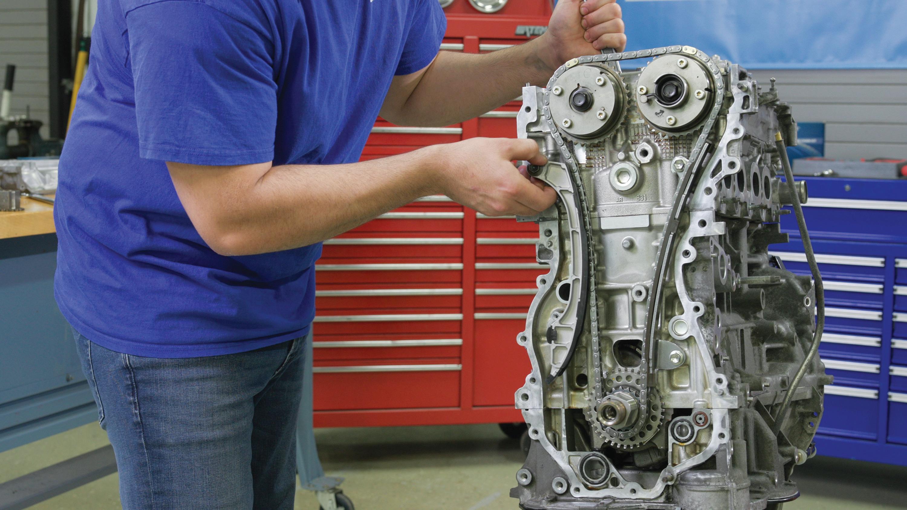

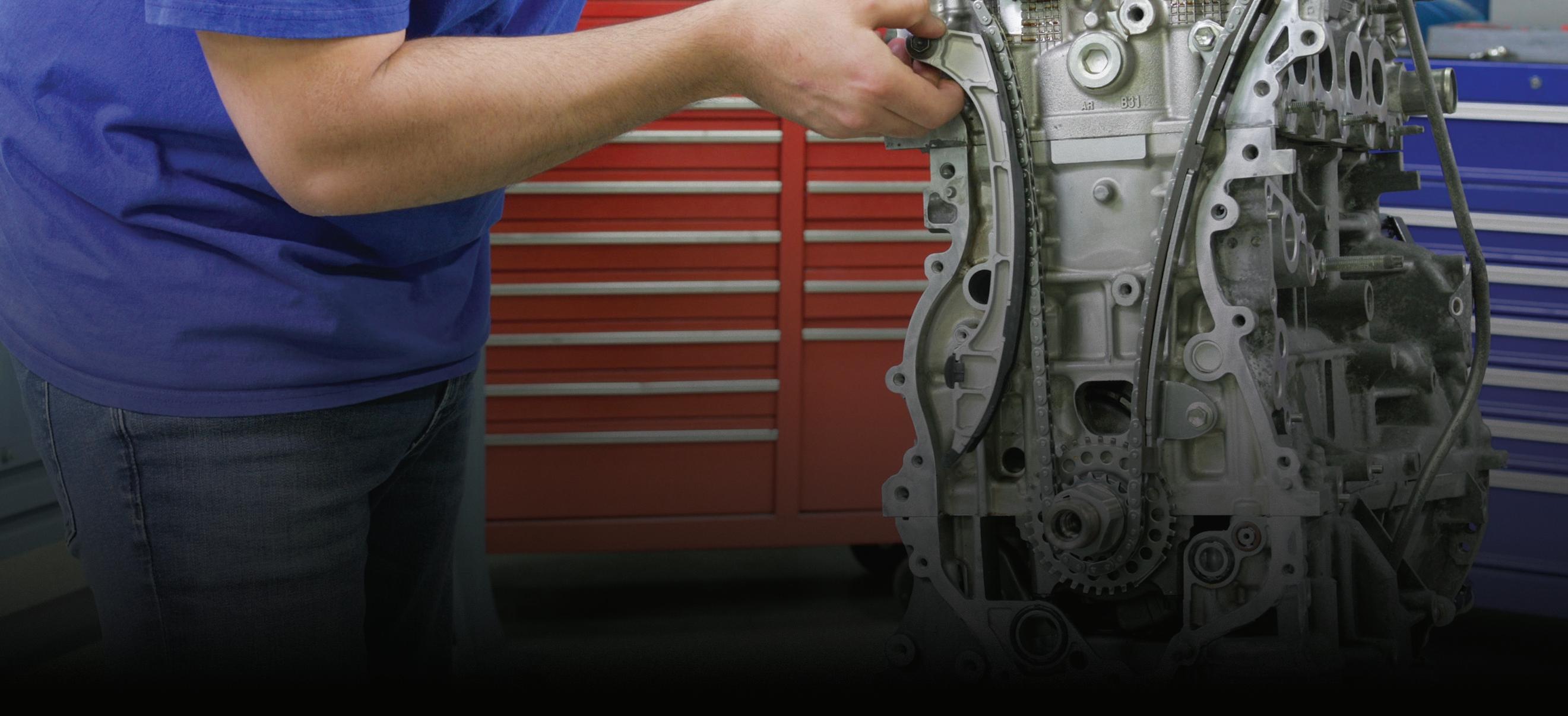


THIS DRAWING shows the refrigerant flow through the IONIQ heat pump system when in heat mode. Notice where the AC charge fittings are. They are in a dormant part
PHOTOS BY AUTHOR
THIS SCREEN shot is an example of the pressure gauges on a fully functional heat pump system. Note that the pressure gauge readings are similar, but the system pressures on the scan data show that the system has pressure and is functional.
PHOTOS BY AUTHOR

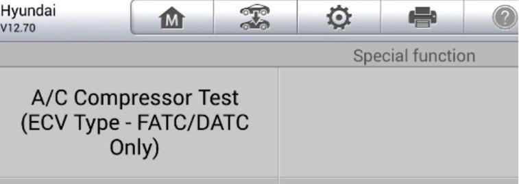
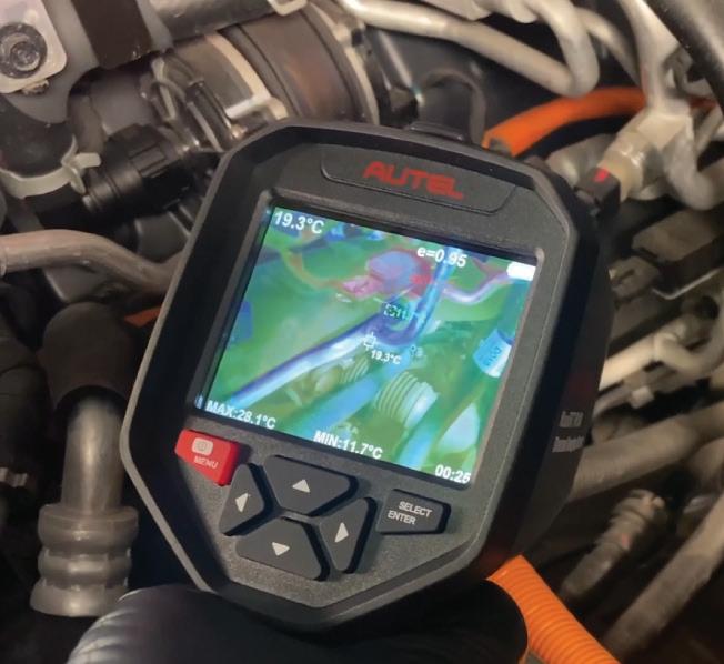
Scan tools are essential for diagnostics and service. Technicians should monitor parameters like compressor RPM, valve positions, refrigerant pressure and temperature, and ambient sensor data. For example, a failed temperature sensor can cause the system to misjudge whether heat should be drawn from the outside or whether to switch modes entirely.
Listen for compressor pitch changes or unusual vibrations, which can indicate bearing or internal damage. Modern systems may run the compressor even when the HVAC is off to maintain battery thermal stability.
Software updates are also crucial. Tesla, GM, Hyundai, Ford, and others all release periodic updates to improve sys-
tem behavior, correct bugs, or recalibrate control logic. Some vehicles may need a software update rather than a hardware replacement to resolve HVAC concerns.
Recalls and Real-World Issues
Even with their efficiency benefits, heat pump systems are not immune to problems.
Tesla experienced issues with early Model Y systems, where faulty sensors or misbehaving valves led to heat loss in extreme cold. A recall affecting more than 25,000 vehicles resulted in an OTA update and, in some cases, sensor replacement.
GM vehicles have faced criticism for losing heat below minus 13 degrees Fahrenheit (minus 25 degrees Celsius), though the company clarified that this is intentional fallback behavior. Still, customers expecting consistent cabin heat have reported dissatisfaction.
Hyundai issued service campaigns for early Kona EVs due to refrigerant contamination, which affected heat pump performance. These campaigns included flushing, recharging, and reprogramming the HVAC module.
Nissan’s Leaf, particularly in early models, suffered from sticking flow valves that caused intermittent heating. Software updates and mechanical valve replacements resolved most of these issues.
The Road Ahead: Smarter, More Efficient Thermal Management
Heat pump systems are expected to undergo further development in the future. Manufacturers are already exploring AI-driven thermal algorithms that learn from driver habits and environmental conditions. Future systems will be even more integrated, allowing waste heat from
every component including regenerative braking systems to be reused.
Vapor-injected compressors will become the norm, and newer refrigerants with better thermodynamic properties are being evaluated to improve performance further. For technicians, this means training and scan tools will need to keep pace. Service information will become more specialized and needed for HVAC diagnostics.
What This Means for Technicians: Understanding the System
Automotive heat pumps are no longer high-tech extras — they’ve become essential systems that directly affect the comfort, efficiency, and range of today’s electric and hybrid vehicles. For technicians, understanding how these systems work and how they differ from traditional HVAC setups is critical for correct diagnostics and effective repairs. Heat pump systems involve advanced refrigerant routing, electronic valve control, and integrated battery thermal management, requiring a deeper level of system knowledge and confident scan tool use. As EV and hybrid adoption continues to rise, technicians who stay current with this technology will be better prepared to diagnose performance issues, solve heating and cooling problems, and meet customer expectations for comfort and efficiency, whether it’s during summer heat or winter cold.

is a seasoned professional at CARS Inc. in Oshawa with 40 years in the automotive industry. As a skilled technical writer and training developer, he holds licenses in both automotive and heavy-duty vehicle repair. Jeff excels in TAC support, technical training, troubleshooting, and shaping the future of automotive expertise.


THIS IS an example of a DTC that was set. Note that the expansion valve that set the code is part of a LIN bus network.
PHOTOS BY AUTHOR
A SCAN tool will be needed to diagnose these heat pump systems, and many allow for automated self- test options. We will also need the scan tool to display system pressures as we have seen that the AC gauge set may not provide the tech with useful information.
PHOTOS BY AUTHOR
THE USE of a thermal imager will help diagnose the heat pump system by identifying hot/cold zones, reversing functions and proper refrigerant flow.
PHOTOS BY AUTHOR
JEFF TAYLOR
Haven’t purchased from ETE in a while or ever?


NEW or RETURNING customers - Shift to ETE now and get a $100 Amazon gift card every time you buy an ETE LIKE NEW ONLY BETTER transmission, engine, transfer case, or differential for 100 days.
America’s #1 Remanufactured Transmissions
World’s Best 3-Year, Unlimited Mile Warranty
Same-Day Shipping on Most In-Stock Products
Remanufactured in the U.S.A.
Award-Winning Customer Service & Tech Support Powered by ATSG
WAIT, HOW DOES IT WORK?
The clock, and your rewards, starts with your first purchase. Then, every drivetrain product purchase for the next 100 days earns you another $100 Amazon Gift Card. Easy, Fun, and Kinda Awesome.


SUITE-STAKES S T


BE SURE TO
The Bigger Picture
When you can’t see the forest for trees, you tend to miss a lot. My advice? Take a step back and see the bigger picture.
BY BRANDON STECKLER // Technical Editor
I RECEIVED A CALL from a friend of mine (Rick) out of Chicagoland. It seems he was faced with a 2019 Dodge Durango with a 3.6L engine, and the complaint of DTC P0300 and misfires being flagged for cylinder No. 1. According to Rick, the PCM only registered misfires above 3,000 rpm.
Rick evaluated both the ignition and fuel injection system (with no issues found) prior to reaching out to me. Rick captured and shared engine-mechanical waveforms for the entire engine, overall from his digital storage oscilloscope. The waveforms reflect cranking-intake pressure and relative compression (Figure 1). This capture was sent with the question on what I see wrong with cylinder No. 1.
Initial Analysis
As we’ve discussed in previous articles, it’s important to understand the limitation of the test you are performing. The relative compression test is capable of showing a cylinder(s) deficient in compression as this typically affects starter load. And, although the test results will infer a loss of compression (when that fault is present) the result truly reflects a variation in starter load.
THE DATA DOESN’T LIE
WELCOME BACK TO ANOTHER EDITION OF “THE DATA DOESNT LIE,” A REGULAR FEATURE, WHERE I POSE A PUZZLING CASE STUDY.
However, if there is no significant variation in compression between cylinders, the results of the test may not display the fault.
With that, the BLUE relative compression test indicates variation in starter load, but for multiple cylinders (almost in an erratic nature). The GREEN trace shows a rhythmic variation in contribution to the intake manifold.
A bit of research regarding the configuration of this engine offers a clue that is worth pursuing, in my opinion. When researching the firing order of this particular engine, we also learn the cylinder configuration, and where bank No. 1 is (Figure 2). After analyzing both the above figures. I was able to offer some advice to Rick on what to pursue next.
The
Data Doesn’t Lie
With all the information in front of us, and the desired information not yet obtained, we are faced with deciding how to proceed.


Here are some bullet points of what we know to be factual, and I will ask all of you, diligent readers, for your input on what they mean to you, collectively:
• MIL illuminated and P0300 stored in PCM history
• Misfires only occur at approximately 3,000 rpm
• Cylinder No. 1 is the only cylinder that continues to flag misfires
• Engine-mechanical waveforms and engine configuration data combine to offer a clue
Given this information, what would you do next?
1. Condemn intake valve integrity for cylinder No. 1
2. Condemn exhaust valve integrity for cylinder No. 1
3. Condemn engine for multiple cylinders’ valve integrity
4. Inspect for a bank-to-bank breathability issue
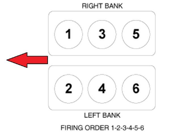
2 This 3.6L engine’s mechanical configuration combines with the data from figure No. 1 to offer a clue about how each bank of the engine breathes, relative to the other.
FIG. 1 The relative compression trace and cranking intake-pressure traces offer clues about overall breathability of the entire engine from one quick-to-grab capture. PHOTO BY AUTHOR
FIG.
PHOTO BY AUTHOR
Solved: A Jeep With Compression Issues
From June 2025, Motor Age
BY BRANDON STECKLER // Technical Editor
WHAT WOULD YOU RECOMMEND doing next, given the data bullet points in last month’s challenge?
1. Retime the camshafts
2. Measure the duration of the intake valve for cylinder No. 1
3. Replace engine due to damage low-end
4. Dose each cylinder with oil to increase compression ratio
For those of you who chose answer No. 2, congratulations! The intake trace and
in-cylinder trace both show a significantly late IVO event. Measuring the duration of the intake valve for cylinder No. 1 proves it’s extremely insufficient. This infers either a severely worn intake cam lobe or (more likely) collapsed lifters. The engine was simply cranked for an extended period of time (for the lifters to purge) and the engine started/ran without issue (See photo).
Answer No. 1 is incorrect. If the cam timing was the issue, all of the cylinders would have the same faulted outcome

FIG. 1 The duration of the intake valve was significantly insufficient at only 51 degrees. This suggests either a significantly worn cam lobe or lifter issue. Considering all cylinders suffered the same issue, the likely fault was air-bound/collapsed lifters. The engine was cranked repeatedly to purge air from the lifters and the engine started/ran normally. PHOTO BY AUTHOR
(considering the configuration of this in-line four-cylinder engine).
Answer No. 3 is incorrect as there is no indication of a low-end engine issue present.
Answer No. 4 holds merit because introducing oil to the cylinder would indeed increase the compression however, significant only if the low-end had worn to cause the compression loss.
Be sure to read the next Motor Age issue for the answer to this month’s challenge and what was discovered!

BRANDON STECKLER is the technical editor of Motor Age magazine. He holds multiple ASE certifications. He is an active instructor and provides telephone and live technical support, as well as private training, for technicians all across the world.

SCAN TO READ MORE ARTICLES LIKE THIS


From grungy transmissions to grimy engine blocks, nothing cleans better than Ranger’s signature stainless steel line of aqueous cleaning and degreasing systems. Durable 304 stainless steel construction is resistant to harsh chemicals and delivers the strength to endure years of hot-washing with minimal upkeep. All models feature twin heaters for quick startup, large-volume solution tanks, oil skimming system, low-water shutoff, friction-drive turntable system and gasket-free door. Beauty combined with strength, performance and durability. Order now at www.bendpak.com/wash


Looking Back on 25 Years of EV Technology

The future is getting here quickly, and for many, EVs are a practical alternative to ICE-powered vehicles.
BY CRAIG VAN BATENBURG
WHAT HAS HAPPENED WITH EVS since their birth in the late ‘90s? This is a technical walkthrough of the evolution of hybrids that led to EVs, including the last 15 years of lithium packs and planning for the future.
A Cult Hybrid
The original Honda Insight has a “cult” like following. How did this odd-looking hybrid attract so many fans? Honda introduced the first hybrid to America in December 1999. It was a month that changed a lot of what we thought we knew about cars. The first generation of the Insight was discontinued in 2006. The Insight prototype, by another name, was first shown to the public at the Tokyo Auto show in 1997. It was a two-passenger sports coupe. It had been in development for about three years prior to that. In the summer of 1999, it was named the Insight and Honda released the details. Before they were sold, a few Insights were available to reporters and others for road testing. Stan Stephenson, former editor of Motor Age magazine, and a member of IMPA (International Motor Press Association) had a pre-production Insight in October of 1999. He called me at my home is Worcester, Mass. and I flew down to Philadelphia, Pa. the next day for my first drive in what would become my first of many hybrid car purchases.
First year sales were limited to less than 6,000 hybrids due to a lack of
WITH MORE solar and wind farms added to the grid, EVs are cleaner now than in 2011.
production ability. Insights were made in Japan in the same small factory that built the NSX and the S2000. It had an allaluminum chassis and was very high tech for its time in regards to aerodynamics, engine, hybrid software, and electronics. The first year it was only available with a five-speed manual transmission. A little Honda History: Honda’s first use of the Integrated Motor Assist (IMA) system was for F1 racing. This was to add more torque to the ICE coming out of the corners when rpms are low and torque is not enough to get maximum traction. It never saw a race as it was not allowed. This type of system was finally used by F1 in 2009. If you haven’t been keeping up with Formula One racing, take a look and while you are there, check out Formula E. Adding more torque electrically to the crankshaft works great as Honda has proven on and off the track. This Insight was light weight, streamlined, and efficient. It handled well and ran like a Honda. The old Insight was one of a kind.
In December 1997 Toyota introduced the first mass-produced hybrid vehicle as a M/Y 1998 to the drivers in Japan. In model year 2001 it was brought to North America. Sales of the first-generation Prius were slow as it was a new idea at a time when gasoline was $1.50 per gallon and there were no government financial incentives. Sales increased drastically when the second generation was sold in 2003 as a M/Y 2004. Some local, state, and federal governments worldwide stepped in to help lower the cost of ownership. Some HOV (High Occupancy Vehicle) lanes were opened to hybrids with only the driver. These incentives were debated and some people that loved the old days objected. The hybrid incentives went away years ago. Today the incentive is all about plug-in cars and those are still debated.
The Gen III Prius liftback (M/Y 20102015) sold over 1.3 million units in the USA without any incentives and became a mainstream car. The first Prius was an original idea. Toyota deserves all the
credit it has been given to bring a modern hybrid car to the masses. Its aerodynamic shape, particularly the second generation, made it stand out. Unlike the two Honda hybrids, which were the only other HEVs at that time, the Prius was a family car that could carry up to five passengers. The second-generation Prius was larger and provided enough interior space to be classified as a mid-sized vehicle. The Prius has also been certified as a SULEV, or Super Ultra Low Emission Vehicle.
Toyota hybrids sold very well in 2024 as the company now offers hybrid versions of all of the important models it sells, except the low volume Toyota GR 86, Supra, and Lexus IS. In M/Y 2025 the Camry, Land Cruiser, Sienna, Venza, RAV4, and Sequoia are only available as hybrids in America.
Next up with hybrids was Ford. In 2004, Ford released the M/Y 2005 Es -
cape hybrid. This was the first hybrid SUV, and the first hybrid vehicle built in North America. Sales of the hybrids went very well, although they were in limited simply because of a shortage of hybrid parts from Japan. The Ford Escape SUV received many accolades and looked nearly identical to the non-hybrid Escape. The major differences in appearance are badges or external markings that indicate it is a hybrid and a barely noticeable vent near the rear quarter window on the driver’s side of the vehicle until 2010. The vent was there as an inlet for the HV battery evaporator. The standard Escape hybrid is front-wheel drive, with an Intelligent 4WD system that is optional. This option made the Escape the first 4WD hybrid.
In 2006, Ford released a hybrid version of the Escape’s cousin, the Mercury Mariner. These SUVs feature a transmission that was designed by Volvo and Aisin. The


IN 2006, ACDC was holding multi day classes. This picture was from 2007. This is most of what was selling in large numbers. PHOTO: ACDC
IN 2004 ACDC had two Hybrids to teach with. A 2000 Honda Insight and a 2004 Toyota Prius. PHOTO: ACDC


Toyota eCVT was similar in design and function to the Ford unit. Aisin, a Japanese company, was involved in both hybrid systems during development in the ‘90s. This Ford hybrid had the technology, as well as the ability to be powered solely by battery power. They have a towing capability of up to 1,000 pounds, the same tow rating as a regular four-cylinder Escape or Mariner. The last model year for the Escape HEV was 2012. Ford, Volvo, Aisin, and Toyota all worked at times on the basic components and operation of Ford’s hybrid system as they are very similar to what is found in Toyota hybrids. This has led many to conclude that Ford was simply buying the system from Toyota. This was not true. The concept of using two electric motors to create a transaxle suitable for hybrid technology was first explained by an American engineer in the 1960s. This concept is actually an adaptation of the planetary gear set Henry Ford used in the original Model T in 1909. Going forth with the basic idea of using a planetary gear set as a power-split device, Toyota entered into a partnership with a Japanese transmission design and manufacturing company, Aisin, in the early 1990s to develop a hybrid transmission with two electric motors. These companies continued to work together for years (until their contract expired), and then Toyota decided to continue development of the transaxle on its own. The result was the transaxle introduced in the 1998 Prius.
In the meantime, Volvo joined forces with Aisin and continued to develop the eCVT transaxle. In 1999 Ford purchased Volvo and the technology. Because of the basic roots, the Toyota and Ford power-split units are quite similar. Due to the similarities and to avoid legal problems, Ford licensed some of the technology from Toyota and Toyota licensed some technology from Ford. Toyota holds over 150 patents on the technology, and Ford has received more than 100 patents on its design.
The bottom line: Aisin supplies the transmission used in the Ford Escape


hybrids and Toyota makes most of their own eCVTs with Aisin helping out on the Lexus GS and LS hybrid models. Toyota does not supply hybrid components to Ford. Both Ford and Toyota state that Ford received no technical assistance from Toyota during the development of their hybrid system.
At General Motors, the 2-Mode transmission uses three planetary gear sets, two motors, and a similar approach as the Prius in terms of cranking the ICE to
start and also the constantly variable ICE to road speed that is unique to planetary gears. These two-mode systems were installed in Cadillacs, GMCs, and Chevrolets. They were all big SUVs and pickup trucks. The sales were low so after the mid-2010s, they were discontinued.
High Voltage Batteries in Electric Cars and Trucks
Modern electric vehicles (those built since 2008) have always used a lithium-based


IN 2011 the Chevy Volt and Nissan Leaf were selling well. ACDC added them right away and plug-in cars were added to the classes.
PHOTO: ACDC
THIS CHEVY Bolt came out in 2017 and was added to the fleet.
PHOTO: GENERAL MOTORS


cell. In the 25 years since Toyota and Honda started selling hybrids in the USA, every high voltage part has been designed with less weight, more power, and has lasted longer, was more efficient, and cost less. The technology and manufacturing processes have come a long way in 15 years.
Affordable pure electric cars came to a market in 2010. (The Tesla Roadster was sold in M/Y 2008). To get enough range on one charge, two or three large cells were connected in parallel to form modules. They were then connected in series to get to the desired voltage, usually 400 volts DC. Tesla had a different idea, using many small cells in parallel. The primary issue of early EVs was short driving ranges and long charge times.
The range limitations of EVs were due to battery technology. As you know, over 10 years ago, a high-end Telsa had a range in excess of 400 miles and the 2017-20 Chevy Bolt battery pack had well over 200 miles of range. The 2022 M/Y Lucid Air has a range of over 500 miles. Today, many pure EVs have over 300 miles of range and sell for under $40,000 without any government incentives.
We are at a time when an EV is practical for those drivers who know their typical route. If equipped with a fast charge port, some EVs can recharge to about 80% SOC in under 30 minutes. Other “fast chargers” take longer. The future is getting here quickly. EVs for many, are a practical alternative to ICE-powered vehicles, depending on their lifestyle and the other means of transportation available to them.
Some of you may wonder why we are going to EVs so quickly. That question is asked in some form in almost every class I teach. This question allows me to do two things: teach a short five gas lesson (call this a chemistry class) and cover the effects of the build-up of carbon dioxide in the atmosphere. Once the science class is over, we can move on. I also pose this question: How does six pounds of gasoline (one gallon) create 19 pounds

of carbon dioxide? Where did the other fuel come from?
The road to zero emissions has been long and we are not there yet, but every year we get closer to a major shift away from the internal combustion engine to cleaner transportation. EVs started to sell in tiny numbers by the mid-’90s in California. That was 30 years ago. As the EVs are selling more each year, the electric grid is also getting cleaner. Less coal and oil used to generate electricity and more hydro, wind, and solar has come online. An older EV is cleaner now than it was in 2010, because the grid is cleaner.
We can all learn from the past. It is fun to revisit the old days. Old car shows are popular. Classic cars are cool! No one doubts that. For two big reasons, safety


IN EARLY 2025, (from left to right) four interns Gavin, Mike, Mees, and Thijs worked together as an extension of their Dutch College at ACDC. Craig is in the middle.
PHOTO: ACDC
DEB VAN BATENBURG leads the first hybrids sold in the USA (the Prius and Insight) on a fuel economy run. PHOTO: ACDC
THE YEAR is 2000 and Craig stands next to his new Honda Insight Gas/ Electric Hybrid. PHOTO: ACDC


and tail pipe pollution, we ended up here and the entire world has responded. We just finished hosting four Dutch automotive college seniors for a total of five months. Two at a time for 10 weeks. We all had lunch together almost daily and the topic of conversation included
EVs in Europe, particularly the Netherlands. Their EV market share has been growing. Transportation is a major contributor to climate change, accounting for roughly a quarter of global greenhouse gas emissions. In the United States, it’s the largest single source of greenhouse

gas emissions, representing about 28% of the total. These emissions primarily come from burning fossil fuels in vehicles like cars, trucks, ships, and airplanes. The cars we fix will continue to change until we have done what we can to slow down an overheating planet.

CRAIG VAN BATENBURG is the CEO of ACDC, a hybrid and plug-in training company based in Worcester, Mass. ACDC has been offering high voltage classes since 2000, when the Honda Insight came to the USA. When EVs were introduced in 2011, ACDC added them to their classes. Reach Craig via email at Craig@ fixhybrid.com or call him at (508) 826-4546. Find ACDC at www.FIXHYBRID.com.
SMALL BRAKE CALIPER PRESS
Works on small and medium single piston brake calipers that are found in subcompact to mid-size vehicles
Centrally located Acme threaded screw for durability, speed and ease of use
Size Range is 1" to 3"


TESLA ALLOWED aftermarket shops access to scan tools, parts, and service information so the Tesla came along at that time. The electric Zero SF/R motorcycle was just for fun. PHOTO: ACDC


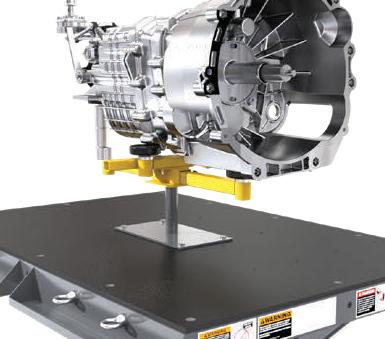
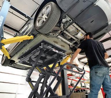

AUTOMOTIVE PRODUCT GUIDE
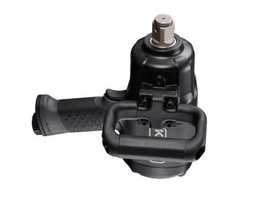
Features magnesium front and rear housings
The K-Tool International Super Duty 1” Drive Air Impact Wrench, No. KTI81791, offers over 2,700 ft-lbs of breakaway torque and 1,000 blows per minute. It features a variable speed trigger with multi-speed control, a side handle for increased user control, handle exhaust that directs airflow away from the work area, and a seven-vane super motor that provides 5,500 rpm. Magnesium housings and composite center housing offer strength and durability with a lighter weight, and the tool as a whole only weighs 12.4 lbs.
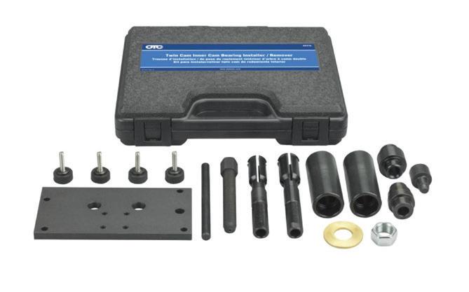
Designed to trap needle bearings
The Twin Cam Inner Cam Bearing Remover/ Installer Kit from OTC Tools contains the tools needed to remove and install inner cam bearings without damage to the crankcase. The bearing puller is designed to trap the needle bearings and keep them from falling into the crankcase. The installation tools are designed to press on the outer-most diameter of the bearing, eliminating damage to the bearing, cam, or case. The press adapter will also set the bearing to its proper depth. Removes and installs both 7/8” and 1” ID bearings.

Allows hands-free interaction with data and real-time assistance
The Jaltest Diagnostics AR from Cojali USA allows users to interact hands-free with electronic units, technical data, and real-time assistance without interrupting the job at hand or requiring any backand-forth between a computer and a vehicle. The mixed-reality glasses are fully customizable, allowing them to be tailored for repair bays, end-of-line testing, training programs, and more.

Offers over 30 hours of battery life
The R134A & R1234YF Smart Manifold Gauge Set from Mastercool features a 4.3” color touchscreen for easy viewing of pressure and temperature readings, an automatic shut-off to save battery life, and unit conversions between pounds, ounces, kilograms, and milliliters. It offers extensive pressure readings in psi, bar, MPa, kg/cm2, and kPa for versatility, while the built-in refrigerant database provides factory-recommended capacities for precise recharging. The long-lasting rechargeable lithium battery offers over 30 hours of use and USB-C charging.

Cord spans 20’
The Schumacher Electric 12A Level 1 Portable EV Charger, No. SEV1670, provides up to 12A of charging power using a standard NEMA 5-15 120V AC household outlet and includes a universal J1772 connector that makes it compatible with a wide range of electric vehicles. The SEV1670 features a 20’ cord and ergonomic design for optimal use. The main housing has an IP66 rating, and the charging gun includes a rubber cover for water and dirt protection. Built-in LED indicators allow for easy monitoring of the charge status. The SEV1670 offers protection against leakage, under voltage, overvoltage, overcurrent, overtemperature, ground faults, and relay faults.

Includes more than 250 undercarriage illustrations
The Vehicle Lifting Points from the Automotive Lift Institute (ALI) covers thousands of models — years 2000 to 2025 — of cars, SUVs, vans, light duty trucks, and EVs sold in the U.S. and Canada. It includes more than 250 undercarriage illustrations, as well as suggestions for safely lifting vehicles. The new digital version has the same content and layout as the print guide, with the added benefit of immediate, always-on access through any device for maximum convenience. Users can customize the view with magnification, choose light or dark mode, or go full screen. The digital version gives users access to up to 3 devices, create annotations and make notes, and find a vehicle using the keyword search function.
AUTOMOTIVE PRODUCT GUIDE
Quickly shares and documents via email
The Milwaukee Tool M12 Auto Shop Borescope with Wi-Fi File Sharing is optimized for the automotive shop, delivering simplified inspections and faster repair approval. Users can quickly share and document findings from the 5.5” HD touchscreen display, as well as add context to photos and videos through onboard drawing, audio, text, and video trimming features. Once connected to the shop’s Wi-Fi, it can quickly share and document findings via email for faster repair approval.


Built-in flow meter prevents false readings
The Lincoln PowerLuber Model 1884 is a dual-battery grease gun featuring a liquid crystal display that provides real-time battery level and grease flow readings. The Model 1884 has a rugged three-point base that provides stability without adding bulk, allowing access to tight spaces. It also includes a built-in LED light for enhanced visibility and a built-in flow meter that detects the loss of prime to prevent false readings.

Made of high-strength steel and lightweight aluminum


The Inductor® Max uses high-frequency magnetic fields to heat ferrous metals quickly and safely—without causing damage to nearby plastic parts or components. The PDR variation of this unit is designed to help remove soft dents and comes with our concentrator attachment and PDR Baton.


The 3-Ton Combination Service Jack, No. CSESJ30HN, from Cornwell Tools, is constructed of both high-strength steel and lightweight aluminum to provide a 3-ton lifting capacity while weighing only 65 lbs. Dual-pump pistons quickly reach service height. The jack has an over 4” saddle diameter with 4” minimum saddle height, and an 18.5” maximum lift height with bypass valves to prevent over-extension. Premium seals, hydraulic fluid, and components for a long, dependable service life. Manufactured to comply with the ASME PASE-2019 Safety Standard.
Includes safety valve, adapters, and hard case
The TEXA Forming Gas Kit & H2 Detect - AC System Leak Detection provides accurate and efficient leak detection for R134a/R1234yf/R744 refrigerant systems. When an AC system is missing the confirmed quantity, it’s a sign of a leak and needs repair. The kit allows users to confirm microleaks quickly and safely for an effective repair. The Forming Gas Kit comes with the Forming Gas Cart TTF 700, which is equipped with all the necessary tools to operate on AC systems, the Forming Gas Case, and the H2 Detect Sniffer, which detects any hydrogen in the air for locating the leak’s location.


TECHNICAL SERVICE BULLETINS
INFORMATION COURTESY OF MITCHELL 1

LINCOLN DON’T GREASE CONNECTORS
Here’s a tip from Lincoln. 2013-2018 MKZ hybrid vehicles using SOBDM-C module connectors do not require electrical/dielectric grease. If grease is applied, it may induce module communication concerns. DTCs U0293 and P0AA6 may be set. (Photo: Lincoln)

INFINITI
OIL DRAIN PLUG CAUTION
This bulletin specifically applies to 20162020 Infiniti Q50 and 2017-2020 Q60 vehicles equipped with a V6 engine, but also applies to engine oil drain plug cau-

tions on any vehicle. Over-tightening the oil drain plug can result in oil leaks and damage to the female threads in the pan. Whenever installing an engine oil drain plug on the afore-mentioned Infiniti vehicles, never tighten the drain plug greater than the specified torque value. Over-tightening may loosen the threaded insert in the oil pan. Also, always replace the drain plug gasket whenever installing the drain plug. Instead of the oil pan drain plug hole featuring integral threads, the oil pans in these vehicles feature a threaded insert. Over-tightening can loosen the threaded insert, allowing it to spin in its hole. Proper drain plug tightening torque value is 25 ft-lbs (33.5 Nm). (Photo: Infiniti) VOLVO COLLISION WARNING
This bulletin applies to 2016-2017 Volvo XC90, 2017 S90/V90/V90CC and 2018 S90 vehicles. The blind spot information system (BLIS) may not work and a text window and warning symbol
message may be seen. This affects SODL/SODR (side object detection left/ right) and SOD (side object detection). If a warning message “BITS system service required” occurs in the DIM together with DTC S0DR-U023292 and/ or SODL-U023392 software, perform an upgrade to the software according to TJ31543. (Photo: Volvo)
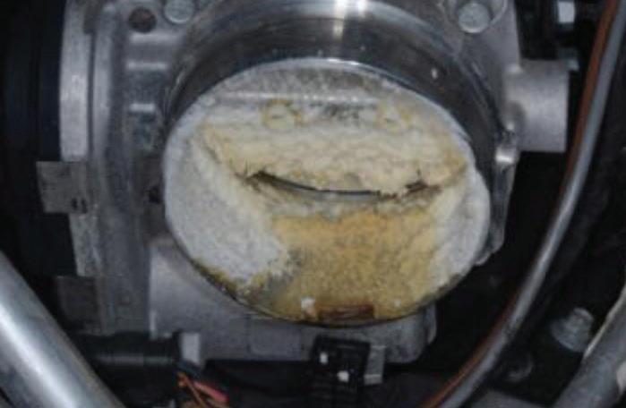
RAM ICEBURG WARNING
This bulletin applies to 2013-2023 RAM 1500 vehicles equipped with a 3.6L V6 24V VVT engine. The MIL may be on. Technicians may find DTC P2072 (electronic throttle control system, ice blockage); P2110 (electronic throttle control forced limited RPM) and/or P2118 (electronic throttle control motor current performance Bank 1). The engine may not start in below freezing conditions (minus 20 degrees Fahrenheit). The throttle body blade is icing up.
Warm the vehicle indoors. Remove the air cleaner resonator, clean and dry any water or ice. Clean out and dry any water or ice from the throttle body. Install the air cleaner resonator.
Remove the PCV valve/hose and clean out any water or ice. Install the PCV valve and hose. Remove and discard the original make-up air hose and air cleaner lid. Replace with
kit P/N 68631360AA. Also, replace the air filter P/N 68441763AA and engine oil filter 68191349AC and replace engine oil using 6 quarts of 5W20 oil. (Photo: Mitchell 1)
REDI-Sensor is ready to install quicker, so you can get TPMS done faster and more profitably.
4 SKUs = coverage for over 225 million vehicles on the road.


This bulletin applies to 2016-2019 Cadillac ATS, 2016-2018 CT6, 20162019 CTS and 2015-2018 Escalade vehicles, equipped with an 8L45 or 8L90 automatic transmission.
Customers may comment that the vehicle will not obtain Park at times. This condition may be caused by a damaged parking pawl and/or parking pawl actuator. The transmission may have experienced a park engagement while the vehicle was in motion or the transfer case obtained a neutral state.
Attempt to duplicate the No Park condition by operating the shift lever. The shift lever should move freely through all positions. Check the transfer case for proper operation in each range. Inspect the shift cable system and mounting bracket for any signs of visible damage or mis-routing.
Remove the transmission oil pan and valve body. Remove the park pawl actuator bracket and discard the bolts.
Remove the park pawl actuator. Inspect for damage, bent rod, or incomplete travel of the actuator. Inspect the park pawl for damage. If damage to the park pawl actuator and/or park pawl is present, replace the following:
• Park pawl actuator

CADILLAC NO PARK


• Park pawl
• Main shaft detent lever hub pin
• Park pawl actuator bracket
• Park pawl actuator bracket bolts
• Output carrier
Note: the transmission should be disassembled and cleaned thoroughly.
(Photo: Mitchell 1)

MAZDA FORWARD CAMERA
This bulletin applies to 2018 Mazda6, 2017-2018 CX-5 and 2018 CX-9 vehicles, all equipped with MRCC Stop and Go function. Some customers may complain about a message on the driver display: “Mazda Radar Cruise Control disabled under 20 mph.” The forward sensing camera (FSC) cannot detect target objects due to dirty windshield, fogger FSC camera lens, low visibility due to rain, fog or snow, insufficient light at night, direct or reflected sunlight on the SC, problem with the FSC, problem with the Autohold control function or problem with the electric parking brake.
Check for DTCs and address/repair as needed. If no related DTCs are present,
no repairs are needed. Simply clean the windshield and front radar sensor. (Photo: Mitchell 1)

FORD
MISSING ENGINE COVER
Some 2019-2022 Ford Ranger vehicles may exhibit a MIL on with DTC P0300, P0301, P0302, P0303, P0304 and/or P0316 stored in the PCM. This may be due to water buildup in the spark plug wells and corrosion on ignition system components. This may be the result of the engine appearance cover not being installed. Locate the two engine appearance cover mounting bosses on the valve cover. Make sure that the engine appearance cover stud bolts are installed to the valve cover. Tighten these to 89 in-lb.
Lubricate each grommet on the engine cover with silicone brake caliper grease and dielectric compound to aid in cover installation. Install the engine cover. Install the two stud nuts and torque to 89 in-lb. The engine appearance cover kit is available as P/N L1MZ-6A949-C.
(Photo: Mitchell 1)

GENESIS FUEL PRESSURE
This bulletin applies to 2019-2020 Genesis vehicles, where DTC U0109/ U010900 is stored and there is a communication error with the fuel pump control module (FPCM).
• Connect GDS to the data link connector.
• If there are any FPCM DTC related codes, replace the FPCM.
• Using a voltmeter, check the fuel pressure sensor (FPS) output voltage, Specified voltage is 5V.
• Check FPS output voltage at idle. Specified idle voltage is 1.4-3.2V.
• Test fuel pressure at the delivery line from the fuel tank. If FPCM is out of spec, replace the FPCM.
To replace the FPCM, turn ignition off and disconnect the battery negative cable. Remove the trunk rear transverse trim. Fold the LH luggage side trim to access the FPCM.
Disconnect the FPCM connector and mounting nuts and remove the FPCM. Install the new FPCM in reverse order.
(Photo: Mitchell 1)

MID-RISE LIFTING REDEFINED
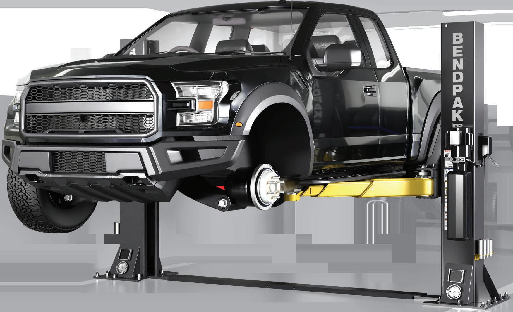


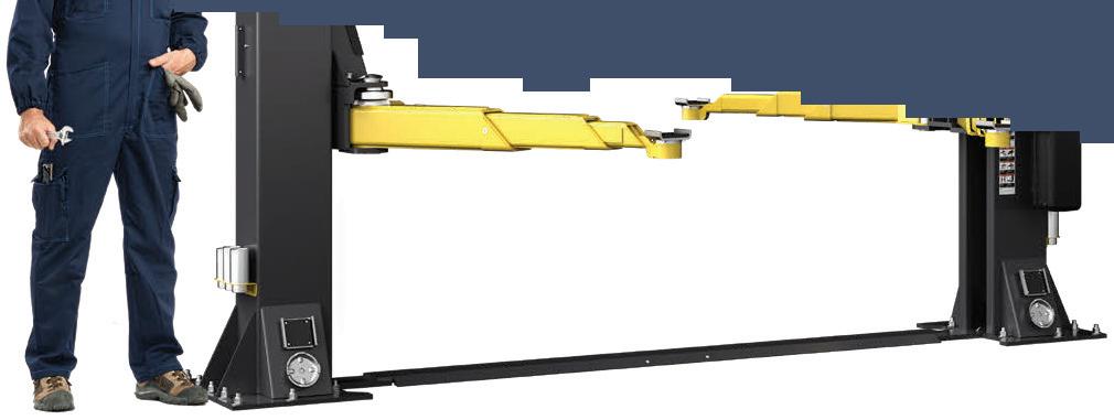


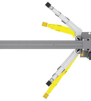


The BendPak 12AP-SRT short-rise two-post lift cost-effectively improves tire shop productivity and efficiency while mitigating risk. With 12,000 pounds rated capacity, massive wingspan that reaches most OEM lifting points, and BI-METRIC™ arms to suit virtually every vehicle lifting requirement – symmetric or asymmetric. The 12AP-SRT can raise 99 percent of cars, SUVs, and trucks to a comfortable working height much faster (and easier) than a set of jacks. Its single-point safety lock system, super-strong automatic arm restraints, and limited max lifting height of 47 inches deliver superior peace of mind. The short 93.5inch columns offer lower product, installation, and maintenance costs, plus a cleaner floorplan. Check out the full line of BendPak lifts at bendpak.com or call us at 1-800-253-2363. Model: 12AP-SRT


S A R S AUTOMATIC SWING ARM RESTRAINT SYSTEM

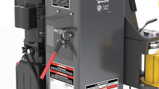
BI-METRIC™ SWING ARMS TRIPLE-TELESCOPING INNOVATIVE SAFETY LOCK
NO. 163 System and Component Performance Evaluation: Variable Reluctance (VR) Sensors
BY BRANDON STECKLER // Technical Editor
Technical Editor Brandon Steckler is back with part 4 of his The Trainer mini-series. This one is called “System and Component Performance Evaluation of Variable Reluctance (VR) Sensors.” We’re following true to the essence of the all-encompassing physical laws. That is, Faraday’s law of electromagnetic induction states that a voltage is induced in a conductor whenever there is relative motion between the conductor and an externally applied magnetic field.
VR sensors have been leveraged in the automotive industry for decades. These simple devices can be seen under the hood as:
• CKP sensors
• CMP sensors
• Wheel speed sensors
• Vehicle speed sensors
• A/C compressor speed sensors
With that, understanding their construction, application, functionality, and configuration is beneficial when it comes to diagnosis as they are the basis for the operation of many systems on vehicles made by virtually every manufacturer out there!
Stick with Brandon as he walks you through how to properly research the wiring diagram, select the appropriate terminals for testing, implement the lab
scope, determine what the waveform means, and (most importantly) how to discover and capture the elusive intermittent faults with the VR sensor-based systems, when they surface.
Learn how rotational speed, circuit resistance and air gap all play a role in waveform exhibition. Discover for yourself how the ECU monitors this signal and uses its frequency to equate to rotational speed.
This episode complements the previous three very well. Look for those videos, on DC motors, solenoids, and relays, and this video, too, on the Motor Age YouTube channel.


FOLLOW MOTOR AGE MAGAZINE ON YOUTUBE TO SEE NEW VIDEOS AS THEY ARE RELEASED.