Dorman OE FIX TM parts are designed to improve reliability or simplify service. Learn more on the inside cover.

Including patented OE FIX™ oil filter adapters for Pentastar engines and much more.
TM
Industry-Leading Coverage, Available Fast ADVERTISEMENT VehicleServicePros.com JUNE 2024
Dorman OE FIX
parts are designed to improve reliability or simplify service.
AutoZone and Dorman put repair professionals and vehicle owners first. Whenever an OEM doesn’t offer the service solution you deserve, Dorman develops a better solution—an OE FIX™ solution.
AutoZone® carries thousands of Dorman OE FIX™ parts that come in countless varieties, featuring:
Upgraded materials to increase reliability
Time-saving designs, such as multi-piece and flexible features, separately serviceable components, etc
Smarter electronics, featuring plug-and-play modules, included programmer tools, faster processors, etc
Serviceable components to simplify future maintenance
Including patented OE FIX™ oil filter adapters for oil filter for Pentastar engines with Pentastar with upgraded aluminum designs aluminum


Scan to
more
DormanProducts.com/AZ TM
©2024 AutoZone, Inc./Dorman Products, Inc. All Rights reserved. AutoZone and AutoZone & Design are registered marks of AutoZone IP LLC or one of its affiliates. Dorman & Design, D Design, OE FIX, and OE FIX & Design are trademarks of Dorman Products, Inc. or one of its affiliates. All other marks are property of their respective owners. Expanded Availability, Delivered Fast
learn
or visit
TM


DIAGNOSING FROM DIFFERENT ANGLES


VehicleServicePros.com JUNE 2024 THREADED FASTENER TORQUE PAGE 16 TRANSMISSIONS AND GEARBOXES PAGE 38 STUMPED BY THE PUMP PAGE 34 A conclusive test result is like a home run, but multiple test results that tell the same story, that’s more like a grand slam. PAGE 10


STARTERS
4 Online Extras
6 Straight Talk
8 Tech Tips TECHNICAL
10 Diagnosing From Different Angles
A conclusive test result is like a home run, but multiple test results that tell the same story, that’s more like a grand slam. Brandon Steckler
16 Threaded Fastener Torque Tips on threaded fastener tightening Mike Mavrigian
26 Toyota Dynamic Force Engines New designs innovate and offer increased efficiency and lower emissions. Jeff Taylor
34 Stumped by the Pump
The heart of the high-pressure GDI fuel system is the HP fuel pump. But it relies on the camshaft to function.
Brandon Steckler
38 Transmissions and Gearboxes What’s changed with HEV, PHEV and EV?
Craig Van Batenburg
58 The Trainer #149 The GateKeeper

Motor Age is published 6 times yearly (February, April, June, August, October, December) by Endeavor Business Media, LLC.

Brandon Steckler TOOLBOX
47 Automotive Product Guide
53 Technical Service Bulletins
56 Ad Index
toll-free at 877-382-9187 or at MotorAge@omeda.com for magazine subscription assistance or questions. Printed in the USA. Copyright 2024 Endeavor Business Media, LLC. All rights reserved. No part of this publication may be reproduced or transmitted in any form or by any means, electronic or mechanical, including photocopies, recordings, or any information storage or retrieval system without permission from the publisher. Endeavor Business Media, LLC does not assume and hereby disclaims any liability to any person or company for any loss or damage caused by errors or omissions in the material herein, regardless of whether such errors result from negligence, accident, or any other cause whatsoever. The views and opinions in the articles herein are not to be taken as official expressions of the publishers, unless so stated. The publishers do not warrant either expressly or by implication, the factual accuracy of the articles herein, nor do they so warrant any views or opinions by the authors of said articles.
Endeavor Business Media provides certain customer contact data (such as customers’ names, addresses, phone numbers, and e-mail addresses) to third parties who wish to promote relevant products, services, and other opportunities that may be of interest to you. If you do not want Endeavor Business Media to make your contact information available to third parties for marketing purposes, simply call toll-free 877382-9187 or email MotorAge@omeda.com and a customer service representative will assist you in removing your name from Endeavor Business Media’s lists. Motor Age does not verify any claims or other information appearing in any of the
and
for any losses or other damages incurred by readers in reliance of such content. While every precaution is taken to ensure the
and the
waives all responsibility for errors and omissions AD DEADLINES: Insertion orders–1st of month preceding issue
VEHICLESERVICEPROS.COM 3 MOTOR AGE 10 16 38 26 CONTENTS June 2024 / Vol. 143 #3
201
Fort Atkinson, WI 53538.
service
N Main St 5th Floor,
Customer
can be reached
publication,
correctness
guaranteed,
issue date.
advertisements contained in the
cannot take responsibility
accuracy of the ad index, its
cannot be
publisher
date. Ad materials–5th of month preceding
ONLINE
TALK SHOP. ANYTIME.
TIS THE SEASON

We know automotive puzzles don’t begin and end in a single edition of Motor Age. (Heck, we’ve been at this 125 years and there are still plenty more puzzles to solve!) That’s why we publish exclusive technical content every day online. Have you noticed an uptick in A/C work as the summer heat settles in? Chemours provided a two-part series on the ins and outs of what technicians need to know about R-1234yf refrigerant. Find that and more timely help on vehicleservicepros.com.

SCAN TO SEE OUR FULL MENU OF VIDEO CONTENT
POPULAR

TECH CORNER
Follow along as real-world technicians present perplexing repair stories. Wrench Tales is the latest video project of Motor Age Technical Editor Brandon Steckler. Every month he walks alongside another technician who shares a troublesome repair job, and the diagnostic steps that ultimately led to the fix.
EDITORIAL
GROUP EDITORIAL DIRECTOR
Matt Hudson / mhudson@endeavorb2b.com
EDITOR
Mike Mavrigian / mmavrigian@endeavorb2b.com
MANAGING EDITOR
Joy Kopcha / jkopcha@endeavorb2b.com
TECHNICAL EDITOR
Brandon Steckler / bsteckler@endeavorb2b.com
ASSOCIATE EDITOR
Madison Gehring / mgehring@endeavorb2b.com
CONTRIBUTING WRITERS
Jeff Taylor, Craig Van Batenburg
ART AND PRODUCTION
ART DIRECTOR
Rhonda Cousin
PRODUCTION MANAGER
Mariah Straub
AD SERVICES MANAGER
Melissa Meng
SALES
ASSOCIATE SALES DIRECTOR
Mattie Gorman-Greuel / mgorman@endeavorb2b.com
DIRECTOR OF BUSINESS DEVELOPMENT
Cortni Jones / cjones@endeavorb2b.com
ACCOUNT EXECUTIVES
Kyle Shaw / kshaw@endeavorb2b.com
Marianne Dyal / mdyal@endeavorb2b.com
Martha Severson / mseverson@endeavorb2b.com
Darrell Bruggink / dbruggink@endeavorb2b.com
Sean Thornton / sthornton@endeavorb2b.com
Diane Braden / dbraden@endeavorb2b.com
Lisa Mend / lmend@endeavorb2b.com
Chad Hjellming / chjellming@endeavorb2b.com
ENDEAVOR BUSINESS MEDIA, LLC
CEO
Chris Ferrell
PRESIDENT
June Griffin
COO
Patrick Rains
CRO
Paul Andrews
CHIEF DIGITAL OFFICER
Jacquie Niemiec
CHIEF ADMINISTRATIVE AND LEGAL OFFICER
Tracy Kane
EVP TRANSPORTATION
Kylie Hirko
BUSINESS STAFF
VP/MARKET LEADER - VEHICLE REPAIR GROUP
Chris Messer
ASSOCIATE PUBLISHER
Andrew Johnson
BUSINESS DEVELOPMENT DIRECTOR,
MOTOR AGE TRAINING
Michael Willins
CUSTOMER MARKETING MANAGER
Leslie Brown
AUDIENCE DEVELOPMENT MANAGER
Tracy Skallman
SALES COORDINATOR
Jillene Williams
HOW TO REACH US
ENDEAVOR BUSINESS MEDIA LLC.
30 Burton Hills Blvd, Ste. 185, Nashville, TN 37215
Phone: 800-547-7377
CUSTOMER SERVICE
Subscription Customer Service 877-382-9187; 847-559-7598

The best way to ensure you never miss a technical tip or in-depth article from Motor Age is to subscribe to our weekly and monthly newsletters and follow us on social media. We hang out on LinkedIn, Facebook, and Instagram, and post all of our exclusive video content on YouTube as Technical Editor Brandon Steckler walks you through any number of diagnostic dilemmas.
MotorAge@omeda.com
PO Box 3257 Northbrook, IL 60065-3257
REPRINT SERVICES reprints@endeavorb2b.com
MEMBER OF:

VEHICLESERVICEPROS.COM 4 JUNE 2024 CELEBRATING 125 YEARS ON THE WEB
EXCLUSIVE FOLLOW
ALONG


©2024 Stellantis Auto SAS. All Rights Reserved. bproauto is a registered trademark of Stellantis Auto SAS. The bproauto® aftermarket brake family is of the highest pedigree of stopping power. They are engineered and crafted to O.E. specifications; they fit, work and last; are warranty backed; and are competitively priced. Get to know them at bproautoparts.com. Over 40 part types. Over 20,000 part numbers. bproauto® brakes. Affordable quality built to fit, work and last. Search our catalog at bproautoparts.com Disc brake pads Disc brake rotors Brake drums Drum brake shoes Parking brake shoes Disc brake rotor and hub assembly Disc brake calipers Meet the bproauto brakes family: The nucleus of your braking system, from our family of brake parts.
Lights, Camera, Action
A walk-around video can save you from erroneous claims.
WHILE THIS HOPEFULLY IS A RARE ISSUE,
there is the potential wherein a customer claims that his or her vehicle was “damaged” while at your shop. This might involve a dent, body paint scratches, interior stains, cracked windshield, scuffed alloy wheels, etc. Granted, mishaps can occur during a busy and frantic workday, and the majority of repair shops routinely handle their customers’ vehicles with the utmost care. But the potential for such a claim is nevertheless real.
In order to protect yourself from such claims, consider performing a simple walk-around of the vehicle when it enters the shop and record it using a smart phone or a digital camera. Slowly walk around the entire vehicle while video recording the front, driver side, rear and passenger side. Open a door and record the interior (front and rear). Of course, you can go further by taking video or still photos of the engine bay and undercar areas if you like.
Sadly, in some cases, a less-thanhonest customer may try to pin (i.e. scam) damage on you in a misguided effort to glean a free repair of damage he or she knew existed before arriving at your shop. In other cases, an honest but perhaps inattentive customer may not be aware of the damage, but notices it when picking the vehicle up after the requested repairs.
Of course, if the damage was indeed caused while the vehicle was in your shop’s possession, you’re liable for it and should see to it that the appropriate repairs are handled. Hopefully your
garage keeper’s insurance will cover that. But when an irate customer rants and screams, you’re in a tough spot. In this day and age, we know all too well that one disgruntled customer is able to post their complaints via social media, and naturally that’s something we want to avoid. Being able to show the video or photos can prove that the issue(s) existed when the vehicle arrived.
I recently visited a local Ford dealership and observed a service advisor taking a brief video of each and every vehicle the moment it was pulled into the shop. This was downloaded to the shop’s computer to serve as a per-customer record. Out of curiosity, I asked about the practice and was told they had encountered a few such scam attempts in the past, and had since decided to video every vehicle as a matter of routine.
Tool Organization
How many of us are guilty of tossing our hand tools back into the tool chest after completing a rush job and moving on to the next project? Probably more than we would like to admit.
A disorganized toolbox is one of my pet peeves. We waste time when we search through a messy drawer trying to find that 10mm deep-well socket or that short, stubby screwdriver that we know is the only one that will fit a certain task. Keeping all of our metric socket wrenches and combo wrenches in one drawer, and organized on graduated trays not only creates a professional appearance, it allows quick access to the size/ type needed at a moment’s notice. The
same goes for inch format wrenches, brake system specialty tools, make hex bits, ratchets, torque wrenches, etc.
Our tools are not only necessities — without which we couldn’t open the shop doors — they’re our buddies. They’re the cohorts to our daily work, and the muses to our skills, ambitions and goals to do the best we can on every job. They deserve to be treated with respect.
While it’s often difficult to maintain your tools during a hectic workday, set aside a few minutes at the end of the day — or at least at the end of each week — to not only organize all of the tools in your chest, but clean them as well. Starting the day off with your tools neatly placed and clean is akin to the first coffee of the day — it just makes you feel better.


 MIKE MAVRIGIAN MOTOR AGE // EDITOR mmavrigian@endeavorb2b.com


STRAIGHT TALK VEHICLESERVICEPROS.COM 6 JUNE 2024


Rack up Rewards
Select Genuine Nissan and Value Advantage® rotors, pads, drums, shoes, shocks, struts, steering racks and pumps. Earn 10% back with Parts Rewards1 Qualifying enrollees are also eligible to earn up to 3% back2 on a wide range of select Genuine Nissan and Value Advantage® mechanical parts. There is no cost or purchase obligation to participate. Sign up at NissanUSAPartsRewards.com ¹Participating Parts Rewards Enrollees may be eligible to earn an additional 10% in Parts Rewards for each qualifying part: select Genuine Nissan and Value Advantage® rotors/pads, drums/shoes, shocks, struts, steering racks and pumps sold during the promotional period April 1, 2024 – June 30, 2024. ²Based on Independent Repair Facility’s purchases from your local authorized dealership. IRF must be enrolled In the Parts Rewards program to be eligible. Available to one qualified repair facility employee per IRF. For official program rules and eligibility, see “Terms and Conditions” at NissanUSAPartsRewards.com. Program Rules are subject to change at any time and/or program offer is subject to termination without notice. The Nissan names, logos and slogans are trademarks owned by or licensed to Nissan Motor Co. Ltd. and/or its North American subsidiaries. Always wear your seat belt and please don’t drink and drive. ©2024 Nissan North America, Inc. All rights reserved.
Around the Wheel
Complete
Steering
Rear Shocks Brake Rotors & Brake Pads
Strut Assemblies
Pumps & Steering Racks
Stubborn Fasteners
We’ve all been there — you encounter a bolt, nut or threaded plug that argues with you and is stuck in place due to corrosion, excess torque, etc. One trick that sometimes works is to apply a bit of tightening, followed by an attempt at loosening. This may be repeatable several times (tighten, loosen, tighten, loosen, etc.). This can dislodge the corrosion that is creating the stubborn removal.
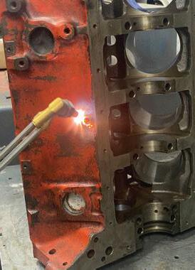
A commonly effective method to loosen and remove a stubborn threaded plug is to first heat the plug area with a concentrated source of heat using a torch. Heat it until the plug and immediate adjacent area is cherry red. At this point, apply a stick of pure wax. The wax liquifies and enters the threaded area that has expanded as a result of the concentrated heat. This is often a successful method, and is especially effective for threaded plugs that seal oil or water ports.
Sometimes applying a thread penetrant and allowing it to soak for hours does the job. Other times, you may get frustrated to the point where you resort to grinding off the head, center-drilling the exposed shank and attempting to remove the bolt shank using an easy-out tool, likely followed by running a cleaning tap to restore female threads. Depending on the location of the bolt, you might opt to break out the torch, heating it to cherry red (which expands the metal and breaks down corrosion or serious
threadlocker. Obviously there are various grades of threadlocker compounds from medium to high strength. When a medium strength threadlocker, such as Loctite 242, is applied and cured, this usually doesn’t create an issue, as reverse torque will generally overcome the locking strength of the compound. When a high strength locking product — Loctite 271, for example — is used, the only way to break the bond is to apply heat to the fastener, which quickly liquifies the bond.


Of course, using a torch isn’t always an option due to the obvious risk of starting a fire or damaging other nearby components. Enter the heat induction tool.
Induction bolt heaters utilize flame-free electromagnetic waves to induce heat into the errant bolt or nut, heating the object to about 500 degrees (or more, depending on the specific tool) resulting in cherry red heat soak within a limited space of 60 seconds or less. By placing the tool’s circular coil over the bolt or nut, the quickly-obtained and very isolated heat expands the surround metal, allowing easy removal of a stuck/corroded/galled bolt without resorting to the use of a torch. This has obvious benefits in on-vehicle situations where using a torch can result in a fire and/or damage to surrounding areas.
These tools utilize eddy currents, operating on AC power. A coil at the tip
of the tool is made of copper or another conductive material. The coil is placed over or close to the bolt (not actually contacting the bolt). When the AC current flows though the coil, it generates an electromagnetic field. The resistance of the bolt’s material causes it to rapidly heat. As the bolt quickly reaches the desired temperature, it expands, breaking any rust/corrosion bonds.
Heat induction tools are available in variations from affordable to expensive. For general automotive applications, these tools are available at prices ranging from about $180 to $500. These tools can save the day, making it easy to quickly remove seized fasteners without the use of brute force and/or being exposed to a fire hazard.
You may or may not need to deal with stainless steel fasteners (bolts, nut or studs). When installing a stainless steel threaded fastener into a steel threaded hole, be aware that you can accidentally create a thread galling issue if you install the fastener too fast. The frictional heat can result in metal transfer and galling, making final torquing and/or fastener removal extremely difficult. First applying a thin coat of an anti-seize paste or appropriate locking compound will serve as a lubricant to avoid this potential issue.
8 JUNE 2024
Chevy DPF Issue
2010 and newer Chevy light trucks equipped with a diesel engine may exhibit black smoke at the tailpipe and DTCs P2002, P226D and/or P244A may be set in the ECM. Chances are, the DPF filter has an issue. The DPF differential sensor lines may be blocked or disconnected, preventing the filter from performing its job properly.
A properly functioning diesel particulate filter should remove most if not all soot particles from the exhaust stream. The following test should not be performed immediately after a regeneration because of the reduced filtration efficiency of the DPF without any soot in it. The purpose of this test is to aid in diagnosing a DPF that has failed internally. Hold a cheesecloth or equivalent across the tailpipe opening. Have an assistant rev the engine to the rev limiter and back to idle. Repeat this a total of eight times.
A failed test will show excessive soot particulates on the cheesecloth. These soot particles indicate that the exhaust particulate filter is no longer able to capture all of the soot particles and should be replaced. A passing test will show no, or very minimal signs, of soot particles.
Corvette Warbles
If you encounter a 2014-2019 Corvette equipped with a 6.2L engine and 8L90 automatic transmission that exhibits a “warble” noise at about 1,500 rpm, this may be due to the bushing in the left side differential cover having too much clearance. The correction involves replacing the left side rear axle housing cover, using cover P/N 84705711 and nut P/N 11612295. Note: this does not apply if the vehicle is equipped with an electronic positraction/limited slip differential.
Audi Power Loss
If you encounter a 2013-2014 Audi equipped with a 2.0 TFSI engine and the concern involves a notable power drop, check to see if the circlip connecting the turbo wastegate actuator rod and the wastegate flap level has fallen off. If the clip is gone, the wastegate linkage will disconnect, which results in loss of turbo boost.
Prep for Perfection.


FROGTAPE ® PERFORMANCE MASKING TAPES
Engineered for challenging marine, automotive, transportation and other applications where industrial coatings are applied. The only thing they won’t mask is your craftsmanship.


9 MOTOR AGE VEHICLESERVICEPROS.COM DOES NOT contain PaintBlock® Technology Visit FrogTape.com/ Performance ©Shurtape Technologies, LLC 2024/ASW00736
® 2406MA_ShurtapeTechnologies.indd 1 5/6/24 8:51 AM
Diagnosing From

A conclusive test result is like a home run, but multiple test results that tell the same story, that’s more like a grand slam.
BY BRANDON STECKLER
DIAGNOSTIC STRATEGIES 10 JUNE 2024
137913561 OPZ CREATIVE DREAMSTIME.COM
Different Angles

I’ll be the first to tell you that being a technician under pressure to get the job done quickly is not a stressfree position. This intensity is multiplied tenfold when you factor in the flat-rate pay scale for a technician (a concept I disagree with wholeheartedly). With that, many will jump at the opportunity to draw a diagnosis from a single piece of data that coorelates with an exhibited symptom. However, I urge you to step back and revisit the vehicle from a different angle.
Stepping Stones
As I’ve mentioned many times before in previous articles, I always choose to take the diagnostic path that yields me the most information for the least amount of time or energy invested. I joke about this as my being inherently lazy. But the truth is it’s just more logical and efficient to conduct testing in this manner. After all, we don’t necessarily do this job as a hobby. I mean, we may love it (heck, I think you must love it to be any good at it) but we do it to be profitable. Although profitability likely interests everyone, it’s the increase in accuracy that this logical approach to testing brings to the table that motivates me. The profitability follows naturally.
This is best discussed by way of example. Assume a vehicle was towed into the shop with a dead battery. Some may choose to conduct a capacitance test with the devices we typically implement at a multi-point service check (Figure 1). A failure would be a reason for most technicians to replace the battery. I agree with that approach, but we can’t stop there. There are still a few unanswered questions that must be pursued. The goal? To not fix the symptom but to fix the root cause of that symptom. In plain English, what caused the dead battery? Below are just a few questions that come to mind:
• Is the battery just old and expired?
• Is there a parasitic drain present, killing the battery?
• Is the alternator charging properly?
• If not, why? Is there a voltage drop elsewhere in the battery charging circuit?
Eliminating those above possibilities in logical order would mean beginning with the easiest test and concluding with the most difficult or most time-consuming test. That is, of course, if the customer approves the diagnostic time.
Although this is just a quick example of what I’m trying to portray, let’s follow through with an actual case study.
VEHICLESERVICEPROS.COM 11 MOTOR AGE
FIGURE 1: A CAPACITANCE tester is commonly used to quickly evaluate the condition of a battery. However, I have witnessed many pass a failed battery. Capacitance is simply one characteristic of a battery’s performance.
You’ll see, had the tech not pursued the root cause of the issue, a lot of money and heartache would’ve been invested.
Initial Approach
A vehicle was brought into the workshop with the complaint of “MIL illuminated.” Upon retrieving the vehicle and preliminary evaluation with the scan tool, the technician discovered a DTC, P0304-cylinder No. 4 misfire was set in history (Figure 2).
A road test of the vehicle was conducted, and the engine was run throughout the entire operating range. The technician did note some slight misfire/ driveability concerns exhibited mostly during idle conditions. Considering she is still in the driver’s seat, the tech thought it best to monitor the fuel trim activity as it is a clear reflection of combustion quality or lack thereof, as well as an indicator of what type of misfire may be exhibited (like an ignition fault, an injection fault, or an engine mechanical fault) (Figure 3).
The misfire was felt at the time the fuel trim was monitored and the lack of compensation allowed the technician to determine the fault was unlikely to be from the ignition system or the fueling system. This put an engine mechanical concern at the top of the list of suspected root-cause faults. Again, all from the driver’s seat.
The PCM’s misfire data was then monitored to determine if cylinder No. 4 may be the cylinder responsible for the driveability fault (Figure 4). The data PIDs concur that cylinder No. 4 is registering misfires. Although misfire detection software is much more reliable than in years past, it is not foolproof. Misfire data is just another piece of the diagnostic puzzle.
A relative compression test was conducted, and the results did not reflect a significant loss of compression (Figure 5). Although this seems contradictory to an engine mechanical fault diagnosis, we must keep in mind that a loss in compression isn’t always the result of an engine mechanical fault. The relative


DIAGNOSTIC STRATEGIES 12 JUNE 2024
BRANDON STECKLER
FIGURE 4: MISFIRE DATA can help determine when a misfire is present and for which cylinder is responsible. This is especially tactful when a correlating misfire DTC is not present.
BRANDON STECKLER
FIGURE 3: MONITORING FUEL trim during a misfire is a great way to preliminarily determine the type of misfire being exhibited. Each type of misfire (spark, fuel, engine-mechanical) will generate a different fuel trim response. An engine mechanical fault doesn’t typically cause a large shift in fuel trim compensation.
118949963 DUH84BK DREAMSTIME.COM
FIGURE 2: PRELIMINARY DATA like a DTC scan can help determine where to begin a diagnosis, but should only be used as a piece of the diagnostic puzzle.


compression test is limited to only indicating if and how well the cylinder can harness and squeeze its contents.
Generalized Testing
As the technician eventually made her way beneath the hood to continue her diagnostic path, she noted an alarming, rhythmic noise resonating from within the engine compartment. This raised a few questions:
• Could the noise be from cylinder No. 4?
• Could the noise be related to the misfire?
• Could the noise be a different problem altogether?
• How can we determine where the noise originates?
The above questions are indeed very logical, and I urge you as technicians to consistently question yourself as you proceed through an analysis. The questions you ask should determine the tests you follow up with. The test results should answer the questions.
Implementing the mechanic’s stethoscope will allow her to pinpoint the noise with relative ease and help her decide how to proceed (Figure 6). Again, the takeaway is the test being performed is a bit more involved than just sitting in the driver’s seat with the scan tool, but it was justified as time well spent and it will definitely bring her closer to a conclusive diagnosis.
The engine noise was analyzed with the stethoscope from beneath the hood and the noise was loudest at the cylinder head area of cylinder No. 4. This answers one of the above questions. However, it doesn’t necessarily indicate if the noise is from the valve train or the piston and rod assembly of cylinder No. 4.
The tech then chose to implement a pulse sensor and oscilloscope. The same stethoscope was used to locate the noise, however, instead of pumping information into the tech’s ear, the stethoscope was connected to the pulse sensor. The intensity of the generated pulse signal will correlate with the noise occurrence and location. The pulse was not only visible
VEHICLESERVICEPROS.COM 13 MOTOR AGE
BRANDON STECKLER
FIGURE 5: A RELATIVE compression test is a quick and easy way to determine engine/cylinder integrity.
226119431 | ARKADIY LUCHAK | DREAMSTIME.COM
FIGURE 6: THE STETHOSCOPE is a great tool to help pinpoint the source of an engine noise.
A pulse sensor in combination with a stethoscope and coupling it to an oscilloscope can offer a visual representation of the noise we hear. This can be correlated with different data (like an in-cylinder compression waveform) to help determine the source of the noise, its frequency and specific events occurring. This capture from an unrelated vehicle demonstrates a worn and noisy exhaust valve rocker/cam lobe. BRIN KLINE TRAINED BY TECHS
FIGURE 7: USING
but indicated the noise occurred twice per engine cycle (Figure 7). This puts a valve train noise at the bottom of the list of root causes since the camshaft turns once per engine cycle.
The vehicle was hoisted to allow access to the bottom-end area and noise was obvious in this area of cylinder No. 4 as well, and equally as intense. The results of this test corroborate the noise is not likely to be in the valve train but internal to the engine block.
Pinpointed Testing
Considering the questions above, if we could temporarily eliminate the cause of the misfire, we could find an answer to all of them simultaneously. Considering this vehicle’s configuration, access to the COP ignition coils is easily obtained (Figure 8).
As the engine idled and the noise was exhibited, the COP of the suspect cylinder No. 4 was disabled. By unplugging the coil, a consistent misfire would definitely occur, but the bigger takeaway is since no combustion is taking place, the noise also vanished. What’s the point? The noise is not likely to be between the crankshaft journal and the main bearing cap. Meaning, that the noise is likely between the No. 4 piston
and wrist pin or the connecting rod bearing and crankshaft journal. The cost of repair will vary depending on which fault is present. All the questions above can be answered if we take the analysis just a little bit further. With that another set of questions comes to mind:
• Can we determine the engine-mechanical fault without disassembly?
• What test result may help draw that conclusion?
Some logical thinking is required to answer these questions but there is a test that may help put the final nail in the coffin and deliver a diagnosis we can be confident in speaking about with the customer. Because low-end engine noise is present, we do have to consider the collateral damage that may be taking place. Again, the idea is to give the customer the most accurate diagnosis possible so he or she can make a sound decision about whether the repair of this fault is right for them financially.
Keeping the trend of analysis without disassembly is the theme of this article. By placing that same pulse sensor on the dipstick tube, the tech obtained data that accurately depicts the conditions within the crankcase of the engine. She cranked

THE NEXT TIME YOU FACE MAKING A TOUGH CALL ABOUT SOMETHING AS EXPENSIVE AS AN INTERNAL ENGINE MECHANICAL FAILURE, DON’T PANIC, AND DON’T GUESS.”
the engine over several cycles and a pattern was noticed. The pattern indicated an increase in crankcase pressure once per engine cycle.
With some research of the firing order and adding an ignition sync on a second channel of the scope, the tech was able to correlate the rise in crankcase pressure with the top-dead-center (TDC) of cylinder No. 4, our suspect cylinder (Figure 9). This is an indicator that the surface between the piston assembly and the cylinder walls has been compromised. This one piece of data prevented the attempt at repair that could have been a lot of money and time invested without even addressing the collateral damage created by the engine noise we would be attempting to rectify. This would certainly be a bad day for the technician, the shop, and the customer.
This final piece of data allows her to approach her service advisor and alert the customer of the bad news — or is it really good news? Regardless of whether the engine mechanical fault is contributing to the misfire, the cost of repair makes engine replacement the only logical option.
DIAGNOSTIC STRATEGIES 14 JUNE 2024
137528342 DMITRY BACHTUB | DREAMSTIME.COM
FIGURE 8: IN MANY engine configurations the COP coil is utilized. Easily accessible, disabling the COP is a great way to eliminate combustion/contribution from a cylinder in what we know as a balance test.


This customer must decide whether to get rid of the vehicle or invest in the replacement of the engine.
The takeaway from this case study is that all of this was obtained from data that is easily accessible, takes minutes to obtain, and requires no disassembly whatsoever. The technician got paid handsomely for honest testing that gave the customer a pinpoint engine-internal fault diagnosis without the associated cost of traditional disassembly/inspection. Although that would be the next step, the customer is aware and will be able to anticipate what is to be found upon disassembly and inspection, and that is worth something.
The next time you face making a tough call about something as expensive as an internal engine mechanical failure, don’t panic, and don’t guess. Implement multiple tests in a logical succession and you will find yourself placing multiple arrows in the same target. This will increase your level of accuracy many times over, decrease your applied diagnostic time by minimizing disassembly, and establish confidence in yourself that makes your job as a technician very rewarding.
That’s something we should all be proud of.

SCAN TO READ MORE ARTICLES FROM BRANDON STECKLER.

Delphi is driven to apply its OE expertise and technological leadership to engineer each fuel module with stringent standards that deliver the highest level of performance.
With over 85,000+ applications, you can install Delphi parts with confidence.


15 MOTOR AGE VEHICLESERVICEPROS.COM
A Leader in Fuel Management delphiaermarket.com Trust us to be your partner in repairs — be Delphi Driven. 2406MA_DelphiTechnologies.indd 1 5/10/24 1:02 PM
BRANDON STECKLER
FIGURE 9: THIS RHYTHMIC pulse in the crankcase indicates blow-by of one cylinder. A very expensive fault to repair. This was obtained by measuring pressure changes at the dipstick tube and correlating them with an ignition sync. It required no disassembly whatsoever. This is an unrelated vehicle with an 8-cylinder engine.
BRANDON STECKLER is the technical editor of Motor Age magazine. He holds multiple ASE certifications. He is an active instructor and provides telephone and live technical support, as well as private training, for technicians all across the world.


Tips on threaded fastener tightening
BY MIKE MAVRIGIAN
PROPERLY TIGHTENING VARIOUS threaded fasteners requires adhering to specified torque values and/or torque-plus angle for the application at hand. Understanding proper use of a torque wrench is important in order to obtain the clamping loads needed for any given application.
A torque wrench is a precision tool that allows you to monitor and reach a specific torque value (rotational force) when tightening a threaded fastener. Variations and different models of torque wrenches are designed to monitor torque value in foot-pounds (ft-lb), inch-pounds (in-lb),


Threaded Fastener Torque
and/or Newton meters (Nm), mKg (meter kilograms) or centimeter kilograms (cmKg). Versions are available that handle all English and metric scales, as well as versions dedicated to either format.
Terminology
While it’s common for either term to be used, strictly speaking, when discussing rotational torque value applied to turn a threaded fastener, the term “foot pound” (ft-lb) is correct. Pound-foot (lb-ft), on the other hand, is a unit of work. In automotive applications, pound-foot refers to the amount of torque produced by an engine (the work done by one pound of force acting through


a distance of one foot per second). While the two terms refer to two distinct applications, we often take the liberty of using either term when discussing torque value.
Types of Torque Wrenches
Currently there are four basic types of torque wrenches commonly used for automotive applications. These include the beam-type (a mechanical needle sweeps through a printed scale); the dial indicator that features a round gauge; micrometer style that features an adjustment scale at the tool handle and provides a “click” when the selected value is reached; and modern digital types.
As precision tools evolve, we now have access to battery-powered digital torque

IF YOU insist on using an impact wrench to tighten, take advantage of torque sticks. These are available in all common hex sizes and in common torque value ranges. When the designed torque is achieved, the beam twists, removing the rotational force. When the fastener stops turning, stop. Do not continue to dwell the wrench.

16 JUNE 2024 THREADED FASTENERS
TODAY’S ELECTRONIC digital torque wrenches offer ease of use in addition to superb accuracy. Depending on the specific model, you can easily switch formats between ft-lb, in-lb, Nm, mKg and cmKg. Versions are offered in 1/4-inch drive, 1/2-inch drive and 3/4-inch drive.

wrenches that offer distinct advantages in terms of ease of use and versatility. The desired torque value is selected by pushing a button to scroll to the desired value. Digital wrenches that offer both ft-lb and in-lb as well as metric values allow switching from English to metric modes. Depending on the model, when the selected value is reached, the tool provides an audible (beep) or vibration alert or a combination of both alerts.
Torque Wrench Tips
When you’re finished with the wrench, don’t blindly place it back in your tool chest. Before storing, any mechanically adjustable micrometer “click” type


ratcheting torque wrench should always be set to the lowest value prior to tool storage. If you leave the wrench at it’s previously-used high-torque setting, this can allow the internal spring inside the tool to “set,” which will result in potential calibration issues. When you’re done with torquing, adjust the wrench to the low (zero) setting before placing the wrench back in your tool chest. This removes stress and relaxes the internal mechanism.
Keep in mind that all torque wrenches are precision instruments, so handling and care is important. Avoid using a torque wrench as an “every day” wrench

— only use it when tightening a fastener to a specified value.
When tightening a fastener using a torque wrench, take care to avoid tightening past the release point/specified value. Do not operate the torque wrench in a fast manner — use a smooth and steady pull and avoid any jerking motion. Smooth and deliberate movement is necessary to most precisely achieve the desired value.
If you are using a flex bar or dial indicator type torque wrench, use care to monitor/read the pointer or dial indicator needle 90-degrees to the working surface (allowing for a “straight-on” view). If you

17 MOTOR AGE VEHICLESERVICEPROS.COM
5
PHOTO BY MIKE MAVRIGIAN
WITH THE press of the mode button, the same wrench is instantly switched to in-lb (inch pounds).
SOME MORE sophisticated electronic torque wrenches allow you to achieve both torque value (ft-lb shown here) and the ability to perform angle tightening when desired.
TORQUE WRENCHES are available in various overall lengths. For addressing high torque levels, a longer torque wrench offers added leverage, reducing operator effort.
try to view the indicator at an angle, this can easily result in misreading the value. Here’s another tip: Not all micrometer ratcheting style torque wrenches are designed to be operated in both right or left (clockwise or counterclockwise) directions. Granted, while a beam type wrench can be used in right or left turn operation, the internal design of micrometer ratcheting style torque wrenches may be designed for right-turn only or right/left bidirectional operation. If the wrench is designed for right-turn only operation, applying counterclockwise operation may damage the internals and alter calibration. Torque wrenches that are intended for clockwise use only will likely (and should) feature a warning label indicating this. If a torque wrench becomes dirty, carefully clean by hand. Never immerse a dial or micrometer torque wrench in solvent. Function and calibration will be affected if the internal lubricants are washed away. If a high level of torque is required, the operator obviously needs to apply more effort. In order to make the job easier, you may be tempted to add a “cheater” bar to

the grip of a torque wrench to gain more leverage. Never do this! This will result in potential tool damage, and will result in inaccurate values. If the required effort to tighten a series of bolts to, say 150 ft-lb is difficult for you, you have two options: visit the gym, strengthen your arms and deal with it, or select a longer torque wrench that is more appropriate for the task at hand.
Always keep the torque wrench 90-degrees to the fastener. Avoid the use of socket universal joints, as this will affect the applied torque value.
Do not attempt to use a torque wrench beyond its established adjustment range. For example, if the tool features a maximum of 100 ft-lb, do not try to “guess” by continuing to tighten to a higher value.
Recalibration
Because a torque wrench is a precision instrument that features wear- and stress-sensitive internal parts (the exception being the beam type), you need to be aware that micrometer- and ratcheting-type torque wrenches should be recalibrated from time to time in order to maintain accuracy.
A general rule of thumb is to have recalibration performed every 5,000 to 10,000 cycles. Depending on use, you may consider having this done at least once per year. Since a shop likely has multiple torque wrenches, consider establishing a rotating schedule to avoid being without a


torque wrench at any given point. Recalibration and repair services are available, either from the wrench manufacturer or from independent service locations.
Fastener Elastic Range
Threaded fasteners, especially those responsible for critical applications such as cylinder head, main cap or connecting rod service, slightly stretch when full torque value is applied. This slight stretch helps achieve the required clamping load. Similar in nature to a rubber band, when specified torque is applied, the bolt shank begins to stretch. When the bolt is loosened, the shank returns to its static length. This “elasticity” is critical for the bolt to provide the needed clamping load and to maintain that load. If the bolt is tightened beyond its elastic range, the bolt can enter its yield point and weaken, making it no longer able to provide the necessary load. By the same token, if the bolt is undertightened, and does not enter its elastic range, it won’t provide enough clamping force.
In reality, about 85% of the torque applied during tightening is used to simply overcome friction — friction at the threads and between the underside of the bolt head (or nut) and the parent material of the object being installed. For this reason, it’s important to follow any instructions that call for a specific thread lubricant (in those cases where a lube is required).
• Both male and female threads must be clean and free of burrs.

• When specified, apply the required lubricant to the threads before assembly. This may involve engine oil, molybdenum disulphide, an anti-seize compound, or an anaerobic thread locking compound, depending on the situation. Whenever tightening a thread fastener, avoid excessive tightening speed. Installing or tightening too quickly tends to generate excess friction, which can affect the final value accuracy.
• Avoid jerky motions when using the torque wrench. Use slow and deliberate


THREADED FASTENERS 18
WHEN TIGHTENING with a torque wrench, avoid quick/jerky movements. Use a steady, smooth pull and support the drive head to help keep the socket wrench engagement straight and in line with the fastener.
SHOWN HERE are two examples of torque wrench extensions. Both are 3/8-inch drive. The upper features a 12-point, half-inch box wrench and the lower is a 3/8-inch box wrench. Common sizes in both 6 point and 12 point are available. These extensions allow you to utilize a torque wrench in areas that feature access challenges.
EXAMPLE OF a torque wrench extension in use. Due to the location, this bolt was not accessible from overhead.


motions as you approach the desired value. Tightening too quickly can result in slight overtightening as you continue bolt rotation beyond the “click”or desired torque value.
• Be sure to distribute the clamping load evenly in the specified tightening sequence, being careful to apply an equal level of load to each fastener. This is especially important for critical engine, transmission, suspension and brake components.
Torque Wrench Selection
One torque wrench does not fit all applications. In addition to having access to torque wrenches that apply to ft-lb and in-lb and metric formats, keep in mind you should always use a torque wrench that provides applied values in the middle of the wrench’s calibrated range. By that we mean that the torque wrench should never be used only at or near its adjustment range. For instance, if you need to tighten fasteners to 95 ft-lb, the best selection would not be a wrench that features a limit of 100 ft-lb. A better choice would be a wrench that offers a high range of 250 ft-lb. In general terms, a torque wrench will provide greater accuracy when the target value is somewhere in the middle of its range.
If you need to apply in-lb values, a torque wrench that reads in in-lb is needed. If you only have access to a ft-lb wrench, you may be tempted to adjust the wrench to suit. For instance, if you need 80 in-lb, you might adjust the ft-lb wrench
to 6 or 7 ft-lb, but this will not be accurate.
In many of today’s applications (primarily engine/drivetrain work), you may encounter tightening specifications that call for torque-plus-angle, in which case you need a combination torque wrench that allows you to achieve both specs. These are yet more reasons to maintain a selection of torque wrenches for various ranges of torque values.
Torque Wrench Extension
You may encounter situations where you simply do not have easy access to a bolt head or nut where you cannot attach the torque wrench’s socket wrench. Rather than employing an open or box wrench and tightening by hand and guessing torque value, you may be able to use a torque wrench extension. As opposed to a straight extension that increases the length from the torque wrench head to the fastener, this type of extension increases the overall length of the torque wrench, providing a box wrench for fastener engagement.
While using a torque wrench extension may provide fastener access, be aware that by altering the overall torque wrench length, you now increase leverage, which affects the applied torque value. If you do not compensate for the extension, you will overtighten the fastener. When you add the extension, you must reduce the torque wrench setting to a slightly lower value.
The following is a simple formula to achieve this.
TW = L DIVIDED BY L+E x TE
We then divide 18 by 20 (in this case 0.9).
Multiply this by our desired torque value, so 0.9 times our desired value of 40, which equals 36.
So in this case, in order to achieve 40 ftlb, we adjust our torque wrench to 36 ft-lb. This compensates for the increased leverage of the torque wrench with extension.
Caution: When you add a torque wrench extension, you must keep the extension straight and in line with the wrench body. If the extension is cocked at an off-angle, this will result in an inaccurate value.
Cylinder Head Tips
Cylinder head installation on any engine requires attention to detail to avoid comeback issues. Naturally, preparation is critical. Block and head decks must be clean and free of any contaminants. Make sure that all female bolt holes in the block are clean and dry, free of burrs and the threads are in good condition. It’s a good idea to dress female threads to make sure that the threads are acceptable by running a dedicated chaser tap, followed by cleaning. Never use a traditional cutting tap to clean threads, which will remove metal and potentially weaken the threads. A chaser tap is designed to clean and form the threads without removing metal. These taps are available in all common inch and metric sizes.
Check block and head gasket surfaces for flatness with a machinist straightedge and feller gauges. If warpage is evident that is beyond specification, decks must


IN ORDER to clean and freshen female threaded holes (for instance cylinder head bolt holes in the block), a dedicated chaser tap is preferred. This will essentially re-form the treads, eliminating any burrs, surface rust, etc. Never use a traditional cutting tap, which would remove metal and potentially weaken the threads.
EXPLANATION OF TERMS


TW= Torque wrench setting
TE = Actual applied torque
L = Length of the torque wrench (center of grip to center of drive head)
E = Length of the wrench extension EXAMPLE
Let’s say that the torque wrench length (drive head to center of the tool grip) is 18 inches and the extension to be used is 2 inches long (where L=18 and E=2)


THREADED FASTENERS 20 JUNE 2024
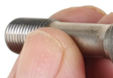
AFTERMARKET PERFORMANCE connecting rod bolts feature dimples at each end (dimple on the bolt head shown here).


Dorman’s aftermarket-exclusives and improved designs offer unique solutions for common OEM problems. Featured OE FIXTM products: Oil Filter Housing Assembly, Wheel Lug Bolts & Nuts, Engine Heater Hose Assembly, Valve Cover Kit, Axle Shaft, Shift Cable Bushing Kit, Keyless Entry Remote, Reman Transmission Control Module and more.
DORMAN INNOVATION AVAILABLE FIRST AT TM Scan to learn more or visit OreillyAuto.com/dorman-professional
be milled or the block/head may need to be replaced.
With the proper head gasket and head in place, prepare the head bolts as required (using the lubricant specified to threads and bolt head undersides). Tighten head bolts in multiple steps and in the proper sequence, following automaker service manual guidelines. Never fully tighten each bolt in one step. Aluminum heads require hardened washers under the bolt heads to prevent the bolt heads from digging into the aluminum. Be sure to apply the required lube to both sides of the washers.
Generically speaking, cylinder head fasteners will be tightened in a spiral pattern, starting at the center and gradually working outboard. Again, always follow the manufacturer’s tightening sequence, as certain cylinder heads may require a unique sequence.
Torque-to-Yield Head Bolts
Torque-to-yield (TTY) bolts are intended to obtain the required clamping load on initial tightening, without the need to retorque. They also address maintaining clamping load on bi-metal engines that feature an iron block and aluminum head, where thermal expansion rates differ. TTY bolt torque values allow tightening to within a fairly narrow stretch value, just short of the bolt’s yield point. These bolts are designed as one-time use bolts and should not be re-used. This is especially true if the bolts have been previously replaced and you are not sure if the previous

ONCE THE stretch gauge has been zeroed to a specific bolt, the bolt is installed and torqued to spec. The gauge is then placed back onto the bolt to see how much bolt stretch has occurred. In this case, this bolt has stretched just a tick over 0.004-inch. Max stretch for this particular bolt is 0.005-inch.
installer tightened them properly. While some automakers may state that a TTY bolt may be reused, don’t risk it if you are not certain of the bolt’s installation history.
Be aware that many TTY cylinder head bolts may require a torque-plus-angle spec (applying an initial torque value, followed by additional bolt head rotation by a specified number of degrees). Always follow the automaker or head gasket maker instructions.
Tightening by Torque-Plus-Angle
A great deal of applied torque is required to simply overcome bolt thread and underhead friction. Depending on how much applied torque is “wasted” due to this frictional factor, the final clamping load may or may not be as desired. In order to obtain more accurate clamping load, the OEMs developed torque-plus-angle tightening. This involves tightening the bolt to a specified initial level of torque application, followed by a critical number of degrees of additional bolt head rotation. As a result of design engineering, the automaker determined that a more accurate clamping load can be achieved by this multi-step process instead of relying on applied torque alone, ignoring the issue of frictional losses.
For example, the bolt tightening spec may dictate that the bolt is to be initially torqued to 35 ft-lbs., then tightened further by an additional bolt head rotation of 65 degrees. Some applications may call for an initial torque followed by several additional rotations (for example, 60 degrees followed by 80 degrees, etc.).
Once a torque wrench has been used to obtain initial torque value, there are several methods that can be used to achieve the required additional bolt head rotation.
You can apply a paint dot on the bolt head and a matching mark adjacent to the head. As you continue to tighten, you can monitor the degree of movement by observing the relationship of the dots. However, this is not an accurate approach. Another option is to use a separate
angle gauge. The gauge is connected to a wrench. The gauge is secured to the bolt head and the meter’s needle is zeroed. Continue to tighten, observing the movement of the indicator needle on the incremented gauge face.
Thanks to innovations in today’s digital torque wrench market, sophisticated digital torque wrenches are available that allow both torque and angle tightening with the same tool. This eliminates the need to keep swapping tools, and provides a greater degree of accuracy in achieving the final results.
Using an electronic digital torque/ angle wrench is simple and straightforward. Set the initial torque value and tighten the bolt to that value. Then press a button and switch to the angle mode. Continue to tighten until the desired angle is displayed on the viewing screen. (The tool will provide an audible/tactile alert.) This allows finishing the job with only one tool, with no need to disengage the wrench from the bolt.
Measuring Rod Bolt Stretch
If you are dealing with aftermarket connecting rods, these will feature aftermarket performance rod bolts. While OEM rod bolts may call for a torque or torque/ angle approach, performance aftermarket bolts will specify a torque value alone (no angle). In addition, the rod and/or bolt maker will provide bolt stretch information that indicates a maximum stretch
ALWAYS REFER to vehicle service manual instructions with regard to threaded fastener lubrication, as some bolts or nuts require a lubricant (engine oil or other specific lube), some require thread sealant, some require a thread locking compound and others require dry installation. The nature of thread prep will be specific to the application. If lubricant is required (for instance on cylinder head bolts or connecting rod bolts), lube must be applied to both threads and to the underside of the bolt heads. Aftermarket performance fasteners for cylinder head, main cap and rod bolt applications may recommend a specific brand/type of lubricant.


THREADED FASTENERS 22 JUNE 2024


REV UP YOUR SAVINGS! ALL-IN-1 SHOPPING ! Tools & Equipment | Shop Essentials © 2024 Wrenchers LLC. All Rights Reserved. 1-800-261-7729 Call Now for a FREE catalog! Ask about our price match guarantee. WE WILL NOT BE UNDERSOLD!
value. Instead of relying on a torque value alone, this allows the installer to monitor and verify how much the bolt is being stretched within its elastic range.
As an example, a specific rod bolt for a given application may call for a torque value of 70 ft-lb. The maximum allowable stretch for that bolt may be 0.005-inch. After applying the specified torque, the installer can use a bolt stretch gauge to check bolt length to make sure the bolt has not been stretched beyond its elastic point.
Using a bolt stretch gauge is rather simple but does require additional labor time. The bolt is first set up on the gauge and the gauge dial indicator is then set at zero. This provides a reference of the relaxed static bolt length. The bolt will typically feature a female dimple at each end that engages onto the anvils of the gauge. The bolt is then removed from the gauge, without disturbing the zero set. The bolt is then lubed and installed to the rod and torqued to recommended value. Next, the gauge is attached to the bolt again. The indicator needle will show how much the bolt has stretched. If not stretched, additional torque will be needed. If the stretch did not exceed maximum, that rod bolt installation is done.
This procedure must be repeated with each individual bolt, starting with adjusting the stretch gauge indicator to

zero with the bolt relaxed. Do not assume that all bolts, even though new, are exactly the same free length. Due to manufacturing tolerances, each bolt may deviate a few thousandths of an inch.
Wheel Fastener Torque
While the use of pneumatic or cordless impact wrenches is common practice for wheel service, the proper approach is to use a torque wrench. Yes, this takes more time, and many shops are unwilling to follow this recommendation, but using a torque wrench is the only way to properly install wheels to avoid potential under- or over-tightening. Especially when dealing with alloy wheels, achieving the specified wheel fastener clamping load is even more important. In addition to the clamping force concern, it is imperative that all fasteners are tightened evenly — that is, to the same value. Uneven tightening can easily result in brake rotor distortion. While the use of an impact wrench may be suitable for wheel fastener removal, care must be taken when dealing with alloy wheels. Make sure that the socket wrench properly fits and does not contact wheel fastener well/recess to avoid scuffing or galling the alloy material. Also, make sure to use the proper style of socket wrench. (Don’t use a 12-point socket for a 6-point nut to avoid marring and burring the fastener hex).
At the very least, if you insist on using an impact wrench to tighten, use a torque stick. These are available in all common hex sizes and are stamped and color-coded for torque value. When the designed torque is achieved, the torque stick beam will twist slightly (much like a torsion bar), to prevent over-tightening. This is not as accurate as a torque wrench, but the results will usually be close enough to be acceptable.
compress the wheel fastener well/pocket. Over-tightening and/or uneven tightening can easily result in brake rotor distortion, which in turn can lead to brake pedal bounce and pulsation.
Before wheel installation, verify that both male and female threads are clean and in good condition. Don’t assume that all threads are viable. If in doubt, replace them. Bear in mind that most wheel fastener torque values are based on the use of dry threads. However, assumptions can lead to problems. If in doubt check the service manual. Also be aware that some “exotic” performance vehicles may feature alloy wheel nuts, which may require lubrication to prevent thread galling. Again, if in doubt, check the service manual.
In order to tighten the fasteners to full torque value, either have a helper hold the brakes while you tighten, or initially snug the fasteners to fully mate the wheel to the hub, then lower the vehicle until the tires just kiss the floor — to prevent the wheels from turning while you tighten — and apply full torque.
Always tighten the fasteners in a crisscross pattern in order to evenly distribute the clamping load. This reduces the chance of distorting the brake rotors.

any wheel fastener recess to avoid marring wheel finish. Always, without exception, tighten fasteners in a criss-cross pattern to evenly distribute the load.
When installing wheels, whether steel or alloy, always employ a torque wrench to properly achieve the recommended torque value. Over-tightening and/ or uneven tightening can potentially
MIKE MAVRIGIAN has written thousands of automotive technical magazine articles involving a variety of specialties, from engine building to wheel alignment, and has authored more than a dozen books that crisscross the automotive spectrum. Mike operates Birchwood Automotive, an Ohio shop that builds custom engines and performs vintage vehicle restorations. The shop also features a professional photo studio to document projects and to create images for articles and books.

THREADED FASTENERS 24 JUNE 2024
THE CLAMPING load on wheels to hubs is critical. While using an impact wrench to tighten wheel fasteners may save time, it’s far more important to achieve proper torque value in order to secure the wheels, avoid brake rotor distortion and to avoid future service issues dealing with over-tightened fasteners that may be difficult to remove. When dealing with alloy wheels, make sure that the socket wrench safely clears


Toyota Dynamic Force Engines
New designs innovate and offer increased efficiency and lower emissions.

 BY JEFF TAYLOR


26 JUNE 2024 TOYOTA ENGINES


THE FORMATION OF the Toyota New Global Architecture (TNGA) is aimed to streamline production and development across all of Toyota’s automotive manufacturing. The results of TNGA have led to a dramatic reduction in engine platforms from over 800 variations to fewer than 20. Alongside TNGA, Toyota introduced the Dynamic Force Engine family, featuring I3, I4, and V6 engines with turbo and non-turbocharged applications.
Toyota’s Dynamic Force Engine prioritizes thermal management to enhance efficiency and reduce emissions. Techniques include high-speed combustion technology, a variable cooling system, continuous variable capacity engine oil pump, and an electrically controlled variable intake camshaft phaser. These innovations aim to maximize energy extraction from gasoline fuel injected into the engine.
The Dynamic Force Engines also introduced a notable change in Toyota’s engine naming nomenclature, integrating engine displacement between a two-letter code. For example, the A25A signifies a 2.5liter engine.
This article focuses on the A25AFKS engine, with its remarkable thermal efficiency of up to 40%. Its hybrid counterpart, the A25A-FXS, achieves an outstanding 41% efficiency, surpassing traditional internal combustion engines typically running at around 35%. But please note that almost all of these technologies are used across the entire Dynamic Force Engine family.
A25A Dynamic Force Technology: Revised Intake Design. The Dynamic Force Engine has several notable intake port and cylinder head design modifications from its predecessor 2.5L four-cylinder engine design. These were needed to produce a strong, tumbling air flow into the cylinders enhancing high-speed
YOU CAN see the high-pressure fuel pump on the valve cover that feeds the GDI injectors, and you can also see the Port Fuel Injectors supply line coming off the high-pressure pump and heading to the Port Fuel Injectors under the plenum.
VEHICLESERVICEPROS.COM 27 MOTOR AGE
combustion, boosting engine power output and fuel efficiency while reducing exhaust pollutants.
The strong tumbling air motion used to accelerate the combustion process has been achieved by widening the angle between the intake and exhaust valves, from approximately 23 degrees to approximately 40 degrees. This allows for a straighter intake air flow. Wider valve angles are used to enhance the air tumble motion and lower the air flow resistance for more effective combustion. But a wider valve angle isn’t the only change to the intake port design. The intake valve seat is now laser clad. By using a process known as “laser cladding,” a laser beam is used to melt a copper-based alloy powder into the aluminum cylinder head. This creates intake valve seats that are directly integrated to the cylinder head. These laser clad intake valve seats are considerably thinner than the traditional press-fit intake valve seats, and they improve intake valve cooling, increase wear resistance, and permit the intake port to have a more ideal size and shape. Traditional press-fit valve seats are still used for the exhaust valves.
A25A Dynamic Force Technology: PCV Integrated Into Cylinder Head. The PCV valve is mounted in the cylinder head, between the intake manifold (the intake manifold incorporates the crankcase ventilation circuit) and cylinder head to regulate temperature and lower the possibility of valve freeze-up. An external oil separator is mounted on the block under the intake manifold.
A25A Dynamic Force Technology: D-4S Fuel Delivery System. Toyota uses the D-4S fuel system to supply fuel to the A25A Engine. This system combines both a Port and GDI fuel injection system. To provide the best fuel mixture in the cylinder under the most operational situations, both sets of injectors collaborate. The engine’s particulate matter emissions were significantly reduced by using both port and direct fuel injection

and exhaust emission reductions were a major factor in the engine’s development. The purpose of the port fuel injectors is to supply fuel to the engine within a designated operating window; they are not intended to clean the intake valves. The long 10-point spray low-pressure port fuel injectors have a modified plug that differs from the conventional Bosch standard injector plug of the past. The sixhole GDI fuel injectors have been updated for improved fuel aiming (angled toward and across the piston) and placement in the cylinders, but they work exactly like any other direct fuel injection system. By using this revised spray pattern, valve interference has been reduced, enabling high-pressure atomized spray to better enter the combustion chamber independently of airflow. This injector design makes the fuel more evenly distributed, which helps it mix better with the air coming in, which leads to better burning no matter what the driving conditions are like.
To achieve stricter emission control levels, the Powertrain Control Module (PCM) now only partially lifts or partially opens each GDI injector during an injection pulse, when the engine is cold
or warming up. Full injection GDI lift resumes at normal engine temperature. This method significantly reduces combustion chamber particulate matter by 60% over the prior engine design.
The PCM times the port and GDI injections during a cold start to reduce emissions and stratify combustion. To accomplish a stratified combustion process, the PCM regulates the timing of the port and direct fuel injectors during a cold start. Right after a cold engine start, fuel is injected into the intake port during the exhaust stroke, and after the compression stroke, the GDI injector injects fuel, creating a stratified air-fuel mixture. The area around the spark plug will be richer than the rest of the combustion chamber. This late injection procedure allows for retarded ignition timing, which raises exhaust gas temperature and accelerates catalyst warmup.
The PCM will cycle both the port and the GDI injectors occasionally while at idle and there will be an audible change in the engine’s sound as this happens. This is most notable if the technician has the engine decorative/ noise deadening cover off the top of the engine in the shop. This is a normal operation, used to flush the


28 JUNE 2024 TOYOTA ENGINES
THIS IS the electric water pump, mounted to the block just above the AC compressor. The mapped thermostat is mounted to the back of the water pump (out of view).
STANDARDS OF EXCELLENCE RAISING THE


Our 10AP Series offers the convenience of wide or narrow installation wrapped up into one configurable package. This durable, safe, and reliable car lift features an expandable top beam and BI-METRIC™ arms to suit virtually every vehicle lifting requirement – symmetric or asymmetric. The 2-in-1 design gives operators the option of loading vehicles either symmetrically (centerline of vehicle at column) or asymmetrically (centerline of vehicle behind column). The simple, yet highly sophisticated is sure to keep operating costs low and productivity high. Check out the full line of 10AP lift series at bendpak.com or call us at 1-800-253-2363


Certified to meet the standards of ANSI/ALI ALCTV: 2017
. Bi-Metric Swing Arms Innovative Safety Lock Triple-Telescoping Arms LEARN MORE 1-800-253-2363 • BENDPAK.COM ©2024 BendPak Inc. All rights reserved. 10AP SERIES | Two-Post Lift Adaptable Design Symmetric or Asymmetric • Provides the Ultimate In Safety & Vehicle Fall Protection AUTOMATIC SWING ARM RESTRAINT SYSTEM ASARS
hot fuel from the GDI injectors and high pressure GDI pump.
A25A Dynamic Force Technology: Variable Flow Cooling System. Conventional mechanical coolant pumps, which are powered directly by the engine, consistently circulate coolant when the engine is in operation, even when cooling is not needed. By implementing a variable flow cooling system, Toyota has been able to reduce friction, enhance engine warm-up capability, and lower fuel consumption.
The system uses an electric coolant pump and other coolant flow controls controlled by the PCM. This cooling system design ensures ideal coolant flow and volume. It will support a specific engine temperature, regulate heater core output, and flow to the Automatic Transmission Fluid (ATF) heat exchanger. And it can do this under the entire range of operating conditions, even when the engine


is off. (The Dynamic Force Engine has a hybrid version, and the non-hybrid does have Toyota’s “Smart Stop Technology,” so these engines can be stopped frequently.)
During the first phase of a cold start, the electric coolant pump may not pump any coolant, as the PCM will decide what coolant flow is needed. This enables the engine and the catalytic converter to reach the ideal temperatures more rapidly. For improved heat transfer, the coolant and engine oil internal passages are cast closely together. This design provides quicker engine warmup and improves engine cooling in high-load scenarios.
The thermostat that regulates the operating temperature of the cooling system has also been upgraded within the Dynamic Force Engine architecture. The A25A and other engines in the Dynamic Force family are using a mapped thermostat enabling the PCM to regulate
the operating temperature. The PCM will provide a duty cycle control to the thermostat assembly. This can accelerate the opening process by heating the wax, which in turn causes expansion. This allows for improved flow when the engine load demands it. This control enables the thermostat to regulate the circulation of the coolant in the engine cooling system with more precision. The mapped thermostat in the A25A opens at a temperature of 176 degrees to 183 degrees which is approximately 10 degrees cooler than the typical previous four-cylinder engine. It should also be pointed out that this cooling system is a low pressure system, with an expansion tank cap pressure of 12.75 psi (88kPa).
The variable flow cooling system also has two Flow Shutting Valves (FSV) that scan tools may call Coolant Water Routing or Coolant Switching Valves. These
30 JUNE 2024 TOYOTA ENGINES We Train Technicians in Hybrid and EV Service and Repair www.FIXHYBRID.com OFFICE: 508-826-4546 EMAIL: CRAIG@FIXHYBRID.COM HOURS: 9-5 EST MON - THURS TRAINING CENTER LOCATED IN WORCESTER, MASSACHUSETTS • HV Safety Certification • 450 Page Technical Book written in House • Service Advisor Training • Hybrid EV Tools and Equipment • ASE Preperation Class For L3 • Live and Recorded Online Training • Hands-On-Classes • Consulting 2406MA_VanBatenburgsGarage.indd 1 4/4/24 1:08 PM
coolant control valves control the coolant flow through the heater core (FSV1) and the ATF warmer/cooler (FSV2). The FSV valves have a unique magnetically controlled operation to control coolant flow. When the PCM applies power to them they will become magnetized and close.
The variable cooling system of the A25A engine allows for four distinct cooling system modes of operation.
• Early Warm Up: To warm up to operational temperature faster, the Early Warm Up mode stops coolant flow to the heater core and ATF warmer. Coolant will still flow through the block, cylinder head and EGR cooler. To minimize piston slap during warmup, the flow rate is reduced.
• Heater Priority: To improve heater efficiency, the heater priority mode lets coolant pass to the heater core while preventing flow to the ATF warmer.


PROFESSIONAL GRADE FILTRATION
Since 1923, we’ve been making filters that meet the quality of workmanship from professionals like you. And, they’ve only gotten better.


PurolatorTECH™ Oil Filters
• Designed for Optimum Oil Flow
• Rugged Internal Construction
• 96.5% Dirt Removal Power™

PurolatorTECH Air Filters
• Enhanced Engine Airflow
• Multi-Fiber, High-Density Media
• Trap More Debris Than Economy Filters

PurolatorTECH Cabin Air Filters
• Optimize HVAC and Defroster Performance
• Available in Particulate or Carbon
• Meet or Exceed Manufacturer Requirements
VEHICLESERVICEPROS.COM 31 MOTOR AGE
PurolatorNOW.com
2406MA_PurolatorFilters.indd 1 5/14/24 10:25 AM
THIS PHOTO shows the heater core Flow Shutting Valve (FSV1). It is a magnetically controlled valve that will regulate when coolant can flow through the heater core.
• Output Enhancement: This is applied when there is a high engine speed and load. The mapped thermostat will open faster and both FSVs will be opened for optimal coolant flow and heat transfer for high-performance cooling and engine knock prevention. The PCM-controlled electric water pump speed will be adjusted for best heat transfer and coolant flow.
• Max Cooling: In this mode, the heater core FSV is closed, like the old cable or motor-operated heater control valve, to enhance air conditioning evaporator efficiency.
The variable electric water pump, the mapped thermostat and both FSV valves are being continuously monitored by the PCM for issues, and that means they are going to be able to set DTCs. Electric water pump DTCs can be set for opens, shorts, no signal, actuator stuck and pump overspeed.
It should also be noted that some cooling system failures (water pump and FSV issues) may cause the vehicle to go into a limp-in or failsafe mode and will limit the engine’s rpm to protect itself.
If the cooling system is serviced or drained, there is a special coolant fill procedure that must be followed to ensure that the system is properly bled. This procedure is not activated with a scan tool, but a scan tool is needed to show the tech that the Engine Coolant Mode has been entered by observing the water pump speed (water pump speed will be increased to approximately 5,250 rpm and both FSV valves will be opened).
The engine cooling fill procedure:
• Disconnect the quick connect water hose on the EGR valve assembly.
• Slowly fill the radiator until coolant appears at the EGR valve.
• Reinstall the quick connect water hose on the EGR valve.
• Ensure the coolant level is correct in the rad and expansion tank and install the coolant caps.
• Perform the Engine Coolant Filling

Mode procedure to complete the bleeding procedure.
Enter the Engine Coolant Filling Mode as follows.
• Place the shifter in park.
• Start the engine and run the engine at 1,500 rpm for 15 seconds or more.
• Check the speed of the electric water pump on the scanner. It should increase in speed when the engine speed is raised to 3,000 rpm for 10 seconds and then let the engine idle.
• Repeat the procedure three times.
• Once the Engine Coolant Filling Mode is entered you will see a sudden shift in the water pump speed.
• NOTE: The vehicle will typically enter Engine Coolant Filling Mode the first time the engine is revved to 3,000 rpm. You must watch the water pump speed on the scan tool data.
• Turning off the engine will exit the Engine Coolant Filling Mode.
• After exiting, verify the coolant is at the correct level.
A25A Dynamic Force Technology: Cooling Fan Control. A single motor, variable speed assembly cooling fan
with a communications line to the PCM is used to manage the cooling fan operation, replacing the earlier twin cooling fan assembly. A high-powered brushless fan motor is used, enhancing cooling performance, while reducing the assembly’s weight. The motor is equipped with an integrated PWM controller that allows for precise control of the motor’s rotational speed while maintaining a small and lightweight design. The cooling fan blades have a unique shape, which allows for quiet, even airflow. An active shutter system is also a part of the cooling system.
A25A Dynamic Force Technology: Variable Displacement Oil Pump: An electronically controlled variable displacement oil pump is used on the A25A engine. By adjusting engine oil pressure and volume in response to engine oil temperature, rpm and engine load, this oil pump minimizes friction, while maximizing lubrication.
The PCM regulates the system using an oil control switching valve, and the oil pump is a Trochoid Design. The PCM can smoothly adjust engine oil pressure between minimum and maximum using this
32 JUNE 2024 TOYOTA ENGINES
THE DYNAMIC Force Engine family uses a low-pressure cooling system, 88kPa is only 12.5 PSI, lower than most cooling systems.
oil pumping system to meet the engine’s requirements. When a low oil output volume is needed, the oil control switching valve is activated by the PCM. This raises the pressure inside the control chamber of the oil pump, reducing the size of the pumping chamber by forcing the outer-driven gear closer to the inner drive gear. This will reduce the volume of oil the pump can pressurize, lowering the engine oil pressure. To increase the engine oil pressure the PCM will lower the pressure inside the control chamber of the oil pump. An integral spring will force open the control chamber, increasing the size of the pumping chamber, increasing the oil pump’s volume, raising the engine oil pressure. This is also the default position of the control chamber if the oil control switching valve fails, or the wiring to it becomes damaged.
The A25A uses piston cooling oil jets to reduce friction and maintain piston temperature to reduce engine knock. By controlling the engine oil pressure with the variable displacement engine oil pump, these piston cooling oil jets will only be activated when the oil pressure is increased, and piston cooling is needed. When the engine is cold, and the oil pressure is lower, the piston cooling jets aren’t functional, allowing for better piston warmup and reducing piston noise.
Use of the proper engine oil viscosity is required. Incorrect engine oil viscosity can set fault codes for low pressure in three stages: minor, moderate, and severe. The PCM can even limit the engine’s rpm, acting as a failsafe to protect itself if the oil pressure is too low.
A25A Dynamic Force Technology: Cooled EGR Assembly. Before the EGR gas passes through the EGR valve, it is directed through the cylinder head and into an EGR cooler to cool it. The cylinder head has molded fins in the EGR passage to maximize surface area, which helps with heat transfer in two ways: heating the cylinder head to quickly warm a cold engine and cooling the EGR gases. When

the engine is cold, the EGR valve will be activated, routing EGR gases through the cylinder head to warm the engine faster.
A25A Dynamic Force Technology: Variable Timing VVT-iE. A DC brushless electric motor is used by the VVT-iE to regulate the phasing of the intake camshaft. This allows for precise intake camshaft phase control at low engine speeds or low engine temperature because it is powered by an electric motor, not engine oil.
Depending on the engine operating conditions, the PCM can accurately adjust the VVT-iE electric motor’s rotational speed and direction to adjust the intake camshaft phase to the desired position. This enables a broad control range over the power spectrum and enables Atkinson cycle engine operation.
Toyota’s Dynamic Force Engine’s use of multiple variable systems and careful engineering dramatically improves this engine’s thermal efficiency.

SCAN TO READ MORE OF JEFF TAYLOR’S ARTICLES, AND TO SEE ADDITIONAL DIAGRAMS FOR THIS STORY.
Using high-speed combustion, an enhanced intake design, a variable flow cooling system, a variable engine oil pump, variable intake camshaft phasing, D-4S fuel delivery, PCV integration, and a cooled EGR assembly collectively enhance engine efficiency while reducing emissions. Toyota continues to innovate in automotive engineering, and their commitment to combustion optimization and environmental sustainability shows their dedication to producing reliable, high-performance engines.


JEFF TAYLOR is a seasoned professional at CARS Inc. in Oshawa with 40 years in the automotive industry. As a skilled technical writer and training developer, he holds licenses in both automotive and heavy-duty vehicle repair. Jeff excels in TAC support, technical training, troubleshooting, and shaping the future of automotive expertise.
VEHICLESERVICEPROS.COM 33 MOTOR AGE
THE DYNAMIC Force variable cooling fan is PWM controlled, a single blade, and has a special design for quiet and efficient air flow.
Stumped by the Pump
The heart of the high-pressure GDI fuel system is the HP fuel pump. But it relies on the camshaft to function.
BY BRANDON STECKLER // Technical Editor
THE DATA DOESN’T LIE


WELCOME BACK TO ANOTHER EDITION OF “THE DATA DOESNT LIE,” A REGULAR FEATURE, WHERE I POSE A PUZZLING CASE STUDY.

THIS ONE COMES from my close friend Brin Kline, owner of Assured Auto Works in Melbourne, Fla.
He was faced with a 2006 Mazda 6 2.3L turbo exhibiting poor power output under cruise and acceleration. The vehicle seemed to idle just fine but barely performed, even under low load driving conditions.
Preliminary Analysis
Using his Snap-on Verus Edge scan tool, Brin began his analysis with an all-module DTC scan followed by a careful analysis of pertinent PIDs.
DTC P0012 (“Intake cam position timing over retarded”) was present and may offer some insight into the cause of the low-power driveability concern (Figure 1). The P0012 has been present for multiple shop visits but never accompanied by any driveability concern. This approach to driveability faults allowed him to gain insight into the nature of the fault right from the driver’s seat.
One particular PID stood right out (Figure 2). The fuel rail pressure being exhibited by the sensor in the rail is nowhere near the 725-psi commanded during a steady state idle condition.

In fact, the pressure in the fuel rail closely mimics that of the low-pressure fuel system feeding the high-pressure fuel pump (HPFP).
This begs the question “why?”
The HPFP is a device driven by the camshaft. The specialized cam lobe in this configuration fully strokes the pump’s piston three times per engine cycle. Part of the HPFP is the fuel volume regulator valve (FVR). This device serves as the “trap door.”
With the FVR energized and trapping fuel in the pump chamber, the stroking of the piston by the HPFP cam lobes will produce pressure.
The earlier in the stroke the trap door is shut, the more pressure is produced from a pump stroke. The later the trap door is shut, the less pressure is produced from a pump stroke.
Some items to consider that affect pump output:
• The low-pressure fuel system (in-tank) must supply the HPFP with fuel.
• The camshaft must stroke the pump properly.
• The FVR must function to trap fuel.
• Camshaft timing will drastically affect HPFP output.
Observations From the Road Test
Upon conducting an analytical road test, the vehicle seems to idle just fine. Under acceleration, although normal power output cannot be attained, it seems to perform relatively smoothly. More data
34 JUNE 2024 TECH CORNER
FIGURE 1: THE INTAKE camshaft provides the mechanical drive for the HPFP. This configuration is tri-lobal, but other configurations exist.
IMAGE BY BRANDON STECKLER AUTOBLOG HPFP Cam Lobes High-Pressure Fuel Pump CMP Sensor Reluctor Fuel Volume Regulator Valve


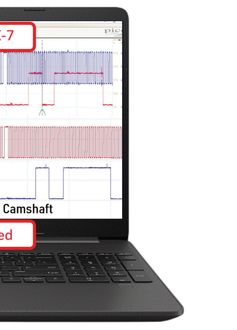
3: A COMPARISON of the CKP/CMP correlation waveforms (between a known-good example and our suspect vehicle) was carried out and proves a shift in camshaft timing occurred.
needs to be gathered but the current state of operation says a lot about the engine’s mechanical condition, considering all the data evident at this time.
Scoping the CKP/CMP for correlation, and comparing it to a known-good example, yields a shift in intake cam timing/ retarded (Figure 3). However, retarded intake cam timing would delay the piston stroke and increase pressure output.
Solving why the fuel rail pressure matches the low-pressure system is what the primary goal now is and of course, the bullet points listed earlier are what is to be considered.
To eliminate a potential circuit issue with the fuel volume regulator valve (the “trap door”), a voltage command/current waveform was obtained and indicated no issue with the performance of the valve or the related circuitry (Figure 4).
This leaves only a mechanical fault on the table.
The Data Doesn’t Lie
With all the information in front of us, and the desired information not yet obtained, we are faced with deciding how to proceed. Here are some bullet points of what we know to be factual, and I will ask all of you, diligent readers, for your input:
• Although underpowered, the engine idles and performs smoothly.

FIGURE 4: BEFORE CONDEMNING any high-pressure fuel system components, a test of the circuitry related to the fuel volume regulator valve (and the performance of the valve itself) was conducted using a multi-trace digital storage oscilloscope.
• The fuel rail pressure matches the low-pressure system output.
• The low-pressure system produces a sufficient 47 psi of fuel pressure.
• A DTC P0012 is stored.
Given this information, what would you do next?
1. Reset camshaft timing and re-evaluate
2. Inspect camshaft/pump condition
3. Condemn FVR (HPFP assembly)
4. Condemn HPFP piston/chamber (HPFP assembly)
VEHICLESERVICEPROS.COM 35 MOTOR AGE
FIGURE 2: THE FUEL rail pressure didn’t exhibit the commanded 725 psi as expected but instead exhibited pressure that mimicked what is seen on the pressure gauge connected to the low-pressure supply system. This is a valuable clue.
PHOTO BY BRIN KLINE ASSURED AUTO WORKS PHOTO BY BRIN KLINE ASSURED AUTO WORKS PHOTO BY BRIN KLINE ASSURED AUTO WORKS
FIGURE

Solved: 2015 Toyota Land Cruiser, Loss of Power
From April 2024, Motor Age
BY BRANDON STECKLER // Technical Editor
What would you recommend doing next, given the data bullet points in last month’s challenge?
Given this information, what would you do next?
1. Replace PCM for erratic internally shorted 5V reference
2. Monitor 5V reference circuit at PCM, with amp probe
3. Rewire all the 5V reference circuit feeds on the vehicle
4. Replace CKP/CMP sensors for intermittent 5V ref short to ground
For those of you who chose answer No. 2, congratulations. An amp probe placed around the 5V reference wire of the PCM would’ve shown an increase in current each time the sensor signals failed.
Careful inspection prior to more pinpointed testing of the wire harness would’ve revealed a poorly secured har-
ness. The connector pigtail for the fuel tank pressure sensor allowed the 5V reference wire to melt on the exhaust pipe and short the signal to ground, pulling it low and causing the stall (Figure 5). Although a faulty PCM could cause this issue, it wouldn’t be wise to condemn a computer without eliminating external faults. Rewiring all existing 5V reference circuits would have solved the issue but would be a tremendous investment in
36 JUNE 2024 TECH CORNER
PHOTO 264393497 © HARAZAKI ANANTA HONDRO DREAMSTIME.COM

FIGURE 5: THIS DAMAGE to the fuel tank pressure sensor 5V reference wire occurred because the wire melted as it encountered the exhaust system. As the 5V reference wire found a path to ground, it pulled the signal low and created the elusive driveability symptom.
time and not an efficient use of that time. Replacing the CMP/CKP sensors is not going to solve this issue but could be the cause of the stalling symptom. Without evidence to support the sensor failure, it would simply be a guess and not very professional to conduct analyses like that.
Be sure to read the next Motor Age issue for the answer to this month’s challenge and what was discovered!

SCAN TO READ MORE ARTICLES LIKE THIS
BRANDON STECKLER TACKLES A NEW VEHICLE EACH MONTH. FOLLOW ALONG HERE IN MOTOR AGE, AND ON VEHICLESERVICEPROS.COM!
BRANDON STECKLER is the technical editor of Motor Age magazine. He holds multiple ASE certifications. He is an active instructor and provides telephone and live technical support, as well as private training, for technicians all across the world.
BRAKE DRUM AND ROTOR PULLER
Saves time and reduces damage to the wheel bearing by eliminating the need to repeatedly strike or heat the brake drum to free it from the hub
The Brake Drum & Rotor Puller is adjustable with a 17" spread and 6" reach to accommodate the most common drum sizes
Includes specially designed jaws to maximize surface contact ensuring uniform grip even on deteriorated drums


VEHICLESERVICEPROS.COM 37 MOTOR AGE
WWW.LANGTOOLS.COM MADE IN U.S.A.
#833
MAXIMIZES SURFACE CONTACT ENSURING UNIFORM GRIP 2406MA_A&EHandTools.indd 1 5/8/24 1:53 PM

Transmissions
BY CRAIG VAN BATENBURG


38 JUNE 2024 ELECTRIC VEHICLES
changed with HEV,
EV?
What’s
PHEV and
and Gearboxes


39 MOTOR AGE VEHICLESERVICEPROS.COM
IF YOU HAVE worked on transmissions for combustion engine vehicles, many transmissions on HEV and PHEV will be familiar. Some need more explaining. Most techs know about the Toyota power split device or eCVT, but did you know that Ford uses the same principle? What about the Chevy Volt? Let us take a closer look. Those transmissions require more study so we will do what we can in this article. Other makes, like Honda, have more unique designs. At ACDC we call all high voltage vehicles “EMVs.” There are great videos that animate the workings of an EMV transmission, so use them to supplement this article. The added instant torque of high voltage motors has stressed many conventional transmissions, like the VW Jetta HEV. There is a lot to learn, so let’s get started.
The conventional transmission was originally designed for a vehicle with an internal combustion engine (ICE). As the vehicle gained road speed, the RPMs of the crankshaft could be slowed down by shifting to a higher gear ratio and then the “torque” would be in a rpm range that had the ability to keep accelerating the vehicle. Once a powerful electric motor was added to the driveline, the need for more torque was reduced. As long as an ICE was used, a transmission was needed. The road speed needs to match the torque of the ICE. When the ICE was eliminated, the changing of gears became optional. Most EV applications are single speed gear boxes. The most common set up is a 10 to 1 gear ratio. No shifting with direct drive. Some transmissions have a high voltage motor(s) located inside (Figure 1) while other designs locate the motor in between the transmission and ICE. As long as the wheels turn the right direction when they need to, anything is open for development.
Standard Shift Transmission
Honda was the only OEM to incorporate this type of transmission into a light duty hybrid car. The Honda Insight (Figure


2) came out in M/Y 2000 and a 5-speed manual transmission was all they offered. To make this happen, two switches were installed in the transmission, one for first gear and one for neutral. A clutch switch was also attached, so when the car was slowing down to 18 mph, the ICE would shut off and the car would coast to a stop. The driver had to be trained to keep the
transmission in neutral or the ICE would continue to run. If the clutch was out and the car was in “N,” the ICE would stay off for a long time. When the driver put the clutch to the floor and shifted into first gear, the ICE would start instantly and silently if it was in “READY to DRIVE” mode. Later on the Honda CR-Z HEV could be ordered with six-speed stick.

ELECTRIC VEHICLES 40 JUNE 2024
FIGURE 2: THE FIVE HEVs for sale in 2005. Honda Insight shown at center.
ACDC ACDC
FIGURE 1: A THREE-PHASE motor inside a 2019 Honda Accord HEV transmission.


CVT and eCVT
What is the difference between a “CVT” and an “eCVT”? A CVT (Figure 3) is a Constantly Variable Transmission. The difference mechanically speaking is an eCVT uses two electric motors, the ICE and a planetary gear set to maintain ideal engine rpm and wheel speed. A CVT uses a metal belt and two hydraulically actuated pulleys to maintain optimal engine rpm to wheel speed. The CVT and eCVT allow the ICE to run at an rpm suitable to power the car’s wheels independently of the vehicle’s speed. Because of this, the ICE doesn’t have to increase in speed as the car goes faster, so the car feels very different than a “geared” automatic or standard shift vehicle. The torque multiplication effect of a CVT is absent in an eCVT and is replaced by the torque of the electric motor assisting the ICE.
If you do not already know about the eCVT, here is a brief overview on the eCVT used in most Ford and Toyota HEVs and PHEVs. The engine’s crankshaft is connected to the planet carrier (Figure 4). Motor/Generator 1 (M/G1) is connected to the sun gear and M/G2 is connected to the ring gear. The rotation of the ring gear drives the car via reduction gears or a chain and then to the differential. If you already know that, make sure you keep the terms CVT and eCVT straight as you study more on your own. This can seem like a complex subject, so make sure you study and learn from someone with the knowledge needed to help you learn more. You need to get clear about the Toyota/Ford eCVT to understand the power flowing to the wheels.
Toyota / Ford Modes of Operation
Here are the modes that most Toyota hybrids use (generation 1998 to 2024) and most Fords use (2005 to 2024). On the 2016 Prius liftback (Gen 4), mode 10 was added. If you know these modes then your skill level is high and troubleshooting will be easier for you. We do not have space

here to explain each mode, so get more training if you need it.
1. Starting the ICE with M/G1. Must be in park.
2. Backing up. Where is reverse gear?
3. Slow speed electric drive on HV battery only.
4. Reverse with ICE on. Why?
5. Starting the ICE while driving in EV mode.
6. Driving with the ICE, the CVT function.
7. Full Power operation.

8. Regenerative Braking in “D”.
9. Braking in “B” mode. (Ford uses the letter “L”)
10. Full Power — 2016-2024 Prius has a twist.
Another Dutchman, Niels Blaauw, put a video together and in under 15 minutes you will get an animated view of the inner workings of a Power Split Device (PSD) in a hybrid. (Watch the video using the QR code.)


AWD Systems
In order for a FWD hybrid to be an AWD vehicle, Toyota designed and built a rear drive differential (Figure 5) that was powered by a three-phase motor. Toyota called it Motor/Generator Rear (M/GR). Ford chose to add a “Power Take Off” (PTO) to their eCVT and add a conventional drive shaft and typical rear differential drive
ELECTRIC VEHICLES 42 JUNE 2024
FIGURE 5: CUTAWAY OF the electric rear drive unit. Toyota design.
FIGURE 3: A CVT transmission with integrated three-phase motor.
Toyota/Ford eCVT arrangement
ACDC ACDC
ACDC


in their Ford Escape (M/Y 2005-2012). The Ford Escape hybrid came in FWD or AWD. The PTO was bolted to the eCVT so the same eCVT was used in all drive types. Understanding the Ford AWD system is conventional training so we will not cover that here.
Toyota MGR
When the Lexus RX 400h and the Toyota Highlander HEV came to America in M/Y 2006, they had AWD. It was an option on the Toyota. No drive shaft — just three orange cables heading from the inverter to the rear axle. This system is very common today.
The Volt Transmission
The M/Y 2011-2015 drive unit is a 4ET50 (Figure 6). There are two electric motors, one traction motor/generator, M/G2 (GM calls it motor B) rated at 111kW and the other motor generator, M/G1 (or motor A in GM terms), rated at 58kW, a 1.4 liter gasoline engine, one planetary gearset to blend power inputs, and three clutches to control power inputs.
The Drive Modes
Mode 1: When the battery pack is charged, M/G2 is the sole source of propulsion at low speeds and hard acceleration from a stop. To do this, the planetary ring gear is locked to the case with clutch 1 (C1) and M/G2 is rotating the sun gear. The planet gears are spinning and forcing the carrier to move (Figure 7). The carrier is geared to the final drive and the wheels are moved in either a forward or rearward direction. Mode 2: This is now a two motor EV. As speed increases (about 40 mph), the ring gear is unlocked by opening C1 and coupled to M/G1 with C2, allowing both motors to work in tandem for improved efficiency and adding more range of pure EV operation at highway speeds. Watching the PIDs for M/G2 and M/G1 while someone else drives will help you see the inner workings of a great design. Both motors will be spinning in the same direction but

at lower speeds than in Mode 1. This is why the range is slightly better than a single motor drive system.
Mode 3: When the battery pack reaches its minimum charge of about 20% in normal operation, or 40% in Mountain Mode, the Volt goes back to Mode 1. Based on load and SOC, the ICE will start when C3 is closed and M/G1 cranks the ICE. Under hard
acceleration, electricity generated by the 1.4L ICE, plus reserves in the battery pack, provide Mode 1 operation. Additional electricity from M/G1, being rotated by the ICE, helps maintain a minimum charge in the battery pack (about 20% SOC). Once you are at a charging station, plug into a charger (really an EVSE) and recharge the HV pack. The reasoning here is not

ELECTRIC VEHICLES 44 JUNE 2024
ACDC
FIGURE 6: CHEVY VOLT cutaway transmission on display at SAE congress in Detroit.
ACDC
FIGURE 7: DIAGRAM OF the Chevy Volt connections to the planetary gear set.
to fully charge the HV battery as the fuel economy would be very low. The Volt will shift out of Mode 3 if the car will be more fuel efficient. That happens at about 40 mph. In Mode 3, the ICE is only a generator. Mode 4: The Volt is now a hybrid with two motors. The operation is similar to Mode 3, but now the ICE is started by M/ G1 with C3 closed, connected to the ring gear via C2. By connecting the clutches, some torque from the gasoline engine is transferred through M/G1 (a generator now) to the ring gear and from there to the wheels. M/G1, via the battery pack and inverters, provides some electricity to M/ G2. M/G2 and the ICE are the sources of propulsion. M/G2 must have power or the eCVT will be in neutral. Blending torque from M/G2 (the traction motor) and the ICE increases efficiency at highway speeds by 10 to 15%, rather than the use of the M/ G2 alone. Mode 4 uses the same principle as the Toyota Prius eCVT. Less fuel is being used at higher road speeds than in Mode 3.
AWD Tesla System
All Tesla cars were RWD for years. The inverter, drive system and three-phase motor (Figure 8) were housed in one unit. The transmission was not used for shifting, but it did multiply torque. The single gear ratio was chosen by knowing the torque, the maximum rpm of the motor and the top road speed required. Tesla announced the introduction of AllWheel Drive (AWD) versions of the Model S (designated by a D at the end of the model number), on April 8, 2015. The Model S 70D was Tesla’s first AWD EV. A smaller unit “Motor/Generator Front” (M/GF) was installed up front. When your foot was at the floor, M/G2 (rear motor) was plenty fast. The front motor (M/GF) added the allwheel drive function so when you wanted

SCAN THE QR CODE TO READ MORE OF CRAIG VAN BATENBURG’S ARTICLES

more power or traction (like a snowy day), the AWD system was the answer. Most AWD EVs are using a system like this today. Tesla certainly made electric cars popular.
Summary
The purpose of the transmission, when combined with an internal combustion engine, had a clear purpose — to multiply torque and go faster. The Prius transmission did that and more. Lots more. It had to blend two power sources. The Volt was a unique system and was an EV or a Prius, depending on the SOC of the high voltage pack. The Honda two-motor system used today is not a CVT, although it is named that. The world of shifting is going away, slowly, but steadily. With more EVs on the road than ever before, the transmission, as
we know it, may be gone at some point in light duty vehicles. No matter what happens next, you must learn it and adapt, or you will be left behind.

CRAIG VAN BATENBURG is the CEO of ACDC, a hybrid and plug-in training company based in Worcester, Mass. ACDC has been offering high voltage classes since 2000, when the Honda Insight came to the USA. When EVs were introduced in 2011, ACDC added them to their classes. Reach Craig via email at Craig@ fixhybrid.com or call him at (508) 826-4546. Find ACDC at www.FIXHYBRID.com.
VEHICLESERVICEPROS.COM 45 MOTOR AGE
FIGURE 8: THE TESLA drive unit. Front motor Model 3.
ACDC


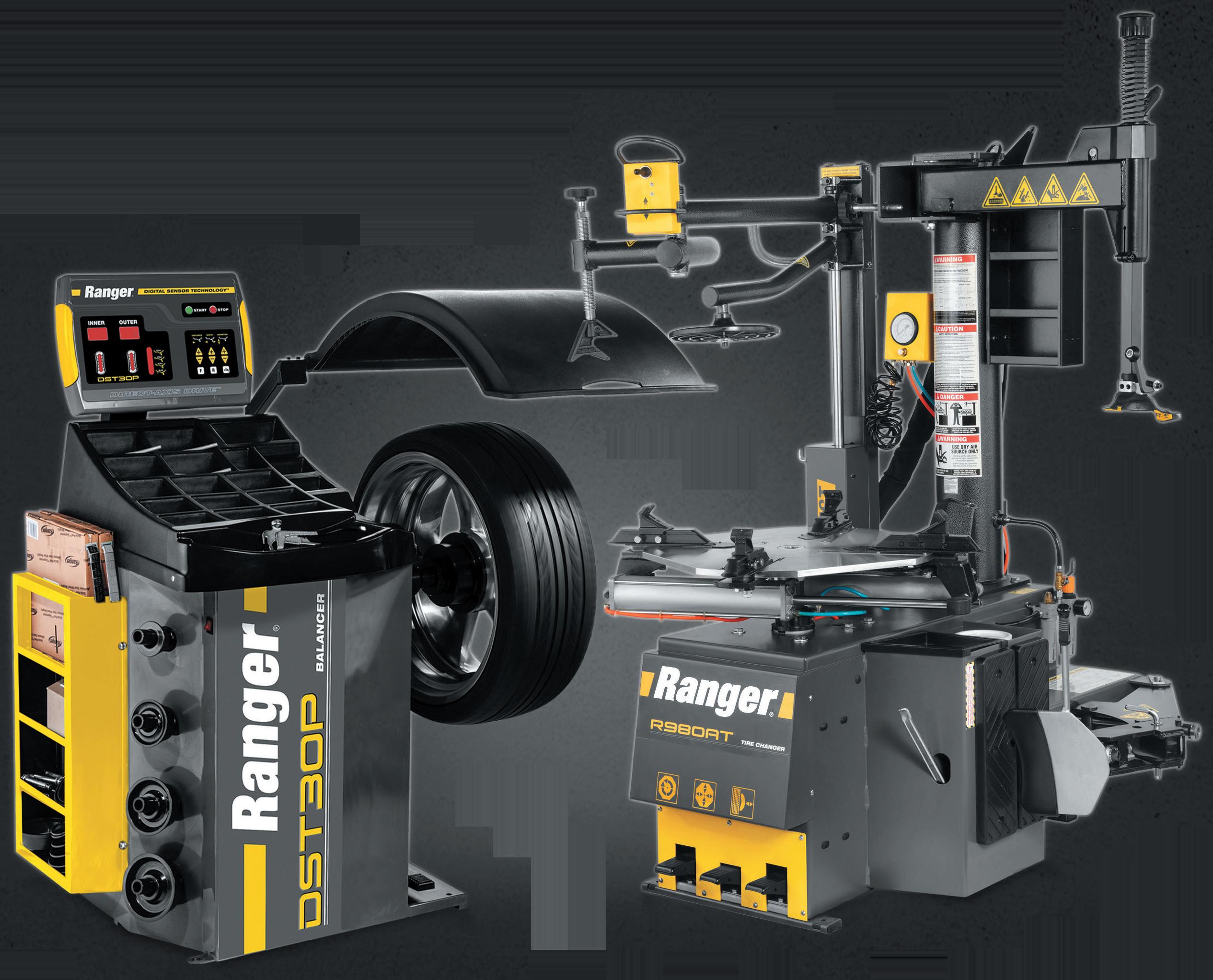


Two Machines. One Price. Limitless Performance. www.rangerproducts.com *Price valid until March 31st, 2024. **Free shipping to direct shipping points within the 48 contiguous United States only. © 2024 BendPak Inc. Ranger Products is a registered trademark of BendPak. Revolutionize your tire and wheel service center with the ultimate pairing of precision and efficiency. Our combos redefine the standard, bringing you cutting-edge features without the hefty price tag. Elevate your services, amplify your efficiency, and see a direct impact on your profits. Don’t miss out on this opportunity to upgrade your workshop to the next level of performance. Connect with us at 1-800-253-2363 to speak with our experts or explore our combo offerings at www.bendpak.com. Discover the innovation, efficiency, and satisfaction that only Ranger can deliver – brought to you by BendPak. Tire Shop Package Includes: (1) DST30P Wheel Balancer + (1) R980AT Tire Changer + (1) Tape Wheel Weights Blk. & Slv. 1400 PC. 24 Month Warranty OEM Approved Max Performance Free Shipping** RimGuardTM Wheel Clamps Forged Steel Foot-Pedal Controls High-Volume Storage Wheel Weight Dispenser Stay Hold Brake Pedal Precision-machined, Hardened-Steel 40mm Shaft Easy-to-Read LED Control Panel Auto Hood Start Adjustable Bead Breaker Power Assist Tower Swing-Arm Bead Handling Tools SPEED Tire Shop Package SKU# 5140127 $8,320* Model: DST30P Model: R980AT
AUTOMOTIVE PRODUCT GUIDE

Upgrade your air system
DanAmAir is a fast, flexible, and easy to modify aluminum pipe system for compressed air in any shop or garage. The Press-to-Connect fittings feature a full-bore design for turbulence free air delivery. Designed with simplicity in mind, DAA allows you to do-it-yourself. Measure, cut, de-burr, then simply Press-to-Connect. It adds up to lower installation times and cost. This pictured shop’s installation included a 40mm loop for their main line measuring 160’ by 70’, and 25mm drops/ branches for their booth and tool outlets.
SPONSORED


Industrial Nitrile Gloves
The PermaSafe Industrial Nitrile Gloves have a thickness of over 6 mils, with textured palms and fingers. According to PermaSafe, these gloves are designed to be thicker and more puncture-resistant compared to standard disposable gloves. Additionally, the gloves feature a textured surface, which provides an increased surface area compared to other disposable gloves of similar size. This design aims to improve grip and control, especially when handling wet or slippery objects. These gloves are hypoallergenic, as well as latex, vinyl, protein, powder, and BPA-free.


Prevents overtightening plastic/aluminum oil filter cannisters
The Lisle Corporation Torque Adapter 25 Nm, No. 61860, is designed to help prevent overtightening plastic and aluminum oil filter cannisters and filters. This adapter turns any 3/8” drive ratchet or breaker bar into a 25 NM torque wrench. Additionally, it can be used with a 21mm socket or wrench, but is not meant for use with impact or pneumatic wrenches.

Black phosphate tip will not chip
The Matco Tools 10-pc Top Torque II Screwdriver Set - Teal, No. SSPCTT10C features blades that are molded into the handle and have a wide forged butterfly in the end. Built from high-alloy German steel, the blades are rugged and designed to last, and the tip contains black phosphate that will not chip. The screwdriver’s three-sided ergonomic handles have a microfiber coating that provides an ideal grip even when hands are slippery with oil, grease, or perspiration. The set includes the following Phillips sizes: P2: 1/4” by 1”; P1: 3/16” by 3”; P2: 1/4” by 4”; P3: 5/16” by 6”; and P2: 1/4” by 7”, as well as the following slotted sizes: 1” by 1/4”; 3” by 3/16”; 4” by 1/4”; 6” by 5/16”; and 8” by 3/8”.

Snaps together for quick set up
The Wrench Pro from Ernst Manufacturing is designed to save space in the toolbox by storing wrenches upright, fitting more tools in a compact space. The modular design snaps together and pulls apart easily for quick setup and customization for any size wrench set and types, including offset, combination, open end, stubby, and ratcheting. Includes identification labels to see wrench sizes easily and to spot missing tools. Additionally, its cleats sink into drawer liners to prevent movement and magnetic options are available to provide an even stronger hold.


Lift height of 3-3/8” to 24-1/4”
The OEMTOOLS 3-Ton Long/Low Profile Jack, No. 24868, has a lift height of 3-3/8” to 24-1/4” and is ideal for low-profile vehicles, trucks, and SUVs. The 4.3” saddle with jack support pad and foam handle cover prevents damage to the vehicle. Nylon casters protect sealed surfaces and dealer showrooms. This jack weighs 100.3 lbs and is 31-3/8” long.
47 MOTOR AGE
AUTOMOTIVE PRODUCT GUIDE


Pairs with new or reman compressors
Four Seasons provides a variety of pre-packaged HVAC kits for applicationspecific coverage. Blower motor resistor kits, air door actuator kits, Pac-Kits complete A/C kits and Pac-Kits A/C service kits paired with a new or reman Four Seasons compressor are available.
SPONSORED


Features EVinsulated platforms
The Tuxedo Distributors iDEAL EV/Hybrid Lift Table, No. LT-EV2500AH-X incorporates multi-adjustable and directional EV-insulated platforms for controlled lifting and lowering tasks to safely remove, replace, or service heavy vehicle components for EV or hybrid vehicles, such as EV batteries, motors, powertrains, or similar heavy components. The table also features air-hydraulic power and fully operational hand controls for lifting, locking, and lowering. The table can hold up to 2,500 lbs.


886’ beam distance
The 1,200 lm Tactical LED Rechargeable Flashlight with Power Bank and Dual Power from Observer Tools is magnetic and waterproof. Included with the flashlight is a 3-in-1 charging cable (plug not included). On high, the light gives off 1,200 lm (500 lm on low, and 60 lm on ultra-low) and has a beam distance of 886’. The light has a run-time of 72 hours, a power bank, clip, and zoom functionality.


Positions both front and rear arms
The Thexton Lift Alignment Tool, No. 962, is designed to streamline the positioning of lift arms to vehicle lift points. With the capability to position both front and rear arms, the alignment tool minimizes the need for constant up and down movements, reducing strain on the user. Crafted with a lightweight yet robust design, this tool aims to ensure ease of handling without compromising durability. Equipped with two flush-mounted laser guides, it provides precise visualization of the outer edge of the lifting point. The laser guide features a twist-on/off mechanism and replaceable batteries. Designed to accommodate most lift pads up to 6.75”, the tool also comes with a magnetic hook for storage on the lift.

48 JUNE 2024
ORDER BY 6 PM FOR SAME DAY SHIPPING WRAP IT RIGHT COMPLETE LINE OF STRETCH WRAP COMPLETE CATALOG 1-800-295-5510 uline.com 2406MA_Uline.indd 1 5/2/24 9:51 AM
VIEW MORE PRODUCTS ONLINE


Remove stubborn fuel injector seals
The Ford Power Stroke 6.7L Fuel Injector Copper Compression Seal Puller and Seal Saver ProKit from ProMAXX is designed for technicians to remove stubborn fuel injector seals from the head effortlessly and securely. With a precision machined, replaceable threaded tip that grips and extracts the seal from the injector seat, this tool ensures efficiency and precision. The seal saver acts as a safeguard, preventing the seal from inadvertently dropping down into the valve cover valley. The kit has a knurled and hard-coated aluminum body.


Features ball and socket design

The IQ Vise from Work IQ Tools features a ball and socket design that allows articulation and 360-degree rotation at any angle. It also includes a Quick Cam compression lever in the front that gives the vise even more functionality by allowing it to lay flat, lock at any angle, or rotate for optimal work positioning. The eight-position IQ Lok locks the ball in place and allows up to 130 ft-lbs of torque. Additionally, five different IQ Vise Jaws allow users to tailor the vise’s grip for the project at hand.


Features 11’ long tube
The Vividia BD-5030i Borescope from Oasis Scientific is a semi-rigid USB borescope with a 0.19” diameter probe head and an 11’ long tube. It is equipped with both a front and side camera on the head and is designed to integrate seamlessly with the “USEE” Camera app (available on iPhone, iPad, and Android). Users can switch between both cameras and adjust their LED brightnesses within the app. Pictures and videos can be saved to connected devices.


Wireless connection and one-touch update
The i53BT Multi-System Tablet Scanner from Foxwell is a diagnostic scanner with wireless VCI Foxlink I and an Android 9.0 operating system designed to deliver OE-level diagnosis for different car brands. The scanner supports the most commonly required service and coding features. Additionally, the scanner can run bidirectional tests, supports CAN FD/DoIP, features wireless connection and a one-touch update, and automatically reads VIN.


VIEW MORE PRODUCTS ONLINE 2406MA_Topdon.indd 1 5/10/24 8:55 AM
Elevate Your EV Lifting Game
One of the things consumers like about electric vehicles is that they promise reduced maintenance. But “less maintenance” doesn’t mean “no maintenance,” and your EV customers still need your help with routine tasks like tire rotations, brake service, and filter changes. In fact, due to the nearinstant torque EVs offer, they may need new tires more often than their gaspowered counterparts.
Whether you’re doing a battery swap or just swapping tires, here are 5 tips for safely lifting an EV.
1. Use a lift with sufficient rated capacity. Thanks to their highvoltage battery packs, most EVs are heavier than their internal combustion engine (ICE) counterparts. Check the vehicle weight and make sure the lift you’re


planning to use has sufficient rated capacity to raise it for service.
2. Don’t guess at the lifting points . It’s critical that your frame-engaging lift makes contact with an EV only at the vehicle manufacturer’s recommended lifting points. Most EVs are designed with their battery packs under the vehicle. The battery packs are large – taking up most of the undercarriage – and heavy. As a result, the OEM-recommended lifting points are often on the far edges of the vehicle frame. Some two-post lift arms will not extend or retract far enough or have a low enough profile to reach these points. If your lift can’t reach the manufacturerrecommended lifting points, don’t put your safety at risk. Use a different lift.
3. Choose the right adapters. Flip-up adapters are convenient, but not precise. Stackable screw pad adapters can be adjusted up


or down to ensure level lifting and more precise and secure frame engagement. Gouge- and tearresistant polyurethane pads reduce risk of vehicle damage. Never use wood blocks or homemade adapters.
4. Make sure your lift platforms are long enough. Some luxury EVs have extra-long wheelbases. If you’re changing tires or doing other work where a mid-rise lift is sufficient, make sure the lift you choose has long enough frames or platforms to reach the manufacturerrecommended lifting points without contacting the battery pack.
5. Rock before you roll (or lift). If using a two-post lift, after the lift arms are positioned, raise the lift until just before the adapters contact the lifting points. Make sure the arm restraint gears on all four arms are engaged, and then raise the lift until the vehicle tires are a few inches off the ground. Stop and verify that all four adapters are making solid contact with the recommended lifting points. If they are not, lower the vehicle and start over. If the adapters appear to be making secure contact, gently rock the vehicle to make sure it is stable and balanced before proceeding.


ADVERTORIAL 50 JUNE 2024 ADVERTISEMENT
30440 Agoura Road Agoura Hills, CA 91301 (800) 253-2363 www.bendpak.com
BendPak’s revolutionary Mobi-EVS™ is a full-rise battery powered mobile scissor lift table that is perfectly suited for Electric Vehicle Service and EV Battery Pack replacement. With its compact design, this space-saving scissor lift can be easily transported anywhere in the workplace, making it ideal for multi-bay facilities or workplaces with confined areas. To learn more visit bendpak.com/evs4500


© 2024 BendPak Inc. All rights reserved. 1-800-253-2363 • www.bendpak.com LEARN MORE Push & Pull Handles Full-Floating Ball Bearing Slip Plate Deck Stowable Push-Pull Handle Twin Hydraulic
Remote Control 5" Diameter Zero-Throw Casters Manual Floor Locks Fore Storage Bin Battery Charge Indicator Aft Storage Bin Durable Powder Coat Finish 12-Volt Deep Cycle Battery w/ OnBoard Charger Adjustable Screw Jacks Dual Scissor Design Full-Length Utility Trays ELEVATE YOUR EV
STANDARDS Optional Adapters Available Battery-Powered Mobility Magnetized Hand Pendant Control Mobi-EVS™ • EVS4500 EV Battery Pack and Powertrain Lifting System 4,500 lb. CAPACITY
Cylinders
SERVICE


www.PerfectstopSummerPromo.com FOR OFFICIAL RULES, VISIT WWW.PERFECTSTOPSUMMERPROMO.COM. 2024 Aftermarket Auto Parts Alliance, Inc. No purchase necessary. Void where prohibited. Promotional images may not reflect actual prizes. Logos and trademarks are the property of their respective owners. WINNERS 6 Technicians enter for your chance to win the powersports vehicle of your choice and up to $25,000 with Perfect Stop®. $25,000 Also Giving Away, $25,000 in 150 ancillary gift card prizes ENTER FOR YOUR CHANCE TO WIN! STARTs JUNE 1st 2024 ENDs JULY 31st 2024 2024 GIVEAWAY
TECHNICAL SERVICE BULLETINS

MAZDA CRUISE CONTROL BRAKING
This bulletin applies to 2020-2021 Mazda CX-30 vehicles built before Jan. 19, 2021; 2019-2021 Mazda3 vehicles produced in Japan before Dec. 25, 2020, and 2019-2021 Mazda3 vehicles produced in Mexico before Dec. 29, 2020.
Some customers may complain about brake concerns when coming to a stop while following a vehicle using MRCC (Mazda Radar Cruise Control with stop and go function). Concerns may include harder braking at slow speeds just before a complete stop, the vehicle creeping toward the vehicle in front before coming to a complete stop and the “Depress Brake Pedal” warning appearing in the instrument cluster.
This is caused by improper control software of the DSC HU/CM. To eliminate the concern, software of
the DSC HU/CM has been modified. Reprogram the DSC with the Mazda Modular Diagnostic System (M-MDS), using the Mazda diagnostic and repair software (MDARS). After reprogramming, pending DTC P2610:00 may be stored in the PCM without the check engine light on. Since this DTC may turn to a current DTC depending on operations after the reprogramming, clear the DTC after all repair work has been done.
If DTC U2120:00 and/or U2500:82 are stored and the i-ACTIVSENSE amber warning light turns on after reprogramming, refer to SA-043/20. If the Welcome lamp function is accidentally activated while using MDARS, it may also cause this concern. Refer to SA-054/20.
Clear the DTC, turn ignition off and exit the vehicle. Close and lock the driver door. Wait for at least 10 minutes. Verify the repair by starting the engine and making sure that the check engine light is off and no abnormal warning lights are on.
CALIBRATION
Model File name
2019-2020 Mazda3 .......
2021 Mazda3 .................
2020 CX-30
2021 CX-30
(Photo: Mazda)
BCKA-4300F-F
BFVV-4300F-C
DFT5-4300F-F
DEJW-4300F-B

HONDA FALSE OIL PRESSURE
This bulletin applies to 2017-2018 Honda CR-V, 2016-2018 Civic with 1.5L engine and CVT, and 2018-2019 Accord vehicles with CRV.
The shift position indicator (D light) starts flashing due to DTC P2817 (shift solenoid valve O/P — pressure control solenoid H stuck off) may be set. When the TCM checks the drive pulley oil pressure, it misreads the pressure as high even though oil pressure is within specification. Update the PGM-Fl and TCM software. Use i-HDS software version 1.004.064 or later. (Photo: Honda)
CHEVY WEIRD CODE
This bulletin applies to 2018-2022 Chevy Colorado and 2015-2022 Equinox vehicles. The ABS/TCS MIL may be on, with DTC C0010.5A stored in the EBCM, with a possible OnStar
INFORMATION
COURTESY OF MITCHELL 1
VEHICLESERVICEPROS.COM 53 MOTOR AGE


notification. According to GM, there currently have been no cases of a functional concern regarding this DTC. If the C0010.5A is the only code stored, clear the code and road test. Advise the customer that this code can be caused by a three-point turn kind of maneuver. If the vehicle is still moving forward and the shifter is moved to reverse, this code can be stored. Have them make sure they come to a complete stop before shifting. (Photo: Chevrolet)


BMW KEY MISSING
This bulletin applies to 2020 -2022 BMW vehicles. A Check Control Message (CCM) may display a “vehicle key missing” warning after engine start. Several causes are possible when the key fob, with a good battery, is in the vehicle cabin:
• The key fob is not recognized due to its unfavorable location in the vehicle interior.
• Interference caused by radio antennas or high voltage power lines.


• Shielding of the key by metallic objects (mobile phone, wallet, etc.)
• Charging of mobile devices in the vehicle.
• Charging of the high-voltage battery (in battery electric or plug-in hybrid electric vehicles).
Program the vehicle using ISTA 4.31.1X or higher. Always connect a BMW-approved battery charger/power supply. (Photo: BMW)

FORD START/STOP GLITCH


Some 2020-2021 Ford Expedition vehicles may exhibit a no-restart during an auto start/stop operation. This may be due to a software parameter in the PCM. To correct the condition, reprogram the PCM using the latest software level in the Ford Diagnosis and Repair System (FDRS) scan tool. (Photo: Ford)
GMC VACUUM PUMP OIL LEAK
This bulletin applies to 2015-2021 GMC Canyon vehicles equipped with the LCV engine. A brake booster vacuum leak may occur noted by an

54 JUNE 2024 SCAN TO READ MORE TSB s ONLINE
Remove auto glass in minutes with the Inductor® Series: Glass Blaster This tool allows you to work from outside the vehicle with no need to remove interior trim. Release urethane in hard-to-reach areas where other glass tools can’t go, with no damage to the encapsulate or frit. e Ind www.theinductor.com 877-688-9633 Available through your local tool distributor. Home of the Original Mini-Ductor 2406MA_InductionInnovations.indd 1 5/8/24 11:07 AM
audible hiss noise. DTC C0299 may be stored. This may indicate the vacuum pump leaking oil into the booster. Inspect the inside of the vacuum hose and booster for a sticky substance on the rubber. If this is present it is an indication that the vacuum pump is leaking oil. Replace the pump and hose, along with the brake booster as needed. (Photo: GM)

AUDI DRIVE AXLE NOISE
This bulletin applies to 2018-2024 Audi A3, S3 and RS 3 vehicles, 2018 A3 Sportback etron, 2018-2019 A3 Cabriolet and 2019-2024 Q3 vehicles. A cracking noise may be heard from the front end when changing direction. When pulling away, there is a one-off cracking noise after changing direction. This indicates relative movement of the drive axle in the wheel bearings. Improved drive axles were gradually introduced in production.
Disassemble the affected drive axle. Apply liquid locking fluid P/N d 154100A1 around the threaded end as shown in the image. After assembling the drive axle, the vehicle must not be operated for at least eight hours to allow proper cure time. (Photo: Mitchell 1)
DODGE HEAT ISSUE
This bulletin applies to 2017-2018 Dodge Durango vehicles built on or before Aug. 28, 2018, and equipped

with a heated steering wheel. The customer may note that the heated steering wheel feature may turn itself off after approximately five minutes of operation. The easy fix: reprogram the HSM with the latest software.
(Photo: Chrysler)
LINCOLN
HEATED STEERING WHEEL
2017-2019 Lincoln Continental vehicles may exhibit an inoperative heated steering wheel. For vehicles equipped with adaptive steering, the steering

effort control module (SECM) controls the heated steering wheel feature and is internal to the steering wheel. For vehicles not equipped with adaptive steering, the heated steering wheel module (HSWM) controls the heated feature and is separate from the steering wheel. Using the OASIS tab, drop down > HVBoM > Features button or an appropriate Ford diagnostic scan tool, you can determine if the vehicle is equipped with adaptive steering. Refer to workshop manual section 211-05. (Photo: Lincoln)
If you have an original tool idea which others may need, Lisle Corporation is interested in evaluating your idea. Your idea may be produced and sold by Lisle Corporation under an attractive Award or Royalty Agreement that will bring you an income for years to come. If you have a new tool idea, follow these two simple steps:
1. Write Lisle and request an Idea Disclosure Agreement.
2. Return the signed agreement to Lisle along with your idea. Lisle Corporation will promptly evaluate your idea. You will then be notified whether or not Lisle will offer an award or royalty.
Award/Royalty Program Lisle Corporation
807 E. Main Street PO Box 89 Clarinda, Iowa USA 51632-0089
https://www.lislecorp.com/idea-program

VEHICLESERVICEPROS.COM 55 MOTOR AGE
The Innovator in Specialty Tools P.O. Box 89 ● Clarinda, IA 51632-0089 712-542-5101 ● Fax 712-542-6591 https://www.lislecorp.com/idea-program
TURN YOUR TOOL IDEA INTO MONEY LISLE CORPORATION CURRENTLY PAYS ROYALTIES TO OVER 100 INDIVIDUALS LEARN MORE HAVE YOU DEVELOPED AN AUTOMOTIVE TOOL? 2406MA_LisleCorp.indd 1 5/9/24 8:26 AM

TOYOTA
HV FUEL PUMP
Some 2018-2019 Toyota Highlander Hybrid (HV) vehicles may exhibit a MIL on with DTC P107B (fuel rail pressure sensor B circuit range/performance). To correct this condition, replace the fuel pump assembly using P/N 7702048260 or 77020-4861 (based on vehicle year) and fuel section tube set 77169-33030. (Photo: Toyota)
AUDI WARNING LIGHTS
in the power steering control module. This DTC is logged in the power steering control module because it does not participate in the data bus communication during the start procedure. The main fuse carrier may be the cause. When the engine is started, the voltage should not drop by more than 1 volt at contact 4 in the fuse carrier. This is the power supply to the power steering control module. If the voltage drops more than 1 volt, the fuse carrier must be replaced. (Photo: Mitchell 1)
NISSAN LEAF HOSE


This bulletin applies to 2016-2023 Audi TT/TTS/TT Roadster, 20162020 A3/S3, 2016-2019 A3 Cabriolet, 2017-2020 RS3 and 2018-2022 TT RS vehicles. Several warning lamps (ABS, TPMS, etc.) may be on sporadically when the engine is started (both manually and in start/stop mode). DTC B116831 (steering angle sensor no signal) may be stored in the ABS module. There is a voltage drop
This bulletin applies to 2017 Nissan Leaf ZEO vehicles. The vehicle may stop charging before a complete charge. The MIL may be on with DTC B2840 (power delivery module), P3170 (on-board charger) and P3171 (onboard charger). Also, the lower heat exchange coolant hose may be twisted or folded in such a way that prevents 100% coolant flow. The lower hose’s white alignment mark should be at the 12 o-clock position. Re-align the lower radiator hose and clear the DTCs.

SUBARU RUSTY STRUTS
This bulletin applies to 2017-2023 Subaru Impreza, 2018-2023 Crosstrek,
2019-2022 Forester, 2020-2023 Outback and Legacy and 2019-2023 Ascent vehicles. Customers may have a concern about surface rust accumulating in the top center retaining nut area of the front struts. The strut mount cap-seal shape has been changed and reinforced to provide improved sealing against water intrusion (outside diameter increased by 30mm, from 64mm to 94mm). The new design dust seals are available as P/N 20326FL001. The repair, if desired, involves thoroughly cleaning and the application of rust-preventative paint to the top steel portion of the strut mounts. Two recommended products include RustOleum “Stops Rust” spray enamel P/N 7779830 or Kryon “Tough Rust” spray enamel P/N K09202007. Remove the original dust cap and mask the area around the top portion of the strut mount. Use a wire brush to remove surface rust/debris, followed by 150180 grit Scotchbrite (green) abrasive pad. Blow the area clean. Wipe with mild solvent or a clean shop towel and allow to dry. Apply the anti-rust coating and install the new/larger dust seal caps. (Photo: Mitchell 1)


56 JUNE 2024 SCAN TO READ MORE TSB s ONLINE
A & E Hand Tools 37 Advance Auto Parts 60 Aftermarket Auto Parts Alliance 52 AUTEL ............................................... 41 BendPak 23, 29, 46, 50-51, 57 bproauto 5 Delphi Technologies 15 Ad Index DNJ Engine Components 19 Factory Motor Parts 2 Induction Innovations 54 Launch Tech USA .............................. 25 Lisle Corporation 55 Nissan North America 7 O’Reilly Auto Parts 21 Purolator Filters 31 Shurtape Technologies 9 TEXA USA .......................................... 43 TOPDON USA 49 TYC Americas 59 ULINE 48 Van Batenburg’s Garage 30 .................................... 59


H L FEEL THE ©2024 CoolBossTM. A division of BendPak Inc. All rights reserved. BendPak® is a registered trademark.*Your specific location may require a combination of multiple models and/or sizes to provide the most effective cooling experience. At Cool Boss, we focus on innovations that deliver incredible comfort and value. Every one of our COOLBREEZE™ and COOLBLAST™ evaporative coolers use tap water to instantly chill areas at a fraction of the cost of traditional air-cooling methods. Just plug them into a standard wall outlet, fill them with water, and instantly lower the surrounding temperature by as much as 26 degrees. It’s that simple! WWW.COOLBOSS.COM • 1-855-223-2665 A Division of BendPak Inc. Auto-refill 26˚F Cooling* Large Cooling Area Easy-to-use Control Panel Bring Indoor Comfort Outdoors Energy Efficient Warehouse Cooling Control Your Climate. Just Add Water.™ LEARN MORE dd Wa er. COOLBLAST SERIES COOLBREEZE SERIES
Sponsored by

NO. 149 The GateKeeper
BY BRANDON STECKLER // Technical Editor
TO THIS DAY, TECHNICIANS INDUSTRYwide have apprehensions about Secured Gateway (or SGW).
Fears like “SGW causes limited scan tool functionality,” and “We need factory-level tooling” are frequently shared.
With today’s connected vehicles, SGW was implemented (on 2018+ FCA vehicles and some 2020+ Nissans) to protect vehicles against infiltration from the outside world.
In 2018, two clever men were able to develop software to wirelessly sabotage (or “hack”) into a 2014 Jeep Cherokee. They did so without any added devices to the vehicle. The hack was carried about by infiltrating the vehicle’s connected infotainment system.
This infiltration allowed the hackers to take over the vehicle’s audio, windshield wipers, climate control, steering, powertrain, and braking systems.
This left the door open for hundreds of thousands of vehicles with the same connected infotainment system.
In 2018 FCA developed a device known as the Secured Gateway to prevent infiltration from the outside world. Just as it is described, it acts as a gate that opens and closes. It allows information to be accessed or restricted, via the DLC or infotainment system. Through technician and scan tool registration, access was granted for that individual using that scan tool (and tethered PC). This was at the OE/dealership level. For the aftermarket to have that same level of access a 12+8 cable was needed to bypass the SGW, requiring removal of the infotainment head unit for access. This was very time consuming.
Without authentication, the scan tool is left with limited functionality like scanning for powertrain DTCs and


monitoring live powertrain data. No bi-directional control, special tests, or even a DTC clear can be carried out.
A third party known as AutoAuth mimicked FCA’s model to provide that same level of security for the independent aftermarket shops/technicians (or IAMs). The same authentication process can now be carried out for the IAMs.
In this video, the Autel MS-Ultra is featured establishing connectivity to a 2022 Chrysler Pacifica Hybrid and a connection to the AutoAuth server via a WiFi connection. This allows the MS-Ultra to authenticate just as the dealer technicians do. More importantly for independent technicians, there is no longer a need to remove/bypass components for connectivity. With just a few key strokes, authentication is carried out in several seconds and full functionality of the MS-Ultra is available.


THE TRAINER 58 JUNE 2024 SIGN UP FOR YOUR FREE SUBSCRIPTION TODAY AT CONNECT.MOTORAGETRAINING.COM
SEE THE FULL SERIES OF THE TRAINER VIDEOS FROM MOTOR AGE ON YOUTUBE.


worldpac.com
worldpac.ca Access quality parts, technical training and business solutions all in one place. YOU’RE COVERED Worldpac stocks OEM parts for every situation.
|
