




TODAY I'LL PROVIDE YOU WITH A BIT of entertainment based on my recent experience. Everyone has at least one (usually multiple) tool chests/cabinets where you store your precious and beloved tools. I have a row of pro-level tool cabinets with multiple drawers (I’ll omit the brand.) The drawers are huge — 43 inches wide and 24 inches front to rear. I love my cabinets — strong, durable, reliable havens for my hand tools, precision measuring tools, piston ring compressors, scan tools, etc. One feature (I assume this is a safety feature) is that if one drawer is open, other drawers in the same cabinet won’t open. This is to prevent all drawers from being open at once and to avoid potential tip-over of the cabinet. However, when one drawer becomes accidentally jammed due to an object falling behind the drawer, this safety feature can prevent any drawers from opening. Well, that’s what happened to me.
One particular drawer was (embarrassingly) overloaded with loose objects. This is the drawer that ended up assigned to miscellaneous bags and boxes of fasteners and various odds and ends. A bag of 8x32 stainless socket head cap screws fell behind the drawer and effectively jammed the locking bar and prevented any drawers from opening. I know, shame on me for stuffi ng the drawer too full.
Among my four in-row cabinets, this particular cabinet houses six drawers, containing (from top to bottom) screwdrivers, pliers, snips and inspection lights; pushrod length checkers, light checking valve springs and degree wheels; -AN aluminum wrenches; scan tools; and an array of flaw detection tools, and the drawer with miscellaneous odds and ends. In the midst
of a job, I tried to open the second drawer only to discover that I was locked out. None of the drawers would open. Obviously, not a good thing. Since the cabinet is part of a four-cabinet system with a full-length workbench maple top, there was no practical way to pull this one cabinet out. We ended up using a slat of aluminum (1-inch wide x 1/8-inch thick x 36 inches long) as a “slim jim” to sneak between two drawers. We fi rst removed a drawer from another cabinet to study how the locking system worked. We then fished the slim jim between the fi fth and sixth drawers trying to engage the locking bar. It took about 30 minutes, but we fi nally succeeded in opening that drawer.
The offending drawer has since been emptied and re-organized, but I learned a hard lesson. Although I love my tools and treat them with respect, tossing miscellaneous bits and pieces into one drawer was a big mistake that I’ll never repeat. Imagine this happening in the midst of a job while the customer begins to fume due to the delay. Learn from my dumb mistake. Don’t treat your tool chest like a dumpster. One little mistake can bite you hard.
MIKE MAVRIGIAN EDITOR

Lesson learned from a tool chest mishap
Don’t treat your tool chest like a dumpster.






3515 Massillon Rd., Suite 200, Uniontown, OH 44685
(330) 899-2200, fax (330) 899-2209
Website: autoserviceprofessional.com


Greg Smith / gsmith@endeavorb2b.com (330) 899-2200, Ext. 2212
Editor: Mike Mavrigian birchwdag@frontier.com
Managing Editor: Joy Kopcha jkopcha@endeavorb2b.com
Associate Editor: Madison Gehring mgehring@endeavorb2b.com
Creative Services Director: Zach Pate

Art Director: Jonathan Ricketts

Graphic Designer: Emme Osmonson
Production Manager: Karen Runion krunion@endeavorb2b.com
Je Taylor, Diagnostics & Drivability Specialist
Bill Fulton, ASE Master Tech
Craig Van Batenburg, EV Technology
Chris Chesney, Repairify Jake Sorensen, McNeil’s Auto Care


Seth Thorson, Eurotech Automotive
Donny Seyfer, Seyfer Automotive
Bill Fulton, ASE Master Tech
Dan Thornton / dthornton@endeavorb2b.com (734) 676-9135, mobile (734) 626-4950
Bob Marinez / rmarinez@endeavorb2b.com (330) 899-2200, ext. 2217
Marianne Dyal / mdyal@endeavorb2b.com (706) 344-1388
Sean Thornton / sthornton@endeavorb2b.com (269) 499-0257
Kyle Shaw / kshaw@endeavorb2b.com (651) 846-9490
Martha Severson / mseverson@endeavorb2b.com (651) 846-9452
Chad Hjellming / chjellming@endeavorb2b.com (651) 846-9463
Vice President: Chris Messer
Sometimes, a vehicle owner may complain about unwanted ABS activation at low speed or non-ABS function when needed. During your check, you may nd that no codes are stored. The issue may be caused by corrosion at the wheel speed sensor(s) mounting surfaces. As an example, this appears to be a common problem with 1999-2002 Chevy/GMC vehicles such as Silverado, Sierra, Tahoe, Yukon, Suburban and Avalanche models, just to cite a few examples. The problem seems to be speci c to rust-belt states where corrosive materials are applied to road surfaces during winter months. If you suspect this problem, remove the wheel speed sensors and clean the sensor mounting surface on the bearing. Apply a rust inhibitor, then grease the surface and reinstall the sensor. Check peak-to-peak output voltage to verify the sensor signal.
If you encounter a 2007-2013 Volvo with hard-to-start or no-start issues, ask the customer if the concern seems to occur after the vehicle has been parked overnight.
During diagnosis, you may nd one or more codes stored:
• Code A (starting/engine does not start/engine turns)
• AD (starting/engine hard to start/cranks slowly)
• BJ (starting/engine does not start/unsure when/ at all times).
The problem may involve a defective “triple-valve” in the fuel pump, as the pump loses pressure as the engine remains o for several hours. Volvo has introduced an improved fuel pump under the same/previous part number.
A common issue with A/C systems is when the A/C clutch will not come on. Once upon a time, the diagnosis was fairly simple: check the pressures, check power at the low and high pressure switches, unplug and jump the suspect pressure switch to see if the A/C clutch comes on. It is not that easy anymore. There are many inputs that the powertrain control module (PCM) looks at to decide if it will allow the A/C clutch to run.
If the engine is running hot or if there is an engine mis re, the PCM will not allow the A/C clutch to come on. It monitors the throttle position sensor (TPS) and shuts down the A/C clutch if it detects a wide open throttle (WOT). It shuts down the A/C clutch if it detects that the idle is too low. These are all basic inputs that have been around for years.
In recent years, Ford has added additional inputs that can also shut down the A/C clutch. On some models, they have replaced the high pressure switch with an air conditioning pressure (ACP) sensor that actually measures refrigerant pressure instead of a basic pressure switch that opens up at high refrigerant pressures.
Ford has also added an A/C evaporator temperature (ACET) sensor. This sensor monitors the evaporator core temperature. If the PCM detects the evaporator core is freezing up, it will shut down the A/C compressor. Both the ACP sensor and the ACET sensor are highly overlooked, even though their data can be read on most scan tools. The ACET sensor may also be referred to as an evaporator air discharge temperature (EADT) sensor.
To test: Monitor both sensors on scan data. If your scan tool does not show the parameter identification (PIDs), use a voltmeter and monitor the sensor voltage at the sensor or preferably, at the PCM. If the ACET sensor voltage rises to 4.0 volts or higher, the PCM may interpret that the evaporator core is freezing up and will shut off the compressor.
The ACP sensor has a range of zero to 4.9 volts. Roughly speaking, 1 volt = 100 psi, 2 volts = 200 psi, 3 volts = 300 psi, etc. If the PCM sees high voltage from this sensor, again it will shut the A/C compressor down. If the actual A/C pressures are OK and the evaporator core temp is not freezing, suspect that one of these two sensors is preventing the A/C compressor from coming on.
When you run into a lack of communication with the module or modules you are trying to diagnose, this can be frustrating. In most cases, there are some simple tests that can be done to quickly determine why a module is not communicating.
Start with the basics. Check power to the data link connector. In many cases, Ford uses the same fuse for the data link connector and the cigarette lighter, so it is fairly common for that fuse to be blown. Power will always be on pin 16, the bottom, far right pin of the data link connector. Power loss will affect all of the modules, and if there is a lack of power to the data link connector, none of the modules will communicate.
If only one module has lost communication, test the communication circuits. There are many communication systems, but this only covers the standard corporate pro tocol (SCP) and the Controller Area Network (CAN). SCO is used in earlier model Ford vehicles with OBD-II systems. CAN is used on most current model year Ford vehicles, and we’ll only cover the high speed CAN here.
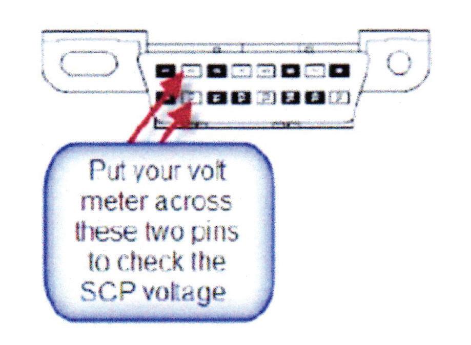
For a quick check of the SCP network, simply place your voltmeter across the SCP pins at the data link connector (top row, second from left and bottom row, second from left).
SCP voltage will usually range between 4.5 and 5.0 volts. If there is no voltage present at these pins when the key is on, unplug one module at a time until this voltage returns. In some cases, a shorted module will load down the network. If the voltage is low no matter what module is unplugged, there is likely SCP wiring damage. There needs to be at least one module plugged in to get the voltage on the network.
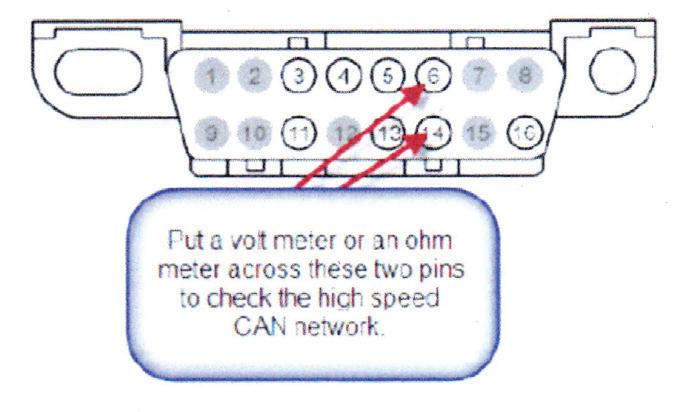
When testing the CAN network, both voltage and resistance can be checked. Place a voltmeter or an ohmmeter across pins 6 and 14 to check the high speed CAN network.
When checking voltage, the CAN network will normally be around 2.5 volts. When checking resistance, ensure the key is off. The resistance of the CAN net work will be around 60 ohms. An explanation of this resistance can help diagnose a high speed CAN problem.
On a Ford vehicle, there are two termination resistors on the CAN network. These resistors are usually found in the PCM and the instrument cluster. Each resistor is 120 ohms. When they are put together on the network, the network will show 60 ohms. With this in mind, if you check the resistance and it reads 120 ohms, you know that one of the modules is not on the network. Simply unplug the cluster or the PCM to see which one is on the network. A low resistance value will usually indicate a shorted CAN circuit, or a shorted CAN module. Unplug all of the modules except the PCM and the instrument cluster and then see if, at any point, the resistance returns to 60 ohms. A high resistance will usually indicate a connector issue, corrosion or wiring issue.
Place your voltmeter across these two pins to check SCP voltage.
Place the voltmeter or ohmmeter across these two pins to check the high speed CAN network.
Learn some tricks of the trade
TECHS HELPING TECHS IS TURNING 12 AND IT’S TIME FOR another roundup of useful tips and tricks courtesy of your fellow technician readers. While our writers share their expertise in every issue, it’s extra special when our readers share what they’ve learned from their days and nights working in the service bay. Thanks to all who shared their advice.
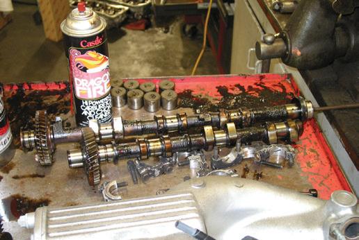
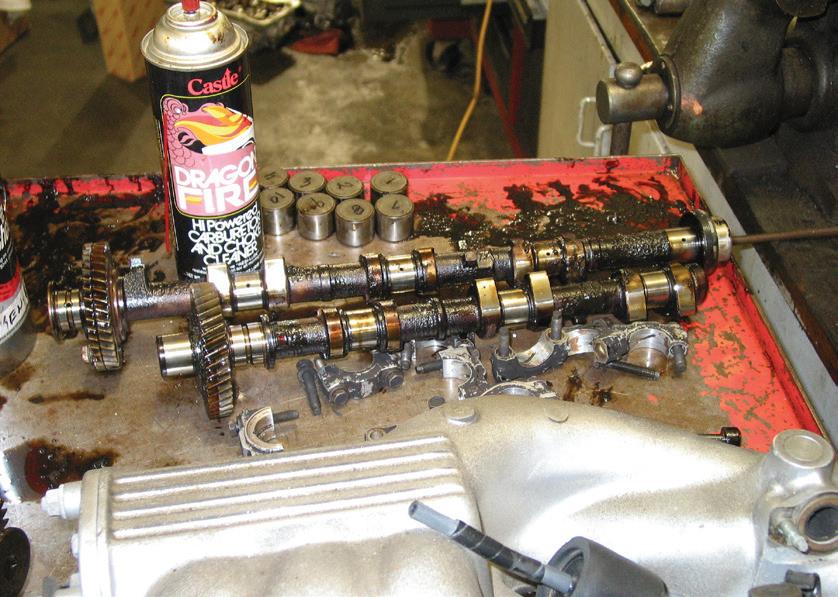
Whenever you’re dealing with a flat tappet camshaft or OHC lifter buckets, during disassembly, be sure to keep all lifters organized and marked relative to their specific cam lobe locations. This is important for inspection and diagnosis, as well as if you intend to re-use the cam and lifters. While it should be obvious that you can’t mix flat tappet lifters or bucket lifters (roller lifters don’t have this issue and can be inter changed), some folks forget the importance of keeping flat-tappet lifters organized relative to the cam lobes if you intend to re-use the cam and lifters. Mixing up used lifters can result in accelerated cam lobe wear.
 Russell Haslem RTC Performance
Never mix up lifters during disassembly, especially if you plan to reinstall them, as mating wear surfaces are matched at their respective cam lobes. Keeping lifters organized and labeled also aids in inspection of both lifters and individual cam lobes. (Photo: ASP)
We had a customer bring in a 2017 Buick Enclave, com plaining that he heard a clunk/thump noise on accel eration, but it only happened once after each key cycle. Initially we thought this might be coming from the suspension or engine compartment. Actually, this was being caused by the second phase power-up self-test of the ABS. The self-test begins when the vehicle is driven faster than 9 mph and when the EBCM has not detected any traction control or vehicle stability con cerns. This phase can be heard and felt by the driver. The system solenoids and ABS pump motor are com manded on and off to verify proper operation. This self-test noise is a normal action.
Brad Marvin Countywide ServiceWhen servicing any Chevy or GMC vehicles (2014-present) equipped with a 4.3L, 5.3L or 6.2L en gine, and the SES lamp lights up, accompanied by DTC P0106 and P0506, the cause may be a failed/broken valve spring. Remove the rocker covers and inspect the springs. If you find a broken valve spring, naturally you’ll want to replace it, but pay close attention first by finding out if the valve has dropped and possibly dam aged the piston and/or the block. If the valve hasn’t caused any damage, replace the offending spring. But also inspect the intake manifold to see if a runner has collapsed, in which case you’ll need to also replace the intake manifold.
The Ford 2.7L Ecoboost twin-turbo GTDI engine, as you know, is very popular among several Ford vehicle
models. They make decent power and torque (not as much as the 3.5L, but acceptable for most folks unless they’re doing a lot of towing). Each model year brings slight changes in any vehicle, but with respect to the 2015 2.7L, you may run into a MIL on with DTC P2450 stored in the PCM. If P2450 is the only DTC stored, take a look at the EVAP system. The fuel-tank-mounted EVAP blocking valve may be bad. You’ll likely need to remove the fuel tank to do this, and also disconnect the driveshaft. Be aware that the blocking valve part number differs between the standard size fuel tank and the 36-gallon extended range tank (standard tank takes P/N FL3Z-9F945-C; the larger tank takes JL3Z-9D333-D).
Bobby Young Deval AutoIf you’re dealing with a 2013-2015 Honda Crosstour equipped with a 3.5L engine (or any Honda engine featuring VCM (vari able cylinder management) rocker arms, the customer may com plain about a rattle noise and rough running. (The MIL may or may not be blinking when you inspect). Chances are very good that a VCM rocker arm pin is tapping against the adjacent rocker arm as it tries to lock the two arms together when trying to go into VCM. Or, the arms may be stuck together in the locked po sition (chances are the MIL will blink in this case). This may be intermittent, as the arms try to lock, lock or stay locked togeth er during engine operation, which can make diagnosis difficult. Refer to the service manual for the procedure on VCM rocker arm test. Once you find the culprit, simply replace the stubborn rocker arm(s).
Ely Roberts Grand Service CenterWhen dealing with a Ford 5.4L 3-valve V8 (2004-2005, as an example), the customer may comment about a rough idle and/ or intermittent misfires. Of course, lots of areas could be the problem (fuel injectors, ignition, etc.), but the VCT (variable valve control) could be the issue. Even if there are no DTCs that direct you to the VCT, that system could still be the cul prit. First off, before you delve into deep diagnostics, check the engine oil level and quality. Low oil level and/or contaminated oil could be the root cause that resulted in VCT issues. Is the
engine making a noise or rattling? With the engine off, disconnect the VCT solenoid connector and then start the engine. If the noise goes away or changes, this indicates a VCT problem. If you suspect the VCT, connect IDS and check PIDs for both banks with the engine at normal temperature. It should be in closed loop. VCT advance error pitch should hover around zero degrees. (A variance of plus or minus 5 degrees is OK.) The pulse width modulation should be the same on both banks. In open loop, the system should be dis abled. Even with sufficient oil in the sump, if oil pres sure is insufficient, there may not be enough hydraulic pressure to work the VCT (indicating a bad oil pump or more likely sludge buildup restricting oil passages). Make sure the engine is at full temperature when you check oil pressure, and be sure to use a good pressure gauge when checking.
Mike Hallinger Mike & Dale’sWe recently worked on a 2010 Chevy Cobalt equipped with a 2.2L engine. The transmission was experienc ing a hard shift going into third gear. A scan showed DTC P1810 (transmission control module cannot de termine correct line pressure). Scan data showed that the transmission fluid pressure switch signal C (or ange wire from the TCM to the transmission) was low (grounded when it should read high). We back-probed signal C (orange) and B (blue) with a multimeter on DC volts and monitored circuit voltage while moving the shifter. The orange wire should show battery voltage in Park and Drive. The blue wire should show battery voltage in Park and Reverse. At all other times, these circuits should be pulled low. In our case the signal C (orange) was pulled low all of the time. We unplugged the transmission connector and the circuit did not go high. We found the orange wire was shorted to ground next to the oil filter housing (very sharp edge here). We repaired the shorted wire and relocated the har ness away from the oil filter housing. We cleared the codes, conducted a test drive and verified the repair.
All vehicles on the road share a common component that allows them to pivot and keep the ride smooth: the ball joint. Removing and replacing ball joints is a common enough repair, especially with customer complaints of excessive road noise or tire wear.
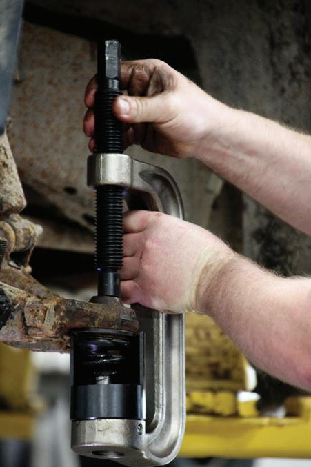
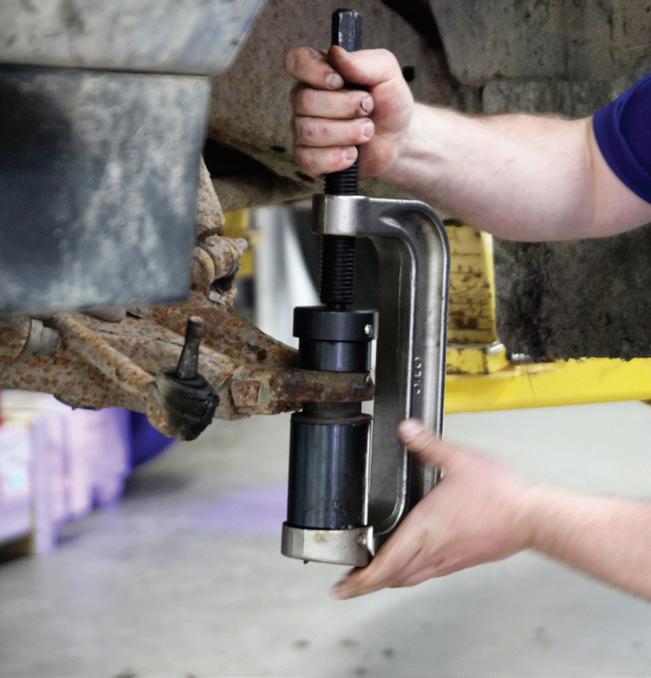
Ball joint presses make quick work of removing and installing press-fit parts such as ball joints, universal joints, and truck brake anchor pins. However, traditional ball joint service kits can be frustrating when trying to setup on an angle or in tight spaces. The problem occurs when the reaching at extreme suspension angles. Here, the cups and adapters tend to slide off the C-frame and onto the floor—requiring extra time needed to pick them up and start over.
OTC’s ball joint kit, the CA7149 Connected Adapter Ball Joint Starter Kit, features cups and adapters that click into place on the C-frame. No matter how the tool is held, or which angle it’s being used, the cups and adapters stay locked into position. Since the ball joint nests inside the connected adapters for one-hand setup, one free hand can be used to tighten the forcing screw by hand or with an impact gun. This also makes under-vehicle and on-bench work easier, as the cups and adapters stay locked into the C-frame, no matter if held vertically or horizontally.
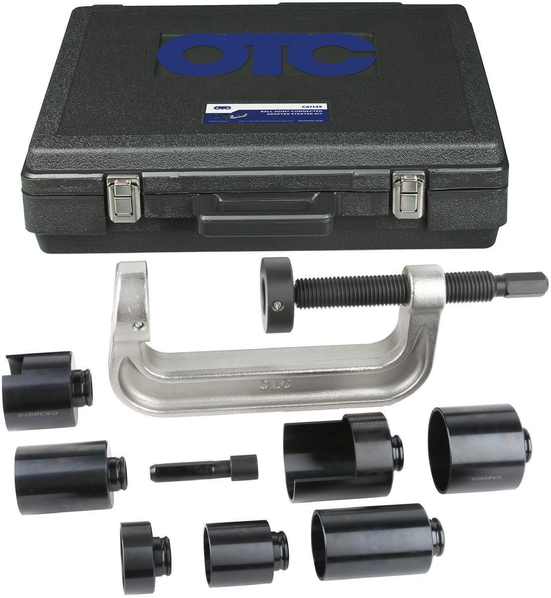
Why would a shop want to use the Connected Adapter Kit? It boils down to versatility and ease-of-use. The extra-large C-frame works on large and small vehicles on more than 600 vehicle applications, from a Honda Civic up to an F-550. The tool is backwards compatible with most cups and adapters that techs might already have and is fully compatible with OTC ball joint cups and adapters. For ball joints, u-joints, and wheel studs, the CA7149 Connected Adapter Ball Joint Starter Kit makes removal and installation faster and easier than before.
Bosch Automotive Service Solutions
28635 Mound Road, Warren, MI 48092 USA
Customer Service: 1-800-533-6127
Tech Service: 1-800-533-6127 Email: inquiry@service-solutions.com
KEEPING THE INTERNAL COMBUSTION engine as close to the stoichiometric ratio as possible will result in optimum catalytic converter efficiency and fuel economy. The stoichiometric ratio simply means that all the air (14.7 parts) and fuel (1 part) going into the cylinders are being converted to water and carbon dioxide exiting the exhaust. This is the perfect combustion reaction, but this desired stoichiometric operation can’t happen without fuel control.
Engine fuel control or closed loop operation is conducted by using the real time data from the oxygen or Air Fuel Ratio (AFR) sensors (and many other engine sensors) that are measuring and reporting the oxygen level that is in the engine’s exhaust gas stream. When the Powertrain Control Module (PCM) gets this exhaust oxygen level data it will adjust the amount of fuel that the engine gets, always trying to keep as close to stoichiometric as it can.
The oxygen or AFR sensor isn’t really measuring the amount of oxygen in the exhaust gases. Rather, it
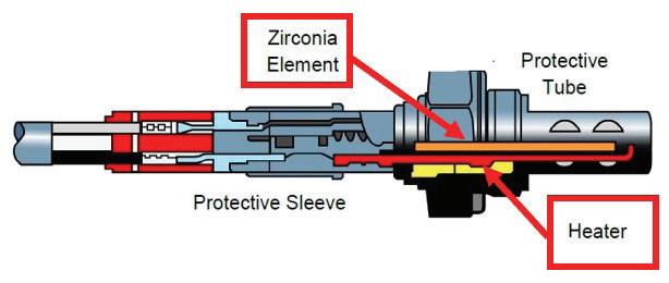
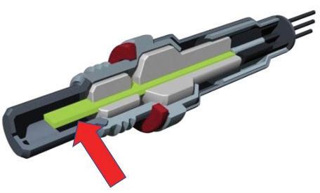
This cut away of a wideband AFR sensor shows the ceramic sensing element (red arrow) that will be used to compare the amount of oxygen in the exhaust to the outside air.
This is a picture of the wideband AFR. Note the shape of the ceramic sensing element.
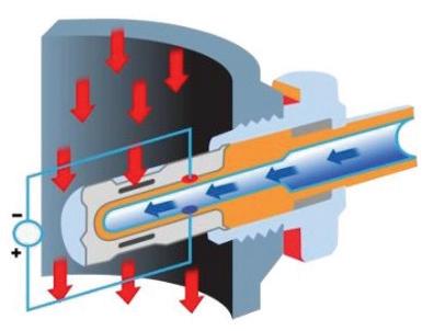
The red arrows show the exaust flow across the porous precious metal coated O2 sensor tip. The blue arrow represents the fresh air that will be used to compare the amount of oxygen in the exhaust by diffusion.
This oxygen sensor shows the diffusion area, where the exhaust gases are flowing, and the ambient air is contained.
is measuring the difference in the amount of oxygen in the exhaust versus the amount of oxygen in the air. (We will cover this better in a bit.)
Today’s oxygen sensors or the more common AFR ratio sensors are very efficient at measuring the amount of oxygen that is in the exhaust system and providing that information to the PCM that will make the needed adjustments to the amount of fuel that it is supplying to the engine. The technology has progressed to the point that the PCM can adjust the amount of fuel that each individual cylinder is get ting (Individual Cylinder Fuel Control or ICFC). If one specific cylinder has been over or under fueled, the PCM will adjust the fueling, specifically compen sating for that cylinder’s fueling needs.
The main difference between an AFR sensor (often called “the wideband sensor”) and the standard oxy gen sensor (often called the “narrowband sensor”) is their operational sensing range. The AFR sensor can detect a much wider and leaner range of fuel mixtures. This larger sensing range enables better fuel control over a much wider engine operating condition.
Today’s AFR sensors are capable of reporting ex haust oxygen levels (a reflection of fuel mixture) un der wide open throttle or very lean burning cruise operations, something that the earlier oxygen sen sor was simply not capable of doing. Keeping the fuel control as close to stoichiometric as possible allows the catalytic converter to function at maximum effi ciency, improving emissions, but this stoichiometric operation also ensures the best fuel economy as well. This wider spectrum of operation is why the AFR is now the preferred exhaust sensing device. But the standard oxygen sensor is still being used to check the oxygen storage capabilities of the catalytic con vertor, and in many cases these “catalytic convertor monitor” oxygen sensors are being used to fine-tune the engine’s fuel mixture to maximize engine and catalytic convertor efficiency.
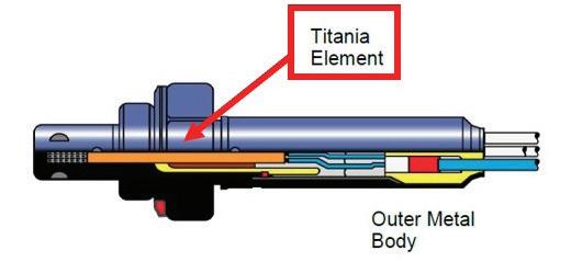
The simplest oxygen sensor uses a porous ceramic sensing element with a platinum covered area for oxy gen detection. The Titania sensor uses a porous ce ramic sensing element made of titanium dioxide and platinum-coated detection areas. The Zirconia sensor uses a Nernst cell for oxygen detection. The Nernst cell is made up of a porous zirconium oxide ceramic
sensing element and platinum-coated detection areas. The common wideband AFR sensor is going to use a combination of devices; a Nernst cell and a pump cell to detect and report oxygen levels in the exhaust.
The common part of these oxygen and AFR mea suring devices is the fact that they are all using a process called diffusion. This diffusion takes place across the porous, precious metal coated ceramic sensing element and allows the comparison of the oxygen content of the outside air to oxygen content of the exhaust gases.
The porous sensing element that allows the diffu sion must be kept free of debris and contamination for it to accurately detect the difference in oxygen levels. If the surface of the sensing element becomes coated or contaminated with a foreign substance it will become poisoned or suffocated and will no lon ger allow proper oxygen diffusion. As the sensing ele ment chokes, the sensor’s output will become slower, lazy, and less accurate and over time eventually will fail completely. But a poisoned sensor isn’t the only frequent cause of death for an oxygen or AFR sensor. The internal heater can also fail. For proper oxygen and AFR operation the sensing element must be kept hot. The sensing element is heated by an internal electrical heater to a functional temperature of 600 F (316 C) to 665 F (350 C) for sensor operation.
The PCM is constantly watching the oxygen and AFR sensor output for fuel control information. The PCM will be looking at the data that it is receiving from the oxygen and AFR sensors and comparing it to preprogrammed data to ensure the oxygen and AFR sensors are supplying accurate data. The PCM knows how much air the engine is consuming, how much fuel it has added and what range of values it expects to see from the oxygen, or AFR mounted in the exhaust. The PCM also knows what the resis tance value and current flow of the oxygen and AFR heater circuits should be, so it will be keeping an eye on those values too. If any of these values or param eters go too far out of range for too long, a Diagnos tic Trouble Code (DTC) is going to be set and turn on the Service Engine Soon (SES) light on the dash alerting the driver of the issue.
There are many oxygen and AFR OBDII codes and manufacturer-specific codes for slow, insufficient,
This cut away of the porous ceramic sensor element shows the precious metal coating. If the ceramic core gets contaminated it will not be able to function properly.
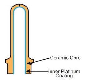
Here’s a close-up of the porous ceramic tip and the precious metal coating of an older oxygen sensor.
heater circuit or stuck rich or stuck lean codes. A P0134 - Oxygen Circuit No Activity Detected (Bank 1, Sensor 1) or P0133 - Oxygen Circuit Slow Response (Bank 1, Sensor 1) are examples of OBDII codes that could eas ily be caused by oxygen or AFR sensor contamination.
The 2016 Dodge Grand Caravan 3.6 V6 commonly displays manufacturer specific P219A Air Fuel Ratio Cylinder Imbalance Bank 1. This code is being set be cause the AFR sensor can detect and look at the in dividual exhaust pulses from each cylinder on Bank 1 using ICFC. It has detected a fuel control imbal ance of 15% between cylinders. This P219A code can be associated with bad or dirty fuel injectors or a bad camshaft, two issues that are common on the 3.6 V6 Caravan. The 2019 5.3 and 6.2 V8 GMC pickups may display a P015B: Oxygen Sensor Delayed ResponseLean to Rich (Bank 1 Sensor 1). This DTC can be set on some trucks because of water intrusion into the oxygen sensor harness connector, smothering the fresh air side of the AFR sensor element.
Oxygen and AFR heater failures are common on higher mileage vehicles but so is the poisoning or con tamination of oxygen and AFR sensors. Frequent causes of oxygen and AFR contamination come from the soot of excessively rich mixtures or heavy engine oil con sumption. Silicates in the engine’s coolant system can
This shows a greenish color on the protective case of this oxygen sensor. It was contaminated with traditional green antifreeze by a leaking head gasket.
This protective sleeve shows the coating of an oil burning Hyundai engine. The car needed a replacement engine to solve the oil burning issue.
This oxygen sensor has a bad heater. Notice that the case is black and reddish (normal) and the fuel control was OK.
This AFR sensor is heavily coated in carbon and was from a vehicle that had a leaking fuel injector and ran rich all the time.
leak internally into the engine and reach the exhaust and the oxygen or AFR sensors. RTV sealers with high levels of silicone and silicone sprays used in the engine compartment will quickly poison an oxygen or AFR sensor. Engine oil additives that have heavy metals de signed for lubrication qualities such as lead, zinc mag nesium and phosphorus can suffocate the sensor tip if oil consumption is excessive. The GF-6 oils that are used today and many of the long-life coolants that are used have dropped many of these detrimental components. Certain gasoline additives, especially octane boosters, have also been known to contaminate the sensor tip of the oxygen and AFR.
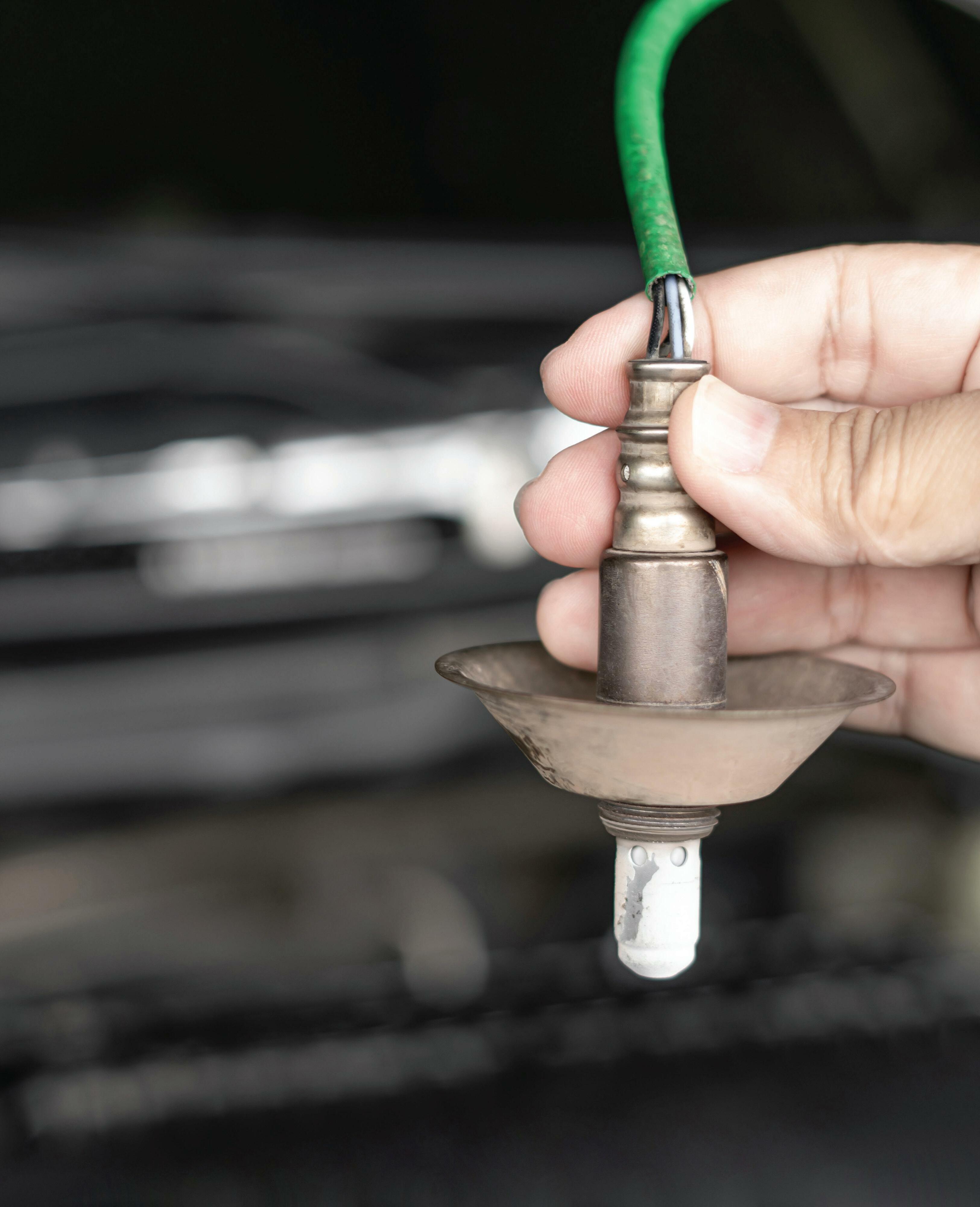
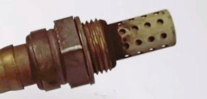
Reading what the exterior of the oxygen sensor tip shows when removed from the exhaust system can of ten point to an issue that hasn’t yet been identified.
1. Look at the exposed sensor shield for unusu al colors — green, yellow or an orange tint are often indications that the engine has an internal coolant leak. The coolant leak will need to be found and repaired before a new sensor is installed. In most cases, all the ox ygen/AFR sensors will have sustained dam age and should be replaced. Exterior engine coolant leaks can also affect the oxygen/AFR sensor operation if the coolant leaks into the sensor’s comparing area, contaminating and poisoning the sensor. Some Nissan 4.0L V6 Xterra and Frontier models have a heater control valve that will leak coolant directly into the high temperature protective sleeve (outside of the sensor) of the AFR harness, filling it with coolant, killing the sensor.
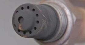
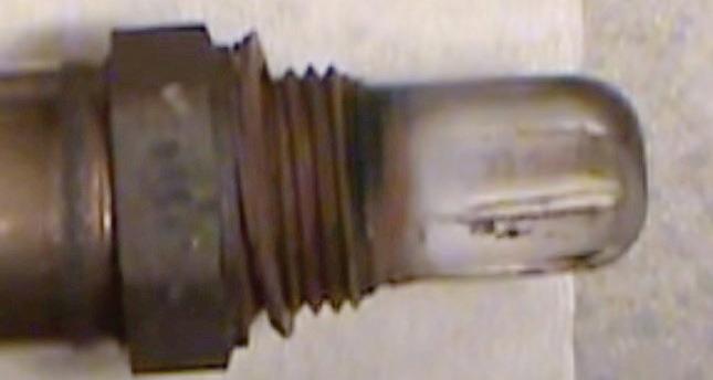
2. Silicone poisoning is a common issue on en gines that have been repaired and resealed using either too much sealer or the wrong type of sealer. The results of this type of oxygen sensor contamination typically will show up as a white powdery substance on the exposed sensor shield. Only use sealer that is designated as “sensor safe.” Used car deal ers that apply vast amounts of silicone-based “shine spray” to the under-hood area of a used car commonly create another source of silicone contamination.
3. Excessive oil consumption often will coat
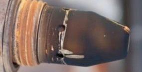
the exposed sensor shield with a sooty, gray ash color, but the exposed sensor shield isn’t the only area where oil can affect the oxygen sensor. Exterior oil leaks from valve covers or other gaskets can allow engine oil to contaminate the high temperature protective sleeve. The leaking oil can block the sensor’s fresh reference air opening.


line and setting codes P0172 (rich condition) and P2196 Oxygen Sensor Signal Biased/ Stuck Rich Bank 1-Sensor 1.
• 16" LENGTH ALLOWS INCREASED ACCESS FOR HARD TO REACH AREAS


•
•
4. A black, greasy, heavily carbon-covered exposed sensor shield is often a sign of an extreme rich mixture or over-fueling issue. Leaking injectors, purge control issues, leaking high pressure fuel pumps, biased MAP sensor signal or a badly neglected clogged air filter can cause this issue. The 2015 1.6L Ford Escape EcoBoost engine has experienced issues with the high-pressure fuel pump leaking during the pressure stroke into the valve cover area, filling the crankcase with gaso-
The PCM will do everything in its power to keep proper and correct fuel control. It wants to protect the catalytic convertor and produce the fewest tailpipe emissions, while still supplying the best engine operation and fuel economy for the driver. But for the PCM to do this, it needs exact exhaust gas oxygen levels to adjust the engine’s fuel control, and it relies heavily on the proper non-suffocated, non-contaminated oxygen or AFR sensor to provide this information.
Je Taylor boasts a 30-plus-year career in the automotive industry as a fully licensed professional lead technician. Je works for the CARS Training Network Inc. in Oshawa, Ontario, Canada. He is also heavily involved in government focus groups, serves as an accomplished technical writer, and he has competed in international diagnostic competitions as well as providing his expertise as an automotive technical instructor for a major aftermarket parts retailer.
When your job includes working under thousands of pounds of steel, you shouldn’t get complacent about your safety. Here’s a refresher of 10 tips to help you stay safe when using a car lift.

1. Read the directions. When you get a new lift or start using a different one, take a few minutes to review the manual, safety stickers, and warnings. Make sure you understand how all the safety systems work.
2. Only trained operators should use a lift. For everyone’s safety, keep customers and untrained personnel away from the work area.
3. Don’t invent your own lift uses or adapters. Lifts are professionally engineered to support their rated load capacity when vehicles are picked up as designed, using only recommended adapters. Using the lift in other ways, like only lifting one end of a car or using wooden blocks instead of the OEM adapters, is asking for trouble.
4. Keep your bay clean and well lit. Cluttered, dim work areas invite injuries.
5. Never override self-closing lift controls. Most professional lifts have controls that will stop running if the operator lets go of them. This is an important safety feature designed to ensure the lift only moves with someone at the controls to make sure the vehicle remains stable. Don’t risk a car falling just so you can step away for 30 seconds.
6. Always engage the safety locks/latches before getting to work. Review the manual for directions on how to place your lift on its mechanical load-holding devices (locks or latches) before going under it. On many lifts, you must raise the vehicle and then lower it onto the locks, releasing hydraulic pressure.
7. Check over your lift. Make it part of your routine to regularly check your lift for damaged parts and components, worn out adapters, etc. Don’t use a lift if any component is damaged.
8. Take care of your equipment. Follow the maintenance and lubrication guidelines in your lift’s manual to keep the lift running properly. Get it inspected annually by an ALI Certified Lift Inspector.
9. Keep it dry. To reduce risk of electric shock, most lifts should not be used on wet surfaces or exposed to rain.
10. Protect yourself. Wear safety glasses. Stay alert, use common sense, and pay attention to what you’re doing—and what the vehicle on the lift is doing. Put your safety first.
BendPak
1645 Lemonwood Dr. Santa Paula, CA 93060 (800) 253-2363
Bendpak.com










THE PROCESS OF SUPPLYING AIR TO the internal combustion engine’s cylinders is called aspiration, and it involves the induction or intake system of the engine. Engine aspi ration takes two forms: naturally aspirated (NA) or forced induction. The NA engine is relying only on atmospheric pressure to fill its cylinders with fresh air. When the NA engine’s pistons travel down during their intake strokes, they create a partial vacuum, and atmospheric pressure will push the air into that void.
The forced induction engine will use some form of mechanical means to force more air into the cylinders than atmospheric pressure will provide, and that extra air mass will increase the effective engine compres sion ratio. The forced induction system will use either turbocharging or supercharging to push or force more air into the cylinders than atmospheric pressure alone
will supply. This raises the pressure of the induction system above atmospheric pressure, resulting in bet ter fuel economy (under normal operation) and in creased engine power output.
The forced induction system achieves these im provements by forcing the same amount of air into a small displacement engine that a large NA displace ment engine would normally consume. This is one reason the manufacturers are leaning heavily on the forced induction system on today’s models even when they are hybrid equipped models.
This does not mean that the NA engine is going away anytime soon. Improvements in the NA induc tion system have advanced the efficiency of this type of induction, and they are continuing.
The use of a plastic intake manifold is now the norm
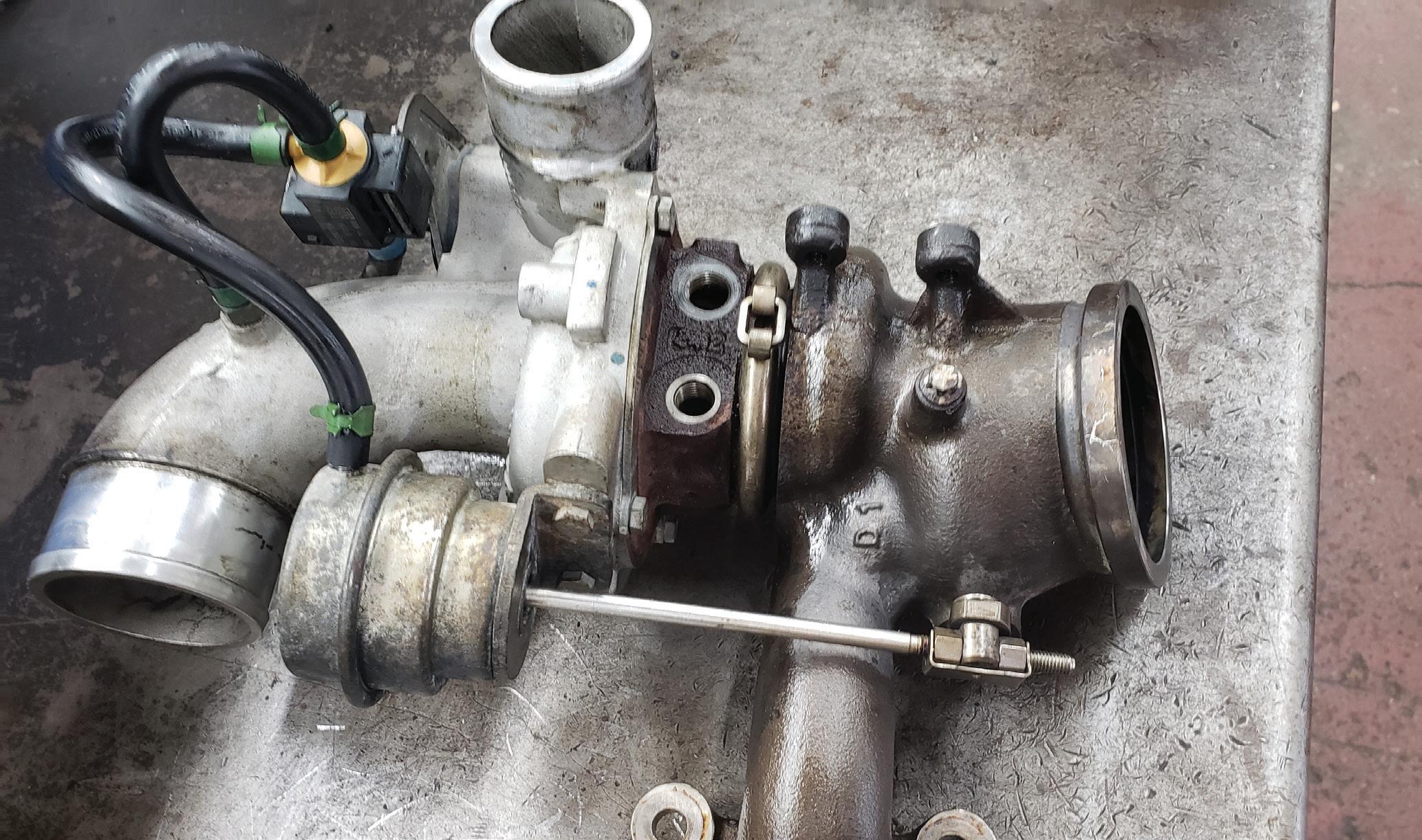
The turbocharger is the most common form of forced induction used on today’s vehicles.
on both the naturally aspirated and turbocharged en gine. The plastic intake manifold is used to evenly dis tribute the intake air via equal length runners to each intake port on the engine’s cylinder head.
Plastic intakes are cheaper to manufacture and lighter than the older metal intake design. The plas tic intake manifold slows the transfer of the engine’s heat to the intake air, allowing the intake to supply a cooler, denser (more powerful) air mass to each of the engine’s cylinders. A distinct advantage is the smooth uniform interior surface of intake runners which de livers a less turbulent airflow to each cylinder and that translates to more power. Engine power, torque and fuel efficiency can be improved by using variable length intake manifold runners, air tumbling features or by varying the size or dimensions of the intake ple num. These features are easily achieved during the molding process and accomplished using the plastic
intake manifold all while maintaining the required en gine packaging size. But these increases in power and efficiency do come at a cost. Plastic intakes tend to be noisier, and some earlier designs lacked the strength and durability of their metal predecessors, but most of these issues have been addressed.
The turbocharger is the most commonly used form of forced induction found on today’s vehicles. The use of a turbocharger on a small displacement engine, for example, a 2.0L 4-cylinder engine can create the same power output as a 3.0L V6 engine with 20-40% better fuel economy.
There are two common turbocharger designs used today: the single-scroll or the twin-scroll. The typical turbocharger will provide a boost pressure of between 6 and 8 psi.
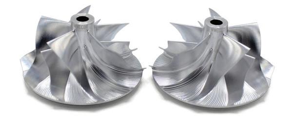
This compressor impeller design details can be seen in this photo, and you can easily see the difference between the exhaust turbine from the previous photo. The blades are carefully designed to optimize the intake airflow and reduce turbulence.
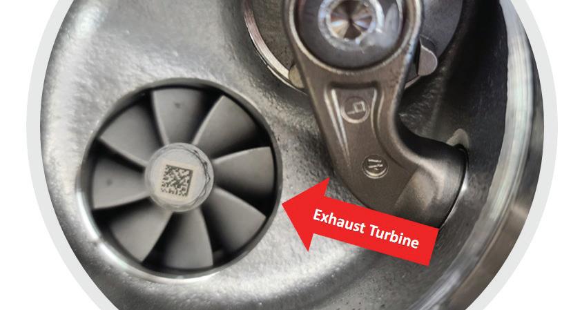
The turbocharger’s turbine is propelled by the hot exhaust gas flow (thermal energy), that drives the com pressor, forcing more air into the induction system. The turbocharger is not mechanically driven by the engine, so the increase in power and engine efficiency is provid ed without adding extra mechanical strain to the engine.
A downside of the turbocharging system is turbo lag. This lag is created by the delay time (about one second) it takes for the engine to create enough exhaust pressure to spin or “spool up” the turbocharger turbine. Turbo lag is most noticeable at low speeds and low RPMs.
Manufacturers are looking for a linear power deliv ery from their engines and do not want customers to experience turbo lag.
Complex, three-dimensional, spiral-shaped turbo charger compressor wheels have been designed, opti mizing induction air speed, pressure and temperature all while limiting turbulence formation. Turbulent air flow in the compressor area of the turbocharger will reduce efficiency and exaggerate turbo lag. Manufac turers have favored the use of a smaller turbocharger or multiple small units on V6 / V8 engines to lessen the turbo lag affect. Smaller turbochargers employ a small lightweight compressor wheel, with less inertia, which will spool up faster, reducing lag.
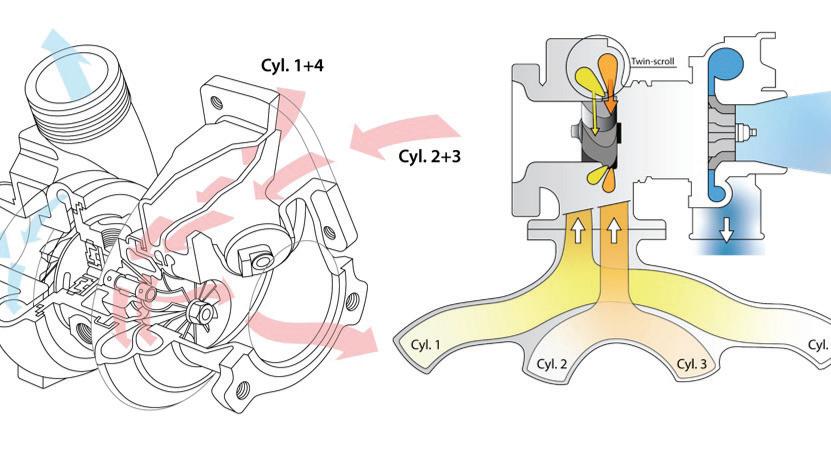
The single-scroll turbocharger with its single ex haust turbine inlet can in some cases allow cylinder exhaust pulses to interfere with each other, limiting its efficiency and exaggerating turbo lag.
Using the twin-scroll turbocharger design (effec tively two small turbochargers in one housing) all but eliminates turbo lag by using two separate exhaust gas flow turbine inlets. The twin-scroll design separates the exhaust cylinder pulses that interfere with each other reducing turbocharger and engine efficiency.
Examining the exhaust stroke cycles of the common 4-cylinder engine with a 1-3-4-2 firing order, when No. 1 cylinder is ending its power stroke and just opening its exhaust valves, No. 2 cylinder’s exhaust valves are still open (valve overlap). On a single-scroll turbocharger equipped 4-cylinder, the exhaust gas pressure pulse from No. 1 cylinder is going to affect No. 2 cylinder’s ability to expel its exhaust gases, due to exhaust rever sion. Exhaust reversion is the flow of exhaust gases back into the cylinder.
The twin-scroll turbocharger design reduces this exhaust reversion issue by pairing mating cylinders No. 1 with No. 4 to one individual turbocharger turbine in let and cylinders No. 2 with No. 3 to a separate distinct turbocharger turbine inlet.
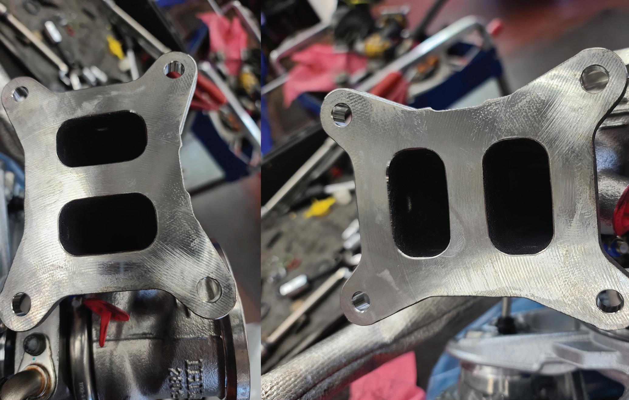
It’s important to note the twin-scroll turbocharger is employed on some inline 6-cylinder engines, again pairing the mating cylinders into common turbine in lets. BMW does this on their 6-cylinder engines. BMW refers to their twin-scroll turbocharger equipped en gine as the “BMW TwinPower Turbo.”
When combined with a specifically designed in take manifold and active valve train control, the twinscroll turbocharger provides more effective exhaust gas scavenging, allows for greater engine valve over lap, improves turbocharger efficiency, and provides
The twin-scroll can be described as two separate turbochargers in one unit. These diagrams show how the mating pairs of cylinders’ exhaust flow into separate turbine inlets.

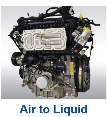
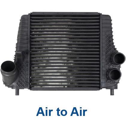
The heat of compression needs to be removed from the intake air stream for peak efficiency. Using an intercooler will remove that heat. There are two versions used as shown.
better low-end response over the single-scroll design, while still delivering high output power.
The variable-geometry turbocharger (VGT) design is also used to lessen the turbo lag effect. The VGT will control the amount of exhaust gases that flow onto the exhaust turbine. By doing this you have the best of both worlds; a large blade turbocharger that performs well at high RPMs and a small blade turbocharger that works well at low-mid RPMs (the most common driv ing range).
The supercharger is a positive displacement air pump that will deliver a fixed volume of air per supercharger revolution, increasing the pressure of the induction system. The supercharger boosts engine horsepower and torque by increasing the air mass being forced into the engine cylinders. The supercharger is directly driven by the engine, often by a drive belt and this di rect link to the engine creates an instantaneous power boost without any lag.
Supercharging is often used on large displacement engines because it will create significantly more power than a turbocharger. Superchargers used by the OEMs typically boost the induction pressure by 5 to 15 psi. Su perchargers deliver a smooth linear power boost from low to high engine RPMs. But this linear power boost does come at a cost, as the supercharger creates a para sitic drag on the engine, slightly lowering fuel economy (particularly in high-performance applications) and they are often noisier than a turbocharged engine.
There are three common supercharger designs be ing used today:
The Roots supercharger uses a set of triple-lobe 60-degree twisted helix rotors that will compress the incoming air to a positive pressure against the outside walls of the assembly as they rotate. This is the most popular but least efficient supercharger design.
The Twin-Screw supercharger (or Lysholm TwinScrew Supercharger, named after the inventor) uses a set of meshing, twisting conical shaped tapered ro tors, which will squeeze the air pockets between the rotors as they rotate. This type of supercharger is more efficient than the Roots type but is more expen sive to manufacture.
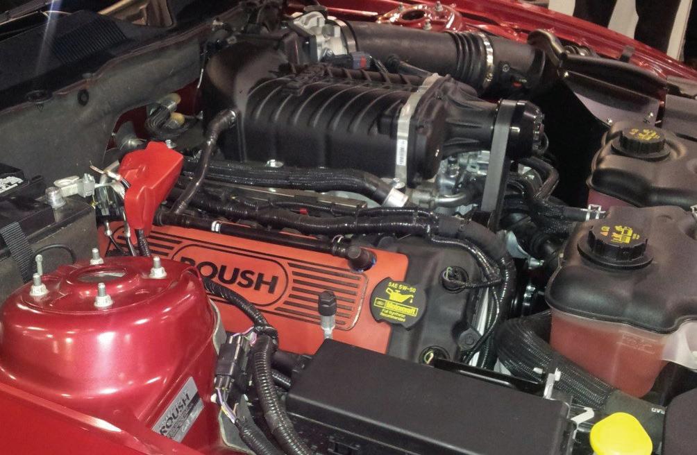
Aftermarket forced induction is popular as seen in this aftermarket supercharger and turbocharger installation.
The Centrifugal supercharger uses an engine driv en impeller spinning at 50-65,000 RPM to pressurize the intake air. This style of supercharger is the small est, lightest and most efficient, but most exotic type. It looks like a turbocharger and is used on the Koenigsegg super car. It works best at very high engine RPMs.
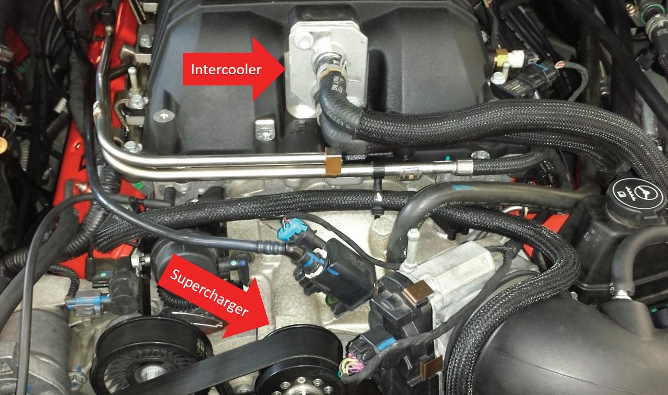
The intake manifold of the supercharger-equipped engine still favors the cast aluminum design, especially for the lower section because it often contains the in tegrated supercharger assembly and the intercooler. Typically, the upper cover is now plastic, but aluminum is often still used for strength and noise suppression.
Both the turbocharger and the supercharger are go ing to increase the temperature of the intake air stream because they are compressing it. For both of these forced induction systems to work at peak efficiency, the heat of that compression needs to be removed. Hot intake air is less dense and cannot supply the same amount of power as cooler air.
An intercooler is used to remove this heat and increase the density of the air before it enters the engine via the intake manifold.
There are two basic intercooler designs: air-to-air and air-to-water. These are often integrated into the intake manifold of the engine. Many of the air-to-water
intercooler systems use the engine’s cooling system to remove the heat from the compressed air, transferring it to the cooling system so that it can be removed by the radiator. Other air-to-water intercooler systems, like the 2021 Ford 5.2L SC Mustang, have their own dedi cated cooling system, coolant pump and radiator. The air-to-air intercooler design often associated with a turbocharged engine will route the hot compressed air to the grill area where the intercooler will be mounted shedding the heat to the atmosphere.
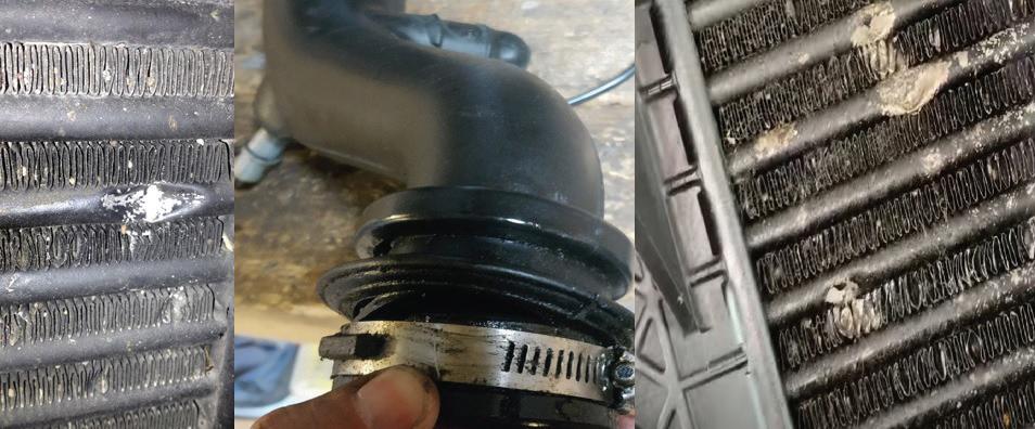
Neither the NA nor forced induction system have escaped issues. The early plastic intake manifolds were prone to cracking, breakage, EGR heat damage and cool ant corrosion. Rubber throttle body boots/snorkels de composed because of oil contamination or the constant flexing and engine vibrations causing induction leaks. Vacuum leaks are still a common issue on the NA induc tion system and will turn on warning lights and set diag nostic trouble codes. Turbocharged systems suffer from the loss of boost pressure, triggering warning lights, af fecting drivability, and often creating noise or whistling complaints caused by leaks from the induction system. Turbocharger issues are common, for assorted reasons... wastegate failures, control issues, ignoring service in tervals, and use of improper engine oil are all common causes of turbocharger failure. Supercharger gear whin ing and drive clutch noises are common. The forward mounted air-to-air intercoolers suffer road debris and corrosion issues that can cause leaks.
The induction system of today’s vehicles is a vital component in the overall engine management system. The trend is away from the NA engine for reasons of efficiency and power output and toward the forced in duction engine. The use of the current forced induction technology has increased engine power output while reducing the engine’s displacement size, all while still meeting the common goal of reducing exhaust emis sions and increasing fuel economy.
Jeff Taylor boasts a 30-plus-year career in the automotive industry as a fully licensed professional lead technician. Jeff works for the CARS Training Network Inc. in Oshawa, Ontario, Canada. He is also heavily involved in government focus groups, serves as an accomplished technical writer, and he has competed in international diagnostic competitions as well as providing his expertise as an automotive technical instructor for a major aftermarket parts retailer.
The automobile has gone through many changes over the years. While some are noticeable, like carburetors and fuel injection, brake pads, rotors, drums and shoes look similar to how they did 20 years ago but are really quite different.
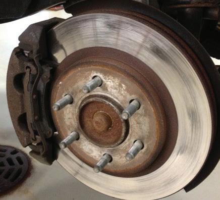
Semi-metallic and ceramic brake pads have advantages and drawbacks. Semi-metallic style pads are great for work trucks, performance vehicles and overloaded minivans. Ceramics are great for light duty trucks, everyday drivers and drivers that love clean wheels. How have friction materials changed the way technicians do brake jobs? It’s the way the friction stops the vehicle. Semi-metallic lining uses abrasion to stop and is very hard on rotors. The rotor is being worn down every time the pad touches the rotor, which leads to dust on the wheels.
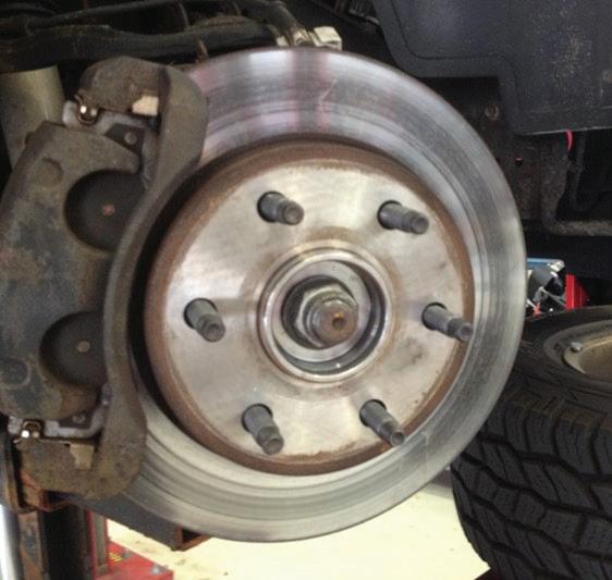
Ceramic brakes stop with adhesion. The brake pad leaves an ultra-thin layer of ceramic material on the rotor every time they make contact called material transfer (fig 1). The braking process consists of the ceramic pad rubbing against the ceramic transfer material on the rotor, causing an adhesion stop. This process does not wear down the rotor but increases the thickness of the rotor with every brake. It’s also the reason ceramic brakes keep the wheels cleaner. Since the rotors are not being worn down like semi-metallic pads, there is no rotor dust over the chrome wheels.
The biggest change when servicing brakes today is checking combined rotor/hub runout. With semimetallic wearing the rotor surface and ceramics adding material, make sure the rotors run true and don’t touch the pad unless the brakes are applied. The average allowable runout on today’s vehicles is .002”. The wheel turns about 800 times a mile, 1.6 million in 2,000 miles. If the installed rotor has .007” lateral runout, the pad will contact a portion of the rotor every revolution. With semi-metallic pads, the rotor is wearing thinner in one area.
(fig 1) (fig 2)

Ceramic pads are applying material in one spot (fig 2). As soon as the thickness variation exceeds .001, the driver may start to feel a pulsation in the brake pedal. This is the reason for “warped” rotors two-three months after the brake service. They are not really warped but have disc thickness variation (DTV). Take a couple minutes and clean the hub and check the runout when servicing brakes.
raybestos.com
Be Ready. Be Prepared.


With the Raybestos® Element3™ premium brake line, you are always ready and prepared, no matter the weather outside. With a demonstrated commitment to research, development and testing, technicians can install Raybestos products with confidence this winter. www.raybestos.com




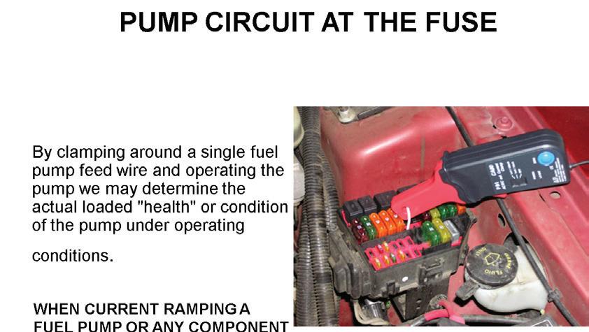
order to do a signal trace on a volt age waveform could be a challenge. In addition, back probing a connec tor or piercing a wire can disturb the circuit. If you remove a relay and jumper across the power side of the relay, or remove a fuse and jumper across the fuse in order to current ramp a fuel pump, the circuit has been disturbed. A non-intrusive test involves using the low inductive amp probe interfaced with the Digital Storage Oscilloscope (DSO) and mon itoring the current ramp values and the integrity of the amperage waveform when using the DSO.
Virtually every 12 volt output device that is con trolled by the PCM can be current ramped by using the low inductive current probe non intrusively by simply clamping around the voltage feed wire or the ground side control wire. Amperage probes are not polarity sensitive, meaning if the waveform indicates a negative polarity we would simply reverse the amp probe or use the invert function of the scope.
In our DSO diagnostics article in the October issue of Auto Service Professional we specifically covered the five cardinal rules for good lab scope usage. We are go ing to remind our readers again about these important five rules in Fig.1.
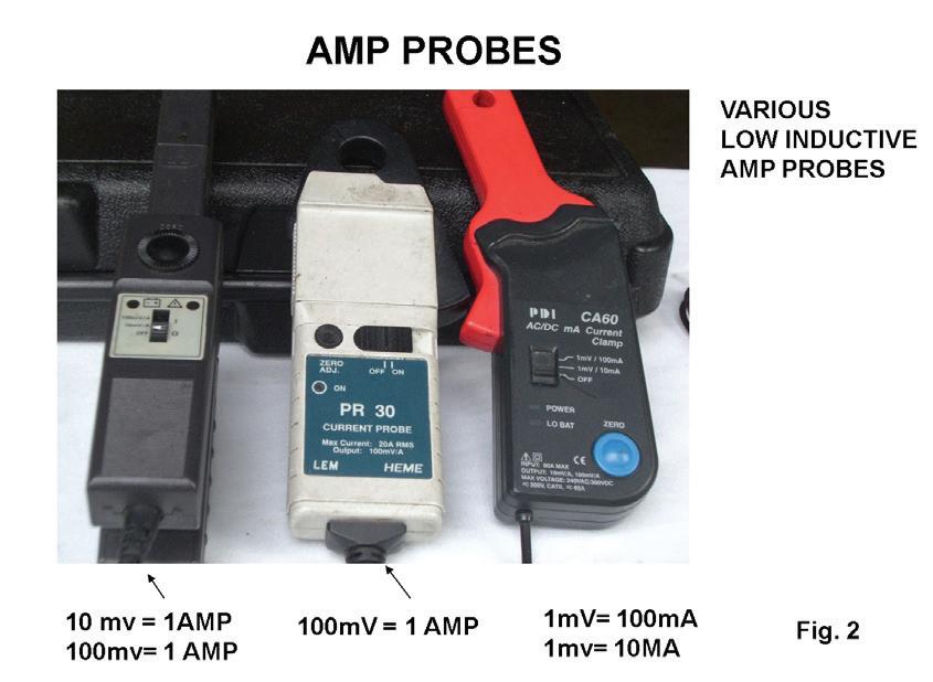
Low inductive amp probes can vary in their attenu ation settings, so first and foremost we must always be aware of these attenuation settings. Notice Fig. 2. The amp probe on the left has two attenuation settings. The first setting is for every 10 mV = 1 amp. This would
be the choice on a circuit that may draw as much as 40 amps. The second attenuation factor set represents ev ery 100mV = 1 amp. This is the most popular attenua tion setting and should be used on circuits that draw less than 20 amps which would include virtually every PCM output device.
The center amp probe has one setting: for every 100mV = 1 amp. This is my favorite setting. The amp probe on the right has two settings: one for every 1mV =100 mA and the second is for every 100 mV = 1 amp.
If you are current ramping a circuit that requires less than 20 amps, the 100mV = 1 amp setting would be preferred. On circuits where the amperage value can reach 40 amps, the 10mV = 1 amp would be preferred. The 100mV = 1 amp setting would be the first choice for
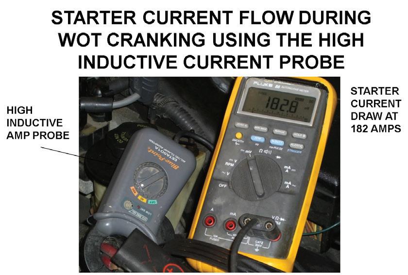
most automotive applications. Most low inductive amp probes should not be used on circuits where the amper age exceeds 40 amps. The high inductive amp probes are designed to diagnose amperage values that exceed 40 amps such as starting circuits. Note Fig. 3. The two attenuation factors are 40 amps that can be used for charging circuits or the 400 amp setting that is used for starter current draw.
Access to the secondary circuit on some modern engines is very difficult when checking for spark using a high energy spark tester. Using a low inductive amp probe clamped around the voltage feed wire to the coils somewhere in the harness can determine whether or not we get an ignition event.
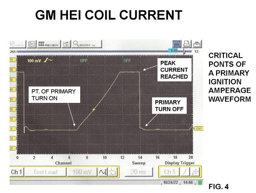
Let’s take a look at Fig. 4. The attenuation factor is
Fig. 2: The amp probe on the left has two attenuation settings The first setting is for every 10 mv=1 amp. The second represents every 100mv=1 amp.
Fig. 3: The high inductive amp probes are designed to diagnose amperage values that exceed 40 amp. The two attenuation factors are 40 amps that can be used for charging circuits or the 400 amp setting for starter current draw.
set for every 100 mV = 1 amp. This is the most popu lar attenuation setting and my favorite. Notice that the current ramps measure 6.5 amps.
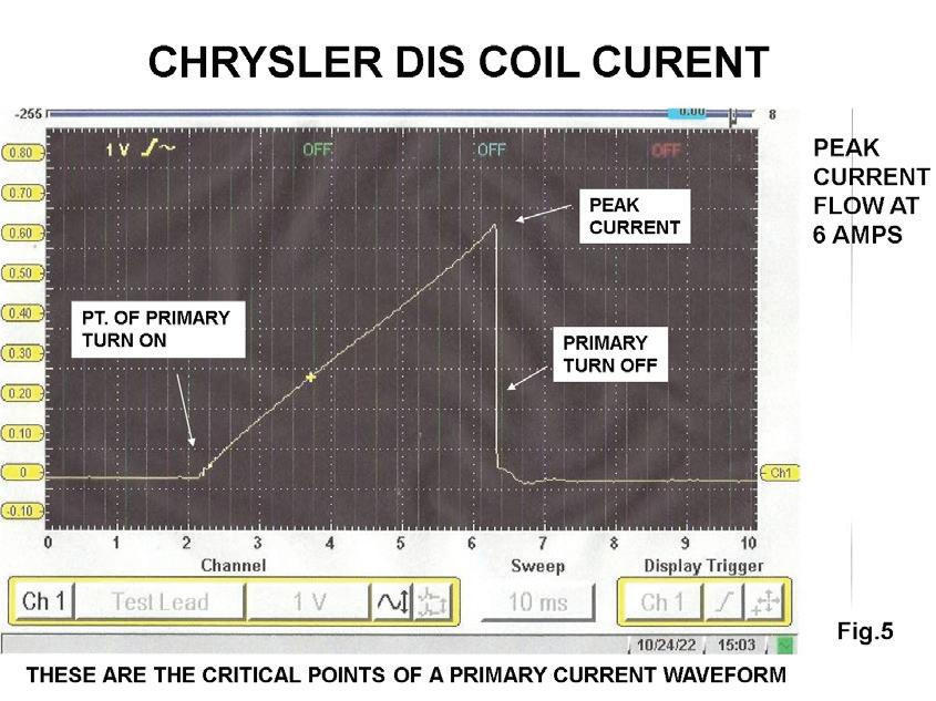
Just as important as the amperage values is the clean turn off point of the amperage waveform, representing a good transfer of energy from the primary side of the coil into the secondary side of the coil. We pointed out the critical points of a primary amperage waveform in Fig. 4. Many systems such as GM and Ford will clamp the current flow from the internal circuitry of the igni tion module or the primary drivers inside the PCM to about 6.5 amps. A primary amperage waveform from a Chrysler DIS system is indicated in Fig. 5.
The GM COP units can peak to nearly 10 amps on a cold startup. Note the amperage waveform in Fig. 6
Fig. 4: This is the most popular attenuation circuit and my favorite.
Fig. 5: Example of a primary amperage waveform from a Chrysler DIS system.
from a GM COP unit. The vertical setting is set at 200 millivolts equal 2 amp. You can see that the amperage value is about 10 amps. This provides a longer spark du ration period.
In our previous article we covered the importance of viewing the spark duration periods of a secondary or a primary ignition voltage waveform. A primary amper age waveform will not show us this important factor. Problems in the secondary circuit like fouled plugs, bad ignition modules, and poor coil saturation such as weak coils or bad module grounds and internal coil carbon tracking can be detected by monitoring the primary ignition amperage waveform. Let’s go ahead and show you some primary amperage waveforms from some problem vehicles.
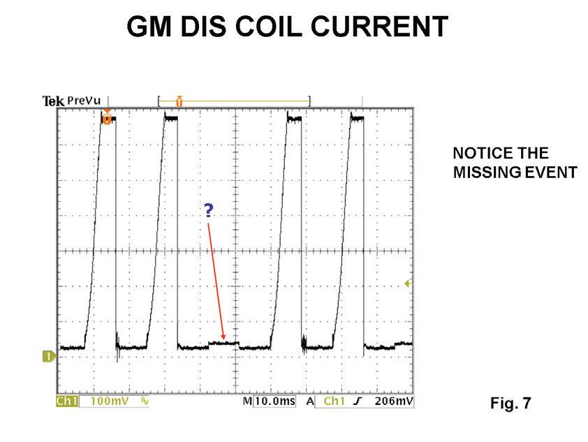
In Fig. 7, notice there is a missing primary event from this GM DIS system. A closer look shows a slight
Fig. 6: Amperage waveform from a GM COP unit.

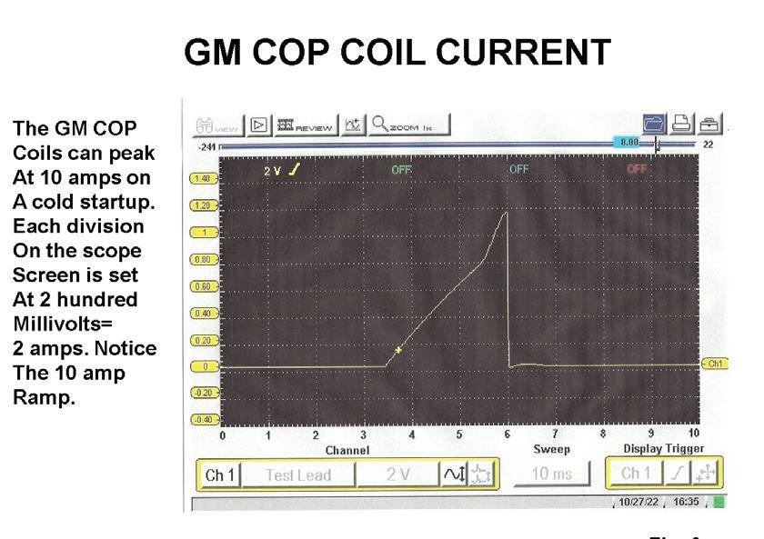
Fig. 7: Note the missing primary event from this GM DIS system. A closer look shows a slight stair step current ramp.
stair step current ramp. This slight ramp is the cur rent ramp to the base and emitter part of the transis tor that controls the primary current flow. The prob lem could be in the module or open primary windings inside the coil.
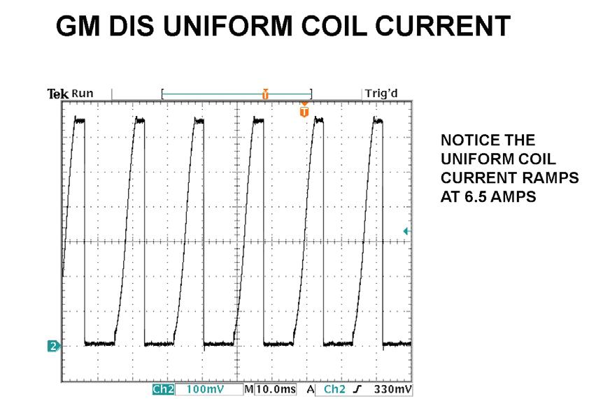
After the ohmmeter check of the primary and sec ondary windings of the coil checked OK, the module was replaced. Fig. 8 shows a good uniform coil current ramping with no signs of internal coil carbon tracking. Another example of where an amp probe could help in our diagnostics is indicated in Fig. 9.
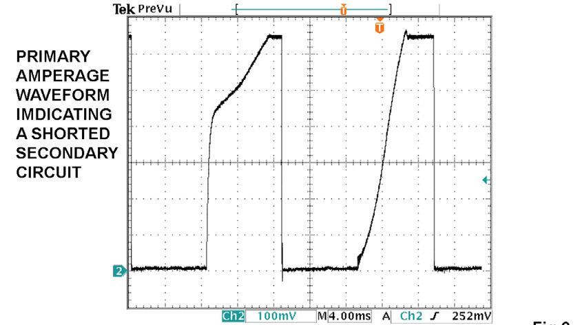
Notice the steep current ramping of the first pri mary event. This could be caused by a dead short in the secondary circuit or a totally fouled spark plug. This waveform was captured from an integrated di rect ignition system where using a spark tester would be very difficult. We simply clamped around the B+
Fig. 8: A good uniform coil current ramping with no signs of internal coil carbon tracking.
Fig. 9: Notice the steep current ramping of the first primary event. This could be caused by a dead short in the secondary circuit or a fouled spark plug.
Federated is honored to serve as a corporate partner of the U.S. Marine Corps Reserve Toys for Tots campaign. This holiday season, Federated and its members will be raising money and collecting toys at their stores nationwide that will be donated to Toys for Tots.
For more information about participating or donating, visit www.federatedautoparts.com/ ToysForTots.aspx.

wire outside of the valve cover. The second current ramp looks normal.
A Honda with a V-6 3.5L engine came in with a rough idle and a lack of power complaint along with a dead miss you could easily feel. A visual was performed and found nothing out of the ordinary. A scan tool was used to check for codes and found none. We clamped our cur rent probe around the B+ feed wire to the COP units and observed the waveform in Fig. 10.
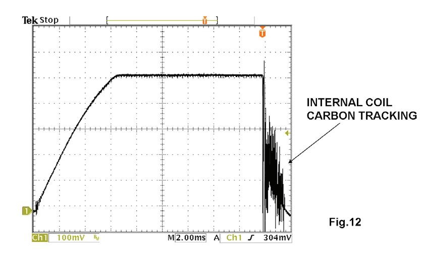
Notice the missing coil primary amperage event from the No. 3 coil. The No. 3 trigger signal from the PCM looks good. The No. 3 coil was replaced and scope checked again as in Fig. 11. Internal coil carbon tracking is one of the leading causes of coil failures and misfires. Note Fig. 12. Notice the indication of electrical activity
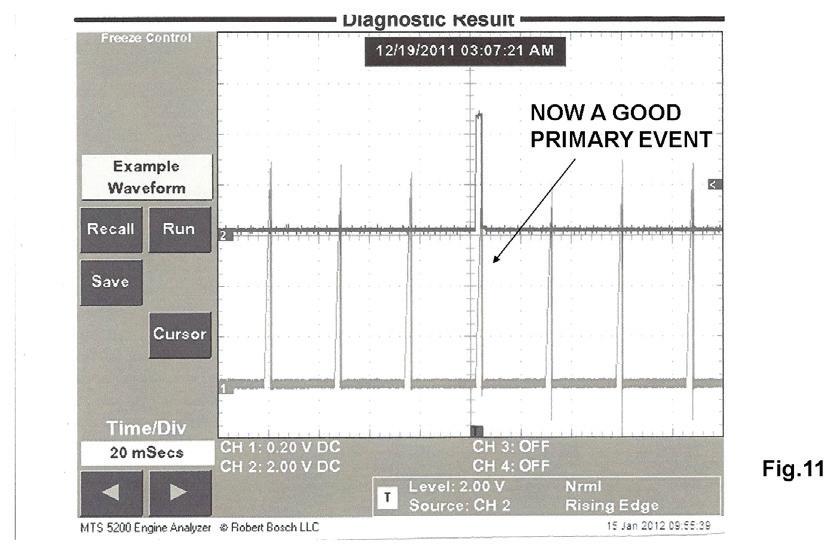
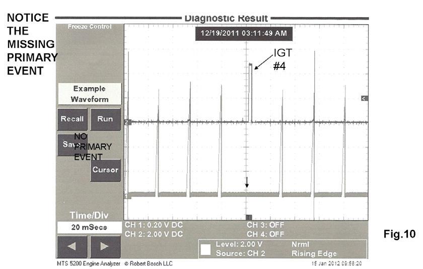

Fig. 10: Example of a Honda V6 3.5L with a rough idle and lack of power. After checking with a scan tool and finding no codes, we clamped a current probe around the B+ feed wire to the COP units and observed this waveform. Notice the missing coil primary amperage from the #3 coil.

after the point of primary turn off from a coil with inter nal carbon tracking.


Modern day ignition systems are of the divorced type, meaning there is no hard-wired circuitry between the primary windings of the coil and the secondary windings. The two windings are separated by an air gap inside the coil. When primary current flow is turned on by the module a positive magnetic field builds on the primary side of the coil. A negative magnetic field also begins to build in the secondary circuit. The opposing magnetic fields create a counter voltage effect between the two circuits.
In Fig. 13 we dual traced a primary coil current event along with a secondary event. The DSO setting for the current probe is set at 20mV per division and the DSO
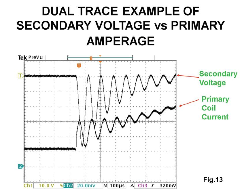
Fig. 11: On the same Honda 3.5L engine, the #3 coil was replaced and scope checked again.
Fig. 12: Notice the indication of electrical activity after the point of primary turn-off from a coil with internal carbon tracking.
Fig. 13: Here we dual traced a primary coil current event along with a secondary event. The DSO setting for the current probe is set at 20mV per division and secondary voltage trace is set at 10 volts per division.
setting for the secondary voltage trace is set at 10 volts per division. This gives us a magnifying effect of the point of primary turn on. If the secondary is shorted including a totally fouled plug you will not see these oscillations. If you refer back to Fig. 9 you will see the missing oscillations.
Checking for fuel pressure has become more dif ficult on many systems because many manufacturers have done away with the convenient fuel pressure test point. Current ramping the fuel pump with an amp probe can easily verify whether or not we have fuel pressure, as shown in Fig. 14.
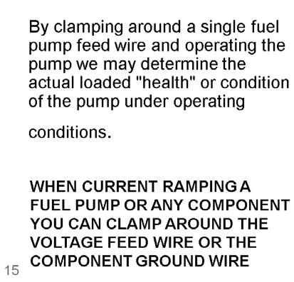
On conventional port fuel injection systems, 4 to 6 amps is very close to 40 PSI. A good formula is for every 1 amp = 10 PSI. See Fig. 15.

Fig. 14: On conventional port fuel injection systems, 4 to 6 amps is very close to 40 psi. A good formula is for every 1 amp = 10 psi. In addition to amperage value, amperage waveform oscillations can help to detect fuel pump electrical problems.
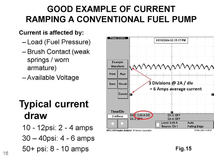
Fig. 15: Example of an open commuter bar causing an intermittent stall/no-start.
In addition to the amperage value, the amperage waveform oscillations can help us detect electrical problems of the fuel pump such as open commuter bars or shorted windings. In addition, poor fuel pump grounds and a weak voltage source to the fuel pump will diminish the current flow value. Let’s look at some fuel pump problems using the low inductive amp probe interfaced with a DSO.
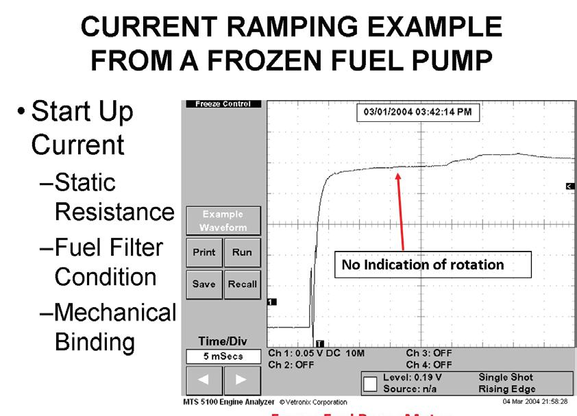
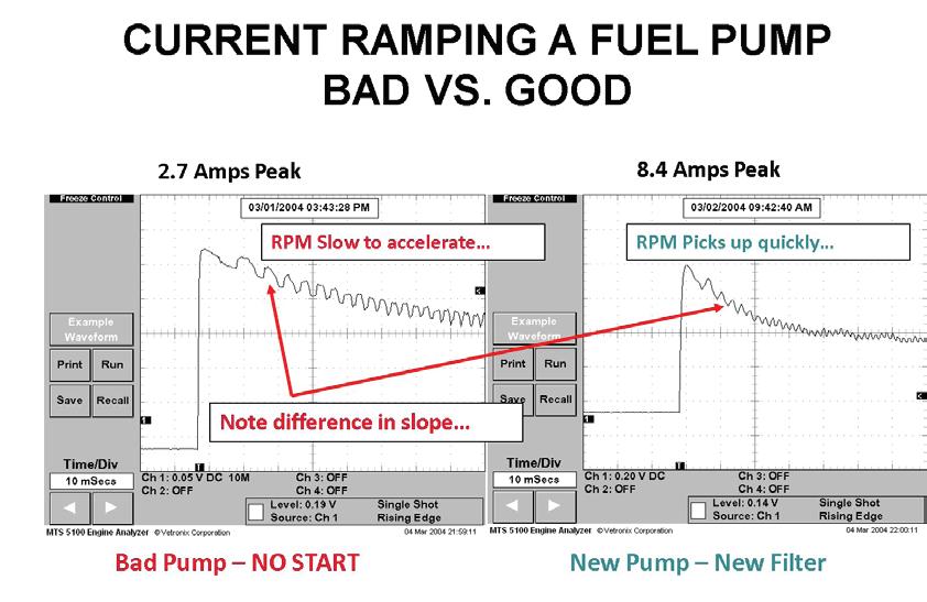
Fig. 16 indicates an open commuter bar causing an intermittent stall and no start. Fig. 17 is from a vehicle with a no start. Notice there are no oscillations due to a frozen pump. This is a car when you banged on the fuel tank you could hear the pump run. On another vehicle in Fig. 18 the waveform on the left from the old pump shows a weak initial current surge of only
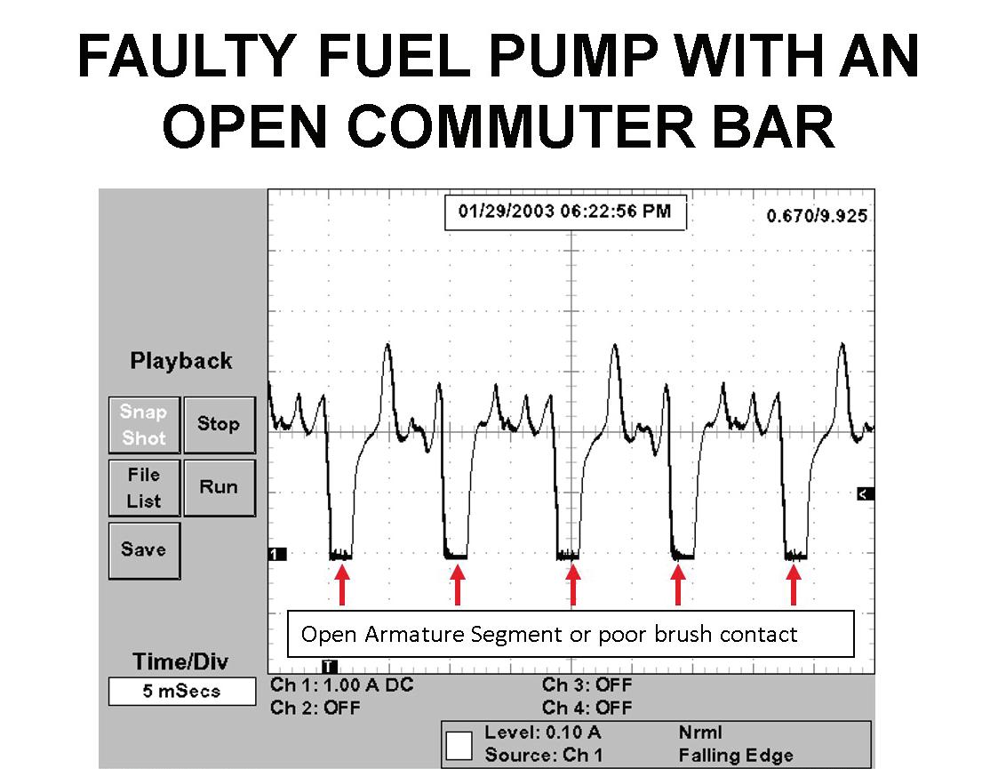
Fig. 16: Example of a vehicle with a no-start issue. Notice that there are no oscillations due to a frozen pump.
Fig. 17: In this example, the waveform on the left from the old pump shows a weak initial current surge of only 2.7 amps. On the right is the new pump, showing initial current surge of 8.4 amps.
2.7 amps. At 10 milliseconds per division, it took 70 milliseconds for the pump to come fully on line. The waveform on the right is from the new pump. Notice the initial current surge is 8.4 amps and the fuel pump is fully on line in 70 milliseconds.
Notice Fig. 19 from a Ford Ranger with a complaint of long cranking times after an overnight cold soak. A fuel pressure gauge was installed and indicated 40 PSI during KOEO and during cranking with a normal startup with the engine fully warmed up.
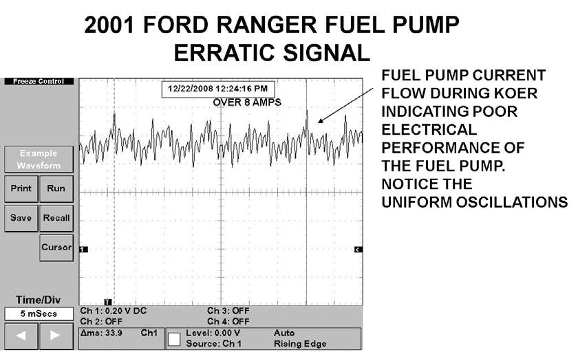
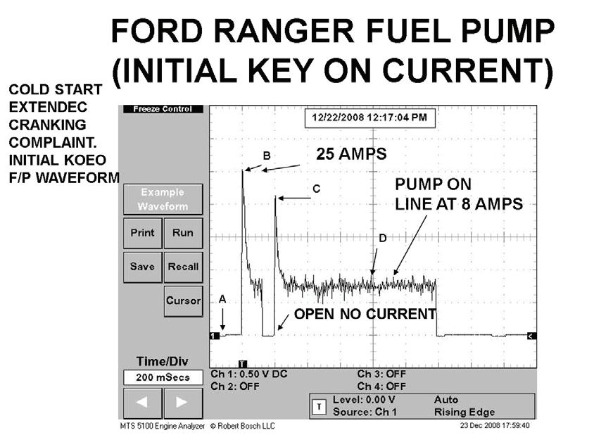
We know that the injector on time during a cold startup will reach double digit injector on times which required good fuel pressure and volume from the fuel pump. We clamped a low inductive current probe to the fuel pump feed wire at the inertia switch. In Fig. 19
Fig. 18: After clamping a low inductive current probe to the fuel pump feed wire at the inertia switch, the initial current surge hit 25 amps and then dropped to 22 amps followed by a brief open. Afterwards, the pump was on line at 7 amps.
Fig. 19: Waveform with the engine running. The waveform looks very erratic and a new pump and filter solved the problem.
the initial current surge hit 25 amps then dropped to 22 amps followed by a brief open. After that the pump is on line at 7 amps. With the engine now running let’s look at the waveform in Fig. 20.
This is an eight-segment armature pump. The waveform looks very erratic and a new pump and fuel filter solved the problem. Analyzing the cur rent waveform oscillations from conventional fuel pumps is an important diagnostic strategy.
On modern day vehicles a fuel pump control module duty cycle controls the fuel pump instead of a constant battery supply voltage found on the conventional systems.
The Ford fuel pump control module bangs the fuel pump with battery voltage 6,000 times a sec
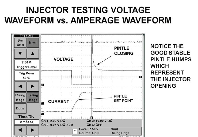
Fig. 20: Injector testing is easy using the low inductive current probe. Clamp around the voltage feed wire or the switching side of the circuit. Here is a dual trace example of injector tracing with the voltage trace at the top and the current ramping waveform at the bottom.
Fig. 21: Example of a problem vehicle with a P0305 misfire code. Current ramping the #6 injector shows three unstable pintle humps, known as pintle bounce.
ond and increases the duty cycle on time as engine load is increased.
The GM fuel pump control module bangs the fuel pump with battery voltage at 25,000 times a second.
As in the Ford systems, the duty cycle on time will be increased as engine load increases. Because of this the signature waveforms do not resemble that of the conventional fuel pump. However, the amperage value is of prime importance. Typically, during idle conditions these pumps draw about 4 amps. During a power brake condition, you will see an increase in amperage demand as the duty cycle signal from the PCM is increased.
Injector testing becomes very easy with the low inductive current probe. We simply clamp around
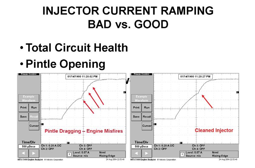
the voltage feed wire or the switching side of the cir cuit. Fig. 21 shows a dual trace example of injector tracing with the voltage trace at the top and the cur rent ramping waveform at the bottom.
If you look closely you will see a slight variation of the voltage trace and a slight variation of the cur rent waveform. These represent the pintle hump as the mass of the pintle breaks across the magnetic field. Fig. 22 is from a problem vehicle with a PO306 misfire code. Current ramping the No. 6 injector
Fig. 24: Example of the PCM drive signal for a GDI high pressure pump. The red trace is the voltage drive signal. Notice that the inductive lick measures 45 volts, verifying good electrical integrity of the solenoid.
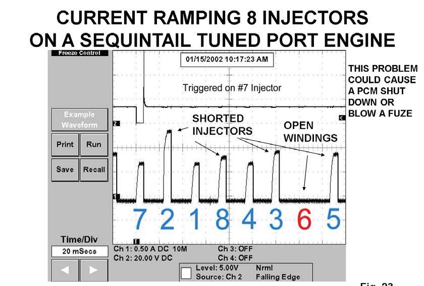
Fig. 22: Example of a V8 tuned port engine, current ramping all eight injectors by clamping around the pink feed wire. These 12ohm injectors should pull about .7 amps. Notice that the #2, 8 and 3 injectors are shorted and the #6 indicates an open winding.
Fig. 23: When checking GDI injector signals, a 2-channel trace must be used.
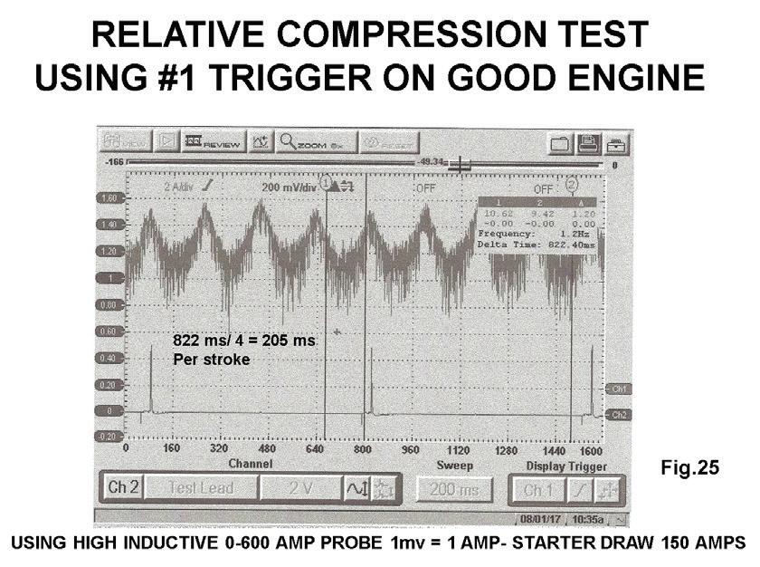
Fig. 25: A high inductive current probe can be clamped around either battery cable to aid in checking engine mechanical integrity on high-mileage engines, conducting a wide-openthrottle 10-second test. Starter current flow will increase as each piston reaches TDC on the compression stroke. Notice the uniform amperage value of 150 amps from a good engine.
shows three unstable pintle humps. This is known as pintle bounce. We informed the car owner we could try an injector cleaning process and the waveform on the right indicates a single stable pintle hump with no misfires.
Fig. 23 is from a V-8 tuned port engine where cur rent ramped all eight injectors by clamping around the pink feed wire. These 12 ohm injectors should pull about 0.7 amps.
Notice that the No. 2 injector, the No. 3 injector and the No. 8 injector are electrically shorted. The No. 6 injector indicates an open winding. We trig gered from the No. 7 injector.
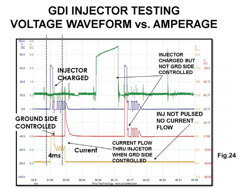
Testing GDI injector drive signals has been more difficult. Using Noid lights and multimeters will not work. When signal tracing a GDI injector drive sig nal for a voltage trace you must use a two-channel trace, with channel 1 on one wire with channel 2 on the other injector wire. The PCM will charge capaci tors with 65 volts for the injector circuits.
In Fig. 24 the first blue waveform on channel 1 indicates a 65-volt charge. The bottom red waveform indicates that the PCM supplied the ground and the injector is pulsed. Notice the amperage yellow wave form indicating a 7 amp draw since the PCM sup plied the ground.
It is clear to see that using a current probe on these systems is much easier than doing a voltage trace. Moving to the right, notice the top blue trace
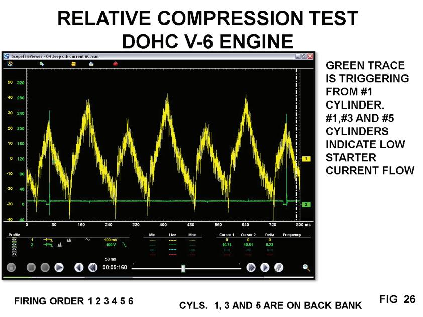
Fig. 26: Example of a high-mileage engine with a lack of power complaint. Notice the uneven starter current is low on the bank 1 cylinders, which could be caused by a retarded timing problem on that bank, or possibly a catalytic converter restriction for bank 1.
indicates a 65-volt charge as well as the bottom red trace. The bottom blue trace is not pulled to ground and the injector is not pulsed. The green trace is the RPM IC signal from the No. 1 coil control. Notice the amperage yellow trace does not indicate that the injector was ground side controlled.
Mechanical integrity issues on high mileage en gines have always been a concern as to what may be causing a misfire code, a misfire symptom or a lack of power symptom. A high inductive current probe clamped around either battery cable and then to conduct a WOT 10 second cranking test. The starter current flow will increase as each piston reaches TDC on the compression stroke. Note Fig. 25. Notice the uniform amperage value of 150 amps from a good high mileage engine. The low pass filter or noise re duction function of the scope was not turned on.
Fig. 26 is from a high mileage engine with a lack of power complaint. Notice the uneven starter cur rent low on the cylinders from bank 1. This is caused by a retarded timing problem on bank 1. You must also entertain the possibility of a restricted convert er on bank 1.
Current ramping is an easy art to learn and re turns many good returns. In our next article we hope to cover the diagnostic value of the pressure transducer and the vacuum transducer interfaced with the DSO.
Thanks for your commitment to this very re silient industry. The industry is better because of your commitment.
Bill Fulton is the author of Mitchell 1’s Advanced Engine Performance Diagnostics and Advanced Engine Diagnostics manuals. He is also the author of several lab scope and drivability manuals such as Ford, Toyota, GM and Chrysler OBD-I and OBD-II systems, fuel system testing, and many other training manuals in addition to his own 101 Lab Scope Testing Tips. He is a certified Master Technician with more than 30 years of training and R&D experience. He was rated in the top three nationally on Motor Service magazine’s Top Technical Trainer Award and has instructed for Mitchell 1, Precision Tune, OTC, O’Reilly Auto Parts, BWD, JD Byrider, Snap-on Vetronix and Standard Ignition programs. You may have also seen Fulton in many Lightning Bolt Training videos and DVDs and read his articles in many auto service magazines. He owns and operates Ohio Automotive Technology, which is an automotive repair and research development center and where the images for this article were produced.

AFTER TEACHING HYBRIDS FOR TEN years at ACDC (my third automo tive business), I bought a new 2011 Chevy Volt to add to our existing fleet of the best-selling hybrids from Honda, Toyota and Ford. This was an exciting time as this had a plug to charge the high voltage battery and it was no longer nickel metal hydride (NiMH). ACDC now had more to learn and pass onto the industry, so we got to work!
On a good day, the Volt has a range of about 37 miles on battery power only (it has a back-up gas engine). If I drive back roads at 35 mph maybe I can squeeze out 45 miles. During the winter in central Massachusetts, the range is less than 20 miles on electric power only.
A couple years later ACDC bought a used 2011 Leaf to advance our knowledge. The range on the Leaf was 85 miles in the summer, but only 50 miles in the winter.
ACDC leased a Chevy Bolt EV in 2017 and this EV had a range of 230 miles in the summer, but again the winters took it down to 160 miles.
What did they all have in common? The cabin heat was created by the high voltage pack heating anti freeze for the heater core. How old school.
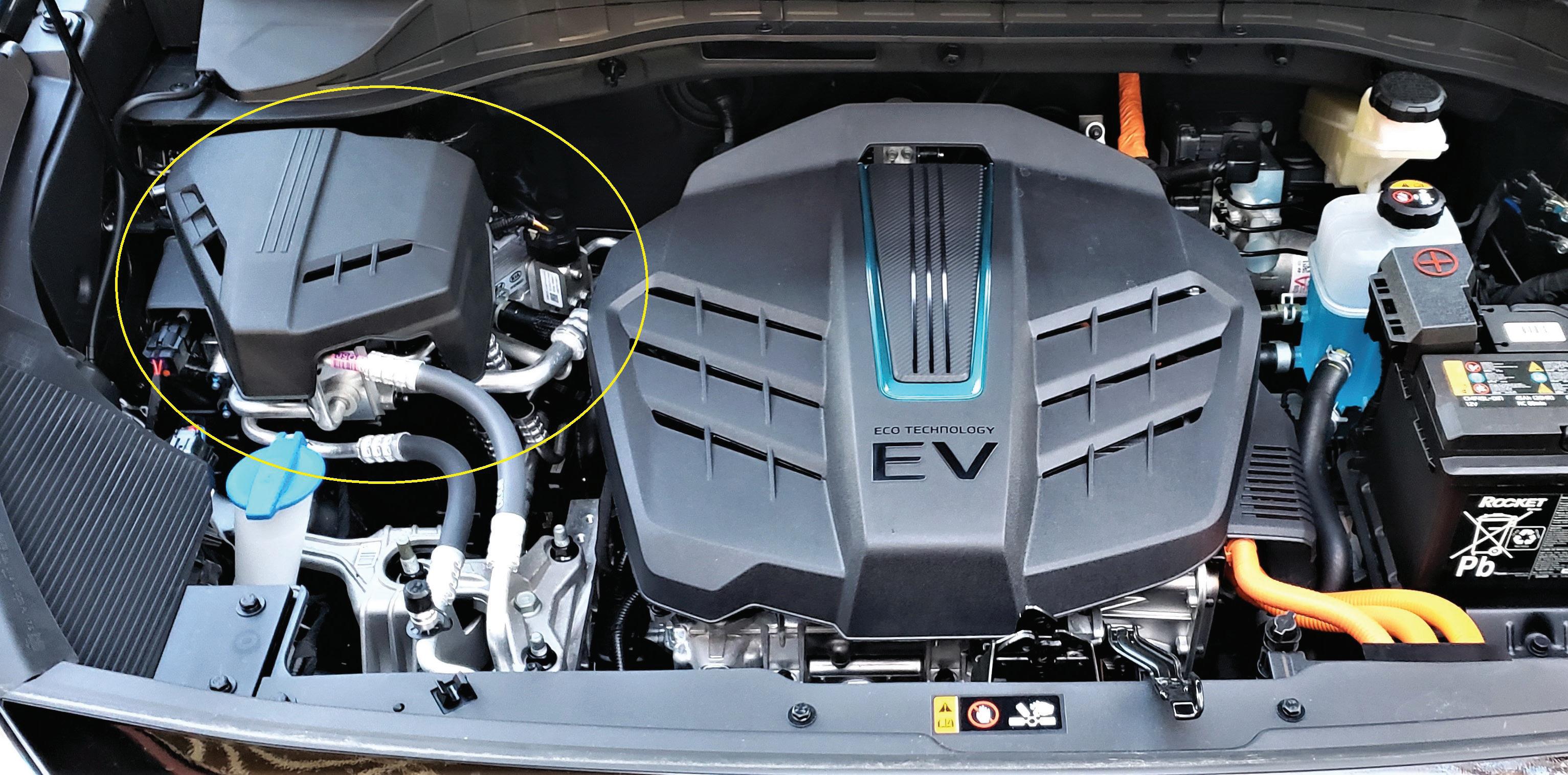
Once the lease was up in 2020, ACDC was in the market to buy an EV for training and longer distance driving in cold weather. The answer to that was a 2019 Kia Niro EV. It had two components that we

lacked at our school: a DC faster charger known as CCS (Combined Charging System) and a heat pump.
Once affordable modern electric cars were offered worldwide in 2010, the heating of the cabin became a customer concern in cold weather. To provide cabin heat, a small container of coolant was heated using the high voltage (HV) battery for power, and that hot coolant was pushed into the heater core with a 12-volt motorized pump. The 2011 Nissan Leaf used a German made coolant HV heater, but it decreased the driving range. That old-fashioned technology (still in use) lasted only two model years before Nis san, in model year (M/Y) 2013, came out with a heat
pump. That reduced the load on the battery from ap proximately 6 kW to 2 kW, for the same amount of heat. This allowed the EV to go farther on a charge while keeping the occupants comfortable. To stay warm is a human desire, but in the beginning many early EV adopters used the heated seats and heat ed steering wheel, while wearing a jacket, hat and gloves, to stay warm with the heat off. That was not the solution most drivers would put up with.
How does a heat pump work? In simple terms, the condenser and evaporator change places by adding another expansion valve before the condenser. Then more tubing was added to bypass each expansion valve and the computer, depending on a request for heat or A/C, used one expansion valve or the other. In this way the heat is then produced in the cabin as you try to cool the air outside the vehicle. Heat pumps have been used in buildings since the 1940s, but the concept goes back to the mid-1850s.
When Nissan installed their version of a heat pump it was not used on the base model, the Leaf “S”, for the first six months of production, but by mid-year, all Leafs were using heat pumps. In M/Y 2015 the new Kia Soul EV added a “tweak” to its heat pump to make it more efficient. Toyota (Denso) then improved it again in the M/Y 2017 Prius Prime that allowed the heat pump to work at lower ambient temperatures. The Kia Niro EV, in M/Y 2019, added two more valves that kept the technology advanc ing to use less battery energy to warm the cabin and finally in 2021 the Tesla Model Y came out with the “Octovalve,” Tesla’s first heat pump.
If you have been keeping track, since 2013, ev ery two years the heat pump has been redesigned and with that has come improvements. Why all these changes? Consumers wanted more range in cold weather.
We will examine the ACDC generic heat pump (see illustration on page 42) we use in our classroom to help repair technicians understand the concept. The system has what looks like two evaporators. The traditional one is (11) and the second one is used for heating the cabin (2). The condenser (5) has two jobs as we will explain. The compressor (1) is a typical high voltage scroll type and uses an accumulator (9). The accumulator prevents any liquid from en tering the compressor. Two 12-volt solenoid three-
way valves (3 and 6) are fitted before each expansion valve (4 and 10) with a bypass line to direct the re frigerant either to the expansion valve or around it. The “three-way valves,” as they are referred to by the OEMs, have only two directions. The switching of the valves will allow the refrigerant to keep go ing straight through the same pipe, or be redirected to another pipe. It has only two choices and only one expansion valve is open at any one time. There are also sub-systems that are needed to support a heat pump in damp and very cold weather, or a subsystem to make it perform better. Expect more im provements in the future, and if the past can predict the future, it will be in 2023.
If there was ever a poor choice of words, calling something that gets hot a “chiller” would be it (8). It cools the power electronics (PE) (7) but its purpose in the HVAC system is to warm the refrigerant on its way back to the compressor. That makes it easier for the HV compressor to do its job. Less effort equals less energy from the HV battery and more range. A lot more range? No, but every little bit helps. The PE coolant had not been used on the Nissan Leaf
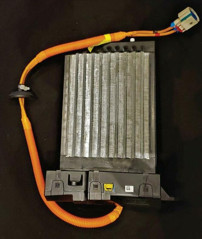
This high voltage grid heater takes over when the outside condenser freezes in damp, cold weather.
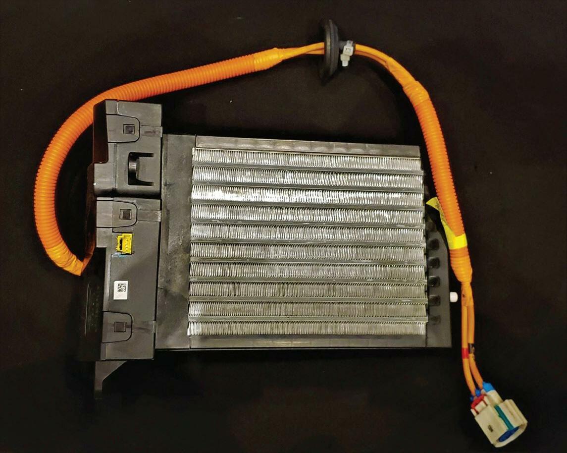
before, so now we are recycling energy (a Kia idea) we otherwise would lose as waste heat. Clever, those engineers. Reduce, Reuse and Recycle can be applied to transportation these days. Using wasted energy is smart. Wasting energy is not.
When the heat pump is on and the outside climate is wet and above freezing (33F to 45F or 1C to 7C), the outside of the condenser (5) may freeze as the air mov ing through the condenser lowers the air pressure and the temperature drops. If the condenser has iced up, the heat pump system stops working. What do we do? The HVAC computer will turn the A/C back on as this
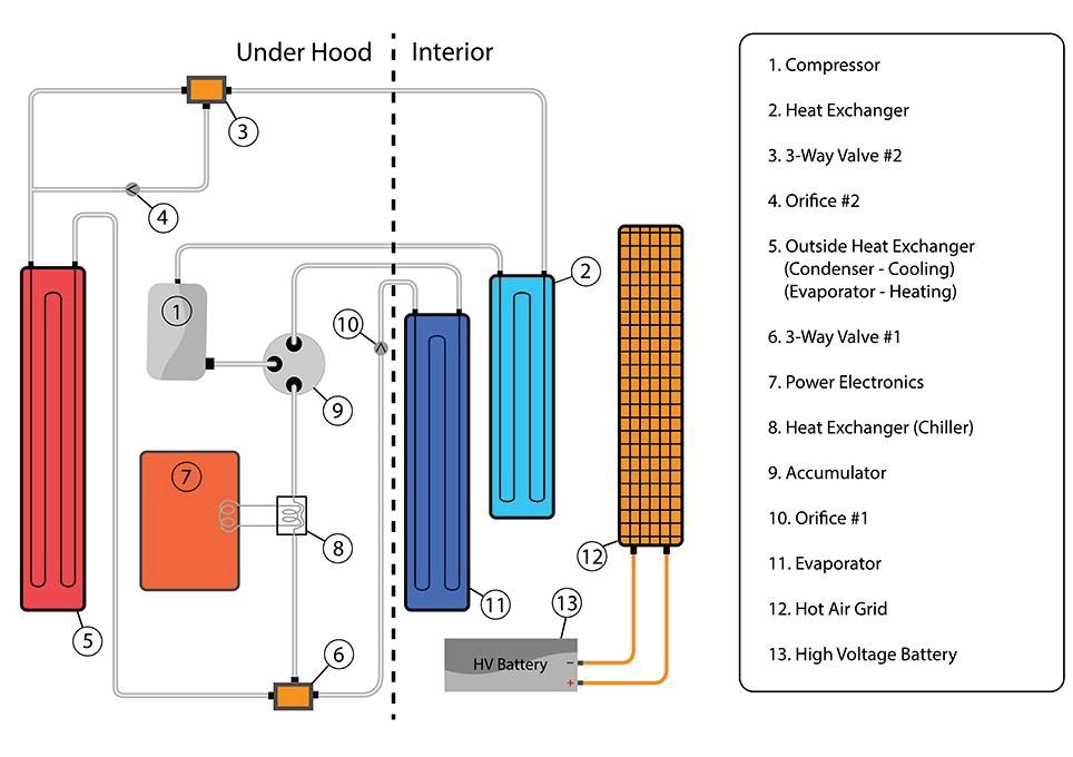
will now melt the ice when the condenser gets hot. Air flaps in the evaporator will move the “cold air” from the A/C outside as the HV air grid heater (12) is turned on to heat the cabin. At this point the main battery pack (13) will be asked to provide more energy than when the heat pump was the sole provider of cabin heat. As the outside (ambient) temperature drops be low freezing and/or the air dries out, the front con denser will stop icing up. This is all done without the driver knowing what is going on.
My company’s job is to provide training and tech support to the world’s independent EV technicians that will be asked to fix and maintain the systems as they age. This makes for an interesting job.
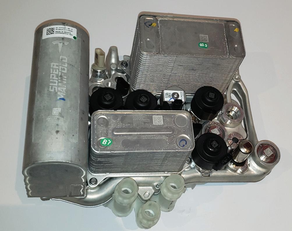
Tesla was late to the game with its Octovalve.


Craig Van Batenburg is the lead trainer and CEO of ACDC, a hybrid and plug-in technician training company based in Worcester, Mass. ACDC started hybrid training in early 2000. ACDC owns a fleet of 16 EMVs, from the most popular models to current EVs. Recently, ACDC has expanded to 5,000 square feet and added a battery lab. Class info is available at www.FIXEV. com or call 508 826 4546. Contact Craig at Craig@fixhybrid.com.
fuel tank is filled with “bad” fuel?
Well, it varies depending on how bad the fuel is and if the engine is gasoline- or diesel-powered. Fixes can range from cleaning the system with a fuel additive (isopropyl alcohol), flushing the system and refilling with “good” fuel, to needing to repair damage to the fuel system and/or engine.
Issues resulting from bad fuel can range from difficulty in engine starting, sputtering/pinging sounds while idling or driving, stalling, notable re duced fuel mileage, acceleration trouble, or errant vehicle speed changes while driving. The cause may be water in the fuel, “old” gas or dirt particles in the fuel. If you’re lucky, the fix might simply in volve replacing the fuel filter. One step worse, you may be replacing the fuel pump.
Water contamination likely leads the list with regard to fuel contamination. While issues have been previously reported on the East Coast in par ticular (from New Jersey to Florida, for example), the issue can present anywhere. Water contami nation is nasty. It can cause an array of problems aside from drivability issues, including fouling the fuel filter, damaging the fuel pump, or filter and fuel system issues caused by rust-laden, in-ground gas station tanks, fuel injector problems, etc. Old fuel (remember that gasoline has a shelf life) can cause sticky deposits that can easily create clog ging issues in injectors. Water-laden diesel fuel can create herculean problems in high-pressure injection pumps and a diesel engine’s oh-so-ex pensive injectors. On GDI engines (gasoline direct injection), just as in diesel applications, fuel pres sures are on the high side, in the thousands of ppm (parts per million). Any interruption of fuel pres
sure as a result of fuel contamination can result in the potential of ultra-expensive repairs. Water in fuel, which accumulates in the tank, results in rust buildup, and in warm/humid environments, micro bial (algae) growth.

In some cases, a contaminated fuel issue may easily be mis-diagnosed as a management system concern such as a bad fuel pump, a failed MAF sen sor or a lean condition DTC, when the cause may be the result of water in the fuel, E85 in a non-E85 compatible system, diesel fuel in gasoline, gasoline in a diesel, dirt or algae contamination, etc.
Some (perhaps many) consumers are unaware of the difference between gasoline and E85 (85% etha nol and 15% gas). This fuel, designed for use only in “flex fuel” vehicles, is not compatible with the fuel systems in vehicles that are not designed for E85 use. Adding E85 into an incompatible fuel system can
Gasoline engine injector O-rings depend on fuel for maintaining seal viability. Running E85 through non-flex-fuel designed injectors will degrade all soft materials.
corrode aluminum surfaces and destroy fuel system O-rings, seals, gaskets, fuel pumps (due to reduced lubrication), paper filters, injectors and hoses. E85 is also hygroscopic, which means that, similar to gly col brake fluid, it absorbs moisture from the atmo sphere. Some ill-informed drivers may choose to add E85 simply because it’s a bit less expensive, or they assume that they’re being “environmentally friend ly” since they’re using a “bio” fuel. Such decisions will eventually lead to expensive engine repairs.
Regardless of the type of gasoline fuel system (carbureted, port injection, TBI injection or direct injection), and especially if the vehicle is operated in warm and humid conditions, advise your customers to avoid parking their vehicles overnight with a low fuel level in the tank. The greater the surface area of the fuel tank walls that are exposed to air, the greater the chance of condensation forming and water sink ing to the bottom of the tank. While in the real world this may be an impractical expectation, topping off the tank as frequently as possible reduces condensa tion issues. In other words, suggest that customers keep their tanks full whenever possible.
GDI injectors run at extremely high pressures, including this Piezio injector from Bosch. Contamination such as dirt/grit/algae can not only affect injector performance but can damage the injectors. (courtesy Bosch)
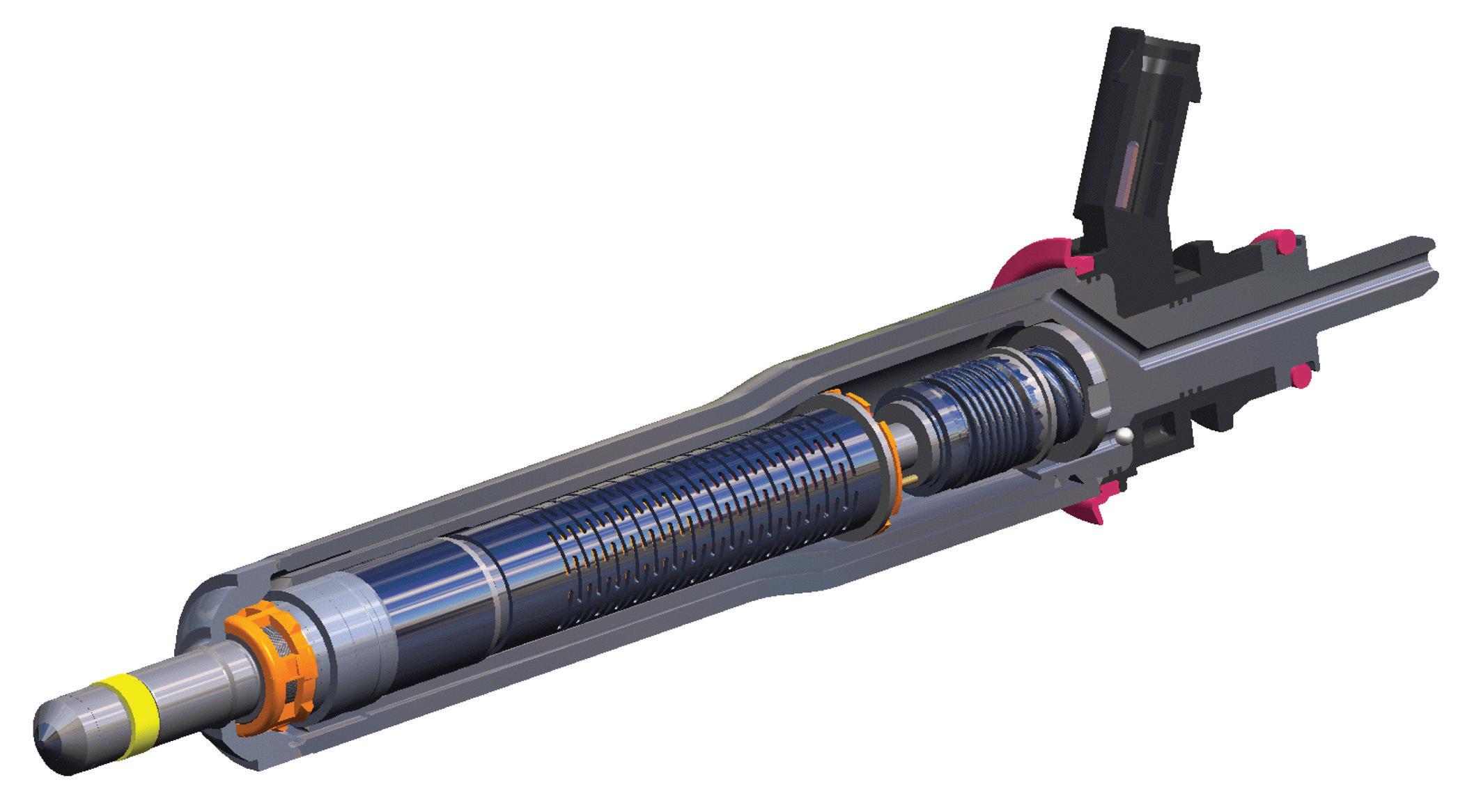
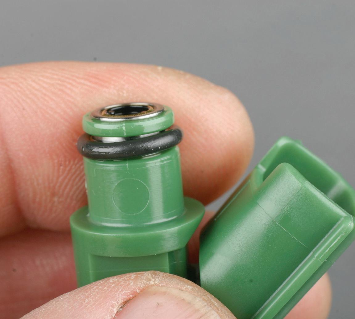
Speaking of diesel engines in particular, water con tamination can wreak absolute havoc on expensive fuel system and engine components. Diesel fuel can contain two levels of water concentration — water in solution or “free” water. Diesel fuel can contain low ppm levels of water that may be dissolved in the fuel (water in solution). This can be the result of condensation in the tank and fuel temperature. Water that is not dissolved in the fuel (free wa ter) accumulates in the bottom of the tank. If the fuel tank is made of steel, this can result in rust buildup and rust particles trying to pass through the system. Aside from naturally occurring in-tank condensation, the most common cause of water in diesel fuel is poorly maintained storage tanks from which the fuel is dispensed. Excessive water in die sel fuel can result in injector wear (in severe cases this can result in fuel injector tips exploding), sud den cooling of the engine that can cause intermit tent thermal shocks which can damage the engine, and in cold temperatures, gelling of the fuel which makes it difficult for the fuel to flow through the system and ignite under cylinder pressure. While port injection on a gasoline engine may be in the 40-60 psi range and a GDI injection system may
Diesel fuel injectors can be very expensive to replace. Rebuilding is the preferred cost-saving approach, but depending on damage, it’s not always an option.
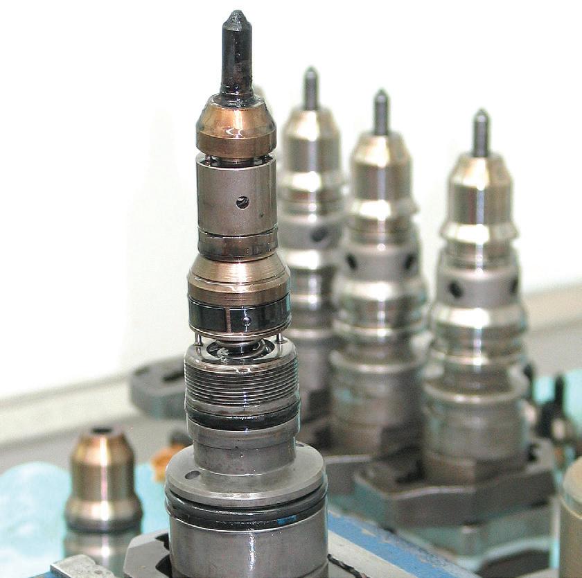
see in the range of 2,000 psi (high pressure needed to overcome combustion chamber pressure), a die sel injector may see anywhere from 3,000 upwards of a mind-boggling 30,000 psi. Given this level of pressure, it’s not difficult to understand how a clogged injector could literally explode under the wrong circumstances.
While low part-per-million levels of water usually don’t pose a problem, free water can easily cause en gine damage, filter pulling, loss of engine power and irreversible corrosion of fuel system components.
Tip: as noted earlier with regard to gasoline engines, it’s a good idea to top off the tank at the end of the day. This helps in getting rid of the hu mid/warm air in the tank, reducing/preventing condensation buildup. Excess water being pushed through a diesel engine’s fuel system reduces the lubrication needed for pumps and injectors that is normally provided by the diesel fuel.
Fuel additives are available specifically designed to clean up microbes and sludge. (courtesy Power Service)
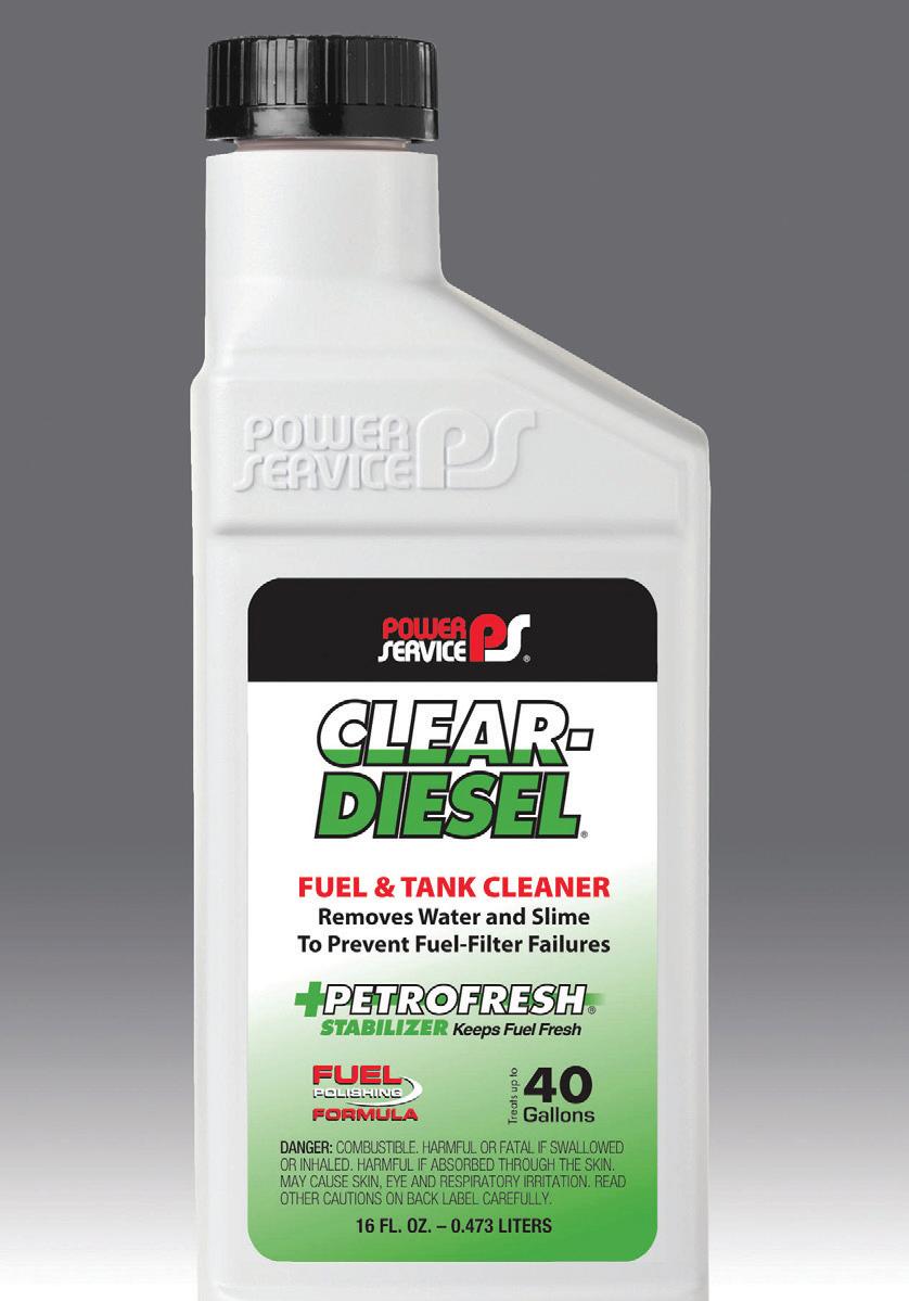
kee vehicles equipped with electric power steering (EPS). During EPS module electrical diagnosis and veri cation, DO NOT disconnect the gray EPS torque sensor connector on the EPS module. If the torque sensor connector is disconnected, the following issues can take place:
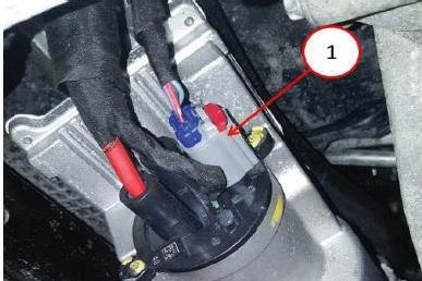
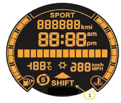
This bulletin applies to 2013 Fiat 500 vehicles equipped with a 1.4L engine, manual transmission and electronic vehicle information center (EVIC). The customer may notice when trying to select the gear shift indicator (Gear Shift Up) in personal setting, the shift indicator does not display in the EVIC. A re ash may be needed. Using a scan tool with the appropriate diagnostic procedures available in TechCONNECT, verify that no DTCs are set (if DTCs are present, record and repair as needed before proceeding). Update the software in the instrument cluster. The wiTECH software level must be at release 14.02 or higher.
• If one or two ignition cycles occur while the torque sensor harness is disconnected, DTC C2217-00 will be active in the EPS module. This code can be cleared. If three or more ignition cycles occur while disconnected, DTC C15DB-00 will be active. This code cannot be cleared, and the EPS gear will need to be replaced.
4. With Techstream connected to the DLC3, turn the ignition switch on. Enter the following menus: Powertrain/Engine and ECT/Data List/All Data/MAP. Read MAP value with the ignition on. Standard value is 80-110 kPa. If value is incorrect, replace the manifold absolute pressure sensor.
5. Replace the EGR valve assembly.
6. Start the engine and warm it up until the engine coolant temperature reaches 167 F or more.
7. Drive the vehicle at 37 mph for ve minutes or more.
8. Idle the engine for 30 seconds or more.
9. Con rm that there are no driveability concerns and there are no pending DTCs. P/N PART
25620-38240............EGR valve assembly 25627-38020.............EGR valve gasket 25628-38020............EGR inlet gasket
This bulletin applies to 2014-2017 Jeep Cherokee and 2016-2017 Jeep Grand Chero-

Some 2014-2017 model year Lexus GX 460 vehicles equipped with the 1UR-FE engine may exhibit a MIL on with DTC P006A (MAP – Mass or Volume Air Flow Correlation Bank
1). Some vehicles may also exhibit the engine running rough and light hesitation under acceleration. The condition may be caused by debris in the EGR assembly.
1. Using Techstream, con rm that the DTC is present.
2. If the DTC is present, Check that the PCV hose is connected and not damaged. Repair as needed.

3. Check the intake system for vacuum leaks.
This bulletin applies to 2013-2014 RAM 2500 trucks equipped with a 5.7L engine. The vehicle may experience a MIL on with DTC P0520 (engine oil pressure sensor circuit) set. Using a scan tool, rst verify that no other DTCs are set. Record and repair as needed before proceeding. Replace the oil pressure sensor with P/N 05149062AA. Clear the DTC.

This bulletin applies to 2015 BMW 650i Gran Coupe Base vehicles equipped with a turbocharged engine. The check engine light may come on after a hot engine re start. When this happens, the engine may have a longer cranking time before start ing. The following faults may be stored in the DME:
20A504 (turbocharger coolant pump, actuation: Line disconnection)
133011 (Valvetronic supply voltage malfunction)
133013 (Valvetronic 2 supply voltage malfunction)
1F0515 (Valvetronic supply voltage line disconnection)
1F050F (Valvetronic 2 supply voltage line disconnection)
The problem is caused by air in the cooling system which tends to collect in the area of the turbocharger electric coolant pump. When the engine is shut off, the turbocharger coolant pump impeller continues to spin down in the air pocket. This subsequently generates a voltage that is fed back to the DME, causing the faults to be stored.
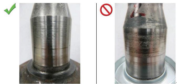
Inspect and bleed the cooling system thoroughly and ensure that all connections are tight. Replace the turbo cooling lines if needed.

In rare cases the brake pedal may not raise back up or is stuck down after a normal braking event on 2010-2015 Cadillac SRX or 2013-2015 XTS vehicles. The condition may occur in high temperature and humid ity conditions and may not be repeatable. The brake lights will remain on and brakes may drag after the pedal is released. A pop, click or snap noise may be heard when the pedal is applied or released. If the concern is intermittent, allow the vehicle to idle for 30 minutes on max heat and floor mode to try and induce the concern. The condition may be due to a bind in the brake pedal pivot bushing. Replace the brake pedal arm. Be sure to use the two new retaining clips that are included with the new arm.
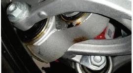
bushings are installed, an assembly lubricant is used. It is possible that over time this lube will weep and appear to be a leak from a bushing that is not hydraulic. Verify that fluid is not leaking from other components such as shocks or struts and clean off the weeping lube. The only hydraulic bushing on 9x1 vehicles is in the lower control arm of the front suspension.
This bulletin applies to Porsche 9x1 sports cars, 2012 to present. Suspension bushings appear to be leaking. When suspension
Some 2012-2014 Edge/Explorer vehicles built on or before Oct. 14, 2013, and equipped with a 6F35 automatic transmis sion may exhibit a fluid leak from the left hand transmission half shaft seal due to wear on the transmission case bushing.
1. Remove the LH half shaft.
2. Inspect the half shaft journal surface finish. If the journal does not have any metal transfer from the bushing, the half shaft can be reused. Use the service kit that contains only the bushing and seal. If the journal has any metal transfer from the bushing, replace the half shaft. The replace ment bushing with the red Teflon coating on the inside diameter of the bushing allows for the reuse of the original half shaft if the half shaft journal does not show any metal transfer from the original bushing.
torques are critical to prevent abnormal noise and ensure safe usage of the skid plate’s integrated jack point.
the TCM (transmission control module).
1. Verify proper shift cable adjustment.
2. Verify proper ECM Park/Neutral switch status in all ranges.
3. Verify proper internal mode switch (IMS) A/B/C/P parameters in all ranges.
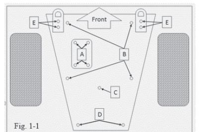
Some 2014-2020 Toyota Tundra trucks with a TRD skid plate may exhibit a creaking or cracking noise coming from the lower front end. The source of this noise has been pinpointed to the TRD skid plate contacting the frame crossmember. Contact between the skid plate and frame crossmember is by design. Do not modify skid plate hardware or add shims, washers, insulating material, etc. Skid plate fastener


Some owners of 2009-2017 Chevy Equinox, Impala, Malibu or Traverse vehicles may comment that the check engine light is on, and in some cases, the PRNDL display may be absent. The technician may nd DTC P182E set as active or in the history in
4. Operate the vehicle within the Conditions for Running the DTC and freeze frame/failure records data in an attempt to duplicate the DTC. If the DTC does not reset, replace the IMS (lever, manual shift detent with shaft position switch assembly). If the DTC does reset, complete the Circuit/System Testing steps. If DTC U0101 is set as active or history in the electronic brake control module, it should be ignored as it has been found to be a false setting.
Visit autoserviceprofessional.com/TSB for additional service bulletins.
ACDC 49 www.fixev.com
Aftermarket Auto Parts Alliance Inc. 39 www.myplace4parts.com
Aftermarket Auto Parts Alliance Inc. IFC www.perfectstop.com
AUTEL 5 www.autel.com
BendPak Inc. 18 www.bendpak.com
BendPak Inc. 19 www.bendpak.com
Bosch Auto Parts 13 www.boschautoparts.com/reputation
Bosch Auto Parts 24-25 www.boschautoparts.com/reputation
Bosch
www.otctools.com

www.federatedautoparts.com/toysfortots.aspx
Lang Tools 17 www.langtools.com OTC Tools OBC www.otctools.com
Raybestos 28 www.raybestos.com
Raybestos 29 www.raybestos.com Noble6 43 www.noble6.com
Tekmetric IBC www.tekmetric.com/multishop
Gain back time, make better decisions, and maximize your margins at each and every shop.
Make better decisions for your business by monitoring your shops' performance using one, central reporting suite.
Track shop performance using metrics that are important to you
Compare the performance of your shops, side by side, to drive key business decisions and replicate what's working well in your highest performing shops.
Simplify your multi-shop data management


Save time as you grow by managing key data for all of your locations, all in one place.


tekmetric.com/multishop

Expand your business with our most powerful set of tools and reports to easily and efficiently manage multiple shops.
• Lifetime warranty
• Jack design tested to comply with safety standards as defined by ASME PASE-2019
• Stand designs tested to comply with safety standards as defined by ASME PASE-2019
• Light-duty 2-ton to heavy-duty 22-ton capacities
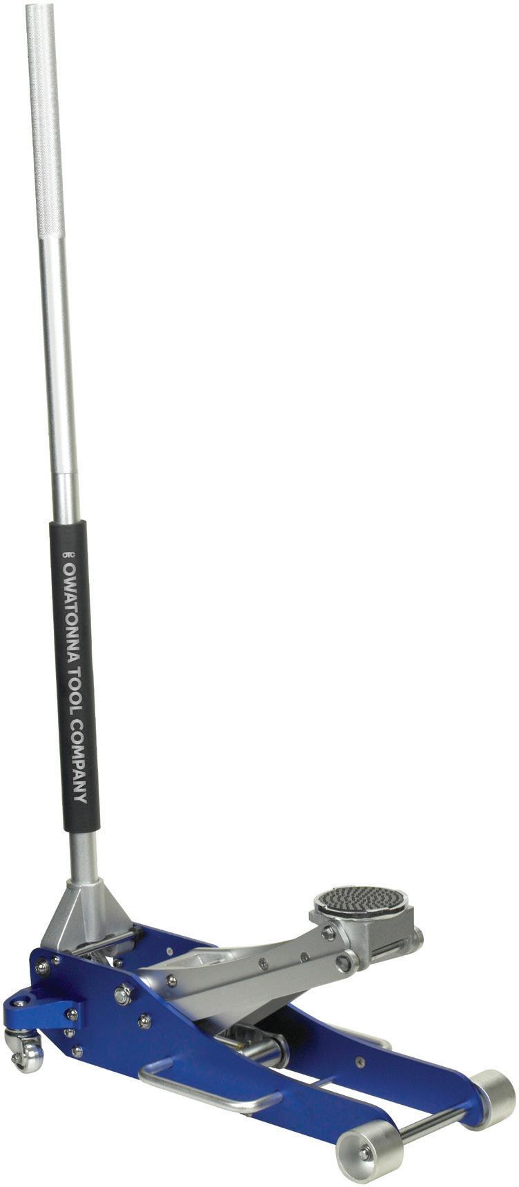

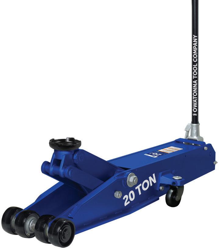
• Padded handle to protect bumpers and rocker panels (LDJ Models Only)
• Product capacities durably marked for proper application
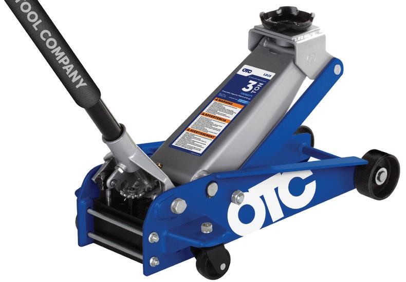

OTC jacks and stands are proven to meet the safety standard for Portable Automotive Service Equipment (PASE-2019). What does PASE mean to OTC? Every jack and stand design is tested to meet every PASE-2019* test, not just one.
Service jacks undergo a series of 5 tests:
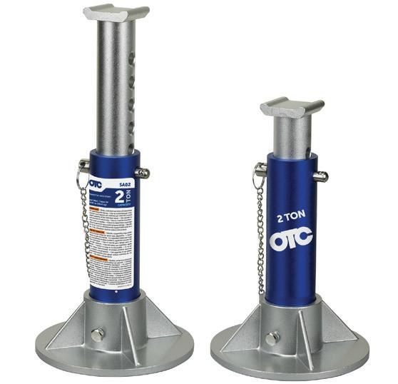
Load Sustaining Test: Jack will not inadvertently drop under load.

REMEMBER: Use OTC Stands to support a load – not a jack.
Load Limiting Test: Jack will not lift a load beyond its rated capacity
Release Test: Jack can be lowered gently
Periphery Test: Jack avoids tipping when load is not centered on saddle.
Proof Load Test: Jack structure supports 150% of rated capacity
Off Center Load Test: Limits allowable deformation when stand is placed off center.
Proof Load Test: Stand structurally limits allowable deformation at 200% of rated capacity.
*Bosch testing to ASME PASE-2019 standards, conducted in Owatonna, Minnesota January – October 2019