ULTRA SERIES


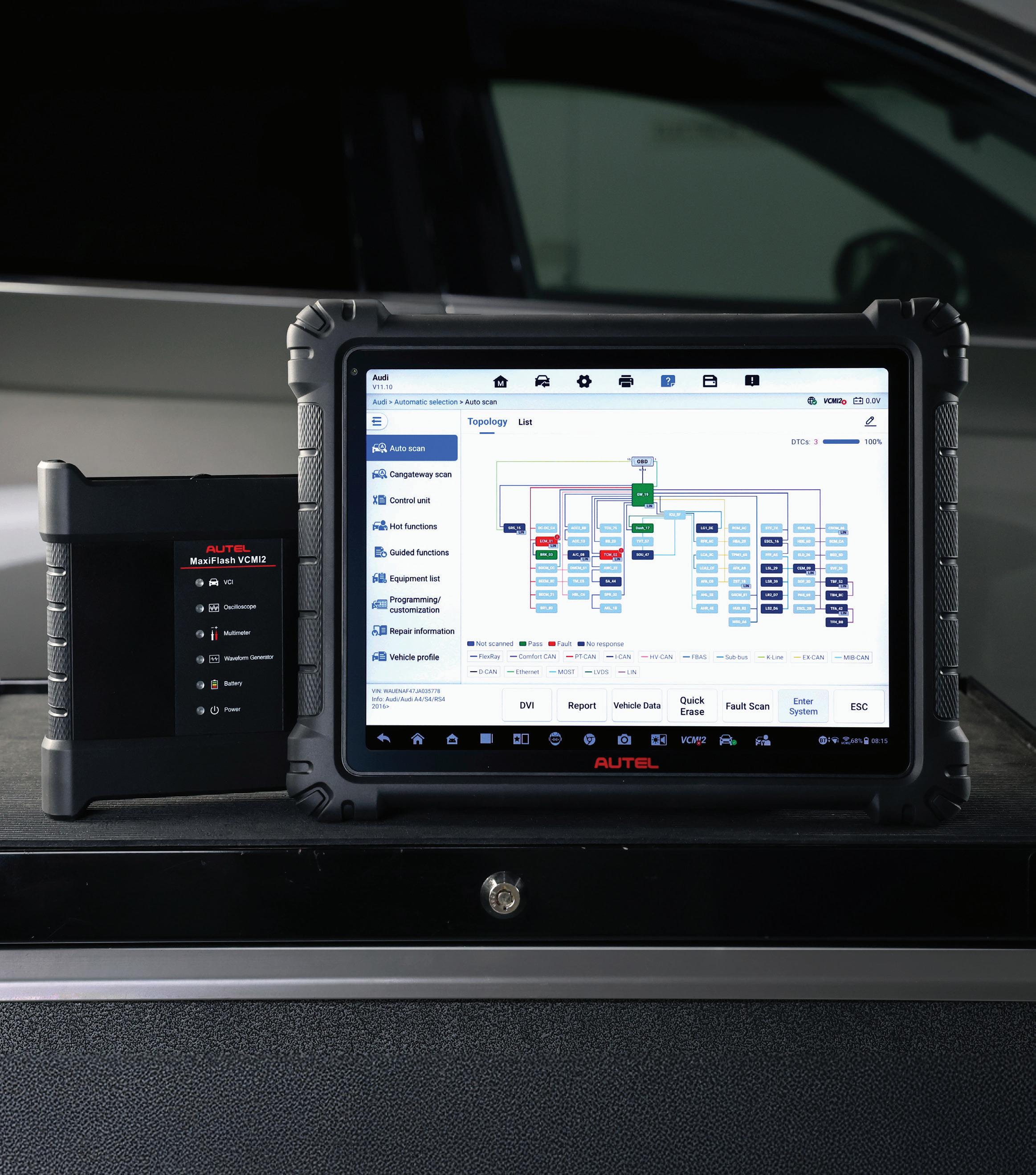


Photo courtesy of Autel


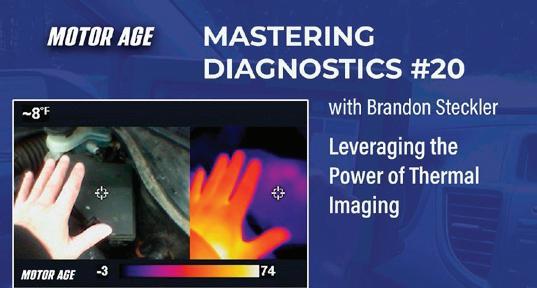
In this episode of Mastering Diagnostics, Motor Age Technical Editor Brandon Steckler describes how he leverages the power of emissivity to make light work of some diagnostic situations.
To view this video, visit VehicleServicePros.com/55263380


This blog explores why ADAS recalibration matters, the different types of calibration required, and how Snap-on diagnostic platforms equip technicians with the service information, guided workflows, and exclusive features to complete these complex jobs.
To read this blog, visit VehicleServicePros.com/55328857


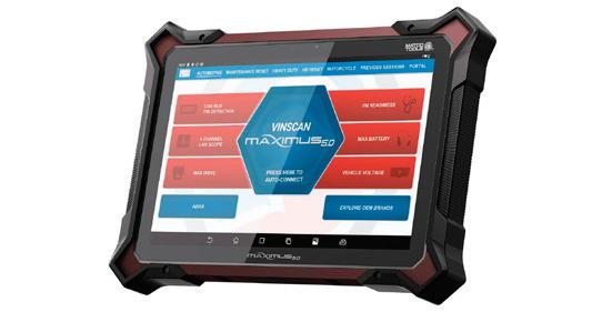
Tool Review: Matco Tools Maximus 5.0
Chris Martino, owner of ADAS L.I. in Amityville, New York, reviews the Matco Tools Maximus 5.0 scan tool.
To read this review, visit VehicleServicePros.com/55285469
Blindly approaching a fault is like jumping into an empty pool ... you may quickly get to the bottom of it, but it’s probably going to hurt.
By Chris Farley
Irecently encountered two vehicles with technician-induced problems that I believe offer some valuable lessons. Whether we caused the problem or we’re there to diagnose it, rushing and jumping to conclusions often costs us more time in the end.
The customer brought in a 2013 Ford Focus for an intermittent no-crank condition.
My usual diagnostic routine is a pre-scan, a quick visual inspection, and an interview with either the shop owner I’m called to assist or the vehicle owner. But as usual, I got only part of the story, even after thorough questioning. I’ll never understand why this happens.
The shop tested the car and didn’t find anything wrong, so it returned the vehicle to the customer. A week later, the vehicle returned to the shop on the hook of a tow truck. The customer stated that the vehicle had refused to start a few times, and this time it had died on the road. The technician at the shop approached the vehicle, and it started right up. The tech believed the starter must be the culprit. This is not a logical direction to head in for a vehicle that suddenly died on the road.
The shop owner told me they installed a starter, lowered the vehicle to verify it started, and then raised the vehicle to install the underbody shield.
Figure 1 This prescan from my Snap-on Zeus+ shows which modules are communicating. But more importantly, it also shows the ones that are missing.
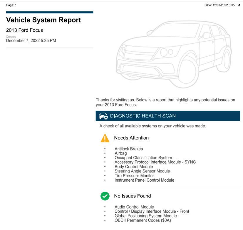
They then lowered the vehicle, and it again failed to start. They tried to scan the vehicle and found it would not communicate. They decided to push the car out and give me a call.
I connected my Snap-on Zeus+ scan tool, and the first thing I noticed was that the vehicle did not auto-identify with the scanner. I manually selected the vehicle and reestablished communication with some of the onboard modules. Now, this is where I’m guilty of having jumped the gun. Since I received the call, all I could think of was the common fault for the symptom that these vehicles experience, a faulty transmission control module (TCM).
Sometimes we need to be reminded of why we have a diagnostic process, and we need to be humbled when we get lazy or ignore it. Although I followed my process, I wasn’t focused because I had
already convinced myself the problem was a failed TCM before I even connected my scanner.
It was a rainy day, and I was in a parking lot. But in my head, I believed all I had to do was unplug the TCM and I’d see vehicle communication return. So, I laid down in the rain and unplugged the TCM, but communication had not returned. For the rest of the day, all I had to show for my effort was wet clothes. Now that my bubble had burst, I got to kick myself and regroup. I went back to my process and I reviewed my scan report (Figure 1). I noticed that the power steering control module (PSCM), the powertrain control module (PCM), and the transmission control module (TCM) are the only modules missing from the bus. At this point, I reviewed the system wiring diagrams, and since I already had the TCM unplugged, I started my testing there. I tested to verify the TCM had everything it needed
to communicate (voltage supply, ground supply, and communication signals coming in). The only issue I noted was the signal from the high-speed CAN bus low (Figure 2).
My next step was to install my AESWave LineSpi breakout box. I connected the Snap-on scope (Zeus+) and saw the same high-speed CAN low pattern, so then I performed a resistance check on the high-speed CAN network. This test checked the integrity of the circuit and offered me direction.
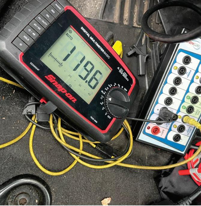
To perform this test, I turned the key off (so the network isn’t active) and connected my Snap-on DMMacross high-speed CAN+ and CAN-. You should anticipate a 60-ohm reading displayed. However, that is not the reading we were getting here, which tells us there was an incomplete circuit and one resistor was bypassed (Figure 3). I then retraced my steps to decide on which direction we should go:
• The scan report showed that the PCM, TCM, and PSCM were offline.
• A resistance test proved a circuit was open in the high-speed CAN network.
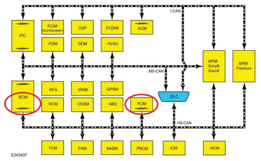
A review of the CAN system topology I sourced for this vehicle from ALLDATA showed the terminating resistors for this network are located in the body control module (BCM) and the PCM (Figure 4). But of those two, only the PCM failed to communicate.
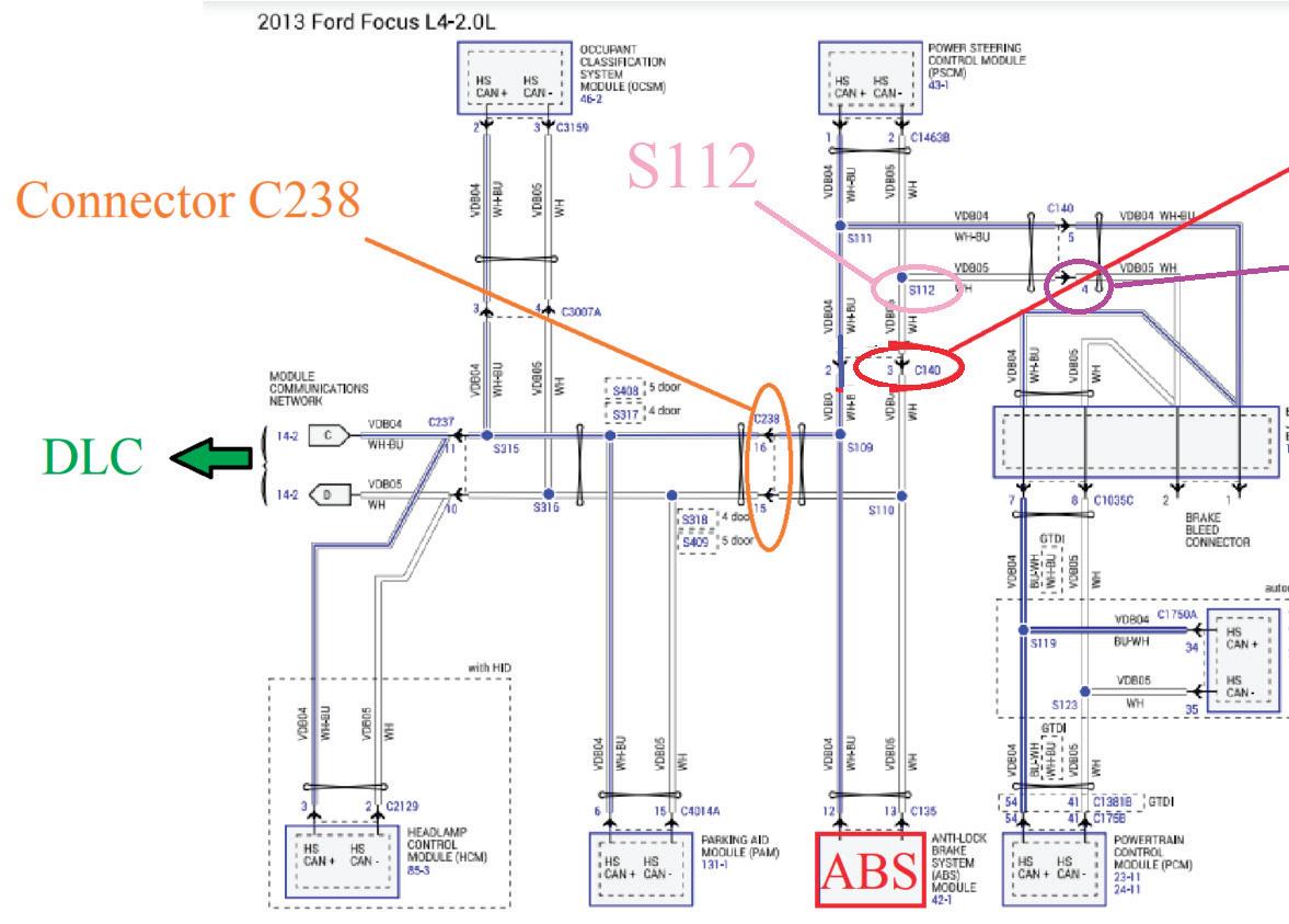
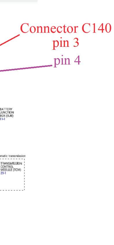
I looked at the CAN bus network diagram (Figure 5). The communication wires pass through connector C238 to splices S109 and S110. From there, the circuit heads toward the ABS module and to connector C140. The ABS module was communicating, so I realized wiring integrity was good up to that point.
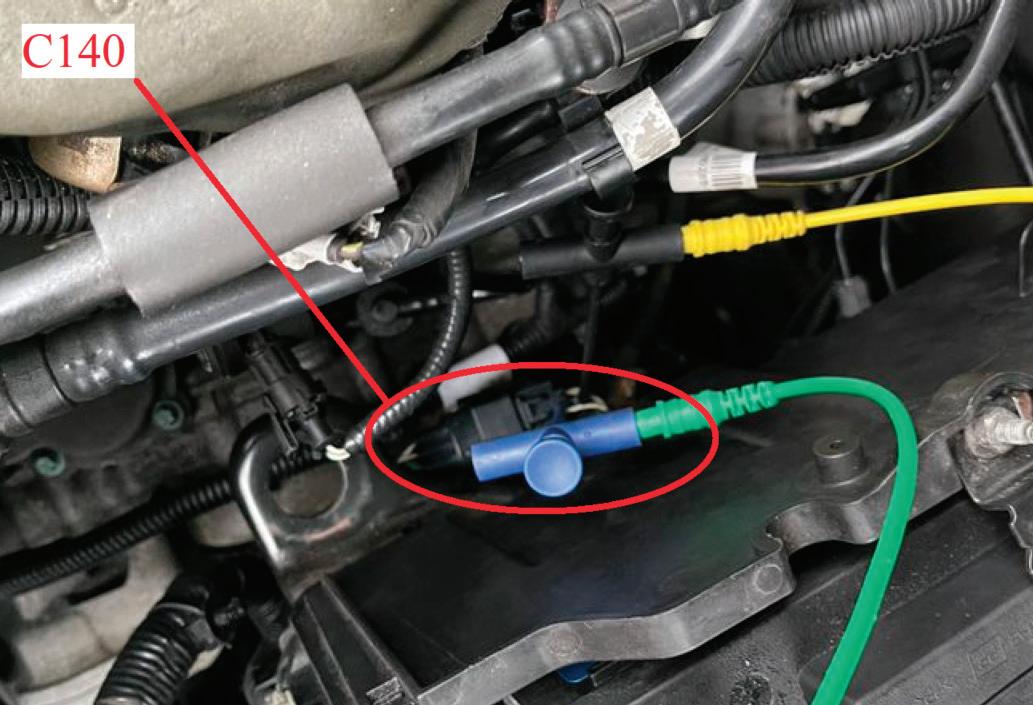
The next best place to check our signal is connector C140, which is located alongside the battery. I’ve accessed the high-speed CAN- wiring at pins 3 and 4 with my pierce probes from AESWave (Figure 6). The circuit comes through pin 3 to splice S112, which splits the circuit (to the PSCM and back through C140 pin 4/out to the PCM and TCM).
I performed another resistance test at connector C140 (pins 2 and 3) and measured 120 ohms, but pins 4 and 5 displayed an open circuit. This confirmed the fault was between the two chosen test points.
I jumped pins 3 and 4; communication returned, and I could talk to all
modules. I then knew I would find my circuit issue between S112 and C140.
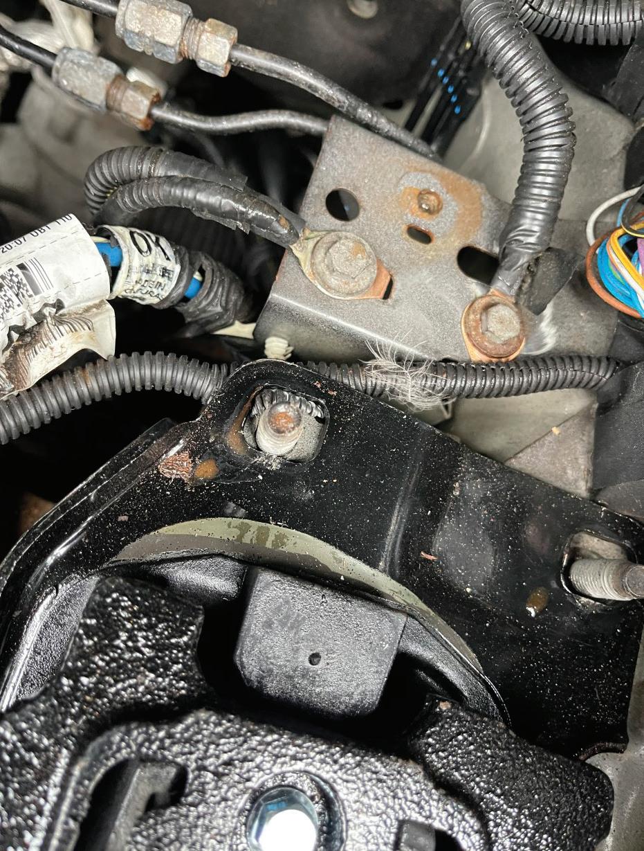
To access that section of the wiring, I removed the battery, covers, and tray. Once they were removed, I saw a shiny new transmission mount looking at me. The wiring harness comes out of C140 and goes along this mount before S112. I disconnected C140 and tried to move the harness to gain access for testing, but it was pinched under the mount.
I questioned the shop owner about the new mount. Suddenly, his memory came back, and he told me he had replaced the mount after he confirmed the starter was working (I’ll never understand why it is so difficult to get the whole story up front).
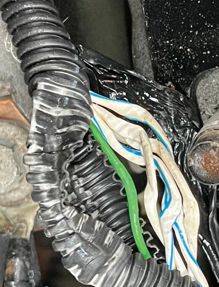
After removing the bracket, I freed the harness and removed the conduit from the harness (Figure 7). This is the extent of the damage (Figure 8). With only a slight tug on the wires individually, two of the wires instantly pulled apart. The shop let me repair the wiring, which allowed me to test the vehicle again after repairs and confirm everything was working properly at that time. I add the “at that time” reference because I know their repair caused this no-start issue, but I don’t think the starter caused the previous issue of the vehicle “died while driving.” We may never know the root cause of this vehicle’s stalling issue, but time will tell.
I got a call to look at a 2021 Jeep Grand Cherokee with multiple indicators illuminated and a handful of DTCs. It was hit hard in the right rear of the vehicle, and the shop had already replaced a physically damaged module in that area. But when I got to the vehicle, it seemed

all the original faults remained.
The shop owner told me he called another mobile guy first, and when he saw all the codes (63 to be exact), he turned the job down. When I asked about the replaced module, all he could tell me was that it was behind the right rear interior panel. There are multiple
modules in that location, but they couldn’t be any more descriptive. And of course, they threw out all the old parts. The good news is the odometer was flashing (for those of you who haven’t seen that yet, it means a module in the network needs a proxy-alignment/ configuration). This is a procedure that transfers the vehicle configuration from the BCM into the new module that was installed.


Software on Bosch ADSX Diagnostic Scan Tools is more powerful & flexible than ever before.
• Trusted OE Platform: Powered by Bosch, the OE leader—ensuring accurate diagnostics and fewer comebacks.
• 98.5% Coverage: One Software, All Vehicles: Broad coverage across domestic, European, and Asian makes—plus EVs and ADAS-equipped models.
• Efficient, Repeatable Workflows: A consistent user interface across all makes & models helps reduce learning curves and increase throughput so technicians can focus on fixing cars, not learning a new tool.
• Actionable Reporting: Generate customizable pre- and post-scan reports with shop name, RO number, and full system status in seconds.
• Flexible Subscription Options: Tiered plans (Basic, Enhanced, ADAS*) let you scale capabilities based on shop needs and budget.
• Tech-Ready Features: Built-in Google Search, Identifix®, AllData® and Mitchell® links to streamline research and repair time plus access to Google Play Store.
• Protected Investment: Never lose capabilities— ADSX platform unlock access to OE-licensed Secure Gateway Modules (SGW) for OEMs such as FCA/ Stellantis, Nissan Ariya, Hyundai, Kia, Genesis, Ford/Lincoln, Honda/Acura, Subaru, Porsche, and Volvo vehicles, plus supports J2534 passthroughs.
• One-Tool Efficiency: AutoID, DTCs, resets, relearns, and bi-directional tests— all in one platform, built to minimize unnecessary tool switching.
*ADAS capabilities on the ADS 625X only.
I connected the factory interface (Micropod3) to the vehicle and ran the proxy procedure. The scan tool alerted me that the power liftgate module wasn’t aligned, so now I knew which module was replaced. I performed the procedure, and I cleared the DTCs. I was then left with only seven remaining DTCs (four for rear parking sensors shorted to ground, two for rear radar blind spot circuits open, and one for private CAN network in the central ADAS decision module (CADM)). In a situation like this, I typically choose one code and chase only that one DTC’s root-cause fault. In this case, I chose the rear radar module, a circuit open (C00C4-13).
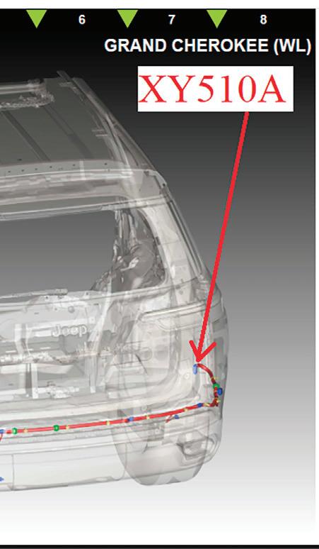
First, I asked the shop to remove the bumper so I could gain access to the wiring and modules. In factory service information, the set conditions for this DTC are as follows: “The CADM detects a power supply circuit for the left-rear mid-range radar.” A check of the OEM wiring diagram shows voltage coming in through connector XY510A pin 10 (beige/red wire) (Figure 9)
The connector is on the passenger side of the bumper and has plastic covers over both sides, making it nearly impossible to see the colors of the wires. When I removed the covers
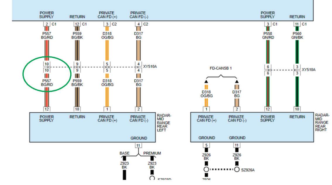
from the vehicle side of the harness, I found voltage available at pin 10, but no voltage available at the radar unit. I then removed the cover from the harness on the bumper side, and I found no wire in that connector cavity. The wires that are present did not match the colors indicated in the wiring diagram.
I had another conversation with the shop owner, and he confirmed he had replaced the bumper harness. I decided to inspect the parking sensor wiring and found it was routed through connector XY511A (which is the connector on the driver’s side of the same bumper harness) (Figure 10). I removed the covers
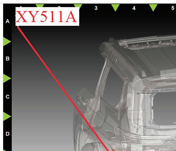

from connector XY511A to inspect the wiring. A beige/red wire at pin 10 on the bumper side of the connector was mated to an empty cavity in the vehicle side of the harness. I wouldn’t have guessed this from the start, but this was a case of the bumper harness having matching connectors on both sides. This allowed it to fit (with all the connectors going across the bumper, for parking sensors) with the wire in either position. Strangely enough, there were no fitment issues, and the only way you could tell there was a difference was if you looked at the terminals in the connectors. A quick swap of the harness, clearing the DTCs, and we had a functioning parking and radar system with a clean post-scan.
Both case studies were shop-inflicted issues that could happen to any of us when rushing to complete a job. Whether it is attempting to drive efficiency up or the pressure we get from impatient customers to get their car back, spending a few extra minutes on either of these jobs would have prevented these issues. They also show how following a diagnostic process and not jumping the gun saves time in the end, even if you are up against 63 DTCs!


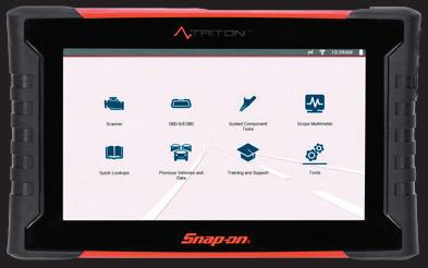
Stronger in numbers. Add yourself to the equation. Miguel isn’t one to ask for help. Equipped with The TRITON™, which provides verified fixes harvested from users across the globe, he doesn’t have to. Offering a 2-channel lab scope and wireless connection, it’s like having 70 thousand techs, each with 40 years of experience at his side. So you can cover Miguel’s back, and he’ll cover yours. Plus up your numbers with the diagnostics system that adds you to the equation.
By Austin Spencer
It’s impossible to scroll through your social feed, watch the news, or browse the internet without artificial intelligence (AI) creeping into the conversation. And for the most part, the headlines about AI seem grim. Some recent “for instances” include:
• FOX Business: Layoffs in October hit highest level for month in 22 years as companies cite cost-cutting, AI
• CNBC: AI-washing and the massive layoffs hitting the economy
• Variety: Rise of the AI job-killing machines
• The New York Times: IBM to cut thousands of workers amid AI boom Reading enough headlines might give you an uneasy feeling that something eerily close to the Terminator film franchise is afoot. Are we stuck in a time loop? Is Arnold going to visit us from the future to save us from ultrasmart machines set to systematically wipe out humanity?
Of course (fingers crossed) not. But let’s not discount the fact that AI is having a very real impact on the business workforce right now. Writing, computer programming, accounting, research, and even acting seem to be the frontline casualties of the AI surge.
But what about auto repair? Are AI robots going to start wrenching on cars?
Probably not.
Some people at the top of the automotive food chain tend to agree that auto repair is, and will remain, in high demand. Ford’s CEO, Jim Farley, has been very vocal lately about the dwindling number of skilled craftsmen in

Is it possible that AI will handle automotive repairs in the future?

the workforce. For all the talk about how AI will wipe out white collar jobs, he believes too little attention is being paid to skilled crafts like HVAC, plumbing, construction, and, of course, auto repair.
In a LinkedIn post on June 2025, Farley highlighted the fact that the US needs 600,000 more manufacturing workers, 500,000 construction workers, and 400,000 automotive technicians.
“Right now, the problems we’re trying to solve are pretty practical. I need 6,000 technicians in my dealerships on Monday morning,” he says.
Another respected voice in the automotive industry agrees.
Regarding AI’s impact on automotive repair, Haakan Light, the manager of training and development at TOPDON U.S. says, “The future of AI in auto repair isn’t one of human replacement, but rather one of collaboration. It’s simply like every other diagnostic tool in the toolbox. You must combine human intuition and ‘gut feelings’ with AI’s complex computation power in order to understand its limitations and maximize its capabilities.” Light,
who traverses the country training auto technicians, believes AI is a mixed bag of opportunity.
“I already see the front office embracing AI more so than the shop itself. Answering phones, helping with accounting, and setting appointments offer limited risk and have the potential to streamline front office operations,” he notes. “But when we get into the technical operations of the repair shop, there’s some danger in relying wholly on AI technology.”
One of the “for instances” Light offers up is when he used a premium subscription, which taps into more advanced AI models. He wanted to see if it could correctly diagnose and provide a workable solution for a mechanical issue on a vehicle he was repairing.
“I fed the AI model a bunch of information about the problem I was experiencing,” he says. “As a professional with a wide amount of experience and training and deep subject-matter knowledge, I looked at what AI spit out and knew the solution couldn’t be accurate.”
In fact, Light sent AI back to the drawing board by telling it, “Your analysis is backwards. Lambda values above 1.0 are lean. Lambda values below 1.0 are rich. Please recalculate your analysis.”
AI responded with, “You’re absolutely right – my bad. Reworking the snapshot with that in mind.”
The fact that AI responded back with “my bad” is, in and of itself, quite hilarious (Figure 1). But, as humorous as the response may be, AI still made a fundamentally inaccurate assertion and analysis based on the initial inputs. But it was Light’s experience that coursecorrected the solution. By leaning on his experience and working through the specific issue with AI, the fault turned out to be a drivability-related issue for fault code P0131: “02 sensor circuit, bank 1, sensor 1, - low voltage.”

Figure 1 — Light has to correct AI, and it responds with "my bad." Using your own experience is crucial while utilizing AI as a tool. Photos courtesy of TOPDON
statistical probability. But someone still has to roll up their sleeves and put in the elbow grease.”
In a separate case, a customer approached Light’s colleague, a professional auto diagnostic technician, with all the reasons why his engine light was on – based on a ChatGPT query, of course. While the issues identified by ChatGPT were plausible causes for the engine light being on, only additional tests could prove which one of the issues it was – or if any of them were even valid.
Which, by the way, they weren’t.
Turns out the problem was a mundane and simple vacuum leak. A solution that didn’t even make his customer’s ChatGPT list.
“No matter what the AI model computes or spits out, testing is still required to prove what the problem is,” Light adds. “Sure, AI can help identify tactical problems and shorten the path from issue to repair based purely on
That’s because automotive repair isn’t just an intellectual exercise. By nature, it’s very physical. Working on a vehicle is not a repetitive task, like bolting screws on a chassis assembly line. It requires a high level of critical thinking, human intuition, and manual labor. Something that robotic AI labor can’t perform.
Where Light finds AI to be most useful regarding automotive repair, is in the aggregation and analysis of data. Feeding AI data and asking it to look for patterns is something it can do very well – and exposes a technician to less risk - while augmenting efficiency.
For example, AI helped Light spot a pattern from multiple diagnostic scans on the same vehicle. The synthesized AI report concluded that “the Gateway [19] retains all network fault memory and is likely the root hub of communication failure.” The recommended next
steps, which, this time, turned out to be helpful in isolating the problem, included checking network instability, power-supply issue, ground/reference drop, and gateway overload. According to Light, the failure on the vehicle was in fact a defective J533 Gateway Control Unit.
“Let’s say you upload a number of SAE PDFs, you can ask AI a specific question related to those documents that can lead to a more accurate response,” Light says. “You can also ask AI to ‘water it down’ or summarize the documents so you can cut through the clutter and get to the more conclusive and critical parts of the documents.”
Light also suggests that AI can be used as a more advanced search engine. Since some AI models are connected to specific automotive resources, like technical service bulletins, AI may be better able to help find that information faster than a traditional browser search.
Light’s understanding and experience with AI is helping TOPDON roll out
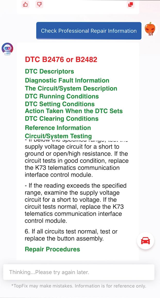
the company’s new TopFix AI scan tool. To explain how this new tool will work, Light gives the example of working on European cars. “Mechanics who repair European makes usually don’t get enough information from the manufacturer about what a trouble code is, or how it’s being defined,” Light says. “TopFix AI can be used to search for extended definitions and additional information on a fault code directly from the OEM. “For example, if 5,000 technicians are asking the same questions about a specific code, TopFix AI can aggregate the data and provide a higher level of insight into the specific system or component that’s most often associated with the trouble code. It’ll behave similarly to a more sophisticated search engine. The difference is that it will be available through the scan tool itself. That is a game changer.”
TopFix AI, which was introduced at this year’s SEMA Show, will give techs struggling with a repair additional ideas or pathways to start. It can find a bulletin, for example, that’s tied to the specific fault code in question (Figure 2). While it’s not designed to replace a technician’s ability to solve problems, it can give immediate information or feedback that can streamline repairs instead of spending time on exhaustive searches online about the problem.
But what separates TopFix AI in the marketplace is the fact that it’s been developed by automotive professionals, not software engineers. So, it’s specifically designed to help auto technicians who struggle with common repairs, not just perform random, pre-programmed functions.
Light’s hope for AI in the automotive repair space is that it will become a productivity or efficiency tool. “As a trainer, we want to teach everybody how to use their tools effectively, he notes. “Whether we’re talking about a
battery tester or charger or scan tool, AI should be seen as just another tool in the toolbox.”
Automotive repair is unpredictable, at best. While vehicles over the years share common engineering, transmissions, fuel, braking, exhaust, and suspension systems, they can be wildly different between vehicle makes and models. There are literally hundreds of thousands of complex components and parts to each vehicle. The idea of asking AI to accurately diagnose and properly identify the solution to an engine light warning is highly unpredictable.
Where Light sees AI as most likely to help the automotive tech is in creating greater efficiency.
“If you can ask AI to retrieve the vehicle manufacturer wiring diagram for a manifold air pressure sensor and have it downloaded directly to your phone,” he explains,” that can have 10 times the value to augment productivity and day-to-day workflow.”
It would be great if AI could tackle diagnostic repairs more efficiently. But maintenance and repair are still going to fill the bays more than specialized diagnostics services. If we can simply ask AI to log into a subscription account to parse service information and retrieve an accurate wiring diagram, Light believes it would be a massive time saver.
While AI can touch many aspects of automotive repair, the nuanced and hands-on nature of the job, not to mention the complex problems presented by vehicles with little to no computerized systems, will remain an essential part of the auto repair process.
“As I see it now, AI is not going to replace the person who is technically trained and who practices every day using their tools,” Light adds. “As I
cross the country training technicians, one of the primary concepts I teach is critical thinking. That’s because modern vehicles are highly complex systems of mechanical parts, sensors, electronic components, and software. Nothing can replace that human intuition that comes from observing the sound of an engine knock or the burning smell of a slipping belt.”
So, what’s the takeaway? If you’re an auto technician, or plan to become one, rest assured that it’ll be years…if ever… before AI robots can replace you under the hood or beneath a lifted car.
Now, whether Arnold’s going to jump through a time loop and take your job decades down the road? Well, we’ll just leave that storytelling to Hollywood.


By understanding your tools’ limits, you’ll be better able to wield them to your advantage.
By Brandon Steckler

Every tool you own has a limitation. It’s easy to see with something like a ratchet—a short one doesn’t provide enough leverage for high torque, while a long one makes it hard to feel low torque accurately. The same holds true for diagnostic equipment. Contrary to popular belief, it doesn’t matter how much or how little you spend on diagnostic tools — every single
one has its limitations. And if you don’t know what those limitations are — what the tool can and cannot do — you’re in for a world of hurt. You’ll end up relying on that tool for information, and even if you understand what you’re looking for, if the tool can’t accurately show what’s happening within a component, system, or circuit, you’ll be working with bad information.
One thing I want to point out is that tools, if you really think about them, become an extension of our mind. They allow us to behave like the scientists we are. Once we understand how individual components work, we can see how they come together as a system to accomplish a goal. From there, we can carry

out tests to determine whether a function was performed correctly, either by a single component or by the system as a whole.
We form hypotheses based on our fundamental knowledge of what should be happening, and it’s our tools that let us test those hypotheses and reach diagnostic conclusions — whether something’s broken or everything’s fine. The tests we perform give us the answers we’re looking for. But that brings us back to the point about limitations: if we don’t know what a tool can’t do, we may rely on it for information that isn’t correct. And even if we know what we’re doing, bad information still leads to bad diagnostic decisions.
We’ll be testing tool limitations based on what I’ve learned over the course of my career about implementing tools. I’ll be carrying out some tests — essentially taking these tools for a test drive — to see what they can do and, more importantly, what they can’t. By pushing them to their limits, we can better understand what’s really happening within the components and circuits we’re testing.
We’ll use several tools — a test light,
a digital volt-ohm meter (DVOM), and a lab scope. Each of these offers valuable information when used correctly, but each also has limitations. I want to show you what those limitations are and how to identify them for yourself.
This matters because if you’ve ever watched a truly skilled diagnostician, it looks effortless — almost like a game. That’s because they know how to implement their tools the right way, using them as extensions of their mind to test hypotheses and make accurate diagnostic decisions quickly. But when a diagnostician doesn’t understand what their tools can and can’t do, that’s when bad decisions happen.
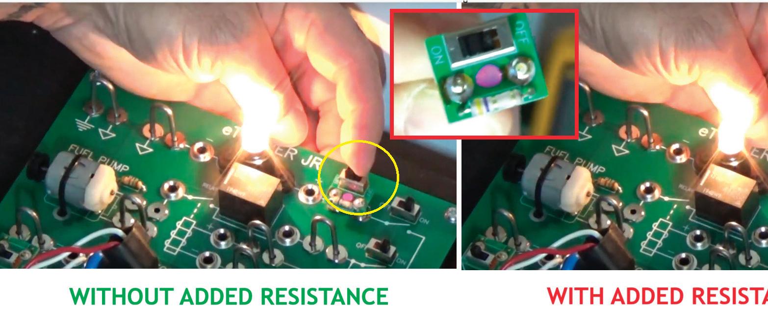
Let’s take a look at a functioning light bulb circuit. It’s simple — a switch to turn the circuit on and off with no other resistance in place besides the light bulb itself. What we have here is essentially a switched resistor; we can switch the resistor in or out of the circuit. When the resistor is switched off, it acts like a fusible link, bridging the gap in the circuit board.
Now, the light bulb’s resistance measures about 7 ohms. Check out
Figure 1 to see the change in brilliance of the bulb as I switch in the resistor. You can see a slight change in brightness, but it’s so small that if you blink, you might miss it. The bulb still appears nearly the same, even though we’ve added resistance.
In this circuit, we can see the bulb illuminate to a certain brightness. But our eyes can’t measure that brightness precisely. When we added resistance nearly double the bulb’s own value, the change in brilliance was minimal because the circuit already has relatively high resistance.
The point is that the light bulb here can represent an incandescent test light or a noid light we might use on a fuel injector circuit. The bulb illuminates, so we assume the circuit is healthy. But as this test shows, even when resistance doubles, the light still appears the same — potentially misleading a technician into thinking the circuit is fine when it’s not.
Let’s take this a step further and apply the same fault using a different tool. This time, we’ll use an ohmmeter to measure the resistance of both the light bulb and
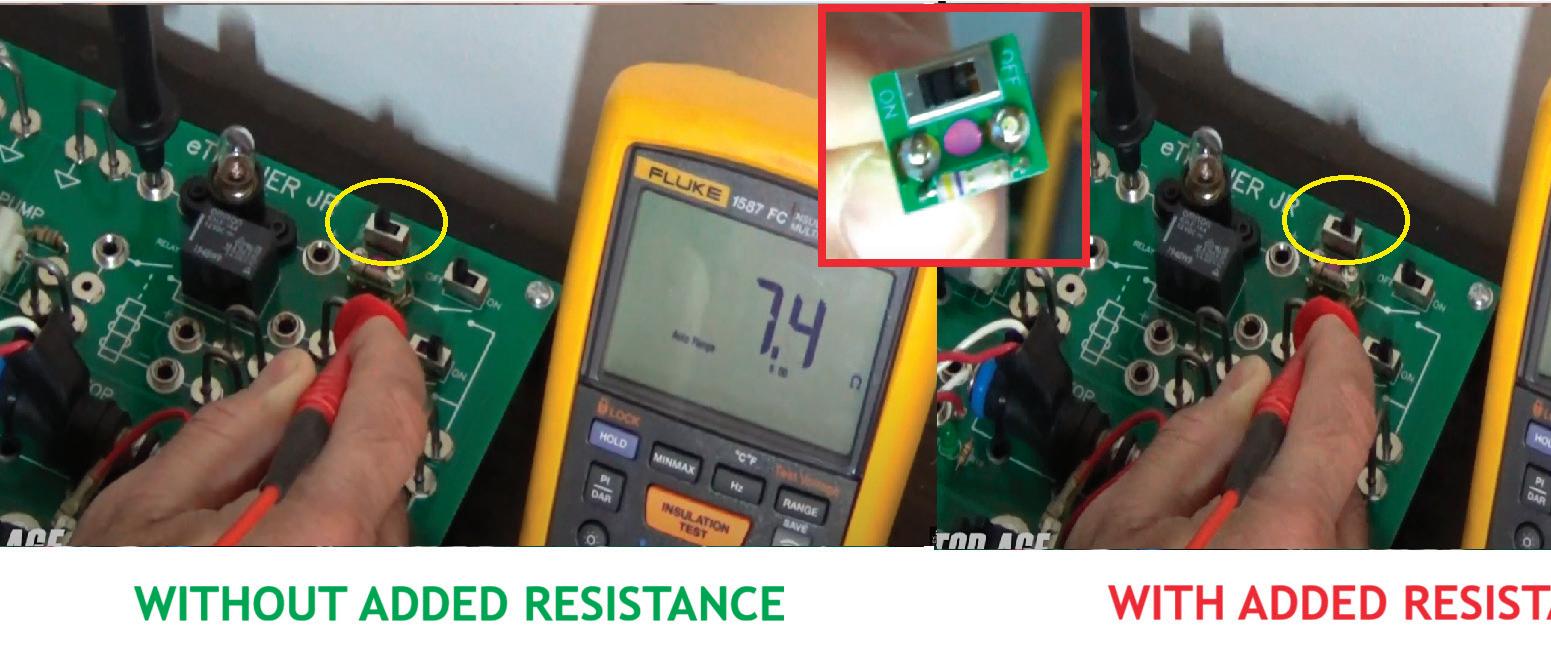

the added resistor. Remember that the light bulb alone measures about 7 ohms. When we switch the resistor into the circuit, the total resistance increases by nearly 50 percent (Figure 2).
You can see that the ohmmeter clearly shows the issue, while the test light did not. The light still appeared nearly the same even though resistance doubled. The ohmmeter, however, revealed an increase in resistance, pointing to a fault in the circuit. It doesn’t tell us where the fault is — that would require isolating components — but it does confirm a
resistance problem.
Now, what if that same fault existed in a circuit that functioned, but not well — a more dynamic circuit that switches on and off rapidly? In that case, an ohmmeter wouldn’t be the right tool.
Looking back at our circuit, the red lead measures the voltage feed, and the white lead measures the ground side, or injector driver control. Since this is a ground-side driven injector, there’s no voltage when the circuit is inactive. When we turn it on, the DVOM shows

nearly source voltage — about 12V. Using the DVOM’s Min/Max mode, we see a highest reading of 12.12V and a lowest just under 12V, less than a 200 millivolt difference.
You might wonder, ‘How can that be?’ The capture rate of the DVOM is simply too slow to register the quick changes happening in the injector circuit. The ohmmeter could only show that a problem existed, not where. To pinpoint the fault, we’d have to open the circuit and test at different points. But with a more dynamic test, like a voltage drop test, we can allow current to flow and measure voltage across the circuit in real time. This method reveals faults without disassembly because the circuit is being tested dynamically.
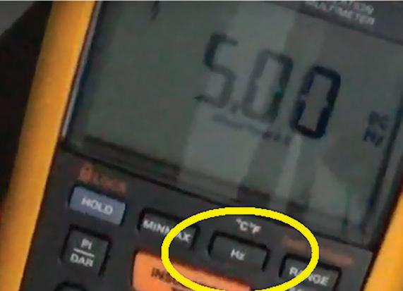
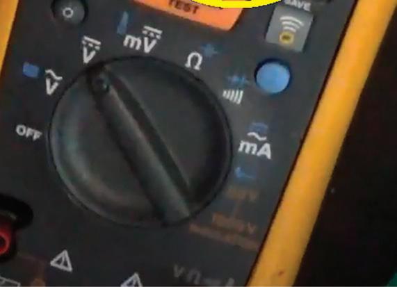
Now let’s look at a circuit that operates dynamically and changes state very quickly. To better capture what’s happening, we’ll use a different function on the DVOM. By pressing the frequency button, we can see it reads 5 Hz — meaning the injector is firing five times per second (Figure 3).
So, let’s do a quick recap. Even though the DVOM is a step up from the simple light bulb brilliance test — and the ohmmeter left us guessing because we’d need to take the circuit apart to
find the fault—voltage drop testing gave us more insight by allowing current to flow dynamically. However, on this fast-switching injector control circuit, the DVOM’s update rate was too slow to accurately capture voltage changes in voltage mode.
By using the frequency function, we can at least see how quickly those injector pulses occur. But remember, the goal here is understanding tool limitations. While the frequency mode shows pulse rate, it still can’t identify whether a fault exists in the circuit. That’s where a lab scope becomes essential.
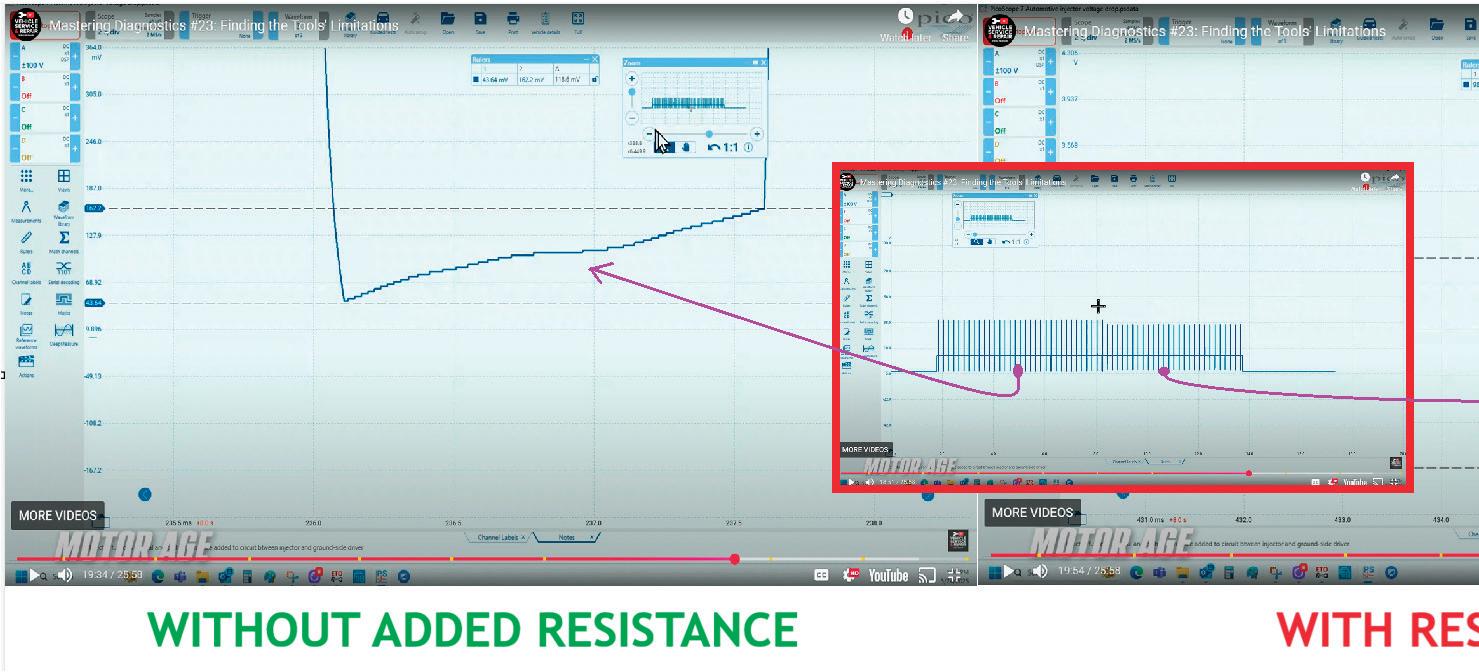
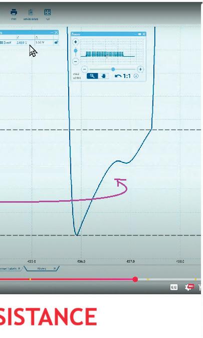
Let's replace our meter leads with the scope leads, switch in our added resistance and review the first waveform


capture from the fuel injector. Remember, the injector was functioning normally until we introduced unwanted resistance.
Looking at Figure 4, you can see the circuit being sampled with the lab scope in the red outlined box. An ‘X’ marks before and after the resistance was switched in. On the left, the injector operated normally; on the right, we introduced additional resistance. This shows exactly what the DVOM showed us — a full injector cycle lasting about 200 milliseconds, which equates to roughly five injector cycles per second, matching the DVOM’s frequency reading.
But now let’s focus on what the DVOM didn’t show us. Looking closely at the voltage drop, the normal injector


waveform shows about a 120-millivolt drop across the injector (Figure 4 – lefthand side), which is completely normal. However, once the added resistance was introduced on the ground control side, the voltage drop spiked to nearly 1.7 volts (Figure 4 – right-hand side), which is a significant change that neither the light bulb test, the DVOM in voltage mode, nor the DVOM’s frequency reading revealed.
Those were the limitations of those tools. The lab scope, however, showed us exactly what we needed to see.
As you can see, the lab scope covers nearly everything we’ve discussed so far. It lets us see available voltage, voltage drop across the injector, injector


pulse frequency, and any corresponding voltage drop occurring away from the injector. That pretty much gives us everything we need to see.
However, we have to remember that every tool has its limitations. Even what many consider the best tool in an automotive technician’s arsenal, the multi-channel lab scope, has its own. The lab scope relies on its high sampling rate — how often it takes a measurement and plots a data point. That overall sample rate is shared among all active channels, so the more channels you use, the fewer samples each channel receives. Likewise, the more time you display on screen, the more those data points must be spread out to cover the full time base.
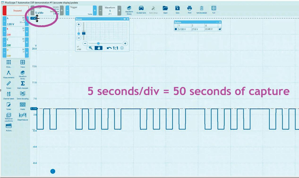
To demonstrate this, we’ll use our simulator board to capture a crankshaft position sensor signal. I’ll capture this in two aspects — one correctly and the other incorrectly — and we’ll take a closer look at the differences.
In the first capture, the scope is set to 5 seconds per division, so about a 50-second sweep. The scope handles this easily, and when we zoom in, the waveform appears as a clean, healthy square wave transitioning between 5V and 0V ( Figure 5), exactly as it should.

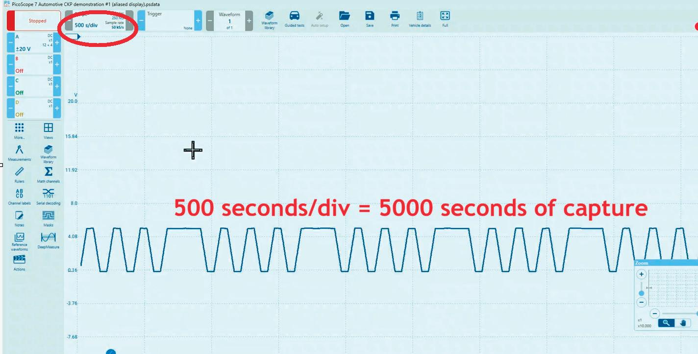
Now, look at the same signal captured at 500 seconds per division. This leaves us with an hour and 23-minute capture. The sample rate is the same, but those samples are now stretched out across a much longer time frame. As a result, the square wave now appears triangulated and distorted (Figure 6), as if there’s a problem with the sensor or reluctor wheel. But there’s nothing wrong with the system at all — this distortion is simply a limitation of the scope.
I don’t know of a scope, at least in the automotive field, that can record an hour and a half of data and still maintain a high enough sample rate to accurately represent the waveform that would be exhibited from a rotating reluctor wheel past a Hall

effect crankshaft position sensor. The transition time between sample points becomes very deficient.
So, what do you think? As you’ve seen, every single tool I showed you does indeed have a limitation. If you don’t take the time to discover those limitations, you’re doing yourself a disservice. It’ll take you much longer to become the efficient, accurate, and confident diagnostician we all strive to be.
Take the time to pull out your tools, test known good vehicles, and push those tools to their limits. Learn what they can show you and what they can’t. Once you understand that, apply those same tests to faulted vehicles
— you’ll see how well the tools serve you once you know their boundaries. A great benefit of doing this is that you’ll start learning to leverage your tools to infer information — allowing you to make accurate diagnostic decisions without tearing everything apart. Relying on your tools to deliver accurate test results saves time while maintaining accuracy, and that’s the goal. These new, more efficient tests will eventually replace the older, time-consuming ones, so make sure you’re staying ahead of the game.
Editor’s Note: This article is based on Brandon Steckler’s episode of Mastering Diagnostics #23: The Importance of Finding the Tools’ Limitations. To view the video, visit VehicleServicePros.com/55283119.


The iSCAN NX from Autoland Scientech can read and clear fault codes, perform service resets and component activations, and has live data streaming and data parameter graphing functionality. It features a quad-core processor for faster operation and two Wi-Fi cards that allow it to connect to the internet and VCI simultaneously. Its diagnostic software covers Asian, domestic, and European models, as well as some medium-duty trucks. It includes bidirectional controls and ECU adaptation, coding, and programming, and it can act as an integrated J2534 Pass-Thru device. The iSCAN NX also features a multi-position locking kickstand and a built-in QR code scanner and camera magnifier.
For more information, visit


The Auggie, developed by AirPro Diagnostics, is a forward-facing camera (FCC) solution for advanced driver assistance systems (ADAS) calibrations. Auggie leverages machine learning and vision technology to accurately replicate ADAS targets and lighting conditions, ensuring precise alignment for proper FCC ADAS calibrations as specified by vehicle manufacturer specifications. Auggie is engineered for user-friendliness and accuracy, enabling dependable calibrations in any environment. Compatible with advanced calibration-capable scan tools, the Auggie mobile ADAS solution streamlines the calibration process, allowing the user’s business to operate more efficiently and improve profitability, according to the company.
For more information, visit VehicleServicePros.com/55252959
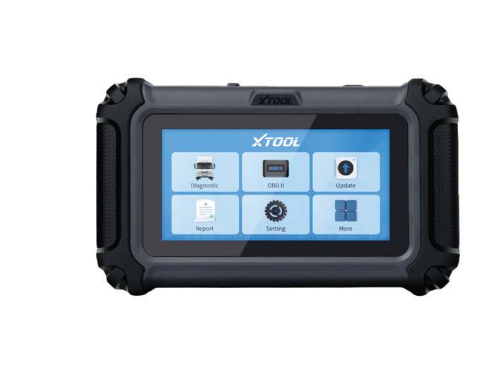
The XTool HDGURU offers heavy duty vehicle diagnostics via standard OBD-II protocols, with over 60 bidirectional tests, more than 35 Cummins dedicated functions, and advanced feature and parameter programming across over 45 applications. It features a streamlined Linux system and a 5.45” display. The HDGURU can provide DTC scanning and clearing, ECU information, live data, freeze frame, and more for Cummins ECUS via OBD-II and 6+9-pin Cummins diagnostic connectors. The tool can also perform various maintenance functions, including special functions, feature activations, and parameter modifications for all major Cummins ECUs. The HDGURU has 35GB of storage and a 3150mAh battery.
For more information, visit VehicleServicePros.com/55322642
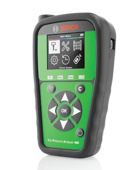
The Bosch TPA 400 is designed for configuring universal TPMS and Bosch QUICK FIT+ sensors. Powered by an integrated OBD module and over-the-air software updates, this tool is compatible with 20 universal sensor brands, including Bluetooth sensors, and boasts vehicle coverage of over 95 percent. Technicians are supported by step-by-step instructions for sensor programming and vehicle relearn procedures, accessible via a 2.8" color display.
For more information, visit
VehicleServicePros.com/55329942
The GEARWRENCH GWSMARTBT provides advanced functionality with full system diagnostics, bidirectional programming, 23 pro reset functions, and live data mapping without any missing features, hidden costs, or financial strain. With comprehensive coverage for over 180+ manufacturers, a 2-year warranty, and free lifetime software updates, it delivers a powerful solution that offers unparalleled value and performance while setting a new standard.

For more information, visit VehicleServicePros.com/55133097
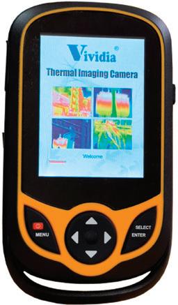
The Vividia T-200 Pocket-Sized Thermal Imaging Camera from Oasis Scientific comes equipped with a 3.2” touchscreen and 256 by 192 infrared camera for high precision realtime thermal imaging. Compatible with PC, iPhone, iPad, and Android devices, a built-in Wi-Fi duplicate display makes viewing the imaging easy for customers or other technicians. The device’s lightweight and compact construction makes it convenient for carrying and use. It has a thermal sensitivity of 0.07 degrees C and can measure temperatures ranging from -4 to 1,022 degrees F (-20 to 550 degrees C).
For more information, visit VehicleServicePros.com/55037337
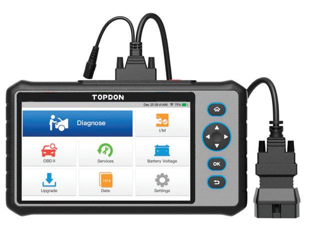
The TOPDON ArtiDiag800 features full system diagnostics for 54 vehicle makes and offers 28 service functions for domestic, European, and Asian vehicles newer than 1995. The ArtiDiag800 has a 7” display, a yearlong warranty, and a year of updates. It also includes AutoVIN technology, one-click upgrades, access to detailed vehicle and software information, the ability to read and clear codes, and the ability to view and graph real-time data.
For more information, visit VehicleServicePros.com/55322105
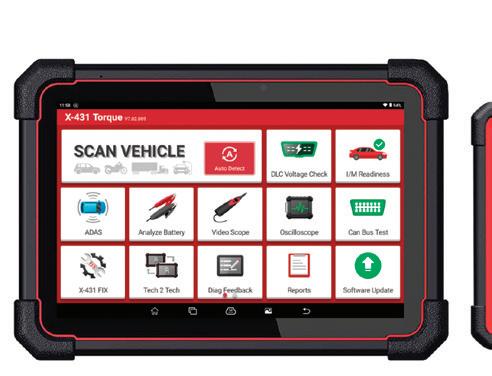

From the shop floor to the fleet yard, the Launch Tech USA X-431 Torque AutoHD Pro scan tool is built to do it all. Whether you’re under the hood of a family SUV or beneath the chassis of a Class 8 diesel, it delivers full-spectrum diagnostics with precision and confidence. Light-duty or heavy-duty, gas or diesel — one connection, endless capability. Why switch tools when one can handle it all?
For more information, visit VehicleServicePros.com/55309027
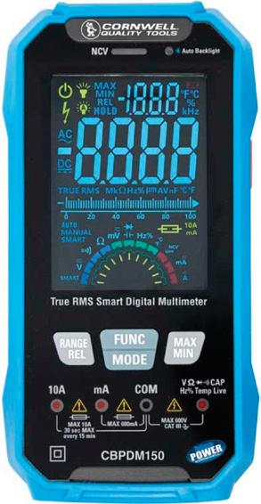
The Cornwell Quality Tools CBPDM150 True RMS Smart Digital Multimeter with Color LCD offers smart meter capability, allowing it to automatically detect if the user is measuring voltage (AC/DC), resistance, or continuity. It features an ultra-fast screen refresh rate, an auto-brightening screen, and dual display. The CBPDM150’s test functions include volts, ohms, continuity, amps, capacitance, diodes, frequency, and temperature. It indicates a blown fuse with an on-screen message, eliminating the guesswork with a 0 amp reading. It measures up to 600V AC/DC, 10A, and 600mA, and the unit comes with 40” test leads, a temperature probe, batteries, and an instruction manual.
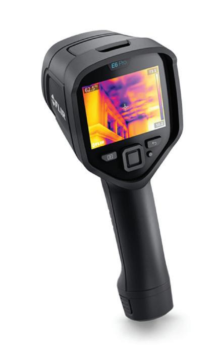
The Teledyne FLIR E6 Pro is a rugged pointand-shoot thermal camera designed to help inspect, locate, and diagnose automotive problems quickly using 240 by 180 thermal resolution (43,200 pixels) and vibrant thermal imagery supported by FLIR-patented MSX (multi-spectral dynamic imaging). Featuring a 3.5”, 640 by 480 resolution touchscreen, the E6 Pro allows users to edit and organize photos, add detailed notes, and upload files directly from the camera to the FLIR Ignite cloud for convenient access from any device. Users can also share images with customers and create quick reports directly in FLIR Ignite or create advanced reports in FLIR Thermal Studio.
For more information, visit
VehicleServicePros.com/53073052

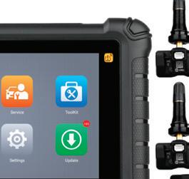

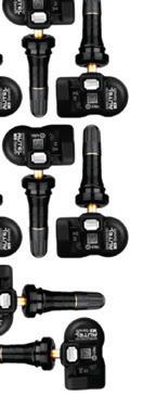
The Autel MaxiTPMS TS900K8 Kit includes the MaxiTPMS TS900 tablet and eight 1-Sensors. The Androidbased tablet offers TPMS, diagnostics, and service functions, including sensor activation, relearning, and programming. It is compatible with Tesla OE and Autel BLE sensors. The TS900 provides advanced diagnostics, preand post-scans, and supports over 40 service functions. The 1-Sensor is a universal, programmable TPMS sensor with dual frequency and interchangeable valve stems.
For more information, visit VehicleServicePros.com/55320183
For more information, visit VehicleServicePros.com/55301437
The Mac Tools Automotive and Motorsports Scan Tool, No. ET4200, features a rugged 7” body and seamless wireless connection to the VCI. The ET4200 is equipped with the BSCAR VII diagnostic connector that supports cutting-edge protocols like CANFD and extended DoIP. It allows users to perform a wide range of functions, including reading and clearing DTCs, data stream analysis, actuation tests, coding, matching, service lamp reset, brake pad reset, and more. Intelligent VIN identification provides swift diagnostics. The kit includes motorcycle connectors and other essential accessories. Battery tester and video scope expansion modules can be added for more utility.
For more information, visit VehicleServicePros.com/55276617


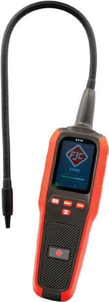
The FJC Electronic Leak Detector, No. 5110 , is designed to detect all CFC, HFC, HCFC, and HFO refrigerants, including R-134a and R-1234yf. It features automatic calibration, a mechanical pump, three sensitivity levels, and a low-battery indicator. Includes four AA batteries. Compliant with SAE J2791, SAE J1627, and EN14624 standards.
For more information, visit VehicleServicePros.com/55320620
Innova Electronics Corporation has introduced the tant , a new addition to the company’s Smart Diagnostic series. The SD39 is currently available at AutoZone, with additional parts retailers expected to carry it later this year. The tool is designed for advanced DIYers, technicians, mobile mechanics, and fleet service providers who want diagnostic capabilities in a compact format without moving to a tablet platform. It provides all-system diagnostics, reset functions, active tests, and integration with the RepairSolutions2 (RS2) app. Through RS2 compatibility, users can access diagnostic data, vehicle-specific fix recommendations, and repair guidance.

For more information, visit VehicleServicePros.com/55312719
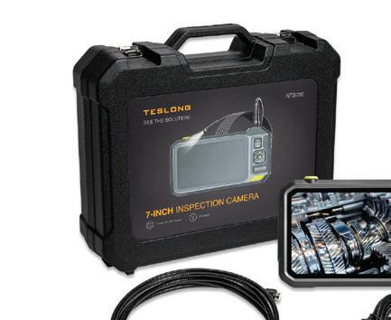


The Teslong NTS700 Pro Inspection Camera features a 7” 720p HD IPS color display, offering crisp visuals that allow the user to easily identify issues in cylinder heads, exhaust systems, wiring systems, and other tight spaces. The screen’s IPS technology ensures accurate colors and wide viewing angles. With a 6000mAh rechargeable lithium battery, the user can perform extended jobs without frequent recharging. The camera probes are all IP67 waterproof and dust resistant. For added versatility, users can select a probe with either a dual or triple lens to experience split-screen capability, enabling them to view multiple camera angles at once. Additional features include Wi-Fi streaming capabilities and a flexible design.
For more information, visit VehicleServicePros.com/55272138
The Snap-on TRITON features a wireless connection, a sleek, streamlined design, rugged grip handles, and a lightweight body. Fast-Track troubleshooting allows users to see how other technicians have tackled the same problems. Smart Data automatically selects the PIDs related to the code that the technician is working on and flags which ones are out of range. Prefiltered functional tests and technical service bulletins help confirm the right path to repair. Guided component tests and a 2-channel scope help users confirm the fix. Its 10” capacitive color touchscreen display provides improved readability and superior visibility. With fast boot-up and one-touch code scan and clear, users can work more quickly through repairs.
For more information, visit VehicleServicePros.com/55291236


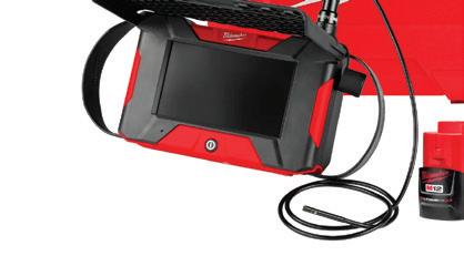


The Milwaukee Tool M12 Auto Shop Borescope with Wi-Fi File Sharing is optimized for the automotive shop, delivering simplified inspections and faster repair approval. Users can quickly share and document findings from the 5.5” HD touchscreen display, as well as add context to photos and videos through onboard drawing, audio, text, and video trimming features. Once connected to the shop’s Wi-Fi, it can quickly share and document findings via email for faster repair approval.
For more information, visit VehicleServicePros.com/55301530


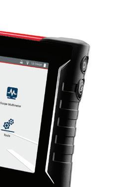
The Maximus Pro from Matco Tools is a mid-level scan tool designed for automotive technicians. It features fully-unlocked software capabilities, technicians can service all makes and models without additional purchases. Its innovative user interface ensures easy navigation for quick diagnostics, says Matco, while the latest Android 15 powers enhanced speed and performance. Featuring a large screen, the Max Pro is IP-65 rated for durability against dust and water and is built to withstand tough shop environments. With the MaxSync VCI and MaxFix included, users have the tools they need to maximize their diagnostic capabilities.
For more information, visit VehicleServicePros.com/55283010


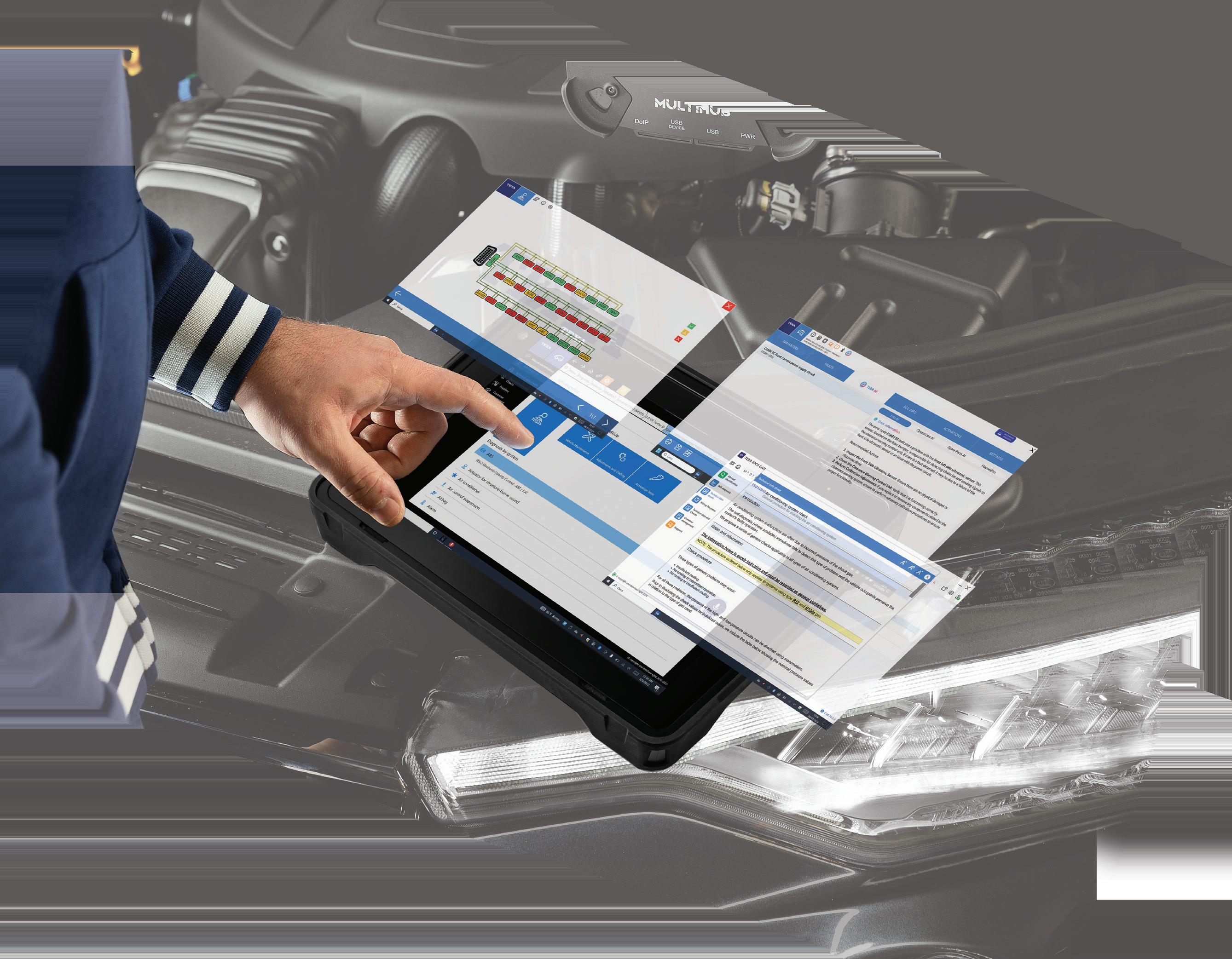
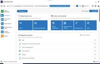
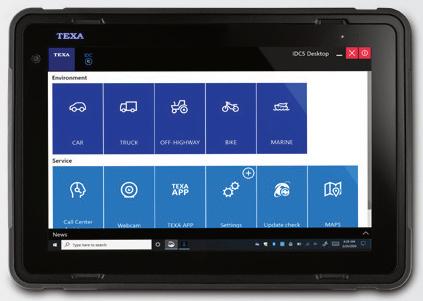
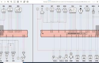
The IDC6 HD Truck Diagnostics - AI Diagnostic Assist from TEXA USA features redesigned navigation and a new homepage layout that simplifies options and adapts to user habits with tooltip messages recommending ideal functions and highlighting frequently used selections and options. It includes an AI-supported Diagnostic Assistant that provides guided repair experience features. It also offers the AI Global Search function and AI Smart Diagnosis function to provide technicians with the advanced experience and troubleshooting knowledge to quickly and accurately diagnose repairs.
For more information, visit VehicleServicePros.com/55277362
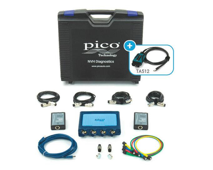
The PicoScope NVH Essentials Standard Kit from Pico Technology is a comprehensive package for testing and diagnosing the noise, vibration, and harshness of a vehicle. The kit is powered by the PicoScope 4425A and allows measurement on 3 axes with the option to measure vibration or sound on a single axis at an additional vehicle location. The addition of the Mongoose-Plus ISO/CAN 3 J2534 Lead (TA512) allows users to acquire engine and road speed signals.
For more information, visit VehicleServicePros.com/55300929
The OPUS IVS DrivePro 2 Plus is designed to be a diagnostic platform that the company says offers 100 percent brand coverage. Users can access their own OE software through MyCarDAQ or pre-existing OE applications through the tool’s Farsight mode, and the device supports advanced J2534 applications. The DrivePro 2 Plus allows users to access direct communication with brand-specific master technicians as well as integrated AI for instant repair suggestions and troubleshooting. It features up to 16GB of RAM, an Intel Core i3 or i5 processor, and is 5G capable. It comes in a rugged, drop-tested body with a 13” Gorilla Glass touchscreen.
For more information, visit VehicleServicePros.com/55242483


1-YEAR FREE