

Digital thread vs. unified namespace
Replace rigid architectures and point-to-point integrations with scalable framework for solving data integration challenges


Automation starts with precision. We deliver the measurement technology.


Everything is possible. With VEGA.


Industry 4.0 sets high standards for the future of sustainable production. Our level and pressure instrumentation is designed to meet these demands, combining the essential features that enhance quality, efficiency, and flexibility in your processes –every single day.
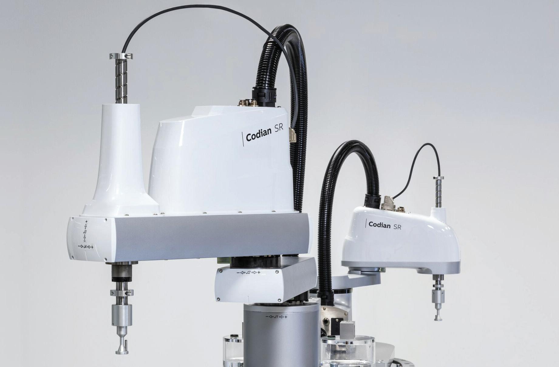
New Codian SR
Plug-and-play
SCARA robot
With the new Codian SR, B&R adds SCARA kinematics to its Codian portfolio of open robot mechanics and integrated Machine-Centric Robotics solutions. The new series offers high-speed articulated movement with four degrees of freedom –perfect for tasks like pick-and-place, loading and unloading, assembly and dispensing that demand both speed and repeatability on a compact footprint.
New SCARA models allow easy, compact mounting, even in cleanrooms
Open robot mechanics offer full design flexibility for third-party integration
Optional machine control integration ensures seamless engineering and synchronization
br-automation.com


cover story
Digital thread vs. unified namespace
Replace rigid architectures and point-to-point integrations with scalable framework for solving data integration challenges
Anna Townshend, managing editor
machine input
Beyond fixed hardware: SDA adapts How software-defined automation is converging IT/OT and empowering edge intelligence
Mike Bacidore, editor in chief
plc security
OT security moves in lockstep with control
How beneficial are real-time security, AI-based protection and device visibility?
Tobey Strauch, contributing editor
machine vision 7 keys to integration for in-line metrology
Beyond go/no-go: Solving the measurement puzzle at production speed
David L. Dechow, engineer, programmer and technologist
product roundup Blocks and buses for data and safety
Backplanes and terminals enable communications


Need your variable speed drive to have an easy and problem-free connection to your favorite Ethernet or Fieldbus network? Yaskawa takes your desire for control and data seriously.
Our new GA800 is no exception. It provides data-rich connectivity with all major industrial networks. The Industrial “Internet of Things” is here. Let Yaskawa help satisfy your appetite for it.

Your days are complicated enough. Let us help simplify them. Call Yaskawa today at 1-800-927-5292.


CEO
Endeavor Business Media, LLC
30 Burton Hills Blvd, Ste. 185, Nashville, TN 37215
800-547-7377
Chris Ferrell
COO
Patrick Rains
CRO
Paul Andrews
CDO
Jacquie Niemiec
CALO
Tracy Kane
CMO
Amanda Landsaw
EVP, Design & Engineering Group
Tracy Smith
Group Content Director - Processing, Engineering Design & Automation
Keith Larson
editorial team
editor in chief
Mike Bacidore mbacidore@endeavorb2b.com
managing editor
Anna Townshend atownshend@endeavorb2b.com
digital editor
Madison Ratcliff mratcliff@endeavorb2b.com
contributing editor
Rick Rice
rcrice.us@gmail.com
contributing editor
Joey Stubbs
contributing editor
Tobey Strauch tobeylstrauch@gmail.com
contributing editor
Charles Palmer charles101143@gmail.com
columnist Jeremy Pollard jpollard@tsuonline.com
design/production
production manager
Rita Fitzgerald
rfitzgerald@endeavorb2b.com ad services manager
Jennifer George
jgeorge@endeavorb2b.com art director
Derek Chamberlain
subscriptions
Local: 847-559-7598 • Toll free: 877-382-9187
email: ControlDesign@omeda.com
sales team
Account Manager
Greg Zamin gzamin@endeavorb2b.com
704/256-5433 Fax: 704/256-5434
Account Manager
Jeff Mylin jmylin@endeavorb2b.com
847/516-5879 Fax: 630/625-1124
COLUMNS


Mike Bacidore editor in chief mbacidore@endeavorb2b.com
Digital transformation requires partners
DIGITALIZATION HAS BEEN the talk of the Control System Integrators Association (CSIA) for several years. In 2023, GE Digital’s Tim Ogden led a panel discussion with Patti Engineering’s Sam Hoff, Triad Control Systems’ Nigel James, GreyLogix Brasil founder/CEO Renato Leal and Rain Engineering’s Don Rahrig about digital transformation during the CSIA Conference. In 2024, Dr. Brian Romano, director of technology development at Arthur G. Russell (AGR), and an ISA fellow, joined Hoff, Leal and Ogden for a panel-discussion update. This year, Titus Crabb, president, Vertech Industrial Systems, and Jim Gillespie, co-founder and chief growth officer at GrayMatter, joined Romano and Leal on a panel moderated by George Young, vice president, global digital and cybersecurity services, Rockwell Automation, to discuss real-world experiences with digital transformation.
such a rapid pace. Digital transformation is not a miracle, and that’s where people get a bitter taste in their mouth. It can’t possibly deliver if there’s no organizational change management that goes with it.”
Crabb recalled partnering with a consultant that did lean consulting for a brewery. “In the end, this brewery was facing a decision to expand, even though they were landlocked, and facing a multimillion-dollar capital project at another brewery,” he noted. “It turned out they didn’t need to expand.” The brewery was able to rearrange its plant and double production without expanding.
Undertaking digital projects takes a bit of courage, a lot of practical knowledge and a solid relationship.
Undertaking digital projects takes a bit of courage, a lot of practical knowledge and a solid relationship with the client. Many things can go wrong, but clear understanding enables trust. Collaboration and communication go hand in hand. “It comes down to making sure everyone is on the same page and the deliverables are defined,” said Romano. On one AGR project that began about four or five years ago, “we had to take a step back and ask how we could leverage seven of the nine pillars of Industry 4.0 and provide a program to the customer to give them a better opportunity to succeed.”
A lot depends on the customer and the customer’s progress or maturity. “Sometimes you have to say no, if they’re not ready for it,” explained Romano. “It’s important to know where your customer is.”
Vertech takes its role as technology practitioners seriously. “It’s incremental, and it’s a partnership,” said Crabb. “If you define digital transformation as using technology to improve organizations, new technologies are coming out at
Young emphasized the emotional level of the client. “The best proposal frequently loses because you don’t have the personal relationship,” he noted. “If you get the client satisfaction, you have an executive on your side for life. And you’re probably going to do a stream of projects that will be financially and personally rewarding.”
At GreyLogix Brasil, keeping a dedicated team focused on new projects is important. “We have a New Ventures team,” said Leal. “There’s an investment curve, and there’s a learning curve. This team is apart from other teams.”
The heart of any digital transformation is data. It feeds production, business decisions and the digital twin. There are four or five ways to define a digital twin, explained Romano, who suggested that an organization like CSIA has the opportunity and the ability to standardize terms like “digital transformation” and “digital twin.”
Many things can go wrong and take the wind out of the sails, cautioned Gillespie. The ideal project will have strong executive-level sponsorship. One customer wanted an airport type of display in the factory, with information visible to everyone. “It changed them from an opinion-based culture to a data-driven culture,” said Gillespie.

Jeremy Pollard jpollard@tsuonline.com

Step-by-step commissioning with PLCs
COMMISSIONING A STAND-ALONE machine project based on control with a programmable logic controller (PLC) and a human-machine interface (HMI) has many facets to the successful implementation of the equipment. There is a responsibility by the design and fabrication team to test the system, per the customer design. Once the machine has been put through its paces, it’s ready for shipping. Customer visits will vet the operation to make sure that it meets their specifications. To get there, commissioning tests and steps need to be followed.
There is a control panel with the power components installed such as relays, starters, and/or VFDs. There may be a line filter, control transformers and an uninterruptible power supply (UPS). Device fusing would be present.
state can then be identified to be sure the correct polarity of the sensor has been wired. Each input state change is then recorded to document the procedure.
VFD control can be done manually to check the system for rotation and speed control.
While a test plan can be helpful, they are often overlooked due to the time and cost of preparing. Normal power system checks are done with the system drawings, and the physical point-to-point wiring is metered and checked off on the panel drawings. This includes all power connections to all hardware in the system. Power fusing has to be considered since installation is required before applying power. Applying system power will now allow for device power-up checks such as PLC status, VFD status and peripherals.
Most of the start-up effort will go into the interfacing with the real world. Peripheral devices will be connected with an Ethernet network in the panel. Once power has been applied, the connectivity of these devices can be checked using Internet control message protocol (ICMP) commands.
Now that the connectivity has been verified and the power and status lights have been interpreted, we have to get down to the business of the control system. Typically, the machine’s I/O would be wired to terminal blocks whose in-panel side would be wired to the I/O modules. With the PLC in program mode, inputs would be checked first.
The benefit of testing the connected inputs with power on is that, for example, a blocked photo sensor will change state, and that change can be monitored on the I/O module itself. This tests the field wiring from the sensor to the terminal blocks and then to the I/O module directly. The rest
This also checks for correct power supply wiring, which, in dc circuits—NPN/PNP devices—can prove very helpful. Checking outputs is a bit trickier due to machine motion. It is advisable to check outputs using the force function in the PLC system to energize each output and monitor the end device such as a relay or starter. The outputs will actually turn on the device to prevent motion; the motor/VFD disconnect should be turned off. Once the end device has been validated, you could then turn power on to the device to check rotation. Be sure however to remove the coupling from the motor to the end mechanics. Once rotation has been confirmed the coupling can be put back on.
VFD control can be done manually to check the system for rotation and speed control.
The last piece of the puzzle is the system evaluation using the designed software component. The HMI component should be checked first. Each screen would have interface components, which would need to be checked. A motorstart function from the HMI would need to be checked in the PLC program/data table directly. Data in the PLC can be manipulated to engage the output interface components such as “motor on” indicators.
The focus is now set on the control algorithms in the PLC to check sequencing, interlocking and control strategies, which allows the machine to operate as intended. The sequencing can be checked in manual to make sure each device operates as intended.
Only when the previous steps are completed successfully would the machine be ready for automatic operation. This should also test use cases for safety interruptions, sensor failure, output device failure and sequencing failure.
JEREMY POLLARD, CET, has been writing about technology and software issues for many years. Pollard has been involved in control system programming and training for more than 25 years.

Rick Rice contributing editor rcrice.us@gmail.com
Fundamentals of presence sensing
A KEY ELEMENT OF ANY control-system design is accurately determining whether an object is present. This might come in the form of sensing the position of a driven device, extended or retracted or somewhere in between, or just the simple presence of an object in a general sense, thus triggering further action.
Depending on the object being detected, a number of different methods of sensing can be used. In many cases, multiple methods can be used with comparable results.
The most common sensor classes are proximity, photo-electric, pressure, temperature, sonic or ultrasonic, motion, flow, force, load, level and position, or limit, sensors, but further classes of sensors exist. Presence sensing is the method of determining if an object is present.
The capacitive switch detects the change in capacitance caused by the presence of a nearby object. It works by creating an electrostatic field and then measuring the change in that field, which is caused by the introduction of an object to that field.
An inductive sensor, on the other hand, detects changes in an electromagnetic field when a conductive metal object is close by.
A presence or force sensor or load cell can be used to detect the presence of an object.
At the base level, the most simplified version of a sensor used to determine the presence of someone or something would be a limit or position sensor. This device uses physical contact to displace a lever to complete or break a circuit through which current is running.
For example, a lever connected to a normally closed contact with springs to keep it in position would indicate the presence of an object when the lever is acted on with enough force to displace the lever and break the contact. This would work in a similar way if the contact was normally open and displacement of that same lever would “make” the contact when an object applies force to the lever.
In reality, every presence-sensing device is a variation of the limit switch. By using some method to detect the presence or absence of an object, the internal contact of the sensor will either be made or broken. The method by which the object is sensed will vary, but the purpose of the sensing device remains the same.
One such sensing device is the proximity switch. This device, as the name suggests, counts on the close proximity of an object to make or break contact without making physical contact with the device.
There are two main types of proximity switch, inductive and capacitive. The difference has to do with the electrical characteristics of the device.
The key difference is electrostatic vs. electromagnetic. Inductive sensors are used to detect conductive objects, while capacitive sensors are used to detect non-conductive objects. Examples of each object would be a metal tab or piston for inductive and a piece of wood or cardboard or plastic for capacitive sensors.
The size of the field determines the effective sensing range of the device. Generally, capacitive sensors are limited in size because the amount of available field with which to sense is more limited than the inductive version.
Both sensors come in shielded and unshielded versions. This uses the principle that fields are generated in a mushroom shape off the effective face of the sensor. In an unshielded device, the sensing area is determined only by the size of the sensor face and, as such, can be quite large and inaccurate.
By shielding the sides of the sensor at the face, we can limit the spread of the mushroom into more of a cylinder shape. This helps in gaining more accuracy because it limits the bloom effect of the unshielded field.
However, shielding a sensor reduces the sensing range off the face of the sensor so the device must be much closer to the object being sensed. If there is any variation on the path of the object when moving, there is risk of striking the sensor with the object.
It is best, therefore, to place the sensor perpendicular to the path of the object rather than directly in the path where one might rely on the sensor to stop motion before the object strikes the sensor.
Another very popular presence sensing device is the photoelectric sensor, also referred to as a photo-eye. As the name suggests, this sensor produces and then detects
technology trends
a beam of light. There are three types of photoelectric sensors—through-beam, diffuse or proximity and retroreflective. All three types have both an emitter and collector of light source.
For a through-beam, the emitter and collector are in two separate containers while both retro-reflective and diffuse sensors have the emitter and collector in the same physical body. When an object is introduced to that path of light, the beam is interrupted, and the sensor detects the presence of the object.
The through-beam sensor is quite simple in function. In normal operation, the light emitted by one half of the pair is detected by the other half of the pair. If an object enters the path of the light in the pair, a switch in the receiving side is then triggered.
The pair can be set up to be normally closed/on when light is present or normally open/off when light is present. This sensor can be difficult to set up as the emitter and receiver must be in near-perfect alignment. This might be difficult to do, especially over longer distances between the emitter and the receiver.
The other two methods work the same way but differ in the way that the emitted light gets to the receiver. For retroreflective, the emitted light is bounced off of a reflector and back to the receiver. Since, like the through-beam, the light is being interrupted to detect an object, any object that blocks light can be detected.
For a diffuse sensor, the emitted light is bounced off of the object being detected and back to the receiver. For this reason, the object to be detected must have reflective properties. If it absorbs light, then it cannot be detected by a diffuse sensor.
Remember that the emitter and receiver are in the same physical body for both the retro-reflective and diffuse sensors, so path of the beam out and back are relatively narrow.
A third method of sensing makes up the presence sensing devices—ultrasonic. This uses some of the same principles of a light-emitting sensor, but it uses sound waves instead of a light beam. The sensor sends out high-frequency sound waves and then measures the time it takes for the sound to reflect back after striking an object. In its base form, a sonic sensor can simply indicate that sound has been reflective but, to be more accurate, the time it takes for the sound to return is used in most applications.
For example, if we are sensing an approaching object, we likely don’t want to know just that a reflected sound wave has been detected but that a particular sound wave has been detected within an expected time differential and, thus, the distance away from the sensor. Since the speed of sound in air is a known quantity, this type of sensor can lend itself well to the detection of liquids or granular products, particularly in vessels like tanks or hoppers. It can also be used to detect the approach of a car or person into a known workspace.
An interesting note on all of the sensors discussed, the packages are very similar in size and mounting methods. While the three types of sensors make up most of the presence-sensing devices, variations of these can also be used. For example, an area scanner uses the principles of a diffuse photo-eye to sense a person or object in a much larger workspace. This is done by mounting the send/receive device on a multi-axis device that moves in all directions of a defined space to create a three-dimensional scan area.
Due to the need to send and receive at much higher rates to cover the whole area effectively, the light source is usually a laser or infrared laser. Typical photosensor wavelength is in the near-infrared and visible-light spectrum, while laser operates in the ultraviolet to infrared range.
An area scanner uses a mirror to deflect the light source rather than moving the light source around. The ultra-fast vibration movement of the mirror allows for a significant area to be scanned in a very short time span.
Other sensing methods can be utilized for presence sensing. For example, a presence or force sensor or load cell can be used to detect the presence of an object. One example of this would be a safety mat that an operator would stand on while operating a press.
Presence sensing can take many forms. New technologies offer better, more accurate versions, but the basic principles remain. Of course, with most sensors these days, IO-Link is a standard offering, and this adds an extra element to a control design with value-added information available from the sensor to help with troubleshooting and data analytics.
RICK RICE is a controls engineer at Crest Foods (www.crestfoods.com), a dry-foods manufacturing and packaging company in Ashton, Illinois.

Tobey Strauch contributing editor tobeylstrauch@gmail.com
What constitutes a safe speed?
MANY TIMES, IN INDUSTRIAL AUTOMATION we hear the term “safe speed” in motion conversations. It’s important to define safe speed and how it applies to control design, in relationship to functional safety. First, let’s define a safe speed. Safety terms include safe reduced speed (SRS) and safe limited speed (SLS). SRS reduces a speed to a speed that minimizes risk of harm. This applies during situations when an operator might have to interact with moving parts. SLS is a speed that is set to a specific, predefined value. For instance, carts may be set to a specific speed for jogging in manual mode. In this instance, max speeds are reduced to match machine state.
A robot may continue as the human backs away. ISO 10218-1 shows a speed of less than 250 mm/s is usable in robotics for tool center point speeds. There are numerous studies that show 130 to 150 mm/s is less likely to cause harm. Newton’s Law would tell us that higher speeds cause more harm, so apply some sense to physics. An apple falling on your head does not have the same harm factor as a bowling ball falling on your head.
What if an operator needs to back out of startup? At a reduced speed, it may be a quicker stop.
ISO 12100: This standard addresses machine speeds and is a guide for setting up machine design requirements for reducing risks based on understanding machine speeds and functional safety.
ISO 13849: This standard provides guidelines for the design and implementation of safety-related parts of control systems. It includes requirements for safe speed functions to ensure machinery operates within safe limits.
IEC 62061: This standard focuses on the functional safety of electrical, electronic and programmable electronic control systems. It outlines the necessary measures to achieve safe speed and other safety functions.
OSHA regulations: The Occupational Safety and Health Administration (OSHA) provides guidelines for safe operation speeds, emphasizing that machinery should be operated at speeds that allow it to stop safely under all conditions.
How does this relate to machine controls? Controls engineers must use sensors to show states or state changes.
Let’s look at some examples. If a person must load trays in a robot area, as soon as the gate opens, or a person passes into the space where the robot is moving, then code can acknowledge that a human is in the zone. If a human is in the zone, and the robot is moving, then it will automatically be given a reduced speed for the purpose of acknowledging the interaction. Then, once it finishes its move, it can be set to pause or stop so that the next step is not completed until the human clears.
Safety devices today allow robot zones, whereas the closer the human gets to the robot, the robot slows and eventually stops. Safe stops can also be categorized. Safe operating stops are different than safe torque offs, but there is still an expectation that the motor control does not deviate within a range. Safe stop is something to consider with safe speed regulation, as speeding and stopping are related, but in this case the focus is on speeds.
Reduced speeds are not just applicable in robot scenarios. Reduced speeds could be used in staged startup sequences, as well. Why? What if an operator needs to back out of startup? At a reduced speed, it may be a quicker stop than at a max speed.
Limiting the machine speeds per states allows reduced risk. A startup condition can have a range of idle to normal speed. A normal automatic condition may have a range from low speed to high speed.
If a machine has a cart that loads equipment and will have people walking in the area, the speed must be less than walking speed. This is a different regulation, which is ISO 12100. The related regulation is ISO 13849, which sets requirements for safety-related parameters.
The idea of ISO 12100 is that the control system defines changes in speed based on risk. Using parameters such as range, speed, acceleration, deceleration and load capacity in relationship to machine state can allow the speed references used to deter any uncontrolled speed change.
Tobey Strauch is an independent principal industrial controls engineer.
Charles Palmer contributing editor

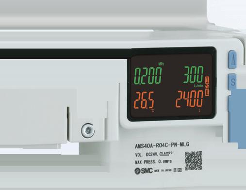
How industrial panel displays are changing
INDUSTRIAL PANEL DISPLAYS have undergone significant advancements in recent years, driven by the growing demand for better performance, durability and functionality. These innovations have not only improved user interaction but also enhanced efficiency, safety and adaptability across industrial environments.
Industrial panel displays feature higher resolutions, such as full HD (1920x1080) and 4K (3840x2160), providing crisp and clear visuals. High resolution is particularly beneficial for applications requiring detailed monitoring, such as precision manufacturing, control rooms and medical equipment.
Touchscreen interfaces have become a standard in industrial panel displays, offering intuitive and user-friendly interaction.
These connectivity advancements facilitate real-time data sharing and remote monitoring, aligning with the needs of smart factories and Industry 4.0.
Integrating edge computing capabilities into industrial panel displays allows for data processing directly at the source. This reduces latency, enhances security and enables real-time analytics. Edge-enabled displays are particularly useful in applications such as quality control, where instant data processing is critical.
Environments often expose equipment to extreme temperatures, vibrations, dust and moisture.
Projected capacitive touch offers multi-touch capability, high durability and excellent resistance to environmental contaminants such as dust, oil and moisture. Resistive touch screens are enhanced with improved durability and responsiveness for environments where gloves are commonly used.
These technologies ensure seamless operation even in harsh industrial conditions, improving productivity and user experience.
Industrial environments often expose equipment to extreme temperatures, vibrations, dust and moisture. The latest panel displays are built with rugged designs. IP-rated enclosures protect against dust and water, with ratings such as IP65 and IP67. Wide operating temperature range displays are capable of functioning between -30 °C to 85 °C. Shock and vibration resistance ensures durability in heavy-duty applications such as mining and construction.
These features make industrial panel displays reliable in challenging conditions, reducing downtime and maintenance costs.
Industrial panel displays now support a wide range of connectivity options. Ethernet and Wi-Fi provide seamless integration into Industrial IoT (IIoT) networks. USB and HDMI ports simplify connections with other devices. Fieldbus protocols, including Modbus, CANbus, and Profinet, enable communication with industrial controllers and sensors.
Artificial intelligence (AI) and machine learning (ML) are being incorporated into industrial panel displays to enhance automation and decisionmaking. These features allow displays to adapt interfaces based on user behavior, provide predictive insights and alerts for potential equipment failures and enable intelligent data visualization, highlighting critical metrics.
Such innovations help operators make informed decisions, improving efficiency and safety.
Energy-efficient industrial displays are becoming a priority due to environmental concerns and cost considerations. Low-power LEDs reduce energy consumption without compromising brightness. Dynamic brightness control automatically adjusts brightness based on ambient light conditions, saving energy. Power management features include sleep modes and advanced power control settings.
These advancements contribute to reduced operational costs and support sustainability goals.
Cutting-edge display technologies have been integrated into industrial panels to enhance performance. OLED displays provide superior contrast, vibrant colors and wider viewing angles compared to traditional LCDs. E-ink displays are ideal for applications requiring low power and sunlight readability, such as outdoor kiosks. Micro-LED technology offers high brightness and energy efficiency.
Charles Palmer is a process control specialist and lecturer at Charles Palmer Consulting (CPC). Contact him at charles101143@gmail.com.
Beyond fixed hardware: SDA adapts
How software-defined automation is converging IT/OT and empowering edge intelligence
by Mike Bacidore, editor in chief
SOFTWARE-DEFINED AUTOMATION (SDA) is changing machine components. Two industry experts explain the how and the why behind the shift.
Rares Curatu is industrial automation & machinery industry manager at MathWorks.
Sean Saul is the vice president of product at Emerson’s process systems and solutions business, where he is responsible for leading the overall product direction for the DeltaV distributed control system and safety instrumented system platforms.
Since joining Emerson in 2012, Saul has held multiple leadership roles across sales, marketing and strategy functions. He holds a bachelor’s degree in electrical engineering from the University of Texas at Dallas and a master’s degree in business administration from the University of Texas at Austin.
What is the primary focus of SDA?

Rares Curatu, industrial automation & machinery industry, MathWorks : Software-defined automation (SDA) increases industrial automation systems’ flexibility, adaptability and intelligence, as described by concepts such as flexible manufacturing, autonomous automation and Industry 4.0. By decoupling automation logic from task-specific, fixed-configuration hardware, SDA allows production processes and workflows to be updated in software, with minimal manual intervention to reconfigure the manufacturing line. This enables rapid response to changing requirements, reduces downtime and improves traceability and production quality.

Sean Saul, vice president of product, process systems and solutions business, Emerson : As companies’ operating philosophies shift toward more flexible manufacturing, they need improved technology options so they can continually reconfigure and innovate to meet market demands. The traditional controls engineering methodology of “design once, build once, run forever” is no longer
sustainable. Software-defined automation is designed to provide users more flexibility than traditional control technologies by abstracting software applications from specific hardware platforms, delivering productivity and reduced costs throughout the lifecycle of a facility.
As an example, software-defined control allows flexibility for where control workloads run, as systems are no longer tied to specific hardware configurations. With potentially more compute resources, control can move beyond existing function blocks—it could be running more sophisticated AI/ ML techniques directly on the same hardware as the PIDs.
What are the primary benefits of softwaredefined automation?
Sean Saul, vice president of product, process systems and solutions business, Emerson : Software-defined automation is more flexible— running on a wider variety of hardware platforms and allowing more compute power at the edge than ever before. It is also incredibly adaptive, with effortless scalability as components are added or upgraded in a virtual environment. Each of these factors contributes to higher productivity and lower costs across the lifecycle of manufacturing facilities.
Rares Curatu, industrial automation & machinery industry, MathWorks : SDA creates the opportunity for machine builders to innovate, differentiate and deliver long-term value. SDA systems stand out ahead of “conventional” automaton systems.
SDA expands functionality with advanced features such as predictive maintenance, data analytics, anomaly detection, virtual sensors and high-precision control. For example, Coca-Cola developed a virtual pressure sensor with machine learning to improve beverage dispenser diagnostics.
It creates new business models: The software-centric approach supports value-added services like remote diagnostics, continuous software updates and data-driven
machine input
maintenance contracts. For example, Aerzen Digital Systems used anomaly detection with server-based AI solutions to deploy models rapidly in a DevOps pipeline.
Better machines improve overall equipment effectiveness (OEE). Intelligent automation increases uptime, throughput and product quality by reducing manual interventions and enabling real-time optimization. For example, DHGE and DMG MORI developed AI applications for predicting machine tool failure risks.
SDA brings greater system functionality and more opportunities for machine builders to build better products and differentiate through software, features, services and quality.
How does software-defined automation figure in the convergence of IT and OT?
Rares Curatu, industrial automation & machinery industry, MathWorks : SDA solution architectures can involve edge and cloud components, bringing IT and OT systems closer together. On the factory floor, high-performance industrial controllers run advanced algorithms and connect machines to plant and enterprise networks, blurring traditional IT/OT boundaries.
SDA solution architectures, high data volumes and high volumes and complexity of software demand an evolution of how systems and software are developed. SDA software-development practices are more similar to IT development practices than to traditional OT. Some of the changes include advanced analytics and AI, continuous improvement, digital twins and cybersecurity.
More measurement data creates an opportunity for data analytics and AI features. Latency-sensitive or real-time features are implemented on the edge, on industrial controllers. Algorithms that are not timing-critical can execute away from the factory floor, often using data features extracted on the edge.
If certain values, such as the temperature inside a motor, are hard to measure, AI with physics-based models can be used to develop virtual sensors that use a system model and other measurement data to infer a virtual sensor measurement.
If measurement data—for example, fault data or edge scenario data—is limited, physics-based models can be reused for generating synthetic data. This data can be used to train AI models. For example, Mondi implemented statisticsbased health monitoring and predictive maintenance for manufacturing processes with machine learning.
SDA systems don’t have to age the same way as traditional automation systems. Their flexibility and connectivity create the opportunity to develop perpetually upgradable machines.
Engineers perform model-in-theloop, software-in-the-loop and hardware-in-the-loop tests to prototype, test and validate their designs before ever deploying code in production. Together with continuous integration/continuous deployment (CI/CD) programming practices, engineers can perform software updates that are well-tested and validated, addressing customer feedback and evolving requirements, to systems that are already in the field. For example, Krones built a reinforcement learning–based process control system that can be updated with AI models that are retrained remotely.
The data-rich SDA systems create an opportunity to deploy and operationalize digital twins. SDA often involves high, bi-directional data flow that can offer operators insights into processes. Reusing the models used for system development, machine builders can build live digital twins for real-time monitoring and optimization. For example, Atlas Copco minimizes cost of ownership using simulation and digital twins.
While not a new requirement for automation systems, SDA’s softwarerich and connected nature raises the bar for cybersecurity measures. Besides securing controllers and following network security best practices, cybersecurity must be built into the control software. For instance, robust control systems must detect and mitigate abnormal behavior and avoid chain reactions. This is an overview of how to deal with cybersecurity challenges in embedded system designs.
SDA brings IT and OT closer together, creating opportunities but also challenges and changes to how systems are engineered and software is developed. With the right tools and workflows, IT-like software development practices can be integrated into machine builders’ workflows and play a crucial role in developing the next generation of manufacturing equipment and machinery.
Sean Saul, vice president of product, process systems and solutions business, Emerson : Software-defined automation will accelerate the trend of IT/OT convergence as the clear lines that currently define responsibilities, often set by the Purdue Model, continue to blur. Many of our customers currently have
manufacturing technology organizations combining the skillsets of IT and OT experts to achieve objectives that often compete: scale and efficiency (IT) vs. availability and resilience (OT). The promise of software-defined automation is these objectives will no longer trade off against each other, driven by a common technology foundation designed with the resilience that mission-critical production applications demand.
Which components will see the biggest impact from software-defined automation?
Sean Saul, vice president of product, process systems and solutions business, Emerson : Edge devices, industrial PCs and controllers will all benefit from a more software-defined approach. The demand for more compute power at the edge is key to the coming wave of AI technologies that will create a paradigm shift in manufacturing. There is no denying that AI technology will create many new opportunities for innovation, but the latest workloads cannot be run on legacy control hardware, nor can they be deployed exclusively in a cloud environment. Software-defined controllers and edge devices will bring the necessary compute power closest to the underlying manufacturing process, unlocking the ability to drive competitive advantage in an increasingly complex and competitive global marketplace.
Rares Curatu, industrial automation & machinery industry, MathWorks : Significant impact of SDA is being seen in controllers,
including programmable logic controllers (PLCs), programmable automation controllers (PACs), industrial PCs (IPCs) and drives, components where advanced algorithms and software-driven features are increasingly integrated.
There is a growing trend toward the use of virtual PLCs, which are moving some edge functionality to the cloud. Among other benefits, using virtual PLCs allows factory managers to manage PLCs closer to how they manage IT assets, rather than OT assets. However, it is unlikely that all PLC functions will soon be moved to the cloud or away from the factory floor.
For the foreseeable future, highspeed, real-time and deterministic
control algorithms will still be close to the factory floor on continuously higher-performance PLCs or even embedded on microcontrollers or fieldprogrammable gate arrays (FPGAs) in the machines, gradually designing out traditional PLCs.
In what ways does softwaredefined automation allow machine builders more flexibility in hardware selection and management?
Rares Curatu, industrial automation & machinery industry, MathWorks : Simulation is a key enabler of flexibility in SDA. Engineers build physics-based machine models


to size components and optimize the bill of materials before hardware commitment. The machine models are also used to test and prototype control algorithms in simulation. This reduces the need for physical prototypes and ensures designs meet performance and cost targets.
Simulation also benefits other roles, such as sales teams. Sales and pre-sales teams can use existing models to quickly evaluate configurations and demonstrate performance to customers, supporting tailored solutions and faster decisions.
With model-based design, algorithms are designed, tested and validated in simulation, using the machines’ physicsbased models. The next step is deploying algorithms on controllers. Automatic code generation enables engineers to generate IEC 61131-3 or C/C++ code directly from simulation models and algorithms. This keeps intellectual property independent of specific PLC integrated development environments (IDEs) and provides flexibility in control hardware selection. This streamlines deployment and ensures code equivalency and consistency between simulation and real-world operation.
Simulation and code generation support machine builders from engineering to sales and deployment, empowering them to optimize designs, better serve customers and decouple their solutions from specific control hardware platforms. For example, Atlas Copco minimizes the cost of ownership using simulation and digital twins.
Sean Saul, vice president of product, process systems and solutions business, Emerson : Software-defined automation allows machine builders more options to specify the right hardware for the application. It will be easier to ensure hardware is in the right price range, with the right amount of ruggedness and the right capacity, small or large, with more flexible architecture.
How can machine builders prepare for and leverage software-defined automation?
Rares Curatu, industrial automation & machinery industry, MathWorks: As software complexity grows, machine builders adopt model-based design. Model-based design puts models at the center of the engineering and development process. Engineers simulate the machinery, most often using physics-based models. With the help of the machinery models and simulation, engineers develop algorithms, such as control algorithms. In simulation, they
can iterate the design; test and validate algorithms; and perform virtual commissioning.
Automatic code generation, such as IEC 61131-3 languages or C/C++, helps deploy validated algorithms directly to industrial controllers, decoupling software IP from specific PLCs and IDEs and supporting hardware flexibility.
Model-based design can shorten development cycles and reduce development time by 50% or more. For instance, Shibaura Mechatronics, when developing a new control algorithm, has reduced the time it took engineers to adjust parameters from half a day to 10 seconds.
With model-based design, teams can try out new ideas, explore the design-space and validate concepts faster; shorten development cycles, reduce the need for physical prototypes and reduce time-to-market; maintain a digital thread for traceability from requirements to implementation and test; enable agile, iterative development for higherquality, feature-rich software; decouple the solution from specific control platforms or IDEs; reuse models as digital twins, for AI, analytics, anomaly detection and optimization; design resilient algorithms, for example, by simulating cyber attacks, as part of cybersecurity measures.
Model-based design, including code generation for industrial controllers, provides a robust foundation for managing complexity, accelerating innovation and delivering reliable, high-performance software-defined automation solutions.
With the right tools and development workflows, machine builders can capitalize on these opportunities without completely re-skilling their existing design and engineering departments.
How does software-defined automation build on existing IT and network infrastructure in factories and plants?
Sean Saul, vice president of product, process systems and solutions business, Emerson : With the best modern software-defined controllers, teams can integrate new control capacity in among their existing control technologies that are already there, leveraging the same tools and interfaces for both their software-defined controllers and the legacy controllers. This eliminates the need to rip and replace existing architecture to gain the benefits of new technologies. Teams can leave the legacy control technologies that work in place and use them in parallel, seamlessly, with their new controllers.
machine input
Tell us about your company’s product that involves software-defined automation.
Sean Saul, vice president of product, process systems and solutions business, Emerson : Emerson is developing a flexible, high-capacity software-defined controller designed for online, mission-critical operations. By deploying control workloads within a server-based environment, this new controller will simplify engineering, maintenance and upgrades while significantly reducing footprint and increasing scalability.
With twice the control capacity of a traditional controller, a single pair of servers can handle the control requirements of most large-scale facilities. The new software-defined controller will provide even more flexibility across the DeltaV system allowing control workloads to be distributed across traditional controllers and controllers hosted in a serverbased environment, all seamlessly managed by the same tools our customers utilize today.

In demanding OEM applications, precision and compact design matter. Our hollow shaft encoders are engineered for highperformance systems and are available in a wide range of sizes, delivering unmatched accuracy and long-term reliability. Every project is different. That is why our encoders are built-to-order to meet your exact specifications, with a quick turnaround to keep your project moving.
Key features:
Wide range of bore sizes: 2.5-140 mm (1/10"-5.0")
Incremental and absolute encoder options
Custom designs tailored to your application
Wide interface compatibility, including


Replace rigid architectures and point-to-point integrations with scalable framework for solving data integration challenges

UNIFIED NAMESPACE (UNS) has the potential to solve many problems for industry. Where digital transformations have been slow and siloed, UNS holds power in scalability and plug-and-play integration with an overall simpli ed architecture. With a centralized data hub and a single source of truth across all machines and processes, UNS can untangle rigid infrastructure and help solve the long-standing challenges around data and system interoperability.
No more digital thread: UNS provides centralized communication
“UNS is the single source of truth for data events in a business,” says Jacob Clodfelter, solutions architect at Flexware Innovation. “UNS is not a technology but an architecture. UNS is primarily a single data backplane for all data transactions in a business.”
UNS solves a problem with traditional industrial architecture and the “digital thread” philosophy, Clodfelter says. The digital thread in industrial automation is the idea of creating a continuous ow of digital data across the entire manufacturing process lifecycle, from design to production to service. Sounds great, right? But it doesn’t always translate so well in industry, where systems can be dynamic, parallel and even messy. Those dynamic environments aren’t really a thread or a single, linear ow of data either, and oversimpli cation can lead to rigid architectures. Industrial data moves in all directions, not along one thread, and the digital-thread concept also struggles with realtime and event-driven data, which is core to optimizing machine data system-wide.
“By having a single intermediary data backplane, the number of integrations can be reduced exponentially in a system,” Clodfelter says. “Speci cally, the math is (n-1) 2 connections via digital thread to n connections with uni ed namespace.”
Traditional architectures chasing the digital thread need a direct integration for

each application to connect to another one. “This means that any system will have integrations between all applications directly. By instead using UNS, applications communicate via a centralized service, meaning all applications only have one connection, to the central service,” Clodfelter says. This is incredibly powerful, he says, for reducing integration cost and labor in industrial automation.
“It also has advantages in security and network efciency. As the number of connected devices increases rapidly, these architectures will be critical to ef ciency, scalability, cost and reliability,” Clodfelter says.
by Anna Townshend, contributing editor

With UNS, data no longer travels from point to point. “A centralized data architecture acts as a central hub,” says Luciano Tarabocchia, presales solutions consultant at Mitsubishi Electric Iconics Digital Solutions. More traditional supervisory control and data acquisition (SCADA), manufacturing execution system (MES), enterprise resource planning (ERP) or other industrial architectures are often siloed or organized by hierarchy.
“When looking at a small system, the traditional setting may work fine, but, once you start growing the digital ecosystem throughout the
organization, there are going to be many different owners of assets and the data that comes from them,” says Tarabocchia. “A UNS architecture enables these different owners to publish their data models to a centralized space and access the various other data models that are published from other areas of the ecosystem to unify all layers of the business.” A UNS architecture essentially allows SCADA or MES assets to access real-time data from each other “without the concerns of duplication and inconsistencies,” he adds.
Why is UNS often used with Sparkplug and MQTT?
Sparkplug and message queuing telemetry transport (MQTT) are often used to build a UNS, with MQTT serving as the communication protocol and Sparkplug as the format or language that carries the payload specification or data. If MQTT is the delivery truck, the payload or data is the box of goods, and the payload specification is the packing list and labeling, explaining what’s in the box, how much is in there and what to do with it. UNS doesn’t have to be used with MQTT and Sparkplug, but the three are well-suited to work together.
“If you use UNS on top of plain MQTT, you will bump into what I call the fundamental problem of MQTT, which is: what’s great about MQTT is that you can publish anything, any data on any topic. And then what’s bad about MQTT is that you can publish any data on any topic,” says Frédéric Desbiens, senior manager of embedded and IoT at Eclipse Foundation. “You have no idea in advance what the payroll format will be or what the topic structure would be.”
Instead, the way in which Sparkplug is structured means that the topic structure is not fixed, and it’s customizable up to a point yet still predictable, Desbiens says. “Sparkplug provides a generic payload format that can express any arbitrary set of metrics. Sparkplug clients in a system or Sparkplug ap -
plications or edge nodes will be able to encode and decode that format, and then it’s up to them to figure out what the metrics mean in a specific industrial context.” In general, this provides flexibility.
“You publish not only data, but metadata about what’s in there and what units of measurement are used, or any arbitrary metadata that you need in order to contextualize that data,” Desbiens says. “That’s really the important notion about Sparkplug. This is not just about publishing metrics, but publishing metrics in a structured way and with all the information that you need to make sense of that data.”
Sparkplug also adds other benefits on top of the namespace, like stateful session management, so you don’t need to poll devices to know whether they are online. Sparkplug issues a birth certificate when a device connects to the system and a death certificate when it disconnects. “You save a lot of useless polling in your architecture because of that,” he adds.
Eclipse Foundation was created in 2004 and serves as a vendor-neutral nonprofit steward of open-source projects. “We are a code-first organization,” Desbiens says. “What we do at the Eclipse Foundation is really to provide this vendor-neutral level playing field where everyone can come and essentially collaborate around what are essentially commodities, and then this gives them resources and the time that they need in order to compete meaningfully in the commercial space,” Desbiens says.
Eclipse Foundation supports more than 425 different open-source projects around software collaboration and innovation, and Sparkplug is included among those projects. “We own the Sparkplug logo on behalf of the community to ensure that no one runs with it and closes it from an opensource perspective,” Desbiens says.
You may see Sparkplug or Sparkplug B, and, as Desbiens explains, the “B” refers to the current payload format. The original Sparkplug version had a short-lived A version, but it was updated a few months later. “It was modified to version B because there were weaknesses identified by end users,” Desbiens says, and most use Sparkplug and Sparkplug B interchangeably now. He also notes that, eventually, Sparkplug will be upgraded to version C, which members are working on now.
Will a formal UNS standard or guidelines solve the industry challenges for adoption?
The MQTT/Sparkplug combo is popular but not the only way to deploy UNS. Randy Armstrong, director of IT
operations at OPC Foundation, also sees UNS and OPC UA as complementary. “OPC UA has been built on the foundation of interoperability via a common information model. UNS provides a mechanism to centralize access to information but leaves the details of the information model to the implementor,” Armstrong says. “We see UNS as an excellent way to distribute OT data published by OPC UA sources and described with OPC UA information models.”
OPC UA provides a payload format but also a framework for providing complete context for the information in the payload, says Armstrong. “OPC UA also supports multiple protocols, such as HTTP or Kafka and is not tied to MQTT,” he adds.
Armstrong says OPC UA will be an essential component of UNS architectures, specifically for common, reuseable information models. “OPC UA publishers will provide OT data in payloads that are well-understood by off-the-shelf products and can be combined with references to various industry-wide standard information models to provide proper context for the data,” Armstrong says.
Industry knowledge and authority for UNS are still challenges to its adoption, Desbiens says. It’s a bit of a “soft concept,” he adds. “The main challenge is agreeing on what it means and what it means to implement it properly. Maybe there would be a need for a more formal way to describe it, and the Eclipse Foundation would be interested in having a very lightweight short spec that would define the UNS architecture,” Desbiens says.
The other challenge that Desbiens points is that UNS can be implemented with a varied set of technologies and approaches. “If we don’t agree on a clear definition, then of course there’s the risk of fragmentation,” he adds.
As UNS continues to evolve toward a “dynamic digital backbone,” then edge and cloud-based AI designs will continuously consume and update data streams across an organization, Tarabocchia says. “I could possibly see more standards coming into play around metadata and real-time streaming capabilities that evolve the landscape even further,” he adds.
With advances in AI, Clodfelter thinks that a standard might not even be necessary. “Unfortunately, because of the wild-west nature of OT, I’m less convinced that a standard will materialize. I think it’s much more likely that AI will infer data models and standards natively, such that standardization is no longer necessary,” he adds.
The future of UNS UNS will play a big role in the next wave of generative AI deployment, Tarabocchia says. “UNS architecture is scalable, real-time and vendor-agnostic and enables what is known across the industry as data democratization,“ he says. Without the back-end architecture that UNS provides, connecting to systems across an organization in the way that generative AI needs would be difficult. Without clear data access and organization, AI models would likely fail from inconsistent training or data quality concerns, Tarabocchia says.
Clodfelter attended Proveit, a conference focused on UNS, produced by 4.0 Solutions, and what he saw there around the application of artificial intelligence, he called “groundbreaking.”
“I see that agentic systems will be able to deploy UNS automatically at scale without the involvement of integration engineers,” Clodfelter says. “I think you’ll also see model inference running at the edge on Linux soft PLCs. I imagine that agentic systems will also configure and deploy these edge models that run inference directly on the PLC/soft PLC.” He is seeing some interesting work being done under UNS with automatic data modeling and semantic contextualization using AI and graph databases, which will guide the next steps in UNS deployment.
5 UNS dos and don’ts for machine builders and system integrators
1. Don’t wait to start UNS.
Clodfelter says to start UNS sooner, rather than later. There’s no standard or requirements for getting started. “While it is true that hierarchy and data modeling are important, they are neither a standard nor required to start using UNS. I would recommend that everyone implement a UNS, even if they don’t have a perfect hierarchy or data model. It will change over time,” he adds.
2. Do standardize and align.
Tarabocchia has the following advice about how to set up UNS:
• Don’t treat UNS as a data lake or as a messaging layer.
• Do standardize naming conventions, tags and topic hierarchies throughout the organization.
• When retrofitting into legacy designs, be sure to align to the overall enterprise architecture.
3. Don’t count out OPC UA.
Armstrong says don’t think of OPC UA in the context of modern architectures like UNS as mutually exclusive. “OPC UA provides a common information modeling framework that can be used to provide data with context information plus a mechanism for serializing it for exchange via different protocols such as MQTT, Kafka or HTTPS/representational state transfer (REST),” he says.
4. Do design with edge gateways and documented data schema. “Design equipment with edge gateways in mind that have the ability to support MQTT and OPC UA connectivity. Machines should be modeled semantically and come with a documented data schema to have a good starting point for publishing to a UNS from Day One,” Tarabocchia adds.
5. Don’t forget protocol translation hardware or software. “What is wonderful is that there are a number of products that help any number of machines communicate via UNS,” says Clodfelter. “These technologies are in the form of protocol translation hardware or software. The best technologies I currently know of are Litmus and Kepware. There are many others like Anybus that can be rack-mounted. The basic idea is that you try to get to MQTT as the protocol as soon after your layer 0/1 as possible. This doesn’t require that you rip and replace hardware,” he adds.
Drowning in disconnected data
To understand why industry might need unified namespace (UNS), look to the problems facing industrial automation. Many manufacturers have data available from individual machines and pieces of equipment, often lots of data, but bringing that information together across machines and systems is the real challenge.
UNS can help simplify data organization long-term and streamline integration across devices, systems and users. The current approach to integration with point-to-point connections is slowing down technology adoption and leaving projects in proof-of-concept purgatory. It’s a long way to go for manufacturers that lack any insight into their machine data or the infrastructure to collect and analyze that data, and a hefty upfront investment and culture change may be needed, says Brian Pribe, president of system integrator Mach Controls, but he also believes UNS will define the future winners and losers in automation.
What is unified namespace?
“It’s an architecture, delivering data to the systems, services and processes that need that data, how they need it and when they need it,” Pribe says. “It’s all about serving that data to the consumers of that data.”
Mach Controls has seen many of its manufacturer customers struggle with connecting, collecting and analyzing all the data available to manufacturers. “It’s been a very, very difficult challenge for many manufacturers, just to be able to connect to their machines, connect to their processes, connect to the applications, connect to whatever devices that they have on the plant floor, and be able to aggregate that data and make sense of the data,” he says.
Unified namespace is one solution to the overwhelming data problem. “It provides a central interface, a hub for all of these events that are occurring in your business, where they can land, and where those events can be transmitted to any other system that could care about that information,” Pribe says.
While most identify UNS as an “architecture,” the labels can get murky quickly, given the vast landscape for industrial automation, Pribe says. “You may have a database, or you may have a programmable logic controller (PLC), or you may have even a digital micrometer. How are you able to connect to that device, get that information and make that available to whatever system actually needs it? And what does that look like? What does that architecture look like?” he asks.
While the current definitions might be imprecise and its standard guidelines undeveloped, Pribe is still sure that UNS will define the future of automation. “What we see is that those that don’t have a unified namespace will not be able to compete, and they won’t be in business for very long,” Pribe says. “It’s fairly simple, and it comes down to tracking what you’re doing. Those with a unified namespace can track every second of everything that their business is doing, from the production machines, from the process values that they’re measuring, all the way to their inventory systems.”
How point-to-point connections are slowing digital transformation
Mach Controls focuses on small- to medium-sized manufacturers and is helping many of these customers first connect machines and collect their important data. In traditional manufacturing, Pribe says, “Everything is really a point-to-point connection.”
Pribe paints this scenario, which he has seen repeatedly: a digital transformation initiative comes down from corporate. They want to get all the data from all the machines and make sense of all the data. What typically happens, Pribe says, and where manufacturers go wrong is the plant starts with one use case, maybe a big bottleneck at the plant. They do, in fact, solve this bottleneck issue, including tangible return on investment. Then, management says, do it again, on the next production line.
“This is where you’re getting into proof-of-concept purgatory, where every time that you’re integrating with the next system, it becomes almost more complicated and expensive than it was integrating the first system,” Pribe says. The problem could be the digital strategy for integration and how it’s delivering the data to the different systems, and it’s further complicated by old infrastructure and machines that communicate differently.
“The systems and the equipment that manufacturers use day to day that are 100% important to their business, there is no way for them to get data from those systems and equipment, as simply as being able to tell it where to connect to and where to provide that information at. That’s what’s very difficult in the manufacturing environment, where they have thousands of these different systems that all need to provide data in the same way. And that’s what’s very difficult right now. Part of the issue with the traditional systems are that they really aren’t dedicated to connecting to all the various equipment, tools, applications, processes and devices that are required for your business to know everything that is going on,” Pribe says.
Many manufacturers are unsure of how to connect all the disparate systems and collect this information, store it, visualize it and act on it. System integrators can help make this happen more automatically and efficiently with UNS, Pribe says, rather than having to do many point-to-point integrations.
Ultimately, UNS should make this easier and provides a minimal interface for system integrators to connect to operations, processes, devices and applications. “All of this information is then unified and made available, and that’s really the power of it and what the traditional systems aren’t able to provide,” he adds.
Some of the manufacturers that work with Mach Controls don’t have the infrastructure to collect all their data from systems and machines. Even with one unified architecture overseeing everything, it’s still a large leap for some to con-


Elevate your energy infrastructure with IIoT-enabled HPS Smart Transformers.


nect the various devices and tools, equipment and systems. “The reason for this is that the vast majority of manufacturers have zero insight about what’s actually going on in their operations. If you ask them about how many parts one of their CNCs has produced today, you would be lucky if you had one operator who had been paying attention that whole time. If the operator doesn’t know, then the plant manager certainly doesn’t know, and the production scheduler certainly doesn’t know,” Pribe says.
What are UNS challenges for system integrators?
While the small to medium-sized manufacturers that work with Mach Controls are largely behind the game in digital transformation, some big players in manufacturing and ecommerce, such as Tesla, Amazon and Moderna, are using this type of architecture, Pribe says. “They may call it different things,” he says. “But they leverage a data infrastructure for connecting to all of their equipment, their operations, their processes and their applications, so that the data is made available to whatever system it has.”
Optimization through data analytics is the next make-orbreak step for Mach Controls customers. “Tesla, Amazon, they are using data to drive their business. If you are not using data to drive your business, expect to be going out of business sometime soon,” Pribe says.
The amount of information that is made available with UNS is “astounding,” he adds. “Those that aren’t, that don’t have that information, won’t be able to compete. It’s one of those things where if you’re not tracking what you’re doing, you just simply can’t compete,” Pribe says.
One of the challenges with UNS is the upfront cost. Right now, UNS is a hefty initial investment, Pribe says. He estimates that five to 10 IT staff are needed to build out a UNS architecture, from nothing to a proof-of-concept infrastructure. The process takes between 12 to 18 weeks and costs $35,000 to $50,000.
Pribe says the big difficulty for machine builders and systems integrators is, traditionally, this is not something that is inside of their wheelhouse. “This requires IT skills. This requires IT practices and programming. This isn’t something where you could buy something off the shelf like an OT solution,” he says.
To support industry knowledge and education around UNS, Mach Controls has partnered with 4.0 Solutions, which offers education and training for digital transformation in manufacturing, and Mach Controls provides some
education and support for UNS events. Mach Controls has also partnered with Unified Manufacturing Hub, based in the United Kingdom, which has a free, open-source UNS solution. “You can do anything you want with it. You could fork the repository, you can modify it, and essentially at the end of the day, you can own the infrastructure, and you can own the data,” Pribe says. “We actively promote them and are trying to share their software and what solutions we’re able to provide with it, because we see this as something that the industry needs as a whole.”
Will the next generation demand UNS and a
data revolution?
The work involved with UNS architecture and data analysis might also attract younger workers to manufacturing. The old way of Excel spreadsheets isn’t sticking around in the future, Pribe predicts. “A lot of the things that run manufacturing, the people that run it, those people are going to be gone. A lot of the young people, the millennials, the Gen Z people, they’re not going to be taking up jobs filling up spreadsheets for production orders that they could have been automated had they had the information from the machines,” Pribe says.
It is partly a generational shift taking place in the industry, Pribe says. Consider PLC development, which has not gone far since its start. “We are just now starting to get some ability, as an example, to have a web server on a PLC. Why are we just now discovering this after we’ve had the internet for 30 years,” he asks.
Largely, technological advancements happen slowly in industry. “The technical developments that have been happening in the IT side of the industry have not come close to impacting the OT side,” Pribe says, adding that some of those in charge of manufacturing operations, often older generations, haven’t bought into new technology or transforming into digital operations.
“What we’re seeing right now is the people with the authority to make the decisions on deploying more of these technologies, actually leveraging the data, they’re not doing so. They don’t see the power up; they don’t see the advantage of it; and a lot of it is because they’re not as digitally mature. They’re on the older side, and they don’t see the value with it,” Pribe says.
The newer generations in the workforce grew up on the internet, and he adds, “The next generation does not want to be dealing with Excel spreadsheets.”
OT security moves in lockstep with control
How beneficial are real-time security, AI-based protection and device visibility?
by Tobey Strauch, contributing editor
OPERATIONS TECHNOLOGY (OT) folks may be hesitant to embrace cybersecurity, but it is happening anyway. Security folks are familiar with Nozomi Networks. Nozomi partnered with Mitsubishi in March 2024 for the purpose of providing OT security solutions. In July, Mitsubishi and Nozomi collaborated to add Argonaut reduced instruction set computer (RISC) Core (ARC) embedded system processors to the programmable-logic-controller (PLC) world by embedding them in the MELSEC IQ-r family of PLCs. Essentially, ARC puts the security at the chip level. This is an Internet of Things and Industry 4.0 advance.
What does it mean for automation? It means the PLC may become smarter, from a network perspective. Nozomi claims that real-time security, artificial intelligence-based protection and innovative device visibility is gained.
Real-time protection means that if an unexpected “node” gets on the network, the system may tell. AI-powered protection means learning the network architecture and responding faster to unknown vulnerabilities. Device visibility means checking out the backplane and understanding health and status, communications patterns and configuration parameters and changes.
One might ask, why do we need this? Well, industries that want fast motion, that have critical processes like nuclear or pharmaceutical or whose processes are expensive and who want to have traceability to the cloud and the local level may want the PLC to play a bigger network role.
Picture having repeatability in batch processes and the ability to tell if the application has changed. Picture being able to go to idle, automatically, if an offender accesses PLC data without the right validation. We can do those things without being ARC-embedded. Picture someone changing that data—you never know—and product escapes or there is a traceability issue or analog control values are changed causing a process fault. Understanding what is on your network at the physical and intelligentdevice level is critical for OT security.
ARC allows 24x7 monitoring with expected feedback so that changes can be detected in the network. It also allows

OT data to be gathered via Vantage or Guardian and decisions made on the spot based on what the threat is. It tends to lead to more questions for OT security, because are you going to shut down a line based on a security threat? The short answer is yes, but the long answer is based on company policy, type of threat and a long list of other parameters. For instance, it won’t be a quick stop.
Manufacturing considers materials, flammable issues, machine states and personnel safety. Protocols would have to be set up on how to respond. For instance, a policy might isolate the PLC offender from the rest of the PLC network so that a problem does not take down a whole process center and perhaps only a sub-process.
The anomaly detection is welcome, but the technology is moving fast. This might be applied to remote services in water, power and resource distribution.
How Mitsubishi customers will utilize it will be interesting to see. Kudos to Mitsubishi for taking the step. Many times, we wait in manufacturing to fix problems after they occur. With OT security, after a breach, it may be too late.

Tobey Strauch is a contributing editor and an independent principal industrial controls engineer who can be contacted at tobeylstrauch@gmail.com.
7 keys to integration for in-line metrology
Beyond go/no-go: Solving the measurement puzzle at production speed
by David L. Dechow, engineer, programmer and technologist
THE APPLICATION OF machine vision for in-line metrology provides valuable capabilities in production environments where precise part geometry influences quality and dictates functionality. In addition to capturing individual non-conforming parts, it most significantly can deliver actionable data to manufacturing processes for continuous or realtime improvements. This automated imaging task, though, presents unique challenges in implementation. Here are seven practical considerations for integrating machine vision for metrology.
1Understand gaging techniques and embrace the value proposition for in-line measurement. Let’s start with a brief perspective. Imaging is widely employed in varying off-line metrology systems for many different use cases. Our focus will be exclusively on automated systems that are directly integrated into the manufacturing process, providing continuous production measurements.
At the most fundamental level, measurement is about gauging techniques. This involves using tools to measure objects or features. Measurement tasks range from simple 2D point-to-point distances to the analysis of more complex geometries including 3D relationships. Handheld gauges and many partially or completely automated off-line systems get positional data by physically contacting an object at various points. By comparison, machine vision uses imaging technologies and executes what can be described as non-contact measurement.
An imaging system captures object features from the camera’s perspective, showing only surface edges of perpendicular features. For example, when measuring a machined hole diameter with a caliper gauge or CMM probe, the measurement device contacts the bore below the surface, but an image from above sees only the surface edges.
The key question is whether these measurements match physically and if there’s a consistent relationship to resolve differences. This challenge affects nearly any non-contact measurement application.
The takeaway is that differences exist between measurements taken with contact and non-contact gauging tools. While it might be non-intuitive, both measurements can be precise and even correct, just taken from slightly different physical perspectives. The measurements will be closely related but may not be identical.
2Learn about measurement metrics, tolerancing and gauge resolution.
There are common but sometimes misunderstood or misused terms that describe the metrics by which one can evaluate the level of performance of a gauging system.
Precision, also called “repeatability” or “reproducibility,” is the metric that quantifies the extent to which the system can repeat a measurement under identical conditions.
In testing repeatability, the same part is measured a statistically significant number of times under identical conditions collecting the measurement results. For each measurement, the range of the data is observed.
Do not use an average deviation; the raw range between the minimum and maximum values is more important in this context because it reveals outliers that will skew the results and potentially result in a high level of false rejects during production.
Within this testing structure, a static repeatability test is where a single part remains undisturbed in the inspection system as new images and measurements are collected. This simple test reveals the effective gauging resolution of the imaging system itself. This can be considered the baseline for the capability of the system as implemented.
Often, this observed capability is different from the estimated resolution listed by the imaging component manufacturer or calculated as pixel spatial resolution. A worsethan-expected range in this test might reveal deficiencies in sensor resolution specifications or algorithm selection.
There is a close relationship between system resolution and the stated measurement tolerance. Note that measurement tolerance is the expected range of measurement
values that are acceptable for the real-world size of the feature. Gauge resolution is the amount of error that might be expected when making the measurement.
It’s common to say that the resolution of a gauge typically must be 1/10 of the tolerance range, but the actual gauge resolution required varies by application. In any case, the static test though helps confirm that system resolution will be suitable for the expected tolerance range.
A further test to evaluate repeatability is to dynamically—under production conditions—measure the same features on the same part many times and again observe the range of differences in the reported real-world values. In this case the results can reveal deficiencies in the design and execution of the imaging acquisition components or the analysis algorithms being used relative to variations in the part presentation. The difference between static and dynamic repeatability exactly shows the contribution that the automation has in the error stack-up with respect to the inspection system architecture being used.
Accuracy and trueness also are essential metrics in measurement. Trueness denotes the closeness of a measurement’s average to the actual value. Accurate measurements exhibit high precision and trueness.
While it appears straightforward to define accuracy as the error relative to an “actual” value, determining this actual value can be problematic. Considering the differences between various gauging techniques, and notably between contact versus in-line non-contact methods, the actual value can be ambiguous and subjective.
3Employ vision techniques that optimize resolution, segmentation and analysis.
Machine vision systems for any application have three common processes requiring diligent and competent design and implementation to ensure a successful solution. These are acquisition, analysis and the handling of data and results.
Cameras, lighting and optics represent the essential elements within the acquisition segment of a machine vision system. The illumination components determine the system’s capability to consistently segment and analyze features that require measurement. Accurately estimating the required resolution for achieving a specific level of measurement precision and correctly specifying the imaging component can be challenging.
Modern cameras are available with increasingly higher pixel counts. But a high-resolution imaging system over a
larger field of view can create challenges in illumination geometry and coverage, and in lens specification. Some applications may be better-suited to using multiple cameras at lower imaging resolutions and smaller fields of view.
With smaller fields of view a “telecentric” lens can be a good choice. These lenses have virtually no imaging angle, producing an image that is nearly perpendicular to the lens. This type of lens is often even referred to as a “gauging” lens. Useful in certain applications, telecentric lenses have relatively small depths of field and limited fields of view.
Selecting software tools or algorithms for feature location and measurement requires some experience and frankly a large amount of testing. There may be multiple options or only one configuration producing the best results.
Often feature variations that fall within the expected range of production variation must be accommodated and can be the hardest measurements to make repeatable from part to part. Nonetheless, there are some general strategies that can help ensure success.
Do not use search algorithms as tools for the actual measurement of a feature. These are repeatable to a point but mostly when the object is highly rigid and exhibits little variation part to part. Search tools are amazing at finding an object even with variation and deformities. However, the reported location point delivered by the algorithm will usually shift relative to the expected “golden part” location.
This is also true of deep learning tools like segmentation or anomaly detection. A better strategy is to use search as needed to generally locate an object and then implement discrete measurement tools like gradient edge detection with linear or circular regression to identify the exact location/size of a feature.
Furthermore, it is most always strategically beneficial to use analysis tools that provide subpixel results, like gradient edge detection. In the process of improving repeatability, these kinds of algorithms also effectively increase the baseline gauging resolution of the system. Just keep in mind that estimates of tool subpixel capability are often exaggerated. Only thorough testing can show what the resolution improvement will be in the production environment.
4 Make the most of image calibration.
While calibration of cameras in metrology applications is not strictly necessary, it offers several advantages. Primarily, while virtually all imaging analysis fundamentally provides information in pixel space, calibration of the
machine vision
Designing
the initial architecture based on preliminary imaging and performance estimates is important, but actual implementation testing must begin at the
project’s start and continue until final acceptance.
imaging system either automatically or on demand delivers results in real-world units.
When done correctly, the calibration also corrects many imaging inconsistencies, including lens perspective and any angular variation of the sensor relative to the desired plane of measurement, as defined by the distance from the sensor to the object surface.
When performing a calibration of an imaging system that has lenses that have an imaging angle—endocentric or fixed focal length lenses—the calibration is only accurate for measurements taken at the exact plane at which calibration was performed. Some calibration procedures do allow the selection of different sensor-to-part distances when transforming images or pixel data to real world.
A calibrated imaging system also may provide a rectified image where image inconsistencies are removed or flattened in the rectified image. Analysis within the rectified image might be easier and perhaps more precise than in the original because the feature representations are more consistent geometrically. Calibration, typically performed using a specific calibration article, is a feature available in most machine vision systems or software.
5 Address part presentation issues.
An important consideration in high-resolution, lowbias machine vision metrology for an on-line application is the repeatability of part presentation. The imaging, optics, resolution and algorithms might all function well in the offline or static testing, but achieving consistent and reliable inspection results in production can be challenging. This is due to variability in part presentation, which can sometimes prevent certain measurements from being repeatable. For instance, the small but deep bore hole discussed previously can be measured accurately when its face is perpendicular to the lens and the image is captured directly down the depth of the hole. However, if the part tilts even slightly, the hole may appear as an ellipse or be entirely obscured if backlit.

When using imaging for non-contact measurement, it is essential to minimize any variations in part presentation and acknowledge that part presentation will contribute to some stack-up error in the measurement. This should be considered when determining and specifying resolution, optics and lighting.
6 Test, test, test and then test.
This caveat should barely require explanation. Testing early and often is crucial in machine vision projects, yet it is frequently overlooked. Designing the initial architecture based on preliminary imaging and performance estimates is important, but actual implementation testing must begin at the project’s start and continue until final acceptance. Early detection of issues can prevent system failures and even costly rebuilds later.
7Use the data productively.
Recall the important value proposition for implementing in-line, 100% part inspection. It was not the guarantee of the most precise or accurate measuring system but rather the overarching value of having tons of actionable data to improve production quality. In-line metrology can catch out-of-tolerance parts in real time, but using the information to manually or even autonomously manipulate the manufacturing process is one of the best benefits of the technology.
David L. Dechow is an engineer, programmer and technologist with expertise in the integration of machine vision, robotics and automation technologies. Dechow has served various companies and most notably was founder, owner and principal engineer for two automation system integration firms. Dechow is a recipient of the Association for Advancing Automation (A3) Automated Imaging Achievement Award and is a member of A3 Imaging Technology Strategy Board. As an educator within the machinevision industry, Dechow has participated in the training of hundreds of engineers as an instructor with the A3 Certified Vision Professional program. Contact him at david@daviddechow.com.
Blocks and buses for data and safety
Backplanes and terminals enable communications
B&R backplane bus
B&R offers the X2X+ backplane bus as an option, increasing the performance of the X20 system by a factor of four, and all existing X20 I/O modules are already compatible with X2X+.
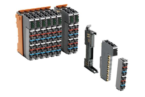
This new bus is geared toward applications that involve many I/O modules or high data volume but where short cycle times are imperative. It is even possible to set up two separate cycle times so that less time-critical data is transported more slowly and generates less network and processor load. In this way, complex high-speed processes can be controlled reliably using cost-effective standard hardware.
B&R Automation / www.br-automation.com/
Pepperl+Fuchs isolators
The K-System from Pepperl+Fuchs offers a portfolio of isolators for any interface requirement. The K-System interface modules are designed to guarantee a reliable and economical signal transmission between field device and the control system and offer quick and convenient installation due to simple mounting on a standard DIN rail. Modules are added by clipping them in. The power rail ensures a reliable power supply. Pepperl+Fuchs / www.pepperl-fuchs.com/

Each FSoE slave device has four safe inputs, two safe outputs and four OSSD outputs. A single FSoE master can control up to 65,535 slave devices.
KEB America / www.kebamerica.com
Dinkle hybrid terminal block
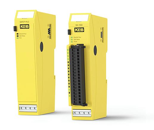
Dinkle offers the Push-in Lever UP (P-LUP) hybrid terminal block series, designed for tool-free operation in factory and field wiring applications. The P-LUP series features Dinkle’s hybrid lever structure in a compact, ergonomic design that is designed to reduce space requirements. The internal mechanism allows the lever to be rotated by the handle, activating the push-in function to securely connect or release wires for effortless wire insertion and removal without tools. Combined with Dinkle’s push-in design technology, the hybrid P-LUP series is designed to de liver high-performance connectivity and a streamlined installation process for modern electrical systems.
Dinkle / www.dinkle.com/

Weiland Electric safety controller
KEB America safety system
KEB offers a complete system that is compliant with safety standards IEC 61508 SIL 3 and DIN EN ISO 13849-1 Ple. The system includes the C6 Safety PLC, Safety I/O modules and programming software. These modules have a doublechannel design and can be programmed through COMBIVIS studio 6. The Safety PLC is a Fail Safe over EtherCAT (FSoE) master that works in conjunction with the machine PLC to execute and monitor safety functions. The Safety PLC can connect with other FSoE slave modules like Safety I/O and servo drives that have Safe Motion functionality.
Wieland’s samos Pro Motion is a compact, programmable and modular safety controller for safe monitoring of speed, position and direction of rotation. It features up to 24 I/ Os (16 safe inputs, four safe outputs, four configurable) and supports Profinet I/O, EtherNet/IP and Modbus TCP. Functions like standstill, SLS, SSR, SMS, SDI and SLP per EN 61800-5-2 are programmed using the license-free samos PLAN6 software. Integrated communication is designed to enable seamless transmission of motion data to higher-level controllers, HMIs and IIoT platforms, ensuring safe, intuitive and scalable motion control for a wide range of automation applications.

Weiland Electric / www.wieland-americas.com
Altech terminal block
Altech’s ATEX-IECEx-approved terminal blocks are designed for greater safety and reliability in explosive environments. The ATEX-IECEx Directive considers both electrical sources of explosion and potentially explosive concentrations of gas, vapor, mist and dust in the air. Altech’s terminal blocks are designed for a maximum service termperature of 110 °C with an ambient temperature range of -60 °C to +66 °C. Wire sizes range from 24 AWG up to 250 kcmil. The terminal block technologies include tool-less connection, stainless steel push-in spring, universal push-in jumper system, compact design, strong clamping system and snap-on ground blocks.
Altech / www.altechcorp.com
copper for optimum conductivity. All materials have been tested to current environment guidelines.
Newark / www.newark.com
Omron light curtain
Struggles with light curtain setup and maintenance lead to downtime, higher costs and frustrated teams. The Omron F3SG-SR series is designed to streamline installation with quick alignment, no dead zones and easy programming. During production, it is designed to provide critical status updates and preventive maintenance data via I/O Link or Bluetooth to prevent stoppages. With muting, blanking and high protection ratings (IP67G to IP69K), it is designed to meet demanding safety needs while cutting costs.
Omron Automation Americas / automation.omron.com

Weidmuller terminal block connection technology
Weidmuller’s Snap In connection technology options are included in its fuse and disconnect terminal blocks, as well as bigger cross-sections and three-tier terminal blocks on its feed-through and ground options. Weidmuller offers availability of wiring technology for wires as small as 22 AWG and up to 4 AWG. With Snap In, flexible conduc tors without ferrules can be connected without tools, even in fully automated wiring processes.
Weidmuller / www.weidmuller.com/
Newark terminal block

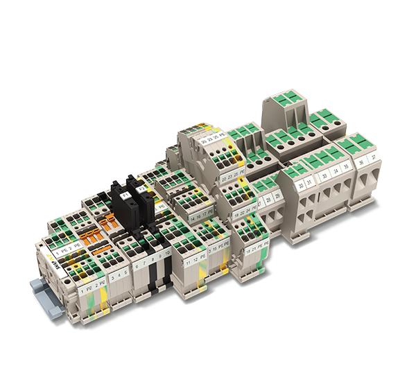
Newark’s 1021500000 is a double-tier feed-through terminal block with screw connection for screwable crossconnection and 2.5 mm² wire cross section area, M2.5 clamping screw and 10 mm stripping length. With dark beige color, TS 35 rail mount and snap-on mounting, the WDK 2.5 terminal block accepts 26AWG minimum to 12 AWG maximum wire size. It includes hardened steel for mechanical strength and tinned
Siemens clean technology
Siemen’s ET 200clean is designed to offer a reliable and flexible product for the automation of the relevant production processes. It consists of compact I/O devices in hygienic design with M12 connection technology for processing digital and IO-Link signals for connection to bus systems with Ethernet-based protocols such as Profinet, EtherNet/IP and Modbus TCP. The modules are Ecolab certified for use. The special housing is designed to enable hygienic 360° cleaning, effectively removing impurities and preventing germs. Simantic ET 200clean is designed for demanding and high-availability applications. Siemens / www.siemens.com/
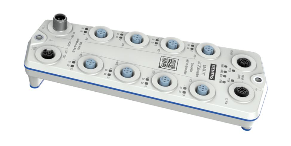
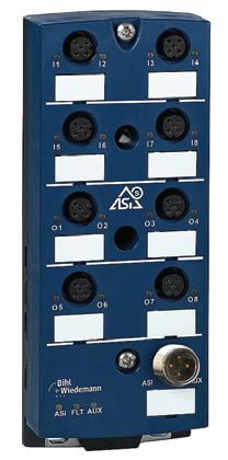
Bihl+Wiedemann Asi-5 digital I/O module
Designed to gain maximum flexibility and minimize clutter, Bihl+Wiedemann’s Asi-5 digital I/O module allows up to eight digital inputs/outputs.
Bihl+Wiedemann / www.bihl-wiedemann.com
Compact machine control with flexibility
KEB AMERICA’S C6 COMPACT 3 is the next generation of control in its ecosystem. It is based on the Linux operating system (OS) and offers an open architecture. The container-based technology allows software functions to be integrated and organized, and the controller can be programmed using IEC 61131-3 languages.
The C6 Compact 3 is 25 x 100 x 132 mm and DIN-rail-mountable, and it operates on 24 Vdc in temperatures ranging from -20 °C to 55 °C.
“The C6 Compact 3 was created as part of our Next Open Automation (NOA) platform, which fulfills several customer needs,” explains Scott Cunningham, product and application manager, controls and automation, at KEB America. “The foremost need is the possibility to provide functionality and security updates via our NOA ecosystem as new regulations and requirements go into effect around the world. Customers can simply connect the device to the internet, log in to the web-based portal and view required and available updates and activate them. Furthermore, with our NOA Portal fleet management functionality, the customer can perform these functions from one central location.”
Product flexibility is another need the device aims to fill. “With the C6 Compact 3, customers can add or even remove functionality as needed,” says Cunningham. “As part of the NOA world, functionality is defined by which ‘apps’ are installed on the device.” If the customer needs OPC UA, Helio or robotic motion control, it can be added. “Ultimately, the customer
only needs to know the hardware needs at time of order,” he says.
KEB identified a need for small, economical motion-based and coordinated motion controls that can be programmed using IEC 61131-based languages. “The C6 Compact 3 fits in that space perfectly,” explains Cunningham.
IEC 61131-3 languages are not new to KEB. “We adopted it at the start of our controls program and have seen users become more comfortable with the different languages and their applications,” explains Cunningham.
The concept of small, motion control within the NOA space started about five years ago. The design, a modernization of the C6 Compact II, comes from the C6 Compact lineage, which originated around 20 years ago. “This product line is our single-board motion control, traditionally embedded,” explains Cunningham. “To meet growing features and security needs, we moved to Linux, an OS-based solution.”
Linux provides many advantages, says Cunningham. “First and foremost is the ability for KEB to support ourselves if a problem arises,” he explains. “If there is an issue with a hardware driver or a security update, we can make changes to the Linux core. This also means that we share this improvement to the Linux source. This concept of ‘use, improve and share’ is multiplied over all of the Linux users and developers in the world.”
The unit is designed for two main use cases. “For compact machines, the Compact 3 can be the whole machine control, working with the full KEB product offering of remote I/O, drives

For more information Visit www.kebamerica.com.
and gearmotors,” says Cunningham. “It really allows the customer to one-stop shop their automation needs. In larger, more demanding machines, the Compact 3 can be the motion sub controller, removing the demanding motion control needs from the main machine PLC, removing complexity and cost of motion cards and licenses.”
A big part of KEB’s implementation of the OS side of its next-generation controls, such as the Compact 3, is the usage of containers. “Each NOA application is a container running on the operating system,” explains Cunningham. “It is completely isolated from any other containers and can easily be installed or removed with a click of a button. Most importantly, the control does not need to be rebooted.” Customers can even create their own containers and install them without worrying about affecting the motion control or any other application running.
Joey Stubbs joey.stubbs@gmail.com

Industrial HMIs get a smart phone upgrade
SMART PHONES HAVE BECOME synonymous with userfriendly, intuitive devices. Many are the stories of children who grab a cell phone for the first time and quickly learn how to navigate and use the device.
Many of the qualities that make the cell phone interface so intuitive are enabled by the hardware of the humanmachine interface (HMI) display itself. At long last, many of those same hardware features are finding their way to the operator interfaces that are the front end of factory and process equipment. This makes the HMI more akin to the devices we use and carry every day, and it adds to the general user-friendliness of the interface.
smaller display to have the same functional area as a larger one or the same size bezel now offers more display area.
Many HMI panels have enough spare processing power that they can be used as edge devices.
We are accustomed to using multiple fingers for many actions on our personal screens, such as pinch to zoom, two-fingered scrolling and swiping actions. These features are enabled by multi-touch technology. One additional major improvement that multi-touch brings to industrial HMIs is having to use a second finger on a designated area of a screen that enables the HMI’s other buttons. This two-hand requirement reduces false or accidental operations on the screen.
Swiping, scrolling and pinch-to-zoom actions can be very useful for HMI screens for zooming in or out of graphics of an assembly line to analyze where a fault or error originates, scrolling over a single large graphic of a factory line instead of having it split into several separate pages or to zoom in and out of a document or operating manual that gets pulled up as part of operations.
Similarly, touchless gesture support is enabled by cameras on the front of the display, and it gives some ability to activate the screen without physical contact. For areas with contamination concerns, such as cleanroom environments, this can be a very important technology that helps avoid both the cost and wear of cleaning the panel frequently.
As display technology improves, one trend for HMIs has mirrored consumer devices: edge-to-edge displays. By minimizing or eliminating the dead space around the display, they maximize the available screen area. This allows a
Providing a physical, tactile feedback to the operator’s touch inputs closes a sensory disconnect between the operator and the response from the HMI screen. A small bump or vibration can indicate that a virtual button is activated, very helpful in general but also becoming more critical in noisy environments where an audible click would not be an effective feedback mechanism. As haptic technology evolves, expect the ability for the user to feel and differentiate virtual buttons, switches and valves and even distinguish different textures, improving the tactile information back to the user. Beyond just the benefit of speedy graphics and communications, however, many HMI panels have enough spare processing power that they can be used as edge devices themselves. Running analytics or machine learning tasks directly on the panel is now a reality. Supervisory control and data acquisition (SCADA), predictive-maintenance (PdM) tasks and quality alerts can run on the same panel as the HMI program.
Of course, just as our cell phones have evolved into tough, waterproof devices that can survive an accidental dip in the pool or drop on the sidewalk, so have operator panels become ruggedized to survive vibration or water/dust ingress. Washdown models for food and beverage industries are completely sealed and waterproof, adding to the cost savings of having to build custom waterproof enclosures for the HMI.
Just as consumer products have driven advances in the automation industry with relation to communications, such as standard Ethernet fieldbuses, Wi-Fi and Bluetooth, so has the operator interface benefitted from consumer cell phone and tablet interfaces.
Joey Stubbs is a former Navy nuclear technician, holds a BSEE from the University of South Carolina, was a development engineer in the fiber optics industry and is the former head of the EtherCAT Technology group in North America.