Accudraft LIVE is an advanced automated paint booth control system designed to enhance efficiency and reduce downtime. In a recent discussion, Jeremy Winters, marketing and content creator for Accudraft, talked with FenderBender and ABRN Editor-in-Chief Jay Sicht to explain how this cloud-based paint booth software provides real-time monitoring, remote diagnostics, and predictive maintenance capabilities. By tracking key metrics such as filter usage monitoring, airflow, and temperature, shop owners and operators can proactively address issues before they lead to costly repairs. Learn
EVP VEHICLE SERVICE/REPAIR GROUP AND FLEET AND TRAILER GROUP CHRIS MESSER
BUSINESS STAFF
MICHAEL WILLINS
BUSINESS DEVELOPMENT DIRECTOR, MOTOR AGE TRAINING
LESLIE BROWN CUSTOMER MARKETING MANAGER
MARIAH STRAUB PRODUCTION MANAGER
JENNIFER GEORGE AD SERVICES MANAGER
TRACY SKALLMAN AUDIENCE DEVELOPMENT MANAGER
JILLENE WILLIAMS SALES COORDINATOR
JAMES HWANG Inside Sales & Brand Manager, ASE Study Guides jhwang@endeavorb2b.com
REPRINT SERVICES reprints@endeavorb2b.com.
CUSTOMER SERVICE Subscription Customer Service 877-382-9187; 847-559-7598 ABRN@omeda.com PO Box 3257 Northbrook IL 60065-3257
ABRN is published 4 times yearly (March, June, October, December) by Endeavor Business Media, LLC. 30 Burton Hills Blvd, Ste. 185, Nashville, TN 37215. Customer service can be reached toll-free at 877-382-9187 or at ABRN@omeda.com for magazine subscription assistance or questions.
Printed in the USA. Copyright 2025 Endeavor Business Media, LLC. All rights reserved. No part of this publication may be reproduced or transmitted in any form or by any means, electronic or mechanical, including photocopies, recordings, or any information storage or retrieval system without permission from the publisher. Endeavor Business Media, LLC does not assume and hereby disclaims any liability to any person or company for any loss or damage caused by errors or omissions in the material herein, regardless of whether such errors result from negligence, accident, or any other cause whatsoever. The views and opinions in the articles herein are not to be taken as official expressions of the publishers, unless so stated. The publishers do not warrant either expressly or by implication, the factual accuracy of the articles herein, nor do they so warrant any views or opinions by the authors of said articles.
Endeavor Business Media provides certain customer contact data (such as customers’ names, addresses, phone numbers, and e-mail addresses) to third parties who wish to promote relevant products, services, and other opportunities that may be of interest to you. If you do not want Endeavor Business Media to make your contact information available to third parties for marketing purposes, simply call toll-free 877-382-9187 or email ABRN@omeda.com and a customer service representative will assist you in removing your name from Endeavor Business Media’s lists. ABRN does not verify any claims or other information appearing in any of the advertisements contained in the publication, and cannot take responsibility for any losses or other damages incurred by readers in reliance of such content. ABRN welcomes unsolicited articles manuscripts, photographs, illustrations and other materials but cannot be held responsible for their safekeeping or return.
ADVERTORIAL
Fix it the way they built it
Shop techs are pros. So are OEMs. Following specs is how they work together.
Nobody knows vehicle repair like auto body shop owners and operators. But nobody knows each specific vehicle like the manufacturer who built it. When a vehicle comes into a shop, the best results happen when both kinds of experts guide the process. For body shops, that means bringing the manufacturer “in”—virtually, not physically—by following OEM specs for parts, supplies and procedures.
Only about one-third of shops use the correct automotive OEM specifications. But that’s a practice that can cost them in the end.
What does that cost them? In the front door, it can sap business volume if an insurer sends vehicles to a different shop with OEM certifications, procedures or products. Out the back door, invoice reimbursement for materials can suffer if the shop can’t show it used OEM products.
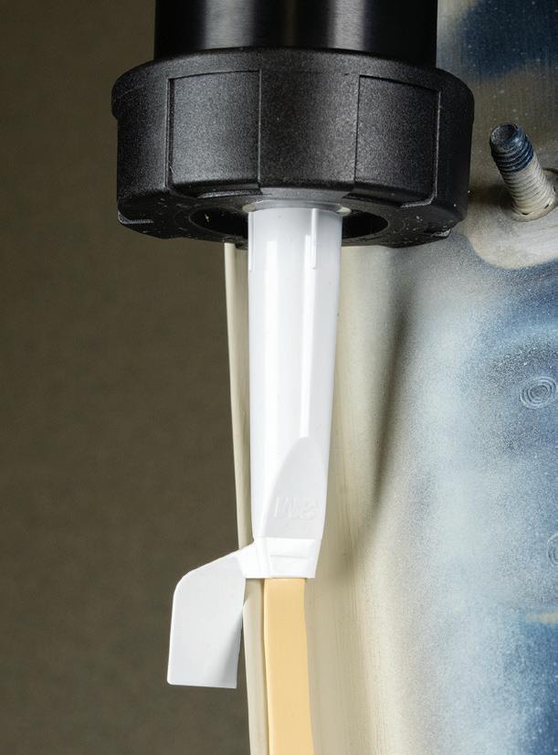
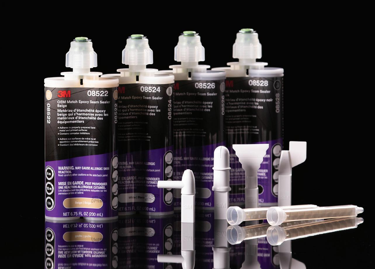
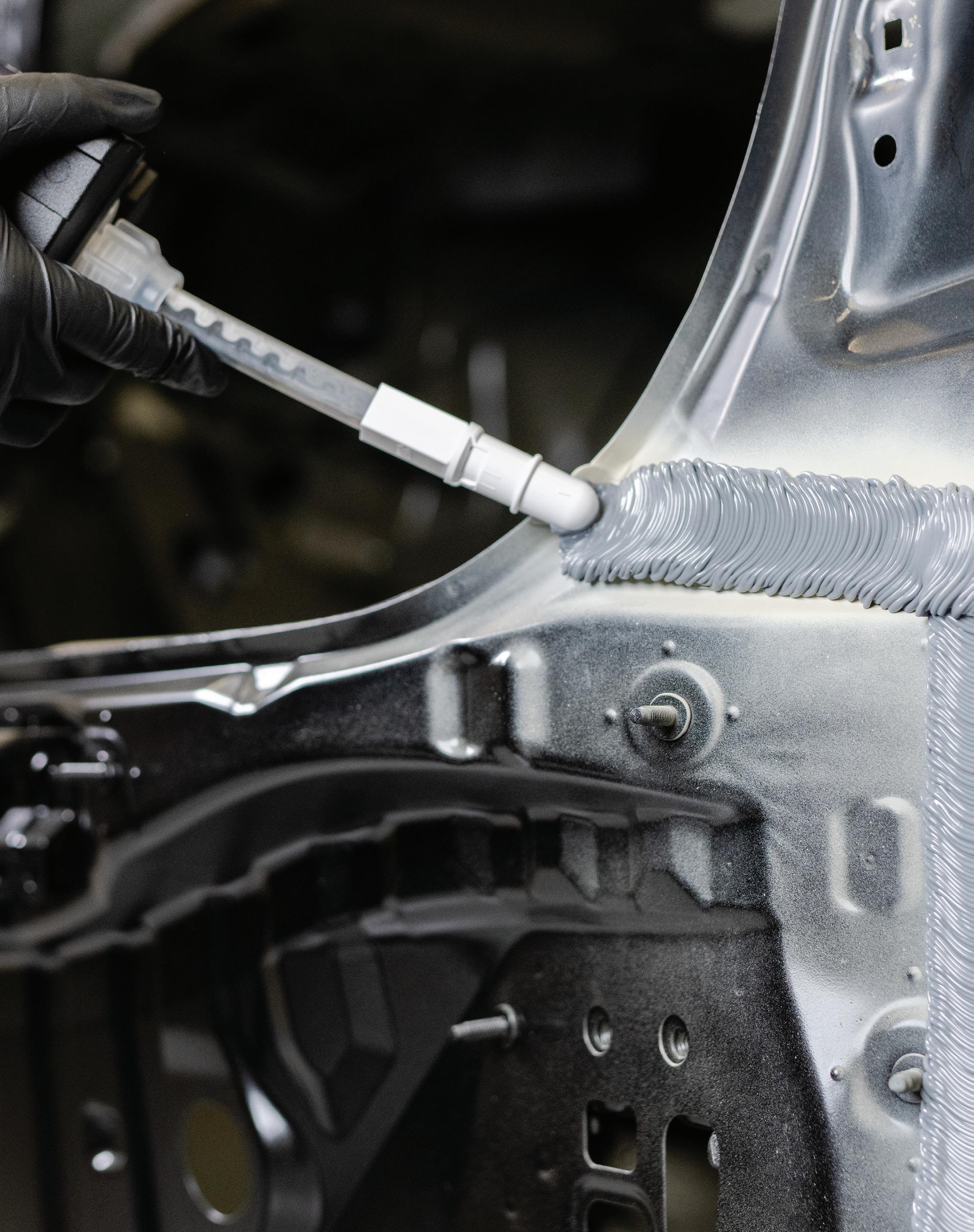
In addition to parts, many OEM-documented repair procedures specify consumables like paints, abrasives, adhesives and seam sealers. To help shops follow those specifications, 3M has introduced a line of OEM Match 2K Seam Sealers and corresponding tips that can achieve the right performance and appearance the first time, with less waste and cleanup time.
“Because vehicle design and materials are increasingly complex, the repair plan is getting more complex as well,” says 3M Global AOEM Application Engineering Advanced Specialist, Branden Loesch. Before starting the repair, estimators and technicians should head to the OEM technical information sites, to research the OEM repair procedures and position statements that manufacturers publish online and update regularly.” Surprisingly, it’s common to skip that step, or to rely instead on third-party guides that might not be accurate, model-specific or timely.
Along with OEM documentation to start the job, techs should factor documentation into finishing it as well— except this time, they’re the ones writing it. Cataloguing all the OEM materials they use on a job can provide the critical information that gets an invoice paid in full, and 3M™ RepairStack™ Performance Solutions can help automate that process by using billables invoicing to help increase profitability by enabling you to track and bill for materials you use ensuring that all costs are accurately accounted for and passed on to insurance. Photos and scans are
also a common part of the process that shouldn’t be overlooked.
Choosing to stock and work the OEM Way is a win-win—it makes financial sense for the shop and delivers safe, proper repairs to customers’ vehicles. That’s a boost to reputation. It’s also a safeguard against potential liability.
Shop owners and their techs pride themselves on knowing the cars and the job, and they should. You can spot a shop where veterans use hard-won institutional knowledge and pass it on. Relying solely on experience without consulting up-to-date manufacturer specifications can lead to missed steps, rework, or noncompliance. To maintain repair integrity and ensure proper outcomes, that legacy knowledge must now be paired with realtime OEM documentation. In today’s repair environment, technical accuracy depends on both. That’s the standard. That’s the OEM Way.
OEMs reference specific products and tools to complete the repair for a reason. They have been rigorously tested to OEM’s performance requirements for strength and corrosion resistance.
3M is more often referenced in OEM repair procedures for panel bonding and impact resistant structural adhesives than any other adhesive supplier.
Want to know more about OEM recommended products?
AVTECC’S EV SAFETY CERTIFICATION PREPARES TECHNICIANS TO WORK ON ELECTRIC VEHICLES
A new hands-on, performancebased EV Safety Certi cation for technicians is now available from the International Advanced Vehicle Technology Education and Credentialing Coalition.
The AVTECC EV Safe Certification is designed for transportation techni-
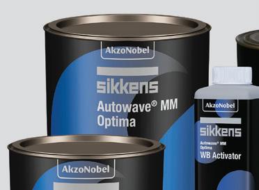
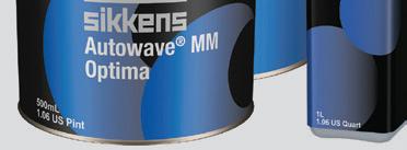
NEW SIKKENS AUTOWAVE OPTIMA OFFERS ‘ONE-STOP’ APPLICATION
AkzoNobel has launched Sikkens Autowave Optima in North America, a new one-stop application waterborne basecoat that improves body shops’ productivity and sustainability, according to the company.
It’s said to offer up to 50% faster processing times compared to conventional basecoat application methods. With perfect coverage in just 1.5 layers due to its high pigmentation, it can save an average of about 15% of paint material.
Technicians don’t need to flash-off between layers; they can go into the spray booth once. The fast application times translate into 60% lower energy costs and a reduction in carbon emissions of up to 60% compared to a conventional basecoat along with 380 grams per liter of VOCs, which is 10% lower than the 420 grams per liter legislation. All performance data quoted is based on AkzoNobel’s benchmark testing.
cians working in the light, medium, and heavy-duty sectors of industry.
“AVTECC’s EV Safe Certification is a hands-on safety certification designed to assure that technicians have the skills to work safely on electric vehicles,” said David Macholz, president and CEO of AVTECC. “With safety critical technolo-
“This basecoat reflects the DNA of our company, and our commitment to addressing the key challenges of body shops — sustainability and efficiency — saving valuable time and energy through our advanced coating technology,” said John Griffin, director of AkzoNobel’s Automotive & Specialty Coatings business in North America.
The new generation basecoat delivers high color accuracy and a reliable color match through a seamless 100% digital color process with AkzoNobel’s Automatchic spectrophotometer and Mixit color retrieval software. Customers can use AkzoNobel’s Refinish+ digital platform to track KPIs and improve business performance. The Carbeat production workflow dashboard can also help to drive operational efficiency.
gies that may pose a risk to technicians, a traditional multiple-choice assessment does not provide the level of assurance
required to indicate they can work safely on these complex vehicles. Our EV Safe certification requires technicians to demonstrate their skills on a live vehicle in real-world working conditions.”
The EV Safe Certification is the first in a series of performance-based certifications AVTECC will release in 2025. It addresses the critical safety considerations related to working on and around high-voltage electrified vehicles that pose potential risks to technicians, the related workforce, and potentially to vehicle owners and operators if not properly maintained and repaired.
To develop the certification, AVTECC engaged a panel of electric vehicle subject matter experts including technicians, technical training managers, field service personnel, technical trainers, and educators from vehicle OEMs, independent training entities, and higher education.
“We designed the AVTECC EV Safe Certification to be more than industry recognized,” Macholz said. “We have strong interest from the automotive sector in not only recognizing the certification but utilizing it within their training organizations. We believe this assessment will become the industry standard here in the U.S. and abroad.”
For more information, visit the AVTECC website at avtecc.org.
AKZONOBEL
TECHNICAL
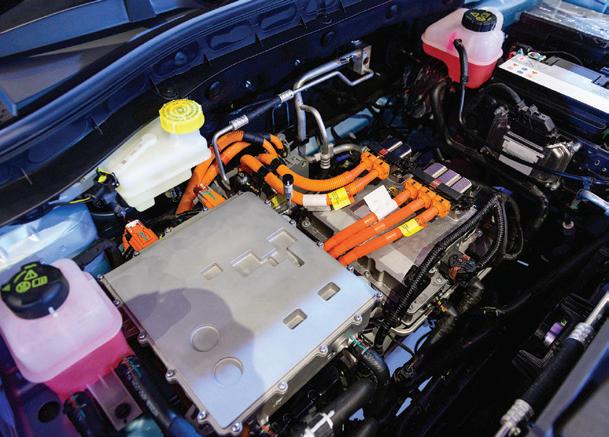
As with any repair, be sure to stick strictly with OEM guidelines. Critical sensors can be affected by welding and changes in coating thickness.
PLASTIC REPAIR POSSIBILITIES
LET THESE FIVE POINTS GUIDE YOU IN YOUR PLASTIC REPAIR JOURNEY.
BY TIM SRAMCIK
Review the following two repair scenarios and select the one that best describes your operation.
Scenario one: A vehicle is brought into your shop with front-end damage, including some tears in the plastic bumper cover. Your estimator puts in a parts order for a new cover, which your techs later install and paint.
Scenario two: A vehicle is brought into your shop with front-end damage, including some tears in the plastic bumper cover. Your estimator recommends a nitrogen-welding repair to the plastic, which one of your techs performs.
In both cases, you’re looking at a relatively simple, quick repair. But there is a critical difference in cost and convenience. In scenario one, you’re spending money on a part, with most of that cost going to a vendor, and not your shop. In the second, costs are lower, and that money goes directly into your pocket while saving both your customers and insurers some significant cost.
Why isn’t scenario two the standard for the industry? Plastic repair experts say too many shops stick with the replacement option because they either gave up too early on plastic repairs or they believe this work is too specialized
for their businesses. Don’t let these views affect your shop’s plastic repair journey. Use these five points, submitted by repair experts, to guide your way into adopting this accessible, revenue-generating work.
POINT 1: You can do it.
John Wilburn, chief plastic welding instructor at Polyvance, says he’s visited a number of shops that eschew plastic repair for various reasons. “You see plastic welding equipment
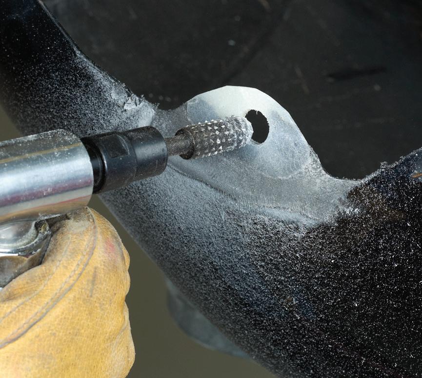
pushed into a corner because someone at the shop tried some repairs and maybe didn’t like the results, and the shop simply gave up,” he says. That’s unfortunate because with the right investment of time and training, practically every shop can do the work, which involves using prep products and tools, plastic adhesives, nitrogen welders and plastic welding bits to fix tears, holes and other damage.
Moreover, the work matches up well with metal welding. As with metal work, Wilburn says learning plastic repairs
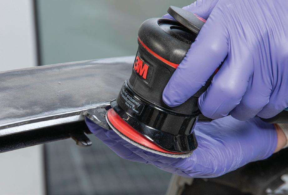
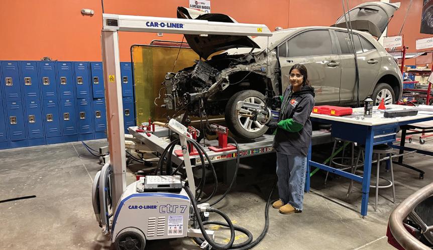
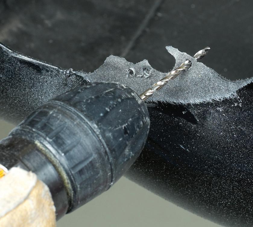
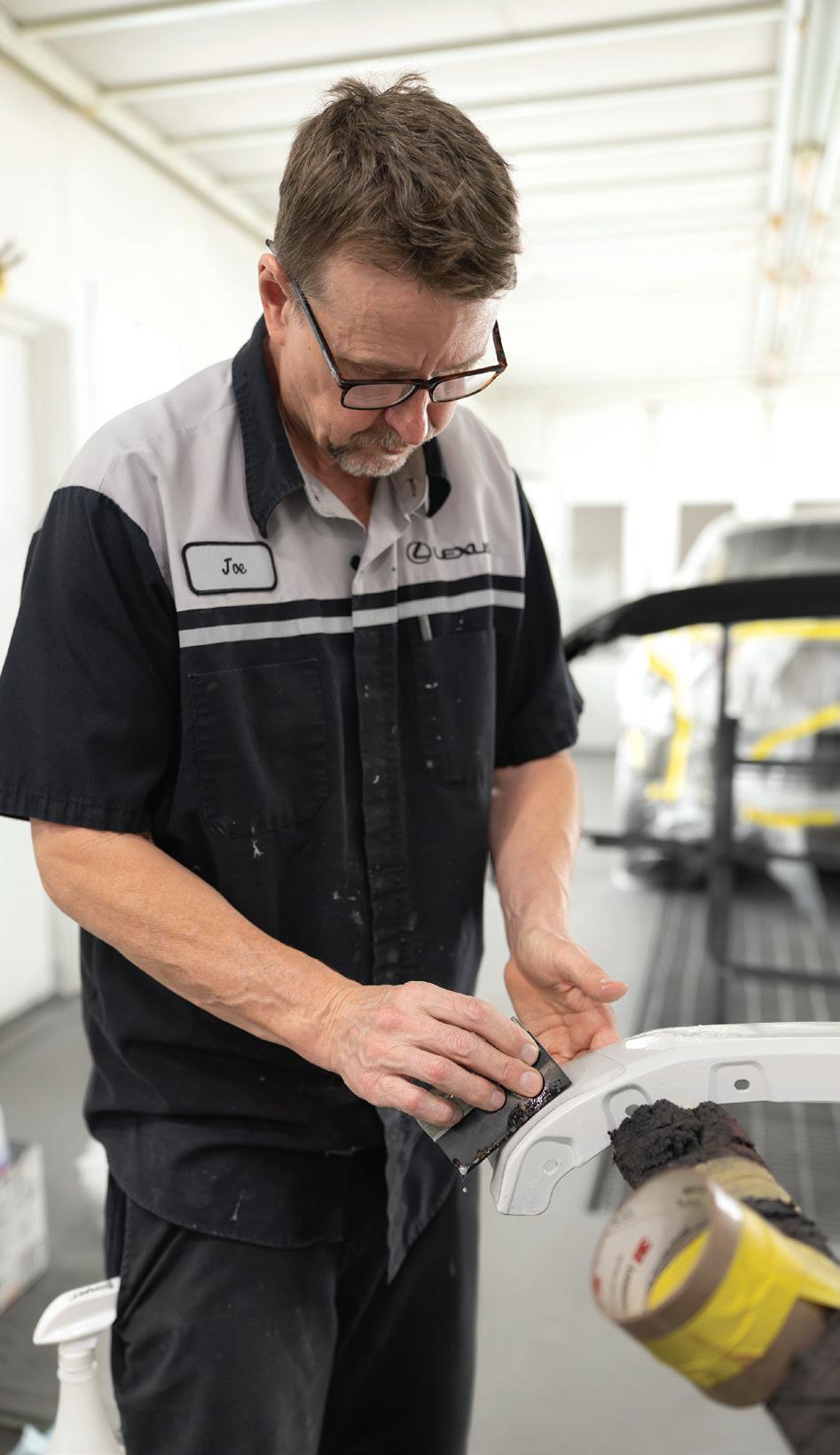
Plastic repair utilizes the same skills your techs already possess. With some training and experience, they can add another critical revenue stream to your business.
Repairing tabs and other plastic pieces allows you to avoid sometimes costly parts replacement while rewarding your shop with more direct repair dollars. 3M
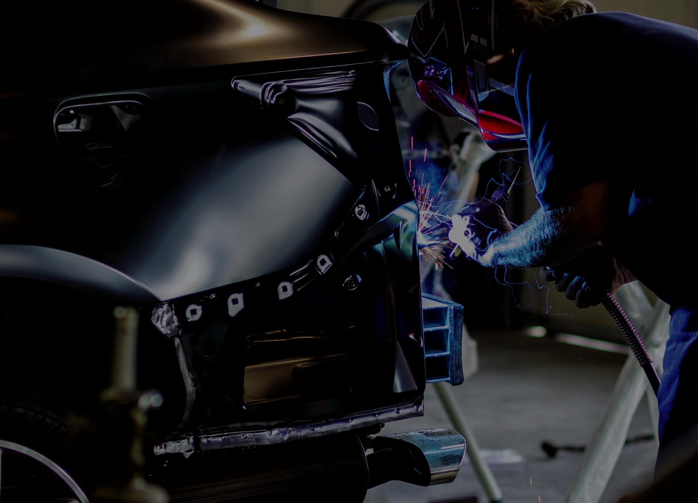
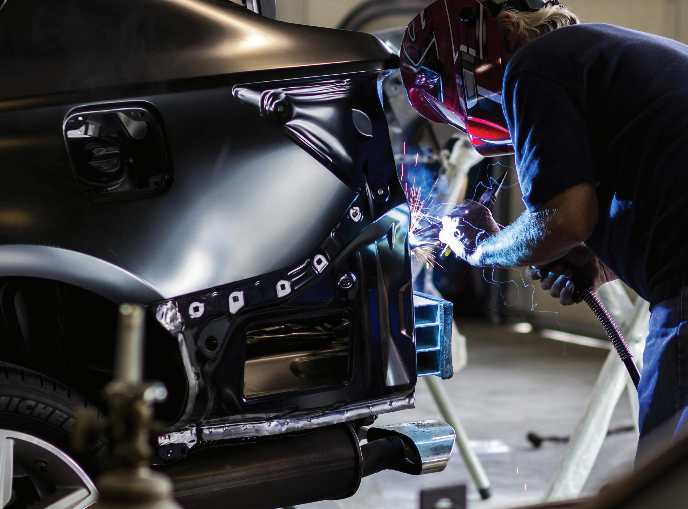
With some training and standard plastic repair tools, you can perform welding repairs like this every day.
begins with technicians using basic skills then ramping off those with experience to build technical acuity. Shops should have plenty of opportunities to build skills (and revenue) considering the number of plastic parts that can be repaired, including fender liners, radiator overflow tanks, interior pieces, and many more.
POINT 2: Training is readily available.
Getting started with plastic repair and honing skills should not be an issue since training is available through Polyvance, I-CAR, and 3M, among others. Wilburn notes that Polyvance houses training videos and information online, including
step-by-step content on starting, maintaining and using welders to perform basic repairs. More advanced courses offered through 3M and Polyvance count toward I-CAR certification. Wilburn recommends estimators attend training sessions, so they’re better prepared to include plastic repairs on a work order.
POINT 3: Technology is making plastic repair work easier.
Some new products are taking some of the biggest challenges out of this work, the first being the proper identification of the plastic type being repaired. A common
misconception among repairers is that the color of a plastic can be used for identification. Wilburn points out plastic is actually identified by a symbol stamped on the part used to match it to the correct welding rod. From there, the technician refers to an instruction guide or chart to properly set up the welder for the specific plastic type. Polyvance recently introduced its Nitro-Fuzer Touch with Tru-Fuze Technology, which features preprogrammed settings for over 20 of the most common plastic types. This eliminates the need to determine optimal temperature and flow settings, which saves time and ensures accuracy.
POINT 4: The plastic repair landscape doesn’t change much.
When delving into any unexplored, or relatively unexplored, technology, shops face the prospect of investing in technology that regularly demands continual outlays of new money. Both Wilburn and Shawn Collins, advanced application engineer at 3M, say this hasn’t been the case with plastic repair, as this work has remained relatively unchanged for at least the last 20 years. “We can’t predict what auto manufacturers will do in the future, but this area has seen very little change in the time I’ve been involved,” Wilburn says. Collins notes that he, too, has seen little change in the part of the repair landscape, with previous projections of plastic being replaced with other materials like carbon fiber never materializing (mainly due to costs). Both note that plastic welding techniques haven’t changed much, either.
All this adds up to a steady repair field, marked by upgrades in specific technology with no significant transformations in its foundations, that shouldn’t turn away any shop.
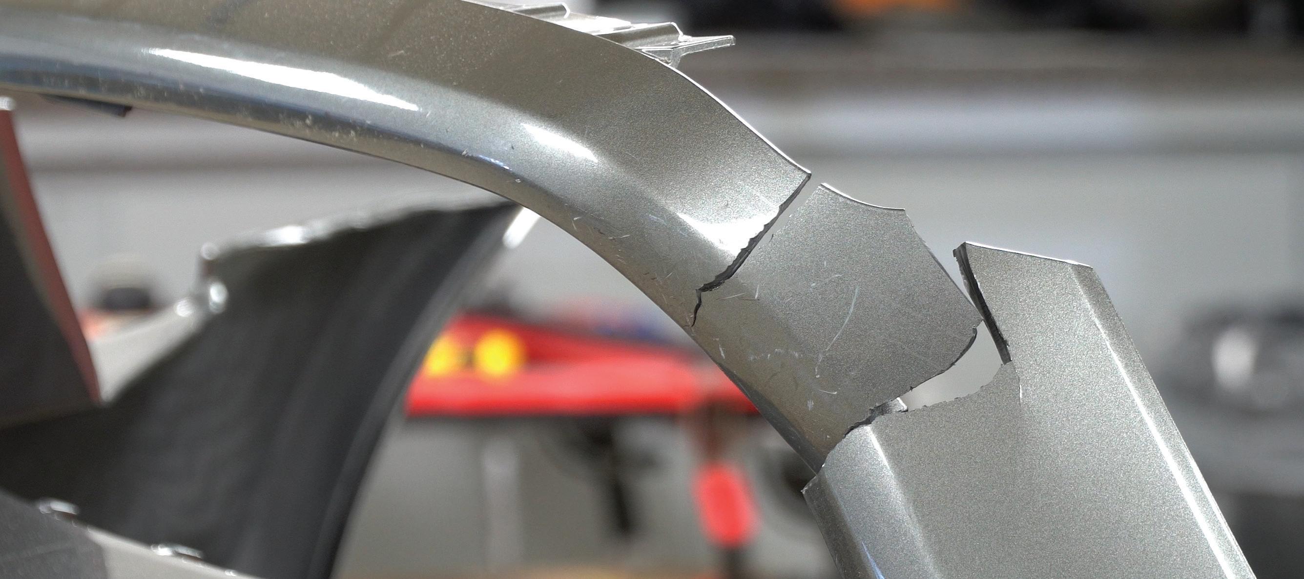
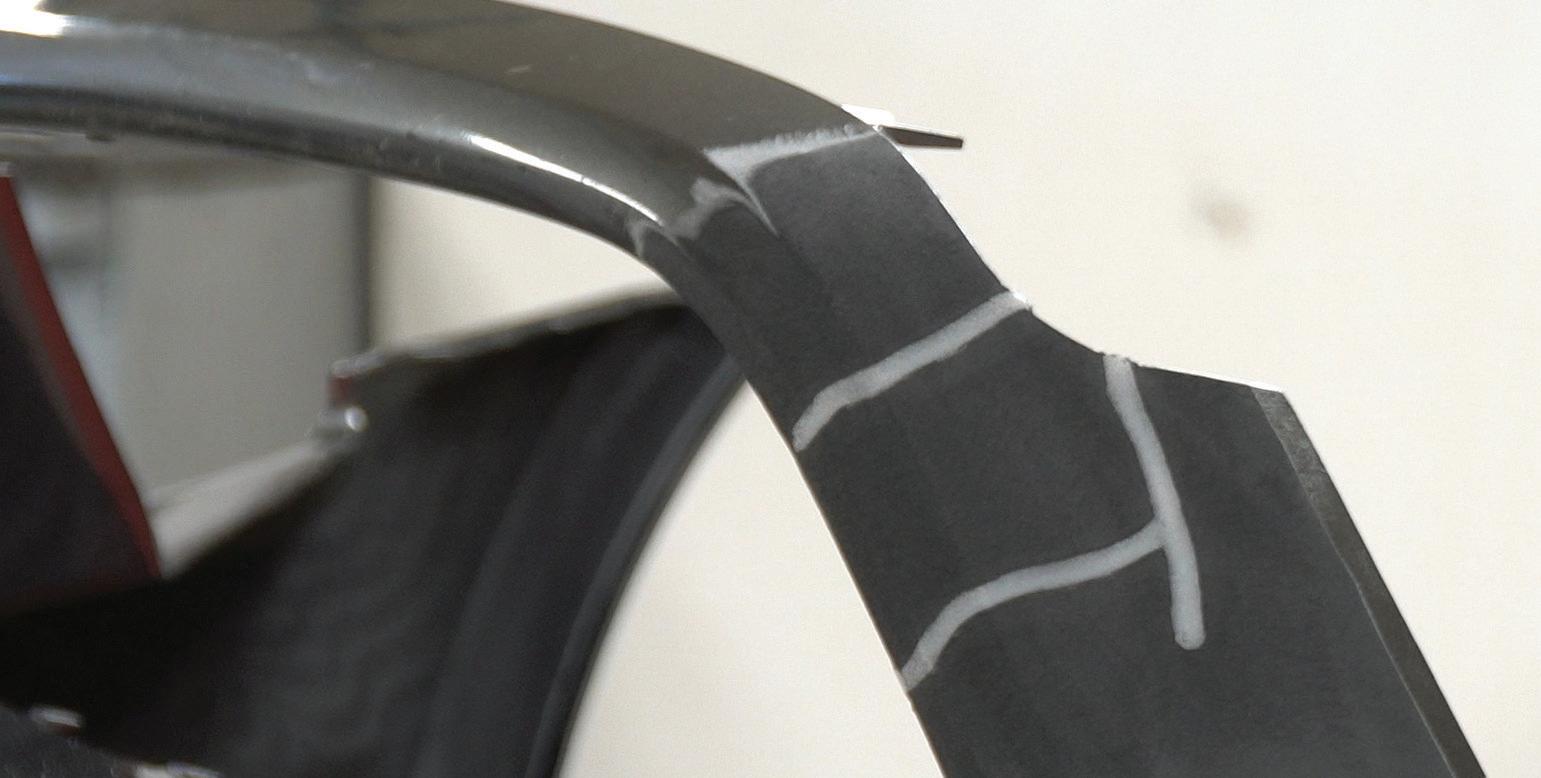
POINT 5: You’ll need to stick with OEM guidelines.
Plastic repairs are not without a few significant developments. According to Collins, evolutions in automotive technology can affect either specific areas of the plastic part or its entirety that could restrict its repair. This, of course, has to do with the location of sensors and factors such as the depth of finishes. Collins says these challenges, more than ever, compel shops to consistently refer to OEM repair guidelines.
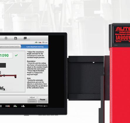
“The latest challenges are what you can repair. “Take Volkswagen,” he explains. “Restrictions for repairs to the front bumper cover are as follows: Do not exceed the maximum paint coat thickness of 150 microns in the area of the control modules or lane-change assistance. Plastic repair performed in this area in the vicinity with a minimum distance of 25 centimeters. Smoothing performed in the same area requires a minimum distance of 25 centimeters.”
Collins stresses that repair guidelines differ from one manufacturer and model to the next. “A Mazda bulletin on polypropylene bumper covers states that damaged bumper covers on models with blind spot monitoring must be replaced,” he says. “If the bumper around the BSM is damaged, Mazda says the bumper has to be replaced.”
Volvo provides guidelines that include images of bumpers with shaded areas indicating zones that can’t be repaired. Further, Volvo states that the products used on its bumper covers have undergone its very stringent requirements and quality tests since metallic particles in car paint can deflect and/or distort radar beam energy being transmitted through the layers. Repairers are instructed to minimize the total thickness of existing metallic paint and any coatings before applying new layers, so there won’t be excessive film build.
(NOTE: Please refer to full guidelines provided by each manufacturer.)
As with much repair information, you may need to do some digging to find full instructions. Collins notes that OEMs continue working hard to provide accurate repair steps, but shops need to remain diligent to seek out this information. This fact shouldn’t scare off shops from plastic work since it’s true for any other part of a repair.
Companies like Polyvance and 3M do provide support, but both Wilburn and Collins caution that they can only provide information on their products, not on specific repairs. But this product information and the SOPs for using it are “bulletproof,” Collins says.
That’s one less worry for shops. Making this work less worrisome is the goal of plastic repair experts. Whether you’ve never attempted plastic repairs or perhaps gave up on them at some point, now might be a good time to speak with vendors and reassess these decisions. Your shop has the skills. The equipment and training are available. Your future is what you make of it.
TIM SRAMCIK began writing for ABRN over 20 years ago. He has produced numerous news, technical and feature articles covering virtually every aspect of the collision repair market.
In 2004, the American Society of Business Publication Editors recognized his work with two awards. Sramcik also has written extensively for Motor Age and Aftermarket Business World. Connect with Sramcik on LinkedIn and see more of his work on Muck Rack.
SCAN THE QR CODE TO SHARE THIS ARTICLE AND READ RELATED ARTICLES ONLINE
ARE YOU READY FOR THE BOOTH ARE YOU READY FOR THE BOOTH
THESE 5 STEPS KEEP PAINTERS ORGANIZED AND HIGHLY PRODUCTIVE.
BY TROY KNOPIK
As the last stop for a vehicle when moving through the repair process before reassembly occurs, the paint shop is often referred to as the “bottleneck” of a collision repair center. e truth is that every vehicle will need to go through the paint department at the appropriate stage of the repair process. To better enhance throughput and productivity, collision repair facilities should take the time to prepare and implement a standard operating procedure (SOP) to help address the bottlenecks that can occur.
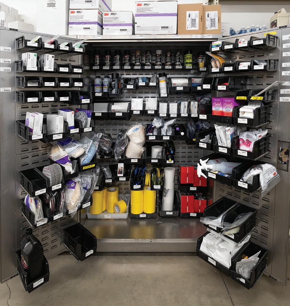
Materials
2
While it may sound simple, the importance of being properly stocked with the required liquid and allied materials cannot be underestimated. All paint technicians should check and be aware of whether there are sufficient materials on hand to finish the paint work listed on the booth schedule for that day. This will help minimize any production loss and assist the paint department with remaining efficiency. Potential delays and inefficiencies could include being out of stock of a particular toner required to mix the paint and having to wait for it to be delivered. Booth time and throughput are critical, so it is important to maximize each booth cycle throughout the day. The average shop in the U.S. completes three to four booth cycles per day, and delays caused due to out-of-stock scenarios could potentially cost a booth cycle - which ultimately slows down production.
3
Review your work order and use a booth schedule
It’s important to review the complete estimate early on with the body tech or production manager to ensure everything required to complete the repair is available in the shop for when the vehicle arrives and work is scheduled to commence. Reviewing the estimate will also highlight important items that may be in the “notes”
Ensure you have the liquid and allied materials needed on hand before beginning the job.
section on a work order. A highlighter is a great way to mark off the items and gives an easy visual reference to all parties involved that a work order has been reviewed thoroughly. This process will help limit the delays in the collision center.
CHECK STOCK:
TAYLOR HAYDEN/TMH CREATIVE
MARIO FIMBREZ
Once a job is placed on the booth schedule for the day, an estimator, body tech, and painter must review the work order before the job can be added to the schedule. The use of a booth schedule helps get all parties on the same page and maintain booth efficiency.
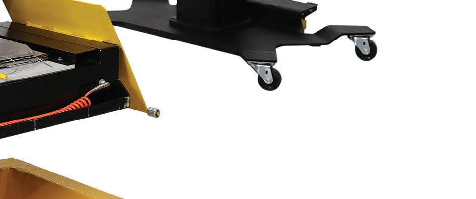
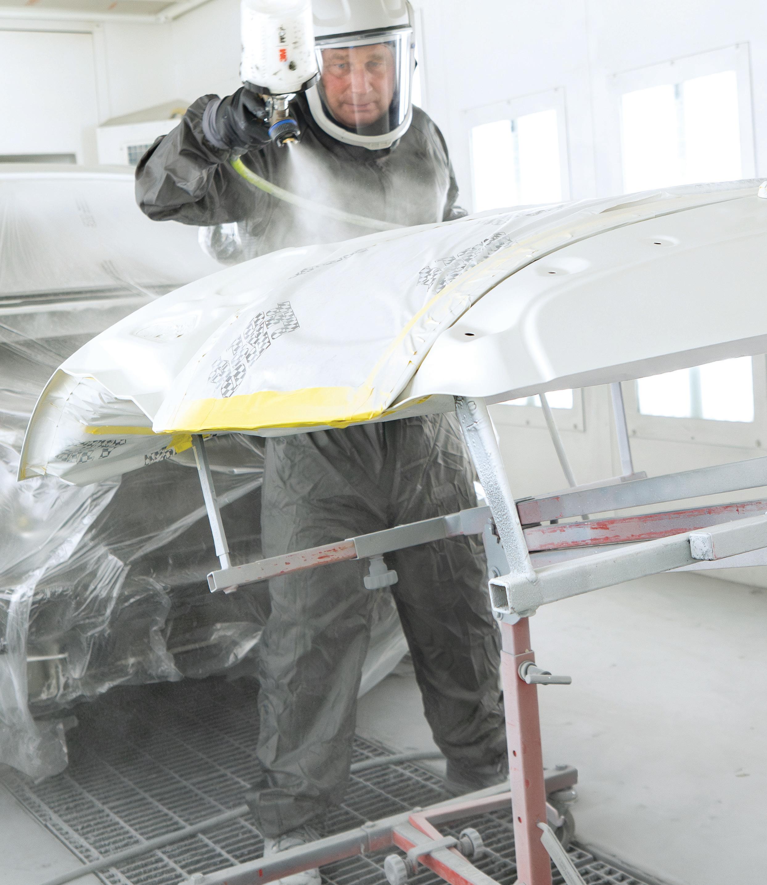
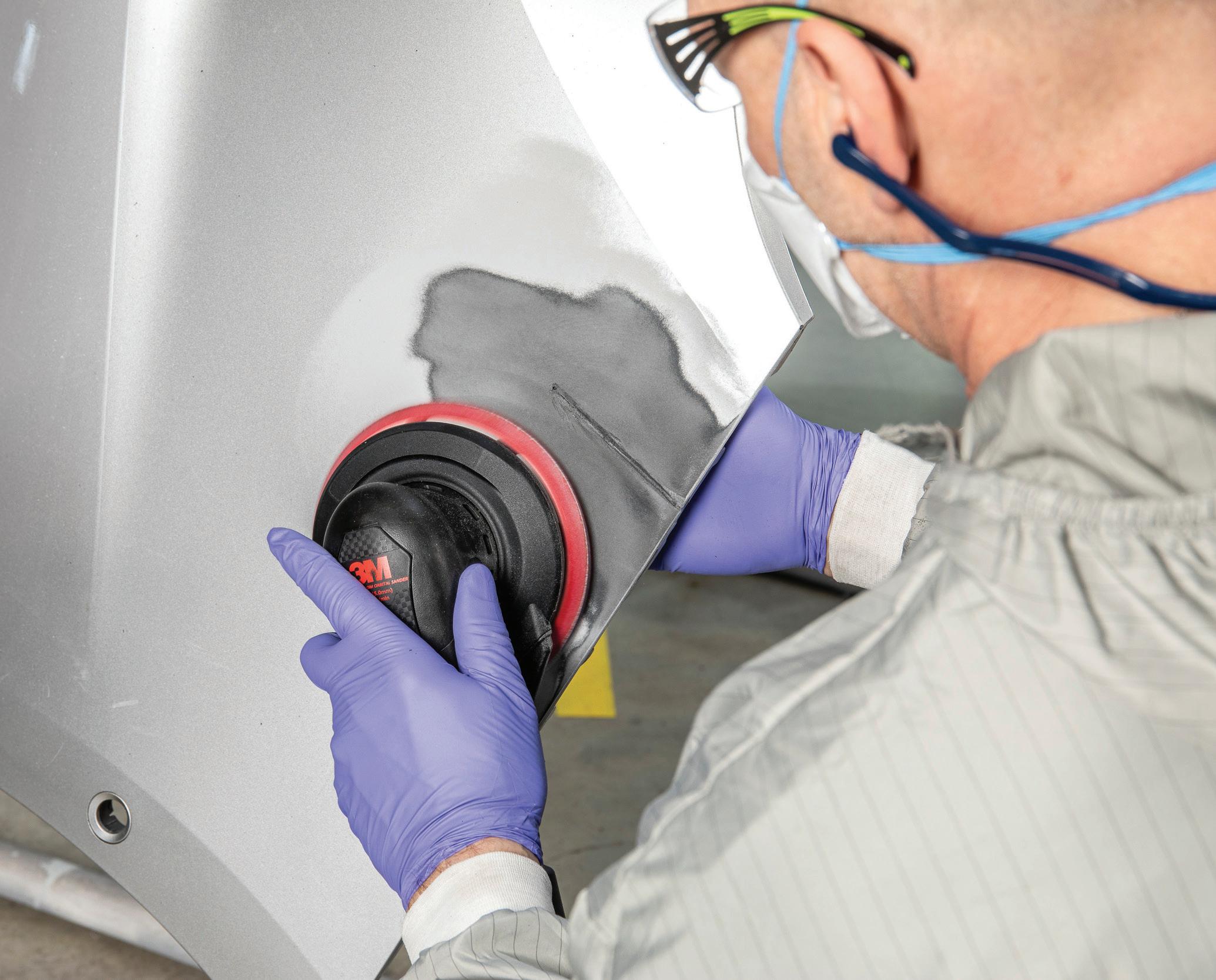
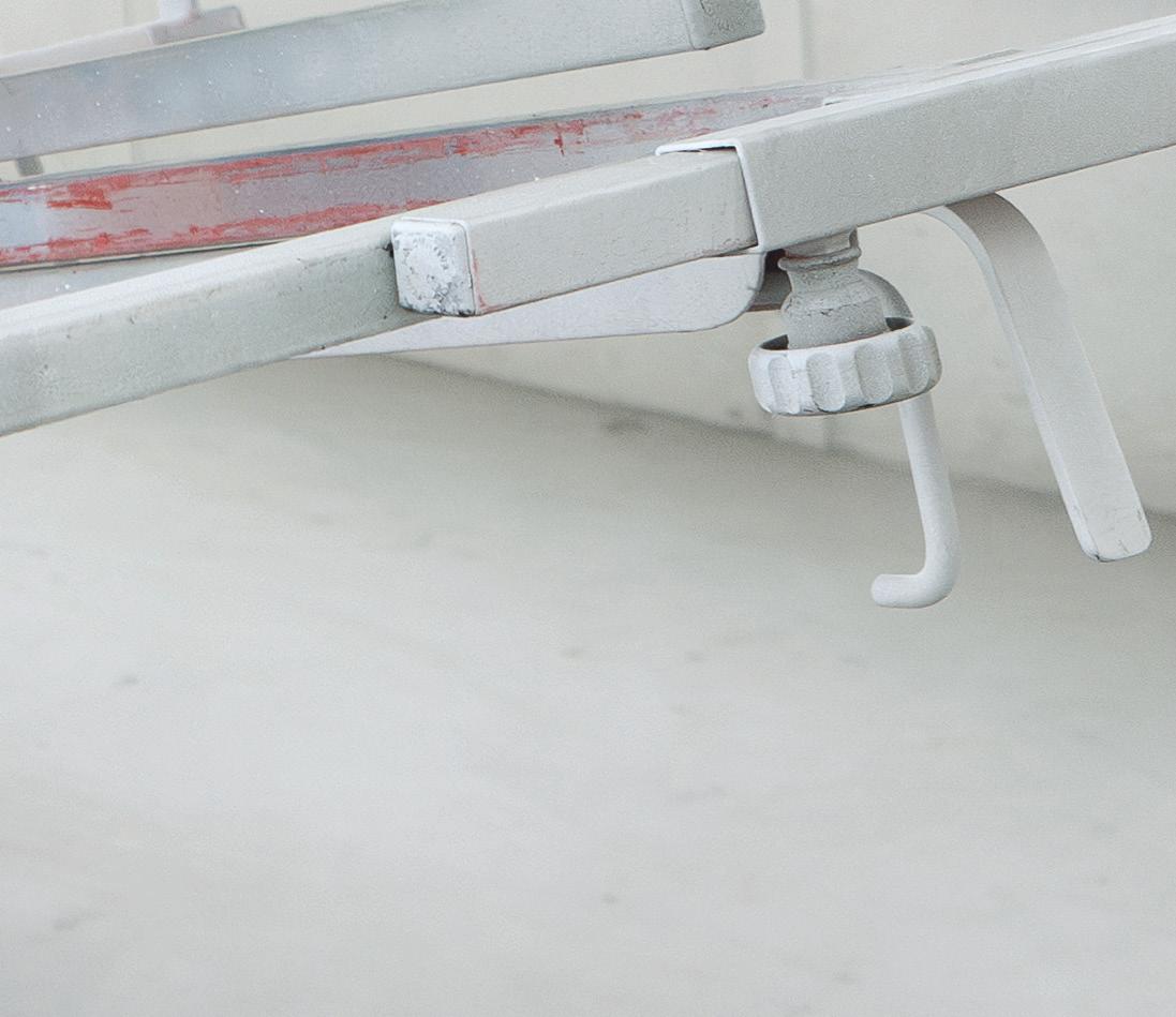
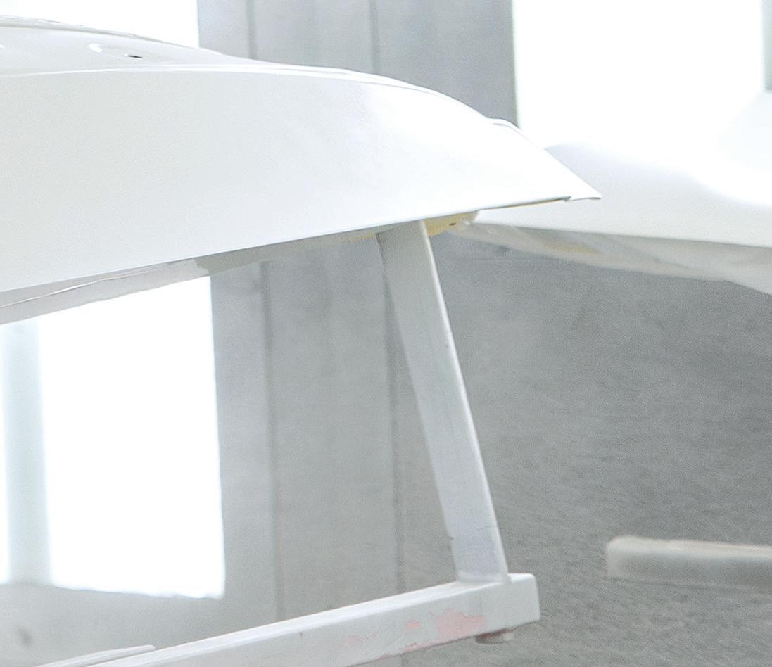
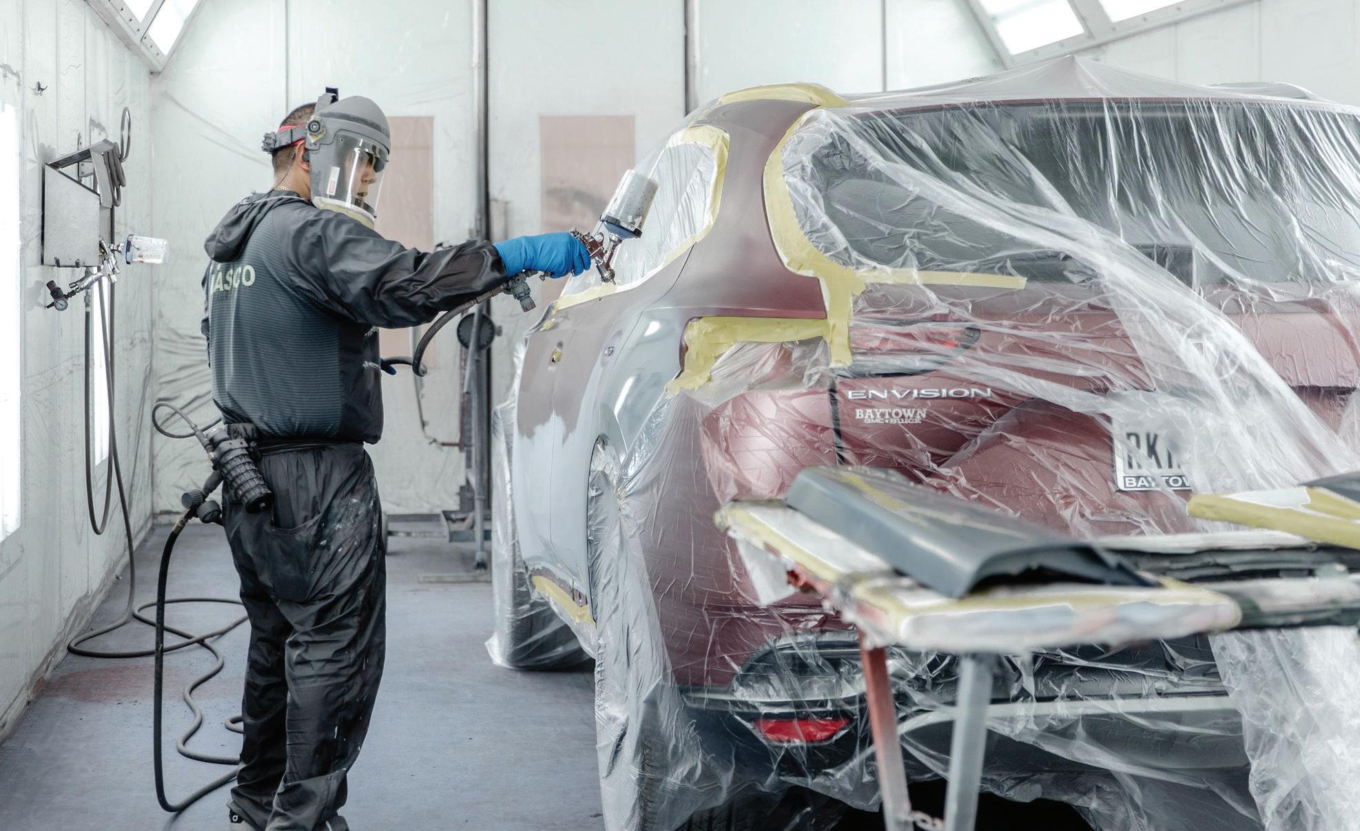
Prep the vehicle entirely
4
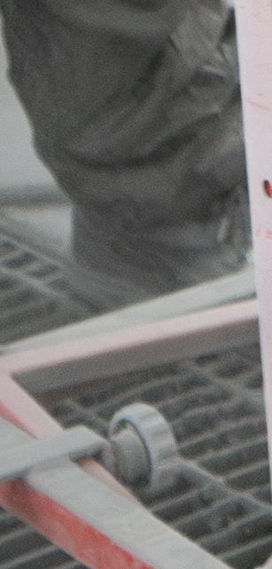
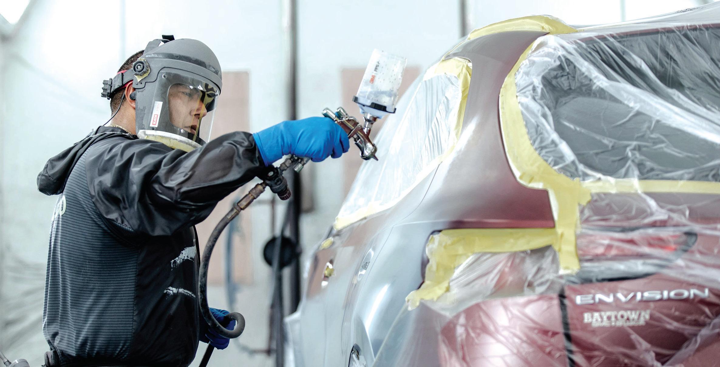
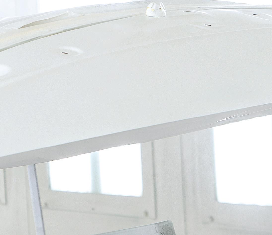
Any operation that can be done prior to entering the booth can contribute to time savings and help with productivity. This means a vehicle should be completely prepped prior to entering the booth, including parts on stands. Ensure the vehicle staged outside the booth is fully outlined with masking tape, leaving the car ready to be brought in booth and covered with plastic sheeting. The parts and the car should get a final wipe of wax-and-grease remover before the paint job can begin. Part of this process includes premixing paint and sealers. Booth time is precious, so ensuring proper vehicle preparation is critical to helping the shop to maximize productivity.
Watch the clock
5
Another best practice to implement is being aware of time and the booth load. Many painters will start a paint job and step away for breaks or even for lunch. But the moment you start the paint process in the booth, you are relying on a chemical bond to ensure proper adhesion. The paint job until now has relied on mechanical adhesion through a sand scratch. We are now relying on a chemical bond, and the process needs to be followed and completed in a timely manner. Additionally, the correct dry times need to be adhered to for proper performance of the product and appearance. Stepping away from the job at hand can result in delays due to the painter becoming distracted, which places the chemical bond window at risk.
Furthermore, stepping away could potentially bring contaminants back into the booth, which may harm the paint job. Grease and food oils from lunches and breaks can really wreak havoc in the booth. Always complete the paint job and use the bake time to prepare for the next job. The time lost by taking breaks outside of a booth bake cycle can’t be made back.
Each step of the collision repair has a process usually outlined with an SOP, and the paint shop has specific SOPs that need to be followed closely. The collision center should review their current process on booth readiness and address as needed. This assessment will help shape the process or processes required to correct booth-readiness. This means removing any steps that slow painters down in the booth to
PREP THE VEHICLE ENTIRELY. The vehicle and parts should be completely prepped prior to entering the booth.
help ensure optimal productivity and efficiency. Both the technician and management can come together to implement the changes needed.
These are steps that highly productive painters use every day to stay organized and productive. While there are many more adjustments that the various departments can make, the implementation of the five listed above is a great place to start. Make a commitment to refine your booth-readiness process and reap the rewards moving forward.
TROY KNOPIK is a lead refinish trainer at 3M Collision’s Skills Development Center. Troy has been in the collision industry for over 35 years. He spent 25 years as a production painter before becoming a paint manufacturer representative for BASF. He trains painters across the country on all aspects of the collision repair process.
SCAN THE QR CODE TO SHARE THIS ARTICLE AND READ RELATED ARTICLES ONLINE
MARIO FIMBREZ, VALLEY OAK DESIGN
TECHNICAL
KEEP IT SIMPLE FOR ADAS DUMMIES
NOT ALL DIAGNOSES TURN OUT TO BE COMPLEX, AS THIS CASE STUDY FOR A BLIND SPOT MODULE SHOWS.
BY JOHN ANELLO
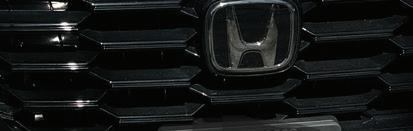
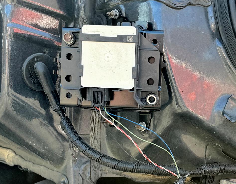
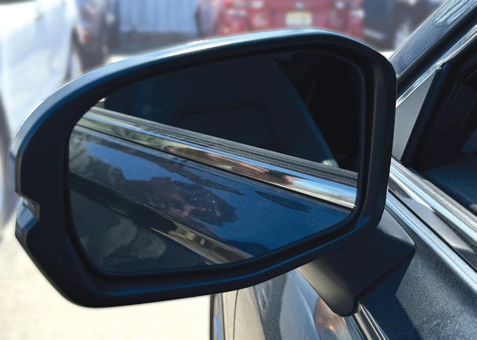
Sometimes, what appears to be a complex issue turns out to be a simple, albeit puzzling, one. I was called to a shop on a 2023 Honda CR-V having an issue with a blind spot monitoring system (Figure 1). e vehicle was involved in a rear end collision, and the
left rear quarter panel of the vehicle took a direct hit from the accident. e shop had to replace the module because it had minor damage to the housing. Once these modules take a direct hit, there may be liabilities if you decide to reuse them. I have even seen some radar modules on other manufactures that had the labeling “If dropped, dispose,” so it’s a strong indication that the internal circuit may be compromised and may not be able to process data inputs properly. e shop made the right choice to replace the module but there were issues with the new module creating error codes in the system. e shop decided to call me in for a possible reprogramming of the new module or to see if there were some underlying issues with the rear body harness he had overlooked.
Prior to arriving there, I made sure the rear bumper of the vehicle was left off so I could inspect the rear body harness, if needed. This tactic could save a lot of time, considering the removal process of some bumpers may get a little involved. I did not want to waste most of my diagnostic time helping the shop remove the bumper while I was there.
Scan to assess vehicle system health
When I arrived at the shop, I performed a full vehicle scan on the car to get an overview of the vehicle just to make sure
FIGURE 1: Honda CR-V that wouldn’t communicate for its blind spot monitor system.
JOHN ANELLO
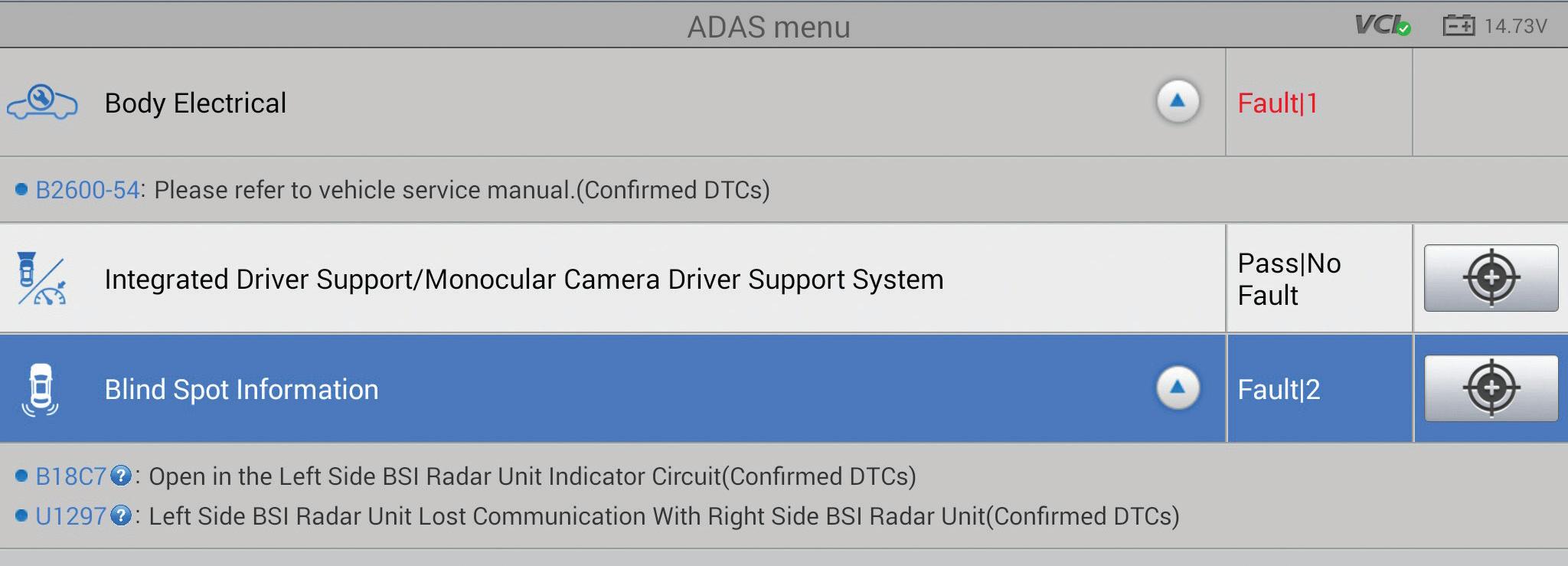
there were not any other underlying issues in the ADAS network and to validate that I could communicate with each rear blind spot control module. The left blind spot module had two current codes in memory, while the right-side blind spot module had no codes in memory. The first code was a B18C7 for an open in the left-side blind spot indicator circuit. The second code was a U1297 for the left-side blind spot module losing communication with the right-side blind spot module (Figure 2).
I pulled the wire conduit and black tape back a little to do a visual inspection on the harness. Without a diagram, I was able to guesstimate the role of most of these wires using my experience of doing so many blind spot modules. There
is that old saying, “You don’t know what you don’t know.” If you can identify within these circuits what you definitely know, then the rest is what you don’t know. At this point, you are going to need a diagram to figure out the unknown. I knew the twisted red and white wires were the CAN network lines, the black wire was most likely a ground, but the light green and the light blue wires had to be power feed and the indicator circuit feeding back to the blind spot bulb for the side mirror (Figure 3).
Consult a wiring diagram to confirm functions
At this point, I did not want to ground the wrong wire to illuminate the indicator bulb because there was a chance
2: The left blind spot module had two current codes in memory, while the right-side blind spot module had no codes in memory.
AMERICAN HONDA MOTOR CO.
FIGURE
JOHN ANELLO
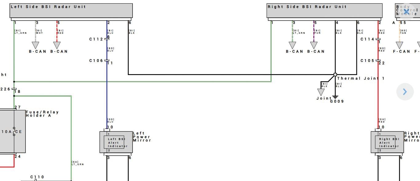
3: The author printed out a wiring diagram from AllData to provide an overview of the electrical system.
of blowing the fuse that fed the blind spot module. I went to AllData to print out the wiring diagram, which gave me a good overview of the system to properly perform my testing on the harness connector (Figure 4). I now knew for sure that the light green wire on pin #1 was the power source for both blind spot modules and the light blue wire on pin #2 was the indicator circuit leading back to the side mirror indicator light bulb.
You CAN do it
I unplugged the new blind spot module and proceeded to check the wiring with my Power Probe. The two CAN lines showed proper voltage, so I knew that the CAN lines were neither shorted nor open. They were within 0.2-0.3 volts of each other, the ground was at about 100 millivolts, and the power feed was at about 12 volts. But the indicator circuit was an open circuit because there should have been a 12volt reading feeding back from the indicator bulb. As this car was new, I felt the problem had to be somewhere in the
rear harness. But I wanted to move forward on the CAN network issue because it posed a larger problem. The shop’s technician had told me that he felt that maybe the new part was bad, so he swapped the parts side-to-side. But now, the same error codes moved to the right side of the vehicle, with codes for the right blind spot indicator open circuit and the right-side blind spot module not communicating with the left blind spot module.
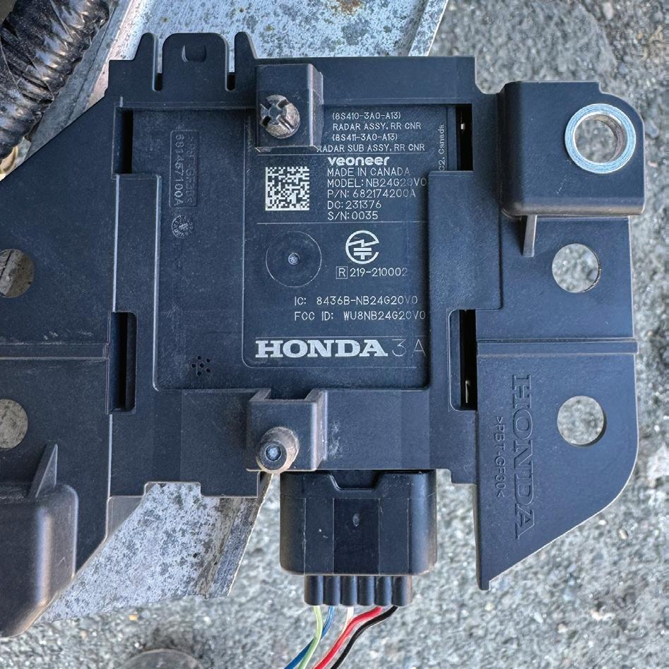
For the replacement module, ensure the part number, connector pin configurations, and mounting match.
This whole situation seemed very odd, so we took both parts out and flipped them over to compare part numbers for a possible changed part number that was not compatible, or maybe they are required to be changed in pairs. The new module on the left side of the vehicle had a part number of 682174200A (Figure 5), but the one on the right side of the vehicle had a part number of 682677200A, which was a totally different number altogether.
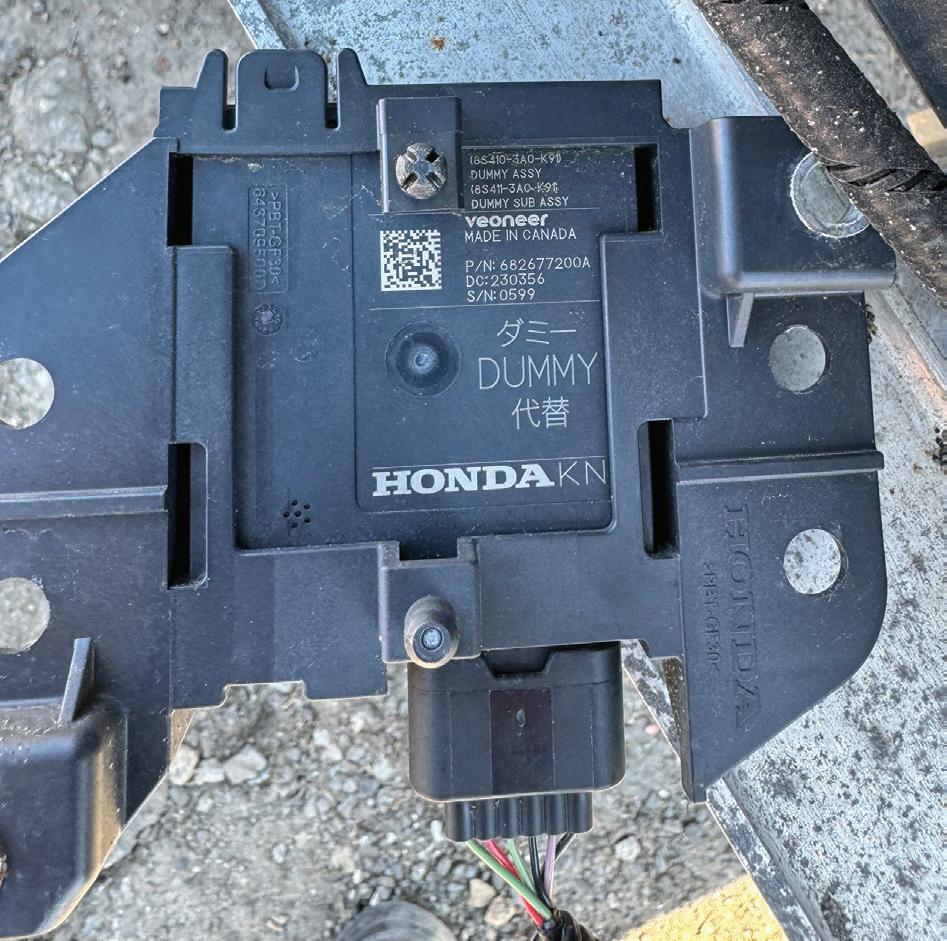
Finding the DUMMY
After a close inspection of the right-side part number, something caught the eyes of the owner of the body shop and me. We saw the word “DUMMY” stamped on the right blind spot module that the new part was not stamped with (Figure 6). This right-side blind spot module was just a placeholder and only served to seal off the connector to keep out moisture. It also would not interact with the ADAS system because this particular car never came with the blind spot module
FIGURE 4: The AllData wiring diagram allowed the author to properly test the harness connector for the blind spot module.
FIGURE
option. When the new non-dummy module was installed on the left side of the vehicle, it woke up the system and put a blind spot error on the instrument cluster. To add to this further, there were no blind spot indicators in the side mirrors (Figure 7). This was why the new module would set an Indicator code for either side in conjunction with setting a CAN network code when it was plugged in. So, the only fix was to buy another dummy.
What an unbelievable situation to happen in the industry, all because the shop was given the wrong module! The part was ordered by VIN, but somehow the blind spot option question was overlooked. It makes you wonder why a manufacturer would not just use a dummy plug instead to avoid all
this “rabbit hole journey” and confusion that I’m sure other shops will fall into. It all goes back to my old-school teachings from watching Sesame Street when I was a little kid, singing “One of These Things is Not Like the Others.” It is so important today to really take the time to compare new parts with the old ones. Make sure you’re not handed the wrong part that could waste a lot of your cycle time in getting these jobs out the door. Keep it simple by performing a visual inspection to make sure the part number is the same, connector pin configurations look identical and in order, and even the mounting looks the same. The parts guy may even tell you that there’s been a changed part number, but it’s up to you to do the final evaluation. I’m hoping that this story hits home with a lot of you auto body techs out there, and all I can say is, “buyer beware.”
JOHN ANELLO is the owner and operator of Auto Tech on Wheels, established in 1991 in northern New Jersey. He provides technical assistance and remote reprogramming with 21 factory PC-based scan tools. Driven by a passion for cars, John’s business now services roughly 1,700 shops.
SCAN THE QR CODE TO SHARE THIS ARTICLE AND READ RELATED ARTICLES ONLINE
FIGURE 5: The new module on the left side of the vehicle had a part number of 682174200A.
FIGURE 6: The OEM module on the right side of the vehicle had a part number of 682677200A. But look closely and see this is a nonfunctional “dummy” unit.
FIGURE 7: There is no blind spot indicator in the OEM mirror.
JOHN ANELLO
JOHN ANELLO
JOHN ANELLO
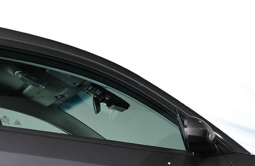
EMPOWERING TECHNICIANS: LESSONS LEARNED FROM AN AUDI ADAS CALIBRATION
HOW EFFECTIVE MENTORING RESOLVED A TRICKY LANE-CHANGE
ASSIST CALIBRATION ISSUE ON A 2019 AUDI TTS.
BY PAUL BOSTEL
Advanced driver assistance systems (ADAS) have transformed the automotive repair landscape, introducing an era in which calibration, diagnostics, and electronic troubleshooting skills are more critical than ever. Shops nationwide are adapting quickly, but even the most experienced technicians can encounter challenges when working on these sophisticated systems. Recently at our facility, we faced an intriguing challenge involving a 2019 Audi TTS equipped with lane-change assist, providing an opportunity to highlight e ective technician mentorship and the diagnostic mindset needed in modern auto repair.
Encountering the Problem
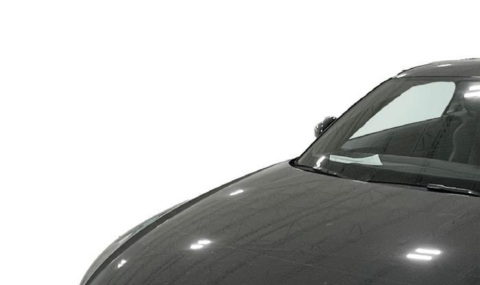
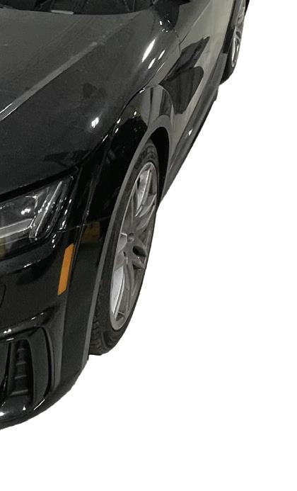
The 2019 Audi TTS’ lane-change assist could not be calibrated until the communication problem was resolved.
Our story begins with a seemingly straightforward task. A 2019 Audi TTS entered our shop needing its lane-change assist system calibrated after collision repairs. The lane-change assist is part of Audi’s ADAS suite, which uses radar sensors to monitor adjacent lanes and alert drivers of potential hazards during lane-changing maneuvers. While routine calibrations usually proceed smoothly, this vehicle soon presented with an unexpected complication.
PAUL BOSTEL
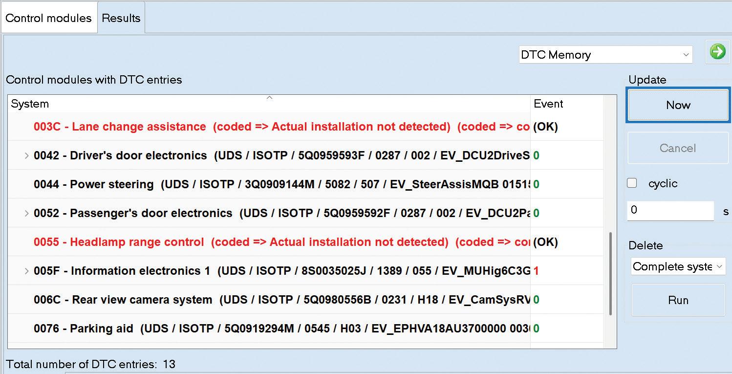
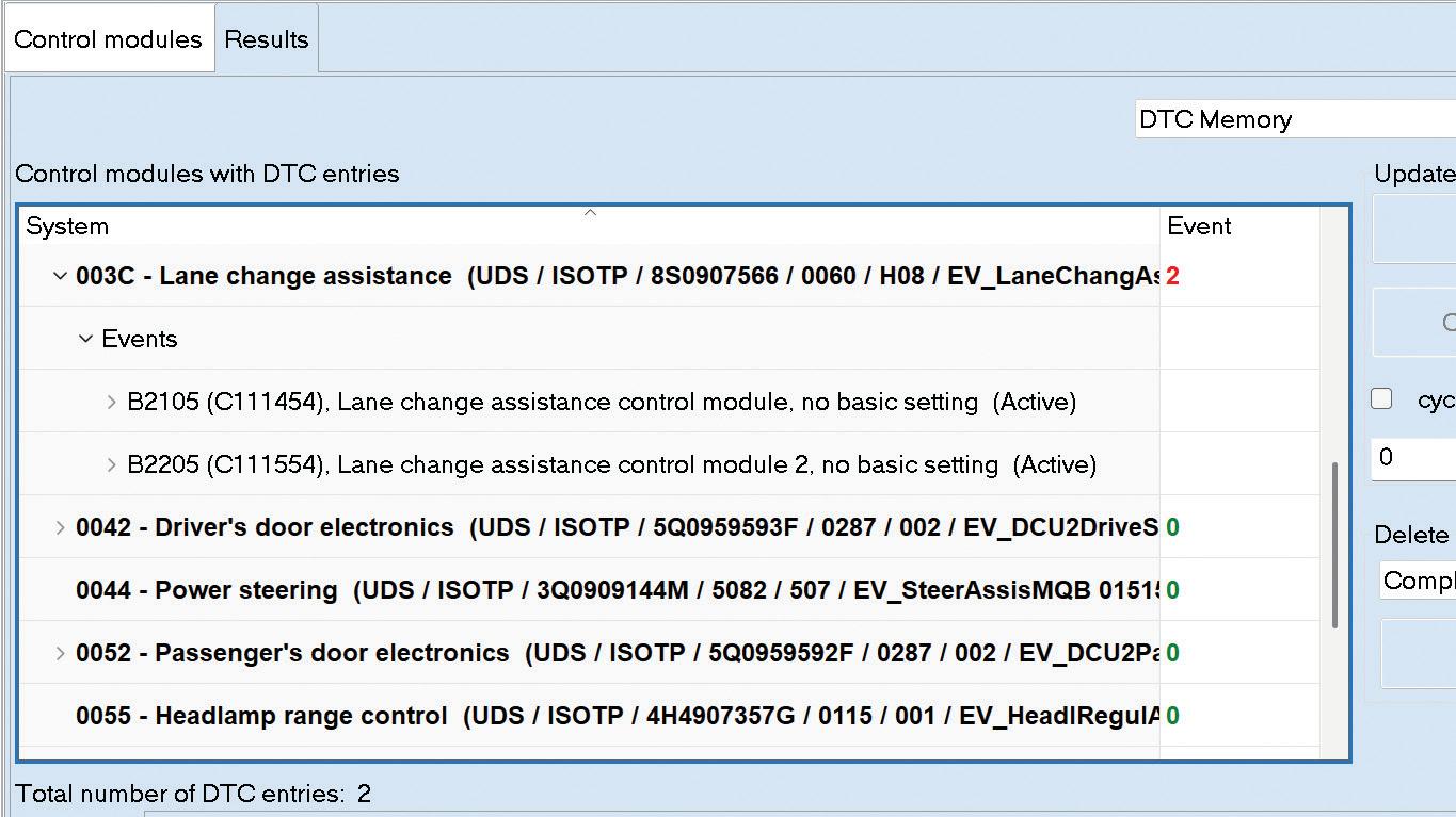
The job was initially assigned to one of our junior technicians who has been with our team for approximately three years. During his tenure, this technician has consistently demonstrated skill progression, confidence, and a commendable eagerness to tackle increasingly complex diagnostic tasks. His initial approach to this calibration was routine until he encountered a persistent communication error in the lane-change assist system. Installation of the system was not detected (Figure 1), which prevented his ability to perform a calibration of the system.
Diagnostic Process and Hypothesis
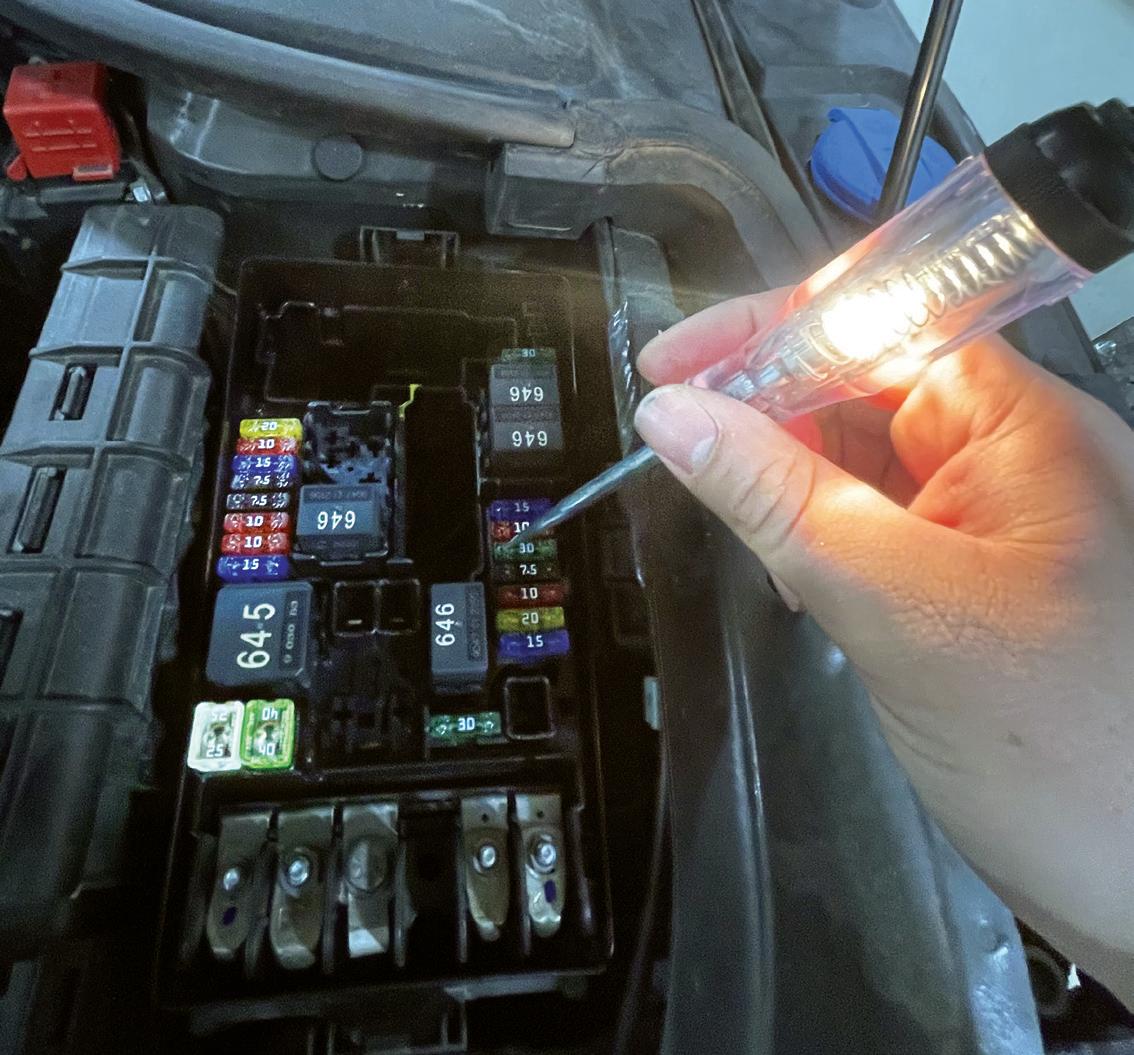
In our shop, we emphasize approaching diagnostics with a systematic strategy. So, our technician transitioned from calibration to diagnostics and began with foundational checks. First, he confirmed the work that was performed to the vehicle and then removed the bumper to visually confirm all modules were properly connected and secured. He then proceeded to verify the system’s fuses were intact and fully functional (Figure 2).
After completing these initial steps, the technician developed a hypothesis. Because the vehicle had recently undergone repairs in which the driver-side lane-change assist module was replaced and the passenger-side lanechange assist module was retained, he suspected a version mismatch between these two modules could be the root of the issue. This seemed logical based on his past experiences with other brands and how the problem was presenting in the Audi.
The Importance of Mentorship
Feeling confident in his assessment, the technician approached me to discuss his findings. This interaction un-
derscores the critical role mentorship plays within the automotive repair industry, particularly when it concerns diagnostics. As an experienced technician myself, I’ve witnessed firsthand the complexities of ADAS system diagnostics. I recalled dealing with a similar Audi lane-change assist issue a few years ago, one that mirrored the symptoms my technician currently faced.
While the technician’s hypothesis was well-founded based on his experiences, his conclusions hadn’t fully convinced me. Because I had experienced a similar issue, I recognized the need to thoroughly investigate to confirm
FIGURE 1: This screenshot shows the initial vehicle scan.
FIGURE 2: A quick check of the lane-change assist system fuse showed it was functional.
the root cause of the problem. This was a prime mentorship moment: balancing encouragement of independent problem-solving skills while gently guiding the technician toward more comprehensive diagnostic methods.
I advised my technician to delve more deeply into verifying power, ground, and communication signals at the modules. My previous experience underscored how critical thorough electrical checks can be in isolating elusive diagnostic issues. Although initially hesitant, he accepted the guidance and returned to the Audi TTS with a renewed focus, now better prepared to resolve the issue with greater confidence.
Discovery and Resolution
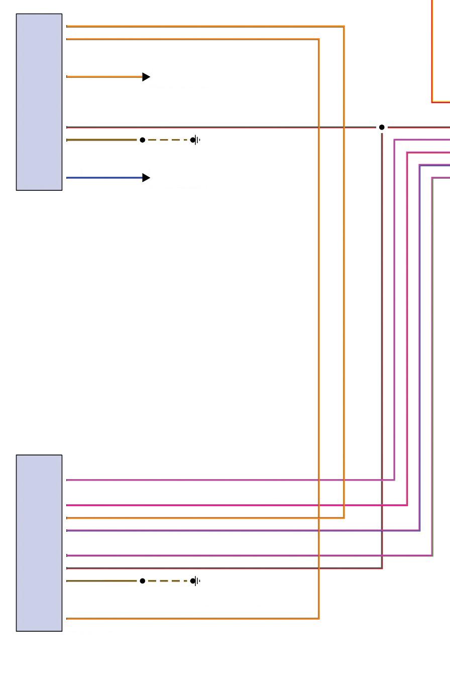
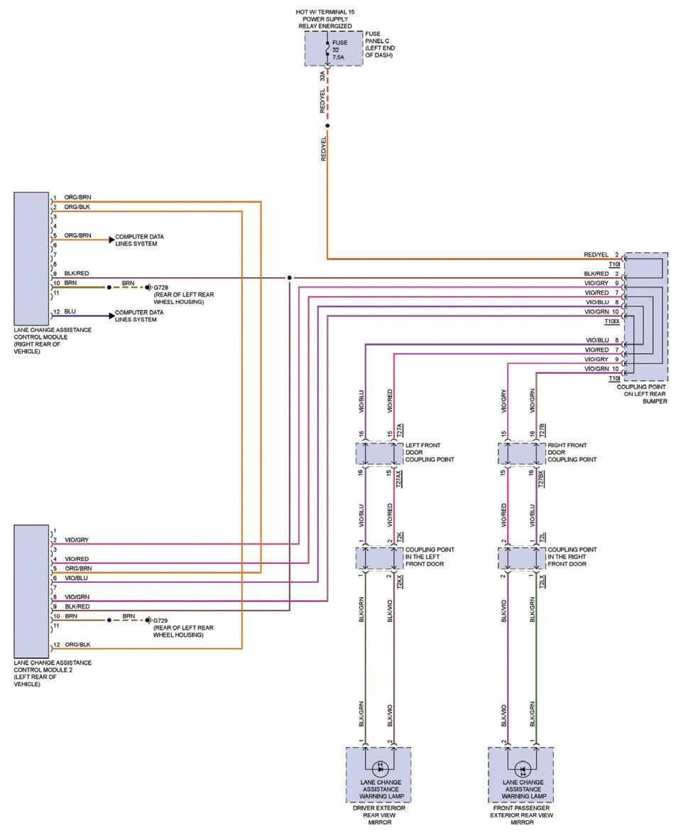
Armed with wiring diagrams (Figure 3) and a sense of clarity, the technician began to methodically identify the circuits that would need to be tested. His first important discovery was that the connector wires at the lane-changeassist module didn’t match the pin positions
indicated in Audi’s technical resources. His realization signaled that something deeper than a version mismatch between modules might be at play.
Spurred by this unexpected finding, he carefully inspected the vehicle’s wiring harness and related connectors. This
FIGURE 3: This Mitchell 1 wiring diagram shows the lane-change assist circuit.
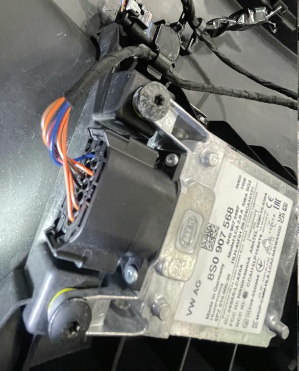
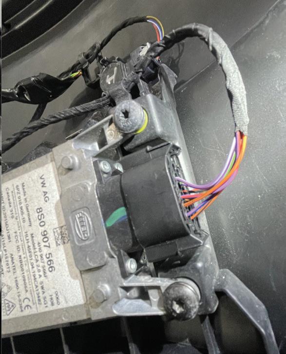
FIGURE 4: The collision repair technician had incorrectly installed the harness at the left and right lane-change assist modules.
proved fruitful almost immediately, as he discovered that the wiring harness in the bumper had been inadvertently installed incorrectly by the collision repair technician. Specifically, the harness had been installed in reverse; the connector for the driver-side module was connected to the passengerside module, and vice versa (Figure 4). This installation error was the root cause of the communication failure.
Once the technician corrected the harness connections, reconnecting each module properly, the lane-change assist system immediately resumed normal communication (Figure 5). With the communication error resolved, he successfully completed programming of the replacement module and calibration of the lane-change assist system, which returned the vehicle’s ADAS to optimal functionality.
Key Takeaways and Conclusions
This experience with the Audi TTS ADAS calibration teaches several valuable lessons. First and foremost, junior technicians should be consistently empowered to take the initiative in complex diagnostics. Encouraging them to form hypotheses, explore possibilities, and confidently approach senior colleagues with their ideas significantly boosts professional growth and independence.
Secondly, the presence of an experienced technician as a mentor can never be understated. While independence is critical, guidance from seasoned professionals ensures junior technicians remain on the right path. Mentorship provides context, practical wisdom, and helps to prevent common or avoidable diagnostic missteps.
Finally, this event reiterated that ADAS issues often appear in unexpected ways, with resolutions not always aligning with initial assumptions. As vehicle technology evolves, technicians must maintain a flexible and thorough approach
FIGURE 5: This screenshot shows the DTCs present after the harness installation error was resolved.
and continually be prepared for surprises. Training our teams to maintain open-mindedness and diligence when facing diagnostics, especially when ADAS is involved, is crucial to delivering quality repairs in a rapidly advancing industry. By fostering environments where junior technicians feel supported yet challenged, we create the next generation of diagnostic experts. Technicians who will confidently navigate the complexities of modern automotive technology. The Audi TTS calibration issue turned into an opportunity for growth, mentorship, and reinforcement of diagnostic best practices.
Paul Bostel is a seasoned leader with a rare blend of expertise in both advanced automotive technology and fire service operations. With over 20 years in the automotive industry, he is recognized as one of fewer than 2,300 ASE World Class-certified technicians — a distinction that underscores his mastery in diagnosing and repairing complex vehicle systems, with a specialized focus on ADAS. Paul currently manages Accelerated Vehicle Technology in Bloomington, Minnesota, a Quality Collision Group brand, where he applies his analytical precision and strategic mindset to elevate operational performance and repair standards. In parallel with his automotive career, Paul has proudly served the Apple Valley Fire Department for over nine years and holds the rank of captain, demonstrating his strong leadership, commitment to community service, and ability to manage high-pressure environments. His career is defined by innovation, efficiency, and a continuous drive to raise industry standards across every role he takes on.
SCAN THE QR CODE TO SHARE THIS ARTICLE AND READ RELATED ARTICLES ONLINE
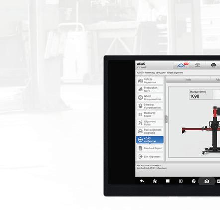
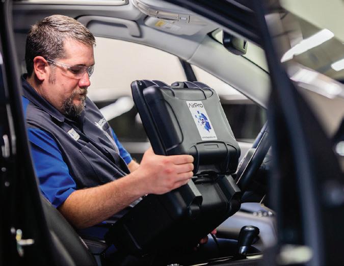
Collision shops must diagnose vehicles quickly and accurately. Modern vehicles include advanced driver assistance systems (ADAS) that require precise calibration. Without real-time support, technicians may misdiagnose issues, replace the wrong parts, and extend repair time.
AirPro Diagnostics provides real-time remote diagnostics, giving shops immediate access to expert Brand Specialists. Eliminating guesswork ensures accurate assessments without unnecessary delays.
The Problem: Inaccurate Diagnoses and Slow Repairs
Many shops rely on traditional methods for diagnosing vehicle issues. This can lead to:
• Unnecessary part replacements –Misdiagnosis = wasted resources
• Longer cycle times – Trial-and-error troubleshooting = repair delays
• Inconsistent accuracy – Without real-time expert input, some issues could go undetected
As vehicles become more advanced, traditional diagnostic methods no longer meet industry standards. Businesses must adopt real-time solutions to remain efficient.
The Solution: Real-Time Remote Diagnostics
AirPro Diagnostics eliminates guesswork by providing real-time remote Brand Specialists. The technicians can access vehicle scanning results and provide accurate recommendations. This prevents unnecessary part replacements and reduces cycle time, increasing customer satisfaction.
Key Benefits for Collision Shops
• Faster Diagnostics: Reduce down time with real-time assessments
• Accurate Results: No unnecessary repairs improve first-time fix rates
• Detailed reporting: Remove the guess work
• Cost Savings: Minimize wasted labor and incorrect fixes
• AirPro provides manufacturer supporting documentation, saving time by doing the research for you
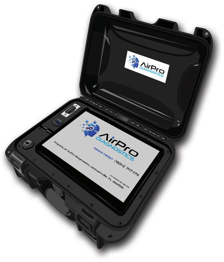
Experience the AirPro Diagnostics Advantage
Collision shops need fast, accurate, and reliable diagnostics to stay competitive. Traditional methods create delays and increase costs. AirPro Diagnostics removes uncertainty, helping shops complete repairs with confidence. With realtime remote diagnostics, shops can reduce cycle time, eliminate unnecessary expenses, and improve customer satisfaction.
AirPro Diagnostics provides the tools and expert support your shop needs to diagnose and repair vehicles confidently, ensuring complete and safe repairs.
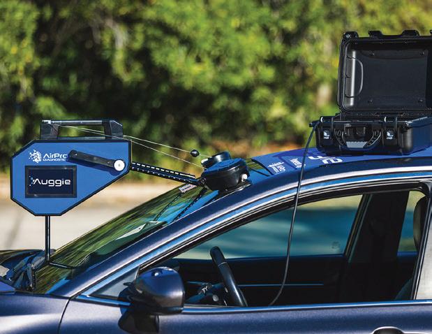
Invest in AirPro Diagnostics’ advanced remote diagnostics tool and FFC calibration system to elevate your business and experience the advantage only AirPro Diagnostics can provide.
11737 Central Pkwy Jacksonville, Fl 32224 (904) 717-1711
ADVERTORIAL
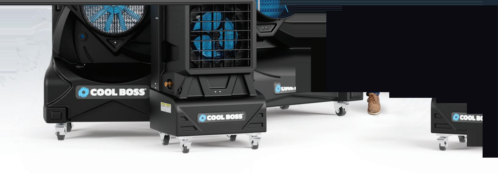
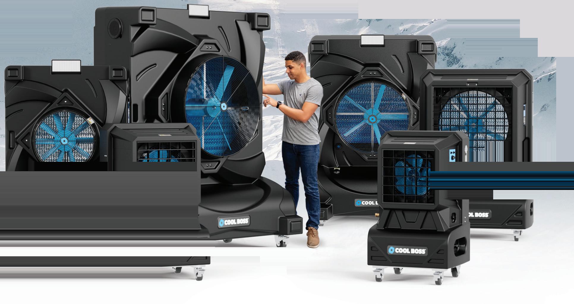
Keep Your Cool on the Job
It’s easier to warm up than to cool o , especially if you’re toiling in a broiling shop. And when summer sends the temperatures soaring, your productivity can take a nose-dive. When things get that hot and heavy, you might long to be an old-time mechanic working under the proverbial shade tree.
A leafy canopy tall enough to cast a shadow over your work area would be lovely, but trees don’t grow overnight, and they don’t force cool breezes indoors. High-school physics tells us it’s not about blowing air around anyway.
What cools you off is evaporating moisture from the air before a fan flows it at you. That’s the principle behind portable evaporative air coolers. Running these units where needed can blow hot summer conditions right out of a shop — and even cool outdoor work areas. They’re the surefire way to work coolly and comfortably despite high temperatures.
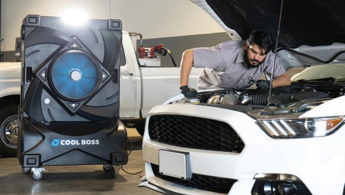
Better than A/C
While air conditioning is expensive and impractical for many shops, let alone outdoor bays, evaporative air coolers are cost-e ective, mobile, and begin cooling the air as soon as they are switched on.
ey’re extremely versatile as they come in a range of sizes and con gurations to match the cooling needed in nearly any work area. Fan-driven, evaporative coolers blow chilled air across a shop; plugging in multiple coolers amplifies the cool-down e ect as needed.
As their name suggests, portable evaporative air coolers work through evaporation. Plug one into a standard 110V electrical outlet, fill its reservoir with water, or connect it to a garden hose for auto-filling, then turn it on and prepare to chill out.
Evaporative coolers use purposebuilt fan blades to draw in hot air through the back of the unit and blast out chilled air through the front. Their fans are designed to pull in more air at low RPMs for peak performance.
Inside the cooler
Within the cooler, air is moved through special evaporative media pads. These soak up cool water like a sponge, acting like a pre-chiller for the incoming air. When the hot air passes through these pads, the water evaporates and instantly drops the air temperature by up to 26°F. is is all achieved without the expensive high‐amp compressor motors, environmentally toxic chemicals, and refrigerants required by air conditioning systems.
Some coolers offer various convenience features, such as a negative air ionizer to help clean the chilled air, outdoor-rated adjustable floodlights, LED control panels, remote control, and
even built-in Bluetooth® audio players and stereo speakers.
Keep in mind that keeping cool on the job is about more than getting more done on a hot day.
The issue is that no one works as well in hot situations. As a result, productivity dips, morale may suffer, and mistakes may be made. That’s why OSHA mandates that employers protect workers from extreme heat.
So, don’t sweat it. Just add water and plug in your portable evaporative air coolers for near-instant relief from furnace-like heat.
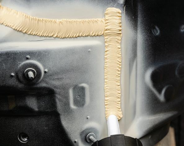
OEM MATCH MADE EASY
Help save time and effort with the 3M OEM Match Family of seam sealer solutions. The 3M OEM Match Family of seam sealing products is engineered to help technicians of all skill levels more easily replicate the appearance and function of a vehicle’s original factory seam sealer. The system includes 3M’s line of seam sealer matching tips and the 2K 3M OEM Match Epoxy Seam Sealer in four colors, allowing you to replicate the most common OEM seams with one simple application. Whether you are a novice or seasoned expert, the 3M OEM Match Family is designed to make replicating OEM seam sealer easy.
FENDERBENDER.COM/55285651
SPONSORED
COLLISION PRODUCT GUIDE
VIBRATION CONTROL REDUCES FATIGUE
The 24V Random Orbital Polisher, No. FX3321, from FLEX Power Tools, is a cordless polisher that removes material with constant speed technology that can maintain high rpm under pressure, delivering up to 4,350 rpm and 8,700 opm. Its optimized gear head reduces high-frequency noise and vibration control reduces fatigue. This 24V battery-powered random orbital polisher features a lightweight body with an ergonomic grip plus an 11-speed control dial with a variable speed trigger for ultimate control.
FENDERBENDER.COM/55285471
COLLISION PRODUCT GUIDE
FOR SHOWROOM-QUALITY RESULTS
REACH IN TIGHT SPACES
Valentine Performance Detailing offers a curated selection of Professional-grade Polishing Compounds and Pads — perfect for cutting through defects or refining the final finish for commercial-level results across every paint type and surface. Polishing solutions include highdensity foam pads in a variety of sizes and strengths from ultra soft to firm, as well as low lint lambswool orbital detailing pads, glass polishing and microfiber cutting pads. VPD also features best-in-class polish formulations designed to deliver showroom-quality resultsw every time: Ultra-Cut HeavyDuty Cutting Compound; Ultra-Refine Medium Polishing Compound; Ultra-Finish Fine Polishing Compound.
FENDERBENDER.COM/55285665
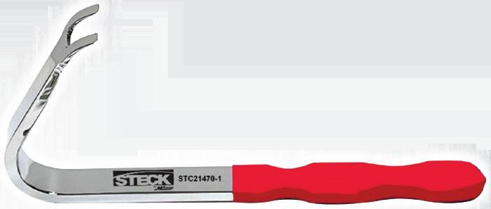
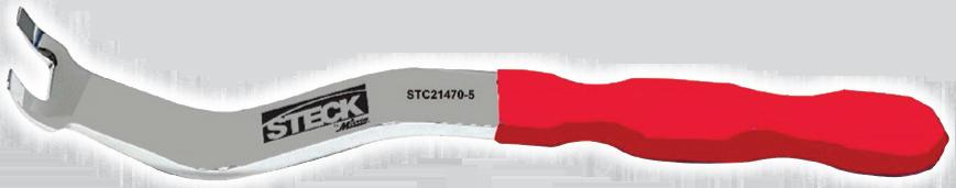
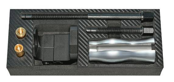
INCLUDES SPRING-LOADED PULLER
The Mueller-Kueps Universal Wiper Arm Puller Kit, No. 650 370, makes the removal of wiper arms quick and easy. It features a long spindle and slotted slide weight that can be used as a mini slide hammer, making it ideal for stubborn cone seat
connections. The kit also includes a spring-loaded puller that allows for instant adjustments and a small sleeve to protect the sprayer when removing a rear wiper arm.
FENDERBENDER.COM/55285457
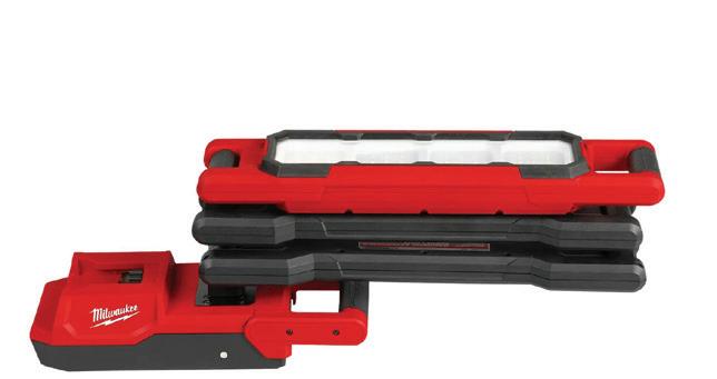
The Milwaukee Tool M18 Magnetic Extendable Boom Light, No. 2129-20, features two articulating arms and three swivel points with 900 degrees of vertical rotation and 890 degrees of horizontal rotation. Combined with the light’s strong magnetic base, it can provide reach in tight or awkward spaces. The base also has a release mechanism for easy removal and replacement as well as a protective storage boot that reduces the magnet strength for safe toolbox storage. The light offers 2,500 lm for up to 12 hours on low or 4.5 hours on high on one M18 XC5.0 battery. It has an IP54 rating for dust and water resistance, is impact-rated, and is corrosion-resistant. The light comes with a 5-year warranty.
FENDERBENDER.COM/55285494
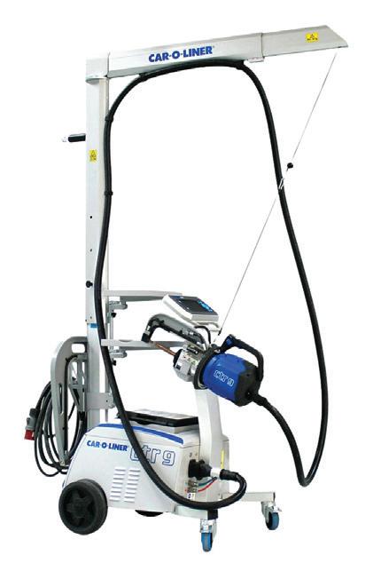
LIGHTWEIGHT AND ERGONOMIC GUN
The Car-O-Liner CTR 9 Resistance Spot Welder is fully automatic and features a lightweight transformer gun with a 355-degree swivel handle and ergonomic grip. The gun is supported by a telescopic arm made from extruded aluminum that can be adjusted vertically and horizontally. The welder uses a compact power unit with a low center of gravity for maneuverability and stability, and its 16,000 amp transformer and CAN bus communication ensure quality welds. The CTR 9 offers a 20L tank capacity, 1000W of cooling power, and a rated cooling liquid flow of 3L/min.
FENDERBENDER.COM/55285482
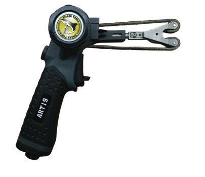
STREAMLINES SPOT WELD PREPARATION
The Killer Tools Spot Weld Pro, No. ART19, is a patented new professional surface prep tool designed to streamline spot weld preparation. Featuring a powerful 0.6HP pneumatic motor and dual cleaning heads, the ART19 aligns and strips paint from both the inner and outer panel flanges, boosting productivity and ensuring clean, accurate welds. Ideal for body shops, it removes material only where needed for spot welds. The cleaning arm features an adjustable angle and includes three Italian-designed 18” by 1/2” fiber belts, with replacement belts, No. ART19-BM, available separately.