The Ultimate Lift Showdown
BendPak ASARS System delivers 360-degree arm restraint across all two-post lifts, supporting EV-Ready safely and unmatched lift stability.
The Test
Automatic Swing Arm Restraint System


BendPak ASARS System delivers 360-degree arm restraint across all two-post lifts, supporting EV-Ready safely and unmatched lift stability.
The Test
Automatic Swing Arm Restraint System
TheAPtwo-postliftoffersexceptionaldirect-driveliftingperformance.Thisindustrial-strengthcarliftguarantees cutting-edgetechnology,topofthelinematerials,adesignthat’saheadofitstimeanda10,000-lb.liftingcapacity.
Features Automatic Swing Arm Restraint System for added Safety.


Thisisourstandardmodel thatfeatures73"oflifting heightandanoverhead beamheightofjust145"for shopswithlowerceiling clearances.
Columnextension adds24"ofadditional under-clearance heightforEuro-style cargovans

Thismodelfeaturesanupper crossbarthat’spositionedtwo feethighertoaccommodate highroofcargovans.Features 73"ofliftingheightandan overheadbeamheightof168".
TakevehicleservicetothenextlevelwiththeProSeries. EachProSeriesliftcomescompletewithitsrespectivelift, setsofadapters,cradlepads,andtheWSA-100air-electric workstation.
10AP PRO #5175639
10AP-168 PRO #5175644
10APX PRO #5175648
10APX-168 PRO #5175649

Pads


Tallertechniciansare sometimesatadisadvantage whileworkingundera standard-riselift.This high-risemodelfeatures 79.5"ofliftingheightandan overheadbeamheightof
Columnextension adds24"of additional under-clearance heightforEuro-style

Likeour10APX,thishigh-rise modelalsofeatures79.5"of liftingheight,butitcomeswith anoverheadbeamheightof 181"toaccommodatehighroofcargovans.
Alreadyowna10APlift?Giveittheupgradeitdeserves withanAdapterKit.DeluxeandProPackagescome loadedwithwhatyouneedtoservicemorevehicles thaneverbefore.
DELUXE #5210480 Two-PostLiftAdapter Kit
•FrameCradlePads
•MediumAdapters
PRO #5210481 Two-PostLiftAdapter Kit
•FrameCradlePads
•MediumAdapters
•TallAdapters


Whether you’re a seasoned technician or just starting in the industry, our Gold video library has everything you need to stay ahead of the curve.
Unlock over 60 hours of advanced, in-depth automotive training with our Gold video library. Featuring recorded webinars led by industry experts, this comprehensive library covers cutting-edge diagnostics, complex repair techniques and the latest innovations in automotive technology. With new content added monthly, you’ll stay up-to-date on emerging trends and tools, ensuring your skills remain at the forefront of the industry.
Learn from industry experts through our extensive library of recorded webinars covering essential topics—from advanced diagnostics to the latest automotive technologies. With flexible subscription options, you can access top-tier content when it works best for you.

Subscription benefits
Access to our Free video library
Access to our Gold video library
Webinar handouts
Discounts for live events, including our DTC Annual Event
Swag and other giveaway items Sign up now

04 Online Extras
06 Straight Talk 08 Tech Tips TECHNICAL
10
Searching for a Place to Call Home
“There’s no place like home.” That rings true for automotive technicians, too.
Brandon Steckler
16 Rolling Into Revenue
Connecting tire wear, diagnosis, and shop collaboration
Erik Screeden
24 Piston Ring 101
Tips on ring gapping and rod installation
Mike Mavrigian
36 Achieving a Childhood Dream Cawens Fleurilus is the 2025 Best Young Tech
Alison Johnson
46 Start-Stop Systems
Why they don’t always stop — or start Jeff Taylor
54 Certain Things Trigger Me ECUs are not smart at all. They are only as good as the inputs they rely on.
Brandon Steckler
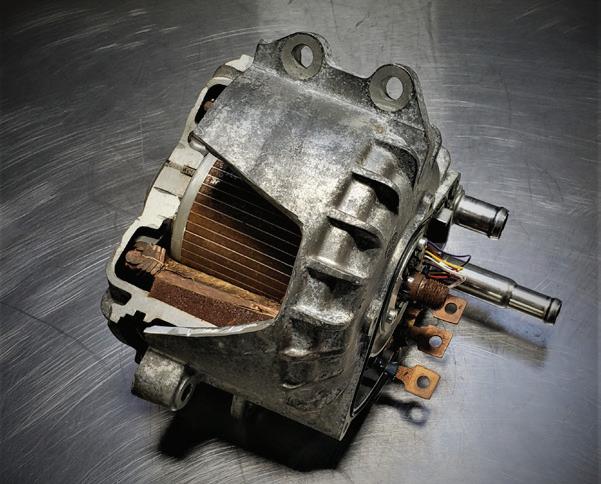
58 xEV Diagnostics and 3-Phase Motor Testing
When it comes to figuring out what is wrong, you must know what is right.
Craig Van Batenburg
74 The Trainer #165 MRE sensors
Brandon Steckler
in the material herein, regardless of whether such errors result from negligence, accident, or any
cause whatsoever. The views and opinions in the articles herein are not to be taken as official expressions of the publishers, unless so stated. The publishers do not warrant either expressly or by implication, the factual accuracy of the articles herein, nor do they so warrant any views or opinions by the authors of said articles.
Endeavor Business Media provides certain customer contact data (such as customers’ names, addresses, phone numbers, and e-mail addresses) to third parties who wish to
services, and other opportunities that may be of interest to you. If you do not want Endeavor Business Media to make your contact information
to third parties for
simply call toll-free 877382-9187 or email MotorAge@omeda.com and a customer service representative will assist you in removing your name from Endeavor Business Media’s lists. Motor Age does not verify any claims or other information appearing in any of the advertisements contained in the publication, and cannot take responsibility for any losses or other damages incurred by readers in reliance of such content. While every precaution is taken to ensure the accuracy of the ad index, its correctness cannot be guaranteed, and the publisher waives all responsibility for errors and omissions
EDITORIAL
GROUP EDITORIAL DIRECTOR
Chris Jones / christopherj@endeavorb2b.com
EDITOR Mike Mavrigian / mmavrigian@endeavorb2b.com
MANAGING EDITOR
Joy Kopcha / jkopcha@endeavorb2b.com
TECHNICAL AND MULTIMEDIA CONTENT DIRECTOR
Erik Screeden / escreeden@endeavorb2b.com
TECHNICAL EDITOR
Brandon Steckler / bsteckler@endeavorb2b.com
ASSOCIATE EDITOR
Madison (Gehring) Hartline / mgehring@endeavorb2b.com
CONTRIBUTING WRITERS
Jeff Taylor, Craig Van Batenburg
ART AND PRODUCTION
ART DIRECTOR
Emme Osmonson

We know it can be hard to find time to study or go to trainings to advance your skills. We fully endorse doing so of course, but we understand how the daily grind makes it difficult. That’s why we’re adapting more technical tips and tricks into short form videos and sharing them on YouTube, as well as on Instagram. Be sure to follow along.

SCAN THIS QR CODE TO FOLLOW US ON INSTAGRAM!
Are you mystified by refrigerants, HVAC work, and what’s changing? We’ve added to our library of content on R-1234yf and R-444A and the tools and equipment needed to do the job with the help of Orbia Fluor & Energy Materials. Check out the latest article on VehicleServicePros.com.
PRODUCTION MANAGER
Mariah Straub
AD SERVICES MANAGER
Karen Runion
SALES
ASSOCIATE SALES DIRECTOR
Mattie Gorman-Greuel / mgorman@endeavorb2b.com
DIRECTOR OF BUSINESS DEVELOPMENT
Cortni Jones / cjones@endeavorb2b.com
ACCOUNT EXECUTIVES
Kyle Shaw / kshaw@endeavorb2b.com
Marianne Dyal / mdyal@endeavorb2b.com
Darrell Bruggink / dbruggink@endeavorb2b.com
Sean Thornton / sthornton@endeavorb2b.com
Diane Johnston / djohnston@endeavorb2b.com
Lisa Mend / lmend@endeavorb2b.com
Chad Hjellming / chjellming@endeavorb2b.com
ENDEAVOR BUSINESS MEDIA, LLC
CEO
Chris Ferrell
COO
Patrick Rains
CRO
Paul Andrews
CDO
Jacquie Niemiec
CALO
Tracy Kane
CMO
Amanda Landsaw
EVP TRANSPORTATION
Chris Messer
EVP ENDEAVOR BUSINESS INTELLIGENCE
Paul Mattioli
VP OF CONTENT STRATEGY, TRANSPORTATION GROUP
Josh Fisher
BUSINESS STAFF
PUBLISHER
Andrew Johnson
BUSINESS DEVELOPMENT DIRECTOR, MOTOR AGE TRAINING
Michael Willins
CUSTOMER MARKETING MANAGER
Leslie Brown
AUDIENCE DEVELOPMENT MANAGER
Tracy Skallman
SALES COORDINATOR
Jillene Williams
HOW TO REACH US
ENDEAVOR BUSINESS MEDIA LLC.
30 Burton Hills Blvd, Ste. 185, Nashville, TN 37215
Phone: 800-547-7377
CUSTOMER SERVICE
Subscription Customer Service 877-382-9187; 847-559-7598
MotorAge@omeda.com
PO Box 3257 Northbrook, IL 60065-3257
REPRINT SERVICES reprints@endeavorb2b.com
MEMBER OF:


WHEN A CUSTOMER’S ENGINE needs to be rebuilt or replaced, you may wish to farm this out if your shop isn’t equipped or staffed for in-depth engine rebuilding. Of course, if you opt for an engine replacement and decide to go with a new or reman factory engine, this will likely include a limited warranty. In this case, your shop will be able to simply remove the bad engine and install the fresh unit. However, if the original engine is to be rebuilt, or if the customer opts to buy a salvage used engine, the services offered by a local engine machine shop may be in order.
A skilled engine machine shop will be able to perform disassembly, component cleaning, testing for cracks, cylinder wall thickness and condition, deck straightness, leak-testing for cylinder heads, cylinder head reconditioning (decks, valves, valve seats, value guides, etc.), crankshaft journal condition, connecting rod condition, piston condition, etc. Any flaws can be corrected (where feasible), and it of course includes engine assembly. The majority of this involves equipment (and experienced machinists) that your shop likely is not equipped to provide.
When choosing an engine machine shop, the shop should offer the following services and equipment:
• Crack detection equipment (magnetic particle and dye penetrant)
• Cleaning equipment including a jet wash, oven, shot blaster and block tumbler
• Resurfacing machine — for heads and blocks
• Seat and guide machine — for cylinder heads
• Vacuum tester — for cylinder heads
• Ultrasonic cylinder wall thickness equipment
• Cylinder boring equipment
• Cylinder honing station
• Block main bore honing station
• Crankshaft grinder
• Crankshaft polisher
• Connecting rod hone
• Connecting rod heater — for servicing piston to rod interference pin fit
• Connecting rod straightness checker
• Valve spring tester
• Cylinder head pressure testing machine
• Crankshaft/rotating assembly balancing equipment
• Engine live-fire stand
Keep in mind that it is common for some machine shops to farm out crankshaft grinding to a specialty company due to the size and expense of a quality crank grinder. Not all engine rebuilder machine shops have the space for this equipment.
Whether the engine is to be rebuilt or replaced with a used engine, your local engine machine shop should offer live-fire engine testing, via either an engine dyno or a live-fire test stand. This allows the engine to be run and verified for proper operation including oil pressure, coolant temperature, vacuum leaks, and throttle response, verifying that the engine runs and functions properly. If a problem exists, it’s easier to take care of it now, before you go to the trouble of installing the engine.
While most shops may have a live-fire stand, some shops will offer engine dynamometer services. An engine dyno is typically used by high performance shops that build race engines. Even though you may not be concerned about horsepower and torque data, if a live-fire test stand is not available, dyno testing (while more expensive) provides an option to verify engine function. In general, using a live-fire test stand may cost in the neighborhood of $200 to $500, while a dyno session (obviously overkill, expense-wise) can easily run in the range of $1,000 or more. Having the engine run before you install it eliminates the worry of finding out there’s a problem only after spending hours installing the engine. That can really ruin your day.


MIKE MAVRIGIAN MOTOR AGE // EDITOR mmavrigian@endeavorb2b.com


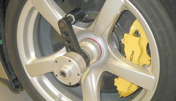
The 2005 and later Porsche Carrera GT wheels/hubs feature a pin-drive center nut with a splined drive design. Due to the high OE torque value specification, this requires a special dedicated Porsche tool for service. This socket tool is part
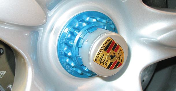
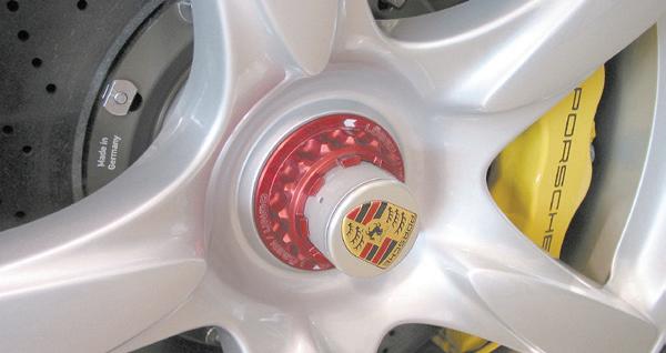
of a torque-multiplier Porsche tool kit. The socket engages the nut, while a special torque multiplier gearbox attaches to the socket. The Porsche torque specification for these nuts is 407 ft-lbs. Since achieving this value with a torque wrench would be challenging to say the least, the torque multiplier tool is required. Simply adjust your torque wrench to 128 ft-lbs and attach it to the multiplier tool. As you pull the torque wrench to a mere 128 ft-lbs, the multiplier gearbox converts this amount of force into an effective 407 ft-lbs.
A customer’s 2020 Chevy Silverado equipped with a 6.6L diesel engine may incorrectly show a message “DEF Low” in the instrument cluster when a diesel engine fluid controller fault is detected (DTC P20FF), instead of displaying the proper “Service DEF System” message. The owner may complain about exces-
sive fan noise at low vehicle speed, and under certain conditions, the diagnostic system may set one or more of the following DTCs: P20EE, P226D, P16F3, and/or P129F. In this case, GM says that no parts are required for this repair. Simply reprogram the ECM and select “Programming,” then “VCI.”
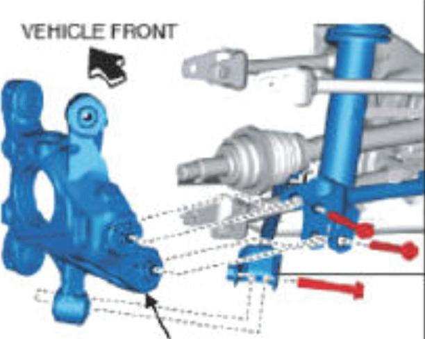
You may encounter a 2016-2021 Mazda MX-5 Miata that has a clunk noise at the rear suspension when driving at low speeds and/or while turning. This may be due to a rattling of the bushing of the upper lateral link in the rear hub support. This may be caused by dimensional variation of the bushing boots in the rear hub support, which can cause poor sealing and allow water to enter the rear hub support, resulting in rust on the pillow ball. The rust then accelerates the pillow ball wear, causing a gap between the body and bearing. The fix: the boots for the rear hub support have been modified to improve sealing. If rustcaused wear is found, replace the hub support (which includes the upgraded seal) using P/N N243-26-11XA (right) and/or N243-26-12XA (left). Always install a new hub nut P/N D651-33042A.
If you need to remove/install a camshaft from a GM LS engine, here’s a tip. There’s no need to remove the cylinder heads or the lifters. Remove all rocker arms and pushrods. With the front of the engine exposed (harmonic balancer, water pump, timing cover, timing chain removed), slowly rotate the camshaft a full 360 degrees. This will push the roller lifters up and into their plastic lifter “buckets/trays.” This will move the lifters away from the camshaft lobes.
Before removing the camshaft, in order to ensure that none of the lifters can accidentally drop down, carefully insert a 22” long or longer 1/4”-diameter metal rod into each of the lifter galley oil galleys. (Insert the rods from the front of the block, in the upper passages
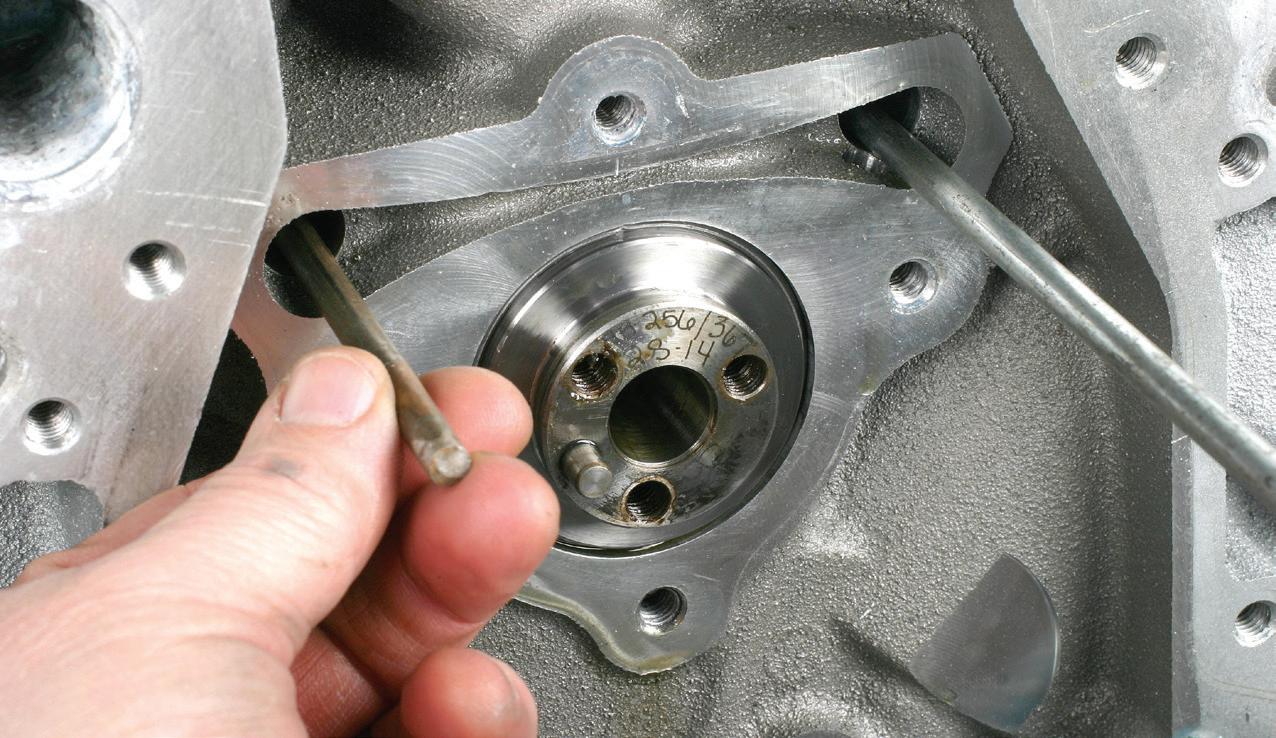
to the right and left of the cam until the rods seat against the rear of the block.) With these rods in place, this will block the lifters from dropping. The cam can then be removed and reinstalled (or
a new cam installed). Once the cam is installed, remove the two rods. Install the pushrods, pushing the lifters out of their held positions back onto the cam lobes.


“There’s no place like home.” That rings true for automotive technicians, too.
BY BRANDON STECKLER // Technical Editor
FORTY YEARS IS A VERY LONG TIME to consider for a career of broken skin, busted knuckles, sweat-soaked clothing and the mental tax you pay each day. And that’s just for technicians who love where they are. But what if you’re not happy? What criteria must be satisfied to call the next shop “home?” Well, I will tell you mine.
Fresh out of GM ASEP school (General Motors’ Automotive Service Educational Program) with a straight-A track record, I was full of vigor and anticipation of a great career ahead as a certified, up-andcoming GM technician. I transitioned to an opportunity with our Saturn franchise and quickly moved through the training curriculum as a fully certified Saturn technician.
The paychecks were astounding! I was one of only five technicians in the store and there was more than plenty of work to go around. Needless to say, it was great to be a flat-rate paid technician in a shop environment like that one.
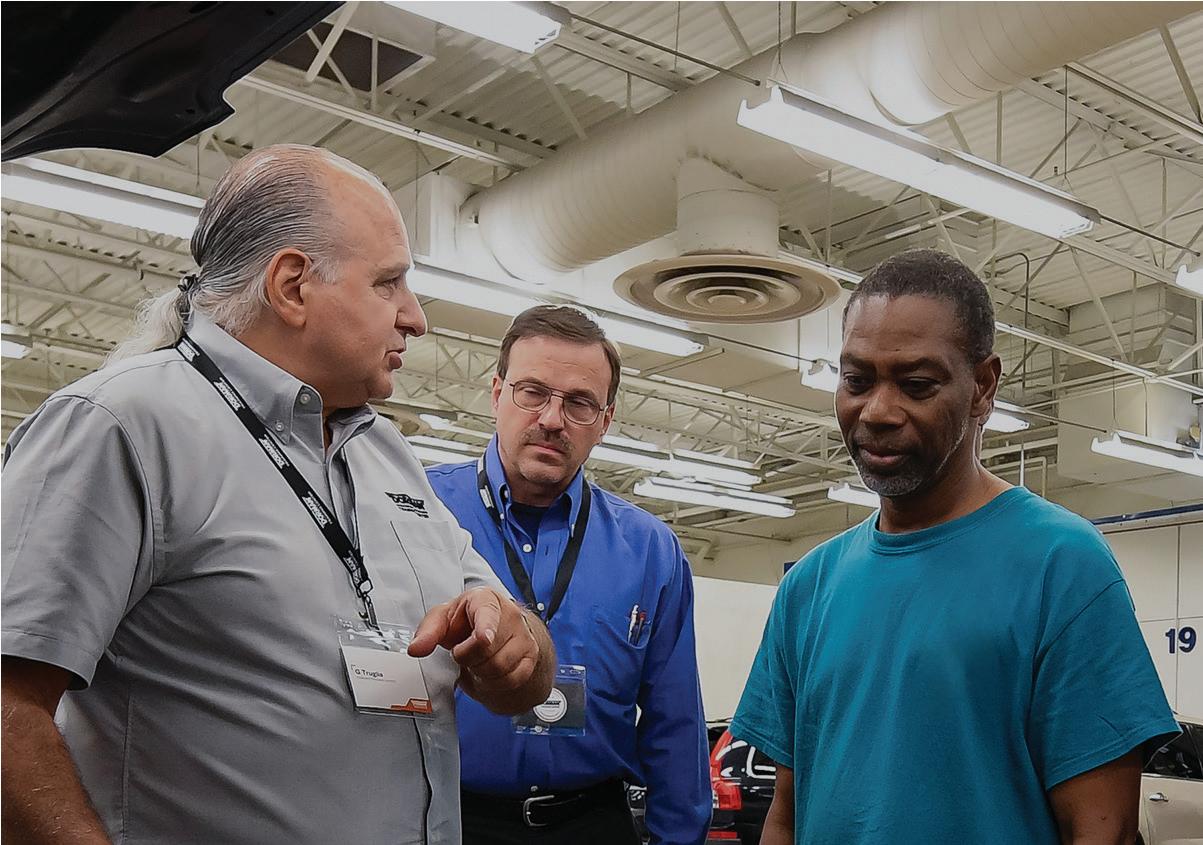
But as time went by, I realized a few things that didn’t sit well with me. It was plain to see that the ethos at the front of the house seemed to have transitioned from, “Let’s be profitable by ensuring our customers are well looked-after” to something more like, “Let’s get whatever we can from them, even if it means they never come back” (Figure 1).
Whether I was correct about that notion or not, I chose to move on. All I can say is not only has that store closed, but that once thriving organization is now extinct. I realized that I wanted to be profitable by helping others. I wanted to be one of the heroes that customers relied on and trusted.
I found myself in the southwest of Florida, fulfilling a tremendous opportunity at my dream job. My primary responsibility in this well-equipped facility was driveability and diagnostics. It seemed
the days of hanging exhausts and slinging brakes were coming to an end. This allowed me to focus my energy on doing what I love — and I got paid to do it. When I shook hands with the shop owner, he and I were in full agreement that I was to be provided regular, paid-for training of my choosing (Figure 2).
Well, the time came for my first training opportunity and as promised, the shop owner sent me to the two-day training course. I had a great time but upon my return (and the next pay cycle) my paycheck was docked 16 hours labor and none of my travel expenses were satisfied.
Upon speaking with the shop owner, he recanted. In fairness, he said, “I never said that. Why would I pay you to go to training? It’s to your benefit.” My point of mentioning this is that moving my family nearly 1,300 miles away from home rested on this agreement. Something similar happened with my “paid-vacation.” After a trip back home, I returned to find that I was docked 40 hours pay and I was told I was not eligible for the (promised) paid vacation for at least two years. This may all sound like sour grapes but I will make my point soon (Figure 3).
Ironically, at the same training event I just mentioned, not only was it the beginning of the end with that shop. It also became the start of something new. This is where I met my soon-to-be new employer. So I left the first shop for an opportunity to work at another well-established shop that was well known in the area.
The man was very generous, offering me not only a cash initiation bonus but he also sent a tow truck for my tools, and paid to have my diagnostic equipment software updated. I looked at him with a dropped jaw and he said to me, “What are you so surprised about? How can you be at your best if your equipment isn’t? This is going to benefit the entire shop.”
Let me first say that this was a very generous thing to do and I don’t want any-
one to get the impression that this should be expected. I certainly don’t wish to set the bar higher than it really is. In my experience, this is not the usual situation and I would never expect it again. My time at the shop grew more fulfilling almost daily. The bonds I formed with my co-workers were very strong and we truly worked like a team (Figure 4) We all had our strengths and we played off each other, like well-planned military-type tactics. Of course, my duties were to address diagnostics/driveability but also included overseeing the shop and preventing bottlenecks. Many times, I served as a liaison to customers, especially when it came to addressing NVH issues. This really saved a lot of time. Yes, I was still a flat-rate paid technician, but my hourly pay was substantial enough

that comes through the door might seem to lead to short-term profitability. But it kills customer retention. Instead, try looking out for the customer’s best interest, just like you’d do for family. This also leads to profitability, but it lasts so much longer, and for all the right reasons.
125445290 | DREAMSTIME.COM

2: Verbal agreements are commonplace in our industry, along with the good old-fashioned handshake. Unfortunately, it’s not good enough. Get every promise in writing. This way, it can’t simply be taken from you.
23830104 | DREAMSTIME.COM
to keep me earning a fair wage — but only if I was willing to work hard — and that was never a problem. There was always plenty of work. This meant the front of the house was doing its job well also. This is a very important, and typically overlooked factor in a flat-rate paid atmosphere.
But things took a slight turn in the wrong direction. My primary duty (to prevent bottlenecks) turned into cleaning up unnecessary messes. And these
occurred due to nothing but sheer neglect and laziness.
One of the techs began to take dangerous short cuts and caused quite a bit of damage to many vehicles. Of course, when the cars came back (or, sometimes never even left) I was forced to address them. At the same time I was forced to abandon profitable work to complete these clean-up jobs. Many times, I had to sacrifice an eight-hour job to do so. The worst of it is to come.

When you are capable
being
of. Don’t let situations like this dictate how you are treated. If you are a valuable
you should be treated with fairness and respect. If this is not something you can acquire, do not be afraid to move on. 169843152 DREAMSTIME.COM

4: Focusing on the team instead of myself led to a larger paycheck in the long run. Besides, being a valuable and contributing team member strengthens bonds in the shop and leads to others respecting you and following in your footsteps. 26015119 | DREAMSTIME.COM

While I was tasked as the clean-up guy, I wasn’t paid extra to do the work.
In fact, I was told that it was part of my job. But here’s my perspective on why that cut deep and didn’t work:
• The offending tech was paid the full amount for a deliberately botched or rushed job.
• He was given my eight-hour jobs to do while I tended to his messes.
• He was never docked pay or reprimanded in any way.
In a polite and quiet manner — and at an appropriate time, after hours when I had the shop owner’s full attention — I shared my concerns with him.
• The current situation promotes this improper behavior.
• It rewards the offending technician.
• It punishes me in several ways (lost opportunity to earn, working for free).
• Customers are noticing and voicing concern of work quality.
• I’m losing my desire to work under these conditions.
Because I don’t think it is fair to offer criticism without a solution (Figure 5), I had a list of ideas, as well:
• Conduct a meeting between the three of us to discuss these occurrences.
• Offer a verbal warning with the explanation of a forthcoming written warning for future occurrences.
• Each neglectful occurrence would require the offending tech to repair the vehicle properly, without additional compensation, or relinquish previous compensation to pay me to make the necessary repair.
• A neglectful occurrence after the written warning would result in termination.
My goal here was not to inflict punishment but offer the shop owner perspective, as well as the offending technician. We all know accidents happen but neglect is simply dangerous and unacceptable. Besides, it’s just not fair to treat faithful team members negatively to compensate for a poor performing technician who
11840690 | DREAMSTIME.COM
shows no sign of wanting to improve. Unfortunately, my ideas fell on deaf ears. There were no hard feelings but I chose to move on to pursue another opportunity (Figure 6).
If at First You Don’t Succeed... Shortly after becoming an instructor, my applied time in the shop got spread thinner with each passing day. The shop where I was working was a great place to work. The shop owner approached me. He recognized my desire to be an instructor and offered me his support. However, he reminded me that I was his shop foreman and he needed my focus if I was going to stay on board. He said he supported whatever decision I made, but he wanted me to go home and think about if I truly wanted to be a technician or an instructor. There was no room for both in this shop. I respected that and chose to be an instructor.
This worked out well for me. A dear friend of mine — who also owned a shop — needed a part-time diagnostician. So I took him up on an offer and kept fixing cars while teaching in the evenings. It worked out well, initially.
Every business exists to make money. But, in my opinion, using the cheapest parts to increase profit margins doesn’t typically work well. And I found that out on almost a daily basis.
A vehicle came into the shop with extremely positive fuel trims under all operating conditions. In almost no time at all, I diagnosed the fault due to a severely under reporting MAF sensor.
The short version of this long story is that this vehicle took 10 minutes to draw a diagnosis and should have taken less than one hour to have it back on the road again. Well, we had it for an additional eight hours. We went through at least five different “white box” MAF sensors and after each consecutive replacement sensor, my friend’s confidence in my abilities grew less.
I finally put my foot down and told him

FIG. 6: If it’s true that Thomas Edison failed to create the light bulb more than 10,000 times before finding success, it’s plain to see that complacency will not lead us to a shop we desire to be at every day. Know your worth and never let anyone tell you don’t deserve happiness, even at work. 70990547 | DREAMSTIME.COM
to get me an OE sensor from a junk yard. (He didn’t want to pay the nearly $400 for a new one.) It fixed the fault. Instead of receiving an apology, he said the real fault was likely an issue in the harness and I fixed it unintentionally with all my botched attempts.
This wasn’t a one-time occurrence. I had the dash out of a Dodge Ram three separate times because of cheap replacement HVAC door actuators. Again, I warned him of the potential for premature failure but he wanted to save a few dollars. I recall that old saying, “you can lead a horse to water but you can’t make it drink.”
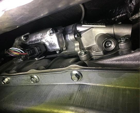
A vehicle came into the shop with a noisy, chain-driven DOHC engine. The noise occurred at cold start-up and disappeared after only two or three seconds. I diagnosed it as faulty VVT phasers and suggested replacement, along with timing components. All was documented clearly on the repair order (Figure 7)
However, several hours later, my parts arrived and the phasers were not
included — just the timing chain components. The shop owner had taken it upon himself to tell the customer that we simply suggest the replacement of the phasers. (This was because the customer didn’t want to approve such an expensive repair.) Reluctantly, I assembled the engine without the replacement phasers and the noise was still there. Of course, this was considered another misdiagnosis on my part.
However, as luck would have it, a mutual friend of mine and the owner’s showed up at the shop to say “hello.” He inquired about the owner’s bad mood and when it was explained he chuckled and confirmed with the shop owner that the mistake was not made in the shop, but over the phone. Although it made me feel better to hear that third-party opinion, it didn’t change a thing. But what took the cake is yet to come.
There was an accident in the shop where two vehicles gently bumped each other. (It happens.) There was minor paint
damage but it did require some body work to repair. The shop owner’s father owned a body shop down the street. Without notice, my friend (the shop owner) garnished my paycheck of nearly $800 for the incident. This was a huge loss to me because I had no time to prepare. Not only was this unethical, but it was illegal as well. I didn’t press the issue but he fired me not too long after that. However, I tell you all of that not to complain or gain your sympathy. In the end, when he decided to fire me, he sat me down in this office and opened a “book of shame,” as he called it. It was a diary describing every negative situation that occurred and “how much money I cost him on a daily basis.” Included was every single situation that occurred due to faulty parts. Not once did he acknowledge the bad parts. Instead they were all due to misdiagnosis, according to him. And that was the basis for my termination.
We were friends for a long time but not after this experience. In fact, we haven’t spoken since. It is a shame but there are lessons to be learned from this as well as every other situation included above.
You could look at all of those perceived negative situations and consider them as opportunities to complain. However, that is not my goal. Like all of you, I’ve grown as an individual and I know what I consider exemplary performance for a technician. I also know what I desire, and what I’m not willing to tolerate. Here is what I’ve learned for myself and my standards:
• Treat my customers like family — with honesty and integrity, and always be accountable.
• Be a valuable and contributing team member who pulls your own weight and gives more than is required when others can’t. Set an example so others respect you and want to follow you because you’re a leader who leads and doesn’t just delegate. My thought is “take care of my team and my team will take care of me.”
• Don’t settle for neglect and disrespect simply because you have been told it is in your job description. It’s understood that the customer is of the utmost concern. I feel the team members are too, and when we do right by our people, everything else will fall into place. The team members are happy to take care of the customers. However, when you are not being treated fairly, be polite, choose the appropriate time, and speak about your concerns. Do so in a fashion that offers solutions instead of just complaints.
• When interviewing for an opportunity, have your standards written down. Share them with your prospective employer and get any offers in writing. Be sure to hold your employer accountable for the promises made and don’t ever take a job that doesn’t support your growth and prosperity as a technician. Your time will be better invested elsewhere. Don’t ever let anyone hold you down.
• Do your job properly and thoroughly. Be sure to document properly and explain your documentation if need be. Just because it’s written doesn’t mean it’s interpreted as intended. When communication is good, mistakes and mishaps are reduced. Share your concern for installing sub-par components and be sure to document that as well. No longer will I let an employer tell me I’m at fault (and working for free) when the fault is not of my actions.
• As a blanket statement, I’m no longer a believer in the flat-rate system as it stands. However, it can work well under the right situations. If I’m ever offered a flat rate position, I would make it known that my prosperity depends on the efforts of others. I wouldn’t accept flat-rate employment unless the conditions to do so successfully were in place. And that includes the abilities and communication skills of the counter staff and service advisors. That also means I monitor a day in the life of that counter staff. And, yes, I have visited shops to

FIG. 7: Document everything thoroughly. I did so in a fashion that I felt would hold up in a court of law. True, this can be time-consuming but you get used to it. Not only will you find yourself doing a more thorough job, you tend to get paid a bit more in tickets where applied time (straight-time) was referenced for pay. Every task became a labor operation and I was compensated for almost everything I did.
3251673 | DREAMSTIME.COM

FIG. 8 :Establishing standards derived from your past experiences will let you know what you desire in a place of employment, what you are willing to tolerate, and simply what tells you to pass on an opportunity. Too many years of me letting things go led to a bunch of wasted time and working in nearly 20 shops across four U.S. states. Creating a list of my personal standards will prevent me from ever doing that again.
36740275 | DREAMSTIME
interview them for their performance. They must suit my standards if I’m going to call that place “home.”
Right or wrong, they are my personal feelings. I’m not sharing them with you to convince you of anything. But I care about each and every one of you like brothers and sisters and love you all dearly. I want you to think long and hard about what you want as a technician, as an employee, as a team member, as parents/spouses, and as the person you wish to be — the person who makes you proud to look in the mirror. If I can help you recognize and become that, this article served its purpose to help you find “home” (Figure 8)


BY ERIK SCREEDEN
NOBODY LIKES TO BUY TIRES. To add insult to injury for the vehicle owner, all too often tires are being replaced not because they have come to the end of their service life, but rather something has gone amiss, and they have prematurely
worn to the point they are no longer safe or comfortable to drive on. That is where there is an opportunity for the technician and shop owner to come in, remedy the underlying issue, become the hero for the customer and realize revenue.
It’s all too often a vehicle comes into a shop with abnormal tire wear and an opportunity is missed. A customer discovers abnormal wear, only seeing the worn tread but not knowing what they are looking at. They think it must be time for a new set of tires, and they look at some pricing online and then make an appointment. The tires are replaced by a general service or tire technician.
Once changed, the customer is sent on their way not knowing that they are probably destined to repeat the process in the not-too-distant future.
They are sent on their way without anyone at the shop outside of a general service technician getting their hands

on the car and seeing those tires up close. When that happens, all of that opportunity drives away.
Tire wear, especially abnormal wear, does not occur in a vacuum. Experienced technicians, service advisors, and other industry personnel typically can look at a worn set of tires and quickly come up with a hypothesis on what caused that wear. But that ability comes with experience, and often it’s the least experienced in our industry who perform most tire services. The natural progression of a technician’s career has him or her starting out performing these basic services. Fluid and filter services, tire and TPMS
service are a great way to build new technicians’ skills and confidence at the beginning of a career. But a big part of progression and growth is educating new technicians on what to look for, especially when it comes to critical componentry like tires. It keeps that growth arc moving, keeps customers safe and satisfied, and maximizes sales opportunities for the business.
Even to the untrained eye, things like camber wear, cupping, and feathering can easily be detected. Experience is being able to take that visual cue and associate it with what the cause might be. This is where the growth comes in for the newer members of the team. So, let’s review some of these common wear patterns, and some of the opportunities they present for the shop. I am going to start off with one of the most common wear patterns, and that is feathering.
Feathering is exactly what the name implies and it is caused by excessive positive or negative toe. Feathering can be detected across the tire and presents itself as a feathered edge on the inside or outside of a tread block. This wear occurs because of the scuffing action the tire experiences as the tire scrapes across the pavement. The more excessive total toe deviates to the positive or the negative, the more exaggerated the feathering will be. Because feathering occurs due to toe changes, and toe is affected in varying degrees by changes in camber and caster, the primary cause of the incorrect toe angle can vary greatly. Anything from bent components, loose inner and outer tie-rod ends, to worn out springs that have degraded ride height can end up being the root cause of the condition. But the presence of feathering is a key indicator that something affecting the alignment of that vehicle needs to be addressed.
Camber wear is another prominent tire wear condition that shops see daily.
Camber wear is found on the tread block nearest the shoulder of the tire. It can appear on the outer edge of the tire, for instances of positive camber. Or more commonly on modern suspension designs, the inside of the tire, indicating excessive negative camber. Just like the feathering mentioned above, it can be caused by a myriad of reasons, but loose wheel bearings, ball joints, and again degraded ride height are amongst the highest offenders. Now it should be mentioned that abnormal wear on both the inner and outer edge of the tire should be taken as an indication of underinflation. TPMS has been around for so long now that many technicians take for granted that tire pressure is something that is addressed immediately by the vehicle owner, but never underestimate a person’s ability to drive extended periods of time while ignoring all sorts of malfunction indicator warnings on the dashboard and all the bells, chimes, and pop-up messages that can go with them. Tire cupping or scalloping is another tire wear pattern that is commonly seen and in this instance, heard by technicians and vehicle owners. Tire cupping is observed as dips, or “cups” around the tire tread surface. This effect, depending on severity, can be very noticeable by the customer, often accompanied by a noise complaint. And just like camber and toe wear, can have its root cause be several offenders, but taking a hard look at ride control components is a great place to start. The primary function of a shock or strut is to control spring oscillation and keep the tire firmly in contact with the road surface. As the oil found in the shock or strut degrades or leaks out, its ability to work properly is compromised. Not only will ride quality and handling/braking ability of the vehicle be reduced, but the tire that at one time was consistently loaded and planted on the pavement now has the ability to move around — for lack of a better term. This can cause the tire to scallop and wear unevenly.
Feathering, edge wear, and cupping are far from the only tire wear issues a technician will come across, there is center wear from prolonged overinflation (or the spirited use of the throttle in the quest to transform rubber into smoke), cracked tires from age and dry-rot. Plus some tires come to the end of their useful life due to nothing more than normal use. But the former are the wear items most closely associated with worn parts and alignment issues. We have identified the issues, now what actions should be taken with that information? That is where the communication portion becomes important.
As we talked about in the beginning, if there is a breakdown of communication within the shop, opportunities for additional revenue will be missed, and just as importantly we are sending customers out the door with an expensive new set of tires that are not going to last as long as they should because of an underlying vehicle issue. It’s not unheard of in even medium-sized operations for the person who is installing a set of tires to be different than the person performing a majority of the alignments. And both of those people can be different from the person who does a lot of the undercar work. Building a culture of communication and mentorship will pay off. Think of it like TSA: If you see something, say something. That “green” general service technician should feel empowered and given the time to perform a thorough inspection of the customer’s vehicle.
Just like everything in the automotive industry, inspection technology has evolved. The traditional inspection sheet filled with green, yellow, and red boxes that offer very little insight for the customer are often woefully out of date with modern vehicle technology. Because of this, the sheets are often
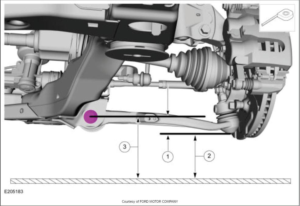
MAKE SURE to consult repair information to not only determine the proper measurement, but also the proper measurement procedure. In the instance of the fifth generation Ford Explorer, there are actually two measurements (3 and 2) taken and then ride height equals 3–2. FORD MOTOR CO.
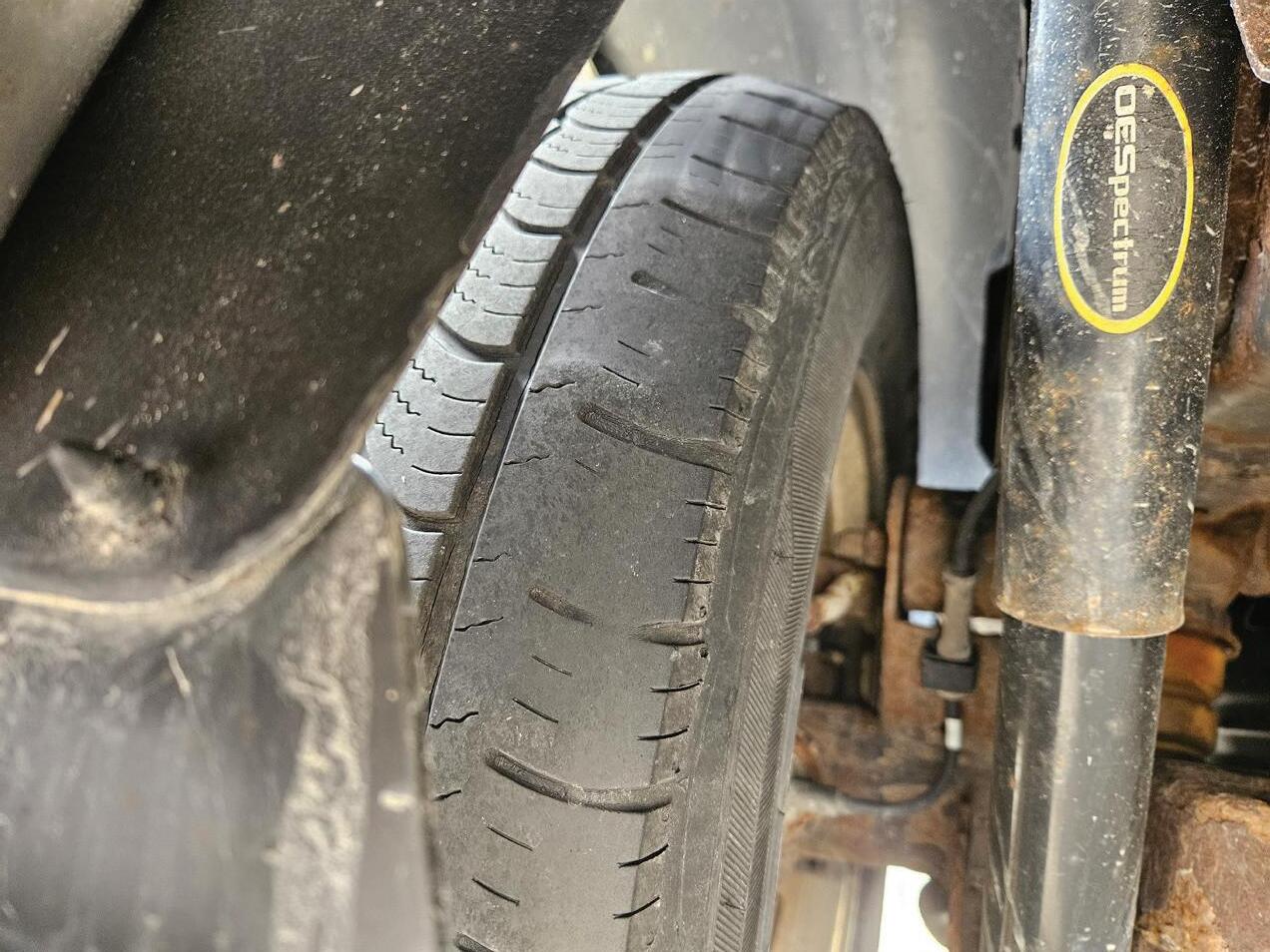
PHOTO BY AUTHOR
simply pencil-whipped by the technician. These forms have fallen out of favor for modern digital vehicle inspection (DVI) technology. DVI platforms allow technicians of all levels to digitally document the condition of vehicle systems and
attach photo and video documentation to support their findings. These reports are easily attached to work orders, estimates, and shared with every stakeholder in that vehicle’s repair journey. Many of the popular shop management systems


work seamlessly with DVI platforms on the market today. If your shop is not currently using a DVI solution, I highly encourage you to do some more research on the subject and look at some of the options on the market.
I have long felt that tires are the easiest way to sell undercar and ride control components. It’s much easier for a vehicle owner to make the connection between tire wear and worn parts when the vehicle is in for that tire service. Armed with the tire evaluation and their findings from a thorough inspection of the rest of the vehicle, the technician has most of what they need in order to communicate effectively with the front of house staff to get an accurate estimate on what the vehicle needs. The last piece of that puzzle is the recommendation of corrective measures to get that vehicle back in proper alignment to keep that customer on the road longer with the new set of tires.
Tire wear issues rarely occur in isolation. For example, if both front tires show accelerated camber wear on the inside edges along with feathering, it suggests a combination of excessive negative camber and toe. Feathering alone might point to a toe problem, but when paired with camber wear, the root cause likely involves components affecting both angles. Worn ball joints, hub assemblies, and control arm bushings are common culprits, but if an inspection has ruled those out and the wear is uniform, the technician should consider one often overlooked factor, ride height.
Vehicle ride height, depending on suspension design, can be a key contributing factor to tire wear concerns and is often completely overlooked by technicians. Two of the more common styles, McPherson and short, long arm suspension styles, because of their design, will induce a change in camber angle (and in turn toe as well) as the vehicle’s ride
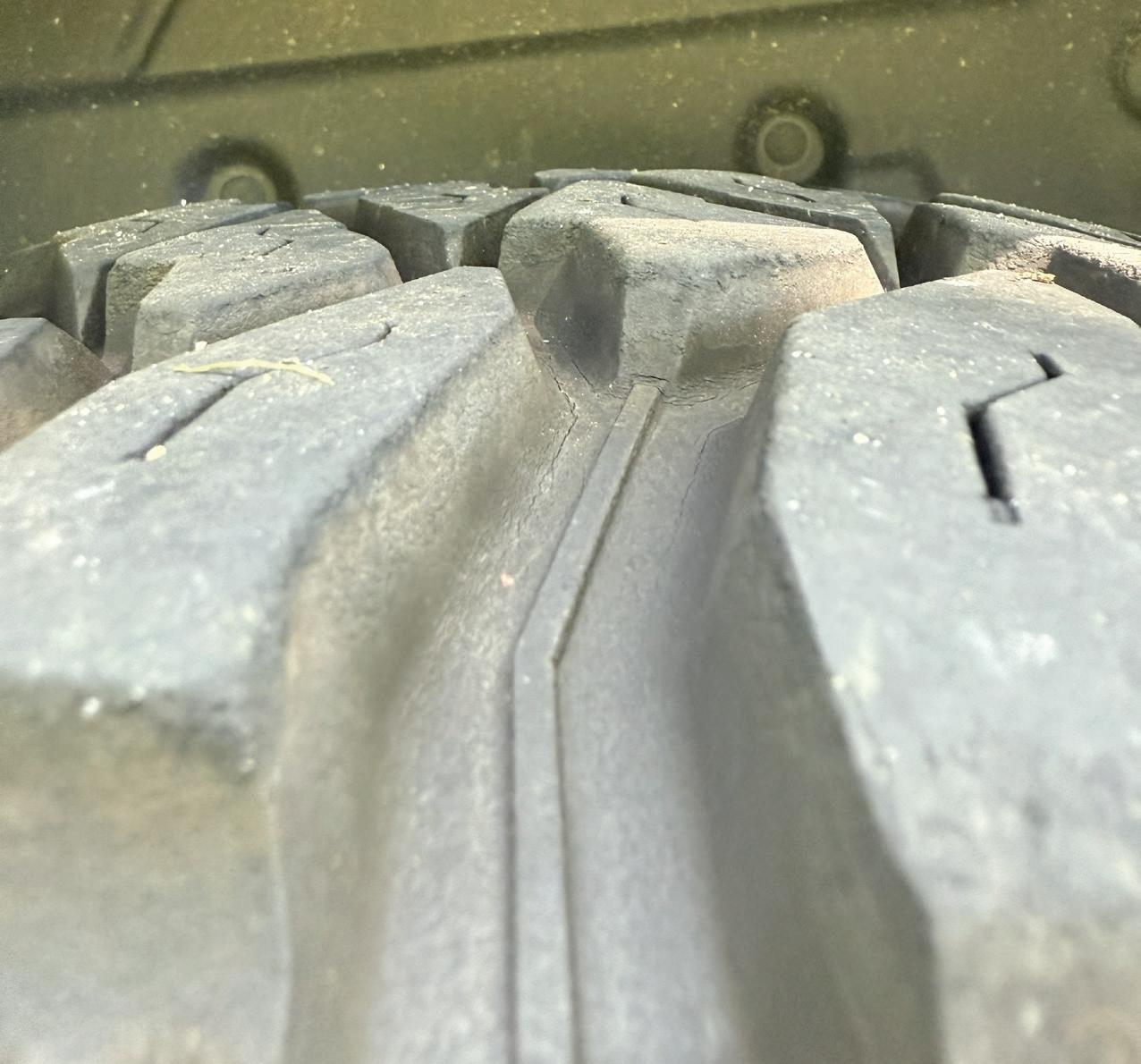

PHOTO BY JUSTIN KIDD


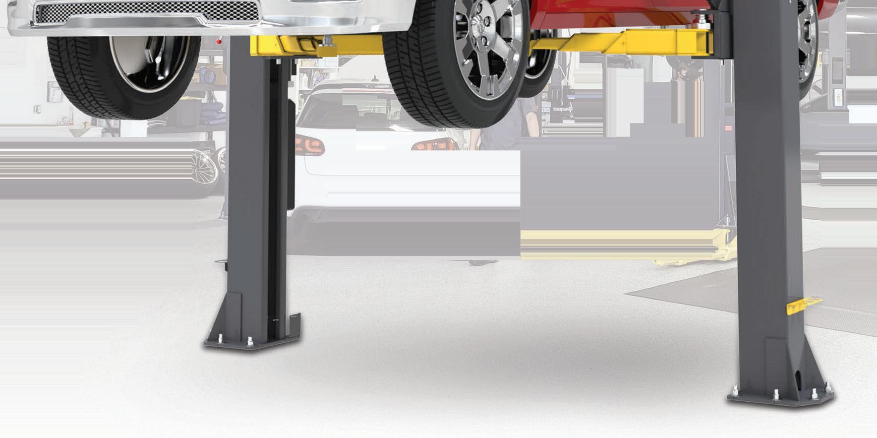


Our 10AP Series offers the convenience of wide or narrow installation wrapped up into one configurable package. This durable, safe, and reliable car lift features an expandable top beam and BI-METRIC™ arms to suit virtually every vehicle lifting requirement – symmetric or asymmetric. The 2-in-1 design gives operators the option of loading vehicles either symmetrically (centerline of vehicle at column) or asymmetrically (centerline of vehicle behind column). The simple, yet highly sophisticated design is sure to keep operating costs low and productivity high. Check out the full line of 10AP lift series at bendpak.com or call us at 1-800-253-2363
height changes. More often than not, this is a condition of ride height due to worn springs, but it can just as easily be because of new ride control restoring factory ride height or even a leveling kit in a pickup. Springs wear and settle; linear or progressive coil, torsion, leaf — there isn’t a spring design immune to this. And if the suspension design dictates there will be a change of alignment angles with this change of ride height, it’s something a technician needs to keep front of mind.
The nice thing about ride height is it’s a great way to demonstrate to a customer the need for ride control products that will restore these critical angles. Simply using the alignment machine, then sliding air over hydraulic jack found on most drive on hoists, and a few photos are an excellent way to drive additional revenue. Often bumping a vehicle up a bit to its original ride height will bring those
camber, caster, and toe angles pretty darn close to where they need to be. It’s a great way to demonstrate to the customer how investing in ride control products will help prolong that expensive new set of tires they had to purchase. Because the degradation in ride height is not going to improve, and even if there is enough adjustment left, the vehicle is only going to fall back out of alignment quickly.
When looking at ride height and tire wear, a technician always needs to be on the lookout for clues of tire wear conditions that are not always super obvious. Spending the majority of my adult life in Minnesota, two key realities about the colder months set in very quickly for me. First, the professional football team that resides here will always find new and inventive ways to rip the hearts out of the fan base. Second, dealing with white, fluffy, frozen precipitation is an
ever-present reality for the better part of half the year. Many trucks and SUVs in northern climates drive significant miles with heavy plows mounted on the front of the vehicle. Depending on suspension design, that weight can have a significant impact on tire wear. Since the late 1980s GM used an independent front suspension design, Ford has had their Twin I Beam and later a SLA design in the halfton trucks, so ride height changes are a concern. Ford Super Duty and Ram have held firm with a solid axle design, so ride height is not as much of a factor. But if you notice abnormal tire wear and a plow mount on an independent front suspension vehicle, it is worth the conversation with the customer to inquire about the amount of time that vehicle is driven with a plow on it. If it’s significant, it may be worth the effort to align the vehicle with the plow on it. If it’s an older model truck


that is still using torsion springs, even making a ride height adjustment with the plow hanging can significantly improve tire life on those vehicles.
Use
Tire wear should never be treated as an isolated issue but rather a conversation starter, a diagnostic clue, and a business opportunity. By encouraging communication between technicians, advisors, and customers, and by empowering even entry-level techs with knowledge and confidence, shops can avoid missed opportunities, keep customers safe, and boost revenue. The goal is simple: Don’t just replace the tire but solve the problem that ruined it. That level of thoroughness builds trust, improves retention, and ultimately transforms routine tire service into a critical part of your shop’s success story.


BY MIKE MAVRIGIAN
WE COVER THE BASICS of piston ring fit, assembly techniques and rod bolt tightening, including when to turn to the specifications from piston ring manufacturers.
Piston Ring Fit
While OE direct replacement piston rings likely will provide the correct end
gap (based on original cylinder bore diameter or if the bores have been reconditioned and oversized in whatever oversize listed by the engine maker), always check to verify ring end gap. In some builds, the rings must be file-fit to obtain the recommended ring end gap. File-to-fit rings are slightly oversized, allowing the builder
to obtain ideal ring gaps for the top and second rings. Refer to the piston maker’s specs for preferred gaps.
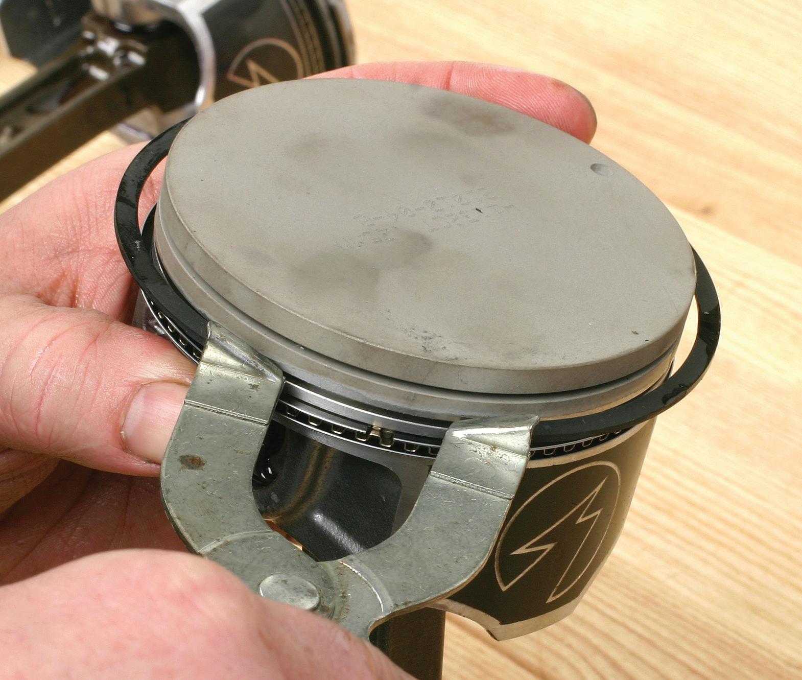
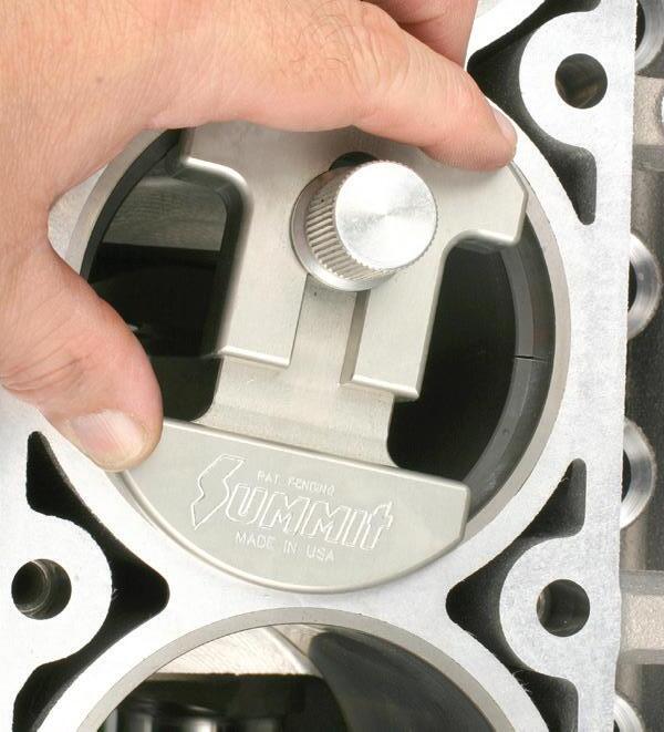
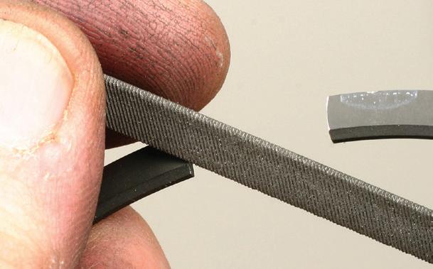
First, make sure that the cylinder is clean and dry. Carefully compress a ring by hand and insert the ring into the cylinder. (Make sure that the ring is oriented properly. A dot or other mark will
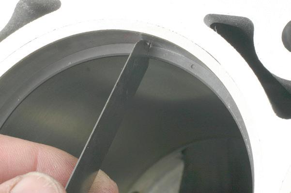
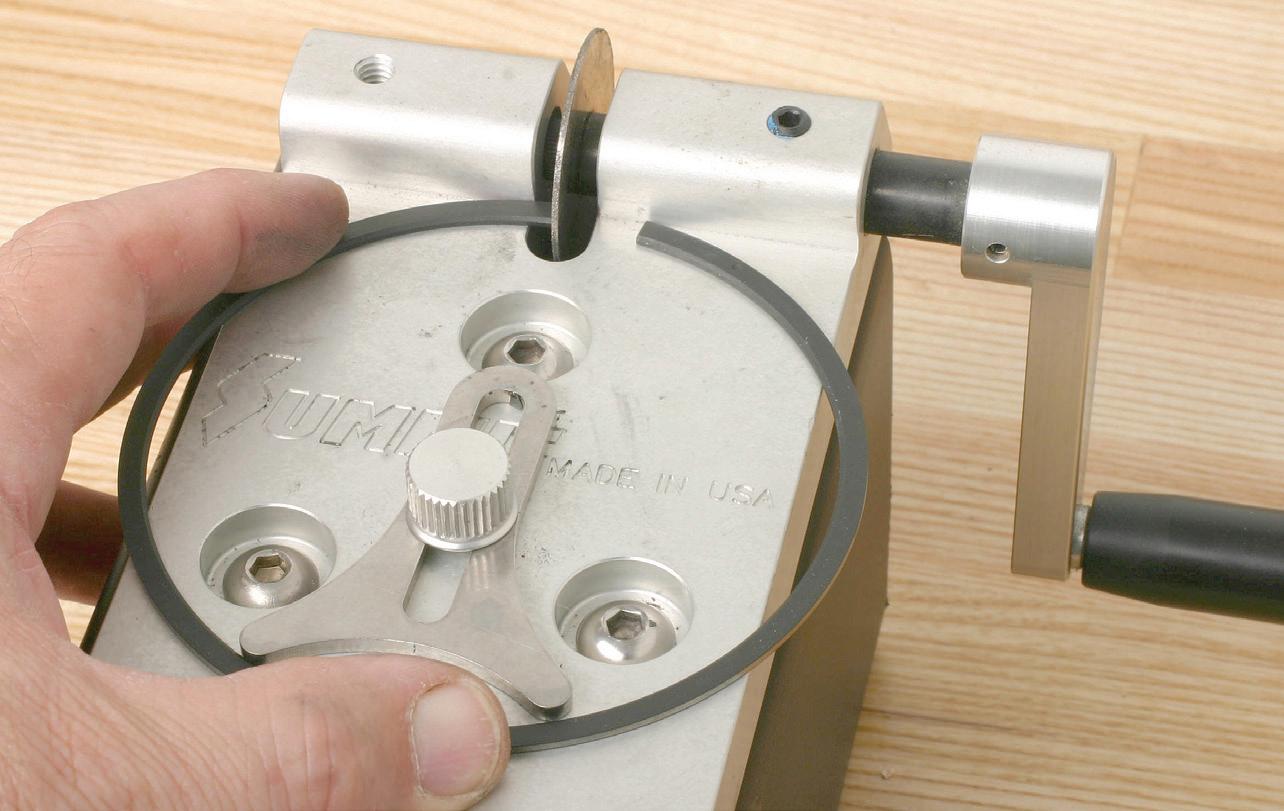
indicate the top side.) Push the ring into the bore by about 1/2” to 1” below deck. It is imperative that the ring is evenly located/ squared, with the distance from the top of the ring to the block deck equal along the entire circumference of the ring. This can be done by checking installed depth with a caliper, or with the use of a dedicated ring placement tool that pushes the ring squarely into the bore. Check the existing ring end gap with a feeler gauge. Remove the ring and file the ends, and re-install to check the modified gap. A ring filing tool equipped with a diamond wheel makes the task easier and more accurate. Various types of ring filing tools are available. If using a hand-operated crank tool, hold the ring flat on the tool base and rotate the abrasive wheel against one end, then flip the ring over and file the opposite end, using the same number of strokes at each end. Perform this task in small steps and re-check the gap in the bore. If you file too much, the gap will be too great and the ring must be replaced. More sophisticated ring filing tools feature electric motors and can be preset to achieve a desired gap. Regardless, after filing, each filed end must be carefully deburred using a small hand file or a built-in deburring wheel (depending on the specific tool).
Some builders tend to check ring end gaps using one cylinder, while others dedicate each pair of rings to individual cylinders. The latter is more precise, as cylinder bore diameters might differ by a small amount. As each pair of rings is final-gapped, keep them together and label with regard to a specific cylinder. An easy method is to create a layout sheet of paper on a workbench, marking each location for cylinder number.
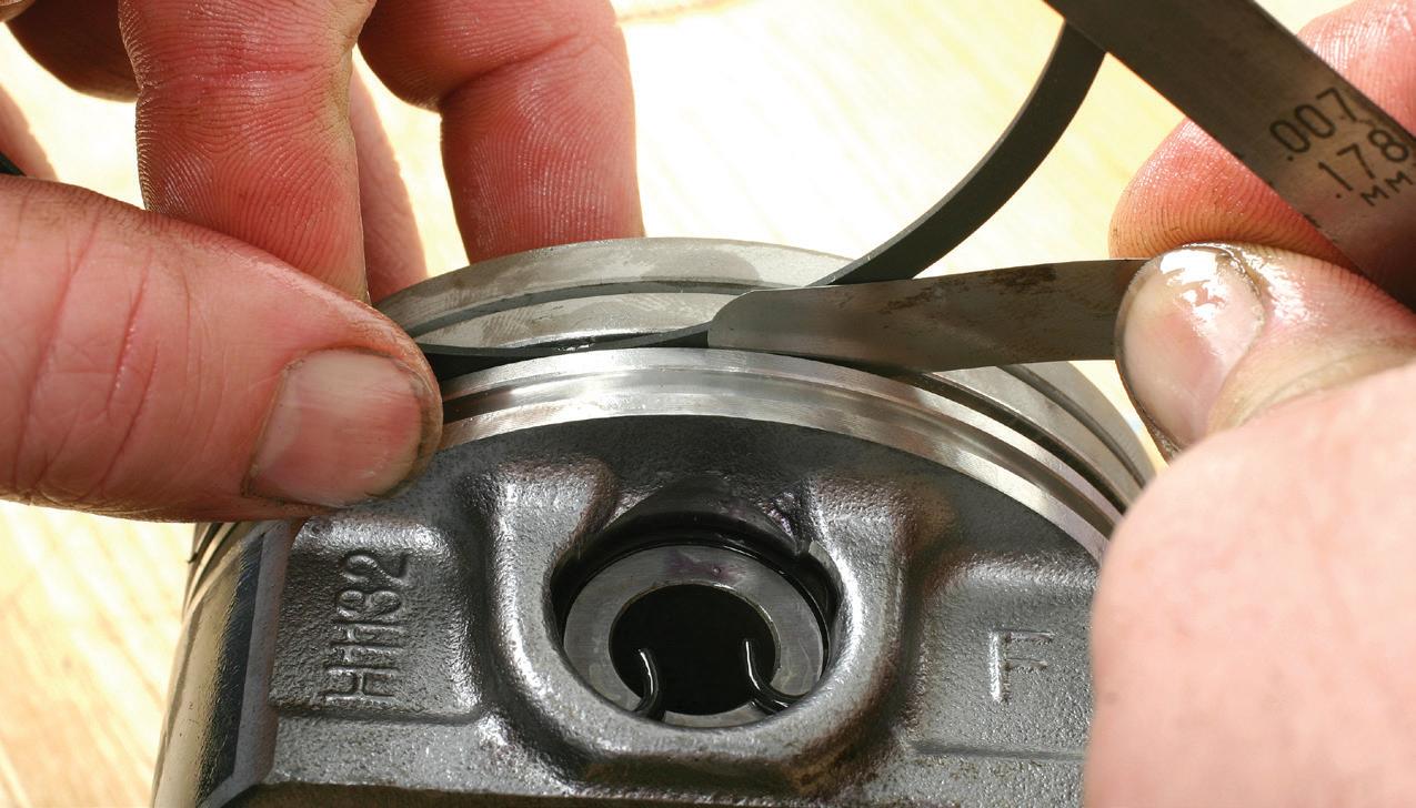
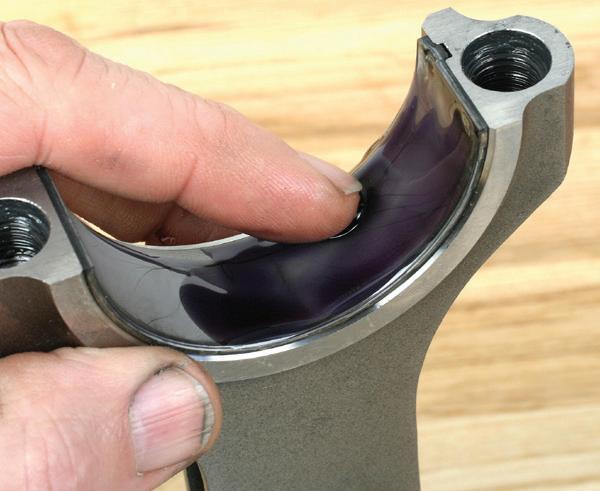
Check and verify ring fitment in the piston ring grooves referring to OE specs or the piston maker specs. Verify back
clearance. This is the depth that the ring seats in the ring groove. With the ring fully seated to the depth of the groove wall, the ring should not protrude beyond the land. Check side clearance using a feeler gauge. With a ring seated on the groove land, measure clearance between the top of the ring to the upper shelf of the groove. This is typically in the range of 0.001-0.003”.
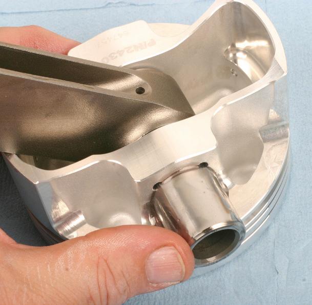
OE engines typically feature a press-pin fit of the piston wrist pin to the connecting rod. The pin is free to rotate within the piston pin bore, while the pin is interference-fit to the small end of the connecting rod. Disassembly or assembly of the connecting rod to the piston is done by heating the connecting rod small ends in a dedicated rod heater, which slightly expands the inside diameter of the rod small end. The piston is then positioned onto the rod small end and the pin is inserted. As the rod small end bore cools and contracts, the wrist pin is secured in the rod small end.
Rather than using a wrist pin that is press-fit to the small end bore of the rod,

some engines use a “free floating” pin, where the pin is free to rotate in both the connecting rod small end and the piston. In these applications, the rod small end pin bore features a bronze bushing to protect the pin and promote lubrication. A notable benefit to free-floating pins is that it enhances ease of disassembly/assembly, as opposed to pins that interference-fit to the rod small end, since no press or heat is required.
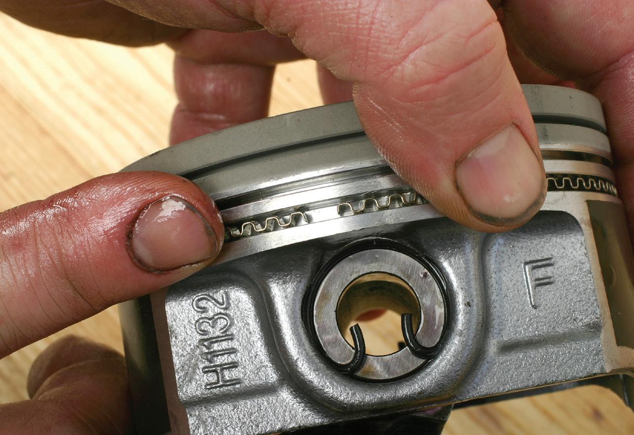
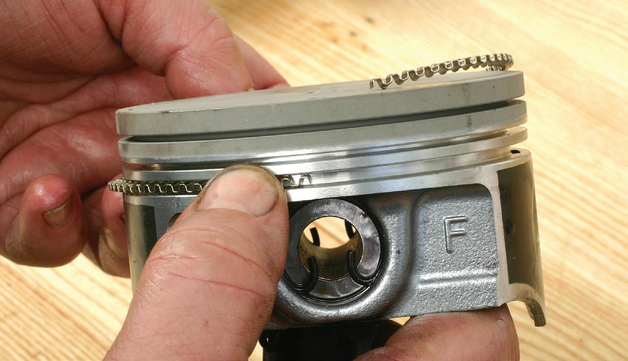
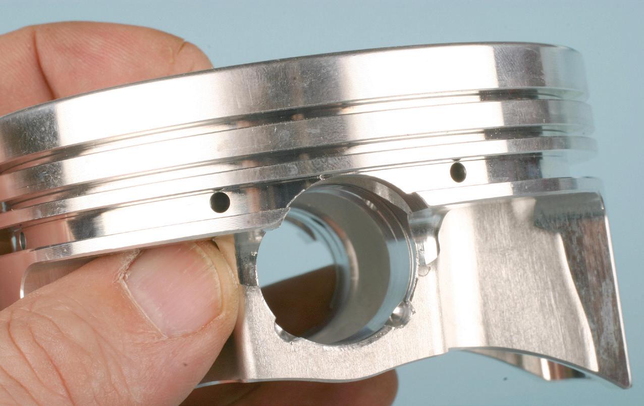
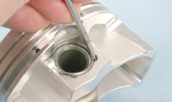
In a full-floating pin design, since the pin is free to slide within the rod and piston bores, a method of retaining the pin in place is critical to prevent the pin from sliding out and hitting the cylinder walls. Pistons that accommodate a free floating pin will commonly feature a groove at each end of the pin bore to accept a pin lock.
For more common pistons that require pin retention clips, depending on the pis-
ton maker’s design, this will require either a flat circlip at each end of the pin, a single round-wire circlip at each end, a single flat-wound spiral lock (often referred to as Spiro-Lock) at each end, or in some cases, two spiral locks at each end.
Installing a circlip that features eyelets is done with a pair of circlip pliers (compressing the clip, inserting into the groove and releasing tension). Traditional roundwire clips are compressed, slipped into the groove and released. Another style of wire clip features short angled “legs” at each end. (They are offered under the trade name “Kramm-Lox” by some suppliers.) The short “legs” engage into the piston pin bore’s clip service notch, preventing the clips from rotating.

Installing spiral locks can be tricky for the first-time user but as with many procedures, once you become accustomed to the task, it’s not that hard. Slightly pull


Dayco is celebrating 120 years of innovation and 120 years of helping technicians get the job done right.
From OE-quality parts you can rely on to expert support, training and one of the most expansive kit offerings, count on Dayco to move forward, always.
the spiral-wrapped lock apart with your fingers just enough to create a slight “coil” to expose one end. Insert the exposed end into the groove, then using a small flat blade screwdriver, push the lock into the groove by walking pressure along the clip until it fully engages and snaps into the groove. Visually confirm full seating, and tap the opposite side of the wrist pin against the clip to confirm that it’s fully seated. Special spiral clip drivers are available to ease installation, but seasoned installers develop a “knack” and tend to install spiral locks using their fingers. Spiral locks are available for all common pin sizes. Aftermarket performance piston makers include pin locks with their piston kits. (Styles of locks may vary as determined by the piston maker.)
A couple of important reminders:
• When using spiral locks, DO NOT re-use them. Install new spiral locks

during each engine assembly. Also, avoid over-stretching spiral locks.
• Some applications require the use of pistons that feature a short CD (compression distance). Piston CD refers to the distance from the center of the wrist pin bore to the piston dome. Depending on the application, the CD may be reduced to the point where the wrist pin bore intersects the oil ring package groove. In this case, the piston’s oil ring groove is slightly taller, allowing the installation of an oil ring support rail on the ring groove’s land, providing a “complete” floor for the oil ring at the pin bore locations where the bore encroaches into the oil ring groove. Be aware that because the pin bore is raised, resulting in the bore intersecting the oil ring groove, the connecting rod and wrist pin (and pin locks) must be installed prior to installing the rings. If the oil ring package and


support rail is installed prior to pistonto-rod connection, access to the pin bore will be obstructed.
When a set of pistons requires support rails, the rails will be included along with the piston ring set. A support rail features a small male “bump” protrusion on one side of the rail. The support rail must be installed so that this “bump” faces downward, and with the bump placed directly over the pin, within the void area of the oil ring groove. This bump serves as a “stopper,” preventing the support rail from potentially rotating and preventing the rail’s gap from entering the void area.
After installing wrist pin locks, as added verification, use a brass drift and tap each end of the pin to again make sure that the locks are solidly captured in their grooves.
Rings must be installed carefully to avoid ring distortion. The support rail (where applicable) can be installed by hand, as well as the oil ring package (oil expansion ring, followed by lower oil ring scraper rail and upper oil ring scraper rail). Make sure that the expansion ring ends butt together and do not overlap. Once the lower oil ring rail is installed, this will hold the expansion ring together, preventing overlap. The second ring and top ring are then installed using a quality piston ring expander tool. Orient the ring end gaps per the automaker or pistonmaker recommendations. The primary goal is to prevent any of the ring end gaps from aligning to each other. Be aware that during engine operation, the rings will tend to slightly rotate in their grooves, so top and second ring end gaps should be placed well away from each other to eliminate this concern.
As far as ring end gap placement is concerned, one commonly accepted placement is that the gap of the top ring should be about 90 degrees from the gap of the second ring. End gaps of the oil ring scraper rails are commonly installed 180 degrees apart. Another approach is that the top and second ring end gaps are 180

degrees apart, and oil scraper gaps are about 90 degrees apart. If in doubt, follow the pistonmaker’s gap orientation specs.
With regard to top and second ring installation, directional rings feature a dot or the word “TOP.” Install so that the dot or TOP stamp faces upward toward the piston dome. If the top and/or the second rings feature no orientation marks, the ring is non-directional and can be installed with no regard to top/bottom. Note that if a ring is stamped “TOP,” this refers only to ring orientation and does not indicate that the ring is the top compression ring.
Once the piston/rod assembly is complete, install rod bearings to the connecting rod upper saddles and lower caps. Pay close attention to the rod bearings. The back of the bearings will likely be stamped “upper” or “lower.”
Apply oil or assembly lubricant to the exposed bearing surfaces. Make sure that the cylinder bore walls are clean and free of any contaminants. Lightly oil the cylinder walls. Rotate the crankshaft to position No. 1 cylinder rod journal at/near BDC (bottom dead center). This will allow optimum access to the connecting rod bolts.
In order to allow entry of the piston into the bore, the rings must be compressed to a point of allowing the rings to enter the bore. Use a quality piston ring compressor tool to secure the rings. Several types of ring compressors are available in both diameter-adjustable and fixed-size versions. While the “barrel” style (wrapped-layer tempered sheet metal) is a common type, a billet ring compressor provides a much easier and more precise manner of ring compression/piston installation. A billet ring compressor is machined from aluminum stock and features an internal taper (wider at the top and reduced diameter approaching the bottom). The only downside to billet ring compressor tools is cost, as a specific bore diameter version is required for a given cylinder bore diameter. While a barrel style compressor may handle a specific range of bore diameters, a billet
IF THE pin bore does encroach into the oil ring groove, a separate support rail must be installed at the bottom land of the oil ring groove before the oil ring package is installed. This provides a complete footprint for the oil ring. The support rail will feature a small male bump. When the support rail is installed, this bump must face downward and be located at the top of the pin bore where the bore enters the ring groove.
BY AUTHOR
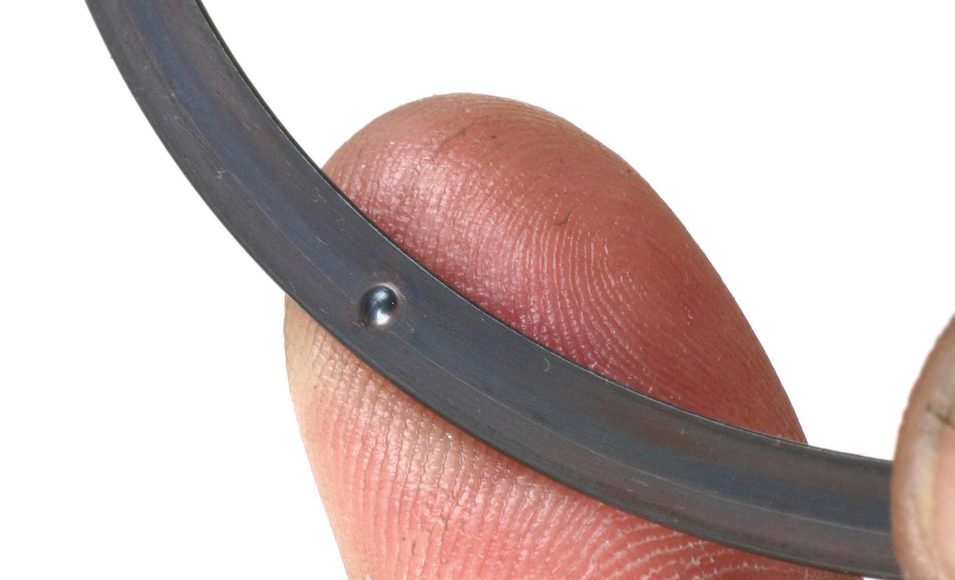
IF THE piston/rod combo features a free-floating wrist pin, a method of preventing the pin from sliding out is needed. Shown here is an example of a wire clip.
BY AUTHOR
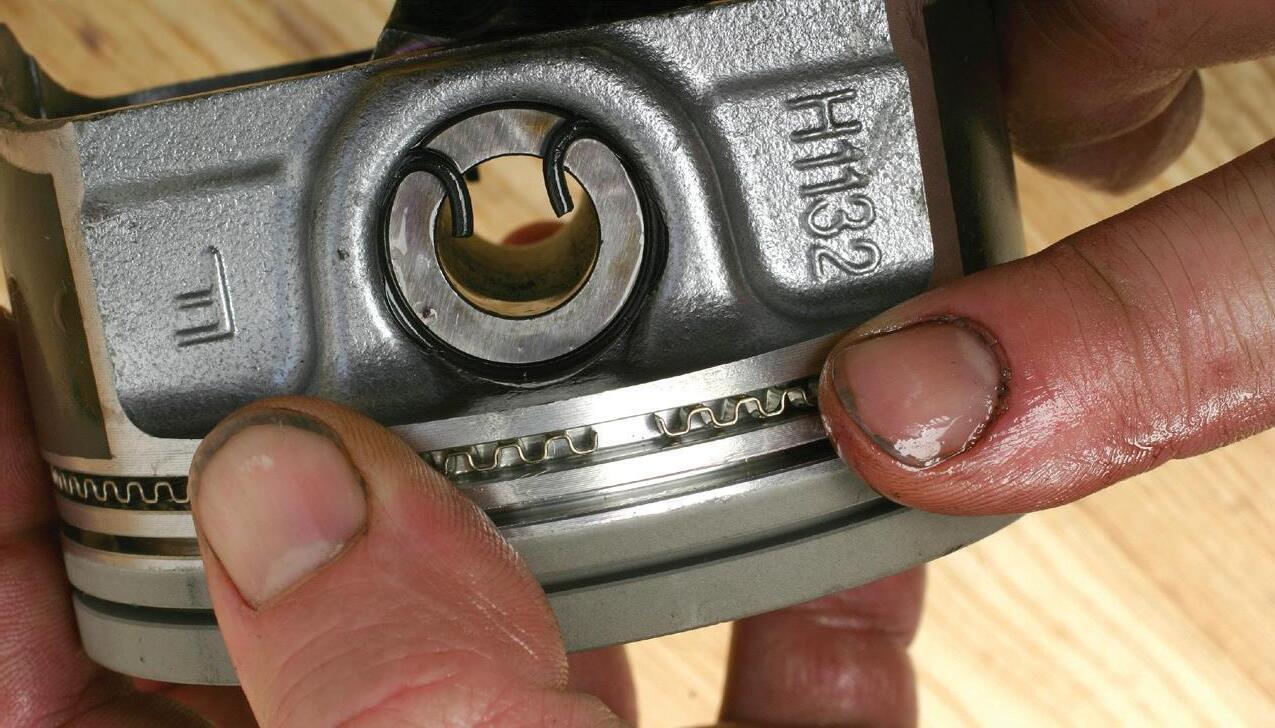
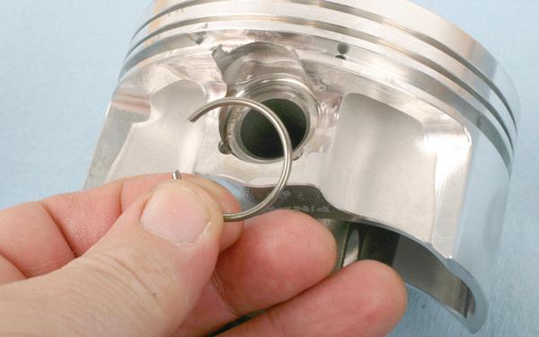
INSTALLING A wire clip. Notches at the pin bore edge provide access for a small tool to guide the clip into place. The clip engages into a groove near the end of the pin bore.
BY AUTHOR
ONCE ONE locking clip has been installed, lube the pin and slide it into the bore until it contacts the installed clip. Using a brass drift, tap the free end of the pin against the clip, to verify that the clip is properly engaged in its groove. Then install the opposite clip to secure the pin. Tap the opposite end of the pin against this clip, again to verify clip installation.
PHOTO BY AUTHOR
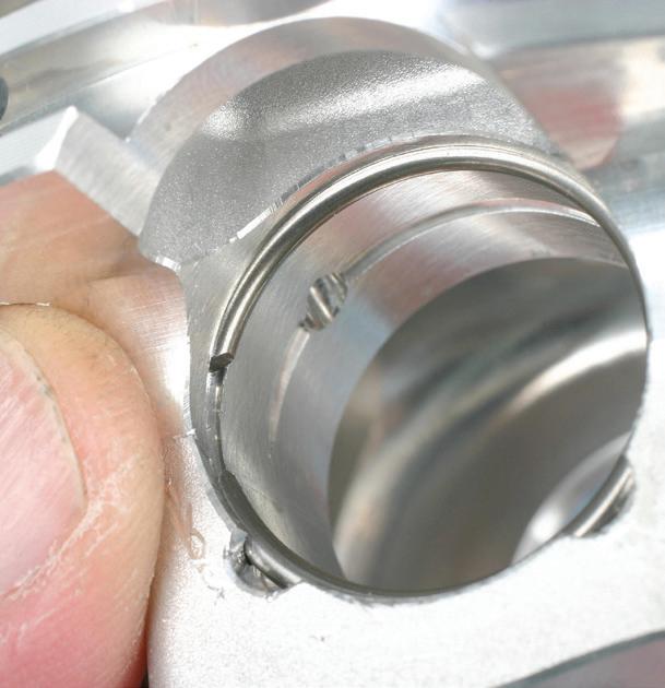
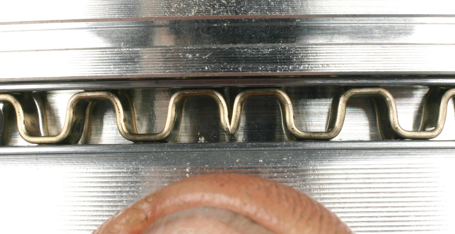
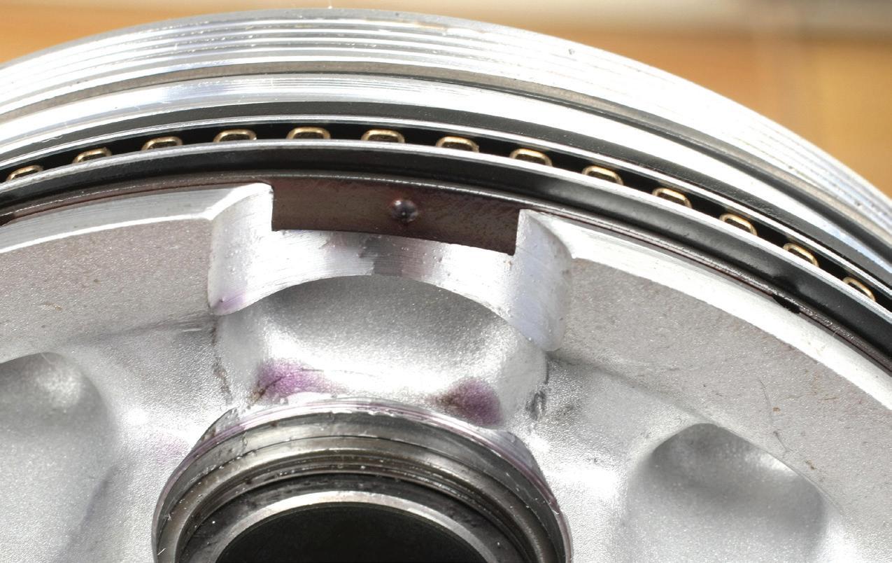
OF an installed wire clip.
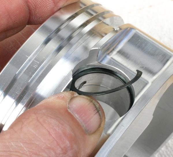
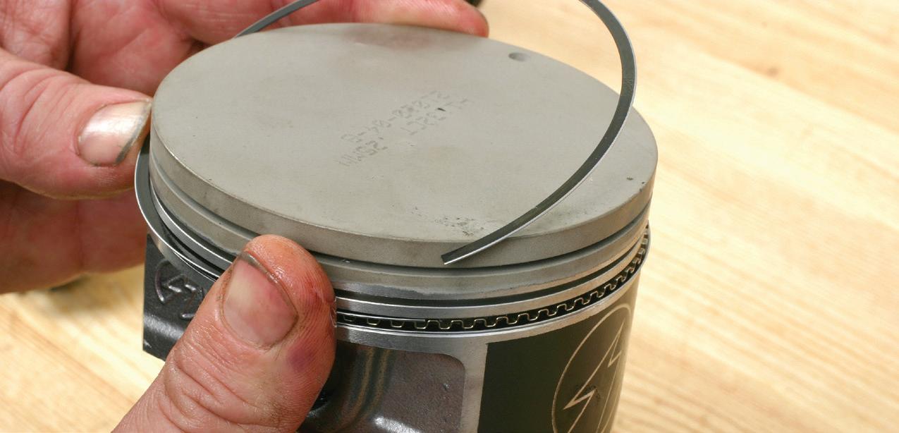
IF THE pistons are supplied with spiral clips, these clips must be gently spread apart to aid installation, then “walked” into place using a small tool such as a flat blade screwdriver. Note that you must use the pin clips that are provided with the new pistons, as groove diameter and groove width will vary depending on application.
BY AUTHOR
tool will be dedicated to a specific bore size. This requires purchasing individual billet compressors based on the engine block’s cylinder bore size (different engines, standard or oversize bores, etc.). Regardless of the tool selected, apply a film of clean oil to the inside of the ring compressor to aid in the rings sliding inside the tool and to the piston rings and skirts.
However, billet style ring compressors are also available that feature a split and a worm-drive clamp, making them adjustable within a given range of bore diameters. Once the appropriate ring compressor is selected (and adjusted for the engine’s bore size), slip the connecting rod/piston assembly through the ring compressor, to a point where the ring package is completely encased in the compressor. Orient the rod/piston relative to the crankshaft’s rod journal. (Refer to a service manual, or make sure that the chamfered side of the rod’s big end faces the crank journal fillet.) Carefully insert the rod into the bore, allowing the piston skirt to enter the bore. While holding the bottom of the ring compressor firmly against the block deck — this is important — push the piston into the bore until the top ring enters the bore. This may require tapping the piston dome with a clean plastic hammer. Be gentle. If excess resistance is felt, stop and inspect. The ring package

ONCE PISTONS have been installed to the connecting rods and all rings are in place, install the upper rod bearing shells into the rod upper saddles. Rod bearings may be dedicated for upper/lower positions, so pay attention to the back of the bearing shells. Install upper bearings to the rod saddles and lower bearings to the rod caps. Contact between bearings and the rod/cap must be clean and dry. Do not apply oil to the saddles or bearing backs. Be sure to orient the piston to the connecting rod correctly. The rod big end may feature a slight chamfer on one side, which must face the crank’s rod journal fillet. The piston may be marked to indicate which side of the piston must face forward.
PHOTO BY AUTHOR
ONCE ROD bearings are installed, apply lubricant (engine assembly lube is preferred) to the exposed bearing surface.
PHOTO BY AUTHOR
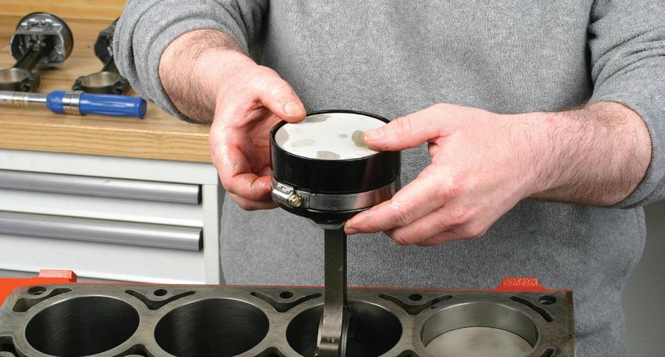
WITH THE rings oriented in the desired clock positions, apply clean oil to piston skirts and rings and slip the piston and rod into the ring compressor, allowing the piston skirts to be exposed past the bottom of the tool. In preparation for piston/rod insertion, rotate the crankshaft to place the intended rod journal near bottom-dead-center.

RING COMPRESSOR tools are available in various styles. The preferred is the billet style, which features a tapered inner diameter and is sized for a specific bore diameter.


Exchange points for discounts, gift cards, gear, and more

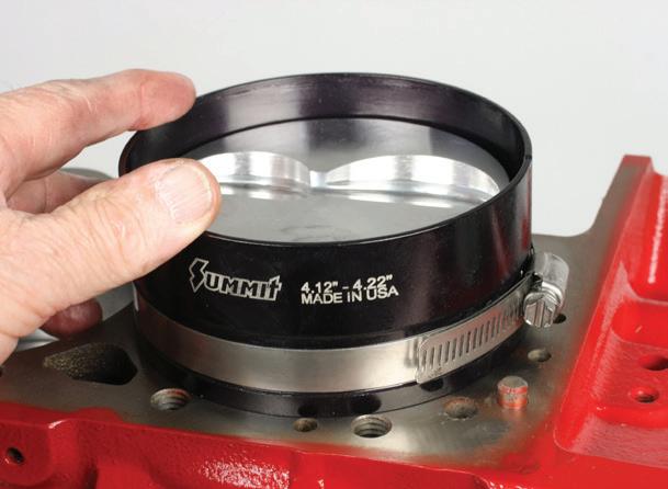
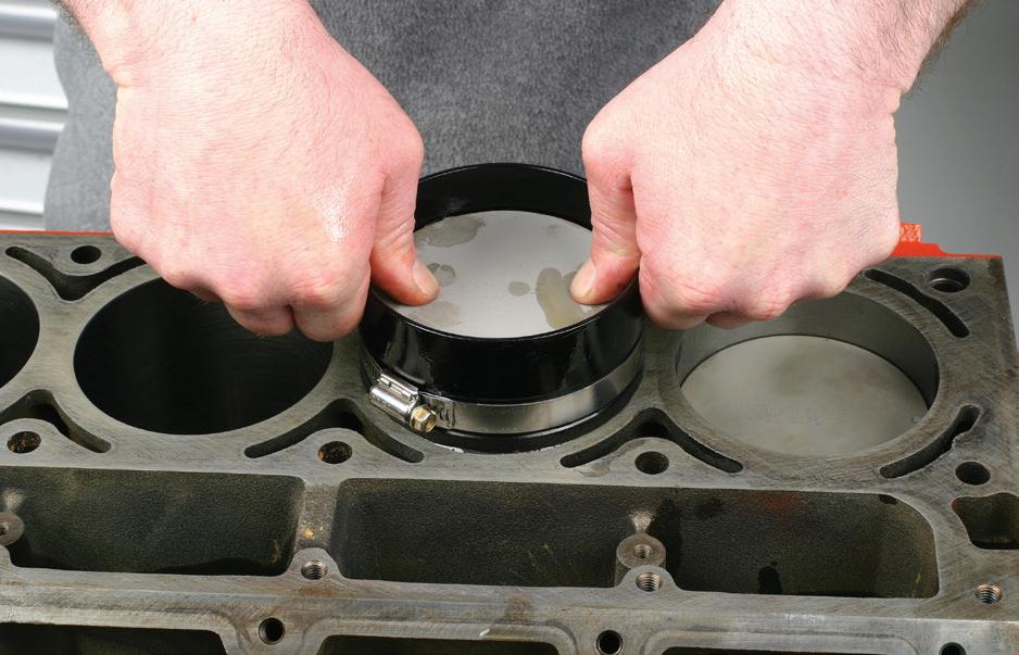
MOST billet ring compressors are one-piece and dedicated to a specific bore diameter, billet compressors are also available that are split and equipped with a worm-drive clamp, allowing the tool to be adjusted within a range of diameters.
PHOTO BY AUTHOR
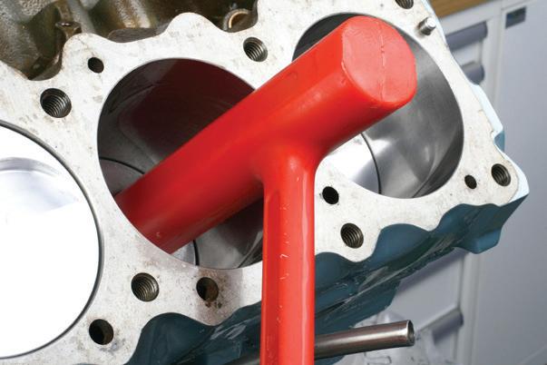
IN SOME cases, you may be able to push the piston down to mate the rod big end saddle to the rod journal; it’s common to need to “nudge” the piston down. Gently tap the piston dome using a clean plastic tool, such as a piston driver tool shown here which features a long hammer head.
PHOTO BY AUTHOR
may need to be compressed a bit more — or the oil ring package may have slipped out of the bottom of the compressor.
Tap or push the piston, while monitoring and guiding the rod big end onto the crankshaft rod journal. Once the rod big end saddle/bearing is squarely seated onto the journal, install the rod’s bearing-equipped cap to the rod big end and tighten the rod bolts to recommended torque. If tapping the piston was required to engage the rings in the bore, closely inspect to make sure that the upper rod bearing shell has not moved or fallen out before allowing rod-to-journal contact.
Once the rod bolts have been tightened, carefully rotate the crank to verify free movement of the assembly. If excess resistance or unusual noise or feeling is found, you may need to remove the assembly to inspect for ring placement.
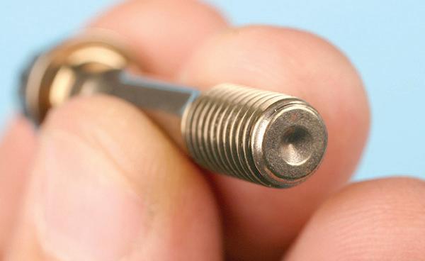
AFTERMARKET connecting rods will feature high strength rod bolts that feature a female dimple at each end, which allows checking bolt stretch.

WHILE YOU can simply follow the OE or aftermarket rod bolt tightening method (torque or torque-plusangle), major aftermarket rod makers provide both torque and bolt stretch data. Torque-tightening plus monitoring bolt stretch provides increased accuracy. If checking bolt stretch, a rod bolt stretch gauge is needed. Place a rod bolt onto the gauge and zero the gauge needle. This provides a reference of the bolt length in its free, static state.
PHOTO BY AUTHOR
Regardless of the application, do not reuse old rod bolts. Always install new rod bolts. When dealing with OE rods and rod bolts, follow the tightening specifications listed in the service manual. When dealing with aftermarket connecting rods/rod bolts, refer to the rod and/ or boltmaker’s instructions. This will usually provide both recommended torque value as well as a maximum bolt stretch value. Most builders prefer to use the bolt stretch monitoring approach, which is more accurate in verifying bolt clamping load.
If using the stretch method, first place a rod bolt onto a dedicated rod bolt stretch gauge. Aftermarket bolts usually feature a female dimple at each end of the bolt. With a rod bolt affixed to the gauge, zero the dial gauge. This provides
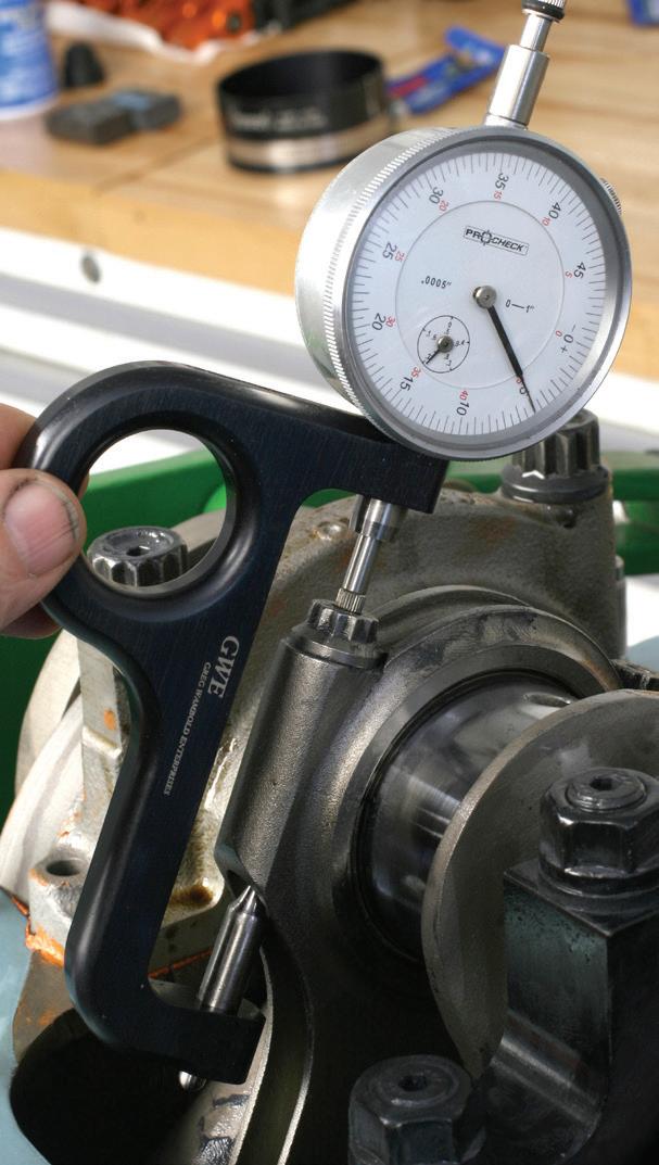
ONCE THE bolt is torqued to spec, the gauge is then placed onto the bolt to reveal how much the bolt has stretched. Rod bolts need to stretch by a few thousandths of an inch in order to achieve clamping load. The spec card supplied with the rods will provide the maximum allowable stretch. If excessively torqued, the bolt may stretch too far, losing its elastic properties.
PHOTO BY AUTHOR
a reference of the static bolt length. After torquing the bolt to spec, install the same gauge to the installed bolt and monitor the amount of stretch that the bolt has experienced. The spec sheet will list the maximum allowable stretch. (Never exceed the max stretch, since this may result in bolt fatigue, exceeding its elastic property.) Using a bolt stretch gauge is time consuming, as each individual bolt must be zeroed and checked after torquing. Do not rely on the zero-setting of the first bolt to be employed for remaining bolts. Each rod bolt must be zeroed on the gauge, since the static length of all bolts may not be identical simply due to bolt manufacturing tolerances.
Repeat the rod/piston installation for all remaining bore locations, checking for crank rotation after each rod/piston installation.
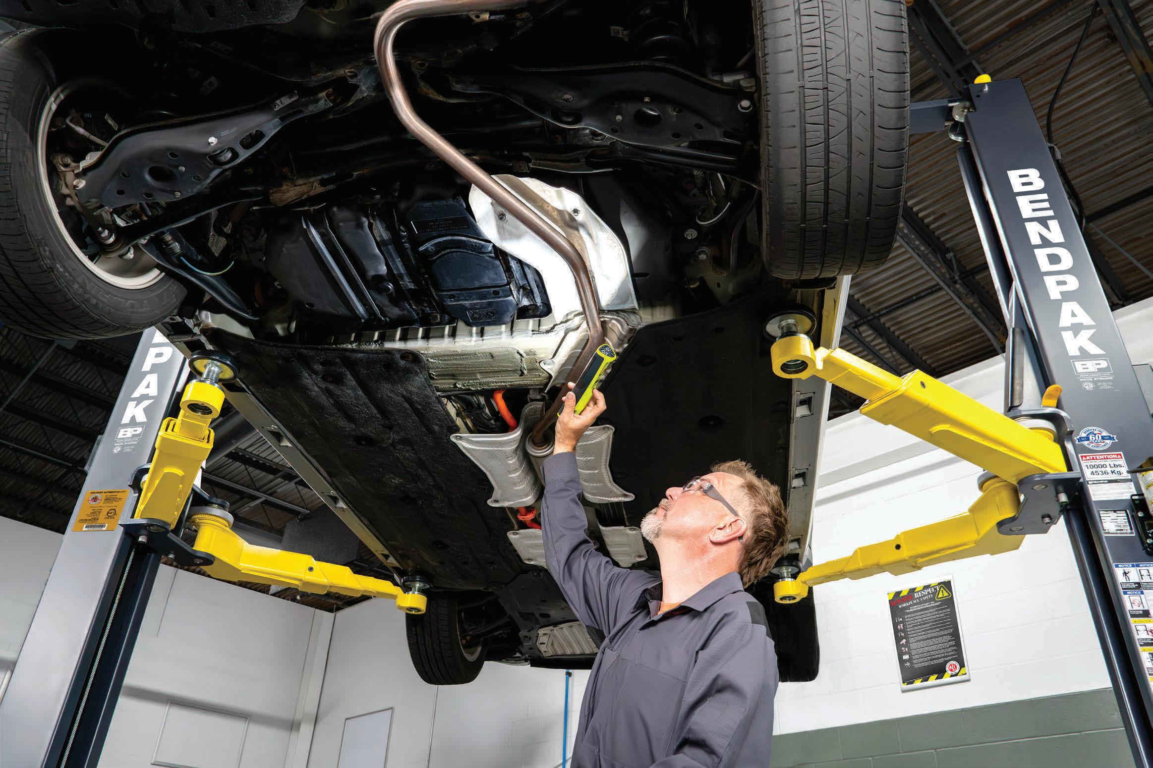
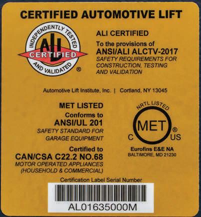


Every day, professionals and DIYers trust their lives to vehicle lifts. But the web is flooded with offshore resellers pushing uncertified, no-name lifts with bold claims — no proof, no oversight, no accountability.
BendPak certified lifts meet ANSI/ALI ALCTV (current edition), the only nationally recognized lift safety and performance standard. Only certified lifts carry the ALI Gold Label and appear in the official ALI Directory, proof of third-party testing and validation.
At BendPak, safety is engineered into every lift. Built strong. Certified tough. And every Gold Label tells the story.
If you’re lifting cars and putting people under them, nothing matters more than safety. Don’t risk it on unverified imports. Get the lift that’s certified. Get BendPak.
Demand the Gold Label. Trust


by Alison Johnson


Around age 2, Cawens Fleurilus spotted men working on broken-down cars on the streets of his native Haiti.
Peering out of gates, Fleurilus watched them take vehicles apart and somehow — magically, it seemed — put them back together and get them running again. He couldn’t yet pronounce the word “mechanic,” but he told his mother that he wanted to be a “be-chanic,” too.
“It was always my dream,” he says. “Looking back, that was the start of an amazing journey. I just hope my story now can inspire others.”
Today, Fleurilus, 34 and a United States citizen, is living his dream. After several years teaching at Atlantic Technical College (ATC) in Florida, where he once was a student himself, he recently began working as a training specialist at Southeast Toyota Distributors in Jacksonville, Fla.
There, Fleurilus develops and delivers advanced technical training to automotive professionals with Toyota, the brand of car he says is most desired by many Haitians.
He travels to teach and visit the 12 dealers that he is responsible for in his district, which covers the southern part of Alabama and the Florida panhandle.
Fluent in English, French, and Haitian Creole, and with firsthand insights on how to overcome adversity with hard work, he has connected with a wide range of students and colleagues to help build diversity in the automotive industry.
For his blended expertise in diagnostics, hands-on repair work and instructional leadership, Fleurilus is the 2025 Motor Age Best Young Tech.
“As soon as we met Cawens, we knew that he was hungry, smart and determined,” says Ryan Walos, technical training specialist supervisor and coach at Southeast Toyota Distributors. “His life story alone showed us that, and he has proven to be all of those things — plus very reliable. He’s an inspiration.”
Fleurilus, the youngest of four children, grew up in Port-au-Prince, the capital of Haiti, and was raised by a single mother. His mom earned enough money
“People usually have a stereotype about the industry like it is not really for smart people. We can help change that.”
— Cawens Fleurilus, training specialist, Southeast Toyota Distributors
as a businesswoman to support him, his three older sisters and a cousin who lived with them, largely by reselling shoes and some clothing that she picked up from markets in Florida and Panama.
Not poor compared to many other Haitians, Fleurilus’ family had safe housing and enough food to eat — but no car. He and his siblings took public transportation to school but sometimes had to walk if political instability or gun violence in the streets shut down buses and taxis.
“It was five or six miles, but all of us kids were in the same boat,” he notes. “We’d walk together and talk and laugh.”
Fleurilus’ father lived in Fort Lauderdale, Fla., where he made occasional visits until 2010. That year, on Jan. 12, a devastating 7.0 earthquake hit Haiti, killing an estimated 300,000 people and destroying homes, buildings and infrastructure throughout Port-au-Prince.


The high school where Fleurilus was due to study for one more year was among the heavily damaged structures. Had the earthquake struck about four hours earlier, he likely would have been buried in rubble in his classroom.
“I live a life of gratitude every day, just because I was there on that day and I am still alive,” he says. “So many others are not.”
At age 19, Fleurilus went to live with his dad, who does landscaping work, originally under a special temporary protected status due to the earthquake. He spoke no English, didn’t know how to drive and began his studies in America in an English for Speakers of Other Languages (ESOL) program with ATC adult education instructors. By 2011, Fleurilus had gotten a driver’s license and mastered enough English to earn a GED. Once he had, he was ready to pursue his childhood dream to improve his life for himself and his family. He credits his mother with encouraging him to follow that passion, even if it didn’t match her original vision of having him be a doctor or lawyer.
Then 21 years old, Fleurilus enrolled


in ATC’s Toyota T-TEN Advanced Automotive Program after meeting with a school guidance counselor, despite the fact that he understood virtually nothing about cars. While not all of his instructors were originally 100 percent sure he could handle the intense curriculum, none of them gave up on him.
“I didn’t know what coolant was,” he recalled. “I didn’t even know how to do an oil change. But that’s what school and good teachers are for. Not knowing about cars or doing repair work on them before shouldn’t stop anyone. You can still go really far.”
As part of ATC’s program, which he completed in 2014 while sometimes working two jobs for income, Fleurilus interned at Toyota of Deerfield Beach. Eventually, that placement was extended to full employment.
Soon promoted to line technician, Fleurilus worked his way up to become a Toyota Master ASE Technician in 2018. Over an eight-year period, he took on important leadership roles, began training new technicians, ensured team consistency, sought out and embraced new responsibilities and earned multiple Employee and Tech of the Month awards.
Ready to move to the next level, Fleurilus completed an associate degree of applied science in automotive technology supervision and management from Broward College while continuing to work full time. He’s earned ASE certifications for automotive service (A1-A8), automobile advanced engine performance specialist (L1) and auto maintenance and light repair (G1).
In 2021, Fleurilus came full circle when he was invited to return to ATC as an au-
tomotive repair instructor under the Broward County School Board. He took a pay cut due to a deep desire to give back to the industry that had changed his life, and to help prepare the next generation of shop technicians. “It felt personal to me,” he said.
As a teacher, Fleurilus emphasized hands-on skills, emerging automotive trends and individualized instruction and mentorship. From that time on, he has bridged the gap between technical proficiency and educational excellence by succeeding at both.
The next year, in fact, ATC’s Graduation Committee asked him to serve as keynote speaker for the graduating class of 2022.
“His devotion to self-improvement demonstrates how hard work, dedication and commitment can transform an individual life into one that led him to helping


others find their own way to success,” ATC staff shared in an article published in “Get There,” a newsletter on continuing and adult education programs in Florida. “His story should inspire anyone, no matter what their accomplishments are.”
That same year, on Aug. 19, 2022, Fleurilus became a U.S. citizen. “It was all proof to me that you can start as the underdog but achieve a lot,” he says. “You can become a leader and a mentor yourself.”
Transitioning into a new job at Southeast Toyota Distributors earlier this year, Fleurilus is now a leader at one of the country’s largest distributors of Toyota vehicles and parts. His job is to develop and deliver advanced technical training to automotive professionals in his district, ensuring they stay ahead of industry standards and innovations.
Colleagues describe him as punctual, attentive, and friendly — a people person who goes the extra mile with a smile on his face.
“Cawens has so much knowledge and a great ability to capture his audience and hold their interest,” Walos shares. “I know him as an instructor, and it’s fun watching him teach, because he’s entertaining and puts off a really good, positive energy.”
In Fleurilus’ eyes, integrity is at the heart of being a good technician. That means doing whatever it takes to get the job done. He typically works nine-hour days, from 7:30 a.m. to 4:30 p.m., but stays late if needed — understanding his limits and earning the trust of his customers.
“It’s OK if you don’t know something,” he says. “It’s OK to ask for help, study, read, learn, and feel a little uncomfortable, because that’s how you’ll get better. And we should do thorough inspections on every car and then work on each one like customers are always watching. You want to show you’re there to help rather than just trying to make money off them.”
As an instructor, Fleurilus has joined the effort to reduce the stubbornly high rate of technician turnover in shops, a major problem across the automotive
industry. Having students learn in classrooms as well as under the guidance of a shop mentor is key, in his opinion.
“Studies have proven that the more trained a tech is, the more likely that tech will stay in the industry,” he says. “We want to make sure that they have a good support system in place in our shops while also providing technical education.”
Widening the potential pool of technician candidates is another strategy. There, Fleurilus believes that having people of many different backgrounds as instructors, shop leaders, and mentors will help.
“I think it’s important for the purpose of representation,” he says. “When you are inspired by someone like you, who has been exposed to the same cultural and social struggles, I believe that level of inspiration has a lot more impact.”
And diversity isn’t just about race or ethnicity; Fleurilus also has been happy to see more women taking jobs in automotive repair. “They are very deep thinkers,” he says. “Not to say males are not, but statistically, the female students perform extremely well on their tests.”
Social media, he continued, can be a powerful tool not just for advertising but for exposing viewers to the “cool” side of automotive repair and the high level of technical expertise required for many positions, particularly given the expansion of computerized systems and electric vehicles. “People usually have a stereotype about the industry like it is not really for smart people. We can help change that.”
In Fleurilus’ specific case, that has meant not only training fellow Haitians to become technicians but encouraging them to take pride in being part of the industry. In turn, he hopes that change in mindset will help the entire Haitian community understand its value.
Finally, Fleurilus anticipates that artificial intelligence could help ease some administrative burdens for technicians — as has been the case in other professions — by assisting with paperwork requirements and enhancing their writing skills, giving
them more time and energy to concentrate on repair work and customer interactions.
“I think of AI as the same way of a calculator,” he explained. “If you know the process, it will help you get the results faster, but you have to use the right formula to get the right results.”
Outside work, Fleurilus last year accepted a volunteer appointment to the board of directors of Broward Community and Family Health Centers, which serves lower income residents. In that role, he influences strategic decisions, contributes industry insights and helps recruit other board members, all to strengthen the organization’s mission to support local families.
Fleurilus and his wife, a fellow Haitian who is a social worker by trade, also are busy raising a 6-year-old son and a 3-yearold daughter. (Both of his children already love toy cars and watching their dad work on vehicles, especially his little girl.) They spend most of their free time together. In addition, Fleurilus enjoys traveling and playing video games.
The family owns three Toyotas: an Avalon, a Highlander and a Solara. “Looking at my kids, the life they have is night and day compared to what I had when I was a child,” he says. His three sisters and mother now live in Boston. He adds: “We all have blessed lives.”
Fleurilus still misses his home country, including its traditional stews and rice and cornmeal porridge dishes with meat, seafood, creamy bean sauces, gravies and spices that draw from African, French, Spanish, and indigenous cultures. He has traveled back to Haiti with his wife and hopes to take his kids there one day if the trip feels safe.
Meanwhile, now miles away from his days of watching street “be-chanics” as a wide-eyed boy, Fleurilus only wants to keep moving up in his company and industry.
“I’m always looking to grow and to help others grow,” he says. “We have an outstanding culture at my work for which I am very thankful. I’ll never forget how fortunate I am.”


This newsletter, a co-branded project between ASE and Motor Age, includes the latest Motor Age technical articles and news, as well as videos. You’ll also get ASE content, interviews with World Class Technicians, and a new test question of the week in each newsletter.

Sign up to receive the ASE Certified Tech Edge newsletter every Wednesday.


$10,000+
Vendors have partnered with VehicleServicePros.com to offer you a chance to win prizes. Vote for up to five products each day, increasing your chances for those particular prizes. Visit gpg.vehicleservicepros.com to view all prizes and enter to win Sept. 1 – Oct. 31, 2025. Winners will be notified by November 15th. Good luck! DON’T WAIT! GIVEAWAY
• Be sure to stop back daily to improve your chances of winning. HOW TO ENTER
• Visit gpg.vehicleservicepros.com to view all prize details and enter to win.
• To enter, check boxes on the entry page for your top five products.


BY JEFF TAYLOR

THE START-STOP SYSTEM isn’t new anymore, but it continues to confuse both drivers and technicians alike. A customer complaint of “my car doesn’t shut off at stoplights anymore” is something many shops see frequently. With so many OEM-specific systems, inputs, and activation conditions, it’s no wonder these systems cause diagnostic headaches. But with a solid understanding of how StartStop works and more importantly, why it might not be working, we can narrow down the root cause faster.
Start-Stop systems are designed to reduce idle emissions and improve fuel economy by shutting down the engine when the vehicle is stopped and restart-
ing it when the brake is released. They have been installed in nearly every new platform since 2015. That’s the easy part. Behind the scenes, the system is using data from multiple sensors and modules to decide if it’s safe to shut down the engine. Battery voltage and temperature, brake vacuum, cabin HVAC demand, gear choice, and even the position of the hood switch all play a role.
Idle Stop, ESS and Auto Stop are simply different names for the same system. It’s worth noting that not all automakers use the same name for these systems. Honda calls it Idle Stop, Jeep uses ESS (Engine Stop Start), Mazda has i-Stop. While the function is similar across brands, the acti-
vation logic and naming can confuse both techs and drivers, especially if they’ve just switched vehicles.
The Battery Start-Stop vehicles place extra demands on the battery, especially with how often the engine shuts off and restarts in traffic. Standard flooded batteries just aren’t built for that kind of cycling. That’s where EFB (Enhanced Flooded Batteries) come in. EFBs are basically beefed-up versions of standard lead-acid batteries. They’re built to manage the added stress of Start-Stop operation. You’ll usually see EFBs in base model Start-Stop vehicles that don’t have a lot of extra electronics but
still need to crank the engine more often than normal.
AGM (Absorbent Glass Mat) batteries are the next level up. These are designed for vehicles with heavier electrical loads or systems like regenerative braking. They recover charge faster, tolerate deeper discharges, and hold up better under heat and vibration. Since they’re sealed, there’s no worry about leaks, which is why they can be mounted in less traditional locations like under the rear seat or in the trunk.
Other vehicles go even further by using two batteries: one to start the engine and another to handle accessories when the engine’s off. This setup keeps everything running without putting too much strain on a single battery. Dual batteries aren’t the only power source that have been used to prevent flickering screens, dropped Bluetooth connections, or glitches in the HVAC controls. Capacitors have been used but most manufacturers are using DC-to-DC convertors to keep key electrical systems alive when the engine shuts off at a light.
The DC-to-DC converter takes power from the 12V main battery and regulates it down to support sensitive electronics like the instrument panel, radio, and control modules. And when the engine restarts, it helps smooth out the transition so there’s no voltage spikes or drops that could interrupt systems. The in-rush starter current can easily reach 800 amps, and voltage can drop to 11.5V while restarting a V8, and these current and voltage fluctuations need to be smoothed out.
Some GM models equipped with StartStop can set a P3055 (DC/DC Converter Output Voltage 1 Performance) in the PCM. This DTC could be a misconfiguration issue, requiring reflashing and setup procedures, or it could be the Power Supply Transformer has failed.
On the 2018 Honda Odyssey Elite with Start-Stop, a dedicated 12-volt battery cooling fan is used to help manage battery temperature. The PCM controls the
fan based on data from the 12-volt battery sensor mounted on the negative battery terminal. This sensor watches battery voltage, charge and discharge current, and fluid temperature. If the battery gets too warm, especially at low vehicle speeds, the fan kicks on to protect it from heat-related damage. If the fan fails or communication is lost between the PCM and battery sensor, the system can trigger DTC P16E7. There’s also a failsafe that forces the fan on if intake air temperature hits 95 degrees Fahrenheit or higher, even if battery sensor data is missing.
On a regular vehicle without Start-Stop, the starter motor might get used about 50,000 times over its lifetime, basically just from starting the engine once or twice a day. But in a vehicle with StartStop, that number can climb to well over 500,000 starts, especially in city driving or stop-and-go traffic. A regular starter wouldn’t last long in a Start-Stop setup, since it just isn’t built for that kind of constant use. That’s why these systems use a much tougher starter. They’re built for the job, with beefed-up internal parts like heavier brushes, reinforced bearings, better windings, and in many cases, a gear-reduction drive to handle the extra torque and frequent cycles.
The engagement mechanism is faster and quieter too, which helps smooth out the restart when the engine kicks back on. The housing, solenoid, and even the cooling design are often upgraded to deal with the extra heat and vibration from all that added use. Basically, it’s not just a better starter, it’s a completely different class of component.
A common Toyota starter motor related DTC that we see in the service bay is the DTC P1542:00, which shows up when the engine doesn’t restart fast enough during a Start-Stop event. Specifically, it sets when engine speed stays below 400 rpm for more than 1.38 seconds during a restart.
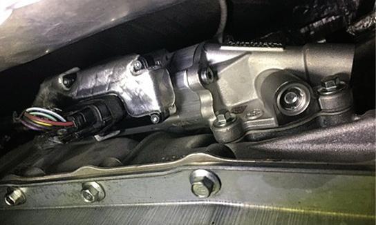
transmis-
fluid pump on a 2017 Ford F-150 equipped with the 2.7L EcoBoost and Start-Stop system. This pump maintains line pressure in the transmission during engine-off events, allowing for smooth gear engagement when the engine restarts. If this pump fails, the vehicle may experience harsh shifts, delayed engagement, or Start-Stop system faults. A scan tool may reveal related DTCs or pressure drop data during Idle Stop.
PHOTO BY AUTHOR

PHOTO BY AUTHOR

THIS START-STOP OFF button, located beside the Drive Mode selector, allows the driver to manually disable the Start-Stop system. Once pressed, the system will not shut off the engine at idle until the vehicle is restarted or the button is pressed again.
PHOTO BY AUTHOR THESE FOUR Start-Stop dash icons show various system statuses. Top left: The system has been manually turned off by the driver. Top right: The system is active and will shut the engine off when conditions are met.Bottom left: Start-Stop is temporarily unavailable due to system inputs (like battery SOC or HVAC demand).Bottom right: The system is automatically disabled due to a fault or blocked condition.
The usual suspect here is a weak or failing battery, but it’s not always that simple. Low fuel pressure, injector faults, or even a dirty throttle body can also delay the restart just enough to trigger this code. The system expects the engine to fire up fast and smoothly. If it doesn’t, even for a second and a half, it’ll let you know.
In a Start-Stop vehicle, the alternator must do more than just keep the battery charged. It needs to recover energy quickly and handle frequent charging cycles without burning out. When the engine restarts, it’s expected to bring the battery voltage back up quickly and support things like power steering, HVAC, and infotainment, which all keep running while the engine’s off. Most Start-Stop systems use an upgraded high-output alternator combined
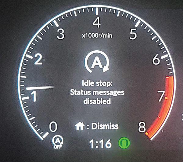

with a smart charging system that can ramp up output fast after every restart. Some systems also use what’s called a brake energy regeneration alternator, which increases charging during deceleration.
A common complaint with Start-Stop systems is the drop in cabin comfort when the engine shuts off, especially on hot or cold days. Since most of these systems use belt-driven A/C compressors (today’s hybrids typically use an electric compressor), there’s no compressor operation when the engine isn’t running. To work around this, manufacturers have made HVAC system upgrades specifically for Start-Stop vehicles. A common solution is the use of a cold-storage evaporator that uses a phase change material (PCM), or similar heat-absorbing material built into the evaporator core to store cooling capacity while the engine is running. This cold storage helps maintain air temperature during short engine-off periods. Some systems also adjust blower speed or delay the StartStop event entirely if interior temps start to rise too quickly.
On the heating side, it’s the opposite problem. If the engine shuts off, so does coolant flow, and that can leave the cabin without warm air in colder weather. To avoid this, many Start-Stop vehicles use electric coolant pumps to keep warm coolant circulating through the heater core while the engine is off. This helps maintain cabin heat during idle-stop events and avoids triggering an auto-restart just to restore heat. Failed electric coolant pumps are common as vehicles age. The Ford “Coolant Pump A” is part of the high-temp loop in Start-Stop, hybrid, and plug-in hybrid systems. It keeps hot coolant flowing to the heater core when the engine shuts off, and if it fails, you’ll see DTCs like P2600–P2603 for circuit or performance faults.
The HVAC system is also tied into the Start-Stop control logic. If the cabin is too hot or too cold, or if the defrost is active,
the PCM may block engine shutdown completely. This is why you’ll sometimes notice the engine stays running in traffic, even though the Stop-Start system is enabled. The vehicle is putting occupant comfort first.
Engines in Start-Stop vehicles need internal upgrades to handle the constant restarting. Low-friction coatings on pistons and polymer or tri-metal layers on crankshaft and other engine bearings protect against dry-start wear. The starter ring gear and flywheel are also reinforced to handle the higher number of engagements.
The transmission needed modification as well. One key change is the use of a low-leak valve body. In most automatics, transmission fluid pressure drops quickly once the engine shuts off, which can lead to a slight delay or harsh engagement when the engine starts again. In a Start-Stop vehicle, the valve body is redesigned to hold clutch pressure longer during engine-off periods so the transmission can re-engage smoothly and instantly.
Another change is the addition of an auxiliary electric transmission fluid pump or a Start-Stop accumulator. These devices maintain transmission line pressure and keep the torque converter filled when the engine is off.
Don’t Skip the Basics
One of the most common complaints with Start-Stop systems is “it’s not working.” But in most cases, that’s not because something’s broken, it’s because something is intentionally preventing it from working. These systems are picky, and there are a lot of conditions that can shut them down quietly in the background.
Start by checking the battery or batteries. It’s surprising how often this gets missed. Start-Stop systems aren’t designed for your typical flooded battery. They need AGM or EFB types that can handle repeated deep cycling. And it’s not just about


From grungy transmissions to grimy engine blocks, nothing cleans better than Ranger’s signature stainless steel line of aqueous cleaning and degreasing systems. Durable 304 stainless steel construction is resistant to harsh chemicals and delivers the strength to endure years of hot-washing with minimal upkeep. All models feature twin heaters for quick startup, large-volume solution tanks, oil skimming system, low-water shutoff, friction-drive turntable system and gasket-free door. Beauty combined with strength, performance and durability. Order now at www.bendpak.com/wash


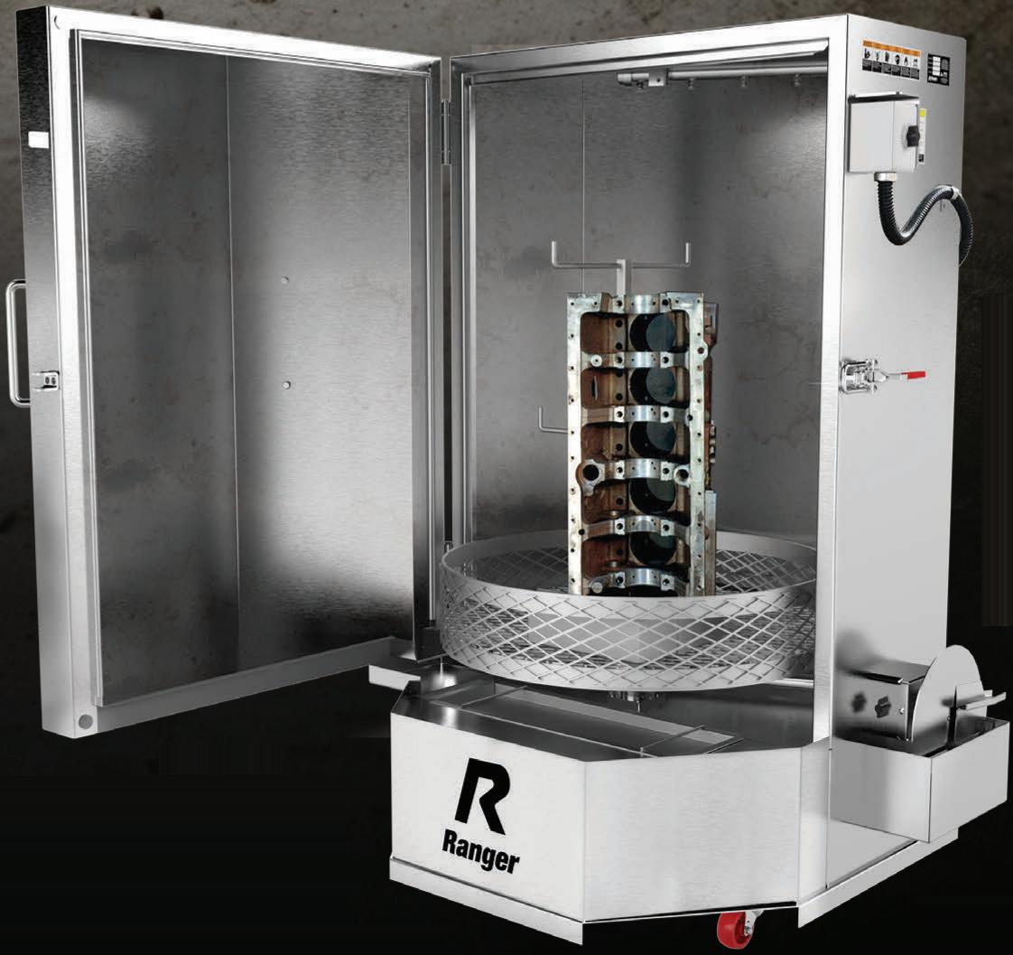


THIS SCAN tool screenshot shows a stored DTC P057F on a Jeep, which stands for “14 Volt Battery State of Charge Performance.” This code often points to a degraded main or auxiliary battery, or a fault with the Intelligent Battery Sensor (IBS). This DTC commonly disables the Stop-Start system until the battery is tested, replaced, and the code is cleared.
PHOTO BY AUTHOR
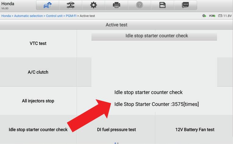
number of times the starter has been used during Stop-Start events. In this example, the counter shows 3,575 activations. Some manufacturers track this data to monitor wear, and in some cases (like Toyota), excessive counts can influence system operation or trigger DTCs.
PHOTO BY AUTHOR
having the right battery; it also needs to be registered to the vehicle. Skip that step and you’ll get incorrect state-of-charge readings, which lead to false system disables.
A common DTC on Jeep vehicles is P057F: 14 Volt Battery State of Charge Performance. This code can be set when the PCM receives a message from the Intelligent Battery Sensor on the CAN C bus that the battery state of charge is outside the calibrated range. The most common resolution is the replacement of the battery with the correct size and model and then clearing the code.
We had a 2019 F-150 5.0L in the shop recently. The customer had just had the battery replaced elsewhere, but the StartStop still wouldn’t activate. Turns out the Battery Management System (BMS) reset was never done. Once we completed the
reset using a scan tool, everything worked fine again. If your scan tool won’t reset the Ford BMS, you can reset it manually. To reset the BMS, turn the key to the “on” position without starting the engine (or press the start button without your foot on the brake). Flash the high beams five times, then press the brake pedal three times. If the battery light starts flashing, the reset is working. Once it stops, cycle the ignition off and back on to confirm.
Ford systems are sensitive to that BMS logic: if the reset doesn’t happen, it could overcharge or undercharge the battery or disable the Start-Stop to protect it.
The Jeep Cherokee is another good one to watch. We’ve seen several come in with complaints about the ESS system not functioning. In most cases, the problem is traced back to a faulty hood latch switch.
It doesn’t set a DTC, but it tells the system the hood is open which is enough to suppress the Start-Stop system every time. A quick check with a scan tool or jumper at the switch connector saves a lot of wasted diagnostic time.
Here’s another common Start-Stop issue: after battery replacement or certain repairs, the system needs time to relearn the battery State of Charge (SOC) and re-establish voltage references. GM requires at least a 75% SOC for the system to operate correctly. For a vehicle to relearn the battery SOC, it can take up to three or four consecutive hours of key-off time, with the vehicle undisturbed and drawing less than 100mA (Sleep Mode). If the customer or tech opens the door or hood during this period, the timer resets and the process is restarted. It’s important to share this information with the customer after a battery replacement to prevent return visits and concerns.
When testing batteries, don’t rely on an old-school battery tester. EFB and AGM batteries behave differently, especially under partial charge or load. If your tester doesn’t support testing these types of batteries, it might falsely pass a failing battery. This is a very common issue.
Another layer to understanding StartStop systems is knowing why they’re being blocked from operating because more often than not, that’s exactly what’s happening. These systems monitor a long list of input conditions, and if even one of them falls outside the accepted range, Start-Stop is inhibited. What makes it tricky is that most of these won’t set a DTC. The system is doing exactly what it’s supposed to, but the driver sees it as a failure. You might be chasing your tail if you’re not looking at the right data. Inputs like hood switch status, driver seatbelt, brake pedal sensors, door position, brake vacuum, cabin temperature,


battery temperature, recent gear selection, and HVAC mode are all part of the equation. Even steering angle, fuel level, or open circuit draw can be used to block Start-Stop, depending on the OEM. And these aren’t always handled by the PCM. In many cases, the Start-Stop logic may live in another module, like the BCM, the instrument cluster, or the HVAC module. This is why a full module scan is needed to address many of today’s issues, not just Start-Stop.
Most good tools will give you a breakdown of Start-Stop enable criteria, showing which conditions are currently met and which are not. It’s one of the most useful pieces of data when diagnosing these systems. If Start-Stop won’t engage and you see that “hood switch not closed” or “defrost active” is flagged, that’s your reason right there. We’ve seen plenty of vehicles come in with no codes, no warning lights, just a simple logic block that gets overlooked.
These systems rely heavily on clean communication between all the major mod-
ules. The PCM may oversee the engine restart, but it needs valid inputs from the BCM, TCM, HVAC, and other control modules. If there’s a communication glitch on the CAN network, say a momentary dropout between the cluster and the BCM, the system might quietly disable Start-Stop with no visible warning, but also set a U-code DTC. On platforms with more complex electrical architectures, like those with DC-DC converters or dual batteries, even a low-level communication error can shut things down.
Also, watch for non-OEM accessories or updates. Infotainment upgrades, remote starters, and even older dash cams that cause parasitic draw can interfere with Start-Stop readiness or prevent proper battery status relearn.
One more thing to keep in mind: Start-Stop behavior can change after a software update. Several OEMs have issued TSBs to revise Start-Stop logic, sometimes to address nuisance restarts or improve comfort. If a system suddenly starts acting differently
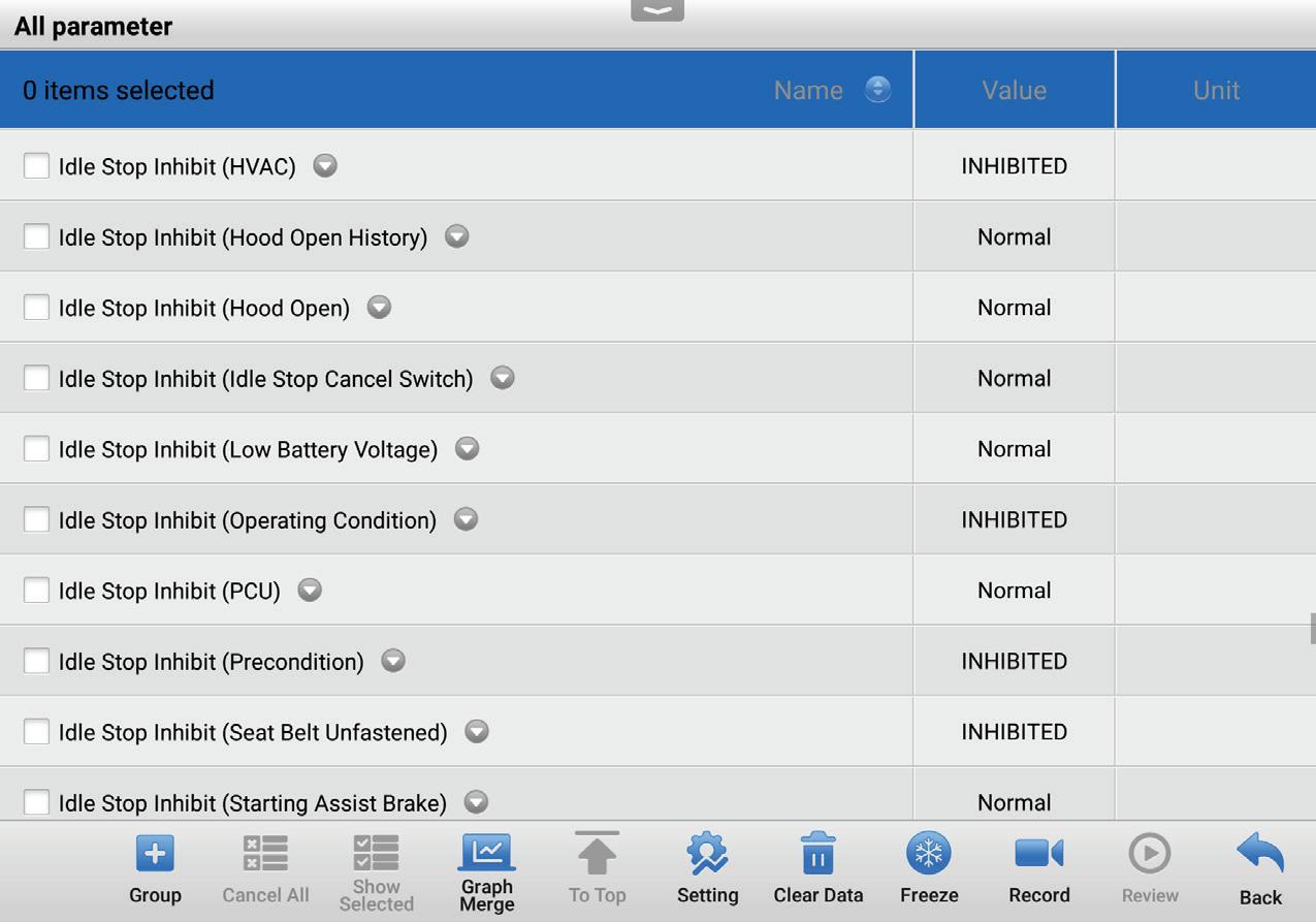
after a dealer visit, double-check for recent reflashes. It’s also worth verifying whether the customer has updated modules that affect sleep cycles, especially in newer connected vehicles, that are getting OTA (Over the Air) updates.
Finally, a quick word on communication. A lot of drivers hate Start-Stop. Some disable it manually every time they start the vehicle. And for them, relief may be coming, because while working on this article, news surfaced that the EPA may no longer require Start-Stop systems on future vehicles. But for other drivers who don’t mind the system, they may feel it isn’t working when it’s just inhibited. Take a minute to explain the system and what conditions might prevent it from working. That one-minute conversation can save you a comeback and a lot of confusion. Start-Stop complaints are often the result of misunderstood conditions not mechanical failure. By understanding how the system is supposed to work and what will inhibit it, you can approach diagnostics more confidently. Always verify battery health and registration. Don’t overlook basic inputs like hood switches, brake sensors, or parasitic draw. And when in doubt, take a few minutes to study the OEM criteria for Start-Stop activation. That’s where the answers usually live.


• Today’s aftermarket demands more from your shop—and your tools. The Launch X-431 Throttle V gives you the edge with advanced diagnostics, step-by-step repair guidance, and the latest vehicle protocol coverage. It’s more than a scan tool—it’s a productivity engine.
• For technicians, that means confidence on every job, fewer comebacks, and guided functions that get repairs done right the first time.
• For shop owners, that means better bay efficiency, stronger margins, and a tool that adapts as the market changes.
ECUs are not smart at all. They are only as good as the inputs they rely on.
BY BRANDON STECKLER // Technical Editor
A CLIENT OF MINE WAS FACED WITH a 2008 Jeep Wrangler with a 3.8L engine. For unknown reasons, the engine was previously replaced with three different units, and at least one replacement PCM. Upon receiving the request for help, they were pursuing two existing DTCs:
• P0340 “Camshaft position sensor circuit”
• P0344 “Camshaft position sensor intermittent”
Initial Analysis
After preliminary research of the DTCs, the service information reflected that the existing fault could be caused by either a circuit issue or a mechanical fault (Figure 1). Considering I’m more than 1,500 miles away, I have some concerns with the fact that the engine wiring harness was manipulated so many times. The potential for connector/terminal/wire/ component damage grows more likely with each engine replacement. With that a few things came to mind and I first had the tech send me pictures of the CMP sensor pigtail/wire harness (Figure 2).
I was not surprised to see the damaged and poorly repaired wiring harness. But here’s the question,“Is this the root cause of the fault or is this just a botched attempt to fix it?” The good news is that we can clear the DTCs and they will return within several seconds of starting the engine. In other words, we have no problem reproducing the fault.
It’s obvious the tech was not comfortable with proper wiring repair, but I have
WELCOME BACK TO ANOTHER EDITION OF “THE DATA DOESNT LIE,” A REGULAR FEATURE, WHERE I POSE A PUZZLING CASE STUDY.

(F856) 5-VOLT SUPPLY CIRCUIT OPEN (F856) 5-VOLT SUPPLY CIRCUIT SHORTED TO GROUND (K44) CMP SIGNAL CIRCUIT SHORTED TO VOLTAGE (K44) CMP SIGNAL CIRCUIT OPEN (K44) CMP SIGNAL CIRCUIT SHORTED TO GROUND (K44) CMP SIGNAL CIRCUIT SHORTED TO THE (F856) 5-VOLT SUPPLY CIRCUIT TONE WHEEL/PULSE RING CAMSHAFT POSITION SENSOR POWERTRAIN CONTROL MODULE (PCM)
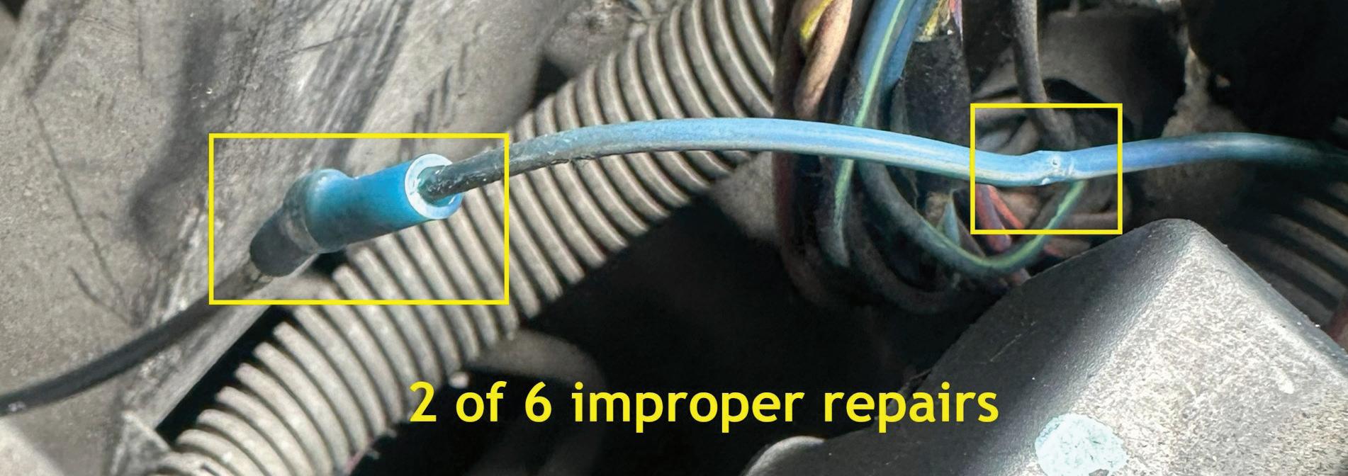
a job to do as a tech support data analyst. So, instead of fumbling around with subsequent attempts, I chose to instruct him to leverage the multi-trace lab scope and capture data downstream from the botched wiring repairs. The best place to do this was at the back side of the PCM
connector. I advised him to use pierce probes rather than back probes in a situation like this. Back probes could in fact enhance the connection at an otherwise poor fitment issue in a connector. He captured the CKP and CMP signals for me to review. I analyzed the data files
and zoomed in to an area that I could compare to a sample from a knowngood vehicle (Figure 3). Clearly, there is a fault, but is it internal to the engine or circuit related?
With all the information in front of us, and the desired information not yet obtained, we are faced with deciding how to proceed. Here are some bullet points of

PHOTO BY AUTHOR

what we know to be factual, and I will ask all of you, diligent readers, for your input on what they mean to you, collectively:
• CMP-related DTCs exist and are current
• Fault could be circuit or mechanically related
• Obvious damage to harness and connection exists and must be rectified
• An underlying fault may still exist once the circuit has been repaired
Given this information, what would you do next?
1. Fix wiring first and re-examine
2. Replace the CMP sensor and re-examine
3. Condemn the CMP reluctor for improper configuration
4. Inspect CMP reluctor with a borescope

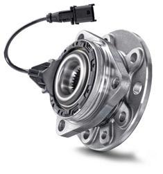

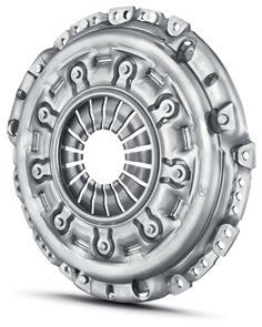
Experience Schaeffler’s reliable OEM repair solutions, engineered for quality and efficiency. Maximize uptime, reduce costs, and ensure easy maintenance with our durable components.
www.vls.schaeffler.us

BY BRANDON STECKLER // Technical Editor
What would you recommend doing next, given the data bullet points in the previous challenge?
1. Condemn intake valve integrity for cylinder No. 1
2. Condemn exhaust valve integrity for cylinder No. 1
3. Condemn engine for multiple cylinders’ valve integrity
4. Inspect for a bank-to-bank breathability issue
For those of you who chose answer No. 4, congratulations! In combination, the pattern of the cranking intake vacuum trace and the engine configuration alluded to a variation in breathability. We have to keep in mind that even though the
PCM was counting misfires consistently for cylinder No. 1, a threshold must be crossed to set a DTC. The nature of the intake pattern suggested an inspection of a bank-to-bank breathability of would-be time better spent.
The next logical test would be the inspection of the timing components. Even though this was not carried out, a multitrace scope capture comparing CMPs to CKP would yield the conclusive data we needed to infer a timing issue. Simply triggering from an ignition sync would stabilize the pattern and allow us to see a correlation between CMPs and CKP as varying, even if the chain had not yet jumped a tooth (or several teeth).
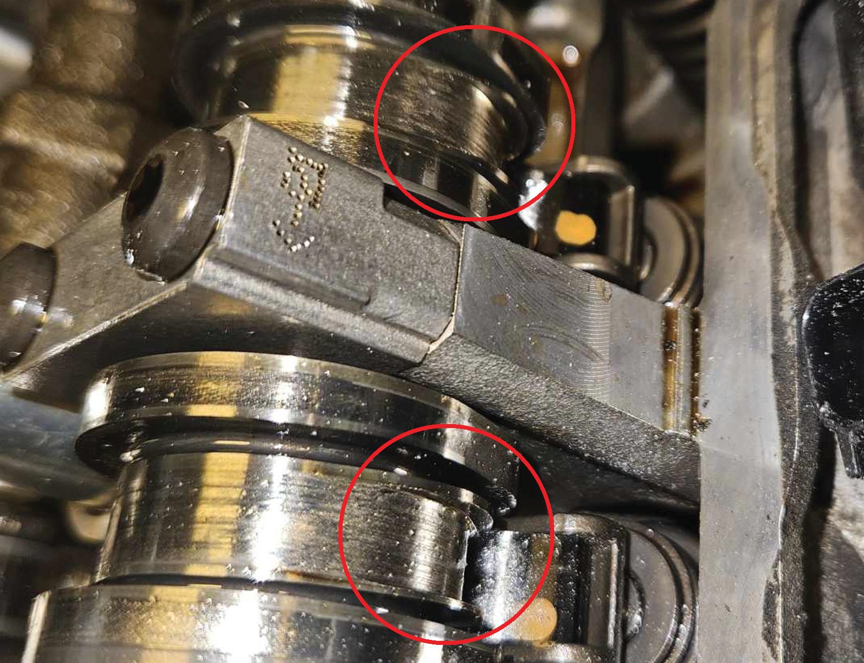
My friend Rick chose the simple process of removing the valve covers for inspection of the valvetrain. Not only did he discover that timing was still correct, but he also discovered the root cause of the fault. The intake cam lobes were significantly worn, leaving all three cylinders of bank No. 1 deficient of air, under higher rpm conditions (See image)
Answer No. 1 is incorrect. Although cylinder No. 1 was suspected of being the sole malfunctioning cylinder, the data proved the fault was a bank-to-bank issue.
Answer No. 2 is incorrect for the same reason that answer No. 1 was incorrect.
Answer No. 3 is incorrect. Although replacement of the engine is a more prudent step in many situations, (especially this featured engine platform), it is not the correct diagnosis. If that were the case, replacing the engine for every mechanical fault present would be called for. Obviously, this is not cost-effective for the client.
Be sure to read the next Motor Age issue for the answer to this month’s challenge and what was discovered!

BRANDON STECKLER is the technical editor of Motor Age magazine. He holds multiple ASE certifications. He is an active instructor and provides telephone and live technical support, as well as private training, for technicians all across the world.


PERFECT FOR TIRE SHOPS


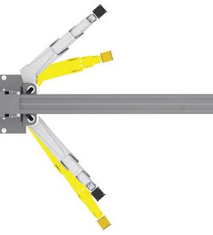

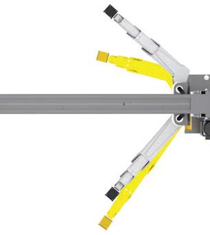


The BendPak 12AP-SRT short-rise two-post lift cost-effectively improves tire shop productivity and efficiency while mitigating risk. With 12,000 pounds rated capacity, massive wingspan that reaches most OEM lifting points, and BI-METRIC™ arms to suit virtually every vehicle lifting requirement – symmetric or asymmetric. The 12AP-SRT can raise 99 percent of cars, SUVs, and trucks to a comfortable working height much faster (and easier) than a set of jacks. Its single-point safety lock system, super-strong automatic arm restraints, and limited max lifting height of 47 inches deliver superior peace of mind. The short 93.5inch columns offer lower product, installation, and maintenance costs, plus a cleaner floorplan. Check out the full line of BendPak lifts at bendpak.com or call us at 1-800-253-2363

When it comes to figuring out what is wrong, you must know what is right.
BY CRAIG VAN BATENBURG

THEORY IS A MUST, but it will never replace experience. You need both. xEV is a new term that includes all types of high voltage vehicles. Mastery of this highly skilled profession is never ending. We are no longer a “trade.” Reaching the top of your career happens when your ability to analyze data and arrive at a diagnosis fixes the root problem.
Van Batenburg’s Garage was started by me at age 26. I hired many high school and college students and graduates. ACDC — my current business — still does today. Those years have allowed me to observe many new technicians. The ability to use critical thinking is paramount. That can

be fostered in schools, if the instructor incorporates critical thinking into their method of instruction. Sometimes the best advice to a technical question, when you are troubleshooting a difficult problem, is to “figure it out.” Once you can figure it out, after the scan tool and flow charts have failed you, the mastery of the systems used in xEVs will be yours. Think it through, using logic and reason. Stay at it, but take a break when you get frustrated. If you are getting nowhere, make sure you have done a thorough job at the basics. This is the most challenging part of your job and also the most rewarding. Don’t quit.
Your brain is a computer of sorts. It stores information, retrieves it later on, calculates basic math, and helps form words so you can speak. Your brain can analyze data and make decisions. Brains exist in all mammals, but there is one thing we can do that other mammals cannot do, and that is pause and think things over. Other creatures work by instinct, and humans can also do that, and at times it works. Analyzing, mak -
ing a diagnosis, and repairing an xEV is a process that cannot be done by instinct or guessing. You may look something up on the internet and try replacing a part and get lucky in that it fixes the xEV. But will it stay fixed? Did you get to the root cause or did you merely relieve a symptom, only to have the problem return? To get to a level of mastery in this world of high voltage vehicles, you will need to keep learning forever. If you are not a lifelong learner, the technology will pass you by. If the codes are accurate, to the degree that the software engineers were able to program the xEV, and the scan tool doesn’t get you to the fix, more study and a deeper look are needed.
To start any diagnostic procedure (excluding the managerial part of getting the customer to pay for the time), here is a checklist in the order ACDC feels it should be done. Note: The order may be slightly different in some shops.
1. Have the customer prepare the xEV for service. Here is a checklist for the car owner:
• Unless the fuel tank is leaking, the vehicle needs to have at least a half tank of fuel. And/or, ensure the xEV has a
sufficient charge in the HV pack for road testing and diagnosis.
• The driver has given you the key fob he or she normally uses. (Figure 1).
• The driver left the special “lug nut“ socket on the passenger seat.
• If there are “aftermarket electrical devices” installed on the xEV, you are aware of them.
• You have a history of the xEV, and know if it’s a flood damage vehicle, was totaled in a crash, was in an accident and repaired at a body shop, etc.
• The owner has removed all personal items from the vehicle, including the frunk and trunk.
• The owner brought the xEV in free of trash and excessive dirt.
2. You have read the repair order carefully so you understand the complaint.
3. Verify the complaint. This may require a road test.
4. Do a thorough visual inspection.
5. Request copies of previous repair orders related to that issue, or issues, if there is more than one complaint.
6. Before getting too far into the diagnostics, research online for any recalls, technical service bulletins (TSBs), software updates needed, etc.
I assume you are or will be a Master Technician (Figure 2) on conventional vehicles and have been trained and/or are being trained concurrently on electric vehicles.
If an xEV has been worked on by anyone who was not properly educated to work on the vehicle you have in front of you, or if it has been rebuilt from a wreck, has been involved with a flood or has been modified, the odds of a successful repair will be much less than a vehicle where you are the first one to attempt the repair.
As an independent shop owner for over 25 years (1977 to 2004), I learned that the car owner is an important part of the pro-
cess. Interviewing the driver/owner is required to discover the repair history, type of driving, and environment that the xEV was subjected to. Technicians at Van Batenburg’s Garage (Figure 3) (my former independent Honda/Toyota shop) engaged with the vehicle owners when the description they gave us did not match the vehicle’s symptoms. If the money part of the repair process was taken care of, the tech would call the customer to ask questions we failed to ask, or did not know to ask, at the time the vehicle was dropped off for repair.
A technician named Jeff, who I know well, confided in me that if a vehicle came in and it was one he wasn’t that familiar with, he studied the systems the night before. He felt guilty that he wasn’t available every night as he is a father and husband for his family. I explained that this extra study is how he got so good at his job and bought a house. It takes a lot to excel in this profession, but the rewards are there. The road to a successful diagnosis and repair can take many turns.
A few lessons to learn early on are:
• Don’t guess at what is wrong — test, test, test.
• Know how to read a wiring diagram.
• Master your equipment.
• Study the systems.


• Never stop learning.
• Take a break when you get stressed on a job.
• Include others when you need a second opinion.
• Take care of your tools and equipment.
• Work at a well-equipped shop.
• Avoid rushing a diagnostic job.
• Logic and reason always win over swapping parts and guessing.
The inverter manipulates the high voltage DC battery to power the AC motors on xEVs. Each (motor/generator) has its own inverter. Think of an inverter as a motor controller. If the motor cannot work as a generator, then it is just a motor, like a high voltage air conditioning compressor. AC motors do not use brushes, as do some DC motors, except for the new Nissan EV motors of late. Having no brushes means less maintenance and cost. It is easier to control rpm on an AC motor, simply because the frequency applied is easier to control. Less frequency, less speed. Remember, Honda refers to their older integrated motor assist (IMA) as a brushless DC motor. It should be noted that all xEV motors operate with three-phase alternating current, and direct voltage, at the same time. (I hope you followed all that!) If the motor is a permanent magnet motor, either interior or exterior magnet design, the possibility of a magnet breaking into pieces is next to zero, so cross that off your list. The probability of a magnet losing its strength is extremely low, and if it did, it would take a very high temperature to demagnetize these strong magnets. The heat required would most certainly melt coil winding insulation, plastic connectors, and such. What about the bearings wearing out that support the rotor? That possibility is low, but it could happen. A dial indicator would be an appropriate tool there. At ACDC we’ve seen a few bad rotor bearings. If you are testing an induction motor (Tesla
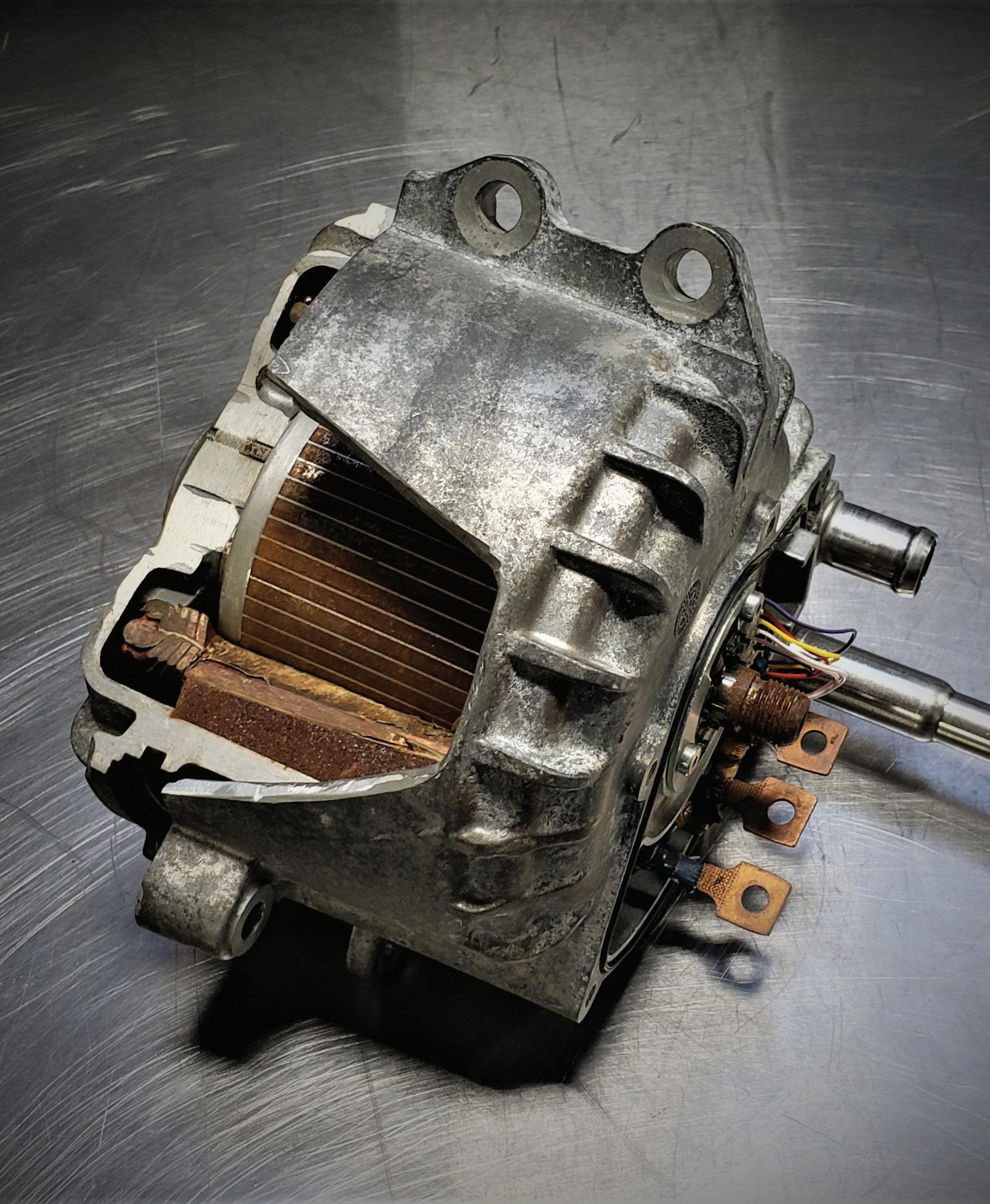
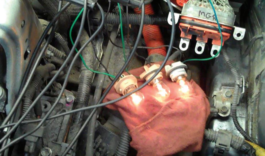


VISION’s final night on Saturday is ending on a whole new level of excitement. The ultimate send-off: highenergy racing, games, and celebration at Andretti Indoor Karting & Games!
Tickets available for purchase when registration opens. Group transportation provided.
Saturday, March 7, 2026 6:00 PM - 10:00 PM


and GM eAssist for example), the rotor has no magnets. It also rarely fails (Figure 4). The only thing that may happen is the rotor would scrape the stator if the support bearings failed. This would pro-
duce aluminum and copper dust. In turn, that will short the AC to the chassis and the system will set a fault code for a HV leak. Game over. That leaves the stator as a suspect. The stator can be damaged with
heat, by poor construction, attacked by acids in old transmission fluid (the stator is often cooled that way), magnetic vibration issues, and loose connections (more heat). The stator is not visible without a

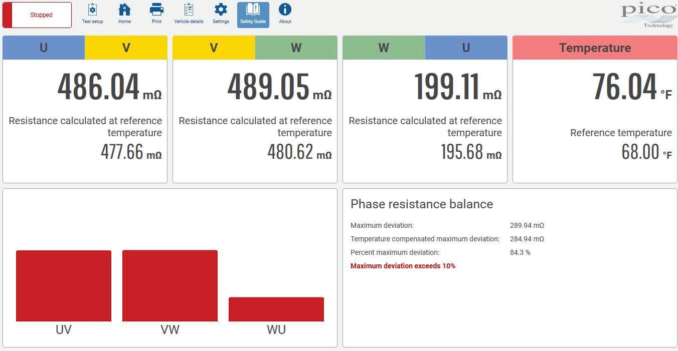
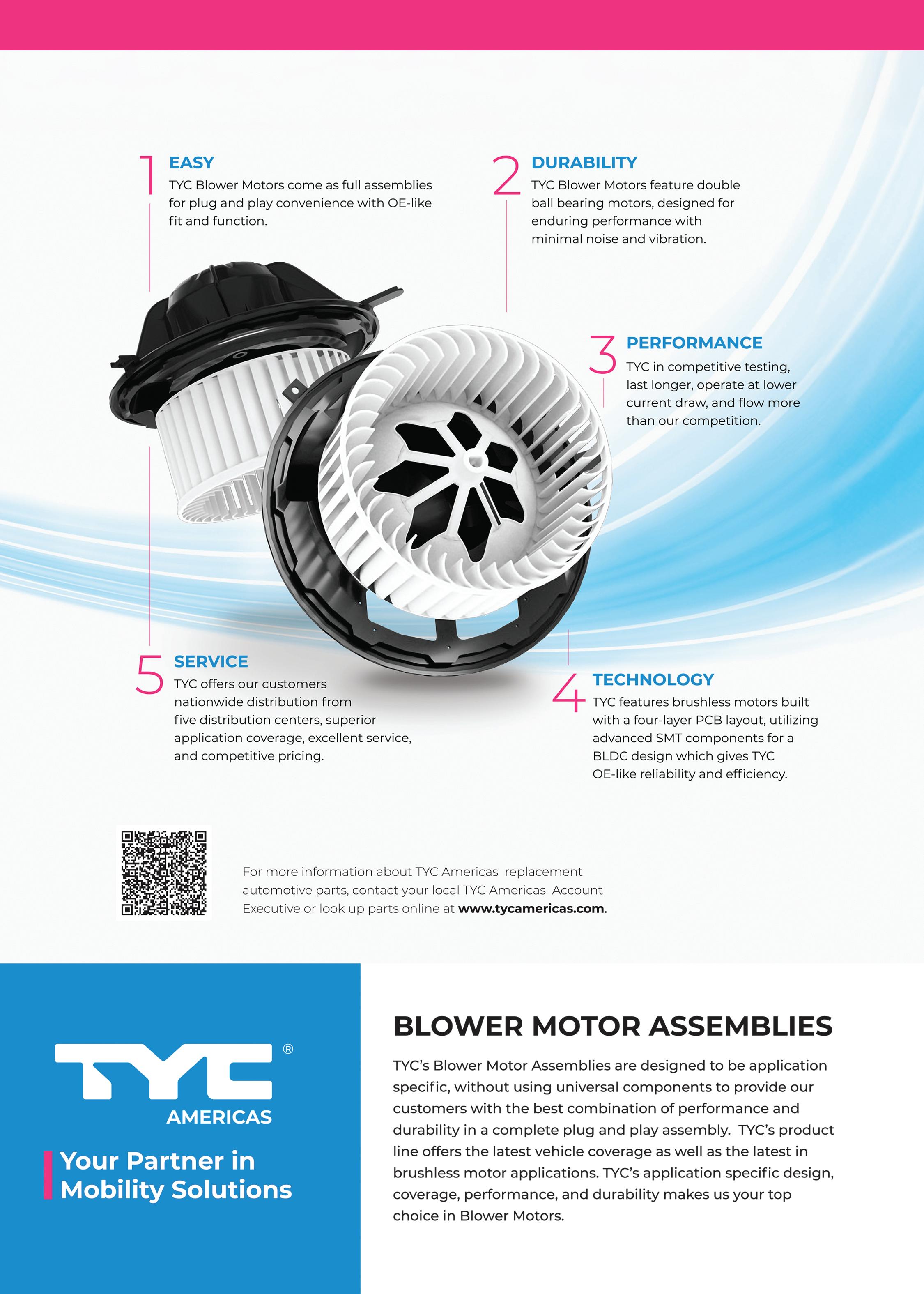

lot of disassembly in most cases, so how do we test for a problem there? If it is a PM motor and you can figure out a way to rotate the rotor, it can be easy.
Here are four tests to try:
Test 1: Make a three-bulb tester. You will need three old fashioned filament bulbs (for example No. 1587). Using the bulb socket holder, attach two alligator clips to each wire so you have three light bulbs that are the same. Once the threephase cables have been removed from the inverter, connect the bulbs to the three cables (Figure 5) and rotate the rotor. The bulbs should all light up and be the same intensity. If one is dim, verify that the connections are good by changing the positions of the bulbs. A dim bulb indicates low output on one phase.
Test 2: While the bulbs are attached to the inverter, connect a lab scope to the orange cables and watch the amplitude. The bulbs will still light up, but now you can see a wave form. The three phases should all look the same (Figure 6).
Test 3: Using a milliohm meter, make the same connections to the three-phase
cables. You may need to look up a specification if the test shows an out of balance stator phase. Once you have learned how to use your milliohm meter, make sure the three phases are all equal in ohms. This test will help us discover shorted stator windings that short to each other in the same phase, short to ground, short to the temperature sensor (if it has one) or shorts to another phase (Figure 7). If the test shows a failure, take the motor apart enough to remove the orange cables from the system and test again at the stator itself. It is possible to a have a high resistance connection or a bad orange cable and the stator may be OK.
Test 4: This test will make use of your insulation tester (like a Fluke 1587). You are now adding high voltage (with very low current) to the stator and attaching the meters ground lead to the stator’s case. You are looking for an isolation issue that will show you bad insulation on the coil windings of the stator (Figure 8).
The four tests can all be done in under 30 minutes once you know your equipment and have access to the orange
cables that feed the AC to the stator. There are only two tests for induction motors, tests 3 and 4, as there are no magnets. Once you have determined the stator is defective, it must be replaced. There are companies that can rewind a stator, but typically it is replaced with a new one. Some OEMs have designed this for easy removal and other OEMs will have you replace the entire assembly.
There is always new equipment and more to learn. A new era is here.

VAN
is the CEO of ACDC, a hybrid and plug-in training company based in Worcester, Mass. ACDC has been offering high voltage classes since 2000, when the Honda Insight came to the USA. When EVs were introduced in 2011, ACDC added them to their classes. Reach Craig via email at Craig@ fixhybrid.com or call him at (508) 826-4546. Find ACDC at www.FIXHYBRID.com.


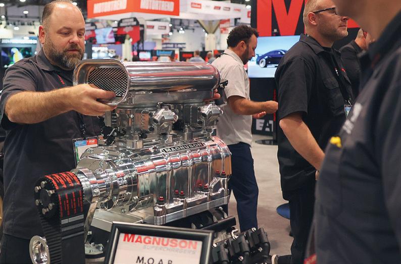


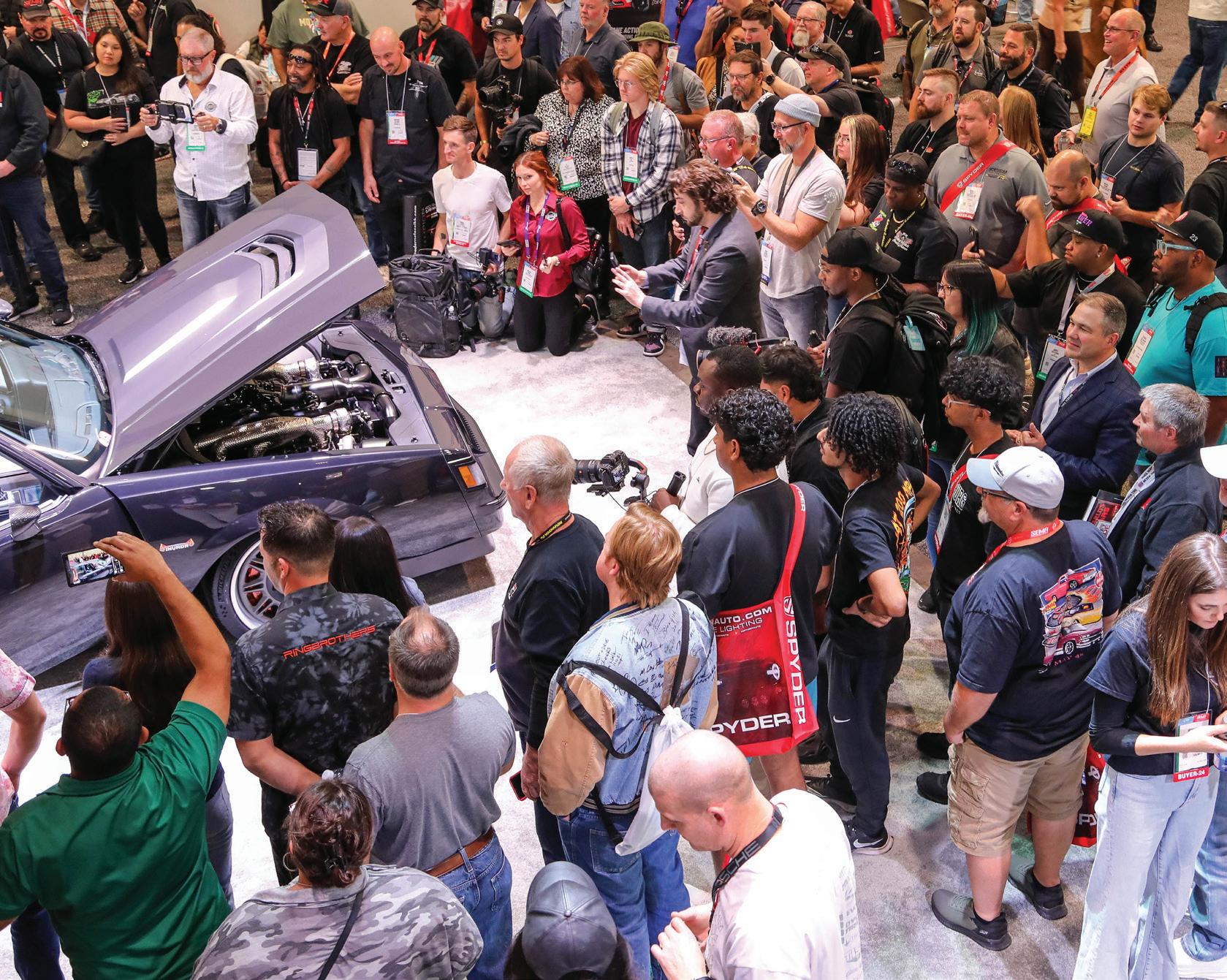


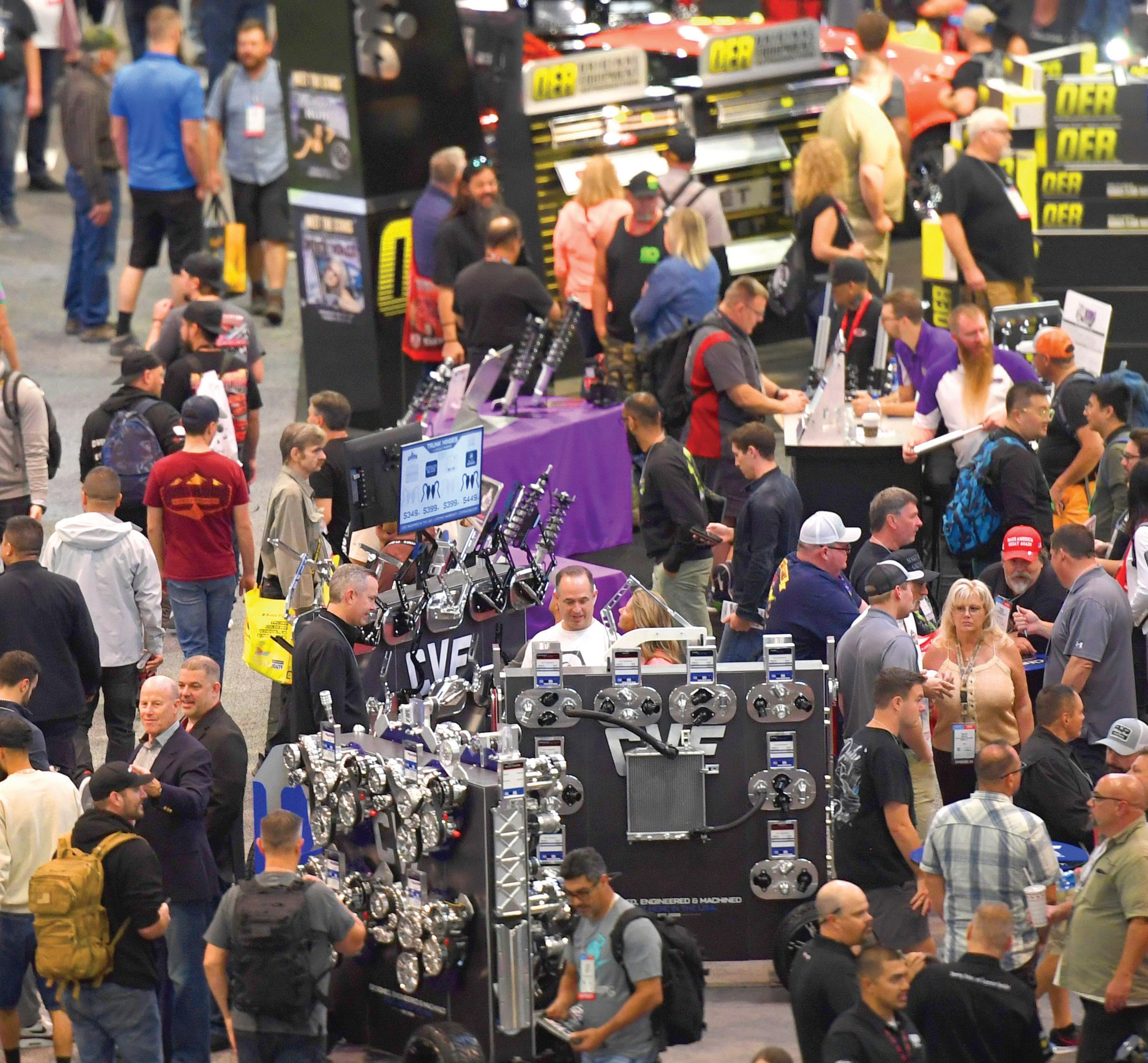


The Matco Tools 12V Cordless Infinium 1/4” Stubby Impact Wrench Kit, Nos. MCL1214BIBK, MCL1214BIGK, MCL1214BIMK, and MCL1214BIPK, feature an overall length of less than 5” and deliver 100 ftlbs of breakaway torque. Designed for versailte voltage compatibility and powered by a brushless motor, it offers maximum productivity through efficient design and extended run-time. Built smart for the user, it provides an excellent power-tosize and weight ratio. The kit includes the cordless impact wrench, two 12V 2.5Ah batteries, a charger, and a convenient carry bag. Now available in blue, green, orange, and purple.
A DY DY A DY
DY A DY DY A DY DY


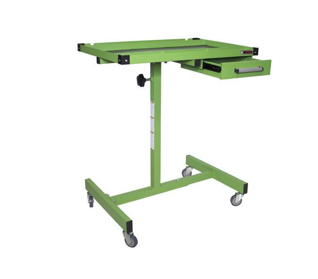
The K-Tool International 30” Adjustable Work Table offers a total capacity of 200 lbs and a worktop capacity of 178 lbs, and it features a top tray, durable drawer liners, and a 12-5/8” x 9-7/8” x 2-3/4” drawer with a holding capacity of 22 lbs. The table is made from 16-gauge steel and adjustable from 34” to 47” with an adjustable leg width from 26-5/8” to 31-5/16” for additional flexibility. It uses four 2-1/2” swivel casters for easy maneuvering and weighs only 32 lbs. The table comes with a year-long warranty.
The Snap-on TRITON features a wireless connection, a sleek, streamlined design, rugged grip handles, and a lightweight body. Fast-Track troubleshooting allows users to see how other technicians have tackled the same problems. Smart Data automatically selects the PIDs related to the code that the technician is working on and flags which ones are out of range. Pre-filtered functional tests and technical service bulletins help confirm the right path to repair. Guided component tests and a 2-channel scope help users confirm the fix. Its 10” capacitive color touchscreen display provides improved readability and superior visibility. With fast boot-up and one-touch code scan and clear, users can work more quickly through repairs.
The CTA Tools Magnetic Flex Tray, No. 5060, holds a wide range of components, including bolts, nuts, washers, spark plugs, oil filters, screwdrivers, pliers, ratchets, and more. It features three encased magnets that provide a rust-free magnetic hold and a heat- and chemical-resistant silicone body. The two-step dumbbell shape helps separate parts, and the 1” raised edge keeps tools secure. The tray has a soft-touch, non-scratch surface and measures 13” x 6” x 1.5”.
The Ko-ken Impact Wheel Nut Sockets feature a detachable plastic protector that can be fitted to the socket to prevent damage to the wheel when working in tight spaces. Each socket has its size and a Ko-ken mark clearly printed on the shaft, making it easy to see if the socket is still rotating or stopped. The sockets have a thin-walled shape and 110mm length for accessing nuts recessed deep in the wheel, and a rubber stop is located at the base of each socket to protect the lug nut from damage. The sockets are color-coded by size: blue for 17mm, red for 19mm, yellow for 21mm, and white for 22mm.

The TP58 TPMS Diagnostic Tool from TOPDON allows users to activate, read, diagnose, and service all major OEM and aftermarket sensor brands. Technicians can access sensor IDs, temperature, battery status, and more. It’s compatible with 100 percent of OEM sensor diagnostics and 90 percent OBD-II coverage. Additional features include: fast, intuitive touchscreen interface; Wi-Fi connectivity for automatic updates, OBD-II relearn and TPMS DTC reading; custom placard adjustments; ECU unlocking for Toyota and Tesla BLE support; five years of free software updates; DOT recording and tire tread depth measurement support; make, model, and year lookup via VIN barcode scan; and optional tire tread depth gauge.

This bulletin applies to 2021 Acura ILX and 2022 MDX vehicles. The MIL may be on with DTC U0155 (lost communication with gauge control module). During certain conditions after conducting an evaporative emissions leak check, a mismatch in control module shutdown commends results in the DTC being set. Update the PGM-FI software, using i-HDS software version 1.006.026 or later and HDS software 3.104.014 or later. (Photo: Acura)

Some 2023 Lincoln Corsair vehicles equipped with a 2.5L plug-in hybrid
electric vehicle (PHEV) engine built on or before Sept. 7, 2023, may exhibit an illuminated powertrain malfunction (wrench) indicator with DTC U1010 stored in the secondary on-board diagnostic module-B (SOBDMB). This concern typically happens after a plugin charging event. This may be due to software in the SOBDMB. To correct the condition, update the software with the latest available version. (Photo: Lincoln)

This bulletin applies to 2017-2023 Chrysler Pacifica vehicles built on or after Aug. 12, 2016, and on or before Dec. 27, 2022, and equipped with a 3.6L V6 hybrid engine and eFlite SL-eVT transmission. The MIL may be on, the vehicle may be in limp mode, with one or more of the following DTCs:
• P0A3F (drive motor A position sensor 1 circuit)
• P0A43 (drive motor A position
sensor circuit intermittent)
• P0A45 (drive motor B position sensor 1 circuit)
• P0C1A (drive motor B torque delivered performance)
The cause may be an internal wiring harness connector short or motor A bearing support burrs may be causing bearing failure. Repair the transmission with the electric rebuild kit P/N 68729719AB. Clear all DTCs. The HCP (hybrid control processor) and AHCP (auxiliary hybrid control processor) must be updated to the latest available software after the repair. (Photo: Lincoln)

This bulletin applies to 2020-2024 Cadillac CT4, CT5, XT5, and XT6 vehicles equipped with a 2.0L or 2.7L engine. The MIL may be on with DTC U0672 set current or in history. The cause is potential electric engine coolant pump connection.
Check for and correct any related wiring contamination, terminal tension, crimp or lock issues as needed. If no issues are isolated during inspection, cycle the electric engine coolant pump connection and clear the DTC. (Photo: GM)

Some models of 2023 Mitsubishi Outlander PHEV SE vehicles have a crimping type nut on the hubs. If the cramped area of the hub nut is not properly
released before the hub nut is removed, the threaded portion of the axle shaft can be damaged, resulting in unnecessary axle shaft replacement.
There are two types of lock nut chisels. For Outlander/Outlander Plug-in hybrid, the correct tool is P/N KV40108800. For other models, use MB992700. (Photo: Mitsubishi)

This bulletin applies to 2021-2024 Audi
The safest, most compact, and precisely designed tool available to service extra large retaining rings
Compound screw lever for easy ring installation and removal
Includes six pairs of alloyed steel color-coded replaceable tips and a hex wrench in a hardy tip kit pouch
A4, S4, A5 Sportback, S5, Q5, SQ5, Q7, SQ7, Q8 and SQ8 vehicles. The exhaust emissions warning lamp may be illuminated, or the warning lamp for coolant temperature/low coolant level lights up, and/or the fan runs continuously. If the fan(s) run(s) continuously, DTC P048000 (cooling fan 1 control circuit) and/or P048100 (cooling fan 2 control circuit) may be stored. In rare cases, an open circuit in the wiring may occur. As a result, the radiator fan may be identified as a component that potentially causes damage.
Switch the ignition on so that the main relay is activated. Unplug the connector to the fan and check the voltage supply on the control wire 87 while it is under load. If this is OK, switch ignition off and check the PWM wire for an open circuit between the connector from the engine control unit


and the connector from the fan. If this is OK, perform Guided Fault Finding per the service manual. (Photo: Audi)

This bulletin applies to 2021 Jaguar E-PACE and F-PACE vehicles. The customer may experience poor passenger compartment heating performance and/ or slow to warm up. EV mode may be unavailable with DTC B1DC5-64 stored in the HVAC module. The high voltage coolant heater (HVCH) may be inoperative.
This DTC is stored for one of the following reasons:
• No or low flow in the cooling system
• Air in the cooling system
• Auxiliary passenger compartment coolant pump issue
• Coolant hose incorrectly installed or faulty
Do not renew the HVCH if DTC B1DC564 is stored. This indicates that the HVCH has had an overheat prevention
event and will not operate for that drive cycle. If DTC B1DC5-03 is also stored and cannot be erased, then the HVCH should be renewed. (Photo: Jaguar)
This bulletin applies to 2019-2023 Chevy Camaro vehicles equipped with a 3.6L or 2.0L turbo engine. A squeaky noise may be heard from the front passenger side when driving over bumps. The noise may be more evident once the vehicle has reached normal operating temperature. The cause may be that the radiator air baffle on the right side is rubbing on the core support. The fix involves trimming material from the vertical and horizontal surfaces.
• Remove the right side radiator air side baffle.
• Measure 12.7mm (0.050”) inboard on the horizontal and vertical edges. Draw lines with a marker.
• Using scissors, cut along the marked lines.
Reinstall the baffle, ensuring proper clearance between the baffle and core support. (Photo: Chevy)

Some 2022 Ford Maverick vehicles equipped with a 2.5L full hybrid elec tric vehicle (FHEV) powertrain may exhibit a condition where the brakes grab during light braking at or below 6 mph. This may be due to the ABS software. Reprogram the PCM with the latest software level of the Ford diagnosis and repair system (FDRS). Also update as required the ABS mod ule, BECM (battery energy control module) and SOBDM-C (secondary on-board diagnostic control module C). (Photo: Ford)


Sponsored by:
BY BRANDON STECKLER // Technical Editor
TECHNICAL EDITOR BRANDON STECKLER is back with part 6 of his new mini-series for The Trainer. This time, it’s all about magneto resistive element (MRE) sensors.
Brandon covers the benefits automotive manufacturers gained implementing the MRE sensor in system design and construction. This sensor is what makes systems dependent upon knowing speed and direction possible to exist safely on the automobile.
But, simply configuring systems to incorporate MREs is only half of the equation. Technicians need to know how the MREs function when it comes to troubleshooting a system encounter-
ing issues. And, because most manufacturers use these MREs to determine rotational speed and direction, techs are likely to encounter faulted systems sooner than they think.
To evaluate these devices properly means having a capable tool to do so (and that would be a digital storage oscilloscope). In our video the Pico 4425a will be used to demonstrate not only what needs to be seen, but also some unique features of the Pico scope that makes diagnosis of these modern components far more efficient. These include:
• Four proprietary, BNC+ self-identifying scope inputs
• Four-way measuring cursors
• Superior filtering capabilities
• Impressive scope sample rate
• A huge data storage buffer for large scope files
• Clever math channels to reveal hidden characteristics embedded in signals If you want to know more about the construction and operation of the magneto resistive element sensors, and how to troubleshoot them accurately and efficiently, you don’t want to miss this episode of The Trainer! Look for this episode, and the entire component series, on the Motor Age YouTube channel.
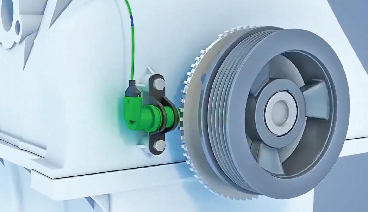

FOLLOW MOTOR AGE MAGAZINE ON YOUTUBE TO SEE NEW VIDEOS AS THEY ARE RELEASED.