


The allure of artificial intelligence continues to open new doors and inspire innovations
ARDUINO & RASPBERRY PI

PROGRAMMING LANGUAGES

PRECISE MOTION CONTROL


Pre-configured software modules for motion control
Would you rather enter parameters, or code? MOVIKIT ready-to-use automation modules are pre-configured software elements for many common motion control tasks ranging from simple speed control and positioning to complex multi-axis sequences. These intuitive, user-friendly modules are hardware independent, and can save commissioning time and costs. Simply enter paramters, and GO!


Compact pressure sensors and switches with 360° custom-color status display


www.vega.com/vegabar
Individually selectable: 256 colors
Measurement in progress
Sensor switching
Process malfunction

The allure of artificial intelligence continues to open new doors and inspire innovations
Embedded sensing in motion systems
Frequency response function and auto power spectrum can be used to measure change
Mark Holcomb, Dynamic Systems Engineering
the
travels Communication makes the machine
Biked 20 miles before you woke up this morning


You need automation technology that inspires you as much as you inspire your team. iCube Control scales and grows with your ever-expanding vision. The technology works as one, with one controller, and will perform impeccably over the life of your system, without fail and with total security. With iCube Control, you’re in total control.


CEO
President
COO
Patrick
CRO
Paul Andrews
Chief Digital Officer
Jacquie Niemiec
Chief Administrative and Legal Officer
Tracy Kane
EVP Industrial Group
Mike Christian
VP / Group Publisher
Keith Larson
editorial team
editor in chief
Mike Bacidore
mbacidore@endeavorb2b.com
managing editor
Anna Townshend atownshend@endeavorb2b.com
digital editor
Madison Ratcliff
mratcliff@endeavorb2b.com
contributing editor
Rick Rice
rcrice.us@gmail.com
contributing editor
Joey Stubbs
contributing editor
Tobey Strauch tobeylstrauch@gmail.com
contributing editor
Charles Palmer
charles101143@gmail.com
columnist Jeremy Pollard jpollard@tsuonline.com
design/production
production manager
Rita Fitzgerald rfitzgerald@endeavorb2b.com ad services manager
Jennifer George jgeorge@endeavorb2b.com art director
Derek Chamberlain
subscriptions
Local: 847-559-7598 • Toll free: 877-382-9187
email: ControlDesign@omeda.com
circulation requests / classifieds
Lori Goldberg lgoldberg@endeavorb2b.com
sales team
Account Manager
Greg Zamin gzamin@endeavorb2b.com 704/256-5433 Fax: 704/256-5434
Account Manager
Jeff Mylin jmylin@endeavorb2b.com 847/516-5879 Fax: 630/625-1124
Account Manager
Kurt Belisle kbelisle@endeavorb2b.com 815/549-1034


®


Mike Bacidore editor in chief mbacidore@endeavorb2b.com
DIGITAL TOOLS HAVE BECOME important assets for the system integrator. A variety of products and services are changing the way controls automation is utilized in equipment. At the CSIA Exchange in Dallas, the 30th anniversary of the Control System Integrators Association (CSIA) meeting and conference, Tim Ogden, director, solution provider program, GE Digital, led a panel representing the process/ discrete manufacturing industries, industrial automation and manufacturing execution and operations.
All three panelists— Brian Romano, director of technology development at Arthur G. Russell (AGR); Renato Leal, founder/CEO, GreyLogix Brasil; and Sam Hoff, president and CEO of Patti Engineering—were part of a similar panel the previous year.
At Patti Engineering, digital twins and virtual commissioning have become esteemed components in the toolkit. Patti Engineering’s use of simulation shortens the time to production start. “You have to build a model,” explained Hoff. “The whole idea is to be able to simulate the code and simulate the system beforehand. Maybe you’re building a new line for General Motors (GM); those parts are very expensive for GM to build. There are certifications on drives that are being done digitally now. It does cost a little more upfront, but you’ll save time in the field.”
“I specialize in connecting the factory floor to the business system. We were doing Industry 4.0 before it was a thing.” Romano identified four steps: expose the date; collect the data; analyze the data; apply the learning.
“My mandate when first coming onboard was to put together a data system that would differentiate us as an OEM that would do things others wouldn’t do,” explained Romano, whose vision was to build that system into the equipment, so the customer could just plug into it.
Digital twins and virtual commissioning have become esteemed components in the toolkit.
“There’s a lack of technical help out there because of the silver tsunami and COVID,” said Romano. “I put together a skills matrix. I have a spreadsheet for every employee in my department. Some are specific to us, but some are not. By being able to look at the skills matrix, I can assign the right person to the right job. Plus, I can do pairing to train new employees with skills.” GreyLogix now has an office in Florida, giving the organization three different touchpoints with customers, said Leal. “We try to make things simpler,” he noted. “We invested in an online virtual tour, so people can go into our facilities and see what we do. We created a platform where you can navigate through the system.”
Hoff explained the difference between a simulation and a digital twin. “You have to feed that real-world data back to make it a digital twin,” he said. “Now you can feed historical data back to the digital twin. In the old days of delivering a system, you handed them a manual and said, ‘Call me when it breaks.’ That’s not a good way of doing business. We have monthly calls with customers and do service calls. Through analyzing data, you can use the twin for what-if scenarios.”
Romano has been in automation more than 43 years. “We start off at the proof-of-concept level,” he explained.
When GreyLogix calls on customers, it brings a readymade opportunity for a user to enter the Industry 4.0 world. “We have a YoT box,” explained Leal. “IoT solutions are a fast-track way for customers to get to Industry 4.0. When we go to the customer, we try to remove the barriers to saying no. When the customer sees the information from his own machine or process, it’s the kind of solution you can charge as a service, so you have recurring revenue.”
Once the customer sees the information via the YoT box, Leal said he hasn’t had a customer return the contract.

Jeremy Pollard jpollard@tsuonline.com

NEW PLAYERS ARE coming into the programmable logic controller (PLC)/programmable automation controller (PAC) market all the time. Some are CoDeSys IEC-61131 based, some are C/C++ and/or Python. Raspberry Pi- and Arduinobased systems are becoming more prevalent, and their form factors are also not the norm.
I was the lucky recipient of a Portenta Machine Control PLC in a draw. It is an Arduino-based PLC used for machine control. When I first started using it, the language was foreign and unique. It took some getting used to, but I am far from an expert. The Arduino community has since released a CoDeSys IEC front end for the board.
to interface to various devices allows these brick type of solutions to be used in many applications.
Raspberry Pi- and Arduino-based systems are becoming more prevalent.
The hardware itself is a DIN rail-mounted single board with eight digital inputs and eight digital outputs and 12 programmable digital inputs/outputs. It also has an encoder input, analog I/O, RTD/thermocouple input and multiple communication ports for HMI interfacing. It also supports Ethernet and Wi-Fi, along with USB.
The product is being marketed as an IIoT and edge computing solution which can be exposed to the cloud. It certainly seems like a complete solution for monitoring and control, but not really suited for human interfacing when something goes wrong.
Inductive Automation’s Ignition Edge product can be implemented to access the database onboard the Portenta.
Raspberry Pi is another hardware platform which is becoming very popular in industrial settings. As a 64-bit quadcore processor that can run multiple operating systems including Windows, it may provide for a much different experience than an Arduino solution.
This platform is being packaged by multiple vendors as a low-cost IIoT system which has connectivity to various off-board devices and communication protocols for data and control access.
So, Arduino and Pi devices are readily available and are very inexpensive with programming solutions that can be varied yet commonplace, such as IEC 61131 languages.
The I/O looks rugged enough, and the communication possibilities are endless. Cell systems, Wi-Fi and the ability
One Raspberry Pi vendor in particular supports CoDeSys and Node-Red, along with Python with cloud-based interfaces. This can be very attractive to machine builders who use traditional PLCs for control and local interfacing, but can then add a Pi interface running data-acquisition software over MQTT to Azure for global data access for predictive maintenance data points. Legacy solutions can be modernized without touching the existing hardware or software, supporting all protocols, including OPC UA. You would be able to access any data in any system from this Pi device inexpensively.
Traditional PLC suppliers are also wandering into this arena. The main issue here is cost. An Arduino-based system may be deemed to be less expensive. Paying $69 for a CPU controller in a case and having the ability to interface with I/O looks attractive and has support.
The programming language however in the case is limited to C/C++, which may be just fine for some depending on the application.
The world of microelectronics is starting to gain a foothold in the industrial marketplace for PLCs and PACs. Enterprising engineers are packaging these units in familiar form factors which make them a bit familiar, but in fact they are not.
An industrial electrician will not have the foundation as such to interface with these devices, generally speaking. OEM machine builders may benefit from these lower-cost entry units if their systems are closed and the engineering department has the resources to implement these devices. The ability to gather data and feed to the cloud is in itself an advantage in the PLC world. HMI applications have this capability, but if you are looking for a slick inexpensive cloud IIoT controller, you may have found it.
JEREMY POLLARD, CET, has been writing about technology and software issues for many years. Pollard has been involved in control system programming and training for more than 25 years.


Rick Rice contributing editor rcrice.us@gmail.com

IN THE WORLD of food blending and packaging where I make my mark on the world, it’s easy to forget that not every control system has a programmable logic controller (PLC) as the heartbeat of the control system. PLCs were designed to control machines and processes in harsh environments where extremes in temperature and humidity would render its counterpart, the personal computer (PC) inoperable.
PCs, on the other hand, are well-suited for an office or a climate-controlled room. PLCs would tend to be programmed using pneumonic or ladder logic whereas a PC would be programmed using a textbased programming language. PCs, therefore, were ideally suited for process control where they could be isolated from the environment in which the process operates. Isolating the control system from the environment tended to be costly and require a great deal of extra effort to make it work successfully.
interface—screen—were relocated back out to the floor, right at the heart of the process.
The core benefits of an IPC, located near the process being controlled, start with using the same technology as a desktop computer. Units are full-strength industrial computers, able to withstand harsh environments.
Programs can be written in Visual Basic, C++, Python or any other programming platform.
Traditionally, a PC would sit on a table in an office or a laboratory with a monitor, keyboard and mouse plugged in to the base unit to provide the interface with the control system. Interface cards would be added to the PC to reach the field devices. These could be industrial network protocol expansion cards for the likes of DeviceNet, ControlNet, Profinet or Ethernet I/P but could also be specialty input or output cards, as well.
One of the main advantages of that PC is the powerful processor and significant onboard memory over a traditional PLC. The process control can be developed using high-level programming languages and can feature custom graphical user interfaces (GUIs) that just are not normally available at the PLC level of hardware.
A PC can directly interact with a server in a number of ways that a PLC cannot. In fact, a PC can reside on a serverbased operating system. For this reason, PCs are often used as high-end supervisory control and data acquisition (SCADA) systems.
The need to bridge the gap between PLCs and PCs led to the development of the industrial programmable controller (IPC). With the introduction of the IPC, the computer and
The base unit is fanless, meaning that the computer is in a sealed package with cooling fins on the outside to manage the internal operating temperature. Most come with either Windows 11 or Windows 10 or Linux operating systems and, as such, can run any software package available to those platforms. Many hardware suppliers offer IPCs, and they can come in a variety of configurations. Suppliers offer versions where the base computer is standalone and peripherals are plugged into it, while other versions can be panel-mounted where the PC is integrated with a touchscreen for the graphical interface and processor in a complete package.
Industrial PCs have their own commercial operating systems and, as mentioned previously, can run any software platform designed for that operating system. Programs can be written in Visual Basic, C++, Python or any other programming platform, providing great flexibility in the finished design. Many hardware suppliers provide developer libraries to aid in integrating peripheral devices into the control design.
Unlike a PLC or programmable automation controller (PAC), an IPC can run multiple software applications at the same time. The huge advantage here, for example, is running a customized main control algorithm and being able to open up instances of other software products at the same time. Imagine a part-checking solution where the operator interface is a customized graphical interface that opens a pop-up window executing the vendor-supplied software for the vision system.
IPCs are the ideal platform for running high-end SCADA packages that take advantage of huge processing power and large static memory in the IPC to provide a slick, fast interface to the process.
At its core an industrial PC is a computer. It is a motherboard with a processor, graphics card, peripheral boards and an operating system. Technology moves on in great leaps, and operating systems have to follow. When we first purchase a PC, we are usually getting the latest and greatest technology with the best operating system available today. We install software on that PC that works with that operating system.
A PLC is based on a dedicated operating system and all of the add-on components are designed back on that dedicated system. For this reason, it is not unusual to have PLCs still operating in a production environment as many as 30-40 years after they were first installed.
To take advantage of the broader design possibilities, many hardware manufacturers of products that will sit on a plant floor or in a processing facility will choose to base their projects on an industrial PC. At first, it makes sense.
Easy PID Wiring: Tool-free, convenient wiring for efficient installation. Space-saving Design: High-density multi-layer design fits confined spaces. Expandable Connections: 4 to 12 points, expandable to over 80 points.
The development environment is much more powerful, the graphics are very eye-pleasing and the base software product can be designed and tested on a PC or laptop and then transferred into the finished hardware product. Examples of these types of products are check weighers and marking equipment but can also include operator stations.
There is no argument that the advent of industrial PCs has enhanced the development of large-scale SCADA systems and opened up possibilities when it comes to control design by allowing for IT programming languages to be used in the OT world. As long as we are careful about where we choose to use this technology, the advantages far outweigh the risks.
RICK RICE is a controls engineer at Crest Foods (www.crestfoods.com), a dry-foods manufacturing and packaging company in Ashton, Illinois.

Stable Screw-type Wiring: Ensures vibration resistance and reliable power transmission. Tool-free PID Connections: Quick and easy wiring without tools, saving time.
High Current Capacity: Handles 60A to 120A, suitable for various applications. DPD

(832) 539-4703 https://www.dinkle.com/en/home

Tobey Strauch contributing editor tobeylstrauch@gmail.com
THE TERM HUMAN-MACHINE INTERFACE (HMI) is evolving as automation advances and as technology in general advances. Really, the television, iPad and other similar devices are technically HMIs. However, for industrial automation, the HMI is typically for one machine, one point of access, and functionality for that machine.
Even if you refer to remote terminal units (RTUs) for rail or water systems or gas lines in rural Colorado, the data is remote accessible over a supervisory control and data acquisition (SCADA) system. The HMI is a subcomponent of the SCADA system. A robot cell and a palletizer with HMI is not SCADA.

tion data from motors or pressure and flow from devices via Bluetooth or wireless networks.
• Natural interfaces: Emerging trends like enterprise IoT and Industry 4.0 continue to shape HMIs, moving toward more intuitive and natural interfaces.
• Robots: Robots could become human-machine interfaces in the future because some robots are better equipped to sustain hazardous environments than humans.
A robot cell and a palletizer with HMI is not SCADA.
Attach the palletizing programmable logic controller (PLC) and HMI to a network and start grabbing material data for trending, then you may be gathering data for supervisory control. This is the traditional point of view.
However, what if you put your HMI on the network, take no data from it but allow it to be emulated on a cell phone and a person may walk the floor and read inputs. Is it called SCADA? Debatable, but the point that is being conveyed is this: HMIs are changing. Our definitions may also have to change, but, for now, it’s probably best to just ride it out before being attacked by some other acronym.
With that in mind, let’s look at the evolution of an HMI.
• Mechanical era: HMIs were a panel of mechanical buttons, gauges and doodads. Liquid-level gauges had numbers and ullage with a float. There also used to be chart recorders on ovens or furnaces that required you to load paper.
• Electrification: With advancements in electrical engineering, electrified interfaces emerged. Nameplates and buttons with switches or push buttons were groovy. For instance, hand/off/auto is a popular switch for pumps.
• Electronics integration: Chips and circuit boards allowed a screen to be made with indications and numbers. These included monochrome, symbolized data screens.
• Computerization: The advent of computers led to the computerization of HMIs.
• Mobile revolution: Mobile devices and touchscreens now allow technicians to walk the plant floor and gather vibra-
The main trend currently is the onset of HMIs in the cloud or remote to the operations on a server. This is an expansion of the SCADA and the evolution of the HMI software to allow for data collection, display and control in one package. The onset of Open Platform Communications (OPC) was a turning point that allowed data to be transferred more freely on more than one type of platform. The HMI became unbound to the programmable logic controller. Sometimes, the simpler interfaces are better. They are also cheaper. This is why integration suppliers give options at different technical complexities and price points. Also, operators may have gloves, and a screen may not last. Designing in context is key. When creating an HMI from scratch, consider the following questions:
• What does the HMI need to do?
• What is important to the operation?
• What is easiest for the operator?
• How big does the HMI need to be?
• Does the HMI need to be connected to a local network or a system network?
• Does the HMI need to collect data?
• Will this HMI be part of a bigger machine system or single machine?
• Is the environment caustic to computers?
• What is the budget?
• Is the software easy or complicated?
• Is the interface maintainable by the customer?
Tobey Strauch is an independent principal industrial controls engineer.


Charles Palmer contributing editor

AS TECHNOLOGY CONTINUES TO ADVANCE, industrial manufacturers who conceptualize, design and create position sensors are presented with a wide array of new concepts, improvements and updates on existing technologies.
The use of the global positioning system (GPS), originally created by the U.S. military, has improved through not only additional satellites, but wider bandwidth and increased rate of data transfer. These systems are widely used for outdoor positioning by relying on signals from satellites to determine accurate location coordinates.
Furthermore, once position has been established, inertial measurement units (IMUs) use accelerometers and gyroscopes to measure changes in velocity and orientation, enabling the determination of position changes.
Often used for the establishment of distance, the concept of laser triangulation has been successful. In this applica tion, the simple geometry of triangles is used to determine the distance to an object. In practice it works like this: A laser beam is projected onto the target surface at an angle. The position of the laser spot on the surface is observed by a photodetector, and the displacement of the spot provides information about the distance between sensor and target.
When high accuracy of position is required, laser interferometry comes to the fore.
Laser technology has been applied to many different measurements, from tuned laser diodes (TLDs), used in industrial gas composition makeup to light detection and ranging (LiDAR), which uses laser beams to measure distances, creating detailed 3D maps of the surroundings. LiDAR is often used in autonomous vehicles and robotics. In this latter application, laser displacement sensors, also known as laser distance sensors or laser rangefinders, use a laser beam to measure the distance to a target object.
These devices function as follows: The sensor emits a laser beam toward the target, and a photodetector in the sensor measures the time it takes for the laser light to reflect off the target and return to the sensor. The distance is then calculated based on the speed of light and the time of flight.
Furthermore, when high accuracy of position is required, laser interferometry comes to the fore. This laser interferometry utilizes the interference of laser light waves to measure small displacements with high precision.
Here, a laser beam is split into two paths, with one directed to a fixed reference surface and the other to the target object. The reflected beams are then recombined. Changes in the path length due to the movement of the target result in interference patterns, and the interference fringes are counted to determine the displacement.
Some very demanding position sensing requirements have resulted in advanced systems known as laser encoder systems. Because of the high ac curacy demands, laser encoder systems use the interference pattern created by laser light to encode position information. Simply stated, a diffraction grat ing or similar optical pattern is generated on a surface, and a laser beam is directed onto it. The reflected light produces an interference pattern that can be detected and used to determine the position of the object.
The Doppler effect has been around for many years and is defined as the increase or decrease in the frequency of sound, light or other waves as the source and observer move toward or away from each other.
Enter laser Doppler effect physics: Laser Doppler velo cimetry (LDV) measures the velocity of a target surface. In operation, a laser beam is directed onto the moving surface, and the frequency shift—Doppler shift—of the reflected light is measured. The velocity of the surface can be deter mined based on this shift.
Satellite laser ranging (SLR) is a very precise, laser-based method for determining the distance between a satellite and Earth with an accuracy of a few millimeters. SLR is primarily used in geodesy. This is because the precise measurement of satellite orbits helps to determine changes in Earth’s structure and rotation. The SLR method also makes important contributions in the field of satellite navigation.
Charles Palmer is a process control specialist and lecturer at Charles Palmer Consulting (CPC). Contact him at charles101143@gmail.com.


The allure of artificial intelligence continues to open new doors and inspire innovations

ARTIFICIAL INTELLIGENCE (AI) continues to work its way into machine control and industrial applications. From generating code and enabling autonomous operation to assessing machine health and troubleshooting bad actors, AI’s presence will only stretch the imagination.
Control of industrial equipment will likely feel the biggest impact of AI. These examples illustrate the innovations we’re already accomplishing.
ANCA’s Samuel Kirkpatrick discusses technology trends affecting machine builders
by Anna Townshend, managing editor
ANCA CNC Machines, based in Melbourne, Australia, wants to enable autonomous manufacturing, full endto-end production without human interaction. The company primarily makes computerized numerical control (CNC) machines for the tool and cutter industries, and ANCA’s technical manager for systems engineering, Samuel Kirkpatrick, believes emerging technologies are influencing machine design and older tech is morphing to meet the challenge for more automation.
“We’re starting to provide automation-as-a-service for our customers, where we’re automating things like material transfer and workflow definition between all the processes for tool manufacturing, as well as providing solutions for closed-loop or autonomous feedback on the processes themselves to be able to run closed-loop process compensation,” Kirkpatrick says.
ANCA’s Integrated Manufacturing System (AIMS) provides an open ecosystem to automate all the steps in the

production of cutting tools (Figure 1). Individual modules can be configured to tailor a system for each application. It could be a simple system with a trolley for manual pallet and tool transfer with basic enterprise-resource-planning (ERP) connectivity or a fully automated system with minimal operator interaction (Figure 2).
Part of the fully autonomous production system also includes incorporating autonomous mobile robots (AMRs) to tend the CNC machines (Figure 3). AutoFetch, the AMR that transfers pallets between the setting station to the tool grinder, also automatically transfers single tools for spot-check measurements outside of the grinder. In tool manufacturing, Kirkpatrick says, getting certain geometries to the right tolerance and maintain-
ing that tolerance can be challenging. Typically, it requires operators to manually sample tools periodically. “They’ll have an operator run a measurement cycle on something like a Walter Helicheck or Zoller tool measuring machine. Those are very specialized pieces of equipment and some of the only equipment currently available that can measure some of these geometries. And then, they’ll compensate the process on the grinding machines,” Kirkpatrick says. With AIMS, after the AMRs pick up the sample tools and bring them to a measurement machine, the results are automatically fed back into the grinding process.
AMR platforms are a rapidly expanding market, Kirkpatrick says, perhaps too much. “I suspect there will be a big explosion and then the big cull, and the strong will survive.”
One of the initial issues ANCA came up against with some AMR platforms is functional safety, Kirkpatrick says. “It’s a reality of industry that a lot of emerging tech forgets, particularly if they’re coming into industrial automation from a tangent world. And functional safety is something that we take very seriously.”
ANCA does use an AMR platform from Mobile Industrial Robots (MiR) that includes a functional safety interface, but it didn’t at first. “The first MiR platform we used didn’t have one, so it’s fairly new,” Kirkpatrick says.
The MiR platform had functional safety measures initially built into the product, but there was no functionally safe way to interact with product, Kirkpatrick explains. When ANCA asked, the supplier was already working on a solution. They worked together to expose signals that were
safety rated, which ANCA could use as part of the machine implementation on top of the AMR platform.
Functional safety in an autonomous world does raise some interesting questions. If industrial manufacturing does continue on the trend toward autonomous manufacturing, will the requirements for function safety still be there? Maybe not, Kirkpatrick says. “But we’re in that transition period where you can’t really assume that there’s going to be no people around,” he adds. “So currently, it’s a non-starter to offer a product that requires there to never be people around, but I think we’re probably not too far off from that being a reality, maybe in 10 years.” It remains to be seen, he adds, whether functional safety, will go away completely or how that will morph to accommodate autonomous manufacturing.
ANCA is also experimenting with artificial-intelligence (AI) applications across the company within its machines and as part of its own internal workflows and operation. “It is certainly one of those technologies that’s so prominent and obviously will have a profound impact on industry and life as we know it. And, really, if you’re not already playing with generative AI, you’re behind,” Kirkpatrick says. ANCA is using generative AI for code efficiency and using code development enhancers. ANCA is using GitHub Copilot as an AI programming partner and copilot. “We recognize that we have to keep our ears and eyes open because we don’t really know who’s going to be offering the best functionality because it is quite new,” Kirkpatrick says. ANCA also has a special team in-house focused on AI applications.

“I can’t really get into what they’re doing, but it’s something we are obviously taking quite seriously at all levels of the business,” Kirkpatrick says. “I think it’s going to change the way that individuals within organizations work. Unfortunately, it will probably make a fair number of roles redundant potentially, going forward, but I also think it will become a big part of industry in general at all levels.” Kirkpatrick predicts soon we’ll see generative AI getting deployed on machines, used in cloud-based tools or deployed to servo drives or relatively compact devices like proximity sensors.
The standardization of communication protocols
Kirkpatrick sees open communication protocols as having a strong influence on machine design and industrial automation now and in the future. He points to the ease and flexibility of industrial protocols like message queuing telemetry transport (MQTT), IO-Link and OPC UA and the influx of web tech into industrial as shaping their own machine design. Kirkpatrick also discusses the transition he has seen in his career moving toward interoperability and the importance of data access across the system.
ANCA uses event-driven communication protocols like MQTT in the AIMS system. Kirkpatrick says event-driven communication interfaces provide a lot of benefits to industrial automation.
Before working in Australia, Kirkpatrick worked on industrial automation in the United States, where, he says, looking back more than a decade ago, it would have been great to utilize a technology like MQTT. “If you think about automation in
general, it is very event-driven. That’s what is important. This thing has occurred, and now I want to be able to communicate that out and then act on it,” he adds. In the past, programmers had to use, for example, polling, where the machine is constantly requesting information until it gets what it needs to act on. “Being able to do that in an event-driven way really helped us with AIMS,” he says.
Web tech and industrial automation
Kirkpatrick does see manufacturing and industrial automation as generally lagging, not necessarily leading, in technology adoption. However, standard industry operation, he says, is experiencing disruption from the introduction of web tech, or the various tools, programming languages and protocols for developing
websites and web applications, such as representational state transfer (REST) application programming interfaces (APIs).
“REST APIs have become very prominent and accessible,” Kirkpatrick says. “Ten years ago, if we spoke about REST APIs, most of our customers wouldn’t know what we were talking about or be interested, whereas now, when we bring that up, once we’re talking to the right people in the organization, they’re saying, ‘That’s no problem. We can interact with that very easily.’”
When Kirkpatrick did industrial automation in the United States more than 10 years ago, it was at that phase when there used to be DeviceNet and ControlNet and communications interfaces that had bespoke, or custom, hardware, as well as bespoke communications layers that you had to interact with. “Programmable logic controllers (PLCs) shielded you from a bit of that

says Kirkpatrick. “And then you had the world of Ethernet-based comms protocols, so now they’re adopting the web hardware layer, but not quite the web comms protocols to a tee, so you have things like EtherNet/IP, EtherCAT, Modbus TCP and Profinet now all using that hardware. So that basically came out of the internet, whereas now you’re actually seeing things like REST APIs appearing at the Level 3, Level 4, ERP and manufacturing execution system (MES) coordination, enterprise-level. It’s interesting seeing that starting to cross over that boundary,” Kirkpatrick says. “I think that trend will continue because there’s so much investment in web tech.”
Industrial automation is a minority player, compared to overall web tech investment, so a large swath of developers will continue to be more familiar with web tech. “That’s one of the things that I think will help us—some of those technologies emerging out of web tech into industrial automation because it’s so easy to acquire.”
Kirkpatrick also points to the trend of industry-wide standards emerging. “One that comes to mind is IO-Link, which has really changed the landscape when it comes to I/O because a bunch of companies got together and decided to work together on a standard and then adopt it,” he adds. “Where you don’t need super high performance, you don’t need
Figure 3: The fully autonomous production system includes autonomous mobile robots (AMRs). AutoFetch transfers pallets between the setting station to the tool grinder and also automatically transfers single tools for spot-check measurements outside of the grinder.
determinism; it’s sort of a no-brainer because everyone offers products that support that interface.”
ANCA used to have to purchase radio-frequency identification (RFID) readers, which came with their own processors to integrate with the antennas, often through different communication protocols. “Now you do all that with IO-Link straight from the antenna,” Kirkpatrick says. This brought down the cost of RFID technology by about 70%, compared to what it was 10 years ago.
“I see that stuff being relatively disruptive, as well, not just smaller and smaller devices having more and more sophisticated communication technology but also standards running rampant and dominating industry,” Kirkpatrick says. “A big emerging trend is industry-wide standards that are very hard to displace because they offer so many benefits in terms of interoperability.”
A few ANCA employees sit on a committee for the Universal Machine
Tool Interface (UMaTI), a community that defines OPC UA companion specifications to promote and adopt open, standardized interface for the machine-building industry and its customers. The German Machine Tool Builders’ Association (VDW) created UMaTI to realize specific mapping and transformation of parameters through standardized configuration.
Kirkpatrick says he has turned suppliers down in the past because they use some type of proprietary communication protocols. “I don’t want to assign resources to assess your product,” he explains. “I want something that’s just a standard comms technology, so that I can get someone to play with it out of the box. I don’t want to have to pull a software engineer off a project to get up to speed on your proprietary comms protocol and then write something to interact with it, just so I can see whether your product is competitive against somebody else’s.”
It drastically lowers the barrier for swapping out components. “There
might be other machine-tool or industry-centric comms standards that become almost demanded with industry saying, ‘If you don’t support this, we’re not buying your product,’ which would be a shift from where we are now,” Kirkpatrick says. “I see a lot of that disruption from system integration no longer being quite as bespoke as it used to be.”
Right now, customers aren’t saying no to an ANCA machine because it doesn’t expose some specific set of data, Kirkpatrick says. “It’s not a deal breaker yet, but I think that is something where, if you make equipment, if you make products for industrial automation, it’s going to be really important to pay attention to what data customers are demanding and what data standards are dominating in industry,” he says. “I don’t think it’s too long before people start saying no to equipment suppliers, if they can’t get them the data that they want, even if that product’s functionality is superior.”
Artificial-intelligence demonstration at Automate illustrates the potential of machine control
by Tobey Strauch, contributing editor
Data is trending in today’s industrial environment, and many companies are advertising artificial-intelligence (AI) applications to enhance or help industrial manufacturing. There is plenty of data that goes underutilized
in the U.S. industrial space. Machine learning (ML) and AI should be wellfed in our industrial space, but the problem is the cost of setting up this new technology and having the people to develop how it’s used.
This is part of the constant debate about Industry 4.0 being a continuous process, as opposed to a step in developing smart manufacturing. The Clean Energy Smart Manufacturing Innovation Institute (CESMII) is attempt-


ing to give manufacturers access to AI applications with less cost. They are also training people to have a smartmanufacturing mindset.
Chartered by the Department of Energy and with around 200 member organizations, including universities, automation suppliers, factories and plants, CESMII is enabling small and large manufacturers to find ways of improving machines and integrating old and new platforms by using machine learning and artificial intelligence. Projects include load optimization in furnaces to save fuel during thermal processing. Machine diagnostics are being utilized to train on upset conditions. Digital twins are being used to simulate real-time process control and derive solutions without wasting product.


Other application projects include hybrid modeling for energy-efficient CNC grinding, data modeling for aerospace additive manufacturing and using self-powered sensors for data acquisition. For pulp and paper, CESMII is collaborating with Auburn University to use statistical pattern analysis to use machine learning predictive control for brown stock washer lines. The motivation is to bring forward thinking to industries in the United States that have ingrained processes and find it difficult to modernize with new ideas. Collaboration between industry, academia and government


allow for funds and resources to be shared for better manufacturing.
Phoenix Contact hosted CESMII representatives at Automate 2024 in Chicago. Its booth also included a demonstration of Sorba’s industrial AI software, utilizing GraphQL and representational state transfer (ReST) application programming interface (API), integrated with PLCnext. The AI automatically can adapt software on the business network side and add new profiles as new hardware is added to the programmable logic controller (PLC). This alleviates time on the operational-technology (OT) engineering side.
This is a smart industrial application of machine learning/artificial intelligence, or advanced data acquisition. The downside is whether we would be able to populate all the profiles properly for the vast amount of OT hardware/software configurations. The idea is amazing because it would allow the controls engineer to populate the PLC at the lowest level and then not have to transfer tag by tag to an upper OT level or to the business side. However, the profiles would be vast, and the cybersecurity would be complex. Cybersecurity would have to be limited to one direction.
Regardless, this is a tangible application of ML and AI integration that could affect machine builders. Perhaps one day, a machine may be added to an industrial process and the network be smart enough to detect the PLC and tie in the connections to the supervisory control and data acquisition (SCADA) system automatically—integration by signal recognition and a software profile. Think of the protocol headers then. They would have to be huge.
This is the idea behind the smartmanufacturing mindset. If we think outside the current box, then perhaps
we are not confined to doing things the same way we did them for the past 20 years.


One axis or fifty
One axis or fifty.


Servo hydraulic or servo electric. Position, velocity, or force control. Direct connection or through EtherCAT.
Servo hydraulic or servo electric. Position, or force control Direct connection or EtherCAT
Delta RMC Motion Controllers and graphical RMCTools software make complex motion easier, smoother, and more precise.
graphical RMCTools software make motion easier, smoother, and more precise over to or
Drive over to deltamotion.com or call 1-360-254-8688.
Get your next project moving forward more quickly than you thought possible!


MIKE MCCABE product manager, factory automation systems, Pepperl+Fuchs
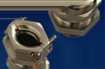
IN 1945, Walter Pepperl and Ludwig Fuchs founded a small radio workshop in Mannheim, Germany, based on the principles of inventiveness, entrepreneurial foresight and selfreliance. The experience they acquired was transformed into new ideas, and they developed products for customers. The eventual result was the invention of the proximity switch, the starting point of the company’s success story. Pepperl+Fuchs now is known for a variety of electrical explosion protection and sensor technology, including radio-frequency identification (RFID).
Q: How scalable is RFID technology for largescale industrial applications?
A: RFID technology works well for large-scale industrial applications when selecting capable equipment and partners.
Tag and reader capacity: Material-handling applications and tracking goods within a supply chain are a good example of a large-scale industrial application. Having an RFID device designed specifically for this task is necessary. Pepperl+Fuchs has recently released an UHF RFID reader for gate applications—IURF800-V1D-4A-FR2-02—which can read up to 200 tags very quickly. It covers a large area so that forklifts and even tractor-trailers can carry goods past a waypoint, ensuring that all tags are read. With the help of additional sensors, the direction can also be detected.
Large corporations have started requiring RFID tags to be attached to a majority of their assets. Pepperl+Fuchs offers an extensive line of RFID tags but can also help direct customers to tag manufacturers who specialize in large tag volumes. Pepperl+Fuchs’ specialty has always been producing reliable RFID hardware that is easy to implement.
Data volume: Large-scale operations may require increased data volumes. Some RFID devices make it easier to handle large amounts of data. For instance, the newer stand-alone industrial Ethernet UHF reader—IUT-F190-B402V1D-FR2-02—from Pepperl+Fuchs specializes in sending lots of data quickly to PLCs (EtherNet/IP and PROFINET) and the cloud (REST API and OPC UA). Pepperl+Fuchs’ IDENTControl could also be used for more complex applications. A customer may not want to choose an IO-Link-enabled RFID device due to IO-Link protocol’s inherent limitation to 32 bytes of data. If more than 32 bytes are required, multiple data packets are needed, which means more time and effort. IO-Link RFID devices are ideal for simple applications with little data.
Environmental factors: When tracking assets in a large facility or supply chain, several harsh environments may be encountered, requiring equipment that meets IP, temperature, and hazardous protection standards. While high IP ratings have always been a focus of Pepperl+Fuchs RFID products, the goal is also to operate in a wide range of temperatures. Many of the devices can modulate power in such a way to prevent overheating in hot environments. Also important is the ability to install read/write devices in hazardous environments. Fortunately, Pepperl+Fuchs has a long history of providing explosion-proof enclosures for RFID devices; whether C1 or C2, Pepperl+Fuchs has it covered.
Q: What are typical data transfer rates for RFID, and how do they affect real-time control?
A: Data transfer rates have an impact on realtime control processes. Consideration should be given to which devices are selected and how the data is used. This will ensure the continued success of RFID in high-speed manufacturing.
Frequency selection: For new RFID applications and product developments, two frequencies have come to dominate the market, and for good reason. Both high-frequency (13.56 MHz) and ultra-high frequency (860 MHz – 960 MHz) are able to handle real-time control processes due to their high data transmission rates.
Data amounts: The more data is read or written, the more time is required. While several kilobytes of data can be stored on an RFID tag, some installers prefer to store a lot of data in an auxiliary database and use the tag for identification only, linking the two together. This can be much faster than attempting to access large data sets via the tag.
Simultaneous communication: Many new RFID devices from Pepperl+Fuchs now enable the simultaneous communication to both PLCs and the cloud (MQTT, OPC UA, REST API). When real-time control of a process is required, the PLC still enables faster control. Customized SW applications via the cloud are becoming more common, but mainly for condition monitoring and status updates.
Read/write range: RFID devices create fields of energy. When tags are in these fields, their antennas can collect enough energy to allow their chips to be read or written to. The larger the field, the faster a tag can move through the field while still receiving enough energy for reading or writing. Ultra-high frequency offers much larger fields and therefore higher passing speeds, which is well suited to high-speed manufacturing environments. However, HF also has its uses. For example, Pepperl+Fuchs recently announced an extended range high-frequency RFID device— IQT3-FP-IO-V1 and IQH3-FP-V1. These new devices double the existing high-frequency read ranges, which again can contribute to faster passing speeds.
Environmental interference: Pepperl+Fuchs provides shielded cables and the ability to ground RFID devices to ensure electromagnetic interference does not corrupt data transmission.
Q: How can RFID equipment integrate with existing control systems and equipment?
A: Integration into existing control systems and installations is possible with the right devices and know-how. Challenges arise when installers face outdated protocols and tag frequencies that are no longer supported. First, to deal with an outdated protocol, a device such as Pepperl+Fuchs DeviceMasters enables the installer to

translate an old protocol into a more widely used protocol such as EtherNet/IP, PROFINET or EtherCAT.
The second issue concerns installations where outdated RFID frequencies are used. In these cases, tags with these obsolete, proprietary frequencies can no longer be purchased; thus an application cannot be easily upgraded. In such cases, the user may choose to switch everything to high frequency or ultra-high frequency. While the changeover may be a hard pill to swallow, these two frequencies are now standard and will be supported.
If the customer is looking to expand an existing high-frequency application, Pepperl+Fuchs has recently released the extendedrange high-frequency RFID device—IQT3-FP-IO-V1 and IQH3FP-V1. Converting everything to ultra-high frequency to increase range is no easy task. Since Pepperl+Fuchs has figured out how to double the high-frequency range up to about 12 inches, switching to a different frequency may not be necessary. This extended range offers additional benefits, such as the ability for the high-frequency reader to read multiple tags and selectable power settings.
There are other cases where a customer may prefer to use high frequency rather than ultra-high frequency. Ultra-high frequency radiates electromagnetic waves into the environment. These waves can bounce off metal and each other, creating areas of strong or poor readability. PowerSweep is one method to combat this problem. Radiating waves far into the environment can also cause unwanted tags to be read or written. High frequency RFID technology produces shorter read/write fields, but the field, based on inductive technology, is very coherent, and it is easier to read just one tag at a time.
For more information, visit www.pepperl-fuchs.com.
Frequency response function and auto power spectrum can be used to measure change
by Mark Holcomb, Dynamic Systems Engineering
MOTION SYSTEMS INHERENTLY have a problem that occurs over time. This unavoidable problem is “change.”
System dynamics change with temperature, with cleanliness, with wear and with fatigue. Once any one of these changes reaches a point where the existing dynamics are so different from the initial state, or expected dynamics, the system enters an unknown state of performance, and in the worst-case scenario can fail, often in a catastrophic manner.
The recovery cost of even minor, much less major failures is often measured in thousands, if not tens of thousands of dollars. The lost revenue of a down system will often be an order of magnitude worse than the recovery itself, making this alwayslurking issue a huge factor in complex motion systems.
Getting in front of motion system failures, however, is not as difficult as one may think. The solution exists in designing into the machine the right sensors, selecting the right servo drive and creating the needed code to measure and compare data on the fly. This is essentially a frequency fingerprint of the system, capturing its uniqueness and similarity to the fleet. Making machines smarter is the digital transformation that factories will rely on to remain competitive. Hardware and software are needed to execute realtime system dynamics identification, monitoring and decision-making.
Let’s discuss some of the commonly available sensors often found within motion systems, and how, or if, they can be used to monitor change.
Limit switches are a workhorse sensor in automation. These types of sensors are likely the oldest and most widely used because of their relevance. Their inherent value is their simplicity. The outcome is binary. The answer is either yes or no. At the most fundamental and simplistic level of real-time monitoring is the notion of assessing whether the system is where it is supposed to be. Limit switches can provide this information, but the yes-or-no aspect of the output limits its value, making a second level of information needed.
The servo loop and its most common position sensor, the encoder, is the next step in determining the answer to the question: Is the machine where it is supposed to be? Encoders have almost unlimited resolution capability and can be made with incredible accuracy, defining sub-micron positional knowledge. These sensors, along with Eddy current, linear variable differential transformer (LVDT) and a host of other similar positionsensing technologies, mean, if encoders or similar sensing are being used, we have everything we need, right? The short answer: No, we don’t.
Servo loop sensors are often designed around the motor, with the encoder close by, so the control of motor is
as simple and straightforward as possible. Nothing is for free in controls, and the cost of simplicity is paid for in lack of information of the load the servo is moving. The load is often mechanically away from the encoder, separated by bearings and flexible structures that move with temperature and dynamic forces. Sensors such as laser interferometers, or optical focus type sensors, do a great job of measuring the position of the load, so, in part, we are now a step closer to the real-time monitoring of what matters most to the motion system, the position of the load.
Similar to position sensors are a wide variety of servo loop sensors for metrics, such as position error, velocity error, current and current error. These are all very useful metrics and should be part of the real-time fingerprint, as they will be one of the leading indicators of when a problem does arise.
The challenge with these sensors is that they are limited in their reach. If, for instance, the position and current loop error signals have a 30% increase in their root mean square (RMS) value, the root cause is still unknown. Experienced servo engineers would likely look at stability data such as Bode plots gain margin and phase margin, but knowing where to look beyond that is pure guesswork.
If a motion system is experiencing a rise in temperature, for whatever reason, and the stiffness of the system changes in a way such that a resonant
frequency changes, maybe away from a fixed notch filter, or low pass filter, such that attenuation is reduced and gain margin becomes marginal, that resonance will now linger in its response to motion. The Bode plot may be able to capture the gain margin issue, but it won’t be able to identify the subsystem that has changed.
Servo sensors for position, velocity, current, error and the like, and loadmeasuring sensors should always be used in the real-time monitoring system, but they too lack something critical. The missing element is in subsystem knowledge. Subsystem knowl-
edge is a fingerprint of the mechanics making up the motion system. This would be components such as the x stage of a cartesian robot, or the third joint of six-degrees-of-freedom cobot, or maybe the z axis of x-y-z-Theta stage. These subsystems have their own dynamics and as such should be monitored as separate entities so troubleshooting can be very specific to where the problem resides.
The sensor that best enables subsystem testing is an inertial sensor such as an accelerometer or geophone. Accelerometers and geophones have many benefits, including their compact size, lightweight mass, simple signal conditioning
and ability to sense sub-micron and nanometer-level vibration across a wide frequency range. Designing these sensors into the fabric of the mechanics will unlock the ability to quickly identify subcomponent performance and get to root cause.
Table 1 illustrates common sensors and their pros and cons. There are many options to pick from, and each has a pro and a con. Overall, when considering all aspects, accelerometers or microphones are often the best choices for embedding motion sensors into the system.
Regarding accelerometers, they come in many shapes, sizes, performance capabilities and of course costs.
The low-cost end of the spectrum almost always means poor low frequency response and probably means they are printed circuit board (PCB) compatible. This opens a huge opportunity to undo all of the good that adding an embedded sensor can bring. A PCB accelerometer can be useful if the
right design considerations are made, namely the mounting of the chip to the PCB and the PCB to the hardware.
Any amount of compliance, lack of stiffness, means the accelerometer will be responding to its own mounting structure rather than the structure it is intended to measure.
Now that we have our embedded accelerometer identified, we need to understand which measurements will best identify how the system has changed. Two types of measurements are needed, the frequency response function (FRF) and a sub-calculation of the FRF, the auto power spectrum (APS).
The FRF is based on one signal’s relationship to another. It is simply an output compared to an input, displayed in magnitude and phase, as a function of frequency. Without going into the detailed mathematics of the fast Fourier transform (FFT), the building block of the FRF, let’s focus on two aspects: how it is constructed and how to interpret the results.

Figure 1 shows the process by which an FRF is calculated. There are two signals, the input, which is commonly force or torque, and output, in our case the accelerometer signal. The recorded signals are windowed and then processed into magnitude and phase versus frequency.
An example outcome is shown in Figure 2. The tall peaks are the system’s resonances, and these are the fingerprint of the subsystem. In the figure, let’s say the original curve was how the substructure presented when it was commissioned, and the modified line is the substructure after and while the system was experiencing an increase in temperature.
As you can see, the resonance near 780 Hz has shifted to below 700 Hz, and right away this substructure would be investigated as to why a major mechanical change was occurring.
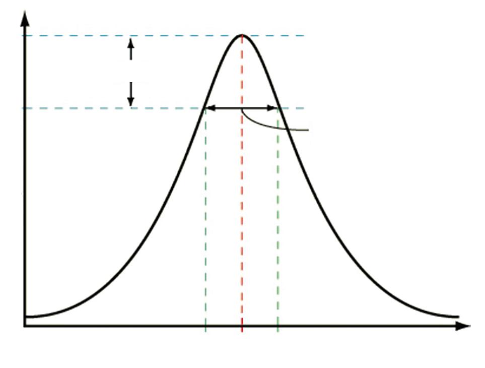
A second use case for the FRF is to monitor damping. Damping is related to the amplification factor, or Q factor. A simple and generally accepted
method for damping assessment is the formula Q=1/(2*zeta), where zeta is the damping ratio defined in the simple spring-mass-damper model of mx’’(t) + cx’(t) + kx(t) = f(t), normalized to X’’ + 2*zeta*w X’ + w2 = f(t), where c = 2*zeta*w*m and k= w2*m. This approximation is useful for widely separated resonances, where each can be treated as a single degree-of-freedom (DOF) system. A more accurate method when there are many closely spaced resonances is to use a 3 dB band calculation to get to the Q value (Figure 3). In this case, Q = f0/BW, and BW = f2 - f1.
Zeta is often stated as a percent, meaning 1% zeta is a value of 0.01. Aluminum structures will generally have 0.1-0.2% zeta damping. Figure 4 is a real-life example of a shift in structure damping at 113 Hz. Substructure FRF data can identify these types of system changes, and, with proper specification, any shift would be captured immediately, reducing the potential for exponential loss in the form of damaged parts and system troubleshooting.
One challenge with FRF data is that the system cannot be running in normal operational mode when data is being collected. The machine must be stopped while the servo drive injects force or torque into the system. The good news is that measurements should only take a few minutes each, and the system, provided everything passes, can proceed to normal operation within minutes. This diagnostic could be programmed to run once daily, weekly or monthly, all based on the risk and normal maintenance schedule.
Unlike the FRF, the APS measurement is only of one signal and does not need the system to come out of normal operational mode. In fact, these measure-


ments are most useful when collected during normal operation, to capture any change while it is occurring.
Like the FRF, the APS is an outcome of the FFT, meaning the signal is windowed first and then the FFT is calculated on the windowed data. We will not go into the specifics of the many window options, only to say the Hanning window is the best and most common option.
The basic premise of this data is to have a frequency-based signature of each major subcomponent, based on real-time movement of the system. As the system starts experiencing change of some form, the resonances of the system may change (Figure 5) in frequency, damping, or both, and the APS plot will capture this effect. Other changes could be that a band of energy, not just a single resonance may increase (Figure 6.). Figure 5 is an example of auto spectrums of passing and failing data collected with an accelerometer during tool operation.
Regarding auto power and auto spectrums, there are two options regarding how the data is displayed. The power spectrum is best used when the end goal is either to overlay signals
taken with different sample rates or to ultimately integrate the frequency data to get to an RMS value.
The power spectrum is unique, in that each magnitude on each frequency band is normalized to the frequency width. This makes data in some ways universal, which is a valuable feature. The downside is that the amplitude at each spectral line is not the actual amplitude, but, if integrated across a band, the RMS is preserved.
The auto spectrum, however, is not normalized to the frequency band but does represent the amplitude of the peak correctly. Signal-processing engineers have no shortage of strong opinions on this topic, but, in my experience, when measuring mixed signals, meaning those containing broad band noise, single tones and resonant content, it is best to use the auto spectrum with a frequency as close to 1 Hz as possible. This opinion is based mostly on the fact we most often deal with resonant or forced response peaks and rarely with the energy across a band.
A critical part of executing the APS measurement is to always collect the data under the same environmental

variables. Any change in the operation of the machine while data is being collected will change the outcome. Since the data will be collected by the servo drive, synchronizing a repeatable test during a known state of the machine should not be an issue.
Data may be desirable under multiple modes of operation, such as a constant speed or just after moving and settling. Steady-state vibration collection gives a result that is often influenced by reciprocating motion, such as a bad ball bearing within a race, a mass imbalance, a pump or oscillatory machinery onboard or somewhere within the environment or an audible tone from a wearing part. Transient vibration, by definition, is only present for a short period of time, so capturing it can be challenging. Since the servo drive will be regulating data collection, the drive can trigger data collection at the end of the move trajectory, thereby capturing a few hundred milliseconds of transient vibration data. Transient
data is best used to identify any shift in frequency or damping of structure resonances. In both cases, windowing will be needed, and, in the case of transient data collection, care must be taken to trigger the data collection appropriately to not attenuate transient vibration by the window itself. This can be accomplished through pre-triggering, thereby centering and aligning the end of the move with the center of the window.
As mentioned previously, the servo drive is the best choice for executing the FRF and auto spectrum data collection. To be successful, however, the drive must have two analog inputs and the ability to synchronously sample both channels faster than 2.5 kHz. Synchronous sampling is a requirement for the FRF, although if the lag between channels is not significant and the phase information is not used, the synchronous requirement could be relaxed. With a 2.5 kHz sample rate or higher, the usable frequency band of the FRF
and auto spectrum is 1,000 Hz, which should be sufficient for most cases.
Embedding more than two sensors is the goal of this approach, so depending on the capabilities of the drive, a secondary digitally controlled multiplexer could be implemented to route the signals to the drive in groups of two, four, six or eight, depending on the number of available analog inputs.
There are many accelerometers readily available to serve machine builders’ needs, from stand-alone, threaded mount options to PCB chip-based packages. Mass and size should be weighed against performance requirements, including shock loads, vibration range and temperature sensitivity.
Most accelerometers will need an integrated-circuit-piezoelectric (ICP) charge converter to change output to +/-10 V. The ICP circuit can be purchased as a stand-alone device, or it can be easily constructed as a daughter board to the servo drive or multiplexer.
Cabling can influence the structure by limiting its travel or by adding stiffness and damping. There are many choices when choosing accelerometers, and each comes with an assortment of cabling options. Pick the one that meets your needs. Be sure to consider length, flexibility, fatigue and shielding when making your choice.
For the FRF data, the system will need a force or torque input. Since the machine is likely to have no shortage of linear, rotary or rotary-to-linear actuators and motors, using these are the best approach.
Servo-drive manufactures likely already have the FRF and subsequent auto spectrum and windowing algorithm as part of their Bode plot capabilities. If they do not, you may want to upgrade your choice of servo drives, as the Bode utility is an excellent tool for control loop tuning and stability assessment. If they do not and you have no other choice but to use the existing drive, you will need them to embed the
calculations into their firmware or, at a minimum, record the data and upload it to a controller with the capability or export the data to a host PC. If exporting is the only option, the real-time option is now not available.
The FFT is a commonly known calculation and is part of most C, C++ and Python or equivalent coding languages. The trick is not in simply doing the FFT, but in getting the FFT into the auto spectrum and FRF correctly.
There are factors of two and square root of two, in many places within the FRF and auto spectrum calculations, so getting the math correct is essential.
One key step within FRF and auto-spectrum data collection is the notion of averaging. At a minimum, auto-spectrum and FRF data should always be averaged. Averaging reduces errors in the data and provides a statistically more accurate frequency domain representation of the time data. Many advise 30 averages, and I recommend at least 10.
The final capability needed within the software realm is the ability to generate white noise or a swept sine input. Again, this capability is within the Bode plot feature, so if the servo drive is doing Bode plots, it already can generate the signal needed. If it does not, however, white noise and swept sine code is easily found within C, C++, Python and other scripting languages.
Figure 7 shows a simplified block diagram of where the input force/ torque should be added into the motor
control. In most cases, the servo loop should remain closed, and the disturbance added into the loop, right before the axis command is split into the three motor phases. In the diagram, the white noise/swept sine is shown as an input, but this signal is internally generated within the microprocessor, and not taken in from the outside.
With hardware and software identified, the final step is creating a decision-making algorithm that deciphers failing from passing. Earlier, I mentioned the use of servo sensors such as position error, velocity error and current loop error as all part of ongoing monitoring. These metrics are always part of servo drives’ embedded fault protection, so there’s no need to discuss any strategies in how to make decisions on real-time servo data. Instead, we need to develop a method of decision making for FRF and APS data, each having at least two degrees of freedom, meaning a magnitude at a frequency repeated many times.
The fundamental aspects of the FRF are the frequency of the resonance and the amplitude. In an ideal case, each subsystem test would be searching for one resonance, but this is likely not going to be common, and each test will be looking at multiple frequencies.
First, the statistical mean of each frequency and each magnitude must be found. This is best found by testing
The fundamental aspects of the FRF are the frequency of the resonance and the amplitude.
a minimum of three, and preferably 10, systems. For each FRF, the frequencies and amplitudes of each critical resonance are recorded and stored in a lookup table within the servo drive’s random-access memory (RAM).
An error band is needed around each value, something like +/-5% on frequency and +/-10% on amplitude (Figure 8).
The trick to the algorithms will be searching out the peak and tagging the maximum value.
For the amplitude of the resonance, converting the peak using the -3 dB width mentioned previously should be considered as it gives a numerical assignment of damping versus just an amplitude value.
APS data is different than FRF data, in that we are looking for anything out of the ordinary, while also looking for what we expect to see. Accelerometer data is often converted to position, integrated two times. This creates a leftto-right downward slope to the data. The pass-fail criteria is now frequencydependent and probably different bandto-band throughout the entire range.
Figure 9 is a graphical representation of what a specification could look like, showing three requirements and across two bands. Ensuring data is above the dotted line protects against invalid data such as a non-functional accelerometer or signal conditioning circuit. Ensuring data is below the dashed line enforces the performance of the tool and protects against atypical peaks in the vibration spectrum.
Although embedding sensors to enable real-time digital fingerprinting of subsystems comes at cost, that cost is quickly recovered in one single


prevented failure or one instance of fast-tracking a root cause analysis. The value of having sensors reporting status automatically on set time intervals or at the touch of a button, saves time and resources and enhances team and machine productivity for factory or plant customers.
The ability to remotely access and diagnose machine health benefits the end user in the maintenance scheduling and uptime metrics, and it benefits the machine builder in the value and capability the band creates.
Having the foresight to embed diagnostic capabilities into complex machines involving moving parts that are subject to changes in temperature, wear and environment is an approach
that elevates machine-building. Embedded sensors not only help in maintenance and fast-tracking root cause analysis, but they also provide the builder with real-life data of how bearings, motors, gears, belts and pneumatics perform over time.
Knowing the limits of motion components such as motors, bearings, gears, belts, rollers and tensioners, for example, enables the builder to make better choices in design and in accessing the required maintenance for the end user. If the machine builder has data supporting longer service intervals versus a competitor, its factory or plant end user’s uptime will be longer, thus enhancing the machine’s value as a whole.
Industry 4.0 has been discussed for many years, and, in some manufacturing spaces, it is being fully realized. In many others, however, the technology available has yet to be fully realized for many reasons.
With advent of easily accessible and enormously powerful servo-drive capability and algorithm solutions being available across many coding platforms, there is little to no headwind in embracing the introduction of a higher level of subsystem level diagnostics.
The frequency response function and the auto spectrum have been the workhorse tools for vibration analysis for the past 40 years, since the digital FFT was implemented, and should now be a part of every servo drive in the market. Strategic placement of the right sensors within the subsystem and intelligent firmware changes that synchronize data collection with machine activity will create enormous value in predicting maintenance and increasing machine productivity.
With the right specifications and data collection methods, the real-time diagnostic/health-monitoring capability is practically limitless.

Mark Holcomb owns Dynamic Systems Engineering in Roseville, California, and has been working in the motion space for 30 years, doing structural dynamic testing/modeling and simulation, motion control, sales and product management. For documents and assistance with calculating FRF and auto spectrum, contact him at mdawsonhol@yahoo.com.
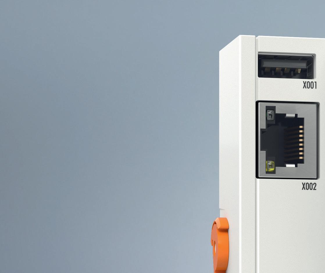
Communication makes the machine
Wago’s 750 Series I/O System offers fieldbus independence, supporting multiple fieldbus systems and Ethernet standards. A modular DIN-rail-mount design is designed to provide tool-free installation and modification.

Vibration-proof, maintenance-free Cage Clamp connections support one- to four-wire technology. International approvals (ATEX, BR-Ex, IECEx, UL508, UL ANSI/ISA, AEx, marine certifications) allow global use in harsh environments. The compact design supports up to 16 channels in a 12 mm module width. Integrated QA and 100% function testing are designed to ensure consistent quality.
Galco / www.galco.com

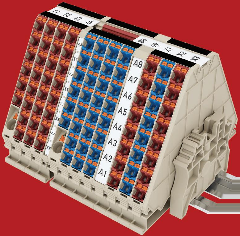
tains its conventional Push-in connection advantages so any solid conductor or ferruled stranded conductor can be inserted without using the lever. DPH series is available from conductor sizes 1.5 mm² to 16 mm², rating up to UL 600 V, 82 A and 4 AWG.
Dinkle / www.dinkle.com
Designed to gain maximum flexibility and minimize clutter, Bihl+Wiedemann’s Asi-5 digital I/O module allows up to eight digital inputs/outputs.
Bihl+Wiedemann / www.bihl-wiedemann.com


The XT 2.5 terminal blocks from Phoenix Contact feature a front Push-X connection for fast and easy wiring. The XT 2.5 portfolio includes feed-through and multi-conductor terminal blocks as well as function versions for using disconnect knives, plug-in fuses and components. With Push-X technology, solid, stranded, or ferruled conductors and cross-sections can be connected manually or automatically. Push-X technology is designed to increase the efficiency of control cabinet wiring; the factory-opened clamping space is designed to reduce installation time. Phoenix Contact / www.phoenixcontact.com
Dinkle’s DPH series terminal block is designed to provide tool-free connection for all conductors. DPH adapts a tool-free lever to allow the conductors to be installed and released by simply using the lever. DPH still main -


B&R offers the X2X+ backplane bus as an option, increasing the performance of the X20 system by a factor of four. And, because all existing X20 I/O modules are already compatible with X2X+, all it takes to build more powerful machines are bus modules. The advantages of this new bus are designed to be apparent in applications that involve many I/O modules or high data volume but where short cycle times are imperative. It is possible to set up two separate cycle times so that less time-critical data is transported more slowly and generates less network and processor load. X2X+ is designed to enable faster data transfer and up to four times faster response times. In combination with this higher bandwidth, large amounts of data can be handled, and higher sampling rates can be achieved.
B&R Automation / www.br-automation.com
Phoenix Contact’s EX I/O is designed for installation in Class I, Div. 2 environments and allows safe connection to sensors and actuators located in hazardous Zone 1 and 0 environments. These environments require extra precautions because they may contain flammable

substances such as gases, dusts and fibers. The modules limit available current to the connected sensors, reducing the possibility of combustion.
DigiKey / www.digikey.com
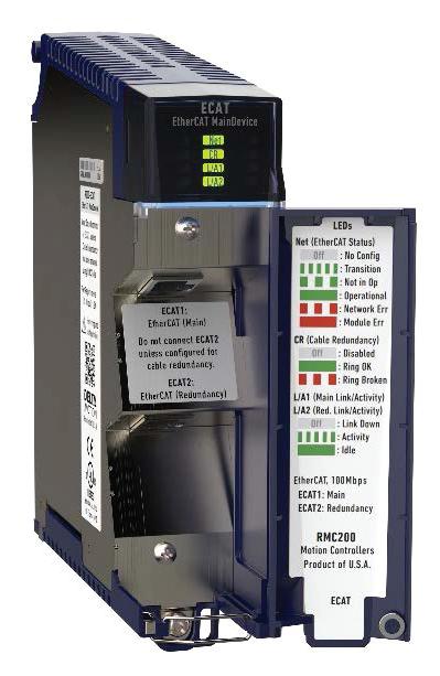
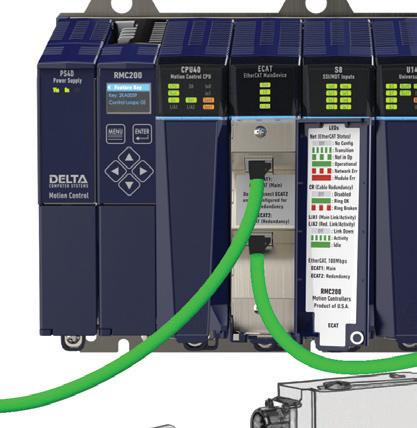
Delta Motion’s RMC200 Motion Controller family includes an EtherCAT communication module, enabling control of electric motor drives and hydraulic valves over EtherCAT. The new R200-ECAT MainDevice module is compatible with both the RMC200 Lite and Standard, allowing control of up to 18 and 50 axes, respectively. The module plugs into any RMC200 base, occupying the slot adjacent to the CPU module. Existing customers can upgrade by purchasing the R200ECAT module and performing a firmware update. EtherCAT, an Ethernetbased fieldbus system, is designed to simplify wiring, reduce costs and streamline the design of complex machines.
Delta Motion / www.deltamotion.com
The K-System from Pepperl+Fuchs is a comprehensive portfolio of isolators for any interface requirement. K-System interface modules are designed to guarantee a reliable and

economical signal transmission between your field device and the control system. The K-System is designed for quick and convenient installation due to simple mounting on a standard DIN rail. Modules are added by simply clipping them in, which, in combination with the universal power rail, is designed to eliminate the need for wiring. If modules need to be replaced or expanded, this can be done without tools or hot work permit.
Pepperl+Fuchs / www.pepperl-fuchs.com
Simatic ET 200SP is designed to adapt to your communication standard. The range of supported protocols meets all possible requirements. Despite its compact design, the Simatic ET 200SP includes integrated safety functions, and modules can be swapped during running operations thanks to the multi-hot swapping function.
Siemens / www.siemens.com


Beckhoff’s EL4374 EtherCAT Terminal is a multipurpose, combined input/output for -10/0 to +10 V or -20/0/+4 to +20 mA signals that can be used for standard automation tasks at a rate of 1 ksps per channel. The EL4374 terminal combines two analog inputs and two analog outputs in a 12-mm housing. Engineers can individually parameterize these channels for current or voltage mode using Beckhoff’s TwinCAT 3 automation software. The analog inputs and outputs are digitized with a resolution of 16 bits and transmitted to the higher-level automation device under galvanic isolation. With a signal measuring range of +107% of the nominal range, the EL4374 terminal also supports commissioning with sensor values in the limit range and evaluation in accordance with NAMUR NE43. The outputs can provide up to 107% of the nominal value. In addition, the output power allows a load of up to 750 Ω at 20 mA.
Beckhoff / www.beckhoff.com
marshalling terminal blocks

Weidmuller USA’s Klippon Connect W2C and W2T Range signal wiring and signal marshalling terminal blocks are designed to offer flexibility for complex production processes. The single- and doublelevel arrangement of these DCS marshalling terminal blocks, combined with the provision of the four basic functions—fuse, feed-through, disconnect and ground—can enable users to achieve flexibility when connecting devices wired in the field. These marshalling terminal blocks are designed to give the ability to make a last-minute change without having to change the wiring that has already been set up.
Weidmuller / www.weidmuller.com
Multicomp Pro’s IP68 range of EXE nylon cable glands are designed for intrinsic safety applications, and available in metric and PG lengths. Specifically manufactured for use in hazardous areas where there is a risk of explosion, they are suitable for environments with flammable gases, vapors or dust; come in black or grey options; include lock nut, O-ring and sealing nut; and have a working temperature range from -20 °C to 80 °C.
Newark / www.newark.com

The PSSuniversal 2 remote I/O system is the latest generation of universal I/O systems from Pilz Automation Safety, designed to offer flexibility and openness in a single system. The three-part system structure is designed for optimized handling during com-

missioning and service. Troubleshooting can be improved with LED diagnostics pinpointing a faulty module slot. Compatible with most communication modules including EtherNet/IP, Profinet/Profisafe and CIP Safety interfaces, the PSSu2 is designed to be compact.
Pilz USA / www.pilz.com
KEB offers a complete system that is compliant with safety standards IEC 61508 SIL 3 and DIN EN ISO 13849-1 Ple. The system includes the C6 Safety PLC, Safety I/O modules and programming software. These modules have a double-channel design and can be programmed through COMBIVIS studio 6, which streamlines the development and approval processes. The Safety PLC is a Fail Safe over EtherCAT (FSoE) master that works in conjunction with the machine PLC to execute and monitor safety functions. The Safety PLC can connect with other FSoE slave modules like Safety I/O and servo drives that have Safe Motion functionality. Each FSoE slave device has four safe inputs, two safe outputs and four OSSD outputs. A single FSoE master can control up to 65,535 slave devices.
KEB America / www.kebamerica.com


The NXR Remote IO series is designed to enhance organizational efficiency by streamlining inventory management and setup processes. It supports IIoT integration through its flexible configuration that combines IO-Link and digital I/O under one part number. Available in two network models, EtherNetIP and EtherCAT, it caters to different needs; EtherNetIP is ideal for data-heavy applications and easy third-party controller integration, while EtherCAT features a unique PC-less maintenance and setup for quicker field replacements. This series is designed to simplify and accelerate deployment in industrial settings.
Omron Automation Americas / automation.omron.com
A CONTROL DESIGN reader writes: We generally use ball screws for our motion applications because the conveyance systems we build require precision and speed. What other options are available for reducing backlash? Is there a formula for determining backlash based on load capacity?
When you need to achieve high precision and speed simultaneously, a ball screw drive mechanism isn’t necessarily the best option. Reversing the direction of motion induces backlash, which shows up on a metrology plot as lost motion. In other words, as the ball screw’s direction of rotation is changed from clockwise to counterclockwise, or vice versa, there is a finite amount of “slop” in the mechanism that can depend on factors, such as the ball screw’s accuracy grade, preload and lubrication. This lost motion results in a reversal error that negatively affects accuracy and repeatability.
Here are four techniques to reduce or eliminate backlashrelated errors.
The most effective solution to eliminating backlash is to eliminate the ball screw entirely and instead opt for a direct-drive solution. Linear motors, for instance, are noncontact drive mechanisms that are capable of extremely high force output, combined with high speeds and smooth motion. For the ultimate smoothness of motion, free from cogging effects and velocity ripple, ironless linear motors are the way to go (Figure 1). However, linear motors aren’t ideal for every application; for instance, linear motors may struggle to perform in vertical orientations in the absence of a counterbalance.
Therefore, when a ball screw drive mechanism is a must, here are a few proven methods by which to reduce backlash:
• Choose a more highly preloaded ball screw. A preload effectively applies force in such a way as to minimize the slop that causes reversal errors.
• Utilize direct feedback mechanisms in your design. For instance, a linear encoder can be used in conjunction with a ball-screw driven stage or actuator to measure the moving carriage’s position directly. The linear encoder therefore “sees” the backlash as position error and provides a signal to the control loop to correct for it.

Use a controller with backlash compensation capabilities. Backlash-induced reversal errors tend to be repeatable; therefore, they can be measured and compensated out. In essence, when a direction reversal occurs, the controller increases the commanded move distance by the amount of backlash previously measured, thereby offsetting the lost motion.
There are indeed techniques that can be used to estimate backlash in a ball screw. However, in practice, it’s simpler and more effective to use empirical methods to determine a backlash value. When you’re designing a ball screw into a system or machine, it’s best to consult the manufacturer’s documentation and leverage the supplier’s expertise in loading calculations, backlash estimation and lifetime estimates.
BRIAN FINK product manager/ Aerotech
Control-based vs. drive-based
There are multiple methods of compensating for mechanical system inaccuracies in servo drives and motion controllers.
Many lower cost computer numerical control (CNC) router, plasma and other gantry CNC systems do not offer motion control-based backlash compensation. Usually, these systems command the axes via pulse train outputs to the servo or stepper amplifiers. In this situation, drivebased lost motion compensation can be used to mitigate the impact of backlash, torsion or friction when the axis changes direction.
When cutting a circle without lost motion or backlash compensation, the start points of the quadrants may appear to have streaks or protrusions. This type of defect is caused by motor shaft motion being absorbed by the mechanical systems without load movement. The difference between motor shaft position and load position is considered to be lost motion. Drive-based lost motion compensation can be
utilized to minimize the difference between motor shaft and load position.
Most motion controllers offer some form of backlash compensation. Typically, a value equal to expected backlash is entered into the motion control parameters, and the target position of the axis is automatically offset to accommodate backlash or lost motion. While this value is static, backlash is not necessarily constant over the life of the machine. Wear will result in backlash increasing over the life of a system.
The most advanced servo drives offer users the ability to measure backlash during the life of the machine. When the backlash estimation function is used in conjunction with motion controller-based lost motion compensation, positioning accuracy is easily maintained over the life of mechanical system.

Upgrading servo motor couplings/electric motors
Ball screws continue to be a popular choice for motion applications. However, backlash has always been a concern, even if vendors have continued to improve the offerings. Some even sell “backlash-free” options, but, in practice, no one has eliminated it entirely. And in general, the more power required, the more backlash in the system.
Why? Because it partly depends on the components, and it partly depends on the implementation. If any one piece isn’t entirely tightened down, if there’s any give in the frame, then even the best equation won’t be accurate.
We do provide a spec sheet in our documentation that shows maximum backlash. For example, if you’re using a ball screw with 6 kiloNewtons of force, you can check how much backlash may be present when the screw nut mechanism is fully extended. But solving the challenge of backlash really comes down to component selection. Two great places to start are upgrading your servo motors to options with better couplings or trading the ball screw entirely for a highspeed, high-force electric cylinder.
Many servo motors feature a keyed shaft, so the ball screw unit has a coupling that fits that. However, the necessary tolerances to ensure the coupling will fit on the shaft can lead to wear over time. As the motor rotates one way and the other, the key and keyed slot in the coupling strike each other repeatedly, and that tolerance, which was so minimal at first, grows wider and wider. This introduces greater backlash into the system.
With keyless coupling units, you can attach the ball screw by clamping it to the shaft. That reduces backlash from the outset. More importantly, it removes the risk of backlash multiplying in production. Moving away from keyed coupling is a solid place to start, especially if you don’t have the flexibility to redesign the mechanical system in your current machine.
If you do have just a little bit of leeway, there’s an even better option for these types of applications. Substituting ball screws for electric cylinders offers an extremely highperformance and energy-saving option with no backlash. This servo-electric actuation is an ideal replacement for applications where ball screws don’t offer enough speed, accuracy or force. They’re also ideal when updating pneumatic or hydraulic systems, which are often unnecessarily large, messy and expensive due to energy consumption.
An electric cylinder experiences essentially zero backlash in the system as it retracts to position zero, even at its high-

est rating. Let’s stick with 6 kiloNewtons in this example. The unit isn’t exposed to any distortions, bending or vibrations. When the cylinder is forced into the fully retracted position, any potential backlash is transformed into thermal expansion, and the unit doesn’t generate enough heat to affect the steel actuator or impact repeatability.
That same electric cylinder, when fully extended at 6 kiloNewtons, can minimize backlash via a guide rail that helps absorb some of that load in the system. Units with anti-twist protection can limit backlash to +/- 0.02 mm at full extension.
MATT PRELLWITZ
To reduce backlash, you can adjust the ball size to lower the clearance between the nut and the screw. For applications requiring no backlash, the bearing balls can be selected to provide preload—light interference—in assembly. The most sophisticated method of providing preload is to build the internal geometry of the ball nut with an axial pitch offset, ensuring backlash-free assembly and a compact design.
Another strategy is to use a pair of ball nuts with a spring element between them. This biases the contact area between the two nuts in opposing directions against the ball screw, thereby eliminating free play within the assembly.
The load capacity of a ball screw assembly is determined by the following factors: hardness of the nut, screw and balls, the pitch line, the number of loaded ball circuits, conformity of the screw and nut forms, as well as material quality.
The backlash of the ball screw assembly does not influence the load-carrying capacity, if reasonable geometry is maintained.
ALEX MARGOLIN senior manager, design engineering / Regal Rexnord
Joey Stubbs joey.stubbs@gmail.com
IN FACTORY AUTOMATION SYSTEMS, there are a variety of different motor technologies used for different applications, depending on the demands required of the motor, system costs or interaction with other motion system components, such as coordinated motion. The types of motors typically encountered in the factory include synchronous or induction ac (alternating current) motors, DC (direct current) motors, both brushed and brushless, and permanent magnet motors. The stepper motor has been around for over a century, but has been gaining increased attention, new advancements and increased application in the last 10 years or so.
Stepper motors are crucial components in modern manufacturing and automation industries, offering precise control and reliability in a wide array of applications. Understanding how these motors function, their diverse uses and recent technological advancements provides insight into their pivotal role in manufacturing technology.

effective alternative. However, excessive acceleration and fast load cycles can result in the stepper motor no longer being able to follow the rotary field and “lose steps.” The encoder option can improve matters in this situation.
Advancements have enhanced stepper-motor technology, broadening their capabilities and applications.
• Integration with digital control systems: The integration of stepper motors with advanced digital control systems, such as microcontrollers and field-programmable gate arrays (FPGAs), has improved their precision and reliability.
Advancements have enhanced stepper-motor technology, broadening their capabilities.
Stepper motors are synchronous motors with a high number of poles. At their core, they convert electrical pulses into precise mechanical movements. Unlike traditional electric motors that spin continuously when voltage is applied, stepper motors move in discrete steps. This characteristic makes them ideal for applications requiring precise positioning, such as robotics, 3D printers, computer numerical control (CNC) machines and automated assembly lines.
Control of stepper motors is achieved through a driver circuit that sequences the energization of the coils based on input pulses from a controller, often a microcontroller or programmable logic controller (PLC). The number of steps per revolution (step angle) and the torque output depend on the motor’s construction and the drive electronics’ capabilities.
The advantages of stepper motors include high holding torque and very good positioning ability. By intelligently controlling the stator windings in full or micro-step mode, individual steps or partial steps can be driven to without position feedback (open-loop control). This distinguishes stepper motors from servo motors and makes them a cost-
• High-torque designs: Advances in magnet and rotor design have led to stepper motors capable of delivering higher torque outputs in smaller form factors.
• Closed-loop control: Traditionally, stepper motors operated in open-loop systems, relying solely on step commands without feedback on actual position. Recently, closed-loop control systems have become more prevalent, incorporating position feedback, usually through internal or external encoders, to correct for missed steps or external disturbances.
• Energy efficiency: Efforts to improve energy efficiency have led to the development of stepper motors that operate at lower power consumption while maintaining high performance.
• Customization and modularity: Manufacturers now offer stepper motors with greater customization options, allowing engineers to select motors tailored to specific torque, speed and size requirements.
• Advanced materials and manufacturing techniques: Innovations in materials science and manufacturing processes have enabled the production of stepper motors with enhanced durability, heat dissipation capabilities and resistance to environmental factors such as moisture and dust.
Joey Stubbs is a former Navy nuclear technician, holds a BSEE from the University of South Carolina, was a development engineer in the fiber optics industry and is the former head of the EtherCAT Technology group in North America.


