Electronic power steering assist systems have been around for a while, but without system knowledge, techs still get ‘turned around.’
Brandon Steckler
18 Noise, Vibration, and Harshness
Detecting and understanding NVH issues
Mike Mavrigian
24 Encoders and Smart Motors
Both play a role in today’s automotive technology
Jeff Taylor
33 It’s a Tight Squeeze
I find it more prevalent today than ever before that single-cylinder engine mechanical misfires don’t always mean a loss of compression.
Brandon Steckler
36 Regenerative Brakes
It takes two systems to slow down
Craig Van Batenburg
50 The Trainer #155 Scope Sample Rate
Brandon Steckler
Endeavor Business Media, LLC does not assume and hereby disclaims any liability to any person or company for any loss or damage caused by errors or omissions in the material herein, regardless of whether such errors result from negligence, accident, or any other cause whatsoever. The views and opinions in the articles herein are not to be taken as official expressions of the publishers, unless so stated. The publishers do not warrant either expressly or by implication, the factual accuracy of the articles herein, nor do they so warrant any views or opinions by the authors of said articles.
Endeavor Business Media provides certain customer contact data (such as customers’ names, addresses, phone numbers, and e-mail addresses) to third parties who
to promote relevant products, services, and other opportunities that may be of interest to you. If you do not want Endeavor Business Media to make your contact information
to third parties for
simply call toll-free 877382-9187 or email MotorAge@omeda.com and a customer service representative will assist you in removing your name from Endeavor Business Media’s lists. Motor Age does not verify any claims or other information appearing in any of the advertisements contained in the publication, and cannot take responsibility for any losses or other damages incurred by readers in reliance of such content. While every precaution is taken to ensure the accuracy of the ad index, its correctness cannot be guaranteed, and the publisher waives all responsibility for errors and omissions
ONLINE
EDITORIAL
GROUP EDITORIAL DIRECTOR
Chris Jones / christopherj@endeavorb2b.com
EDITOR
Mike Mavrigian / mmavrigian@endeavorb2b.com
MANAGING EDITOR
Joy Kopcha / jkopcha@endeavorb2b.com
TECHNICAL AND MULTIMEDIA CONTENT DIRECTOR
Erik Screeden / escreeden@endeavorb2b.com
TECHNICAL EDITOR
Brandon Steckler / bsteckler@endeavorb2b.com
ASSOCIATE EDITOR
Madison Gehring / mgehring@endeavorb2b.com
CONTRIBUTING WRITERS
Jeff Taylor, Craig Van Batenburg
ART AND PRODUCTION
UNDERSTANDING V2X
People like to joke about flying cars, but the idea of Vehicle-toEverything (V2X) communication works like the systems used in the sky that help aircraft to safely navigate more than 29 million squares of airspace. Just like the Automatic Dependent Surveillance-Broadcast (ADS-B) allows aircraft to communicate data points like their altitude, heading and air speed to other aircraft and controllers, V2X communication extends technologies so vehicles, pedestrians and even points in road infrastructure all communicate.
Motor Age ’s Erik Screeden, our new technical and multimedia content director, breaks down the technology, and covers the risks in a story you can read exclusively on VehicleServicePros.com. Soon you’ll see and hear more from Screeden as he adds to Motor Age ’s topnotch video reporting.
REFRIGERANT ADVANCEMENTS
No matter the time of year, technicians are trying to learn more about refrigerant. Throughout 2024 stories on new refrigerant technologies have been among the most-read stories on our website, VehicleServicePros.com. And while much of the talk has been about the evolution from R-134a to R-1234yf, technicians also need to know that blends are coming to automotive HVAC systems. Blends are already common in the HVAC systems that heat and cool your home and shop, but they’re not just for stationary systems anymore.
Subscription Customer Service 877-382-9187; 847-559-7598
MotorAge@omeda.com PO Box 3257 Northbrook, IL 60065-3257
REPRINT SERVICES reprints@endeavorb2b.com
MEMBER OF:
HOT TOPIC
Our alternators are leading a revolutionary charge.
When the industry calls for a high-performing aftermarket alternator, we say, “Charge!” bproauto® alternators are tested to O.E. standards, backed by a 2-year/ unlimited-mile warranty and achieve a 100% performance rating, making them the epitome of dependability, efficiency and noise reduction. What a revolution.
Premium aftermarket alternators. Backed by a 2-year warranty.
Save Your Skin
Protective gear won’t diminish your cool stories.
VARIOUS ASPECTS OF DAILY SHOP WORK
expose our hands and arms to heat sources and laceration damage. The list includes, but is not limited to, brake work, work on or near exhaust manifolds/pipe, hot engine heads and blocks, grinding work, use of cut-off wheels, cutting hoses, grabbing plug wires to disengage spark plug boots, reaching into cramped/tight quarters for suspension work, etc. Burnt or cut hands and forearms are pretty much a given considering the challenges we face every day. All too often, we carry these boo-boos and scars as badges of honor (unlike some folks, we actually work for a living) and occasional cuts, scrapes and blisters provide evidence of our dedication.
If you’re not already taking advantage of protective gear, it’s high time to consider saving your skin by purchasing Kevlar gloves and arm sleeves. Race car pit crews faced with servicing red-hot brakes during a race have been using these safety items for decades to avoid nasty burns and cuts. Kevlar sleeves easily slip on, and they feature a thumbhole to hold them in place and prevent them from walking up and away from the wrist. They’re flexible and not bulky at all. The abrasion resistance is superb, as the material won’t easily cut through, and heat resistance is surprisingly effective.
While evidence of hand and arm damage may make for the telling of cool stories at the bar or dinner table, at the end of the day, would you rather protect your skin and bones or would you prefer to look like a stand-in for a Frankenstein movie?
Go the Extra Mile
I’m sure that every shop encounters vehicles that arrive with really trashed interiors — empty coffee cups, miscellaneous trash, loose coins, dried up French fries, etc. Some are really just plain disgusting.
Even though the customer didn’t ask for a cleanup and detail job, consider going the extra mile by cleaning the interior, vacuuming, bagging anything that’s not trash and placing the bag in the trunk. The surprised customer will likely be grateful and impressed, and word of mouth will spread.
Yes, this will take a bit more time, but the goodwill you generate will bring that customer back to your shop in the future and will urge others to do so. It’s a good way to let customers know that you value their business. Consider doing at least a cursory cleaning underhood as well — cleaning the engine cover, or even just using a spray cleaner followed by a wipe-down. In addition to performing top-notch service, this extra effort
can go a long way in promoting your shop as a location with a high degree of professionalism. Of course, when you’re slammed with work, you may not have the time to do this, but if time permits, consider this as a boost to the business.
MIKE MAVRIGIAN MOTOR AGE // EDITOR mmavrigian@endeavorb2b.com
Don’t Resurface by Hand
Whenever performing a cylinder head service where the head has been removed and you find evidence of combustion leakage due to what you perceive as a slightly warped surface, avoid the temptation to freshen the mating surfaces using a power tool and abrasive pad. You simply cannot control a hand-held power-driven abrasive tool to maintain a flat surface. Chances are you’ll end up creating more damage
which results in surface waviness. Any block or head mating surface should only be corrected by a resurfacing machine operated by a skilled machinist. Today’s engines require an OEM-specific Ra (roughness average) in order to obtain correct mating/sealing of the head gasket. “Cleaning up” the surfaces by hand may result in a surface that “looks good” to the eye, but it will not be correct.
Can I Get a Witness?
Here’s a simple tip for those who want to verify that a mounting bolt, nut, or screw has loosened. Once a fastener has been properly tightened (torqued, torque-plus-angle, etc.,) make a witness mark on the head of the fastener and continue that mark onto the surrounding area. After a road test, or when the same vehicle comes back to the shop (perhaps it’s a come-back for the same problem), you can look at the witness mark(s) to quickly see if the fastener has moved.
This is also handy to see if the fastener has been tampered with after the vehicle left your shop — only to return at some point. Not only can you see if the fastener has loosened, but if the mark is way off — either before the original mark, which presumably would indicate it’s loose — or
if it’s past the original mark, it would indicate someone has messed with it and has re-tightened — and perhaps over-tightened — in an attempt to perform DIY work.
If you get into the habit of witness marking various fasteners that may be of potential concern, this provides a quick visual. Obviously this isn’t needed for every fastener, but it can be useful for reference, for example on connecting rod bolts, head bolts, alternator mounting bolts, a few select oil pan bolts, etc. Depending on the application, a Sharpie or white or yellow paint stick will do the trick. This is something that many race engine builders and race car builders do routinely. It simply provides an easy visual, either to spot a problem or provide peace of mind.
Brake Caliper Check
If you run into a complaint of poor braking performance where the customer states that initial pedal application doesn’t feel very strong but with successive pedal off/on applications, the brakes feel better, don’t automatically assume that the hydraulic system is at fault or that new pads and rotors may be needed. Especially if the vehicle isn’t
driven that often, or if the factory or previous service location didn’t properly lube the pad slider clips, the issue could simply be that excess friction caused by dry sliders could cause the pads to stick a bit and require additional pumps to make the pads move in/out. Provided the rotors and pads show no signs of excessive wear or glazing, remove the pads, clean the pad ears and the stainless steel slider clips, and apply dedicated brake grease on the slider clips where the pad ears make contact. It’s not uncommon for rotors and pads to be replaced un-necessarily where a lack of lubrication is the actual fault.
Ford 4WD
Some 2013-2018 Ford F-150 trucks equipped with 4WD may exhibit an intermittent grinding noise while driving in 2WD mode, most commonly on acceleration. This may be due to a loss of vacuum to the integrated wheel end (IWE) actuators and/or wear of the IWE components.
1. Reprogram the TCCM with the latest calibration.
2. Inspect the IWE vacuum hoses, looking for damage/disconnection and repair as needed.
3. Replace the vacuum check valve (located near the vacuum reservoir).
4. Disconnect the vacuum line to the IWEs at the vacuum solenoid.
5. Connect a hand vacuum pump to the IWE vacuum supply line and apply 20 in-Hg of vacuum. Does the vacuum drop more than 0.5 in-Hg per minute? If so, proceed to Step 6. If not, proceed to Step 10.
6. Using a hand vacuum pump, apply 20 in-Hg of vacuum to each IWE, one at a time and monitor the gauge. If vacuum drops more than 0.5 in-Hg per minute, proceed to Step 8. If not, go to Step 7.
7. Replace the vacuum lines between the solenoid and IWEs.
8. Remove the IWE assembly from the affected wheel.
9. Inspect the wheel bearing splines for wear/damage. If the splines show excessive wear, replace the IWE assembly and wheel bearing. If splines are OK, replace the IWE assembly.
10. Rest the IWE vacuum supply lines. Disconnect the vacuum supply line at the left or right IWE and connect a vacuum gauge to the supply line. Start the engine and allow it to idle for five minutes to build vacuum. Connect the scan tool and enter TCCM datalogger. Active command the vacuum solenoid. Repeat this test on the opposite IWE vacuum supply line.
11. If the vacuum at both left and right supply lines is greater than 10 in-Hg, go to Step 12. If not, replace the vacuum lines between the solenoid and IWEs.
12. Road test for noise by performing heavy acceleration in 2WD. Engage the 4WD system to verify proper engagement/disengagement. If the grinding noise is present in 2WD but not in 4WD, go to Step 13. If the noise is gone, the repair is complete.
13. Remove the IWE assembly from the affected wheel.
14. Inspect the wheel bearing splines for excessive wear/ damage. If damage is found, replace the IWE clutch ring and wheel bearing. If damage is not found, replace the IWE clutch ring.
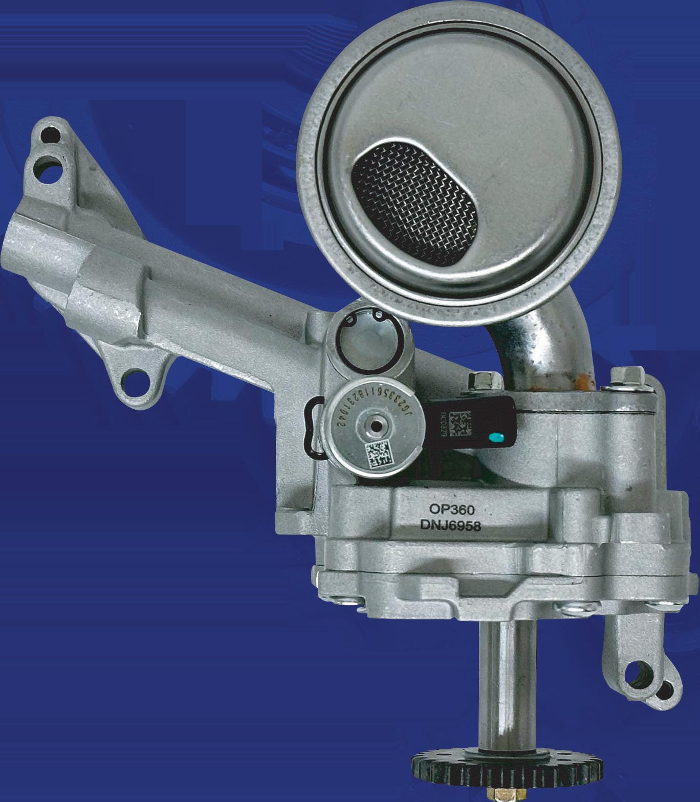
Delphi is driven to apply its OE expertise and technological leadership to engineer each fuel module with stringent standards that deliver the highest level of performance.
With over 85,000+ applications, you can install Delphi parts with confidence.
Troublesome Exhaust Leak
If you run into a minor exhaust leak (exhaust manifold to cylinder head, for example), of course the correct approach might involve replacing a slightly warped exhaust manifold, resurfacing, having trouble making an exhaust gasket seal, etc. Consider applying a thin bead of Permatex Ultra Copper RTV. This is a high temp RTV that is rated at 700 degrees Fahrenheit that actually works.
Simple Fix for Ford Truck
If you hear a whistling noise underhood while underload on a 2017-2019 Ford F-Super Duty truck, check the connection between the air cleaner lower intake duct (located under the battery tray) and the air cleaner. The connection may not be meeting properly due to a hasty filter change.
Pay Attention to Crank Flange
Be aware that some engine crankshaft flange bolt holes may be open to oil. Rather than blindly installing flywheel/ flexplate bolts, do not automatically assume that the holes are blind. Carefully inspect the crank flange bolt holes and refer to the service manual. If threaded holes are open to oil and no thread sealer is applied to the bolts, this can easily result in an oil leak that may be mis-diagnosed as a rear main seal leak. If bolt holes are open to oil, application of either a specific thread locker compound or specific thread sealant may be required. Check the service manual for specific recommendations.
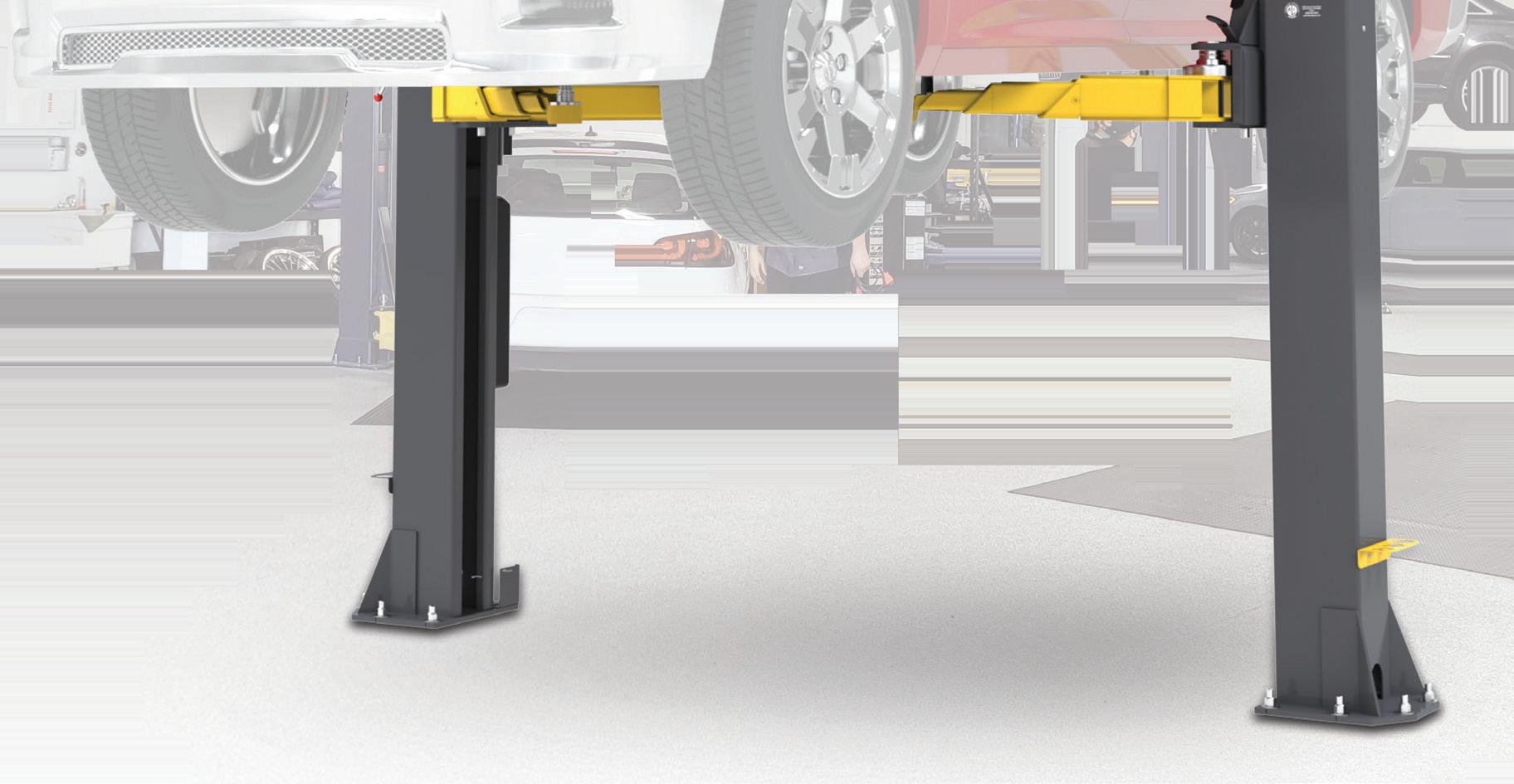
Our 10AP Series offers the convenience of wide or narrow installation wrapped up into one configurable package. This durable, safe, and reliable car lift features an expandable top beam and BI-METRIC™ arms to suit virtually every vehicle lifting requirement – symmetric or asymmetric. The 2-in-1 design gives operators the option of loading vehicles either symmetrically (centerline of vehicle at column) or asymmetrically (centerline of vehicle behind column). The simple, yet highly sophisticated design is sure to keep operating costs low and productivity high. Check out the full line of 10AP lift series at bendpak.com or call us at 1-800-253-2363.
LEARN MORE
STEERING RIGHT DIRECTION
Electronic power steering assist systems have been around for a while but without system knowledge, techs still get ‘turned around.’
BY BRANDON STECKLER
JUST LIKE ANY other system a technician will face, when a fault surfaces within an electronic power steering assist system (EPS) it’s “sink or swim.”
EPS came to be like many of the other technologies that surfaced on newer vehicles. By removing the load from the engine (created by the hydraulically assisted/power steering pump driven systems) fuel economy was improved and ultimately tailpipe emissions were notably reduced.
EPS allowed for steering assist via an electronically controlled, three-phase DC motor and electronic control unit (ECU) managing the operation of the system. The steering-column-integrated
motor provides assistance in both directions of the steering wheel and follows the input from the driver (Figure 1).
These systems perform very well, are virtually silent and eliminated the dependency on the horsepower-robbing, hydraulically-assisted power steering systems of yesterday.
System Functionality
The computer-driven EPS is just that. A system that is not smart in the slightest. It’s simply programmed to respond to inputs so it can generate the proper output. Two of the main inputs to the
ECU are the steering angle sensor and torque sensor(s) — depending on design.
The steering angle sensor is a resolver which allows for converting mechanical rotation into useful analog signals. The ECU uses these analog signals to determine the steering wheel angularity (Figure 2). The resolver signals that are output from the sensor correlate to a point within the 360-degree rotation in which the steering wheel is positioned. To clarify, this input serves as feedback to the ECU to know where the steering wheel is currently positioned. This is not only a factor in EPS strategy but also for other systems like stability control, to anticipate an oversteer or understeer condition.
Utilizing three circuits to function, the sensor has a primary winding (known as an exciter circuit) and a pair of secondary windings (known as sine and cosine). The two secondary winding circuits are offset from each other, and their associated signals vary in amplitude, sinusoidally, at any steering angle. The combination of the two secondary winding circuits’ signals provides accurate information that correlates with the actual steering angle.
The torque sensor is a dual hall-effect sensor. Its job is to report torque (steering effort/input) signals to the ECU and direction of rotation (Figure 3). There are two torque sensors so the ECU can distinguish between input from the steering wheel and input from the road wheels (which occurs when the vehicle contacts the curb, as an example). It’s the combination of these inputs that allows the EPS system to provide the right amount of assistance, in the correct direction and at the appropriate time.
Again, these are the main inputs that the ECU relies on to determine the amount of steering input effort, and the direction of that steering effort being applied to the steering wheel. The use of these signals and that of the vehicle speed will determine the amount of assistance required. The slower the vehicle is moving, the more power steering motor torque is required.
The EPS system is also used in newer advanced driver assist systems (ADAS) like intuitive parking assist. The electronically controlled EPS works in conjunction with the ultrasonic parking sensors/ADAS sub-systems. The EPS’ job in this instance is to negotiate steering wheel turning angle, vehicle trajectory and
2: THIS RESOLVER utilizes three circuits to precisely indicate steering wheel position. The exciter circuits generate electrical noise The other two (sine and cosine) circuits absorb the signal and due to the offset nature of each of them, the signal amplitude is offset as well, allowing the ECU to correlate the combined signals to steering wheel angularity.
proximity to foreign objects/other vehicles so it can place the vehicle accurately and safely alongside a curb and in between vehicles in front and behind it, for instance.
EPS System Strategy
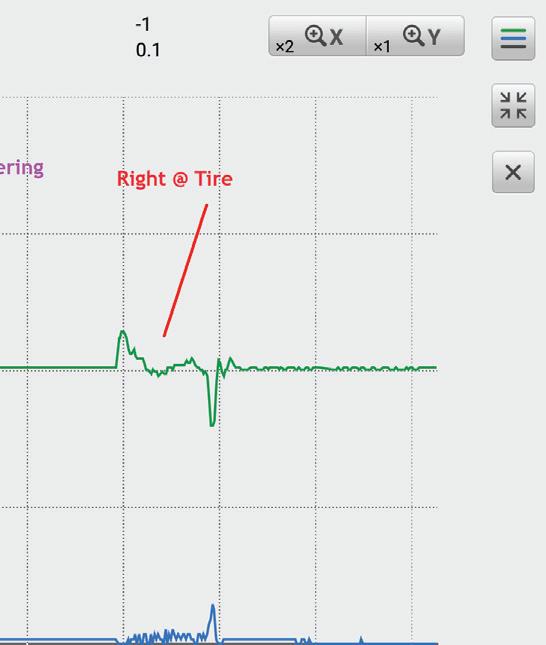
So how does this all come together? This scan tool capture of graphical EPS data tells a story. It displays action/reaction type testing to demonstrate how the EPS system strategizes to provide power steering assist (Figure 4).
FIGURE 1: THE EPS is housed entirely in the steering column assembly on this example displayed. Although this is a typical configuration, it doesn’t mean every vehicle is configured this way.
FIGURE
In GREEN is the data from the torque sensor. Again, this is the data that represents the amount of force the driver is placing on the steering wheel. In BLUE is the data from the EPS assist motor current (amperage). Otherwise stated, “the electrical work being performed.” This represents how hard the motor is working to assist the driver in turning the steering wheel.
There are three visible events occurring on the scan tool capture (left-to-right). The first event is derived from turning the steering wheel to the left. As can be seen, the GREEN trace indicates the driver provided input to the steering wheel. This is the input the ECU uses to initiate the EPS assist motor command. That command is being carried out as indicated by the BLUE amperage trace.
The second event is similar to the first. However, the steering wheel is now being turned to the right. This is indicated by an increase in amplitude from the torque sensor (GREEN trace). This time, the sensor signal is transitioning in the opposite direction, to match that of the steering wheel’s change in direction. As a result, the ECU commands the assist motor to output and provide assistance (BLUE trace).
The third event is another turn to the right. However, this event appears drastically different. During this event, the input was not at the steering wheel. Instead, I grabbed ahold of the tire and turned it to the right (input from the road wheel instead of from the driver, at the steering wheel). What is being displayed here is very minimal input from the torque sensor and as a result, very little assistance from the EPS motor (low current displayed in BLUE).
In fact, the only reason for the change in input torque being displayed is because of the steering wheel’s inertia as it is being driven by the rotating steering column. I hypothesize removal of the steering wheel from the column assembly would’ve eliminated most (if not all) of the torque signal input.
So, how does this all apply to the real world and how can it assist us diagnosticians in the work bays? Keep reading.
Testing a Lexus ES350
A good friend of mine was faced with a 2016 Lexus ES350 with a vague complaint from the driver of “Check power steering.” Like any driveability issue we face as diagnosticians, a road test (to not only duplicate the issue, but to also gather appropriate diagnostic data) should be conducted.
Equipped with a Toyota/Lexus GTS+ OE scan tool, the road test was conducted to gather data, and the fault was easily recreated. Alarmingly, the vehicle pulled to the right during a road test!
3: THE DUAL-HALL-EFFECT sensors make up the torque sensor. This device allows the ECU to see the driver’s input to the steering wheel so it can command the appropriate assist motor current output.
The vehicle was hoisted on a service lift to remove any load from the road wheels. Again, with the ignition switch in the “run” position, the steering spun to the extreme-right with no input from the driver.
It’s easy to assume that the vehicle’s power steering ECU has simply “gone bonkers” and that is where many technicians falter. But, if we take the time to address the concern and factor in the entire system (inputs versus outputs), we will ensure our ability of obtaining an accurate diagnosis.
With our knowledge and understanding of the individual components that make up EPS we can simply view the data that tells the entire story. This includes all the inputs and the outputs. Placing the data in graphical format will allow the story to be told over time.
Story Time
Since the fault was easily duplicated in the service bay, a road
FIGURE
FIGURE 4: THIS ACTION/REACTION capture from a known-good vehicle demonstrates the input (torque sensor signal) responsible for the chosen output (the assist motor current).
1. FAST & EASY PARTS ORDERING
Look up parts and place the order in seconds
2. REAL TIME PRODUCT AVAILABILITY
Find the parts you need from your store, surrounding stores, hub, or distribution center
3. LABOR GUIDE
Now
4. ORDER TRACKING
Track your order from submission to your door, where available
5. PROMOTIONS TRACKER
Enroll and track promotions for your account online
6. AND MANY MORE!
test was no longer required. In fact, a road test was quite dangerous, and the customer took a huge and unnecessary risk by not having the vehicle towed to the repair facility.
The information obtained from the scan tool capture was done right from the moment the ignition was turned to the “run” position, and the steering wheel began to turn on its own (Figure 5). So, what can be discerned from the capture?
BLUE = Wheel Speed
This represents vehicle speed and plays a factor in how much assistance to supplement the driver’s input. This indicates the vehicle is not moving and will require a lot of assistance to relieve the driver of any excessive effort.
LIGHT BROWN = Motor Current
This represents the mechanical work or effort the motor is outputting. This provides the necessary assistance (calculated by the ECU) to aid the driver in turning the steering wheel.
RED = Steering Angle Velocity
This represents how fast the steering wheel is rotated. It is reflected in “degrees per second.”
GREEN = Motor Rotation Angle
This is indicated in “degrees of rotation” and represents the change in angular position of the steering wheel.
Indicated in “voltage,” these inputs work in tandem to indicate either input from the steering wheel or input from the road wheels. Without having two different torque sensors, the ECU couldn’t distinguish between input from the road wheels or input from the steering wheel.
For instance, right-turn input from the road wheels will cause torque sensor voltages to oppose each other in one direction; right-turn input from the steering wheel will cause torque sensor voltages to oppose each other in the other direction. Together, these inputs represent the driver’s input, meaning how hard the steering wheel is being turned, and in which direction.
So, the story to be told from left-to-right is as follows:
• The GREEN amperage trace shows about -80 amps. This is because the steering wheel is being held stationary as the ignition is switched to “run.”
• The RED steering angular velocity trace is at ”zero” because of the stationary steering wheel.
• The GREEN motor rotation angle trace indicates about 20 degrees (just to the left of the 12 o’clock position).
• The PINK+BROWN torque sensor traces indicate the left-turn force on the steering wheel. This input is the reason for the motor current being applied.
Just prior to frame No. 12 (according to the y-axis of the graphs), the steering wheel is released from hand and the torque sensor inputs go awry, indicating steering wheel input torque for a hard right-hand turn.
The ECU is programmed to respond to this input by increasing EPS motor current for assistance, as indicated by the LIGHTBROWN trace. The RED trace and the BLUE trace show the angle and velocity of the steering wheel changing when the motor assistance is applied.
In the end a conclusive diagnosis can be drawn. I hope all of you realize that the torque sensors have failed and created a false input request for right-hand turn assistance. The component is non-serviceable and requires the replacement of the entire steering column assembly. After speaking with the customer, he admitted to striking a curb one cold, frozen winter morning and this vehicle exhibited the symptoms ever since.
Although the subject vehicle’s configuration required replacement of the steering column assembly, regardless of what failed (because it was all-inclusive), it doesn’t mean all vehicles will be configured the same way.
It is our job as diagnosticians to draw a diagnosis based on data acquisition and analysis. But none of that is possible without a thorough understanding of the system being analyzed, its configuration, and the functionality of the components that compise it.
The next time you are faced with a challenging symptom, step back and make sure you fully understand how it functions. Leverage the power of service information to determine how the system is configured. Refer to wiring diagrams to determine where and how to test the individual circuits. This will keep you out of trouble and force you to educate yourself.
By stepping away from the vehicle and focusing your efforts on developing a diagnostic game plan, your time will be better spent, and your accuracy (as well as efficiency) will increase many times over. And that is something you can’t hang a price tag on.
SCAN TO READ MORE ARTICLES LIKE THIS
FIGURE 5: THIS CAPTURE from a Toyota/Lexus GTS+ factory scan tool shows graphical EPS data from the suspect-vehicle. The story told indicates skewed torque sensors creating the incorrect right-turn assist from the EPS motor. This caused the steering wheel to rotate to the extreme right with the ignition in the run position.
BY MIKE MAVRIGIAN // Editor
Noise, vibration, and harshness (NVH) issues become a concern when the driver perceives this as a problem. The subject of NVH can include a host of issues, including but not limited to a vibration at a specific road speed, a vibration under engine load, a vibration during braking, engine noises that are unusual or simply annoying, a shake or vibration felt at the shifter, a whistling noise from underhood, what the driver perceives as a “too harsh/rough ride,” and more. When such issues arise, depending on the degree, they can be unpleasant to the senses — and the vehicle owner expects you to remedy the unwanted behavior.
Vibration
Noise, Vibration,
Telegraphing vibrations are caused by a component that transfers the vibration to another component. A wheel that is out of balance may transfer the vibration to the steering wheel. The steering system transfers this vibration to the steering wheel. Other examples would include worn or damaged engine or transmission mounts or an exhaust pipe that is touching the body that transfers the vibration to the passenger cabin, etc.
There are four basic categories that we can use to inspect a vibration issue.
It Might Not Be the Wheel’s Fault
A vibration that continues after the cause has been removed is “free” vibration. As an example, when a tire hits a pothole the vibration will stop after the pothole impact.
A vibration that only occurs as long as the force that initiated the vibration remains is “forced” vibration. If a driveshaft is unbalanced, the vibration only occurs while the driveshaft is rotating, just as an unbalanced wheel/tire stops vibrating when the vehicle is not moving. The “forced” vibration is the most common type of vibration that shops tend to deal with.
Another type of vibration involves “torsional” vibration, experienced when the vehicle is under hard acceleration (application of torque). This vibration is felt through the seat and floor.
When a vibration complaint enters the shop, try not to automatically assume the wheels are out of balance. We need to be aware that there are many variables that can be the actual cause.
This can include worn or loose wheel/hub bearings or improperly torqued wheel fasteners. The wheel may not be mated squarely to the hub face due to debris on the mating surfaces, or a CV shaft may have lost its rubber damper.
Other potentials include worn, damaged, or missing control arm bushings, an out-of-balance driveshaft, debris such as mud or ice built up in the wheel, tires that have been flat-spotted, worn shocks/struts, or excessive wheel runout (for example a lug-centric wheel mated to a hub-centric hub). If you’ve ruled out all of the above, consider inspecting for broken weld joints (on a unibody vehicle).
Check the Tire and Wheel
Don’t automatically assume that the wheels are properly centered onto their respective hubs. Some aftermarket wheels
and Harshness
may not properly center to the hubs (a hubcentric concern). Wheel-to-hub centering (a radial runout concern) should deviate by no more than about 0.004”. If the runout is out of spec, first mark the existing location, then rotate the wheel (wheel clock position relative to the hub). If the clearance is still out of specification, check the hub for runout to determine if the condition is in the hub or the wheel. A tolerance stack-up condition may exist, which may be corrected by re-clocking the wheel relative to the hub.
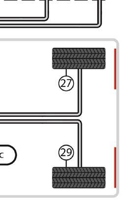
Radial Force Variation
Tire radial force variation (RFV) is a key consideration when diagnosing tire-related vibrations that occur at varying speeds and conditions. Today, vehicle manufacturers commonly phase match tires to align the tire’s point of maximum RFV with the wheel’s point of minimal radial runout (high point of tire to low point of wheel). A tire’s maximum RFV is generally indicated by a RED dot on the tire which should be aligned with the WHITE dot on the wheel (if the wheel features this dot). The red dot on the tire indicates the tire’s maximum RFV, while the white dot on the wheel indicates the wheel or rim’s minimum radial runout point. If the vehicle is fitted with alloy wheels, the tire’s red dot should be aligned with the valve stem, as this should be the minimum radial runout point. A third dot , YELLOW in color, may also be featured on the tire sidewall. This yellow dot indicates the lightest point of the tire (in terms of weight from a balance consideration).
Even if dynamic wheel balance (from a standpoint of weight) is correct, misalignment of the red and white dots will likely result in a vibration complaint.
• Red dot on tire: Align to the wheel’s low-point dimple (steel wheel), or to the valve stem on an alloy wheel, or to a white dot on the wheel if the wheel features a white dot.
• Yellow dot on tire: Align to the wheel’s valve stem.
• Both red and yellow dots on tire: The red dot takes precedence. Align the red dot to the wheel dimple or valve stem.
As any high spots on the tire contact the road surface, this results in an up/down motion. This motion transfers into the suspension system, which in turn may be felt by the driver. We’ll call this the first order vibration.
This second order vibration is caused by a second bump in the tire as a result of the change in shape due to centrifugal force.
Since there are two vibrations in one rotation of the tire, the second order vibration will be higher, about twice the frequency of the first order. A spike on a frequency analyzer will appear at that frequency.
A NVH issue doesn’t need to be the loudest noise or strongest vibration. It could be one that has recently developed or one that is simply not acceptable to the customer, while some noises may be acceptable. (This can vary among owners.)
As an example, moderate-to-loud tire pattern noise from a vehicle equipped with big block or lug pattern tires could be acceptable to the owner of a 4x4, as he or she intends to use the vehicle off-road and is willing to accept the noise when on paved
roads. However, a complaint on the same vehicle could be much more subtle, and caused by a driveline problem.
Because we sense vibration and sound using different senses, we tend to discuss them separately. However, vibration and sound are essentially identical.
A sound is a vibration, which is actually a pressure fluctuation of the air. Vibrations and sounds are both expressed as waves per second called Hertz (Hz). Vibrations between 20 Hz – 20,000 Hz are audible by humans. Vibrations over 20,000 Hz are ultrasonic and are not audible by humans.
As far as tire- and wheel-related vibrations are concerned, first perform a basic inspection. Check to see that all tires are the same brand and model, load spec and size (always check the tire tag, owner’s manual or service manual, since some vehicles may feature different front and rear tire sizes). Always check tire pressures per the tire inflation tag. Inspect each tire for damage, deformation, and wear. (Cupped treads can be an indication of worn shocks, etc.) Check for flat spots that may have resulted from brake lockup. Also, take a close look at each tire’s bead seating. An improperly installed tire whose inner or outer bead is not seated correctly will create a radial runout condition.
Brakes
Customer complaints involving vibration or noise during braking are common issues. Brake noise can either involve a squeal or a scraping noise. Squeal tends to occur when the brake pads “flutter” as they contact the rotor disc. The use of anti-squeal shims (often integrated onto many new pads) or the application of an anti-squeal silicone at the backing plates often cures this. If the caliper features multiple pistons (a two-piston caliper for instance), check the caliper for sticking piston(s) that prevent the pads from evenly contacting the rotor disc upon first application. Obviously, pads and/or rotors that are glazed should be replaced. When replacing pads, it is always recommended to either re-surface the rotors or replace the rotors, so provide a fresh contact surface so that the pad material properly transfers into the rotor disc’s machined surface.
Grinding or scraping noises obviously indicate a problem, most likely due to pad wear-out, with exposed metal contacting the rotor. Also check for foreign material that may be lodged between a pad and rotor, such as a small stone.
Braking vibrations (and associated pedal bounce) is a clear indication of a lateral runout issue, the result of either a warped rotor, which could be caused by uneven or excessive wheel fastener tightening. With the wheel removed and the rotor secured to the hub with at least three fasteners, set up a dial indicator that contacts the rotor disc surface. Preload the indicator and then adjust the needle to the zero mark. Slowly rotate the rotors while observing the dial. If lateral runout exceeds the manufacturer specs, perhaps by about 0.002” to 0.003”, the rotor should be
Frequency Ranges of Vibation and Sound
Fig. 1-3
either replaced or resurfaced with an on-car brake lathe. Before replacing or machining, place a witness mark (rotor to hub) and move the rotor to a different clock position and re-check runout, as you may have a stack-up of lateral runout tolerance between the hub and rotor. If you do find the ”sweet spot,” be sure to markit.
Wheel Bearings
A shimmy condition may be caused by worn or improperly installed wheel bearings. A front wheel bearing issue will affect front wheel alignment, making it impossible to properly set toe angle. Checking wheel bearing condition should be one of the routine checks made prior to alignment. Bear in mind that some inexpensive wheel bearings may not provide durable
EXAMPLES OF the various areas of NVH concern.
IF YOU have access to an NVH analyzer, this provides an overview of what frequencies may be perceived by the customer.
IF THE tire features only a yellow dot, this is usually aligned to the valve stem, as the yellow dot indicates the lightest point of the tire. The valve stem area (considering the weight of the valve stem and/or the TPMS assembly) is the heaviest spot of the wheel.
Steering Wheel (V)
Roof (N)
Seat (V)
Shock Absorber (N,V)
Axle Shaft (V) Tire (N,V)
Brake Drum (N,V)
Lower Arm (N)
Exhaust Muffler (N,V)
Pillar and Door (N)
Side Mirror (N)
Front Brake (N,V)
Engine Mounts (N,V) Transaxle (N,V)
Fan (N,V)
Grille (N)
Front Shock Absorber (N,V)
Engine (N,V)
Transaxle Mounts (N,V)
Drive Belts & Others (N)
CHECK BRAKE rotor lateral runout by using a dial indicator. Set up the indicator with about 0.050-inch preload, then zero the gauge. Slowly rotate the rotor while observing the dial, using a marker to indicate the point of highest runout. Perform this check several times to verify.
A RED dot on the tire indicates the tire’s high point, which should be aligned to the wheel’s low point. This may be indicated by a white dot on the wheel. Check the service manual (or the wheel maker’s instructions), as the wheel low point may be the valve stem area.
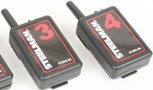
HAVING ACCESS to an NVH analyzer is very helpful when trying to isolate a vibration or noise. This unit from Steelman is but one example. Transmitters can be mounted in suspect areas, which send a signal to the receiver.
if
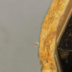
EXAMPLE OF a transmitter/transponder secured to a control arm. A wireless signal transmits results.
material/construction and may lead to lateral runout. Always select high quality bearings offered by established manufacturers.
Shaky Shift Lever
If you or the customer feels a vibration at the shifter (assuming a mechanically-operated shifter), the vibration is likely generated by engine torque fluctuations or crank/rod/piston imbalance. This type of vibration may be amplified by imbalance in the driveshaft or shaft joint angle on a FWD vehicle.
Unless the engine has been previously rebuilt — where a rotating assembly imbalance might be suspected — check the engine and transmission mounting for overall alignment, contact or looseness at mounting points. Check for condition of any rubber mounts that could be deteriorated due to age and/or oil leaks.
Throttle Pedal Vibrations
A vibration may be felt at the accelerator pedal. The vibration may disappear when the engine reaches a certain rpm, and may go away when the transmission is in neutral.
Pinpoint diagnosis includes inspection of the engine running condition at the rpm recorded during verification; idle quality (both normal and under load); fast idle quality both normal and under load; and cruise rpm. Pinpoint inspection also includes checking the engine, transmission, and accessories for contact with the body; throttle lever and accelerator cables; and the accelerator pedal itself.
Torque fluctuations are transmitted to the body through a range of potential sources. Inspect the exhaust system both when cold and when hot since pipes will expand and contract with temperature changes. Check all rubber isolator bushing mounts. Sometimes complaints can be resolved by loosening the entire system to relax the tension, and retightening. Check for exhaust system components that may be contacting the body, and check the condition of any heatshields (at mufflers or catalytic converters), as loose or corroded shields can easily create an issue.
PRIOR TO any suspension/steering related issues, always first adjust to the recommended tire inflation, verify tire brand, tire model and tire size to compare the vehicle specs, and inspect the tire for unusual wear, damage or deformation. Be sure to check for proper tire bead seating, both inboard and outboard.
THE IMPORTANCE of paying attention to wheel fastener tightening/torquing cannot be over-emphasized. Unevenly tightened and/or over tightening can easily cause disc brake rotor distortion. While using an impact wrench to remove fasteners may be acceptable, it’s best to always use a torque wrench. Always tighten in a criss-coss manner to avoid distortion and pay attention to published torque specs.
DRIVESHAFT U-JOINTS can create a vibration under load if not phased properly or
worn/sticking.
Engine Vibrations
Engine vibrations may be caused by any of several possibilities, including worn, broken engine or transmission mounts, mis fires (injector issues, ignition systems) or an imbalance condition relative to the crankshaft, connecting rods, pistons, harmonic damper or flywheel. If the engine has not been rebuilt, chances are that a rotating assembly imbalance is not the culprit. If the engine has been rebuilt, it is possible that the crankshaft has not been balanced correctly. For instance, it’s possible pistons of a different weight have been installed and the crank has not been re-balanced to compensate for this.
A “first order” engine vibration is associated with the rotational force or torque. It is usually associated with imbalance or runout conditions such as in a flywheel, torque converter, or harmonic balancer.
Driveshaft/Driveline Vibration
Driveline vibrations can be caused by imbalance, runout or U-joint condition. The force from a driveline imbalance or runout will usually cause a first order vibration because it occurs once per revolution of the shaft. Driveline complaints relating to U-joints are caused by phase, joint condition and/or working angle (inclination). As a U-joint rotates, it accelerates and decelerates twice per revolution. As a result, U-joint issues will generate second order vibrations.
If you have access to a NVH analyzer, you can isolate and determine tire/wheel frequency. Once you know tire/wheel frequency, you can easily determine driveshaft frequency. The driveshaft on a rear-wheel drive or all-wheel drive vehicle drives the rear wheels through the rear axle. In order to determine driveshaft frequency, you can multiply tire/wheel frequency by the ratio of the rear axle.
Let’s say the vehicle has a vibration issue at 45 mph and a rear axle ratio of 3.08:1. Multiply the tire/wheel frequency of (for example 7 Hz) with the rear axle ratio of 3.43:1. This results in a driveshaft frequency of 24 Hz at a vehicle speed of 45 mph.
It is important to remember the difference between driveshaft and halfshaft frequencies. Driveshaft concerns are of a high frequency since the driveshaft rotates approximately three times the speed of the tire and wheel assemblies. Halfshaft concerns occur at a low frequency because they turn at the same speed as the wheel and tire. Halfshafts are shorter and smaller in diameter, and therefore less susceptible to vibration.
Engine Noise
Engine noise, depending on the type of noise and location, can be of minimal or extreme concern. The concern may be as simple as a slipping belt, an exhaust leak at the exhaust manifold, a vacuum whistling noise, valvetrain clatter or the dreaded deep knocking sound that may indicate a bad rod bearing.
or missing rubber hanger isolators, a corroded heat shield or an area of the exhaust system coming into contact with the underbody.
BANGING/KNOCKING NOISES can be caused by loose spare tire/wheel assemblies. Don’t forget to check this, whether under the vehicle or in the trunk. Such noises may be mis-interpreted as a suspension issue.
A mechanic’s stethoscope can be invaluable for isolating a noise concern. Other techniques such as removing a plug wire and grounding it, or disconnecting an injector can help identify the location of an internal engine noise. By changing the firing load in a cylinder, noises from a piston, piston pin, or rod bearing condition may change, identifying a cylinder causing the complaint. Excessive valvetrain noise may be due to sticking camshaft actuators, stuck hydraulic lifters, or insufficient oil. Check oil level, and drain the oil to check condition. If you suspect an oiling problem, removing the engine oil pan will allow you to inspect for sludge buildup, a contaminated oil pick up, etc.
If the engine features multiple accessory drive belts, this can be diagnosed by removing the belts one at a time until the condition changes. Accessories associated with the belt and the condition of the belt should be checked, such as the alternator, water pump, A/C compressor, idler pulley, and power steering pump.
Quite often, a noise may be caused by an improperly installed air cleaner and air intake ducting. Before spending time to perform a deep diagnosis, check the simple areas first.
Harshness
A harshness complaint involves the customer’s concern relative to the “ride” quality. This may depend on the vehicle. (A luxury
vehicle may provide a smooth ride, while a sports car with a stiff suspension may transmit road irregularities felt by the driver.) However, a harshness complaint that has developed over time may involve any of a number of suspension-related issues, including worn or seized shock absorbers/struts, broken springs, deteriorated/damaged suspension bushings, over-inflated tires, etc.
Phasing/Beating
Beating or phasing occurs when two similar vibrations (or sounds) with slightly different frequencies exist in the same area or vehicle. This is referred to as phasing. During long-term operation, the phase of the two waves will change due to a small difference in frequencies. The two higher points can overlap and increase the level or amplitude, and sometimes the two low points overlap, reducing the level or amplitude.
As this change in intensity or amplitude takes place repeatedly at a constant vehicle speed, the wave phase can change as time
progresses. The wave that results can create a “beating” sound. This can occur if the vehicle has more than one wheel/tire assembly out of balance. This issue can be corrected by eliminating either one of the vibrations. By balancing one of the wheel/tire assemblies, you eliminate the beating noise. Obviously, balancing both will eliminate both the beating and the vibration.
MIKE MAVRIGIAN has written thousands of automotive technical magazine articles involving a variety of specialties, from engine building to wheel alignment, and has authored more than a dozen books that crisscross the automotive spectrum. Mike operates Birchwood Automotive, an Ohio shop that builds custom engines and performs vintage vehicle restorations. The shop also features a professional photo studio to document projects and to create images for articles and books.
EXHAUST MANIFOLD heat shields can be notorious for causing engine bay rattling or buzzing noises, if mounting tabs are corroded or if the shield has been damaged or improperly installed.
COLLISION DAMAGE opens up a world of potential NVH issues. If the vehicle was repaired by a body shop and the customer now complains about noises and/or vibrations, an NVH analyzer can be invaluable.
AFTER CLEANING the hub surface, it’s always a good idea to apply a thin coat of high-heat anti-seize. This will help prevent corrosion buildup, especially important when using alloy wheels to prevent corrosive results between dissimilar metals.
BEFORE INSTALLING the wheel, make sure the mating hub surface is clean and free of rust buildup. However, use care. While a wire brush is safe to use, cleaning the surface with a die grinder and an abrasive disc can create an uneven surface.
Encoders & Smart Motors
Both
play a role in today’s automotive technology
BY JEFF TAYLOR
THE INTEGRATION OF advanced electric motor technology is a key component of the constantly changing automotive sector. Encoder motors and their close cousins smart motors are two devices that are playing a significant role in how vehicles are being designed. These advanced Direct Current (DC) electric motors are now rooted into many parts of vehicle platforms. And they are playing a crucial role in the overall functionality and sophistication of modern vehicles. There
are Alternating Current (AC) encoder and smart motors, but for this article we are going to focus on the DC type. Encoder motors and smart motors are not just conveniences anymore; they are requirements, because they deliver functionalities that customers now expect. The encoder motor has typically been used for convenience systems such as opening sliding doors and changing heating, ventilation, and air conditioning (HVAC) system settings, but that doesn’t
mean it isn’t being used elsewhere. Today’s encoder motors offer accurate action with systems relying on their ability to provide precise motor operational information. Many encoder motor systems will now change or vary the speed of the encoder motor as the operation is being performed. Take for example the power window operation on a BMW. When the driver or passenger touches the window switch to put the window down, the power window motor will start to move slowly,
then accelerate until it approaches fully open, and then it will slow down, for smooth, efficient, and quiet operation. The same thing will happen if the request is to raise the window. Many rear power liftgates are doing this as well, thanks to encoder motors.
The encoder motor’s operation can be modified by the customer and the customer’s operation characteristics can be set into the controller. This will allow the customer to set the opening height on a power rear hatch for example. The encoder motor system controller will remember the exact position that the DC motor needs to move to, opening the rear liftgate to the desired opening height that the customer has set into the system.
All these characteristics make the encoder motor and its systems so valuable on today’s vehicles, but like all systems that are on today’s vehicles, they do have issues and will need to be diagnosed at some point in time. Techs working on these systems need to understand how the system operates, what components are involved and its operating strategies before diagnosing them.
The Fundamentals of Encoder Motors
An encoder motor requires three essential parts to operate properly: a DC motor, an encoder, and the controller.
The DC motor, which may be brushed or brushless depending on the application,
will be powered by 12 volts. This 12V DC motor will provide the needed mechanical power to operate the system that is being controlled. DC motors provide high torque at low speed and are reliable and efficient.
The encoder is the electrical component that tracks the DC motor’s shaft location, rotational speed, and direction of movement. It is normally mounted onto or attached to the DC motor shaft.
There are a variety of methods that can be used by the encoder to detect the movement of the DC motor. Hall-Effect, magnetic, optical and other forms of motor shaft movement detection can be used. Once the encoder has detected the motor movement it will transmit this information via digital/electrical signals to the controller which can understand and interpret these signals. This enables the encoder to function in a closed loop system and allows for precise motor positioning.
The controller is the last component directly involved in the encoder motor system. The controller will control the DC motor operation and receive feedback on DC motor operation from the encoder. The encoder motor controller will also receive operational commands either via direct human input in the form of a switch or from another vehicle module or networked module that wants the controlled encoder motor assembly to perform the desired task.
The encoder motor controller may be incorporated into the encoder motor assembly itself, but it is typically remotely located and wired to the DC motor/encoder assembly. This allows for a more compact DC motor/encoder assembly. The DC motor assembly cannot function without the controller.
The remotely mounted encoder motor controller will use six wires to connect to the DC motor/encoder assembly. (If the encoder motor controller is incorporated into the DC motor/encoder assembly, the six connections will still be used but may not be visible).
The encoder motor controller will supply the needed voltage and ground for the DC motor to operate. It will reverse these circuits to change the DC motor’s direction. The encoder motor controller will provide power and ground to the encoder assembly for it to function, and finally there will be a pair of wires that will report the encoder signals. These encoder signal wires will provide the DC motor shaft position, rotational speed and rotation direction information back to the controller. This information feedback loop is used to control the DC motor operation, as the encoder provides real-time data back to the controller. The encoder motor controller usually contains a solid-state circuit breaker to protect the controller and the DC motor.
ERROR MESSAGES for encoder motors can be displayed on the driver’s display after a battery disconnect. This message was displayed on a 2017 Camaro wanting the automatic driver’s window motor feature to be reinitialized.
THIS PHOTO shows the automatic liftgate on a 2016 Nissan Rogue.
The Smart Encoder Motor Most, but not all of today’s DC encoder motor controllers will incorporate the needed circuitry that will monitor the amount of current the controller is supplying to the DC motor. This current monitoring allows the controller to modify the DC motor’s operation. If the DC encoder motor controller is capable of this and can modify the DC motor’s operation, it is commonly referred to as a smart DC encoder motor assembly.
Because the smart motor controller can interpret the current that the DC motor is using, pinch or jam protection can now be incorporated into the system. If the controller senses a surge in current, that could mean a pinch or jam situation, and the controller can react by reversing the DC motor operation. This type of safety is what has turned the simple DC encoder motor assembly into a smart DC encoder
motor assembly. These smart motors are now commonly used in many systems, from power windows, power sunroofs, power sliding doors and power rear liftgates. Many manufacturers are still incorporating auxiliary pinch detection methods, such as compression or pinch sensors that change resistance if a pinch is detected.
Now that we have a firm grasp on the operation of encoder motors and their function, it is necessary to turn our attention to the management and monitoring of these systems in today’s vehicles.
Let’s examine some common issues, emphasizing the critical procedures for initializing encoder motor systems and the diagnostics employed to keep them reliable.
Initializations and Diagnostics
Most encoder motor controllers will
generally need to be initialized before proper operation of the system. This initialization will set the operating parameters in the controller. The encoder motor controller will memorize many different pieces of data that it will acquire from the encoder located on the DC motor. The data may include motor position, motor load fully open and fully closed and other key pieces of information needed for the system to function. And they are learned by the controller during this initialization.
Remember that if a battery is discharged or replaced on a vehicle, many of these encoder motor systems will need to be initialized for them to function properly.
Diagnostics of these systems will involve the use of up-to-date information systems, often a scan tool, DVOM and the vehicle owner’s manual. Most
manufacturers provide all of their owner’s manuals online for free.
The owner’s manual can be a great resource of information when dealing with many of these systems, such as customer preferred settings and explaining operational characteristics.
Testing the circuits involved with an encoder motor is straight forward. Continuity testing of the wiring linking the DC motor, encoder, encoder signal wires, testing for power and ground to the encoder and DC motor is often the first step in diagnosing an issue. Testing communications networks, power and ground and switch operation to the encoder motor controller are all typically routine tests for techs.
Most manufacturers do not provide any details or information on the encoder signals, but Toyota does provide details. The Toyota encoder uses two Hall-Effect sensors, producing square waves, that
PRY BARS WITH STRIKING CAPS
Heavy-duty pry bars made from high carbon alloy steel that are forged and heat treated for strength and durability
Great for demolition, repostioning equipment, industrial, and heavy-duty automotive work
Individual sizes included: 12", 17", 25", 31", 36" and 45"
#853-6ST 6-PIECE PRY BAR SET
Also available in 5-piece set, 3-piece set, and individually.
THESE TWO wiring diagrams, a 2017 Honda CRV on top and a 2017 Ford Escape on the bottom both highlight the signature six wires going to the liftgate actuator.
THIS CUTAWAY view of the left rear power liftgate strut on a Honda CRV shows the internal components, including the DC motor, the encode (Hall Integrated Circuit) and the other needed pieces.
Spring Motor
Hall IC (located inside housing)
Spindle Shaft
Planetary Drive Gear
can be tested. Honda even provides instructions on how to power the DC motor during a diagnostic, if needed.
If the customer brings in a vehicle with a concern on an encoder motor system, the first step should almost always be to clear the learned positions and initialize the system again. Clearing the learned positions and other system values is often as easy as a battery disconnect, but using a scan tool is the best bet, if the system is available on the scan tool, as it will only clear the values in the system of concern.
A scan tool will often be used for diagnostics, gathering Diagnostic Trouble Codes (DTCs) and looking at the system’s data, but there are a few situations where a scan tool won’t help, or can’t see the system being tested, because it’s not on any vehicle network.
The sunroof on pre-2019 GMC pickup trucks is a perfect example of this. The sunroof on these trucks uses a smart encoder motor for operation. The smart motor will prevent pinching or obstruction/blockage during sunroof operation, and fully open or fully close the sunroof automatically. But if the battery is disconnected or has gone dead, the sunroof may operate erratically. But there is another scenario that can cause the automatic opening and closing function to stop working properly. The sunroof on these trucks could have sensed a pinch or jamming event three times (updated to seven events on 2020 and newer) and that will force the sunroof into fully manual operation, until it is reinitialized.
The normal diagnostics in most techs’ minds would be to install a scan tool and look for data or DTCs, but these trucks (pre 2019) don’t have the sunroof linked to any of the vehicle networks. There are no DTCs that can be read and no data that can be looked at, so the first step in diagnostics is re-initialization.
Here are the steps to follow:
• Turn the ignition to ON.
• Completely close the sunroof window using the close switch.
• Press and hold the sunroof vent switch to
Judgment of Movement and Jamming:
the vent open position until the sunroof window stops in vent location.
• After the sunroof reaches the vent position, release the vent switch and press and hold the vent switch again for approximately 10 seconds. Watch for the rear edge of the sunroof mechanism to move, after the movement ends, the Initialization/Teach Process is complete.
• Verify the operation of the sunroof in all positions.
2019 and newer GM and Chevrolet pickup trucks are now linked to the Body Control Computer and will provide some data and DTCs.
Another GM sunroof/sunshade issue could be an inoperative sunroof and/or sunshade found on some 2018-
2020 Equinox and Terrain models. The inoperative condition may be the result of the sunroof controller losing its initialization. Before replacing any parts or making any repairs to the sunroof, perform the sunroof/sunshade motor actuator initialization process using the sunroof/sunshade open and close switches. Be aware that you can set DTCs on this system if the sunroof or sunshade switch is held for more than 10 seconds after the glass or sunshade has completed its initialization. Holding the switch too long can set a “stuck switch” fault code. The sunroof must be initialized before the sunshade.
The 2016 Nissan Rogue automatic liftgate is another system that is sensitive to
MOST MANUFACTURERS do not share or provide the encoder output signal, but Toyota does, and here is an example of a waveform, showing the output in normal operation and when jammed. The controller would interpret this information.
THIS IS an example of the data from a 2017 Ford Escape liftgate, during operation. Note the current being used and the spindle motor speed.
THESE ARE examples of DTCs that the encoder motors have set on a 2019 Nissan Rogue power tailgate.
Hall IC 1 Signal Normal
Jammed
losing its initialization. The liftgate may partially open, then reverse and close when the key fob or open button on the dash is pushed. The liftgate will function manually. Typically, B2426 and B2427 DTCs for left and right spindle sensors are set in the BCM. The Nissan systems will use two liftgate motors, one on each side. This system may lose its calibration for several reasons:
• Manually opening the back door aggressively to the fully open position.
• While opening the back door, a wind gust pushes the door open, as the door stops at the fully open position.
• With the back door open, the side of the door is heavily bumped.
• Performing adjustment to the door hinges or striker.
There is a Nissan TSB to address this situation on most of its SUVs that have a power liftgate.
Nissan wants the tech to perform initialization setting of “Automatic Back Door Position” information. This will involve a scan tool to clear the DTCs and
then perform the “Reset Auto Back Door” to reset the initialization on the liftgate. After that, again with the scan tool, select “Restart” and then open the liftgate using the key fob button or the dash switch. The liftgate will open at half speed and when you hear the two long beeps — the initialization is completed. After this the customer preferred height will still have to be set.
Honda tailgate systems only use one liftgate motor, on the driver’s side, and a regular gas strut on the passenger side. The power tailgate module will vary opening and closing speeds in response to the tailgate door position. The module knows the tailgate speed and position from the information provided by the pulse signals generated by the pulse sensor. (Honda refers to the encoder as a pulse generator.)
There is also a warning beeper in the power tailgate module that will provide warning sounds for various situations that the tailgate may experience. Closing and opening liftgate operation generates one specific tone, but there are seven different tones the system can emit, pointing the tech in a diagnostic direction. The Honda system also has a “Stop and Hold” function. If a button or switch is pushed during liftgate operation, it will stop and hold the position until activated again.
If the Honda liftgate system senses or detects any issues in the sensors, switches or even the control unit, the unit will stop all automatic functions. Honda provides detailed tests for the liftgate components, even the encoder motor, and provides
many liftgate DTCs to aid in diagnostics.
Honda initialization is straightforward and is an easy system to reset or rehome after a battery disconnect, part replacement, or other issue that has stopped automatic opening and closing. To reset the Honda power tailgate manually, open it fully and then manually close it fully. After that verify that the tailgate functions normally and automatically.
The integration of encoder motors and smart motor technology into today’s vehicles is essential for enhancing functionality, safety, and overall efficiency. These advanced encoder/smart motor systems offer precise control, adaptability, and the ability for consumers to personalize various settings, significantly impacting a wide range of vehicle functions.
SCAN TO READ MORE OF JEFF TAYLOR’S ARTICLES.
is a seasoned professional at CARS Inc. in Oshawa with 40 years in the automotive industry. As a skilled technical writer and training developer, he holds licenses in both automotive and heavy-duty vehicle repair. Jeff excels in TAC support, technical training, troubleshooting, and shaping the future of automotive expertise.
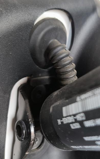
YOU CAN see the protected wiring harness that leads from the rear pillar to the left rear power liftgate actuator on a Ford Escape. Many smaller SUVs only have one power liftgate motor, with the other being a standard gas strut.
THIS SCANNER screen shot from a Nissan shows that it can perform the rear auto back door reset or initialization, without the need to disconnect the battery.
JEFF TAYLOR
RUNNING VEHICLES
Continental belts, hose, hydraulics, tensioners, and timing kits help ensure your customers’ cars and light trucks operate smoothly and reliably. Our precision-engineered parts are built to last and help extend the life of a vehicle without skipping a beat. Continental, your first choice for premium aftermarket products.
RUN STRONGER , LONGER
It’s a Tight Squeeze
I find it more prevalent today than ever before that single-cylinder engine mechanical misfires don’t always mean a loss of compression.
BY BRANDON STECKLER // Technical Editor
THE DATA DOESN’T LIE
WELCOME BACK TO ANOTHER EDITION OF “THE DATA DOESNT LIE,” A REGULAR FEATURE, WHERE I POSE A PUZZLING CASE STUDY.
SOMETIMES SEEING MISFIRES reflected on a scan tool is the result of an ignition system fault. Other times it’s the fault of the fuel injection system. But then again, engine mechanical faults can and do arise
as well. Typical testing for these mechanical faults can usually be discovered by simple relative compression testing. But, if there is no leak (or not a very significant leak), where do you go from there?
Today’s Subject Vehicle
I was providing technical support to a shop facing a 2018 Ford Escape with a turbo-charged, four-cylinder engine. The vehicle suffered from a poor idle concern, intermittent cylinder No. 3 misfire at idle, but no DTCs stored. After preliminary evaluation of scan data (from the driver’s seat), the technician discovered that this speed-density system yielded a total fuel trim value of nearly -20% at idle. Of course, the technician evaluated the MAP values (as this is the main speed-density input responsible for engine load/fuel demand) and found them to indicate really weak intake manifold vacuum of only 8”Hg; however, this condition improved with rpm and load. This was also confirmed with a mechanical vacuum gauge.
Concerned with a timing fault, the technician investigated with a lab scope capture of both the CKP sensor and CMP sensors for correlation (Figure 1). They appeared to be properly timed according to a known good capture. This placed a timing fault at the bottom of the list. Considering the results of the relative compression test did not indicate a loss of compression for the suspect cylinder, the remaining list of possible faults to test for was shrinking (Figure 2).
Pinpointed Testing
The easy-to-perform tests guided the technician to evaluate the No. 3 cylinder
FIGURE 2: The results of the relative compression test show that each cylinder loads the starter motor similarly, inferring the compression is similar from cylinder to cylinder. This also supports the cause of the cylinder No. 3 misfire to not be caused by compression loss.
FIGURE 1: A correlation of the CKP sensor signal to that of the CMP sensor(s) signals can be a great way of inferring camshaft timing. Keeping in mind the limitations of the test, it only truly reflects the timing of the reluctors. If they have lost their reference from their respective shafts, the timing will not be on.
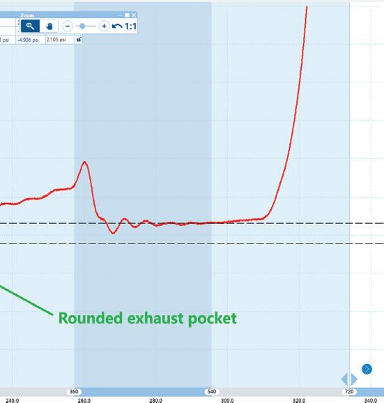
FIGURE 3: Zooming in on this cylinder No. 3 in-cylinder running compression test shows a few details pertaining to the health of the cylinder. The minor pressure differential between the exhaust and intake pocket shows no significant compression loss (backing up the data from the previous RC test). However, the rounded exhaust pocket infers an inability for the exhaust valve to seat properly or even tight exhaust valve lash. If this condition were present, excessive valve overlap could be the cause of the misfire. And since a similar capture was obtained from other cylinders, this could lead to low overall engine manifold vacuum and negated fuel trims, as this engine is experiencing.
CONTINUED ON NEXT PAGE
Solved: 2015 GMC Yukon, Low Compression When Running
From October 2024, Motor Age
BY BRANDON STECKLER // Technical Editor
What would you recommend doing next, given the data points in our previous challenge?
1. Replace the piston/rings/recondition block.
2. Replace the intake valve spring.
3. Machine the cylinder head gasket surface.
4. Replace the exhaust valve spring.
For those of you who chose answer No. 4, congratulations!
Answer No. 1 is incorrect. Although the data shows that the fault is only present during the duration of the intake valve opening, this fault could not be in the low-end of the engine as the fault would be present and showing symptoms whether or not the engine was cranking.
Answer No. 2 is incorrect. Replacing the intake valve spring wouldn’t make sense as a fault with the intake valve or spring would not exhibit during intake valve opening duration.
Answer No. 3 is also incorrect. A cylinder head gasket sealing surface fault isn’t likely to present only during intake valve duration. Furthermore, measurement would show if the cylinder head required machine work to true-up a sealing surface.
The only logical answer is No. 4.
After careful inspection, the exhaust valve spring was found to be broken. During cranking conditions there was enough spring
THE BROKEN exhaust valve spring is the cause of the driveability fault. Keep in mind that a broken spring can present intermittent faults or faults that only occur under certain operating conditions. It’s important to realize that a broken spring can still allow a perfectly passing compression test (or relative compression test) but fail a running test miserably.
tension to return the valve to the rested/sealed position. Under running conditions, the engine is rotating four times as fast and the spring cannot keep the exhaust valve closed.
The spring was replaced and driveability was restored.
more stringently. After all, there is little else that could cause the combination of weak vacuum and significantly negative fuel trims. An in-cylinder compression test was taken for cylinder No. 3 and it was evaluated (Figure 3).
Per the horizontal cursors, the capture shows the weak manifold vacuum but only a minimal amount of pocket differential (no cylinder leakage). However, the exhaust pocket appears to be significantly rounded and immediately caught my attention as cause for concern. A second similar capture was acquired from another cylinder and the results were similar.
The Data Doesn’t Lie
With all the information in front of us, and the desired information not yet obtained, we are faced with deciding how to proceed. Here are some bullet points of what we
know to be factual, and I will ask all of you, diligent readers, for your input on what they mean to you, collectively:
BE SURE TO READ FEBRUARY’S MOTOR AGE ISSUE FOR THE ANSWER TO THIS MONTH’S CHALLENGE AND WHAT WAS DISCOVERED!
REGENERATIVE BRAKES
It takes two systems to slow down.
BY CRAIG VAN BATENBURG
UNDERSTANDING THE PROCESS of changing one form of energy to another is basic physics. In that conversion, there is always a loss of some energy, mainly as heat. That heat generation is usually unwanted and makes the process inefficient. When you put any vehicle into gear and start to drive it, you are building
up kinetic energy. That is the energy stored in a moving object. The heavier the vehicle and the faster it is moving, the more kinetic energy you have. Once you stop accelerating, unless you are going downhill, the vehicle will slow by itself. What is happening? The friction with the tires, outside air, the driveline
• Speed of each wheel
• Speed of the vehicle
• Stopping force requested
• Actual “G” force in real time
• Yaw rate
• Hydraulic pressure at each wheel
What is Regenerative Braking?
• Exact position of the brake pedal
• Brake fluid pressure in the master cylinder
• Pressure in the accumulator
• Vacuum in the brake booster (if equipped)
• How fast the driver pressed the brake pedal
• State-of-charge of the high voltage battery pack
• Other data may also be used
(engine, transmission, wheel bearings, axles, etc.) is turning the kinetic energy into — guess what? More heat. When you step on the brake pedal (or the vehicle may do that for you if you are not paying attention — No texting while driving!) — the brakes are designed to heat up quickly to replace most of the kinetic energy and bring the vehicle to a complete and safe stop. Unless you are pointing downhill, all the kinetic energy is now gone and the cycle repeats itself when you step on the accelerator.
The basic concept of regenerative, or recuperative braking, is to hold off using the conventional hydraulic brakes and let the drive wheels slow down the xEV (a term for any high voltage vehicle) using the high voltage drive motor(s) as a generator. Without modern computer controls, that would not be possible. Imagine only having front brakes and trying to stop a car in all conditions. That would be dangerous as the rear wheel brakes add stability. To have a computer stop the vehicle with both a hydraulic system (think of a four-channel ABS system) and one or more generators in the drive line, the xEV’s computer would need the following data:
A smart dedicated computer would combine the generator and hydraulic brakes seamlessly and stop the xEV. At ACDC we call this computer a BECU or Braking Electronic Control Unit. That is what the majority of OEMs are doing and that changes the way the kinetic energy is given up, so now a car, truck, or even a motorcycle can stop safely without losing all the energy it has built up while driving. The heat normally wasted in friction brakes, or using the internal combustion engine (ICE) to slow down, is ultimately converted into DC electricity and stored in the HV battery pack. High voltage packs are normally kept below 60% on hybrids and below 80% on plug-in vehicles so that the regenerated electricity has some room left in the high voltage battery pack to be stored. Reusing momentum is smart so xEVs are smart. Brake-by-wire (at ACDC we use that phrase loosely) is a term we define in class as meaning the hydraulic action of the friction brakes is being controlled by the BECU all the time. The only time the friction brakes are non-computerized is in a “fail-safe” event. In other words, the BECU is in control of each friction brake, not the driver’s foot.
Wheel End
If you remove a wheel to check the brakes on an xEV, it will look no different than a conventional car or truck. The wheels and axles that connect to the drive motor are the same wheels that will slow down the xEV in regenerative braking mode. As a rule, recuperative braking transitions to hydraulic friction at low speeds, typically between 3 to 7 mph as the kinetic energy left in the xEV is very low, so there is little energy to recycle. Plus, the electric motor would stop the vehicle in segments as the electromagnetic fields swapped poles.
Brake Work
A brake job on most xEVs must be done with high quality parts as there is typically no engine and exhaust noise to mask other noises. Pure EVs are always quiet. Everything you have been taught when replacing pads, shoes, drums, and discs applies to xEVs. You will have return visits from your xEV customers if
the brakes are not repaired with the utmost care and the best parts. Even a slight squeal will annoy them.
Bleeding the Brakes
Once you start working on these regenerative brakes (many of you have already), the equipment you will need includes a good scan tool to “air bleed” the system, and some OEMs may require pressure introduced at the master cylinder reservoir. Removing trapped air in a brake-by-wire system is much like bleeding a four-channel ABS. If you only work on the wheel end, and you do not let the brake fluid run completely out of the master cylinder, then manual bleeding will work in most cases. If the braking problems are caused by the electronics, get your electrical wizard hat on.
Inverter Functioning as an AC-to-DC Processor
What is next is a brief overview of the high voltage generator part of regenerative braking. Anytime a permanent magnet (PM) motor/generator has the rotor spinning, it will generate voltage and current if it’s connected to a circuit. As you have learned in automotive classes, the definition of watts is volts multiplied by amps. Watts is also a measurement of power. The basic principle of recuperative brakes is to switch the high voltage transistors (located on the inverter circuit board) on and off. These transistors were typically IGBT (Insulated Gate Bipolar Transistor) and lately some OEMs are using SiC MOSFET (Silicon Carbide Metal–Oxide–Semiconductor Field-Effect Transistor).
Using duty cycle, the current produced by the HV generator is controlled by these transistors so that the current heading to the HV battery pack is modulated indirectly with the brake pedal. The HV transistors also keep the voltage high enough to charge the HV battery. In its simplest form, the faster you charge the battery, the faster the xEV will slow down. The slower you put energy back into the battery pack, the slower the xEV will stop. How do we control the deceleration of the car or truck with just a brake pedal, while not using hydraulic pressure? It is the programming of the inverter circuit board that performs that function. With more on-time, more current flows and the xEV stops faster. With less on-time it will take longer to stop. This is assuming that there is no hydraulic function at that time in the braking event. This is pretty straightforward and logical, but there is more to it than that. By controlling the output of the generator, braking functions can be controlled. Your scan tool is also extremely valuable as it will get a lot of data into your head and hands quickly. A technician can never achieve great success without a great scan tool. In ACDC’s latest book we go into more detail. We have dedicated an entire chapter to this subject if you want to know more.
How Brake Fluid Is Controlled
Looking at the ACDC HCU (hydraulic control unit) diagram, most OEMs use a two speed 12-volt motor to pressurize the brake fluid into an accumulator, #5 and #6 in the diagram. It will create this pressure before driving or will set a warning lamp if it fails to do so and set codes. The pressure is normally about 2,700 psi, #19. With that much pressure all we need now is to use it, but when?
The HCU has many solenoid valves. Some are on/off valves and others can be duty cycled. The reason for all the valves is to allow the fluid pressure to be precisely metered into each brake line for each wheel brake. Unlike ABS that uses a similar principle to release a locked wheel and allow steering, this system will brake each wheel when needed. It also can be used for traction control (TC), vehicle stability control (VSC), and automatic braking system (ABS). On more modern vehicles, this brake-by-wire system can be used with lane departure or lane assist, adaptive cruise control and automatic braking. To accomplish that, there is a lot going on, so most OEMs use a dedicated CAN bus. When the xEV is in READY, two valves will close, #9 and #10. These on/off valves block the two lines leaving the master cylinder that normally go to calipers or wheel cylinders. Once they are closed the brake fluid in the master cylinder cannot reach anything except a device called a stroke simulator, #4. The stroke simulator is there to fool your foot into thinking it is doing something. It also mimics a vacuum booster. Some “brake feel” is simulated better than others. If valve #8 is opened slowly (duty cycled) while you are stepping on the brake pedal when starting the xEV, it can feel like the booster is being slowly connected to a vacuum source. Some OEMs just open and
THIS MODERN EV has a single unit that controls all hydraulic braking functions.
ACDC
close it. The new owner of a high voltage vehicle expects it to operate like their old carbon-era vehicle did.
Once the brake master computer has determined it has to use some hydraulic brakes for any reason, a message is sent on the CAN bus to activate one or more linear valves (#11 to #14) that are holding back the brake fluid that is under high pressure. These four linear valves allow the brake fluid to get to the wheels, if it is a four-wheel brake system, or fewer valves for a motorcycle. The exact pressure needed is achieved by “duty cycling” the proper linear valve. There are four more linear valves (#15 to #18) that act as pressure release valves, if the hydraulic pressure exceeds the requested pressure. There are four pressure sensors (#22 to #25), one for each wheel, that are incorporated into the HCU and are used for instant feedback in the event that the pressure to any wheel is not correct. The release valves will release the extra pressure back into the fluid reservoir (#3) when the sensor reads too high a pressure. If the hydraulic line pressure to a certain wheel is too low, the ECU will increase the duty cycle to #11, 12, 13, or 14, depending on the wheel pressure. There is one more pressure sensor that reports the accumulator pressure (#9) and will request a higher speed of the pump motor if the pressure is not reached in the timeframe it is programmed to look for.
So, we have mentioned nine linear valves (#8, #11 to #18) and two on/off valves (#9 and #10), and seven pressure sensors (#19 to #25). The brake pedal position sensor (#1) and the master cylinder (#2) provide three sensor readings that are critical to a brake-by-wire system. The master cylinder will produce hydraulic pressure that is measured by pressure sensors #20 and #21. The brake pedal has a sensor that is really two sensors in a single unit (#1) that check each other so the reading is perfect all the time.
As you can see the BMC has complete
THIS DIAGRAM is the basis for a generator control during braking. ACDC ACDC ACDC
STUDYING THIS diagram will help you see how an ABS system can be enhanced.
THE DASHBOARD of an xEV will show the driver when they are in regenerative mode.
TIME TO study OHMs law again?
where you see rust, service the calipers frequently. Our four year old Tesla had caliper issues already.
Thanks for studying more about your future.
IGBT FUNCTIONS as a very fast relay.
control of each wheel. It is just a matter of the Master Brake Computer knowing what the xEV is doing every microsecond and then making extremely fast decisions so the HV battery stays charged up and the wheels do the right thing.
If you work in a part of America
CRAIG VAN Batenburg is the CEO of ACDC, a hybrid and plug-in training company based in Worcester, Mass. ACDC has been offering high voltage classes since 2000, when the Honda Insight came to the USA. When EVs were introduced in 2011, ACDC added them to their classes. Reach Craig via email at Craig@ fixhybrid.com or call him at (508) 826-4546. Find ACDC at www.FIXHYBRID.com.
SIC MOSFET is the latest and greatest transistor.
ACDC
ACDC
ACDC
Bosch Rotating Machines:
More than 100 years of supplying quality products.
A legacy of commitment to customers:
• Bosch offers extensive coverage on Domestic, European, and Asian applications.
• Engineering and quality experts actively develop and validate products for automotive aftermarket, heavy duty, and specialty applications.
• Bosch professionals provide best in class sales support, content, and cataloging.
• All Bosch starters and alternators are backed by Roadside Protect.
Our commitment to quality:
By remanufacturing starters and alternators to meet or exceed OE specifications, Bosch ensures the same high standards of durability and performance as new parts. Our rigorous testing and precision engineering guarantee the reliability you need on the road. Learn more about this high-quality remanufactured option at boschautoparts.com/rethinkreman.
AUTOMOTIVE PRODUCT GUIDE
41610 works on Sheppard M110 steering gears
The Pitman Arm Pullers, Nos. 41450, 41490, and 41610, from Lisle Corporation, are designed to help prevent damage that can be caused by other removal methods. The 41450 works on pitman arms on medium duty trucks and other vehicles with pitman arms held on with a nut. The 41610 works on Sheppard M110 steering gears found on many Class 6-8 vehicles. The 41490 works on Sheppard M100 steering gears found on many Class 6-8 vehicles. The arm pullers are intended for impact use.
Features magnetic brake
The SKF Lincoln 60’ Retractable Power Cord Reel is a high-quality electrical power cord reel with premium features found nowhere else. The 60’ long, heavy-gauge cord is resistant to grease, oil, and weather with three outlets to power a range of needs, including high-current drawing equipment. The reel has a unique magnetic brake that aids in a steady, controlled return which provides safety for the user, others around, and work items in the area. The cord retracts smoothly each time and can be safely stored either mounted on a wall, ceiling, or work bench. This premium model with its non-binding return, will not damage the reel as it delivers the high amperage needed in any setting.
Features specially hardened teeth
The 6” TwinGrip Pliers, No. 82 01 150, from KNIPEX Tools, are forged from high-grade, oil-hardened chrome vanadium electric steel with specially hardened teeth on the gripping surfaces. A pinch guard prevents users’ fingers from being caught, and the pliers use three push-button adjustments that stay in place with a click of the button. The front jaw design grips stripped screws while the optimized side jaw with opposing teeth grips round, square, and hex fasteners. The slim head design allows users to operate the pliers in confined spaces while retaining front and side gripping capacities of 1/8” to 5/8”.
Handle allows remote use
The High-Definition Borescope with 5.5 mm Dual Imager with Handle, No. BK7000COMBO, from Snap-on, features a new wireless handle combo in addition to the BK7000 borescope. The scope and Wi-Fi handle pair instantly out of the box and automatically reconnect with each use. The handle also offers quick USB-C charging and remote use of features, such as initiating image capture, adjusting brightness, and toggling between camera views and picture-in-picture. The borescope also features a 5” capacitive touchscreen and software and feature updates through Wi-Fi. The battery provides up to 1-1/2 hours of runtime.
Made from heavy duty steel
The Performance Tool 23-pc FWD Wheel Bearing Service Set, No. W89307, is designed to service front-wheel drive wheel bearings quickly and efficiently to save on labor costs. The set easily replaces wheel bearings without needing to remove the steering knuckle and strut assembly. It’s made from heavy duty steel and has a black oxide finish for rust resistance. The set works on most FWD bearing assemblies on domestic and imported cars and small pickup trucks and comes in a custom-fit case with slots for each tool to organize, protect, and extend the life of the tool.
Renewable materials need no special handling
Continental has introduced a brake fluid that has been engineered with renewable, raw materials. ATE SecuBrake meets the legal requirements for a DOT 4 fluid without containing boric acid esters. The formulation results in a product that is safer to manufacture and use, while still meeting key performance requirements. Manufactured with renewable raw materials, ATE SecuBrake makes everyday shop work safer as it requires no special handling or storage. It is entirely free of hazardous materials that are subject to labeling requirements.
SmartWeight Elite Wheel Balancer
The Hunter Engineering SmartWeight Elite Wheel Balancer is designed for maximum speed, efficiency, and accuracy. The SmartWeight Elite replaces typical dataset arms with diagnostic lasers that automatically scan the entire inner rim, providing precise locations for weight placement anywhere along the wheel, rather than only the left or right planes. The balancer’s automatic functions include measurement and dimension entry; inside rim runout to identify bent wheels; spoke locations to conceal weights; and a check to ensure the wheel is properly centered on the shaft.
Produces 700 ft-lbs of loosening torque
The AIRCAT 1/2” Angle Impact Wrench, No. 1070, features a jumbo hammer impact mechanism that can produce 700 ft-lbs of loosening torque. It has three forward and two reverse power settings with a feather trigger design. It also features a low-weight aluminum housing with a contoured composite grip, and the tool weighs in at 3.1 lbs. It also uses a 360-degree rotational exhaust to direct the tool exhaust away from the user and work surface.
Suppresses BEV, HEV, and ICE vehicle fires
JohnDow Industries’ Vehicle Fire Blanket enables you to suppress electric, hybrid, and internal combustion engine vehicle fire flames and fumes. Lithium-ion battery fires are very difficult to extinguish and traditional fire repellents do not work due to thermal runaway. When an EV experiences thermal runaway, the battery self-generates heat until it reaches its limit or experiences a catastrophic failure like a fire. This fire blanket is the most efficient way to isolate an EV fire. The fire blanket’s high temperature-resistant material prevents fire from spreading and damaging surrounding vehicles and property while minimizing potential combustion and the fire’s temperature.
VIEW MORE PRODUCTS ONLINE
• Automatic Swing Arm Restraint System (ASARS)
• Expandable Top Beam
• Padded Overhead Safety
• Single-Point Safety Release
• Safety Locks in Each Column
• Dual Hydraulic Direct-Drive Cylinders
• Low-Pro Triple-Telescoping Swing Arms
• Heavy-Duty Aircraft-Quality Equalizer Cables
TECHNICAL SERVICE BULLETINS
RAM TURNING AND CLICKING
This bulletin applies to 2021-2023 RAM 2500, 3500, 4500/5500 trucks equipped with four-wheel drive built on and after Jan. 1, 2021, and on and before March 31, 2023. A ratcheting or clicking noise may be heard while turning. The cause may be an improperly machined front driveshaft. Start the engine. With the 4WD system in 2WD mode and in a safe area, drive the truck between 1-5 mph while turning the steering wheel between a quarter-turn and full lock. If the noise is evident, then place the system into 4WD high mode. Again, drive between 1-5 mph while turning the steering wheel between a quarter-turn and full lock. If the noise persists, replace the front driveshaft using new driveshaft bolts. (Photo: Stellantis)
SUBARU CHANGES TO AXLE SHAFT
been made to the front axle assemblies to address cases of a clicking/cracking sound when driving with the steering wheel in the fully locked left or right position. The size of the joint has been increased to provide added durability. Replace the affected side with the newly designed drive axle shaft assembly. The assemblies are not required to be replaced in pairs. Replace only the affected side. New design front drive shaft for Outback is P/N 28321AN030. Forester shaft is P/N 28321SJ010. Both require one-time-use nut P/N 902170049.
(Photo: Mitchell 1)
JEEP NOISY STEERING COLUMN
from the tailshaft of the steering column while turning. Use a stethoscope or chassis ears to listen to the lower steering shaft near the energy absorbing slip joint, on the interior side, near the front bulkhead while the steering wheel is turned. If the noise is coming from the energy absorbing slip joint area of the lower shaft, replace the steering column assembly. (Photo: Jeep)
BMW WET FEET
This bulletin applies to 2018 BMW X3 and X4 sports activity coupes. Water ingress may occur at the driver-side footwell. Check that the steering shaft collar is correctly positioned and correct as needed. Check that the plain bearing is correctly seated in the sleeve. Spray universal lubricant spray P/N 83 19 2 446 565 between the plain bearing and the steering shaft to aid in installation. Perform a leakage test. (Photo: Mitchell 1) INFORMATION COURTESY OF MITCHELL 1
This bulletin applies to 2020-2023 Subaru Outback and 2019-2023 Forester vehicles. A design change has
This bulletin applies to 2020-2021 Jeep Wrangler and Gladiator vehicles built on or after July 15, 2020, and on or before March 2, 2021. A noise may be coming
CADILLAC COOLANT SENSOR
A small number of 2021 Cadillac XT4 and XT5 vehicles may have a coolant inlet pipe that may present an obstructed threaded hole for the coolant temp sensor which could result in the check engine light coming on or a potential coolant leak.
Perform a coolant system leak check. If the cooling system maintains the rated pressure for at least two minutes, then locate the coolant temperature sensor in the engine coolant thermostat housing inlet pipe at the front of the engine. Pressurize again with the EN-24460-A cooling system pressure tester and observe the sensor to see if it is leaking. If the temp sensor is leaking, replace the thermostat housing inlet pipe using P/N 55507975 and sensor 55488246.
(Photo: GM)
NISSAN ENGINE STOPS
Owners of 2020 Nissan Kicks vehicles may complain about an engine shutoff when coming to a stop. The MIL may not be on, and the engine is easily restart-
ed. There may be no stored DTCs. Confirm the current ECM part number. Adjust the base idle to 0 rpm with CONSULT-III plus and reprogram the ECM. If the ECM part number matches one of the part numbers listed below, proceed to reprogramming. If it does not match, ECM reprogramming is not needed. Proceed with further diagnostics.
2020 Kicks: 23710-5RW2d; 5RW3D, 5RW4D, 5RW5D
After reprogramming, perform a 10-minute test drive in order to meet the following idle air volume learning conditions:
• Engine coolant temperature of 158212 degrees Fahrenheit
• Battery voltage of more than 12.9V at idle
• Transmission warmed up When reprogramming is complete, you will be able to perform throttle valve closed position, idle air volume learning (IAVL), accelerator closed position and DTC erase. If idle air volume learning does not complete, check the idle speed adjustment with C-III plus Work Support and confirm that the idle is set to 0 rpm. Once idle speed is set to 0 rpm, IAVL can be completed. (Photo: Nissan)
FORD ECOBOOST DTC
Some 2018-2020 Ford EcoSport vehicles equipped with a 1.0L EcoBoost engine may exhibit a recurring illuminated
MIL with DTC P04DB. This may be due to the software in the PCM. Reprogram the PCM with the latest available software. (Photo: Ford)
MAZDA DRIED COOLANT NORMAL
Some 2016-2022 Mazda CX-3, 20162022 Mazda2, 2019-2022 Mazda3, 2017-2021 Mazda6 and 2017-2020 CX-5 vehicles may exhibit accumulation of dried coolant around the water pipe.
This is caused by a gap between the housing and pipe due to a press fitting during manufacturing. The accumulated coolant is solidified and plugs the gap in a high temperature environment and the seepage is stopped and does not progress. This is normal and does not require a part replacement. Clean off the dried coolant from around the pipe with a wire brush. (Photo: Mitchell 1)
NO. 155 Scope Sample Rate
BY BRANDON STECKLER // Technical Editor
WE’RE BACK WITH ANOTHER GOLDEN nugget from the trenches of automotive diagnostics.
This time, it’s regarding one of the most overlooked aspects of digital storage oscilloscope (DSO) implementation — scope sample rate.
Although there are many important aspects to selecting the scope that is right for you and your shop, one of the most important is scope sample rate. A scope (like many other circuit measuring devices) is one that takes samples (like photos from a camera) and plots them on a graph (the domain you’ve chosen to measure in, over a period of time selected). Sample rate refers to the scope’s ability to capture data and is reflected in a rate of “samples per second.”
What many technicians fail to realize
is that the scope sample rate diminishes as you request the scope to perform more work. This is best described by way of example.
Suppose a scope is capable (at its fastest) of capturing data at a rate of 1 million samples per second (1Ms/sec). If this scope is equipped with (and is using) four channels, the sample rate is split between the channels (due to a common scope construction and design). So, the 1Ms/sec becomes only 250,000 samples per second (or 250ks/sec).
If the scope utilizes eight channels, this characteristic becomes worse (1Ms/ sec becomes 125ks/sec). Again, each time another channel is utilized the sample rate is split again.
Furthermore, the more time that is captured (a longer time base versus a
shorter time span) the more this characteristic can limit the scope’s sample rate capture capability. With that, a perfectly healthy signal can be so deficient of sample rate, it can lead to a misdiagnosis. The point?
We must always understand the limitation of the tool we choose to implement.
All scopes (and other tools) have limitations, no matter how popular or expensive they might be. Taking the time to identify these limitations is the difference between a “homerun” and a “swing-and-a miss.”
Stick with master diagnostician Brandon Steckler and learn what it means to discover sample rate limitations to maintain your accuracy and boost efficiency, on this episode of The Trainer!