The new ANSI/NEMA C137.10 standard is designed to keep streetlights on during extreme weather. But in normal times, it also creates opportunities in the smart cities market. Read more on pg. 32
Planning
Job-Site
Lighting Installations pg. 10
Electrifying Your Fleet pg. 18
Cultivating Healthier Spaces Through Lighting Design pg. 38
Quick Guide to Emergency Lighting pg. 50
Servicing Equipment in Challenging Locations pg. 54
NEC Requirements for Conductors pg. 58
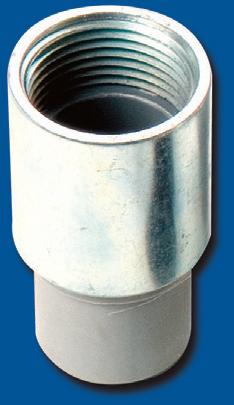
PVC Conduit Hub
Benefits:
ꞏ Features a patented, low-profile design with an ergonomic tightening mechanism & O-ring seal
ꞏ Listed to UL 651 & UL 50E
ꞏ Conforms to NEMA TC 3
Versatile Tightening Mechanism Maximizes Internal Junction Box Space O-ring
Completely Nonmetallic
The new ANSI/NEMA C137.10 standard is designed to keep streetlights on during extreme weather. But in normal times, it also creates opportunities in the smart cities market.
How designers are using breakthroughs in biologically effective lighting to mimic natural light cycles and improve human health at home and at work
Modifications to solid-state lighting’s qualified products lists aim to streamline LED adoption with smart lighting controls, unlocking even greater energy efficiency and compatibility.
How integrated controls and LED advancements make
lighting installations
your fleet
ECMWEB.COM
With its exclusive online content, ecmweb.com is a valuable source of industry insight for electrical professionals. Here’s a sample of what you can find on our site right now:
10 WAYS NFPA-70B AND THERMOGRAPHY CAN BE YOUR BEST FRIEND Test & Measurement Real-world examples from the field demonstrate how thermography can catch problems before they spark. ecmweb.com/55275799
UNDERSTANDING ADVANCED RISK FACTORS FOR ELECTRICAL SAFETY WITH LANNY FLOYD Video In this video, filmed at the NETA PowerTest 25 show, Ellen Parson interviews Lanny Floyd on electrical safety topics. ecmweb.com/55278241
SHOW OFF YOUR SKILLS! BECOME AN EVERYDAY ELECTRICIAN INFLUENCER
The Everyday Electrician We’re on the hunt for real-world electricians to share their best tips, tricks, and on-thejob insights as part of our Everyday Electrician video series. ecmweb.com/55278724
Editorial
Group Editorial Director - Buildings & Construction: Michael Eby, meby@endeavorb2b.com
Editor-in-Chief: Ellen Parson, eparson@endeavorb2b.com
Media Account Executive – Classifieds/Inside Sales: Steve Suarez, ssuarez@endeavorb2b.com
Production and Circulation
Production Manager: Josh Troutman, jtroutman@endeavorb2b.com
Ad Services Manager: Deanna O’Byrne, dobyrne@endeavorb2b.com
User Marketing Manager: James Marinaccio, jmarinaccio@endeavorb2b.com
Endeavor Business Media, LLC
CEO: Chris Ferrell
CDO: Jacquie Niemiec
COO: Patrick Rains CRO: Paul Andrews
CMO: Amanda Landsaw CALO: Tracy Kane
EVP, Group Publisher – Buildings, Energy & Water: Mike Christian
Electrical Construction & Maintenance (USPS Permit 499-790, ISSN 1082-295X print, ISSN 2771-6384 online) is published monthly by Endeavor Business Media, LLC. 201 N. Main St 5th Floor, Fort Atkinson, WI 53538. Periodicals postage paid at Fort Atkinson, WI, and additional mailing offices. POSTMASTER: Send address changes to Electrical Construction & Maintenance, PO Box 3257, Northbrook, IL 60065-3257. SUBSCRIPTIONS: Publisher reserves the right to reject non-qualified subscriptions. Subscription prices: U.S. ($68.75 year); Canada/Mexico ($ 112.50); All other countries ($162.50). All subscriptions are payable in U.S. funds. Send subscription inquiries to Electrical Construction & Maintenance, PO Box 3257, Northbrook, IL 60065-3257. Customer service can be reached toll-free at 877-382-9187 or at electricalconstmaint@omeda.com for magazine subscription assistance or questions.
Printed in the USA. Copyright 2025 Endeavor Business Media, LLC. All rights reserved. No part of this publication may be reproduced or transmitted in any form or by any means, electronic or mechanical, including photocopies, recordings, or any information storage or retrieval system without permission from the publisher. Endeavor Business Media, LLC does not assume and hereby disclaims any liability to any person or company for any loss or damage caused by errors or omissions in the material herein, regardless of whether such errors result from negligence, accident, or any other cause whatsoever. The views and opinions in the articles herein are not to be taken as official expressions of the publishers, unless so stated. The publishers do not warrant either expressly or by implication, the factual accuracy of the articles herein, nor do they so warrant any views or opinions by the authors of said articles.
Reprints: Contact reprints@endeavorb2b.com to purchase custom reprints or e-prints of articles appearing in this publication.
Photocopies: Authorization to photocopy articles for internal corporate, personal, or instructional use may be obtained from the Copyright Clearance Center (CCC) at (978) 750-8400. Obtain further information at www.copyright.com.
Archives and Microform: This magazine is available for research and retrieval of selected archived articles from leading electronic databases and online search services, including Factiva, LexisNexis, and ProQuest.
Privacy Policy: Your privacy is a priority to us. For a detailed policy statement about privacy and information dissemination practices related to Endeavor Business Media products, please visit our website at www.endeavorbusinessmedia.com.
Please Note: The designations “National Electrical Code,” “NE Code,” and “NEC” refer to the National Electrical Code®, which is a registered trademark of the National Fire Protection Association.
Corporate Office: Endeavor Business Media,
Hartford Steam Boiler Inspection and Insurance Company
Assemble Conduit Above TrenchNo Workers BelowPrevents Injuries and Deaths. Also Allows Digging a Narrower Trench for Less: Excavation, Concrete, Slurry, Backfill & Shoring.
Shining a Light on The Everyday Electrician
By Ellen Parson, Editor-in-Chief
Calling all electricians interested in sharing their technical knowledge to help their peers work smarter and safer by creating customized technical video content. We’re on the hunt for electricians just like you to share valuable insights, best practices, tips/tricks, and time-saving techniques from the field through the lens of your video camera or smartphone.
It you’re not already familiar with EC&M’s “The Everyday Electrician” short-form video series, it’s time to check it out (www.ecmweb.com/members-only/videos/theeveryday-electrician). Since launching this initiative in January 2024, it really has taken on a life of its own through our social media channels (Instagram, YouTube, and TikTok). Gaining significant traction among industry professionals very quickly, this platform features real-life job site experiences from Trevor Ottmann, President of 3/0 Electric, an electrical contracting firm based in Bennet, Neb., that focuses largely on commercial/ industrial jobs and agricultural electrical work. Providing a day-in-the-life glimpse into Trevor’s work, viewers have loved learning from his troubleshooting strategies, tips and tricks, and electrical best practices in an easy-to-digest, relatable format.
EC&M is looking to expand this concept to encompass more “everyday electricians,” representing different market sectors to showcase the unique and diverse work our audience tackles on a daily basis. This is your moment to shine. No matter what electrical niche you specialize in, we’d like to hear from you — the goal is sharing your skills with a growing community of electrical professionals who are passionate about their craft.
The purpose of this call for content creators is simple: Create a professional space where electricians can exchange real-world knowledge in an accessible format that encourages interaction, engagement, and information sharing. By participating, contributors not only help fellow electrical professionals but also gain exposure to EC&M’s massive online audience. It’s an opportunity to establish credibility, connect with industry peers, and spark meaningful conversations about the realities of electrical work — the good, the bad, and the ugly.
Submitting is easy. Electricians interested in being featured simply need to record a short (two-minute or less) vertical video showcasing a tip, trick, or best practice from the job site. After filling out our video submission form online at https://bit.ly/3EeIPrD, selected participants will be contacted directly by the EC&M editorial team and potentially featured across our social media platforms, newsletters, and website. Although there is no monetary compensation for this opportunity, the potential to reach a vast audience and elevate one’s industry standing in the trade is invaluable.
Are you ready to step into the spotlight? EC&M’s “The Everyday Electrician” is waiting for you to get involved. Whether you’re a seasoned veteran or a rising star, your electrical expertise is needed. Submit your video today for a chance to become a recognized voice in the electrical community!
Alyssa B.
Daniel C. SupplyHouse Team Member
Planning Job-Site Lighting Installations
Considerations when planning for luminaires and preventing unknowns from impacting your installation
By Dr. Heather Moore, MCA, Inc.; contributions from Kevin Lytle and Kevin Lytle, Jr., Allfab Group
Handling and preparation
Receive luminaires at job site
Move luminaires to install area
Unpackage luminaires
OGet tools and materials needed to work
f all the things that electricians produce, light is the most visible (no pun intended) to the customer and consumer. While they also bring “the power,” those outlets, internet connections, and safety systems don’t deliver the same aura to space as luminaires and controls. However, bringing that light can be one of the most painful parts of a job for the electrician.
Luminaires and devices are installed in the second half of a project and can bring a myriad of productivity-killing issues. The supply chain also contributes — from picky customers to engineering changes or mistakes — in addition to the delays in getting the luminaires made and moved without damage.
Based on our JPAC® database of thousands of projects, luminaires contribute
Luminaire install
Assemble luminaire accessories
Mount luminaire supports Install luminaires
Make connections
Complete and Demobilize
Test and troubleshoot Clean up
Labeling
between 10% and 20% to a project’s hours, depending on the nature of the work. It is one of the most commonly tracked labor codes, but the largest code by hours when compared to conduit and wire. Therefore, the weight of luminaires alone does not drive the project outcome; however, the issues can erode the gains of a great “first half” (e.g., underground, rough-in, distribution, etc.) without a solid plan. This article will share real examples of luminaire headaches. It will also share solutions for making your plan for luminaires as illuminating as the light they produce.
Allfab Group, building on decades of highly productive projects led by its president, Kevin Lytle, attributes its success with luminaires on projects to three things:
• Supplier and manufacturer coordination and planning
• Off-site receiving, delivery, and storage
• Just-in-time delivery and placement on the job site
These all sound like no-brainers; however, they take effort and focus in planning up front and throughout the project.
PLANNING FOR LUMINAIRES
The process of planning luminaires is a long one with a lot of unknowns along the way. Lytle starts by looking at the submittals to get an idea of what luminaires may need approval from the customer. With experience with certain luminaire types or lighting control systems, the work and effort can be planned much more easily. The work breakdown structure (WBS)
Fig. 1. This work breakdown structure (WBS) can be used for installation of any type of luminaire.
Luminaires
WBS for Luminaires
JOB-SITE INTELLIGENCE
Luminaires represented almost half of the project’s hours
Fig. 2. The level of breakdown on Lytle’s luminaire WBS reflects the thought (and research) behind each luminaire type and installation area, allowing better planning for those luminaires and observing their percentage completion more accurately for measuring productivity.
process is perfect for getting the “knowns” on paper, and then leaving some space for follow-up approved submittal review. See Fig. 1 (on page 10) for a sample of a WBS for luminaire work that can be used for planning any luminaire type. Figure 2 shows a sample of how Lytle’s luminaire WBS translates into JPAC® for tracking. The level of breakdown reflects the thought (and research) behind each luminaire type and installation area, allowing better planning for those luminaires and observing their percentage completion more accurately for measuring productivity.
Other considerations during your WBS for luminaire work include:
• How will the luminaires be delivered?
• What will the work conditions be for moving and installing the luminaires?
• What hardware will come with the luminaires? Will/can any of that be pre-assembled?
• What are the lighting controls (e.g., wired, wireless, Bluetooth, etc.)?
The key for luminaires, and any work that will occur “later in the job,” is to
Unexpected Install Conditions
continue to revisit the WBS often. Revisiting the work (and potentially the effort) as more becomes known about the luminaires and their installation, is crucial to the process. This is also why it’s critical
to release luminaires as soon as they are approved so that you can lock in the plan, including coordinating quantities and staging with suppliers, and avoid supply chain delays. Changes to that plan can
WBS Translation into JPAC®
The original plan called for scaffolding to be used at this location, which featured sloped ceilings and floors.
A change was made on site to build a wedge platform and rent a scissor lift.
Fig. 3. The lighting plan had to be changed to accommodate the sloped floor and ceiling.
then be tracked accordingly. Luminaires should also be incorporated into a project schedule, linking the impact of submittals, release, and up front decision delays to downstream installation impacts that may be months away.
TRACKING THE PLAN AND MEASURING DEVIATIONS
Once the luminaires are ordered, they sometimes get forgotten until it is time to release them to the job site. The conditions of their installation, packaging, and kitting can all have changed from what you expected in the initial WBS. Missing parts, damages, and plain “wrong luminaires” all bring wasted effort and time late in the game. Figure 3 on page 12 and Fig. 4 show samples of work required in an area that was not part of the original plan. These differences will show up immediately with the usage of ASTM E2691.
Figures 5 and 6 (on page 14) show data from one of Allfab’s projects. The project was a remodel, which brought its own challenges with difficult installation conditions. Savings were realized on this project by the use of Bluetooth-based lighting controls. Although this was a newer technology (requiring some studying/learning up front), Lytle found it simpler than running low-voltage cables and worrying about switch legs. According to Lytle, this type of system is also easier to troubleshoot because you don’t need to trace down damaged or faulty wiring.
Lytle also emphasizes how much “trash” is associated with luminaire packaging. For example, with 16-ft to 20-ft luminaires,
Installation in Hard to Reach Places
Long luminaire lengths to install 40’ off the ground
moving and cleaning up this trash drove his luminaire cost code into the ditch (see Fig. 5). Per the checklist below, this can all be avoided based on how luminaires are ordered.
CHECKLIST TO AVOID RISKS IN FIXTURES & LIGHTING CONTROLS
Use WBS up front and revisit every 25%.
Review submittals and research/follow up with distributor and/or manufacturer for:
TIME SYNC HUB
In Critical Power Facilities precision data Is essential! Accurate time stamped data from the Trystar Time Sync Hub ensures any updates or changes to the power system are based on solid and reliable data.
Features:
- Converts Common Time Protocols
- Simple Installation with No Additional Software Needed
- Time Sync In via GPS, PTP, NTP, IRIG-B, DCF77
- Time Sync Out via PTP, NTP, IRIG-B, DCF77, 1per10 and ASCII
Luminaire
Fig. 4. Job-site lighting can be difficult to install.
5. Luminaire labor code productivity declines due to several issues noted in JPAC®.
6. SIS® captures further detail and impacts from luminaire issues.
See if lighting internal controls can be installed at the factory.
Luminaire packaging and shipping expectations.
Plan for non-installation work (what, who, where, when these things should happen):
Research, understanding how the luminaire/controls work. Receiving (including inspection and damage).
Site delivery details/plan (focus on reduced packaging options and breakdown quantities for less “bulk movement”). Assembly.
Testing and troubleshooting.
Cleaning and labeling. Supply chain impacts:
Review and communicate the schedule (yours and the distributor/manufacturers), make decision-making delays visible early, and use the schedule to set optimal delivery times.
Request job packs (kitting, packaging breakdown of luminaires when possible to avoid excessive trash (Fig. 7).
Tracking — separate labor code, detailed reason code.
Dr. Heather Moore is the vice president of customer care and support at MCA Inc., in Grand Blanc, Mich. She can be reached at hmoore@mca.net.
Kevin Lytle is President of Allfab Group in Omaha, Neb. He can be reached at klytle@allfabgroup.com.
Luminaires Without Job Packs
Sample from Allfab Project
Fig. 7. Differences between luminaires delivered with vs. without job packs.
Luminaires Delivered Without Job Packs
Unpackaged and Installed Luminaires
Luminaires Moved and Staged for Unpackaging and Assembly
Luminaires Delivered with Job Packs (less garbage/waste — can go right to install) vs.
15- or 20-amp, TR & TR/WR $6.00 each/$300 per case of 50 Purchase in bulk to receive additional
10 cases = 5% off 20 cases = 10% off 30 cases = 15% off 40 cases = 20% off 50 cases = 25% off
Vist
Warehouse Pick Up Price $19.55
Warehouse Pick Up Price $27.57
Price $32.57 2X4FT Panel
Product Features:
• Backlit technology that offers even lighting distribution without shadowing.
• Color selectability allows for changing between 3500K, 4000K or 5000K.
• Wattage/Lumen selectable versions: three different lumen outputs in the same product.
• Emergency battery back up optional.
• The range input voltage 120-277V.
• 125 lumens per watt -CRI>80
• DLC Premium/DLC Standard
Areas of Application
The backlit Panels are the high efficiency solution for offices, schools, hospitality and retail areas.
Electrifying Your Fleet
An examination of reliable local power generation solutions
By Brad Tolbert, ABM
Fleet electrification provides opportunities to achieve climate goals while delivering social, financial, and environmental benefits to individuals, businesses, and communities. But the road to successful electric vehicle (EV) implementation is not without obstacles. EV fleets need to work all the time under varying conditions to ensure optimal uptime while maintaining energy efficiency.
Consequently, electric vehicle service equipment (EVSE) can’t just be “tacked onto” an existing operation. Rather than a “new standalone addition,” it requires a thoughtful and forward-looking approach to seamlessly integrate into the overall facility. Ensuring the type of reliable power needed for an electrified fleet is critical. Luckily, several new and emerging
solutions promise to deliver clean and reliable local power generation.
THE CHALLENGES
The availability and reliability of the power needed to support electrified fleets is a primary roadblock for many commercial fleet operators. It’s important to look at where that power comes from, how much it will cost, and whether it will be available when needed.
Today’s energy landscape is complex. Projections indicate that the electricity demand will surge by 50% during the next two decades — with no signs of slowing down. According to Grid Strategies, the U.S. electric grid is not prepared for this level of significant load growth. The sheer amount of power needed to keep trucks charged and running 24/7 can be substantial.
This poses a key risk for reliability in EV infrastructures, particularly in mission-critical situations.
In addition, most fleet operators have become accustomed to fairly predictable fuel costs, since many take advantage of long-term supply arrangements. By contrast, electricity grid costs can vary and result in unpredictable spikes. This adds an extra layer of complexity when it comes to the planning and timing of fleet charging. As a result, many fleet charging operations are turning to local power generation.
INTELLIGENT MICROGRIDS, THE ENERGY INSURANCE POLICY
Microgrids are nothing new — rural communities have relied on them for decades. Increased affordability and shifting regulations are allowing for
CableStop™ TRANSITION FITTINGS
• TRAY CABLE
• FMC
• MC & PVC MC
• AC90 & ACWU
• TECK Cable
Perfect for data center remote power panel feeds, panels, equipment feeds and EV Chargers in parking garages, Arlington’s Listed CableStop™ Transition Fittings deliver the efficient, cost-effective way to transition feeder cables to 2.5", 3" and 3.5" EMT, IMC and RMC conduit in protective drops, risers and feeds to panels and equipment.
Available with set-screw or compression connections into 2.5", 3" and 3.5" conduit, they ship with multiple end stop bushings that vary the size of the opening – along with a free template select the right bushing for the cable. FROM
Our new CableStop fittings integrate our patented, versatile and SKU-reducing 8412 series cable fittings, with Arlington conduit fittings, allowing for easy transitions to larger knockout sizes.
EV UPDATE
more of these microgrids to be powered by renewable energy methods.
EV Infrastructure
This twice-a-month e-newsletter tracks the development, design, installation, and safe operation of electric vehicle supply equipment and systems.
Topics covered include:
• Applying NEC requirements
• Industry news and trends
• New products
• Federal investment allocation
• National EV charging infrastructure buildout development
Subscribe Today
See all of our EC&M e-newsletters at www.ecmweb.com
A common misconception is that microgrids can completely offset power from the grid. In reality, they are designed to provide peak load shaving and system resiliency. Coupled with an EV infrastructure, microgrids can offer more flexible and reliable energy management.
When compared to a traditional microgrid for a building system, microgrids for fleet electrification present new challenges. Most notably, microgrids for fleet electrification are not modeled on an existing load, but rather anticipated demand, which can make reliable load-based modeling more difficult.
However, an “intelligent” microgrid uses control systems to manage, store, charge, and discharge energy across the system. These controls monitor supply and demand, track real-time electricity prices, and create efficient charging schedules, considering factors like time of use (TOU) and peak day rates. For example, when electric fleets plug in, demand may increase significantly overnight, making strategic energy management crucial.
The system can buy power from the grid during low-cost periods while storing self-generated solar power for later use. When prices rise, it discharges stored energy, keeping costs stable. It can also operate independently, ensuring continuous power during outages and disruptions, and improving efficiency, cost control, and reliability. Conversely, fleets often permit charging flexibility within defined boundaries, providing a unique dispatchable resource that can be tuned to fit the needs and energy resources of the customer.
A NEW CATEGORY OF LOCAL POWER GENERATION
Linear generator technology is proving to be an innovative solution for EV infrastructures by providing flexible, resilient, and cost-effective on-site baseload power. Linear generator technology provides fuel flexibility, meaning they can directly run and switch among traditional fuels like natural gas or propane. Or, they can use low- and zero-carbon fuels such as RNG, biogas, hydrogen,
and ammonia. Its backup capabilities ensure power through hurricanes, sub-zero snowstorms, excessive heat, and other extreme conditions. Based on capital expenditures and operating costs, linear generators can provide a competitive levelized cost of ownership compared to grid power or other alternatives in certain regions.
The technology can also be quickly deployed at scale, which is ideal for large fleet operators looking to quickly and cost-effectively deploy resilient EV charging infrastructure while reducing emissions and working toward netzero goals.
What’s more, linear generators deliver a more “future-proof” path. While the dominant sources of fuel for local power generation today are well understood, new and exciting fuels are on the horizon. These solutions allow for flexibility and integration of new fuels as they become available — all without having to replace or retrofit existing equipment.
EXPERTS WILL POWER THE FUTURE
As companies look to integrate EVs into their operations, a well-thought-out plan for infrastructure is essential to ensure safety, reliability, and long-term success. The integration of on-site power systems will play a critical role in optimizing energy use, lowering costs, and maintaining system resilience.
The good news is that energy management is becoming more flexible, ensuring that fleet electrification is not only sustainable but also cost-effective. To ensure a seamless transition and maximize the benefits of fleet electrification, many companies will be moving forward by working with experienced consultants, engineering firms, and electrical contractors to create a future-proof infrastructure that meets both operational and environmental goals.
Brad Tolbert is vice president of sales –mission critical, electrical power solutions, eMobility at ABM. He holds a bachelor of science in agricultural business and applied economics from the College of Food, Agricultural, and Environmental Sciences at the Ohio State University.
Super-secure installation!
Our lowest cost, L-shaped fan/fixture box mounts to single or double joists with a captive center screw. No loose parts!
screws ship captive, ready to install box and bracket.
For 1/2" or 5/8" drywall
Fast, easy installation
• Locator posts assure proper positioning of fan/fixture bracket
• 2-hour Fire Rating
This convenient combo box has power and low voltage openings in the same box for a neat, time-saving installation.
The box adjusts to fit wall thicknesses from 1/4" to 1-1/2". Mounting wing screws hold it securely in place.
• 2-Hour Fire Rating
• Low voltage side has a combo 1/2" and 3/4" KO for raceway
• Includes NM cable connector (power side)
Product info aifittings.com/ landing/ combo-boxes
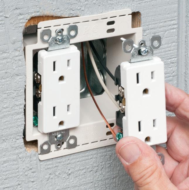
In a tight spot? Arlington’s new SNAP-TITE® Transition Fittings offer the time-saving solution for installing additional conduit or cable in an already congested panel. They allow installers to work around tightly spaced, installed fittings in a panel, box or enclosure – where installing and tightening additional locknut fittings would be
Convenient, Time-Saving snaps into a 1/2" knockout and connects 1/2" trade size threaded fittings or pipe. aifittings.com/landing/2450st
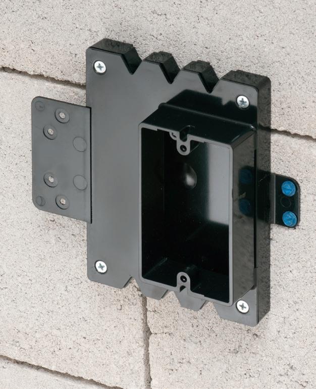
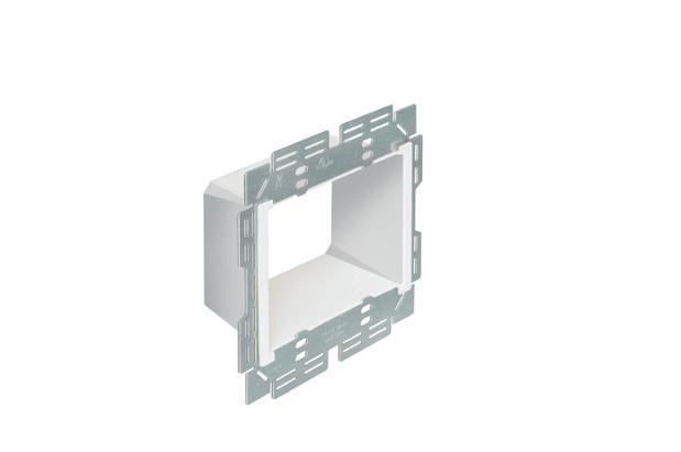
Large Volume FURRED WALL BOX
Arlington’s new Furred Wall Box™ kit makes challenging outlet box installations fast and easy!
Versatile mounting options Our high strength FSB series outlet box kits are designed for use with existing 1x2 drywall furring strips – but can also be mounted directly to a concrete block wall between furring strips. Place the box or outlet where it’s needed.
Integral cable securement – No pullout! Accommodates GFCI and USB receptacles. Convenient kits simplify ordering of FSB1 and FSB2.
High-strength No breakage in cold weather
Integral Mounting Flanges
FSB2
FSB1 Single gang on Block Wall
Low Profile
NEW FSB12 * FSB22
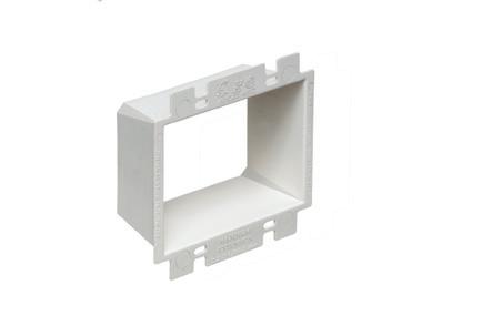
ADD OUR BOX EXTENDERS to BROADEN APPLICATION and USE
Furring strip flange Mounting Bracket
Base Assemblies for 1/2" Wall Thickness & Standard Depth
Install on 1x2 Furring Strips or Block Wall with 1/2" Drywall
Block wall flange Mounting Bracket
FSB22 Two-gang
Our NEW Low Profile single and two-gang Furred Wall Box™ base assemblies have 1/2" raised ring for use with standard wall plates.
They combine with Arlington’s Box Extenders to deliver installation solutions for wall thicknesses from 1/2" to 1-1/2" and varying device depths
One-gang FSB12
• Integral cable securement – No pullout!
• For standard and GFCI devicesUses standard wall plates
• Single gang FSB12 - 17.0 cu. in. Two-gang FSB22 - 20.5 cu. in.
Add our BOX EXTENDERS for these specific conditions...
1 if Total Wall Layer Thickness is GREATER than 1/2" (up to 1-1/2") Add BE1 or BE2
+ BE1
if Using a Deep Depth Device with 1/2" Wall Thickness
Add BES1 or BES2
or Dimmer
LIGHTING & CONTROL
Choosing the Right Lighting System
Three steps to follow when considering lighting system upgrade options
By Dan Kuhl, Evergreen Energy Partners
As an installer, selecting the right lighting system can be a challenge — balancing client expectations, adhering to building codes, and navigating existing wiring constraints to name a few. It’s important to understand both the technical aspects of the system and how to communicate its benefits effectively to customers. To simplify this process, we’ve outlined a few key steps to identify which benefits you need from a lighting system upgrade and how to use this information to build a solid business case for your clients.
STEP NO. 1: IDENTIFY THE KEY BENEFITS
To start, you’ll need to understand your customer’s pain points. Consider the
benefits you can offer while not creating additional challenges. There are smart but simple lighting systems utilizing wireless technology that reduce
flexible and can accommodate space changes and rezoning without rewiring. They also streamline code compliance and allow for quick light-level
Whether you’re working with new construction or retrofitting an existing space, LLLCs can be customized to fit the needs of almost any project.
labor, material costs, installation time, and set-up — all while providing your customer with a fully adjustable solution that maximizes the benefits of LEDs. Additionally, these lighting systems are
adjustments with app-based tools, enhancing user comfort.
Luminaire-level lighting controls (LLLC) easily deliver these benefits. It’s a type of networked lighting control
Courtesy of NEEA
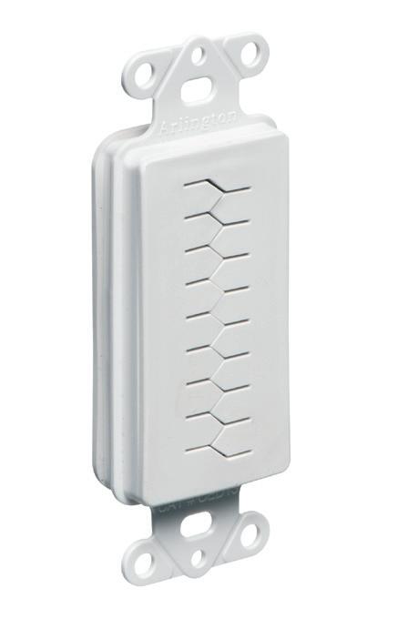
Arlington’s Low Voltage Mounting Brackets are mounting of Class 2 communications, computer and cable TV wiring and connections.
Introducing for EXISTING or RETROFIT construction...
Our
• Extra rigidity and stability where performance and visibility are important or critical
• Threaded holes for easy, fast device installation
• Adjustable bracket for 1/4” to 1” wall board thicknesses
The LV1S PLATED STEEL mounting bracket, with its unique X-shaped bracket design, provides excellent stability and secure installation of low voltage devices in 1/4" to 1-1/4" walls - without an electrical box.
Try them all! Metal and Non-metallic for retrofit, nail or screw-on for new work, and others!
Threaded Holes for easy device installation
LIGHTING & CONTROL
Illumination Insider
This e-newsletter tracks the research, development, design, installation and operation of all types of lighting and control products. This monthly product is geared toward professionals working in the industrial, commercial, retail, residential, institutional, health care, government, and utility market sectors.
Subscribe Today
See all of our EC&M e-newsletters at www.ecmweb.com
(NLC) system that integrates both sensors and load controllers into each luminaire, providing unparalleled flexibility, control, and energy savings. Unlike traditional luminaires requiring multiple switch legs, LLLC luminaires only need a single power connection, reducing labor and wiring complexity. Whether you’re working with new construction or retrofitting an existing space, LLLC can be customized to fit the needs of almost any project.
A flexible custom solution was what the Vancouver Innovation Center needed when it came time to upgrade its lighting system in Vancouver, Wash. With tenants moving in and out, they needed easy installation, simple commissioning, and the ability to reconfigure the space for any size tenant. After weighing the different lighting solutions and products, they ultimately chose a LLLC system.
STEP NO. 2: LEVERAGE YOUR LOCAL ELECTRIC UTILITY
Local electric utilities often have specialists who can help point you toward the best solutions for your project and can confirm whether your project qualifies for an incentive. These incentives can significantly offset costs, making LLLC an even more compelling choice. If you’re in the Northwest, the Northwest Trade Ally Network is another great resource for learning about lighting control systems. Be sure to compare the pricing of LLLC versus standard LED luminaires, and make sure the comparison includes electric utility incentives.
Fluke Corp., a multi-national manufacturer specializing in electronic test measurement based in Everett, Wash., wanted to upgrade its lighting system. They contacted their local electric utility, Snohomish County PUD, to learn more about their options. After analyzing energy savings potential, they discovered that retrofitting their current LED luminaires with the same LLLC system would yield more than enough savings to qualify for a utility incentive. Understanding the full savings potential of this upgrade — in terms of energy savings and utility incentives — helped influence the project’s decision-makers, ultimately resulting in resounding
approval. The electric utility incentive covered half of the project’s capital cost, and Fluke is now saving 54,803kWh of energy annually.
Local electric utilities often have specialists who can help point you toward the best solutions for your project and can confirm whether your project qualifies for an incentive.
STEP NO. 3: BUILD THE BUSINESS CASE
Once you have determined what your client needs in a lighting system and what financial incentives might be available, bring this to the decision-maker(s) for review. By considering factors like system performance, cost savings, increased energy efficiency, and electric utility incentives, you can ensure the right fit for both the project and the client’s needs.
Additionally, you can work with manufacturers to show a mock-up of the system by installing a one-room demonstration. Seeing firsthand the flexibility and benefits LLLC provide can be an impactful way to help stakeholders understand the value proposition of a future-proof lighting system.
Dan Kuhl has more than 35 years of experience in the energy sector working as a manufacturer’s representative and electrical distributor and has spent the last 10 years at Evergreen Consulting Group, focused on working directly with trade allies and utility personnel.
SPLIT WALL PLATES
Arlington’s non-metallic Split Wall Plates provide a simple and effective way to accommodate pre-connectorized low voltage cable(s) of varying size and quantity or pre-existing low voltage cables.
Multiple split grommets are provided with our single- and two-gang wall plates for increased versatility in effectively sizing and covering the hole/opening. Use as shipped, or with one of the supplied bushings to alter the size of the opening.
Product info aifittings.com/landing/split-hole-plates
ROOF TOPPER® supports raise conduit/raceway 4" or more off the roof surface, allowing contractors to comply with the 2017 NEC® for temperature adjustment for circular conduit.
The heavy-duty base, made of 100% recycled material, sits on the roof deck. There’s no need to mount ROOF TOPPER to the surface with mechanical fasteners.
Offered in a variety of sizes and configurations, ROOF TOPPER supports up to 2000 lbs, and stands up to extreme rooftop conditions protecting and elevating conduit or raceway above the roof deck.
MAINTENANCE FACTS
Maintenance Requirements for Distributed Energy Resources
Learn
how to administer safer, more reliable, and more efficient electrical preventive maintenance requirements for EV charging, energy storage, and alternative energy applications.
By Scott Brady, P.E., Eaton
To encourage safer electrical systems, the 2023 update to National Fire Protection Association (NFPA) Standard 70B shifted from a “recommended practice” to a “standard” that contains mandatory requirements for the development, implementation, and operation of an electrical maintenance program (EMP).
In addition to covering all common electrical system components, the 2023 update to NFPA 70B includes specific guidance for the maintenance of:
• Photovoltaic (PV) systems (Chapter 30)
• Wind power systems and associated equipment (Chapter 31)
• Battery energy storage systems (Chapter 32)
• Electric vehicle (EV) power transfer systems and associated equipment (Chapter 33)
This new standard can help electrical system owners ensure they are getting the most out of their investments in energy transition technologies while protecting people and personnel. But what does the new standard entail? And how can you ensure your preventive maintenance plan is compliant? The first important thing to understand is how to properly assess the condition of your equipment.
Chapter 10 of the NFPA 70B standard prescribes maintenance intervals for specific pieces of electrical componentry
based on equipment condition assessment. This is an evolution of the table that previously existed in Annex L but goes a step further to consider the condition of the equipment being maintained, with factors including:
• Equipment physical condition
• Criticality
• Operating environment
The equipment condition assessment (ECA) is driven by the highest value of these three conditions. For example, if the equipment is designated “Condition 1” for electrical equipment
and criticality, but a “Condition 3” for the operating environment, it would use “Condition 3” durations for the ECA maintenance intervals.
NFPA 70B also requires a condition of maintenance indication to commu nicate the serviceability of the electrical equipment to electrical workers.
Once the equipment condition assess ment is performed, Chapter 10 of NFPA
NFPA 70B now contains mandatory requirements regarding EMPs for all common elec trical system components, along with specific guidance for maintenance of specialized systems, like EV equipment, PV and wind power systems, etc .
STEEL
SNAP2IT® CONNECTORS
TINTED 40STS
the cable into the connector and rotate it clockwise.
Available in 3/8" trade size, both connectors install into a 1/2" knockout, and are listed for steel and aluminum AC, HCF, MCI and MCI-A cable. The tinted 40STS has more room inside for easier cable insertion.
In Canada both connectors are Listed for use with AC90 and ACG90 cable.
• Tested to UL 514B and Listed to meet UL ground fault requirements
• Removable Unscrew the connector counterclockwise to remove it from the cable. Remove the connector from the box using a flat blade screwdriver. Release the snap tangs from the inside of the box while pulling the connector out of the knockout.
• Packed in heavy-duty, 200 piece boxes
CATALOG NUMBER CABLE RANGES STEEL Snap2It® connectors
38STS AC, HCF, MCI, MC!-A 14/2 w ground, 14/3, 14/2 12/2 w ground, 12/3, 12/2 • 10/2 w ground, 10/3, 10/2 .405” Dia. Minimum to .605” Dia. Maximum
40STS AC, HCF, MCI, MC!-A
Tinted 12/2 w ground, 12/3, 12/2 • 10/2 w ground, 10/3, 10/2 .480” Dia. Minimum to .605” Dia. Maximum
120A
38STS
MAINTENANCE FACTS
These maintenance intervals for a PV system are designed to provide guidance in the absence of manufacturer-provided information.
70B provides mandatory scopes of work and maintenance intervals broken out by product type. These requirements can be referenced in Table 10.1.2.1, which is in alphabetical order and provides the corresponding reference chapter for the scope of work specifics.
It is important to note that these maintenance intervals do not supersede the manufacturer’s guidelines; they provide guidance only in the absence of information from the manufacturer.
For example, the following maintenance intervals would be required for a PV system classified under the corresponding condition assessments (see Table).
This means if a PV system received an ECA rating of Condition 3 because it could be supporting a microgrid or emergency power system, the PV system requires visual inspection and regular electrical testing at an interval of every 12 months unless manufacturer guidelines advise otherwise.
WHAT IS ELECTRICAL TESTING?
As mentioned above, NFPA 70B requires detailed, prescriptive testing processes for preventive maintenance program compliance. These guidelines are described in Chapter 8: Field Testing and Test Methods.
Compared to previous versions of 70B, the update clearly defines testing category types in Section 8.3:
• 1 — online standard test: Performed while the electrical equipment or device is connected to the source of supply.
• 1A — online enhanced test: Not typically performed in normal electrical maintenance activities, and provides additional diagnostic information.
• 2 — offline standard test: Performed while the electrical equipment
or device is disconnected from the source of supply or is connected to an external test voltage source of supply.”
• 2A — offline enhanced test: Typically not required, but may be useful based on the application of the equipment or if there is a problem with the equipment. For example, a “rated hold-in” test per NEMA AB-4 might be performed on a molded case circuit breaker if the circuit breaker has been tripping under normal load conditions.
It is important to note that NFPA 70B provides the minimum requirements for preventive maintenance, which are superseded by manufacturer guidelines. For instance, NFPA 70B states that testing trip functions is optional for circuit breakers 250A or less. Circuit breakers with electronic trip units that are rated or can be adjusted to 250A or over only require verification of the calibration of all the functions of the trip unit using the manufacturer’s specified test set. Modern electronic trip units feature built-in communications via USB connection for verification of the calibration of the trip functions being used, saving time and the cost of expensive test kits.
INTELLIGENCE AND DIGITALIZATION CAN HELP SIMPLIFY ELECTRICAL TESTING
In the 2023 NFPA 70B standard, language was added to allow continuous monitoring and predictive techniques to drive maintenance intervals compared to the tables provided.
For example, when considering trip function testing, modern advancements in intelligent trip units are revolutionizing the ability to monitor overall circuit
breaker health. These trip units dramatically streamline traditional breaker inspection procedures, with an at-aglance health indicator and powerful data analytics that detail the health condition of the breaker. The health analytics provide predictive maintenance diagnostics along with detailed reports on operations, shortcircuits, overloads, temperature, and more to help enhance system reliability.
These technologies can be applied in EV charging applications to provide remote load testing, time-stamped event summaries, and high-speed event waveform captures with detailed event logging to simplify preventive maintenance.
Additionally, there are add-on devices you can implement to provide continuous, non-invasive online monitoring for switchgear, transformers, bus ducts, and cable connections commonly found in alternative energy applications. These devices provide predictive monitoring to help users make more informed safety and maintenance decisions.
PREVENTIVE MAINTENANCE SUPPORTS A SAFER, MORE SUSTAINABLE FUTURE
It’s been half a century since the first version of NFPA 70B was issued as a recommended practice. Today, the transition to a standard provides more enforceability for what shall be done when it comes to electrical equipment maintenance. That is a win-win for the reliability of electrical equipment and the overall safety of the electrical system for those individuals tasked with working on it.
Scott Brady is a regional manager of technical application support for Eaton. He can be reached at https://www.eaton.com/us/ en-us/forms/services/contact-eess.html.
LISTED BOX EXTENDERS
Arlington’s variety of cULus Listed Box Extenders extend set back electrical boxes up to 1-1/2".
Made of heavy-duty, 105°C continuous use 94V0 rated, flame retardant plastic, they level and support wiring devices, while protecting wires against damage and stripping.
Choose the one that’s right for you!
BE1, BE2, BE3, BE4...Single-, two-, three- and four-gang, and BE1R for round or octagonal boxes...
Box Extenders
device support in oversized or mis-cut wall openings, available in single-, two-, three- and four-gang, (patented BE1X, BE2X, BE3X, BE4X.)
Our new heavy duty, COMMERCIAL-GRADE steel support plate! As shipped, single and two-gang BE1XLS and BE2XLS work with maxi cover plates, but they’re and standard plates. Convenient. Saves time. Great for poorly cut drywall.
For all standard devices, switches and GFCIs, our box extenders comply with NEC Article 314.20 for set back boxes.
By Tim Kridel, Freelance Writer
EYE ON THE
The new ANSI/NEMA C137.10 standard is designed to keep streetlights on during extreme
weather. But in normal times, it also creates opportunities in the smart cities market.
By the end of this decade, the North American smart city market will be worth close to $1 trillion, a roughly fourfold jump from 2024, Grand View Research predicts. A new standard from NEMA’s Lighting Systems Division should help electrical contractors and electrical design firms grab a share of that burgeoning market by leveraging upgrades aimed at bolstering outdoor lighting resiliency. ANSI/NEMA C137.10-2024 creates a vendor-agnostic format for data produced by sensors installed on light poles along roadways and pedways. That standardization enables
municipalities, utilities, and other lighting infrastructure owners to have a mix of hardware and software vendors without risking data incompatibility.
“All of those different sensors come with the risk of measuring and reporting data in their own format,” says Patrick Hughes, NEMA senior vice president of technical affairs. “This is meant to standardize the ability for these to report into a common software platform in the same way.”
Also known as the “Lighting System Sensor Data Model Standard,” ANSI/ NEMA C137.10 is the latest in a trio to help maximize the resiliency of outdoor area lighting. NEMA/ANSI C136.2,
released in January 2024, covers minimum performance requirements and test procedures for evaluating luminaire and control devices under test for dielectric withstand and electrical transient immunity. NEMA/ANSI C82.77-5, published in October 2023, specifies voltage surge limits and testing requirements for lighting equipment.
“A lot of the streetlight infrastructure in North America is using the NEMA standard [family],” says Dan Evans, Itron director of smart cities. “NEMA is technically the ANSI standard for the receptacle that does the lighting control.”
ANSI/NEMA C137.10 can be used for recording and sharing data both from
STORM
a luminaire’s networked lighting control (NLC) unit and from sensors that attach to it. The NLC itself helps increase resiliency by identifying poles that are tilted or fallen due to wind or vehicles.
“All of the NLCs on the market include tilt,” Evans says. “That doesn’t necessarily leverage the C137.10 standard. But when you talk about adding a flood sensor or something separate from the lighting control itself, that’s where C137.10 comes into play.”
There are several ways that realtime sensor data can increase resiliency, starting with the ability to identify exactly which lights are being affected by a storm. This enables crews to be dispatched directly to those locations — and ideally, before customers start calling about outages and downed poles. That’s helpful from both a taxpayer and regulatory perspective if it makes the municipality or utility look like it’s always on top of things during
hurricanes, ice storms, and other natural disasters. Sensor data also can help with preventative maintenance so lighting is better able to withstand storms and vehicle strikes.
“We’ve heard from a lot of municipalities that the maintenance piece is a huge issue for them,” says Chris Wolgamott, Northwest Energy Efficiency Alliance senior product manager. “This can help mitigate some of that. It’s not a cheap venture to go out to check on a light. You have to roll out two or three people if you have to stop traffic. The data can help them be able to do that at a time that maybe it isn’t as expensive or they can group them.”
BRIGHT IDEAS
The storm scenario highlights how technologies deployed for lighting resiliency can support smart city applications, too.
“Let’s say that a certain number of poles in an area have detected a flood,”
says NEMA’s Hughes. “The city could use that information to get an alert out to citizens: ‘Floods are coming. Please evacuate.’ Or it could be high winds from a hurricane, and you’re starting to see property damage. You could use that as an indicator to warn people to go to their basements.”
North America is home to about 64 million streetlight poles, according to the research and consultancy firm Arthur D. Little. This ubiquity puts them in the ideal places to facilitate many smart city applications, such as sensors for detecting gunshots and counting vehicles or pedestrians.
“You could use these poles to detect CO2 levels or pollutants — things that could be asthma triggers and use that to maybe target clean air initiatives,” Hughes says. “If you can tell that one ward of the city is experiencing higherthan-normal asthma rates, and you can detect a lot of air pollutants, then you
can look at what’s around there. Maybe there’s a fleet of trucks [idling there], and that could be prioritized for electrification and improving health outcomes and greenhouse gas emissions.”
Many cities own parking lots and metered spaces along streets, some of which have created smartphone apps to help drivers quickly find open spots so they don’t increase pollution and gridlock by hunting all over. Light poles could be another means to the same end.
“In an airport parking lot, you have sensors that can tell if a spot is occupied,” Hughes says. “Nothing is stopping you from deploying something similar in light poles to flag open parking spots in the city.”
ANSI/NEMA C137.10 sensor data could be used to avoid pedestrian traffic jams, too, as one U.K. city did with the streetlights in the neighborhoods around its stadium.
“They would use the lights to dictate where foot traffic would go,” says Northwest Energy Efficiency Alliance’s Wolgamott. “If [one route] got too crowded, they would start turning lights on side streets to direct how to get to the stadium.”
BIG DATA AND THE BIG PICTURE
That’s a lot to consider, which highlights the role that electrical contractors and
electrical design firms can play in educating municipalities about how ANSI/ NEMA C137.10 can support a wider range of applications than they considered when drafting their RFPs.
“We may not know what to do with all this data today because it’s new,” Wolgamott says. “But if you put [the sensors] in, you’ll start to know. There’s going to be stuff a year from now that we never thought of.”
It helps to take a holistic view of the city’s goals and pain points rather than focusing on a single department’s requirements.
“A likely scenario is a city realizes that their outdoor lighting infrastructure is dated, and they want to replace it,” Hughes says. “That might be one part of the local government, and then you’ve got some other part that’s in charge of smart cities. They’re probably not talking to each other. This could be an opportunity for a contractor to say, ‘Have you thought about leveraging this ubiquitous network of electric poles to do something more than just illumination?’ Contractors that understand the art of the possible could educate customers and help them get more out of that investment.”
Manufacturers agree.
“When we think about who we’re engaging at the city, we know their
departments are very much siloed,” says Itron’s Evans. “They make decisions for their own sake. The lighting department is making decisions for the lighting department, and they frankly don’t care about the water department or the traffic department.”
One strategy is to ask the department that issued the RFP to invite city leadership to meetings.
“A city manager or a chief information officer or a chief sustainability officer is that audience who kind of sees the forest for the trees and goes: ‘Hold on. If we’re going to invest in technology, let’s make sure it’s benefiting all departments, not just one,’” Evans says. “That could start to influence decisions that get made within the departments themselves.”
Another way that a holistic approach can make sales is because now the project doesn’t depend entirely on a single department’s budget. ANSI/NEMA C137.10’s vendor-agnostic design can play a key role.
“As long as they see it as a platform that they’re investing in at the city level, then those messages will begin to resonate,” Evans says. “They’ll be looking for things like these standards to say: ‘We want to do all of that. Let’s make sure we’re picking vendors who support the standards so that we aren’t locked into a particular vendor.’”
Networked lighting also can support a smart city’s sustainability goals, such as reducing its carbon footprint by reducing streetlight energy consumption.
“The types of sensors addressed in C137.10 are not directly related to energy efficiency, so they are not addressed in DesignLights Consortium Technical Requirements,” says Levin Nock, DLC senior technical manager. “These sensors could be indirectly related to energy efficiency if their benefits justify the installation of more NLC systems, and then those NLC systems are used to save energy. In my opinion, any reason to install NLC systems is a good reason because once they are installed, they can be used to save electricity. [They also can] reduce light pollution using high-end trim, scheduling, part night dimming, and seasonal dimming during annual bird migrations.”
One example is adding sensors that detect when vehicles and pedestrians are not nearby. Those fixtures can then dial down their illumination, which reduces
This photo shows the damage from a devastating tornado that hit Tuscaloosa, Ala., on April 27, 2011. The C1370.10 standard offers real-time sensor data that can increase resiliency, which includes identifying exactly which lights are being affected by a storm.
FAN FIXTURE BOX
screws attach bracket ends to joists
Arlington’s heavy-duty, plated steel fan/ fixture box has an adjustable bracket that mounts securely between joists spaced 16" to 24" o.c.
Flush ceiling installations
FBRS415 is designed for ceilings up to 1-1/4" thick. For 1/2" ceilings, use the pre-bent positioning tab. For other ceiling thicknesses, bend along the appropriate score line.
• 15.6 cu. inch box ships with captive screws, mud cover, installed NM cable connector
CSA rated 50 lb fan/fixture at 16" and 24"
WIDE FLANGED BOXES
Interchangeable backs and extension rings allow ONE box to work with almost any cladding system, including engineered foam and stucco systems.
Extra-wide flanges prevent water and air-intrusion, helping to meet the International Energy Conservation Code, and eliminating the need for gaskets or caulking.
Boxes install before or after the weather barrier house wrap. And ship ready for use with 1-3/8” finish/cladding thickness. Adjustable up to 1-7/8" for CUSTOM depths.
energy consumption, carbon emissions, and light pollution.
Despite these benefits, energy efficiency probably won’t be the top motivation for investments that leverage ANSI/NEMA C137.10.
“Energy efficiency is not one of the top 10 things you talk about to sell controls,” Wolgamott says. “It’s the thing that helps pay for it, but it’s not the thing that sells it.”
SIZING UP THE OPPORTUNITIES
One drawback of a $1 trillion market forecast is the potential for lots of startups and other vendors parachuting in and then flaming out — a cautionary tale from the equally hot solar sector, where more than a thousand manufacturers have failed. ANSI/NEMA C137.10 mitigates that risk to some extent, and, in turn, could lead to projects that otherwise would have been delayed or scuttled over fears about vendor lock-in.
“In the smart cities, space you worry: ‘Is this vendor going to be in business in five years? Am I investing in a stranded asset?’” Hughes says. “Having a common standard where they’re reporting and communicating the data in the same way helps a municipality become more [aggressive] adopting smart city technologies.”
ANSI/NEMA C137.10 also benefits vendors and systems integrators, including electrical contractors and design firms playing that role.
“The benefit to the marketplace is that smart city software can be written by one company to accept data from
Hurricane Florence damage to power lines in Wagram, N.C., in 2018. The real-time data harnessed from the C137.10 standard will enable crews to be dispatched directly to damage locations like this — ideally before customers start calling about outages and downed poles.
various NLC systems built by various other companies, without reinventing the wheel for each different NLC system,” says DesignLights Consortium’s Nock. “A smart city software company can focus on product excellence rather than wasting time rewriting interface code over and over for every different NLC system. Conversely, an NLC manufacturer can focus on NLC excellence rather than wasting time rewriting interface code over and over for every different smart city software product.”
Although ANSI/NEMA C137.10 is aimed at area lighting owned by municipalities and utilities, nothing says it can’t be used for large-scale commercial and industrial lighting networks, such as stadium parking lots and college campuses.
“There’s a segment, what I call area lighting, which is private enterprises: big box stores, etc., which is probably a market that’s just as big as roadway in North America,” says Itron’s Evans. “The potential is that C137.10 can be applied to any of those.”
This opportunity depends partly on the existing infrastructure. For example, if a shopping center’s parking lot luminaires are all connected to a central switch, then they probably won’t each have a NEMA receptacle to accommodate an NLC. But if the shopping center owner wants to upgrade all of the lighting anyway, such as from metal halide to LED, then it opens the door to sensors compatible with ANSI/NEMA C137.10.
This June marks one year since ANSI/ NEMA C137.10 was published, and it probably will be another year before the implementation starts to scale up.
“2025 is not going to be the year where you see a huge adoption,” Evans says. “It’s still a nascent market. Cities, utilities, and even private enterprises that have some of these use cases might start with a pilot or a particular neighborhood to kick tires. That makes a lot of sense. They can’t build the business case to go spend the money unless they know it’s going to get the results and the return on the investment.”
Kridel is an independent analyst and freelance writer with experience in covering technology, telecommunications, and more. He can be reached at tim@ timkridel.com.
Chicago street lights at night time. As the third most populous city in the United States, Chicago could benefit from the sensor data provided by ANSI/NEMA C137.10 to avoid pedestrian traffic jams, for example.
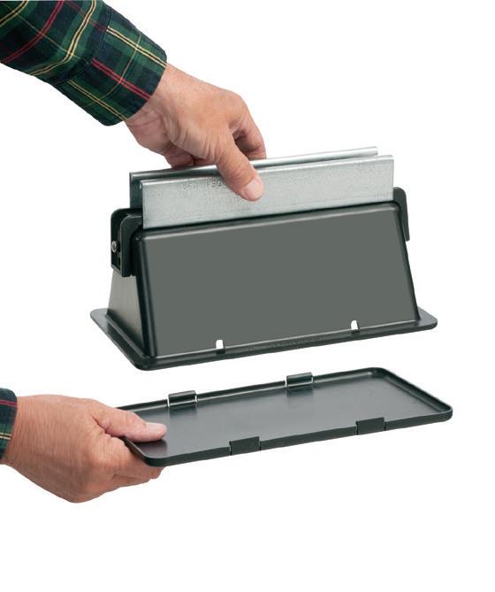
Plastic & Steel 8X10 TV BOX
Arlington’s 8X10 TV Box™ with a Plastic or Steel Box offers the ultimate in versatility for installing TVs in new and retrofit projects. There's more room in the box for wires and it installs horizontally or vertically to properly position low voltage connections behind the TV.
• Ideal for home theater systems: multiple connections for sound systems, satellite TV, CATV, DVRs
• Brackets for neater cables, with a 1-1/2" knockout for ENT and other low voltage wiring
• Box mounts to stud in new work; for retrofit, mounting wing screws secure
Arlington’s new one-piece RETROFIT SNAP2IT® fittings are easy to use in an OLD WORK installation, and handle the widest variety of cables! They’re ideal for adding additional circuits to a load center. And you get the same labor-savings in a retrofit installation!
Easy snap-in installation - NO TOOLS. Install connector into the knockout in an existing box, pulling cable/conduit through the knockout. Slip the fitting onto the cable, then snap the assembly into the box. That’s it... a secure installation with no pullout
Widest total cable ranges 14/2 to 10/3
Widest variety of cables AC, MC, HCF, MC continuous corrugated aluminum cable, MCI-A cables (steel and aluminum), AC90,
A laboratory space with minimal access to daylight may be a good candidate for active circadian entrainment lighting.
Cultivating Healthier Spaces Through Lighting Design
How designers are using breakthroughs in biologically effective lighting to mimic natural light cycles and improve human health at home and at work
By Grant Kightlinger and Lauri Tredinnick, Pivotal Lighting Design of Affiliated Engineers, Inc.
Lighting is crucial in designing and operating a healthy building because it can directly impact our health and well-being. On average, we spend about 90% of our time indoors — separated from the natural day/night cycle that regulates our physiological and psychological responses. Insufficient or poor-quality light during the day or excessive light at night can disrupt our bodies’ natural cycles and may negatively impact
our alertness, mental state, and metabolic health.
Circadian lighting — and biologically effective lighting more broadly — is an exciting frontier in the design industry with immense potential to improve occupants’ quality of life. These strategies focus on creating lighting conditions that harmonize with our biological clock, improve alertness, and support hormonal balance. Research on light’s physiological and behavioral effects is growing with various studies
demonstrating the benefits of circadianeffective lighting.
While there is substantial interest in adopting circadian-focused lighting strategies, cost and control system integration are common obstacles to implementation. Using practical approaches, designers can balance innovative circadian-effective lighting principles and real-world project requirements, achieving aesthetic and functional design objectives within budget constraints.
MC CABLE FITTINGS
each fitting also comes with end stop bushings that accommodate different size cable bundles. ONE trade size fits SEVERAL cable types and sizes, plus flexible metal conduit for super convenience and cost-savings! Reduces inventory and material handling too.
Refer to spec sheet for specific end stop sizes Listed for FMC
The circadian rhythm refers to the natural physical, mental, and behavioral changes that the body experiences during a 24-hour cycle. Light is the primary environmental cue for the human circadian system. The presence of light during the day and the absence of light at night are how the body synchronizes its internal clock with the outside world. Without light cues, the circadian system can fall out of sync. Too much light at night or insufficient light during the day can result in less restful sleep and disruption of the body’s natural cycles.
The primary factors that inform circadian-effective lighting design include:
• Spectrum. Understanding how the body responds to different wavelengths of light is essential for engineering appropriate lighting solutions. The human eye visually perceives wavelengths from about 380 to 750 nanometers (nm). The circadian system is maximally sensitive to short-wavelength (“blue”) light with a peak sensitivity of around 480 nm. Light sources that include this wavelength will most effectively stimulate the circadian system.
• Timing. Exposure to bright light from morning through midday is optimal for suppressing melatonin and synchronizing our circadian rhythm. Avoiding bright light at night is necessary to allow for melatonin production in preparation for sleep.
• Duration. The body needs an appropriate duration of light exposure to impact circadian rhythms. A 2015 study published in Sleep Medicine, for example, found that 30 minutes of bright light exposure in the morning was effective in regulating the circadian system, though longer exposures produced more robust results. At night, even brief exposure to bright light results in the suppression of melatonin and increased alertness.
• Distribution: Illumination of the vertical plane at eye level is most relevant for circadian stimulation, as opposed to light on the horizontal task plane, which is more traditionally calculated for architectural lighting design.
• Intensity: Intensity refers to the amount of circadian-effective light entering the eye and is measured using new metrics developed for this purpose.
CIRCADIAN-EFFECTIVE LIGHTING STRATEGIES
Designers selectively control the factors described above to develop a lighting strategy that supports the body’s alignment to a healthy day/night cycle. At a basic level, there are two overarching approaches for a circadian-effective lighting system: avoiding disruption and active entrainment.
• Avoiding disruption. This is an approach where the designer is not attempting to fully stimulate the circadian system using electric light, but instead designing the space to ensure that electric light does not disrupt an occupant’s existing healthy circadian cycle. The designer is careful not to introduce sources of stimulation in the evening and only uses light sources with minimal energy in the circadian sensitivity zone when night lighting is required. This approach should be the base design for nearly all spaces regularly occupied at night. It may also be appropriate in short-term occupancy spaces, assuming that effective circadian stimulation will be provided elsewhere.
Avoiding disruption is typically the most cost-effective circadian lighting
approach because it does not necessarily add any cost to the lighting or control system. It generally requires only that the designer select and locate light sources within the space to limit occupants’ exposure to short-wavelength light.
• Active entrainment . Active entrainment, in contrast, is an approach where electric lighting is designed to replace daylight as the primary stimulator of the circadian system. This typically requires higher light levels than needed for visual tasks and careful placement of light sources to ensure light reaches the occupants’ eyes. If spaces are occupied at night, a separate “night mode” should be established to prevent sleep cycle disruption, which may require more complex controls and additional or specialty luminaires.
This approach is most appropriate for environments where occupants have little or no exposure to daylight and situations involving long-term occupancy. Active entrainment is often appropriate in health care applications, such as longterm patient rooms, senior living spaces, and behavioral health spaces. Occupants
A neonatal intensive care unit with a fully indirect circadian lighting system was designed to minimize glare.
Copyright Ryan Kurtz Photography, LLC
GROUNDING BRIDGE
MULTIPLE ZINC
Arlington’s heavy-duty Grounding Bridges provide reliable intersystem bonding between power and communication grounding systems. And handle multiple hookups of communications systems: telephone, CATV and satellite.
Our new GB5T is THREADED for threaded conduit or another GB5T – with a SET SCREW for use on EMT or PVC.
Arlington’s zinc and bronze grounding bridges...
• Four termination points; more than required by the NEC
use these spaces for most of their day and may be unable to access daylight due to limited mobility or ability.
Active entrainment systems vary widely. They can range from fully custom luminaires and control software for regulation of timing and spectrum to off-the-shelf luminaires with straightforward controls for spaces where occupants are only present during the day. With careful design, most spaces can achieve active entrainment without overly complex controls. In spaces that are only occupied during the day or night, minimal control is required because the lighting needs within the space remain constant.
UNDERSTANDING THE SPACE AND OCCUPANTS
Whether pursuing an active entrainment approach or avoiding disruption, having comprehensive information about the space and how occupants behave within it is essential for a circadian-effective design. This includes awareness of:
• Occupant schedules. Understanding occupants’ schedules, including how and when they will occupy a given space, is essential. People have different lighting needs at different times throughout the day, and the optimal design requires knowledge of when and for how long people will be in the space.
• Occupant positions. Calculations are required to confirm that targets for circadian stimulus are being met based on anticipated locations of occupants within the space. For projects seeking WELL Building certification, the standard includes a circadian-effective lighting feature that sets specific calculation methods and targets.
• Vertical planes. Circadian-effective lighting focuses on the light that reaches the eye, known as vertical illuminance. When performing calculations and measurements, designers should ensure adequate light stimulus is provided at the vertical plane at the occupant’s eye level.
• Surface finishes. Understanding the different surface finishes in the space is critical, as they will determine how light is reflected within the room. Bouncing light off large, light-colored surfaces is more comfortable than
introducing light directly into the occupants’ eyes from the luminaire.
Additionally, the specific finish of a surface affects the wavelengths of light being reflected or absorbed and can significantly impact the circadian-effective light reaching the occupant.
INCORPORATING
CIRCADIAN-EFFECTIVE LIGHTING INTO PROJECTS
Circadian lighting can be a complex topic, and knowing where to start is difficult. Project goals, objectives, and constraints should be carefully considered before committing to a circadian-effective lighting strategy. Here are some key areas to consider:
• Technical requirements. Is the project seeking WELL certification? Are there other requirements that need to be met on paper?
• Circadian vs. tunable white lighting. Is the goal specifically to entrain the circadian system, or is this a project that requires color tuning as a design feature to enhance the mood or to create a dynamic environment?
• Active entrainment vs. avoiding disruption. Do occupants use the space during the day, at night, or both? Are the occupants likely to receive sufficient circadian stimulation elsewhere in their daily lives, or does the electric lighting need to provide that?
• Manual vs. programmed control . Some applications require manual control for performing visual tasks. Active circadian entrainment requires consistency to ensure the stimulation is provided at the right time of day. If the lighting schedule is regularly overridden, the controls can become more complex to accommodate. Consider using different sources of light for occupant-controllable functions versus automatic time-ofday functions.
• Extent of application. Not all spaces have the same needs. Where is circadian-effective lighting most useful and needed? Strategically limiting the scope of the application can sometimes be the only way to achieve the project goals.
• Daylight availability. Consider whether the spaces in question have daylight availability. If so, is circadian stimulation needed? Even if ample
daylight is available through windows, the designer should evaluate the spec tral transmission properties of glazing to ensure that enough light of the right wavelength reaches the eyes of the occupants.
• Project team capabilities. Who will design the system, program the con trols, and maintain it over its life? Build a team of individuals who are invested in and knowledgeable about the light ing system’s function and capabilities. A neglected and non-functional circadian lighting system can cause more prob lems than it solves.
• Budgetary constraints about the budget for circadian-effective lighting strategies and communicate pri orities up front. Where do you get the most bang for your buck? Thoughtful design doesn’t cost extra and, in some cases, is all that is needed.
LOOKING TOWARD THE FUTURE
The ongoing exploration of light’s effects on health is paving the way for significant advancements in bio logically effective lighting design. Innovations such as simplified con trols, adjustable spectrum luminaires, and artificial daylight solutions can help create environments that not only meet aesthetic and functional needs but also enhance well-being. As we continue to refine our approaches, the potential for cost-effective cir cadian lighting solutions that align with our biological rhythms becomes increasingly feasible, ultimately fos tering healthier living and working environments.
For more in-depth information, refer to the Illuminating Engineering Society’s ANSI/IES RP-46-23 – Recommended Practice: Supporting the Physiological and Behavioral Effects of Lighting in Interior Daytime Environments.
Grant Kightlinger, CLD, IALD, IES is a senior lighting designer at Pivotal Lighting Design with more than 15 years in the AEC industry.
Lauri Tredinnick, IALD, LC, LEED AP is the studio leader for Pivotal Lighting Design with more than three decades in the AEC industry.
17SAVE seconds
Fully assembled, SNAP2IT® fittings handle the widest variety of MC cable AND THE NEW MC-PCS cables.
Compared to fittings with a locknut and screw, you can’t beat these snap in connectors for time-savings!
LISTED SNAP2IT ® CONNECTORS FOR NEW MC-PCS CABLE ...lighting & low voltage circuits in the same cable
• Fits widest range and variety of MC cable 14/2 to 3/3
AC, MC, HCF, MC continuous corrugated aluminum cable and MCI-A cables (steel and aluminum)...including the new MC-PCS cable that combines power and low voltage in the same MC cable
ANY Snap2It Connectors LISTED for MC cable are also LISTED for MC-PCS cable! These products offer the greatest time-savings.
• Fast, secure snap-on installation
• Easy to remove, reusable connector From cable Loosen screw on top. Remove connector from cable. From box Slip screwdriver under notch in Snap-Tite® Remove connector.
Easy to Snap into Box!
DLC Proposes Updates on the Controls and Energy Efficiency Front
Modifications to solid-state lighting’s qualified products lists aim to streamline LED adoption with smart lighting controls, unlocking even greater energy efficiency and compatibility.
By Jason Jeunnette, DesignLights Consortium
The pace of innovation is sometimes so swift that technologies that emerged a decade or so ago are now fixtures of daily life. Take lightemitting diodes (LEDs) for example.
A January 2012 U.S. Department of Energy (DOE) report called LEDs “a new and revolutionary light source.” Then found chiefly in colored light applications, such as traffic signals and exit signs, LEDs were poised for expansion. DOE noted that white-light LEDs “have recently been commercialized” and are projected to comprise 36% of the U.S. lighting market by 2020 and 74% by 2030. However, those optimistic predictions fell short of what occurred. LEDs made up 48% of lighting installations in the United States in 2020 and became the “dominant force in the commercial lighting market,” comprising 73% of the total market share by 2024, according to a new market research report.
The impact of this market transformation has been huge, as DesignLights Consortium (DLC) Executive Director and CEO Tina Halfpenny reported to DLC members and stakeholders last year.
“Based on U.S. Department of Energy data and our team’s analysis, commercial and industrial buildings in the U.S. and Canada saved approximately 1,000 TWh of energy from 2010 to 2022 thanks to the LED revolution and our
CONCRETE PIPE SLEEVE
Arlington’s Concrete Pipe Sleeves are the economical way to sleeve through concrete pours in tilt-up construction WALLS – and FLOORS allowing cable and conduit to run easily from one floor to the next.
No costly core drilling – No cutting holes in the form. Plus, you can position the hole prior to pouring the concrete.
• Attaches to form with nails or screws
• Stackable up to 23" h for extra deep pours
• Vents keep wet pipe sleeves from sticking together
• Multiple hole sizes: 1-1/2"
Arlington’s recessed STEEL combination power/low voltage TV BOX™ is the best way to mount an LED or Hi-Def TV flush against a wall.
TV BOX provides power and/or low voltage in one or more of the openings. Plugs and connectors stay inside the box, without extending past the wall.
Designed for use in new or retrofit commercial construction where metal raceway is used, we have a STEEL TV BOX for almost any application!
• Steel box; non-metallic paintable white trim plate
• Easy, secure installation
• Optional covers
CPS40
After concrete sets, cut sleeve flush with surface. Insert conduit into sleeve.
Nail sleeve to form.
collective ability to accelerate the transition to LED lighting technology,” she wrote. “The (avoided) CO2 emissions are equivalent to approximately 1,700 gas power plants running for one year.”
These are major accomplishments, but the LED revolution isn’t over yet. With state, municipal, and private decarbonization goals pending — and the evidence of climate chaos arriving with increasing frequency — the DLC this month proposed significant updates to its technical requirements for solid-state lighting (SSL — i.e., LEDs) products as well as changes designed to streamline the pairing of lighting controls with LED luminaires (a proven energy-saving strategy).
For many years, the DLC’s technical requirements and related qualified products lists (QPLs) have formed the basis for commercial lighting rebates and incentive programs offered by three-quarters of North American electric utilities. Lighting manufacturers submit applications to add their products to the DLC’s three QPLs: SSL, networked lighting controls (NLCs), and horticultural lighting. Independent vetting determines which products are listed on the consortium’s searchable, downloadable databases. For project designers, contractors, and other lighting decision-makers, this simplifies finding high-quality, controllable, energyefficient products eligible for valuable utility incentives.
Since beginning its SSL program, the DLC has updated efficacy requirements several times, resulting in a 70% average efficacy increase for listed products since 2011. Released for stakeholder comment on April 7, its newest policy (SSL version 6.0) continues to transform the market for energy-efficient lighting products. While carefully considering what is appropriate for each product type, SSL v.6.0’s average proposed efficacy increase across all lighting categories is approximately 15% across all lighting categories, with some as high as 30%, depending on product type.
Reflective of the DLC’s mission to improve energy savings potential and the quality of light in the built environment, the new policy also correlates aspects of the SSL and NLC product lists for the first time — a change that will facilitate the selection of interoperable LED and control products. This is a vital step toward pushing the lighting market toward greater utilization of lighting controls that save energy and increase the comfort and functionality of commercial spaces.
Research shows that adding NLCs to commercial lighting upgrades can cut a project’s new lighting load in half. Integrating NLCs with building HVAC systems can yield even more savings (up to 20% of the total energy load in large commercial buildings). As the first generation of LEDs is now ready for replacement, the essential first step in realizing these potential savings is ensuring that new LED projects and upgrades either include lighting controls or are installed as “controls ready.”
While NLC penetration has expanded in the commercial lighting market over the past several years, a 2024 DOE report (based on 2020 data) revealed that about 70% of LED installations still lacked controls.
(SEE ABOVE)
• Easy snap-in cable installation Save time over 90° 2-screw MC Connectors at same cost per connector
• Handles widest range & variety of cables: 14/2 to 10/2 AC, MC, HCF, MC continuous corrugated aluminum cable, MCI-A cables (steel & aluminum), AC90 and ACG90
• Fast, secure installation...No pullout
• Easy to remove from box...reusable
40900ST
With abundant potential savings on the table, why haven’t NLCs caught on to a greater degree? From our discussions at the DLC 2024 Controls Summit last October — as well as conversations with stakeholders such as property managers — we know one roadblock to greater NLC adoption is customers’ fear of being locked into single-vendor proprietary systems.
The DLC’s proposed policy change addresses this by modifying the SSL QPL to more clearly show integral control capabilities and technologies of listed luminaires and indicate which variations of a manufacturer’s lighting products work with the control systems they also develop. This will enable contractors to confirm that a specific luminaire model number they plan to order both comes with integral controls and is eligible for NLC incentives available from their local electric utility or energy efficiency program.
In correlating its SSL and NLC-qualified product lists, the DLC plans to organize all listed products into six control categories (see Chart on page 46) based on how the luminaire is sold and shipped from the manufacturer:
1. Luminaire Only (i.e., no control capability);
2. Luminaire Only/Controls Ready (controls can be installed on site without additional wiring);
3. Luminaire With Occupancy Sensors (not networked);
4. Luminaire With Occupancy Sensor and Daylight Sensor/ Photocell (not networked);
5. Luminaire With Networked Controller; and
6. Luminaire With Networked Controller and Occupancy and Daylight Sensors (Luminaire Level Lighting Controls — LLLC).
This update will enable users of the DLC’s QPL to enter a complete LED luminaire model number into the search engine and — assuming the luminaire is listed — receive a result that indicates the product is DLC listed and what the control options are for that specific model number. This saves time and eliminates confusion for project designers and contractors while paving the way for quicker, easier integration of LED installations with energy-saving, smart building-enhancing controls.
The first major revision of DLC technical requirements governing commercial LED luminaires since 2020, SSL v6.0 includes several other important updates as well. Among these are changes that strengthen its LUNA program for light pollution-mitigating outdoor lighting, introduce support for solar-powered lighting products, and provide lighting decision-makers with clearer information about the lifetime of lighting products being installed as well as their environmental impact.
Overall, the DLC believes these various policy shifts and updates will facilitate the optimal selection and installation of LED products and thereby continue to improve energy savings and quality of light in the built environment.
We look forward to feedback on SSL v6.0 during a stakeholder comment period that runs through May 19th: https:// designlights.org/our-work/solid-state-lighting/ssl-v6-0-andluna-v2-0-technical-requirements-draft-1/.
Jason Jeunnette is the DesignLights Consortium’s technical manager for building integration and controls. He can be reached at jjeunnette@designlights.org.
FLOOR BOX
(3) FLBC8500 boxes
a two-gang box. Add another for three-gang! FLBC8500 Single gang box
Single gang
FLBC8510BR Brown
FLBC8510BL Black
FLBC8510GY Gray
FLBC8510CA Caramel
FLBC8510LA Lt Almond
Two-gang
FLBC8520BR Brown
FLBC8520BL Black
FLBC8520GY Gray
FLBC8520CA Caramel
FLBC8520LA Lt Almond
Three-gang
FLBC8530BR Brown
FLBC8530BL Black
FLBC8530GY Gray
FLBC8530CA Caramel
FLBC8530LA Lt Almond
Build a two- or three-gang concrete floor box by simply locking single gang boxes together!
Then buy the UL LISTED single, two- or three-gang cover/frame kit, with devices included, in PLASTIC, FIVE COLORS – or in economical diecast zinc with a brass or nickel finish. Fast, easy installation.
Cover installs with hinge on either side.
Two-gang FLBC8520MB
Three-gang FLBC8530MB
(1) FLBC8530BL Black plastic cover/frame kit
FLBC8530MB
A Quick Guide to Emergency Lighting and Controls
How integrated controls and LED advancements make emergency lighting smarter, more efficient, and easier to install
By Martin Mercier, P.Eng., Cooper Lighting Solutions
Imagine a bustling office building plunged into darkness. The power outage initially creates chaos and confusion, but the emergency lighting system quickly steps in to calm the situation. It’s the unsung hero, guiding people safely to exits during emergencies.
UNDERSTANDING THE BASICS
Before diving into the technicalities, let’s clarify two key terms:
• Egress lighting: This refers to the continuous illumination of escape paths during normal building operations.
• Emergency lighting: This system kicks in during power outages, providing additional illumination to complement egress lighting and illuminate exit signs. Some luminaires
can serve both purposes, while others are dedicated to emergency use.
THE REGULATORY LANDSCAPE
Designing and implementing emergency lighting systems is complex due to various safety regulations and codes. Key codes governing emergency lighting include:
• NFPA 101 (Life Safety Code): Sets standards for occupant safety in buildings.
• International Building Code (IBC): Outlines requirements for means of egress.
• NFPA 70 (National Electrical Code - NEC): Governs the safe installation of electrical wiring and equipment.
Cooper Lighting
ENTRANCE PLATES, HOODS, DEVICES NON-METALLIC
The SCOOP™ series of reversible, non-metallic ENTRANCE HOODS, PLATES AND DEVICES protect cable while delivering good looks and installation versatility. They also reduce labor and eliminate extra connections.
Our newest CABLE ENTRY DEVICES come with or without a wall plate for efficient cable management. HOODS for decorator-style wall plates, single and two-gang PLATES install facing in or out...and save time!
• Low voltage cable protection
• Best way to run cable
• Underwriters Laboratories (UL) safety standards: Define the performance standards for emergency lighting products.
BALANCING NORMAL AND EMERGENCY OPERATIONS
NFPA codes differentiate between normal building operations and emergencies. During normal operations, a minimum of 1 foot-candle (fc) of illumination is required along escape paths. However, during emergencies, the requirements are stricter:
• Rapid activation: Emergency lighting must activate within 10 seconds of power loss.
• Duration: It must remain illuminated for at least 90 minutes.
• Illumination level: A minimum average of 1 fc is required with a minimum of 0.1 fc.
CONTROLLING THE LIGHTS: A DELICATE BALANCE
To ensure optimal performance, continuous egress lighting can be provided by general luminaires strategically placed along escape paths. However, NFPA 101 allows for turning off these luminaires under certain conditions, including:
• Listed control devices: The control device must be UL-listed.
• Automatic emergency power activation: The system must automatically switch to emergency power upon power loss.
• Illumination timers: Timers should have a minimum 15-minute delay.
• Occupancy sensor activation: The system should activate based on occupant movement.
• Fire alarm integration: The system can be integrated with the building’s fire alarm system.
• Exclusions: The control system should not affect photoluminescent exit signs, battery-equipped emergency luminaires, or other critical lighting elements.
NAVIGATING ENERGY CODES
Commercial building energy codes often require automatic shutoff for lighting when not in use. However, exceptions
exist for emergency and egress lighting. For instance, the International Energy Conservation Code (IECC) and California’s Title 24 allow specific lighting loads to remain on for egress purposes.
CHOOSING THE RIGHT LIGHTING SOLUTION
When selecting emergency lighting solutions, consider the following options:
• Building power generator and inverters — Including single-phase mini-inverter systems designed to provide emergency power for lighting applications.
• General luminaires with EM drivers/ballasts — With a battery pack, luminaires can serve normal and emergency lighting functions, eliminating the need for separate emergency power sources.
• General luminaires with connected lighting and EM capabilities — Recently wired and wireless control systems provide reliable emergency lighting control without additional wiring or emergency transfer devices.
THE FUTURE OF EMERGENCY LIGHTING
With advancements in LED technology and control systems, emergency lighting is becoming more integrated with overall building automation systems. This integration offers greater flexibility, efficiency, and enhanced safety. By understanding the complexities of emergency lighting and adhering to relevant codes and standards, building owners and designers can ensure the safety of occupants during power outages and other emergencies.
Mercier, P.Eng., is strategic marketing manager for IoT and connected systems for Cooper Lighting Solutions, a division of Signify (formerly known as Philips Lighting), based in Peachtree City, Ga. Previously, he was a senior product manager for advanced lighting technology systems for the Americas for eight years with Signify.
Advancements in lighting and control technology have enabled emergency lighting to become more integrated with overall building automation systems, such as those used in school settings.
Arlington’s steel SliderBar™ offers the easy, NEAT way to mount single or two-gang boxes between wood or metal studs with non-standard stud cavities.
No more cutting, nailing and fitting extra 2x4s to fill the space! SliderBar saves about 20 minutes per box. Designed for studs spaced 12” to 18” apart, SL18 allows positioning of one or more boxes anywhere in the stud cavity.
• Bending guides on bracket assure proper positioning on studs
• Pre-punched pilot holes on BOTH sides of S for easy attachment of one or two boxes
Servicing Equipment in Challenging Locations
An analysis of the unique role luminaires play in
reducing unplanned downtime
By Tim Stevens, Kenall Manufacturing
Construction projects within the technology and health care sectors often require changes in architecture that support delicate and sensitive work. While this cleanroom-like construction method is not new, it is expanding. For instance, according to Deloitte, in most modern hospitals, there are at least a dozen cleanrooms. Many industrial spaces have also adopted cleanroom designs. The sectors aim to increase the quality of a product, improve outcomes for patients, reduce contamination, and/or maintain a sterile field. When cleanliness is the goal, it must start at the top.
The ceiling is — and always has been — the source of air. However, it is now common to also use the ceiling to support technical equipment. Think of a surgical suite where devices previously on rolling carts are now attached to the ceiling (Photo 1). Since some processes critical to the space are happening above the ceiling — an area we call the plenum — many new reasons now exist to enter the plenum.
Historically, servicing this equipment relied on simple, lay-in grid ceilings. However, those days are gone. These clean environments now require sealed, locked-down panels or solid ceilings, according to Chapter 3, “The Role of Technology in the Connected Ecosystem,” of the FDA Food Safety Modernization Act. To the building owner, facility manager, and construction team, these changes mean that once
1. Surgical suite ceilings are complicated with many luminaires and filters — all needing space. However, plenum-access luminaires allow access to the equipment above the plenum by providing a panel or opening within the unit.
the ceiling is in place, free access to the area above the ceiling no longer exists (Photo 2 on page 56).
Often, a dedicated access panel is installed in the ceiling to allow access to the plenum space. However, each opening creates a potential source of contamination as well as an additional cost. These ceilings are often complicated, with luminaires and filters both requiring space in the ceiling. Often, a
single access panel is insufficient. Additionally, sending someone to crawl into the space risks violating OSHA’s Confined Spaces safety rules, CFR 1910.146.
To meet this challenge, forwardthinking lighting manufacturers have created plenum-access luminaires that provide access to the equipment above the ceiling via a sealed, removable panel within the luminaire itself (Photo 3 on page 56). This design helps simplify the ceiling layout, prevents the disruption caused by removing a luminaire, and permits the room’s quick return to full function.
Photo
REDUCING PLANT DOWNTIME
Each year, millions of dollars of capital improvements are made to facilities and equipment to increase product safety, protect employees, and reduce costs. This is a critical expenditure because equipment in a typical food processing plant often runs 16 to 24 hours per day, seven days per week. Equipment failure is the most common cause of plant downtime. The longer it takes plant personnel to respond to and repair equipment, the more damaging the interruption to the business. As such, systems that are not operating at maximum speed create a domino effect that can result in missed deadlines, lost revenue, and disappointed customers.
According to Deloitte, poor maintenance strategies can reduce a facility’s overall productive capacity by 5% to 20%. Recent studies also show that unplanned downtime is costing industrial manufacturers an estimated $50 billion each year, according to the article, “Predictive Maintenance and the Smart Factory.” For maintenance and facility managers, the mere utterance of the words “unplanned downtime” often elicits panic. To compensate for this, facility managers and company leadership must find innovative ways to solve the root cause of such problems.
SEALED LUMINAIRES
The need is greater than ever to optimize equipment reliability to maximize uptime and productivity. According to a 2018 McKinsey & Company report, “Customers are demanding machines that improve operational efficiency, cut costs, and increase uptimes…”
While plant managers are typically focused on line production equipment, food processing companies can help reduce food-borne illnesses, and lessen operating costs and unplanned downtime through the use of sealed luminaires. Innovative infrastructure solutions like sealed LED luminaires can ensure sanitation regulations are met, and maintenance above production lines is minimized, which reduces downtime and addresses this pressing challenge.
A well-designed sealed enclosure, utilizing high-quality construction and materials, virtually eliminates the risk of contamination and the need for frequent maintenance. Taking it a step further, luminaires with a nonporous, sealed design ensure they remain free of corrosion, dust, dirt, insects, moisture, and bacteria. This sealed luminaire design also helps reduce costly unscheduled maintenance and downtime by protecting the luminaire’s internal components.
PLANT ILLUMINATION AND STANDARDS
Due to related health and wellness concerns, food processing plants must pay close attention to food safety. Typically, this involves power washing and sanitizing equipment. Food manufacturing facilities must follow many stringent USDA regulations, including those involving the presence of glass in the facility. When handled incorrectly, glass, such as that in some luminaires, poses the threat of contamination. Specifically, the Food and Drug Administration (FDA) requires that sealed enclosure luminaires be certified to Ingress Protection (IP) and National Sanitation Foundation (NSF) standards to reduce the risk of
contamination and avoid costly disruption of work due to unscheduled maintenance.
The purpose of the food equipment standard is to establish minimum food protection and sanitation requirements for the materials, design, fabrication, construction, and performance of food handling and processing equipment, including luminaires. To ensure safety and reduce maintenance, the FDA has developed certifications and standards. For example, relative to lighting in the food processing plant, the light should be:
• Easy to clean.
• Made of smooth, hole-free, and corrosion-resistant material.
• Designed to reduce the ingress of dust, debris, pests, and other possible hazards.
In addition to the food equipment standard, color rendering guidelines have been established to help ensure proper product examination during quality inspections. Food processing environments are also required to have the correct amount of illumination at each task location. To comply with the stringent standards set by the USDA, FDA, and Illuminating Engineering Society (IES), a minimum color rendering index of 85 is recommended in instances where color rendering is critical.
MAINTAINING SANITATION
The Food Safety Modernization Act has transformed the nation’s food safety system by shifting the focus from
responding to foodborne illness to preventing it. Product recalls cost food and beverage companies millions of dollars each year, but 56% of 2019’s recalls across the United States, United Kingdom, and Ireland were preventable, according to the FDA Food Safety Modernization Act. Processors must commit to improving equipment hygiene. However, keeping equipment clean presents challenges, which manufacturers can help overcome.
Food processing plants are a very difficult environment for luminaires to endure due to the daily cleaning and sanitizing. Harsh chemicals like sodium hydroxide and other caustics are used to clean equipment and can be extremely corrosive to luminaire housings. In addition to caustic chemicals, high-pressure water spray is used — sometimes up to 1,000 psi. While this ensures all contaminants are removed, unsealed luminaires allow the ingress of water, causing extensive damage.
Sealed enclosure luminaires, however, prevent both the ingress and egress of dust, fungus, bacteria, and other contaminants that might put processes and people at risk. Additionally, NSF P442 requires stringent pressure testing and third-party certification to prove that luminaires are qualified for clean industrial applications: They must prevent the
Forward-thinking
manufacturers have designed and engineered plenum-access
allow access to the equipment in the ceiling by providing a panel or opening within the unit itself. This engineering simplifies ceiling layout, prevents the disruption caused by removing a luminaire, and permits a quick return to full function.
flow of air between the plenum space and the controlled environment, be protected from contaminants, particulates, and moisture, and be easily cleanable. This protocol is very difficult to achieve but
proves that a luminaire is truly leak-proof and ready for use in the most challenging environments. Not every situation demands this protocol — for those that do, look for the NSF P442 certification.
INNOVATION MITIGATES CHALLENGES
To meet industry requirements, reduce unplanned downtime, and improve operational efficiencies — whether that’s in a health care or processing plant setting — facility managers need to consider innovative technology. As electrical contractors, it’s critical to know the latest and most advantageous technologies available because you play a unique role when servicing challenging projects, as an unbiased, honest broker working in your client’s best interest. Providing invaluable counsel regarding the most effective lighting solution to address unique project challenges positions you as a trusted, collaborative, and well-respected partner.
Tim Stevens is a senior product manager with Kenall Manufacturing and may be reached at timothy.stevens@kenall.com.
Ivan
Photo 3.
lighting
luminaires that
Kenall Manufacturing
Photo 2. The ceiling plenum serves as a hidden space where various mechanical systems, such as electrical wiring, plumbing pipes, and network cabling, reside. Accessing this equipment while adhering to industry regulations is challenging.
WHERE FACILITY CHALLENGES FIND SOLUTIONS
NORTHWEST
May 14-15, 2025
Oregon Convention Center Portland, OR
RENO
August 20-21, 2025
Grand Sierra Resort & Casino Reno, NV
CODE BASICS
NEC Requirements for Conductors
Correctly implementing conductor requirements involves more than just looking something up in a table.
By Mike Holt, NEC Consultant
Article 310 contains the general requirements for conductors, such as their insulation markings, ampacity ratings, and conditions of use. It does not apply to conductors that are part of flexible cords or fixture wires, or to those that are an integral part of equipment [Sec. 90.7 and Sec. 300.1(B)].
The minimum sizes of conductors are 14 AWG copper or 12 AWG aluminum or copper-clad aluminum, except as permitted elsewhere in the Code [Sec. 310.3(A)]. For example, you can install conductors smaller than 14 AWG for Class 1 powerlimited circuits [Sec. 724.43], fixture wire [Sec. 402.6], and motor control circuits [Table 430.72(B)(2)].
Conductors must be copper, aluminum, or copper-clad aluminum. Aluminum and copper-clad aluminum conductors must comply with Sec. 310.3(B)(1) through (4). For example, stranded aluminum conductors must be made of an AA-8000 series electrical-grade aluminum alloy.
Conductors 8 AWG and larger installed in a raceway must be stranded, unless specifically permitted or required elsewhere in the Code to be solid [Sec. 310.3(C)]. Conductors must be insulated, unless specifically permitted to be bare [Sec. 310.3(D)].
Table 310.4(1) provides information on conductor insulation properties such as letter type, maximum operating
temperature, application, insulation, and outer cover properties (Fig. 1).
CONDUCTOR IDENTIFICATION
• Insulated neutral conductors must be identified white or gray per Sec. 200.6 [Sec. 310.6(A)].
• Insulated equipment grounding conductors must be identified green or green with yellow stripe per Sec. 250.119 [Sec. 310.6(B)].
• Phase conductor insulation can be any color but white [Sec. 200.6] or green [Sec. 250.119] [Sec. 310.6(C)].
Where premises wiring is supplied from more than one nominal voltage system, branch-circuit phase conductors must be identified per Sec. 210.5(C), and feeders must be identified per Sec. 215.12(C).
USES PERMITTED
Conductors described in Table 310.4(1) are permitted for use in any of the wiring methods covered in Chapter 3 and as specified in their respective tables or as permitted elsewhere in the Code. Some specifics are listed in Sec. 310.10(A) through (G). For example, conductors exposed to oils, greases, vapors, gases, fumes, liquids, or other substances (having a harmful effect on the conductor or insulation) must be a type suitable for the application [Sec. 310.10(F)].
About half of Sec. 310.10 consists of (G), which addresses conductors in parallel. Among the requirements are that the conductors must be of the same length, have the same conductor material, have the same type of insulation, and terminate in the same manner.
Fig. 1. Information on conductor insulation properties are found in Table 310.4(1).
DWELLING SERVICES AND FEEDERS
Dwelling unit services and feeders can be sized per the following:
(A) Services. Service conductors supplying the entire load associated with a one-family dwelling unit can be sized per Table 310.12(A) where there is no conductor ampacity adjustment or correction as required by Sec. 310.15 [Sec. 310.12(A)]. Table 310.12(A) cannot be used to size service conductors for twofamily or multifamily dwelling buildings (Fig. 2).
(B) Feeders. Feeder conductors supplying the entire load associated with a one-family dwelling or an individual dwelling unit in a two-family or multifamily dwelling can be sized per Table 310.12(A).
(C) Feeder Conductors. Not Greater Than Service Conductors. The feeder conductor ampacity for an individual dwelling unit is not required to be larger than the service conductor.
(D) Neutral Conductors. Neutral conductors can be sized smaller than the phase conductors if the requirements of Sec. 220.61 and Sec. 230.42(C) for service conductors, or the requirements of Sec. 215.2(A)(2) and Sec. 220.61 for feeder conductors are met.
AMPACITIES FOR CONDUCTORS
RATED UP TO 2,000V
“Ampacity” is equal to the maximum current (in amperes) a conductor can carry continuously under its conditions of use without exceeding its temperature rating [Art. 100]. The ampacity of a conductor can be determined either by using the tables in the NEC as corrected and adjusted per Sec. 310.15, or under engineering supervision as provided in Sec. 310.14(B) [Sec. 310.14(A)(1)].
Where more than one ampacity applies to part of the circuit because of temperature correction [Table 310.15(B) (1)(1)] or adjustment factors [Table 310.15(C)(1)], the lowest ampacity value must be used for the total circuit.
Exception: When different ampacities apply to parts of a circuit because of temperature correction [Table 310.15(B) (1)(1)] or adjustment factors [Table 310.15(C)(1)], the higher ampacity can
Fig. 2. Table 310.12(A) cannot be used to size service conductors for two-family or multifamily dwelling buildings.
apply for the entire circuit if the length of the lower ampacity does not exceed the lesser of 10 ft or 10 percent of the total circuit’s length.
“Ampacity” is equal to the maximum current (in amperes) a conductor can carry continuously under its conditions of use without exceeding its temperature rating.
Conductors cannot be used where the operating temperature exceeds that designated for the type of insulated conductor involved [Sec. 310.14(A)(3)].
The insulation temperature rating of Table 310.4(1) insulated conductors is the maximum temperature a conductor can withstand over a prolonged period
without serious degradation. The main factors to consider for conductor operating temperature are:
• Ambient temperature that may vary along the conductor length, plus from time to time [Table 310.15(B)(1)(1)].
• Heat generated internally in the conductor as a result of the load current flow.
• The rate at which heat dissipates into the ambient medium.
• Adjacent load-carrying conductors that have the effect of raising the ambient temperature and impeding heat dissipation [Table 310.15(C)(1)].
The insulation temperature rating of a conductor must be limited to an operating temperature that prevents damage to the conductor’s insulation. If the conductor carries excessive current, the I2R heating within the conductor can destroy its insulation. For this reason, elevated conductor operating temperatures created by current flow within conductors and conductor bundling might need to be limited.
AMPACITY TABLES
The temperature ampacity correction [Sec. 310.15(B)(1)] and adjustment ampacity factors [Sec. 310.15(C)(1)] are applied to the ampacities listed in Table 310.16, based on the conductor’s insulation temperature rating.
CODE BASICS
The Table 310.16 ampacity must be corrected when the ambient temperature is not between 78°F and 86°F, and must be adjusted when more than three current-carrying conductors are bundled. The temperature correction multiplier [Sec. 310.15(B)(1)] and adjustment multiplier [Sec. 310.15(C)(1)] are applied to the conductor ampacity based on the temperature rating of the conductor insulation (not the temperature rating of the terminal) as contained in Table 310.16 (typically in the 90°C column), as shown in Fig. 3. However, the corrected or adjusted conductor ampacity must not exceed the temperature rating of the equipment terminations of Sec. 110.14(C).
The neutral conductor might be a current-carrying conductor, but only under the conditions specified in Sec. 310.15(E). Equipment grounding conductors are never considered current-carrying [Sec. 310.15(F)].
Where raceways or cables are exposed to direct sunlight and located less than 3/4 in. above the roof, a temperature of 60°F (33°C) must be added to the outdoor ambient temperature to determine the ambient temperature correction per Table 310.15(B)(1)(1).
AMPACITY ADJUSTMENT
Where four or more current-carrying conductors are in a raceway or cable, the conductor ampacities in Table 310.16 in the 90°C column must be adjusted per Table 310.15(C)(1).
Where cables are bundled without maintaining spacing for more than 24 in., the conductor ampacities contained in Table 310.16 in the 90°C column must be adjusted per Table 310.15(C)(1).
The conductor ampacity adjustment of Table 310.15(C)(1) does not apply to conductors in Type AC or Type MC cable under all of the four conditions listed in Sec. 310.15(C)(1)(d). For example, the cables do not have an outer jacket.
The neutral conductor of a 3-wire, single-phase, 120V/240V system, or a 4-wire, three-phase, 120V/208V or 277V/480V wye-connected system, supplying linear loads is not considered a current-carrying conductor for the application of conductor ampacity adjustments per Table 310.15(C)(1) [Sec. 310.15(E)(1)].
Fig. 3. The temperature correction multiplier and adjustment multiplier are applied to the conductor ampacity based on the temperature rating of the conductor insulation as contained in Table 310.16.
The neutral conductor of a 3-wire circuit from a 4-wire, 3-phase, wyeconnected system is considered a current-carrying conductor for conductor ampacity adjustments per Table 310.15(C)(1) [Sec. 310.15(E)(2)].
Correcting conductor-related violations can be expensive, due not only to the sheer work involved but also due to project completion delays.
On a 4-wire, 3-phase, wye circuit where the major portion of the load consists of nonlinear loads, the neutral conductor is considered a current-carrying conductor for conductor ampacity adjustments per Table 310.15(C)(1) [Sec. 310.15(E)(3].
Equipment grounding and bonding conductors are not considered
current-carrying for conductor ampacity adjustments per Table 310.15(C)(1) [Sec. 310.15(F)].
The ampacities of conductors in raceways, in cables, or directly buried (specified in Table 310.16) are based on the four conditions listed in Sec. 310.16. For example, there are not more than three current-carrying conductors.
VIOLATION PREVENTION
Correcting conductor-related violations can be expensive, due not only to the sheer work involved but also due to project completion delays. Most errors are due to incorrect use of the tables. Check the table heading to ensure you have the correct table, and carefully read the table notes.
Always choose the temperature column that matches the rating of the insulation of the particular conductor in question and doesn’t exceed the temperature rating of the equipment terminations. If you have a 90° conductor and a 60° termination, you must use the 60° column.
These materials are provided by Mike Holt Enterprises in Leesburg, Fla. To view Code training materials offered by this company, visit www.mikeholt.com/code.
CODE QUIZ OF THE MONTH
Test Your Code IQ
How much do you know about the National Electrical Code?
By Mike Holt, NEC Consultant
All questions and answers are based on the 2023 NEC.
Q1: Underground shall be installed so they are accessible without excavating sidewalks, paving, earth, or other substance that is to be used to establish the finished grade.
a) boxes and handhole enclosures
b) conduit bodies
c) handhole enclosures
d) none of these
Q2: When nongrounding-type receptacles are replaced by GFCI-type receptacles where attachment to an equipment grounding conductor does not exist in the receptacle enclosure, shall be marked “No Equipment Ground.”
a) the receptacle
b) the protective device
c) the branch circuit
d) these receptacles or their cover plates
Q3: Unused openings for circuit breakers and switches in switchboards and panelboards shall be closed using , or other approved means that provide protection substantially equivalent to the wall of the enclosure.
a) duct seal and tape
b) identified closures
c) exothermic welding
d) sheet metal
Q4: Where a branch circuit supplies continuous loads and/or noncontinuous loads, the rating of the overcurrent device shall not be less than the noncontinuous load plus of the continuous load.
a) 80% c) 120%
b) 115% d) 125%
Q5: Where conduit or tubing is used for the protection from physical damage of Type NM cable, it shall be provided
with a bushing or adapter that protects from abrasion at the point where the cable the raceway.
a) enters and exits
b) leaves and comes into
c) begins and ends
d) none of these
Q6: Power-supply cords, communications cables, connecting cables, interconnecting cables, and associated boxes, connectors, plugs, and receptacles that are listed as part of, or for, information technology equipment shall not be required to be secured in place where installed
a) above suspended ceilings
b) exposed on interior walls
c) under raised floors
d) exposed on exterior walls
See the answers to these Code questions online at ecmweb.com/55270870.
PRACTICALLY SPEAKING
Breaking Down Communications Outlet Requirements
A close examination of NEC requirements for communication outlets
By Russ LeBlanc, NEC Consultant
Before 2008, communications outlets were not required to be installed in dwelling units. However, a proposal was submitted for the 2008 Code to require a minimum of two communications outlets for newly constructed dwelling units. NEC Code Making Panel 16 accepted this proposal in principle with new Sec. 800.156. It stated: “For new construction, a minimum of one communications outlet shall be installed within the dwelling and cabled to the service provider demarcation point.”
Part of the substantiation for this revision included the ability of the dwelling unit occupants to be able to make a simple call to emergency services such as police, fire, ambulance, or rescue squad. It is certainly hard to argue against that logic, but keep in mind that this proposal was submitted before smart phones became mainstream. The iPhone was released in 2007 and Android phones in 2008. This new cell phone technology revolutionized the way we communicate, and landlines started to be needed less and less. The 2011 Code was revised to require the communications outlet to be installed in a “readily accessible area.” For 2023, the requirement for a communications outlet is the same as it was in 2011, with the only difference being a change in the Code section from Sec. 800.156 to the newly created Sec. 805.156.
Now, here comes the weird part. Nobody knows what a “communications outlet” is. I could tell you what I
think it is, but I would just be making up stuff. There is no definition for “communications outlet” in the Code. There isn’t one now, and there never has been. So, what is a “communications outlet”? A phone jack? A Cat. 6 port? A CATV connection? A local antenna connection? None of these? Any of these? Could a communications outlet be a 125V, 15A receptacle with powerline communications modems plugged in? Honestly, your guess is as good as mine. The literal wording in Sec. 805.156 requires cables to be installed to the service provider demarcation point. How do we
satisfy this requirement if the dwelling is located where there are no communications service providers such as in a remote location high in the mountains or deep in the woods? Between cell phones, satellite phones, power line communication, and other wireless technologies, perhaps it may be time to revisit this requirement to see if it is still relevant for today and going forward. In the meantime, I’ll be using my iPhone to make phone calls, send text messages, pay bills, and stream movies directly to my smart TV without any hardwired communications circuits.
CODE VIOLATIONS
Illustrated Catastrophes
By Russ LeBlanc, NEC Consultant
All references are based on the 2023 edition of the NEC.
PARKING LOT POLE PROBLEMS
A big “thank you” goes to Daniel K., an electrical engineer from Boston, for sharing this photo with us. In Daniel’s words, he found this “public electrocution shock hazard” at a parking lot pole light for a shopping plaza.
I agree with Daniel that the missing cover increases the risk of getting shocked by the exposed energized wires. An unsuspecting person (including a child) could easily stick their fingers in that handhole and make contact with the energized wires and connections. Section 410.30(B)(1) requires the handhole on this metal pole to have a cover suitable for use in wet locations to prevent people from inadvertently touching the energized wires and to protect the wires from environmental hazards such as sunlight, rain, snow, and even critters who may want to climb inside that pole and start chewing. Apparently, the last person to work on the pole could not find a handhole cover so they haphazardly wrapped some black electrical tape around the pole in a half-hearted attempt to keep the wires inside the pole. If the tape was meant to be a “temporary fix” until the real cover was installed, I suppose the installer should have used a lot more tape.
SCARY FOUNTAIN WIRING
This is definitely one of the most dangerous installations I have ever discovered. This fountain is located in the lobby of a resort hotel and is fully
accessible to the general public. Children can sit right on the edge of this fountain and grab those exposed wires. That is really scary to me.
The combination of the missing cover and wires dangling directly in the water creates a tremendous shock hazard. The wires were used to power some 120V floodlights installed to light up the fountain. The missing box cover violates Sec. 314.25. The lack of a raceway for the black and white wires is a violation of Sec. 310.10. The lack of any equipment grounding conductor violates many requirements, including Secs. 250.112, 410.42, 680.7, and 680.54.
I was only visiting this hotel as a guest and was not able to determine if this circuit has GFCI protection. I certainly hope it does. However, seeing how the rest of this installation was made, I tend to doubt it. While GFCI protection can help reduce the risk of shock, it can’t prevent every type of shock. The risk of getting a shock here is very high.
ADVERTISER INDEX
To place a display ad (1/6 page or larger), call the Advertising Sales Representative for your area.
David Sevin | Account Manager 24 Houghton Street • Barrington, RI 02806 (401) 246-1903
E-mail: dsevin@endeavorb2b.com
Midwest, Southeast,and Southwest
Jay Thompson | Account Manager 7450 W. 130th Street, Suite #210
Overland Park, KS 66213 • (913) 967-7543
E-mail: jthompson@endeavorb2b.com
Marketplace/Inside Sales
Steve Suarez | Media Account Exec 7450 W. 130th Street, Suite #210 Overland Park, KS 66213 • (816) 588-7372
E-mail: ssuarez@endeavorb2b.com
CODE VIOLATIONS
By Russ LeBlanc, NEC Consultant
How well do you know the Code?
Think you can spot violations the original installer either ignored or couldn’t identify? Here’s your chance to moonlight as an electrical inspector and secondguess someone else’s work from the safety of your living room or office. Can you identify the specific Code violation(s) in this photo? Note: Submitted comments must include specific references from the 2023 NEC.
Hint: The weather forecast calls for rain.
‘TELL THEM WHAT THEY’VE WON...’
Using the 2023 NEC, correctly identify the Code violation(s) in this month’s photo — in 200 words or less — and you could win a $25 Amazon gift card. E-mail your response, including your name and mailing address, to russ@russleblanc.net, and Russ will select one winner (excluding manufacturers and prior winners) at random from the correct submissions. Note that submissions without an address will not be eligible to win.
FEBRUARY WINNER
This month’s winner is Robert Barnett with TriCounty Electric LLC of Brookville, Ohio. He knew that knockout rings cannot be used to establish the electrical continuity between the metal raceways and the metal enclosure of this disconnect when the circuit is operating over 250V to ground.
This 3-phase, 480V circuit is operating at 277V to ground. For installations like this, Sec. 250.97 requires the continuity between the metal raceways and metal cabinet to be “ensured by one or more of the methods specified for services in Sec. 250.92(B) except for (B)(1).”
Section 250.92(B)(4) specifies the use of bonding locknuts, bushings, or bonding bushings with bonding jumpers to bond around the remaining rings. Bonding bushings with bonding jumpers would be great here. Using only standard locknuts for bonding and grounding these raceways is not permitted.
Tackle Projects
Need a control that can handle more? Simplify projects without sacrificing performance with one of four new Contractor Boxes from Intermatic. Our expanded portfolio of field-ready solutions allows contractors to install a durable enclosure that houses a built-in 7-day Astronomic timer and a 3-pole, 4-pole, 8-pole, or 12-pole contactor.
These versatile, UL-listed solutions save time in the field and can support applications ranging from motor control and parking lot lighting to big box stores and university campuses. Upgrade today and install our code-compliant alternative to a la carte lighting control boxes and stackable contactors.
NO BURN-THROUGH CHAMPION DUCT® ELBOWS SOLVE UTILITIES CHALLENGES
No burn-through eliminates elbow repairs
Light weight facilitates a smooth, safe installation
Fault resistance makes repairing cables easy
Durable and corrosion-resistant for lower total cost of ownership