


With more than 750,000 parts from over a thousand brands, AutoZone is here to help you get exactly what you need, exactly how you need it. That way, you can get more bays turned, faster. And more customers on their way, happier.

12 Build and Trust Your Diagnostic Process
We’ve all encountered that vehicle that comes from another shop. The one where it seemed every time the right decision could have been made, the technician turned left.
Chris Martino
18 Tire Match Mounting
Optimizing tire/wheel imbalance and radial runout.
Mike Mavrigian
26 Electric A/C Compressors
Prompted by HEVs, PHEVs and electric vehicles, the use of electric compressors offers distinct advantages.
Jeff Taylor
35 The Cranky Ford
Many times driveability symptoms surface without associated DTCs. I find working backwards from the symptoms serves me best.
Brandon Steckler
40 EV Thermal Management
What once was known as HVAC is so much more.
Craig Van Batenburg
58 The Trainer #151
GDI Driveability: The Preliminary Approach
Brandon Steckler
negligence, accident, or any other cause whatsoever. The views and opinions in the articles herein are not to be taken as official expressions of the publishers, unless so stated. The publishers do not warrant either expressly or by implication, the factual accuracy of the articles herein, nor do they so warrant any views or opinions by the authors of said articles.
Endeavor Business Media provides certain customer contact data (such as customers’ names, addresses, phone numbers, and e-mail addresses) to third parties who wish to promote
services, and other opportunities that may be of interest to you. If you do not want Endeavor Business Media to make your contact information available to third parties for marketing purposes, simply call toll-free 877382-9187 or email MotorAge@omeda.com and a customer service representative will assist you in removing your name from Endeavor Business Media’s lists. Motor Age does not verify any claims or other information appearing in any of the advertisements contained in the publication, and cannot take responsibility for any losses or other damages incurred by readers in reliance of such content. While every precaution is taken to ensure the accuracy of the ad index, its correctness cannot be guaranteed, and the publisher waives all responsibility for errors and omissions
EDITORIAL
GROUP EDITORIAL DIRECTOR
Chris Jones / christopherj@endeavorb2b.com
EDITOR
Mike Mavrigian / mmavrigian@endeavorb2b.com
MANAGING EDITOR
Joy Kopcha / jkopcha@endeavorb2b.com
TECHNICAL AND MULTIMEDIA CONTENT DIRECTOR
Erik Screeden / escreeden@endeavorb2b.com
TECHNICAL EDITOR
Brandon Steckler / bsteckler@endeavorb2b.com
ASSOCIATE EDITOR
Madison Gehring / mgehring@endeavorb2b.com
CONTRIBUTING WRITERS
Chris Martino, Jeff Taylor, Craig Van Batenburg
ART AND PRODUCTION

McKinsey & Co. surveyed nearly 37,000 people around the globe for its 2024 Mobility Consumer Global Survey and found 38% of people who don’t already own an EV are considering buying one for their next vehicle. But among current EV owners, 29% say they’re considering swapping back to an internal combustion engine (ICE) vehicle. (In the U.S., the number is even higher — 46%.) Why?
More than a third indicated the public charging infrastructure is insufficient.
Technicians and industry experts share their technical tips with Motor Age on vehicleservicepros.com. In July the team from AllData diagnosed a 2016 Ford Transit 150 with multiple warning lights on in the instrument cluster — and gauge needles that dropped to zero as soon as the engine started. Find this and other technical solutions on our website.
The summer season has been a busy one for the National Highway Traffic Safety Administration, as the agency has published a number of sizeable vehicle recalls from a variety of manufacturers. As of July 15th , NHTSA had issued recalls potentially covering more than 15.6 million vehicles in 2024. This year the agency also released a new online tool that enables a user to search for active recalls using a vehicle’s license plate number: nhtsa.gov/recalls

FIND ANY VEHICLE, TIRE, OR EQUIPMENT RECALL
ART DIRECTOR
Rhonda Cousin
PRODUCTION MANAGER
Mariah Straub
AD SERVICES MANAGER
Melissa Meng
SALES
ASSOCIATE SALES DIRECTOR
Mattie Gorman-Greuel / mgorman@endeavorb2b.com
DIRECTOR OF BUSINESS DEVELOPMENT
Cortni Jones / cjones@endeavorb2b.com
ACCOUNT EXECUTIVES
Kyle Shaw / kshaw@endeavorb2b.com
Marianne Dyal / mdyal@endeavorb2b.com
Martha Severson / mseverson@endeavorb2b.com
Darrell Bruggink / dbruggink@endeavorb2b.com
Sean Thornton / sthornton@endeavorb2b.com
Diane Braden / dbraden@endeavorb2b.com
Lisa Mend / lmend@endeavorb2b.com
Chad Hjellming / chjellming@endeavorb2b.com
ENDEAVOR BUSINESS MEDIA, LLC
CEO
Chris Ferrell
PRESIDENT
June Griffin
COO
Patrick Rains
CRO
Paul Andrews
CHIEF DIGITAL OFFICER
Jacquie Niemiec
CHIEF ADMINISTRATIVE AND LEGAL OFFICER
Tracy Kane
EVP TRANSPORTATION
Kylie Hirko
BUSINESS STAFF
VP/GROUP PUBLISHER
Chris Messer
ASSOCIATE PUBLISHER
Andrew Johnson
BUSINESS DEVELOPMENT DIRECTOR, MOTOR AGE TRAINING
Michael Willins
CUSTOMER MARKETING MANAGER
Leslie Brown
AUDIENCE DEVELOPMENT MANAGER
Tracy Skallman
SALES COORDINATOR
Jillene Williams
HOW TO REACH US
ENDEAVOR BUSINESS MEDIA LLC.
30 Burton Hills Blvd, Ste. 185, Nashville, TN 37215 Phone: 800-547-7377
CUSTOMER SERVICE
Subscription Customer Service 877-382-9187; 847-559-7598
MotorAge@omeda.com PO Box 3257 Northbrook, IL 60065-3257
REPRINT SERVICES reprints@endeavorb2b.com
MEMBER OF:


A sense of humor can help you face anything that rolls into your bay.
WHILE THE MAJORITY OF YOUR CUStomers are likely sensible and sane folks, there’s always a handful whose actions are truly mind-boggling. Here are just a few examples of situations encountered and the various complaints. You just can’t make this stuff up.
Customer complains that he can’t get the gear selector into drive and only has neutral and reverse gear. Upon inspection, it was found that he had recently replaced the battery. Instead of using the OE hold-down bracket, he secured the battery using a narrow tie-down strap. The rear end of the strap was wrapped around the shift lever, holding the transmission in neutral or reverse.
A Kia Soul came in with the customer claiming that he had a very hard brake pedal and it was difficult to stop the car. The interior looked as though it was used as a trash can, with odd items scattered throughout. (It looked like he had been living in the car.) The cause of his brake issue? An old shoe was trapped between the brake pedal and the firewall.
A vehicle was towed to the shop. Customer complained that after changing his own oil, replacing the air filter and replacing the timing belt that the engine would not start. Upon inspection, the cause was obvious: the belt was installed “upside-down,” with the smooth side contacting the drive and driven gears.
Customer complained that she constantly hears a sloshing noise, especially during turns and under braking. Two partially filled gallon jugs of washer fluid were found laying on the rear floor.
A customer said she hears a squeaking
noise when braking and that her car pulls to the right. This was a day after her boyfriend had applied anti-squeal paste to the left front brakes. Instead of applying a light amount of the compound to the brake pad backing plates, he had smeared the stuff all over the brake rotor disc, the outside of the caliper and the inside of the wheel.
A customer brought his Honda Civic to a shop complaining about a vibration — after he had changed the engine oil and filter — and claimed the vibration didn’t exist beforehand. He was convinced there was a problem with the engine. Upon inspection, the technician found that the right rear tire was worn down to the cords and had a noticeable amount of runout, and the remaining three tires were unevenly worn. The shop obviously told him he needed new tires and a suspension inspection with the likelihood that a few suspension parts would need to be replaced. The customer accused the shop of trying to “rip him off,” and declined the repairs.
Another customer brought his light truck to the shop for an oil change, new tires and alignment. With the truck on a lift, it was found that the frame, crossmember and exhaust were badly rotted. Instead of the reaction that was expected (you would think the vehicle owner would be dismayed upon hearing the news), the owner flew into a tirade and blamed the shop for the rust damage. Here’s one for the books. A vehicle owner brought his car to a shop, stating that the engine had a rough idle and that power was reduced. Before
the technician could even start the paperwork, the vehicle owner said that he didn’t know why the dash has a yellow light that looks like a helicopter. Puzzled, the tech looked at the instrument cluster while the engine was still idling. Without sounding condescending, the tech politely told the owner that this is the check engine light, which indicates there is an issue, and that he would scan the system to begin to diagnose the issue. The car owner refused to believe the explanation, refused service and left. Sad but true.
In our business, we never know what kind of issue will show up on a daily basis. While we may be tempted to laugh in a customer’s face, we need to remain calm and as professional as possible. Having a sense of humor doesn’t hurt. Just another day at the office.


MIKE MAVRIGIAN MOTOR AGE // EDITOR mmavrigian@endeavorb2b.com


The Federated Suite-Stakes ‘24 promises epic adventures, more prizes and incredible experiences of a lifetime.
Earn entries for a chance to win an Alaskan expedition cruise, suite tickets to the 2024 DIRTCar Nationals in Florida or one of thousands of unbelievable prizes.


For details, contact your Federated representative or
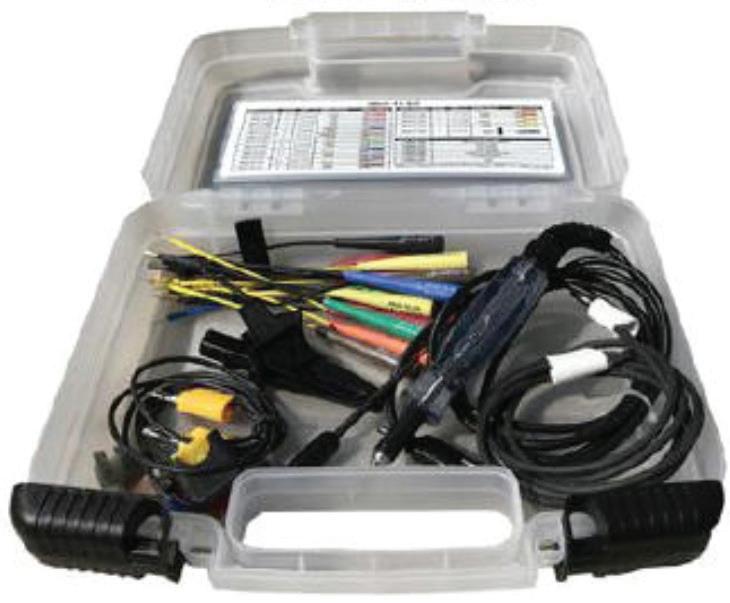
If you work on Mazda vehicles that feature their SKYACTIV system, Mazda offers a SKYACTIV Wiring Terminal Test Kit that allows you to check pin fit drag of all terminals and to compare suspect terminal drag with a known good terminal. The kit also allows you to measure voltage/resistance while avoiding terminal damage. The kit, P/N 49US15-KIT, includes a variety of test leads, a 48-inch white patch cord, a test lamp, test probe, large alligator clip and a fuse jumper. Terminals may be damaged if this kit is not used. Note that the test leads vary in size and feature different types of metal. Inserting the wrong
metal type may peel off the terminal plating. Sounds like this kit is a musthave for SKYACTIV vehicles.
If a customer’s vehicle requires only two new tires (or if the customer opts for only two tires), the best practice is to install the two new tires at the rear axle (assuming of course that you have two used/original tires that are in good condition for use at the front axle). The reason for installing the “better” or newer tires at the rear is to maintain optimum traction at the rear, regardless of drive system (RWD or AWD). This is especially applicable in wet weather conditions to avoid potential oversteer conditions.
Considering the wide spectrum of door mirrors available on today’s increasingly optioned vehicles, check the original mirrors before ordering a factory or aftermarket replacement mirror. Some are manually-operated while most are powered. Some are fixed (non folding) and some are folding. Some feature a heating option and some integrate turn signal and/or lane change alerts. It’s easy to accidentally order the wrong mirror when you’re in a hurry.
Some of today’s engines may tend to exhibit engine oil consumption. Examples include (but certainly are not limited to) various Ford and Kia engines where the OEM may state that oil consumption of 1 quart every 1,000 miles is considered normal. Checking engine oil level should be part of any routine pre-service inspection, but make sure that you take the time to check. If oil consumption is excessive (possibly due to improper piston ring interface with cylinder walls), the vehicle manufacturer may have a test procedure in place to monitor oil loss. In some cases, the manufacturer may opt to replace the engine under warranty.
If the oil pressure warning lamp illuminates, obviously this must be addressed immediately. Of course, the cause may involve a failure to check level resulting in low oil level, failure to change oil well beyond service recommendations (sludge buildup), an engine oil leak or any of several mechanical issues. Be sure to check the oil pressure sender switch. A leaking switch can easily cause the warning light to illuminate.
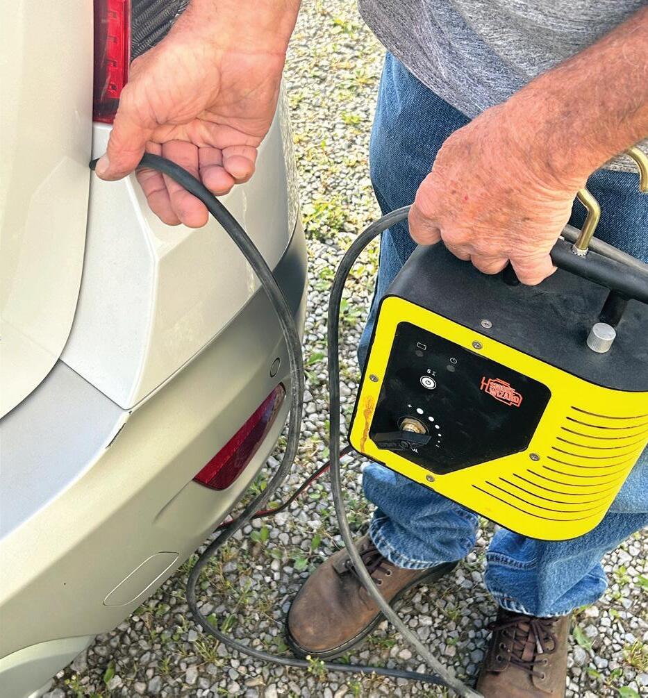
If you encounter a vehicle — more specifically, a SUV or crossover that features a rear hatch — and the customer complains about an overwhelming exhaust smell in the cabin, chances are you’ll focus the inspection on the exhaust system, looking for leaks.
If no leaks can be found, check the rear hatch door for fit. If it’s not sealing properly, perhaps due to a damaged seal or out-of-adjustment door, fumes from the tailpipe can easily roll into the vehicle cabin. Try using a smoke machine.
With the hatch door closed, stick the smoke machine wand into a gap between the body and hatch door. You may find smoke drifting into the interior. The fix might involve replacing the weatherstrip seal or sending the vehicle off to your nearby body repair shop for hatch door adjustment. Just remember that an exhaust leak into the cabin might have nothing to do with the exhaust system itself. Fixing the issue is critical, as exposing the occupants to exhaust fumes can easily lead to carbon monoxide poisoning.
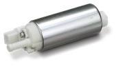

Delphi is driven to apply its OE expertise and technological leadership to engineer each fuel module with stringent standards that deliver the highest level of performance.
With over 85,000+ applications, you can install Delphi parts with confidence.


If you’re working on a 2020-2022 Corvette equipped with a front suspension lift system option, you may encounter DTCs C103C or C103E (left front strut
position sensor signal), with Symptom 64 (signal plausibility failure). The control module detects a single input parameter operating outside the
plausibility range. If previous service work has been done on the system, it’s possible that the issue is caused by air trapped in the system.


Engineered for challenging marine, automotive, transportation and other applications where industrial coatings are applied. The only thing they won’t mask is your craftsmanship.

Attempt to operate the front lift system several times. Determine if the codes will reset or if the system will raise briefly and then sink back down. If this occurs, it may indicate that air is trapped within the front suspension lift system.
Raise and lower the front suspension system through 10 complete cycles. If the DTCs reset, perform the front hydraulic suspension bleed procedure outlined in the service manual. To double-check, you can measure the distance between the floor and the lower portion of the car’s front fascia. A correctly operating vehicle should reach a front fascia height of at least 35mm within four seconds of pump operation.
If a vehicle features a spare tire, during routine service, in addition to checking inflation pressures on all four corners, take the time to also check and correct as needed the spare tire inflation pressure. The spare, if and when it’s needed, won’t do the vehicle owner any good if it is flat.


We’ve all encountered that vehicle that comes from another shop. The one where it seemed every time the right decision could have been made, the technician turned left.
BY CHRIS MARTINO


I WANTED TO tell a different kind of story today. There will be some good diagnosis, a lesson or two, and maybe even a little fun.
I was on the road doing some mobile diagnostics and programming. I received two text messages from a shop where I do some work occasionally. The messages were screenshots of some codes and pictures of some scan data (Figures 1 + 2).
Looking at these pictures, I could see the vehicle in question was a Land Rover that had codes for Cylinder No. 5 injector A circuit — open, and a Cam Position Sensor B Circuit range/performance code.
This was followed by a phone call from the shop owner. The vehicle was a 2018 Land Rover Discovery owned by a childhood friend of his. According to the shop owner, the vehicle owner noticed the vehicle was running poorly and decided to get it scanned. The shop he took it to made the decision the timing was off and recommended the engine be rebuilt. The vehicle owner approved the repair, and the shop sent the vehicle to a local engine rebuild shop.
The truck was at that rebuilder for a few weeks. When the vehicle owner called to check in, the rebuild shop relayed that they were having issues making the truck


run correctly. They scanned it and sent the screenshots to the vehicle owner. The vehicle owner sent them to his friend, and then they made their way to me.
The repair shop (my client) then asked me to go to the engine rebuild shop and give them some direction — as they seemed lost with this Land Rover.
These vehicles need special tools to set the timing chains up correctly, and not using them can cause the engine to be out of time. I told the shop that I would go and check cam/crank correlation with a scope to verify timing and go from there.
I arrived at the engine rebuild shop. The vehicle is outside and someone is working on it. I can see the tech had the spark plugs all out of the driver’s side bank. This was going to be tough to work on. I started speaking with the tech and more of the story began to emerge.
After the engine rebuild, they had the “camshaft code” that would not clear and the fuel injector No. 5 code that would not clear. When they inspected the No. 5 injector, they found it damaged and the internal wiring was exposed. They replaced the injector, but nothing had changed.


same thing? I need to check this for myself.
They asked me if I could check the operation of the cam sensor because they replaced it, but the code would not clear. I happily hooked up my Pico 4425a digital storage oscilloscope, removed the fuel control fuse, and cranked the vehicle. I saw a healthy pattern. I explained to them that this only meant the cam sensor worked. It won’t tell me the camshafts are in time unless I reference all the sensors.
The tech also stated that it was still running rough, and he could not get rid of the injector code. I hooked my scope leads to the fuel injector and cranked the vehicle and saw no signal.
I have learned the hard way that you need to verify your test equipment functionality each time you use it. I connected to battery positive and saw the scope display 12V — this meant my ground reference was good, my leads were good, and my scope was operating correctly.
I hooked the lead to injector No. 4, cranked the engine, and saw a beautiful pattern.
Accessing the Big Picture OK, stop. This is where you need to take a step back and look at the entire picture. This vehicle is at an engine rebuilder shop — post engine rebuild. This engine was out of the vehicle. In layman’s terms, stuff was messed with. This injector harness goes
Fuel injector-No. 1
C1E205E-2
Fuel injector-No. 5
C1E209E-1
C1E209E-2
Fuel injector-No. 3
C1E207E-1
C1E207E-2
Fuel injector-No. 4
Fuel injector-No. 2
0.75, 1351 GN-VT, 0.75, 1281 VT, 0.75, 528
0.75, 608
0.75, 1454
0.75, 1384
0.75, 631
to the back of the engine, joins up with the main harness, and terminates at the ECM, in the left side cowl panel. I need to check these wires to the injector.
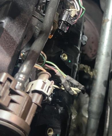
Accessing the ECM is simple for this vehicle. I consulted a diagram and see that the No. 5 fuel injector terminates at pins 26 and 27 (Figure 3). According to the diagram, they are a twisted pair and should be simple to locate. Using an ohmmeter, I found the ignition wire had no continuity and the control wire was shorted to the ignition wire. This made no sense.
I was only asked to come to the shop in an advisory capacity. I advised the shop to check the harness for damage and repair anything they found. If they needed any help, I would only be a phone call away.
I run a mobile ADAS, diagnostics, and programming company. I also have a brick-and-mortar location for jobs that get to be too much for the road. I was at the shop and a tow truck pulled up with a familiar Land Rover on the back. I called the original shop that contacted me. The shop informed me that the rebuilders gave up and the vehicle owner asked him if he could figure it out. This means I get to figure it out.
I got the vehicle in, cranked it up, and it ran...barely. It filled my entire shop with
Module-Powertrain control-PV6
C1E121A-5
C1E121A-26 C1E121A-27
C1E121A-28
C1E121A-29
C1E121A-47
C1E121A-48
C1E121A-91
C1E121A-92
FIGURE 3: THIS OEM ECM wiring diagram sheet shows the fuel injectors are in the harness as a twisted pair and the control as well as the IGN wires are right next to one another in the ECM connector.
white smoke. It felt like it was running on only a few cylinders. It also had an extended crank. A code scan showed many more codes that were not there before — most notably a fuel rail pressure circuit, charge air pressure circuit, and injectors 1, 3, and 5 circuits. We decided to go after the fuel fail pressure fault first. Checking a diagram, we saw that the fuel rail pressure sensor and MAP (charge air pressure) sensor share a VREF (5V) signal (Figure 4).
Upon checking, the 5V reference source was not getting to either sensor, but it was coming out of the ECM (more broken wires). We checked the main harness and could not see where the rebuild shop opened it up. There also did not appear to be any apparent damage to it either. We started at the firewall grommet and removed a couple inches of tape. We found the green VREF wire broken. A simple fix of the wires now brought power to those sensors.
We then cleared the codes and started the vehicle. The extended crank was gone, but it still felt like it was running on only a few cylinders. Another code scan showed cylinders 1, 3, and 5 still open circuit. Hooking up the scope showed no signal coming from the ECM during cranking. We cleared the codes again while the
scope was still connected and cranked it again to see if the computer was shutting the coils down. Nothing ever came out of the computer. This makes no sense. This issue was not there two weeks ago, and as far as I can tell, the engine and harness appear to be in the same condition.
We pulled the ECM connector and checked continuity to the injectors. All the wiring checked fine. The injectors each had about 1.8 ohms, which is perfect for this vehicle. For some reason, the computer was not controlling the injectors. A check of the powers and grounds to the ECM was fine. We had no choice but to diagnose this as a faulty ECM. We called the repair shop, and the vehicle owner approved the replacement of the ECM.
The brand new ECM came in a few days later. We installed it and ran through the programming process with Topix Cloud DDA. The process went smoothly — until it asked me to start and run the vehicle. I cranked the vehicle, and the starter would not turn. It made a weird sound like the starter was binding or the engine was seized.
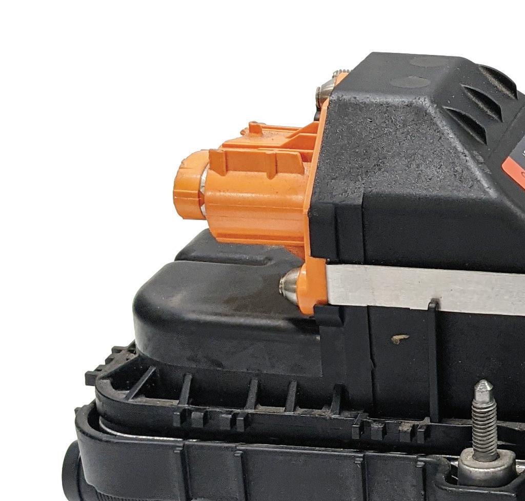
Rolling the engine over with a socket on the front crank pulley showed the engine was seized tight. It seemed hydro-locked. We removed all six spark plugs and started to roll the engine over again. The engine moved freely. Cylinder No. 5 was completely full of fuel (Figure 5) — followed by cylinders No. 1 and No. 3 having a decent amount in them. I had my tech roll the engine over in the suspect to measure the stroke and compare them to the good cylinders. Luckily, they all moved the same and there were no bent rods.
So, let’s recount: so far we have found damage in the wiring harness, damaged electronics in the ECM, and now three fuel injectors. We let the shop owner know the next batch of our findings, got it approved by the vehicle owner, and ordered three new fuel injectors.
We pulled the injectors out to replace
them and saw that the O-rings and seals had not been replaced. For those of you not familiar with this engine, this is a direct injected engine: the fuel injectors run through the valve cover. This engine, just to remind you, has been rebuilt. The rebuild shop never replaced the Teflon seals — these are single use only! That’s a big no-no. We pulled all the injectors out, replaced the seals and O-rings, and installed the three new injectors.
With that much fuel in the cylinders, we decided an oil change was needed to get all of the fuel out of the crankcase. We popped the drain plug and out came seven gallons of fuel! This could have been caused by the stuck open fuel injectors, but I wanted to be sure. This engine uses two high-pressure (HP) fuel pumps mounted on the side of the engine. I have seen this style of pump fail before and leak fuel into the crankcase, causing fuel trim issues and
misfires. Diagnosing this condition can be difficult. Most of the time you must rule out everything else and be left with only the fuel pumps as the remaining fault. This was not good enough for me.
I had the assumption that one or both pumps was leaking directly into the crankcase — how can I test that? These pumps are driven from a separate cam by the timing chain on the right lower side of the engine.
The pumps are fed pressure from the in-tank pump and should hold around 60 psi and rise to 90 when cranking (Figure 6). Once the engine starts to turn, the pumps will develop high pressures. I left the drain plug out of the oil pan and turned the key on, nothing dripped out. I tapped the starter button and then quickly shut it off, and fuel started running out of the drain plug. One or both pumps were leaking into the crankcase.
For those of you keeping a tally of the diagnoses:
• Damaged wiring in the main harness
• Damaged drivers in the ECM
• Three faulty injectors
• Three more sets of injector seals
• Two high-pressure fuel pumps
Another phone call to the shop, and an approval from the customer meant the pumps were on the way. I took all the under coverings, starter, and fuel lines out. I then popped out the pumps to find one
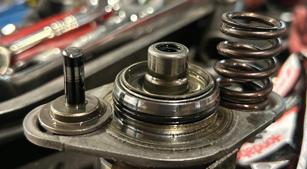
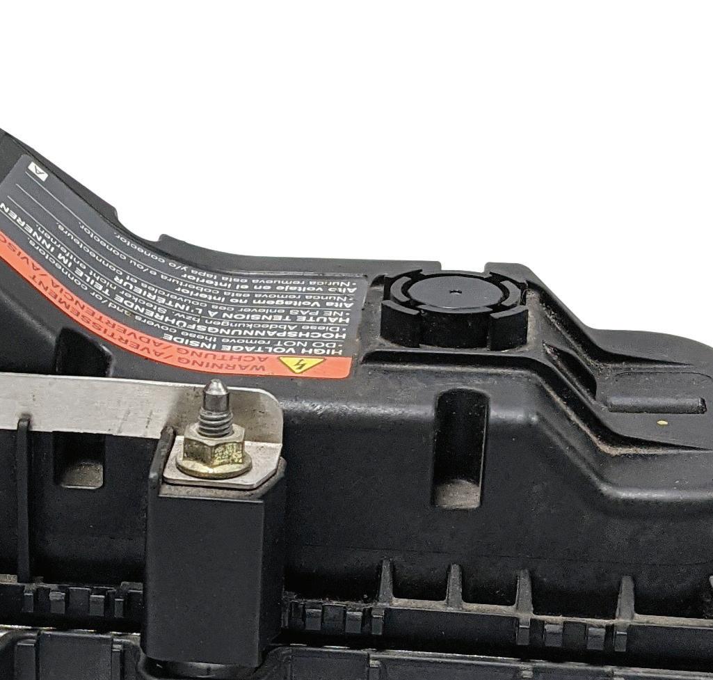
that looked OK, but the other one came out without the spring and piston (Figure 7). There’s the fuel issue. I fished out all the broken parts and installed the new pumps.
Once filled with fresh oil and a filter, I was able to start the vehicle. It started right up and ran relatively well. There was a ton of white smoke coming out of the exhaust due to all the old fuel burning off. After all the smoke cleared (pun intended), I checked the codes again. There were codes for misfires on cylinders 4, 5, and 6, and cam correlation codes (the same ones it came in with) (Figure 8). All signs pointed to the timing being off on one bank. I let the shop owner know where we were at, and he asked me to prove the timing was off.
I usually like to do this the easy way: cam/crank correlation, but I decided to get fancy and use an in-cylinder pressure transducer. My plan was to take a
2. P0018-76 Crankshaft Position - Camshaft Position Correlation Bank 2 Sensor A[P0018] - Wrong Mounting Position Confi rmed
3. P0391-00 Camshaft Position Sensor B - Circuit Range/performance (Bank 2).No Sub Type Information
rmed
4. P0300-00 Random Misfi re Detected. - No Sub Type Information Confi rmed
5. P0304-00 Cylinder 4 Misfi re Detected. - No Sub Type Information Confi rmed
6. P0305-00 Cylinder 5 Misfi re Detected. - No Sub Type Information Confi rmed
7. P0306-00 Cylinder 6 Misfi re Detected. - No Sub Type Information Confi rmed
8. P1315-00 Persistent Misfi re - Catalyst Damage. - No Sub Type Information Confi rmed
9. P0316-00 Misfi re Detected On Start-up (First 1000 Revolutions).No Sub Type Information Confi rmed
10. P131A-00 Low Fuel Level Detection - No Sub Type Information Confi rmed
and
the timing bank to bank.
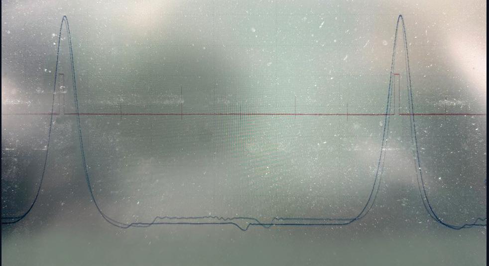
capture on each bank and overlay them. An in-cylinder pressure waveform, in my opinion, can be the best way to visualize individual valve events without taking anything apart.
I am not a guru at this, I leave the high-end deciphering work to my friend Brandon Steckler. However, I was always good at playing “one of these things is not like the other.” We hooked the in-cylinder transducer up, saved the captures, and I put them in an overlay program (Figure 9). You can clearly see that there is a difference from side to side.
Let’s
What is off and by how much? I’m going to let you in on a secret; it doesn’t matter in this case. Does knowing that the intake cam is off 33.67893245 degrees change the fact that this brand-new chain will have to be reset? Nope. My diagnostic urge has been fulfilled and I am now able to report the final findings to the customer.
Could the hydro-locked engine have caused the chain to jump? Maybe. The bank causing the code was on the same side as the completely full cylinder. This vehicle had the engine so diluted with fuel that it may have caused the tensioners not to hold pressure and allow the chain to jump. Could the chain not have been set up correctly at all? Again, maybe. There is no way to prove that. When I was at the rebuilder’s shop originally, I asked if they used the proper tools to assemble the chain, and they responded that they did. I have no reason to doubt them. I can only speak to where the diagnosis led me.
I reported my findings to the shop owner, and he relayed them to the vehicle owner. The vehicle owner was done at this point — and probably mad at himself for not taking it to his friend from the beginning. He asked that we put the vehicle back together and he was going to call it
a loss and trade it in for something less troublesome and complicated.
We reassembled the vehicle and drove it back to the repair shop, and aside from the flashing check engine light, it didn’t drive half bad.
Is there a moral to this story? I don’t know. I can tell you that I trust my diagnostic process. When I had to make a call — no matter how bizarre and unbelievable it was — I felt confident.
I can relay that to you: build your process — trust your process. Don’t deviate even though something may be unbelievable. These vehicles are only machines and follow simple rules when broken down to their base systems. Don’t discount the human factor; humans are fallible and can really mess things up whether we want to or not. And sometimes, after all this, you will have a good story to tell for years to come.

SCAN TO READ MORE OF CHRIS MARTINO’S ARTICLES.

CHRIS MARTINO is a member of Trained By Techs and co-owner of ADAS LI, an ADAS diagnosis, calibration and programming solutions provider on Long Island, NY. He spends his days analyzing challenging and problematic vehicles and spends his evenings working to better the automotive service industry with his fellow Trained by Techs members. His specialty is electrical fault diagnosis using advanced efficient troubleshooting techniques but with a focus on the basics.

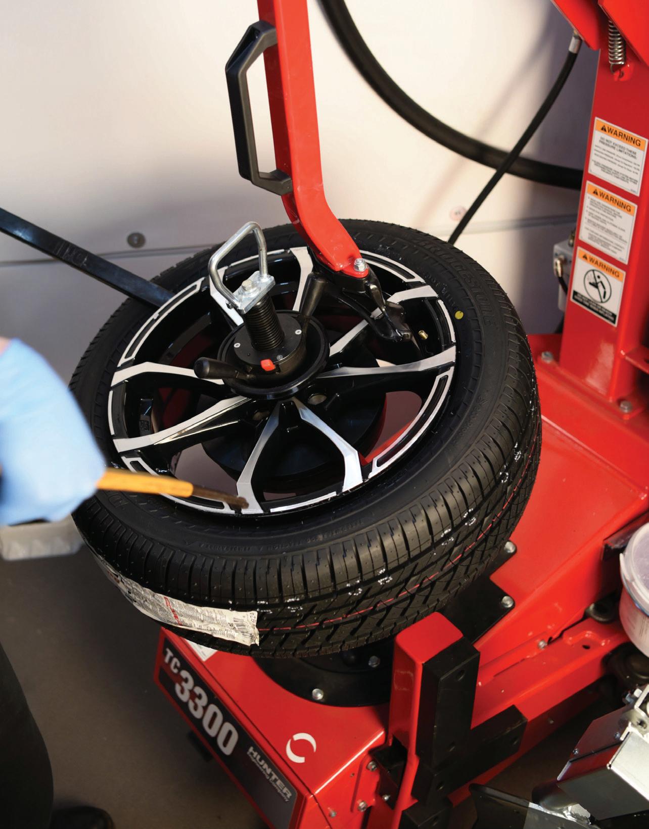
Optimizing tire/wheel imbalance and radial runout.
BY MIKE MAVRIGIAN

TIRE-TO-WHEEL MATCH MOUNTING is an effort to minimize the effects of either imbalance or radial force variation (RFV). This is done by mounting the tire onto the wheel in a specific clock position in order to counteract the tire’s high point of RFV to the wheel’s low point or radial runout, or to align the tire’s lightest point of weight to the wheel’s heaviest point of weight. Either of these corrections are traditionally made possible by aligning color dot(s) on the tire to specific locations on the wheel.
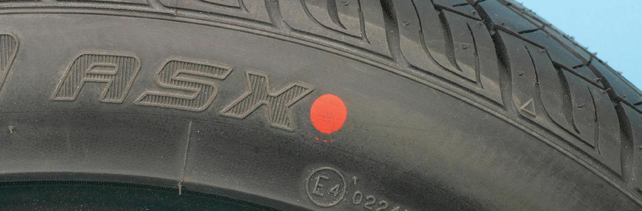
New tires may feature a red dot on the sidewall. This red dot indicates the tire’s uniformity in terms of greatest/highest/ stiffest point of radial runout force (maximum RFV). When mounting the tire, this red dot should be aligned to a white dot on the wheel (if the wheel is so marked). The white dot indicates the wheel’s minimum radial runout point. (On a steel wheel, a dimple may be featured that indicates the wheel’s low point.)
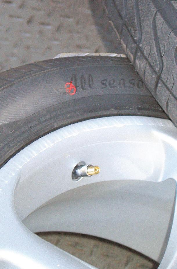
When using alloy wheels that don’t have a white dot, the tire’s red dot should be aligned with the wheel’s lowest runout point (which may be the valve stem). If the wheels feature no low runout indication, the low runout point may be determined by measuring wheel runout with the use of a dial indicator.
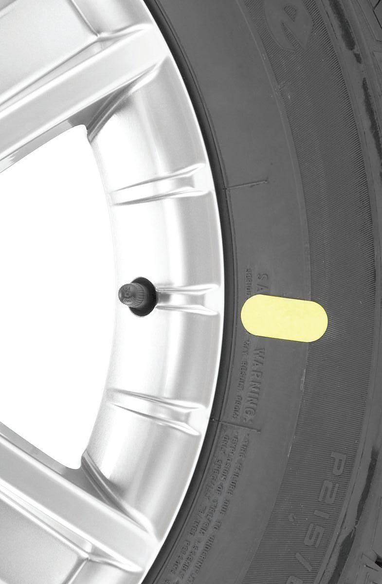
A yellow dot on the tire sidewall indicates the lightest point of the tire (in terms of weight from a balance consideration). If a yellow dot is found, this should be aligned with the wheel’s valve stem, which should be the wheel’s heavy spot in terms of balance. (The valve stem area becomes more of an issue with the added weight of a TPMS sensor.) If the tire features both red and yellow dots, it is preferred to use the red dot as a priority, assuming you can locate the wheel’s low point.
• Red dot on tire (uniformity match): Align to the wheel’s low-point.
• Yellow dot on tire (weight match):
Indicates the tire’s lightest point. Align to the wheel’s valve stem.
• Both red and yellow dots on tire: Where possible, the red dot takes priority. Align the red dot to the wheel low point.
NOTE: Not all wheels indicate the point of minimum radial runout. If the point of minimum radial runout is not indicated, and you prefer not to manually measure the wheels for runout, the weight method of match mounting should be used. (Look for the yellow tire mark to pair with the heaviest point of the wheel).
While some tires may feature painted color dots, some tires today use a temporary sticker. The same goes for alloy wheels — a sticker may be present to indicate the wheel’s low spot. Unfortunately, as a result of the handling of the tires and wheels during shipping and subsequent handling in a warehouse or shop, these stickers may have gotten dislodged, eliminating any reference points.
In addition to checking and correcting imbalance issues, we need to consider how tire-to-ground load affects the tire’s rolling uniformity.
Radial force variation (known as RFV) refers to the radial/out of round variation of the tire under load. Note that the term “radial” as used here does not have anything to do with the type of tire (radial or bias ply). Rather, this refers to the radius of the mounted tire in a loaded condition.
Given the nature of manufacturing, it’s very difficult if not impossible to make a tire that maintains perfect roundness (consistent radius) when the tire is subjected to load. Due to tire construction where multiple layers of material are involved, there may be a point on the tire that is a bit heavier or stiffer, creating a slight out-of-round when road forces compress the tire due to the isolated area of tire construction stiffness. Vibrations caused by RFV are often mistakenly perceived as an imbalance issue, making the technician or vehicle owner believe that
the problem is being caused by a poor balancing job.
These slight variations can result in a vibration at certain speeds, even though the tire and wheel assembly has been weight balanced. In order to fine tune the tire-to-wheel assembly, these slight manufacturing tolerances/tire construction subtleties can be compensated for by match mounting (also known as phase matching). The goal is to align the tire’s point of maximum RFV (the high point of the tire) to the wheel’s point of minimal runout (the low point of the wheel) in an effort to compensate for the dynamic effect of the tire’s high/stiff point.
Radial force is determined by measuring loaded radial runout. On a typical passenger vehicle tire/wheel assembly, 0.001-inch of loaded radial runout is equivalent to about one pound of road force. As an example, a measured 0.030inch of loaded radial runout (resulting in about 30 pounds of road force) will cause the same amount of vibration as about 2 ounces of wheel imbalance at 50 mph.
A minimum range of between 0.3 to 0.5 ounce (7-14 grams) of imbalance is usually enough for the average motorist to notice an imbalance-induced vibration. If a vehicle is sensitive enough to exhibit noticeable vibration at only 0.3 to 0.5 ounces of imbalance, that same amount of vibration may be present with as little as 10 – 15 pounds of radial force variation. It may be surprising to learn that this can be caused by as little as 0.010” to 0.015” of loaded radial runout. It’s easy to see how loaded runout can dramatically affect vibration. In other words, what may seem as a miniscule level of loaded tire runout variance can result in a notable impact on operating smoothness or harshness.
Unfortunately, the dot placement method is no longer useful in all applications. While the rule of thumb has been to align tire dots to wheels, it has been found


that aligning dot markers doesn’t always compensate for weight balance issues or correct a potential RFV, although in theory it should. Today, use of a road force machine is the most accurate method of correcting for RFV.
Red dot alignment may not work with all wheels today, which may require a change in approach. Today, some alloy wheels (and even some OE wheels) no longer provide the same valve stem reference points. Due to ever-evolving wheel design, especially in the realm of aftermarket wheels, some alloy wheels now feature the valve stem location that prioritizes aesthetic concerns, rather than indicating a wheel’s point of minimal radial runout. As a result, we can no longer guarantee
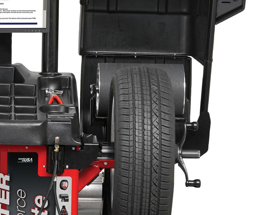
IN ORDER to address both balance and radial force variation issues, balancing centers such as this Hunter Road Force Elite system feature a road wheel, allowing a simulation of how the assembly performs as the vehicle is driven. This type of equipment is indispensable in solving “mystery” vibration issues.
that valve stem placement is an accurate indication of loaded runout.
This means that match mounting by utilizing the colored dots on the tire may or may not get you “close” to minimizing or eliminating imbalance and/or runout issues.
The only method to accurately achieve correction is to use a balancing machine that enables you to measure runout and road force variations, such as Hunter’s Road Force Elite wheel balancer. This level of balancing equipment automatically measures wheel loaded runout and balance state, providing precise location for adding weights. The tire/wheel assembly is then “road tested” by loading the tire against a road force bar, indicating any radial force
variation issue. Resulting data indicates potential need to remount the tire in a different clock position on the wheel in order to minimize or cancel out any RFV.


A balancing machine that incorporates a load feature will not only check for dynamic balance but will also locate the tire’s high spot. If this high spot doesn’t correlate to the wheel’s low spot, the machine will let you know where to relocate the tire on the wheel to minimize RFV.
As you can likely gather at this point, tire “match mounting” is no longer as simple as using the dots on a tire sidewall. An approach to match mounting will depend on several variables.
Regardless of the approach you take, it’s important to understand that “stacked-up” runout and imbalance conditions can be diagnosed and addressed.


If you don’t have access to a road force machine, you may continue to use the dotto-valve stem method (if available). Again, this may or may not minimize the required balance weights, and it may or may not minimize or cancel out a radial runout condition. You can always manually check the wheel for radial runout by mounting the bare wheel to a hub and using a dial indicator, in which case you can continue to use the red dot to align it to the wheel’s point of minimum runout. If imbalance issues persist, move the position of the tire at the wheel by 90-degree increments and test. By relocating the tire relative to the


wheel, you can minimize radial runout by locating the tire’s high spot to the wheel’s low spot. Balance weights will likely still be needed, but this may reduce the amount of required weight.
A perceived imbalance issue may be due to radial runout. Runout may be caused by the hub, wheel-to-hub interface, wheel runout, or the mounting position of the tire to the wheel. If dynamic balance is verified, begin measuring for excessive runout. First check hub runout in order to identify or eliminate the hub as the
possible root cause. A stack-up issue is possible if both the hub and wheel feature runout. If the high point of the hub aligns with the high point of the wheel, this compounds the resulting runout condition. If runout of the hub and wheel have been measured independently, remount the wheel so the high points of each component are 180 degrees apart in an effort to cancel the effect.
NVH (noise/vibration and harshness) issues can exist due to various conditions involving the vehicle’s suspension, brakes, engine, drivetrain, etc. However, diagnosing and addressing the tire and wheel assemblies is a good starting point. Consider the basics first: tire brand and model (all should match), tire size, and adjusting all tire inflation pressures to specification. It’s also vital to inspect and feel the tread for unusual wear patterns. Check the tire and wheel for proper bead seating along the entire bead circumference on both sides. An improperly seated bead can easily create a radial runout condition.

SCAN TO READ MORE OF MIKE MAVRIGIAN’S ARTICLES.

MIKE MAVRIGIAN has written thousands of automotive technical magazine articles involving a variety of specialties, from engine building to wheel alignment, and has authored more than a dozen books that crisscross the automotive spectrum. Mike operates Birchwood Automotive, an Ohio shop that builds custom engines and performs vintage vehicle restorations. The shop also features a professional photo studio to document projects and to create images for articles and books.


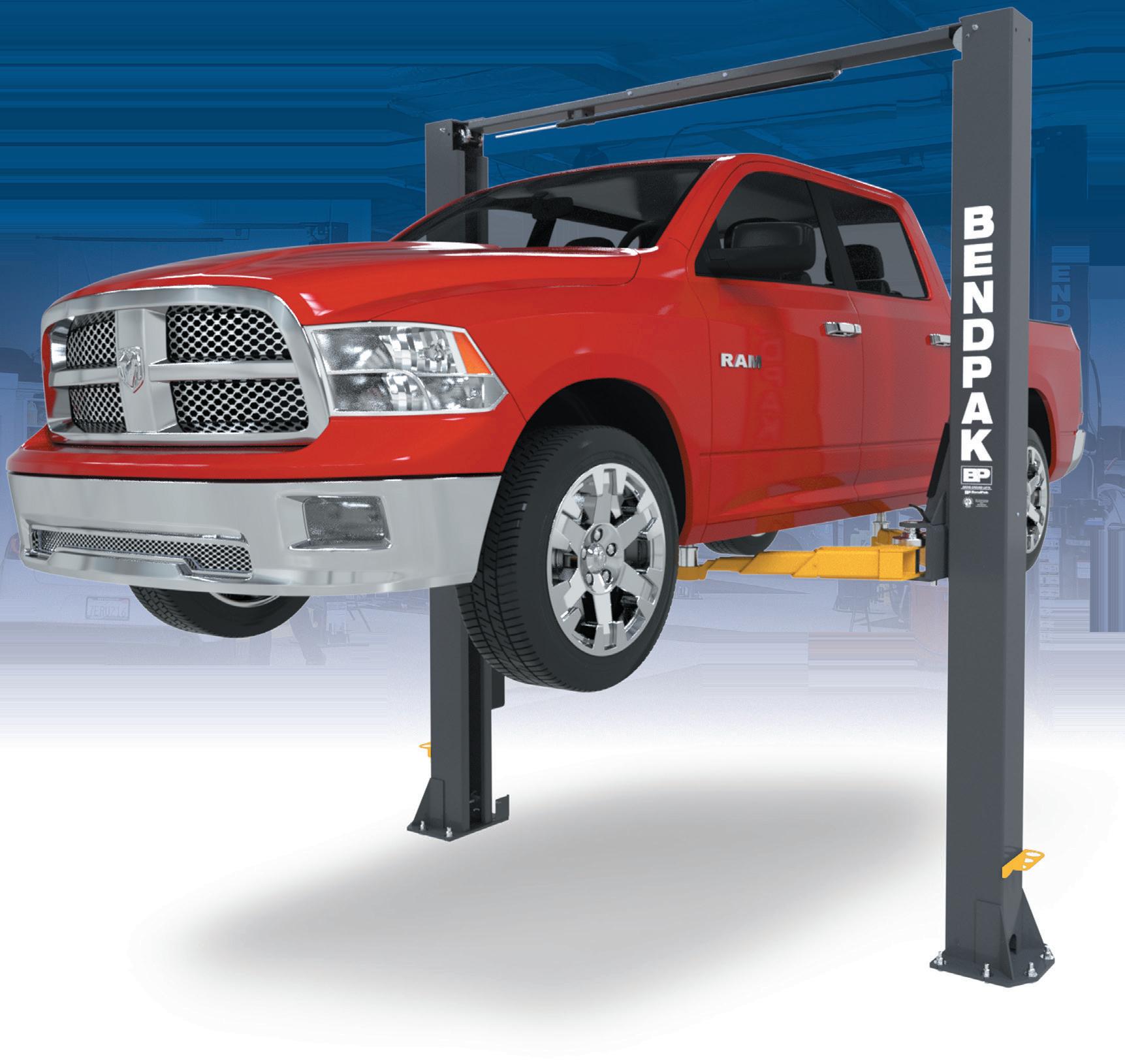
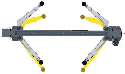
Our 10AP Series offers the convenience of wide or narrow installation wrapped up into one configurable package. This durable, safe, and reliable car lift features an expandable top beam and BI-METRIC™ arms to suit virtually every vehicle lifting requirement – symmetric or asymmetric. The 2-in-1 design gives operators the option of loading vehicles either symmetrically (centerline of vehicle at column) or asymmetrically (centerline of vehicle behind column). The simple, yet highly sophisticated is sure to keep operating costs low and productivity high. Check out the full line of 10AP lift series at bendpak.com or call us at 1-800-253-2363


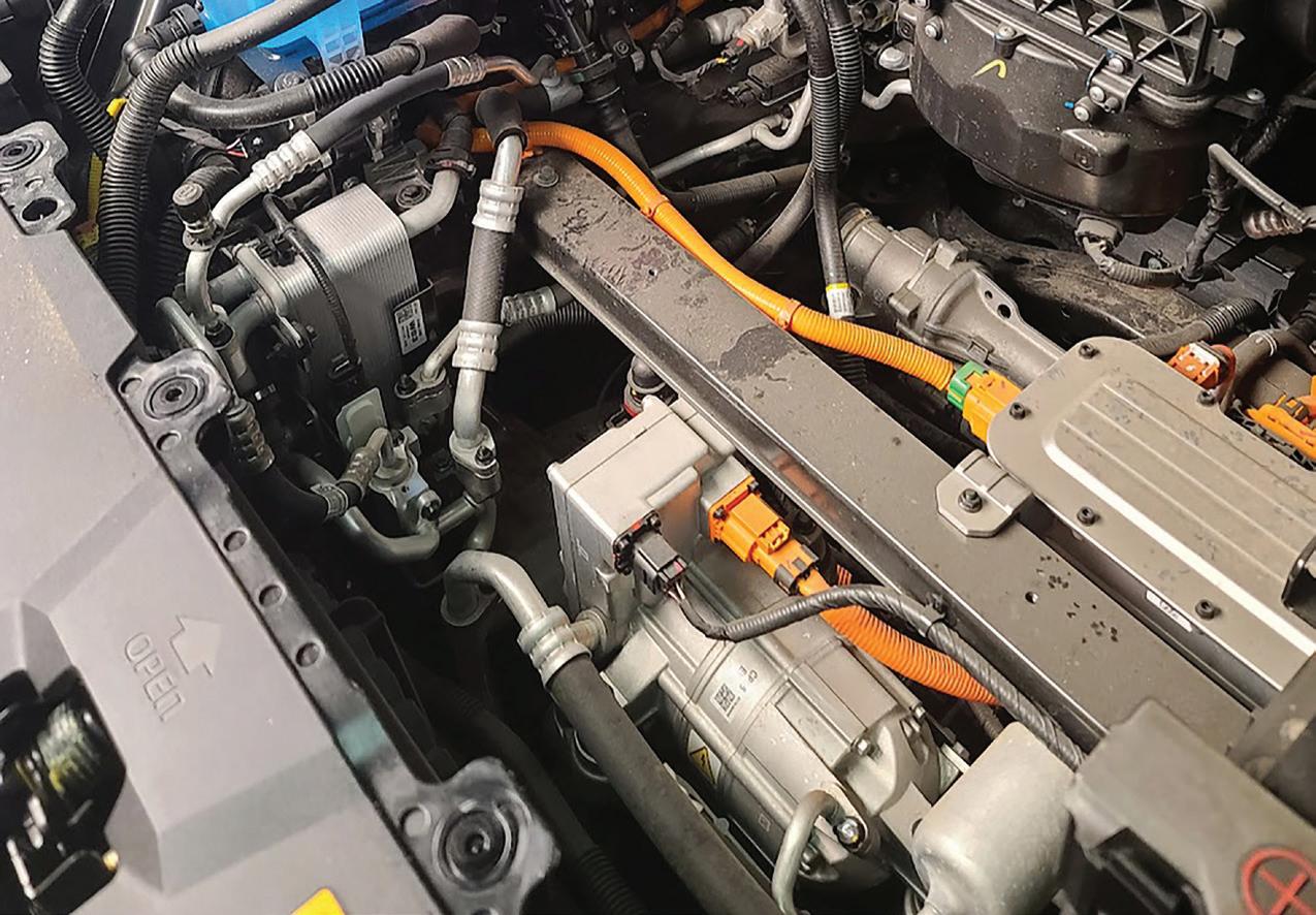
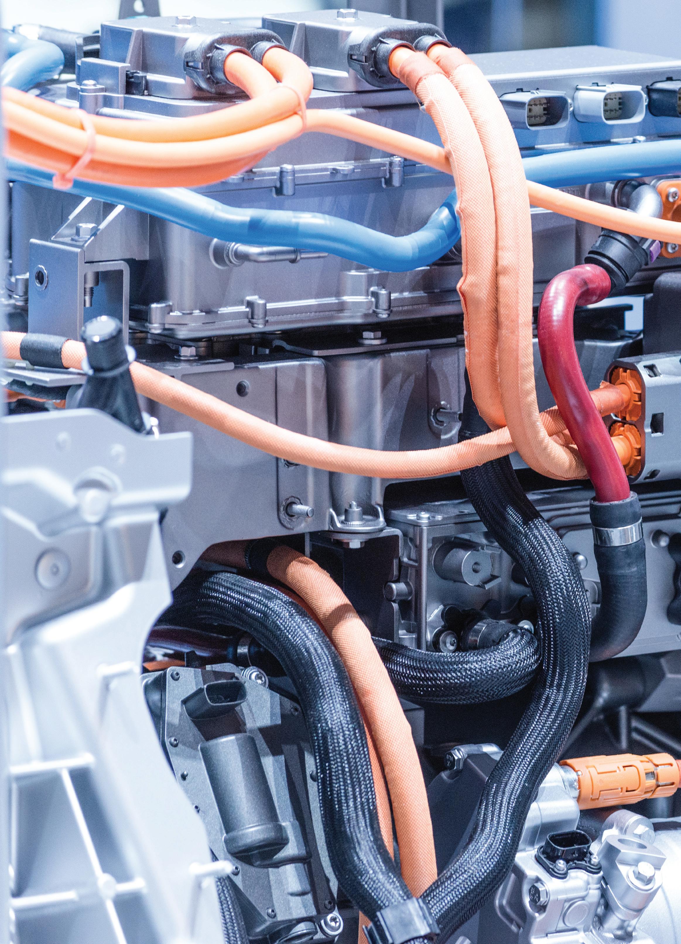
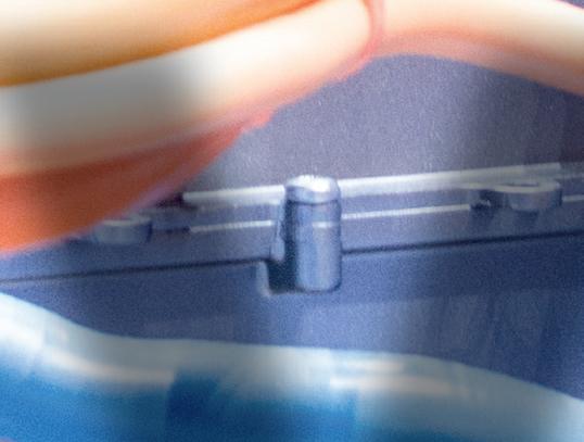
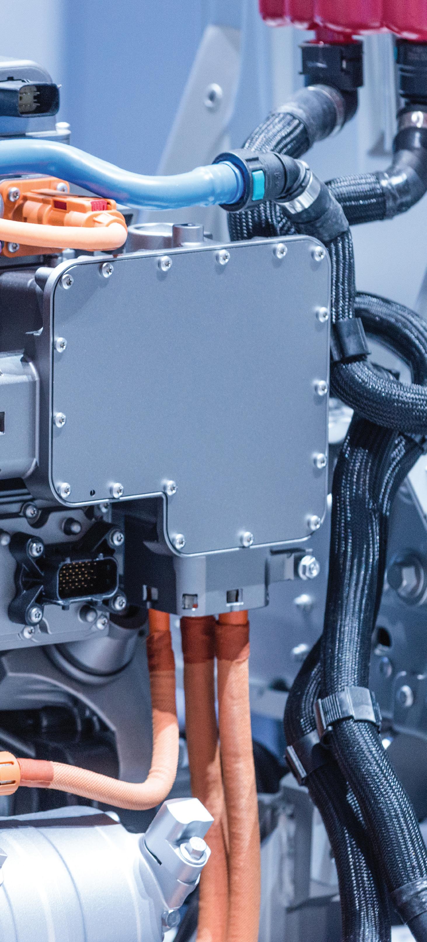
Prompted by HEVs, PHEVs and electric vehicles, the use of electric compressors offers distinct advantages.
BY JEFF TAYLOR


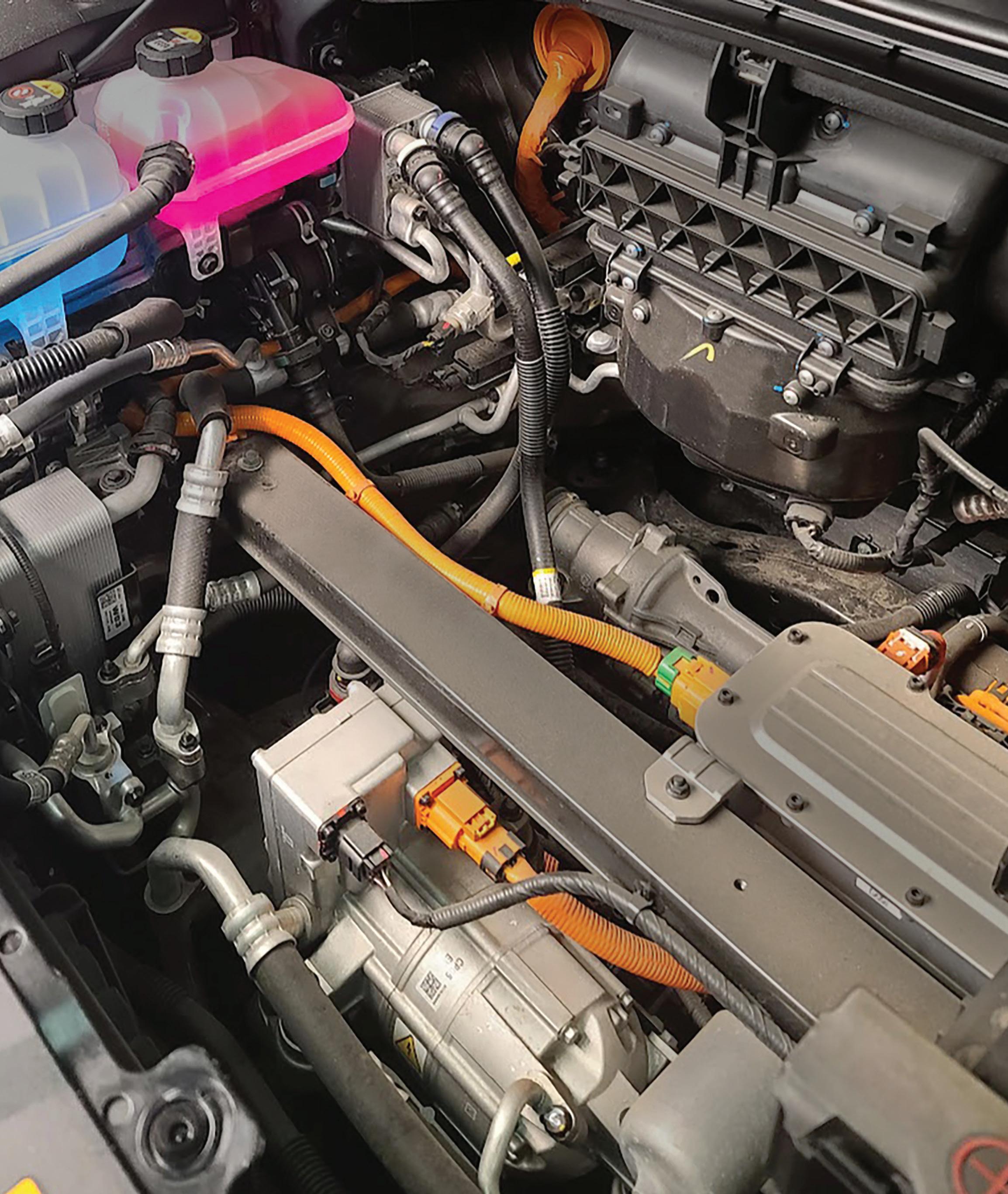
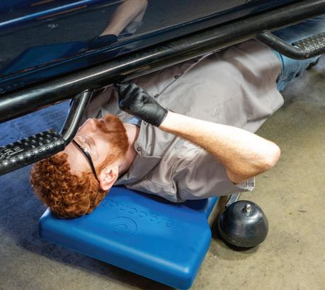
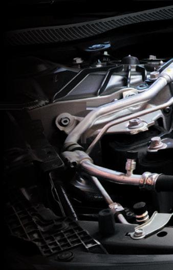
WITH THE trim panels removed you can see all the extra plumbing involved in this heat pump equipped 2023 Hyundai IONIQ 6; this illustrates the need to follow the diagnostics to remove or service the A/C system.


The air conditioning (A/C) system in vehicles has provided essential comfort and convenience since its debut in 1939 by the Packard Motor Car Co. Before the rise of today’s popular Hybrid Electric Vehicles (HEVs), Plug-In Hybrid Electric Vehicles (PHEVs), and fully Electric Vehicles (EVs), the Internal Combustion Engine (ICE) not only provided motive power but also supplied energy for nearly all the onboard systems, including the A/C compressor.
The traditional A/C compressor drew power from the crankshaft through a system of belts, pulleys, brackets, and tensioners.
Engineers already faced considerable challenges in achieving the best climate control with smaller displacement engines and start-stop features that limited ICE operation, but hybrid and fully electric vehicles present another ballgame all together.
The introduction of HEVs, PHEVs, and EVs revealed a significant drawback in the traditional ICE-powered, belt driven A/C compressor: it only works when the engine is running, and on EVs, there isn’t an engine at all. The last thing automotive manufacturers want is uncomfortable drivers or passengers in their vehicles limiting A/C compressor operation when the vehicle is in start-stop mode.
To solve this major issue, a new generation of automotive A/C compressors powered by electricity, rather than a crankbelt-driven system, was developed. This led to the creation of the high-voltage electric A/C compressor.
The high-voltage electric A/C compressor is a significant advancement in automotive technology, compared to its ICEdriven counterparts. One major difference is that the electric A/C compressor can run at variable speeds, often controlled via Controller Area Network (CAN) protocols. This allows for optimal compressor speed and operation, resulting in the best climate control under various driving conditions.
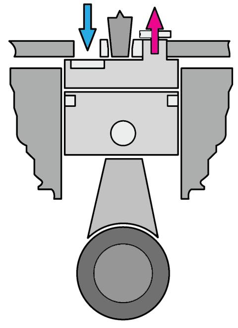
The electric A/C compressor will use a scroll type compressor assembly, unlike conventional piston-based compressors. It works without valves, achieving nearly 100% volumetric efficiency. This efficiency reduces the energy needed for A/C compressor operation, as there are no re-expansion losses associated with each piston stroke and the energy losses created by valves are eliminated.
Another advantage of electric A/C compressors is their ability to precisely control the compressor speed, using a brushless threephase AC motor. This precise control optimizes energy consumption, thereby increasing the vehicle’s overall range (something that is important to EV owners). Electric compressors are also more compact and lighter, resulting in weight savings of up to 20% compared to traditional ICE-powered compressors.
In the first generations of electric A/C compressors, distinct designs were employed, differing significantly from today’s common electric A/C compressors. For instance, Honda used a dual scroll three-phase AC design that incorporated a traditional beltdriven scroll and an AC electrically driven scroll section. This
design allowed for three separate phases of operation: combined operation of the belt and electrical scrolls for maximum cooling, belt-driven scroll only, and variable-speed electrical scroll operation only. Neither the belt-driven or electrical-driven parts of this A/C compressor could supply the needed maximum cooling alone, so when maximum cooling was requested by the operator, both sections would be in operation.
Another common feature of early electric A/C compressors was that the electric motor driving the A/C compressor was supplied with three-phase AC power via three heavy-duty cables from the vehicle’s power inverter, or a dedicated A/C compressor driver/ controller. This design is no longer common. Today’s electric A/C compressors are supplied with high-voltage DC electrical power directly from the DC high-voltage battery system to an integrated power inverter, incorporated into the electric A/C compressor itself.
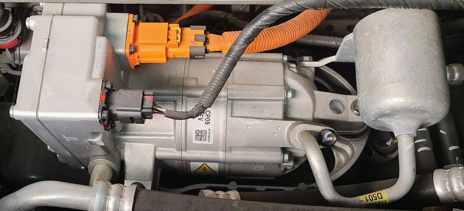
There are two main electric A/C compressor designs used today, depending on the location of the Power Inverter Module (PIM): top-mounted or rear-mounted, with the trend moving towards rear-mounted. When combined with a redesigned electric motor, this shift to a rear-mounted inverter reduces the compressor’s length, width, and weight by about 10%.
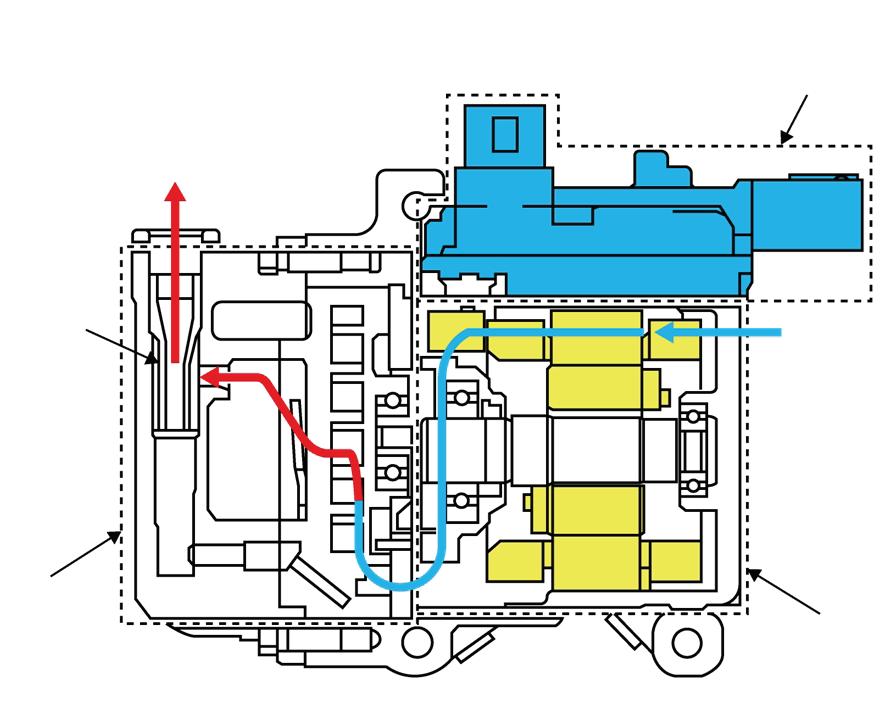
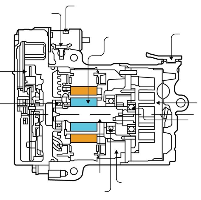
The typical electric A/C compressor will have four separate sections: compressor section, motor section, PIM section and oil separator section. Each of these sections plays a significant part in the way that these compressors function.
Let’s examine each of these sections.
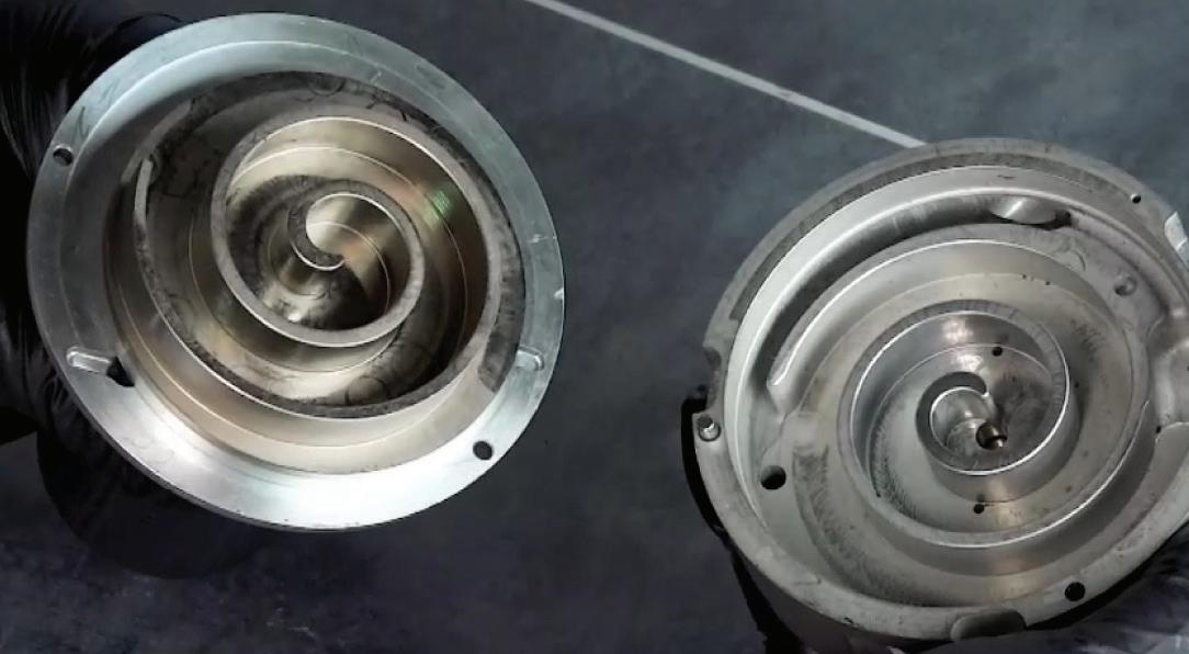
Compressor Section: This section handles drawing in, compressing, and discharging the refrigerant. The scroll A/C compressor will use a spirally wound fixed scroll and a rotating scroll (similar to the operation of a supercharger), which will compress the refrigerant by gradually wedging it into a smaller space as the scroll rotates. This scroll design offers significant advantages over traditional compressors.
The scroll design dramatically reduces noise and vibration. Unlike conventional piston-based compressors, which rely on reciprocating motion, the scroll compressor’s continuous, smooth operation minimizes mechanical noise and vibration. This reduction in noise and vibration is particularly crucial in electric vehicles, which lack an internal combustion engine to mask these sounds with background noise.
The scroll mechanism also ensures a more consistent and steady compression process, leading to improved efficiency.
Motor Section: This section houses the DC brushless motor that drives the compressor, featuring a permanent magnet rotor and a coil stator. The three-phase brushless motor, typically controlled by a three-phase PIM, has windings with high-voltage insulation designed to withstand refrigerant oils. This setup enhances efficiency and torque output, crucial for compressor operation. With an output rating of 1.8-2.4kW, electric compressors are slightly less powerful than their ICE-belt-driven counterparts, which have ratings of 4.0-5.0kW.
Equipped with an eight-pole permanent magnet rotor, the typical three-phase electric A/C compressor achieves higher speeds and strong torque, essential for optimal performance. The stator
(Low-Temperature, Low-Pressure)
(High-Temperature, High-Pressure)
windings, configured in a WYE formation, are connected to the PIM for operational control. Speed regulation is achieved through PIM current sensing on the WYE windings.
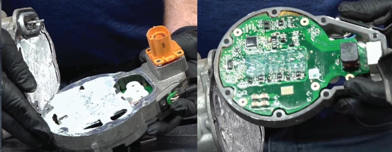
Power Inverter Module Section: Most electric compressors will integrate the PIM, streamlining high-voltage and control/ communication connections and reducing wiring complexity. Alternatively, a remote-mounted PIM can supply the necessary three-phase high voltage through separate connections and cabling. The PIM houses electronics that power the compressor via six connection points, using transistor drive networks, including two Insulated Gate Bipolar Transistors (IGBT) per phase for control. The PIM controls the electric A/C compressor speed control through PWM (Pulse Width Modulation) of voltage output signals and current to the IGBTs, adjusting all three phases as needed to regulate compressor RPM. With the PIM mounted on the compressor body it provides the needed cooling to remove the heat from the electronics via the refrigerant passing into the compressor.
Higher current to the stator from IGBT controls results in increased motor torque, while the frequency of the control signal, measured in Hertz (Hz), determines motor speed, typically ranging from 0-50Hz (0-1,000 rpm) to around 375Hz (approximately 7,000 rpm). Manufacturer-specific variations may exist, such as the BMW i3’s electric A/C compressor motor, which operates within a specific rpm range, allowing stepless adjustment within that range. For diagnostic purposes, symmetrical Hz patterns across the three phases are essential, especially when the PIM is remotely mounted. Some of the newest high-voltage electric A/C compressors will operate at 800V and can run continuously at 8,600 rpm. Electric scroll-type compressors maintain almost constant torque at any speed due to consistent compression, resulting in nearly constant electrical current. In addition to IGBT transistors, the PIM incorporates detection circuits for overload conditions and other critical parameters, ensuring operational safety and efficiency.
Oil Separator Section: In any air conditioning system, including those with electric compressors, lubricating oil is essential for ensuring the smooth operation of moving parts and preventing wear and tear. However, excess oil circulating in the refrigerant system can lead to various issues, such as reduced efficiency by impeding the heat transfer process within the system, decreased cooling capacity, and potential damage to components. The oil separator plays a crucial role in managing the distribution of oil within the system, ensuring that only the necessary amount of oil is present in critical areas, such as the compressor.
By effectively removing excess oil, the oil separator maintains optimal heat transfer properties, ensuring the A/C system operates at peak efficiency. This results in effective cooling, reduced energy consumption, and improved overall performance.
Technicians must be mindful of significant differences when diagnosing an A/C system equipped with a high-voltage electric compressor, particularly in the case of HEVs, PHEVs and EVs. Unlike conventional ICE-equipped vehicles, where a malfunctioning compressor might result in partial or complete system bypass, the electric and hybrid vehicles heavily rely on
air conditioning functionality. Neglecting to maintain the proper operation of the HVAC and electric A/C compressor can lead to excessive heating of critical components such as the high-voltage battery and electronics as the HVAC system is often used to remove this excess heat.
In the case of many new vehicles, especially HEVs, PHEVs, and EVs, the days of installing a bypass pulley, removing the drive belt, or not repairing the HVAC system will no longer be an option.
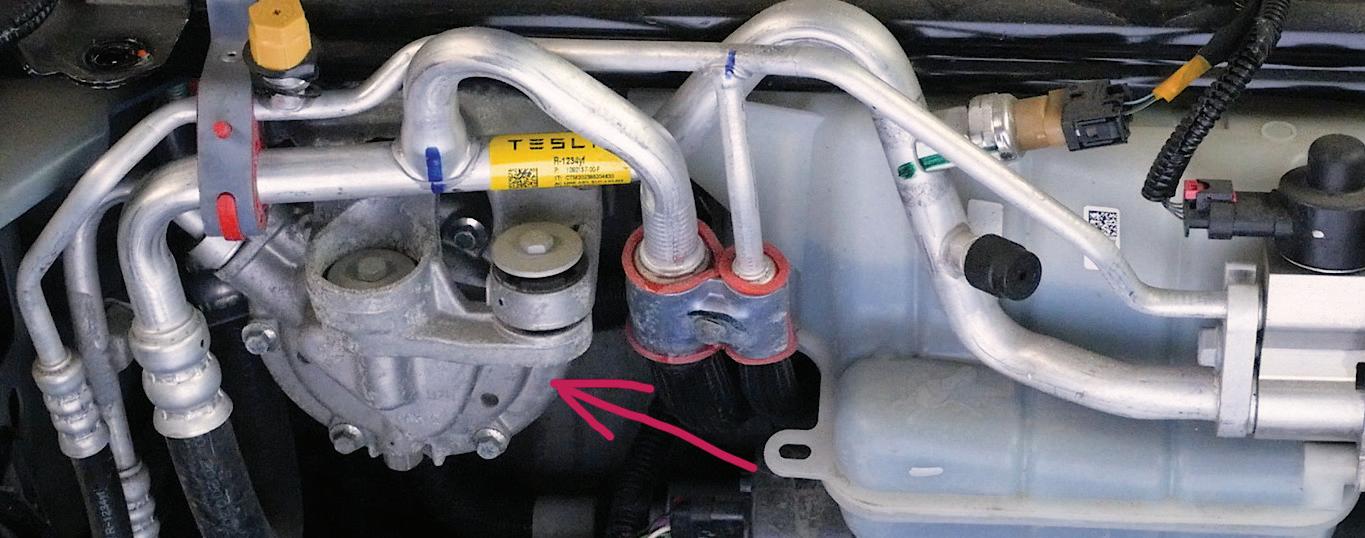
The HVAC system and its components, especially the electric A/C compressor, are now considered a vital part. On a Tesla for example, which will be equipped with an electric A/C compressor, a failed A/C compressor could lead to an overheating high-voltage battery and that can activate safety measures that limit certain vehicle functions. Tesla employs advanced battery management systems to watch temperature, voltage, and charge status for safe battery operation. If the battery temperature exceeds safe levels, thermal management systems like cooling fans or liquid cooling are activated to dissipate heat. In severe cases, the onboard computer may take protective actions to prevent battery damage and ensure vehicle and occupant safety. These measures may involve reducing power output, temporarily disabling features, or even shutting down the vehicle until the battery cools down. Tesla vehicles prioritize safety with multiple layers of protection against battery overheating.
Before we look at diagnostics on a high-voltage A/C compressor setup, we need to talk about safety. Because these systems function with high voltage and compressed refrigerant gas, we need to take certain precautions. It is imperative to understand the risks associated with high voltage. These vehicles are equipped with a high-voltage battery that is completely isolated from the chassis ground. Testing high voltage circuits should only be conducted using a DVOM and test leads with at least a Cat III rating. It cannot be emphasized enough that failure to adhere to the manufacturer’s safety procedures could lead to severe injury or even loss of life.
Diagnosing a failure of a high-voltage electric A/C compressor will almost always involve the use of a scan tool and following the factory Diagnostic Trouble Code (DTC) procedures to repair the issue.
But many DTCs related to electric A/C compressor diagnostics can be intimidating when they are followed, as they will often not include any diagnostic steps other than the replacement of failed components named by the DTC.
For instance, a 2024 Chevrolet Silverado EV that has set a DTC P1C08 (A/C Compressor Motor Speed Too Low) and the MIL is illuminated. This DTC will set if the requested compressor feedback speed is less than 500 rpm for four seconds. The diagnostics for this code are as follows: ignition on, vehicle in service mode, scan, and if this code is set, replace the G1HV Air Conditioning with Motor Compressor. If after replacing the G1HV Air Conditioning with Motor Compressor the issue continues, and sets the same DTC, replace the K16 Battery Energy Control Module.
There is no diagnostic testing, no diagnostic circuit tests, no performance tests, just the installation of a new component.
But that doesn’t mean that we can’t do some testing. Because the electric A/C compressor uses high voltage, there are ways that we can inspect the three-phase motor that spins the compressor, and this can aid if we get specific codes that are related to an internal electrical compressor motor issue.
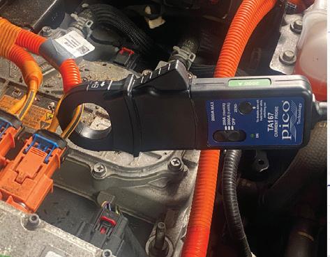
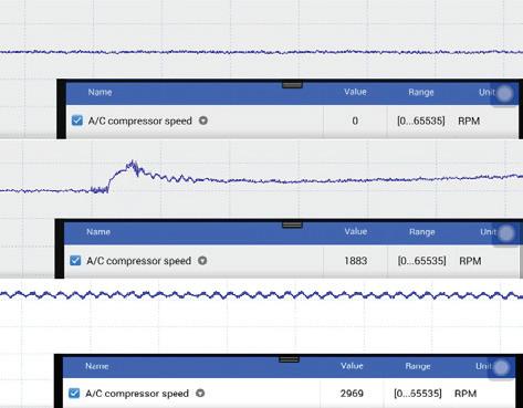
Most electric A/C compressors use an internal PIM for threephase control. When testing, we can monitor the current used by
the electric A/C compressor via the high-voltage DC input using an oscilloscope and a single DC current amp clamp. The in-rush current is typically four-to-six times the normal operating current, which lowers to a steady-state based on HVAC demands. After the compressor starts and stabilizes, we can check the current and examine the DC ripple in the waveform. Consistent and even ripples show good compressor health, while significant deviations may signal an internal issue in the stator, PIM electronics, or rotor. An electrical noise from the electric A/C compressor (think bad diode in an alternator) could indicate phase issues. Such issues often require replacing the entire compressor unit, except for Hyundai or Kia products, which allow separate replacement of either the compressor/motor/oil separator unit or the PIM assembly.
Hyundai and Kia have a diagnostic trouble tree test for non-operating electric compressors, guiding technicians through specific diagnostic steps. While heavily reliant on DTCs, non-trouble code diagnostics are also available. Hyundai provides a noise chart to diagnose compressor issues based on sound.
Hyundai and Kia also offer a self-diagnostic feature for the A/C system and electric A/C compressor that displays the stored DTCs on the climate graphic display. Activating self-diagnostic mode involves pressing a series of buttons on the dash.
Tesla offers an A/C Performance Test using the Service Mode on the center stack display and it should be noted that Tesla specifically wants the A/C systems desiccant bag changed at routine intervals.
Toyota provides a Refrigerant Gas Volume Check that will enable a scan tool to activate the electric compressor and perform a self-test on the system to verify that the correct volume of refrigerant is in the system, without the use of any gauges.
The amount of A/C refrigerant oil in this electric A/C compressor system is critical for proper operation. They hold little A/C refrigerant oil, and the compressor holds most of it. If replacing
any components on the A/C system with an electric A/C compressor, following the manufacturer’s oil balancing procedure after a repair is important to ensure that the correct amount of A/C oil is installed to keep the system efficient.
The small amount of A/C oil in these systems can make leak detection difficult, if the tech is relying solely on the A/C refrigerant oil dye for leak detection. The combination of A/C oil dye and a good electronic leak detection is the preferred leak detection method.
Most systems already have a factory leak detection dye installed to help in leak detection. But if you are going to add leak detection dye to a system, make sure that the proper amount is used, and that the manufacturer supports the use of A/C dye. Certain Honda models equipped with electric A/C compressors and Nissans do not want any A/C dyes installed in their systems.
When servicing or replacing an electric A/C compressor, it is important to follow all the specific procedures that the manufacturer will spell out in their service information. New heat pump systems that use the electric A/C compressor can have many other valves and controls, which can hold pressurized refrigerant in the system even though the refrigerant gauge set may show that the system is empty. GM and VW, for example, have specific


evacuation and fill procedures that use a scan tool to ensure the safe and correct removal and installation of refrigerant when service is required.
The use of the electric A/C compressor is a significant advance in automotive HVAC technology. Thanks to their variable speed control, compact size, and reduced noise, electric A/C compressors are poised to significantly impact the future of vehicle climate control.
As automotive manufacturers increasingly prioritize efficiency and sustainability, electric compressors stand out as a key innovation in the electrification era.
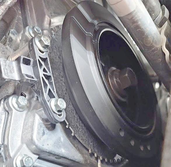


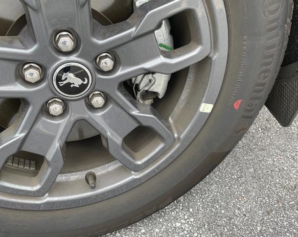
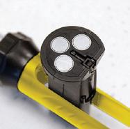
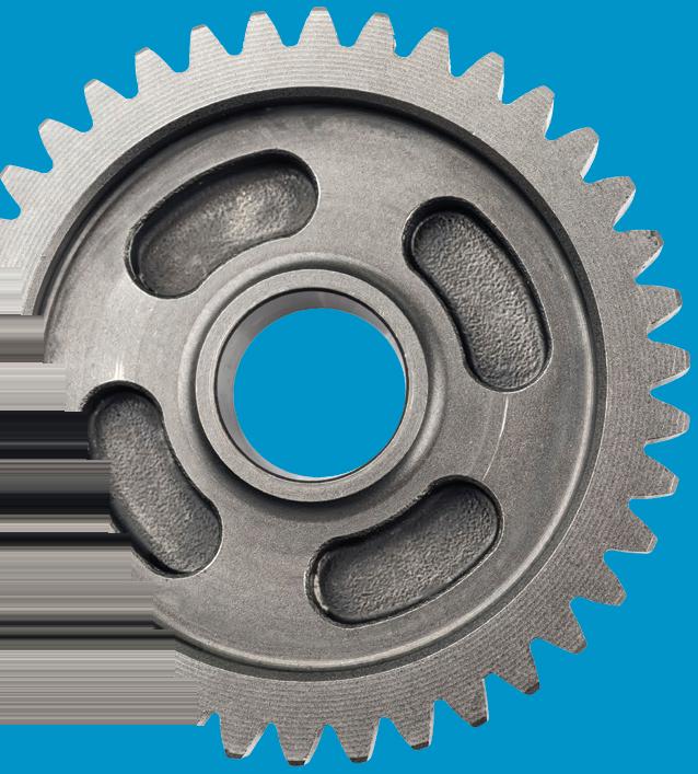
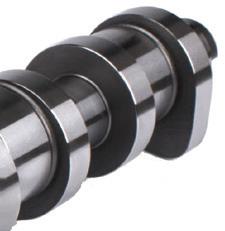
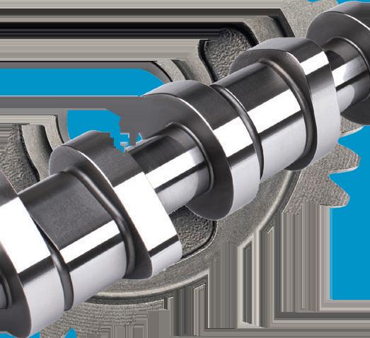
THIS IS the crank pulley from a 2024 Ford Escape Hybrid. There is no drive belt; the engine has an electric water pump and electric A/C compressor.
Their advanced design ensures a comfortable, quiet cabin, enhancing the driving experience and making them essential in modern electric and hybrid vehicles.

SCAN TO READ MORE OF JEFF TAYLOR’S ARTICLES.

JEFF TAYLOR is a seasoned professional at CARS Inc. in Oshawa with 40 years in the automotive industry. As a skilled technical writer and training developer, he holds licenses in both automotive and heavy-duty vehicle repair. Jeff excels in TAC support, technical training, troubleshooting, and shaping the future of automotive expertise.

Since 1923, we’ve been making filters that meet the quality of workmanship from professionals like you. And, they’ve only gotten better.


PurolatorTECH™ Oil Filters
• Designed for Optimum Oil Flow
• Rugged Internal Construction
• 96.5% Dirt Removal Power™

PurolatorTECH Air Filters
• Enhanced Engine Airflow
• Multi-Fiber, High-Density Media
• Trap More Debris Than Economy Filters

PurolatorTECH Cabin Air Filters
• Optimize HVAC and Defroster Performance
• Available in Particulate or Carbon
• Meet or Exceed Manufacturer Requirements
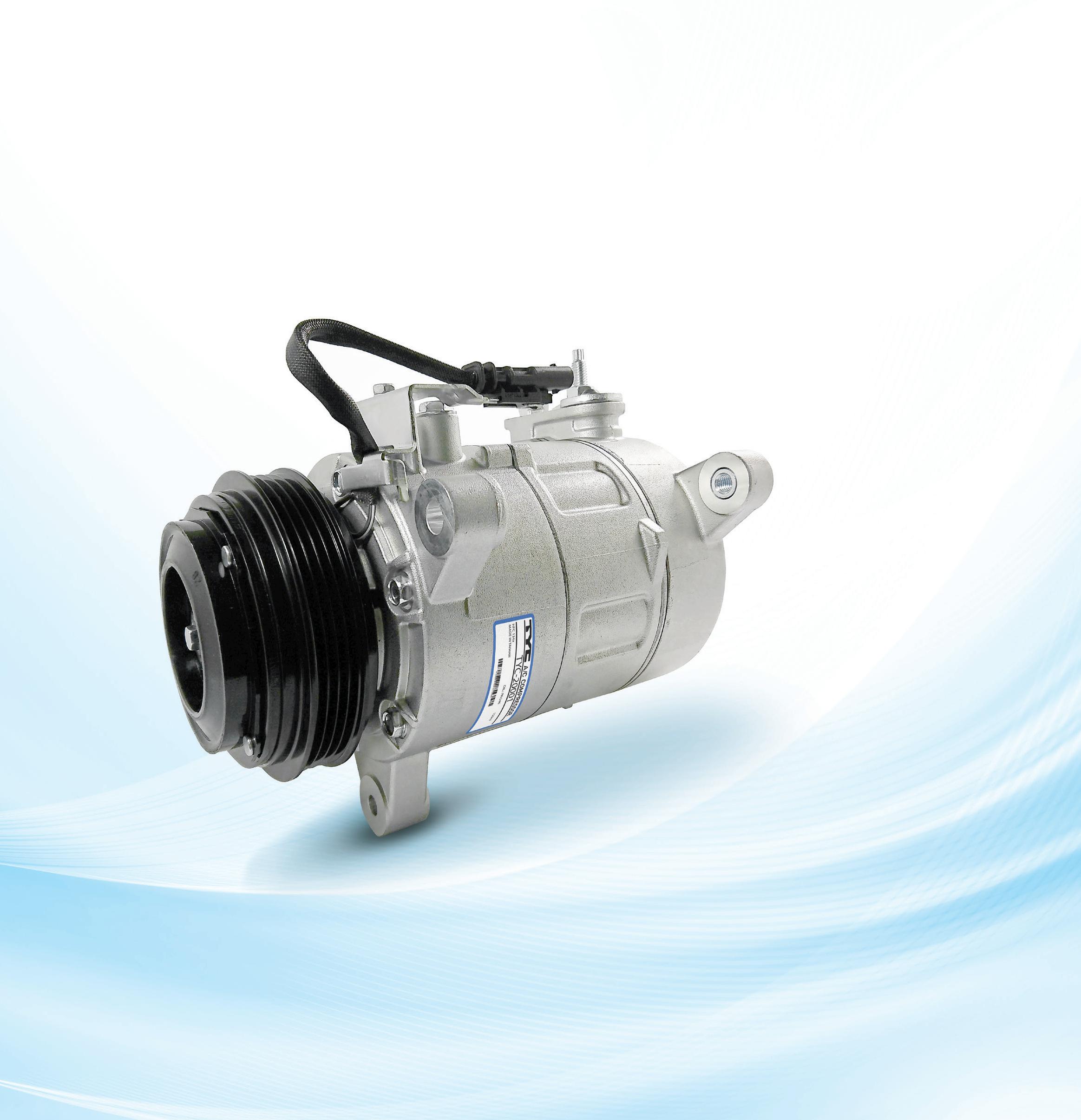
All-new, no-core AC Compressor program from TYC provides the highest quality without the hassle of managing core returns.
5
2
Precision manufactured on an extensively automated production line with strict QC control, TYC AC Compressors combine quality, reliability, and durability.
3
Manufactured in an ISO and IAFT-16949 OE-certified facility, each component is manufactured to exacting tolerances, assembled with precision, and prefilled with the appropriate PAG oil.
4
TYC AC Compressors are tested for durability, cooling performance, noise, Pulse Wave Modulation, and vibration to guarantee direct fit, function, and reliable performance.
TYC offers our customers nationwide distribution from five distribution centers, excellent service, and competitive pricing.
For more information about TYC Americas replacement automotive parts, contact your local TYC Americas Account Executive or look up parts online at www.tycamericas.com
TYC’s AC Compressor line removes our customers’ pain points of inconsistent quality and the hassle of managing cores. With an all-new, no-core program, TYC provides the solution to shop efficiency and fewer comebacks with our consistent quality and durability. Let TYC be your one-stop shop for your HVAC and Compressor needs and feel the difference our commitment to quality makes.


Many times driveability symptoms surface without associated DTCs. I find working backwards from the symptoms serves me best.
BY BRANDON STECKLER // Technical Editor
“THE
DOESN’T LIE,”


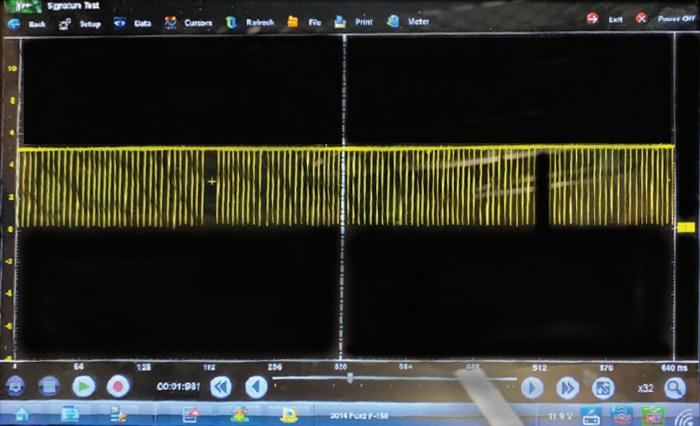
JUST A FEW months ago I spoke with my friend Clay Cowell of CMC Diesel in Big Timber, Mont., for the first time. He was faced with a 2013 Ford F150, with a 3.5L engine that exhibited a symptom of “Crank/No-start.”
Clay diligently pursued the issue but found himself a bit turned around, considering the PCM offered no DTCs as a clue to begin the diagnostic journey. The vehicle was driven flawlessly off-road and crossed a shallow creek before the engine stalled suddenly and wouldn’t restart.
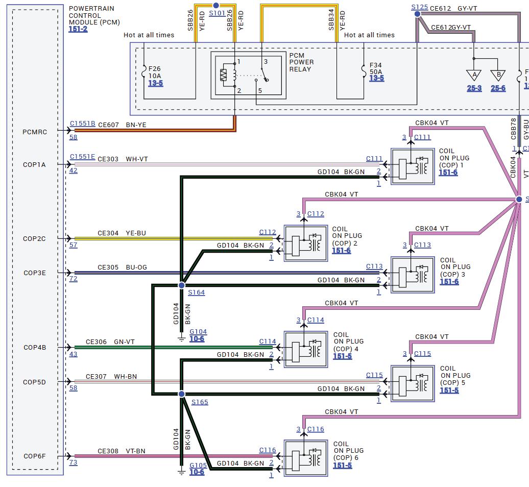
Clay reached out to me and told me of the situation. I suggested we begin determining what does seem to be functioning correctly. With that, Clay informed me that as the vehicle cranked, none of the ignition coils or fuel injectors were firing. I then told him of my tactic to always get to the root cause of either of the symptoms. I do this by asking “why” until I simply can’t find the answer to that question any further. So, I suggested Clay find out “why” a spark is not present, and what is required to create spark from a coil on this specific vehicle. Clay realized the ignition system utilized a 3-wire COP configuration for each of the six cylinders (Figure 1). Using his Snap-on Zues 4-trace lab scope, he then verified the COPs had adequate voltage and ground supply present, but the PCM failed to issue a command to fire the coils. Again, the question is, “Why?”

Armed with this knowledge we discussed that the PCM is not a smart device but is one that follows directions quite well. The PCM requires input from the timing signals (Crankshaft and/or camshaft position sensor signals) to decide when to fire the ignition coils and fuel injectors. My suggestion was to capture the signals to ensure they were not only present but reached the appropriate ampli-
FIGURE 1: THIS THREE-WIRE COP ignition system is a common configuration among gasoline internal combustion engines today. Being familiar with their functionality streamlines the diagnostic process.
tude and perhaps even correlated with one another properly.
Analyzing the captured CKP signal and comparing it to a known-good capture, I was suspicious of what appeared to be a missing pulse.
Looking at a trend view of the

data revealed that this missing pulse happened once per crankshaft rotation (Figure 2).
With all the information in front of us, and the desired information not yet obtained,

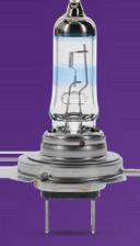
Delivering up to 130% more nighttime vision compared to standard halogen bulbs, Philips NightGuide platinum premium upgrade headlight bulbs give drivers more time to react for safer driving.
Make sure you’re stocked with the right product for lighting season.


Suspect-vehicle CKP waveform
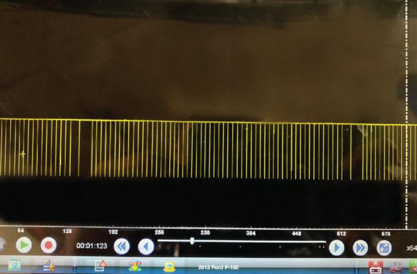
Known-good CKP waveform
we are faced with deciding how to proceed. Here are some bullet points of what we know to be factual, and I will ask all of you, diligent readers, for your input:
• The PCM will not fire the ignition coils or fuel injectors.
• No DTCs are present or pending.
• The COPs each receive adequate voltage and ground supply, but no triggered command.
• The CKP signal is present, of proper amplitude, but exhibits an anomaly.
Given this information, what would you do next?
• Replace the CKP sensor.
• Inspect CKP reluctor with borescope.
• Replace damaged crankshaft.
• Update PCM software.
BE SURE TO READ OCTOBER’S MOTOR AGE FOR THE ANSWER TO THIS MONTH’S CHALLENGE AND WHAT WAS DISCOVERED!


BY BRANDON STECKLER // Technical Editor
What would you recommend doing next, given the data bullet points in last month’s challenge?
Given this information, what would you do next?
1. Reset camshaft timing and re-evaluate.
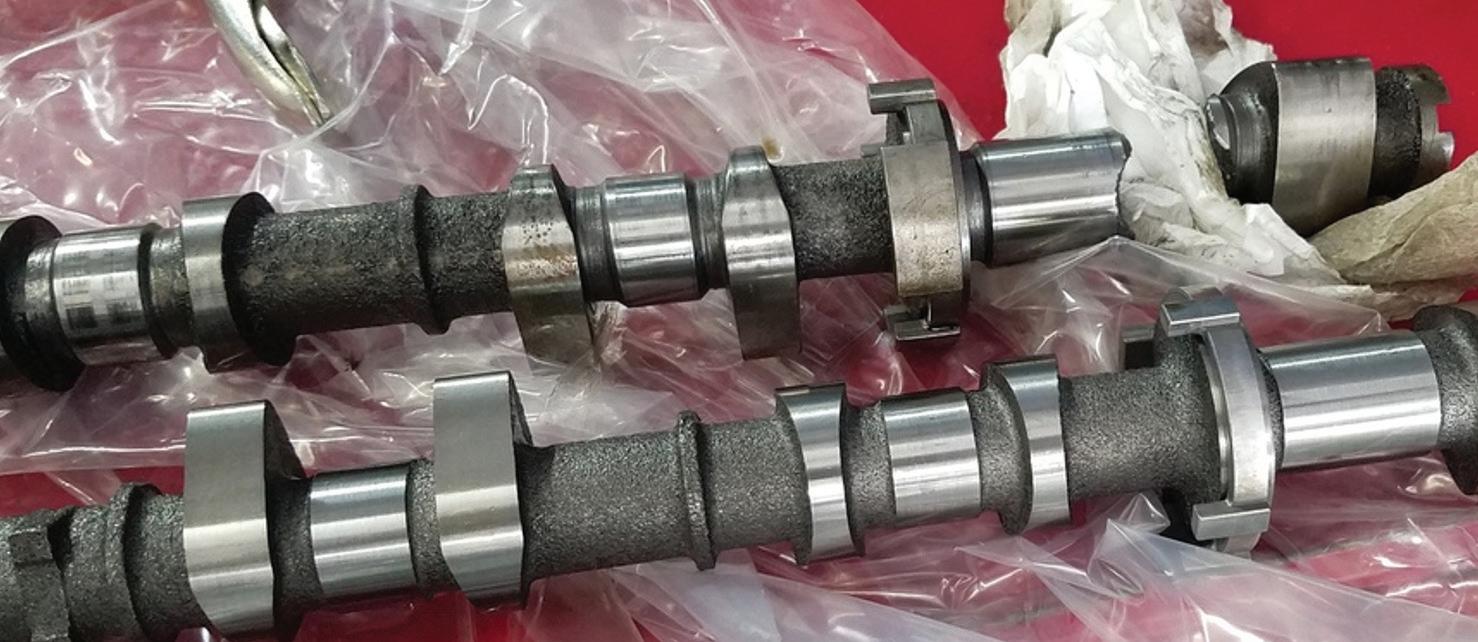
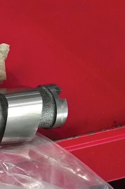
2. Inspect camshaft/pump condition.
3. Condemn FVR (HPFP assembly).
4. Condemn HPFP piston/chamber (HPFP assembly).


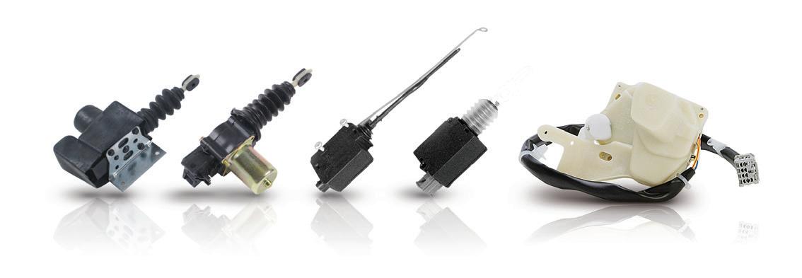
Continental door system components come ready-toinstall, right out of the box. We offer window lifts, motors, and assemblies as well as door lock actuators. Made in ISO Certified facilities, they provide exact OE fit, function, and performance for simplified installation and no comebacks.
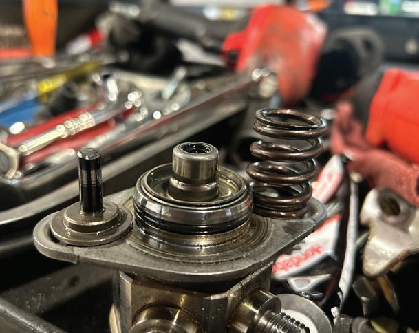
AFTER JUSTIFIED REMOVAL OF the HPFP for visual inspection, a broken camshaft pump drive was discovered. The cam was replaced and the vehicle was repaired.
For those of you who chose answer No. 2, congratulations! Answer No. 1 is incorrect. Even though cam timing has a drastic effect on HPFP output, the late intake cam timing would’ve yielded higher-than-commanded rail pressure.
Answer No. 3 is incorrect as the FVR has been proven to be functional through voltage and amperage testing. Replacing the FVR (HPFP assembly) would make no change to the symptom or data collected.
The answer could certainly be a possible fault and the likely cause of the zero HPFP-output. However, we cannot condemn the HPFP until visual inspection of the cam lobes and pump drive has been made.
The HPFP was removed, and the intake camshaft was found to be broken at the pump drive cam lobes, preventing the HPFP piston from stroking.

SCAN TO READ MORE ARTICLES LIKE THIS

BRANDON STECKLER is the technical editor of Motor Age magazine. He holds multiple ASE certifications. He is an active instructor and provides telephone and live technical support, as well as private training, for technicians all across the world.
6/27/24 2:07 PM


What once was known as HVAC is so much more.
BY CRAIG VAN BATENBURG
HVAC (HEATING, VENTILATION, and air conditioning) has been used to describe what happens in the cabin to keep people comfortable while driving. We need to stop using that term and rename it “thermal management,” but that sounds too much like engineering. The truth is you are an engineer, albeit without a degree.
On my business card it says “Craig Van Batenburg, DMM”. That is not a reference to a Digital Multi Meter. DMM in this context is “Doctor of Moving Metal.”
Don’t sell yourself short as you study these new EMVs (any vehicle with a high voltage drive system). These systems require the basic understanding of engineering, physics, and other subjects that many of us avoided in school so we could work “with our hands.” I enjoy “working” on mechanical things, but our brains must have critical thinking skills to figure out what went wrong. To do that, we must understand the systems.
When discussing heating, ventilation, and air conditioning in an EMV it takes on a whole new meaning. Not only are we using HVAC to cool or warm people and pets, it also plays a big part, either directly or indirectly, in keeping the HV battery, inverter, DC-DC converter, HV battery charger, fuel cell, electric motors, and other systems operating in a safe and efficient temperature zone. This article will explain the cooling and heating system’s “construction and function,” plus some unusual thermal systems used in EMVs.
The traditional heater, according to our research, was invented by an American named Margaret A. Wilcox, who was born in Chicago in 1838. It was patented on Nov. 28, 1893. Wilcox’s patent directed air from over the engine for warming the passengers in the 19th century. This led to using coolant not long afterwards. Using
wasted energy is smart. Wasting energy is not. As we all know an internal combustion engine (ICE) creates more heat than needed, so “free” heat was always a plus for any ICE-driven vehicle. I owned a 1959 VW Bus (Figure 4 on page 46). The ICE was air cooled and the heater was a joke. It was a very cold ride in the winter. All ICE vehicles are liquid cooled, so heating those vehicles is easy.
When the first Prius was sold in Japan in 1997 (as a M/Y 1998), the heating system for passengers was pretty simple. The original Prius added a bypass hose with a 12-volt coolant pump that was controlled by the HVAC ECU. Once the heat was turned on by the driver, the ICE would stay on until the coolant temperature reached about 180 degrees Fahrenheit and then “idle stop” was enabled. If the Prius driver set the climate control to 72 degrees, the HVAC ECU would communicate with the Hybrid ECU and if the HV battery was over 50% SOC, the ICE would shut off at a stop. The 12-volt coolant pump would be turned on and hot coolant would now circulate in and out of the heater core with the in-line pump. The ICE used a belt-driven water pump when the ICE was running. Many techs have asked us what happens to the
cabin heat when the ICE is in idle stop? The answer can be found with a scan tool. Here are the questions you need to answer:
• What is the reading of the ICE coolant temperature sensor?
• What is the SOC of the HV battery pack?
• At what SOC will the ECU restart the ICE?
• How much coolant temperature loss was there before the ICE restarted?
• Why did the ICE restart? SOC or cooling down during idle stop?
Once you have answered those questions you can come to some conclusions.
A plug-in hybrid has a more complex heating system than a hybrid vehicle. In order for a PHEV to function as an EV for short distances, the cabin heating does not use the waste heat from the ICE as the engine is not running. Some clarification here. Some PHEVs, like the Chevy Volt, have a powerful drive motor (111kW) and do not need the ICE at higher speeds or loads. The early Volt is classified as a PHEV or an EVER, depending on its mode of operation. Other PHEVs, like the first Prius PHEV, had a drive motor half the size of the Volt. To keep up with fast moving traffic, the ICE will start when the driver presses the “Go” pedal all the way down. Most PHEVs rely on the ICE even when the HV battery pack has sufficient charge to power the


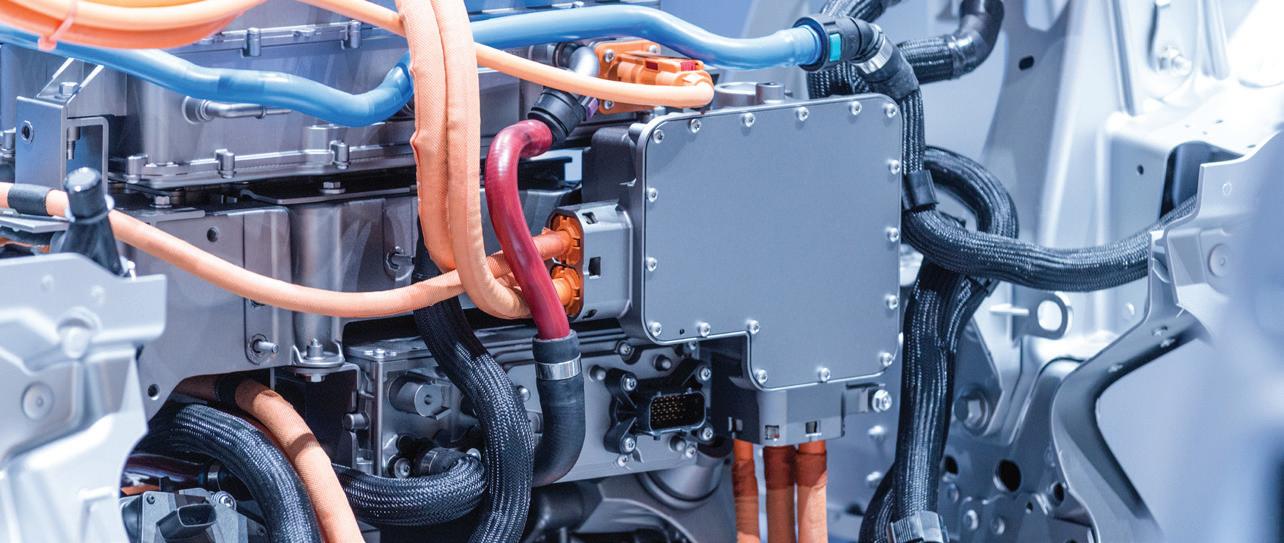
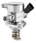
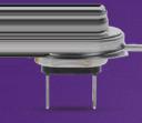
PHEV. When PHEVs first came to market in North America, they all bought the same HV heater (Figure 1) from a German company, with various attachment points and connectors. To provide cabin heat, a 1-gallon container (ACDC estimate) of coolant was heated using the high voltage battery for power, and that hot coolant was circulated in and out of the heater core with a 12-volt pump. The Chevy Volt had a decreased driving range of 30% to 40% in cold weather, as the heater was using the only energy on-board, the HV battery pack. That old-fashioned technology was also used in the Ford Fusion/C-Max Plugins called Energi. The load on the battery was 5 to 7 kW.
To stay warm is a human desire and many early PHEV owners used the heated seats and heated steering wheel, while wearing a jacket, hat and gloves, to stay warm with the heat off or on low to gain more range. That was not the solution most drivers wanted!
The original Chevy Volt started the ICE at 25 degrees regardless of the HVAC setting. Even if the driver kept the heat off, the PCM commanded the ICE on to use the warm coolant in the ICE and a “mixing valve” would add the warmed ICE coolant with the separate cabin heater coolant. Drivers complained to GM and a few years later the driver had the ability to have the ICE stay off until it reached 15 degrees, but then the ICE would start, even if the battery pack was fully charged. Once the SOC of the HV battery was at a pre-determined low level (usually 20% SOC or less), the ICE would start and the waste heat of the combustion process would provide all the free heat required.

FIGURE 1: WHEN PHEVS first came to market in North America, they all bought the same HV heater from a German company, with various attachment points and connectors. To provide cabin heat, a 1-gallon container (ACDC estimate) of coolant was heated using the high voltage battery for power, and that hot coolant was circulated in and out of the heater core with a 12-volt pump.


On the first generation of the Chevy Volt M/Y 2011-2015, the engine cooling system and cabin heater worked together (Figure 2).
It had an ICE radiator (No. 1), surge tank (No. 2), a 12-volt electric coolant heater pump (No. 3), high voltage (HV) coolant heater (No. 4), a cabin-mounted heater core (No. 5), a coolant flow bypass valve (No. 6), belt-driven water pump (No. 7), an ICE (No. 8) and a thermostat (No. 9). The ICE coolant flow bypass valve is controlled by the Hybrid Powertrain Control Module (HPCM2) to assist in regulating the cabin HVAC system, based on the availability of engine heat from the ICE. The coolant bypass valve separates the ICE and the cabin heater coolant loops to prevent heat generated by the HV coolant cabin heater from losing its heat into the ICE coolant system when driving in EV mode. The coolant flow bypass valve has two positions. When the ICE is OFF (as during electric-only EV operation) the valve is commanded to be in ICE bypass mode, shown as Position “A.” This permits the electric pump to circulate coolant through the HV heater then through the heater core in a short, efficient loop. For maximum electrical efficiency, feedback from temperature sensors in the passenger compartment and heater coolant loop are used to determine the necessary amount of electric current applied to the HV battery heating element which is an integral part of the Coolant Heater Control Module (CHCM). After the ICE starts up, in extended range mode for instance, additional ICE heat will soon become available to assist the HV coolant cabin heater in warming the passengers. At that point, the flow control valve is commanded to the “linked” position, shown as position “B,” and the two coolant loops are then connected. This parallel connection permits the sharing of coolant between the ICE and heater core, and subsequently the HV battery heating element (CHCM) power level will be reduced and/or cycled
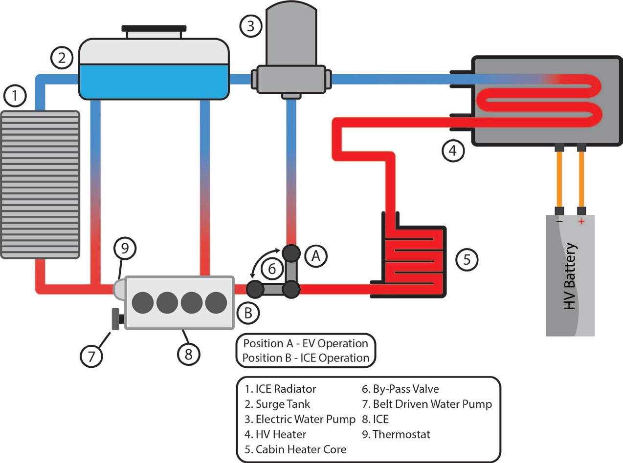
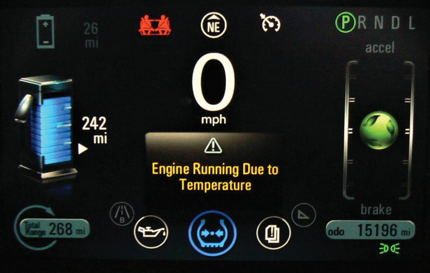
OFF/ON as the ICE turns on/off during extended range (charge-sustaining mode) operation in order to keep the cabin warm. The ACDC Chevy Volt (Figure 3) shows “Engine Running Due to Temperature.” In this case the Volt has 26 miles left in EV mode, but the ICE is running to provide additional cabin heat. Whenever the ICE is ON, a conventional belt-driven water pump is used. The thermostat regulates the normal ICE operating temperatures in a conventional fashion, but can be heated electrically to speed opening and
regulate flow. The thermostat creates a flow restriction for the ICE cooling loop that promotes a positive coolant flow and helps to limit air cavitation. When the ICE is first started and the thermostat remains closed, a hot water bypass hose permits heated coolant flow to the electric pump and heater core. Once the thermostat opens, flow will be permitted through the radiator which will maximize cooling yet still allow flow through


AAPEX is the ultimate destination for automotive aftermarket professionals from around the world. Here, you’ll do more than discover the cutting-edge products and solutions transforming the industry — you’ll see them come to life. From hands-on training and live vehicle demos to expert insights on new-to-market tools, shop management, and emerging trends and tech, you’ll have access to everything you need to navigate the winding road ahead. Join your community in Las Vegas at AAPEX 2024.
IS NOW OPEN. | AAPEXSHOW.COM
the heater core loop for cabin heating. This system is complex and not easy to service, but the idea was to get the maximum range from a small battery pack in cold weather.
When the first modern electric vehicles came to market, the Mitsubishi i-MiEV (Figure 5) and the Nissan Leaf, the old-fashioned technology of heating the cabin by warming coolant the way a PHEV did, lasted just a few years. Nissan, in M/Y 2013, came out with a “heat pump” in the SL and SV trim levels of the Leaf. This improvement in cabin heating reduced the load on the battery from 5-7 kW to 2 kW, for the same amount of heat. This allowed the EV to go farther on a charge while keeping the occupants comfortable.


5: WHEN THE modern electric vehicles came to market, the Mitsubishi i-MiEV and the Nissan Leaf, the old-fashioned technology of heating the cabin by warming coolant the way a PHEV did, lasted just a few years. Nissan, in M/Y 2013, came out with a heat pump in their SL and SV trim level Leafs. This improvement in cabin heating reduced the load on the battery from 5-7 kW to 2 kW.


How does a heat pump work? In simple terms, the condenser and evaporator change places by adding another expansion valve before the condenser. Then more tubing was added to bypass each expansion valve and the computer, depending on a request for heating or cooling, used one expansion valve or the other. In this way the heat is then produced in the cabin as you try to cool the air outside the vehicle.
Heat pumps have been used in buildings since the 1940s, but the concept goes back to the mid-1850s. When Nissan installed their version of a “heat pump,”
it was not used on the base model. At mid-year in 2013 the Leaf “S” had the heat pump. A couple years after Nissan added the heat pump to the Leaf, Kia added a “tweak” to make it more efficient. Toyota (Denso) then improved it again the next year.
Why all the improvements so fast? Consumers wanted more range in cold weather.
As we move away from the belt-driven compressor and more waste heat from internal combustion engines, a new landscape will emerge. Heat from a high voltage pack after the EV is shut off can be

FIGURE 4: 1959 VW was air cooled. The heat system was less than desirable. Liquid cooled internal combustion engines provided an easy way to provide cabin heat.

used to keep the cabin warm. A refrigerant cooling system can be used along with a liquid cooling system to move heat and cold around the EV where it is the most useful. Rather than add a high voltage grid under the dash, the electric drive motors can be run in a less efficient manner to make waste heat to warm the cabin on a cold day. That and more is being done today to not only keep the passengers in a climate-controlled cockpit, but also make the best use of the electricity that charges up the vehicle. Good thermal management of the electric vehicle is also good management for our earth.

CRAIG VAN Batenburg is the CEO of ACDC, a hybrid and plug-in training company based in Worcester, Mass. ACDC has been offering high voltage classes since 2000, when the Honda Insight came to the USA. When EVs were introduced in 2011, ACDC added them to their classes. Reach Craig via email at Craig@ fixhybrid.com or call him at (508) 826-4546. Find ACDC at www.FIXHYBRID.com.


Looking for battery performance under the toughest conditions? Install an FVP. Reliable, powerful – it’s the preferred battery of the NHRA. FVP. Reach for what works. POWER TO SPARE.


• We create videos for YOU, the automotive technician.
• Motor Age teaches you the “why” and not just the “how to”.
• You can trust the professionals at Motor Age to provide you with high-quality, engaging content!
Stay up-to-date on all new video launches - Subscribe here


“The Trainer” - Our Popular Monthly Series for The Professional Technician


Mastering Vehicle Diagnostics with Brandon Steckler


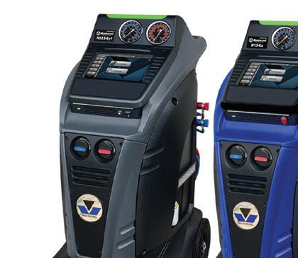
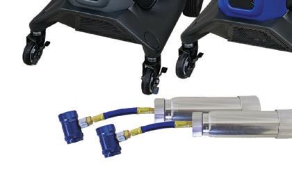

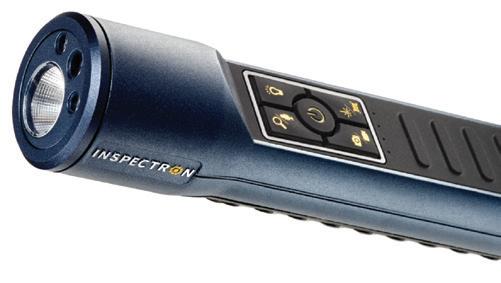

The Mastercool Arctic Commander 2.0 RRR Machines focus on intuitive design, elevated efficiency, and improved performance to set a higher standard. Experience effortless navigation with the spacious 10” color touchscreen command center. These units will recover 98.5 percent of the refrigerant in a vehicle which exceeds the SAE standards for purity and is the fastest in the industry. Rigorous ETL testing demonstrates an astonishing accuracy level, with desired charge and recovery quantities achieved with an impressive 1-gram deviation. The RRR Combo Kit includes a COMMANDER2100, a COMMANDER4100, and two free refillable universal dye injectors.

The Snap-on 500lm Dual-Sided Mini Flex Light, No. ECARL032R, features a 270 degree rotating design, multiple magnets, and provides technicians with unparalleled flexibility in lighting difficult-to-reach areas. Offering a 500lm dual-sided output, individual switches for spotlight and bar lights, and a dimmable switch with memory, this light caters to varying lighting needs. The integrated battery gauge enhances efficiency for technicians on the go.
The Inspectron WiTorch is the first HD video flashlight designed to improve service and inspection processes. It combines barcode, QR code, and OCR readers with the ability to capture pictures and videos. The WiTorch has been designed for operations in a wide variety of use cases where mobility in harsh and dark industrial environments is required. Its Wi-Fi capabilities connect the device seamlessly to the network in wide shop floors. It accelerates inspections and workflows when used in conjunction with Inspectron’s WiCollab app, compatible with Windows and Android devices.


The 6-Drawer and 4-Drawer Tool Carts from SK Tools are 35” steel tool carts with a durable powder-coat finish. They feature deep drawers with liners, double slides to provide more capacity and a full extension with soft-close. The carts come with an internal prybar and screwdriver racks, pegboards on the sides for additional storage space, and an integrated power station to keep charged. Four heavy duty swivel casters with locking brakes can hold up to 770 lbs. A central locking system allows access to drawers even when the lid is in the closed position.

The Sellars Absorbent Materials TOOLBOX WaterWeave T500 is a multipurpose wipe that is solvent-resistant and contaminant-free, and combines strength, durability, and absorbency. These wipes can be used to clean equipment and handle maintenance and repair jobs. The hydro-entangled substrate retains its strength, even when wet, so it can also be used on rough surfaces when wet or dry. Additionally, the WaterWeave T500 is a low-linting and latex-free product that can soak up oil and solvents, as well as clean dirt and grime from surfaces without leaving particles behind. Since the wipes are contaminant-free, they are a safer alternative to laundered rental shop towels and cloth rags.


The Mac Tools Angled Wire Crimper/Cutter/ Stripper, No. WSC8B, are multi-functional pliers designed to crimp, cut, strip, and grip, with a long nose, and 100-degree angled head design to provide access in tight areas. The pliers feature flat and round serrated gripping zones, which can strip stranded 12-22 AWG wire and crimp 12-22 AWG bare and insulated terminals. A nickel plating provides corrosion resistance. The pliers are available in three different colors: red, orange, and green.
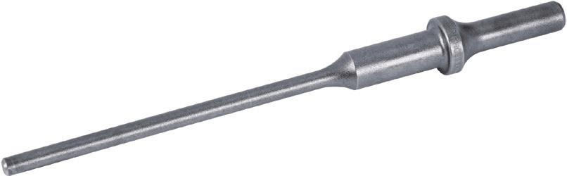
specifically for removing seized brake pins in various Toyota trucks and SUVs. This punch allows the vibration of an air hammer to be directed to the heads of seized brake pins to break them loose and drive them free to breeze through service and routing brake maintenance. Manufactured from heat-treated alloy steel, this American-made tool offers durability while removing brake pins in Toyota, Tacoma, Tundra, Sequoia, and 4Runner model vehicles.
The Tire Wrench Support Stand, No. 967, from Thexton is a steel support stand that includes multiple support points, ensuring alignment. The stand is 29.5” and is designed to provide clearance for various vehicles, from cars to heavy duty trucks. This stand is an aid in a technician’s arsenal for basic application to working on harmonic balancers. The stand’s construction allows for users to break it down for easy storage. Additionally, the stand accepts wrenches or extensions up to 1-1/4” in diameter.
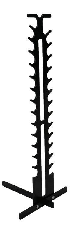

The Ledlenser AF4R Work Area Light delivers up to 2,000 lm, offers five brightness levels, and five-step tunable white light. With the Multi-Concentrated Light technology, the area light provides efficient directed light, maximum illuminance, and reduced glaring. Designed with hybrid power, users can use either the rechargeable battery or opt to plug-in with AC power. The light is protected from dust and water at an IP67 rating and offers flexible mounting options such as the foldable stand, magnet, or hook. At 2,000 lm the light has a runtime of two hours while at 200 lm the light has a runtime of 20 hours.


The 2-in-1 40” Z-Frame Folding Creeper, No. W85018, from Performance Tool, converts from a creeper to a rolling seat for automotive and shop needs. Fully padded cushions create a comfortable surface for laying flat or sitting upright, and six shielded 2” swivel casters allow for easy 360-degree movement and added stability. The creeper mode offers a low profile design that provides improved clearance, with dimensions at 40” by 16-7/8” by 5-1/8”, and a 300-lb capacity. The rolling seat size is 20-1/2” by 16-3/4” by 16-7/8” and has a 286-lb capacity. The locking pin in the seat configuration prevents unwanted movement and retracts easily for quick conversion.


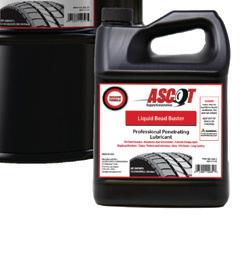
The Ascot Supply Liquid Bead Buster is a multi-purpose shop product that penetrates, lubricates, cleans, and protects most metal surfaces. It quickly dissolves and loosens rust, corrosion, and scale. This Bead Buster is non-flammable and non-combustible and is most commonly used as a commercial truck tire bead breaker, and available in many tub sizes.

The Martins Industries Impulse 1/2” Cordless Impact Wrench, No. MX-P1, features a maximum breakaway torque of 796.6 ft-lbs for a maximum speed of up to 2,400,1,900, and 1,500 rpms. The MX-P1 utilizes a forward/reverse button and a three-speed push button switch to easily increase speeds. It has a built-in LED worklight and an ergonomic handle.

The Autel MaxiTPMS TS900 is a 3-in-1 TPMS, diagnostics, and service tablet. Activate, read, and relearn all known TPMS sensors, including Tesla OE sensors, and program the Autel 1-Sensor to replace 99 percent of the TPMS sensors on the road today. The TS900 is also compatible with the Autel BLE Sensor, preprogrammed for Tesla vehicles. The TS900 offers both basic and advanced all-systems diagnostics and can generate, print, and share pre- and post-scans.
Heavy duty pliers used to remove and install the large internal retaining ring in transmission cases
Straight .120" diameter interchangeable tips
26" handles provide the leverage needed to compress large retaining rings


COURTESY OF MITCHELL 1

Here’s a tip from Lincoln. 2013-2018 MKZ hybrid vehicles using SOBDM-C module connectors do not require electrical/dielectric grease. If grease is applied, it may induce module communication concerns. DTCs U0293 and P0AA6 may be set. (Photo: Lincoln)
This bulletin specifically applies to 2016-2020 Infiniti Q50 and 20172020 Q60 vehicles equipped with a V6 engine, but also applies to engine oil drain plug cautions on any vehicle.

Over-tightening the oil drain plug can result in oil leaks and damage to the female threads in the pan.
Whenever installing an engine oil drain plug on the afore-mentioned Infiniti vehicles, never tighten the drain plug greater than the specified torque value. Over-tightening may loosen the threaded insert in the oil pan. Also, always replace the drain plug gasket whenever installing the drain plug. Instead of the oil pan drain plug hole featuring integral threads, the oil pans in these vehicles feature a threaded insert. Over-tightening can loosen the threaded insert, allowing it to spin in its hole. Proper drain plug tightening torque value is 25 ft-lbs (33.5 Nm).
(Photo: Infiniti)
RAM
This bulletin applies to 2013-2023
RAM 1500 vehicles equipped with a 3.6L V6 24V VVT engine. The MIL may be on. Technicians may find DTC P2072 (electronic throttle control system, ice blockage); P2110 (electronic throttle control forced limited rpm) and/or P2118 (electronic throttle control motor current performance Bank 1). The engine may not start in below-freez-
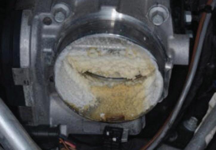
ing conditions (minus 20 degrees Fahrenheit). The throttle body blade is icing up.
Warm the vehicle indoors. Remove the air cleaner resonator, clean and dry any water or ice. Clean out and dry any water or ice from the throttle body. Install the air cleaner resonator. Remove the PCV valve/hose and clean out any water or ice. Install the PCV valve and hose.
Remove and discard the original make-up air hose and air cleaner lid. Replace with kit P/N 68631360AA. Also, replace the air filter P/N 68441763AA and engine oil filter 68191349AC and replace engine oil using six quarts of 5W20 oil.
(Photo: Mitchell 1)


This bulletin applies to 2016-2017 Volvo XC90, 2017 S90/V90/V90CC and 2018 S90 vehicles. The blind spot information system (BLIS) may not work and a text window and warning symbol message may be seen. This affects SODL/SODR (side object detection left/right) and SOD (side object detection). If a warning message “BITS system service required” occurs in the DIM together with DTC S0DR-U023292 and/or SODL-U023392 software, perform an upgrade to the software according to TJ31543. (Photo: Volvo)

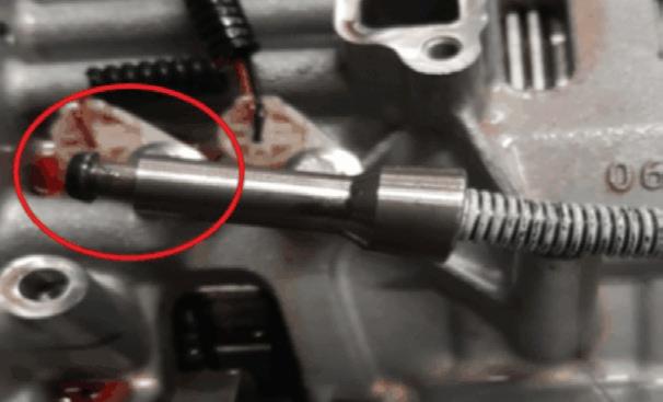
This bulletin applies to 2016-2019 Cadillac ATS, 2016-2018 CT6, 2016-2019 CTS and 2015-2018 Escalade vehicles equipped with an 8L45 or 8L90 automatic transmission.
Customers may comment that the vehicle will not obtain Park at times. This condition may be caused by a damaged parking pawl and/or parking pawl actuator.
The transmission may have experienced a Park engagement while the
vehicle was in motion or the transfer case obtained a neutral state.
Attempt to duplicate the No Park condition by operating the shift lever. The shift lever should move freely through all positions. Check the transfer case for proper operation in each range. Inspect the shift cable system and mounting bracket for any signs of visible damage or mis-routing.
Remove the transmission oil pan and valve body. Remove the park pawl actuator bracket and discard the bolts.
Remove the park pawl actuator. Inspect for damage, bent rod or incomplete travel of the actuator. Inspect the park pawl for damage.
If damage to the park pawl actuator and/or park pawl is present, replace the following:
• Park pawl actuator
• Park pawl
• Main shaft detent lever hub pin
• Park pawl actuator bracket
• Park pawl actuator bracket bolts
• Output carrier
Note: the transmission should be disassembled and cleaned thoroughly. (Photo: Mitchell 1)
This bulletin applies to 2018 Mazda6, 2017-2018 CX-5 and 2018 CX-9 vehicles, all equipped with MRCC Stop and Go function. Some customers may complain about a message on the driver display: “Mazda Radar Cruise Control disabled under 20 mph.” The forward sensing camera (FSC) cannot detect target objects due to dirty windshield, fogger FSC camera lens,

low visibility due to rain, fog or snow, insufficient light at night, direct or reflected sunlight on the SC, problem with the FSC, problem with the Autohold control function or problem with the electric parking brake.
Check for DTCs and address/repair as needed. If no related DTCs are present, no repairs are needed. Simply clean the windshield and front radar sensor. (Photo: Mitchell 1)
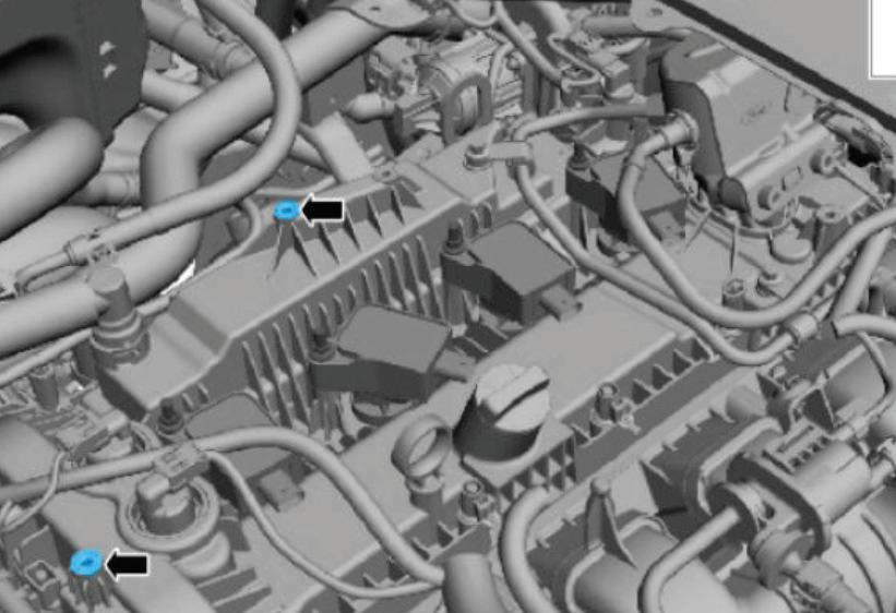
Some 2019-2022 Ford Ranger vehicles may exhibit a MIL on with DTC P0300, P0301, P0302, P0303, P0304 and/or P0316 stored in the PCM. This may be due to water buildup in the spark plug wells and corrosion on ignition system components. This may be the result of the engine appearance cover not being installed. Locate the two engine appearance cover mounting bosses on the valve cover. Make sure


that the engine appearance cover stud bolts are installed to the valve cover. Tighten these to 89 in-lb.
Lubricate each grommet on the engine cover with silicone brake caliper grease and dielectric compound to aid in cover installation. Install the engine cover. Install the two stud nuts and torque to 89 in-lb. The engine appearance cover kit is available as P/N L1MZ-6A949-C. (Photo: Mitchell 1)
This bulletin applies to 2019-2020 Genesis vehicles, where DTC U0109/ U010900 is stored and there is a communication error with the fuel pump control module (FPCM).
• Connect GDS to the data link connector.
• If there are any FPCM DTC related codes, replace the FPCM.
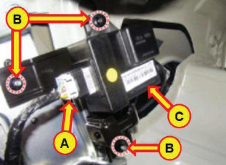
• Using a voltmeter, check the fuel pressure sensor (FPS) output voltage, Specified voltage is 5V.
• Check FPS output voltage at idle. Specified idle voltage is 1.4-3.2V.
• Test fuel pressure at the delivery line from the fuel tank. If FPCM is out of spec, replace the FPCM.
To replace the FPCM, turn ignition off and disconnect the battery negative cable. Remove the trunk rear transverse trim. Fold the LH luggage side trim to access the FPCM.
Disconnect the FPCM connector and mounting nuts and remove the FPCM. Install the new FPCM in reverse order. (Photo: Mitchell 1)

This bulletin applies to 2020-2024 Chevy Silverado 2500HD/3500HD trucks equipped with an L5P or L8T
engine and MGM, MGU or MKM transmission. You may find transmission fluid leaking from the bellhousing inspection cover. This condition may be caused by the automatic transmission case front cover seal being rolled or damaged. According to GM, if the leak has been verified to be coming from the front cover seal, replace the automatic transmission case front cover seal P/N 24277112 and the torque converter fluid seal P/N 24293986.
(Photo: Chevrolet)

This bulletin applies to 2017-2018 Jaguar F-Pace vehicles. A rubbing noise from the vehicle front may be evident at slow speeds. This may be caused by a harmonic resonance from the right front halfshaft support bracket. An updated bracket is available as P/N T4A29627. (Photo: Jaguar)


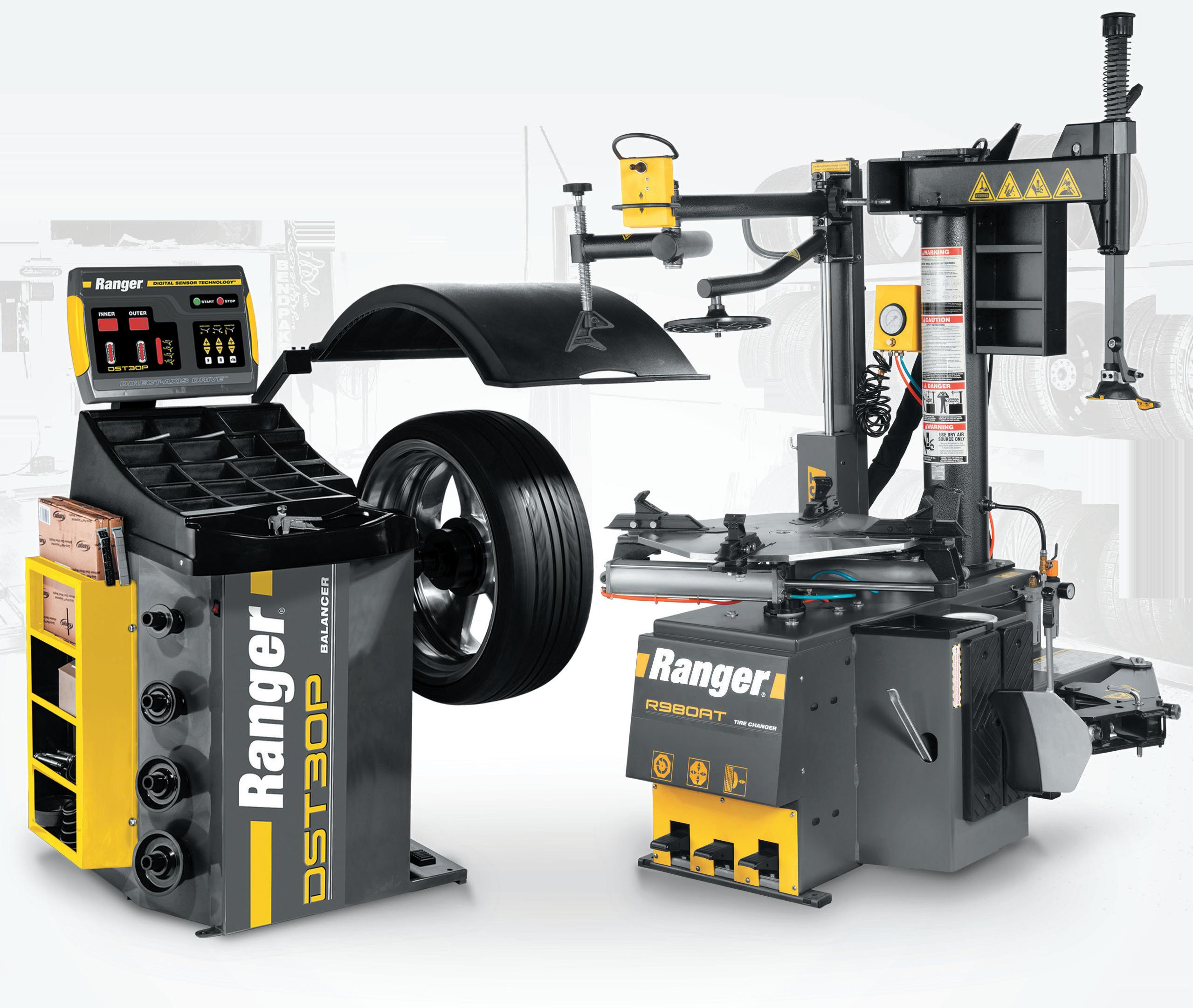


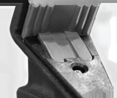


BY BRANDON STECKLER // Technical Editor
LET’S WALK THROUGH AN EASY AND EFFICIENT, CONFIdence-building approach to discovering gasoline direct injection (GDI) driveability symptoms.
Last month, Motor Age Technical Editor Brandon Steckler showed us his tried-and-true approach to symptoms exhibited in conventional, port fuel injection systems. All those tools and techniques still hold true regarding GDI systems. However, the layers of complexity and system strategies grew and changed with the implementation of the technology.
Using the acronym “AFAD,” this is the diagnostic process Brandon follows:
• Air measurement
• Fuel delivery
• Adaptive strategies
• Default strategies
As described in another recent episode of The Trainer (using graphed PIDs), this video evaluates each area of concern one at a time. The point is a lean-condition symptom (on a 2014 BMW V8
engine) seemingly related to a misreporting air mass meter was caused by a lack of fuel supply.
The PCM protected the vehicle from the lean condition. Not by increasing fuel delivery (via fuel trim) but instead by closing the throttle. The vehicle’s poor performance was not due to the cause of the issue, but the effect of that issue.
The AFAD systematic approach ruled out what simply could not be wrong with the vehicle. This left only potential faults with the low-side fuel delivery system to be further investigated.
In this episode of The Trainer you can learn the same systematic approach Brandon uses in the bay to preliminarily discover what area the fault lies in. All of this is conducted right from the driver’s seat and without any wasted time under the hood or beneath the vehicle.

FOLLOW MOTOR AGE MAGAZINE ON YOUTUBE TO SEE NEW VIDEOS AS THEY ARE RELEASED.


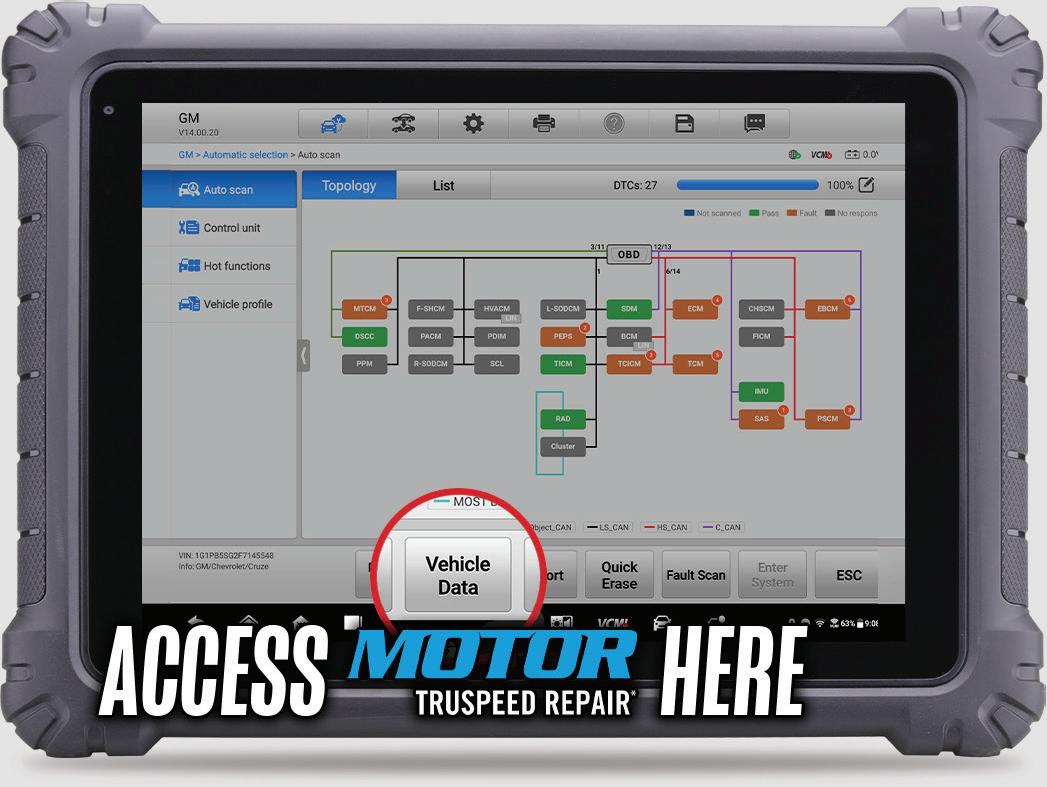


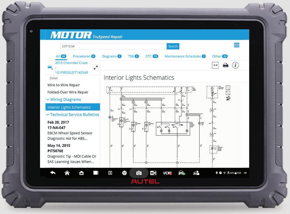

Evolve your technical skills for the future with training from Worldpac Training Institute® .