

Tips for Getting the Most Out of Your DMM
these practical steps to get correct readings from your digital multimeter every time. Read more on pg. 34


FLEX YOUR SAVINGS with Liquid-Tuff™ Custom Cuts
Discover the ultimate solution for your repetitive job needs with Liquid-Tuff™ Custom Cuts from Atkore. Factory-cut and deburred conduits that simplify installation, reduce time spent on each job, and maximize schedule certainty, especially for large repetitive quantities of 500 pieces or more.


From homes to prison cells, the modular and panelized construction market is booming. Here’s how it differs in building design, job-site workflow, and


ECMWEB.COM
With its exclusive online content, ecmweb.com is a valuable source of industry insight for electrical professionals. Here’s a sample of what you can find on our site right now:

SHOULD NOT ABANDON NATIONAL ELECTRICAL SAFETY REQUIREMENTS
National Electrical Code Todd Sims from NEMA explains why the path to making new homes more affordable should not come at the expense of eliminating electrical safety requirements. ecmweb.com/55270514

EC&M ON AIR — THE MOST MEMORABLE EC&M CONTENT OF 2024 WITH THE EC&M EDITORS
Podcast The EC&M editors discuss our readers’ most popular articles, videos, podcasts, and social media posts from last year. ecmweb.com/55270396

FEDERAL PROJECT LABOR AGREEMENT MANDATE AT RISK Construction In this Members Only article, Tom Zind looks at a recent court ruling that telegraphs an end to the year-old project labor agreement (PLA) requirement. ecmweb.com/55270123
Editorial
Group Editorial Director - Buildings & Construction: Michael Eby, meby@endeavorb2b.com
Editor-in-Chief: Ellen Parson, eparson@endeavorb2b.com
Managing Editor: Ellie Coggins, ecoggins@endeavorb2b.com
Editor: Michael Morris, mmorris@endeavorb2b.com
Art Director: David Eckhart, deckhart@endeavorb2b.com
Consultants and Contributors
NEC Consultant: Mike Holt, mike@mikeholt.com
NEC Consultant: Russ LeBlanc, russ@russleblanc.net
Sales and Marketing
VP/Market Leader - Buildings & Construction: Mike Hellmann, mhellmann@endeavorb2b.com
Regional/Territory Account Manager: David Sevin, dsevin@endeavorb2b.com
Regional/Territory Account Manager: Jay Thompson, jthompson@endeavorb2b.com
Regional/Territory Key Account Manager: Ellyn Fishman, efishman@endeavorb2b.com
Media Account Executive – Classifieds/Inside Sales: Steve Suarez, ssuarez@endeavorb2b.com
Production and Circulation
Production Manager: Josh Troutman, jtroutman@endeavorb2b.com
Ad Services Manager: Deanna O’Byrne, dobyrne@endeavorb2b.com
User Marketing Manager: James Marinaccio, jmarinaccio@endeavorb2b.com
Endeavor Business Media, LLC
CEO: Chris Ferrell
CDO: Jacquie Niemiec
COO: Patrick Rains CRO: Paul Andrews
CMO: Amanda Landsaw CALO: Tracy Kane
EVP, Group Publisher – Buildings, Energy & Water: Mike Christian
Electrical Construction & Maintenance (USPS Permit 499-790, ISSN 1082-295X print, ISSN 2771-6384 online) is published monthly by Endeavor Business Media, LLC. 201 N. Main St 5th Floor, Fort Atkinson, WI 53538. Periodicals postage paid at Fort Atkinson, WI, and additional mailing offices. POSTMASTER: Send address changes to Electrical Construction & Maintenance, PO Box 3257, Northbrook, IL 60065-3257. SUBSCRIPTIONS: Publisher reserves the right to reject non-qualified subscriptions. Subscription prices: U.S. ($68.75 year); Canada/Mexico ($ 112.50); All other countries ($162.50). All subscriptions are payable in U.S. funds. Send subscription inquiries to Electrical Construction & Maintenance, PO Box 3257, Northbrook, IL 60065-3257. Customer service can be reached toll-free at 877-382-9187 or at electricalconstmaint@omeda.com for magazine subscription assistance or questions.
Printed in the USA. Copyright 2025 Endeavor Business Media, LLC. All rights reserved. No part of this publication may be reproduced or transmitted in any form or by any means, electronic or mechanical, including photocopies, recordings, or any information storage or retrieval system without permission from the publisher. Endeavor Business Media, LLC does not assume and hereby disclaims any liability to any person or company for any loss or damage caused by errors or omissions in the material herein, regardless of whether such errors result from negligence, accident, or any other cause whatsoever. The views and opinions in the articles herein are not to be taken as official expressions of the publishers, unless so stated. The publishers do not warrant either expressly or by implication, the factual accuracy of the articles herein, nor do they so warrant any views or opinions by the authors of said articles.
Reprints: Contact reprints@endeavorb2b.com to purchase custom reprints or e-prints of articles appearing in this publication.
Photocopies: Authorization to photocopy articles for internal corporate, personal, or instructional use may be obtained from the Copyright Clearance Center (CCC) at (978) 750-8400. Obtain further information at www.copyright.com.
Archives and Microform: This magazine is available for research and retrieval of selected archived articles from leading electronic databases and online search services, including Factiva, LexisNexis, and ProQuest.
Privacy Policy: Your privacy is a priority to us. For a detailed policy statement about privacy and information dissemination practices related to Endeavor Business Media products, please visit our website at www.endeavorbusinessmedia.com.
Please Note: The designations “National Electrical Code,” “NE Code,” and “NEC” refer to the National Electrical Code®, which is a registered trademark of the National Fire Protection Association.
Corporate Office: Endeavor Business Media,
ID
© Valiantsin Suprunovich | Dreamstime
ID 109058947 © Ratmaner | Dreamstime


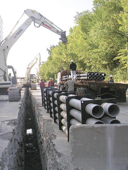
Assemble Conduit Above TrenchNo Workers BelowPrevents Injuries and Deaths. Also Allows Digging a Narrower Trench for Less: Excavation, Concrete, Slurry, Backfill & Shoring.


Electrical Industry Braces Amid Tariff Whiplash
By Ellen Parson, Editor-in-Chief

As I sat down to write this month’s viewpoint, I had several ideas floating around in my head. However, given the fact that this date coincided with the March 4 deadline for President Trump’s tariffs to go into effect on Mexico, Canada, and China, I couldn’t think of a more timely topic to cover in this editorial. Since the Trump Administration took office, this continues to be a fluid situation. Nevertheless, I think it’s important to ponder what these tariffs may mean for the electrical industry. Implemented on March 4 by President Trump as a measure to address national security concerns/combat drug trafficking and trade imbalances (in an effort to revitalize U.S. manufacturing and reduce trade deficits), the United States imposed a 25% tariff on most goods from Mexico and Canada (with energy exports from Canada facing a 10% tariff), and the existing 10% tariff on Chinese goods increased to 20%. Reciprocal tariffs on other countries will kick in on April 2. To set the stage for what many are calling a “trade war,” global tensions are definitely heating up because goods from China, Mexico, and Canada accounted for more than 40% of imports into the United States in 2024; these three countries are also the top three export markets for our country. What does all of this mean? I’m certainly no economist, but, depending on what source you’re citing, you’ll find the situation characterized as everything from a necessary means to safeguard American interests and level the playing field, revitalize domestic industries, and protect American jobs to economic suicide that will inevitably lead to increased inflation, higher interest rates, a risk of recession, increased consumer costs, and ongoing market volatility. According to a piece by Reuters (https://bit.ly/41RqZnP), “CEOs and economists say Trump’s tariffs on Canada and Mexico, covering more than $900 billion worth of annual U.S. imports, will deal a serious setback to the highly integrated North American economy.” Whether that will happen — and to what extent — is yet to be seen. How will the new trade policies affect the electrical construction market in terms of material prices (such as copper wiring and availability of electrical equipment like electrical panels, switchgear, and transformers to name a few), equipment lead time, and supply chain issues? The National Electrical Contractors Association (NECA) sent out an alert to its membership in early February, summarizing the immediate risks such tariffs could pose as well as offering strategies stakeholders should adopt to mitigate risks at ecmweb.com/55267362. The National Electrical Manufacturers Association (NEMA) issued a statement on March 5 from Debra Phillips, president and CEO, encouraging a long-term deal that strengthens trade across North America. “As the second largest U.S. exporter and second largest U.S. importer of manufactured goods, electrical manufacturers play a pivotal role in securing American energy independence and ensuring a secure and resilient grid — investing tens of billions of dollars in U.S. manufacturing and creating thousands of new jobs for American workers across the country,” she said in the statement (https://bit.ly/41sKJwl). “New trade policies must provide predictability and certainty for future domestic investments, allowing for a reasonable transition period for new large-scale manufacturing to come online and for supply chains to move.” As of press time (a few days after President Trump’s speech to Congress in which he admitted the tariffs may cause “a little disturbance”), the President had granted automakers a one-month exemption from the 25% tariffs on Mexico and Canada (as of March 5) on vehicles that comply with the United States-MexicoCanada Agreement (USMCA) free trade treaty. On March 6, he also announced a one-month tariff delay on all products from Mexico and Canada covered under the USMCA until April 2. Considering how many times the tariffs have changed in the last three days alone, by the time this print issue hits readers’ hands or the digital edition drops online, things could have changed many more times. After experiencing the whiplash of covering this breaking news story, I can’t help but wonder if this is truly about tariffs. Whatever agreement is ultimately reached on exact percentages of duties collected, deadline extensions, exemptions, or specific goods, the overall chaos and instability this atmosphere is creating — not to mention uncertainty in many of the vertical markets our audience serves — must, at least to some degree, be affecting electrical professionals when it comes to business planning, economic forecasting, and supply chain strategies. As this story continues to unfold, you can bet EC&M will bring you the latest updates and analysis.


WHERE FACILITY CHALLENGES FIND SOLUTIONS
CENTRAL VALLEY
March 19-20, 2025
Modesto Centre Plaza
Modesto, CA


SOUTHERN CALIFORNIA
April 16-17, 2025
Anaheim Convention Center Anaheim, CA
NORTHWEST
May 14-15, 2025
Oregon Convention Center Portland, OR
RENO
August 20-21, 2025
Grand Sierra Resort & Casino Reno, NV


15- or 20-amp, TR & TR/WR $6.00 each/$300 per case of 50 Purchase in bulk to receive additional
10 cases = 5% off 20 cases = 10% off 30 cases = 15% off 40 cases = 20% off 50 cases = 25% off
Vist


Warehouse Pick Up Price $19.55
Warehouse Pick Up Price $27.57
Price $32.57 2X4FT Panel
Product Features:
• Backlit technology that offers even lighting distribution without shadowing.
• Color selectability allows for changing between 3500K, 4000K or 5000K.
• Wattage/Lumen selectable versions: three different lumen outputs in the same product.
• Emergency battery back up optional.
• The range input voltage 120-277V.
• 125 lumens per watt -CRI>80
• DLC Premium/DLC Standard
Areas of Application
The backlit Panels are the high efficiency solution for offices, schools, hospitality and retail areas.
ELECTRICAL TESTING EDUCATION
Online Partial Discharge Detection and Location
How to determine the reliability of underground cables/ terminations and identify PD to prevent costly downtime
By Bharat Nandula, Qualitrol


Power cables are important assets in electric utility transmission networks for the reliable operation of power systems. To prevent catastrophic failures in underground cables and terminations, it is important to know how to leverage the various types of available sensors that can detect partial discharge (PD) and locate the source so that appropriate action can be taken to avoid in-service failures. This article answers questions about how technology can help identify partial discharge in underground cables without expensive shutdown time.
Power cable systems consist of the cables themselves and their accessories — joints and terminations. In recent years, the use of high-voltage (HV) power cables has increased due to more densely
populated urban areas and new power cables being installed in old networks.
New synthetic polymer materials have boosted the birth of extruded XLPE power cables, and the use of XLPE

insulation in HV cables is increasing due to its advantages: low dielectric losses, suitability for high operating temperatures, and relatively easy and low-cost manufacturing.
Electrical Testing Education articles are provided by the InterNational Electrical Testing Association (NETA), www. NETAworld.org. NETA was formed in 1972 to establish uniform testing procedures for electrical equipment and systems. Today the association accredits electrical testing companies; certifies electrical testing technicians; publishes the ANSI/NETA Standards for Acceptance Testing, Maintenance Testing, Commissioning, and the Certification of Electrical Test Technicians; and provides training through its annual conferences (PowerTest and EPIC — Electrical Power Innovations Conference) and its expansive library of educational resources.

Sparking at the termination point was visible, which could eventually break down the bushing connected to the cable.


ELECTRICAL TESTING EDUCATION
Online PD Measurement Sensors

A combination of HFCTs and TEV makes it possible to separate the signals that are coming from the switchgear panel, terminations, and cables.
Let’s address some key questions that arise around the topic of PD testing.
Q: How can you ensure the reliability and availability of cables that experience transients, lightning, or switching surges and fault voltages?
Electrical diagnostic tests have played a role, though this often involves expensive shutdowns and other cost implications. Most dielectric failures in HV XLPE cables are associated with defects in joints and terminations that develop over the lifetime of a cable system. To detect such changes at an early stage, detailed information on insulation condition is necessary. As an alternative to traditional diagnostic methods, this information can be achieved by PD monitoring during the operation of the equipment.
The most effective tool to detect local damage, defects, and/or localized aging processes in extruded cable systems is measuring PD. On-line PD measurements are most suitable
for detecting problems in cable terminations and joints. Harmful levels of PD can be detected well before a breakdown.
With continuous measurement, reliable estimations about insulation condition can be made.
Possible applications for online PD measurements are:
• Quality assurance of installed cables
• Continuous cable monitoring
• Location of problematic joints and terminations
• Prioritizing cable replacements
Q: What are the advantages of online PD monitoring over offline PD measurement?
Using PD technology has proven to be an excellent method to identify problems in insulation. IEC 60270, High-Voltage Test Techniques — Partial Discharge Measurements, details the most adaptive and conventional method of measuring PD. However, this method is most suitable for offline diagnostics in environments with less
electromagnetic interference. Since aging of the insulation of in-service HV components is ongoing, on-site PD testing and diagnosis have attracted increased interest for use in condition monitoring. Since conventional PD measuring systems used in a controlled factory environment are not generally suitable for on-site application, specialized PD detection and measurement methods have been introduced.
PD signals can be detected by unconventional PD measuring methods and systems that use the physical characteristics and properties of the PD processes. These methods have gained significant popularity as they can be applied while equipment is operating. For example, unconventional PD coupling methods based on inductive or capacitive sensors have led to increased sensitivity at the accessories (joints) compared to conventional PD detection at the cable end. One promising approach is the use of inductive PD sensors at terminations and cross-bonding the links of long HV cable systems.
Fig. 1.
SNAP2IT® CONNECTORS

Snap connector onto installed MC cable.
Arlington’s new one-piece RETROFIT SNAP2IT® fittings are easy to use in an OLD WORK installation, and handle the widest variety of cables! They’re ideal for adding additional circuits to a load center. And you get the same labor-savings in a retrofit installation!
Easy snap-in installation - NO TOOLS. Install connector into the knockout in an existing box, pulling cable/conduit through the knockout. Slip the fitting onto the cable, then snap the assembly into the box. That’s it... a secure installation with no pullout

Widest total cable ranges 14/2 to 10/3
Widest variety of cables AC, MC, HCF, MC continuous corrugated aluminum cable, MCI-A cables (steel and aluminum), AC90,


Arlington’s non-metallic Split Wall Plates provide a simple and effective way to accommodate pre-connectorized low voltage cable(s) of varying size and quantity or pre-existing low voltage cables.
Multiple split grommets are provided with our single- and two-gang wall plates for increased versatility in effectively sizing and covering the hole/opening.
Use as shipped, or with one of the supplied bushings to alter the size of the opening.
• Single-gang CESP1 w/ 1-1/2" opening, bushings for .312" • .500" • 1" openings

• Two-gang CESP2 w/ 2" opening, bushings for .750" • 1.250" openings 1-1/


ELECTRICAL TESTING EDUCATION


MRO Insider
This e-newsletter, published monthly, serves electrical engineers, plant managers, maintenance engineers, facility and energy managers, maintenance supervisors, electricians, and technicians who work in industrial, commercial, and institutional facilities.
Topics covered include:
• Maintenance, repair, and operations
• National Electrical Code on the production floor
• Safety procedures and programs
Subscribe Today
See all of our EC&M e-newsletters at www.ecmweb.com
Cable PD Portable System
USB link to laptop to acquire data, analyze and generate reports
Transponder receives small PD pulses from one HFCT and injects a high magnitude pulse back into the cable
Several advanced software techniques and hardware solutions are useful for discriminating between actual PDs and noise interferences.

Q: What type of sensors or sensing techniques are used in online PD testing?
To detect PD activity online, nonintrusive sensors must be used. For online PD detection, high-frequency current transformers (HFCTs) are used to detect current pulses from PD in the cables and switchgear. Transient earth voltage sensors (TEVs) are used to detect electromagnetic radiation from PD activity from terminations and switchgear. By using a combination of sensors, sensitivity to various types of PD can be obtained, and the measurements from different sensors can be correlated to aid in the diagnosis. A combination of HFCTs and TEV (Fig. 1 on page 14) makes it possible to separate the signals that are coming
Time (ns)
from the switchgear panel, terminations, and cables.
HFCT
The most suitable sensors for underground cable PD measurement are inductive-type HFCTs. These sensors can be installed when the cables are in use (i.e., energized). Typically, HFCTs are mounted on the ground straps of the MV or HV cable at the connection boxes. To design and select appropriate HFCTs for these applications, the lower and higher cut-off frequencies, polarity, and saturation characteristics must be considered. A lower cut-off frequency is an essential parameter for HFCTs. It’s a compromise between the ability to detect dispersed signals from long cables and tolerating noise pickup from mains. Most of the HFCTs on the market for lower
Fig. 3. Partial discharges were clearly evident during the testing cycle.
TEV sensor to detect external discharges
HFCT sensor to detect cable internal discharges
Other 2 HFCTs AC Supply
Long length of power cable
Plastic & Steel 8X10 TV BOX


Arlington’s 8X10 TV Box™ with a Plastic or Steel Box offers the ultimate in versatility for installing TVs in new and retrofit projects. There's more room in the box for wires and it installs horizontally or vertically to properly position low voltage connections behind the TV.
• Ideal for home theater systems: multiple connections for sound systems, satellite TV, CATV, DVRs
• Brackets for neater cables, with a 1-1/2" knockout for ENT and other low voltage wiring


• Box mounts to stud in new work; for retrofit, mounting wing screws secure


ROOF TOPPER® supports raise conduit/raceway 4" or more off the roof surface, allowing contractors to comply with the 2017 NEC® for temperature adjustment for circular conduit.
The heavy-duty base, made of 100% recycled material, sits on the roof deck. There’s no need to mount ROOF TOPPER to the surface with mechanical fasteners.


Offered in a variety of sizes and configurations, ROOF TOPPER supports up to 2000 lbs, and stands up to extreme rooftop conditions protecting and elevating conduit or raceway above the roof deck.


ELECTRICAL TESTING EDUCATION

cut-off frequencies operate in a range from 50 kHz to 150 kHz. For special applications where no dispersed signals need to be captured, much higherfrequency ranges can be used with the benefit of obtaining lower noise levels.
Higher cut-off frequencies — the maximum frequency at which an HFCT needs to respond — depend on the application. A high-frequency HFCT cut-off is generally 10 MHz or higher based on the application. The HFCT should be clearly marked in terms of its polarity relationship (e.g., an arrow pointing toward the grounding point of the cable or earthing strap). The orientation doesn’t seem to matter, but if more than one HFCT is used in a test and the polarity of the signals needs to be compared, a clear and common definition is needed.
TEV
Another type of sensor widely used in medium-voltage (MV) switchgear employs the transient earth voltage (TEV) phenomenon, which has been more widely exploited for condition monitoring and asset management of MV switchgear. Transient earth voltage sensors make use of the skin effect to measure electromagnetic radiation


due to internal partial discharge. This is an attractive sensing option because measurements are inherently safe and can be made without any physical intrusion or modification to the switchgear. The benefits of TEV measurement derive from the ability to
install sensors non-intrusively on inservice equipment.
Q: What are the possible approaches for monitoring PD? Two approaches can be used to perform online PD testing on cables: periodic
Fig. 4. Phase C clearly showed PD signals during testing.
Fig. 5. Observing Phase C and TEV activity in the time domain, it was clear that the PD activity was located at the termination end of the cable.
LISTED BOX EXTENDERS

Arlington’s variety of cULus Listed Box Extenders extend set back electrical boxes up to 1-1/2”.
Made of heavy-duty, 105°C continuous use 94V0 rated, flame retardant plastic, they level and support wiring devices, while protecting wires against damage and stripping.


Choose the one that’s right for you!
BE1, BE2, BE3, BE4...Single-, two-, three- and four-gang, and BE1R for round or octagonal boxes...
Box Extenders


device support in oversized or mis-cut wall openings, available in single-, two-, three- and four-gang, (patented BE1X, BE2X, BE3X, BE4X.)
Our new heavy duty, COMMERCIAL-GRADE steel support plate! As shipped, single and two-gang BE1XLS and BE2XLS work with maxi cover plates, but they’re and standard plates. Convenient. Saves time. Great for poorly cut drywall.

For all standard devices, switches and GFCIs, our box extenders comply with NEC Article 314.20 for set back boxes.


ELECTRICAL TESTING EDUCATION

Illumination Insider
This e-newsletter tracks the research, development, design, installation and operation of all types of lighting and control products.
This twice-a-month product is geared toward professionals working in the industrial, commercial, retail, residential, institutional, health care, government, and utility market sectors.
Subscribe Today
See all of our EC&M e-newsletters at www.ecmweb.com
monitoring and continuous monitoring. Periodic monitoring is reasonably immediate to deploy, with tests between a few minutes and a few hours per circuit.
Continuous online monitoring provides 24/7 monitoring and the ability to do trending. By trending this summary data, changes in PD activity during the monitoring session can be observed. For example, increases in PD magnitude indicate the defect is getting larger, and increases in PD count indicate defects are discharging more rapidly. When the activity meets pre-set event criteria, discharge magnitude levels, and discharge rate, the system can generate alarms.
Q: What is the greatest challenge in performing online PD measurement?
The greatest challenge in online PD measurement is distinguishing between actual PD signals and noise from various sources such as electromagnetic (EM) interferences, adjacent circuits, and corona when cables are connected to overhead lines. Several advanced software techniques and hardware solutions (Fig. 2 on page 16) are useful for discriminating between actual PDs and noise interferences.
In the following case study, capturing 50 non-consecutive cycles and all pulses in the time domain — while at the same time capturing the phase-resolved PD data — showed the data in different dimensions.
CASE STUDY
Periodic online monitoring was conducted on 3-phase, 268-m, single-core 33kV cables terminated to switchgear. The remote ends were terminated to a transformer. The PD monitoring system used HFCTs, TEV, and a portable measuring instrument. PD recording was performed at an MV metal-clad switchgear cable termination box. HFCTs were clamped around individual earth shields of power cables, and TEV sensors were attached to the inner walls of the switchgear cable termination enclosure.
Fifty non-consecutive cycles were recorded. With the help of software and algorithms like artificial intelligence (AI) and pulse shape analysis, the data was
divided into PD and non-PD categories, as shown in 4 on page 18.
The investigation further consid ered data including phase activity, pulse shapes, and phase-resolved PD com pared with TEV and HFCT graphs. Note that phase graphs were phase consistent, and pulse-shape graphs confirmed the PD source from Phase C.
The next task is to determine the loca tion of the partial discharges. Comparing the HFCT and TEV data indicated the same activity from both sensors. As this software and monitoring device can cap ture individual pulses, we further looked at data in the time domain. The same activity was observed in pulse-shape analysis graphs from the HFCT, which was installed on phase C, and the TEV sensor, which was placed on the panel.

Observing Phase C and TEV activity in the time domain ( was clear that the PD activity was located at the termination end. You can see that HFCT and TEV activity was occurring at the same time at a high magnitude.
When the terminations were opened a few months later, it was clear that there was sparking at the termination, which could eventually break down the bush ing connected to the cable (see on page 12).

CONCLUSION
Online PD measurement is an important technique for use on power cables and switchgear during routine inspection and after installation to assess the condition of equipment and prevent catastrophic failures. Implementing online periodic monitoring is an effective solution to avoid catastrophic failures. The case study explained how important it is to have time-domain measurements. Time-domain characteristics can be used to classify the signals, and the method of separation based on time characteristics and AI allows noise pulses and PD to be isolated.
Bharat Nandula is a technical application specialist at Qualitrol, where he serves as a technical resource on GIS, transformers, and high-voltage cable monitoring solutions for the company’s sales and product managers and end users.
MC CABLE FITTINGS


each fitting also comes with end stop bushings that accommodate different size cable bundles. ONE trade size fits SEVERAL cable types and sizes, plus flexible metal conduit for super convenience and cost-savings! Reduces inventory and material handling too.


Refer to spec sheet for specific end stop sizes Listed for FMC

6/3, 6/4, 4-3, 4-4, 8/3, 8/4, 6/3
2-3, 2-4, 1-3
2-3, 2-4, 1-3, 1-4, 6/3, 6/4, 4/3, 4/4, 3/3, 1/0-3, 1/0-4, 2/0-3, 3/4, 2/3, 2/4
2/0-4, 3/0-3
2/0-4, 3/0-3, 3/0-4, 2/4, 1/3, 1/4, 1/0-3
4/0-3, 4/0-4, 250-3, 250-4 1/0-4, 2/0-3
250-4, 300-4, 350-3, 2/0-3, 2/0-4, 3/0-3, 3/0-4, 350-4, 500-3 4/0-3, 4/0-4, 250-3
500-3, 500-4, 600-3 4/0-4, 250-3, 250-4, 300-3 600-4, 750-3 300-4, 350-3, 350-4, 500-3
600-4, 750-3, 750-4 350-4, 500-3, 500-4 750-3, 750-4, 1000-4 750-3, 750-4, 1000-3
MOTOR FACTS
Get to Know Your Electric Motors
Basic tips and information about electric motors to keep on hand
By Mike Howell, PE, EASA

Electric motors are critical assets in many applications, so access to nameplate ratings and terminal markings can save time and money as a motor is moved in and out of service for storage, maintenance, repair, or replacement. While there are many types of electric machines, this piece will focus on standard, 3-phase, squirrel cage induction machines. Most of these are built to NEMA or IEC standards, and most of their nameplate information is standardized.
NAMEPLATE INFORMATION
NEMA and IEC standards mandate that motor nameplates provide such details as the manufacturer’s name,
motor type, and frame designation. Manufacturers assign unique types to identify motor applications and specifications. Frame designations define standardized dimensions critical for mounting and coupling motors to driven equipment. This information is available in NEMA Std. MG 1 and IEC Std. 60072-1.
Motor nameplates generally include the rated power, base speed, voltage, frequency, and full-load current. This basic information is often documented by the end user either on schematics or in asset management systems. Other important characteristics like insulation class, ambient temperature, and duty type are often overlooked but the
two characteristics we’ll focus on here relate to starting current and accelerating torque.
STARTING CURRENT
The starting current, also known as locked-rotor current (LRA), may appear on the nameplate of NEMA motors, but usually, a NEMA code letter indicates a permissible range. IEC Std. 60034-12 limits locked rotor apparent power using design letters. When end-users procure replacement motors without considering this starting characteristic, starting problems often arise.
Newer machines built to higher efficiency standards generally have low-resistance rotor cages, which means


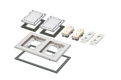
FLOOR BOX


(3) FLBC8500 boxes


a two-gang box. Add another for three-gang! FLBC8500 Single gang box


Single gang
FLBC8510BR Brown
FLBC8510BL Black
FLBC8510GY Gray
FLBC8510CA Caramel
FLBC8510LA Lt Almond
Two-gang
FLBC8520BR Brown
FLBC8520BL Black
FLBC8520GY Gray
FLBC8520CA Caramel
FLBC8520LA Lt Almond

Three-gang
FLBC8530BR Brown
FLBC8530BL Black
FLBC8530GY Gray
FLBC8530CA Caramel
FLBC8530LA Lt Almond


Build a two- or three-gang concrete floor box by simply locking single gang boxes together!
Then buy the UL LISTED single, two- or three-gang cover/frame kit, with devices included, in PLASTIC, FIVE COLORS – or in economical diecast zinc with a brass or nickel finish. Fast, easy installation.
Cover installs with hinge on either side.


Two-gang FLBC8520MB
Three-gang FLBC8530MB
(1) FLBC8530BL Black plastic cover/frame kit
FLBC8530MB
MOTOR FACTS
higher starting current. So, replacing an older kVA code G motor with a new kVA code J model could increase the starting current by as much as 43%. To some extent, this situation is unavoidable, but it can be anticipated, which helps when planning.
ACCELERATING TORQUE
The NEMA design letter specifies the torque profile as the motor accelerates to full speed direct-on-line at rated voltage and frequency (see Figure at right). Design B machines (the most common) are used in applications like pumps, fans, and blowers. Design C machines are usually found in applications like conveyors and crushers. High-inertia load applications like punch presses use Design D machines, often with a flywheel in the system. The rotor cage design determines the speed-torque curve profile, so a stator winding redesign cannot facilitate a design letter change. Trying to replace a Design C or Design D motor with a Design B motor because of availability is a common error that almost always results in rapid failure. IEC Std. 60034-12 defines the common IEC design letters N and H. The nameplate may indicate the motor’s design characteristics. Keeping a photo of each nameplate on file is useful when repairs or replacements are needed.
TERMINAL MARKINGS
NEMA Std. MG-1 and IEC Std. 60034-8 provide standardized terminal markings for 3-phase machines. It is important to retain documentation for the number of motor leads and how they are marked. A

C or H
A, B or N
NEMA speed-torque curves.
or part-winding. Machines designed for multiple speeds at power frequency by changing the external connection may have more than one winding as well. Service centers have reliable procedures for identifying and marking the leads of 6- and 9-lead machines, but they’re not trivial and can require special equipment not always available to the end-user. For this reason, the ser-
The bottom line: Having procedures in place to document and preserve the external connections can save time and prevent mistakes when motor repair or replacement is necessary.
3-lead machine is simple to connect to the power supply. It gets more complicated with 6-, 9- or 12-lead machines that may have several design configurations, including multiple voltages, multiple speeds, and special starters like wye-delta
vice center usually sends personnel to the site or transports the motor to the service center. It is difficult to identify and mark 12-lead machines without disassembly if most (or all) of the markings are gone.

The bottom line: Having procedures in place to document and preserve the external connections can save time and prevent mistakes when motor repair or replacement is necessary. If a service center rewinds a motor and changes the number of leads, be sure the change is well documented.
SUMMING IT UP
Including complete motor nameplate data and terminal marking information in your asset management system and ensuring that procedures are in place to preserve terminal markings on the motor are very simple ways to reduce downtime and streamline replacement should a machine need to be removed from service for repair or replacement.

Mike Howell is a technical support specialist at EASA in St. Louis. EASA is an international trade association of more than 1,700 electromechanical sales and service and repair firms in nearly 70 countries. Visit www.easa.org for more information.
Design B
Design
Design
EASYTHUMB SCREW ADJUSTMENT

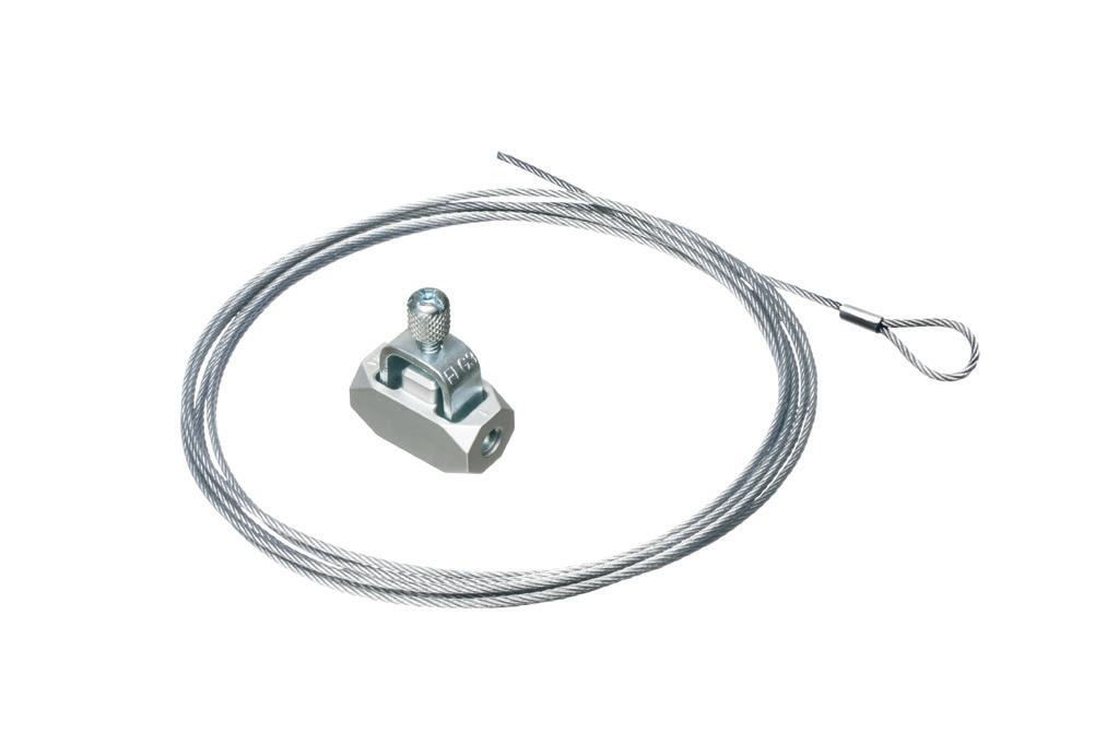


Here’s reliable hanging support for fixtures, fixture boxes, cable tray, high bay light fixtures and other static loads requiring drop wire support! Better than traditional wire-hanging methods, costs much less than competitive products.
• Screw engages six points of contact on wire – no internal spring
ONE Wire Grabber holds a static load up to 75 lbs;
• Easy length adjustment with thumb screw – no special tool
• Works in dry or wet locations; unaffected by oil or grease
• Connector ships fully assembled
Wire Grabber Kits
(Bulk wire available)
SINGLE LOOPED END
CATALOG WIRE NUMBER LENGTH
DWB0805 5'
DWB0812 10'
DWB0815 15'
DWB0820 20'
DWB0830 30'
”Y” w HOOKS ”Y” w TOGGLES
CATALOG WIRE NUMBER LENGTH
DWYH0805 5'
DWYH0810 10'
DWY2H0810 2 PK* 10'
DWYH0815 15'
DWYH0820 20'
DWYH0830 30'

CATALOG WIRE NUMBER LENGTH DWYT0805 5' DWYT0810 10'

DWY2T0810 2 PK* 10'
DWYT0815 15'
DWYT0820 20'
DWYT0830 30'
How to Make Safety Training Stick
It’s easy for details to get lost and concepts to be forgotten — so how can you fix this?
By Mark Lamendola, Electrical Consultant
The learning retention rate for safety training varies between abysmal and outstanding. This wide range means that in many organizations — and for many individuals — there is an excellent opportunity for improvement.
The less that is retained, the higher the risk of injury or death. It’s much better to be at or near the “outstanding” end of the spectrum rather than at the other end. So how do you get there?
TYPES OF RETENTION
With any kind of training, students experience two kinds of retention:
1. Immediate retention. Instruction is given. What does the student remember at its conclusion?
2. Retention over time. Knowledge degrades over time, so what you remember days or months after training is almost certainly going to be less than what you remember right after training.
If immediate retention is low, then retention over time will also be low. So one key to retention over time is to start with more that you can lose. Suppose in your organization the average loss after six months is 10%.
• If students retain 30% of the training at its conclusion, six months later they will retain 27%.
• If students retain 90% of the training at its conclusion, six months later they will retain 81%.
BOOSTING IMMEDIATE RETENTION
Here are some reasons immediate retention can suffer, and what to do for each one:

• Students are disengaged. This could be because the training is boring and/or the value of it has not been properly communicated. Start by emphasizing why the particular training matters. You can use visual aids such as injury photographs, or even have a guest speaker who suffered injury. For example, a Chicago-based electric utility had a lineman who had lost both arms speak on electrical safety, and those in attendance were fully engaged.
• Too much distraction. Have people shut off their phones. Make it clear they need to focus on the training. Reward them for this focus by keeping the training fairly short. Keeping it short
also helps them stay focused, because for most people, the “focus muscle” tires out after about 20 minutes.
• It’s treated as an afterthought. Is the training held after a long work day when people are tired with no real preparation? Schedule it at a time and in a place conducive to learning. Prepare for the session as if someone’s life counts on it (because that may very well be the case). Refuse to engage in “death by PowerPoint.”
• The material is poorly arranged. When training is divided topically — perhaps into modules — a student can more easily focus, more easily build on one point to understand another


Arlington’s steel SliderBar™ offers the easy, NEAT way to mount single or two-gang boxes between wood or metal studs with non-standard stud cavities.
No more cutting, nailing and fitting extra 2x4s to fill the space! SliderBar saves about 20 minutes per box. Designed for studs spaced 12” to 18” apart, SL18 allows positioning of one or more boxes anywhere in the stud cavity.
• Bending guides on bracket assure proper positioning on studs
• Interlocking tab stop prevents accidental disassembly
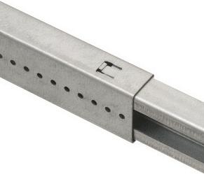


• Pre-punched pilot holes on BOTH sides of S for easy attachment of one or two boxes
SAFETY CORNER
point, and more easily remember information because (in a given session) it’s related.
• Too much detail at once. Break it down into digestible chunks. Focus a given session on one or two major concepts. Use as many sessions as you need rather than rushing to check off the box. Break the more complex topics into multiple sessions and revisit already covered topics (in brief) as you go through the series of sessions. It is better to sip from a glass than try to drink from a fire hose.
• The training is a boring lecture People learn best when they are interacting with the instructor. Get them involved by asking them questions, giving them problems or challenges to work out, and calling on individuals to ask questions or give comments on what was just said.
• Where applicable, require practical demonstrations. A practical demonstration allows the student to move understanding from the abstract to the real world. In the real world, the student’s other senses will also be brought to bear, and that is yet another way that learning sticks.
Reasons for low immediate retention can vary by subject, location, instructor, and individual. Identify the existence of low retention by giving a short quiz and/ or asking for a practical demonstration. Find the reason for low retention by asking students and instructors for their input. Use the input to improve the training. Then rinse and repeat with each subsequent session. Do this process with a teamwork attitude rather than an attitude of blaming someone. The idea is you work together to bring training retention as close to 100% as you can — regardless of who needs to make what adjustment or change.
BOOSTING RETENTION OVER TIME
One obvious way to boost retention over time is to conduct training more frequently. A word incorrectly used for this technique is “retraining,” but retraining means you repeat the training — and it does not connote frequency. Using a combination of both will yield superior results, especially if the retraining
is done with the idea you will cover the material but not aim it at the uninitiated. The way you retrain a previously trained person should differ from how you train a completely new person. The person being retrained already understands the concepts and principles but may have grown a bit fuzzy on the details.
Retraining on lockout/tagout, for example, doesn’t need as much time on concepts such as why lockout/tagout is important or on principles such as “always verify.” It doesn’t need as many examples to illustrate the typical workflow. Retraining might, however, entail new information (such as how to handle an atypical workflow based on something that actually happened in the plant).
Some other ways to boost retention over time:
• Hold to the standards. If people are trained to do things a certain way but in practice see them done to a lower standard, then that is the standard to which they will most likely drop. If you teach that a fall harness must be inspected before each use and people are not doing that, the training will not stick.
• Make people responsible for each other’s safety. This is a common practice in diving, climbing, and other dangerous endeavors. If you are charged with keeping your buddy safe, and it’s part of the way things are done, then you will be mentally rehearsing your safety training on a routine basis.
• Give people authority. It isn’t enough that every worker must have the authority to stop work if something or someone is not safe. They must have that authority if something just doesn’t seem safe. There’s often a reason for those prickly neck hairs or that nagging “I can’t put my finger on it” doubt. When those arise, the worker must have the authority to stop work and the responsibility to methodically address the issue. Maybe it’s nothing. Maybe it’s something. They can’t know until they check it out. As they check it out, that training kicks in and gets reinforced in their memory.
• Do random spot checks. For example, Mike and Jeff are performing a
lockout/tagout. So stop Mike and ask a question such as, “Once this breaker is locked out, I will know the circuit is dead, right?” Mike should respond in the negative, and then tell you that you don’t know it’s de-energized until you use a three-step verification process with a meter. If you get any other kind of response, rephrase the question.
• Address near misses. Why do near misses happen? It is not because people properly executed the work in the way they were trained to do it safely and they just had bad luck. It is because they made one or more safety mistakes and escaped injury due to good luck. It’s those mistakes that need to be identified. It’s unlikely a supervisor will witness a mistake as it happens, so how can this valuable information be shared and learned from? Establish a penaltyfree safety mistake reporting system. It can be an anonymous system similar to a suggestion box, or whatever people are comfortable with. But get that information to people so they learn from mistakes rather than die from them. Update both initial training and retraining accordingly.
BE SPECIFIC
While general safety awareness is never a bad idea, it is not sufficient for retaining the specific safety information that workers must use to perform their work. It’s often easier for managers and supervisors to rely on passive means because they never have to confront someone “who wasn’t doing anything wrong, he just forgot.” But when someone forgets, the consequences can be tragic.
Carl might be able to recite “Safety is no accident” due to having read it on the shop entry floor mat several times a day, but that’s not going to help him remember the correct way to do a voltage check versus another method that creates an ionization trail. If Carl’s workmate Julie sees him start to perform the voltage check the wrong way, she must have the authority and responsibility to stop Carl, address the problem, and report the near miss.
Mark Lamendola is an electrical consultant based in Merriam, Kan. He can be reached at mark@mindconnection.com.

Super-secure installation!
Our
L-shaped fan/fixture box mounts to single or double joists with a captive center screw. No loose parts!


screws ship captive, ready to install box and bracket. For

• Locator posts assure proper positioning of fan/fixture bracket


This convenient combo box has power and low voltage openings in the same box for a neat, time-saving installation.
The box adjusts to fit wall thicknesses from 1/4" to 1-1/2". Mounting wing screws hold it securely in place.
• 2-Hour Fire Rating
• Low voltage side has a combo 1/2" and 3/4" KO for raceway
• Includes NM cable connector (power side)


Designed for new work, Arlington’s non-metallic 20 cu inch FR series device and fixture boxes mount to a flat surface with NO NEED to cut an opening in the substrate.
Interchangeable backs and extension rings allow ONE box to work with almost any cladding system, including engineered foam and stucco systems.
Extra-wide flanges prevent water and air-intrusion, helping to meet the International Energy Conservation Code, and eliminating the need for gaskets or caulking.
Boxes install before or after the weather barrier house wrap. And ship ready for use with 1-3/8” finish/cladding thickness. Adjustable up to 1-7/8" for CUSTOM depths.


Troubleshooting Voltage Sags and Swells
Best practices for field technicians investigating power quality problems
By Jason Axelson, Fluke

Asteady supply of voltage is important in industrial and commercial applications to maintain equipment performance, product quality, and safety, while also minimizing downtime. Voltage sags (where the expected voltage dips 10% below the expected range) or swells (where voltage jumps 10% above the expected range) can cause problems throughout facilities. In this article, we’ll discuss steps to effectively troubleshoot voltage sags and swells.
WHAT ARE SYMPTOMS OF VOLTAGE SAGS OR SWELLS?
Voltage sags and swells manifest in many ways. Lighting circuits can be impacted, which workers may notice as annoying flickering or even lighting levels dropping to unsafe levels. Equipment with electronic power supplies may reset, and
processes requiring use of motors could fail or experience production errors due to loss in motor torque.
THE IMPACT OF VOLTAGE SAGS AND SWELLS ON PROCESSES AND COMPONENTS
Sensitive electronics operate using electronic power supplies that require peak voltages to be within an optimal range to operate properly. Voltages that are either too low or too high can damage power supplies or cause equipment to shut down, restart, or operate at reduced performance levels. While events of short duration tend to have less impact on system performance, longer events can impact power supply performance and prevent equipment from operating.
If problems with sags and swells aren’t addressed, out of warranty repairs could become common, decreasing
Courtesy of Fluke
GROUNDING BRIDGE
MULTIPLE ZINC


Arlington’s heavy-duty Grounding Bridges provide reliable intersystem bonding between power and communication grounding systems. And handle multiple hookups of communications systems: telephone, CATV and satellite.
Our new GB5T is THREADED for threaded conduit or another GB5T – with a SET SCREW for use on EMT or PVC.
Arlington’s zinc and bronze grounding bridges...
• Four termination points; more than required by the NEC
• Meet 2020 NEC bonding requirements for 250.94
• Fast, simple installation indoors or outside
• Textured, paintable plastic cover (except GB5NC)


• Easy access for inspections


INSIDE PQ

PQ Newsbeat
If you’re an engineer, commercial or industrial facility manager, or electric utility employee concerned about the quality and reliability of power delivery, this e-newsletter (sent out monthly) is for you.
Topics covered include:
• Power quality
• Voltage sags & swells
• Transients
• Harmonics
• Power factor
• Test & measurement techniques
Subscribe Today
See all of our EC&M e-newsletters at www.ecmweb.com
available capital for other products. Motors could also suffer reduced torque, decreasing energy efficiency and increasing utility costs.
WHAT CAUSES VOLTAGE SAGS AND SWELLS?
The most common causes of voltage sags are loads turning on. Voltage sags can also happen due to impedance problems, such as loose wiring or improper cable sizes for the load requirements.
Swells in voltage can be caused by loads on the system being turned off as well as by switches being activated or line to ground faults causing voltage swells.
HOW TO IDENTIFY VOLTAGE IRREGULARITIES
1. Interview all the stakeholders in the environment to document and understand the problems each individual is experiencing. This process helps avoid unnecessary investigation into the origin of the problem and helps determine if the problems are isolated to one particular area of the plant.
2. Once the location or locations of possible electrical problems have been identified, inspect the electrical panel for loose connections — either by using a thermal imager, visually, or by de-energizing and securing the panel to check proper torque. Correct any loose connections found.
3. Take simple meter measurements with an appropriately rated multimeter at panels and subpanels to confirm proper voltages.
4. If supply voltages are normal — and dips and swells are still occurring even after loose wires have been corrected — connect a power analyzer with recording capabilities to better understand what is going on with the electrical systems at all times of the day. Ideally, record for at least a week.
Power analyzers capture the ongoing voltage and current to help determine the cause or source of the problem. If both the current and voltage drop at the same time during a voltage sag, the cause of the voltage sag was most likely internal. If the current remains constant, the most likely cause of the sag is external.
While voltage swells occur less frequently, the power analyzer can still
help identify the source of the problem. Look for line-to-ground faults on single-phase lines, which can cause the voltage to suddenly swell on the two non-faulted phases.
HOW TO RESOLVE VOLTAGE IRREGULARITIES
1. Correct any loose connections and ensure proper grounding.
2. If voltage irregularities are still occurring, other mitigation options include installing suppressors, filters, isolation transformers, voltage regulators, or power line conditioners. An uninterruptible power supply (UPS) system is another option that employs different technologies to improve power. However, it comes at a higher capital cost.
3. After mitigation solutions are employed, ask operators and other stakeholders to keep a log to report any continuing problems. You can also continue using a power analyzer after fixes are in place to ensure power stability has been achieved.
CONCLUSION
Voltage sags and swells can cause prob lems in the short term as assets reset unexpectedly or production slows down. The long-term implications, including damage to assets and increased utility costs, can be even more costly.
Finding and correcting the root causes of voltage sags and swells is an important part of ensuring quality power supply in your facility. Address ing these issues reduces overall costs and increases uptime. Even if your plant isn’t currently experiencing symptoms of voltage sags or swells, performing power quality studies from time to time can help identify potential cor rective actions that not only improve equipment performance but also reduce energy consumption.
Jason Axelson is a product application specialist for Fluke. He has more than 15 years of experience helping custom ers and partners find solutions for power quality, scope meters, and battery testers. He also conducts application training to help diagnose and resolve both technical and product inquiries.


STEEL
SNAP2IT® CONNECTORS

TINTED 40STS

the cable into the connector and rotate it clockwise.
Available in 3/8" trade size, both connectors install into a 1/2" knockout, and are listed for steel and aluminum AC, HCF, MCI and MCI-A cable. The tinted 40STS has more room inside for easier cable insertion.

In Canada both connectors are Listed for use with AC90 and ACG90 cable.
• Tested to UL 514B and Listed to meet UL ground fault requirements
• Removable Unscrew the connector counterclockwise to remove it from the cable. Remove the connector from the box using a flat blade screwdriver. Release the snap tangs from the inside of the box while pulling the connector out of the knockout.
• Packed in heavy-duty, 200 piece boxes
CATALOG NUMBER CABLE RANGES STEEL Snap2It® connectors
38STS AC, HCF, MCI, MC!-A 14/2 w ground, 14/3, 14/2 12/2 w ground, 12/3, 12/2 • 10/2 w ground, 10/3, 10/2 .405” Dia. Minimum to .605” Dia. Maximum
40STS AC, HCF, MCI, MC!-A
Tinted 12/2 w ground, 12/3, 12/2 • 10/2 w ground, 10/3, 10/2 .480” Dia. Minimum to .605” Dia. Maximum
120A
38STS
By Randy Barnett, NTT Training
Tips for Getting the Most Out of Your DMM
Follow these practical steps to get correct readings every time.
Modern digital multimeters (DMMs) are user-friendly, accurate, and safe — when used correctly! Reading voltage is simple, but measurements must be properly interpreted. With a clamp-on DMM, accurate current flow readings are obtained if you follow the tricks of the trade. Resistance measurements are easy if you know what you are measuring
(see “Make Sure Your DMM Does What You Need It to Do,” below). Following are tips for measuring voltage, current, and resistance for safe and effective DMM use.
TIPS TO INTERPRET THE VOLTAGE MEASUREMENT
Follow all safety precautions, set up the DMM, and place the test leads on the test points. The number appearing on the meter face is the voltage difference
Make Sure Your DMM Does What You Need It to Do
Here’s a handy checklist to follow when using a digital multimeter (DMM).
Inspect the DMM, leads, and any accessories before each use.
Replace DMM batteries before use if a low battery indication is obtained.
Use a logging DMM to record data for later analysis and spot trends/sporadic problems.
For safety and convenience, use a wireless DMM to obtain measurements remotely from the equipment.
Consider a DMM with temperature, frequency, capacitance, milliamp, microamp, and other measurement capabilities if needed.
Use the diode test function rather than the resistance function to test the operability of electronic components with P-N junctions such as diodes, transistors, and LEDs.
Use the relative mode (REL) feature to indicate the difference between a stored value and the current value.
Use the min/max setting to capture events that occur in microseconds and would otherwise be lost.
Use intrinsically safe DMMs in hazardous locations.
between those two points. However, that number may not be what you think it is.
Set the DMM for the correct voltage.
A simple error is failing to set the meter function switch to the appropriate voltage type (AC or DC). Experienced techs will quickly catch their mistake and change to the switch. New technicians, while learning to use their meter, may just be confused and proceed in the wrong direction. Make sure you know whether the circuit is AC or DC, and set the meter accordingly.
Use a true-rms DMM (when applicable).
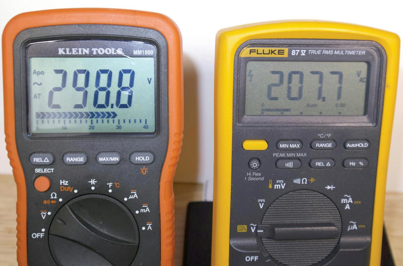
Reading voltage values in electronic circuits, such as variable-frequency drives (VFDs), uninterruptible power supply (UPS) systems, battery chargers, and any distribution system supplying significant electronic loads, requires the use of a “true-rms” meter rather than an “average-responding” DMM. An average responding meter reads the root mean square value (rms) of a pure sine wave. Due to the countless electronic devices in distribution systems today, many such systems are made up of distorted sine waves. These distorted waves can produce voltage readings as much as 40% low and high on average responding DMMs. Electronic loads produce high-frequency noise and harmonics that distort the non-sinusoidal readings. Low-pass filters are designed into DMMs to block high-frequency noise. Use the correct type of DMM on these circuits, or expect inaccurate readings (Photo 1 on page 36).
Be aware of voltage drop.
When measuring voltage values in distribution systems, do not expect to read nominal system voltage — the

voltage found on the transformer nameplate. Voltage drops due to long conductor runs and equipment operations occur. Intermittent problems and overheating may occur. If a coil in a relay or motor starter drops to approximately 70% to 80% of the rated voltage, the relay will continually drop and pick back up creating a chattering sound. Motors will tend to draw more current at lower voltages, creating overheating problems. Understand the concept and effects of voltage drop to effectively troubleshoot your system.
Watch for DMM loading in electronic circuits.
DMMs have high input impedance when set to voltage, thus preventing the meter from acting as a load on the circuit. While not a problem when reading distribution system voltages, measuring values in electronic circuits can be different. Modern DMMs generally have sufficient input impedance, preventing any appreciable amount of current flow through the DMM. Ensure the meter
meets the proper specifications when working with electronics.
TIPS FOR CLAMP-ON AMMETER USE
The clamp on the clamp-on DMM senses the strength of the magnetic field around a conductor created by current flow. Increasing current flow increases the strength of this field and thus an increased amperage reading on the meter. Grasping this basic concept helps us understand the tips for using the clamp-on DMM.
Clamp around only one wire.
The direction of the electromagnetic field developed around a conductor depends upon the direction of the current flow through the wire. The clamp on the DMM (whether a part of the meter design or an accessory for the meter) senses this magnetic field developed around the wire. As current flows through one conductor of a circuit, it returns on an opposite conductor. Thus, the magnetic fields developed around each of these conductors would be in
opposite directions. If both conductors are placed inside the clamp at the same time, the magnetic fields will cancel each other, and the field sensed by the clamp will be zero, thus the DMM would indicate zero amperes when, in fact, there is current flow through the circuit (Photo 2 on page 36).
Three-phase motor circuits can be tricky as well. If the current is flowing out to the source on one ungrounded conductor, then it is flowing back on the other two phase conductors at the same time. Since the three conductors are out of phase with each other, clamping around two of the three phases will provide a very inaccurate and useless reading. Clamping around all three of the phases would show zero amperes on the DMM once again. Clamping around more than one wire in a single-phase or a 3-phase circuit rather than just one will most likely produce an incorrect reading. Keep the wire in the right spot. Many technicians are not aware of the two parallel lines found on the clamp of
the DMM (Photo 3 on page 38). In fact, many refer to this as a “negative sign.” The parallel lines indicate the “sensing zone” for the clamp. The conductors under test must be placed at or below these parallel lines for an accurate reading.
In addition to the true vs. average responding meter discussion previously, using an average-responding clamp-on meter can give erroneous readings as well. Know your DMM and what you are measuring.
Be safe — probing can be dangerous.
Probing around in a live panel with the DMM clamp to try and clamp around only one wire can result in unwanted contact with live parts. You might even knock a loose wire out of its terminal. As with all DMM usage, follow safety procedures, and never attempt to measure current with test leads inserted in the input jacks.
TIPS FOR ACCURATE RESISTANCE MEASUREMENTS
To measure resistance with the DMM, a small amount of current flow leaves a battery from within the meter, flows out the test lead, through the component under test, returns through the opposite
readings on a non-sinusoidal sine wave. Both
average-responding
test leads
same point on a variable-frequency drive output (non-sinusoidal). The drive is set at 208VAC. Notice the average-responding DMM on the left reads 298.8VAC — approximately 30% higher than the true-rms DMM on the right.
test lead, through meter circuitry, and back to the battery. The amount of current flow is converted to ohms of resistance, and thus the reading on the meter face. Not paying attention to this
simple circuit is where the problems arise with measuring resistance. Do not touch the tips of both test leads while attempting a resistance reading.


Photo 1. These readings show the difference in true-rms and
DMM voltage
DMMs’
are at the
Photo 2. In this single-phase, 240V example, Photos 2(a) and 2(b) show approximately the same amperage in each ungrounded conductor. Photo 2(c) shows what happens if the clamp is placed around both conductors. The magnetic fields around each other are equal and opposite — and cancel out the voltage that would be induced into the clamp. The DMM now reads “zero.”

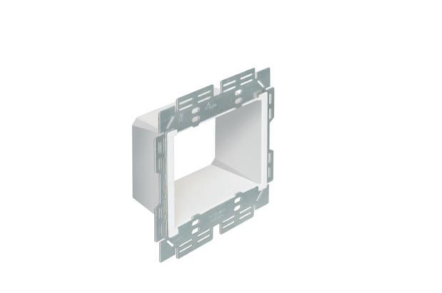
Arlington’s new Furred Wall Box™ kit makes challenging outlet box installations fast and easy!
Versatile mounting options Our high strength FSB series outlet box kits are designed for use with existing 1x2 drywall furring strips – but can also be mounted directly to a concrete block wall between furring strips – so installers can place the box or outlet where it’s needed.
No cable pullout! Accommodates GFCI and USB receptacles. Convenient kits simplify ordering.
Large, pancake-style box with cover
High-strength No breakage in cold weather
Integral Mounting Flanges


FSB2
Current will flow through any path possible to return to the source. Of course, the DMM does not know what path the current flow has taken — only that a certain amount flows back to the meter.
Photo 4 illustrates this error as the worker places fingertips on the test leads while testing a motor starter. Holding onto the tips of both leads will cause the DMM to attempt to measure resistance across the worker’s body, and the actual desired measurement will not be obtained. Always be sure at least one end (if not both ends) of the meter leads is making contact only with the circuit under test; otherwise, a parallel path for meter current flow can be created through the technician’s body.
Disconnect one portion of the circuit (if required).
Another example of parallel resistance is reading through multiple components when troubleshooting. Even the savviest troubleshooter can be caught off guard by this one. This especially applies when reading resistance in control circuits. There will be many parallel paths for current flow in the typical control circuit. Make sure the component under test is isolated from the remainder of the circuit.
Measure resistance only on de-energized circuits.
Do not rely on the DMM for protection. Understanding how the meter works to read resistance is also key to safety. Imagine placing a couple of AA batteries across an energized 120V, 240V, or even a 480V circuit. Not only would the meter most likely be destroyed, but the worker could also receive serious injury. Fortunately, most DMMs will have built-in protective circuitry to protect both the worker and the meter. If set to read resistance and placed on a live circuit, the DMM may emit an audible sound, a flashing LED, or simply fail to read a value depending upon the DMM. This is just another good reason to use quality test equipment and know that DMM before you use it.
SUMMARY
Don’t be fooled by the user-friendliness of the modern DMM. A quality device used correctly can tell the electrical worker the specifics of a circuit that

3. Most clamp DMMs will have some method to indicate where the conductor is to be placed within the clamp for the most accurate reading. Photo 3(a) shows two parallel lines, which is typical, and the conductor must be placed at or below these parallel lines. Photo 3(b) shows an example of placing the conductor near the top of the clamp. This is the circuit from Photo 2 and should read 17A. The reading now is considerably inaccurate.


Photo 4. Testing motor starter contacts is a good example of how an inaccurate resistance reading can be obtained. With the black test lead on L1 and the red test lead on T1, see Photo 4(a), the DMM should indicate “0L” (open circuit) since the starter contacts are open. In Photo 4(b) the technician is using their fingers to hold the test leads in place. The parallel path created as DMM current flows across the worker's body from one hand to the other gives the erroneous reading of 14.16 megohms, indicating faulty contacts.
would be impossible to know otherwise. However, if certain key aspects of measurement techniques are not closely adhered to, inaccurate measurements can result — sometimes grossly inaccurate measurements. Be sure to know your meter and its nuances before you first apply it to a circuit. Understand how your DMM works and its limitations. Follow the manufacturer’s instructions for use,
and apply the DMM tips provided to get the most out of your DMM.
Randy Barnett is an NFPA certified electrical safety professional, a long-time journeyman electrician, instructor and author with expertise in industrial electrical construction and maintenance. He is Electrical Codes & Safety Manager for NTT Training.
Photo
CableStop™ TRANSITION FITTINGS
• TRAY CABLE
• FMC
• MC & PVC MC
• AC90 & ACWU
• TECK Cable


Perfect for data center remote power panel feeds, panels, equipment feeds and EV Chargers in parking garages, Arlington’s Listed CableStop™ Transition Fittings deliver the efficient, cost-effective way to transition feeder cables to 2.5", 3" and 3.5" EMT, IMC and RMC conduit in protective drops, risers and feeds to panels and equipment.
Available with set-screw or compression connections into 2.5", 3" and 3.5" conduit, they ship with multiple end stop bushings that vary the size of the opening – along with a free template select the right bushing for the cable. FROM


Our new CableStop fittings integrate our patented, versatile and SKU-reducing 8412 series cable fittings, with Arlington conduit fittings, allowing for easy transitions to larger knockout sizes.


Ensuring Accuracy in Demand Factors with the NEC
How to dispel common misconceptions when it comes to demand factors and the Code.


By Jennifer Kuether, P.E., Syska Hennessy Group
Engineers often include demand factors in panel schedules and/or load cal culations when preparing an electrical design. It is important to include these as permitted by the Code so that equipment is properly sized and correctly shown on drawings, resulting in an accurate determination of spare capacity. NFPA 70, National Electrical Code (NEC), allows engineers to take into account demand factors for various scenarios in electrical designs. By carefully following the NEC, engineers can avoid several negative scenarios and ensure the success of their projects.

The NEC defines a demand factor as a ratio of the maximum demand to the total connected load; this is in reference to a system or a part of a system that is under consideration.
AREAS OF OVERSIGHT
Two common errors often emerge in electrical designs:
1. Using 125% as a demand factor for continuous loads, and 2. Approaching demand factors as a grey area and therefore devising demand calculations based on the engineer’s generalizations.
17SAVE seconds
Fully assembled, SNAP2IT® fittings handle the widest variety of MC cable AND THE NEW MC-PCS cables.

Compared to fittings with a locknut and screw, you can’t beat these snap in connectors for time-savings!


LISTED SNAP2IT ® CONNECTORS FOR NEW MC-PCS CABLE ...lighting & low voltage circuits in the same cable


• Fits widest range and variety of MC cable 14/2 to 3/3
AC, MC, HCF, MC continuous corrugated aluminum cable and MCI-A cables (steel and aluminum)...including the new MC-PCS cable that combines power and low voltage in the same MC cable
ANY Snap2It Connectors LISTED for MC cable are also LISTED for MC-PCS cable! These products offer the greatest time-savings.
• Fast, secure snap-on installation
• Easy to remove, reusable connector From cable Loosen screw on top. Remove connector from cable. From box Slip screwdriver under notch in Snap-Tite® Remove connector.


Easy to Snap into Box!
Table 1. Correct demand factor applied.
The NEC requires that branchcircuit conductors and overcurrent protection (as well as feeder overcurrent protection) shall be sized at 125% for continuous loads. See related requirements in Secs. 210.19(A)(1), 210.20(A), and 215.3. This requirement is sometimes misinterpreted. Consequently, the engineer applies a 125% demand factor for loads in a panel schedule and/or a load calculation. However, the 125% has already been applied at the branch and feeder level, so applying a second time to determine the load on the distribution equipment is neither necessary nor correct. Demand factors also are never more
than 100%; the demand load should not exceed the connected load.
Refer to NEC Table 220.45 for lighting-load demand factors. This table outlines demand factors that may be used for lighting different occupancy types; demand factors range from 25% to 100% in this table.
CASES IN POINT
Consider the hypothetical panel schedules in Table 1 (incorrect) and Table 2 (correct). These are both representative of the same fictional small commercial office project. The project scope for the examples includes circuiting for a few receptacles and some luminaires. Since
lighting is a continuous load, some engineers mistakenly apply a 125% demand factor for lighting; this is shown in Table 1. One can see that the demand load exceeds the connected load in this panel schedule, which should never be the case. Per NEC Table 220.45, office lighting falls into the “other” category, and the associated demand factor should be 100%. Refer to the panel schedule in Table 2 for the correct version for this project scenario; in this case, all loads are factored at 100% and demand load equals connected load.
NEC AREAS OF EMPHASIS
Aside from the 125% misconception, engineers also sometimes may make
Table 2. Incorrect demand factor applied.
CABLE SUPPORT

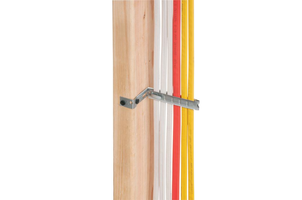
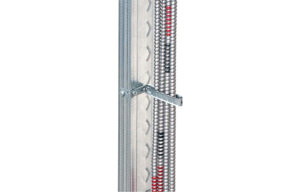
Arlington’s economical CUS6 galvanized steel Cable Support holds cable secure and centered on a metal or wood stud.
It’s perfect for fastening and individual metal clad cables –or six NM cables on a 2x4. to a wood or metal stud, and position the cables. Next bend the strap at the foldline (centerline). Fold the strap over the cables and insert the locking tab in the opening as shown to hold


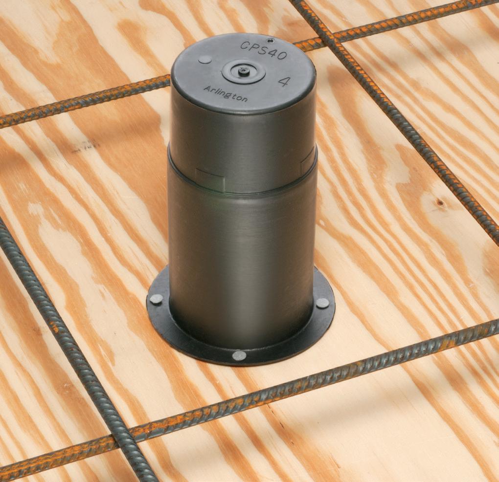
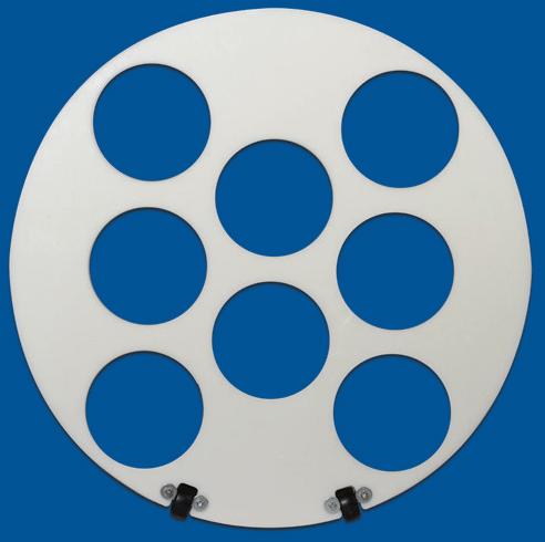
Arlington’s Concrete Pipe Sleeves are the economical way to sleeve through concrete pours in tilt-up construction WALLS – and FLOORS allowing cable and conduit to run easily from one floor to the next.
No costly core drilling – No cutting holes in the form. Plus, you can position the hole prior to pouring the concrete.
• Attaches to form with nails or screws
• Stackable up to 23" h for extra deep pours
• Vents keep wet pipe sleeves from sticking together
• Multiple hole sizes: 1-1/2"


the mistake of assuming that they can determine demand factors on their own. Instead, they should follow the NEC guidelines closely. Below are some especially useful sections to focus on.
Refer to Sec. 220.40 regarding the calculated load of a feeder or service. This Section of the Code indicates that the load for a feeder or service shall not be less than the sum of the associated branch circuits after any applicable permissible demand factors are applied. The NEC does allow demand factors for less than 100% for several scenarios.
It can be reasonably assumed not all occupants in dwelling units will use loads at the same time; therefore, the NEC has several allowances for a reduction of demand load when calculating the service size for a dwelling unit. Per Sec. 220.41, the minimum unit load, which includes most of the receptacles and lights, should not be less than 3VA/SF. This can then be reduced as applicable per Table 220.45.
The demand for motors and fixed heating should be 100% unless there is an exception that satisfies Sec. 220.51 and/or Sec. 430.26, and the AHJ has granted permission for this. An example of a possible application of Sec. 220.51 and/or Sec. 430.26 is electric heaters and/or motors that do not all operate at the same time. In this case, the AHJ may grant permission to use the largest of the non-coincidental loads for consideration.
Another exception cited within Sec. 430.26 is the ability to use historical data from an existing facility when factoring in motor loads for a new facility that is similar to the existing facility. Appliance loads in a dwelling unit may have a 75% demand factor applied for the situation of four or more appliances, per Sec. 220.53.
Table 220.54 shall be used for applying demand factors for electric clothes dryers. This demand factor is more applicable when considering several dwelling units as the demand factor for one to four electric clothes dryers is 100%.
Section IV of Art. 220 also offers an alternative approach for sizing service and feeders for dwelling units; this Section is entitled “The Optional Feeder and Service Load Calculations.” This approach allows for a more bulk-type demand factor, which can be applied for general receptacle/lighting loads,
appliances, and motors; however, there are certain requirements that the engineer should take note of before choosing the optional calculation method. Some examples of these requirements are that multifamily units must have electric cooking and that dwelling units are equipped with electric space heating, air conditioning, or both. Table 220.84(B) can be referenced for the optional load demand factors related to three or more multifamily dwelling units.
For multiple elevators served by the same feeder, there is a demand factor that can be used in Table 620.14. These demand factors are based on a 50% duty cycle — meaning half time on, half time off.
For situations where an engineer is required to determine whether existing distribution equipment has adequate capacity to accommodate new loads resulting from a renovation and/or addition, refer to Sec. 220.87. Actual load usage for the existing equipment should be determined either by reviewing electric utility bills for peak load over the course of a year, or an electrician can perform a 30-day load study — and the peak load from this study can be used. Once the peak load is found, it should be multiplied by 125%; this plus the new load should not exceed the ampacity of the associated feeder or rating of the service.
Receptacles shall be calculated at not less than 180VA for each single or multiple receptacle on a yoke unless it is in a dwelling unit or office. The receptacle load for dwelling units is combined with the general lighting load 3VA/SF and outlined in Sec. 220.41. Note: This does not include receptacles for specific usage such as fixed-in-place appliances. For feeder and service load calculations in office buildings, Sec. 220.43 should be referenced regarding receptacle loads.
For non-dwelling units, Table 220.56 can be used to apply a demand factor to kitchen equipment. This table is especially useful for large commercial kitchens or restaurants because a demand factor of 65% can be applied to six or more units of kitchen equipment.
Section 220.60 describes a situation in which the smaller of two loads may be disregarded in calculating the total load for a feeder or service if it and the other larger load are not likely to run at the same
time. Note: This scenario should be carefully considered — the exception applies to two items that are related to each other through switching and control.
There is an Informational Note below Sec. 430.26 that indicates how demand factors determined for the design of new facilities can be validated against actual historical experience from other similar installations. An example of this would be a new manufacturing facility, which could be based on one in a similar environment with similar equipment usage and operating hours as well as a similar size of facility. Note: AHJ permission would be required to implement this approach for a new facility.
THE BOTTOM LINE
Several ramifications can occur if demand factors are used incorrectly in an electrical design. First, the distribution equipment may be either oversized or undersized. There are negative cost implications for the equipment being oversized as well as an unclear depiction of available spare capacity. For example, if a 125% demand factor is incorrectly applied to each of the loads, it may appear there is no more space to add additional loads in the future. If the equipment is oversized, then the owner may be paying more for the wire and distribution equipment than what is actually needed. Furthermore, there are safety considerations if the equipment is undersized. If an overload occurs, the associated breaker may trip; if it does not, however, then the wire may overheat and cause a fire.

To conclude, it is imperative that engineers avoid adding 125% to the load on panels and/or services and that they take time to carefully decipher the various code sections regarding allowable demand factors. As indicated throughout this article, engineers need to assess demand factors for electrical design as covered in the NEC. It is a comprehensive guide and assists them with providing a minimum standard of care for their projects.
Jennifer Kuether is a licensed professional electrical engineer in 28 states and has nearly 25 years of experience. Jennifer resides in the Chicagoland area and is a supervising engineer and associate partner with Syska Hennessy Group.


(SEE ABOVE)

• Easy snap-in cable installation Save time over 90° 2-screw MC Connectors at same cost per connector
• Handles widest range & variety of cables: 14/2 to 10/2 AC, MC, HCF, MC continuous corrugated aluminum cable, MCI-A cables (steel & aluminum), AC90 and ACG90
• Fast, secure installation...No pullout
• Easy to remove from box...reusable

40900ST

*Some Assembly Required
From homes to prison cells, the modular and panelized construction market is booming. Here’s how it differs in building design, job-site workflow, and codes.
By Tim Kridel, Freelance Writer
This is a story about numbers, starting with 3.7 million, which is the amount of additional homes that the United States needs to meet demand, according to Freddie Mac. Other sources, such as Zillow, estimate the shortage is closer to 4.5 million. Then there’s 76,500, which is the average number of carpenter positions that will go unfilled each year through 2033, according to the U.S. Department of Labor. For comparison, electricians will come up short about 80,200 annually over that period.
Eighty could be the magic number when it comes to tackling the chronic shortages of both housing and skilled trades. That’s the ballpark percentage of work completed on factory-built housing when it arrives at the job site. This catchall
category includes modular and panelized homes and obviously isn’t a new concept. But lately, it’s gained interest and investment, including for multi-dwelling units (MDUs) and commercial buildings such as hospitals and hotels.
“A lot of commercial developers are looking at modular now because of the increased speed, which leads to a faster ROI,” says John McMullen, Modular Building Institute (MBI) marketing director. “Multifamily housing has been a huge sector for commercial modular construction for the past several years. In our 2024 report, multifamily housing was 20% of all commercial modular construction. We don’t see that changing going into next year [because] housing is needed absolutely everywhere.”
Greystar Real Estate Partners is so bullish on the modular business model
that it created a subsidiary devoted to it. In April 2023, the $78-billion rental development and management company opened the Modern Living Solutions factory in Knox, Pa., to design and build apartment modules for MidAtlantic metros, such as Baltimore and Pittsburgh. The plant currently builds a dozen apartment units each week but can ramp up to twice that amount.
“Manufacturing the modules in a factory-controlled environment means that projects can be delivered up to 50% faster than traditional construction with less external risk presented by factors including weather, labor shortages, or on-site safety concerns,” Greystar said in a release. These benefits apply to commercial projects, too.
“It’s cost avoidance because if you can’t find enough labor on site, our team
of Bensonwood
Courtesy

Arlington’s recessed STEEL combination power/low voltage TV BOX™ is the best way to mount an LED or Hi-Def TV flush against a wall.
TV BOX provides power and/or low voltage in one or more of the openings. Plugs and connectors stay inside the box, without extending past the wall.

Designed for use in new or retrofit commercial construction where metal raceway is used, we have a STEEL TV BOX for almost any application!


• Steel box; non-metallic paintable white trim plate
• Easy, secure installation
• Optional covers


The SCOOP™ series of reversible, non-metallic ENTRANCE HOODS, PLATES AND DEVICES protect cable while delivering good looks and installation versatility. They also reduce labor and eliminate extra connections.
Our newest CABLE ENTRY DEVICES come with or without a wall plate for efficient cable management. HOODS for decorator-style wall plates, single and two-gang PLATES install facing in or out...and save time!
• Low voltage cable protection
• Best way


can produce a quality product that’s plug and play on the job site,” says Doug Bruhns, EVP and chief commercial officer of SteelCell, a Baldwin, Ga.-based company that specializes in correctional and medical facilities. “It’s schedule insurance in some ways because if you’re building on site, you don’t really know [what could go wrong].”
Modular also can be a way for developers to meet sustainability goals, including ones that help qualify a project for government incentives.
“With sustainable designs, efficient usage of materials, and speed of construction, Modern Living Solutions units will have a smaller carbon footprint than traditionally built projects,” Greystar said. “Roughly 80% less waste will be produced compared to traditional builds.”
Developers also could build temporary factories near large subdivisions to supply thousands of modules — similar to the concrete batch plants used for major construction projects. A 2022 EC&M article (ecmweb.com/21182394)
explored how this approach could include using robots rather than humans to install the electrical infrastructure in the factory so that even less has to be done on site.
“Some of these national builders have 15 different floor plans,” Chris Haynes, an instructor in the automation and robotics department at State Tech in Linn, Mo., said at the time. “Maybe they mirror [this model]. ‘We can start predrilling holes so we don’t necessarily have to have a guy that knows everything except for getting wire from point A to point B.’ And if they can get this robot to feed wire through, then they don’t even need that. They’ll just need the guy to come in at the end and terminate the connection.”
NO SHORTAGE OF SHORTCUTS
Factories enable the use of automation that’s not possible on job sites. An example is a CNC machine that cuts a floor joist to length and then drills the holes for plumbing and electrical runs — all in one pass rather than the multiple steps
of traditional site building. But that still leaves plenty of site work for electricians.
“Basically 90% of the work is done in the factory for inside the cell,” Bruhns says. “The hookups are 100% on site. They’re hooking into junction boxes that we supply. There is still a ton of work that needs to be done on site for these justice facilities and medical facilities.”
In commercial projects, hookups and other work often are done inside a mechanical-electrical-plumbing (MEP) corridor that runs the length of a series of modules, such as a hallway’s worth of hotel rooms. Once construction is complete, MEP continues to provide maintenance workers with access for the building’s life. In hotels, that reduces the need for them to enter occupied guest rooms. In prisons and jails, it means maintenance doesn’t create opportunities for exchanging contraband or pilfering tools.
“Nowadays, most justice facilities are going with a rear chase concept,” Bruhns says. “Before, there was a lot of front chase work, where you have to bring
FAN FIXTURE BOX


Arlington’s heavy-duty, plated steel fan/ fixture box has an adjustable bracket that mounts securely between joists spaced 16" to 24" o.c.
Flush ceiling installations

FBRS415 is designed for ceilings up to 1-1/4" thick. For 1/2" ceilings, use the pre-bent positioning tab. For other ceiling thicknesses, bend along the appropriate score line.
• 15.6 cu. inch box ships with captive screws, mud cover, installed NM cable connector

In a tight spot? Arlington’s new SNAP-TITE® Transition Fittings offer the time-saving solution for installing additional conduit or cable in an already congested panel. They allow installers to work around tightly spaced, installed fittings in a panel, box or enclosure – where installing and tightening additional locknut fittings would be


Convenient, Time-Saving snaps into a 1/2" knockout and connects 1/2" trade size threaded fittings or pipe.


your tools in through the active facility to perform maintenance. If you’re entering an occupied area, you have to have tool checks to make sure none are taken while you’re doing the maintenance because the inmates will do damage with those.”
Some single-family modular and panelized homes use a similar approach. For example, Bensonwood builds exterior walls with the traditional sandwich of siding, sheathing, framing, and insulation, but it’s followed by a non-structural interior framework of 2×3s that serves as a chase. The drywall, beadboard, or other finish layer is installed on the job site once the MEP work is done.
“All the installation is done on site by local electricians,” says Seth Clarke, director of preconstruction at the Walpole, N.H.-based company.
This “service layer” provides a couple of benefits. First, having a dedicated space for electrical, telecom, IT, and plumbing means that their installation doesn’t require drilling and sawing through insulation and vapor barriers, thus preserving the energyefficient building envelope. It also preserves structural strength because the studs, cripples, plates, and headers are never touched.
“Our CNC equipment notches out the back side, so you have all the raceways already precut into the service layer and then falling into the partitions,” says Hans Porschitz, Bensonwood operations officer. “The machine is also drilling holes at the same height. We’re creating efficiency for electricians on our job sites so they don’t have to drill a bunch of holes. They just pull those runs before the interior finish goes on.”
A second benefit is long term and ties in with the sustainability goal of factory-built housing. Decades from now — when the home is remodeled or when new technologies arrive — those changes can be made entirely in the service layer faster and cheaper.
“In the commercial world, they have bigger buildings, and people don’t want to tear them down,” Porschitz says. “They repurpose them, so they want to be modular in their fit out. We have tried to bring that to residential.”
BUILDING BLOCKS AND STUMBLING BLOCKS
With so many benefits, why isn’t factory construction more common? One reason is that some builders and developers are simply more comfortable with their traditional workflows — drawbacks and all.
“It’s just something different,” says MBI’s McMullen. “Most developers have their ways of doing things. It works for them, and they can turn a profit. Modular construction work is a different mindset. You have to do things in a slightly different order. It takes a lot more capital upfront, especially for big commercial projects.”
The U.S. Department of Housing and Urban Development (HUD) plays a key role because factory-built housing that meets its national code qualifies for special financing options. But some believe HUD could do even more.
“How do we get HUD to issue advance market commitments for largescale factory-built housing, to put tens or hundreds of thousands of units on demand?” U.S. Rep. Jake Auchincloss said in a June 2024 Brookline News interview. “Because that’s how you get the factories to actually get the scale economies they need and go down the production cost curve.”
Stigma is another hurdle. Modular often is lumped in with manufactured — aka “mobile” — homes because they all come out of factories. One fundamental difference is that modular and panelized homes are designed for a one-time installation on a permanent concrete foundation. By comparison, manufactured homes are built on a permanent chassis so they can be trucked to the dealer’s lot and then to the owner’s property. In theory, they can be moved many times after that, although that’s actually uncommon due to the cost, which can easily run $5,000 per move.
“It’s that word — modular versus manufactured — that’s still a stumbling block for a lot of people,” McMullen says. “The end product is no different than traditional construction. You’re getting a permanent building that’s often built better and to higher standards than traditional building. We’re seeing that go away a little bit with more states establishing their modular [code] programs and adopting these standards that we’ve helped create.”
NAVIGATING CODE COMPLIANCE
Codes are one way to distinguish modular and panelized from manufactured.

Courtesy of Bensonwood


Arlington’s Low Voltage Mounting Brackets are mounting of Class 2 communications, computer and cable TV wiring and connections.
Introducing for EXISTING or RETROFIT construction...
Our
• Extra rigidity and stability where performance and visibility are important or critical
• Threaded holes for easy, fast device installation

• Adjustable bracket for 1/4” to 1” wall board thicknesses
The LV1S PLATED STEEL mounting bracket, with its unique X-shaped bracket design, provides excellent stability and secure installation of low voltage devices in 1/4" to 1-1/4" walls - without an electrical box.
Try them all! Metal and Non-metallic for retrofit, nail or screw-on for new work, and others!
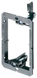
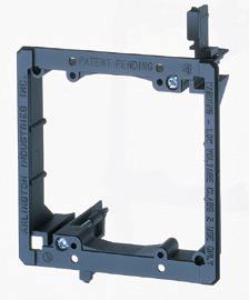


Threaded Holes for easy device installation

“Anything built after 1976 under the HUD Code we consider ‘manufactured housing,’” a HUD spokesperson says. “In most cases, the only distinction between them is that homes sit on this permanent chassis. As far as we’re concerned, no mobile homes are being built anymore. The distinction between a HUD Code manufactured home and a modular home is essentially just that one is built to the HUD Code and one is not.”
The HUD Code is noteworthy for another reason: It has nationwide clout.
“HUD is the only preemptive code that exists,” the spokesperson says. “Local building authorities don’t have independent authority to do their own reinspection.”
Congress is considering changes — such as eliminating the permanent chassis requirement — that could result in the HUD Code expanding to cover a wider range of factory-built housing.
“The real advantage of the HUD Code is that you can build in one state and ship it anywhere in the country,” the HUD spokesperson says. “Many folks who try
to make modular work at scale, folks with a lot of funding, run into the issue of having to build different versions in every jurisdiction where they want to sell it. So a lot of them are excited by the opportunity to be more under the HUD Code.”
Another development is the growing number of statewide building codes, such as Utah’s in 2024.
“Utah was based on the work that we did in Virginia, which was the first state to adopt building standards from the International Code Council and MBI: ICC/MBI 1200 and 1205,” McMullen says.
UL also plays a key role with its Commercial and Industrial Prefabricated Buildings and Units program (QRXA).
“This program is focused on evaluating the electrical systems and components of the building or unit, which are typically in concealed spaces,” says Christopher Jensen, UL Solutions regulatory services manager. “The UL Solutions’ Certificate of Inspection identifies the specific edition of the NEC that was used to inspect the prefabricated
building or unit. At www.UL.com/piq, you can enter ‘QRXA’ into the search field and see that 19 manufacturers have prefabricated buildings inspected under this program.”
QRXA helps avoid delays on the job site — as long as the AHJs know that it exists and that certification means they don’t have to wonder if everything inside the walls meets whatever version of the NEC they use. The good news is that UL is working to build awareness.
“UL Solutions’ Codes and Regulatory Services division has staff that attend many electrical trade shows, conventions, and events, such as the Independent Alliance of the Electrical Industry (IAEI) section meetings, where they provide presentations and information on technical topics of the day, such as modular construction,” Jensen says.
Tim Kridel is an independent analyst and freelance writer with experience in covering technology, telecommunications, and more. He can be reached at tim@timkridel.com.


How to keep renovation and expansion projects on schedule and on budget.
The National Electrical Code (NEC) continues to evolve in response to advances in technology, industry trends, market supply and demand, lessons learned, and public safety. The 2023 Code did not disappoint with new requirements and clarifications. However, clarifications can affect project budget, schedule, and success if they are overlooked.
Selective coordination is one area that can go awry. It was first introduced with the publication of 2005 NEC in Sec. 700.27: “Emergency system(s) overcurrent devices shall be selectively coordinated with all supply side overcurrent protection devices.” Like other new
introductions, the Code-Making Panel clarified the intent of the requirement over multiple Code cycles. The 2023 clarification tries to resolve all doubts.
Selective coordination evaluations involve a detailed study of electrical distribution additions, modifications, and replacements by licensed professional engineers or other qualified people who work in the design, installation, or maintenance of electrical systems.
Electrical distribution changes introduce dynamic system changes with the potential for different results. Re-evaluation is required with every change, including any supply-side or load-side alteration. Both the original coordination effort and future reevaluation efforts
are simplified by keeping no more than four tiers of overcurrent protection devices (OCPDs) from the main service or emergency power supply to the last branch circuit. Having five or six tiers of cascading OCPDs can make selective coordination difficult or impractical.
CHANGES TO THE 2023 NEC
Selective coordination (Sec. 700.32) impacts both non-health care emergency power systems and health care facility life safety electrical distribution systems. New and existing systems are commonly served by an on-site power supply system, including generators, inverters, and other listed/approved alternative stored energy systems.

Section 700.32 was reorganized into three parts, including general, replacements, and modifications. All three parts identify a requirement for OCPDs to be selectively coordinated with all supply-side and load-side OCPDs. The replacement or modification of any OCPD requires a reevaluation of the system for selective coordination. Likewise, additions, replacements, and modifications of the emergency or life safety system require reevaluation to ensure selective coordination.
What types of equipment constitute a change?
• Transformers, load-side or line-side.
• OCPDs, including additions, replacements, and modifications of fuses or circuit breakers.
• New distribution equipment, including branch panel boards, distribution panels, switchboards, switchgear, and motor control centers.
• New power sources, including generators, solar arrays, fuel cells, or microgrids.
What is the impact on the owner or owner’s representative?
If the facility is less than six years old, they’re likely in a good position. The
following is recommended for master planning and the life cycle of a facility:
• Maintain. Maintain the professional engineer’s electronic models of the electrical distribution system evaluations for selective coordination, available fault current, and arc flash. It is easier and more cost effective for the design professional to update the model with small changes as they occur rather than performing a full facility evaluation with every project.
• Partnership. Develop a stewardship partnership with one engineering professional to maintain a backup copy of your electronic models and update them with every addition, modification, or replacement. The design professional will act as a librarian for your electronic model, maintain it, and share it with you and other design professionals who provide you with service as appropriate.
• Budget. Include a project budget line item for the librarian to update the model when you are working with design professionals other than your librarian partner.
If the facility is more than six years old, the owner might have thought these requirements only applied to new construction or additions — but that’s incorrect. The legacy portions of the building’s electrical distribution system
are not exempt. An addition, replacement, or modification could arguably result in a range of unforeseen conditions between a few small changes and a complete modification of the building’s emergency or life safety electrical distribution branch circuits.
What can you do to prevent selective coordination conflicts from crippling the budget or schedule of a future facility addition or renovation project? Follow these proactive planning tips.
• Model. Develop an electronic model of the existing electrical distribution system with the help of a licensed design professional. The design professional will provide an initial evaluation to identify any existing concerns.
• Address. Communicate existing selective coordination concerns with a planned approach.
• Maintain and partner. Keep the electronic models in partnership with a trusted license design professional.
Proactive planning will reduce unknowns, supply preliminary insight, and protect renovations/additions so they stay on budget and schedule.
Brian Leavitt, P.E. is a senior principal and director of electrical engineering for IMEG’s Technical Operations Team.
The Basics of Data Loggers
How to master AC and DC current and voltage measurements using a data logger.

By Terry Nagy, CAS Data Loggers
Acommon data logging application is measuring voltage or current flowing into or out of a piece of equipment, such as a user monitoring current in solar cells, inverters, or storage batteries. These measurements can be broadly classified into two groups: AC and DC. Depending on the levels involved, some data loggers can directly measure DC voltage and current. Except for power/energy application-specific models, most data loggers cannot measure AC voltage or current directly and require external transducers to convert the parameter of interest into a signal that the data logger can measure and record.
AC VOLTAGE AND CURRENT DATA LOGGERS
For AC applications, there are several types of data loggers specifically designed to measure voltage and current. These include units supplied with current transformers or Rogowski coils supporting a specific current range. If you need to monitor AC signals that don’t match up to the range of these recorders or need to monitor a mix of AC and DC voltage and/or current inputs, you can use a universal input data logger. These can be outfitted with transducers to measure almost any type of input — from millivolts to microamps to thousands of volts or amps.
AC VOLTAGE MEASUREMENTS
• AC voltage transducers — If your application involves tracking incoming line voltage, several vendors provide standard AC voltage transducers for
measuring typical AC line voltages from 110VAC to 480VAC. There are also specialized models available for either low voltages, such as 12VAC found in some control circuits, or potential transformers that can step down very high voltages (5,000VAC to 14,440VAC) to 120VAC, which can be measured using a standard transducer. These are available in both single- and multi-phase versions and with either DC voltage or 4-20mA current outputs scaled to output average or true rms values.
• AC voltage signal conditioner modules — If your application requires the measurement of small AC voltages or a large number of channels, 5B series signal conditioner modules are available with 100mVAC to 700VAC inputs.
• AC voltage isolators — Some applications require recording the actual AC voltage waveform to look for anomalies that last less than one line cycle. Voltage isolators provide a scaled output voltage that is directly proportional to the input voltage (e.g., 150VAC in to ± 5VDC out).
AC CURRENT MEASUREMENTS
• AC transducers — A standard method of measuring AC on a power line-connected device is to use an AC transducer, which converts an alternating current to a DC voltage or 4-20 mA signal that can be measured with the data logger. As is the case with AC voltage sensors, current transducers are available in both single- and multiphase models. The current transducers can utilize either an internal currentsensing element for small currents (up to about 20A AC) or an external current transformer or sensor (for currents up to thousands of amps).
• Clamp-on current sensors — Clamp-on current sensors are available in a variety of models and current ranges with either DC or AC voltage outputs. Clamp-on sensors are easy to use: Simply open the clamp, and place it around one of the current-carrying conductors. They are ideal for temporary installations and can easily be moved from site to site, although they are somewhat more expensive than fixed current transducers.
• Split-core transformers — Splitcore transformers are very similar to clamp-on current sensors but are intended for semi-permanent instal lations. They consist of a transformer where one of the legs can be opened or removed to place around the conductor and then be secured with a latch or some other type of fastener. Some models pro vide an AC output that must be used with a current transducer to provide a signal for the data logger, while others have built-in signal conditioning to provide a DC voltage or current that can be mea sured with the data logger.
• Rogowski coils — A Rogowski coil is a specially wound toroidal coil that can be opened up and placed around a conductor carrying an alternating cur rent. The magnetic field generated by the alternating current induces a voltage in the coil. This voltage is proportional to the rate of change of current in the conductor. This voltage is then electronically integrated to provide an output voltage that mimics the current waveform in the conductor. Rogowski coils are suitable for the measurement of currents up to thousands of amps.
DC VOLTAGE AND CURRENT DATA LOGGERS

For DC applications, there are data loggers specifically designed to measure voltage and current using probes that can be directly connected to the signal source. These models typically cost less and are easier to set up, but, in turn, they offer less flexibility. If you think that your range of measurements may change in the future, use a data logger with an external transducer, which will allow you to change the input range by connecting a different transducer. Again, if you need to log other signals in addition to voltage/current — or if you need to monitor a mix of DC and AC voltage/ current — you can configure a generalpurpose universal input data logger with appropriate transducers to enable the simultaneous measurement of multiple input signal types.
DC VOLTAGE MEASUREMENTS
• Attenuators — The simplest method of measuring a DC voltage that is outside the measurement range of the
This twice-a-month e-newsletter delivers the latest trends and information on electrical safety, reports on specific accidents in the field, and provides tutorials and evergreen safety content that can be used for reference and training.
Topics covered include:
• Best practices for safely working on electrical equipment
• Accidents and investigations
• Arc flash
• PPE
• Shock and electrocution
• Fire and security
• Safety audits
Safety Matters Subscribe Today
See all of our EC&M e-newsletters at www.ecmweb.com

EV Infrastructure
This twice-a-month e-newsletter tracks the development, design, installation, and safe operation of electric vehicle supply equipment and systems.
Topics covered include:
• Applying NEC requirements
• Industry news and trends
• New products
• Federal investment allocation
• National EV charging infrastructure buildout development
Subscribe Today
See all of our EC&M e-newsletters at www.ecmweb.com
data logger is to use an attenuator. This is just a fancy name for a few resistors wired together to divide the incoming voltage to a range compatible with the data logger. If the voltage you need to measure is less than about 50VDC, you can find a lowcost solution. However, OSHA considers anything above this level as hazardous, and we don’t recommend them for these applications. In addition, there are three issues to note when using attenuators: There is no isolation, which can lead to cross-talk and measurement errors when using more than one attenuator.
If the low side of the DC voltage is not at earth potential, the common mode voltage can cause errors and — in the worst case — damage to the data logger. The divider imposes some resistive loading that can affect the measurement accuracy, particularly in sensors with a high output impedance.
• DC voltage transducers — Several companies offer packaged DC voltage transducers that convert the incoming voltage to a range that is compatible with the data logger. These units offer the advantages of being able to measure very small (<0.1V) and very high (>1,000V) inputs. These units feature input-to-output isolation and only cause minimal loading effects. DC voltage transducers can also provide an output either as a voltage or as a 4-20 mA signal, which is beneficial if there is a long distance between your measurement point and the data logger.
• Signal conditioner modules — Standard signal conditioner modules provide up to 1,500V of isolation and amplification or attenuation in compact packages that are suitable for multichannel systems. They are available in a wide range of input voltages and provide a DC voltage output. Because of their small size and their ability to mix and match input types and ranges, signal conditioner modules are very useful in systems with a high channel count.
DC CURRENT MEASUREMENTS
• Current shunts — A current shunt consists of a conductor with a
very small (but known) resistance. The current flowing through the shunt creates a voltage drop that can be measured with the data logger. These are available in ranges to handle 5A to 1,000A and provide an output from 0V to 0.1V. Like the attenuators for DC voltage measurements, you must pay attention to common mode voltage when using current shunts; we always recommend that they be used on the low side of the current path. The advantage of current shunts is their simplicity and low cost, but they should not be used for an extended period at more than two-thirds of their rated current, or the accuracy may be affected.
• DC current transducers — DC current transducers often use a Hall Effect sensor to allow current measurement without direct contact with the conductor. The disadvantage of these sensors is that they typically have limited resolution for lower currents; however, they work very well for higher currents.
This article serves as a guide for educating electrical professionals on the basics of voltage and current measurement. Providing precise, real-time monitoring of electrical systems, these devices are a critical diagnostic tool, allowing technicians to track fluctuations, detect irregularities, and analyze trends in both AC and DC circuits over time. By capturing voltage drops, current spikes, and power factor variations, data loggers enable accurate troubleshooting of electrical loads, battery systems, solar panels, and industrial equipment. Used in residential, commercial, and industrial settings, their ability to record data in real-world conditions ensures electricians can diagnose issues, optimize performance, and improve safety in various applications and market settings.
Terry Nagy is Engineering Manager at CAS Data Loggers in Chesterland, Ohio. He is an electrical engineer with more that 20 years experience in measurement and instrumentation systems, including PC and standalone data acquisition systems, data loggers, and real-time systems.
PRODUCT NEWS/AD INDEX

Standby Generators
The company announced its latest home standby generator design, including the new 28kW model. The new generator design includes built-in cellular connectivity as a standard feature, an advanced controller delivering important new capabilities (such as electronic oil level sensing and gas pressure monitoring), and an electronic fuel and ignition control (EFIC) system, providing improved motor starting capability and lower fuel consumption. In addition, the new design allows the ability to fully integrate with ecobee smart thermostats, enabling customers to display vital information about their generator directly on their wall, and giving them greater control over their home energy management.
Generac
Facilities
Magnalux

Enclosure
The company has introduced IP68 1550ZF, flanged versions of all 18 sizes in the 1550Z rugged thick wall heavy-duty die-cast enclosure family. The full-size flange is spotwelded to the base to give a very strong and smooth mounting plate for use when the units are secured to a surface. The 18 sizes range from 50 mm × 45 mm × 30 mm to 223 mm × 147 mm × 83 mm, with the lid’s thickness ranging from 5 mm to 33 mm in depth depending on the size. The tongue and groove design and a pre-formed onepiece silicone rubber gasket gives the IP68 environmental protection so the enclosures are ideal for installation in environments where dust and water will be present.
Hammond

Battery Energy Storage System
The xStorage battery energy storage system (BESS) optimizes energy usage and supports electric vehicle integration, and grid modernization. In the event of a utility power interruption, the battery provides an environmentally friendly backup, reducing reliance on traditional generators with its 250kWh to 1,000kWh of usable stored energy. Additionally, it enables efficient solar self-consumption by storing excess energy from on-site sources like solar panels and supports demand response by using stored energy to manage peak demands and avoid utility fees. The xStorage system includes a control cabinet with auxiliary transformer, power conversion system (PCS)/inverter, and up to three battery cabinets — each housing six or eight battery modules.
Eaton
(Every effort is made to ensure the accuracy of this index. However, the publisher cannot be held responsible for errors or omissions.)
CODE BASICS
NEC Requirements for Cables
A cable type is one of 11 specific Chapter 3 wiring methods, each of which has specific requirements.
By Mike Holt, NEC Consultant
The NEC contains 12 articles (320 through 340) covering types of cables. The cable types covered include: armored cable (Type AC); flat cable assemblies (Type FC); Flat conductor cable (Type FCC); integrated gas spacer cable (Type IGS); metal-clad cable (Type MC); mineral-insulated, metal-sheathed cable (Types NM and NMC); instrumentation tray cable (Type ITC); power and control tray cable (Type TC); Type P cable; service-entrance cable (Types SE and USE); and underground feeder and branch-circuit cable (Type UF).Any cable must be listed and any fittings used with it must be listed for use with that type of cable.
Let’s compare two commonly used cable types: armored cable and metal clad cable.
A TALE OF TWO CABLES
Article 320 covers the use, installation, and construction specifications of armored cable (Type AC), as shown in Fig. 1
Type AC cable is a fabricated assembly of conductors in a flexible interlocked metallic armor with an internal bonding strip in intimate contact with the armor for its entire length [Art. 100]. It contains up to four phase conductors and one neutral insulated conductor, sizes 14 AWG through 1 AWG, individually wrapped in a moisture-resistant, fire-retardant paper contained within a flexible spiral metal sheath.
Article 330 covers the use, installation, and construction specifications of metal-clad cable, Type MC, as shown in Fig. 2 on page 61.
Type MC cable is a factory assembly of one or more insulated circuit conductors (maybe with optical fiber members), enclosed in an armor of interlocking metal tape, or a smooth

Fig. 1. Armored cable is a fabricated assembly of conductors in a flexible interlocked metallic armor with an internal bonding strip in intimate contact with the armor for its entire length.
or corrugated metallic sheath [Art. 100]. It contains any number of insulated conductors, 18 AWG through 2,000kcmil, with an overall polypropylene wrap enclosed in a metal sheath of either corrugated or smooth copper or aluminum tubing, or in spiral interlocked steel or aluminum.
PERMITTED USES
You can use Type AC cable [Sec. 320.10] in:
1. Feeders and branch circuits (exposed or concealed).
2. Cable trays.
3. Dry locations.
4. Plaster (dry locations).
5. Voids in block walls where not exposed to excessive moisture or dampness.
And in plenum spaces per Sec. 300.22(C)(1). The “Uses Permitted”
is not an exhaustive list; other suitable uses are permitted if approved by the authority having jurisdiction.
Where can you use Type MC cable?
A) General Uses.
1. Branch circuits, feeders, and services.
2. Power, lighting, and powerlimited circuits.
3. Indoor or outdoor locations.
4. Exposed or concealed.
5. Directly buried (if identified for the purpose).
6. In cable tray (if identified for the purpose).
7. In raceway.
8. As aerial cable on a messenger.
9. In hazardous (classified) locations as permitted in Sec. 501.10(B)(5),
Sec. 502.10(B)(4), and Sec. 503.10(A)(1).
10. In plaster in dry locations.
11. In damp or wet locations, where a corrosion-resistant jacket is over the metallic sheath.
(B) Specific Uses.
1. In a cable tray per Art. 392.
2. Direct-buried, if protected per Sec. 300.5.
3. As service-entrance cable, if installed per Sec. 230.43.
4. Outside buildings, if complying with Sec. 225.10, Sec. 396.10, and Sec. 396.12.
BARRED USES
You can’t use Type AC cable [Sec. 320.12]:
1. Where subject to physical damage.
2. In damp or wet locations.
3. In voids of block or tile walls that are exposed to excessive moisture.
4. Where exposed to corrosive conditions.
5. In plaster finish or concrete in wet or damp locations.
You can’t use Type MC cable where [Sec. 330.12]:
1) Subject to physical damage.
2) Exposed to the destructive corrosive conditions in a or b (below), unless the metallic sheath or armor is resistant to the conditions or is protected by material resistant to the conditions:
a) Direct burial in the earth or embedded in concrete unless identified for the application.
b) Exposed to cinder fills, strong chlorides, caustic alkalis, or vapors of chlorine or hydrochloric acids.
3) Exposed work, framing members, and roof spaces.
Exposed Type AC cable, except as provided in Sec. 300.11(B), must closely follow the surface of the building finish or running boards. If installed on the bottom of floor or ceiling joists, it must be secured at every joist and not subject to physical
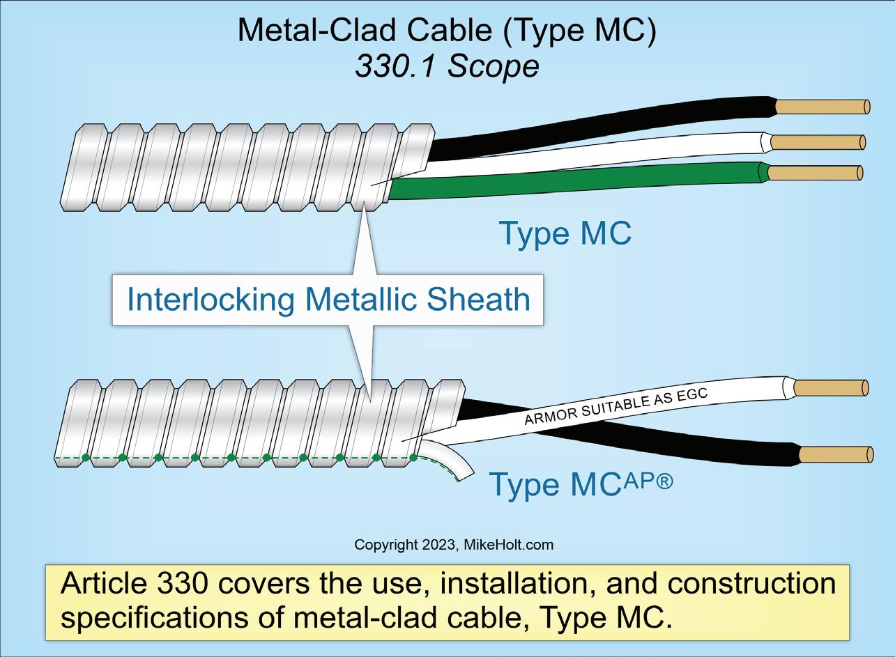
Fig. 2. Metal clad cable is a factory assembly of one or more insulated circuit conductors (maybe with optical fiber members), enclosed in an armor of interlocking metal tape, or a smooth or corrugated metallic sheath.
damage [Sec. 320.15]. For Type MC, the requirements [Sec. 330.15] are the same. Type AC cable installed through or parallel to framing members or furring strips must be protected against penetration by screws or nails by maintaining 11/4 in. of separation between the cable and the nearest edge of a wood framing
Never bend any cable in a manner that may damage it.
member or furring strip or by a suitable metal plate per Sec. 300.4(A), (C), and (D) [Sec. 320.17]. For Type MC, the requirements [Sec. 330.17] are the same.
Type AC cable in roof spaces within 6 ft of the nearest edge of the scuttle hole entrance run across the top of framing members must be protected by guard strips that are at least as high as the cable [Sec. 320.23(A)]. For Type MC, the requirements [Sec. 330.23] are the same.
BENDING, SECURING, SUPPORTING
Never bend any cable in a manner that may damage it. For Type AC, limit
bending of the inner edge of the cable to a radius of at least five times the cable diameter [Sec. 320.24]. For Type MC, what you do depends upon whether the cable is smooth sheathed or interlocked, and what its size is [Sec. 320.24(A)(1)-(3) and (B)]. For example, for smooth sheathed cable (up to 3/4 in. in external diameter), limit the bending radius of the inner edge of the cable to 10 times the external diameter of the metallic sheath.
You can support and secure either type of cable with staples, cable ties listed and identified for securing and supporting, straps, hangers, similar fittings, or other approved means designed and installed so the cable is undamaged. You can use their respective cable fittings as a means of cable support
Type AC cable must be secured within 12 in. of every outlet box, junction box, cabinet, or fitting and at intervals not exceeding 41/2 ft [Sec. 320.30(B)]. For Type MC cable with four or fewer conductors sized no larger than 10 AWG, the interval is 6 ft [Sec. 330.30(B)].
Type AC cable must be supported at intervals not exceeding 41/2 ft (6 ft for Type MC). Cables installed horizontally through framing members are considered supported and secured if such support does not exceed 41/2-ft intervals
CODE BASICS
(6 ft for Type MC) [Sec. 320.30(C), Sec. 330.30(C)]].
Either type of cable can be unsupported and unsecured:
• Where fished through concealed spaces [Sec. 320.30(D), Sec. 330.30(D)].
• Not more than 6 ft long from the last point of cable support or Type AC cable fitting to the point of connection to a luminaire within an accessible ceiling. Type AC cable can be unsupported and unsecured where not more than 2 ft long at terminals and where flexibility is necessary [3 ft for Type MC].
BOXES AND FITTINGS
Unless the termination fitting provides protection, you must install an insulating anti-short bushing at each Type AC cable termination. The termination fitting must permit the visual inspection of the anti-short bushing once the cable has been installed [Sec. 320.40]. There’s no corresponding requirement for Type MC.
Use Table 310.14 to determine ampacity for either cable type. Where more than two Type AC (or Type MC) cables touch thermal insulation, caulking, or sealing foam, adjust the ampacity of the conductors per Table 310.15(C)(1) [Sec. 320.80(A), Sec. 330.80(B)].
EQUIPMENT GROUNDING CONDUCTOR
Type AC cable can serve as an equipment grounding conductor (EGC) [Sec. 250.118(A)(8)], as shown in Fig. 3.
The internal aluminum bonding strip is not an EGC, but it allows the interlocked armor to serve as one because it reduces the impedance of the armored spirals to ensure a ground fault will be cleared. The combination of the aluminum bonding strip and the cable armor is what creates the EGC. The effective ground-fault current path must be maintained by using fittings specifically listed for Type AC cable [Sec. 320.40]. See Sec. 300.12, Sec. 300.15, and Sec. 300.10.
The outer metal sheath of traditional interlocked Type MC cable cannot serve as an EGC, so this cable must contain an EGC of the wire type per Sec. 250.118(A)(10)a, as shown in Fig. 4.
The outer metal sheath of all-purpose Type MC cable with an uninsulated

3. Type AC cable can serve as an equipment grounding conductor.

4. The outer metal sheath of traditional interlocked Type MC cable cannot serve as an EGC.
aluminum grounding/bonding conductor can serve as an EGC per Sec. 250.118(A)(10)b.
KNOW THE REQUIREMENTS
Because a cable is essentially a self-contained wiring system, it could seem cables all have pretty much the same requirements. The reality is those requirements may have big “redo the work” differences,
even between two similar types such as Type AC and Type MC. Know and implement the requirements for each specific cable type.
These materials are provided by Mike Holt Enterprises in Leesburg, Fla. To view Code training materials offered by this company, visit www.mikeholt. com/code.
Fig.
Fig.
CODE QUIZ OF THE MONTH
Test Your Code IQ
How much do you know about the National Electrical Code?
By Mike Holt, NEC Consultant
All questions and answers are based on the 2023 NEC.

Q1: In a dwelling unit, any wall space, including space measured around corners and unbroken along the floor line by doorways, fireplaces, fixed cabinets, and similar openings, shall be considered wall space when the wall space is at least wide.
a) 2 ft c) 4 ft
b) 3 ft d) 5 ft
Q2: A means external to enclosures for connecting intersystem conductors shall be provided at the service equipment or metering equipment enclosure and disconnecting means of buildings or structures supplied by a feeder or branch circuit.
a) bonding
b) ungrounded
c) secondary
d) bonding and ungrounded
Q3: Stainless steel and aluminum fittings and enclosures shall be permitted to be used with galvanized steel RMC, and galvanized steel fittings and enclosures shall be permitted to be used with aluminum RMC where not subject to
a) physical damage
b) severe corrosive influences
c) excessive moisture
d) all of these
Q4: Metallic structures for battery support systems shall be provided with nonconducting support members for the cells or shall be constructed with a continuous material, and paint alone shall not be considered as an insulating material.
a) insulating c) semiconductive
b) conductive d) none of these
Q5: The connection of the system bonding jumper for a separately derived system shall be made on the separately derived system from the source to the first system disconnecting means or overcurrent device.
a) in at least two locations
b) in every location that the grounded conductor is present
c) at any single point
d) effectively
Q6: For installations consisting of not more than two 2-wire branch circuits, the service disconnecting means shall have a rating of not less than
a) 15A c) 25A
b) 20A d) 30A
See the answers to these Code questions online at ecmweb.com/55270870.
CODE VIOLATIONS
Illustrated Catastrophes
By Russ LeBlanc, NEC Consultant
All references are based on the 2023 edition of the NEC.
WRONG PIZZA TOPPING
When Sec. 230.29 states “Service conductors passing over a roof shall be securely supported by substantial structures,” I don’t think that means using a sign as the means of support. These overhead service conductors are resting on top of the “Z” in the “PIZZA” sign. If wind and rain cause those conductors to swing and sway in the breeze, they could get damaged from rubbing against the edge of the sign and cause one heck of an arc flash if they short out. A separate mast or other substantial structure should be used to support service conductors passing over a roof. These wires are attached to a mast on the back side of the building, but either the mast needs to be higher or the point of attachment on the utility pole where they originate needs to be higher to provide clearance above the sign.
Section 230.24(A) requires overhead service conductors to have a clearance of at least 8 ft above the roof. For systems not exceeding 300V between conductors, Exceptions No. 2 and No. 5 allow a
LOUSY LAMPHOLDER LAYOUT

reduced clearance of 3 ft. I’m not so sure there is at least a 3-ft clearance for this entire span, but, in any case, the wires should certainly not be in contact with the sign.
Rust and corrosion are certainly taking their toll on the metal raceway installed here. It may be hard to see in this photo, but the rust is so bad that the wires in the raceway are exposed near the short 90° elbow near the box. Section 300.6 requires equipment to be suitable for the environment where they are installed. Perhaps nonmetallic wiring methods and boxes may have been a better choice for this seaside location. The other thing I’m wondering here is whether the installer spliced the branch-circuit wiring to the leads on the weatherproof lampholder inside the raceway. Were the lampholder leads long enough to make it to the box without splicing inside the raceway? Generally speaking, Sec. 300.13(A) prohibits splices or taps inside of raceways like this. Most weatherproof lampholders that I have installed were marked to indicate they must be aimed horizontally or below. Facing the lampholder up to the sky like this one allows rainwater to enter right into the lampholder and will most likely cause rapid deterioration of the socket — and could even be dangerous by increasing the shock and fire hazard. Section 110.3(B) requires equipment to be used and installed “in accordance with any instructions included in the listing, labeling, or identification.”
To place a display ad (1/6 page or larger), call the Advertising Sales Representative for your area.
Vice President
Mike Hellmann
Andover, MA • (978) 289-0098
E-mail: mhellmann@endeavorb2b.com
Western U.S. & Western Canada
Ellyn Fishman | Key Account Manager (949) 239-6030
Email: efishman@endeavorb2b.com
Northeast U.S. & Eastern Canada
David Sevin | Account Manager 24 Houghton Street • Barrington, RI 02806 (401) 246-1903
E-mail: dsevin@endeavorb2b.com
Midwest, Southeast,and Southwest
Jay Thompson | Account Manager
7450 W. 130th Street, Suite #210 Overland Park, KS 66213 • (913) 967-7543
E-mail: jthompson@endeavorb2b.com
Marketplace/Inside Sales
Steve Suarez | Media Account Exec 7450 W. 130th Street, Suite #210 Overland Park, KS 66213 • (816) 588-7372
E-mail: ssuarez@endeavorb2b.com


CODE VIOLATIONS
By Russ LeBlanc, NEC Consultant

How well do you know the Code? Think you can spot violations the original installer either ignored or couldn’t identify? Here’s your chance to moonlight as an electrical inspector and second-guess someone else’s work from the safety of your
living room or office. Can you identify the specific Code violation(s) in this photo? Note: Submitted comments must include specific references from the 2023 NEC.
Hint: This bursts my “bubble.”
‘TELL THEM WHAT THEY’VE WON...’
Using the 2023 NEC, correctly identify the Code violation(s) in this month’s photo — in 200 words or less — and you could win a $25 Amazon gift card. E-mail your response, including your name and mailing address, to russ@russleblanc.net, and Russ will select one winner (excluding manufacturers and prior winners) at random from the correct submissions. Note that submissions without an address will not be eligible to win.
JANUARY WINNER

This month’s winner is Robert Mutton with The Inspector, LLC in Burke, N.Y. He knew that the wiring inside this red “T” conduit body is not accessible as required by Sec. 314.29(A). The electrical metallic tubing (EMT) raceway installed tight against the cover of the conduit body is blocking access to the wiring inside the conduit body. The Art. 100 definition of “accessible” (as applied to wiring methods) is “capable of being removed or exposed without damaging the building structure or finish or not permanently closed in or blocked by the structure, other electrical equipment, other building systems, or finish of the building.” This definition was revised for 2023 to address this scenario, which was not previously included in that definition or the requirements in Sec. 314.29(A). Now, it is unquestionably a violation to have an installation like this.


Your business is building for tomorrow. Our business is providing the sustainable solutions to get you there.
Whether wiring new builds or retrofitting existing spaces, our consultative solutions streamline your workflow, boost efficiency, and deliver the performance your projects demand.
From planning to installation, Southwire’s engineering team helps you make sustainable choices, reduce embodied carbon, and future-proof your projects—without compromising on quality or profitability.
From smart homes to commercial spaces, build greener, safer, and more efficient structures— one wire pull at a time.
Are your materials making the grade? Scan here to check now.


NO BURN-THROUGH CHAMPION DUCT® ELBOWS SOLVE UTILITIES CHALLENGES
No burn-through eliminates elbow repairs
Light weight facilitates a smooth, safe installation
Fault resistance makes repairing cables easy
Durable and corrosion-resistant for lower total cost of ownership


