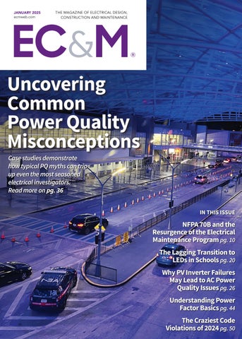
Case studies demonstrate how typical PQ myths can trip up even the most seasoned electrical investigators. Read more on pg. 36
IN THIS ISSUE
NFPA 70B and the Resurgence of the Electrical Maintenance Program pg. 10
The Lagging Transition to LEDs in Schools pg. 20 Why PV Inverter Failures May Lead to AC Power Quality Issues pg. 26 Understanding Power Factor Basics pg. 44
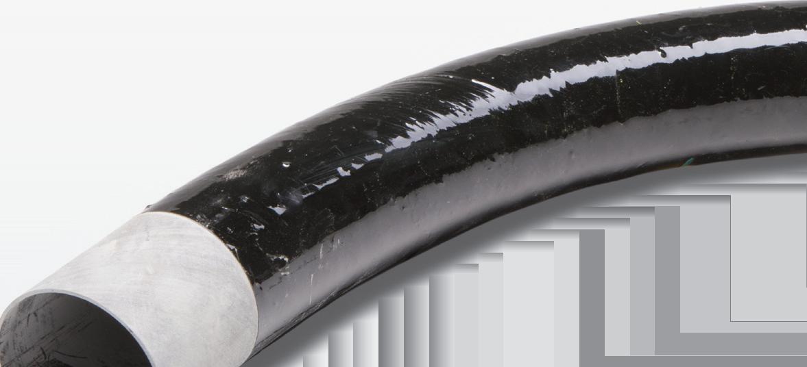
Weighs considerably less than other commonly used conduit and allows for more efficient install times
CORROSION RESISTANT
Withstands harsh environments without degrading
LOW COEFFICIENT OF FRICTION
Allows easier pull through of cables
COST EFFECTIVE
Lower cost of shipping and installation compared to other commonly used conduit
ROBUST THERMAL PERFORMANCE
Epoxy thermoset resin delivers an operating temperature of -40°F to 230°F
ECMWEB.COM
With its exclusive online content, ecmweb.com is a valuable source of industry insight for electrical professionals. Here’s a sample of what you can find on our site right now:
THE 15 MOST UNUSUAL WORLDWIDE POWER OUTAGES OF 2024
Gallery A look at the most unusual worldwide power outages of 2024. ecmweb.com/55252439
EC&M TECH TALK — AN ELECTRICAL SAFETY REFRESHER
Video In this EC&M Tech Talk, Randy Barnett covers important electrical safety requirements addressed by the NFPA 70E standard. ecmweb.com/55252401
8025787
PREVENTING OTHERS FROM CREATING UNSAFE ELECTRICAL CONDITIONS
Safety Electrical Safety Expert
Mark Lamendola discusses how to maintain control when it comes to creating a safe work environment for yourself and others. ecmweb.com/55252548
Editorial
Group Editorial Director - Buildings & Construction: Michael Eby, meby@endeavorb2b.com
Editor-in-Chief: Ellen Parson, eparson@endeavorb2b.com
Media Account Executive – Classifieds/Inside Sales: Steve Suarez, ssuarez@endeavorb2b.com
Production and Circulation
Production Manager: Josh Troutman, jtroutman@endeavorb2b.com
Ad Services Manager: Deanna O’Byrne, dobyrne@endeavorb2b.com
User Marketing Manager: James Marinaccio, jmarinaccio@endeavorb2b.com
Endeavor Business Media, LLC
CEO: Chris Ferrell
CDO: Jacquie Niemiec
COO: Patrick Rains CRO: Paul Andrews
CMO: Amanda Landsaw CALO: Tracy Kane
EVP, Group Publisher – Buildings, Energy & Water: Mike Christian
Electrical Construction & Maintenance (USPS Permit 499-790 , ISSN 1082-295X print, ISSN 2771-6384 online) is published monthly by Endeavor Business Media, LLC. 201 N. Main St 5th Floor, Fort Atkinson, WI 53538. Periodicals postage paid at Fort Atkinson, WI, and additional mailing offices. POSTMASTER: Send address changes to Electrical Construction & Maintenance, PO Box 3257, Northbrook, IL 60065-3257. SUBSCRIPTIONS: Publisher reserves the right to reject non-qualified subscriptions. Subscription prices: U.S. ($68.75 year); Canada/Mexico ($ 112.50); All other countries ($162.50). All subscriptions are payable in U.S. funds. Send subscription inquiries to Electrical Construction & Maintenance, PO Box 3257, Northbrook, IL 60065-3257. Customer service can be reached toll-free at 877-382-9187 or at electricalconstmaint@omeda.com for magazine subscription assistance or questions.
Printed in the USA. Copyright 2025 Endeavor Business Media, LLC. All rights reserved. No part of this publication may be reproduced or transmitted in any form or by any means, electronic or mechanical, including photocopies, recordings, or any information storage or retrieval system without permission from the publisher. Endeavor Business Media, LLC does not assume and hereby disclaims any liability to any person or company for any loss or damage caused by errors or omissions in the material herein, regardless of whether such errors result from negligence, accident, or any other cause whatsoever. The views and opinions in the articles herein are not to be taken as official expressions of the publishers, unless so stated. The publishers do not warrant either expressly or by implication, the factual accuracy of the articles herein, nor do they so warrant any views or opinions by the authors of said articles.
Reprints: Contact reprints@endeavorb2b.com to purchase custom reprints or e-prints of articles appearing in this publication.
Photocopies: Authorization to photocopy articles for internal corporate, personal, or instructional use may be obtained from the Copyright Clearance Center (CCC) at (978) 750-8400. Obtain further information at www.copyright.com.
Archives and Microform: This magazine is available for research and retrieval of selected archived articles from leading electronic databases and online search services, including Factiva, LexisNexis, and ProQuest.
Privacy Policy: Your privacy is a priority to us. For a detailed policy statement about privacy and information dissemination practices related to Endeavor Business Media products, please visit our website at www.endeavorbusinessmedia.com.
Please Note: The designations “National Electrical Code,” “NE Code,” and “NEC” refer to the National Electrical Code®, which is a registered trademark of the National Fire Protection Association.
Corporate Office: Endeavor
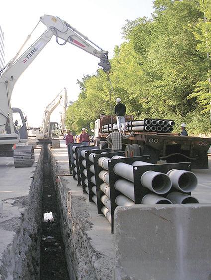
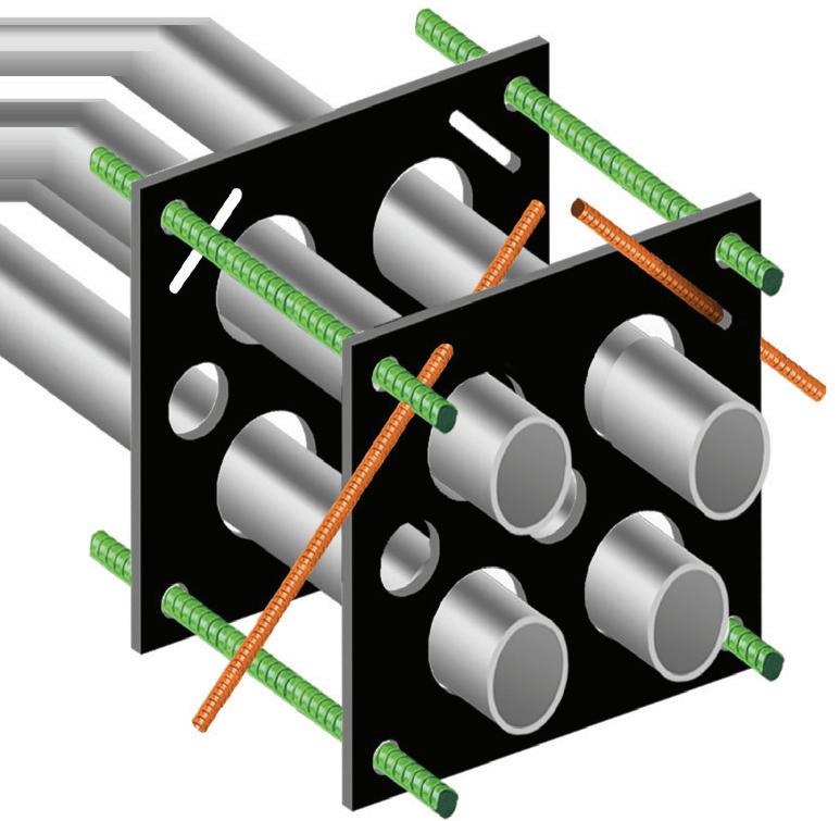
Assemble Conduit Above TrenchNo Workers BelowPrevents Injuries and Deaths. Also Allows Digging a Narrower Trench for Less: Excavation, Concrete, Slurry, Backfill & Shoring.
Staying Ahead of Poor Power Quality
By Ellen Parson, Editor-in-Chief
To kick off 2025, we decided to start the year off with the important topic of power quality, which is always a fan favorite among EC&M readers. Whether you come from the design (engineering), installation (electrical contracting/ electrician) or maintenance (plant facility) side of our audience, providing reliable power solutions to your customers has become a non-negotiable expectation. Not only can poor power quality result in equipment damage or malfunctions, safety hazards, and increased operational costs, but it can also wreak havoc on overall electrical system efficiency or result in the dreaded “D” word no electrical professional ever wants to be responsible for — downtime. Speaking of downtime, we recently ran an online media gallery showcasing the “15 Most Unusual Power Outages of 2024,” thanks to a recent report from Eaton that highlighted the most significant outages of the year in the United States and Canada. Echoing the importance of power outages to the electrical industry specifically as well as society in general, this piece, available at ecmweb.com/55252439, drove significant traffic to our site and sparked active interaction and engagement. As some of the bizarre stories reveal, there’s no shortage of unique culprits behind power interruptions and outages.
Although many of these examples are somewhat extraordinary, there are countless more common instigators that negatively affect power quality. And as power consumption needs inevitably continue to escalate in the future, the need for reliable power becomes even more paramount. According to a new report from Grid Strategies, the current level of growth in electricity demand hasn’t been seen since the 1980s, as reported on marketplace.org in a piece that predicts electricity demand in the United States will increase five times faster over the next five years than originally expected. Another headline from Bloomberg (https://bit.ly/3WciBfd) that recently caught my eye sums up the ongoing power predicament in a pretty clever way: “AI Needs So Much Power, It’s Making Yours Worse.” An additional report from Bloomberg, featured on Data Centre Dynamics’ website at https://bit.ly/4gMCi5p, reveals a strong link between data center proximity and quality of power for consumers. In fact, it states, the “proliferation of data centers supporting AI applications is putting unparalleled strain on the U.S. grid infrastructure and impacting the quality of power delivered to millions of consumers, especially large data center markets like North Virginia.”
According to the “2025 Power and Utilities Industry Outlook” released in December 2024 by the Deloitte Center for Energy & Industrials and available at http://bit.ly/4hqg89l, the United States is “experiencing a surge in electricity demand, driven in part by a confluence of unprecedented electrification, artificial intelligence-driven data center expansion, and a resurgence in industrial reshoring or manufacturing.” In September 2024, the report states that year-to-date electricity demand rebounded with a 1.8% increase, following a 1.7% decline during the same period in 2023 helped by mild weather conditions. A press release from Reuters, based on data from the U.S. Energy Information Administration, shares that sentiment, expecting U.S. power consumption will rise to record highs in 2024 and 2025. EIA projected power demand will rise to 4,086 billion kilowatt-hours in 2024 and 4,165 billion kWh in 2025. That compares with 4,012 billion kWh in 2023 and a record 4,067 billion kWh in 2022.
In an effort to stay ahead of problems stemming from poor power quality issues, electrical professionals will ultimately be the experts industry turns to for answers. That’s why EC&M will continue to cover the latest power quality topics on a regular basis. Don’t miss this month’s cover story, written by PBE Engineers and starting on page 36, which uncovers common power quality misconceptions that can trip up even the most seasoned electrical investigators. “Understanding Power Factor Basics,” by David Colombo, PE, of Power Engineers, LLC, provides a great overview of power factor and why you need to know about it on page 44. To better understand how PV inverter failures may lead to AC power quality issues, turn to the article by William Sekulic and Greg Linder on page 26. Visit us regularly at ecmweb.com/power-quality-reliability for exclusive online coverage of PQ topics as well as through our monthly PQ NewsBeat e-newsletter (sign up at https://bit.ly/4h58a5d), which addresses engineers, commercial and industrial facility personnel, and electric utility managers concerned about power quality & delivery and power supply stability.
WHERE FACILITY CHALLENGES FIND SOLUTIONS
CENTRAL VALLEY
March 19-20, 2025
Modesto Centre Plaza
Modesto, CA
SOUTHERN CALIFORNIA
April 16-17, 2025
Anaheim Convention Center Anaheim, CA
NORTHWEST
May 14-15, 2025
Oregon Convention Center Portland, OR
RENO
August 20-21, 2025
Grand Sierra Resort & Casino Reno, NV
15- or 20-amp, TR & TR/WR $6.00 each/$300 per case of 50 Purchase in bulk to receive additional
10 cases = 5% off 20 cases = 10% off 30 cases = 15% off 40 cases = 20% off 50 cases = 25% off
Vist
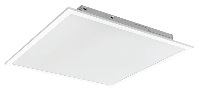
Warehouse Pick Up Price $19.55
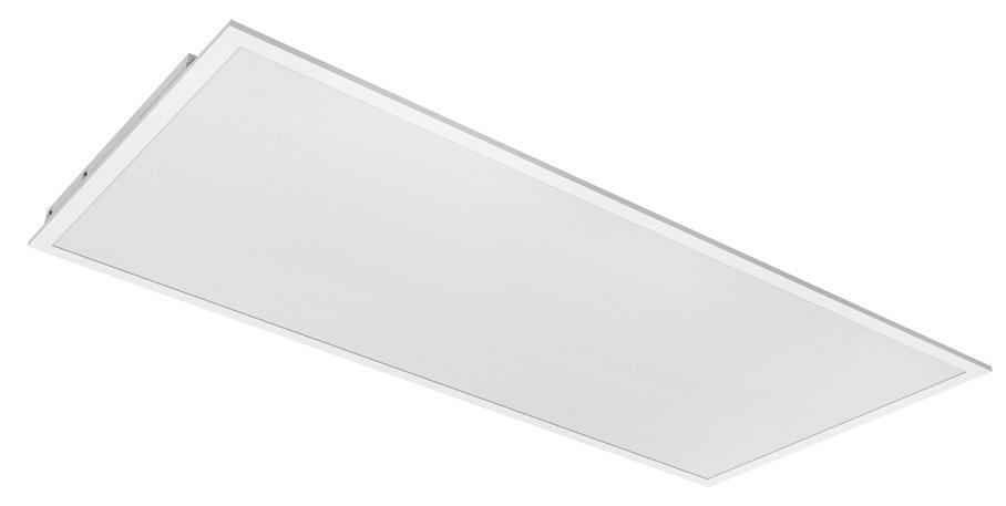
Warehouse Pick Up Price $27.57
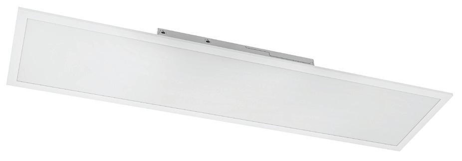
Price $32.57 2X4FT Panel
Product Features:
• Backlit technology that offers even lighting distribution without shadowing.
• Color selectability allows for changing between 3500K, 4000K or 5000K.
• Wattage/Lumen selectable versions: three different lumen outputs in the same product.
• Emergency battery back up optional.
• The range input voltage 120-277V.
• 125 lumens per watt -CRI>80
• DLC Premium/DLC Standard
Areas of Application
The backlit Panels are the high efficiency solution for offices, schools, hospitality and retail areas.
ELECTRICAL TESTING EDUCATION
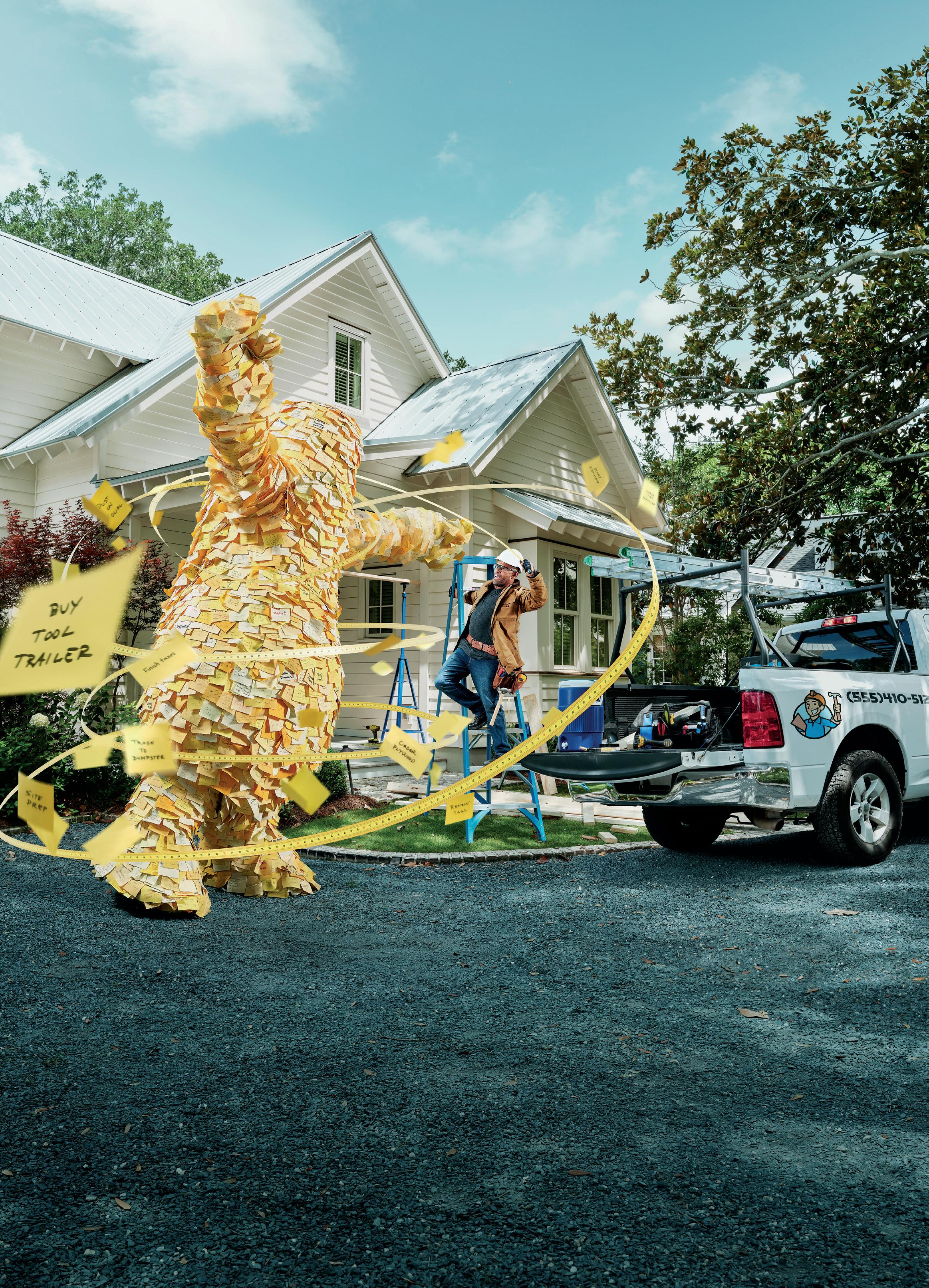
NFPA 70B and the Resurgence of the Electrical Maintenance Program
More than 80% of an electrical maintenance program encompasses taking care of the daily simple things.
By Mose Ramieh III, CBS Field Services
Numerous articles have been written about NFPA 70B in recent months following the recommended practice becoming a standard. All this chatter and renewed interest is coming from the perception — and rightfully so — that failure to perform minimum electrical maintenance could lead to OSHA fines.
I’d like to believe that facilities that did not previously have an electrical maintenance program will now create one out of compliance. Furthermore, I hope this desire for compliance will lead to an observation that the facility has fewer failures and unplanned outages. Then, long-neglected facilities will reach the pinnacle of ongoing commitment to electrical preventive maintenance (EPM) and its benefits for reliability, safety, and lower cost of operation by preventing unplanned downtime.
THE MOST BASIC EPM ACTIVITY: THE LOWLY THERMOGRAPHIC SURVEY
For a long time, I have used a phrase that’s more popular in the physical exercise community: Any activity is better than inactivity. When I have been asked over the years, “What should I be doing for maintenance?” my response has been consistent. If you only have $1 to spend, spend it on an infrared (IR) survey. It is a powerful tool with many benefits that can sometimes go unappreciated.
One of my earliest lessons in the importance of thermographic surveys occurred at a hotel. As a young technician
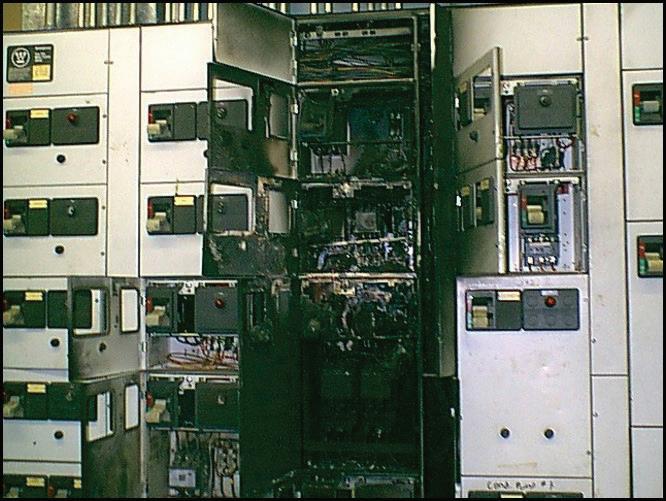
and newly certified thermographer, my assignment was to perform an IR survey on equipment as directed by the client. Things went well as we scanned all the primary service entrance equipment and other portions of the power systems that the client felt were critical. Unfortunately, what was deemed critical didn’t include a motor control center (MCC) in the penthouse. Fast forward a few short weeks to when the hotel suffered a failure in that same MCC.
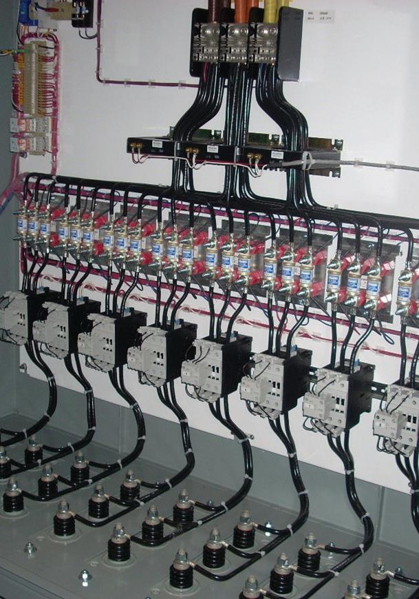
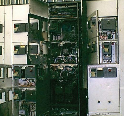
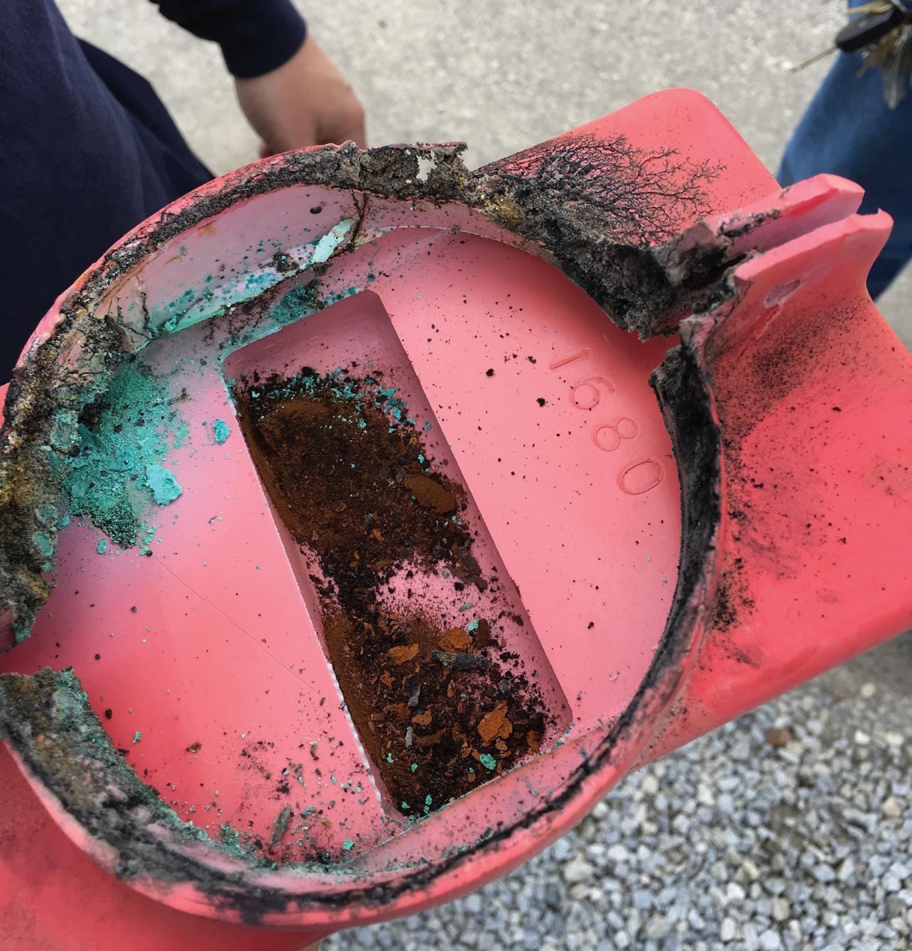
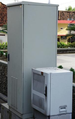
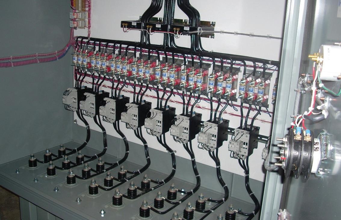
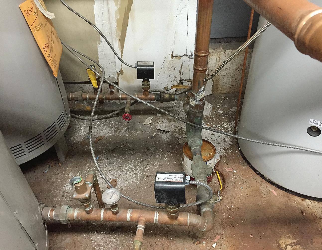
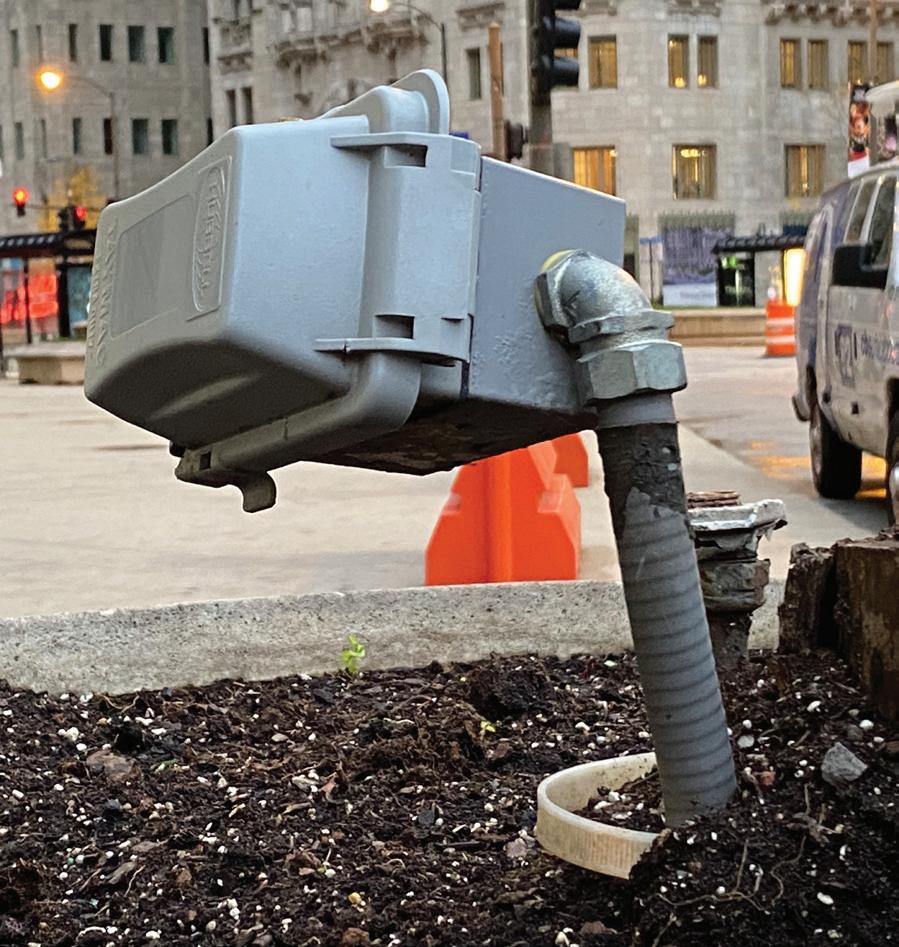
This failure not only destroyed the bucket (Photo 1), which had a loose
connection, but it also created an arc fault that burned bus work inside the gear in half, thereby rendering the entire MCC unsalvageable.
At this point, the criticality of the gear became glaringly obvious. This MCC was the source of power for the hot-water heating system. Imagine the difficulty created when an entire hotel of guests had no hot water for their morning showers. It created a difficult conversation for myself and the facility engineer. We both learned a valuable lesson. Never leave a job site until every
Photo 1. This motor control center was destroyed by a loose connection that became an arc fault.
ELECTRICAL TESTING EDUCATION
reasonable attempt has been made to scan everything inside the facility.
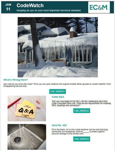
CodeWatch
This e-newsletter, published four times per month, is dedicated to coverage of the National Electrical Code. The content items are developed by well-known Code experts.
CodeWatch promises to:
• Explain how to properly apply the Code
• Test your knowledge of the Code
• Provide information on upcoming Code-related seminars and shows
• Offer Code quizzes and real-world Code violations
Subscribe Today
See all of our EC&M e-newsletters at www.ecmweb.com
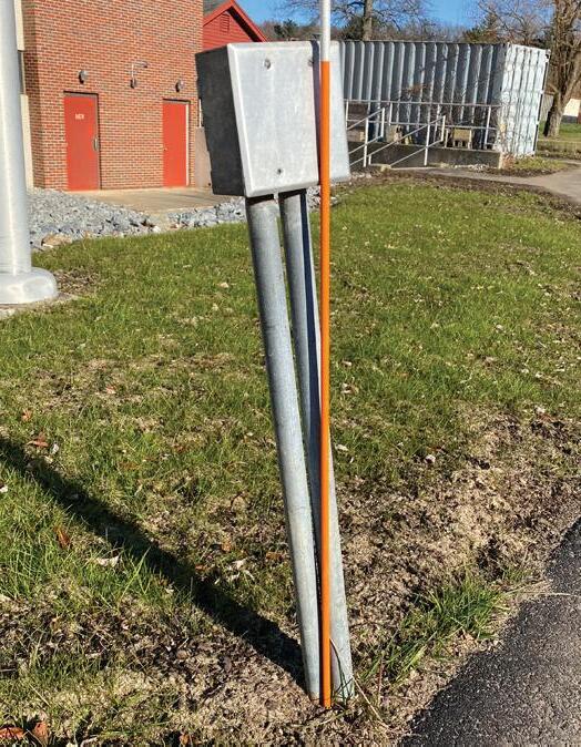
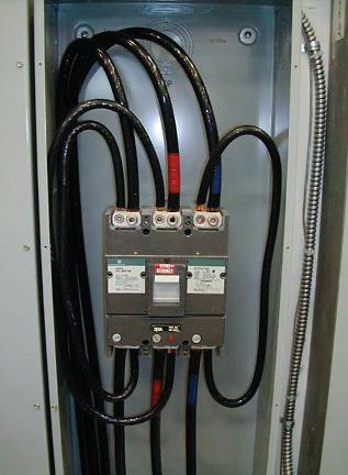
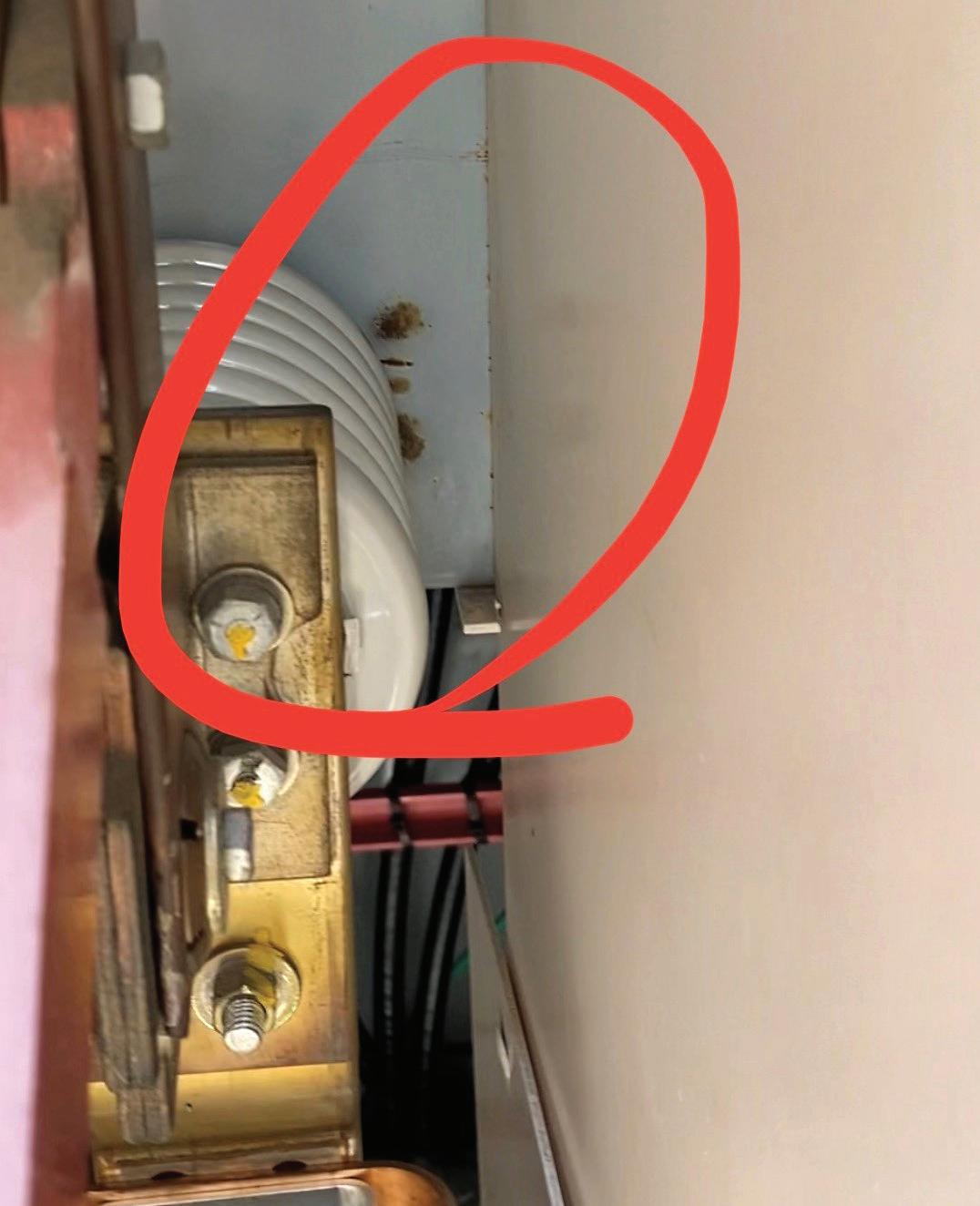
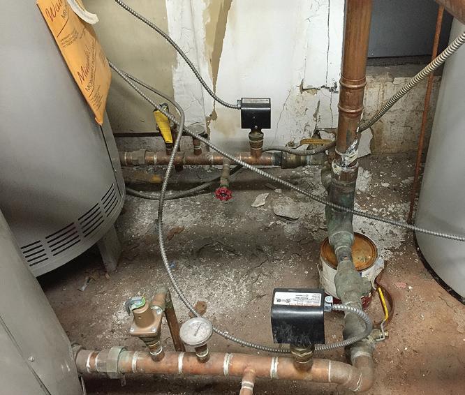
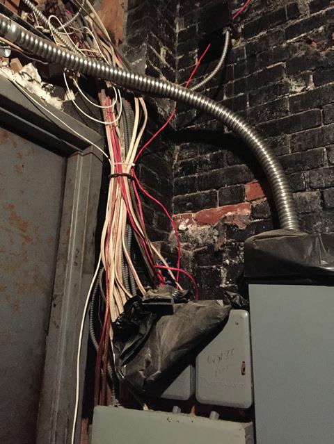
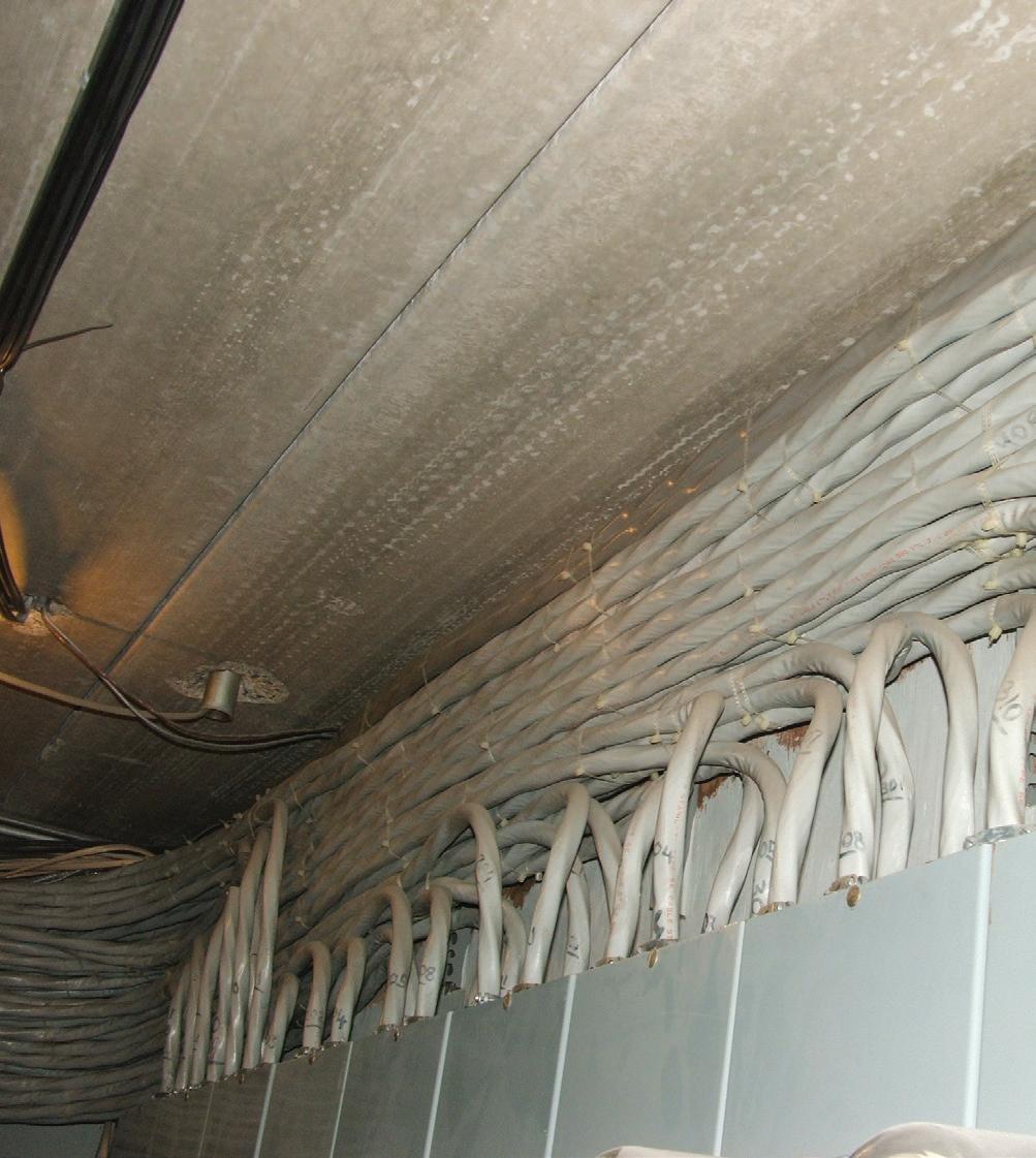
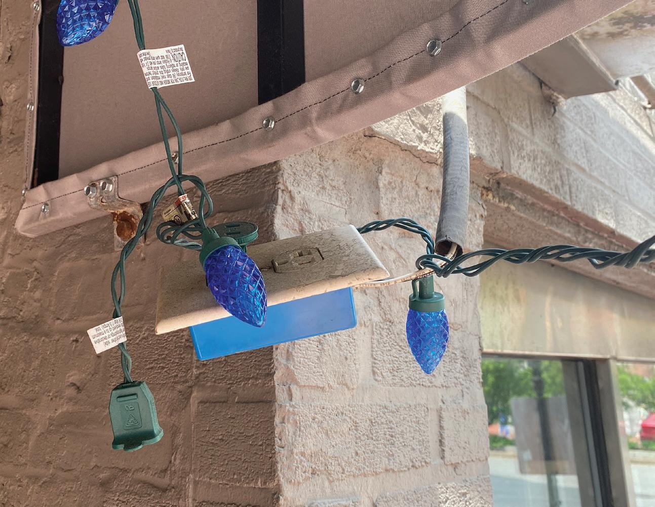
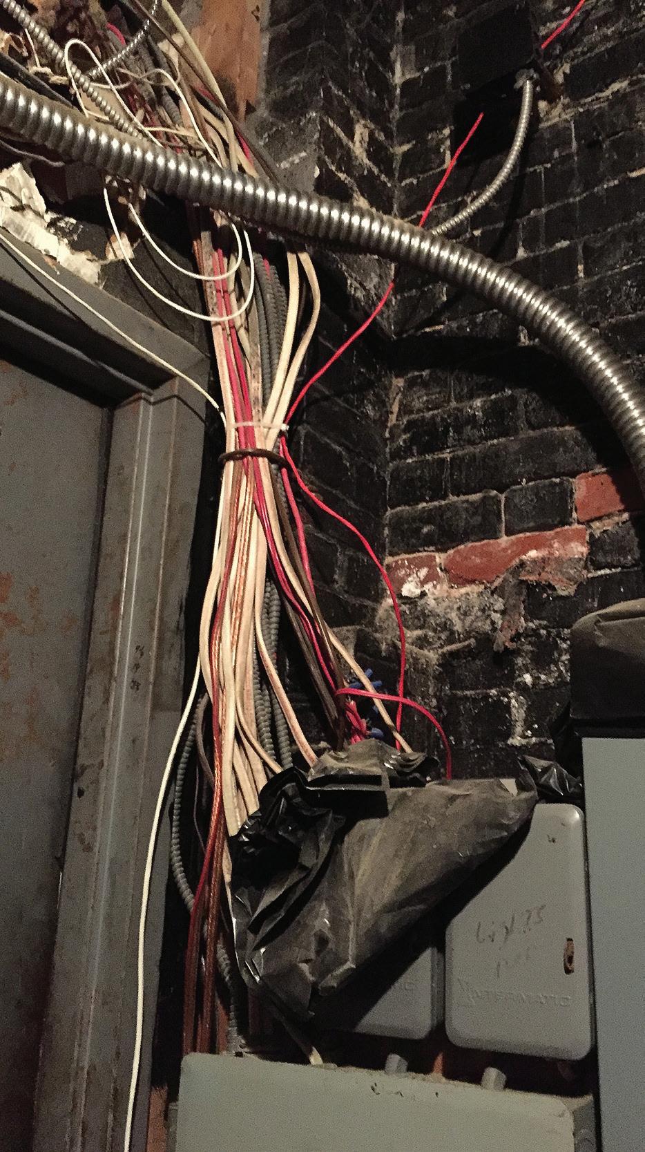
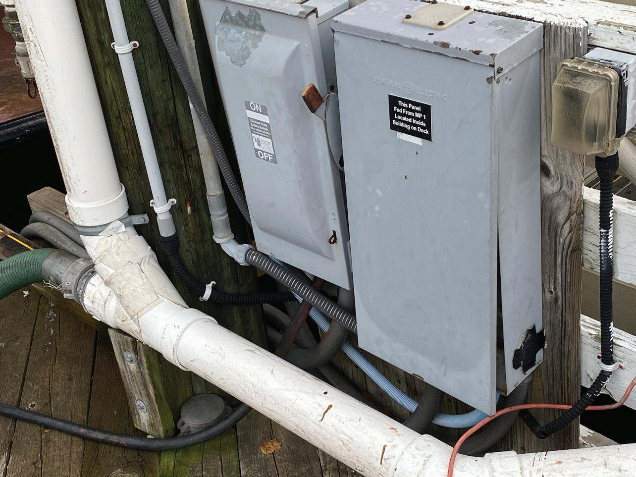
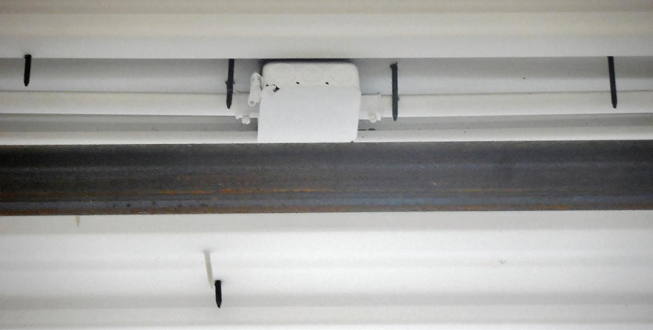
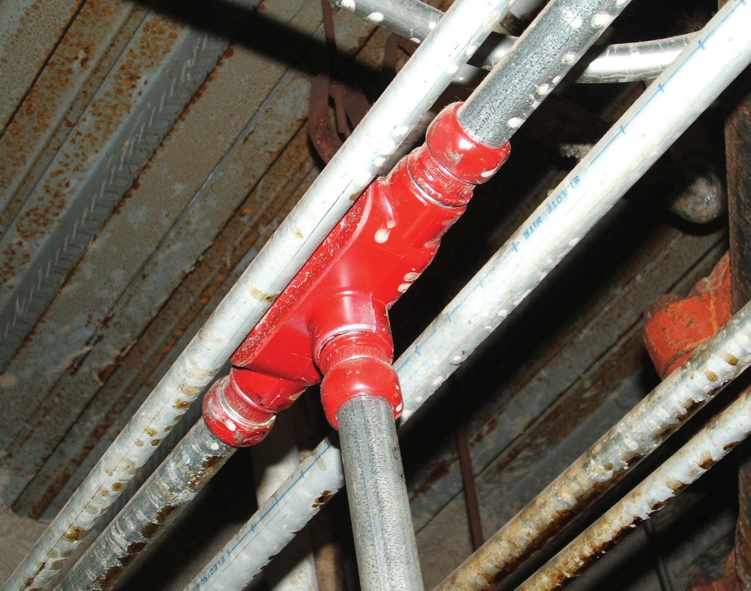
A second benefit of thermographic inspections is that other safety hazards and National Electrical Code (NEC) violations can be found even in equipment without a thermographic issue. For example, a fuse that is replaced with a short section of copper pipe or a set of jumpers installed (Photo 2) by a well-intentioned, but reckless, electrical contractor can create a major safety issue.
Yes, that picture was taken inside a facility; it was not staged. After immediately bringing this to our customer’s attention, we heard a story of how this particular breaker had been tripping repeatedly, causing unacceptable outages. The fix, which I’m sure was never openly discussed, was to install jumpers from line to load and effectively eliminate the breaker. This has been a powerful lesson as to the importance of always testing for the absence of voltage after opening a breaker and before beginning work.
Electrical Testing Education articles are provided by the InterNational Electrical Testing Association (NETA), www.NETAworld.org. NETA was formed in 1972 to establish uniform testing procedures for electrical equipment and systems. Today the association accredits electrical testing companies; certifies electrical testing technicians; publishes the ANSI/NETA Standards for Acceptance Testing, Maintenance Testing, Commissioning, and the Certification of Electrical Test Technicians; and provides training through its annual conferences (PowerTest and EPIC — Electrical Power Innovations Conference) and its expansive library of educational resources.
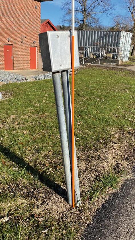
WHY IS MY MAIN SWITCH OPENING?
Facilities that seldom do maintenance could experience unexpected operations of protective devices after proper maintenance is completed. One such example was a bolted pressure switch at a plant we serviced. Many technicians have experienced a moment of dread when you push the trip button on a bolted pressure contact switch with all of your might and nothing happens — the switch doesn’t open. When this happens, you know you will probably not be going home early. But it happens, and we all know it’s a possibility anytime we work on a bolted pressure switch of any type.
The solution revolves around penetrating oil, some patience, and the occasional tug-o-war with a strap to pull the switch open. Please note that this work must always be performed on equipment in an electrically safe condition. With any luck after a good bit of cleaning and proper lubrication, the switch typically can be restored to operational status and closes properly. It is while following this type of repair that a new form of problem can occur.
After the maintenance and repair of the bolted pressure contact switch, our client called us in a panic. The switch had opened unexpectedly and could not be reclosed. They wanted us on site right
Photo 2. Jumpers installed to the line and load side of a breaker create a safety hazard.
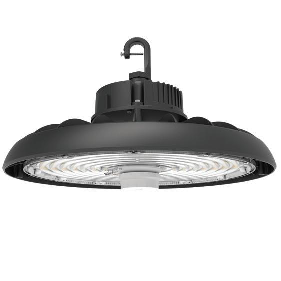
UFO11
100/120/150w Selectable
35/40/50k Selectable $45.00 Each
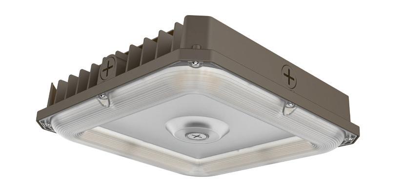
Canopy
60/80/100w Selectable 35/40/50k Selectable $60.00 Each
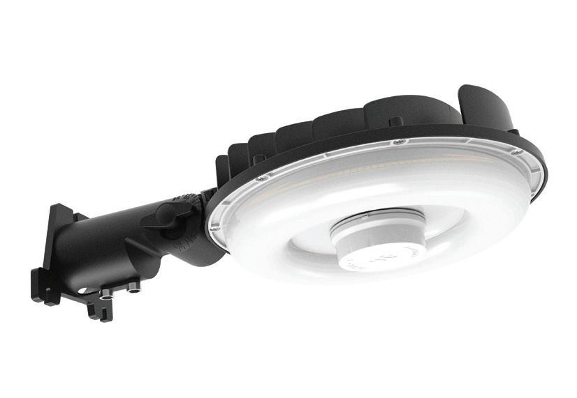
Barn Light
60/80/100w Selectable 35/40/50k Selectable $44.00 Each
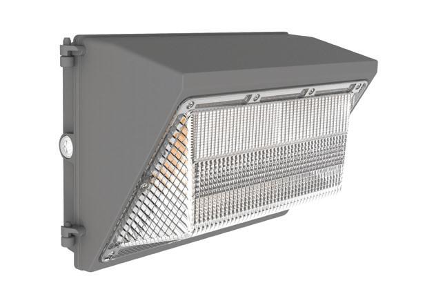
Wall Pack with Photocell
90/100/120w Selectable 35/40/50k Selectable $67.00 Each Need More Information? Call us at 855-624-6258 Or find us on the web at https://tntind.us/
Prefer to buy in bulk? Check out these discounts!
50 pcs = 5% off
100 pcs = 10% off
150 pcs = 15% off
200 pcs = 20% off
250 pcs = 25% off
ELECTRICAL TESTING EDUCATION
PQ Newsbeat
If you’re an engineer, commercial or industrial facility manager, or electric utility employee concerned about the quality and reliability of power delivery, this e-newsletter (sent out monthly) is for you.
Topics covered include:
• Power quality
• Voltage sags & swells
• Transients
• Harmonics
• Power factor
• Test & measurement techniques
Subscribe Today
See all of our EC&M e-newsletters at www.ecmweb.com
away to close the switch and determine the reason it had opened.
As I drove up to the plant, I noticed that many buildings in the surrounding areas were also in the dark. As it turned out, the local electric utility had lost power, and the undervoltage relay associated with the switch had done its job and opened the switch. I explained to the client that the system had worked properly and that once utility power was restored, we would be able to close the switch. To roughly quote the property manager, “We have had numerous utility outages over the years and never needed to reclose the switch!”
Stuck switches are a great opportunity to discuss the importance of maintenance to avoid the normalization of deviation with your client. Once a switch is functioning mechanically, it is important to verify and demonstrate the ground fault and undervoltage/ loss of phase relay operations for your customer.
THERE MUST BE A REASON FOR THIS LOW READING
Two jobs come to mind where a simple test resulted in finding a major issue that wasn’t directly associated with our scope of work. The scope of work involved testing WLI-style medium-voltage air switches. In the standard procedures I have used over the years, disconnecting the incoming feeder cable is not part of the work. My thoughts are that disconnecting the cable adds unnecessary time and additional risk to the job (human performance issues to get them bolted back up).
Instead, test the switch with the cables connected. If it meets the minimum value required by ANSI/NETA MTS–2023, Standard for Maintenance Testing Specifications for Electrical Power Equipment and Systems, move on. Note: This method requires communication and flagging of the opposite cable ends for safety.
Utilizing this method on these two jobs, we noted insulation resistance
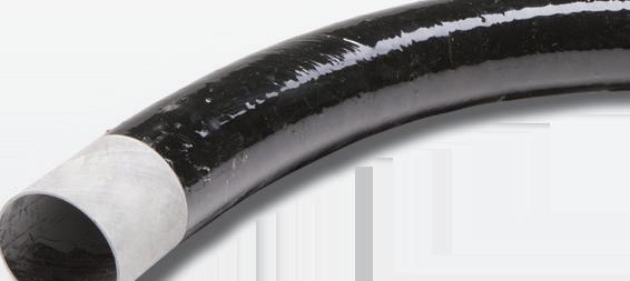
Photo 3. Evidence of partial discharge was not visible until the insulator was removed.
(SEE ABOVE)
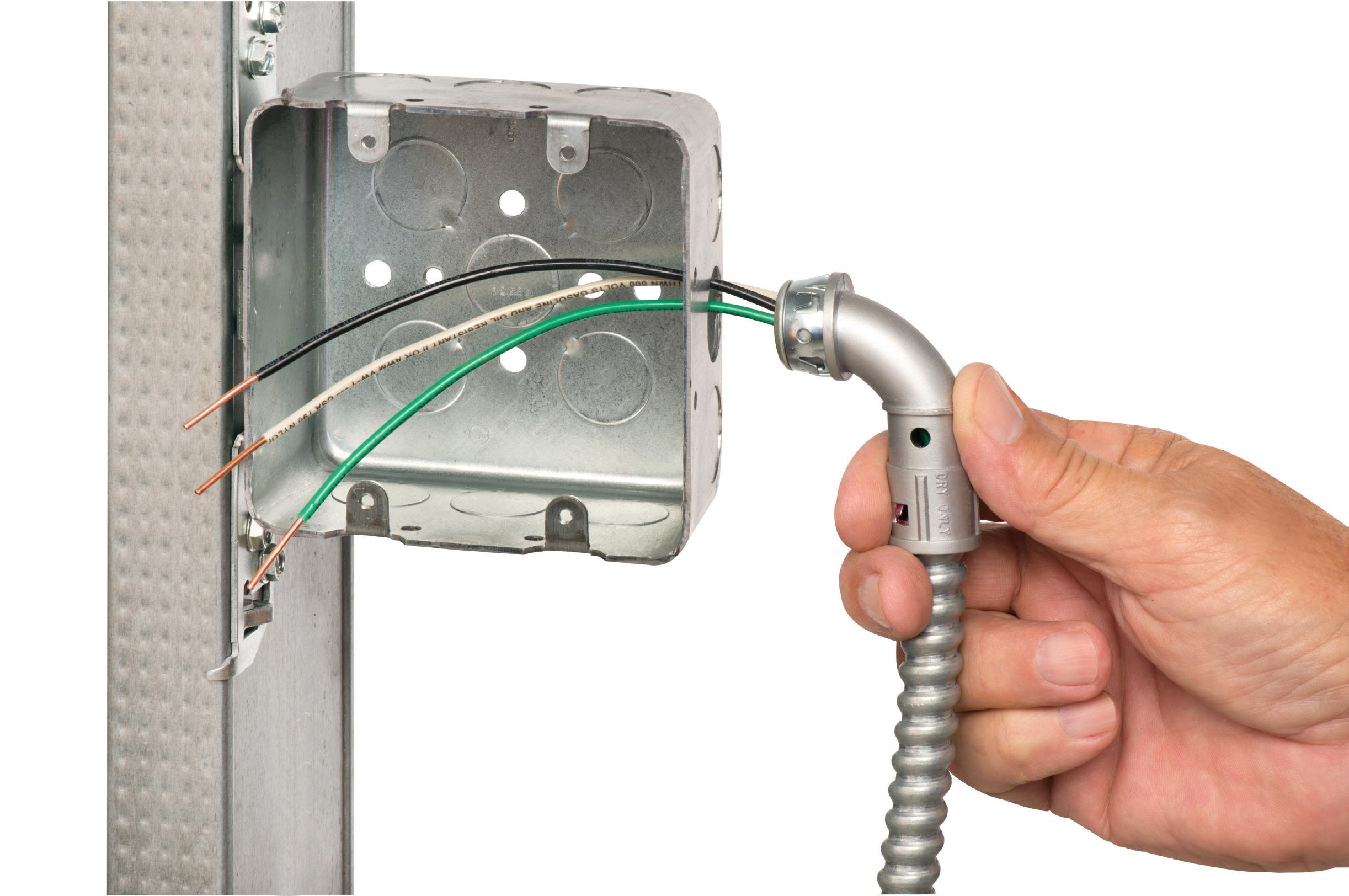
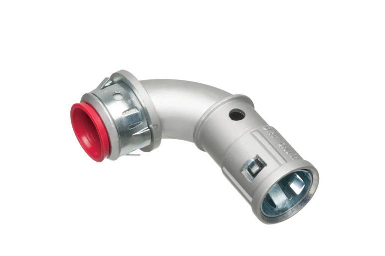
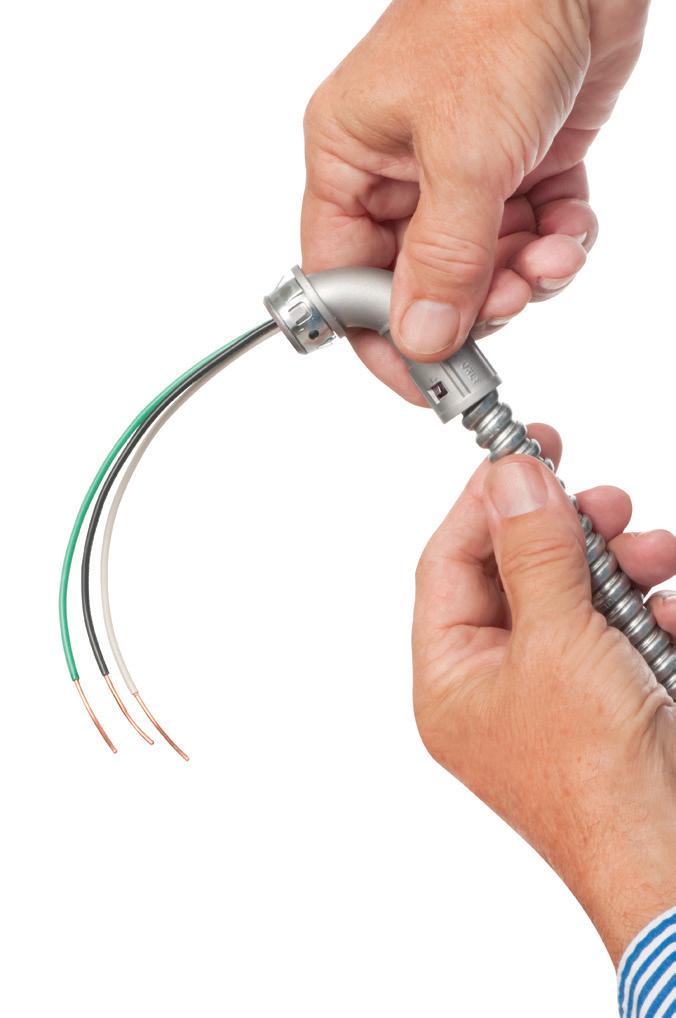
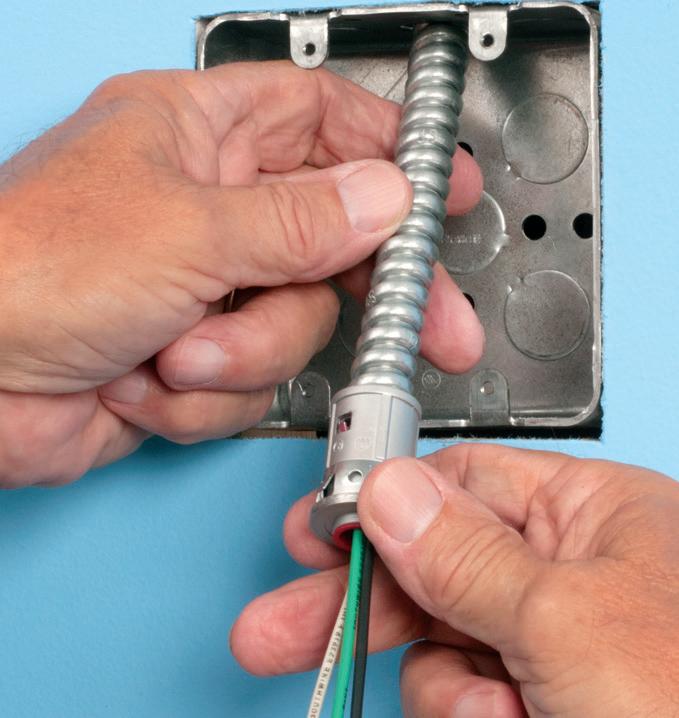
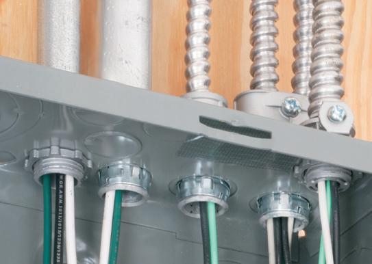
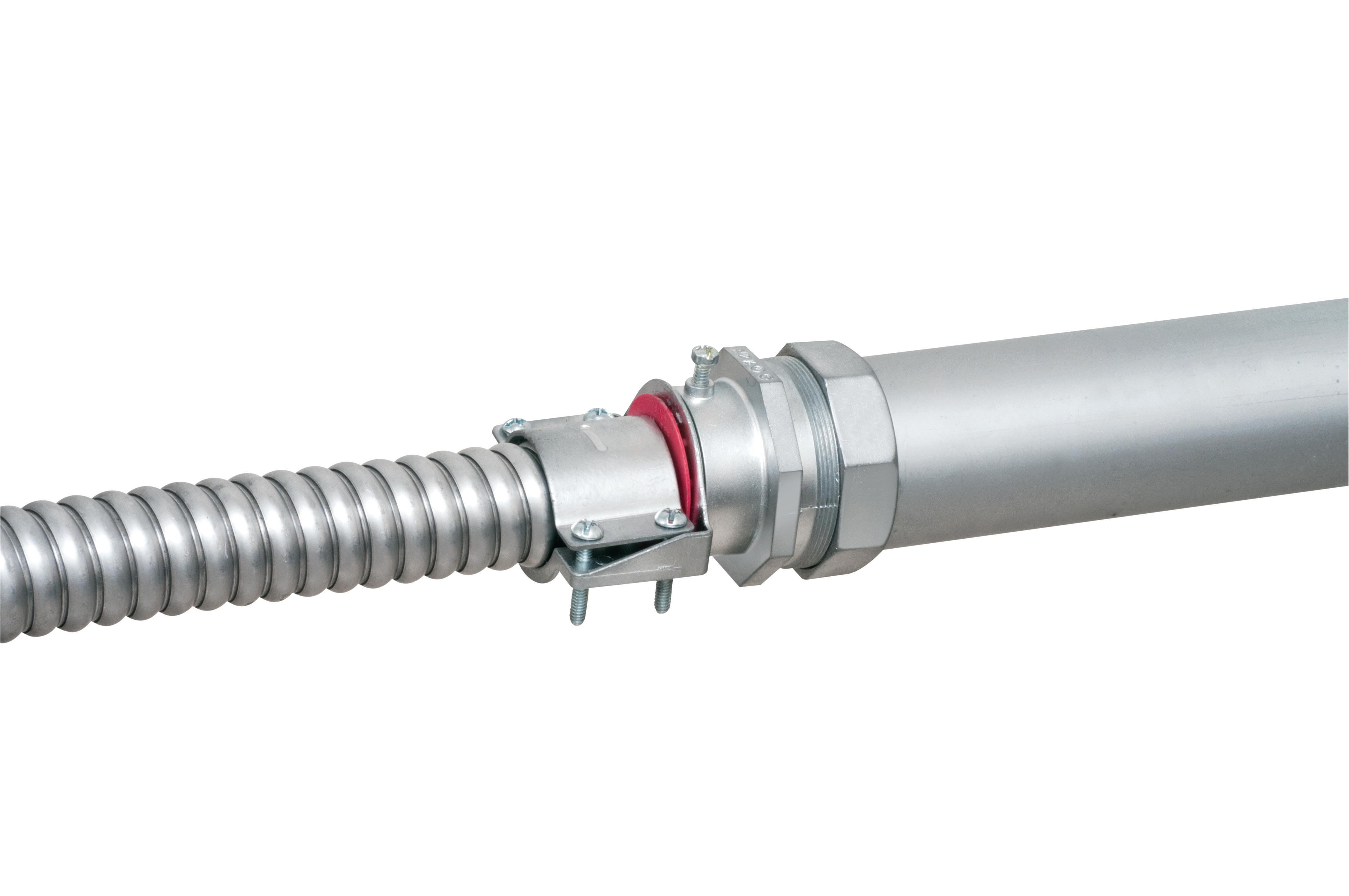
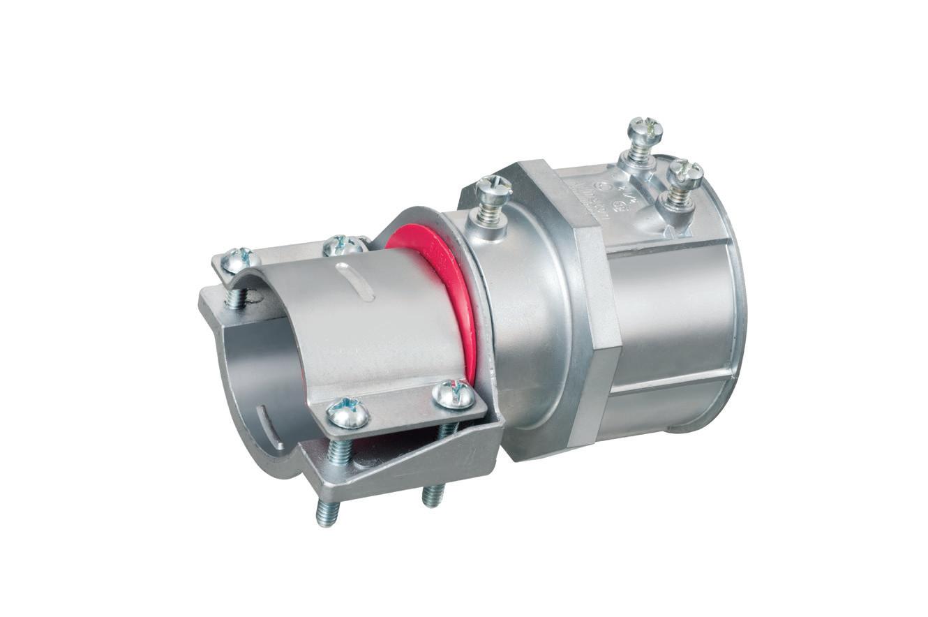
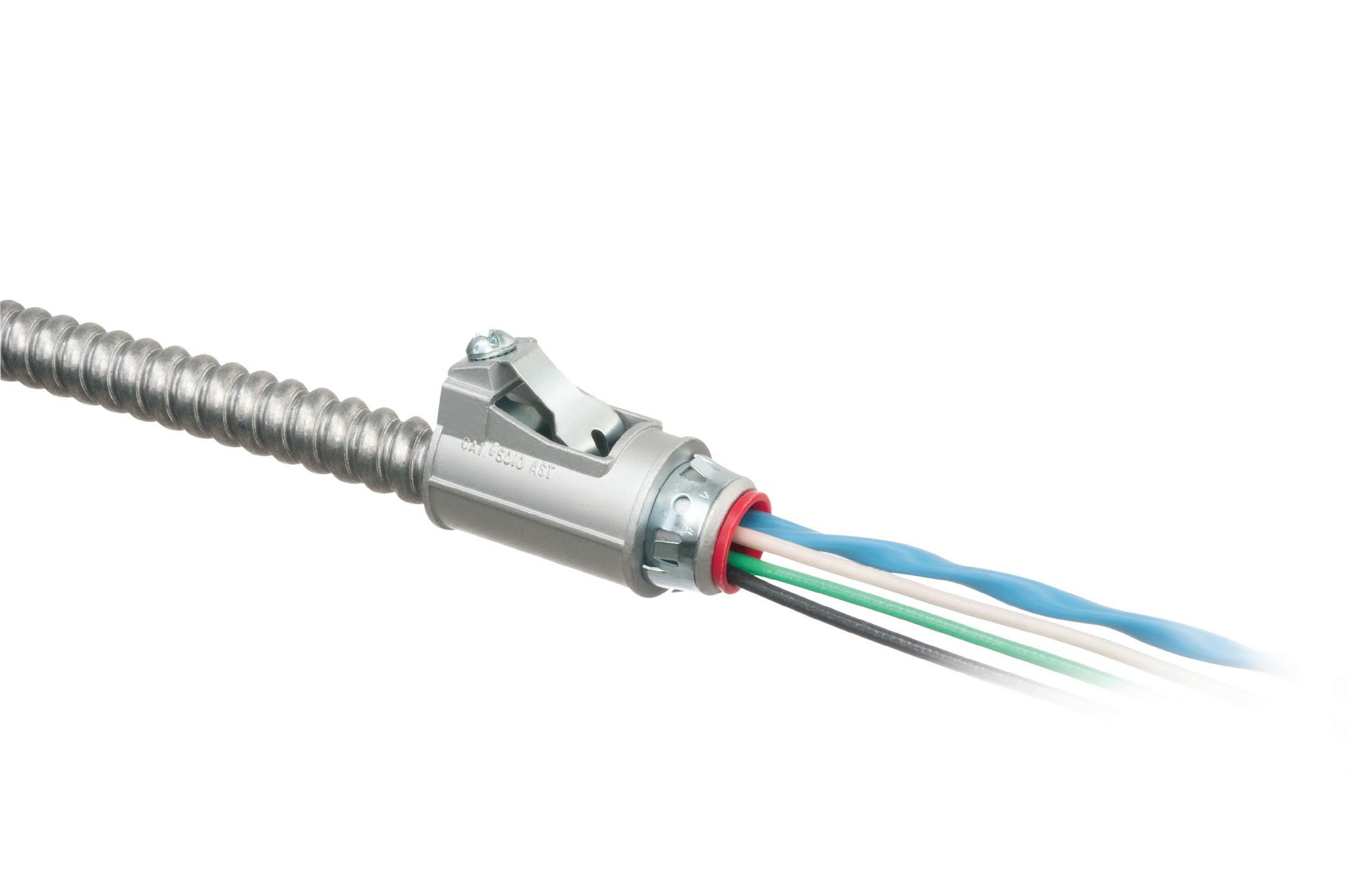
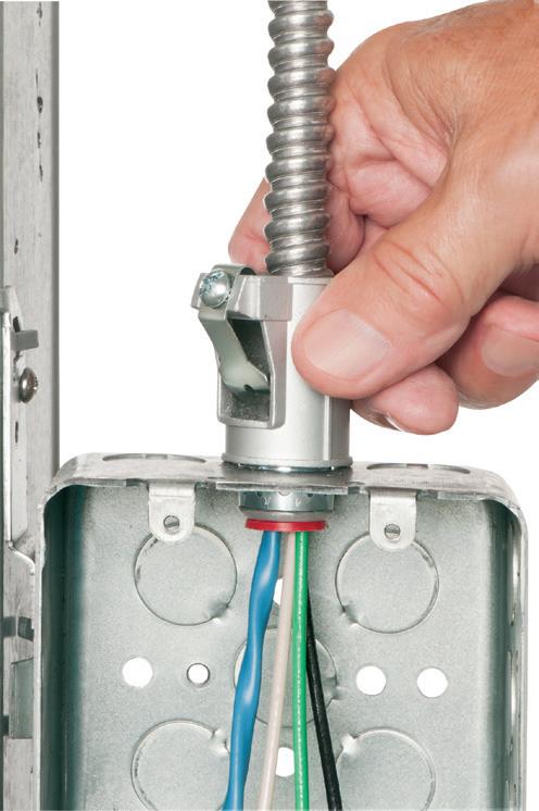
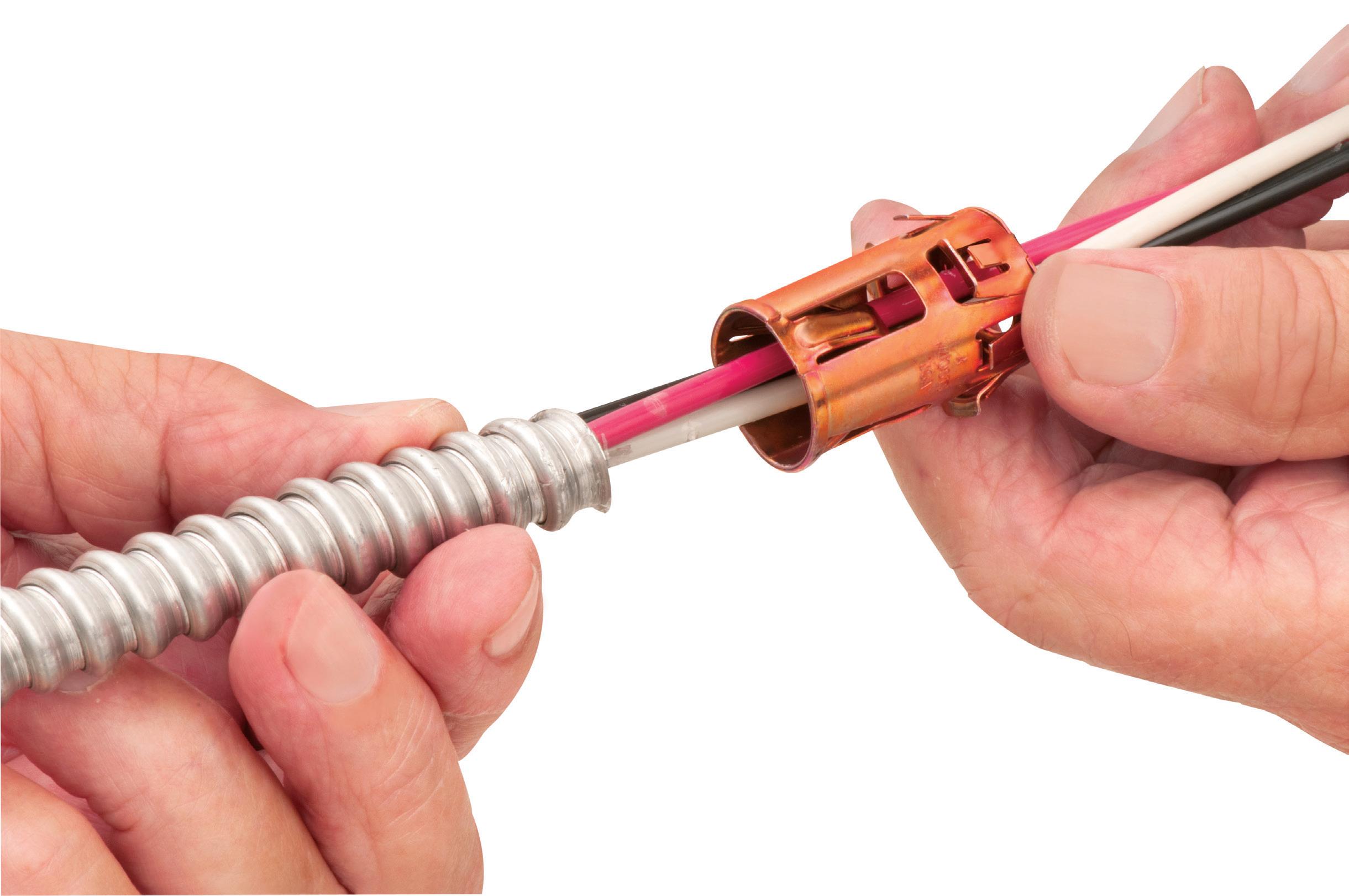
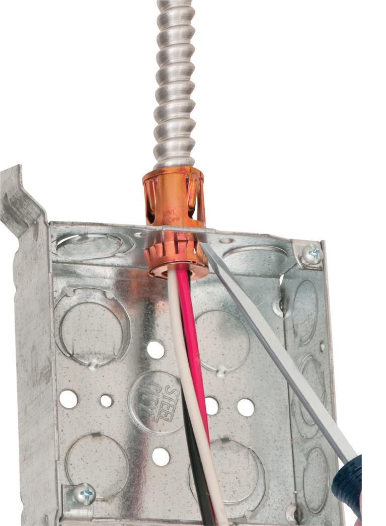
• Easy snap-in cable installation Save time over 90° 2-screw MC Connectors at same cost per connector
• Handles widest range & variety of cables: 14/2 to 10/2 AC, MC, HCF, MC continuous corrugated aluminum cable, MCI-A cables (steel & aluminum), AC90 and ACG90
• Fast, secure installation...No pullout
• Easy to remove from box...reusable
40900ST
ELECTRICAL TESTING EDUCATION
ElectricalZone
This weekly e-newsletter offers subscribers a unique and inside view into the most important trends, technologies, and developments taking place within the electrical industry.
Topics covered include:
• EC&M videos & podcasts
• Market forecasts and analysis
• Code Quiz of the Week
• Online-only feature articles
• Late-breaking industry news
Subscribe Today
See all of our EC&M e-newsletters at www.ecmweb.com
readings on one phase of the switch on the incoming cable side that were well below the recommended values in ANSI/NETA MTS. When this occurs, you must disconnect the cable to determine whether the issue is the switch or the cable/upstream equipment.
As you might imagine, the low reading followed the cable and connected upstream equipment; it was not a problem at the switch. At this point, valuing the client and wanting to ensure the issues are found, it made sense to present this information to the client and request permission to test additional equipment that was outside of the original scope of work. With approval from the client for the additional work, we disconnected the cable at the next termination point upstream. With the cable isolated, we tested the cable only to learn that it was not the cable was not the source of the problem.
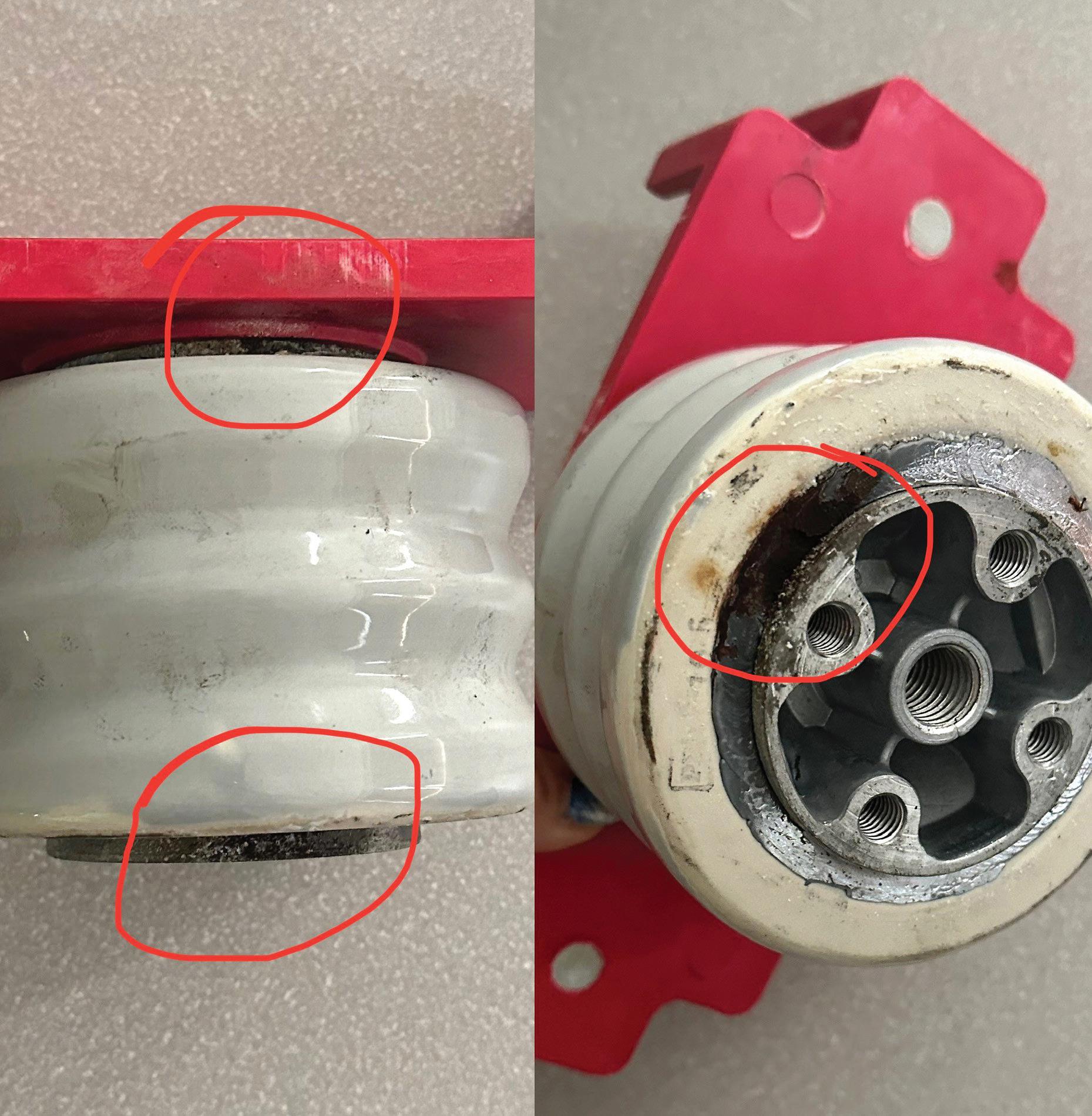
In both cases, our troubleshooting attention turned to the main
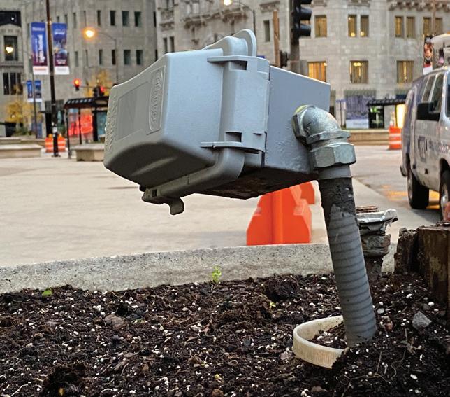
switchboard. We tested the gear to confirm it was on the gear side. It was. Initial inspection revealed no evidence for the low reading, so we began the work of taking things apart. All of this time and work to isolate the issue now paid off as boots were removed and stand offs were unbolted from bus work to reveal partial discharge and corona damage (Photo 3 on page 14, Photo 4, and Photo 5 on page 18). One simple test — and the tenacity to chase down a failing reading — headed off a potentially catastrophic failure.
While all test results might pass on this switch, a qualified technician would recognize this as evidence of partial discharge, which is often related to moisture building up in the switch and typically is directly related to the failure of the space heater in the gear. Left uncorrected, this seemingly minor issue can cascade into violent failure. Be vigilant during your routine inspections.
Photo 4. Corona damage on the bus work and insulating boot made identifying this issue easier to spot.
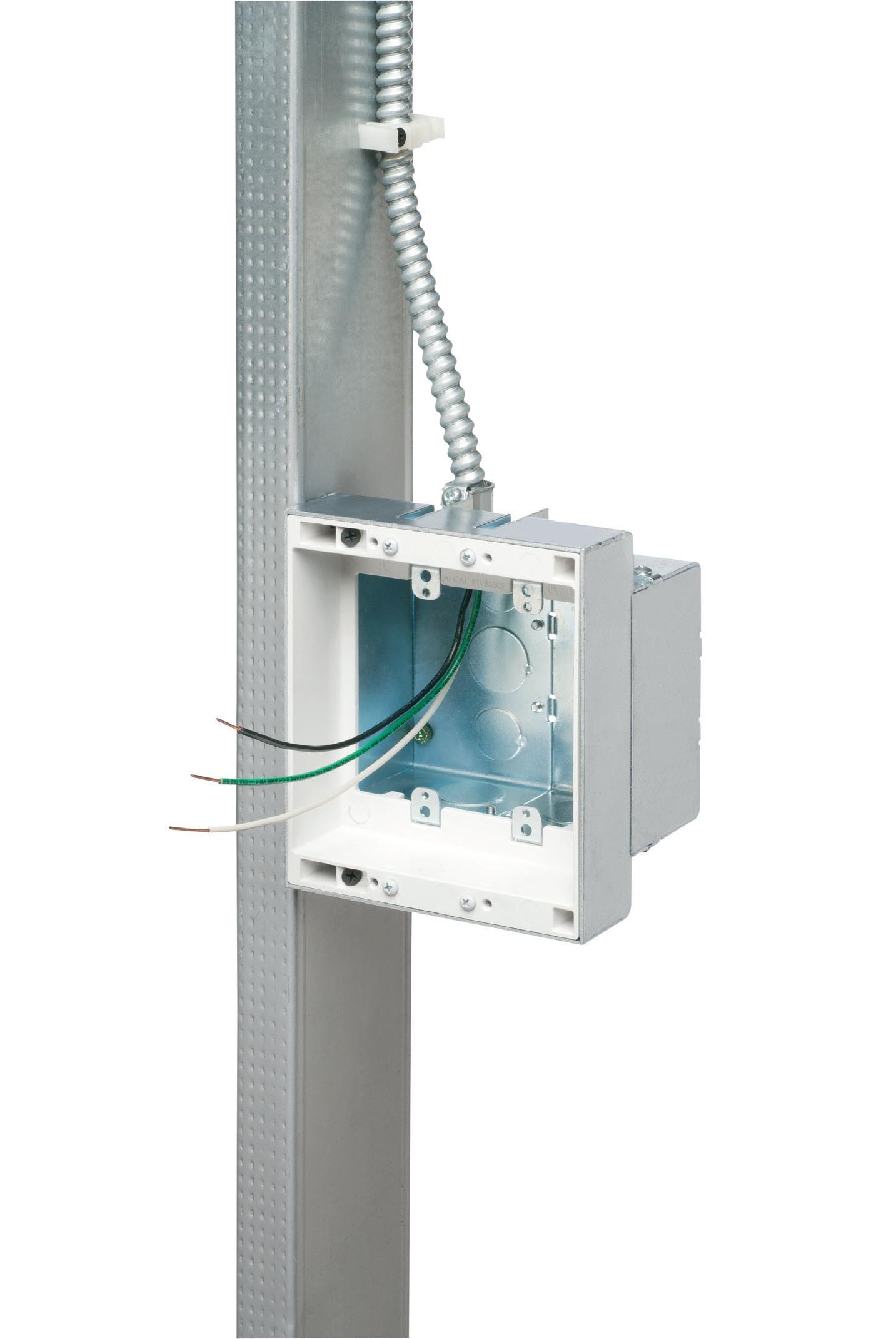
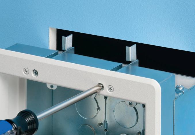
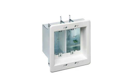
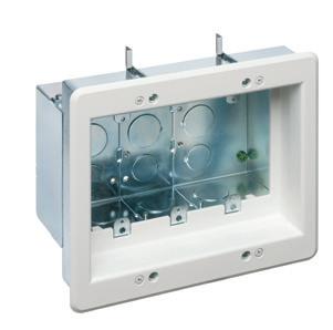
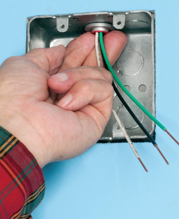
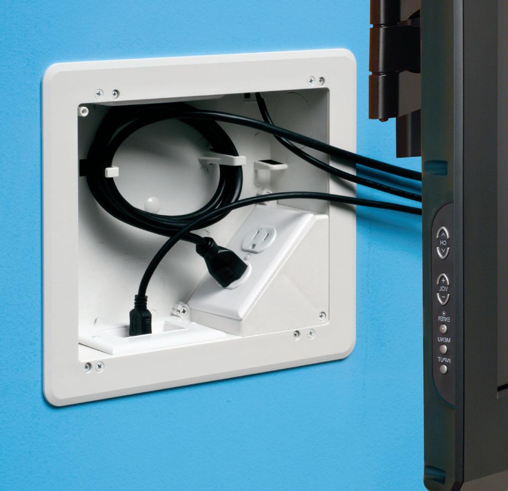
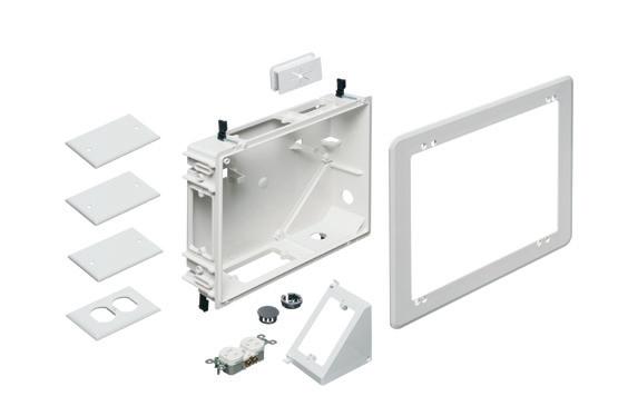
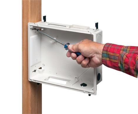
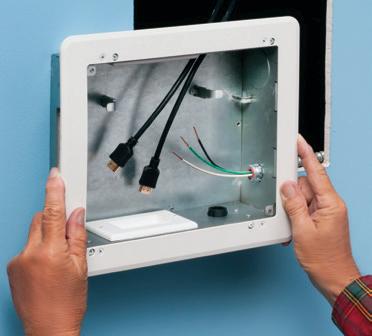
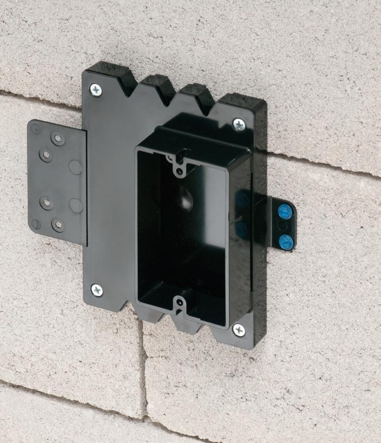
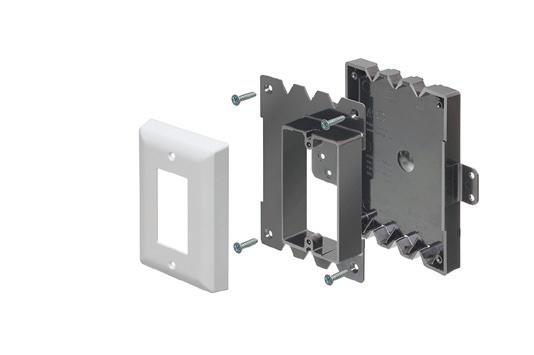
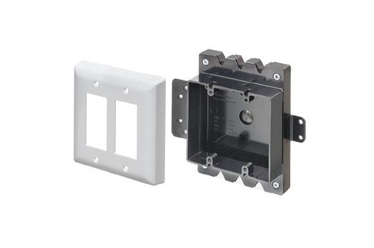
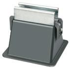
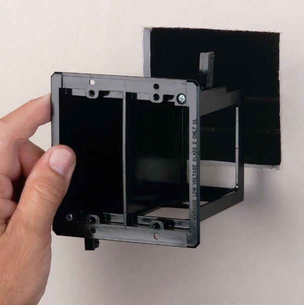
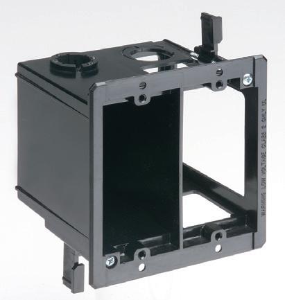
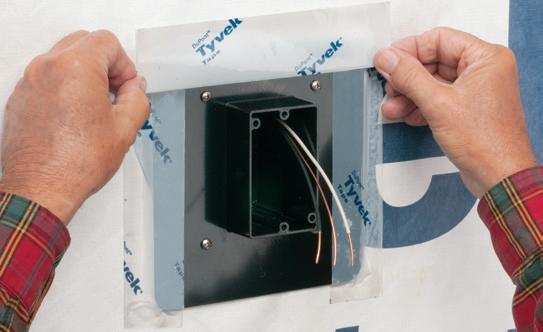
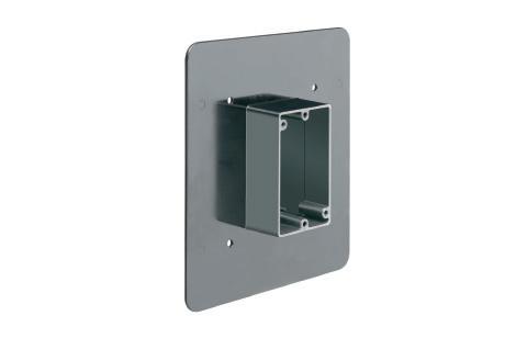
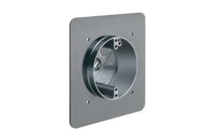
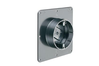
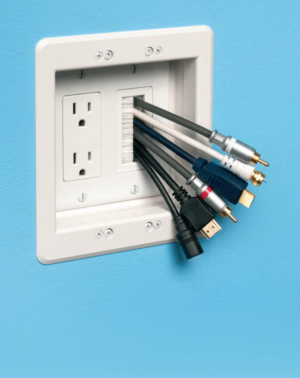
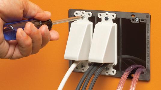
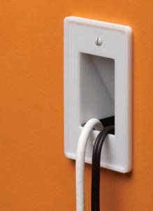
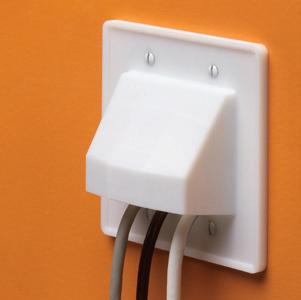
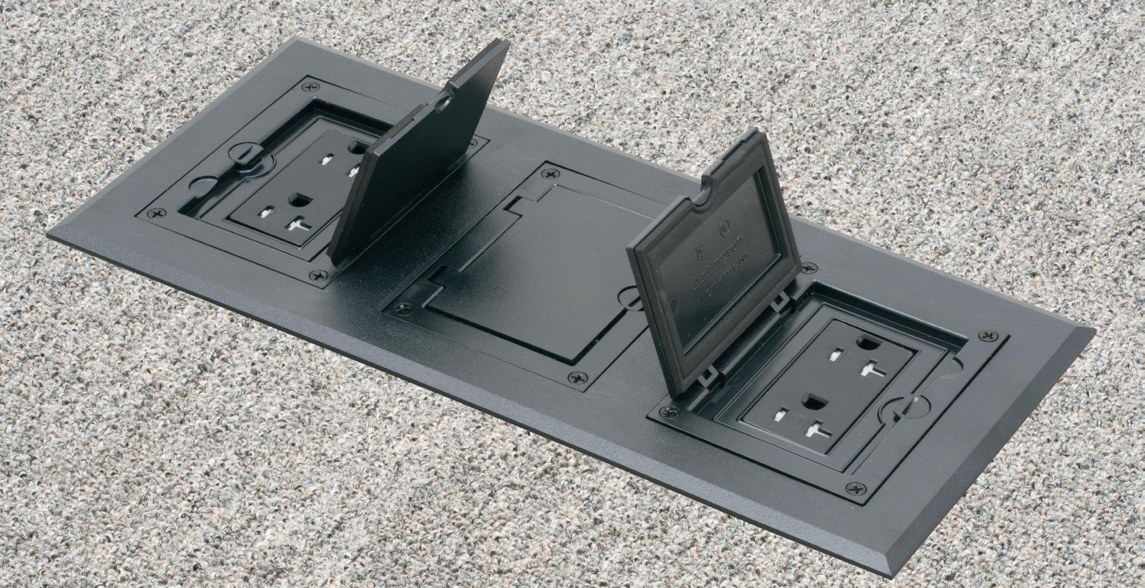
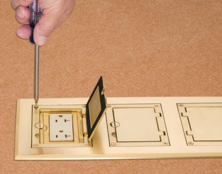
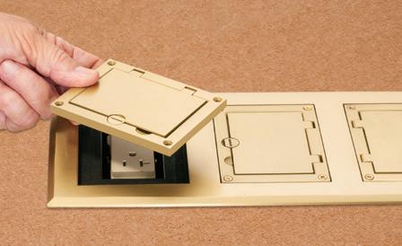
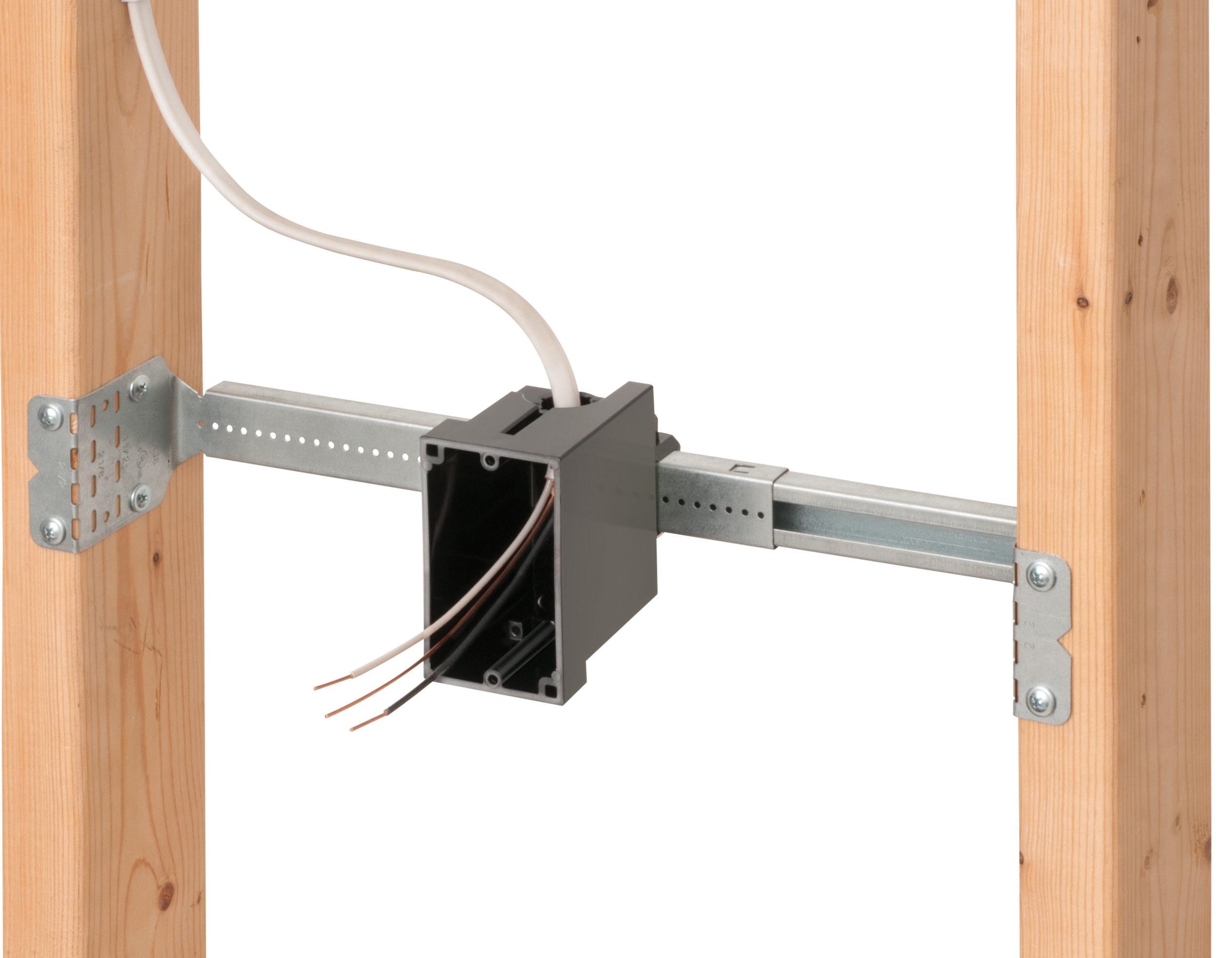
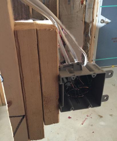
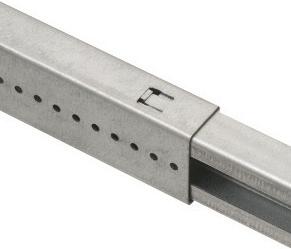
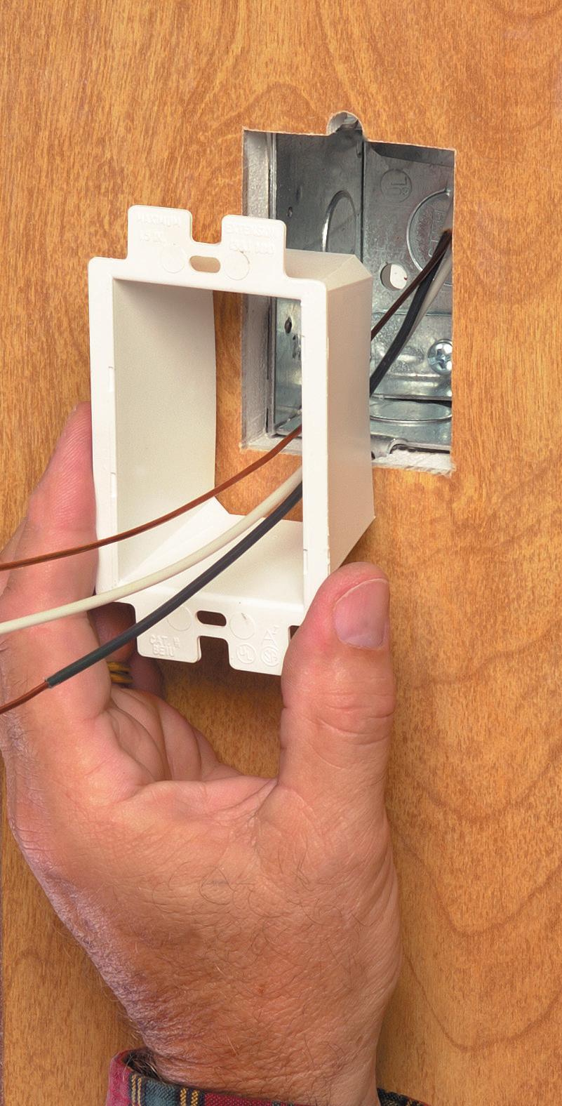
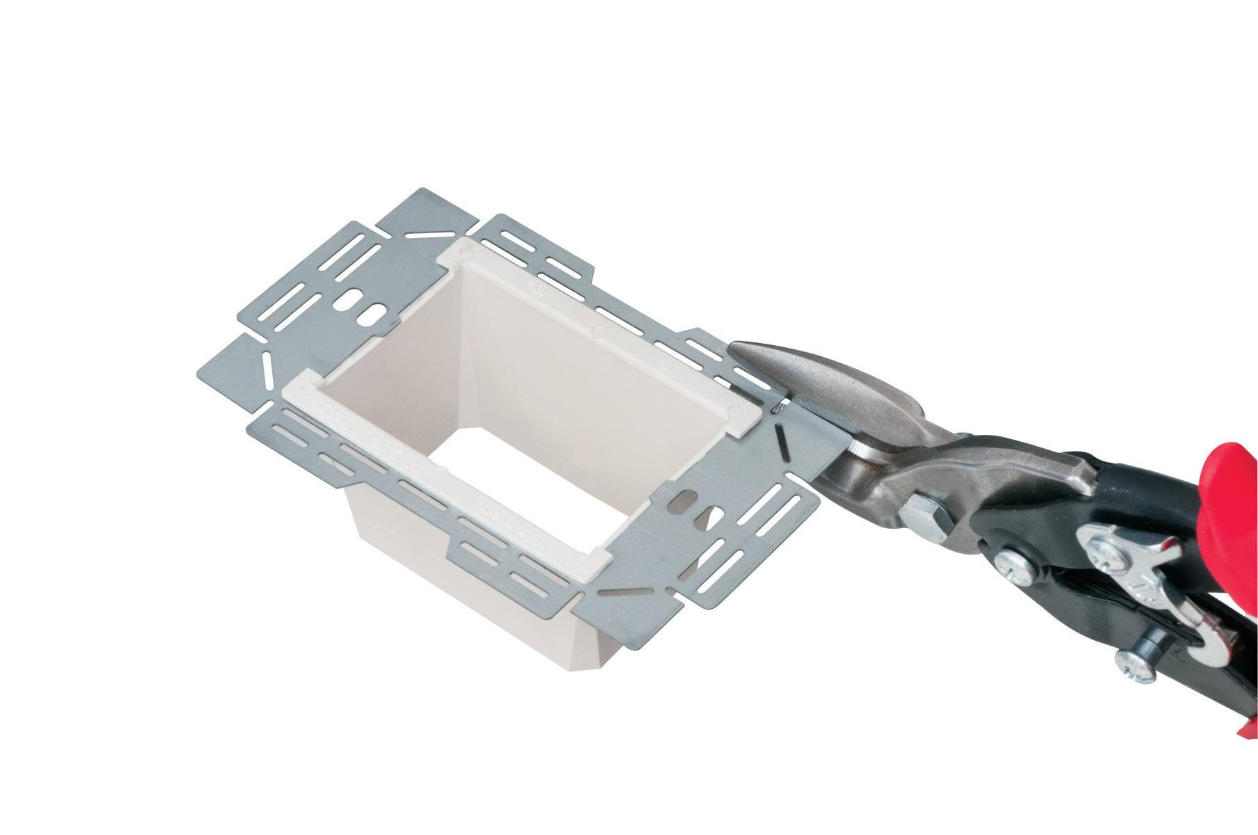
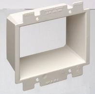
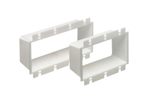
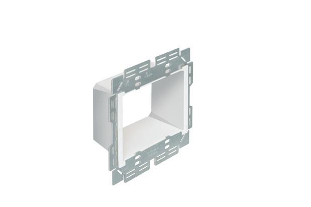
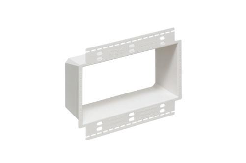
Arlington’s recessed STEEL combination power/low voltage TV BOX™ is the best way to mount an LED or Hi-Def TV flush against a wall.
TV BOX provides power and/or low voltage in one or more of the openings. Plugs and connectors stay inside the box, without extending past the wall.
Designed for use in new or retrofit commercial construction where metal raceway is used, we have a STEEL TV BOX for almost any application!
• Steel box; non-metallic paintable white trim plate
• Easy, secure installation
• Optional covers
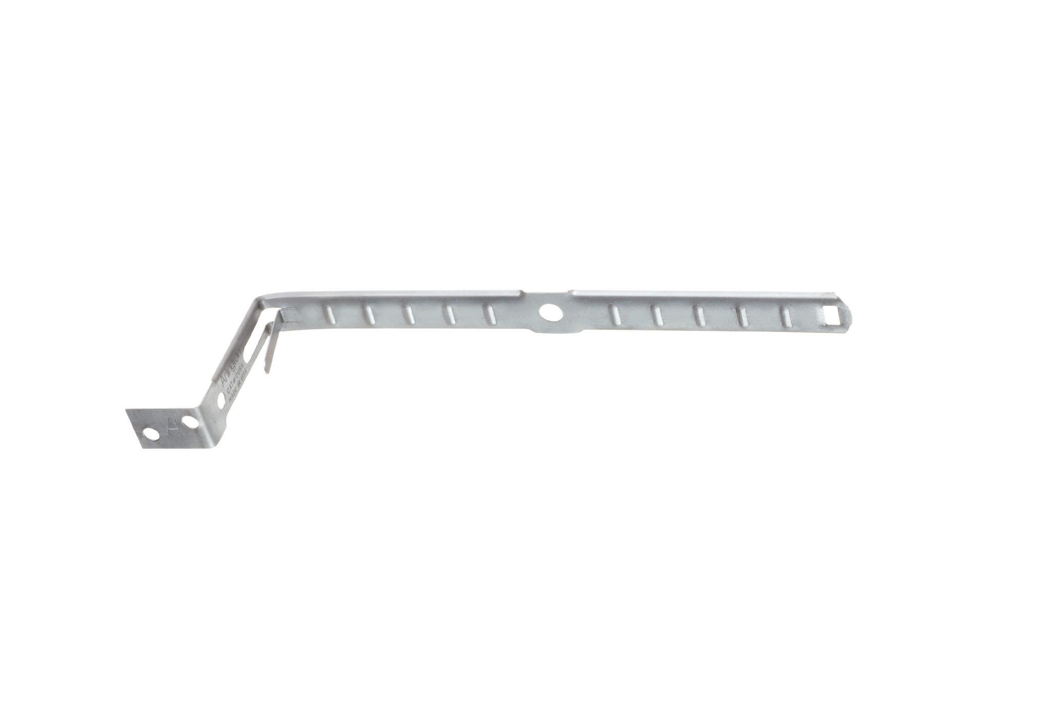
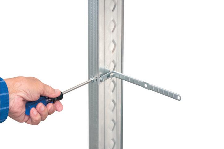
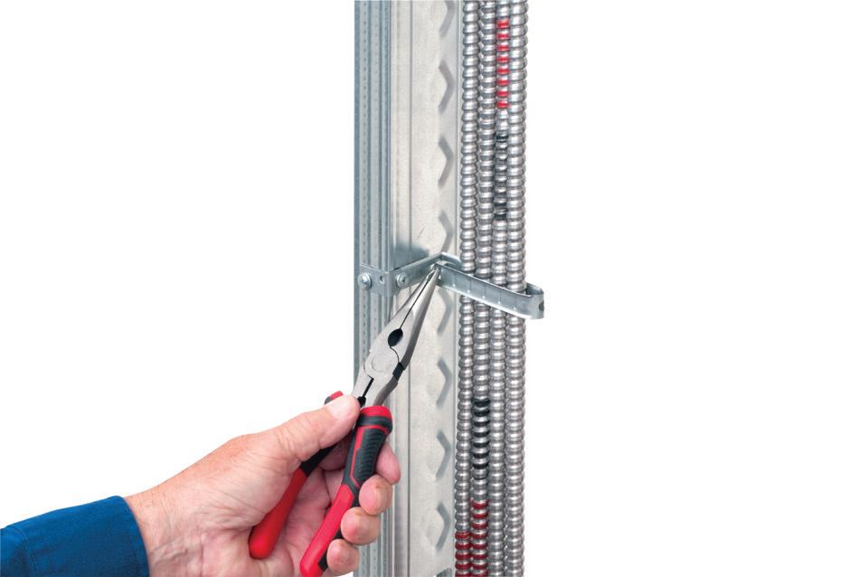
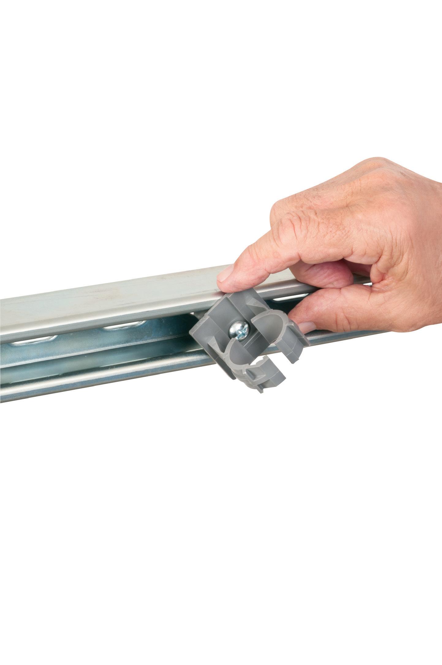
at the
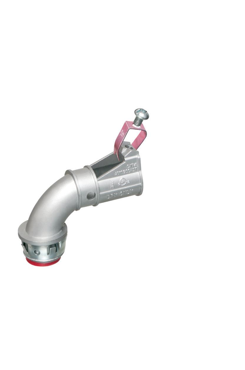
(centerline). Fold the strap over the
and insert the locking tab in the
ELECTRICAL TESTING EDUCATION
EV Infrastructure
This twice-a-month e-newsletter tracks the development, design, installation, and safe operation of electric vehicle supply equipment and systems.
Topics covered include:
• Applying NEC requirements
• Industry news and trends
• New products
• Federal investment allocation
• National EV charging infrastructure buildout development
Subscribe Today
See all of our EC&M e-newsletters at www.ecmweb.com
CONCLUSION
For more than 26 years, I have been an advocate for facilities of all types to perform maintenance of their electrical systems. Over those years, I have been amazed by the number of facilities that wouldn’t perform maintenance. The reasons are varied. “Our system is too small;” “We are lightly loaded;” or “Our production schedule or budget won’t allow for maintenance.”
In our own lives, we recognize the benefits of maintenance. Change the oil in your car. Fix that small water leak on the toilet water supply hose. It’s the adage of pay me now or pay me later. In my experience, it was rare to get a call about a failure from facilities that did some form of regular maintenance — acts of nature were the unavoidable exception.
As I reflect on all those years of maintenance activities, I wonder how many tens of millions of dollars we saved our clients by providing electrical preventive maintenance and preventing unplanned downtime. More important to me — and more difficult to quantify — is how much safer the working environment has been for those who interact with power system equipment. Engage your clients, and be the advocate for change and continuous improvement of their electrical maintenance program. Remember, more than 80% of a good electrical maintenance program is taking care of the daily simple things.
Mose Ramieh III is vice president, business development at CBS Field Services.
Photo 5. Partial discharge evidence can be seen on this WLI-style switch.
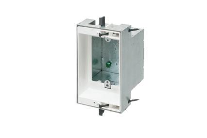
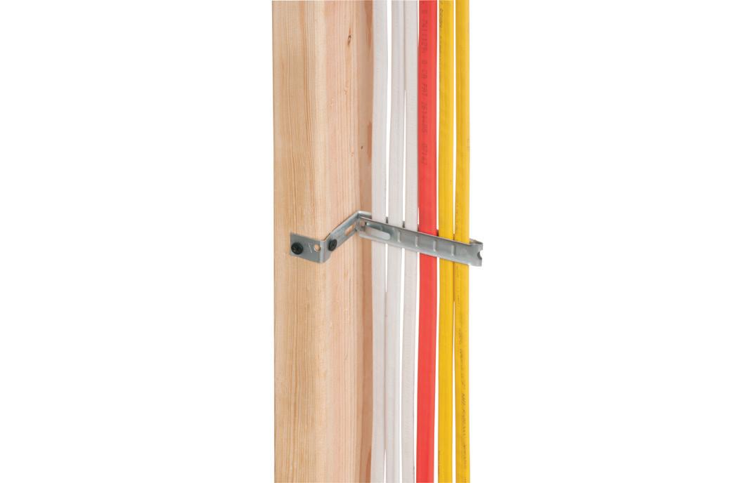
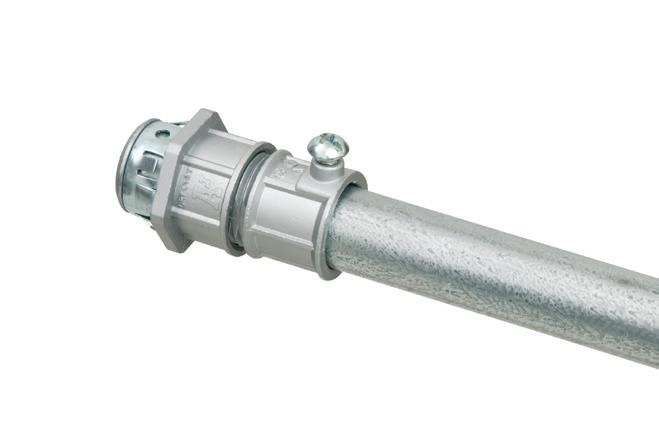
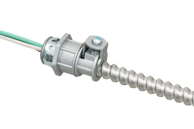
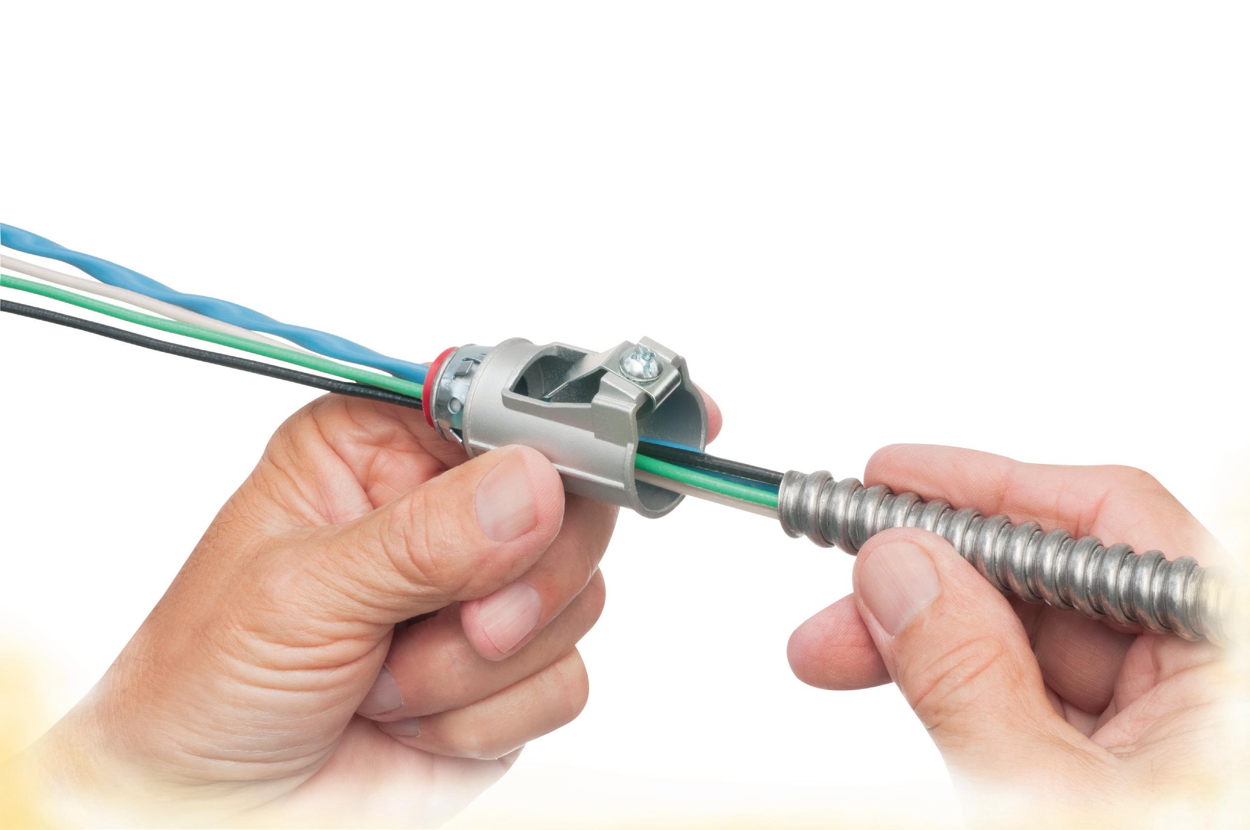
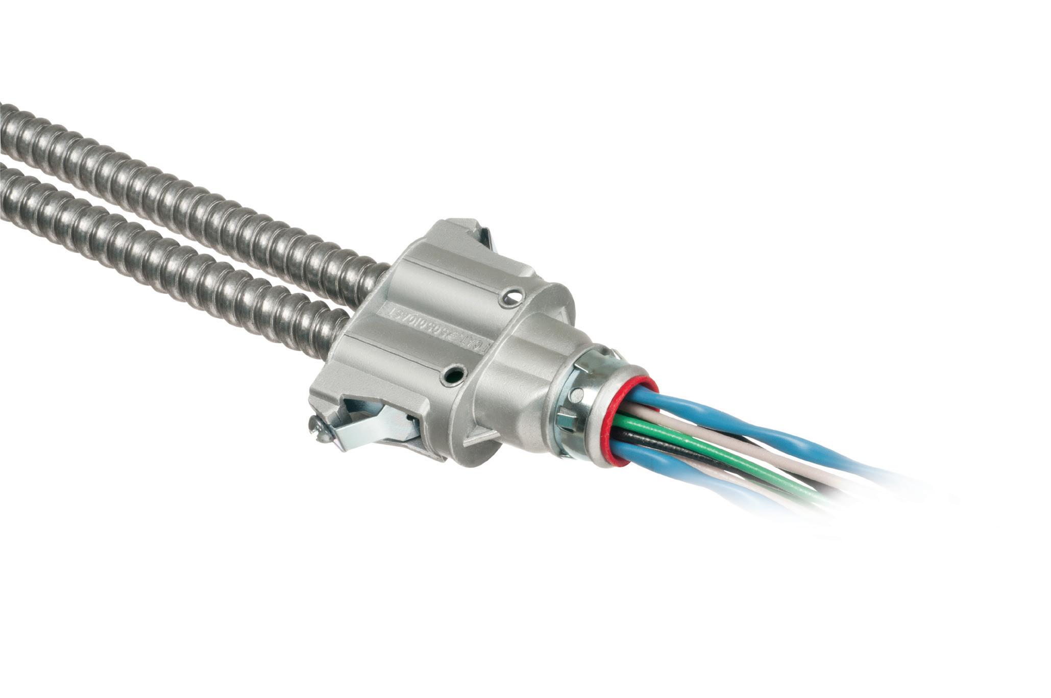
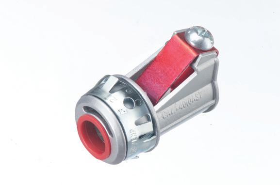
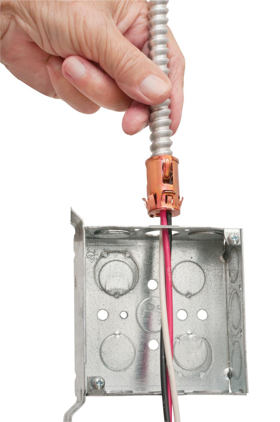
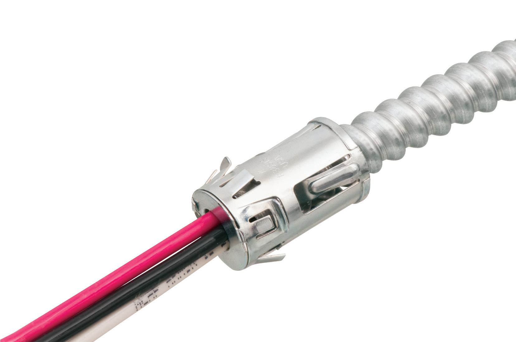
Arlington’s new one-piece RETROFIT SNAP2IT® fittings are easy to use in an OLD WORK installation, and handle the widest variety of cables! They’re ideal for adding additional circuits to a load center. And you get the same labor-savings in a retrofit installation!
Easy snap-in installation - NO TOOLS. Install connector into the knockout in an existing box, pulling cable/conduit through the knockout. Slip the fitting onto the cable, then snap the assembly into the box. That’s it... a secure installation with no pullout
Widest total cable ranges 14/2 to 10/3
Widest variety of cables AC, MC, HCF, MC continuous corrugated aluminum cable, MCI-A cables (steel and aluminum), AC90,
•
•
•
& CONTROL
The Lagging Transition to LEDs in Schools — Part 3
Understanding the main types of fluorescent replacement lamps and how those choices compare to one another
By Jessica Kelly and Andrea Wilkerson, Pacific Northwest National Laboratory, and Dan Blitzer, The Practical Lighting Workshop
Parts 1 and 2 of this series discussed the sluggish adoption of LED technology in schools and the dim prospects for fluorescent lighting. This final part addresses the LED choices school facility personnel are considering and the new tradeoffs they face.
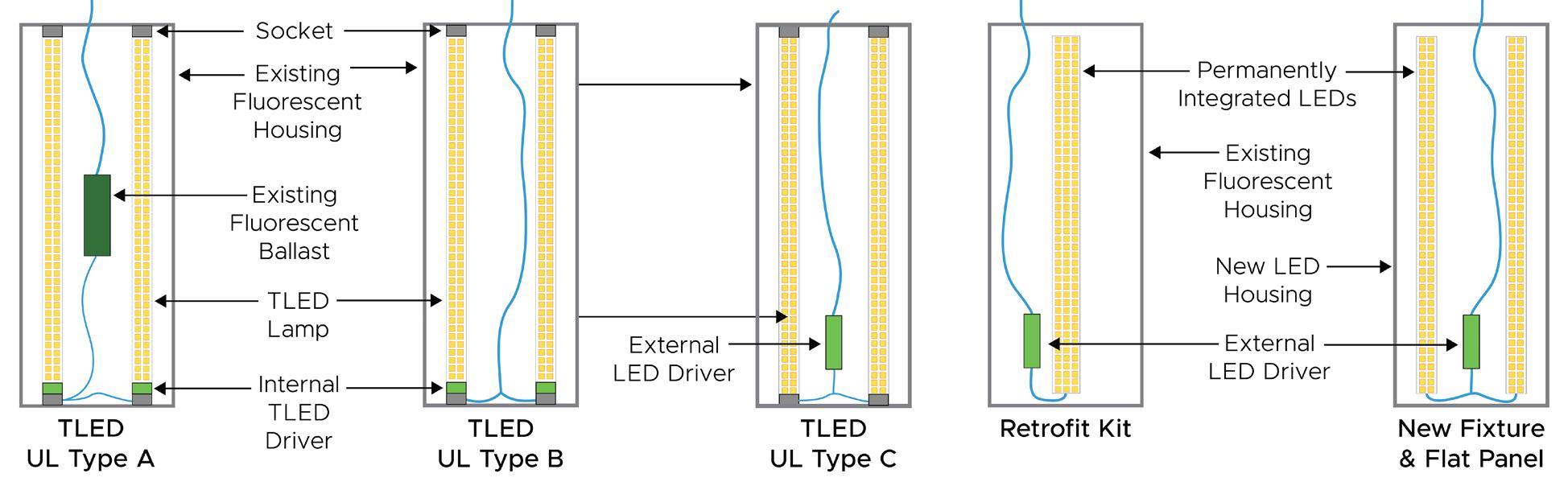
Three primary LED replacement options are available for linear fluorescent installations: replacement lamps, retrofit kits, and new LED luminaires (see Figure above). Replacement fluorescent lamps are often referred to as tubular LED or “TLED” lamps, and Underwriters Laboratories (UL) has defined three types of TLEDs — Type A, Type B, and Type C. Others might refer to them as, respectively, “plug and play,” “ballast bypass,” and “external driver.”
LED retrofit kits are installed into the fluorescent luminaire housing and replace the existing electrical and optical components. New LED luminaires
are used to replace the entire existing fixture, including the housing.
New luminaires and Type B TLEDs were the most common LED options installed at the 30 schools PNNL visited over the past year. Maintenance staff favor TLEDs due to their simplicity, despite safety concerns and issues around lighting quality. On the other hand, schools appreciate new luminaires’ updated look and efficiency, even as some have struggled to maintain them without replaceable components. In addition to output and color decisions, schools need to balance cost, quality, and future maintenance when assessing their upgrade options. So, how do the choices compare?
LIGHTING QUALITY
Three aspects of lighting quality merit attention from schools considering upgrades from fluorescent lighting: light output, color, and flicker. Well-designed and constructed TLEDs, kits, and luminaires can provide both the quantity and
color of lighting appropriate for schools. With quality products available in all LED upgrade types, a suggested best practice is to visually evaluate one or several LED solutions. Comparison can be an effective way to evaluate options and identify unpleasant surprises before committing to a large-scale upgrade.
School decisionmakers also need to evaluate flicker performance. Type B TLEDs are raising concerns about flicker, which can pose health and behavioral risks for school populations. In one school that PNNL recently visited, a few teachers reported that they turned the lights off as much as possible due to discomfort, although the specific cause was not identified.
Due to reports from installers and initial lighting quality measurements in the field, PNNL tested 28 Type B TLED lamps in a laboratory setting with discouraging results: 22 of the products flickered at rates worse than old fluorescent lamps operating on
LED options for replacing linear fluorescent lamps include TLED replacement lamps, retrofit kits, and new luminaires.
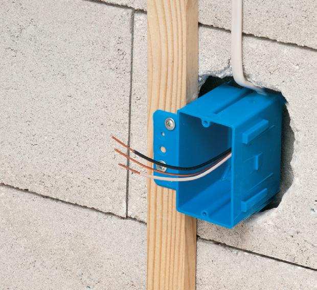
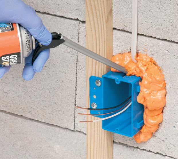
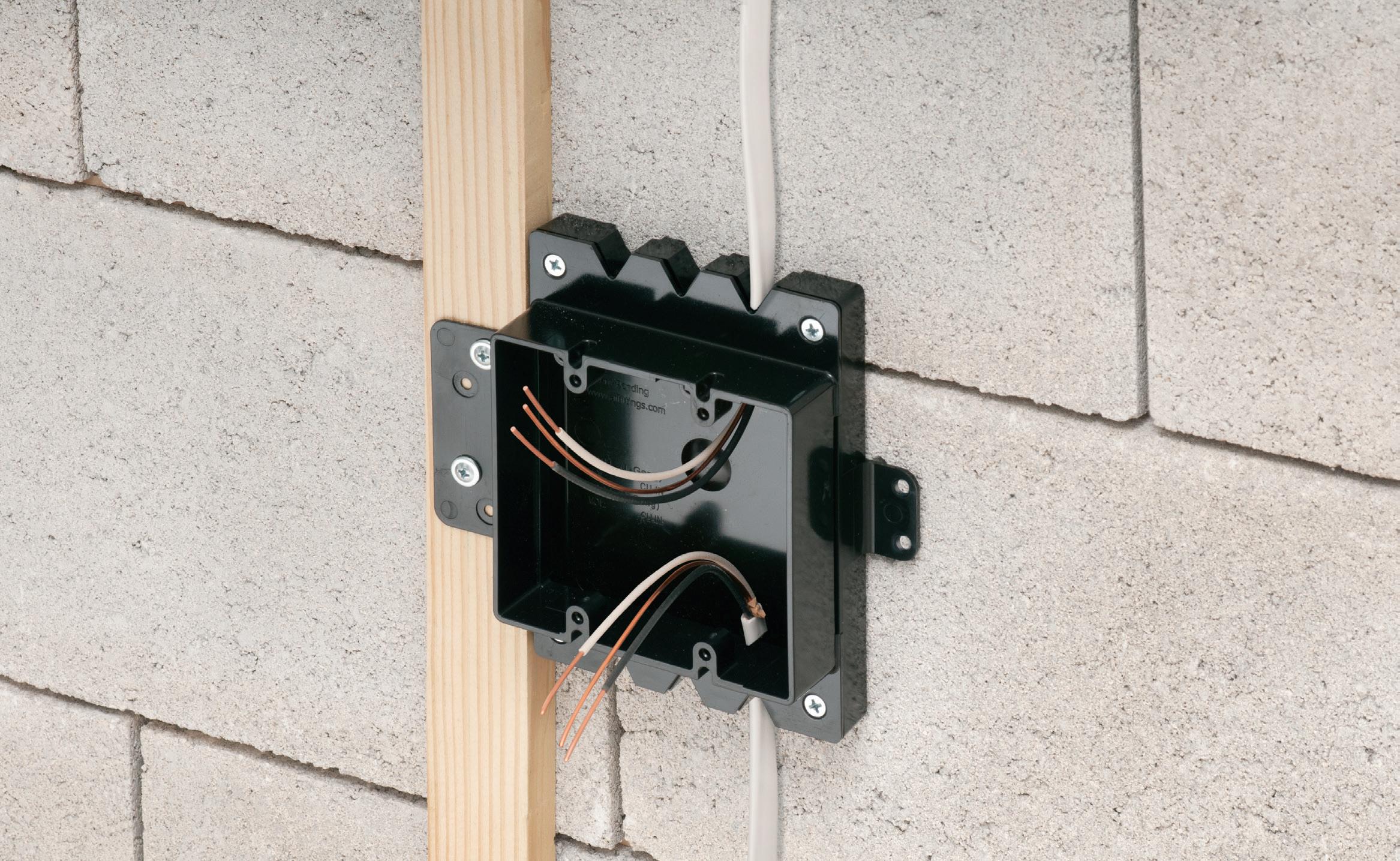
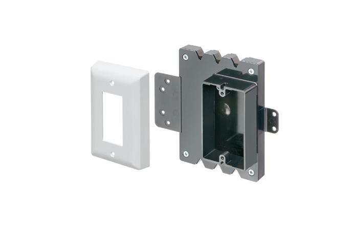
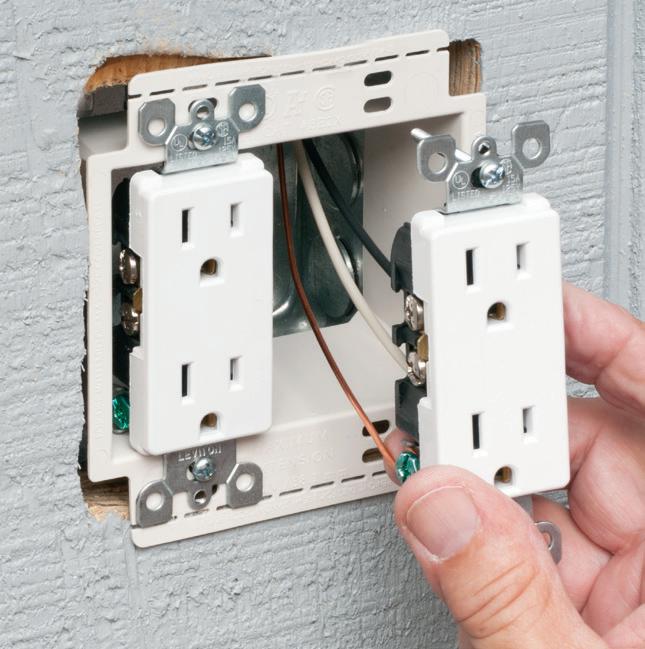
Arlington’s new Furred Wall Box™ kit makes challenging outlet box installations fast and easy!
Versatile mounting options Our high strength FSB series outlet box kits are designed for use with existing 1x2 drywall furring strips – but can also be mounted directly to a concrete block wall between furring strips – so installers can place the box or outlet where it’s needed.
No cable pullout! Accommodates GFCI and USB receptacles. Convenient kits simplify ordering.
Large, pancake-style box with cover
High-strength No breakage in cold weather
Integral Mounting Flanges
FSB2
LIGHTING & CONTROL
Fluorescent
Type A and C TLEDs
Type B TLED
Retrofit kits and new luminaires Varies by product
Fluorescent ballast Maintenance staff
Fluorescent lamps Cleaning staff
Fluorescent ballast (Type A) Maintenance staff
LED driver (Type C) Electrician
TLED lamps (Type A or C) Maintenance staff
TLED lamps (integral driver) Maintenance staff or electrician
LED drivers may be replaceable; most other components are difficult or impossible to service. Typically, upgrades will be repeated at the end of life.
Electrician
Who takes care of new LED lighting equipment after its initial installation? The task and type of equipment drive this decision.
magnetic ballasts. Literature on 11 of the products claimed low or no flicker, but these Type B lamps varied in measured performance, which highlights how challenging it can be to select highquality products. Generally, other LED options measured by PNNL in schools did not exhibit flicker at levels similar to Type B TLEDs. Watch the “Flicker Demonstration” video at https://www. energy.gov/eere/ssl/flicker-demonstration for a short explanation of how to identify flicker.
THE ECONOMICS
TLEDs offer the lowest cost in terms of initial materials. LED retrofit kits usually cost more, and new LED luminaires typically have the highest cost, although these upgrade categories vary greatly with some very affordable options available. Installation costs are generally the lowest for Type A TLEDs, as these simply install in the existing fixture without rewiring. Type B and C TLEDs require some rewiring that may result in labor costs comparable to retrofit kits or new luminaires.
In terms of operating cost, new luminaires are likely the most efficient option as they are optimized for the size, thermal performance, and directional light output of LEDs. Compared to fluorescent, new LED luminaires can reduce the connected lighting load by up to 60%, while TLEDs operating on fluorescent ballasts can expect to reduce the lighting load by about 20%.
Schools should consider how lighting controls could increase savings and
introduce flexibility into classrooms. Facility personnel often noted that teachers appreciated the ability to adjust light levels. New luminaires, retrofit kits, and Type C TLEDs are the most compatible with advanced controls; however, some Type B TLEDs now offer networking capabilities and other control features.
ONGOING MAINTENANCE
Lighting maintenance is an important consideration when upgrading from familiar fluorescent lighting. Fluorescents can be replaced and maintained by cleaning staff, and standardized replacement lamps, ballasts, and sockets are readily available, at least for now. LED options check some (but not all) of these boxes.
Who takes care of new LED lighting after initial installation? What needs to be replaced? Are replacements available, and are they compatible? The maintenance of different LED options varies, as shown in the accompanying Table.
Type B TLEDs feature an integral driver in the tube, which simplifies maintenance to one component and eliminates compatibility challenges. Compatibility between components used with Type A or Type C TLEDs has yet to be standardized. Type C TLEDs generally operate with drivers from the same manufacturer, while Type A TLEDs lack the broad compatibility of the fluorescent lamps they replace and can perform poorly when operated with some fluorescent ballasts. What happens when a compatible ballast is no longer available? Products with compatibility
challenges may not be the best solutions for schools, especially when completing an upgrade over time.
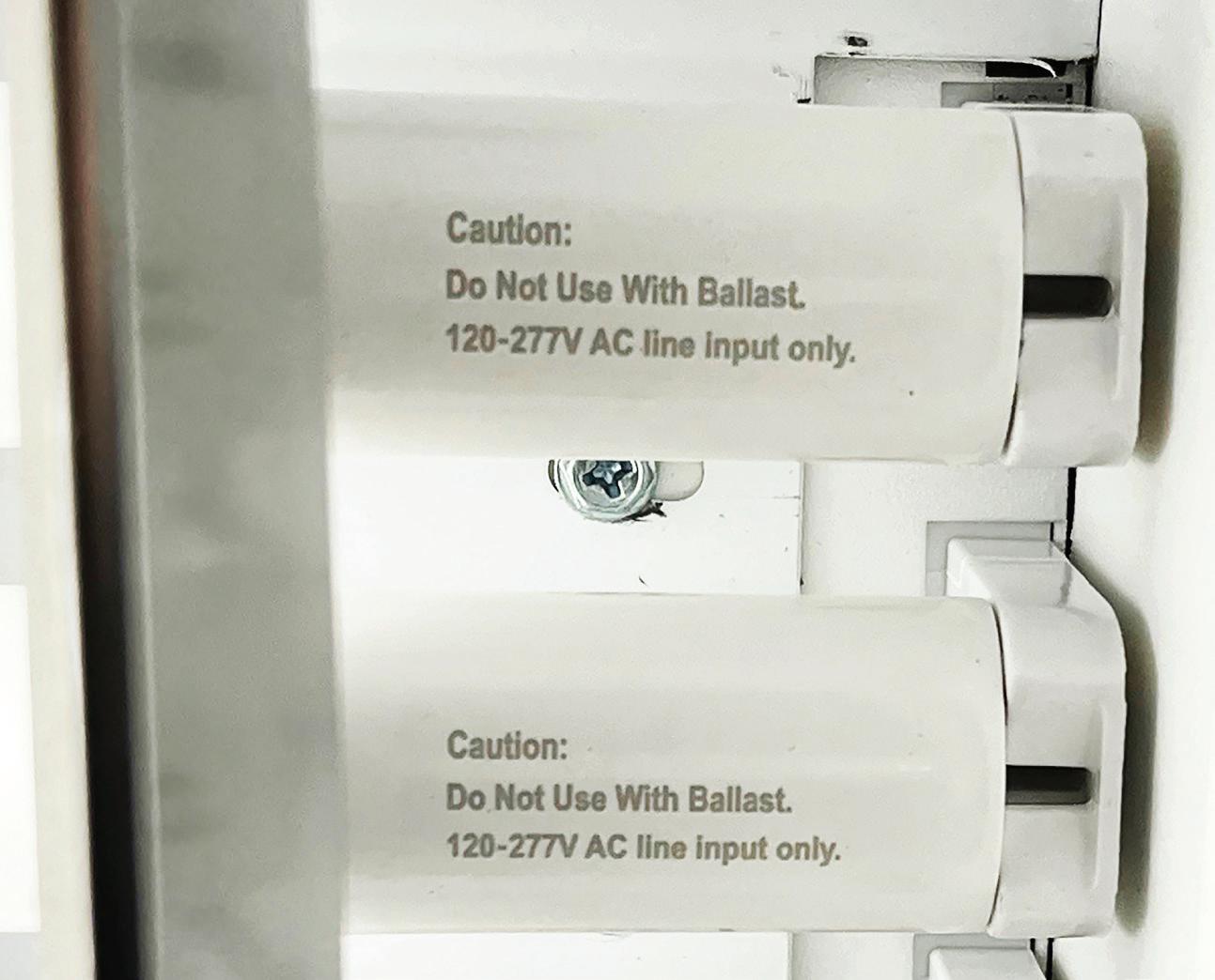
Type B TLEDs may appear to be the easiest solution to maintain. Nevertheless, many Type Bs on the market currently are prone to flicker and may pose safety hazards if improperly rewired or relamped. During the installation of Type B TLEDs, existing ballasts are removed, and line voltage is connected directly to the lamp holders — either to one end or both. A single-ended TLED saves wiring time but poses a shock risk if the luminaire is not de-energized and a person touches the exposed end of a partially installed lamp. Double-ended TLEDs reduce the risk of shock because the ends of the lamp are not energized until they both are fitted in the socket.
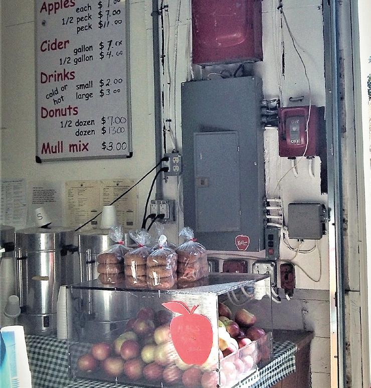
In addition, accidentally installing a fluorescent or a Type A TLED can create a fire hazard due to the lack of an appropriate power supply. Labeling of modified luminaires is required, but the wording, size, and placement of these labels vary. Examples of variable product labeling are shown in the Photo on page 24. During interviews, some school facility personnel mentioned that only electricians or trained maintenance staff change TLEDs due to these concerns. Increasing awareness of the risks as well as separating stock and limiting to one wiring configuration moving forward can greatly reduce the risks.
Retrofit kits, flat panels, and new LED luminaires may not be serviceable, so the entire product will need to be replaced at the end of life. Even where
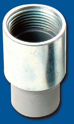
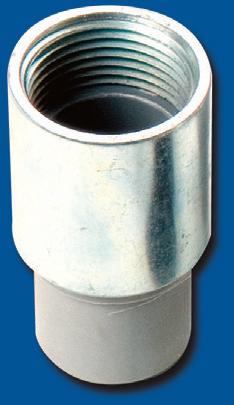
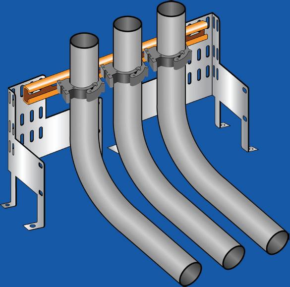
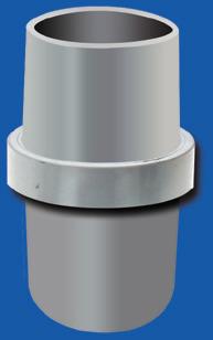
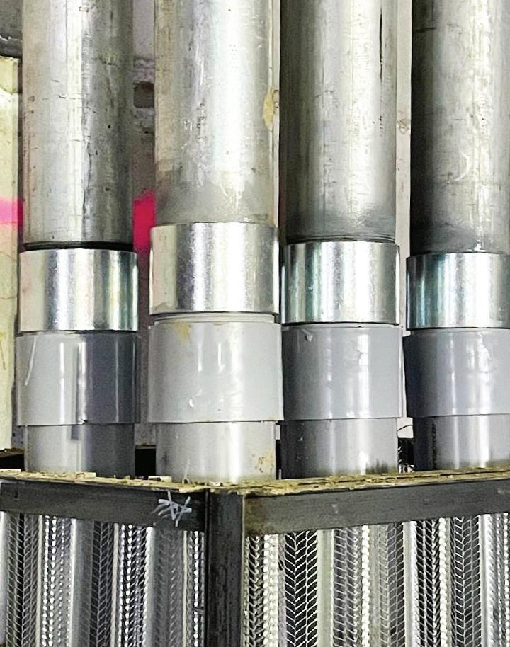
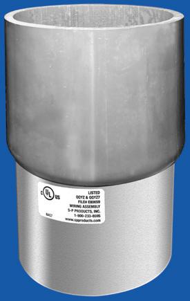
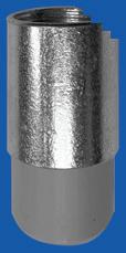
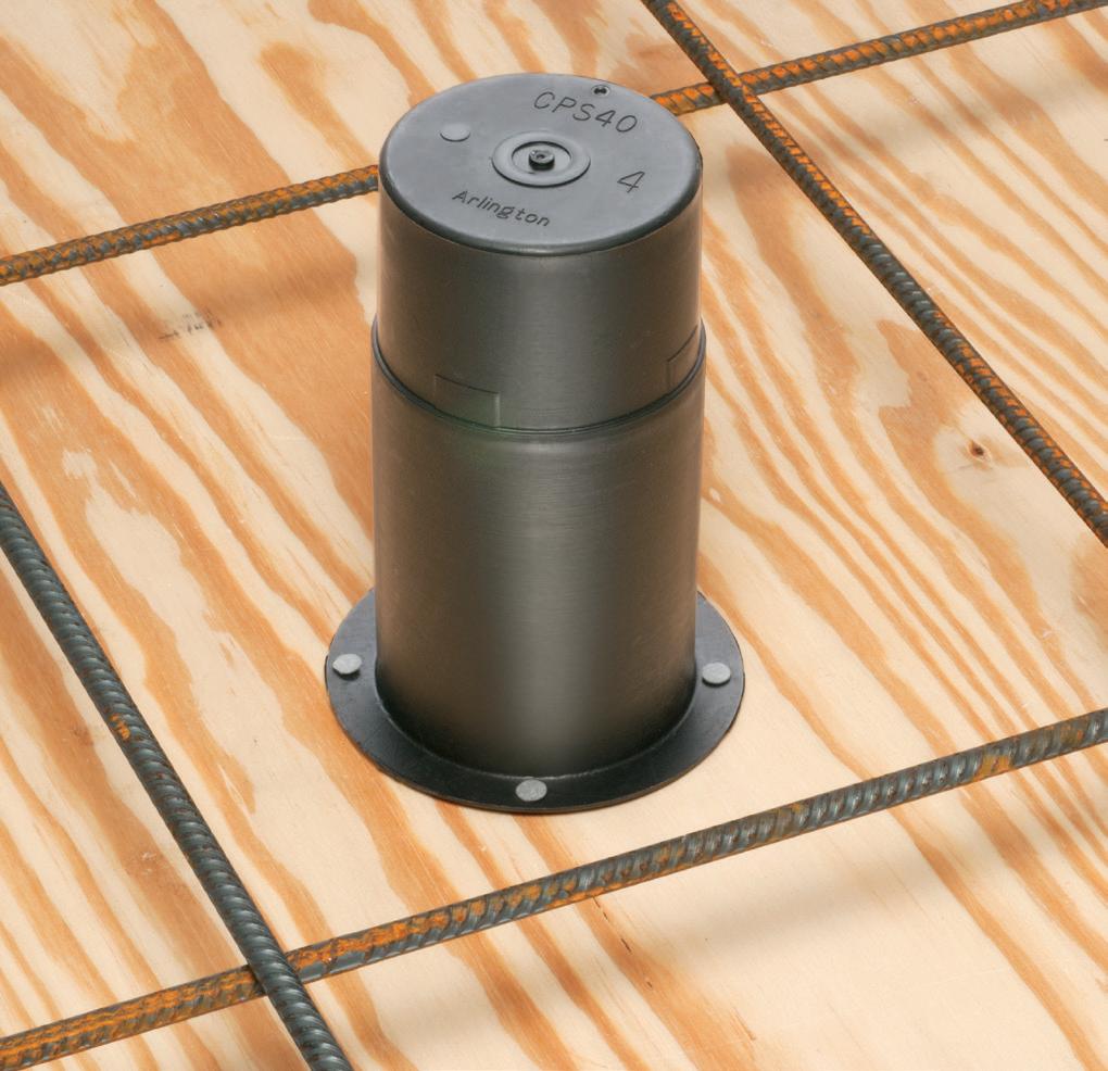
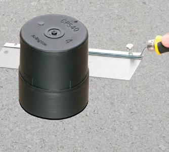
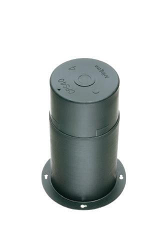
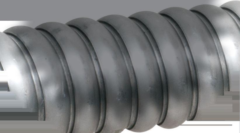
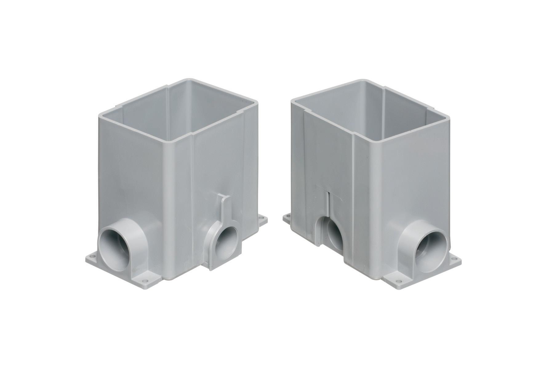
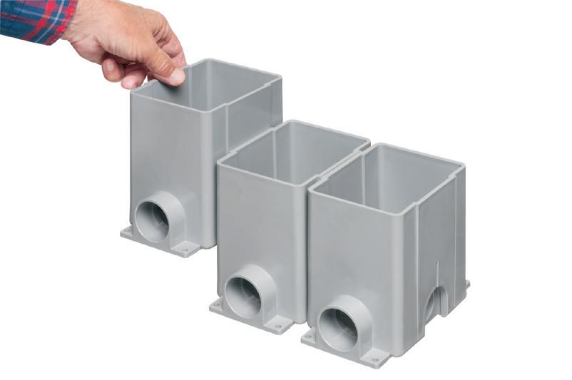
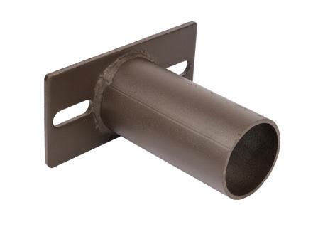
CONCRETE PIPE SLEEVE
POURS!
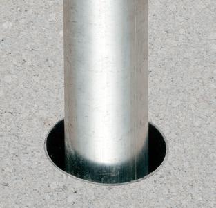
Arlington’s Concrete Pipe Sleeves are the economical way to sleeve through concrete pours in tilt-up construction WALLS – and FLOORS allowing cable and conduit to run easily from one floor to the next.
No costly core drilling – No cutting holes in the form. Plus, you can position the hole prior to pouring the concrete.
• Attaches to form with nails or screws
• Stackable up to 23" h for extra deep pours
• Vents keep wet pipe sleeves from sticking together
• Multiple hole sizes: 1-1/2"
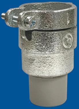
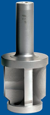
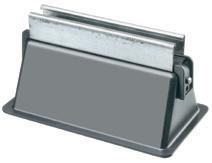
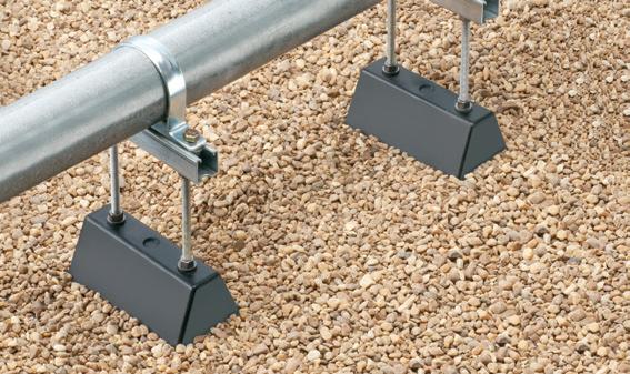
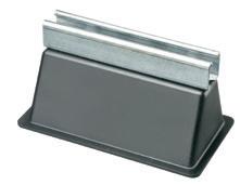
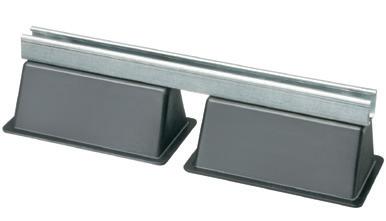
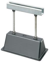
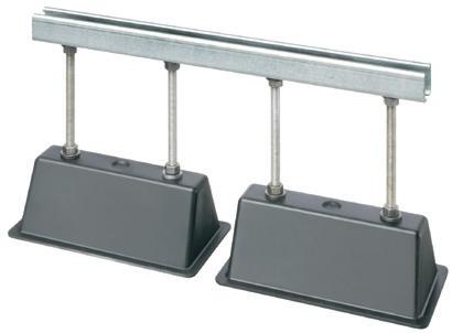
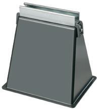
ROOF TOPPER® supports raise conduit/raceway 4" or more off the roof surface, allowing contractors to comply with the 2017 NEC® for temperature adjustment for circular conduit.
The heavy-duty base, made of 100% recycled material, sits on the roof deck. There’s no need to mount ROOF TOPPER to the surface with mechanical fasteners.
Offered in a variety of sizes and configurations, ROOF TOPPER supports up to 2000 lbs, and stands up to extreme rooftop conditions protecting and elevating conduit or raceway above the roof deck.
CPS40
After concrete sets, cut sleeve flush with surface. Insert conduit into sleeve.
Nail sleeve to form.
LIGHTING & CONTROL
Illumination Insider
This e-newsletter tracks the research, development, design, installation and operation of all types of lighting and control products.
This twice-a-month product is geared toward professionals working in the industrial, commercial, retail, residential, institutional, health care, government, and utility market sectors.
Luminaires modified for Type B TLED lamps should not be operated with other wiring configurations or lamp types, including fluorescent or other TLEDs.
drivers are serviceable or replaceable, a compatible option will need to be available. Whether just a driver or the entire luminaire needs replacement, an electrician will have to do the job. Half of the schools PNNL interviewed did not have an electrician on staff, and many struggled to hire electrical contractors. Talk of “right-to-repair” and replaceable LED components is heating up, but widely standardized LED lighting systems similar to fluorescent will not be available for some time.
LOOKING AHEAD
Subscribe Today
See all of our EC&M e-newsletters at www.ecmweb.com
Based on PNNL’s conversations with schools, the change to LEDs is underway. Upgrading lighting can reduce energy consumption and operating costs and refresh the look and feel of the school. So what can schools do to prepare for an upcoming conversion?
Evaluate options in pilot classrooms. Evaluate everything from the installation process itself to the lighting performance. Good quality lighting should provide a comfortable amount and color of light for tasks without producing glare and should adequately light people’s faces to support communication. Poor lighting with glare or flicker
can lead to headaches, eye strain, and other negative effects.
Think long-term, and make a plan. Fluorescent lighting has served schools for a long time. What does maintaining an LED system look like for the next 30 or 40 years? While TLEDs seem like an easy solution today, relying on fluorescent luminaires and other components will become more challenging in the future. Compare the up front and ongoing costs for each LED option and consider developing a “standard” lighting solution that can be repeated over time, space by space, or school by school.
Do you have experiences or successes of your own to share? Reach out to our team at jessica.kelly@pnnl.gov.
Jessica Kelly is a lighting research engineer at Pacific Northwest National Laboratory.
Andrea Wilkerson is a lighting research engineer at Pacific Northwest National Laboratory. She can be reached at andrea. wilkerson@pnnl.gov
Dan Blitzer is principal of The Practical Lighting Workshop, a consultancy in marketing and education for the lighting industry.
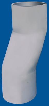
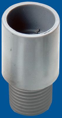
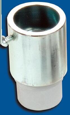
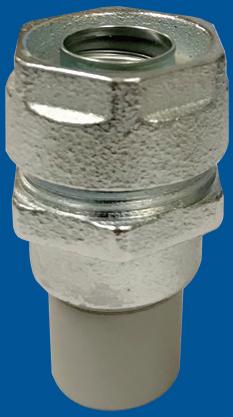
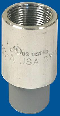
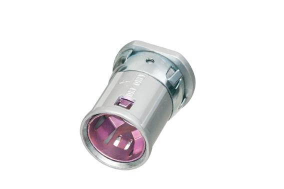
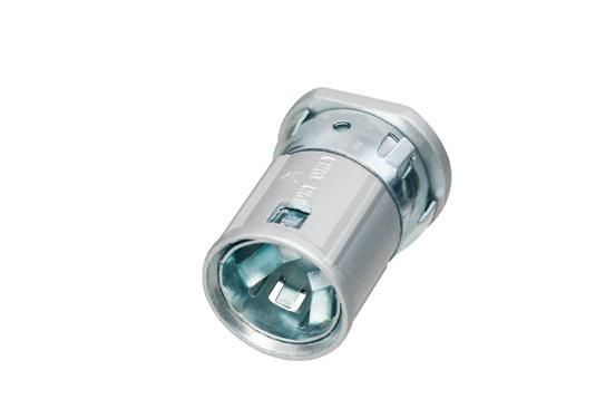
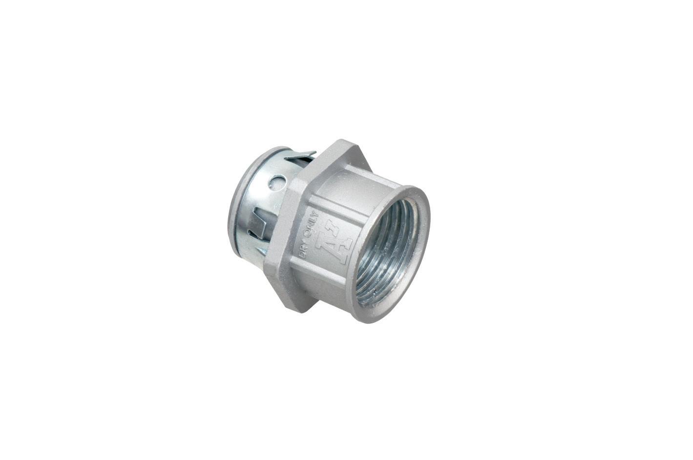
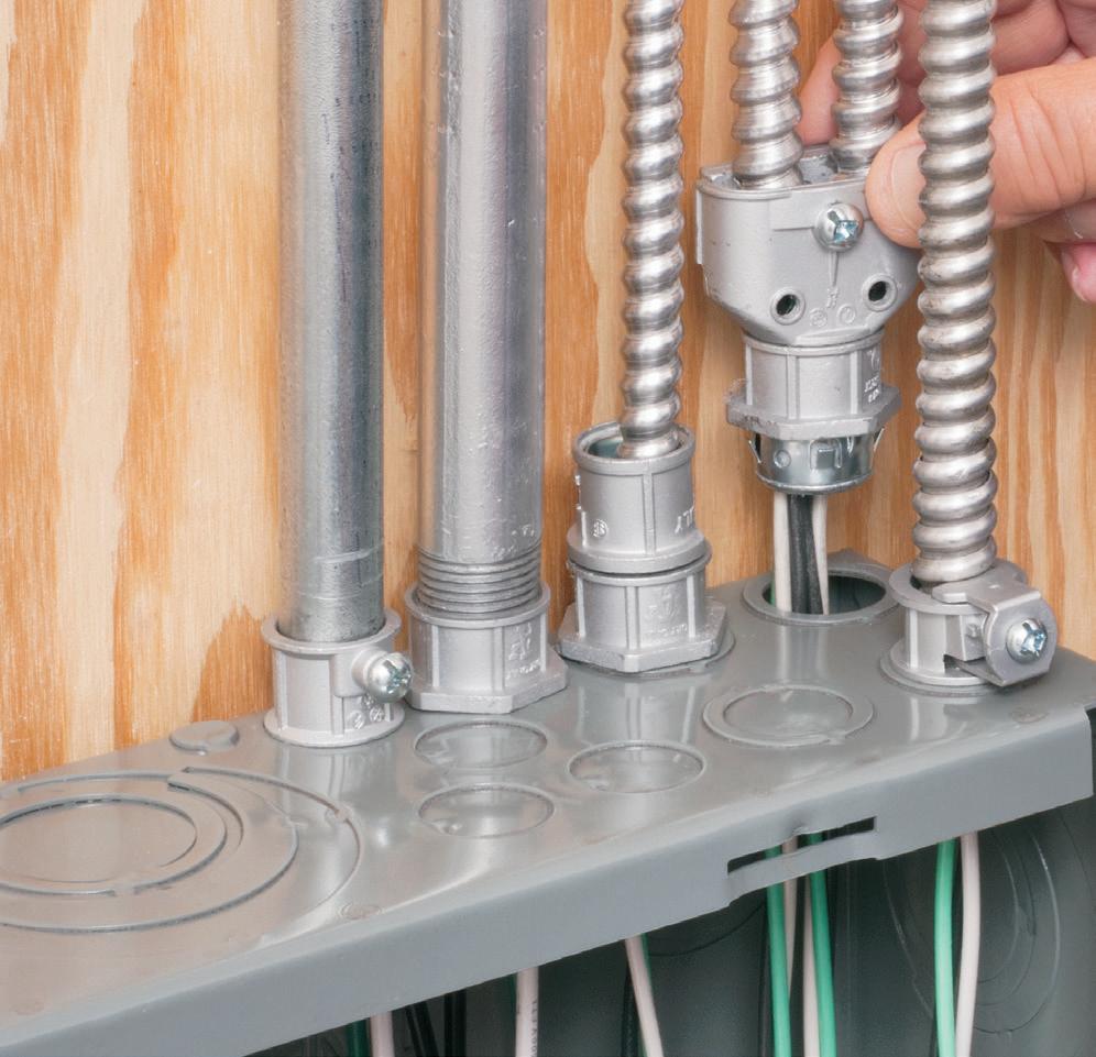
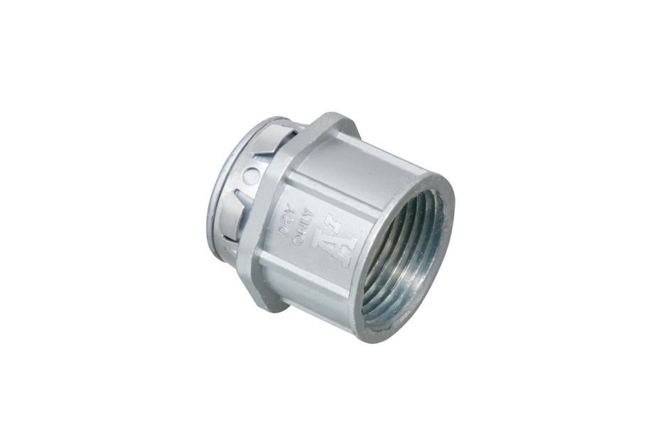
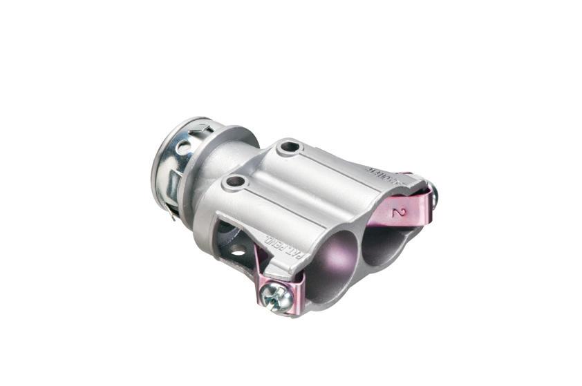
In a tight spot? Arlington’s new SNAP-TITE® Transition Fittings offer the time-saving solution for installing additional conduit or cable in an already congested panel. They allow installers to work around tightly spaced, installed fittings in a panel, box or enclosure – where installing and tightening additional locknut fittings would be
Convenient, Time-Saving snaps into a 1/2" knockout and connects 1/2" trade size threaded fittings or pipe.
aifittings.com/landing/2450st
to
• 2-Hour Fire Rating
• Low voltage side has a combo 1/2" and 3/4" KO for raceway
• Includes NM cable connector (power side)
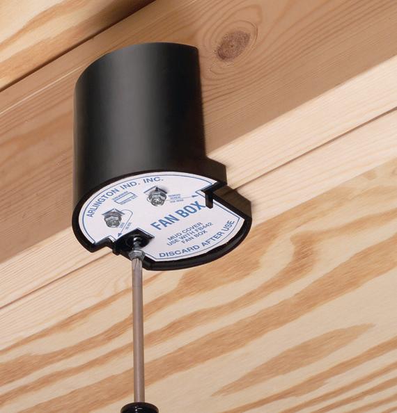
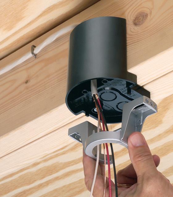
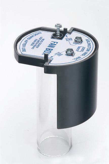
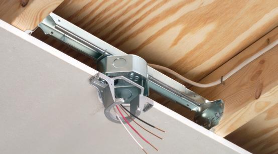
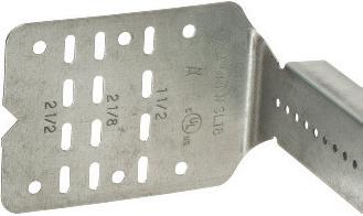
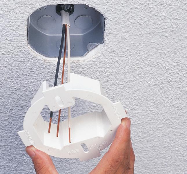
Super-secure installation! Our lowest cost, L-shaped fan/fixture box mounts to single or double joists with a captive center screw. No loose parts! screws ship captive, ready to install box and bracket.
For 1/2" or 5/8" drywall Fast, easy installation
• Locator posts assure proper positioning of fan/fixture bracket
• 2-hour Fire Rating
Why PV Inverter Failures May Lead to AC Power Quality Issues
Case study examines a common PV inverter failure that can drive uncommon issues in the field — namely, damage to the AC protection equipment from DC fault currents for short periods during transformer-less inverter power electronic failures.
By William Sekulic, Electrical Engineer, PE, and Greg Linder, Electrical Engineer, PE
Even though inverters have been steadily improving in reliability, they are still the most common point of failure in a photovoltaic (PV) system. Inverter failures could be related to infant mortality, installer error, or age and wear. Roughly 34% of inverters fail within the first 15 years of installation, according to a 2022 paper by Christof Bucher, Jasmin Wandel, and David Joss titled “Life Expectancy of PV Inverters and Optimizers in Residential PV Systems.” But what happens when they do fail — is it a simple swap out and replace? Or can there be other unforeseen issues?
Changing damaged devices is straightforward and shouldn’t require significant troubleshooting. But the product overview and case studies presented in this article show that, even today, there is still room for improvement in current designs — and lessons from the past should be rolled into all future designs. This piece will demonstrate how failures in grid-tied inverters can lead to more costly repairs.
CURRENT INVERTER DESIGNS
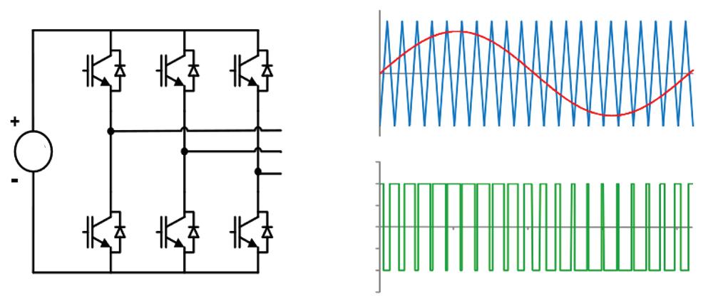
Due to the pressure for smaller and more cost-effective machines, most string and micro inverters are transformer-less
inverters or those that contain no galvanic isolating devices to separate the DC and AC conversion components. These inverters contain a network of switches that are turned on and off at specific intervals to create a pseudo sine wave, as explained in “Harmonics and Noise in Photovoltaic (PV) Inverter and the Mitigation Strategies” at www.solectria.com. Failures in this switching network can have a catastrophic impact on the inverter circuits as well as the DC components upstream and the AC components downstream. Manufacturers include failsafe and/or bypass blocking switches to provide an electronic
Fig. 1. Transformer-less inverter sine wave generation.
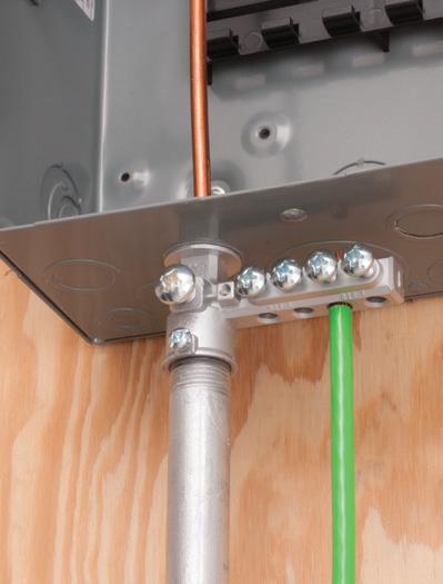
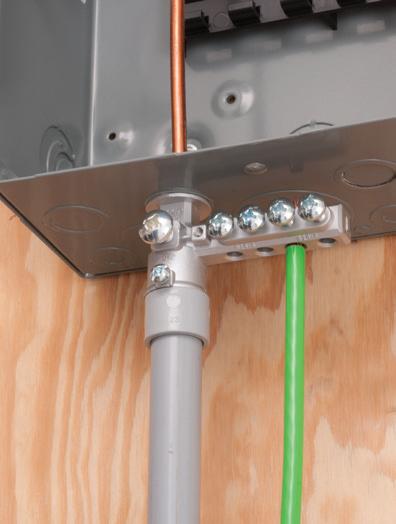
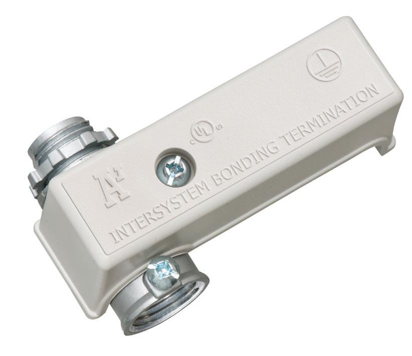
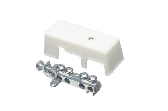
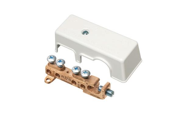
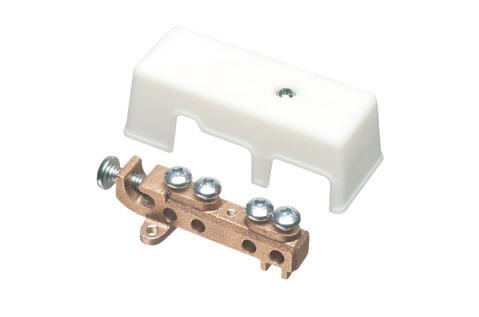
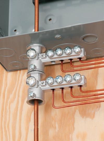
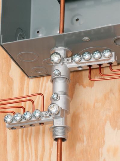
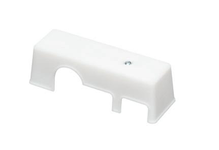
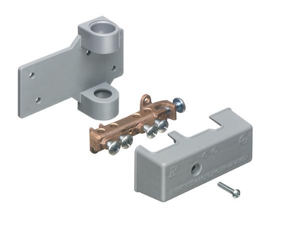
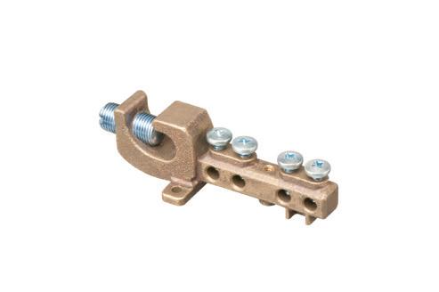
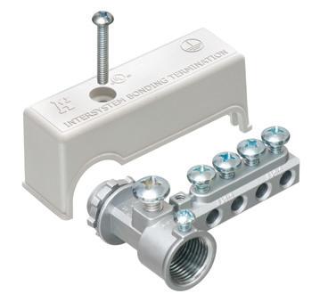
GROUNDING BRIDGE
MULTIPLE ZINC
Arlington’s heavy-duty Grounding Bridges provide reliable intersystem bonding between power and communication grounding systems. And handle multiple hookups of communications systems: telephone, CATV and satellite.
Our new GB5T is THREADED for threaded conduit or another GB5T – with a SET SCREW for use on EMT or PVC.
Arlington’s zinc and bronze grounding bridges...
• Four termination points; more than required by the NEC
equivalent of the galvanic isolation found in transformer-based inverters. This switch network, when designed properly, separates the AC and DC currents during operation and in the event of a failure. The DC circuit elements (PV modules) should never directly interact with the downstream AC panelboards and breakers (Fig. 1 on page 26).
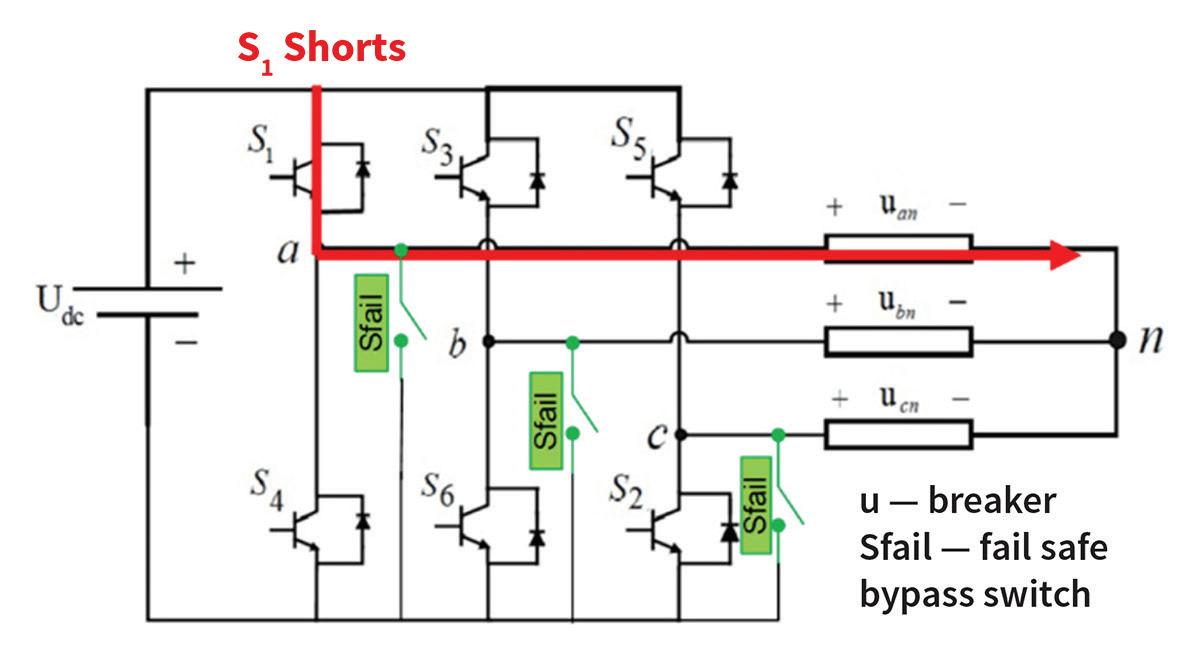
How do these switches work? In the event of a switch network failure, the inverter will shut down and either block or short the DC current to ground or common. In Fig. 2, these switches are labeled “Sfail.” In this topology, the switches would be turned on, and the DC current would be shorted back to the PV modules during the inverter shutdown. Proper design would dictate that, in the event of a switch network failure, other elements in the circuit are protected, and damage to infrastructure or other adjacent equipment is minimized.
But what happens if the designs are less than optimal or are missing the necessary failsafe switching? Inverter failures can be catastrophic to the internals of the machine, releasing significant energy into a confined space. Once struck, a DC arc won’t extinguish until the voltage required to maintain the arc is exceeded, as noted in the 2024 IEEE paper, “Modeling the Dynamic Behavior of DC Arcs,” by L.B. Gordon. In an event where the inverter failsafes are absent, improperly designed, or overloaded, it may be possible for DC current to contact the AC bus for a short period of time while that arc is still in process. This would be a worst-case situation and is a condition that the AC panelboard and breaker manufacturers do not design for.
LESSONS LEARNED FROM CASE STUDIES
The cases outlined here reveal that several inverter manufacturers have either improper or inadequate failsafe switch networks that directly contribute to power quality (PQ) issues in several AC panelboards. To better understand these issues, a closer look at how the failures were found, propagated, and ultimately resolved is in order.
Upon commissioning a PV array or system, several electrical and mechanical checks are performed to verify the safety
and installation of said system(s). If a component fails, it is usually promptly replaced after troubleshooting of the existing hardware to ensure that other components were undamaged by the failure. In this case study, failed inverters caused hard-to-detect damage to the molded-case circuit breakers in the switchgear that went undetected by the technicians performing the repairs.
To understand the subsequent failure mechanisms, we provide an outline of the fault and progression here. An inverter fault occurs — specifically, a transformerless model’s switch network fails or burns up. This trips the inverter’s AC breaker, and the repair personnel sent to respond see that the inverter doesn’t power up. The associated AC breaker may exhibit visible charring, smoke, or damage.
However, breaker damage is not always obvious to repair personnel. They swap the inverter with a new unit,
close the breaker, and re-commission the replacement inverter. Upon powerup of the replacement inverter, it will likely turn on and seem to operate normally. In some cases, the AC breaker may smoke, refuse to close, or the new inverter may power up and then immediately shut down due to a PQ fault.
The most confusing case is when the inverter seems healthy, but inverters on adjacent circuits start to show fault codes. It was in this state that we first discovered the underlying problem. One site had a history of inverter faults, including chronic PQ issues and a very high inverter failure rate. At this site, more than 50% of the inverters failed/ required replacement over a four-year period. Subsequently, the AC breakers at this site also needed to be swapped out due to PQ issues, as outlined below.
These PQ issues could extend to all inverters or just a subset connected to the
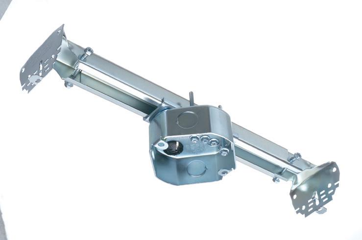
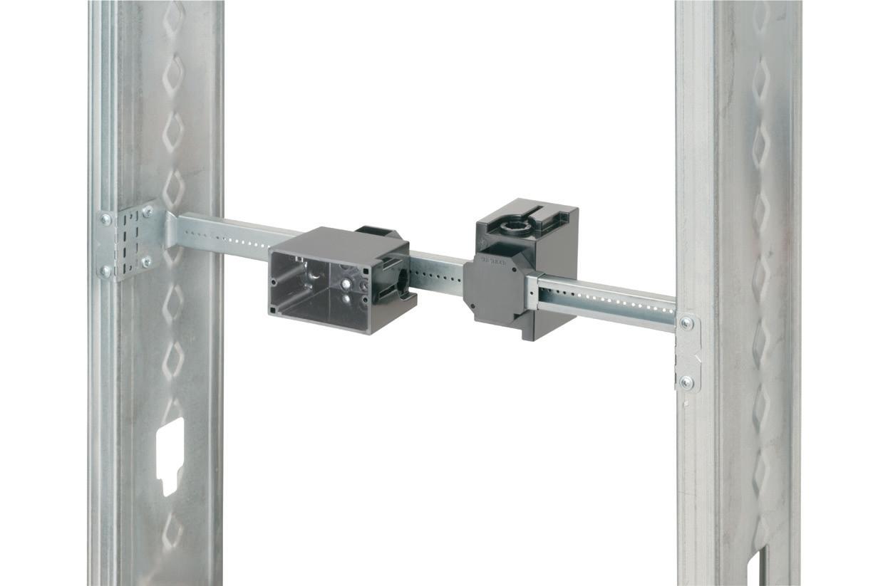
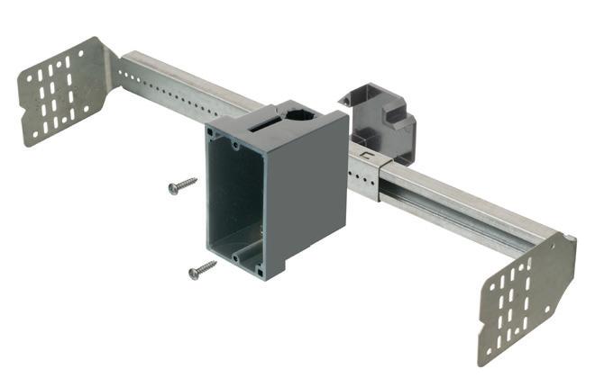
Arlington’s heavy-duty, plated steel fan/ fixture box has an adjustable bracket that mounts securely between joists spaced 16" to 24" o.c.
Flush ceiling installations
FBRS415 is designed for ceilings up to 1-1/4" thick. For 1/2" ceilings, use the pre-bent positioning tab. For other ceiling thicknesses, bend along the appropriate score line.
• 15.6 cu. inch box ships with captive screws, mud cover, installed NM cable connector
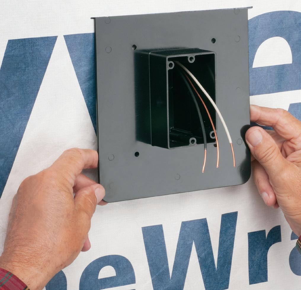
WIDE FLANGED BOXES
Interchangeable backs and extension rings allow ONE box to work with almost any cladding system, including engineered foam and stucco systems.
Extra-wide flanges prevent water and air-intrusion, helping to meet the International Energy Conservation Code, and eliminating the need for gaskets or caulking.
Boxes install before or after the weather barrier house wrap. And ship ready for use with 1-3/8” finish/cladding thickness. Adjustable up to 1-7/8" for CUSTOM depths.
INSIDE PQ
same AC panelboard. As the inverters are allowed to run, the problem tends to get worse. Why? To answer this question, we need to understand a bit about power quality, and, more precisely, distortion.
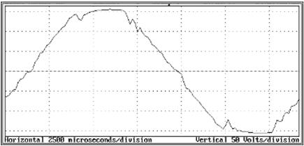
Power quality is the measurement of how perfect the AC current and voltage sine waves are. The measurement is called total harmonic distortion or THD. The amount of distortion is regulated by several standards that describe how the PV inverters interact with the AC grid. These standards — IEEE Std 929-2000 and UL 1741 (the inverter qualification standard) — set the limit to less than 5% distortion. If an inverter measures more than 5% THD, it may shut down and disconnect from the AC bus until either the THD drops below that 5% level or a fatal fault is detected. Figure 3 on page 28 shows an example of a sine wave with 5.7% THD.
Understanding how an inverter reacts to distortion helps determine other potentially damaged components. Increased THD can cause heating in breakers, transformers, and fuses, causing them to prematurely fail. In the case of our study, the increased distortion was caused by an increase in impedance across the inverter’s associated AC breaker. How could breaker contacts create increases in sine distortion?
The shorting of the inverter switching network allowed a DC current to flow from the PV arrays through the switching network where they ultimately contacted the AC breaker. Breakers designed for AC bus and panelboards are not designed for DC currents — even for a short amount of time. Ultimately, the breaker will trip and clear the fault, but it may damage itself in the process. When we examined the system, we found that the breakers had “seen” high DC currents, possibly for extended periods, as the breaker poles arced for the duration of immolation of the inverter switching network. This caused excessive arcing and heating in the breaker switching elements, which resulted in the breaker’s impedance characteristics changing, generally by increasing per-pole impedance.
Breakers designed to interrupt AC currents are designed differently from their DC current cousins, which require special considerations for opening or extinguishing a circuit. Because
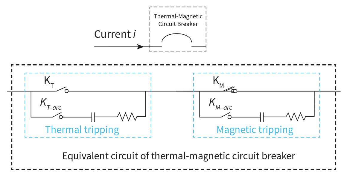
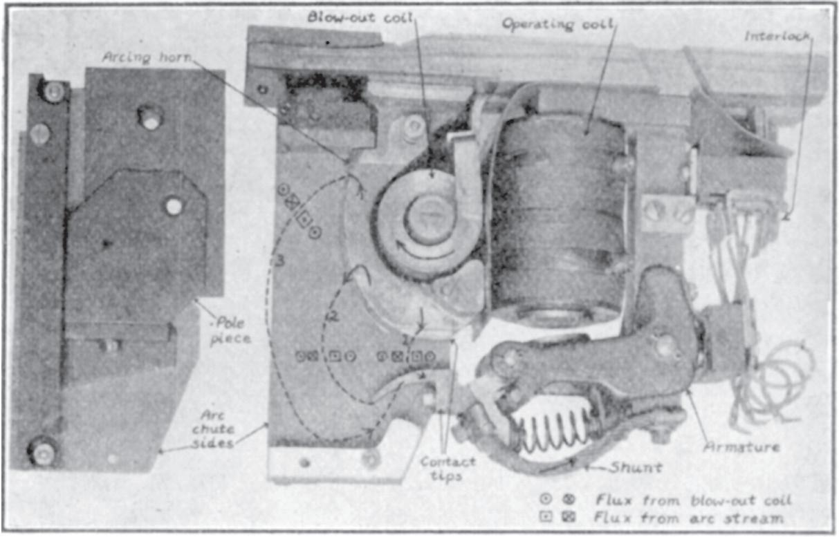
AC power has a zero crossing every 8.33 msec in 60-Hz systems (Fig. 4), as outlined by C. Lei and W. Tian in “Probability-Based Customizable Modeling and Simulation of Protective Devices in Power Distribution Systems,” it allows for simpler mechanical interrupting devices using thermal or thermal-magnetic properties to open an over-current condition. DC arcs, however, need to extinguish,” either via their voltage exceeding that required to maintain the arc or by being extinguished using a “magnetic blowout device” like the one shown in Fig. 5, reprinted with permission from the Journal of the American Institute of Electrical Engineers from the 1922 paper “Air-Break Magnetic Blow-Outs: For Contactors and Circuit Breakers Both A-C and D-C.”
This device is used in parallel with a mechanical trigger to interrupt the cur rent flow and extinguish the arc between poles. Most breakers designed for AC service do not contain such a device, nor is their design sufficient to rapidly burn out a DC arc. This is one reason why breakers rated for both DC and AC service have substantially smaller current ratings when operated under purely DC currents. What happened to the AC breakers in our PV fields? Although the makes, models, and descriptions of the MCCBs in this study have been removed and scrubbed from the data shared here, these breakers are from well-known, prevalent manufacturers. Breakers recovered from the sites exhibiting PQ issues were tested for resistance and impedance. Failed units were visually
Fig. 4. Typical AC breaker electrical circuit diagram.
Fig. 5. Image of a breaker with a DC magnetic blowout coil.
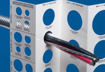
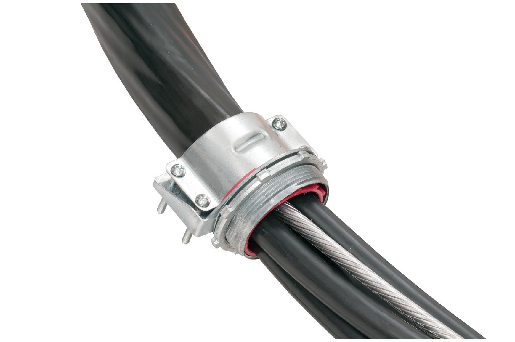
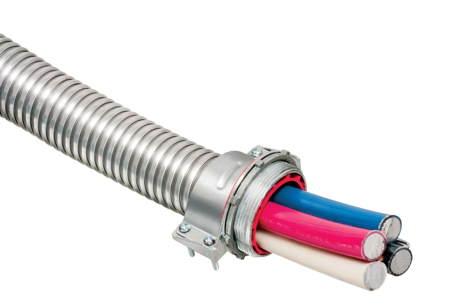
CableStop™ TRANSITION FITTINGS
• TRAY CABLE
• FMC
• MC & PVC MC
• AC90 & ACWU
• TECK Cable
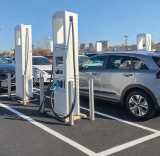
Perfect for data center remote power panel feeds, panels, equipment feeds and EV Chargers in parking garages, Arlington’s Listed CableStop™ Transition Fittings deliver the efficient, cost-effective way to transition feeder cables to 2.5", 3" and 3.5" EMT, IMC and RMC conduit in protective drops, risers and feeds to panels and equipment.
Available with set-screw or compression connections into 2.5", 3" and 3.5" conduit, they ship with multiple end stop bushings that vary the size of the opening – along with a free template select the right bushing for the cable. FROM
Our new CableStop fittings integrate our patented, versatile and SKU-reducing 8412 series cable fittings, with Arlington conduit fittings, allowing for easy transitions to larger knockout sizes.
INSIDE PQ
imaged using X-ray and physically disassembled and inspected for damage. All breakers examined displayed a higher impedance when compared with a factory-fresh device. Each pole was measured to determine whether a pattern could be seen in the limited sample set.
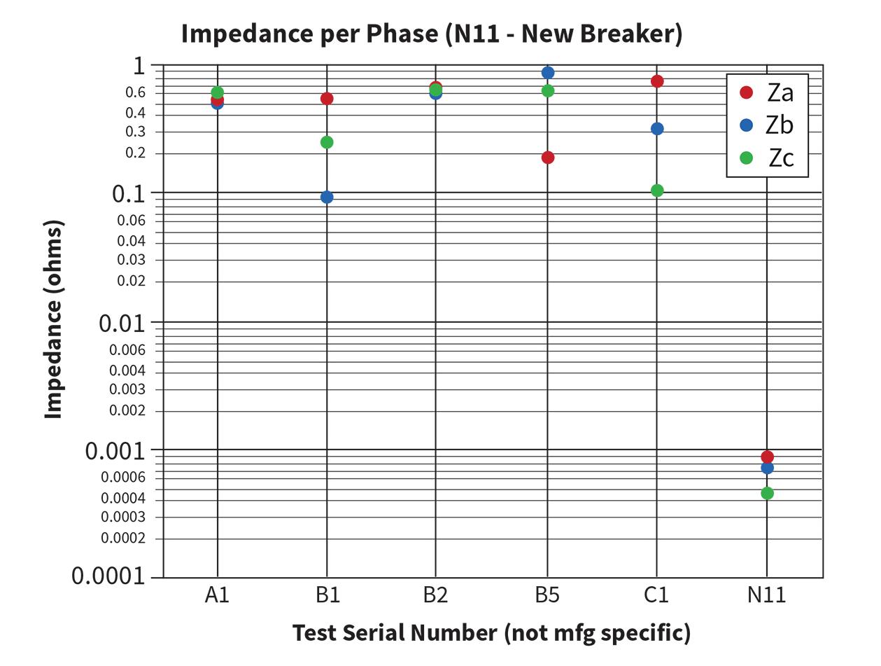
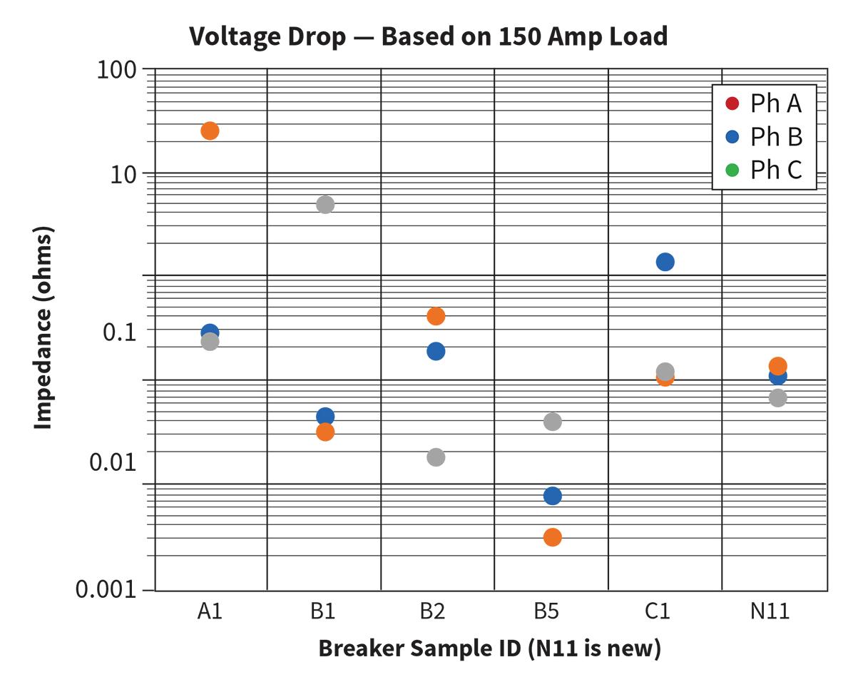
All breakers showed higher per-pole impedance compared to a new, stock device. The impedance across the damaged breaker poles with the breakers closed showed a 10- to 100-time increase in resistance compared to known good breaker poles. Figure 6 shows five damaged breakers (A1, B1-3, and C1) and one known good example (N11). Measurements were taken using a stock inductance, capacitive, and resistance (LCR) meter set up for 60-Hz frequency response. Resistance values were validated using a standard milli-ohmmeter.
The new/good breaker showed less than 1 milliohm of impedance per pole, whereas faulty poles measured between 0.01 and 1 ohm (100 to 1,000 milliohms), as shown in Fig. 6. Additionally, the resistances were not all the same within the same breaker, with B1, B5, and C1 showing per-pole resistances varying by as much as 10x between poles.
By modeling the impedance in terms of voltage drop, using measured values in Fig. 6, we can calculate voltage drops of 10VAC with an assumed load of 150A, as shown in Fig. 7 on page 34.Voltage drops of 10VAC or more across the breaker contacts will result in an increase in THD. If the distortion levels increase beyond a few percent, sensors in the inverter will flag a PQ fault and will shut down the unit to protect the electronics from damage.
These results explain why some of the breakers were not obviously damaged or “crunchy” in operation, but still created issues. When the voltage drop is small per phase, the standard infrared (IR) thermographic imaging does not show an overheated breaker. However, the voltage drop across the breaker is no longer balanced between phases, creating a small phase imbalance at each breaker. Three-phase systems need to be as symmetric and balanced as possible to provide clean power, and voltage or current imbalance in the breaker phases can propagate into higher distortion levels.
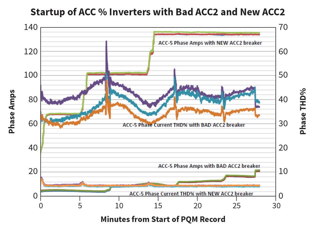
Looking at real circuit waveforms of voltage and current in the AC panelboard, we can see that, immediately after the inverter failure, there is significant harmonic noise on the AC bus. After the breaker is swapped out, the noise drops below the 5% threshold required by IEEE Standard 519 (Fig. 8 on page 34). This data was gathered with a power quality meter at two locations on an operating PV site — both before and after breaker replacement.
Multiple inverters on this site showed component detachment in the harmonic filter section due to melted solder joints, indicating substantial overheating. These units had “heat sink” temperature monitoring via supervisory control and data acquisition (SCADA), which never showed an excessive operating temperature. After replacing all the breakers on the site (35 in total), the harmonics completely vanished. We suggest that when a transformer-less inverter experiences a switch-mode failure and requires replacement, the breaker attached to the specific inverter should also be replaced to avoid this problem.
Failure to replace a single damaged breaker can begin a process that one of the authors has dubbed “breaker cancer,” whereby increased harmonics on a site drive further overheating and damage
to inverters, which can cause further breaker damage. This was the case on the site from which the data in Fig. 6 was gathered. Prior to our involvement, this O&M subcontractor had filed multiple warranty claims with the inverter manufacturer, upgraded the firmware multiples times, and tried all manner of other things. This site showed no visible damage to any of the breakers, and normal multimeters on a site are not sensitive enough to measure the milliohm-level variance between breaker phases that is easily detectable with laboratory-grade measurement equipment.
Devices used to extinguish DC currents, called magnetic blowout devices, have been shown in many studies to provide significant reduction in arcing and faster breaker opening times in DC systems. Designers of AC breakers do not expect the devices to experience DC currents; thus, they usually don’t include magnetic blowout devices. If AC breakers installed in PV or on circuits with inverter switching topologies contained DC magnetic blowout devices, they wouldn’t become damaged or be subjected to overheating.
CONCLUSIONS
AC MCCBs are generally not equipped with DC arc blowout devices — as it is not
Fig. 6. Impedance per phase data.
Courtesy of NREL
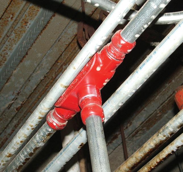
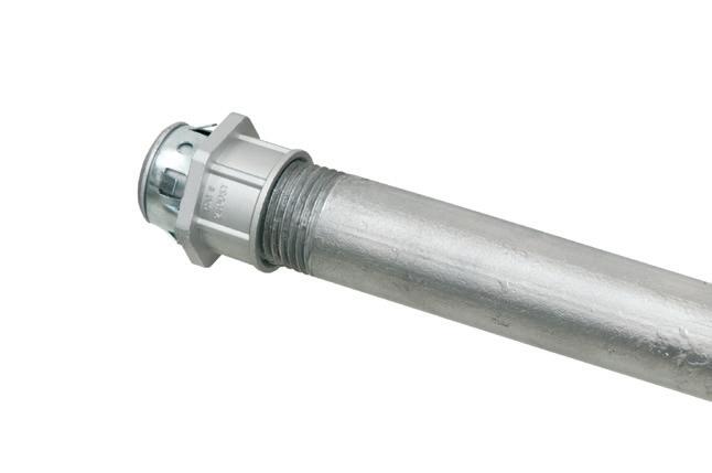
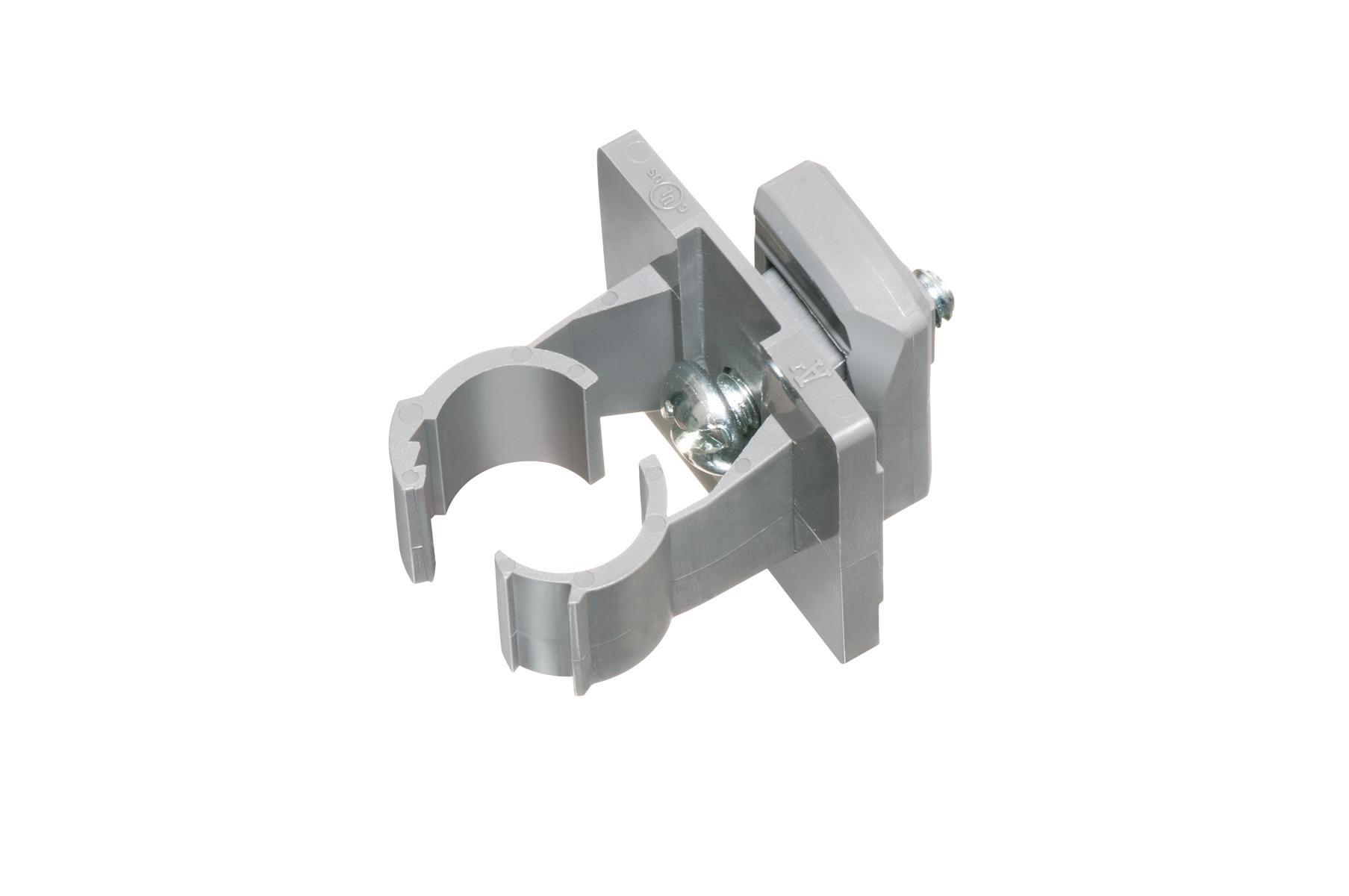
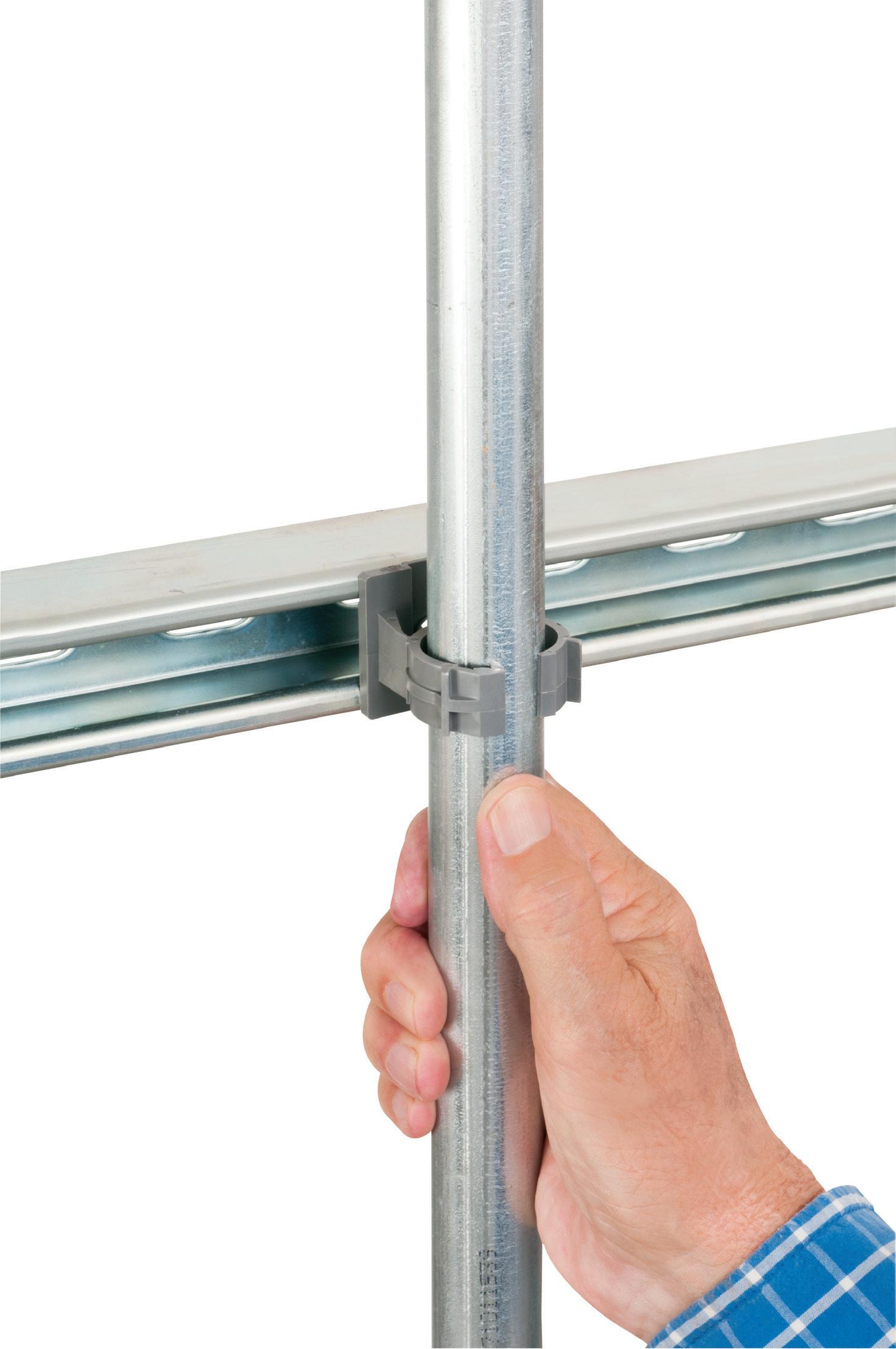
Extra-duty one-piece design
Pre-installed strut clip for faster installation on strut Stainless steel screw
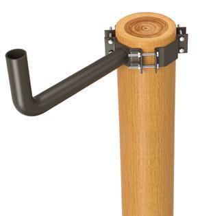
corrosion-resistant QUICKLATCH™ pipe hangers cost the same as a steel pipe hanger with a bolt and nut – but better. They’re faster and easier to install. And SAVE 25 seconds* per installation!
• UV rated for outdoor use
• Listed for environmental air handling spaces
• For thin walls, rigid conduit, PVC conduit or copper
INSIDE PQ
an expected operating mode. They may, however, contain arc chutes or deflector devices, as in the case of at least one device we opened for this study. Arc chutes are used to direct or channel the extinguishing arcs during the normal make/break operations and will do little or nothing to help reduce the arcing under DC current. Understanding how failures in DC-to-AC
inverters, AC panelboards, and breakers propagate is key to ensuring that failures are contained and predictable.
Renewable energy is not the only industry that uses transformer-less inverters, nor is it the only industry that has seen these types of failures. Any transformer-less inverter that interacts with an AC bus is susceptible to these
failures. Safeguards need to be designed into the architecture of the switching network to prevent catastrophic failures and equipment damage and to reduce the possibility of worker injury.
Work has been done in the PV inverter field to design failsafes and proper shutdown of damaged circuits. Unfortunately, several manufacturers are not implementing these designs in a robust manner. Although not required by current codes and standards, it would be a good practice for AC panelboard and breaker manufacturers to add or include proper DC arc extinguishing mechanisms to MCCBs. Until all manufacturers properly design and account for this failure mode in transformer-less inverters, the failures and related PQ issues outlined in this study will continue to plague the renewable energy sector as well as other industries where transformer-less inverters interact with the AC grid (uninterruptible power supplies, for example).
Acknowledgements: This work was authored in part by Alliance for Sustainable Energy, LLC, the manager and operator of the National Renewable Energy Laboratory for the U.S. Department of Energy (DOE) under Contract No. DE-AC3608GO28308. Funding provided by the U.S. Department of Energy’s Office of Energy Efficiency and Renewable Energy (EERE) under Solar Energy Technologies Office (SETO) Agreement Number 30295. The views expressed in the article do not necessarily represent the views of the DOE or the U.S. Government. The U.S. Government retains and the publisher, by accepting the article for publication, acknowledges that the U.S. Government retains a nonexclusive, paid-up, irrevocable, worldwide license to publish or reproduce the published form of this work, or allow others to do so, for U.S. Government purposes.
William Sekulic is a member of the NREL PV Reliability Group, NREL Electrical Safety Committee, a part-time electrical safety officer, a senior member of IEEE, and a registered professional engineer in the state of Colorado.
Greg Linder is a member of IEEE and registered professional engineer in Colorado. He founded SolarSCADA in 2008 and is now SVP of hardware design at Skyfri Corp.
Fig. 7. This needs a caption.
Fig. 8. Breaker per phase current signals before and after replacement of ACC2.
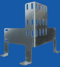
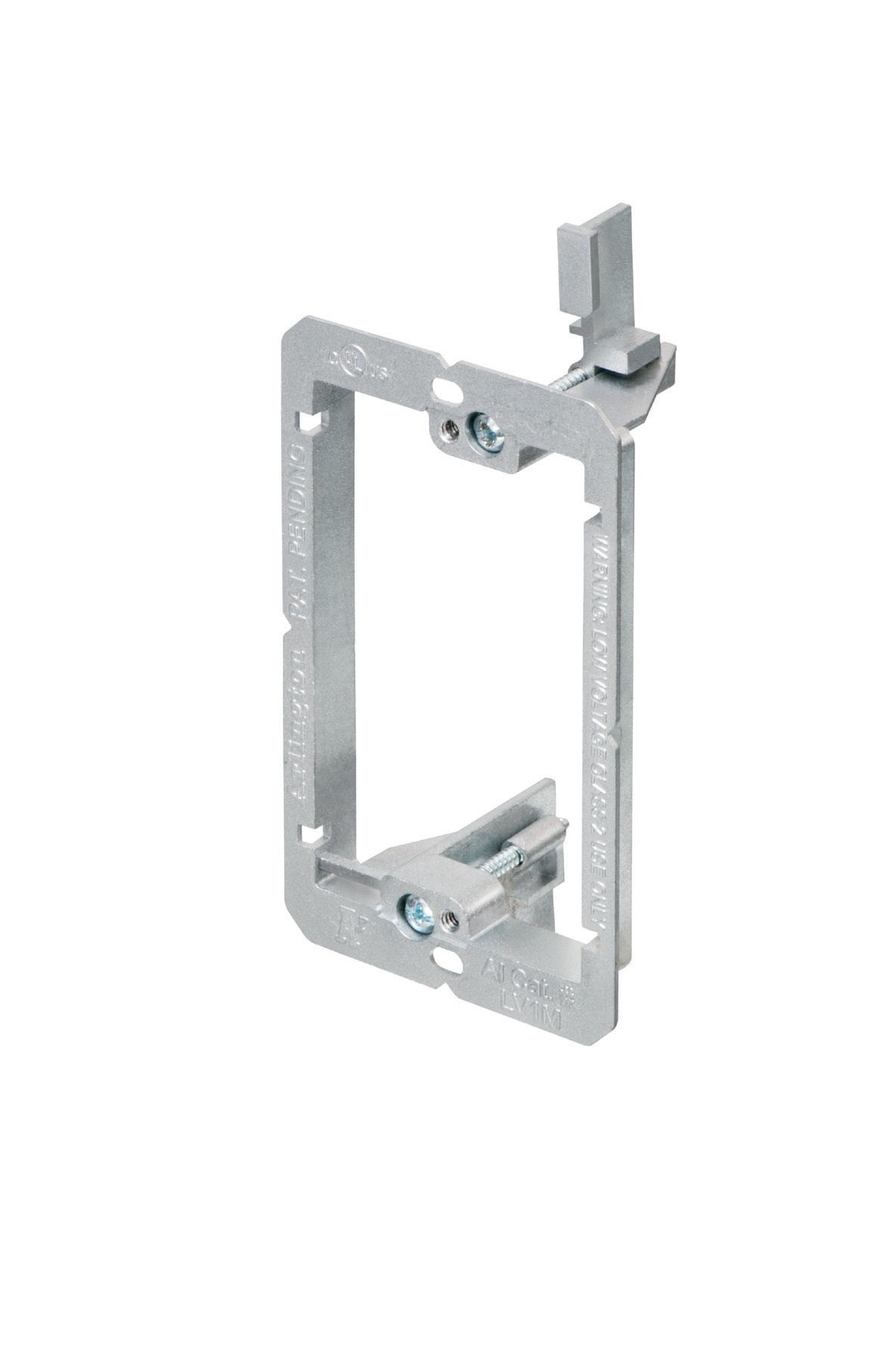
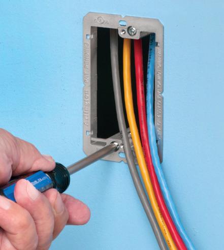
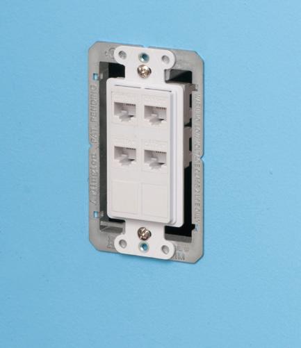
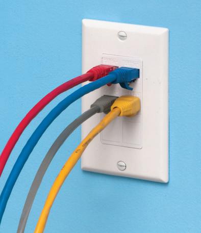
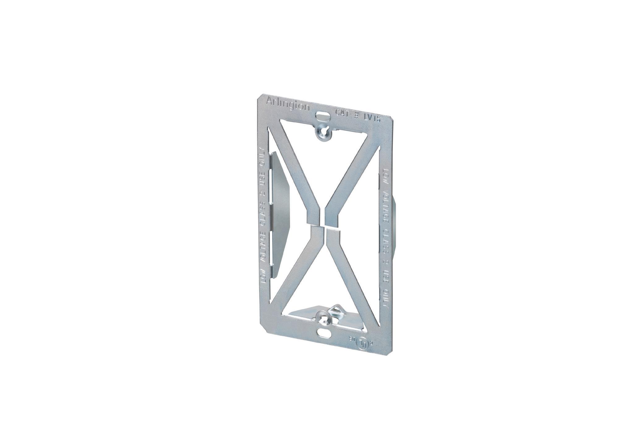
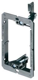
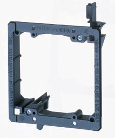
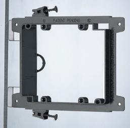
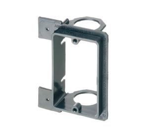
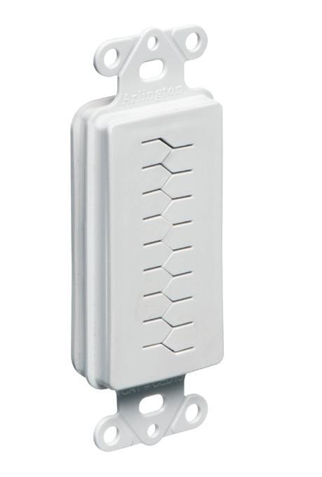
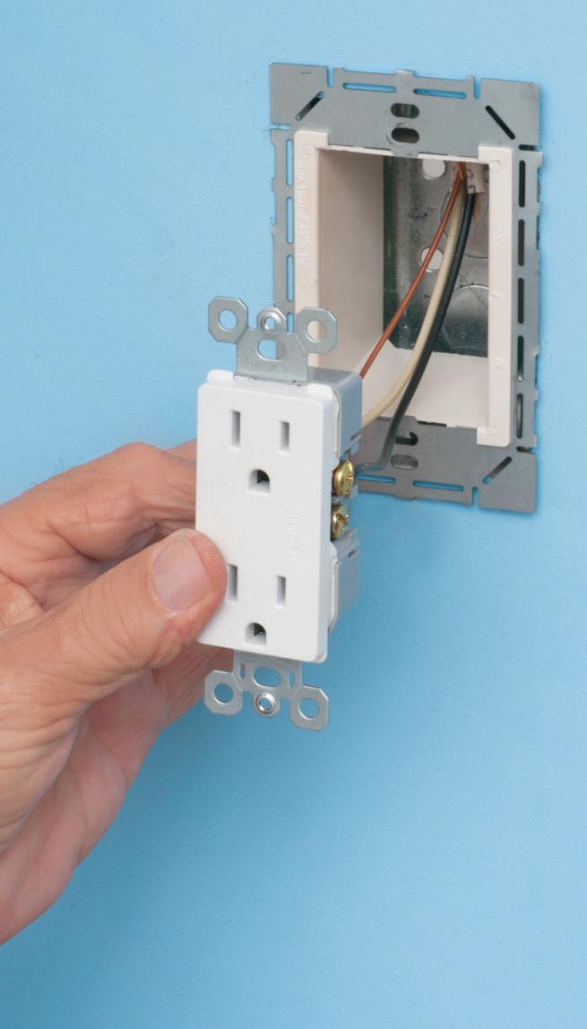
Arlington’s Low Voltage Mounting Brackets are mounting of Class 2 communications, computer and cable TV wiring and connections.
Introducing for EXISTING or RETROFIT construction...
Our
• Extra rigidity and stability where performance and visibility are important or critical
• Threaded holes for easy, fast device installation
• Adjustable bracket for 1/4” to 1” wall board thicknesses
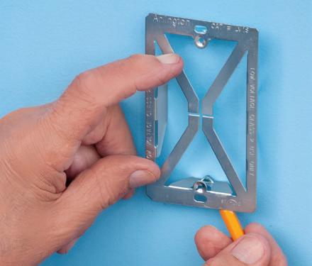
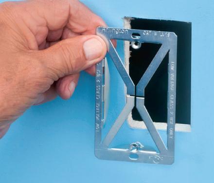
The LV1S PLATED STEEL mounting bracket, with its unique X-shaped bracket design, provides excellent stability and secure installation of low voltage devices in 1/4" to 1-1/4" walls - without an electrical box.
Try them all! Metal and Non-metallic for retrofit, nail or screw-on for new work, and others!
Threaded Holes for easy device installation
Uncovering Common Power Quality Misconceptions
Case studies demonstrate how typical PQ myths can trip up even the most seasoned electrical investigators.
The type and number of electronic loads in customer facilities are truly the cause of a growing number of power quality (PQ) problems. Inevitably, the increasing complexity of these loads — further compounded by the increase in electric vehicle (EV) chargers, the onset of artificial intelligence (AI)-based data centers, and a rise in the number of distributed generation (DG) sources to power customer facilities — will cause further increases in electric utility and customer-based PQ problems.
While specific electrical engineering science must be applied to properly understand, identify, solve, and prevent PQ-related equipment problems in any customer environment, the art of conducting a PQ investigation involves addressing common misconceptions or myths associated with planning and executing an investigation. Doing this will help ensure information critical to the problem is not overlooked.
One must think outside the box and consider all potential causes and how they might be interrelated. Causes associated with the energy source, wiring and grounding system of the facility (and external infrastructures), and the electronic loads must be considered as a complete system. Not all disturbances cause PQ problems — only those that cause the wiring and grounding system
and loads to act up should be considered. One can be assured that some of the causes (and interrelationships) when assembled to understand the dynamic nature of the problem will seem farfetched.
As a seasoned PQ investigator for more than 30 years, these two PQ problems described in this article are among the most bizarre scenarios one engineer has encountered over his PQ career. As one gains various types of PQ experience, such as conducting PQ testing, forensics, investigations, and standards development, we’ve learned facing such scenarios head-on makes a good investigator. This article walks readers through two case studies at customer facilities where common misconceptions were hard at work to derail the PQ investigator. Refer to Table 1 on page 38 for the right questions to ask for guidance on addressing common PQ problems.
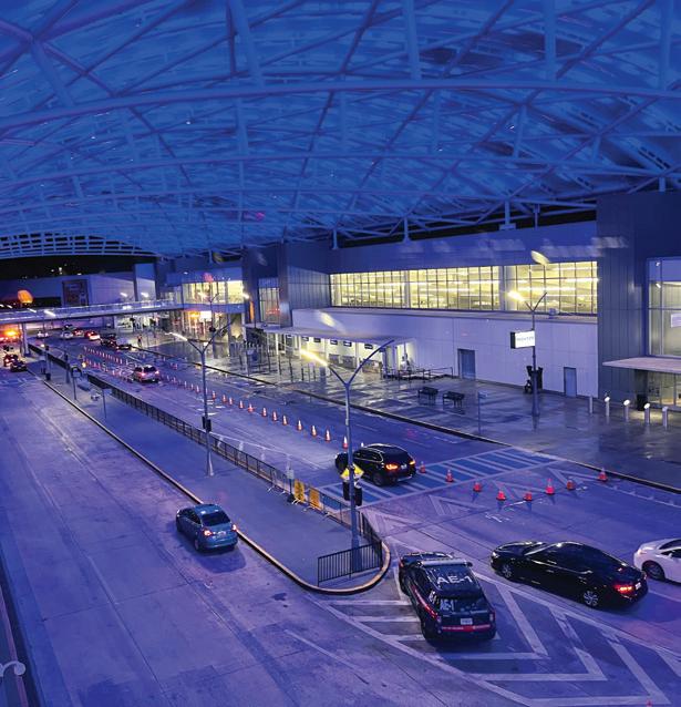
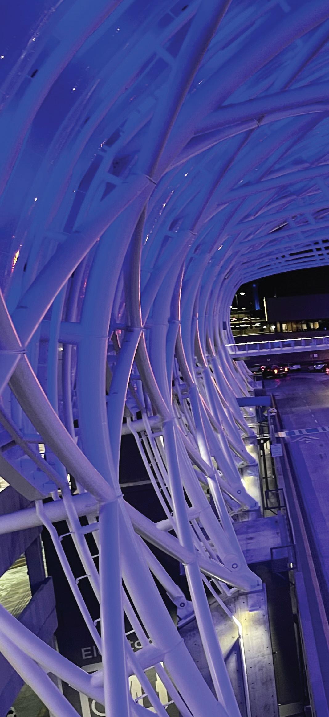
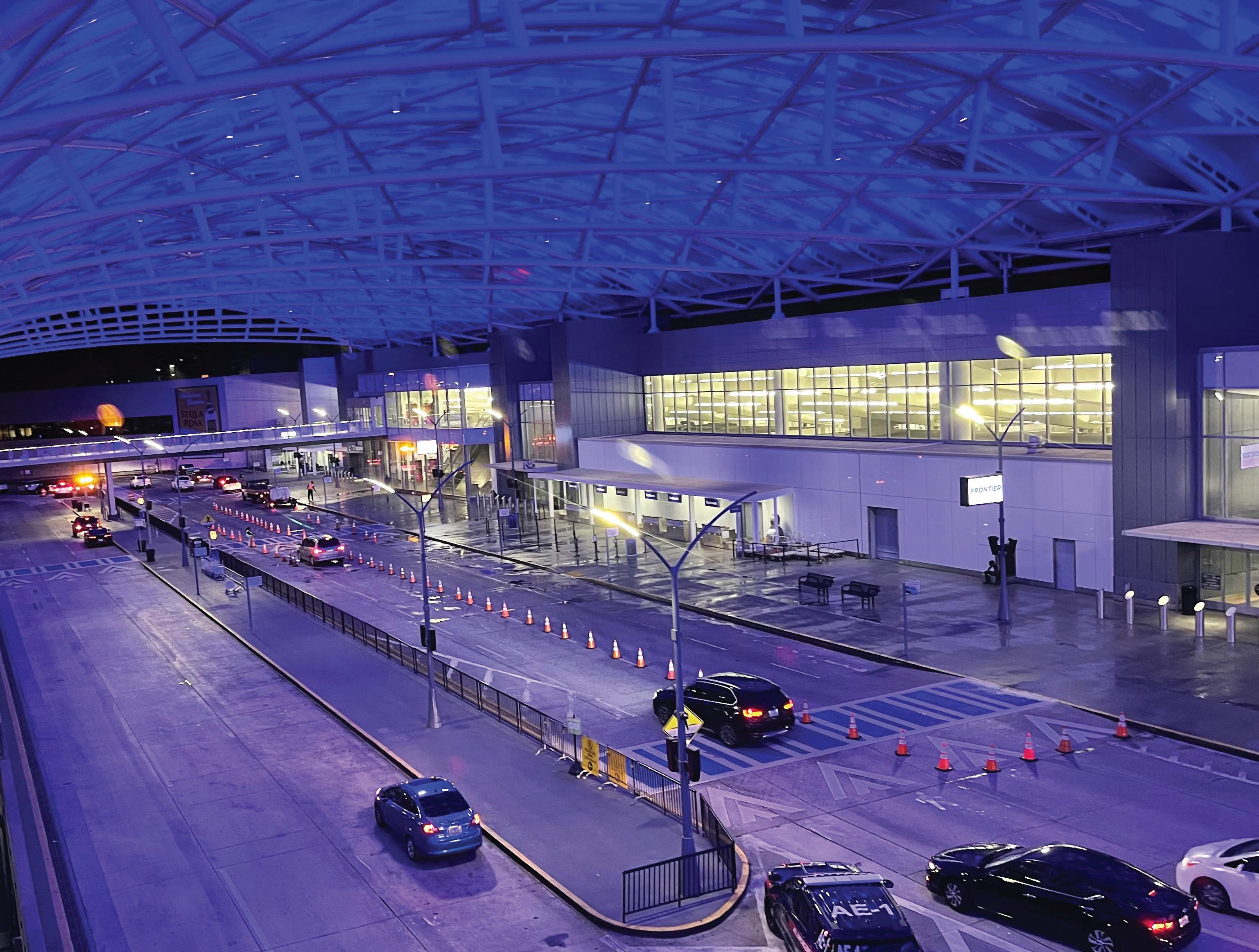
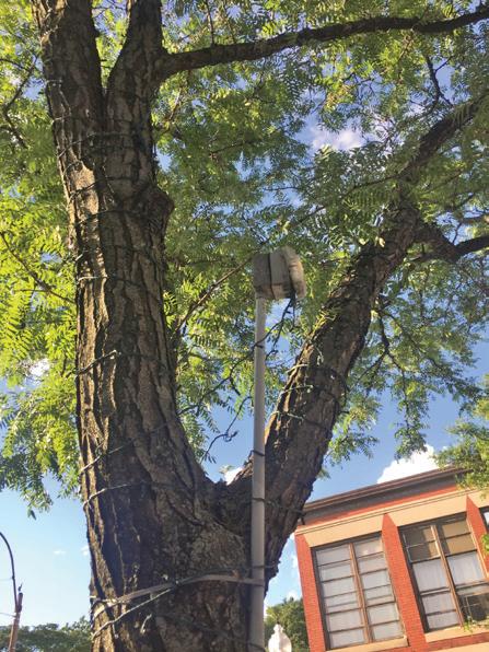
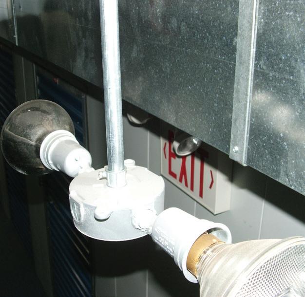
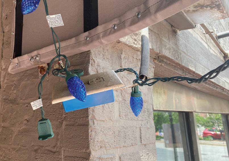
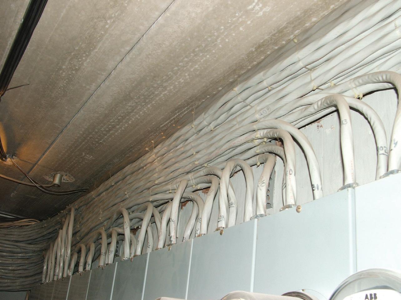
SCENARIO #1. MALFUNCTION OF LED LIGHTING SYSTEM AT MAJOR AIRPORT
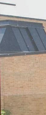
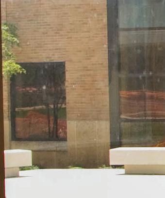
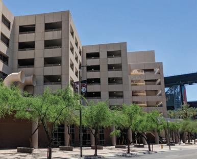
Security and safety in air transportation facilities depend heavily on quality power, especially in a fast-paced global society. To improve security and safety as well as reduce energy consumption in a major U.S. airport, more than 4,000 programmable electronic LED drivers in overhead luminaires were installed along each beam at the top of two new large canopies covering the main passenger
entrance at both main passenger terminals (Photo).
During canopy construction and after commissioning the lighting system, many LED luminaires began malfunctioning (e.g., flashing, flickering, changing colors, etc.) with some failing to illuminate. These problems were very noticeable and could have distracted vehicle drivers and pilots. Aside from the degradation in the illumination level under the canopies, these problems also affected programmed scenes for holidays and special event displays visible to ground and air travelers. This problem presented some very unusual challenges.
WHAT MADE THIS INVESTIGATION UNIQUE?
Investigating PQ problems involving programmable LED lighting equipment can be challenging in any situation. What made this specific situation so bizarre? Following is a list of conclusions derived from troubleshooting, diagnosing, and resolving the underlying PQ issues.
• Highly reliable and quality power from the electric utility’s network underground system was delivered to the airport campus, including the main passenger terminals.
• Footprint of the electrical installation for the AC power system and dual control circuits was large — spanning across both canopies and into the existing infrastructure of both main terminals.
• Malfunctions and failures of LED luminaires occurred on random beam rows and sections on both canopies.
• Some LED luminaires flashed, flickered, and changed colors but continued to illuminate.
• Some LED luminaires changed colors but had no other malfunctions.
• Some LED luminaires had no visible problems but suddenly failed and did not illuminate.
• Malfunctions and failures occurred during construction (as luminaires were tested) and after commissioning. They continued to occur a few years afterward.
• Malfunctions and failures occurred after the replacement of LED drivers of the same design.
• No other indoor and outdoor LED luminaires in the airport experienced these kinds of problems.
• Other outdoor LED luminaires installed on the canopies and along the driveways under the canopies were powered by the same switchgear as the problematic overhead LED lighting but experienced no problems.
• Programmable LED lighting on other similar outdoor installations didn’t exhibit these problems.
• The causes of the LED lighting problems were multilayered, interrelated, and involved all three parts of a PQ problem — the quality of the voltage delivered to the LED drivers, the performance of the infrastructure’s wiring and grounding system, and the PQ immunity of the LED drivers. More specifically, it was the voltage quality at the AC input of the drivers, insufficient surge protection on the lighting control system, problems within the wiring and grounding of the new AC
infrastructure on the canopies and existing AC power infrastructure just inside the terminal, the installation quality and grounding of the lightning protection system (LPS) installed on the canopies, and a “hole” in the susceptibility of the AC input network of the driver design. These five causes worked together to raise the risk of LED lighting problems high enough to cause noticeable LED lighting problems and driver failures.
WHAT MISCONCEPTIONS DID THE CUSTOMER HAVE?
The challenges arising from any PQ investigation invite typical and unique PQ misconceptions. This problem, however, presented a combination of myths. Here are several PQ misconceptions that had to be debunked, resolved, and explained to the customer.
Myth #1: Despite high reliability and quality power meeting industry standards, incoming electric utility power may cause LED lighting problems.
Fact #1: From PQ monitoring, the electric utility power source was ruled
out as causing or contributing to the LED lighting problems.
Myth #2: Sizing surge protective devices (SPDs) internal to electronic loads according to standard industry guidelines will help reduce the risk of premature SPD failure (thus product failure) even when an SPD is applied after an EMI filter.
Fact #2: If sized correctly, the SPD after the EMI filter in the LED drivers can withstand the energy (heat) when a surge occurs. However, the common everyday disturbance (oscillatory wave occurring at the AC voltage peak) from the normal operation of electrical and electronic loads (e.g., escalator VFDs) in the airport terminal was amplified by the driver’s internal EMI filter, which exposed the SPD on the output of the filter to undergo additional heating, leading to its premature failure. Failure of the SPD caused the driver’s AC line fuse to blow.
Myth #3: Application of SPDs along low-voltage control circuits and control system components isn’t needed because control circuits are not power circuits, and the control voltage is low.
Fact #3: Application of properly sized and located SPDs on control circuits is critical to the preservation of the control signal and the protection of the control system components to avoid causing internal damage to the driver, control system components, and driver control functions.
Myth #4: Grounding of the canopies, control system, and LED luminaires installed on the canopies had nothing to do with the malfunctions and failures of the LED lighting system. (Grounding of structures, electrical systems, and electronic loads don’t do anything — so it’s not important. Therefore, questioning it shouldn’t be included in a PQ investigation.)
Fact #4: Grounding of the LED luminaires control system, the driver, and the canopy structure played a key role in the malfunctions and failures of the LED lighting system. (Properly grounding of metal infrastructures supporting LED lighting, lighting fixtures, and the drivers within helps stabilize (keep close to 0V) the whole grounding system, especially when voltage surges try to impact AC power circuits and control circuits.)
Myth #5: New LPS installations on large outdoor metal structures (interfaced with existing LPS-protected
What disturbances can occur on the electric utility system, why do they occur, and where do they come from?
What disturbances can occur by operating electrical and electronic equipment in the customer’s facility, why do they occur, and where do they come from?
How do well-installed (NEC-compliant) building electrical systems react to these disturbances?
How do building electrical systems alter (amplify or attenuate) the disturbances before they reach end-use equipment?
Electrical and Electronic Equipment
How do electrical loads (e.g., motors without VFDs) and electronic loads (VFDs, power supplies, EV chargers, etc.) react to the altered disturbances?
How and why do some loads interact to cause one or both loads to act up?
Table 1. Some questions to answer to avoid PQ misconceptions and myths.
buildings) that must support programmable LED lighting will perform the same as LPSs installed on large building structures that must support programmable LED lighting.
Fact #5: Careful installation and evaluation of the bonding of the components of the metal structure and the bonding of LPS connector hardware and its down conductors must be carried out to ensure the LPS system operates under low impedance conditions to help ensure adequate protection and performance of electronic loads like LED lighting. This type of installation is not the same as what you find on a typical building structure.
Myth #6: Malfunctions and failures of the LED lighting equipment (drivers and control system components) were associated with one simple cause.
Fact #6: Most PQ-related problems with electronic loads, especially controllable loads like most LED lighting, involve more than one cause and are complex.
Myth #7: Thunderstorms passing over large metal structures that must support electronic equipment are typically the single disturbance cause of PQ-related equipment problems.
Fact #7: Since the canopies were constructed from large steel beams exposed to the outdoors, lightning from passing thunderstorms was not the only contributing cause to the malfunctions and failures of the LED lighting system. The oscillatory disturbance caused by the power electronics inside the VFDs controlling the elevator motors was the second disturbance cause that impacted the LED drivers.
WHAT COMMON CULPRITS WERE FOUND?
Table 2 on page 40 lists the common and uncommon causes found inside the airport terminal and on the canopies. In the terminal, the electronic loads (e.g., VFDs) were acting as the source of the disturbances, and its electrical system couldn’t provide a stable neutral and ground system. On the canopies, the voltage immunity of electronic loads (e.g., LED drivers) allowed the oscillatory surges from the operation of the VFDs on the elevators to damage the metal oxide varistor (MOV) downstream of the EMI filter (the MOV on the input of the EMI filter was not damaged). The grounding problems found on the canopy’s electrical system and its LPS compromised the voltage reference for the canopy-mounted controls as well as the LED drivers.
WHAT DISTURBANCES MADE THE PROBLEM MORE DIFFICULT TO INVESTIGATE?
Voltage sags did occur on the electric utility power source but posed no problems to the operation of the canopy’s LED lighting and other electrical systems. One added challenge to this investigation was the identification of the oscillatory surge waves (occurring at the voltage peak) generated by the operation of the VFDs on the elevators that operated 24 hours per day.
A second more complex challenge was explaining why the EMI filter inside the LED driver amplified the oscillatory wave increasing its threat
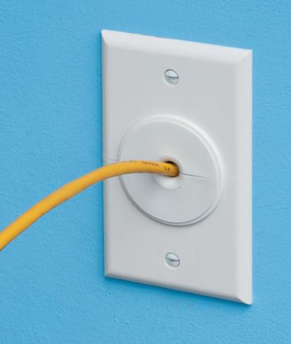
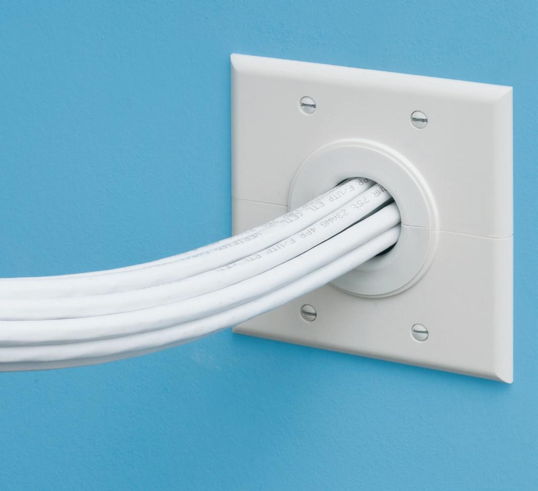
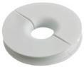
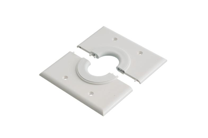
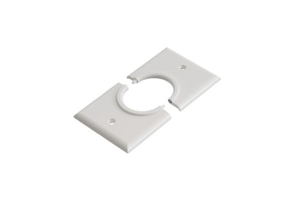
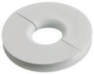
Arlington’s non-metallic Split Wall Plates provide a simple and effective way to accommodate pre-connectorized low voltage cable(s) of varying size and quantity or pre-existing low voltage cables.
Multiple split grommets are provided with our single- and two-gang wall plates for increased versatility in effectively sizing and covering the hole/opening. Use as shipped, or with one of the supplied bushings to alter the size of the opening.
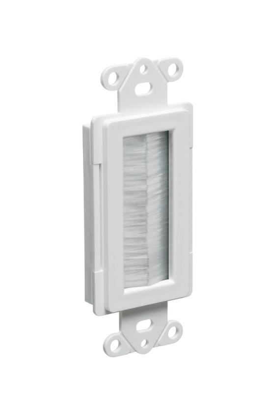
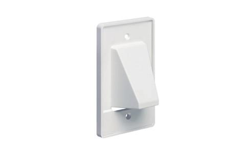
The SCOOP™ series of reversible, non-metallic ENTRANCE HOODS, PLATES AND DEVICES protect cable while delivering good looks and installation versatility. They also reduce labor and eliminate extra connections.
Our newest CABLE ENTRY DEVICES come with or without a wall plate for efficient cable management.
HOODS for decorator-style wall plates, single and two-gang PLATES install facing in or out...and save time!
• Low voltage cable protection
• Best way to run cable
to the second MOV. Normally, the magnitude of these waves poses no problem to electronic loads if proper surge protection is designed in. However, because the EMI filter in the LED driver amplified the waves, the SPD on the output of the filter experienced too much heating.
HOW AND WHY DID NORMAL ELECTRIC UTILITY SYSTEM OPERATIONS MAKE THIS PROBLEM DIFFICULT TO INVESTIGATE?
Because voltage sags were found to occur on the circuit powering the canopies, some end-users were concerned that the sags were causing the LED lighting malfunctions and failures. The fact that this circuit was a network underground circuit also made the investigation challenging, since fewer disturbances occur on these circuits.
SCENARIO #2. UNCOMMON PQ CULPRITS CAUSE LONG-TERM INTERRUPTIONS AT LARGE PARCEL SORTING FACILITY
A large parcel sorting facility is powered by an on-site 115kV to 12.47kV customer substation feeding a double-ended 12.47kV switchgear system powering one 12.47kV to 4.16kV transformer. Four downstream switchgear systems with 4.16kV to 480V step-down transformers fed 480V power distribution systems powering a plethora of nonlinear electronic loads (e.g., VFDs, PLC, power supplies, electronic lighting, etc.). Four soft-start chillers (three large and one small) are powered by the 4.16kV bus. The facility uses a large number of VFDs (1 hp to 250 hp) to move parcels 24 hours a day.
The facility experienced some long-term power interruptions. Each interruption created two to three hours of downtime not including time to restart each machine. Moreover, the plant often experienced problems with restarting sorting systems after an interruption. Plant downtime caused delays in sorting parcels and reloading outgoing trucks, which caused late deliveries of packages to customers and delays in receiving new parcels from incoming trucks. The PQ problems caused significant time delays and financial burdens, especially during the holidays.
Electrical Power Quality Disturbance Source Main passenger terminal
Wiring & Grounding
Lightning Protection System (LPS)
Main passenger terminal and canopy electrical systems
Type – Oscillatory (e.g., capacitor switching)
Source – Electric utility capacitor banks
- Loose connections on phase, neutral, and ground conductors on lugs
- Missing & improper ground bonds in panels
Type – Oscillatory (e.g., switching of power electronics in electronic loads)
Source – VFDs on elevators in passenger terminal
- Corrosion on neutral bars
- Corrosion on equipment grounding bars
- Missing & improper ground bonds on canopies
- Improper installation
- Loose connections
Main passenger terminal and canopies
Power Quality Voltage Immunity of Electronic Load
Programmable LED lighting installed in the ceiling of canopies
- Damaged and toppled over air terminals
- Improper maintenance
- Corrosion of connections
- No surge protection on mains
- No surge protection on the input of the load’s AC network
- Improperly installed surge protection on mains
- Corrosion under newly installed equipotential bonding connectors on canopies
- Insufficient bonding on canopy beams
- Improperly welded down conductor cables to ground rods in newly installed test wells
- Inability to bond canopy LPS to terminal’s LPS
- No surge protection on control circuits
- No coordination of surge protection (power & control)
- Amplification of oscillatory surge caused by EMI filter
- Undersized SPD on the output of the EMI filter
2. Common
WHAT MADE THIS CASE UNIQUE?
Investigating PQ problems involving the long-term interruption of power to an industrial facility is not typically challenging. However, multiple causes working together to cause the interruptions and the large number of end-use equipment problems at this facility/the time it took to identify and fix all of them proved to be quite challenging. Here’s a list of the problems identified.
• 115kV primary side electric utility transmission system fuses at the customer’s substation blew eight times in one calendar year with the first event during the early morning hours of January 1st.
These events occurred during all sea sons, on various days of the week, and at random times of the day.
• The footprint of the industrial facility was large and used a large number of vintage VFDs ranging from 1 to 250 hp. (VFDs can be linked to a wide variety of PQ problems and should always be considered as a potential culprit.)
• The causes of the 115kV fuses blowing were multilayered and involved all three parts of a PQ problem — the electric utility source (5MVA transformer stepping 115kV down to 4.16kV), the power distribution system inside the facility, and the characteristics of the non-linear electronic loads (i.e., VFDs). Cause
Table
and uncommon causes pinpointed in failures of the LED lighting system on canopies in an airport.
17SAVE seconds
Fully assembled, SNAP2IT® fittings handle the widest variety of MC cable AND THE NEW MC-PCS cables.
Compared to fittings with a locknut and screw, you can’t beat these snap in connectors for time-savings!
LISTED SNAP2IT ® CONNECTORS FOR NEW MC-PCS CABLE ...lighting & low voltage circuits in the same cable
• Fits widest range and variety of MC cable 14/2 to 3/3
AC, MC, HCF, MC continuous corrugated aluminum cable and MCI-A cables (steel and aluminum)...including the new MC-PCS cable that combines power and low voltage in the same MC cable
ANY Snap2It Connectors LISTED for MC cable are also LISTED for MC-PCS cable! These products offer the greatest time-savings.
• Fast, secure snap-on installation
• Easy to remove, reusable connector From cable Loosen screw on top. Remove connector from cable. From box Slip screwdriver under notch in Snap-Tite® Remove connector.
Easy to Snap into Box!
• There was no pattern to the interruptions regarding the primary phase, month, day, or time of day.
• The 5MVA utility-owned transformer was only half-loaded but was original to the site.
• The first fuse-blowing event (January 1st) revealed a failure of the terminations where the bare electric utility substation conductors to insulated medium-voltage (MV) cable going underground to the customer’s 12.47kV switchgear were joined.
WHAT MISCONCEPTIONS DID THE CUSTOMER HAVE?
The challenges arising from any PQ investigation invite typical misconceptions. This problem, however, presented a combination of misconceptions that required careful thought during the investigation. Following is a list of PQ misconceptions present in this case.
Myth #1: Failures of primary side fuses upstream of a normally loaded transformer (i.e., under the unit’s rating) are never related to the customer’s load, especially when the substation transformer is half-loaded.
Fact #1: Always consider the static and dynamic PQ characteristics of the customer’s load when investigating any fuse failures. Fuses use fuse links that have specific time-current characteristics that represent the current squared (I2) and the time (t) it takes for the fuse to melt (i.e., increase the link’s temperature), and the melting point are ratings that help ensure the heat caused by all currents flowing through a link has enough time to flow away from the fuse to its connected circuitry. Expected fault currents (occurring less frequently) and their duration and inrush currents (occurring more frequently from the starting of large loads) and their duration are examples of dynamic PQ characteristics. For example, 60-Hertz steady-state currents are static PQ characteristics. Fuses with higher I2t values can handle larger current surges for longer durations before blowing. However, harmonic currents, which typically range from 120Hz to 3kHz, cause fuse link heating, are also steady-state currents that are static PQ characteristics drawn by electronic loads and the effects of such are not included when testing fuses to industry standards. The true RMS current that fuses
Source-Related Cause (115kV Primary Side Fuses)
Customer’s Power Distribution System
Primary side of utility power system circuit
- Consistent high outside temperatures causing normal derating of 115kV fuses
- Fuse blowing events occurred in winter, spring, summer, and fall
- Outside temperature was not the consistent primary cause of fuse failures
- Voltage imbalance
- Overloaded phase(s)
- Power transformer issue (e.g., oil impurities)
- Loose connections in primary circuit
Customer’s upstream and downstream MV-to-LV stepdown transformers & switchgear systems
Load Characteristics (Cyclical)
PQ of Load Characteristics (Harmonics)
Chiller plant
- Positive DGA test results (MV-to-LV transformer on its way to failing)
- Multilayered causes related to source, customer’s power distribution system, and electronic loads
- Outside temperature increased number of fuse blowing events in hot weather
- Typical causes of fuse blowing were not occurring
- No other fuses (utility or customer side were failing)
- LV-to-MV transformers not overloaded, or K-factor rated
- None of the feeder or branch circuits were overloaded
- Start up characteristics of each chiller allow chillers to start too close together in time, compounding effects of inrush current from compressor motor starting
Parcel sorting production lines powered by all four switchgear systems
- One or more feeder and/or branch circuits were overloaded
- Operation of VFDs on production lines starting too close together in time
- Load (current) imbalances
- Three (two large and one small) chillers were not functional
- One large chiller “seemed” to be operating normally (i.e., the facility was properly cooled)
- Wide vintage of VFDs were in use
- Wide range of VFD horsepower’s were in use
- Some VFDs and PLCs found damaged and could not be restarted
Table 3. Common and uncommon causes found in case study No. 2 — multiple failures of 115kV electric utility primary side fuses from use of large linear loads and many electronic loads in parcel sorting facility.
will respond to includes the static and dynamic current characteristics.
Myth #2: Failures of MV terminations (electric utility side to customer’s MV cable) exhibiting heating at the joint are always related to termination characteristics (e.g., high resistance developing over time) and exposure to its surrounding environment (the substation was in use for over 20 years).
Fact #2: Other PQ-related causes related to the electric utility source, customer’s power distribution system, and electronic loads can lead to termination failures.
Myth #3: The blowing of any electric utility primary side fuse is caused by one single PQ phenomenon.
Fact #3: Fuses will respond to multiple types of PQ phenomena: voltage or current imbalance, overloading, inrush current, load profile (i.e., how often the load is stopped and started), harmonics, and temperature.
Myth #4: Blowing of electric utility side fuses is always caused by an electric utility PQ problem. In PQ, poor voltage PQ can impact the customer’s electrical system and its loads. Poor current PQ
(Continued on page 61)
MC CABLE FITTINGS
each fitting also comes with end stop bushings that accommodate different size cable bundles. ONE trade size fits SEVERAL cable types and sizes, plus flexible metal conduit for super convenience and cost-savings! Reduces inventory and material handling too.
Refer to spec sheet for specific end stop sizes Listed for FMC
What is power factor, and why do you need to know about it?
By David Colombo, PE, Power Engineers, LLC
Understanding power factor (PF) is important because it gives us a clear understanding of the efficiency of an electrical system. Put simply, it’s the ratio of true power and apparent power, which represents how much power supplied by the source will perform useful work. A unitless number used in alternating current circuits, PF can be used to refer to a single piece of equipment (such as an induction motor) or for the electricity consumption of an entire building, facility, feeder, etc.
Power factor correction capacitor bank.
FLOOR BOX
(3) FLBC8500 boxes
a two-gang box. Add another for three-gang! FLBC8500 Single gang box
Single gang
FLBC8510BR Brown
FLBC8510BL Black
FLBC8510GY Gray
FLBC8510CA Caramel
FLBC8510LA Lt Almond
Two-gang
FLBC8520BR Brown
FLBC8520BL Black
FLBC8520GY Gray
FLBC8520CA Caramel
FLBC8520LA Lt Almond
Three-gang
FLBC8530BR Brown
FLBC8530BL Black
FLBC8530GY Gray
FLBC8530CA Caramel
FLBC8530LA Lt Almond
Build a two- or three-gang concrete floor box by simply locking single gang boxes together!
Then buy the UL LISTED single, two- or three-gang cover/frame kit, with devices included, in PLASTIC, FIVE COLORS – or in economical diecast zinc with a brass or nickel finish. Fast, easy installation.
Cover installs with hinge on either side.
Two-gang FLBC8520MB
Three-gang FLBC8530MB
(1) FLBC8530BL Black plastic cover/frame kit
FLBC8530MB
The Power Triangle
Why Fix Poor Power Factor?
Poor power factor means more power is drawn
Requires larger cables
Reactive power penalty fee
Losses, high heat gains, and reduced equipment life
Voltage drops
= SIN
= KW2 + KVAR2 = KV * I * 3
Power factor triangle.
When the PF is 1.0 (called unity), it means that the resistive load will consume all the power supplied by the source and convert it into another form of useful energy. If the PF is 0.0, it means all the power from the source is entirely reactive and will be stored in the reactive load and returned to the source. See the Equation below.
Power Factor = True Power (kW) Apparent Power (kVA)
A common analogy used to explain PF is a nice cold pint of beer. We pay for a beer by the glass, but inside the glass, there is both beer and foam. The more beer we have, the less foam there is — so we get good value for our money. If there is a lot of foam, then there’s not a lot of beer — and we’re not getting good value for money. The beer represents our true power or kilowatts (kW). This is the useful stuff we want and need. This is what does the work. The foam represents our reactive power or our kilovolt-amps reactive (kVAR). This is the useless stuff.
poor PF?
There will always be some in the glass, and we have to pay for it. However, because we can’t use it, we don’t want too much of it. The combination of kW and kVAR is our apparent power or our kilovolt-amps (kVA).
A perfect PF would be 1.0 or unity, but except for a purely resistive load, this would be counterproductive because that will create resonance. A good PF would be 1.0 to 0.95. An acceptable PF is between 0.95 and 0.8. Anything below 0.8 needs improvement or power factor correction (PFC). The Figure above has some useful formulas and the most common representation (power triangle).
What causes a low PF? Certain equipment is highly inductive and sources of reactive power (kVAR), including:
• Transformers
• Induction motors
• Induction generators
• HID lighting
These types of indicative loads can constitute a major portion of the power consumed in industrial complexes. Improving the PF can maximize current-carrying capacity, improve voltage to equipment, reduce power losses, lower electric bills, and avoid PF penalties (typically occurring below 0.9 PF), as shown in Table 1
When the PF is low, this means that the electrical system has low efficiency. The major effects of low PF are:
• The system would draw a much higher current for real and reactive power, which increases line losses and hence the heat.
• Larger conductor sizes and switch gears are required to compensate for the line losses, which make this a costly exercise.
PF CORRECTION
The simplest way to improve PF is to add PF correction capacitors to the electrical system. PF correction capacitors act as reactive current generators, helping to offset the non-working power used by inductive loads, thereby improving the system PF. The interaction between PF capacitors and specialized equipment, such as variable-speed drives, requires a well-designed system.
The most practical and economical PF correction device is the capacitor. It improves the PF because the effects of capacitance are exactly opposite those of inductance.
The VAR of kVAR rating of a capacitor shows how much reactive power the capacitor will supply. Since this kind of reactive power cancels out the reactive power caused by inductance, each kiloVAR of capacitance decreases the net reactive power demand by the same amount. A 15-kVAR capacitor, for example, will cancel out 15 kVA of inductive reactive power.
Capacitors can be installed at any point in the electrical system and will improve the PF between the point of application and the power source. However, the PF between the load and the capacitor will remain unchanged. Capacitors are usually added at each
Table 1. Why correct a
Table 2. Summary of facility metering.
Arlington’s steel SliderBar™ offers the easy, NEAT way to mount single or two-gang boxes between wood or metal studs with non-standard stud cavities.
No more cutting, nailing and fitting extra 2x4s to fill the space! SliderBar saves about 20 minutes per box. Designed for studs spaced 12” to 18” apart, SL18 allows positioning of one or more boxes anywhere in the stud cavity.
• Bending guides on bracket assure proper positioning on studs
• Pre-punched pilot holes on BOTH sides of S for easy attachment of one or two boxes
Safety Matters
This twice-a-month e-newsletter delivers the latest trends and information on electrical safety, reports on specific accidents in the field, and provides tutorials and evergreen safety content that can be used for reference and training.
Topics covered include:
• Best practices for safely working on electrical equipment
• Accidents and investigations
• Arc flash
• PPE
• Shock and electrocution
• Fire and security
• Safety audits
Subscribe Today
See all of our EC&M e-newsletters at www.ecmweb.com
Resultant PF with a new capacitor.
piece of offending equipment, ahead of groups of motors (ahead of motor control centers or distribution panels), or at main services.
PF correction capacitors can switch on every day when the inductive equipment starts. Switching a capacitor on can produce a very brief over-voltage condition. If a customer has problems with variable-speed drives turning themselves off due to over-voltage at roughly the same time every day, investigate the switching control sequence. If a customer complains about fuses blowing on some (but not all) of their capacitors, check for harmonic currents.
There are two types of capacitor banks: fixed and switched. A fixed bank is connected all the time and continuously supplies reactive power (VARs) into the system to compensate for a low PF. The downside of a fixed bank capacitor is that during periods of light load (i.e. nights, weekends, etc.) this additional compensation can produce higher than normal voltages, which can be damaging to sensitive electronic equipment.
A switched (or automatic) capacitor bank monitors the electric service continuously and switches on the capacitors only when needed. This type of system prevents damaging overvoltages and improves the PF to unity (1.0). The intelligent controllers of switch capacitor banks use a voltage override feature to disconnect the capacitor bank if the system’s primary voltage is too high.
INSTALLATION EXAMPLE
A large manufacturing facility was receiving electric utility penalties for poor PF. The facility was fed through a 2,000 kVA transformer to a 3,000A, 480V main switchboard. When the PF fell below 0.9 lagging, the electric utility switched demand billing from kW
to kVA, which can increase the demand charge significantly. This can be seen in Table 2 on page 46, which shows a summary of the facility’s maximum, minimum, and average demand (kW and kVA) and PF.
As can be seen, with a PF below 0.9 and a switch to kVA demand from kW, the increase can be several hundred kW/ kVA each month, costing the facility significant money. Based on a reactive power range of 424 kVAR to 898 kVAR during the 12 months of metering, three different sizes of capacitor banks were evaluated: 300 kVAR, 450 kVAR, and 600 kVAR. For each, it was calculated as to what the reactive compensation would be, as summarized in Table 3
The 600-kVAR capacitor bank would correct the PF to near 1.0 but would cause the facility to go leading PF during periods of light load. This option wasn’t recommended due to the possibility of voltage rise/increase. It is recommended that a 450-kVAR capacitor bank be installed, which will improve the building PF from its present range of 0.78-0.91 to 0.96-0.99. This improvement in PF will reduce the flow of reactive power (VARs) into the building and allow more real power (watts) to flow from the transformer. A switched capacitor bank in 50-kVAR increments was recommended to better regulate the PF as the facility load increases or decreases, as shown in the Photo on page 44.
Financial payback for an installation of a PF correction bank can be on the order of only on to two years, depending on the penalties being assessed for low PF.
David Colombo, P.E. is a Professional Engineer located in Massachusetts, and the owner and principal of Power Engineers, LLC, a design, engineering and consulting firm.
LISTED BOX EXTENDERS
Arlington’s variety of cULus Listed Box Extenders extend set back electrical boxes up to 1-1/2”.
Made of heavy-duty, 105°C continuous use 94V0 rated, flame retardant plastic, they level and support wiring devices, while protecting wires against damage and stripping.
Choose the one that’s right for you!
BE1, BE2, BE3, BE4...Single-, two-, three- and four-gang, and BE1R for round or octagonal boxes...
Box Extenders
device support in oversized or mis-cut wall openings, available in single-, two-, three- and four-gang, (patented BE1X, BE2X, BE3X, BE4X.)
Our new heavy duty, COMMERCIAL-GRADE steel support plate! As shipped, single and two-gang BE1XLS and BE2XLS work with maxi cover plates, but they’re and standard plates. Convenient. Saves time. Great for poorly cut drywall.
For all standard devices, switches and GFCIs, our box extenders comply with NEC Article 314.20 for set back boxes.
Presenting the most bizarre electrical installation mishaps of last year that violated the 2023
NEC.
By Ellen Parson, EC&M
As we reflect on 2024 from an editorial standpoint, evaluating which topics performed best and why, EC&M readers continue to rank the “National Electrical Code” as the most-important subject we cover. As a result, it’s no surprise that the “Top 10 Craziest Code Violations of 2023” was one of our most popular photo galleries of last year — ranking up there with the “Top Changes to the 2023 National Electrical Code” article and accompanying photo gallery.
So, back by popular demand, here are the most extraordi nary Code violations uncovered by our NEC Consultant Russ LeBlanc in 2024. Shoddy electrical installers beware: If you’re behind an electrical installation gone wrong like those featured here, there’s a good chance your handiwork may turn up in the pages of EC&M or on our website someday soon. Note: All references are based on the 2023 edition of the NEC.
STEEL
SNAP2IT® CONNECTORS
TINTED 40STS
the cable into the connector and rotate it clockwise.
Available in 3/8" trade size, both connectors install into a 1/2" knockout, and are listed for steel and aluminum AC, HCF, MCI and MCI-A cable. The tinted 40STS has more room inside for easier cable insertion.
In Canada both connectors are Listed for use with AC90 and ACG90 cable.
• Tested to UL 514B and Listed to meet UL ground fault requirements
• Removable Unscrew the connector counterclockwise to remove it from the cable. Remove the connector from the box using a flat blade screwdriver. Release the snap tangs from the inside of the box while pulling the connector out of the knockout.
• Packed in heavy-duty, 200 piece boxes
CATALOG NUMBER CABLE RANGES STEEL Snap2It® connectors
38STS AC, HCF, MCI, MC!-A 14/2 w ground, 14/3, 14/2 12/2 w ground, 12/3, 12/2 • 10/2 w ground, 10/3, 10/2 .405” Dia. Minimum to .605” Dia. Maximum
40STS AC, HCF, MCI, MC!-A
Tinted 12/2 w ground, 12/3, 12/2 • 10/2 w ground, 10/3, 10/2 .480” Dia. Minimum to .605” Dia. Maximum
120A
38STS
If those vines keep growing, it won’t take long for the service disconnect and the metering equipment to be completely enveloped and unrecognizable. Russ felt bad for any workers needing to work on that disconnect, especially if there is any poison ivy growing amongst those vines. He was itchy just thinking about it. While this installation may have complied with Sec. 230.70(A)(1) requirements to be “readily accessible” when it was initially installed, the vines and other vegetation growing all over the side of this building currently create obstacles that would need to be removed in order to access the equipment. This equipment is no longer “readily accessible.” Would a person be able to turn off the power quickly in an emergency? Or would those vines restrict the movement of the disconnect handle? There are not many Code rules written about vegetation, but installers must be aware of the surroundings and the possibility of any future vegetation growth that may create problems or hazards for the electrical installation. In this case,
A DISAPPEARING ACT
the vegetation should be cut back and maintained in a manner that permits
NOT A BUNDLE OF JOY
The only supports for most of these cables are the other cables. There are a few pieces of strut secured to the plywood behind this massive bundle of cables, but only the first layer of
cables is secured to that strut with cable ties — and that first layer of cables is used to support every additional layer of cables. Section 300.11(D) prohibits cable wiring methods from being used
safe, Code-compliant access to this electrical equipment.
as a means of support for other cables, raceways, or other equipment. Russ couldn’t be sure of the exact number of cables in this gigantic bundle, but it is approximately 60 apartment feeder cables. That amount of cables makes him wonder if the installers accounted for the number of current-carrying conductors when determining the cable ampacity. Since these cables are installed without maintaining any spacing between them, Sec. 310.15(C)(1) requires their ampacity to be reduced in accordance with Table 310.15(C)(1). Since there are more than 41 currentcarrying conductors in this bundle, an adjustment of 35% of the ampacity value in Table 310.16 must be used. The writing on the cable jackets indicated that these cables contain 4 AWG aluminum XHHW conductors. Table 310.16 has 4 AWG aluminum XHHW being rated for 75A. Normally, that might be perfectly fine for a 60A feeder for an apartment. But, when you apply the 35% adjustment factor, it brings the ampacity down to only 26.25A.
AWFUL AWNING LIGHTING INSTALLATION
This hookup was spotted underneath an awning installed above the entranceway to a local business. There are many
problems to point out here. The lack of support for the box is one big problem. The conductors are literally supporting
WHERE’S THE BOX?
the box. This does not comply with any of the box support requirements in Sec. 314.23(A)-(H). Another huge problem with this installation is the lack of an equipment grounding conductor (EGC). The liquidtight flexible nonmetallic conduit (LFNC) only contains a black and white conductor. Section 406.4(B) requires an EGC to be connected to the grounding terminal of the duplex receptacle. This non-weather resistant duplex receptacle does not comply with either Sec. 406.(9)(A) for damp locations or Sec. 406.9(B) for wet locations. The enclosure for the duplex receptacle also does not comply with either of those two Sections. Finally, the incomplete LFNC raceway does not comply with Sec. 300.12. The exposed THWN conductors are not sunlight resistant as specified in Sec. 310.10(D). Based on all the visible problems here, Russ doubts any GFCI protection is provided for this duplex receptacle as required by Sec. 210.8(B)(6). All in all, this was a pretty scary installation.
Some readers may be old enough to remember the catchphrase “Where’s the beef?” that became famous in 1984 as a slogan for the fast-food restaurant Wendy’s. This installation is reminiscent of that TV commercial and makes you wonder: “Where’s the box?” It sure looks as though there was never a box installed here. The fixture bar and the white outline on the bricks are clues that there was probably a luminaire installed here at some point. While we’ve seen many luminaires installed on fixture bars secured directly to the building without using a box — as was done here — it was most likely a Code violation when it was originally installed. It would certainly be a violation to use this method today. Section 300.15 requires boxes to be installed at outlet points, such as luminaires. Another problem is the lack of sunlight resistance for the wire connectors and conductors. Close inspection revealed signs of brittleness and damage. Section 310.10(D) requires insulated conductors used where exposed to direct
sun to be listed as sunlight resistant or covered with an insulating sleeve or tape listed as being sunlight resistant. Unless identified for the environment,
no conductors or equipment should be used where the operating environment will cause deterioration as specified in Sec. 110.11.
LET ME LEVEL WITH YOU
Like the Leaning Tower of Pisa, the conduits supporting this box are leaning quite a bit off-level. Conduits being unlevel is not necessarily a Code violation in and of itself. However, the length of the conduits emerging from the ground may be the reason they are leaning so much and does not comply with Sec. 314.23(E). That Section does permit two rigid metal conduits threaded wrenchtight into a box no larger than 100 cu. in. with threaded entries or threaded hubs as the support for the box, but the conduits must be secured within 18 in. of the box if all the conduit entries are on the same side. This box is sitting approximately 2 ft above the ground, so it does not quite comply with Sec. 314.23(E). If two or more conduits enter the box but are not entering the same side of the box, the conduit supports can be at 3 ft from the box instead of within 18 in. For using conduits to support boxes or enclosures containing devices, luminaires, or lampholders, installations must comply with Sec. 314.23(F) instead of Sec. 314.23(E). An easy solution here might be to install a 4-in. × 4-in. pressure-treated post or something similar to support the box.
A SLOPPY SLEW OF CODE VIOLATIONS
Where do we even begin? There are so many problems here. Russ identified the most immediate concern is the gaping hole bashed through the wall above the door to this electrical room. There is absolutely zero fire-stopping for this hole as required by Sec. 300.21, and smoke/fire could easily spread from one side of the wall to the other — and all through the building. There are various cables in that giant bundle (including NM cables) that are not permitted to be installed exposed in this multiple occupancy building. Section 334.10(3) requires these NM cables to be concealed within walls, floors, or ceilings providing a 15-minute finish rating. None of the NM cables or AC cables are supported and secured properly. According to Sections 320.30(B) and 334.30, these types of cables are required to be supported and secured within 12 in. of each enclosure where they are connected and at intervals no greater than 41/2 ft. Several of the red fire alarm cables have been spliced without being installed in enclosures, boxes, fire alarm devices, or utilization equipment, or listed fittings in violation of Sec. 760.130(B)(1).
DISASTROUS DOCK WIRING
There are many violations to point out here. The blue electrical nonmetallic tubing (ENT) installed beneath the panelboard enclosure and the disconnect enclosure is a violation of Sec. 362.12(7) because it’s not identified as being sunlight resistant. The gray liquidtight flexible nonmetallic conduit (LFNC) beneath the disconnect is also faded and showing signs of sunlight damage. There are no requirements in Sec. 356.10 specifically permitting LFNC to be installed in direct sunlight. Section 356.10(3) does permit LFNC outdoors where listed and marked for this purpose but does not mention installations in direct sun. Simultaneously, nothing in Sec. 356.12 specifically prohibits LFNC from being installed in direct sun. LFNC installed in direct sunlight must be listed or identified for this purpose as specified in Sec. 300.6(C)(1). The white PVC drain line installed in front of the panelboard and disconnecting means is a violation of the working space requirements specified in Sec. 110.26(A). The black LFNC
connected to the receptacle box on the right side is snapped and broken apart near the bottom right corner of the panelboard enclosure. This broken raceway
is a violation of Sec. 110.12(B). Lastly, the black duct tape used to cover the missing knockout for the panelboard enclosure does not comply with Sec. 110.12(A).
A PROHIBITED PENDULUM
Russ spotted this “pendulum of doom” hanging above his head while working in the corridor of a storage facility. He positioned himself on a step ladder to take this photo and get a better view. Electrical metallic tubing (EMT) is not permitted to be used for support of boxes or luminaires. If the set screw of the connector becomes loose, the box and luminaires could come crashing to the floor and potentially cause injury to anyone below. That EMT connector is the only thing holding that box up. Section 358.12(2) prohibits using EMT for the support of luminaires or other equipment except conduit bodies that are no larger than the trade size of the tubing. This storage facility had several other installations that were done the same way as the one in this photo. All of them are Code violations and need to be fixed in a manner that would be safe and Code compliant. Sections 314.23(A) through (H) provide many options for supporting boxes in Code-compliant ways, but none of them includes using EMT or EMT connectors as the supporting means for boxes. Perhaps some threaded rod could be added here to support the box.
A FLEXIBLE METAL CONDUIT CALAMITY
Apparently, the installer of this flexible metal conduit (FMC) figured securing and supporting the conduit was “optional.” Russ saw many runs of FMC simply strewn about the water pipes and other piping systems in this mechanical room. Section 348.30(A) requires FMC to be securely fastened in place within 12 in. of each box, conduit body, or other conduit termination. That didn’t happen here. That same Section also requires FMC to be supported and secured at intervals no greater than 41/2 ft. While portions of these conduits may be “supported,” I would not consider any of them properly “secured” other than at the connectors securing the FMC to the enclosures. There are four exceptions allowing supporting and securing options that differ from the requirements of the general rule. However, none of those exceptions apply to any of the 3/8-in. FMC shown in this photo. In fact, 3/8-in. FMC probably should not have been used here. Section 348.20(A) places restrictions on using FMC smaller
A
than trade size 1/2-in. There are certain scenarios described in Sec. 348.20(A)(1) through (A)(5) where 3/8-in. FMC could
be used, but none of those scenarios apply to the wiring for the controls of these hot water tanks.
PERMANENT TEMPORARY INSTALLATION
Slapping a box on the end of a rigid PVC conduit is no way to properly support and secure a box. This method is not one of the methods specified in Sec. 314.23(A) through (H) and is prohibited by Sec. 352.12(B). Section 314.23(E) and (F) both permit racewaysupported enclosures. However, in both cases, the enclosure must have threaded entries or hubs, and conduits must be threaded into the enclosures. Using PVC glue to hold the box in place simply will not “make the grade.” If Russ was the AHJ inspecting this installation, he would fail it without hesitation. On a positive note, at least the installer used a weatherproof while in use cover, (aka a “bubble cover”) as required by Sec. 406.9(B)(1). However, he’s not so sure it is an “extra-duty” type of cover as required by that same Section though. One other problem to note is the string of holiday twinkle lights that remain plugged in year-round. These lights are designed for temporary use only and are limited to 90 days as specified in Sec. 590.3(B). The product standard for seasonal decorative lighting products, ANSI/UL 588, also limits their use to 90 days per year. Leaving them up all year violates Sec. 110.3(B).
NEC Requirements for AC and Refrigeration Equipment
Motors used in refrigeration systems have different requirements than other motors.
By Mike Holt, NEC Consultant
Motors used for refrigeration equipment (including air conditioning systems) are hermetic. When we say “hermetic,” what do we mean? It’s a motor that’s sealed from the outside. In the case of refrigerant motor compressors, the motor and the compressor it drives are enclosed in the same housing and operate in a refrigerant [Art. 100]. This has implications for ampacity and other design and installation decisions.
In most cases, the manufacturer has worked out the details and identified the minimum conductor ampacity, maximum overcurrent protective device rating, and other information (such as running-load amperes) on the nameplate. Article 440, which applies to hermetic refrigerant motor compressors (such as those used for pool heat pumps and air-conditioning equipment) takes this fact into consideration.
A hermetic refrigerator motor compressor must have a nameplate that indicates (at a minimum) the manufacturer’s name, trademark, or symbol and shows the phase, voltage, and frequency [Sec. 440.4(A)]. The manufacturer must mark on the motor-compressor nameplate and/ or the nameplate of the equipment in which it is used the rated-load current. Additional marking requirements are given in Sec. 440.4(A).
For multi-motor air-conditioning equipment, the requirements are similar. But it must also have the minimum supply circuit conductor ampacity, the maximum rating of the branchcircuit short-circuit and ground-fault
protective device, and short-circuit rating of the motor controllers or industrial control panel. Further, the conductor ampacity must be calculated by using Part IV and counting all the motors and other loads that will be used at the same time [Sec. 440.4(B)], as shown in Fig. 1
Another requirement for multimotor air-conditioning equipment is the rating of the ground-fault protective device cannot exceed the value calculated using Part III. Finally, multimotor or combination-load equipment for use on two or more circuits must be marked with all of this information for each circuit.
Hermetic refrigerant motor compressors typically have an integral thermal device that provides overload protection [Sec. 440.51]. Branch-circuit short-circuit and ground-fault protection is provided with a circuit breaker or fuse, which must be installed by the electrician in accordance with the manufacturer’s nameplate marking.
Question: What size conductor and short-circuit and ground-fault protective device is required for a multi-motor air-conditioning compressor? The nameplate minimum circuit ampacity is 31.40A and the maximum circuit breaker rating is 50A, where the equipment is rated for a 75°C conductor.
Fig. 1. The conductor ampacity must be calculated by using Part IV and counting all the motors and other loads that will be used at the same time.
a) 10 AWG, 50A breaker
b) 10 AWG, 30A breaker
c) 8 AWG, 50A breaker
d) 8 AWG, 20A breaker
Solution:
Conductor: Since the terminals are rated 75°C, we can use 10 AWG rated 35A at 75°C [Sec. 110.14(C)(1)(a)(3) and Table 310.16].
The circuit breaker protection for air-conditioning compressor equipment must have an ampere rating of not more than the 50A marked on the nameplate [Sec. 440.4(B)]. Use a maximum 50A breaker in accordance with Sec. 240.6(A).
Answer: (a) 10 AWG, 50A breaker
TUBS AND SHOWERS
Air-conditioning equipment is not permitted within a zone measured 3 ft horizontally and 8 ft vertically from the top of a bathtub rim or shower stall threshold [Sec. 440.8]. This requirement would seem unnecessary. After all, who puts an air conditioner in their bathroom? But notice the language here. The issue is the location of air-conditioning equipment, not whether there is an air conditioning vent.
You could violate this in a singlefamily home or a duplex by installing air conditioning equipment in the attic above a shower stall. If you have 8-ft ceil-
Note that you do not make an EGC by connecting a wire to the building steel or a ground rod. The EGC doesn’t actually ground (connect to the earth), it bonds. It’s used to reduce dangerous differences of potential between equipment. Ultimately, the EGC system does
Air-conditioning equipment is not permitted within a zone measured 3 ft horizontally and 8 ft vertically from the top of a bathtub rim or shower stall threshold [Sec. 440.8].
ings, the rim of any bathtub will create a “no install zone” in the attic.
For multi-family homes or hotels with multiple floors, air conditioning equipment is often located on the roof. You can see where this rule then comes into play for the occupancies on the top floor.
EQUIPMENT GROUNDING CONDUCTOR
Outdoor portions of metal raceways on a roof using unthreaded fittings must contain an equipment grounding conductor (EGC) of the wire type [Sec. 440.9].
connect to ground. The earth has a far higher impedance than any of the approved EGCs listed in Sec. 250.118. This high impedance is why the earth cannot bring objects to the same electrical potential.
The outdoor portions of rooftop metal raceways with compression fittings are exposed to a higher likelihood of physical damage and are often stepped on and broken from roof activities such as snow removal or roof repair/replacement. The installation of an EGC of the wire type within outdoor portions
of metal raceways ensures an effective ground-fault current path.
DISCONNECTING MEANS
If the air-conditioning disconnecting means is readily accessible to unqualified persons, the disconnect enclosure or hinged door that exposes energized parts when opened must require a tool to open or be capable of being locked [Sec. 440.11].
A disconnect for air-conditioning equipment must be within sight and readily accessible from the air-conditioning equipment. It must also meet the required working space requirements of Sec. 110.26(A) [Sec. 440.14], as shown in Fig. 2.
“Within Sight” means it is visible and not more than 50 ft from the location of the equipment [Art. 100]. “Readily Accessible” means capable of being reached quickly for operation, renewal, or inspection without requiring the use of tools (other than keys). It also means people don’t need to climb over or under obstructions, remove obstacles, resort to using portable ladders, etc. [Art. 100].
The disconnect can be mounted on or within the equipment, but it cannot be on panels designed to allow access to
Fig. 2. A disconnect for air-conditioning equipment must be within sight and readily accessible from the air-conditioning equipment. It must also meet the required working space requirements of Sec. 110.26(A).
CODE BASICS
internal wiring or where it obscures the equipment nameplate [Sec. 440.14].
OVERCURRENT PROTECTION
For an individual motor compressor, the branch-circuit short-circuit and ground-fault protective device must be able to carry the starting current of the motor. The rating or setting must not exceed 175% of the rated load current [Sec. 440.22(A)].
Exception No. 1: If the values for branch-circuit short-circuit and groundfault protection per Sec. 440.22(A) do not correspond to the standard sizes or ratings of fuses, nonadjustable circuit breakers, thermal protective devices, or available settings of adjustable circuit breakers, you can use a higher size, rating, or available setting that does not exceed the next higher standard ampere rating.
Exception No. 2: If the values for branch-circuit short-circuit and groundfault protection per Sec. 440.22(A) or the rating modified by Exception No. 1 is not sufficient for the starting current of the motor, you can increase the rating or setting up to 225% of the motor rated-load current or branch-circuit selection current (whichever is greater).
The equipment branch-circuit shortcircuit and ground-fault protective device must be able to carry the starting current of the equipment. Where the equipment incorporates more than one hermetic refrigerant motor-compressor or a hermetic refrigerant motor-compressor and other motors, the equipment branch-circuit short-circuit and groundfault protection must comply with Sec. 440.22(B)(1).
Where a hermetic refrigerant motor compressor is the largest load connected to the circuit, the rating or setting of the branch-circuit short-circuit and groundfault protective device cannot exceed the value specified in Sec. 440.22(A) for the largest refrigerant motor-compressor plus the sum of the nameplate current ratings of the other motor loads [Sec. 440.22(B)(1)].
Question: What size branch-circuit short-circuit and ground-fault protective device is required for a 17.60A refrigerant motor compressor with a 1.20A fan?
a) 35A c) 45A
b) 40A d) 50A
Fig. 3. Conductors supplying hermetic refrigerant motor-compressors with other motors must have an ampacity of at least the sum of the hermetic refrigerant motorcompressor nameplate current rating, the motor(s) nameplate current rating, and 25% of the hermetic refrigerant motor-compressor current rating.
Branch-Circuit Short-Circuit and Ground-Fault Protective Device = 30.8A + 1.20A
Branch-Circuit Short-Circuit and Ground-Fault Protective Device = 32A, use the next size up [Sec. 440.22(A) Exception No. 1]
Branch-Circuit Short-Circuit and Ground-Fault Protective Device = 35A
Answer: (a) 35A
CONDUCTOR AMPACITY
Conductors supplying hermetic refrigerant motor compressors with other motors must have an ampacity of at least the sum of the following [Sec. 440.33] (Fig. 3):
• The hermetic refrigerant motorcompressor nameplate current rating.
• The motor(s) nameplate current rating.
• 25% of the hermetic refrigerant motor-compressor current rating.
Question: What size conductor is required for a 16.70A refrigerant motor compressor with a 1.20A fan, where the conductors are required to be sized at
60°C in accordance with Sec. 110.14(C) (1)(a)(2)?
a) 12 AWG c) 8 AWG
b) 10 AWG d) 6 AWG
Solution:
Conductor Size = (16.70A × 125%) + 1.20A
Conductor Size = 20.88A + 1.20A
Conductor Size = 22.08A
Use 10 AWG rated 30A at 60°C [Table 310.16].
Answer: (b) 10 AWG
AVOIDING REWORK
The nameplate plays an important role in applying Art. 440. So, always review the nameplate data before performing any calculations. You may find the calculations are already done for you; in that case, install them per the nameplate requirements. If not, perform them per Art. 440 — not Art. 430. Take a photo of each nameplate and add it to the asset information in the CMMS (maintenance) or project documentation (construction).
These materials are provided by Mike Holt Enterprises in Leesburg, Fla. To view Code training materials offered by this company, visit www.mikeholt.com/code.
(Continued from page 42)
originating inside the customer’s facility can impact the customer’s electrical system and the voltage PQ. Hence, the two are very interrelated.
Fact #4: Always rely on this piece of advice from PQ experts: “The voltage belongs to the utility, and the current belongs to the customer.” With this, both voltage PQ and current PQ should always be considered when investigating any PQ problem.
Myth #5: Electric utility primary side fuse failures are only caused by the 60 Hertz-related characteristics of the load.
Fact #5: While fuses will respond to any current (within a reasonable frequency range) flowing through them, the characteristics of the whole total current (true RMS current) must be considered, not just the 60-Hertz components.
WHAT COMMON CULPRITS WERE FOUND?
A growing number of PQ-related equipment problems have both simple and complex causes that often occur simultaneously and work together to increase the risk of malfunctions and failures and cause trouble presenting unusual challenges to the PQ investigator. Addressing what might seem to be a single cause is typically not enough to properly address the problem. What common and uncommon causes were found?
Table 3 on page 42 lists the common and uncommon causes of the 115kV primary side fuse blowing found in the customer’s parcel sorting facility.
Each of the eight instances of primary side fuse blowing was caused by customer-related PQ problems. However, no single cause was deemed the culprit that caused any of the fuse-blowing events. The three primary causes of the fuse failures that worked together to cause the fuse-blowing events were:
• Outside temperatures: On days when the outside temperature was above 90°F, more 115kV fuse-blowing events occurred.
• Harmonics from VFDs: Significant harmonics (5th, 7th, and 11th) from the VFDs were flowing to the VFDs through the customer’s power distribution system at all times, passed through the 5MVA electric utility power transformer, and
flowed through the 115kV fuses. However, during heavy parcel sorting seasons (family days and holidays), the harmonics from the VFDs as well as the total harmonic current were higher. The investigation determined that the magnitude of these harmonics also increased fuse loading, which further caused unknown derating of the fuse. The interesting part here is that fuses are not tested under harmonic conditions (according to industry standards) to determine which type (harmonic number) and how much harmonics affect their performance.
• Malfunction of chiller: The only operational chiller, which kept the facility cool, had an undetected problem — it had a malfunctioning water line flow switch which caused the chiller to stop and restart frequently (i.e., 10 to 15 times per hour). This frequent restarting caused high inrush currents to occur too close together in time. This also caused an increase in the 115kV fuse temperature. No single cause was the primary cause of the fuse-blowing events. The combined effects of the three primary causes and how they were interrelated to each other made this PQ investigation very challenging. In addition, the 5MVA transformer that exhibited no problems and was only half-loaded also presented challenges as dissolved gas analysis (DGA) testing indicated no problems.
WHAT DISTURBANCES AND OTHER CONDITIONS MADE THE PROBLEM MORE DIFFICULT TO INVESTIGATE?
Interestingly, the sorting facility had no previous history of interruptions caused by fuse blowing, which indicated something regarding one or more of the loads likely changed in the months before the first fuse-blowing event that occurred on January 1st. Voltage sags detected by temporary PQ monitoring inside the facility did occur on the electric utility power source but blew no fuses and posed no problems to the operation of the facility. In addition, no harmonic voltage problems or voltage imbalances were found on the 115kV source feeding the 5MVA transformer. Moreover, the use of infrared thermography found no loose hardware or defective fuse holders on any of the fuses.
One condition that continuously kept the minds of the PQ investigators thinking was the half-loaded 5MVA transformer. Another fuse metric that would have been useful to measure but could not be measured is the “walking wounded damage” that occurred within the fuse links due to the effects of the temperature, harmonics, and frequent inrush currents. Blown fuse links were removed and examined to determine if any other clues could be found that would have helped the PQ investigators.
LESSONS LEARNED
One can see that these two PQ scenarios involved more than one cause. Moreover, the PQ investigators had to list out all of the common and uncommon causes of MV fuses blowing and then try to rationalize each one. Temporary PQ monitoring at the revenue meter did reveal some useful data. However, careful analysis of this data had to take place, so the investigators could relate specific parts of the data to the operation of specific loads such as the chillers and VFDs.
The increasing complexity of electrical systems inside customer facilities and the growing number and complexity of electronic loads powered by them are two important contributing factors that make PQ investigations more difficult to carry out. In addition, the increasing complexity of the electric utility grid as utilities entertain the interconnection of DG technologies to transmission and distribution systems will continue to increase the complexity of PQ investigations. PQ training — whether basic, intermediate, or advanced — will certainly help electrical professionals interested in this type of work learn more about how to navigate an investigation. Moreover, increased field experience in investigating electric utility and customer PQ problems is also one of the best approaches to learning more about how to conduct effective investigations.
PBE Engineers, LLC, provides power quality products and services based on decades of experience serving PQ monitor manufacturers and utility, commercial, and industrial markets. They can be reached at PQexperts@pbe-engineers.com.
CODE VIOLATIONS
Illustrated Catastrophes
By Russ LeBlanc, NEC Consultant
All references are based on the 2023 edition of the NEC.
LAME USE OF LFMC
If we read through all of Art. 350, we will find no rules that permit using liquidtight flexible metal conduit (LFMC) to support an outlet box. However, we will also find no rules that prohibit this practice. So, where does this leave us when trying to determine if the installation in this photo is Code-compliant or not? Well, if we take a look at Sec. 314.23, we will find several rules about securing and supporting boxes.
For outlet boxes containing devices such as switches or receptacles, Sec. 314.23(F) provides requirements for raceway-supported enclosures. The size of the box in the photo complies with the requirement to not exceed 100 cu. in. as specified in that Section, but using the LFMC to support that box is not permitted. Two conduits such as rigid metal conduit (RMC) or intermediate metal conduit (IMC) must be threaded wrench tight into the enclosure and then be secured within 18 in. of the enclosure to provide a Code-compliant installation. Neither of the two exceptions to Sec. 314.23(F) applies to the installation in the photo. Using LFMC to support a box does not comply with Sec. 314.23(F).
On a more positive note, at least the installer installed a cover that complies with Sec.406.9 for receptacles installed in wet locations.
TOO
The workers who repaired the roof for this building came close to getting a snappy and sparky surprise. If any one of those long screws penetrating the roof had been positioned a little differently, there could have been a big kaboom.
Those self-tapping screws could have easily penetrated the box or electrical metallic tubing (EMT) and destroyed any wiring contained in them. Thankfully, all of the screws missed hitting any parts of the electrical installation.
Those long screws are a good example of why Sec. 300.4(E) requires cables, raceways, and boxes to be installed so there is at least 11/2 in. of space between the lowest part of the metal roof decking and the top of the cable, raceway, or boxes. Exception No. 1 allows rigid metal conduit (RMC) or intermediate metal conduit (IMC) to be installed without the 11/2-in. spacing. Exception No. 2 eliminates the 11/2-in. spacing requirement where the metal roof is covered with a concrete slab at least 2 in. thick. While luminaires are not covered by Sec. 300.4(E), Sec. 410.10(F) requires the same 11/2-in. spacing for luminaires installed under any roof decking where subject to physical damage with one exception for roofs covered with a concrete slab at least 2 in. thick.
CLOSE FOR COMFORT!
ADVERTISER INDEX / SALES STAFF
To place a display ad (1/6 page or larger), call the Advertising Sales Representative for your area.
David Sevin | Account Manager 24 Houghton Street • Barrington, RI 02806 (401) 246-1903
E-mail: dsevin@endeavorb2b.com
Midwest, Southeast,and Southwest
Jay Thompson | Account Manager 7450 W. 130th Street, Suite #210 Overland Park, KS 66213 • (913) 967-7543
E-mail: jthompson@endeavorb2b.com
Marketplace/Inside Sales
Steve Suarez | Media Account Exec 7450 W. 130th Street, Suite #210 Overland Park, KS 66213 • (816) 588-7372
E-mail: ssuarez@endeavorb2b.com
Arlington
Arlington
Arlington
CHAMPION DUCT® SOLVES UTILITIES CHALLENGES
Holt
CODE VIOLATIONS
By Russ LeBlanc, NEC Consultant
How well do you know the Code?
Think you can spot violations the original installer either ignored or couldn’t identify? Here’s your chance to moonlight as an electrical inspector and second-guess someone else’s work from the safety of your living room or office. Can you identify the specific Code violation(s) in this photo? Note: Submitted comments must include specific references from the 2023 NEC.
Hint: Can we access the wires in the LB?
‘TELL THEM WHAT THEY’VE WON...’
Using the 2023 NEC, correctly identify the Code violation(s) in this month’s photo — in 200 words or less — and you could win a $25 Amazon gift card. E-mail your response, including your name and mailing address, to russ@russleblanc.net, and Russ will select one winner (excluding manufacturers and prior winners) at random from the correct submissions. Note that submissions without an address will not be eligible to win.
NOVEMBER WINNER
Our winner this month was Ronnie Morales, a fire systems inspector from Fallbrook, Calif. He correctly cited some of the Code violations in the photo.
Unfortunately, this is a very common Code violation I see in my travels. The working spaces required by Sec. 110.26 get stolen or obstructed by shelving units, desks, ductwork, plumbing pipes, and other obstructions that should not be there. In this case, a worker would need to climb on top of the counter or lean way over it to work on the electrical equipment on the wall behind the apples and donuts. This is no way to work on energized electrical equipment. It’s way too dangerous.
The working space depth, width, and height specified in Sec. 110.26(A)(1),(A)(2), and (A)(3) were created to provide enough clear space for workers to be able to work safely when working on energized electrical equipment. These spaces must be kept clear for the lifetime of the electrical installation. The fuses and circuit breakers in this equipment are not “readily accessible” as required by Sec. 240.24(A).
NO BURN-THROUGH CHAMPION DUCT® SOLVES UTILITIES CHALLENGES
No burn-through eliminates elbow repairs
Lower materials and installation costs
Fault resistance makes repairing cables easy
Durable and corrosion-resistant for lower total cost of ownership