


The top 25 revisions to this edition of the NEC. Read more on pg. 32


Electrical Signature Analysis of Oil- and Dry-Type Transformers pg. 10
Guidelines for Painting or Coating Electrical Connections pg. 24
Working Hot and the Requirements of Art. 130 pg. 26
The Future of Electric Buses pg. 57


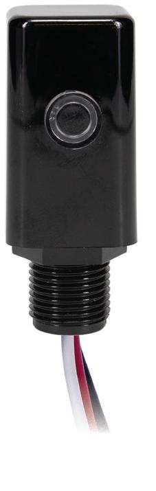
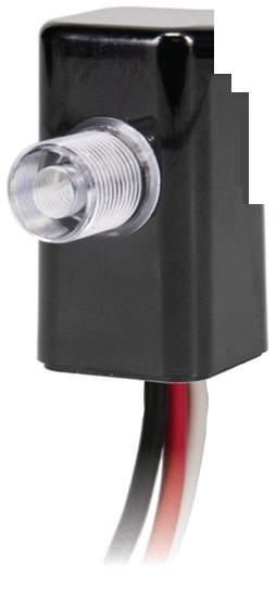
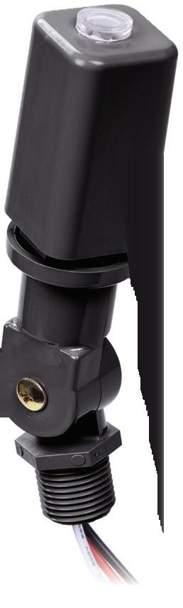
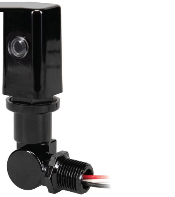
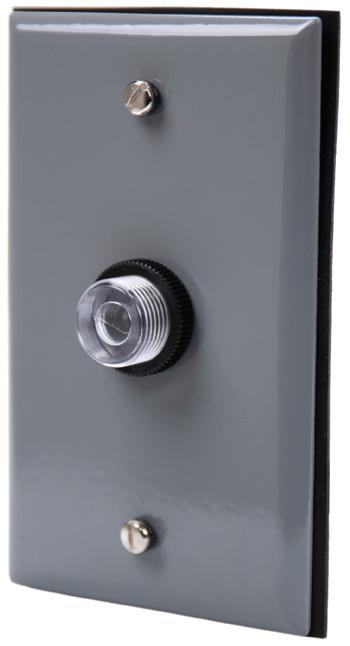
Converting traditional light fixtures to LED provides lasting energy savings and lower operating costs. However, if LED fixtures are paired with thermal photocontrols, that costsavings is quickly lost due to premature failures and unplanned maintenance needs.
Choose high-performance NIGHTFOX Electronic Photocontrols to ensure the long-term success of LED conversion projects. Our new fixed mount electronic photocontrols are designed for LED and can accommodate projects of all budgets and sizes.


Learn more today at


With its exclusive online content, ecmweb.com is a valuable source of industry insight for electrical professionals. Here’s a sample of what you can find on our site right now:
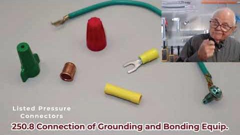
EC&M TECH TALK — METHODS OF GROUNDING AND BONDING
Video Randy Barnett covers some of the most often used NEC rules for making grounding and bonding connections. ecmweb.com/55327337

NFPA 70E: KEY TERMS ELECTRICIANS SHOULD KNOW, PART 1
Safety The content advocates for a shift from superficial safety measures to genuine engagement, encouraging employees and leaders alike to embrace safety as a core value that enhances productivity and well-being. ecmweb.com/55323658

DEBATE OVER NEW YORK’S SCAFFOLD LAW: SAFETY, COSTS, AND LEGAL REFORM
Members Only The current scaffold law imposes strict liability on contractors, developers, and owners regarding fall from heights injuries by workers. ecmweb.com/55325700
Editorial
Editor-in-Chief: Ellen Parson, eparson@endeavorb2b.com
Managing Editor: Ellie Coggins, ecoggins@endeavorb2b.com
Editor: Michael Morris, mmorris@endeavorb2b.com
Art Director: David Eckhart, deckhart@endeavorb2b.com
Consultants and Contributors
NEC Consultant: Mike Holt, mike@mikeholt.com
NEC Consultant: Russ LeBlanc, russ@russleblanc.net
Sales and Marketing
VP/Market Leader - Buildings & Construction: Mike Hellmann, mhellmann@endeavorb2b.com
Regional/Territory Account Manager: David Sevin, dsevin@endeavorb2b.com
Regional/Territory Account Manager: Jay Thompson, jthompson@endeavorb2b.com
Regional/Territory Key Account Manager: Ellyn Fishman, efishman@endeavorb2b.com
Account Manager: Steve Suarez, ssuarez@endeavorb2b.com
Production and Circulation
Production Manager: Josh Troutman, jtroutman@endeavorb2b.com
Ad Services Manager: Deanna O’Byrne, dobyrne@endeavorb2b.com
User Marketing Manager: James Marinaccio, jmarinaccio@endeavorb2b.com
CEO: Chris Ferrell COO: Patrick Rains CDO: Jacquie Niemiec
CMO: Amanda Landsaw CALO: Tracy Kane EVP Building & Construction Group: Chris Perrino VP of Content Strategy: Mike Eby
Electrical Construction & Maintenance (USPS Permit 499-790, ISSN 1082-295X print, ISSN 2771-6384 online) is published monthly by Endeavor Business Media, LLC. 201 N. Main St 5th Floor, Fort Atkinson, WI 53538. Periodicals postage paid at Fort Atkinson, WI, and additional mailing offices. POSTMASTER: Send address changes to Electrical Construction & Maintenance, PO Box 3257, Northbrook, IL 60065-3257. SUBSCRIPTIONS: Publisher reserves the right to reject non-qualified subscriptions. Subscription prices: U.S. ($68.75 year); Canada/Mexico ($ 112.50); All other countries ($162.50). All subscriptions are payable in U.S. funds. Send subscription inquiries to Electrical Construction & Maintenance, PO Box 3257, Northbrook, IL 60065-3257. Customer service can be reached toll-free at 877-382-9187 or at electricalconstmaint@omeda.com for magazine subscription assistance or questions.
Printed in the USA. Copyright 2025 Endeavor Business Media, LLC. All rights reserved. No part of this publication may be reproduced or transmitted in any form or by any means, electronic or mechanical, including photocopies, recordings, or any information storage or retrieval system without permission from the publisher. Endeavor Business Media, LLC does not assume and hereby disclaims any liability to any person or company for any loss or damage caused by errors or omissions in the material herein, regardless of whether such errors result from negligence, accident, or any other cause whatsoever. The views and opinions in the articles herein are not to be taken as official expressions of the publishers, unless so stated. The publishers do not warrant either expressly or by implication, the factual accuracy of the articles herein, nor do they so warrant any views or opinions by the authors of said articles.
Reprints: Contact reprints@endeavorb2b.com to purchase custom reprints or e-prints of articles appearing in this publication.
Photocopies: Authorization to photocopy articles for internal corporate, personal, or instructional use may be obtained from the Copyright Clearance Center (CCC) at (978) 750-8400. Obtain further information at www.copyright.com.
Archives and Microform: This magazine is available for research and retrieval of selected archived articles from leading electronic databases and online search services, including Factiva, LexisNexis, and ProQuest.
Privacy Policy: Your privacy is a priority to us. For a detailed policy statement about privacy and information dissemination practices related to Endeavor Business Media products, please visit our website at www.endeavorbusinessmedia.com.
Please Note: The designations “National Electrical Code,” “NE Code,” and “NEC”

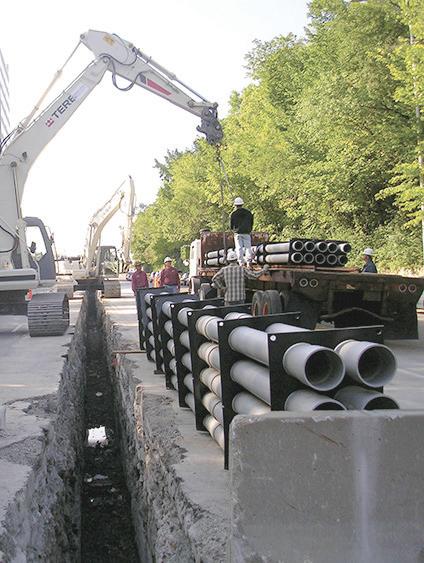
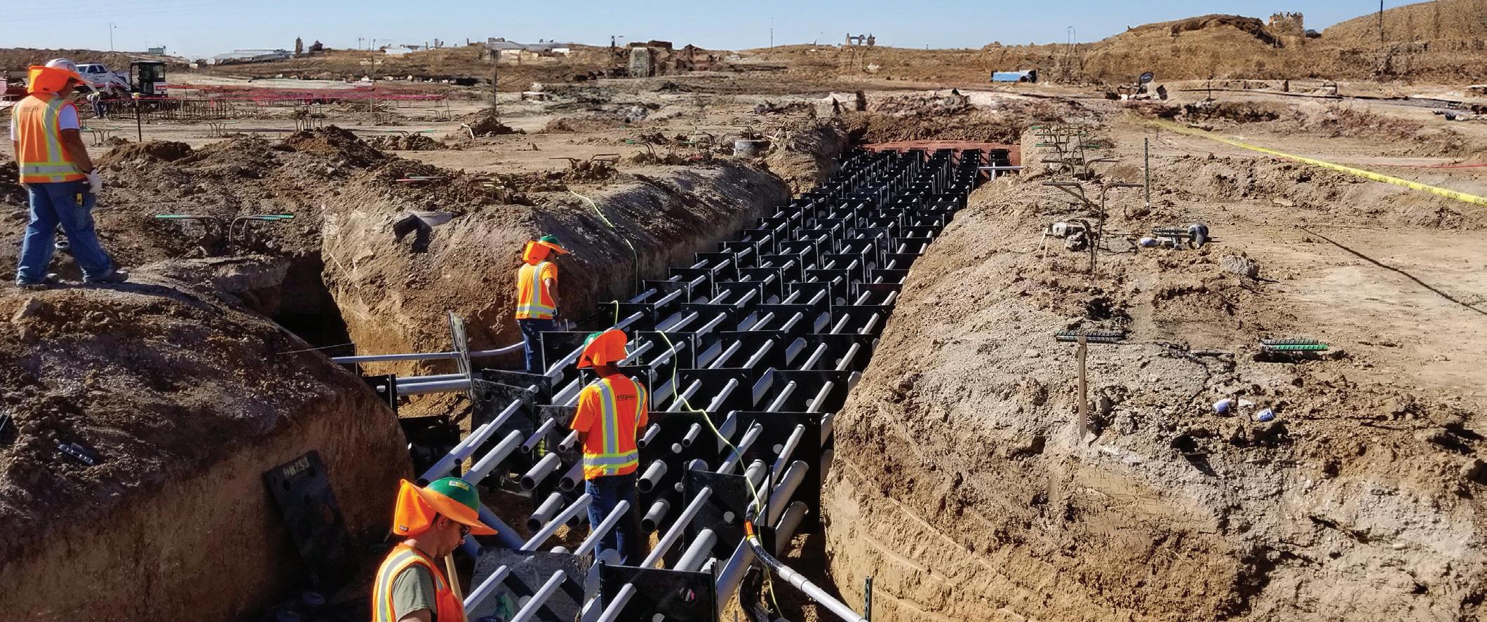
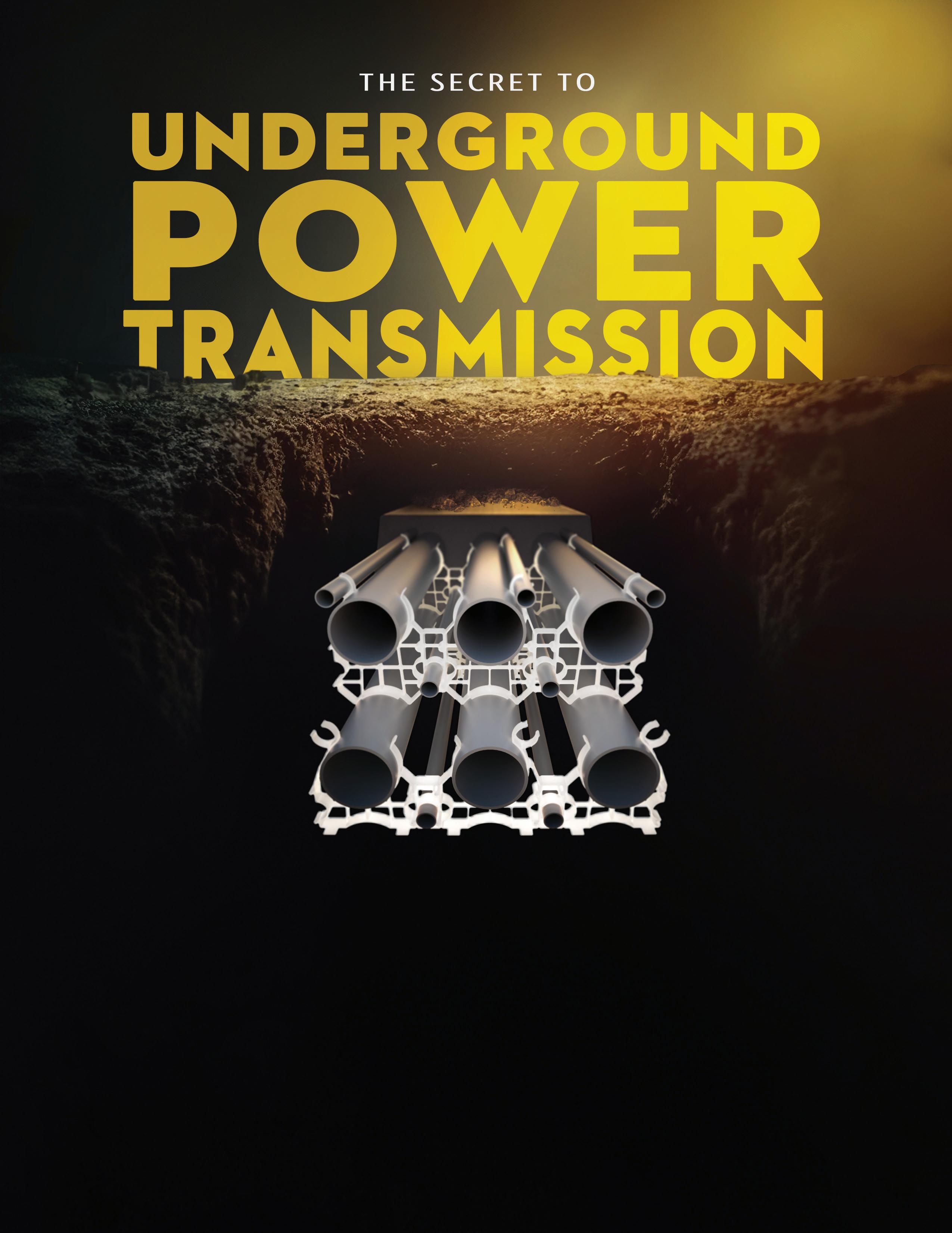
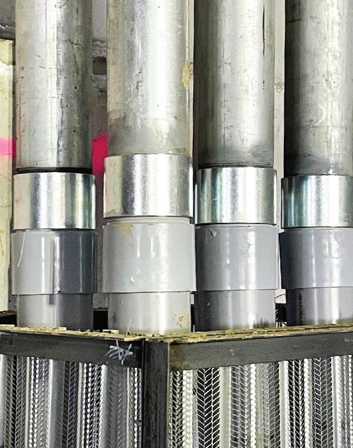
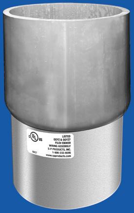
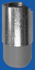
Assemble Conduit Above TrenchNo Workers BelowPrevents Injuries and Deaths. Also Allows Digging a Narrower Trench for Less: Excavation, Concrete, Slurry, Backfill & Shoring.


By Ellen Parson, Editor-in-Chief

Everyone in the electrical industry knows that the National Electrical Code (NEC) is revised and updated on a three-year cycle. As I prepared content for this November issue, it certainly doesn’t feel like three years have passed since the last time we presented the most important revisions to the Code, but here we are again. I have been working on EC&M for decades, so while contemplating yet another update to the most important resource available to the electrical profession, I started wondering how many states and local jurisdictions had adopted the most recent version of the Code since the last time I checked.
Although the NEC is not a federal law, state and local governments have the authority to adopt it into their own legal codes. Therefore, it’s essential for electrical professionals to be cognizant of which versions of the Code are being enforced in the jurisdictions and municipalities in which they work, especially those whose jobs take on a national footprint. To find out how many states were operating under which versions of the NEC, who better to turn to for answers than the publisher of NFPA 70: the National Fire Protection Association (NFPA). Not surprisingly, I found that the 2023 edition is currently the most widely adopted version of the NEC as of press time.
According to the NFPA website, as of October 1, 2025, “20 states have completed their 2023 NEC update process. Seven states currently using the 2020 NEC, two using the 2017 NEC, and one using the 2008 NEC have commenced the process of revising the statute or administrative rule through which the NEC is updated to reference the 2023 edition. One state currently using the 2017 NEC is in the process of updating to the 2020 NEC.” The best way to determine the current Code edition being used in a particular state is to visit NFPA’s website and check the state map and corresponding table at https://www.nfpa.org/educationand-research/electrical/nec-enforcement-maps. Since the 2026 edition of the NEC was just released in August of 2025, no state has initiated their rule-making process to update to the 2026 NEC yet. However, the process of reviewing, implementing, and sometimes amending it will begin over the course of the next several years. In the meantime, no matter what version of the Code you’re working under, it’s critical for electrical professionals everywhere to familiarize themselves with the revisions to each new edition. I know what you may be thinking — if your area won’t be enforcing the 2026 version anytime soon, why take the time and effort to learn it now? Because understanding the key changes today gives you a critical head start tomorrow — helping you anticipate design impacts, update safety procedures, and avoid costly surprises once adoption begins.
To unpack the 2026 NEC, EC&M has once again teamed up with nationally recognized Code expert and longtime EC&M contributor Mike Holt to offer you the key changes made to this latest edition we believe will affect the largest number of readers. Take a look at the online gallery at www.ecmweb.com/55326173 for short summaries of each change. Then, set aside some time to sit down, focus, and fully take in the comprehensive coverage of our cover story, starting on page 32 and offering in-depth analysis and expert commentary on each change. I know it’s a lot to ask in today’s fast-paced world for you to sit down and read a 16-page print article, but trust me, you won’t regret it — you can scan it for changes that most affect your work and save it for reference. You’ll also be able to access the online version plus download a free PDF of the article on our website as well.
With nearly 4,000 public inputs, more than 1,500 first revisions, roughly 1,800 public comments, and close to 900 second revisions, the 2026 NEC represents one of the most significant Code cycles in recent memory. This edition reflects several major forces shaping today’s installations, including electrification, widespread EV adoption, clean-energy infrastructure, modernized building loads, and evolving electrical safety practices. In addition to our online and print editorial coverage, don’t miss the chance to get up close and personal with these important changes. Attend EC&M’s Boston Code Change Conference from January 13-14, presented by Code guru Mike Holt, for a chance to learn about which major NEC changes will impact your work the most. Go to https://www.codechangeconference.com/2026/boston for more information or to register.


Learn how ESA can be used to assess transformer health, detect faults, and improve power quality across various applications, including wind, solar, and industrial settings.
By Howard W. Penrose, MotorDoc ®
Periodic and continuous electrical signature analysis can be used to evaluate the general condition and power quality that affects oil- and dry-type transformers. This article discusses how conditions such as loose connections, resonance, component looseness, and failing electrical components can be detected. Case studies from several applications, including wind power, solar, and industrial dry- and oil-type transformers, are presented.
The purpose of electrical signature analysis (ESA) is to use the magnetic field in the air gap of an electrical machine to evaluate power quality — the condition of the electrical and mechanical components in the electric motor or generator and driven equipment. The analysis is performed using measured voltage and current data with the line frequency acting as the amplitude-modulated carrier frequency. Sample rates, FMAX, bin size, and Nyquist are similar to those of vibration analysis with a Nyquist value of 2 and the data being analyzed in an FFT spectrum in either linear data or decibels. Decibel levels are read down from the peak voltage or current to associated peaks and are presented as -dB (or dB down). Unlike in vibration, where a value such as stator conditions is the number of stator slots times the running speed, ESA is the number of stator slots times the RPM +/- of the line frequency. In the case of electric machines, most conditions (and the forcing
Electrical Testing Education articles are provided by the InterNational Electrical Testing Association (NETA), www. NETAworld.org. NETA was formed in 1972 to establish uniform testing procedures for electrical equipment and systems. Today the association accredits electrical testing companies; certifies electrical testing technicians; publishes the ANSI/NETA Standards for Acceptance Testing, Maintenance Testing, Commissioning, and the Certification of Electrical Test Technicians; and provides training through its annual conferences (PowerTest and EPIC — Electrical Power Innovations Conference) and its expansive library of educational resources.


If you’re an engineer, commercial or industrial facility manager, or electric utility employee concerned about the quality and reliability of power delivery, this e-newsletter (sent out monthly) is for you.
Topics covered include:
• Power quality
• Voltage sags & swells
• Transients
• Harmonics
• Power factor
• Test & measurement techniques
See all of our EC&M e-newsletters at www.ecmweb.com

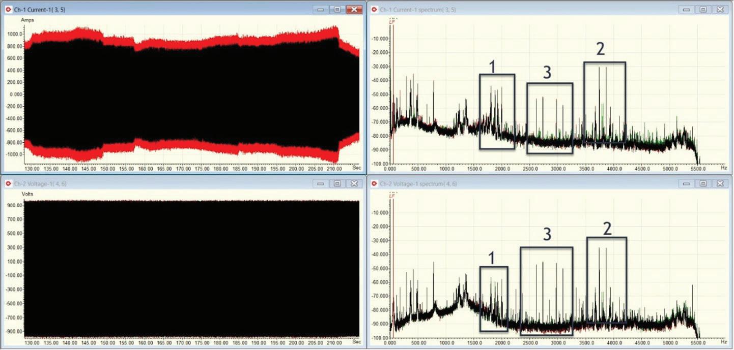
1. Secondary of subtransformer with primarily 5th and 7th harmonics and multiples in voltage and current.
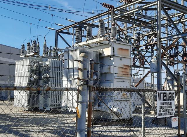
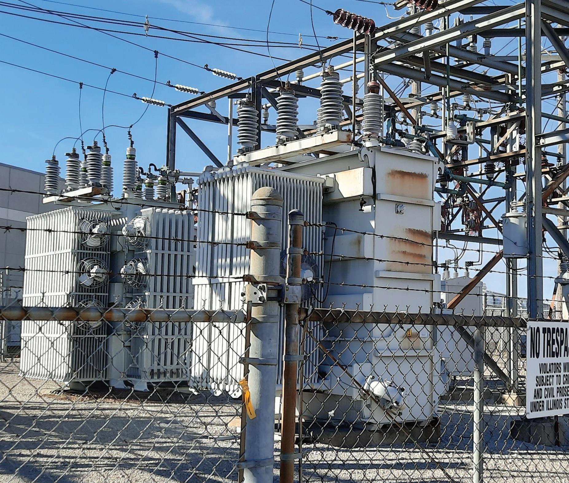
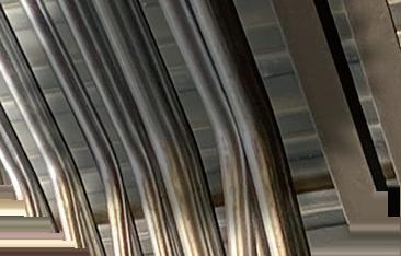
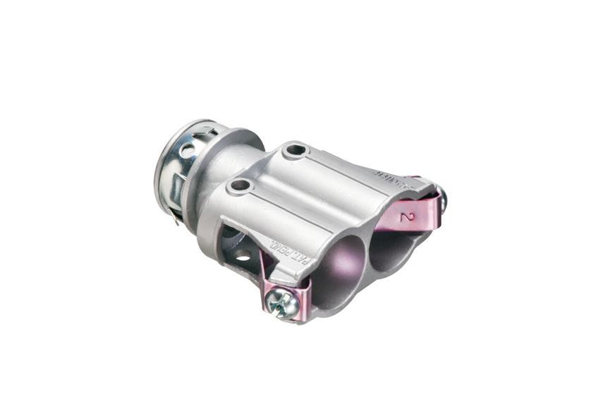
functions associated with them) are interpreted directly from the supplied data. This means that a defect in a bearing, rotor, or stator is explicit, while the use of the technology and measurements of a transformer’s electrical signature are implicit and infer conditions associated with condition and reliability. With transformers, we review phase impedance, power factor, phase balance, harmonics, and variations in the magnetic field between primary and secondary. In oil-filled transformers, the pass-through connections go through
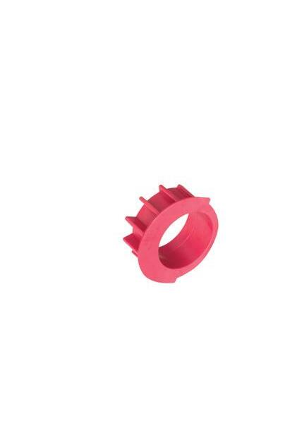
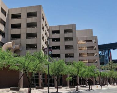
insulated seals referred to as bushings that seal the oil in. These are often oil-filled and hold the external connections away from the transformer frame (Photo 1 on page 10). The fins on the sides are radiators for cooling the transformer oil, which normally relies upon thermal flow. Fans may be applied to extend the operating range of the transformer. Large sealed transformers may also include an expansion tank for excess oil as it expands thermally. There may also be pressurized nitrogen and nitrogen bottles to keep dissolved gases in the transformer
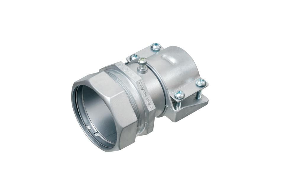


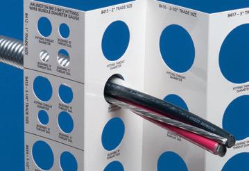
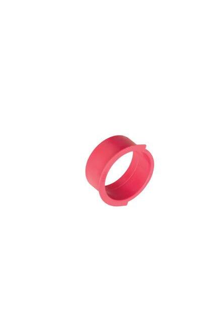
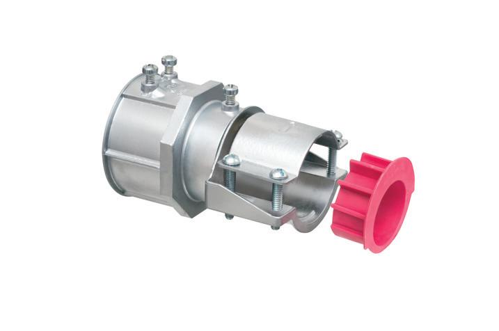
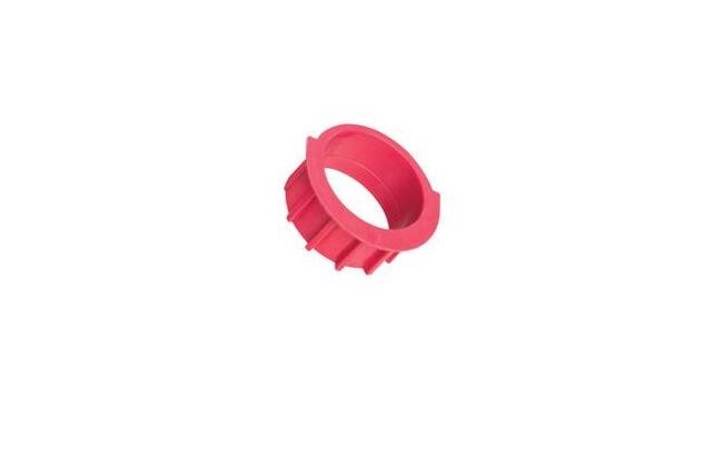
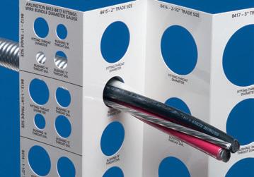
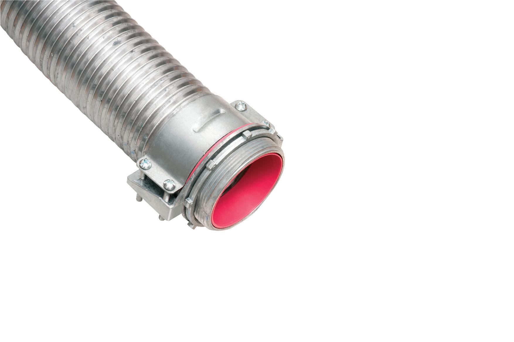
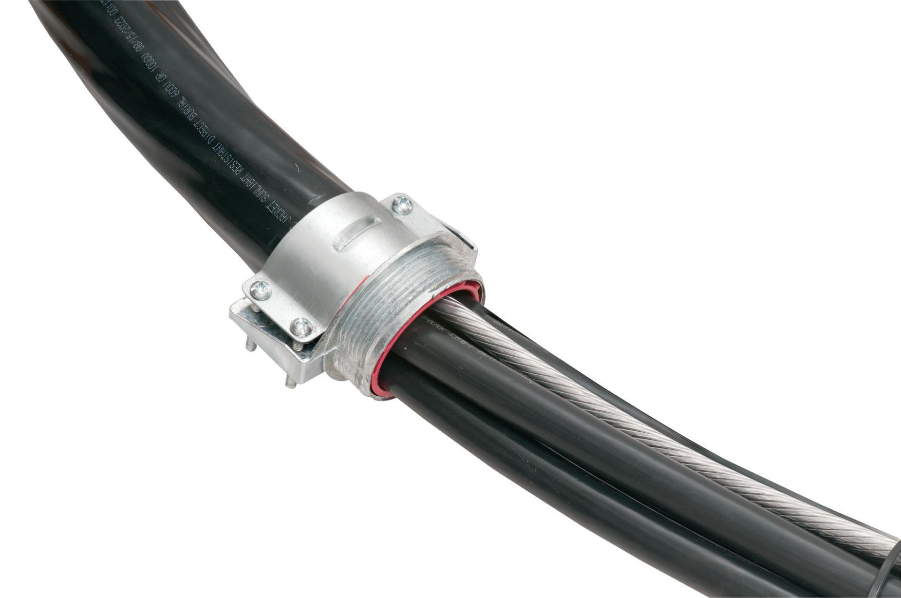
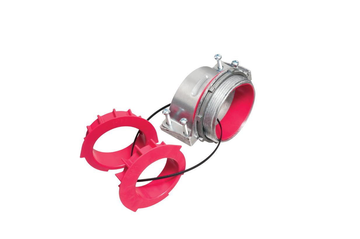
Perfect for data center remote power panel feeds, panels, equipment feeds and EV Chargers in parking garages, Arlington’s Listed CableStop® Transition Fittings deliver the efficient, cost-effective way to transition feeder cables to 1.25", 2.5", 3" and 3.5" EMT, IMC and RMC conduit in protective drops, risers and feeds to panels and equipment. Our new CableStop fittings integrate our patented, versatile and SKU-reducing 8412 series cable fittings, with Arlington conduit fittings, allowing for easy transitions to larger knockout sizes.
Available with set-screw or compression connections into 1.25", 2.5", 3" and 3.5" conduit, they ship with multiple end stop bushings that vary the size of the opening – along with a free template select the right bushing for the cable.


oil and protect the insulation system and oil from water. Transmission and distribution systems, as well as some large substation transformers, may also have auto-taps that adjust for voltage to keep the output within an acceptable range.
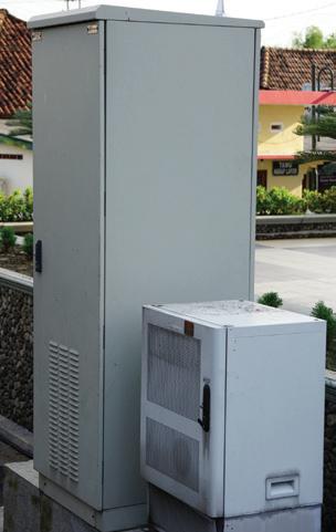
The primary difference between an oil-type and a dry-type transformer is the cooling medium and resulting size. Dry-type transformers (Photo 2 on page 12) use air as the cooling medium. Both transformer types require slightly different maintenance tasks and have slightly different failure modes. In oiltype transformers, the cooling medium can accelerate reliability issues through degradation from soluble gases generated from age, contamination, heat, and operation. Dry-type transformers are subject to contamination and problems with airflow.
Dry and oil transformer types are subject to problems associated with power quality, loose connections, cooling medium issues, and other conditions associated with loads and the environment. Several existing technologies are used for different voltage levels and fault types. These are normally passive or injected technologies, such as turn-to-turn ratio testing, oil analysis, ultrasound, vibration analysis, partial discharge testing, insulation resistance, and others. Many papers and articles associated with using electrical signature analysis and power quality testing are available. This article will focus on the types of issues associated with ESA fault detection in transformers.
Using ESA for transformers provides an additional level of fault detection, especially when used for continuous monitoring. Conditions covered in this include:
• Power quality, including power factor and harmonics
• Core excitation in wind power applications
• Load balancing in solar applications
• 13.8kV to 480V transformer overload due to ground/neutral harmonic content
• Loose connections on the transformer bushing
During an electrical reliability evaluation of a food processing site, it was
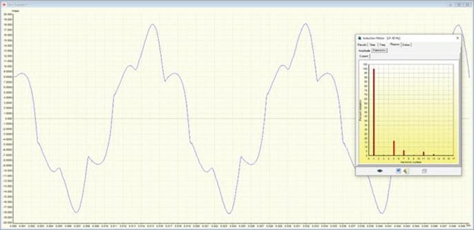
Fig. 2. Ground conductor current waveform for one of the subtransformers. Note: This value should be in milliamps.
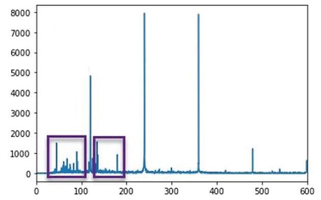

3. Power analysis data based on audio related to transformer sound.
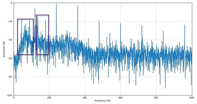
4. Decibel analysis data of transformer audio. 120 Hz and related harmonics are directly related to power factor and harmonic content.
noted that the main transformer supplying the facility had a tinny ring to it. Evaluation of the subtransformers
fed from the main transformer, observation of the main transformer heating on a 34°F day while operating

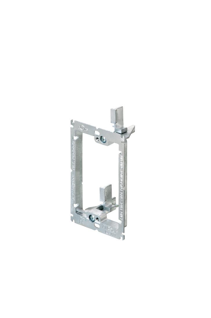

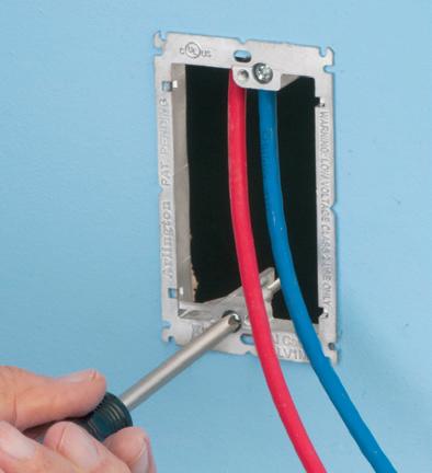
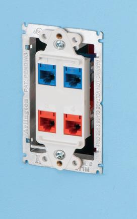
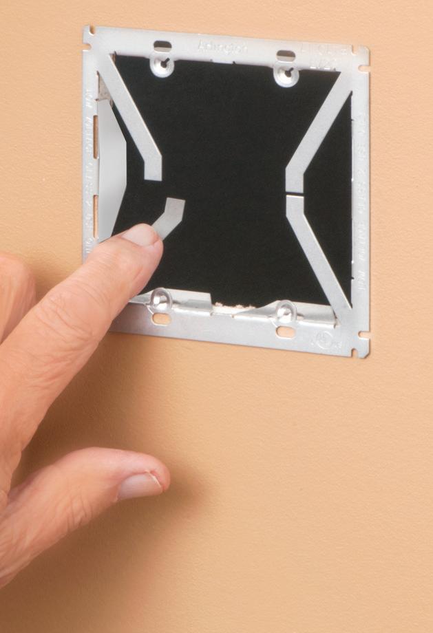

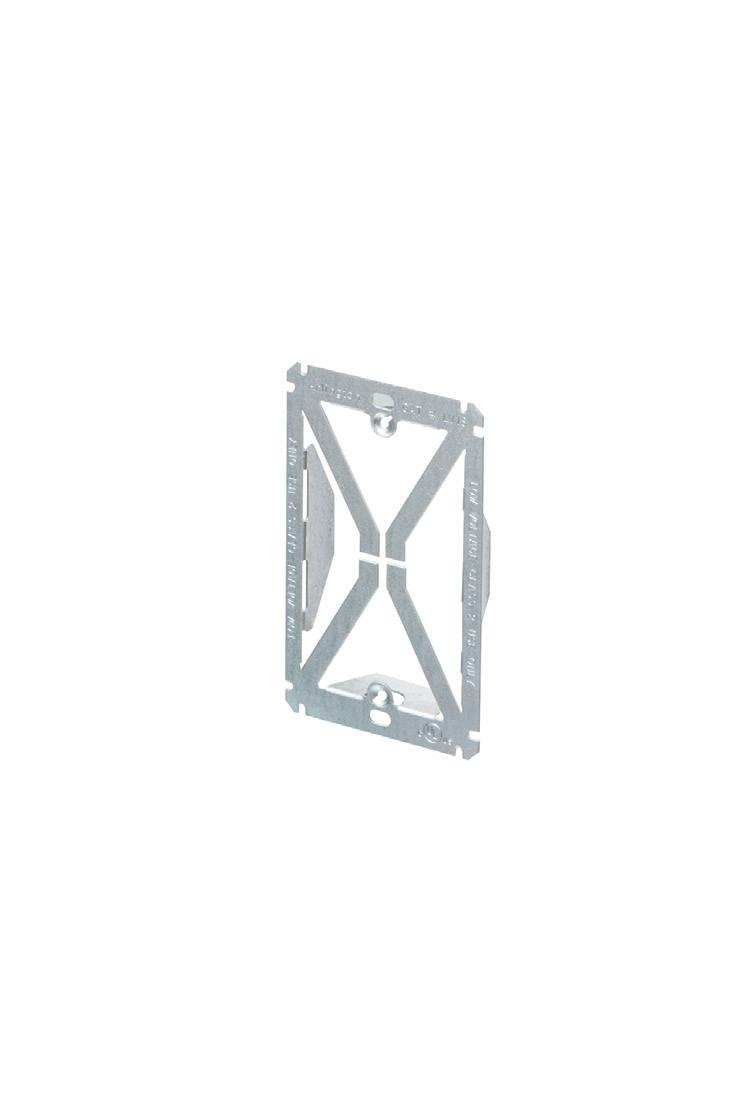
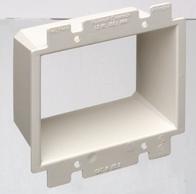
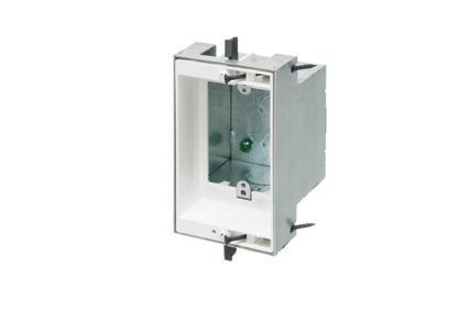
Arlington’s Low Voltage Mounting Brackets are the solution for fast and easy cut-in installation and mounting of Class 2 communications, computer and cable TV wiring and connections.
Introducing METAL low voltage mounting brackets for EXISTING or RETROFIT construction...
LV1M and LV2M COMMERCIAL GRADE
• Extra rigidity and stability where performance and visibility are important or critical
• Threaded holes for easy, fast device installation
• Adjustable bracket for 1/4" to 1" wall board thicknesses
Our LV1S and LV2S PLATED STEEL bracket design, provide excellent stability and secure installation of low voltage devices in 1/4" to 1-1/4" walls - without an electrical box.


at a measured 70% load, and a plant power factor under 0.8 indicated that the main transformer was overloaded, and the harmonic level and power factor were outside of its operating capabilities.
Figure 1 on page 12 shows the voltage and current waveforms at the primary side of one of the subtransformers.

Time-saving non-metallic CableAble® Support Brackets are the ONE BRACKET for support of EMT or flexible metal conduit, power MC and NM cables, and low voltage cables, in commercial or residential work, with plenum or non-plenum ceilings.
Four- and eight-hole CableAble mounts horizontally or vertically to studs or unistrut. And horizontally to all thread and beam clamps.

Lowers total installed cost • Minimizes space required for support –Reduces ceiling congestion • Plenum applications per NEC 300.22(c)


CA8 Eight, 1-1/4" T Bracket
CA8L Eight, 1-1/4” L Bracket CA4 Four, 1-1/4" T Bracket CA4L Four, 1-1/4” L Bracket All styles available in bulk 50 packs. To order, add “X” suffix to item number.
Figure 2 on page 14 shows the current on the grounding conductor between the subtransformer and main transformer. Each of the subtransformers adds to the power factor, harmonic level, and ground/neutral loads at the electric utility feed.
The harmonic content shows up in the power signal and ground path back to the main transformer. Poor power factor adds to core heating and the overall transformer’s effective load. The 70% load quoted from the electric utility is based upon the apparent load and does not include derating and core resonance due to poor power factor and harmonic content.
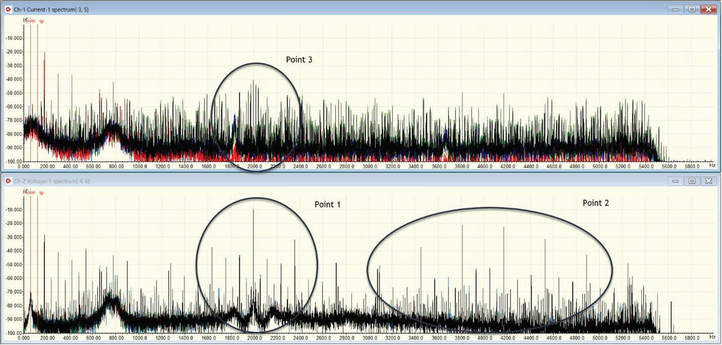
Due to access restrictions, smartphone audio was obtained and processed to show power loss (Fig. 3 on page 14) and decibel patterns (Fig. 4 on page 14). The purple squares in Fig. 6 are related to loose components, and the red arrow points to core vibration due to harmonics and high ground currents. Figure 7 shows the power factor and core vibration (refer to IEEE Std. C57.136-2000, IEEE Guide for Sound Level Abatement and Determination for Liquid-Immersed Power Transformers and Shunt Reactors Rated over 500kVA). The poor power quality conditions will reduce the life of the transformer.
A common problem in the wind industry is overheating transformers due to a combination of factors, including the firing frequency of rotor inverters in doubly fed induction generators (DFIG). The factors that generate this issue are outside the scope of this article. However, the conditions are easily detectable with ESA, including detection of the inverter frequency and a transformer excitation frequency that falls between the first and second inverter harmonic.
The frequencies (Fig. 5 on page 16) generate heating in the transformer core and will generally increase thermal gassing, depending on the dielectric oil, which primarily consists of hydrogen. Thermal and chemical degradation of the insulating materials inside the transformer may result. In dry-type transformers, resonance will also affect connections.
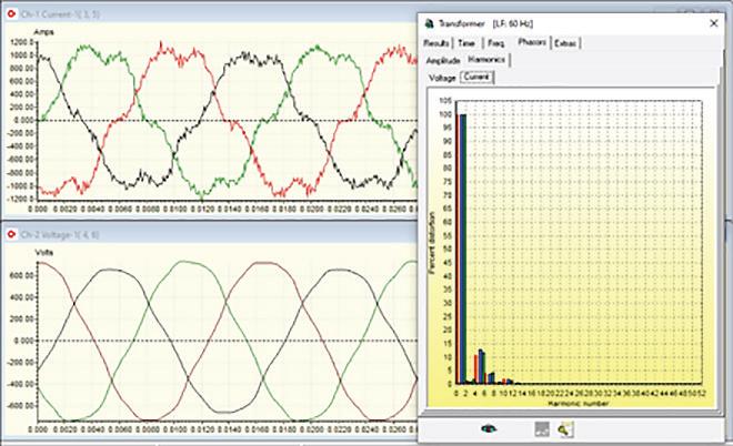
Fig. 6. Current and voltage waveforms before neutral and ground harmonic correction. Note the even and odd harmonics.


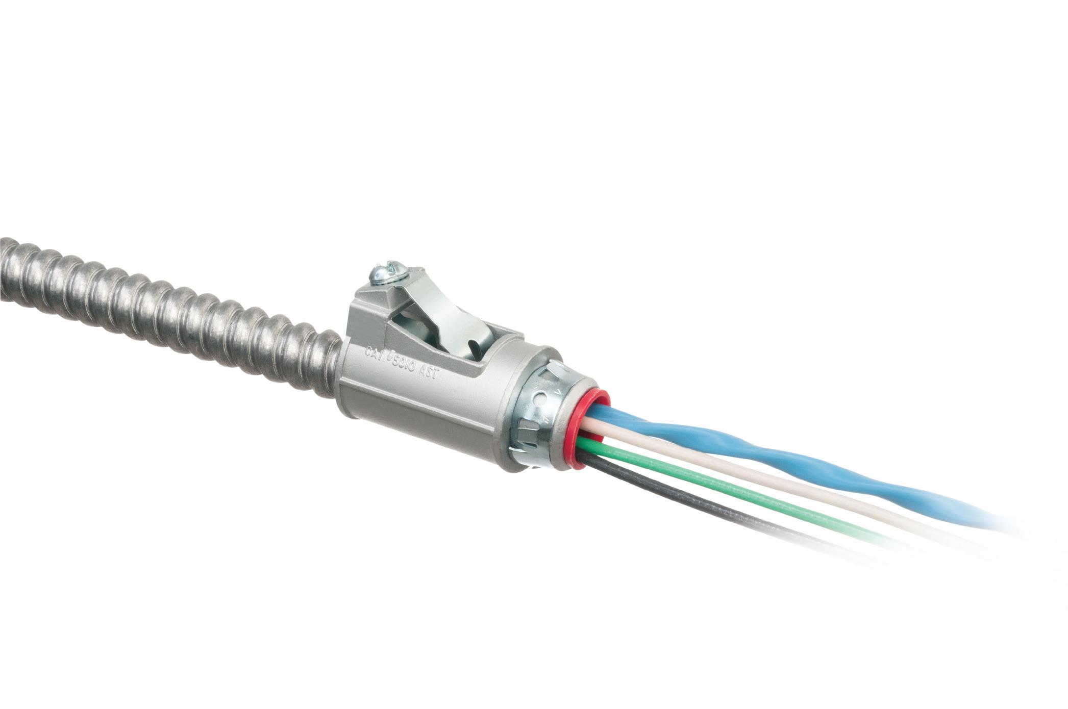
Fig. 7. Current and voltage waveforms after installation of neutral and ground har monic correction.
The ground and neutral feedback to the transformer will generate heating and increase the loading on the transformer in cases where voltage and current are present, in particular where there are harmonics over the fundamental.
Note the changes between Fig. 6 and Fig. 7 — where neutral and ground harmonic correction was implemented. The noise in the current waveform decreases, and the even harmonics are eliminated due to a reduction in load on the transformer core. The comparison is at a similar load current.
Loose connections ( Fig. 8 on page 20) are found through a combination of impedance unbalance; even harmonics will often be present. The impedance unbalance distinguishes between harmonic loading and the loose connection.
ESA is an excellent tool for direct or incidental detection of major defects in transformers by evaluating the power quality, phase impedance, and impact of loads. In these examples, we have detected loose connections,
17SAVE seconds
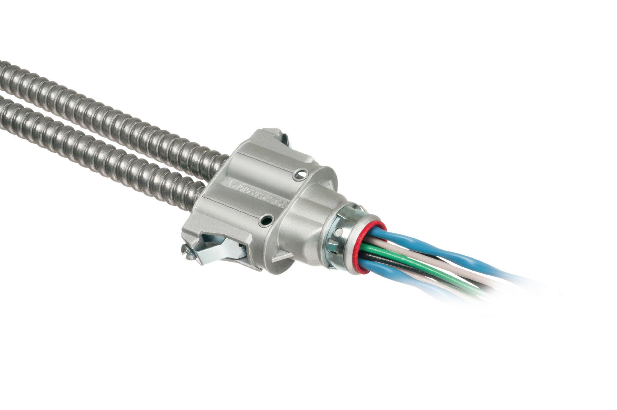
Fully assembled, SNAP2IT® fittings handle the widest variety of MC cable AND THE NEW MC-PCS cables.

Compared to fittings with a locknut and screw, you can’t beat these snap in connectors for time-savings!


LISTED SNAP2IT ® CONNECTORS FOR NEW MC-PCS CABLE ...lighting & low voltage circuits in the same cable


• Fits widest range and variety of MC cable 14/2 to 3/3
AC, MC, HCF, MC continuous corrugated aluminum cable and MCI-A cables (steel and aluminum)...including the new MC-PCS cable that combines power and low voltage in the same MC cable
ANY Snap2It Connectors LISTED for MC cable are also LISTED for MC-PCS cable! These products offer the greatest time-savings.
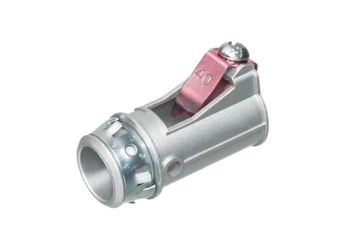
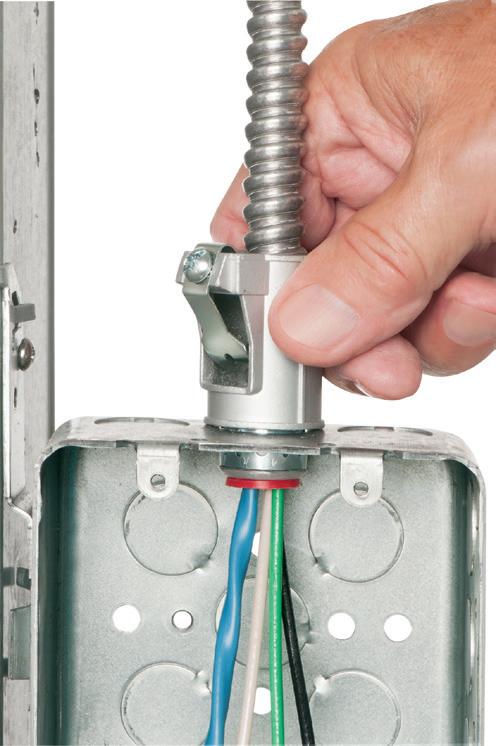
• Fast, secure snap-on installation
• Easy to remove, reusable connector From cable Loosen screw on top. Remove connector from cable. From box Slip screwdriver under notch in Snap-Tite® Remove connector.
overloading, neutral and ground impacts, power factor problems, and a few others. When used as part of
continuous monitoring, these conditions can be found early enough to mitigate the defects.
Howard W. Penrose, PhD, CMRP, CEM®, is president of MotorDoc® LLC, a veteranowned small business.


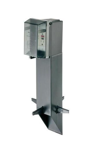
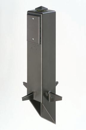
Arlington’s Gard-N-Post® enclosures and supports offer the attractive, safe, and easy way to install a light fixture and/or one or two devices outdoors!

• Non-metallic, heavy-duty UV rated plastic
• Damage resistant
• No chipping... 4 permanent colors
• GARD-N-POST... a variety of styles, 9" to 73" tall


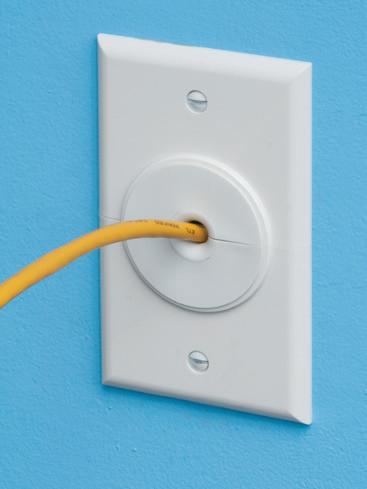
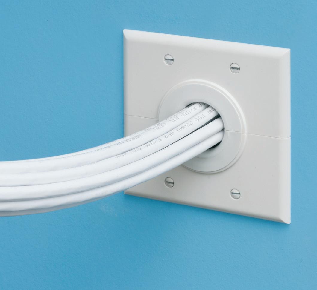
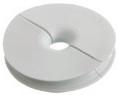
Arlington’s non-metallic Split Wall Plates provide a simple and effective way to accommodate pre-connectorized low voltage cable(s) of varying size and quantity or pre-existing low voltage cables.
Multiple split grommets are provided with our single- and two-gang wall plates for increased versatility in effectively sizing and covering the hole/opening.
Use as shipped, or with one of the supplied bushings to alter the size of the opening.
• Single-gang CESP1 w/ 1-1/2" opening, bushings for .312" • .500" • 1" openings bushings for .750" • 1.250" openings


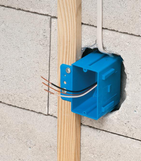


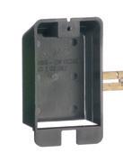
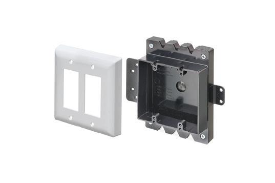
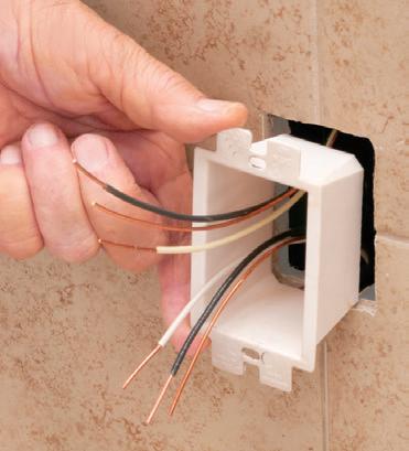
Arlington’s new Furred Wall Box® kit makes challenging outlet box installations fast and easy!
Versatile mounting options Our high strength FSB series outlet box kits are designed for use with existing 1x2 drywall furring strips – but can also be mounted directly to a concrete block wall between furring strips. Place the box or outlet where it’s needed.

Integral cable securement – No pullout! Accommodates GFCI and USB receptacles. Convenient kits simplify ordering of FSB1 and FSB2.
High-strength No breakage in cold weather
Integral Mounting Flanges
NEW FSB12 * FSB22
ADD OUR BOX EXTENDERS to BROADEN APPLICATION and USE

Furring strip flange Mounting Bracket
Base

One-gang FSB12
Block wall flange Mounting
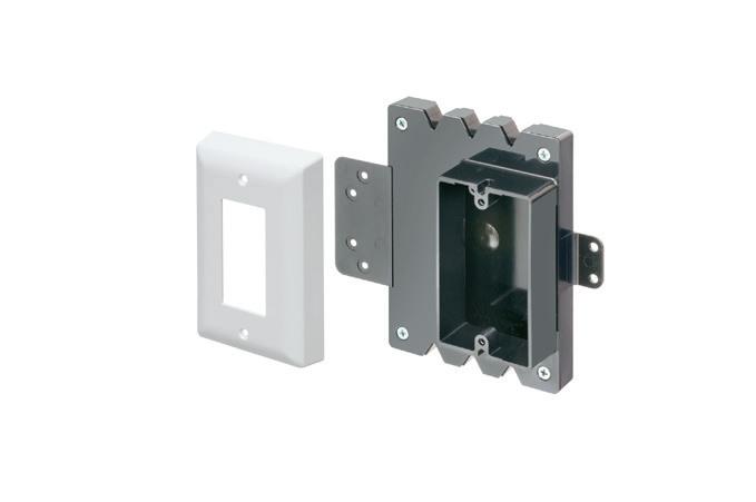
Our NEW Low Profile single and two-gang Furred Wall Box® base assemblies have 1/2" raised ring for use with standard wall plates.
They combine with Arlington’s Box Extenders to deliver installation solutions for wall thicknesses from 1/2" to 1-1/2" and varying device depths
• Integral cable securement – No pullout!
• For standard and GFCI devicesUses standard wall plates
• Single gang FSB12 - 17.0 cu. in. Two-gang FSB22 - 20.5 cu. in.


Add our BOX EXTENDERS for these specific conditions...
1 if Total Wall Layer Thickness is GREATER than 1/2" (up to 1-1/2") Add BE1 or BE2

if Using a Deep Depth Device with 1/2" Wall Thickness Add BES1 or BES2

or Dimmer

By Eddie Guidry, Fluor Enterprises
Proper torque and compression are critical for safe and effective electrical connections.
Interference or modifications to the connections — especially from paint, lubricants, or other coatings — can compromise conductivity, increase impedance of the connection, and/or create unwanted conductive paths, and violate product certification standards.
Do not apply any of the following substances to electrical connections or terminations unless explicitly approved by the equipment manufacturer:
• Liquid or spray paints (i.e., enamel, epoxy, varnish, insulating compounds)
• Lubricating sprays or substances (oils, grease, silicone-based compounds, etc.)
• PVC spray or patching compounds
• Pipe dope, putty, or tape on threaded metal conduit or gland connectors
These materials can:
• Create faults by creating unintended conductive paths.
• Insulate connections, reducing or preventing electrical current.
• Invalidate product certifications, leading to product and code compliance issues.
This guidance applies to all electrical connections, including:
• Mechanical terminals and bolted connections
• Irreversible compression lugs
• Threaded conduit and fittings

• Cable glands and threaded enclosures
• Grounding/earthing connections
There are situations where you can use coatings.
• Exothermic welds Finished exothermic welds are not typically susceptible to liquid or spray paint ingress; however, caution should be used due to possible deleterious effects of unapproved, untested paint on the weld.
• Metal conduit threads Section 300.6(A) of the 2023 NEC permits approved conductive, metal-to-metal anti-corrosion compounds such as Thomas and Betts KOPR-SHIELD® and
Eaton Crouse-Hinds STL8 and HTL4 conductive thread lubricants.
• Zinc-rich conductive coatings (often referred to erroneously as “cold galvanizing”) may be permitted where identified and approved for the purpose.
For more information on zincrich coatings, see the American Galvanizers Association website (https://galvanizeit.org/corrosion/ corrosion-protection/zinc-coatings/ zinc-rich-paint).
Don’t forget to follow these recommendations when it comes to painting or coating electrical connections.
• Always follow manufacturer instructions and product certifications.
• Never assume a coating is safe for electrical use — verify before applying.
• Treat grounding connections with the same caution as ungrounded or intentionally grounded phase conductors.
• Consult the product manufacturer if unsure.
Only equipment manufacturers can specify or approve coatings on electrical terminations. Unapproved applications by the manufacturer can lead to equipment failure, safety hazards, and regulatory violations.
Eddie Guidry is a Senior Fellow with Fluor Enterprises, Inc., Sugar Land, Texas. He can be reached at eddie.guidry@fluor.com.

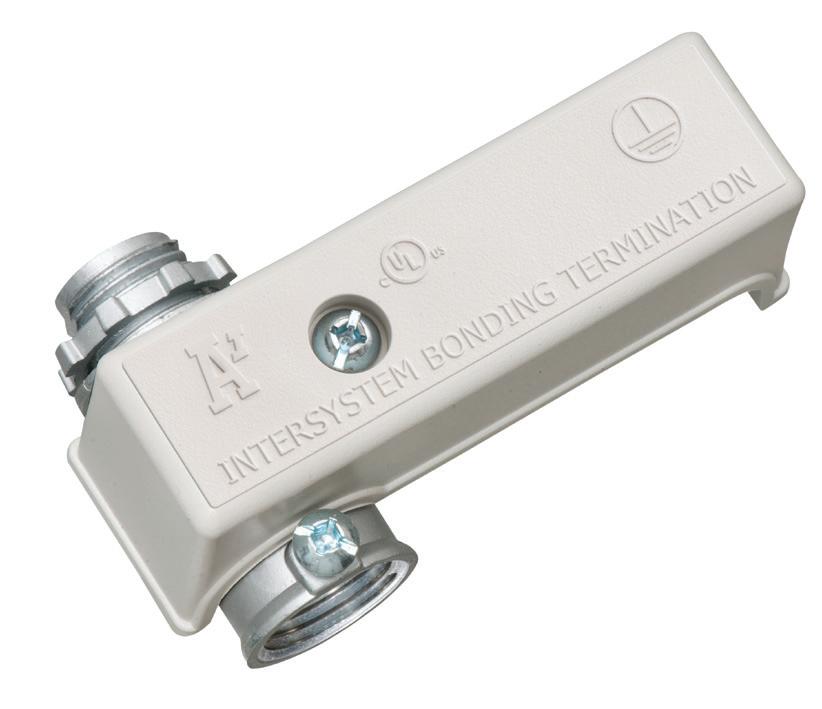


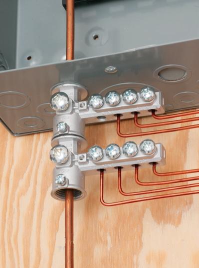
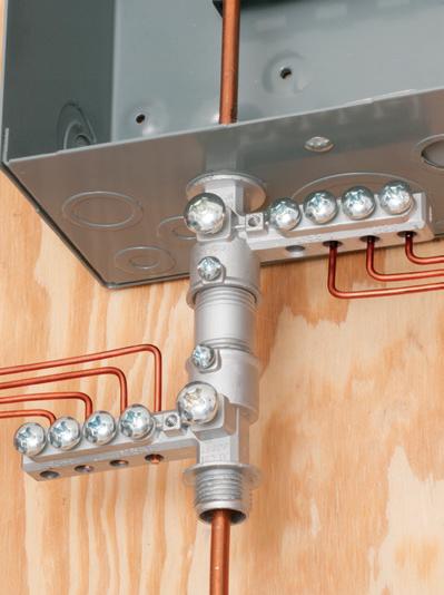
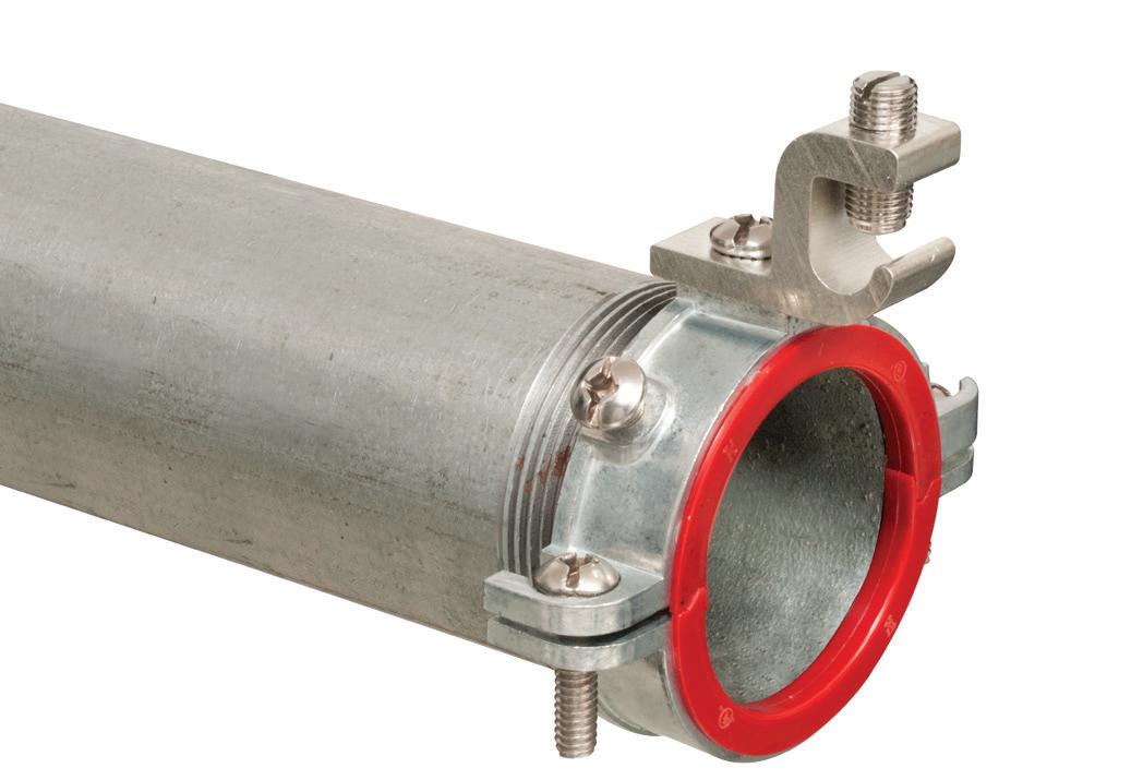
Arlington’s heavy-duty Grounding Bridges provide reliable intersystem bonding between power and communication grounding systems. And handle multiple hookups of communications systems: telephone, CATV and satellite.
Our new GB5T comes with a Combination Threaded and Set-Screw hub for Threaded Rigid – or EMT Conduit.
Arlington’s zinc and bronze grounding bridges...
• Four termination points; more than required by the NEC
• Meet 2020 NEC bonding requirements for 250.94
• Fast, simple installation indoors or outside
• Textured, paintable plastic cover (except GB5NC)


• Easy access for inspections


While working in an electrically safe work condition is important, there are times when working hot is necessary, so be sure to follow NFPA 70E Art. 130 requirements.
By Mark Lamendola, Electrical Consultant
Ideally, you will always put an electrical system or electrical equipment in an “electrically safe condition” (de-energized) before performing work on it. But doing so isn’t always possible or practical, so sometimes you must “work it hot.”
If you’re tasked with working hot, determine whether the reason aligns with the four exemptions found in NFPA 70E Sec. 130.2(C), such as testing. If not, don’t work it hot. You aren’t doing anybody any favors if unnecessarily working hot results in an unplanned shutdown, which is far more costly than a planned shutdown.
If the equipment isn’t energized, you have no risk of electric shock, arc flash, or arc blast. You also have no risk of damaging equipment due to inadvertently shorting two phases. There’s no risk of adverse operation, which can harm people, the environment, or other equipment. If equipment is energized, then you have may have all of these risks. By following the requirements of Art. 130, you can reduce both the likelihood and severity of these risks.
At 15 pages long, Art. 130 isn’t something you can glance at and understand. It takes some study. This overview will help your study of Art. 130 be more effective, or it may deepen your understanding if you’ve already studied it.
These four requirements apply to working hot:
If the system is under 50V, the electric shock and arc flash risks aren’t there, so following Art. 130 isn’t warranted. But you should still follow the standard precautions for protecting that equipment from human error and for preventing adverse operation.
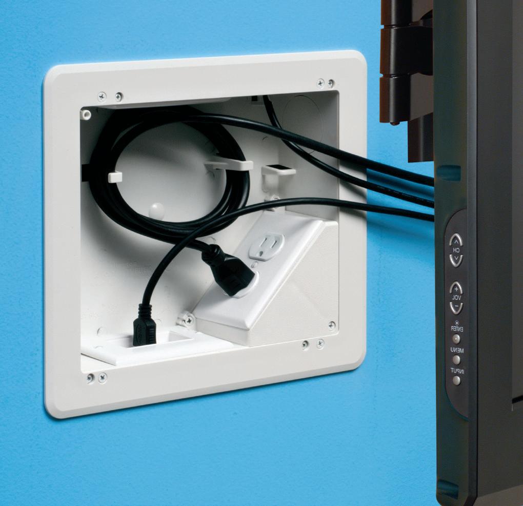
Arlington’s 8X10 TV Box® with a Plastic or Steel Box offers the ultimate in versatility for installing TVs in new and retrofit projects. There's more room in the box for wires and it installs horizontally or vertically to properly position low voltage connections behind the TV.
• Ideal for home theater systems: multiple connections for sound systems, satellite TV, CATV, DVRs
• Brackets for neater cables, with a 1-1/2" knockout for ENT and other low voltage wiring
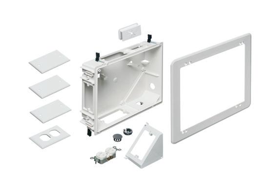

• Box mounts to stud in new work; for retrofit, mounting wing screws secure


The box adjusts to fit wall thicknesses from 1/4" to 1-1/2". Mounting wing screws hold it securely in place.
• 2-Hour
• Low voltage side has a combo 1/2" and 3/4" KO for raceway
• Includes NM cable connector (power side)

Only qualified persons are allowed

This twice-a-month e-newsletter delivers the latest trends and information on electrical safety, reports on specific accidents in the field, and provides tutorials and evergreen safety content that can be used for reference and training.
Topics covered include:
• Best practices for safely working on electrical equipment
• Accidents and investigations
• Arc flash
• PPE
• Shock and electrocution
• Fire and security
• Safety audits
See all of our EC&M e-newsletters at www.ecmweb.com
An electrical work permit must be completed. This is the first of three core strategies [Sec. 130.2].
An electric shock risk assessment must be performed. This is the second core strategy [Sec. 130.4].
An arc flash risk assessment must be performed. This is the third core strategy [Sec. 130.5].
Additionally:
PPE is covered in Sec. 130.7. This is highly detailed and makes extensive use of tables. When applying Art. 130, you may spend a lot of time determining what PPE is appropriate for that particular work.
“Other precautions” are covered in Sec. 130.8. This covers such things as illumination, scope changes, and blind reaching.
• Work within certain specified clearances (including overhead lines) is covered in Sec. 130.9.
• Underground lines are covered in Sec. 130.10.
• Cutting and drilling are covered in Sec. 130.11. The key concept is to identify potential energy sources before drilling or cutting. Finding an energized cable with your power drill may prove to be a bit too exciting, to say the least.
An energized work permit is required when the work is performed on an energized circuit [Sec. 130.2(A)] that isn’t exempted in Sec. 130.2(C).
Because the employee fills out the permit and the employer is the one managing the program under which the permit is issued, many people believe the employee is applying for permission to do the work. A better way to think about it is the employee is giving the employer permission to have the work done. This second perspective prioritizes safety over job completion. Instead of standing in the way of work, the permit allows work to proceed (if its conditions are satisfied).
You’ll find the nine elements of a work permit listed in 130.2(B)(1) through (9). For example, description of the work to be performed and results of the arc flash assessment.
This assessment has three goals:
1. Identify electric shock hazards.
2. Estimate the likelihood of injury or damage, and estimate the potential severity. Take into account the equipment design, operating conditions, and condition of maintenance.
3. Determine if you need additional protective measures. Take into account the voltage, the boundary requirements, and the recommended (by NFPA 70E) protective equipment.
In doing this assessment, you must document what you find and conclude [130.4(D)] and determine the limited approach boundary [130.4(F)] and the restricted approach boundary [130.4(G)].
The limited approach boundary is the closest to the equipment that an unqualified person can get, unless the specific circumstances described here are met. Consider marking this boundary with yellow tape.
The restricted approach boundary is for qualified people. They can’t take any conductive object closer to the exposed energized conductors or circuit parts than this boundary. How do you know where it is? You use Table 130.4(E)(a) and Table 130.4(E)(b). This boundary gets “erased” if the qualified person meets either of the two conditions stated in Sec. 130.4(G). For example, he is insulated or guarded from the energized conductors or circuits. Consider marking this boundary with red tape.
This assessment has the same three goals as the shock risk one, except it’s for arc flash risk. The same parameters of what to account for apply, including the requirement to document everything [Sec. 130.5(D)]. As with the arc flash risk assessment, if additional protection measures are required, you must select and implement per the hierarchy of risk control identified in Sec. 110.3(H)(3).
If those additional measures include PPE, you must determine three things:
1. Appropriate safety-related work practices.
2. The arc flash boundary. This is the distance at which the incident energy equals 1.2 calories per square meter [Sec. 130.5(E)(1)], and you can use the

Side connections lock single gang FLBC8500 boxes together
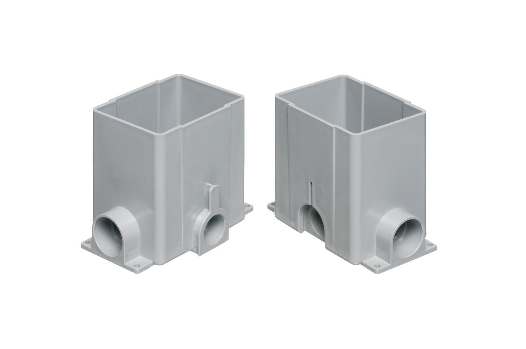
Single gang box
(3) FLBC8500 boxes
(1) FLBC8530BL Black PLASTIC cover/frame kit


Lock two boxes together for a two-gang box. Add another for three-gang!
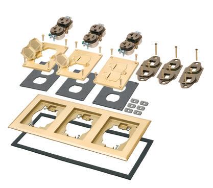
Here’s the easy way to add receptacles in a commercial concrete pour. Lock single gangable boxes together to build a two- or three-gang floor box!
Then add the UL LISTED single, two- or three-gang Cover/Frame kit, with devices included.
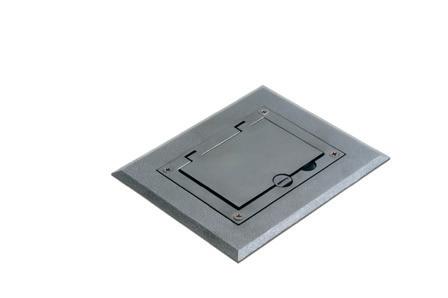
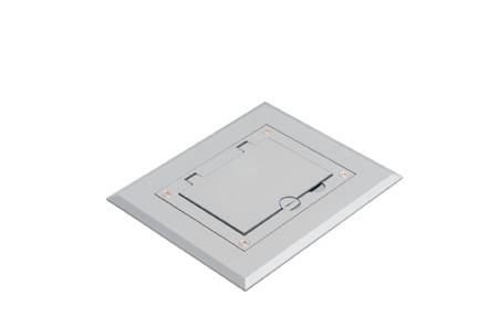
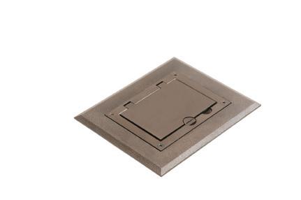
• PLASTIC in Black, Brown, Gray, Light Almond, Caramel...
• DIECAST ZINC with a Brass or Nickel finish... Furniture feed inserts also available with brass or nickel finish
• PLATED, PLASTIC or POWDER-COATED with Flip Lids
Fast, easy cover installation. Installs with hinge on either side.
incident energy analysis method [Sec. 130.5(G)] to determine this.

This weekly e-newsletter offers subscribers a unique and inside view into the most important trends, technologies, and developments taking place within the electrical industry.
Topics covered include:
• EC&M videos & podcasts
• Market forecasts and analysis
• Code Quiz of the Week
• Online-only feature articles
• Late-breaking industry news
See all of our EC&M e-newsletters at www.ecmweb.com
The PPE to be used within the arc flash boundary.
Table 130.5(C) is helpful in determining how likely an arc flash event is. This table is a set of four groupings of tasks: Any operating condition no likelihood of occurrence.
Any operating condition occurrence is likely.
Normal operating condition no likelihood of occurrence (only one task listed: operation of a circuit breaker, switch, contactor, or starter).
Abnormal operating condition occurrence is likely.
This table has extensive footnotes, plus six Informational Notes.
The assessment is clearly a lot of work. The good news is it can be done once for a given piece of equipment. Then a label meeting the requirements of 130.5(H) can be affixed to that equipment. The method of calculating and the data to support the calculation must be documented.
Make sure you examine this documentation, rather than merely trusting the label. To err is human; to suffer an arc flash will truly ruin your day.
The label must be reviewed for accuracy at least once every five years. If any changes in the equipment render the label inaccurate, the label must be updated (it is best to remove or cover the label if it is not current). The equipment owner is responsible for maintaining these labels and the associated documentation.
Section 130.7 comprises one-third of Art. 130. Most of it addresses PPE, but it includes less than a page that deals with insulated tools, ropes, barriers, and so forth [Sec. 130.7(D)]
Before determining which PPE is appropriate, go back to the hierarchy of risk control methods [Sec. 110.2(I)(3)]. There are six, and PPE is dead last. It’s the final safety net, not the first line of defense.
Article 130 contains seven tables for PPE, and another for other types of protection:
1. Table 130.5(C). Arc-rated clothing and other PPE if you use the incident energy method.
2. Table 130.7(C)(7)(a). Maximum voltages for rubber gloves.
3. Table 130.7(C)(7)(b). Maximum test intervals for rubber gloves.
4. Informational Note Table 130.7(C) (14). Standards for PPE.
5. Table 130.7(C)(15)(a). Arc flash PPE categories, AC systems.
6. Table 130.7(C)(15)(b). Arc flash PPE categories, DC systems.
7. Table 130.7(C)(15)(c). PPE.
8. Table 130.7(E). Other protective equipment.
Three key considerations:
1. Employees must use protective equipment that is designed and constructed for the specific part of the body to be protected [Sec. 130.7(A)].
2. Requirements for specific body parts are in Sec. 130.7(C)(3) through (8).
3. All of this equipment must be properly stored and cared for and visually inspected before each use [Sec. 130.7(B)].
One reason often invoked for unnecessarily working hot is it saves time. But that idea is pure fiction. Unless exempted by Sec. 130.2(C), working hot requires conducting two hazard assessments and a PPE assessment plus filling out an energized work permit. You can skip all of that by simply de-energizing the applicable circuits.
Working hot also involves the risk of an unplanned shutdown due to inadvertently triggering some interlock or protective device, adverse operation of equipment, shock to personnel, arc flash, and arc blast. Production management would rather schedule a shutdown than bear the cost and inconvenience of an unscheduled one. And nobody wants a lethal incident.
Working hot so you can get away with not performing a lockout/tagout is a fool’s game. Working hot entails more preparation time, higher preparation costs, and higher risk of high-severity occurrences. So working hot not lockout/tagout is what you want to try to avoid. If you can’t avoid it, then implement the NFPA 70E Art. 130 requirements.
Mark Lamendola is an electrical consultant bases in Merriam, Kan. He can be reached at mark@mindconnection.com.
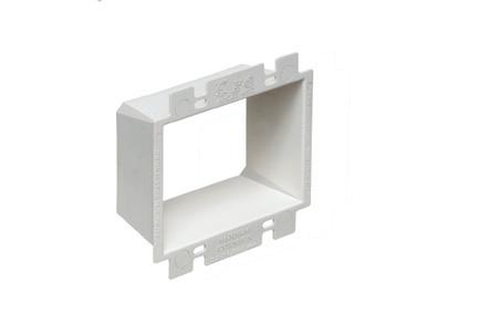
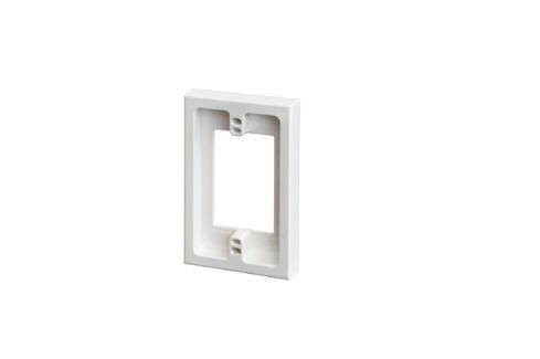
Arlington’s variety of cULus Listed Box Extenders extend set back electrical boxes up to 1-1/2".
Made of heavy-duty, 105°C continuous use 94V0 rated, flame retardant plastic, they level and support wiring devices, while protecting wires against damage and stripping.
Choose the one that’s right for you!
BE1, BE2, BE3, BE4...Single-, two-, three- and four-gang, and BE1R for round or octagonal boxes...
Box Extenders


device support in oversized or mis-cut wall openings, available in single-, two-, three- and four-gang, (patented BE1X, BE2X, BE3X, BE4X.)
Our new heavy duty, COMMERCIAL-GRADE steel support plate! As shipped, single and two-gang BE1XLS and BE2XLS work with maxi cover plates, but they’re and standard plates. Convenient. Saves time. Great for poorly cut drywall.
For all standard devices, switches and GFCIs, our box extenders comply with NEC Article 314.20 for set back boxes.


Breaking down the key revisions and updates every electrical professional needs to know for this Code cycle
By Mike Holt, NEC Consultant
The 2026 National Electrical Code (NEC) marks another year of significant evolution for the electrical industry. With 3,933 public inputs, 1,507 first revisions, 1,800 public comments, 894 second revisions,

and 63 certified amending motions, this latest edition of the Code brings substantial reorganizations, new Articles, and dozens of additional Sections designed to improve clarity and usability. Why do these changes matter? For electrical professionals who are expected to know the NEC inside and out, it’s


important to realize these changes are more than merely administrative. They mirror broader trends shaping the industry, including a continued emphasis on safety, the integration of sustainable technologies, and the adoption of forward-looking practices. For example, expanded GFCI protection requirements underscore the ongoing focus on reducing electric shock hazards, while other changes reflect the growing role of electric vehicles, limited-energy systems, and high-voltage installations in today’s electrical landscape. By embracing these updates, electrical professionals can maintain the highest standards of safety while positioning themselves to meet tomorrow’s technical demands.
Before we dive into the Top 25 changes to the 2026 NEC, there are several global updates worth noting. The term “overcurrent protective device” was replaced with the acronym “OCPD,” reducing repetitive text while standardizing terminology. The term “overcurrent device” was also updated to overcurrent protective device (OCPD). Similarly, the designation “AC” was added to rules that only apply to alternating-current

circuits, clarifying that these require ments do not extend to DC systems.
Many Articles in the 2026 NEC are either new, relocated, or deleted. For specifics on the revisions in these areas, see the Sidebars (New, Relocated, or Renamed Articles on page 52; LimitedEnergy Systems Articles on page 55; and New Articles Over 1,000VAC or 1,500VDC on page 56).


The 2026 NEC also previews structural revisions anticipated for the 2029 edi tion. Informative Annex L provides a clear picture of proposed structural changes and highlights updates made during the 2026 cycle. NFPA has cre ated a dedicated webpage (https://www. nfpa.org/en/education-and-research/ electrical/reorganization-of-thenational-electrical-code) to outline the impact of these revisions and provide a platform for public feedback.
As you read through the analysis on each of the following changes, please note that the blue underlined text is NEW to the Code. Although it is slightly reworded or shortened from the actual text shown in the NEC, it’s a good representation of the intent of the real rule change.


CHANGE #1
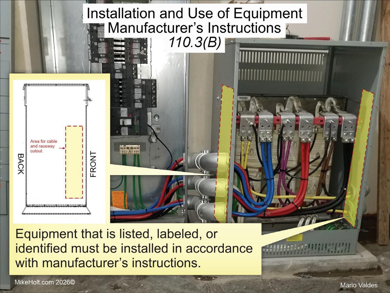
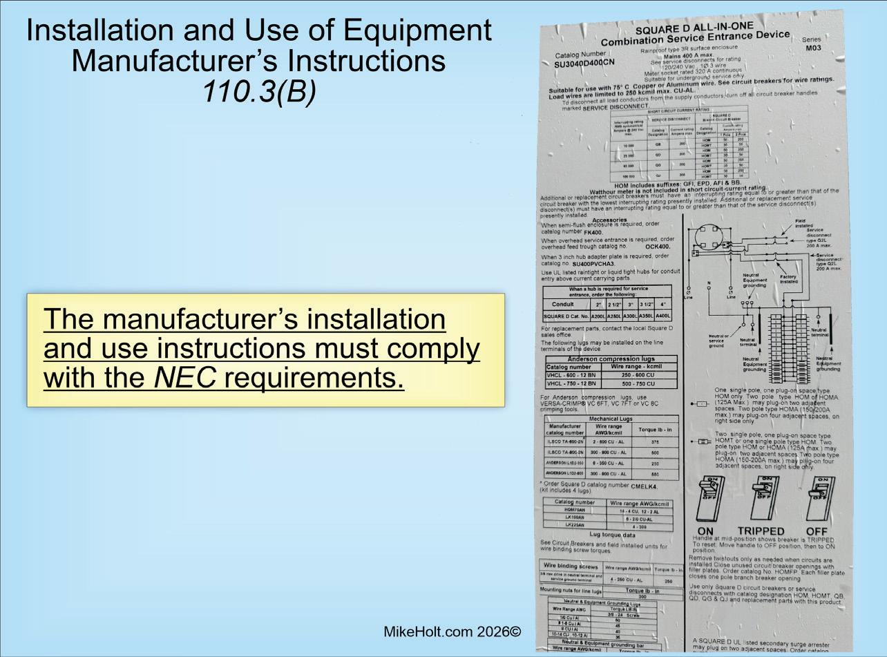
NEW Section 110.3(B) Manufacturer’s Instructions
Analysis of the change:
A manufacturer’s installation instructions cannot conflict with the NEC requirements. The instructions can exceed the NEC (where specified by the manufacturer), but you can never reduce the requirements of the Code.
(B) Installation and Use. Equipment that is listed, labeled, or identified must be installed in accordance with manufacturer’s instructions, as shown in Fig. 1.
New or revised Code language:
The manufacturer’s installation and use instructions must comply with NEC requirements (Fig. 2).
Note: The manufacturer’s installation instructions can be provided as printed material, quick response (QR) code, or web address to download (Fig. 3 on page 36).
Author’s comment:
Many electricians throw away installation instructions, but this is no longer a viable reason for not having access to them. Because manufacturers now use QR codes on electrical equipment, the
instructions are always readily available on their websites.
CHANGE #2 EXPANDED
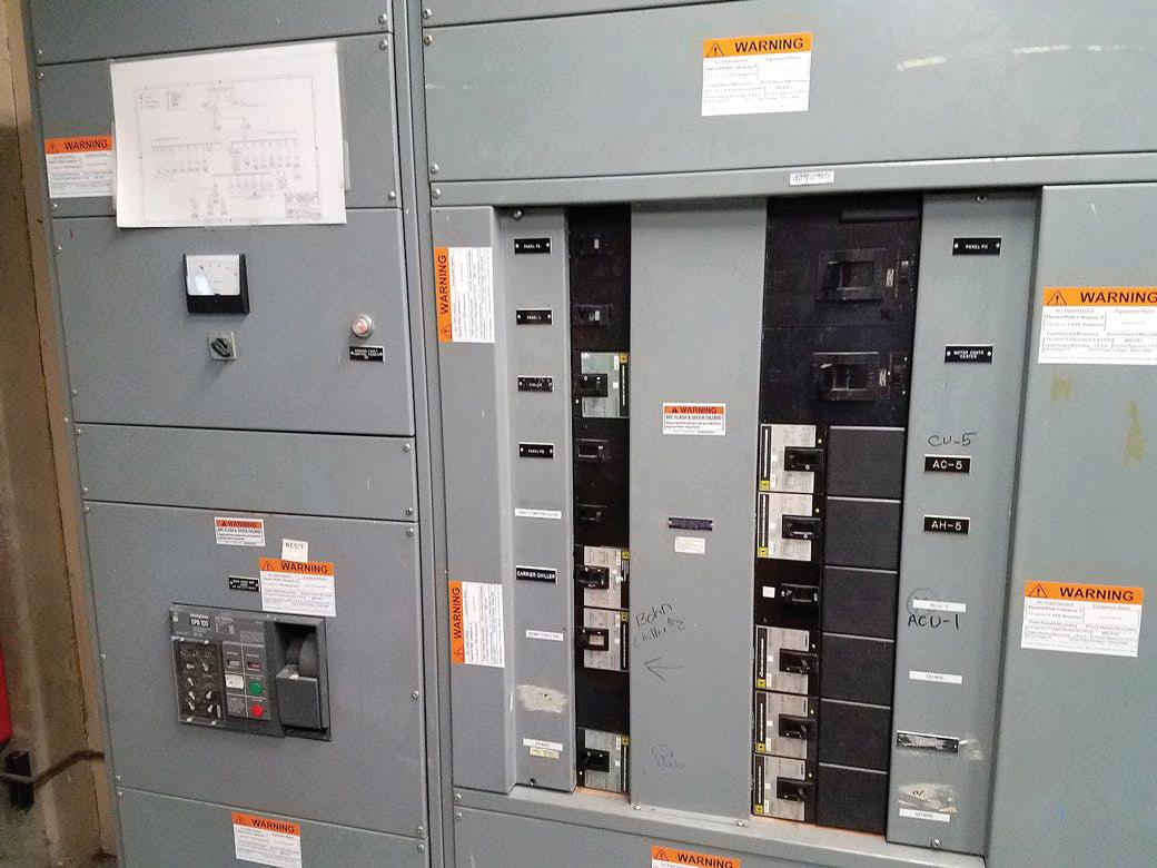
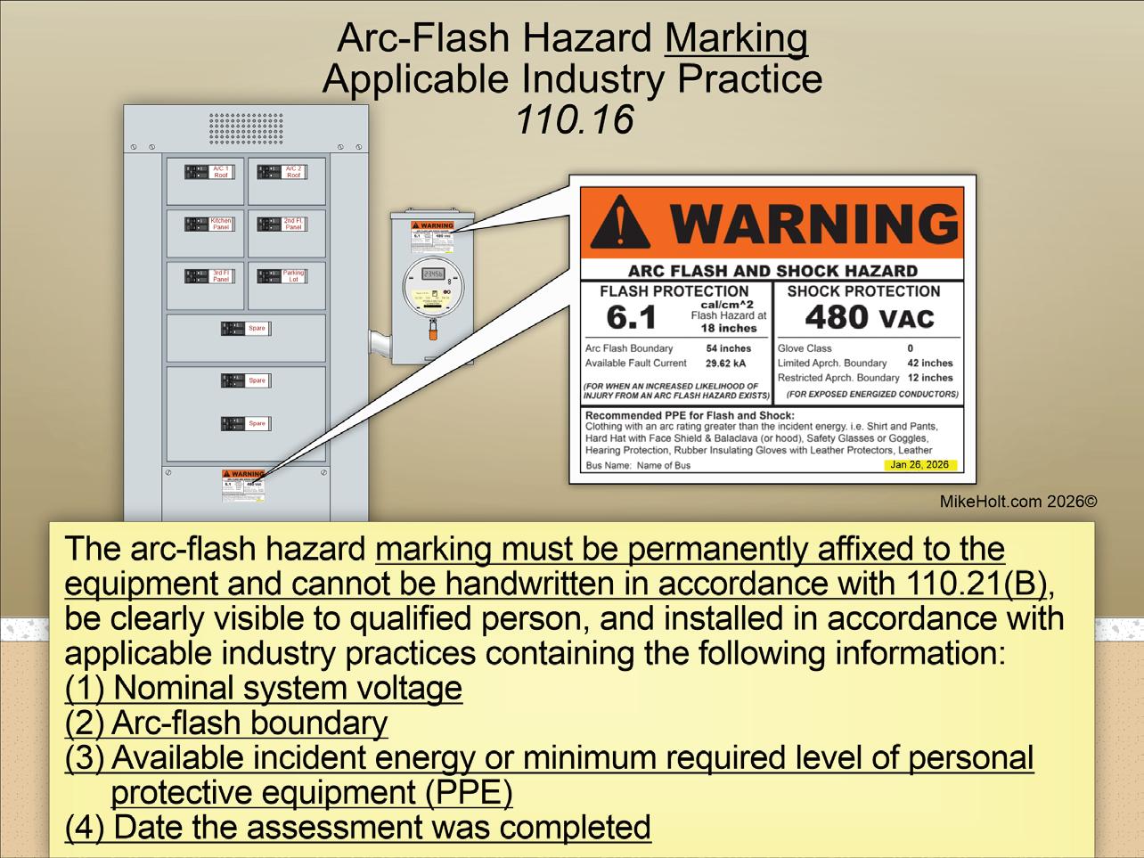
Section 110.16 Arc Flash Hazard Marking, Other Than Dwelling Units
Analysis of the change:
Arc flash warning label requirements for non-dwelling unit service and
feeder equipment were significantly expanded by deleting a few words. The previous Code only required arc flash warning labeling of service and feeder equipment of 1,000A or more. Now it’s required for all non-dwelling distribu tion equipment, and the arc flash label must include specific information (such as the date the arc flash assessment was completed).
New or revised Code language:
In other than permanent arc flash be applied to service and feeder equipment such as switchboards, enclosed panelboards, and meter socket enclosures (
Author’s comment:
An arc flash event can reach tempera tures of 35,000°F, which turns metal from a solid to gas vapors. This releases molten shrapnel that pierces the skin, causing severe burns — or even death. The reason the arc flash label is not required in dwelling units is the nominal voltage will be single-phase, 120V lineto-ground (240V line-to-line), so the arc fault will self-extinguish with every zero crossing of the sinusoidal waveform. A 3-phase arc fault is sustainable in accor dance with IEEE-1584


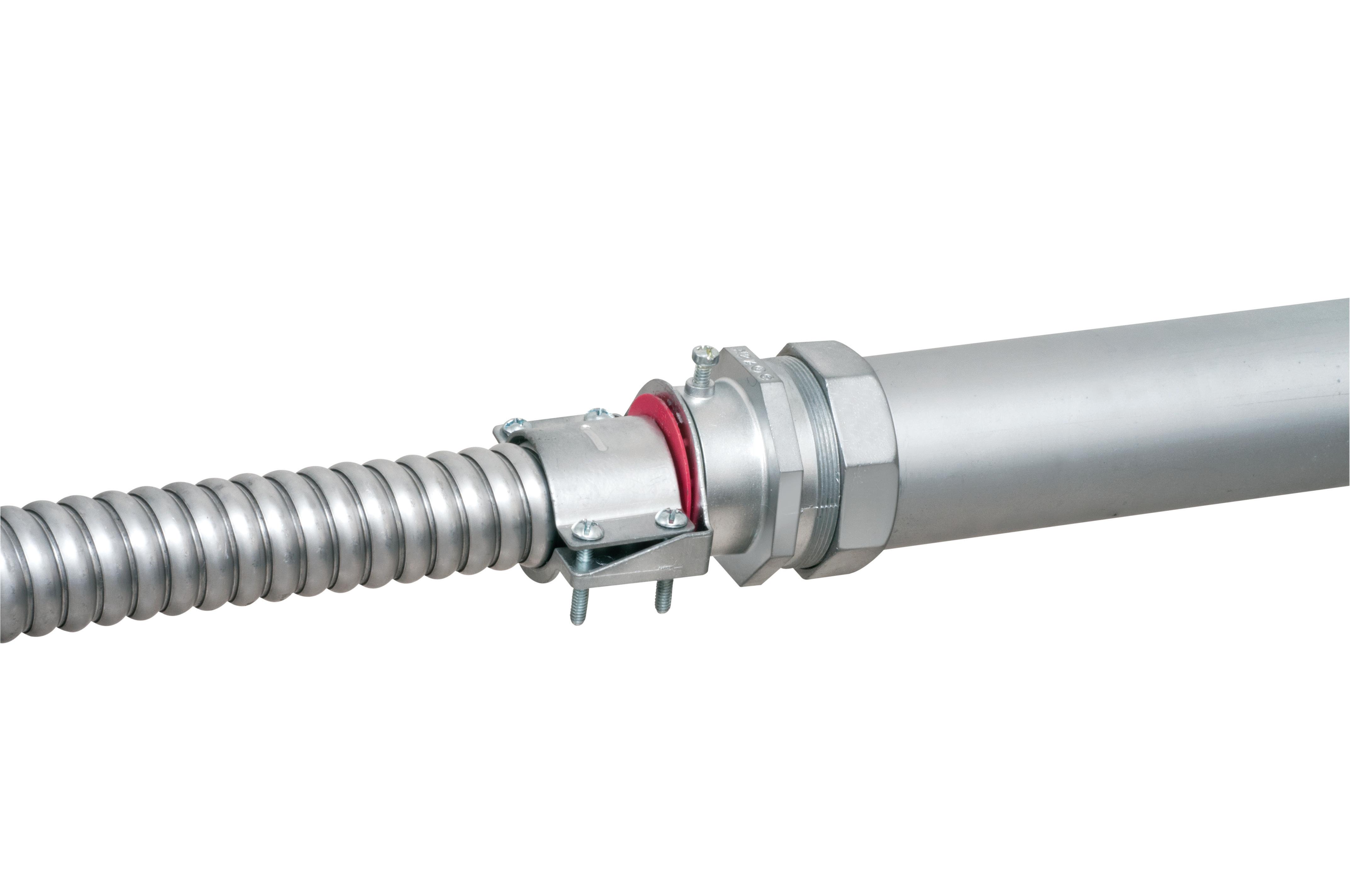
* Aluminum & Steel Flexible Metal Conduits

ONE trade size fits SEVERAL cable types and sizes, plus flexible metal conduit for super convenience and cost-savings! Reduces inventory and material handling too.

Patented
Conductor Size CSA TECK90 Conductor Size # of Conductors* # of Conductors* (AWG/KCMIL) (AWG/KCMIL/ACWU) 6/3, 6/4, 4-3, 4-4, 8/3, 8/4, 6/3
2-3, 2-4, 1-3
2-3, 2-4, 1-3, 1-4, 6/3, 6/4, 4/3, 4/4, 3/3, 1/0-3, 1/0-4, 2/0-3, 3/4, 2/3, 2/4
2/0-4, 3/0-3
2/0-4, 3/0-3, 3/0-4, 2/4, 1/3, 1/4, 1/0-3 4/0-3, 4/0-4, 250-3, 250-4 1/0-4, 2/0-3 250-4, 300-4, 350-3, 2/0-3, 2/0-4, 3/0-3, 3/0-4, 350-4, 500-3 4/0-3, 4/0-4, 250-3 500-3, 500-4, 600-3 4/0-4, 250-3, 250-4, 300-3 600-4, 750-3 300-4, 350-3, 350-4, 500-3 600-4, 750-3, 750-4 350-4, 500-3, 500-4 750-3, 750-4, 1000-4 750-3, 750-4, 1000-3
The arc flash hazard marking must be permanently affixed to the equipment and cannot be handwritten in accordance with Sec. 110.21(B), be clearly visible to a qualified person, and be installed in accordance with applicable industry practices containing the following information:
(1) Nominal system voltage
(2) Arc flash boundary
(3) Available incident energy or minimum required level of personal protective equipment (PPE)
(4) Date the assessment was completed (Fig. 5 on page 38)
Note 2: NFPA 70E, Standard for Electrical Safety in the Workplace, provides applicable industry practices for developing arc flash equipment markings that include nominal system voltage, incident energy levels, arc flash boundaries, and by selecting an appropriate level of personal protective equipment.
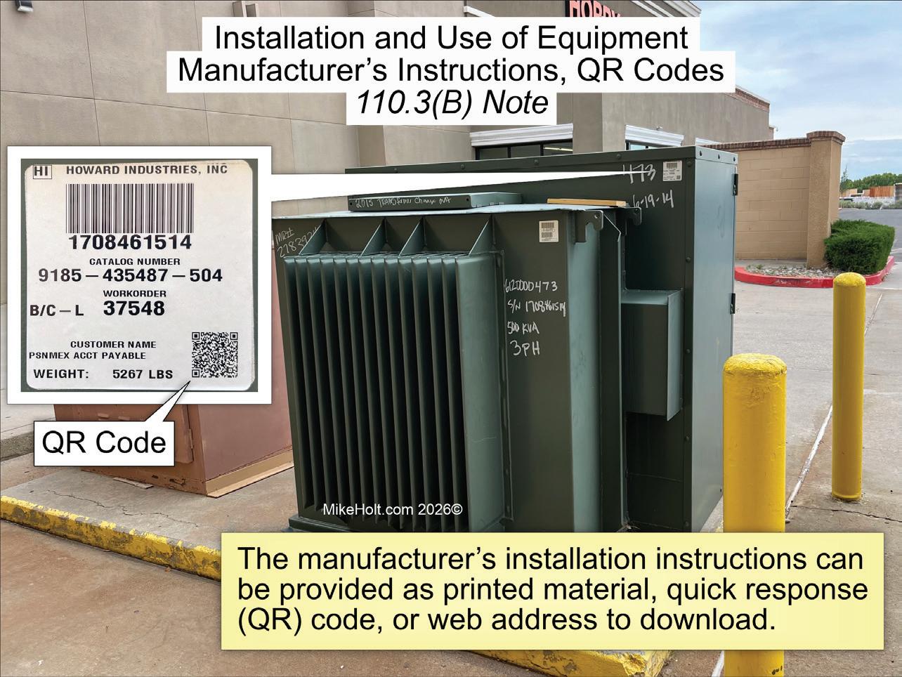
Fig. 3.
NEW
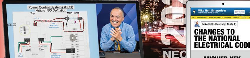
Section 120.7(B) Power Control Systems (PCSs)
Analysis of the change:
For load calculations, we can use a listed PCS with a control setting not exceeding 80% of the overcurrent protective device. This prevents overload of the branch-circuit, feeder, or service conductors. Controlling loads with a PCS
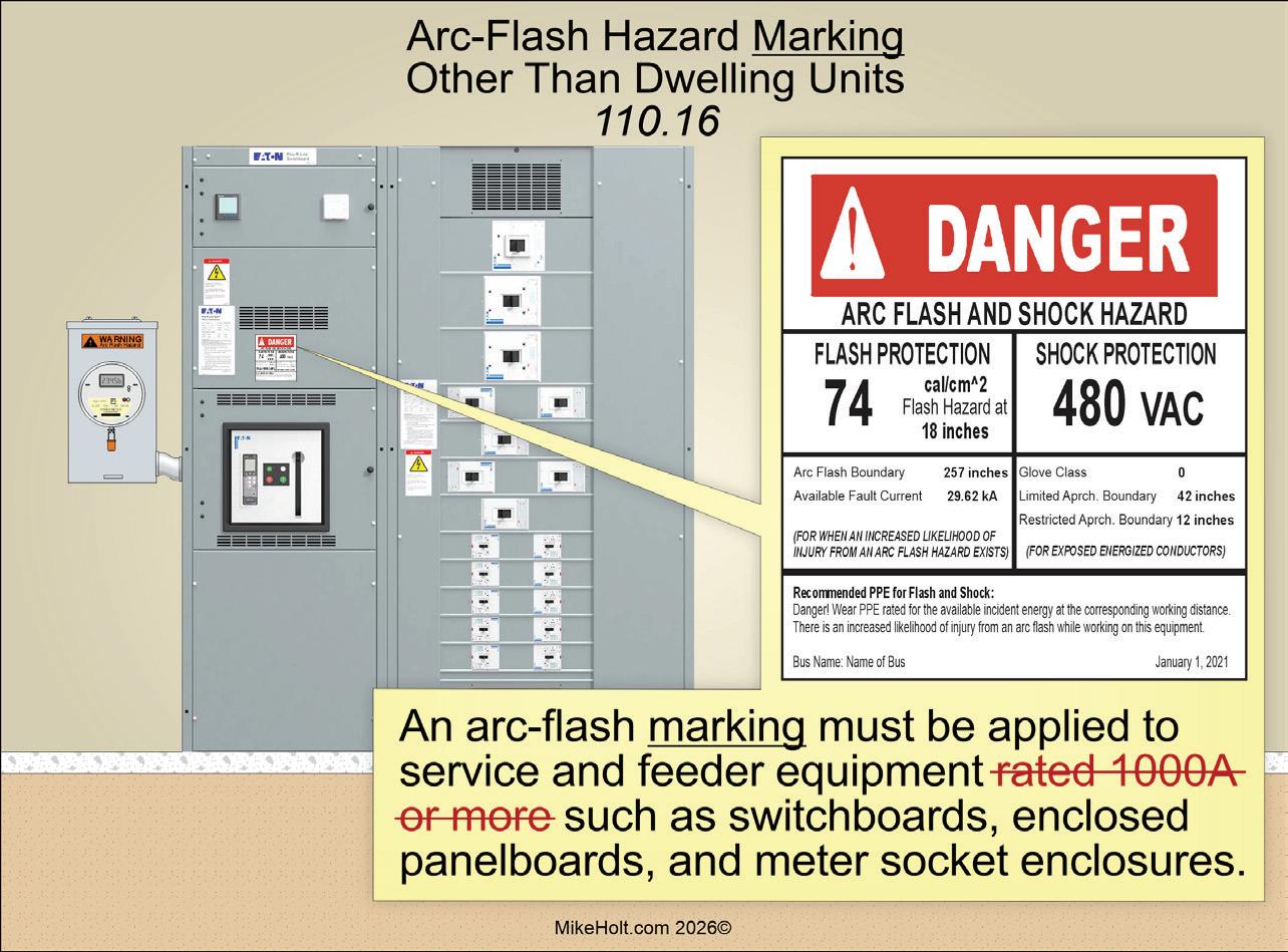
Fig. 4.
avoids an expensive upgrade if your panel or service is near capacity.
New or revised Code language:
(B) PCS Control Setting. When used in load calculations, the control setting is not permitted to exceed 80% of the overcurrent protective device rating for the circuit being monitored by the PCS (Fig. 6 on page 38).
NEW
Section 120.7(C) Power Control Systems (PCSs)
Analysis of the change:
A new rule clarifies how to calculate loads monitored and managed by a power control system (PCS) by distinguishing between controlled and non-controlled loads. This provides clearer direction when sizing loads with PCS technology. An Informational Note was added to give examples of how load calculations should be handled when a PCS is used to manage connected loads.
New or revised Code language:
(C) Load Calculations Using PCS. The load on the branch circuit,


Extra-duty one-piece design
Pre-installed strut clip for faster installation on strut
Stainless steel screw

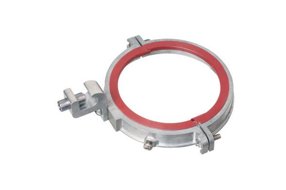
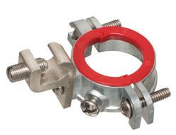
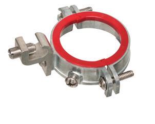
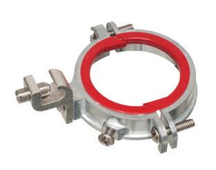
Arlington’s corrosion-resistant QUICKLATCH™ pipe hangers cost the same as a steel pipe hanger with a bolt and nut – but better. They’re faster and easier to install. And SAVE 25 seconds* per installation!
• UV rated for outdoor use
• Listed for environmental air handling spaces
• For thin walls, rigid conduit, PVC conduit or copper
feeder, or service must be the sum of the controlled loads. Controlled loads are determined in Sec. 120.7(C)(1), and noncontrolled loads are determined in Sec. 120.7(C)(2).
(1) Controlled Loads. Controlled loads must be based on the monitoring by the PCS to provide overload control. The PCS control configuration must comply with one or both of the following:
(1) If the PCS monitors only controlled loads, the control setting must be used in place of the controlled loads in load calculations.
(2) If the PCS monitors both controlled and noncontrolled loads, the minimum operating current of the controlled loads must be used in place of the controlled loads in load calculations.
Note: Minimum operating current is a value greater than or equal to zero representing the minimum current of the controlled loads.
5.
(2) Noncontrolled Loads. Load calculations for loads not controlled by the PCS must comply with Art. 120, Parts II through VII.
Note: See Informative Annex D Examples D14(a) through D14(d) for examples of load calculations with loads managed by PCSs.

Fig. 6.
CHANGE #5
NEW Section 120.82(B) General Lighting Demand, First 8kVA
Analysis of the change:
The demand load for optional dwelling unit load calculations was reduced from the first “10kVA” at 100% to the first “8kVA” at 100%. The effect is a slightly smaller demand load — the treatment of the first 10kW of load at 100% is reduced.
New or revised Code language:
(B) General Loads. The demand load must not be less than 100% of the first 8kVA, plus 40% of the remaining kVA for the following loads.
NEW
Section 120.82(B) General Lighting Load, 2VA
Analysis of the change:
Based on studies by the Department of Energy, the general lighting and receptacle load in a dwelling unit was reduced from “3VA” to “2VA” per square foot for feeder/service load calculations.

Arlington’s new one-piece RETROFIT SNAP2IT® fittings are easy to use in an OLD WORK installation, and handle the widest variety of cables! They’re ideal for adding additional circuits to a load center. And you get the same labor-savings in a retrofit installation!
Easy snap-in installation - NO TOOLS. Install connector into the knockout in an existing box, pulling cable/conduit through the knockout. Slip the fitting onto the cable, then snap the assembly into the box. That’s it... a secure installation with no pullout
Widest total cable ranges 14/2 to 10/3
Widest variety of cables AC, MC, HCF, MC continuous corrugated aluminum cable, MCI-A cables (steel and aluminum), AC90,


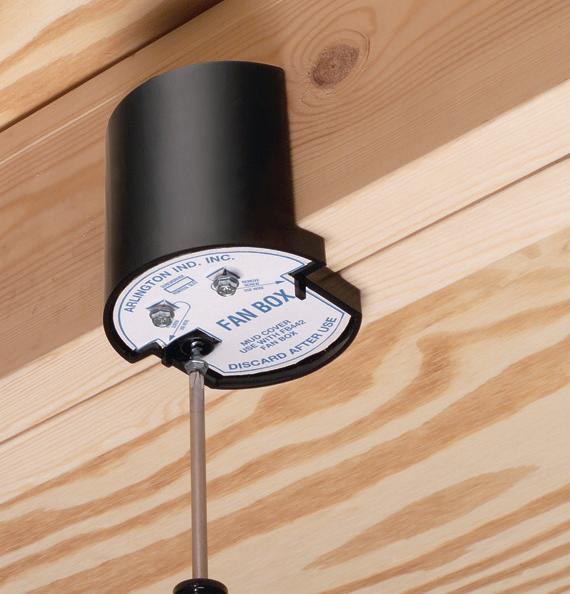
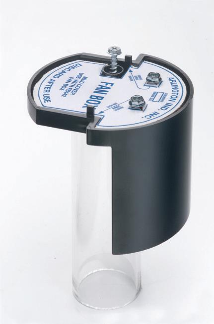
Arlington’s heavy-duty, plated steel fan/ fixture box has an adjustable bracket that mounts securely between joists spaced 16" to 24" o.c.
Flush ceiling installations

FBRS415 is designed for ceilings up to 1-1/4" thick. For 1/2" ceilings, use the pre-bent positioning tab. For other ceiling thicknesses, bend along the appropriate score line. • 15.6 cu. inch

(1) General Lighting. The general lighting load is based on 2VA per sq ft for general lighting and general-use receptacles. The sq ft area is determined in accordance with Sec. 120.5(C).
(2) Small-Appliance and Laundry Circuits. Add 1,500VA for each 20A small-appliance circuit required by Sec. 210.11(C)(1)(a) with a minimum of two circuits per dwelling unit, and 1,500VA for each 20A laundry circuit required by Sec. 210.11(C)(2), with a minimum of one circuit per dwelling unit.
(3) Appliances. The nameplate rating of the following appliances:
a. Appliances that are fastened in place, permanently connected (hard-wired), or located on a specific circuit
b. Ranges, wall-mounted ovens, and counter-mounted cooking units
c. Clothes dryers that are not connected to the laundry branch circuit
d. Water heaters

(4) Motor VA. The nameplate ampere or kVA rating of all permanently connected motors not included in Sec. 120.82(B)(3).
(C) Air-Conditioning and Heating Equipment. The larger of Sec. 120.82(C)(1) through (6):
(1) Air-Conditioning Equipment. Use 100% of the air-conditioning nameplate ratings.
(2) Heat-Pump Compressor without Supplemental Heating. Use 100% of the heat-pump nameplate rating.
(3) Heat-Pump Compressor with Supplemental Heating. Use 100% of the nameplate rating of the heat pump, and use 65% of the supplemental electric heating for central electric space-heating systems.
(4) Space-Heating Units (Three Units or Less). Use 65% of the nameplate ratings.
(5) Space-Heating Units (Four or More Units). Use 40% of the nameplate ratings.
(6) Electric Thermal Storage and Other Heating. Use 100% of the nameplate rating.
CHANGE #7 NEW Section 120.82(D) Electric Vehicle Supply Equipment Load at 100%
Analysis of the change:
For the dwelling unit optional method, the electric vehicle supply equipment (EVSE) load is required to be calculated


Arlington’s steel SliderBar® offers the easy, NEAT way to mount single or two-gang boxes between wood or metal studs with non-standard stud cavities.
No more cutting, nailing and fitting extra 2x4s to fill the space! SliderBar saves about 20 minutes per box. Designed for studs spaced 12” to 18” apart, SL18 allows positioning of one or more boxes anywhere in the stud cavity.
• Bending guides on bracket assure proper positioning on studs
• Interlocking tab stop prevents accidental disassembly

• Pre-punched pilot holes on BOTH sides of S for easy attachment of one or two boxes
at 100% with no demand factor because it represents a significant load.
New or revised Code language:
(D) Electric Vehicle Supply Equipment (EVSE). Use 100% of the electric vehicle supply equipment nameplate rating in accordance with Sec. 120.57.
CHANGE #8
NEW Section 130.50 General
Analysis of the change:
Power control system (PCS) requirements were added to a new Part II of Art. 130. There are two types of energy management systems (EMSs). A traditional EMS monitors energy usage and control loads to save money. Power control systems (PCSs) add the capability to monitor and control loads to prevent the overloading of conductors or equipment and improve system performance.
New or revised Code language:
Part II contains the requirements for PCS of an energy management system. A PCS may control generation, energy storage, loads, circuit controllers, or other equipment to manage power. It

may contain additional protective functions relative to EMS or grid interconnection functions.
CHANGE #9
EXPANDED
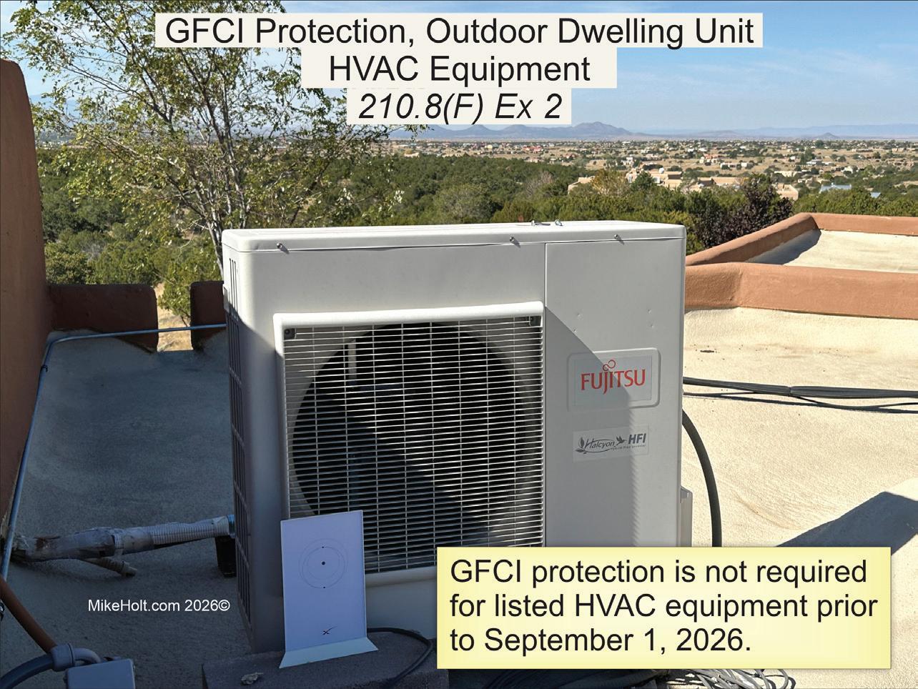
Sec. 210.8 GFCI Protection
Analysis of the change:
GFCI protection requirements for outdoor outlets in dwellings (such as pool heaters and air-conditioning compressors) were increased from “50A” to “60A”
as GFCI solutions are readily available and the hazards are the same.
New or revised Code language:
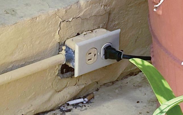
(F) Outdoor Dwelling Unit Outlets. GFCI protection is required for all outdoor outlets, rated 60A or less, located outside a dwelling unit and (Fig. 7 on page 40):
(1) Outside dwelling garages
(2) Outside dwelling accessory buildings
(3) Outside dwelling boathouses
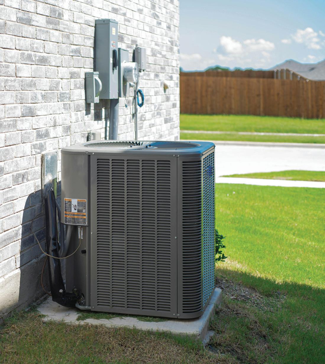
Exception No. 2: GFCI protection is not required for listed HVAC equipment prior to Sep. 1, 2026 (Fig. 8 on page 40).
Author’s comment:
In accordance with UL 60335-2-40, listed HVAC equipment includes airconditioning and heat pumps used for cooling and heating.
CHANGE #10
NEW
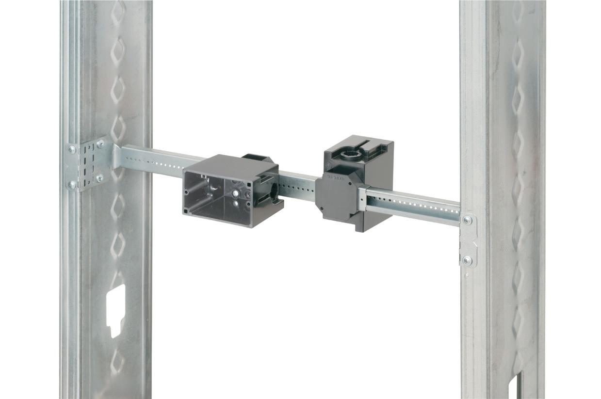
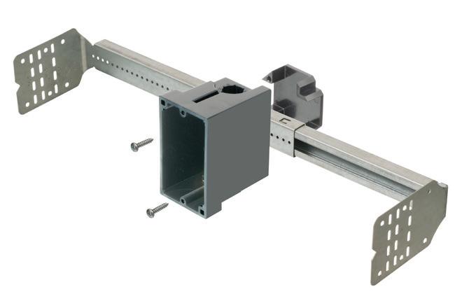
Section 210.52(A)(5) Wall Receptacle Outlets Below Countertop
Analysis of the change:


Receptacle outlets are now prohibited within 24 in. below the countertop surface. The 2023 Code addressed the Consumer Product Safety Commission reports on incidents caused by hanging cords off kitchen island and peninsula tops. However, it unintentionally allows other receptacles to be mounted on the sides of kitchen islands and peninsulas. Therefore, the rule was revised to prohibit “required and permitted” wall receptacle outlets installed below freestanding bar-type counters within 24 in. of the countertop surface.
New or revised Code language:
(5) Prohibited Receptacle Outlet Locations. Wall space receptacle outlets required by Sec. 210.52(A) (2)(3) installed below countertops are not permitted to be located within 24 in. of the countertop (Fig. 9 on page 42).
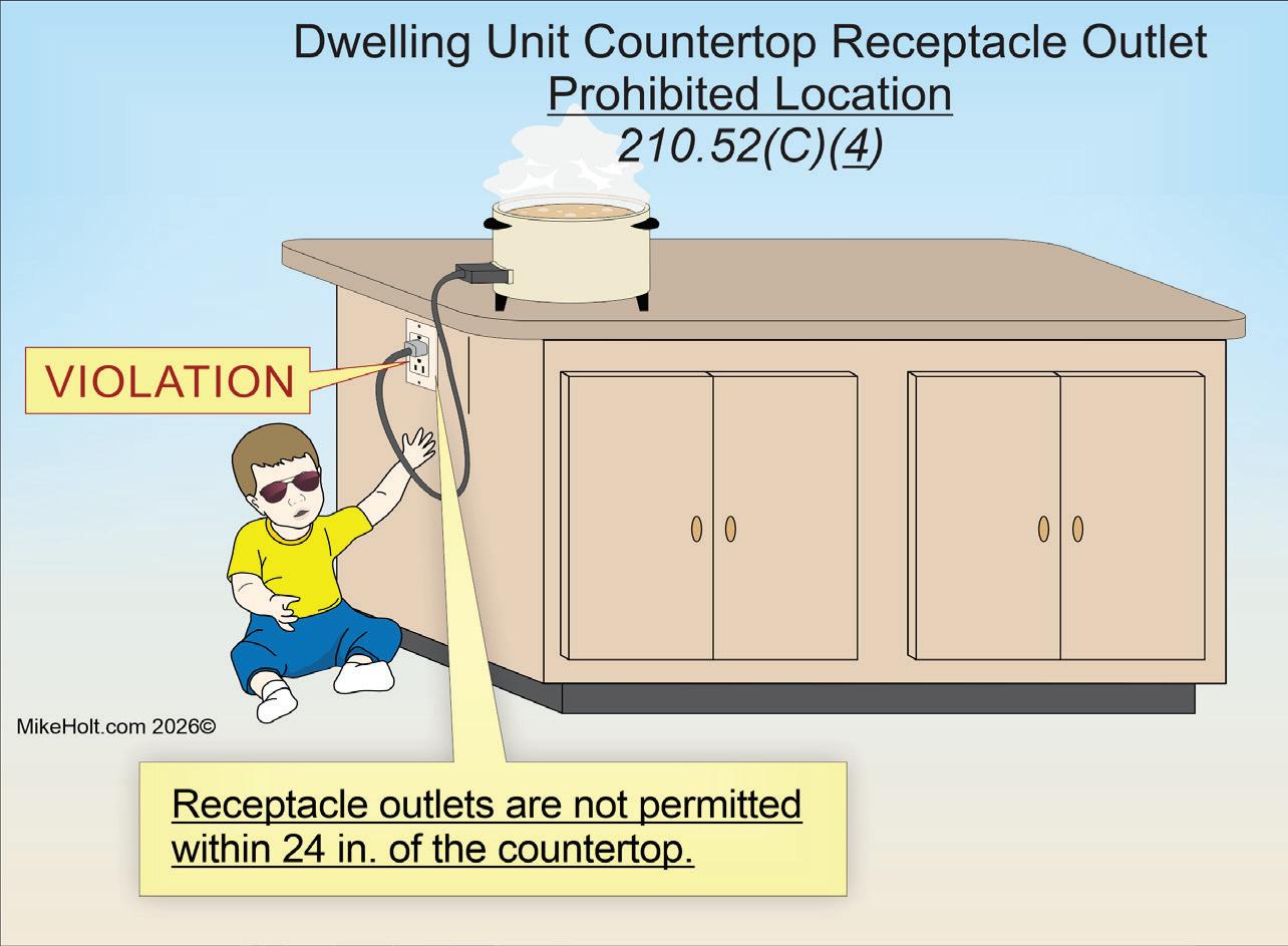
Section 210.52(C)(4) Receptacle Outlets Below Countertop
Analysis of the change:
Receptacle outlets are prohibited within 24 in. below the countertop surface. The 2023 Code changed countertop receptacle requirements to address the Consumer Protection Safety Commission reports of children suffering burn injuries from pulling appliance cords hanging off kitchen islands and peninsula countertops. These changes unintentionally allowed other permitted receptacles to be placed in these areas, creating the same hazard. The rule was revised this cycle to prohibit both “required and permitted” receptacle outlets from being located within 24 in. of the kitchen countertop surface.
New or revised Code language:
(4) Prohibited Receptacle Outlet Locations. Receptacle outlets are not permitted within 24 in. of the countertop (Fig. 10 on page 42).
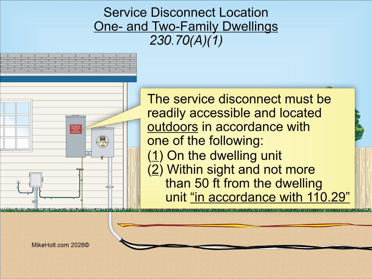

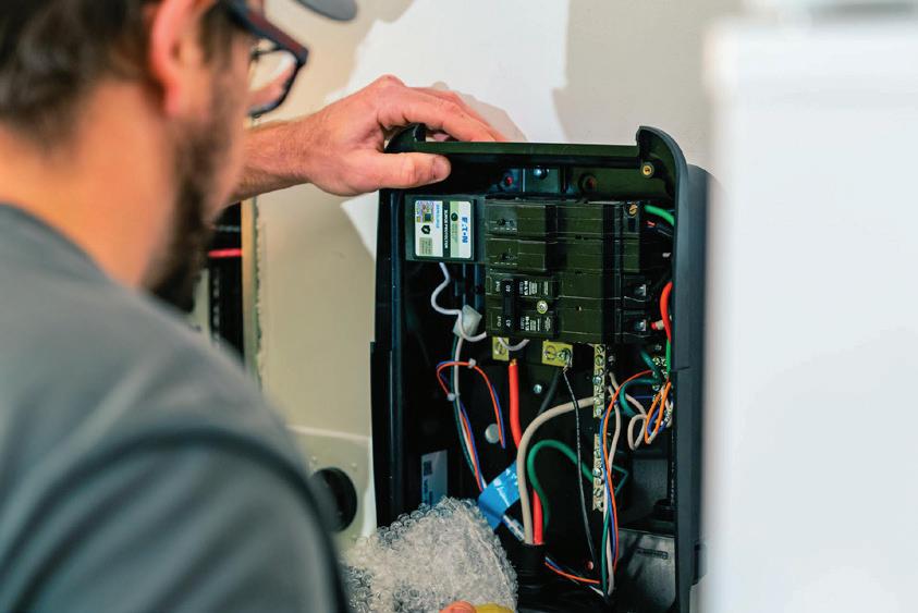
Section 230.70(A) Service Disconnect Location
Analysis of the change:
Service disconnects for one- and two-family dwellings must be located outdoors. The emergency disconnect rules in Sec. 230.85 were deleted. Now the service disconnects for one- and two-family dwellings must be
outside, on, or within sight of the dwelling unit in accordance with Sec. 110.29.
New or revised Code language:
(A) Service Disconnect Location. Service equipment disconnects must be installed in accordance with the following:
(1) One- and Two-Family Dwellings. The service disconnect
Foldline (centerline)
Locking tab

Bend right side of strap in and over cable

Arlington’s economical CUS6 galvanized steel Cable Support holds cable secure and centered on a metal or wood stud.
It’s perfect for fastening and individual metal clad cables –or six NM cables on a 2x4. to a wood or metal stud, and position the cables. Next bend the strap at the foldline (centerline). Fold the strap over the cables and insert the locking tab in the opening as shown to hold FOUR
Nail or screw to stud through these holes Product
Insert locking tab here


Arlington’s recessed STEEL combination power/low voltage TV BOX® is the best way to mount an LED or Hi-Def TV flush against a wall.
TV BOX provides power and/or low voltage in one or more of the openings. Plugs and connectors stay inside the box, without extending past the wall.
Designed for use in new or retrofit commercial construction where metal raceway is used, we have a STEEL TV BOX for almost any application!

• Steel box; non-metallic paintable white trim plate
• Easy, secure installation
• Optional covers


must be readily accessible and located outdoors in accordance with one of the following:
(1) On the dwelling unit.
(2) Within sight and not more than 50 ft from the dwelling unit in accordance with Sec. 110.29 (Fig. 11 on page 44).
Section 230.70(B) Service Disconnect Markings
Analysis of the change:
The marking requirements of the service disconnect were significantly revised. These new marking rules make it clear exactly how to label and where the label is required for service disconnects.
New or revised Code language:
(B) Service Disconnect Marking Service disconnects must be marked as follows:
(1) Marking, Other than Oneand Two-Family Dwellings. Service disconnects must be marked “SERVICE DISCONNECT” on or adjacent to the service
13.
disconnect. The marking must be of sufficient durability to withstand the environment, cannot be handwritten, and must be permanently affixed to the equipment in accordance with Sec. 110.21(B), as shown in Fig. 12 on page 44.
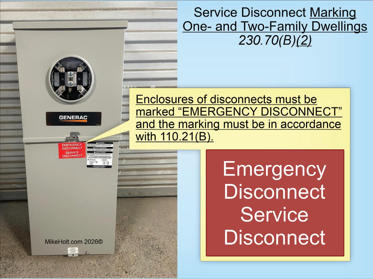
(2) Marking, One- and TwoFamily Dwellings. Enclosures
14.
of disconnects for one- and two-family dwellings must be marked “EMERGENCY DISCONNECT.” The marking must be of sufficient durability to withstand the environment, cannot be handwritten, and must be permanently affixed to the equipment in accordance with Sec. 110.21(B), as shown in Fig. 13
(1) Markings must be located on the outside front of the disconnect enclosure with a red background and white text
(2) Lettering must be at least ½ in. high
(D) Identification of Source Disconnects. Where the disconnecting means for energy source systems is not located adjacent to the service disconnect, a plaque or directory identifying the location of all energy source disconnecting means must be located adjacent to the service disconnect.
Note: For examples of energy source system disconnection means, see Secs. 445.18, 480.7, 705.20, and 706.15.
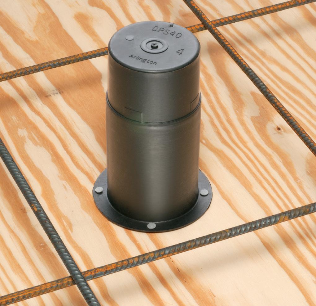
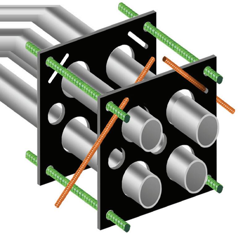
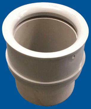
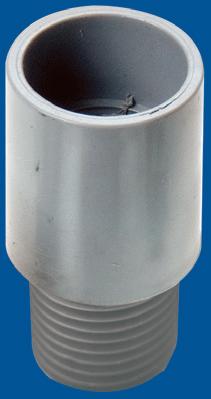
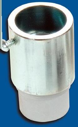
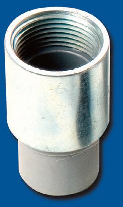
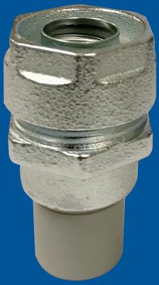
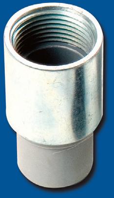
Arlington’s Concrete Pipe Sleeves are the economical way to sleeve through concrete pours in tilt-up construction WALLS – and FLOORS allowing cable and conduit to run easily from one floor to the next.
No costly core drilling – No cutting holes in the form. Plus, you can position the hole prior to pouring the concrete.
• Attaches to form with nails or screws
• Stackable up to 23" h for extra deep pours
• Vents keep wet pipe sleeves from sticking together
• Multiple hole sizes: 1-1/2"


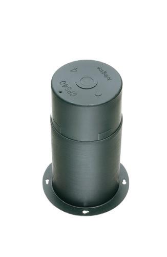

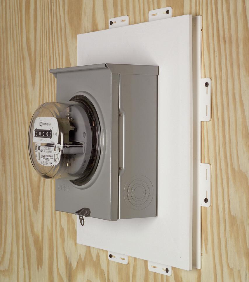
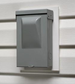
Arlington’s one-piece, non-metallic Mounting Bases provide a smooth, flat mounting surface for most electric meters, including the largest sizes – as well as a variety of other products such as timers, disconnects, inlet boxes and more.
UV rated, paintable plastic for long outdoor life.
Squared-off corners make them gangable so you can create the mounting base needed for the product you’re installing.


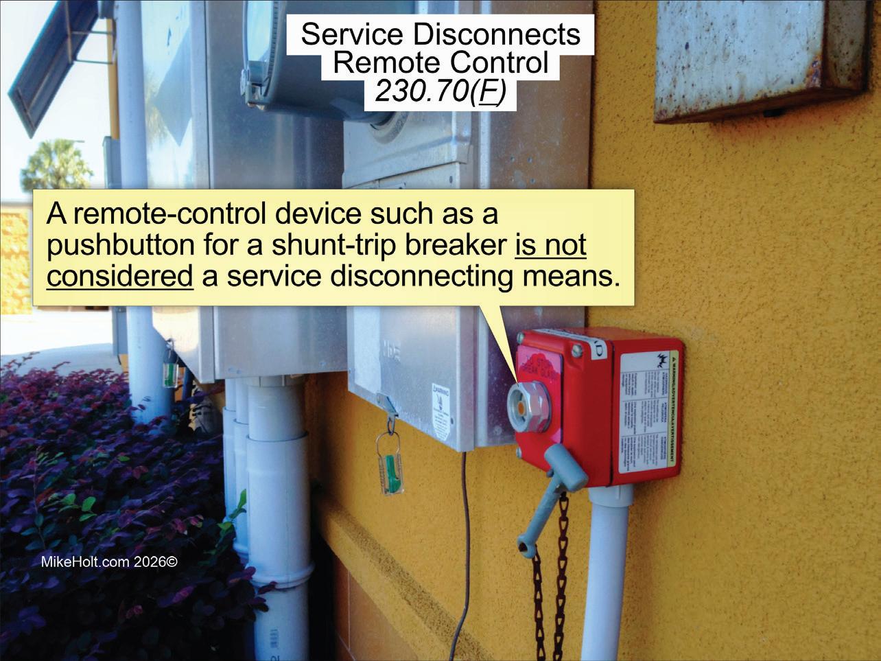
Section 230.70(F) Remote Control
Analysis of the change:
Remote disconnect control requirements were clarified by stating that in no case is a remote-control device permitted to be used as the service disconnect.
New or revised Code language:
(F) Remote Control. A remotecontrol device (such as a pushbutton for a shunt-trip breaker) is not considered a service disconnecting means (Fig. 14 on page 46).
NEW
Section 300.4 Limitations
Analysis of the change:
The NEC now addresses overheated, fire-damaged, or water-damaged wiring. A new rule states that overheated, fireor water-damaged conductors, wiring methods, and equipment must be replaced. Two new Informational Notes refer to NEMA documents for evaluating fire- and water-damaged electrical equipment. This change removes any
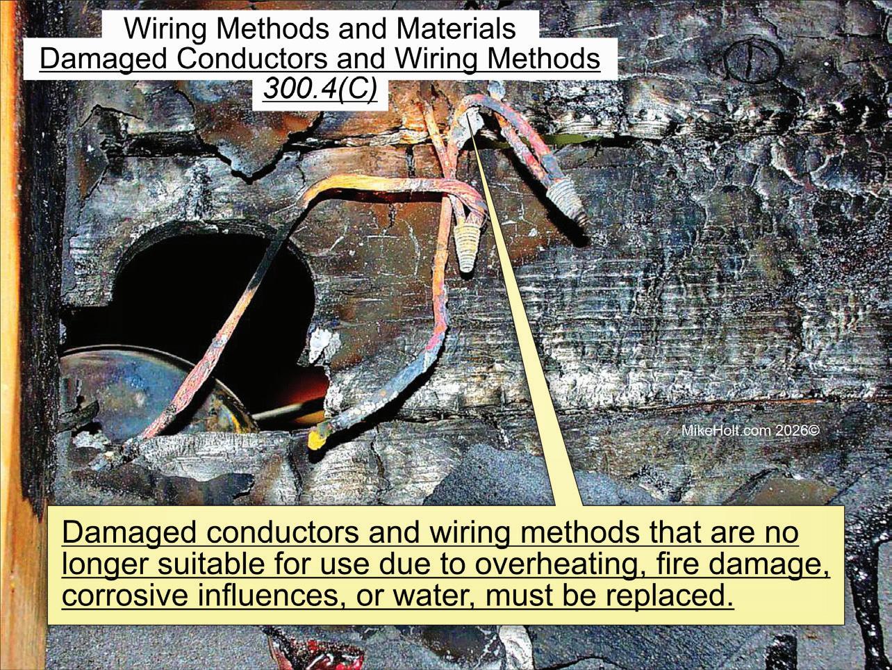
Fig. 15.
doubt that damaged wiring and equipment must be removed and replaced.
New or revised Code language:
(C) Damaged Conductors and Wiring Methods. Damaged conductors and wiring methods that are no longer suitable for use (due to overheating, fire damage, corrosive influences, or water)
Fig. 16.
must be replaced (Fig. 15).
Note 1: For information on electrical equipment and wiring methods damaged by water, see NEMA GD 1-2019, Evaluating WaterDamaged Electrical Equipment (Fig. 16).
Note 2: For information on electrical equipment and wiring methods damaged by fire or heat, see NEMA GD 2-2021, Evaluating Fire- and Heat-Damaged Electrical Equipment (Fig. 17 on page 50).
NEW
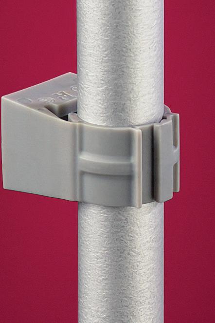
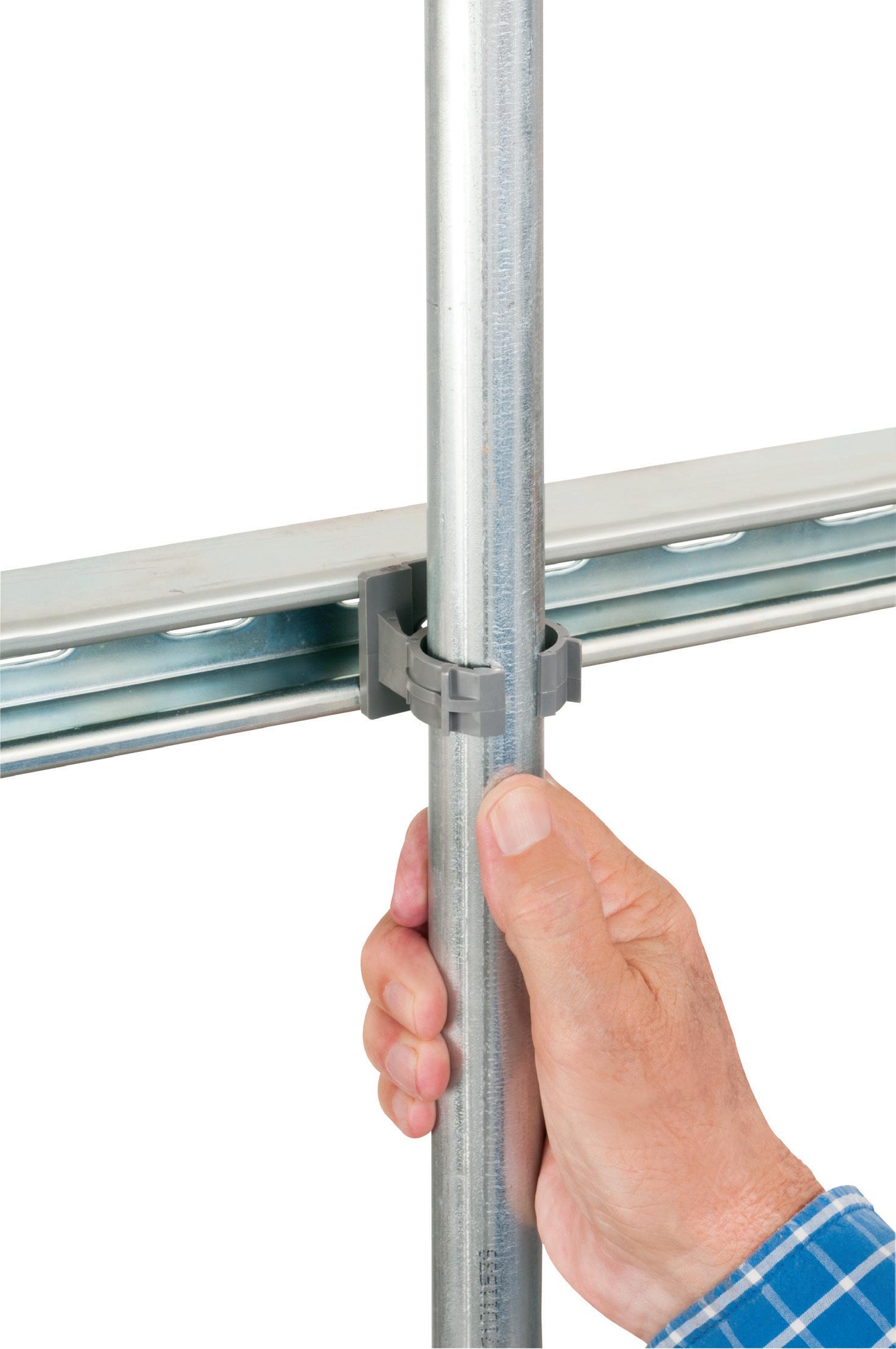
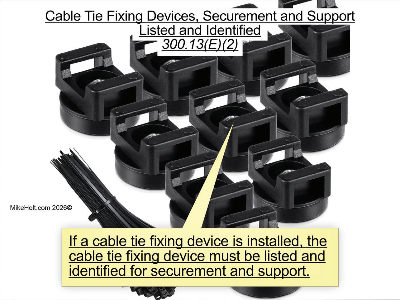
Section 300.13 Securing and Supporting
Analysis of the change:
A new rule specifies that cable ties used for supporting and securing cables or flexible raceways must be listed and identified for that purpose. A new Informational Note provides guidance on which cable tie type is evaluated for securing and supporting.
New or revised Code language:
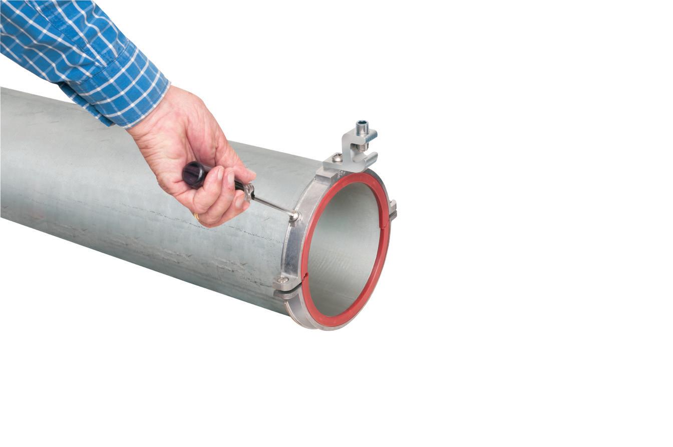
(E) Cable Ties Used as Means of Securement and Support.


(1) Cable Ties. Cable ties used as a means for securement and support for cable, flexible conduit, and flexible tubing must be listed and identified for securement and support (Fig. 18).
(2) Cable Tie Fixing Devices. If a cable tie fixing device is installed, the cable tie fixing device must be listed and identified for securement and support (Fig. 19 on page 52).
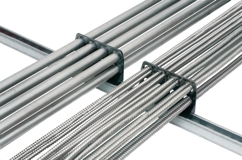
Note: Type 2S and 21S cable ties are evaluated for securing and supporting cable, flexible conduit, and flexible tubing.
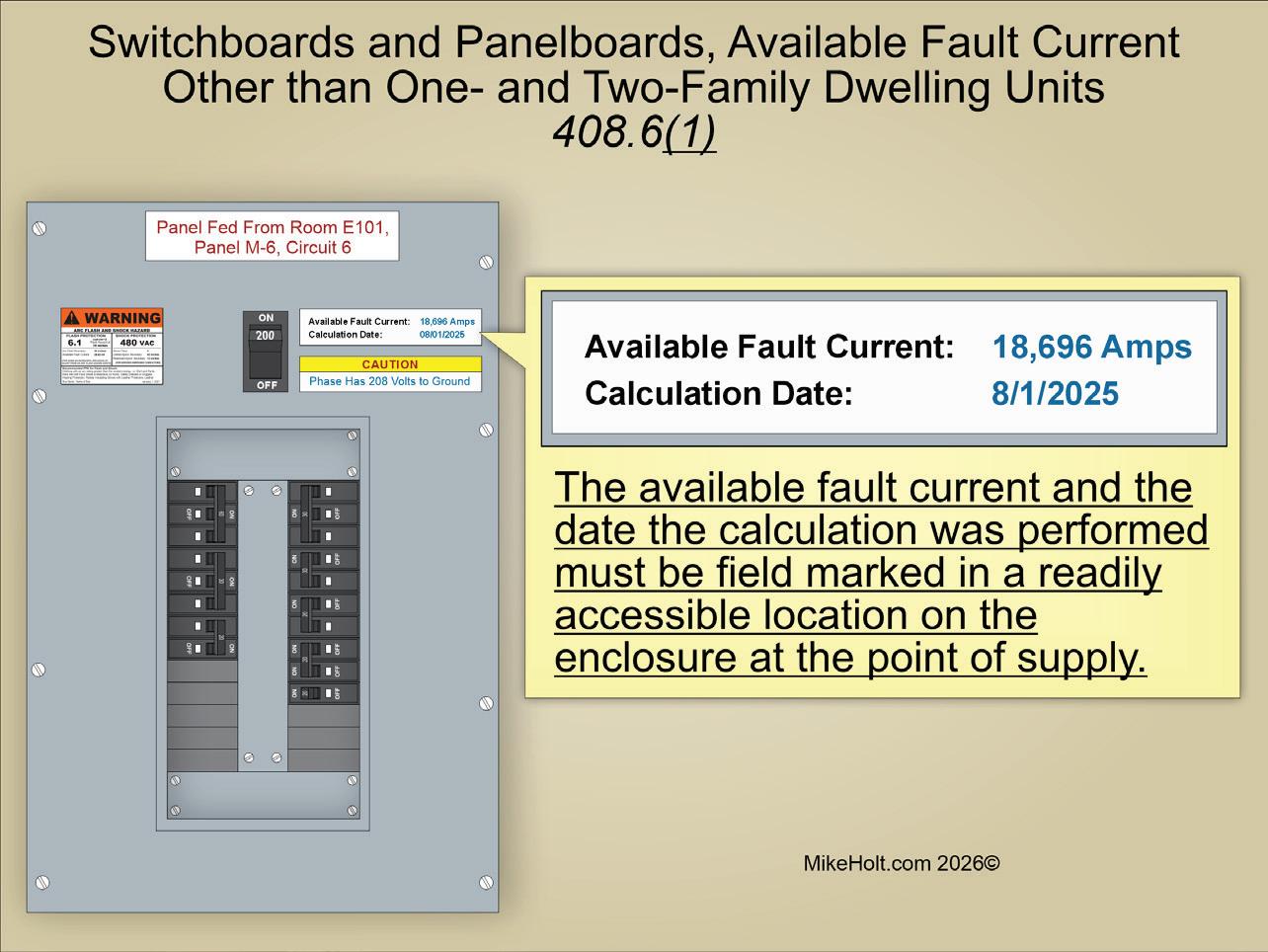
Section 408.6 Short-Circuit
Analysis of the change:
There are new requirements for marking, documenting, and recalculating available fault current at the line terminals of panelboards and switchboards for other than one- and two-family dwellings.
New or revised Code language:
Switchboards and panelboards must have a short-circuit current rating not less than the available fault current on the line side of the equipment. In other than one- and two-family dwelling units, switchboards and panelboards must comply with the following:
(1) Available fault current and the date the calculation was performed must be field marked in a readily accessible location on the enclosure at the point of supply (Fig. 20 on page 53).
(2) Short-circuit current rating of switchboards and panelboards, at nominal circuit voltage (based on the overcurrent protective device), must be field marked in a readily accessible location on the enclosure


(3) Marking required by Sec. 408.6(1) and (2) must comply with Sec. 110.21(B)
(4) Available fault current calculation must be documented and made available to those authorized to inspect, install, or maintain the installation
(5) Where modifications occur that affect the available fault current at the line terminals of the equipment, the following applies:
a. Available fault current must be recalculated as necessary to ensure the equipment ratings are not less than the available fault current at the line terminals of the equipment


19.
b. Required field markings in Sec. 408.6(1) must be adjusted to reflect the new level of available fault current
The interrupting rating of the replacement or added overcurrent
protective devices must be equal to/greater than the available fault current marked on the equipment.
Note: For series combination systems, see Sec. 110.22.
Analysis of the change:
A new rule permits the authority having jurisdiction (AHJ) to require an engineered electrical design for one- and two-family dwelling pier distribution systems in some cases. For larger systems or multi-slip marinas, be prepared to submit engineered plans. This change improves public safety on commercial docks by ensuring proper design and installation.
New or revised Code language:
Documentation of an engineered electrical design of the pier distribution system must be provided upon request of the authority having jurisdiction (AHJ).
Exception: An engineered design is not required for one- and two-family dwelling units if the system voltage is 240V, singlephase, or less.
• Article 120. Branch-Circuit, Feeder, and Service Load Calculations. Relocated from Art. 220, Art. 120 contains the requirements necessary for calculating demand loads for branch circuits, feeders, and services. This change was made because load calculations apply generally to all installations.
• Article 130. Energy Management Systems. As part of the larger reorganization of the NEC, requirements for energy management systems (previously contained in Art. 750) were relocated to Art. 130. Part I applies to both energy management systems (EMSs) and power control systems (PCSs), which are EMS that also provide overload protection. Part II applies only to power control systems.
• Article 206. Non-Power-Limited Remote-Control and Signaling Circuits. This Article provides the general requirements for non-power-limited remote-control and signaling circuits.
• Article 406. The scope of Art. 406 was revised to cover “wiring devices” instead of just receptacles. Under the new Art. 100 definition, wiring devices now include receptacles,
cord connectors, attachment plugs, snap switches, dimmers, and electronic control switches. The major shift was relocating small switch-type wiring devices from Art. 404 into Art. 406. This reorganization groups devices with similar construction and performance requirements under one article, improving the clarity and usability of the Code. This Article contains the requirements for the rating, type, and installation of wiring devices.
• Article 624. Electric Self-Propelled Vehicle Power Transfer Systems (ESVSEs). This Article covers the electrical conductors and equipment connecting an electric self-propelled vehicle (ESV) to premises wiring for the purposes of charging, power export, or bidirectional current flow. It applies to vehicles not defined as electric vehicles in Art. 100, such as forklifts, airport ground equipment, construction machinery, golf carts, lawnmowers, and electric boats.
• Article 772. Fire Resistive Cable Systems. This Article was previously located in Art. 728.
CHANGE #19 CLARIFIED
Section 555.13 Non-CurrentCarrying Metal Parts Bonding
Analysis of the change: Revisions clarify that only metal parts likely to become energized must be connected to the circuit equipment grounding conductor with a bonding conductor no larger than 8 AWG copper.
New or revised Code language:
All non-current-carrying metal parts that are likely to become energized must be connected to the branch circuit or feeder equipment grounding conductor by a bonding conductor not required to be larger than 8 AWG.
CHANGE #20 EXPANDED
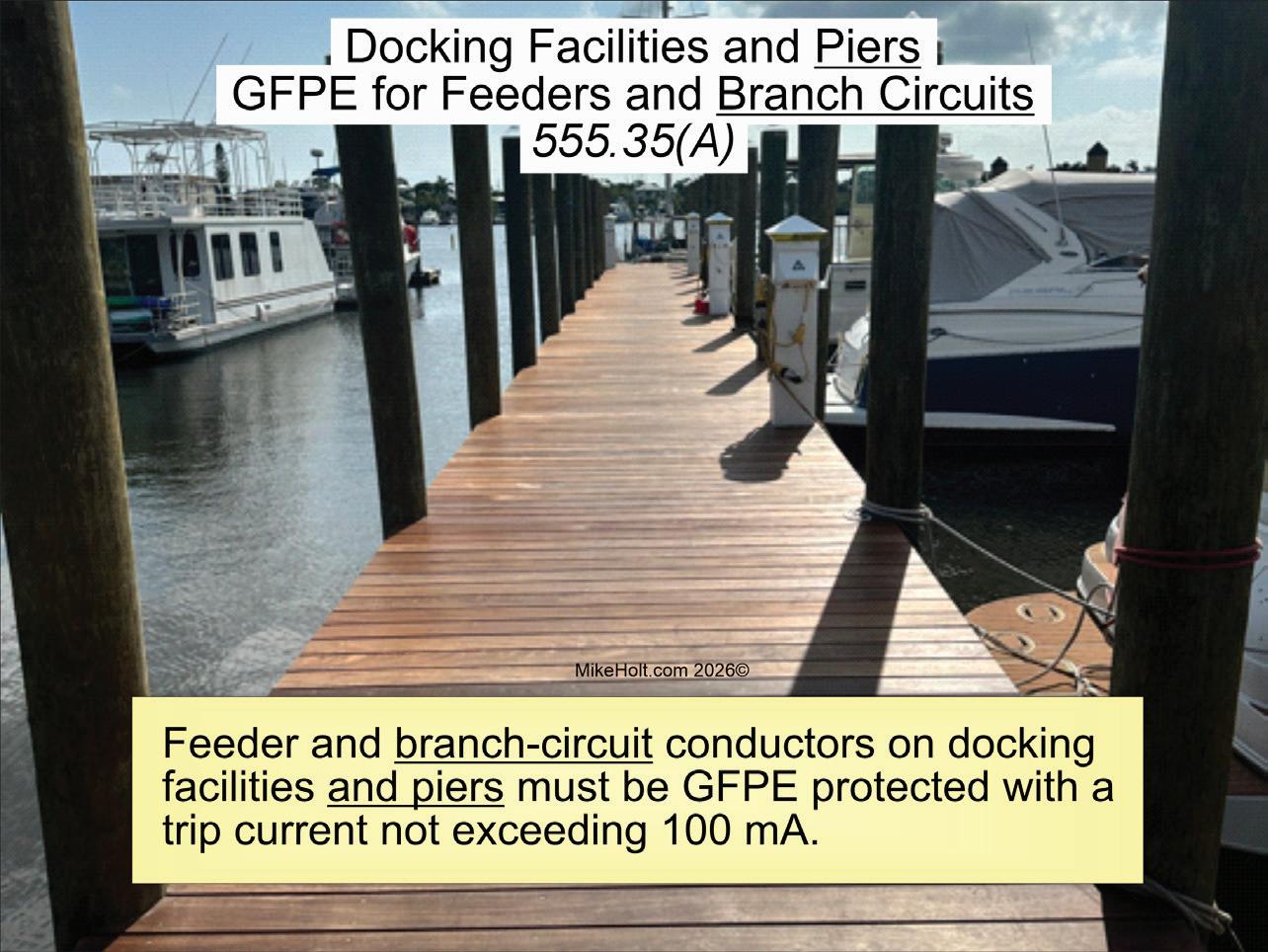
Section 555.35 GFPE and GFCI Protection
Analysis of the change:
The 2026 NEC expanded ground-fault protection of equipment (GFPE) protection on docks and piers. Revisions now require GFPE protection rated at 100mA or less for both branch circuits and feeders supplying docking facilities and piers. In short, all circuits supplying
structures over water must be GFPE protected to reduce the risk of electric shock hazards in marine environments.
New or revised Code language:
(A) Feeders and Branch Circuits. Feeder and branch-circuit conductors on docking facilities and piers must be GFPE protected with a trip current not exceeding 100mA, as shown in Fig. 21
CHANGE #21
NEW
Section 555.35 GFPE Performance Testing
Analysis of the change:
A new requirement specifies that GFPE protection systems must be coordinated and performance tested by a qualified person. Proper coordination of GFPE devices helps prevent nuisance tripping, ensuring a safe and reliable electrical system in marina environments.
New or revised Code language:
(F) Coordination and Performance Testing. GFPE protection systems must be coordinated and performance tested by qualified persons in accordance with the manufacturerʼs instructions. A written record of this testing must be made available to the authority having jurisdiction (AHJ).
CHANGE #22
NEW
Section 625.4
Qualified Persons
Analysis of the change:
A new Section requires that permanently installed electric vehicle power transfer equipment (such as Level 2

22.
or higher chargers) must be installed by a qualified person (as defined in Art. 100).
New or revised Code language:
Permanently installed electric vehicle power transfer system equipment must be installed by qualified persons (Fig. 22).
Note: See NECA 413, Standard for Installing and Maintaining Electric Vehicle Supply Equipment (EVSE) (Fig. 23).
Analysis of the change:
A new section requires permanent, visible markings on the outside of electric vehicle supply equipment (EVSE) enclosures. These markings show the voltage, number of phases, frequency, full-load current, and short-circuit current rating. Since EVSE installations allow field-adjustable current settings, these markings provide a quick way to verify proper circuit sizing and short-circuit rating before energizing the equipment.
New or revised Code language:
Electric vehicle supply equipment must have permanent field markings on the outside of the equipment enclosure that are visible after the installation, containing the following:
(1) Supply voltage, number of phases, frequency, and full-load
current for each incoming supply circuit
(2) Short-circuit current rating of the electric vehicle supply equipment based on one of the following:
a. Short-circuit current rating of a listed and labeled assembly
b. Short-circuit current rating established utilizing an approved method
Note: For an example of an approved method, see UL 2594, Standard Electric Vehicle Supply Equipment.
Author’s comment:
EVSE equipment can have the full load current adjusted in accordance with Sec. 625.42(B); therefore, this field marking is necessary to verify proper circuit sizing.
NEW
Section 625.43
Analysis of the change:
New emergency shutoff requirement for permanently connected EVSEs was
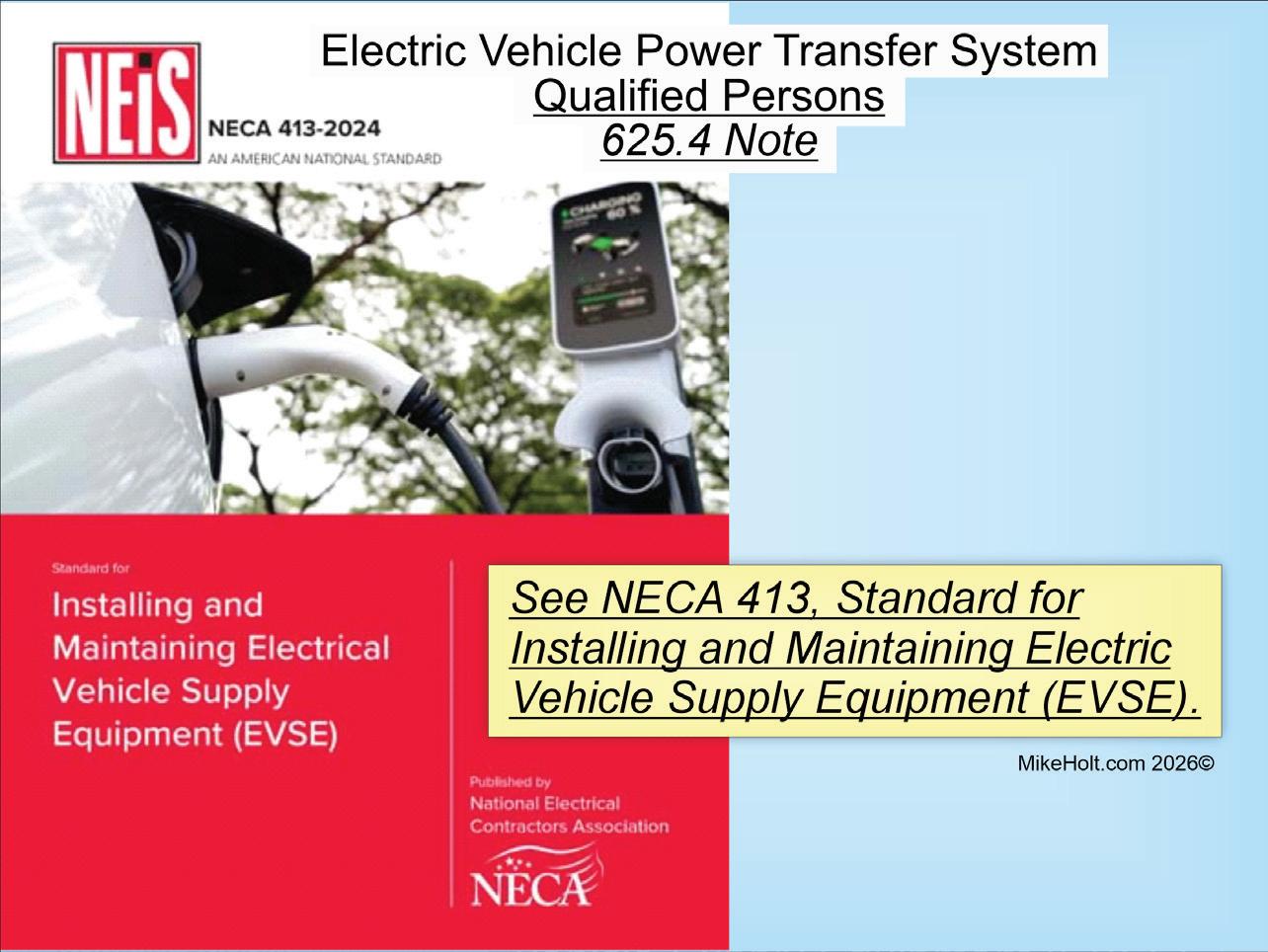
Fig. 24.
added for first responders. For other than one- and two-family dwellings, permanently connected EVSEs must have an emergency shutoff device installed
within sight — and located no closer than 20 ft and no farther than 100 ft — from the equipment. This provides a safe distance in the event of an electric
Many of the Articles in Chapters 7 and 8, which deal with limited-energy systems, have been consolidated into fewer Articles for better organization and consistency.
• Article 720. General Requirements for Limited-Energy Systems Wiring Methods and Materials. This new Article covers the general wiring methods and materials requirements for limited-energy system installations. It was created to consolidate the general rules for limited-energy systems, including Class 2, Class 4, power-limited fire alarm (PLFA), and communication systems. If you’re installing low-voltage wiring, be sure to review Art. 720 before roughing in cables to ensure a Code-compliant installation.
• Article 721. Power Sources for Limited-Energy Systems. This Article covers power source requirements for limited-energy system circuits.
• Article 722. Limited-Energy Cables for Power-Limited Circuits, FaultManaged-Power Circuits, Optical Fiber Circuits, and Communications Circuits. This Article contains the general requirements for limited-energy cables.
• Article 723. Raceways, Cable Routing Assemblies, and Cable Trays for Limited-Energy Systems. This Article covers the application and installation of raceways, cable routing assemblies, and cable trays for limited-energy systems.
• Article 742. Overvoltage Protection of Limited-Energy Systems. This Article covers the overvoltage protection requirements for limited energy systems installations.
• Article 750. Grounding and Bonding of Limited-Energy Systems. This Article covers the grounding and bonding requirements for limited-energy systems.
vehicle fire. The emergency shutoff device must be clearly marked to warn that the vehicle will remain energized — even after the EVSE is de-energized. With charging stations becoming more common, this rule ensures first responders and personnel have a quick, safe way to disconnect power in an emergency.
New or revised Code language:
(D) Emergency Shutoff.
(1) Emergency Disconnect. For other than one- and two-family dwellings, the emergency shutoff disconnect for EVSE and WPTE must:
(1) Be installed at a readily accessible location not less than 20 ft, or more than 100 ft, and within sight of equipment
(2) Be located within sight of the emergency shutoff
(3) Be marked “EVSE EMERGENCY DISCONNECT” and “WARNING: ELECTRIC VEHICLES WILL REMAIN ENERGIZED” in accordance with Sec. 110.22(A)
(4) Be a manual reset type
(5) Disconnect all phase conductors of the circuits simultaneously from the source of supply
(2) Equipment Disconnect Serving as Emergency Shutoff Disconnect. The equipment disconnect [Sec. 625.43(C)] is permitted to serve as the emergency shutoff disconnect — if the equipment disconnect complies with Sec. 625.43(D) requirements.
CHANGE #25
NEW
Section 625.44 Equipment Connections
Analysis of the change:
A new rules addresses when receptacles for EVSE must be listed for EVSE use. The most common point of failure in
• Article 245. Overcurrent Protection for Systems. This Article covers overcurrent protection requirements for nominal voltage systems rated over 1,000VAC or 1,500VDC.
• Article 265. Branch Circuits Over 1,000V [From Part II of deleted Art. 235]. This Article provides the general requirements for branch circuits of nominal voltage systems rated over 1,000VAC or 1,500VDC.
• Article 266. Feeders Over 1,000VAC, 1,500VDC Nominal. This Article covers the installation requirements, overcurrent protection requirements, minimum size, and ampacity of conductors for feeders of nominal voltage systems rated over 1,000VAC or 1,500VDC.
• Article 267. Outside BC and Feeders Over 1,000VAC, 1,500VDC Nominal. This Article covers requirements for outside branch circuits and feeders of nominal voltage systems rated over 1,000VAC or 1,500VDC.
• Article 268. Services Over 1,000VAC, 1,500VDC, Nominal. This Article covers installation requirements for service conductors and equipment for control and protection of services for nominal voltage systems rated over 1,000VAC or 1,500VDC. In no case can this Article apply to
an electrical system is at the connection point. All 30A, 50A, and 60A receptacles used for EV charging must be listed for EVSE use. This change addresses the growing issue of receptacle failures due to high temperatures under continuous loads — especially with cord and plug connections. Receptacles listed for EVSE use are specifically designed and tested for continuous load conditions, helping ensure safe and reliable charging over extended periods.
New or revised Code language:
(B) Hand-Fastened Equipment. Equipment that is hand-fastened
equipment on the supply side of the service point.
• Article 270. Grounding and Bonding of Systems Over 1,000VAC, 1,500VDC, Nominal. This Article covers general requirements for grounding and bonding of electrical installations for nominal voltage systems rated over 1,000VAC or 1,500VDC.
• Article 305. General Requirements for Wiring Methods and Materials. This Article covers wiring methods and materials for nominal voltage systems rated over 1,000VAC or 1,500VDC.
• Article 315. Medium Voltage Conductors, Cable, Cable Joints, and Cable Terminations. This Article covers the use, installation, construction specifications, and ampacities for Type MV medium-voltage conductors, cable, cable joints, and cable terminations. This Article includes nominal voltage systems from 2,001VAC to 35,000VAC and 2,001VDC to 2,500VDC.
• Article 495. Equipment Over 1,000VAC, 1,500VDC, Nominal. This Article covers the general requirements for equipment operating at nominal voltage systems more than 1,000VAC or 1,500VDC.
must be connected to the premises wiring system by one of the following methods:
(1) Nonlocking, 2-pole, 3-wire grounding-type receptacle outlet rated 125V or 250V, single-phase, in accordance with one of the following:
a. 15A or 20A
b. 30A or 50A listed for EVSE and WPTE use (Fig. 24 on page 55)
(2) Nonlocking, 3-pole, 4-wire grounding-type receptacle outlet
For a more in-depth look at the changes in this edition of the Code, this video package at www.mikeholt.com/productitem.php?id=7560 provides an even broader explanation of how to apply the NEC (Articles 90 through 480). Watch Mike and his video team dissect the changes and provide important feedback on how to apply the requirements in the field. 2026 NEC Video Training Package
rated 250V, 3-phase, in accordance with one of the following:
a. 15A or 20A
b. 30A, 50A, or 60A listed for EVSE and WPTE use
(3) Nonlocking, 3-pole, 4-wire grounding-type receptacle outlet rated 125V/250V, single-phase, in accordance with one of the following:
a. 15A or 20A
b. 30A, 50A, or 60A listed for EVSE and WPTE use
Author’s comment:
There are concerns in the industry about the failure of the standard-grade (residential) receptacle used for the connection of EV equipment. Consideration should be given to the use of receptacles that are specifically designed for EV equipment use.
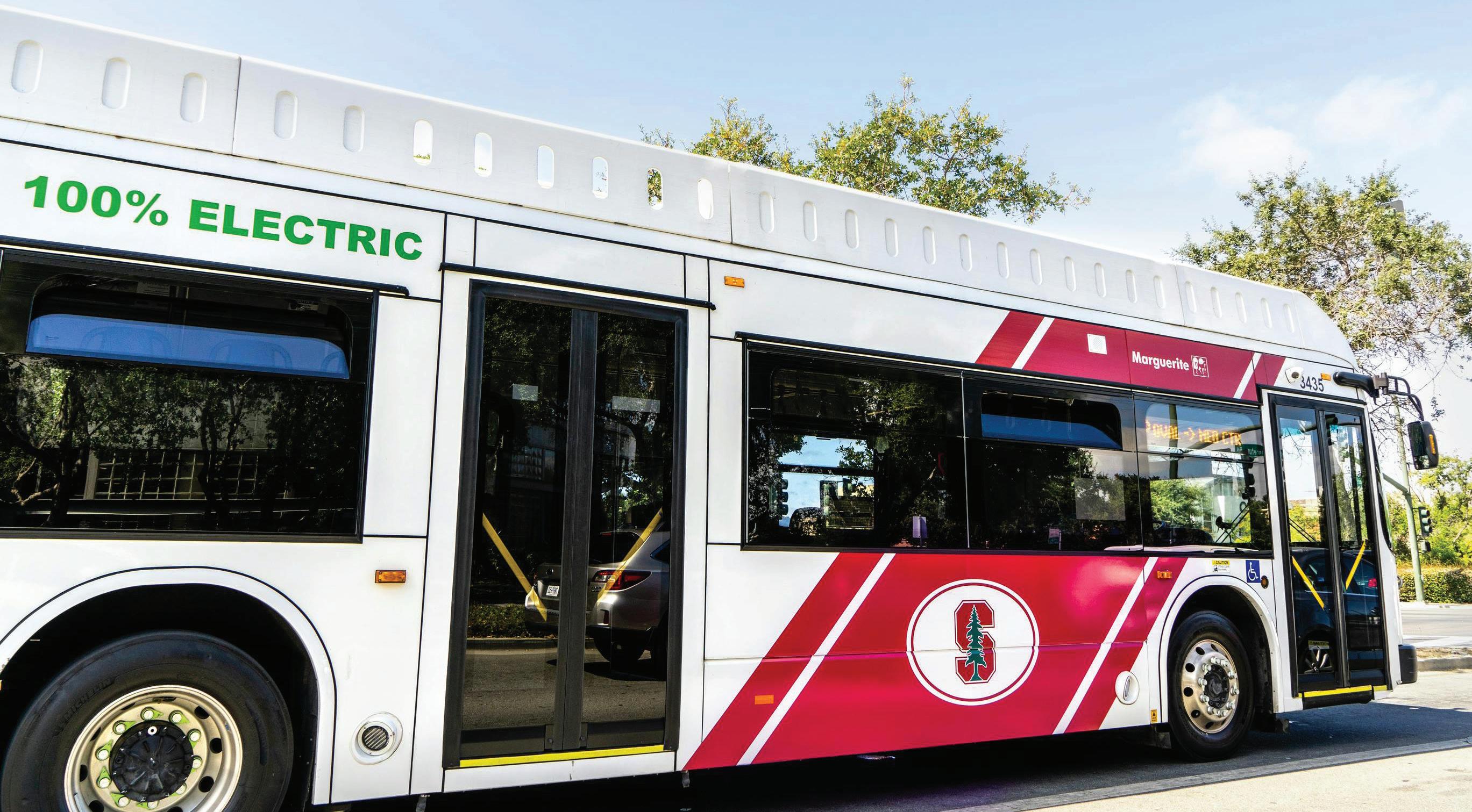
School, transit, and airport bus fleets are slowly electrifying. Wireless charging, vehicle-to-grid systems, and as-a-service business models are among the innovations aimed at overcoming multiple roadblocks.
By Tim Kridel, Freelance Writer
At first glance, buses seem like a great fit for electrification. Whether they’re for schools, public transportation, or airport shuttles, buses follow a set route and schedule, unlike other fleets, such as rental cars and package delivery trucks. That predictability helps with determining battery sizes, charging locations and types, grid impact, and whether there’s a business case for adjunct systems such as battery storage and solar.
Sustainability is another obvious reason why governments, utilities, and even electrical equipment manufacturers are joining fleet owners in funding electric vehicle (EV) bus projects.
“Both local and state agencies have goals of achieving a 100% zero-emission bus fleet by 2040, and some even earlier,” says Anthony E. Mann, CEO of the E-J Group, whose recent projects include the MTA New Jamaica Electric Bus Depot in New York City, as shown in the Photo on page 58. “We are seeing these agencies be proactive in this approach, especially with major transportation hubs, school districts, and bus companies. New York City is transitioning 5,700 buses to zeroemission electric models by 2040, and New Jersey Transit is aiming for a 100% electric bus fleet by 2032.”
Seven to 15 years might seem like a long way off until you consider some of the challenges to large-scale bus
electrification, starting with transmission lines and substations.
“The demands are pretty big,” says Rajiv Singhal, who leads the zero emissions transportation team at 1898 & Co., Burns & McDonnell’s consultancy subsidiary. “Battery size averages more than 450kWh. If you have 10 buses, that’s 4.5MW. That’s where the challenges start.”
For electrical contractors and design firms, substations are an example of how EV bus revenue opportunities go beyond the obvious ones of designing and installing charger networks.
“When we did work for the St. Louis [Missouri] Metro, we had to build a substation for Ameren to support that power at their depot,” Singhal says.
Of course, building a substation can take years between acquiring land, zoning approval, procuring equipment, and construction. Smart charging systems can help by spreading the load around, either until the grid can be upgraded or as a long-term solution.
“Dynamic charging moves power available to the bus that needs it most to prioritize bus needs, [so the fleet is] not as big a burden on the grid,” Mann says. “Charging buses on non-peak hours [also helps] to not overburden the grid.”
Grid constraints are also an example of how the road sometimes goes both ways via vehicle-to-grid (V2G) charging systems.
“These allow buses to return energy to the grid during peak demand periods,” Mann says.
With some types of EV buses, the funding source requires V2G infrastructure. That gives utilities an even bigger role in those projects.
“The EPA grant for school buses really drove that market pretty fast last year,” Singhal says. “They have to be bidirectional to qualify for the grant. Some utilities are doing pilots. Baltimore Gas and Electric applied for 200 buses and got approval for 25. They want to run pilots for bidirectional. Dominion Energy in Virginia has been running a pilot for a few years for 50 school buses.”
School buses are a major opportunity simply because there are so many of them.
“There are three big names in the school bus market: Blue Bird, International, and Thomas,” Singhal says. “It’s a huge market in terms of the number of buses on the road — about half a million.”
Their usage is also conducive to electrification.
“They’re definitely a good use case for electrification based on small routes,” Singhal says. “[After] morning and afternoon shifts, they can easily charge, so the batteries don’t have to be large.”
But even with government and utility funding, upfront costs and the potential for surprise costs later on are two common roadblocks. Hence, the rise of as-a-service business models. For example, the Clean Bus Solutions joint venture between Blue Bird and Generate
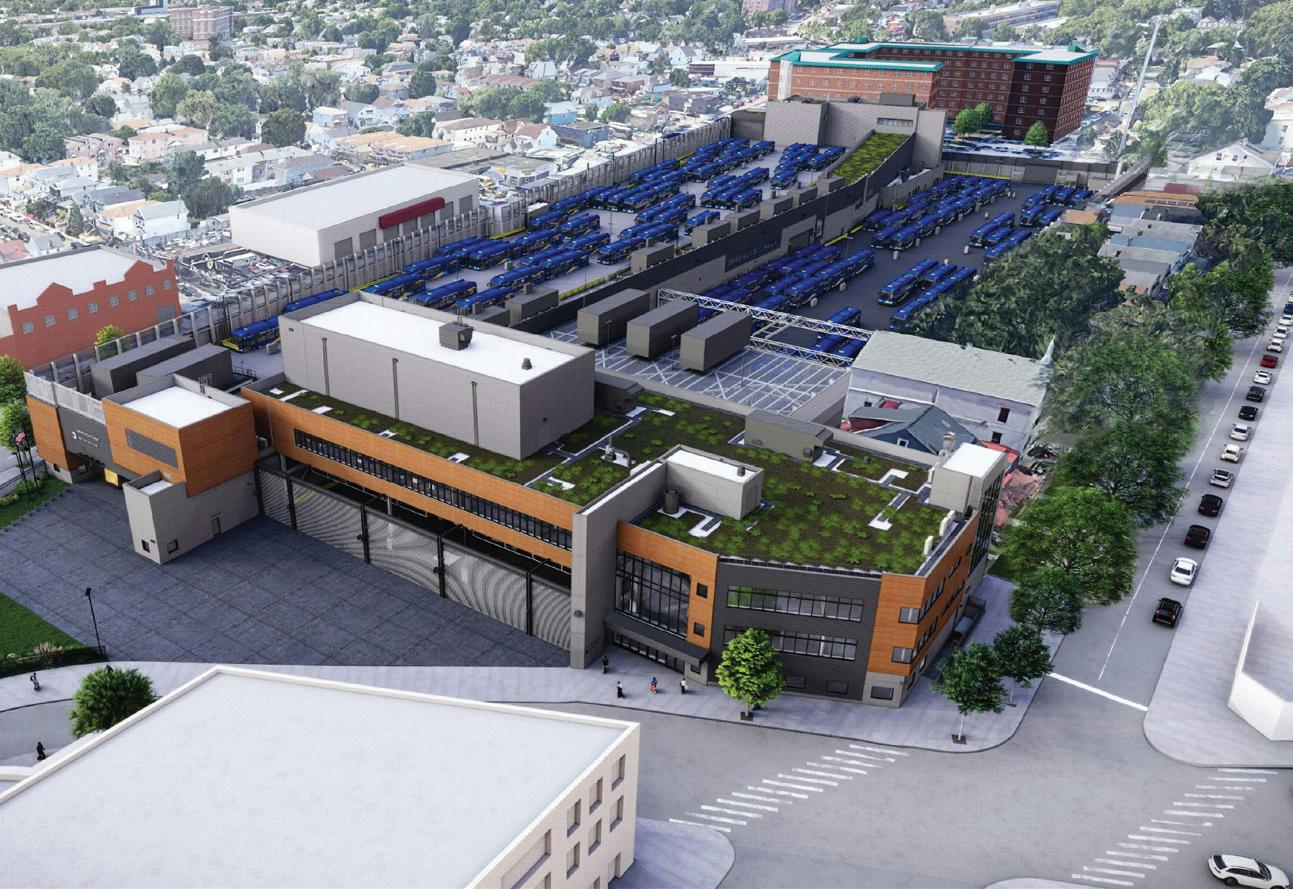
The MTA is reconstructing and expanding the existing Jamaica Bus Depot in Queens, N.Y. This project will modernize the depot and provide the facilities needed to operate, maintain, and store up to 300 buses, according to E-J Group. It will also create facilities to support the MTA’s first fully electric bus fleet and accommodate new bus service demands that will improve bus circulation throughout Queens.
Capital uses a “fleet-as-a-service” business model: School districts and other operators pay a flat monthly fee for a turnkey package that includes buses, site assessment, charging infrastructure, telematics, demand-management software to control electric usage, and even lining up grants.
Many school districts contract out bus service rather than owning a fleet. For electrification to make business sense, those operators would need a contract long enough to amortize the upfront cost of building a depot’s worth of charging infrastructure. The local utility also would want a long-term commitment.
“The financials on that pan out only at 15-years-plus time frame,” Singhal says. “No one wants to sign a contract that long unless there is some sort of power purchase agreement for 25-plus years.”
The transit market has its own set of dynamics.
“There are two major players: New Flyer and Gillig,” Singhal says. “Then Proterra came into the picture, which was only electric buses, and they filed Chapter 11. Every year in the transit
market, there’s demand for about 4,000 buses. New Flyer goes after the large transits, and Gillig goes after the smaller transits. That’s the market division. They sell about 2,000 buses each [across] diesel, CNG, whatever.”
Some transit projects are large, such as Montgomery County, Maryland’s David F. Bone Equipment Maintenance and Transit Operations Center, which aims to be the country’s largest renewable energy-powered transit depot and the largest transit depot microgrid, with:
• 4.84 MWDC of rooftop and canopy solar
• 2MW/6.88MWh battery storage
• Up to 2.25MW of charging capacity
• Up to 2MW of V2G power going back
The Bone facility broke ground in 2024 and is the county’s second microgrid after the Brookville Smart Energy Bus Depot that opened in 2022. Both facilities are backed by AlphaStruxure, a joint venture between the investment firm Carlyle and Schneider Electric, as well as Pepco, the local utility. Bone is also an example of how “electric” doesn’t necessarily mean batteries. Most of its anticipated 200 electric buses will be powered by hydrogen fuel cells because “they have a greater range versus battery
electric buses and can thus support longer bus routes,” the county says.
“We are seeing some emergence of hydrogen fuel cell buses,” says E-J’s Mann. “This will lead to the need for hydrogen changing stations at these bus depots.”
Airport shuttle fleets currently are the smallest market opportunity.
“Generally, airports don’t own their shuttles,” Singhal says. “Mostly, they are third-party contractors. I’m not seeing a lot of action at airports right now on the terminal side.”
One notable exception is Kansas City International Airport, which is also the first in the country to have wireless induction charging for its fleet that shuttles passengers between the terminal and long-term parking.
“Our customers love them,” says Joe McBride, communications manager. “They’re quiet. They’re cleaner. It’s a swell passenger experience.”
Kansas City’s buses use conventional plug-in chargers at the depot, including when drivers go on breaks and lunch. But the rest of the time, they charge at each terminal stop via a plate built into the roadbed.
“The vehicle rolls over the pad, aligns, and we’re passing power in less than 2 seconds,” says Jeremy Siegel, strategy and energy director at InductEV, which provided Kansas City’s charging infrastructure and upgraded the airport’s fleet to support induction. “The driver does not have to leave the vehicle to do anything.”
That hands-free design highlights one of induction’s benefits — no cable to remember to plug in or disconnect before driving off.
“There’s also a maintenance component to it: nothing to break, nothing to hit, nothing to necessarily wear out,” Siegel says. “Maintenance is essentially a visual inspection of the pads on the vehicles every six months, servicing the cabinet fan, which is the only moving part, and adding coolant to the system.”
Roadbed chargers also could help projects get approved faster compared to the pantograph systems that some fleets use.
“It’s much more straightforward and less obtrusive when you’re trying to get approvals from planning boards or
architectural review committees,” says Greg Brenner, managing director at WB Engineers+Consultants, which has been the engineer of record on several InductEV installations.
Another major benefit is that induction spreads the charging load around both geographically and by time of day. This approach can help with electrification because a project’s cost and timeline no longer hinge on the grid capacity available at an airport’s depot.
“As opposed to charging, say, 50 buses in a depot with 50 chargers overnight, think about charging those 50 buses with five chargers scattered along their routes,” Siegel says. “They essentially charge in ‘sips’ at the normal stops, turn arounds, things like that. With 5 to 7 minutes an hour, you can generally maintain a state of charge on the vehicle throughout the day.”
This also affects battery longevity and size.
“You’re operating in a fairly small state of charge — say 40% to 70% — and not deep cycling, so the batteries last a lot longer, often beyond the life of the vehicle,” Siegel says. “Battery replacement is a major capital expenditure. You can also potentially do smaller batteries since you’re charging along the route and don’t need a vehicle to do the absolute [maximum] range over the course of the day.”
Another way that frequent access to charging saves capex is by reducing fleet size. Those savings could help some projects get the green light.
“When you have a single vehicle that can maintain a continuous loop without stopping to recharge or going offline while they swap out another vehicle, it’s a big game changer,” Brenner says.
InductEV also serves the transit market. Whether it’s airport shuttles or public transportation, one key design consideration is the number of induction charging pads around a route and the typical dwell time at each. That’s one lesson learned in Kansas City, which implemented induction charging at a brand-new terminal that has a significantly different route and schedule than the three terminals it replaced.
“We haven’t really utilized it to the potential that we thought,” says Aaron Kaden, the aviation department’s fleet asset superintendent. “Unfortunately,
the dwell time for the bus to sit at the new terminal is not like it was at the old terminals. We were going to try to use it so that we maintained a 65% to 85% state of charge. But with the buses only sitting there for maybe a minute, we’re not even getting a 1% state of charge [increase].”
Regardless of the power source and how it gets to the bus, another electrification challenge for fleet owners is finding enough qualified people to maintain everything.
“The number of parts are less when you compare a diesel bus to an electric bus, but it’s high voltage,” says 1898’s Singhal. “So instead of a mechanic, you need more of an electrician.”
Some automotive trade schools have launched EV programs, but it’s going to take time to meet demand. Bus owners are also competing with other types of fleets, such as rental vehicles, local delivery, and long-distance trucks as well as dealerships that need to service the passenger vehicles they sell and lease.
“I don’t know how more involved we’re going to get with EVs at this point, just because we are struggling to get training for the technicians to fix the buses,” Kaden says. “I think there needs to be more companies that offer training for technicians on EVs. Once that happens, it’s going to make it a lot easier for entities to repair their own stuff.”
It’s a stretch to see electrical contractors expanding into maintenance to fill that gap and turn it into an additional revenue stream. But there could be systems integration opportunities for clients with multiple suppliers of charging infrastructure, buses, and other systems. For fleet owners, a multivendor environment might seem like a smart move in light of bankruptcies such as Proterra and Lion Electric.
“If I’m a large transit, I don’t want to get locked into one vendor,” Singhal says. “Lots of interoperability questions come into play.”
Tim Kridel is an independent analyst and freelance writer with experience in covering technology, telecommunications, and more. He can be reached at tim@timkridel.com.

The SACE Emax 3 is designed to address increased concerns about grid stability, cybersecurity, and the surging power needs of AI in data centers by minimizing the risk of power outages. Featuring accurate power sensors and data analytics, the Emax 3 collects and analyzes real-time data from the electrical system, including power usage, system health, and environmental conditions such as temperature. This information is shared remotely or on the device’s touchscreen, offering users real-time insights, warnings, and recommendations for precise maintenance. The Emax 3 air circuit breaker possesses a security level 2 IEC 62443 cybersecurity certification and a fully integrated arc flash detection system to enhance safety and reliability.
ABB

The AMP SECURE contemporary flood lights are offered in two sizes and feature selectable lumen output, selectable color temperatures, universal voltage (120V277V), 0V-10V dimming, integrated dusk-to-dawn photocontrol, and durable die-cast aluminum construction. The flood lights are offered in 80W and 35W models and designed for both wall and ground mounting. The luminaires feature a ½-in. NPS pipe thread at the base for ground mounting and a decorative mounting plate for wall applications. The 80W flood light can be mounted from 16 ft to 30 ft, while the 35W model is suitable for heights from 10 ft to 20 ft. The selectable lumen switch offers choices of 2,500 lm, 4,000 lm, or 5,000 lm for the 35W model and 6,500 lm, 9,300 lm, or 12,000 lm for the 80W model. The selectable color temperature options include 3,000K, 4,000K and 5,000K.
AMP Lighting
The Chloride CH2-G2 series is a highperformance single-phase inverter system designed to meet critical power requirements, offering a power range of 1.0kVA/kW to 2.8kVA/KW. Engineered for reliability, this system is UL924 listed and compatible with LED, fluorescent, incandescent, and halogen lamp loads, while providing a standard runtime of 90 min. Equipped with advanced features and configurable options, the CH2-G2 series supports multiple communication protocols.
Signify
The Ex9VF7 variable-frequency drive (VFD) delivers precise speed and torque control from 0.5 hp to 250 hp. The product has a compact design, sensorless vector control, 150% overload rating for 60 sec, and an operational voltage range from single-phase 110V to 3-phase 600V. The Ex9VF7 is cUL/UL certified for models from 0.4kW to 185kW, ensuring North American compliance. Ex9VF7’s operational voltage ranges from single-phase 110V to 3-phase 600V.
NOARK Electric

The Reclaimer wedge boot is designed to move seamlessly from the job site to everyday life. These boots feature fullgrain waterproof leather and a membrane that keeps water out. The full grain leather uppers are durable, protective, and abrasion resistant. The product features slip-resistant (SR) soles to reduce the risk of slips on the job and electrical hazard protection (ASTM F2413-24). The boots also offer a molded EVA foam footbed for underfoot comfort, a durable rubber outsole, and soft, breathable nylon mesh. Caterpillar
The XUR solution is an expandable riser requiring no cutting or gluing, easing the installation of ground electrical cable to panel and meter boxes. The new expandable utility riser can withstand extreme temperature changes (operable in temperatures of -40° to +230 °F) and is protected against expansion and contraction from high variations. The product is heightadjustable, impact- and UV-resistant, and can be made and shipped with customerspecific transitions.
Champion Fiberglass

The ultra fast surge arrester (UFSA) is a medium-voltage grid hardening and protection device designed to shunt current that has been induced into conductor(s) from a directed energy attack or E1 transient EMP event. UFSAs have hairtrigger characteristics, operating within 6 ns until the E1 event and current is safely quenched to earth, protecting the point of supply, grid interface, and/ or utilization equipment. The compact devices are warranted for 10 years and 1,000 events.
NW Signal Maintenance
The P66 is a safe, high-powered, and durable electrical connection engineered for mobile electrification in harsh and demanding industrial environments. The product is rated to deliver up to 660A at 1,100VAC and 1,500VDC and features IP66/IP67 ingress protection, IK10 impact resistance, and multiple built-in safety and control options, along with flexible installation configurations. It features a magnetic reed switch pilot circuit, cord-to-cord connectivity, straight (180°) and right-angle (90°) configurations, and a reversible drawbar mechanism.
MELTRIC
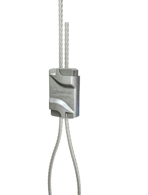
The HangPro No. 2 supports up to 120 lb with a 5:1 safety factor and allows for postload adjustment, giving installers flexibility even after the load is applied. Its patented cable entry gate ensures correct cable alignment for consistent, Code-compliant installations and improved on-site safety. Each unit is batch-coded for full traceability and has an ergonomic design with accessible buttons.
Gripple

GreenConnect delivers a simple lighting control solution by adding wireless control to virtually any switching or dimming load, according to the company. Compatible with various lamp luminaires and load control devices, GreenConnect offers a scalable and flexible wireless solution with no complex wiring, room controller, hub, app, or factory commissioning required. The product utilizes push-to-pair (P2P) technology that features a scalable platform. It features a reliable 2.4GHz wireless mesh network. The system includes wireless load controllers and wall stations for switching, 0V-10V and forward phase dimming. Additionally, GreenConnect offers wireless battery-powered switches and dimmers for wire-free and multi-location control wireless-controlled receptacles with downstream control, along with wireless battery-powered PIR sensors with integrated photocells.
Leviton
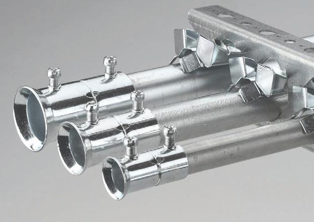
The CADDY flared traditional couplers are designed to reduce the number of steps required for installing conduit racks. The integrated flare helps align each piece of conduit to easily join and install prefabricated conduit racks. This design allows the coupler to simply slide over the conduit and have visual confirmation of correct insertion depth through the center viewport.
nVent

The humidity sensor switch detects humidity levels and activates the exhaust fan when needed, thus reducing moisture, mildew, and mold in any bathroom space. The device is compatible with a 3A, 1/10-hp fan. The XactSense humidity sensor switch uses advanced signal processing to determine the optimal time to activate the fan. This low-effort, highimpact remodel device delivers a simple solution for homeowners, minimizing energy consumption and maximizing efficiency.
Lutron
By Mike Holt, NEC Consultant
All questions and answers are based on the 2023 NEC.

Q1: Where may be present in an agricultural building, enclosures and fittings shall have corrosion resistance properties suitable for the conditions.
a) wet dust or excessive moisture
b) corrosive gases or vapors
c) other corrosive conditions
d) any of these
Q2: Conductors in Art. 300 shall be of copper, aluminum, or copper-clad aluminum, unless otherwise specified. Copper-clad aluminum conductor material shall be
a) identified for the use
b) listed
c) indicated as suitable
d) approved
Q3: Panelboards shall be mounted in cabinets, cutout boxes, or identified
enclosures, and, where the available fault current is greater than , the panelboard and enclosure combination shall be evaluated for the application.
a) 5,000A c) 12,500A
b) 10,000A d) 22,500A
Q4: In ungrounded systems, electrical equipment, wiring, and other electrically conductive material likely to become energized shall be installed in a manner that creates a low-impedance circuit from any point on the wiring system to the electrical supply source to facilitate the operation of overcurrent devices should a(an) fault from a different phase occur on the wiring system.
a) isolated ground
b) second ground
c) arc
d) high impedance
Q5: Where insulated conductors are deflected within a metal wireway, the wireway shall be sized to meet the bending requirements corresponding to per terminal in Table 312.6(A).
a) one wire c) three wires
b) two wires d) four wires
Q6: A box or conduit body shall not be required for splices and taps in conductors and cables as long as the splice is made with a splicing device that is identified for the purpose.
a) direct-buried
b) exposed
c) concealed
d) none of these
See the answers to these Code questions online at ecmweb.com/55324645.

March 18-19, 2026
Lodi, CA


April 8-9, 2026
Anaheim, CA
NORTHWEST
April 29-30, 2026
Portland, OR


By Russ LeBlanc, NEC Consultant
All references are based on the 2023 edition of the NEC.
Waves in rigid PVC conduit are not the kind of waves you expect to see at the beach, but the lack of expansion fittings and too few conduit clips have caused this conduit run to become a wavy mess. Table 352.30(B) requires the maximum spacing between supports for rigid PVC conduit to be limited to 3 ft for conduits of trade sizes 1/2-in. through 1-in. The clips used to support this conduit run are spaced way too far apart. That one violation by itself can cause the conduit to droop and sag. Now, add the lack of an expansion fitting as required by Sec. 352.44(A), and the sagging and drooping problem increases dramatically.
Long, straight PVC conduit runs like this one can experience surprisingly large changes in length due to thermal expansion and contraction. For example, according to Table 352.44(A), a 100-ft run of PVC conduit could

experience a length change of approximately 4 in. as the seasons change from a cold winter day to a hot summer day and back again. That is an amazing
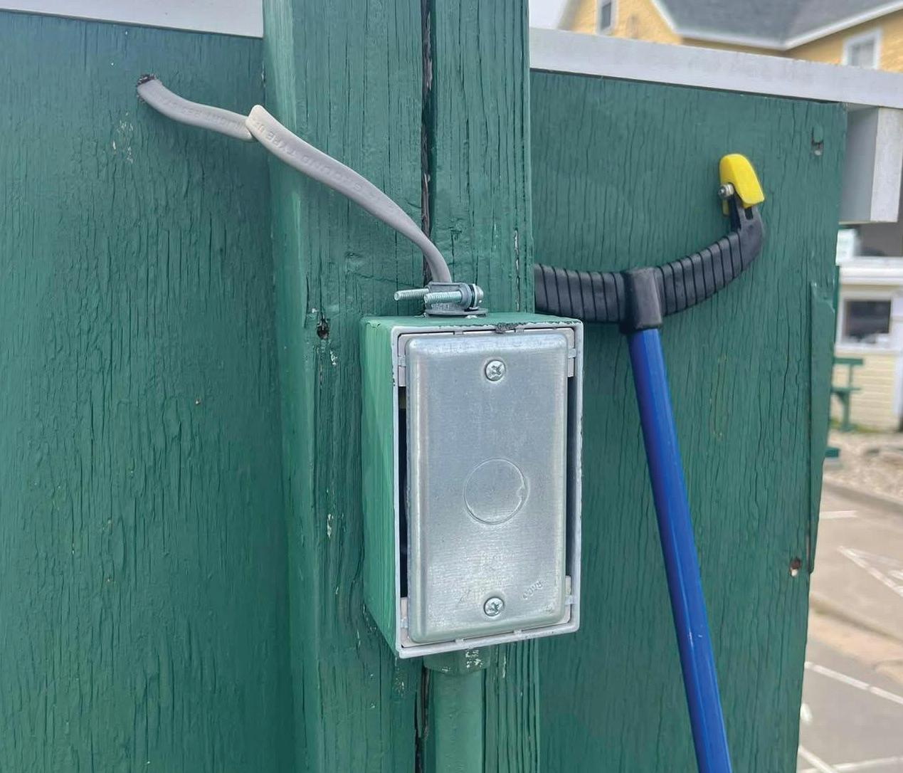
change in length and could potentially cause the conduit run to self destruct if expansion fittings are not used to accommodate that length change.
I spotted this wiring on the back of a parking lot sign. Installing UF cable outside in a wet location where it is exposed to the sun is permitted by Secs. 340.10(3) and 340.12(9) if the UF cable is identified as being sunlight resistant. This UF cable is fine for this application, but the cable connector and box cover are another story.
For boxes and fittings installed in wet locations, Sec. 314.15 requires the boxes and fittings to be listed for wet locations and “be placed or equipped so as to prevent moisture from entering or accumulating within the box, conduit body, or fitting.” The NM cable connector on the top of the box is not listed for use in wet locations and does not prevent moisture from entering the box. The type of box cover and the lack of a cover gasket are also problematic. They do not prevent moisture from entering the box. An easy fix for a Code-compliant installation here would be to replace the NM cable connector with a compression-type UF cable connector and also replace the box cover with a gasketed, wet location-rated cover.
To place a display ad (1/6 page or larger), call the Advertising Sales Representative for your area.
Vice President
Mike Hellmann
Andover, MA • (978) 289-0098
E-mail: mhellmann@endeavorb2b.com
Western U.S. & Western Canada
Ellyn Fishman | Key Account Manager (949) 239-6030
Email: efishman@endeavorb2b.com
Northeast U.S. & Eastern Canada
David Sevin | Account Manager 24 Houghton Street • Barrington, RI 02806 (401) 246-1903
E-mail: dsevin@endeavorb2b.com
Midwest, Southeast,and Southwest
Jay Thompson | Account Manager 7450 W. 130th Street, Suite #210
Overland Park, KS 66213 • (913) 967-7543
E-mail: jthompson@endeavorb2b.com
Marketplace/Inside Sales
Steve Suarez | Media Account Exec 7450 W. 130th Street, Suite #210
Overland Park, KS 66213 • (816) 588-7372
E-mail: ssuarez@endeavorb2b.com
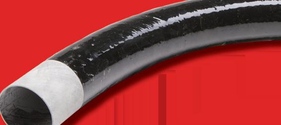


By Russ LeBlanc, NEC Consultant
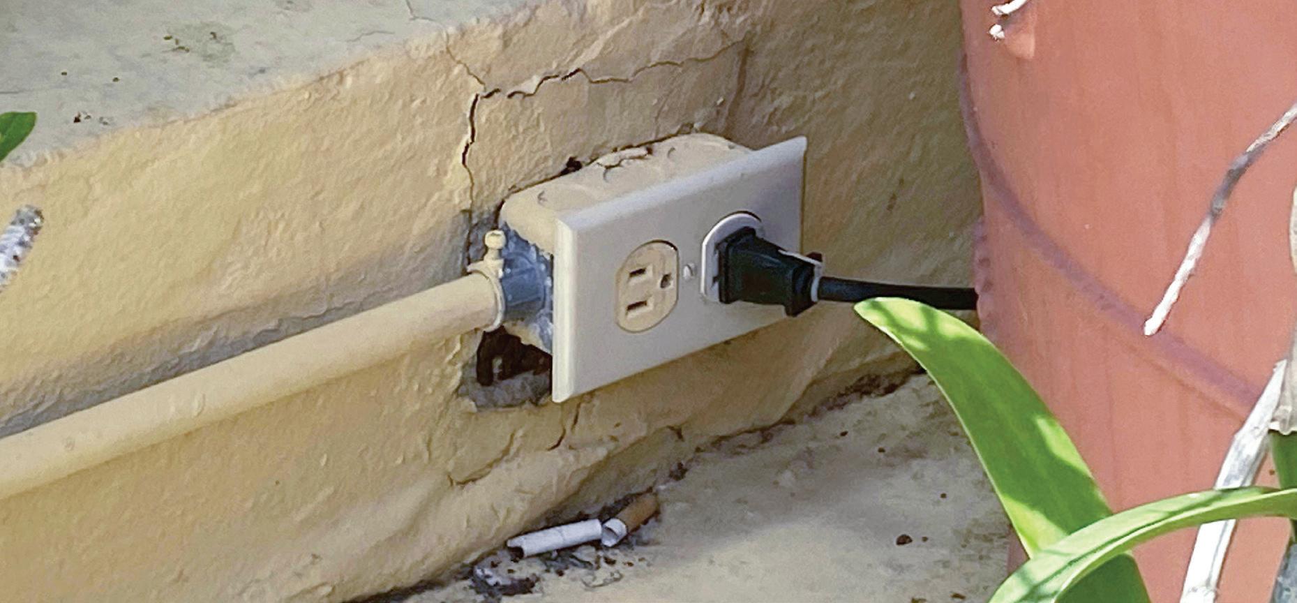
How well do you know the Code? Think you can spot violations the original installer either ignored or couldn’t identify? Here’s your chance to moonlight as an electrical inspector and second-guess someone else’s work from the safety of your living room
or office. Can you identify the specific Code violation(s) in this photo? Note: Submitted comments must include specific references from the 2023 NEC.
Hint: The weather forecast calls for rain.
Using the 2023 NEC, correctly identify the Code violation(s) in this month’s photo — in 200 words or less — and you could win a $25 Amazon gift card. E-mail your response, including your name and mailing address, to russ@russleblanc.net, and Russ will select one winner (excluding manufacturers and prior winners) at random from the correct submissions. Note that submissions without an address will not be eligible to win.

Our winner this month was Moshe Fisch, a project manager for MR Electrical Service, Linden, N.J. Moshe correctly cited Sec. 300.4(G), which requires raceways containing 4 AWG or larger insulated circuit conductors to have the conductors protected where these conductors enter a cabinet, box, enclosure, or raceway. This protection must be provided before the installation of conductors. The conductors can be protected by an identified fitting providing a smoothly rounded insulating surface, a listed metal fitting that has smoothly rounded edges, separation from the fitting or raceway using an identified insulating material that is securely fastened in place, or threaded hubs or bosses that are an integral part of a cabinet, box, enclosure, or raceway providing a smoothly rounded or flared entry for conductors. Several of the raceways in this photo have no protective fitting or bushing installed.


Stop chasing parts all over town and half the internet. When jobs call for electrical, plumbing, and HVAC parts, place one order and knock out your next job from start to finish with SupplyHouse.


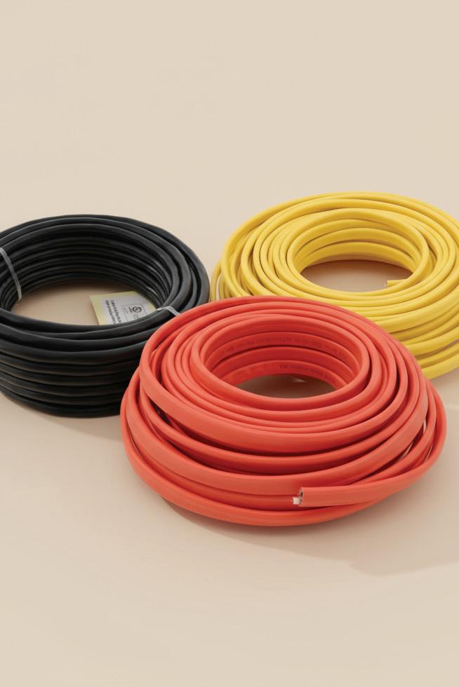

No burn-through eliminates elbow repairs
Light weight facilitates a smooth, safe, cost-effective installation
Low conduit coefficient of friction makes cable pulling a breeze


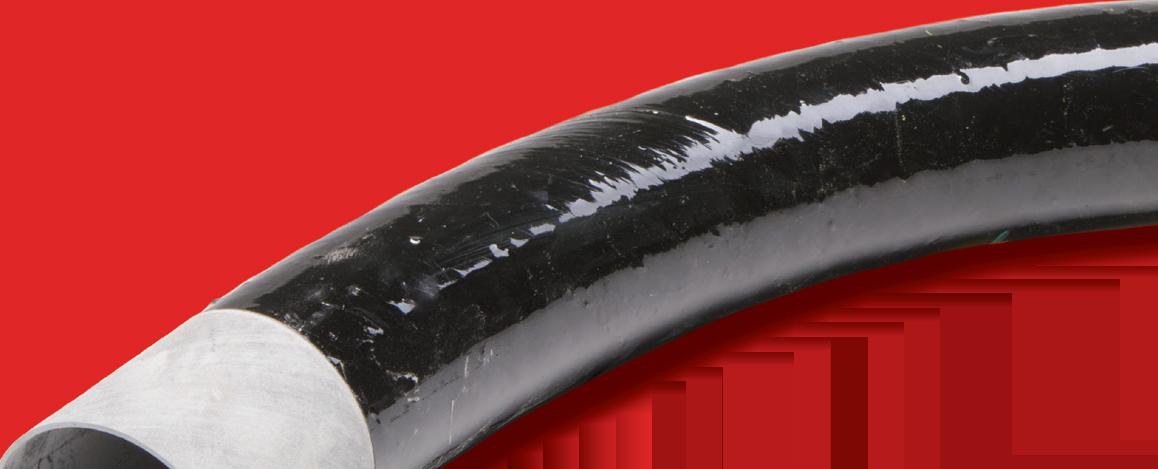


110 °C temperature rating makes cable ampacity adjustment factors less severe
Durable and corrosion-resistant for lower total cost of ownership