


Finding your final diagnosis is simple – trust your process, look at all the angles, change your approach if needed.
By Emily Markham, Editor Emily@VehicleServicePros.com
aving a standard diagnostic testing process in your shop does three things:
• It keeps everyone on the same page – everyone is following the same initial steps and performing the same basic tests.
• It helps prevent misdiagnosis –with everyone following the process put in place, no technicians will be cutting corners or making assumptions about the vehicle.
• It makes conversations with customers easier – you can tell them exactly the process that is taking place to examine their vehicle.
But what happens if you’re following the steps, performing all the right tests, and things just don’t seem right? In our first article, Chris Martino walks us through a repair that really put his diagnostic process to the test.
“Trust your process,” Martino says. “Don’t deviate even though something may be unbelievable. These vehicles are only machines and follow simple rules when broken down to their base systems.”
Once you’ve gone through your initial process, you may have a diagnosis in mind. However, even if you do think you have the answer to why a vehicle was towed into your shop with a dead battery, your conclusion may not be right.
In our second article, Brandon Steckler urges you to open your mind
to the many possibilities of what may have caused that vehicle to end up in your shop. Going back to the example of the vehicle with the dead battery, Steckler creates a list of questions to ensure you’re looking at this problem from every angle.
• Is the battery just old and expired?
• Is there a parasitic drain present, killing the battery?
• Is the alternator charging?
• If not, why? Is there a voltage drop elsewhere in the battery charging circuit?
“I always choose to take the diagnostic path that yields me the most information for the least amount of time or energy invested,” Steckler explains.
Similar to Steckler’s view of diagnosing from different angles, our final article looks at the similarities and differences that come with making the same repair on two different vehicle types – an internal combustion engine vehicle and an electric vehicle.
Though some parts of your process may stay the same, Craig Van Batenburg notes that there will come a point where the knowledge from your “12V brain” won’t match up with the knowledge from your “high-voltage brain” and you’ll have to deviate your diagnostic approach.
As you flip through this guide, we hope you find ways to strengthen and improve your diagnostic process.

We’ve all encountered that vehicle that comes from another shop. The one where it seemed every time the right decision could have been made, the technician turned left.
By Chris Martino

Today, I want to tell a different kind of story. It all started as any other day. I was on the road doing some mobile diagnostics and programming when I received two text messages from a shop I do some work for occasionally. The messages were screenshots of some codes and pictures of some scan data (Figures 1 & 2).
Looking at these pictures, I could see that the vehicle in question was a Land Rover that had codes for Cylinder No. 5 injector circuit — open, and a Cam Position Sensor B Circuit range/ performance code.
This was followed by a phone call
from the shop owner. The vehicle was a 2018 Land Rover Discovery owned by a childhood friend of his. According to the shop owner, the vehicle owner noticed the vehicle was running poorly and decided to get it scanned. The shop he took it to made the decision the timing was off and recommended the engine be rebuilt. The vehicle owner approved the repair, and the shop sent the vehicle to a local engine rebuild shop.
The truck was at that rebuilder for a few weeks. When the vehicle owner called to check in, the rebuild shop relayed that they were having issues making the truck run correctly. They scanned it and sent the screenshots to
the vehicle owner. The vehicle owner sent them to his friend, and then they made their way to me.
The repair shop (my client) then asked me to go to the engine rebuild shop and give them some direction — as they seemed lost with this Land Rover.
These vehicles need special tools to set the timing chains up correctly, and not using them can cause the engine to be out of time. I told the shop that I would go and check cam/crank correlation with a scope to verify timing and go from there.
I arrived at the engine rebuild shop. The vehicle was outside and someone was working on it. I could see the tech had the spark plugs all out of the driver‘s side bank. This was going to be tough to work on. I started speaking with the tech and more of the story began to emerge.
After the engine rebuild, they had the “camshaft code” that would not clear and the fuel injector No. 5 code that would not clear. When they inspected the No. 5 injector, they found it damaged and the internal wiring was exposed. They replaced the injector, but nothing had changed.
They asked me if I could check the operation of the cam sensor because they replaced it, but the code would not clear. I happily hooked up my Pico 4425a digital storage oscilloscope, removed the fuel control fuse, and cranked the vehicle. I saw a healthy pattern. I explained to them that this only meant the cam sensor worked. It won’t tell me the camshafts are in time unless I reference all the sensors.
The tech also stated that it was still running rough, and he could not get rid of the injector code. I hooked my scope leads to the fuel injector, cranked the vehicle, and saw no signal.
I have learned the hard way that you need to verify your test equipment functionality each time you use it. I connected
to battery positive and saw the scope display 12V — this meant my ground reference was good, my leads were good, and my scope was operating correctly. I hooked the lead to injector No. 4, cranked the engine, and saw a beautiful pattern.
Ok, stop. This is where you need to take a step back and look at the entire picture. This vehicle is at an engine rebuilder shop — post-engine rebuild. This engine was out of the vehicle. In layman’s terms, stuff was messed with. This injector harness goes to the back of the engine, joins up with the main harness, and terminates at the ECM in the left side cowl panel. I need to check these wires to the injector.
Assessing the ECM is simple for this vehicle. I consulted an ALLDATA diagram and saw that the No. 5 fuel injector terminates at pins 26 and 27 (Figure 3). According to the diagram, they are a twisted pair and should be simple to locate. Using an ohmmeter, I found the ignition wire had no continuity and the control wire was shorted to the ignition wire. This made no sense.
I was only asked to come to the shop in an advisory capacity. I advised the shop to check the harness for damage and repair anything they found. If they needed any help, I would only be a phone call away.
I run a mobile ADAS, diagnostics, and programming company. I also have a brick-and-mortar location for jobs that get to be too much for the road. I was at the shop and a tow truck pulled up with a very familiar Land Rover on the back. I called the original shop that contacted me. They informed me that the rebuilders gave up and the vehicle owner asked him if he could figure it out (which means I get to figure it out).
I got the vehicle in, cranked it up,


and it ran...barely. It filled my entire shop with white smoke. It felt like it was running on only a few cylinders. It also had an extended crank. A code scan from Launch Tech's X-431 Torque Link showed many more codes that were not there before — most notably a fuel rail pressure circuit, charge air pressure circuit, and injectors 1, 3, and 5 circuits. We decided to go after the fuel fail pressure fault first. Checking a diagram, we saw that the fuel rail pressure sensor and MAP (charge air pressure) sensor share a VREF (5V) signal (Figure 4). Upon checking, the 5V reference source was not getting to either sensor,
but it was coming out of the ECM (more broken wires). We checked the main harness and could not see where the rebuild shop opened it up. There also did not appear to be any apparent damage to it either. We started at the firewall grommet and removed a couple inches of tape. We found the green VREF wire broken. A simple fix of the wires now brought power to those sensors.
We then cleared the codes and started the vehicle. The extended crank was gone, but it still felt like it was running on only a few cylinders. Another code
scan showed cylinders 1, 3, and 5 still open circuit. Hooking up the scope showed no signal coming from the ECM during cranking.
We cleared the codes again while the scope was still connected and cranked it again to see if the computer was shutting the coils down. Nothing ever came out of the computer. This makes no sense. This issue was not there two weeks ago, and as far as I can tell, the engine and harness appear to be in the same condition.
We pulled the ECM connector and checked continuity to the injectors. All the wiring checked fine. The injectors each had about 1.8 ohms, which is perfect for this vehicle. For some reason, the computer was not controlling the injectors. A check of the powers and grounds to the ECM was fine. We had no choice but to diagnose this as a faulty ECM. We called the repair shop, and the vehicle owner approved the replacement of the ECM.
The brand-new ECM came in a few days later. We installed it and ran through the programming process with Topix Cloud DDA. The process went smoothly — until it asked me to start and run the vehicle. I cranked the vehicle, and the starter would not turn. It made a weird sound like the starter was binding or the engine was seized.
Rolling the engine over with a Snap-on 1/2" Drive Impact Socket on the front crank pulley showed the engine was seized tight. It seemed hydro-locked. We removed all six spark plugs and started to roll the engine over again. The engine moved freely. Cylinder No. 5 was completely full of fuel (Figure 5) — followed by cylinders No. 1 and No. 3 having a decent amount in them. I had my tech roll the engine over in the suspect to measure the stroke and compare


them to the good cylinders. Luckily, they all moved the same and there were no bent rods.
Let’s recap — so far we have found damage in the wiring harness, damaged electronics in the ECM, and now three fuel injectors. We let the shop owner know the next batch of our findings,
got it approved by the vehicle owner, and ordered three new fuel injectors. We pulled the injectors out to replace them and saw that the O-rings and seals had not been replaced. For those of you not familiar with this engine, this is a direct-injected engine — the fuel injectors run through the

valve cover. This engine, just to remind you, has been rebuilt. The rebuild shop never replaced the Teflon seals — these are single-use only! That’s a big no-no. We pulled all the injectors out, replaced the seals and O-rings, and installed the three new injectors.
With that much fuel in the cylinders, we decided an oil change was needed to get all of the fuel out of the crankcase. We popped the drain plug and out came seven gallons of fuel. This could have been caused by the stuck open fuel injectors, but I wanted to be sure. This engine uses two high-pressure (HP) fuel pumps mounted on the side of the engine. I have seen this style of pump fail before and leak fuel into the crankcase, causing fuel trim issues and misfires. Diagnosing this condition can be difficult. Most of the time you must rule out everything else


and be left with only the fuel pumps as the remaining fault.
I had the assumption that one or both pumps were leaking directly into the crankcase — how can I test that? These pumps are driven from a separate cam by the timing chain on the right lower side of the engine.
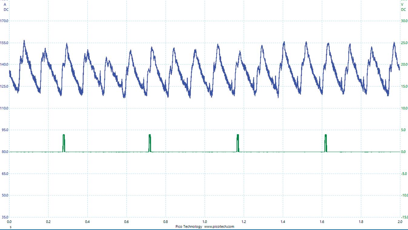
The pumps are fed pressure from the in-tank pump and should hold around 60 psi and rise to 90 psi when cranking (Figure 6). Once the engine starts to turn, the pumps will develop high pressures. I left the drain plug out of the oil pan and turned the key on. Nothing dripped out. I tapped the starter button and then quickly shut it off, and fuel started running out of the drain plug. One or both pumps were leaking into the crankcase.
For those of you keeping a tally of the diagnoses:
• Damaged wiring in the main harness
• Damaged drivers in the ECM
• Three faulty injectors
• Three more sets of injector seals
• Two high-pressure fuel pumps
Another phone call to the shop and an approval from the customer meant the pumps were on the way. I took all the undercoverings, starters, and fuel lines out. I then popped out the pumps to find one that looked OK, but the other one came out without the spring and piston (Figure 7). There’s the fuel issue. I fished out all the broken parts and installed the new pumps.
Once filled with fresh oil and a filter, I was able to start the vehicle. It started right up and ran relatively well. There was a ton of white smoke coming out of the exhaust due to all the old fuel burning off. After all the smoke cleared (pun intended), I checked the codes again.
SYSTEM PRESSURE 4.5 BAR - 65.3 IBF/IN2
STARTING PRESSURE 6.3 BAR - 91.4 IBF/IN2

There were codes for misfires on cylinders 4, 5, and 6, and cam correlation codes (the same ones it came in with) (Figure 8). All signs pointed to the timing being off on one bank. I let the shop owner know where we were at, and he asked me to prove the timing was off. I usually like to do this the easy way: cam/crank correlation, but I decided to get fancy and used the PicoScope WPS500x in-cylinder pressure transducer. My plan was to take a capture of each bank and overlay them. An in-cylinder pressure waveform, in my opinion, can be the best way to visualize individual valve events without taking anything apart. I am not a guru at this. I leave the high-end deciphering work to my friend Brandon Steckler. However, I was always good at playing “one of these things is not like the other.” We hooked the in-cylinder transducer up, saved the captures, and put them in an overlay program (Figure 9). You can clearly see that there is a difference from side to side.
What is off and by how much? I’m going to let you in on a secret; it doesn’t matter in this case. Does knowing that the intake cam is off 33.67893245 degrees change the fact that this brand-new chain will have to be reset? Nope. My diagnostic urge has been fulfilled, and I am now able to report the final findings to the customer.
Could the hydro-locked engine have caused the chain to jump? Maybe. The bank causing the code was on the same side as the completely full cylinder. This vehicle had the engine so diluted with fuel that it may have caused the tensioners not to hold pressure and allow the chain to jump. Could the chain not have been set up correctly at all? Again, maybe. There is no way to prove that. When I was at the rebuilder’s shop originally, I asked if they used the proper tools to assemble the chain, and they responded that they did. I have no reason to doubt them. I can only speak to where the diagnosis led me.

I reported my findings to the shop owner, and he relayed them to the vehicle owner. The vehicle owner was done with the vehicle at this point — he was
probably mad at himself for not taking it to his friend from the beginning. He asked that we put the vehicle back together and he was going to call it a loss and trade the
vehicle in for something less troublesome and complicated. We reassembled the vehicle and drove it back to the repair shop, and aside from the flashing check engine light, it didn’t drive half bad.
Is there a moral to this story? I don’t know. I can tell you that I trust my diagnostic process. When I had to make a call — no matter how bizarre and unbelievable it was — I felt confident.
I can relay that to you, build your process — trust your process. Don’t deviate even though something may seem unbelievable. These vehicles are only machines and follow simple rules when broken down to their base systems. Don’t discount the human factor; humans are fallible and can really mess things up whether we want to or not. And sometimes, after all this, you will have a good story to tell for years to come.


A conclusive test result is like a home run, but multiple test results that tell the same story? That’s more like a grand slam.
By Brandon Steckler
I’ll be the first to tell you that being a technician under pressure to get the job done quickly is not a stress-free position. This intensity is multiplied tenfold when you factor in the flat-rate pay scale for a technician (a concept I disagree with wholeheartedly).
With that, many will jump at the opportunity to draw a diagnosis from a single piece of data that correlates with an exhibited symptom. However, I urge you to step back and revisit the vehicle from a different angle.
As I’ve mentioned many times before, I always choose to take the diagnostic path that yields me the most information for the least amount of time or energy invested. I joke about this as my being inherently lazy. But the truth is it’s just more logical and efficient to conduct testing in this manner.
This is best discussed by way of example. Assume a vehicle was towed into the shop with a dead battery. Some may choose to conduct a capacitance test with the devices we typically implement at a multi-point service check (Figure 1). A failure would be a reason for most technicians to replace the battery. I agree with that approach, but we can’t stop there. There are still a few unanswered questions that must be pursued. The goal? To not fix the symptom but to fix the root cause of that symptom. In plain English, what caused the dead battery? Below are just a few questions that come to mind:
• Is the battery just old and expired?
• Is there a parasitic drain present?

• Is the alternator charging properly?
• If not, why? Is there a voltage drop elsewhere in the battery charging circuit?
Eliminating those above possibilities in logical order would mean beginning with the easiest test and concluding with the most difficult or most time-consuming test. That is, of course, if the customer approves the diagnostic time.
Although this is just a quick example of what I’m trying to portray, let’s follow through with an actual case study. You’ll see, had the tech not pursued the root cause of the issue, a lot of money and heartache would’ve been invested.
A vehicle was brought into the workshop with the complaint of “MIL illuminated.” Upon retrieving the vehicle
and preliminary evaluation with the scan tool, the technician discovered a DTC, P0304-cylinder No. 4 misfire was set in history (Figure 2)
A road test of the vehicle was conducted, and the engine was run throughout the entire operating range. The technician did note some slight misfire/ driveability concerns exhibited mostly during idle conditions. Considering she is still in the driver’s seat, the tech thought it best to monitor the fuel trim activity as it is a clear reflection of combustion quality or lack thereof, as well as an indicator of what type of misfire may be exhibited (like an ignition fault, an injection fault, or an engine mechanical fault) (Figure 3).
The misfire was felt at the time the fuel trim was monitored and the lack of compensation allowed the technician to determine the fault was unlikely to be
from the ignition system or the fueling system. This put an engine mechanical concern at the top of the list of suspected root-cause faults. Again, all from the driver’s seat.
The PCM’s misfire data was then monitored to determine if cylinder No. 4 may be the cylinder responsible for the driveability fault (Figure 4). The data PIDs concur that cylinder No. 4 is registering misfires. Although misfire detection software is much more reliable than in years past, it is not foolproof. Misfire data is just another piece of the diagnostic puzzle.
A relative compression test was conducted, and the results did not reflect a significant loss of compression (Figure 5). Although this seems contradictory to an engine mechanical fault diagnosis, we must keep in mind that a loss in compression isn’t always the result of an engine mechanical fault. The relative compression test is limited to only indicating if and how well the cylinder can harness and squeeze its contents.
As the technician eventually made her way beneath the hood to continue her diagnostic path, she noted an alarming, rhythmic noise resonating from within the engine compartment. This raised a few questions:
• Could the noise be from cylinder No. 4?
• Could the noise be related to the misfire?
• Could the noise be a different problem altogether?
• How can we determine where the noise originates from?
The above questions are indeed very logical, and I urge you as diagnosticians to consistently question yourself as you proceed through an analysis. The questions you ask should determine the tests you follow up with. The test results should answer the questions.


Implementing the mechanic’s stethoscope will allow her to pinpoint the noise with relative ease and help her decide how to proceed (Figure 6) Again, the takeaway is the test being performed is a bit more involved than just sitting in the driver’s seat with the scan tool, but it was justified as time well spent and it will definitely bring her closer to a conclusive diagnosis.
The engine noise was analyzed with the stethoscope from beneath the hood and the noise was loudest at the
cylinder head area of cylinder No. 4. This answers one of the above questions. However, it doesn’t necessarily indicate if the noise is from the valve train or the piston and rod assembly of cylinder No. 4.
The tech then chose to implement a pulse sensor and oscilloscope. The same stethoscope was used to locate the noise, however, instead of pumping information into the tech’s ear, the stethoscope was connected to the pulse sensor. The intensity of the generated pulse signal
will correlate with the noise occurrence and location. The pulse was not only visible but indicated the noise occurred twice per engine cycle (Figure 6). This puts a valve train noise at the bottom of the list of root causes since the camshaft turns once per engine cycle.
The vehicle was hoisted to allow access to the bottom-end area and noise was obvious in this area of cylinder No. 4 as well and equally as intense. The results of this test corroborate the noise is not likely to be in the valve train but internal to the engine block.
Considering the questions above, if we could temporarily eliminate the cause of the misfire, we could find an answer to all of them simultaneously. Considering this vehicle’s configuration, access to the COP ignition coils is easily obtained.
As the engine idled and the noise was exhibited, the COP of the suspect cylinder No. 4 was disabled. By unplugging the coil, a consistent misfire would definitely occur, but the bigger takeaway is since no combustion is taking place, the noise also vanished. What’s the point? The noise is not likely to be between the crankshaft journal and the main bearing cap, meaning that the noise is likely between the No. 4 piston and wrist pin or the connecting rod bearing and crankshaft journal. The cost of repair will vary depending on which fault is present. All the questions above can be answered if we take the analysis just a little bit further. With that, another set of questions comes to mind:
• Can the engine-mechanical fault be determined without disassembly?
• What test result may help draw that conclusion?
Some logical thinking is required to answer these questions, but there is a test that may help put the final nail in the coffin and deliver a diagnosis we

can be confident in speaking about with the customer. Because low-end engine noise is present, we do have to consider the collateral damage that may be taking place. Again, the idea is to give the customer the most accurate diagnosis possible so they can make a sound decision about whether the repair of this fault is right for them financially. Keeping the trend of analysis without disassembly is the theme of this article. By placing that same pulse sensor on the
dipstick tube, the tech obtained data that accurately depicts the conditions within the crankcase of the engine. She cranked the engine over several cycles and a pattern was noticed. The pattern indicated an increase in crankcase pressure once per engine cycle.
With some research of the firing order and adding an ignition sync on a second channel of the scope, the tech was able to correlate the rise in crankcase pressure with the top-dead-center (TDC)


BEYOND AFTERMARKET
EXPANDABLE SERVICE OPPORTUNITIES
CLOUD-BASED REPORT MANAGEMENT


6 — Using a pulse sensor in combination with a stethoscope and coupling it to an oscilloscope can offer a visual representation of the “noise” we hear. This can be correlated with different data (like an in-cylinder compression waveform) to help determine the source of the noise, its frequency, and specific events occurring. This capture from an unrelated vehicle demonstrates a worn and noisy exhaust valve rocker/cam

of cylinder No. 4, our suspect cylinder (Figure 7). This is an indicator that the surface between the piston assembly and the cylinder walls has been compromised. This one piece of data prevented the attempt at repair that could have been a lot of money and time invested without even addressing the collateral damage created by the engine noise we would be attempting to rectify. This would certainly be a bad day for the technician,
the shop, and the customer.
This final piece of data allows her to approach her service advisor and alert the customer of the bad news — or is it really good news? Regardless of whether the engine-mechanical fault is contributing to the misfire, the cost of repair makes engine replacement the only logical option. This customer must decide whether to get rid of the vehicle or invest in the replacement of the engine.
The takeaway from this case study is that all of this was obtained from data that is easily accessible, takes minutes to obtain, and requires no disassembly whatsoever. The technician got paid handsomely for honest testing that gave the customer a pinpoint engine-internal fault diagnosis without the associated cost of traditional disassembly/inspection. Although that would be the next step, the customer is aware and will be able to anticipate what is to be found upon disassembly and inspection, and that is worth something.
The next time you face making a tough call about something as expensive as an internal engine mechanical failure, don’t panic, and don’t guess. Implement multiple tests in a logical succession and you will find yourself placing multiple arrows in the same target. This will increase your level of accuracy many times over, decrease your applied diagnostic time by minimizing disassembly, and establish confidence in you that makes your job as a diagnostician very rewarding. That’s something we should all be proud of.


How to train your driveability mind for the electric vehicle world.
By Craig Van Batenburg
Iwas teaching a class in Montreal, Canada, and the department head wanted a class on pure electric cars. This was sometime in 2013. I went to work writing an outline for the class. In no particular order, I listed all the components used in an EV that were similar to a hybrid vehicle.
One by one, I added the EV side that related to the hybrid’s DC-DC converter, inverter, drive motor or motors, high voltage cables, detection systems for high voltage leaks, electric air conditioning compressors, Li-ion cells, modules, cooling systems, and more. I had never been asked for a class that excluded the internal combustion engine (ICE).
In 2013 hybrids were the dominant technology. I started my high voltage training company, ACDC, in the year 2000. A lone Honda Insight was the subject matter. As I made sense of this transition, I said in the classroom, “ACDC will make sure your 12V brain is well developed. Then we will create a high-voltage brain to use along with it. Where the two brains match up, the learning is easy, but sometimes ACDC will break the connection between the two, so your 12V brain is not used on a high voltage system.”
We still use that thinking today. It is 2024 and the ICE is no longer needed if a person, school, city, or company wants to change fuel sources. In 2013, that possibility was very limited. Change was happening then but ever so slowly, from all ICE to hybrids and now pure electric vehicles. In a technician’s lifetime, that change is fast. As a result, we must change our diagnostic approach.

As the class in Montreal was getting closer, I removed all references in my handouts to hybrids and added in all things EV.
Let us take a “no start” in a typical ICE-powered modern car or truck. In this case, the car gets towed in and the customer is not with the vehicle. This may be a new customer that does little preventive maintenance. You have no service records, and the service advisor sold one hour of diagnostics. You are already in a tough position. The work order has only “No Start” written on it. This is the way the shop operates. It is not technician-centered.
What do you do? You grab four tools. In your bag, you add a scan tool and a 12V jump box, an OBD-II breakout box, and a DVOM. You get in and
plug your break-out box into the DLC with the meter connected to pins 16 and 4. Before you try to crank the car over (KOEO), you check the voltage of the 12V battery. It reads 10.7V. No need to add more codes, so you locate the 12V battery. If you are lucky, once you open the hood, it is in plain sight. Attach the jumper box, get back in, and gather any codes. Make a PDF of the codes. Now you try to crank over the engine. It cranks over and will not start.
Basics again. Fuel? Gauge says just over a quarter of a tank. Clear the codes and try to start again. No start. Read the codes it has generated. Shut it down, back in the shop looking up service information. The clock has been ticking and you have 25 minutes left. Ten minutes on the computer. Back outside for a general look at the entire car. Needs tires, the oil is dark, the wipers


Once you know the car was recently purchased as a no-start and sat for two years makes the job very different than a “no start” that happened yesterday.
Now let us replace that same scenario from before with an eight-yearold Nissan Leaf EV. Out the door you go with a scan tool, a 12V jump box, an OBD-II break-out box, and a DVOM. Using your break-out box you read 10.7V at the 12V. You locate the 12V battery under the hood, connect the jumper box, and get back in. Scan the EV for any codes in “Power-On” mode, the EV equivalent of KOEO. Make a PDF of the codes. Now you try to go into “READY.” No READY light. The range says just over 30 miles left. Clear the codes and try to start again. No READY. Read the codes it has generated. Shut it down, back in the shop looking up service information. The clock has been ticking and you have 25 minutes left. Ten minutes on the computer. Back outside for a general look at the entire car. Needs tires, the oil is dark, looks like you are in the same boat.
are torn, the usual stuff. Back inside with the service advisor. Time is up. No need to push it into the service bay. You get another job to work on. Does this sound familiar?
In another shop, the diagnostic work can start with the customer coming over
before the work begins with their service records for a discussion about their car history and a quick look at the car while they are there. The one hour now can be used to sell the actual time and parts needed. There needs to be a fee before the tech gets deeply involved.
The technician and the service writer must get together and form an alliance on how to handle these situations. An old-fashioned system and new electric vehicles require a new approach. Once you are off to a better start, the triad (customer, shop, and technician) must all feel that their concerns are understood. The success of the repair requires that all three parties have their goals met. The shop needs to make a profit. The customer will return the next time service is needed. The technician knows it will not come back for the previous concern as the root cause was fixed. How do we get there?
The technician ultimately does the work. The car owner is a partner in all this, and they need to know that and should be encouraged to participate. That starts

with a great website that explains what the shop needs from them. Set up a time to sit down with each new customer and get the information you need. It can still be in written form, but an electronic device will be faster for keeping records. Complete a history of their vehicle’s service, repairs, recalls, accidents, and the personal information they are willing to share. Make sure the tech has access to that data. Establish a realistic fee after a 15- to 30-minute interview and a cursory look at the car. The tech can do a visual and scan check while the service advisor interviews the owner. “Who is the decision maker?” is a fair question to ask. Once the customer agrees to the fees and your process, he or she signs the work order, and the real work begins. Up to this point, you have every reason to charge a fee for what I call “intake and inspection” to get the customer to join the triad or find another shop.
Let us go back to the Leaf. It was towed in. The customer’s spouse drops the kids with a relative and picks up his wife. They were told to bring what
they have for service records and that they will need to remove their personal belongings from the car. They are at your shop now cleaning out their car. How much better would this help the technician? These electric vehicles will not be easy to repair. Even with some great training, the list of what can keep an EV from going into “READY” is not the same as an ICE. No more getting the 12V starter motor to crank the ICE. No more spraying “starter fluid” in the intake. The list goes on. Where do you start? A history of the EV is worth the time. That “intake and inspection” fee is designed for that purpose.
In the intake process you need to know:
• Condition of overall health of the EV
• Salvage title?
• Bought at auction?
• How many owners?
• How long have they owed it?
• Are all the recalls done?
• Too much rust?
• Unsafe to drive (bald tires)?
• Most of the service records are brought in
• Was it worked on by someone else for the same problem?
• How cooperative is the owner?
• Are you equipped and trained for this job?
• Do you need to learn and this job will help?
Once the above questions have been answered, and the owner is willing to pay you to find out more, the technician is now ready to spend the time needed to look at this Nissan Leaf.
If you are a technician who stays away from modern cars and trucks, this switch from ICE to EV will be very difficult. Most likely, you can stay busy for a long time, taking care of what you know. No problem with that.
On the other hand, a well-trained tech who loves to learn and finds new systems exciting will love the future. Retraining your 12V brain is possible — no matter what your age.


The Icon T8 Intelligent Diagnostic Scanner from Harbor Freight has a 2.0 GHz quad-core processor for lag-free operation and wireless vehicle communication capability. The scanner is compatible with 1996 and newer domestic, Asian, European, and exotic vehicles. Additional features include an 8” touchscreen, wireless OBD-II scanning, a holder for a stylus, and a flip-out stand located on the back of the scanner. It also comes with a heavy duty storage case with hinge pins that can be removed to convert the case into a tool tray.


APOLLO+ from Snap-on is a diagnostic assistant, ready with guidance and industryleading capabilities for every repair — from the routine to the mysterious. Technicians can’t afford to be slowed down looking for the best place to start. APOLLO+ is by their side for every vehicle they see in their bay, ensuring they have everything they need to get through the job. Fast-Track troubleshooting saves time with every code by providing the user with filtered information specific to the vehicle they’re working on. All this from the only US-based company designing, engineering, and supporting professional diagnostic products from the ground up.

The EZDS Zenith and G-Scan Software Updates are the second major update for the company in 2024 and are comprised of two updates. The first update enables Central Gateway access for Nissan vehicles among other enhancements to the software. The second update enables users to access the Secure Gateway Access control modules for multiple 2023-2025 Hyundai, Kia, and Genesis vehicles for Zenith users with Z5, Z7, or G-Scan tools.


Hunter Engineering’s Ultimate ADAS system is designed to eliminate errorprone manual layouts common to static ADAS calibrations. Ultimate ADAS combines Hunter’s standard-setting alignment technology with a guided target placement system for around-the-vehicle coverage. Gimbal-mounted lasers are the key component, replacing the inexact guesswork for strings, plumb bobs, and tape measures to cut setup time by 70 percent for certain procedures. The gimbals’ onscreen guidance provided by Hunter’s WinAlign software increases target placement precision by automatically compensating for non-level floors, monitoring for placement errors, and confirming accuracy with laser measurements each step of the way. Ultimate ADAS is currently exclusively available to Honda and Acura dealers, with availability set to expand.


The GEARWRENCH GWSMARTBT is a bidirectional diagnostic tool that operates through an app on the user’s smartphone. It features full bidirectional control and can perform live actuation tests, 23 vehicle reset and relearn functions, throttle matching, ABS bleeding, TPMS reset, and more. It also offers live data mapping, freeze frame capturing, and coverage for more than 150 car manufacturers. It includes free lifetime software updates as well as a complete twoyear warranty.


The Bosch ADS 625X features a 10” highresolution display, charging stations, and more. The ADS 625X tool includes advanced OE-level vehicle coverage that supports scanning, live data access, and complete bidirectional functions. Wireless VCI gives technicians the freedom to move through the bay and stay connected to the vehicle. The 625X performs full system scans with Quick-Scan and performs all-system DTC scans under 60 seconds. Additionally, the 625X has coverage for domestic, Asian, and European vehicles as far back as 1976.


The Vividia BD-5030i Borescope from Oasis Scientific is a semi-rigid USB borescope with a 0.19” diameter probe head and an 11’ long tube. It is equipped with both a front and side camera on the head and is designed to integrate seamlessly with the “USEE” Camera app (available on iPhone, iPad, and Android). Users can switch between both cameras and adjust their LED brightnesses within the app. Pictures and videos can be saved to connected devices.
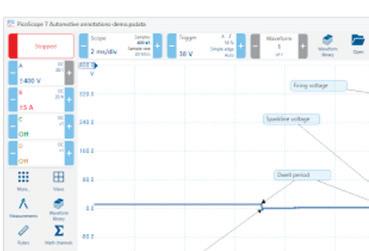


The PicoScope 7.1.39 Automotive Software Update from Pico Technology introduces an array of new features to the PicoScope platform. The update includes the ability to add annotations to explain or highlight specific events on the graph, both advanced and basic sets of keyboard shortcuts, a 10BASE-T1S Guided Test, and a 10BASE-T1S decoder for visualizing communication packets in numerical and voltage forms. The 7.1.39 update also introduces enhanced power measurements and math channels, command-line batch file conversion, bulk downloads with the Waveform Manager, improved language support, free-text search in the Waveform Library, enhanced import filtering, and updates to guided tests.


The industry’s first AI solution for collision repair planning, asTech Insights analyzes the results of a pre-scan and then automatically generates custom collision repair recommendations to help users build a comprehensive repair plan in minutes. Users can maximize the value of every repair and ensure every vehicle returned to their customers is fully restored to pre-accident conditions.


The RLink J2534 from TOPDON is engineered to be a pocket-sized all-in-one diagnostic solution. It is compatible with OE software across more than 13 brands, delivering OEM-level diagnostics, programming, and coding at an accessible cost. With support for CAN FD and DoIP protocols and compliance with J2534 and D-PDU standards, it covers a wide array of modern vehicles. The RLink features a Driver Management System that allows users to access TOPDON technologies.


The Smoke Pro Air from Redline Detection comes with its own onboard micro air compressor, eliminating the need to connect to air lines or inert gas. By eliminating the need for shop air or inert gas tanks, technicians can quickly diagnose, locate, and repair leaks anywhere, anytime. Smoke Pro Air improves the accuracy of repairs and eliminates comebacks by verifying that difficult-to-find component leaks are repaired accurately the first time, the company says.


The E-XTEQ DCBS Mobile, No. EZ-0268-A, is a diagnostic and charge battery station that features built-in diagnostic functions to service and troubleshoot battery conditions, including state of charge/state of health. It can perform IR, CCA tests, true reserve capacity, and automatic load test and charge acceptance functions, as well as functioning as a Constant Current Constant Voltage power supply. It also offers a clean, consistent power supply for vehicle ECU reflashing.


The MOTO Mini from CanDo takes the global coverage of the MOTO Pro and breaks it down to market-specific coverage, making it ideal for shops working with American, European, or Asian motorcycles and powersports vehicles. Packaged in a 7” Android tablet, OE-level software, including full bidirectional controls, calibrations, and special functions are included, as are all necessary cables and one year of free software updates.


Exair’s Ultrasonic Leak Detector (ULD) is a handheld instrument designed to help locate the source of leaks in a compressed air system. With this tool, testing the various unions, pipes, valves, and fittings of a complete installation can be done at distances up to 20’ away. The ULD can detect the vibrations of high pressure gases, creating an audible sound through supplied headphones as well as indicating intensity via front-facing LED display as it moves closer to the leak origin. Adjustments can be made to filter out background noise with “+” or “-” buttons for fine-tuning sensitivity. The updated ULD offers an increased ability to detect leaks in hard-to-reach areas while complying with the IEX 61326-1 standard.
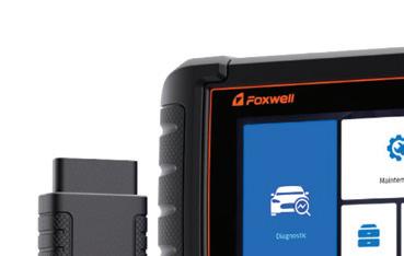


The i70BT Automotive Diagnostic System from Foxwell is a diagnostic scanner with Wireless VCI Foxlink I. It inherits the same Foxwell advantages in car fault diagnostic tech, such as multiple manufacturer coverage, service functions, and accurate test data, making it ideal for busy garages or workshops. The i70BT supports all system diagnoses as well as oil reset, EPB, SAS, and 35 service functions. Users can run bidirectional tests and perform automatic VIN readings. Additionally, the i70BT supports CAN FD/DoIP, has a wireless connection, and features one-touch update.


The Autel MaxiSYS IA700 ADAS Calibration Frame System features a modular, compact design that can be quickly disassembled for transport or storage. It uses a robotic crossbar with six high-definition tracking cameras and includes advanced features such as wheel alignment pre-checks, optical positioning, and unlevel floor compensation. The IA700 also includes the Guided ADAS application, which allows users to calibrate recently released vehicles that aren’t yet covered by Autel software.


The ANSED Diagnostic Solutions HD Digital Video Scope Kit w/ 3.9mm Articulation Camera Probe, No. DVSK39ART, lets the user look back up to a full 180 degrees. The monitor is an easy handheld unit weighing less than 9 oz., has a 3.5” diagonal display, a hi-def resolution of 1280 x 720, and takes photos and videos. The Articulation Probe is 1m (approx 36”) long and rated IP67 for dust and fluid. The DVSK-39ART Kit includes an 8G SD mini card and a USB cable for charging, all in a hard plastic carrying case.


The Axone Nemo Plus from TEXA USA is equipped with the Windows 11 operating system. The tablet features an Intel N100 processor, 16 GB RAM, and 250 GB SSD storage. It can connect to Wi-Fi and Bluetooth 5.3 modules for connection to the TEXA vehicle interfaces. A built-in camera allows the user to capture details during maintenance operations and create reports that can be given to customers or sent to technical assistance.


The Duralast Wi-Fi Borescope, No. 89-001, features a high-resolution, multiple-aspect camera (1920 x 1080, 1280 x 720, and 640 x 480) with adjustable LED lighting. It has an independent Wi-Fi signal that can connect to a phone or other device. Users can take high-resolution videos or pictures in areas like cylinder heads, gas tanks, and diesel injectors. The lens and cable are IP67 certified, dustproof, and waterproof in up to 3’ of water for up to 30 minutes. Its 58” cable is flexible yet rigid enough to give users access into hard-to-view areas. The compact camera is only 6mm in diameter, allowing user access to small areas. It has a mobile app for both Android (2.3 and up) and IOS (6.0 and up) devices.

The Matco Tools Maximus 5.0 diagnostic scan tool is ideal for master technicians. Engineered with advanced technology, the Maximus 5.0 is designed to deliver a combination of automotive intelligence, quick navigation, and ergonomic handling for optimal efficiency. Offering a new intuitive user interface, a larger touchscreen, increased memory, and extended battery life, the Maximus 5.0 comes fully equipped and is available with carline (No. MDMAX5CL) or carline and heavy duty software (No. MDMAX5CLHD).


The Battery Charger and Analyzer, No. 6021AGM, from Associated Equipment is designed to provide 6V, 12V, and 24V charging capabilities for vehicle batteries including AGM and EFB. The charger also has a manual mode with the ability to adjust the time up to 180 minutes, safety features, as well as safe start and auto restart in the AGM setting. Additionally, the charger performs an automated load test and automatic surface charge removal and will notify the user if the battery is out of the parameters for conducting the load test.


The DHC BTW350 is a wireless battery and electrical system tester that conducts tests via Bluetooth connection to the DHC app on a smartphone or tablet, which then displays real-time results. The app-based interface is not limited by cable length, and it allows users to edit and save customer and shop information as well as share test results with customers through text or images. It supports 6V and 12V batteries and includes 12V and 24V system tests. It comes with a 12-month warranty.

The Rotary Mobile ADAS Calibration System is designed to offer shops a quick and cost-efficient way to perform static and dynamic calibrations and resetting of ADAS correctly with fewer physical targets. The portable system features a 75” 4K HD monitor that creates digital non-scaled vehicle targets, 360-degree motion casters, accurate laser positioning of machine to vehicle via Bluetooth technology, step-by-step guided frame adjustments to reduce errors, and offers software versatility for users to choose an OEM or MCS Windows-based tablet. The system is also customizable with four different levels to choose from.


Designed and engineered with cutting-edge technology, the X-431 Throttle V from Launch Tech USA delivers a combination of automotive intelligence, quick navigation, and ergonomic handling for optimal efficiency. As the most powerful automotive scan tool in the X-431 family, the X-431 Throttle V provides fast performance for optimal efficiency during diagnostics and vehicle repair. With access to X-431 FIX and CODE ASSIST carline repair information, the diagnostic repair process can effectively and accurately be accelerated with confidence.