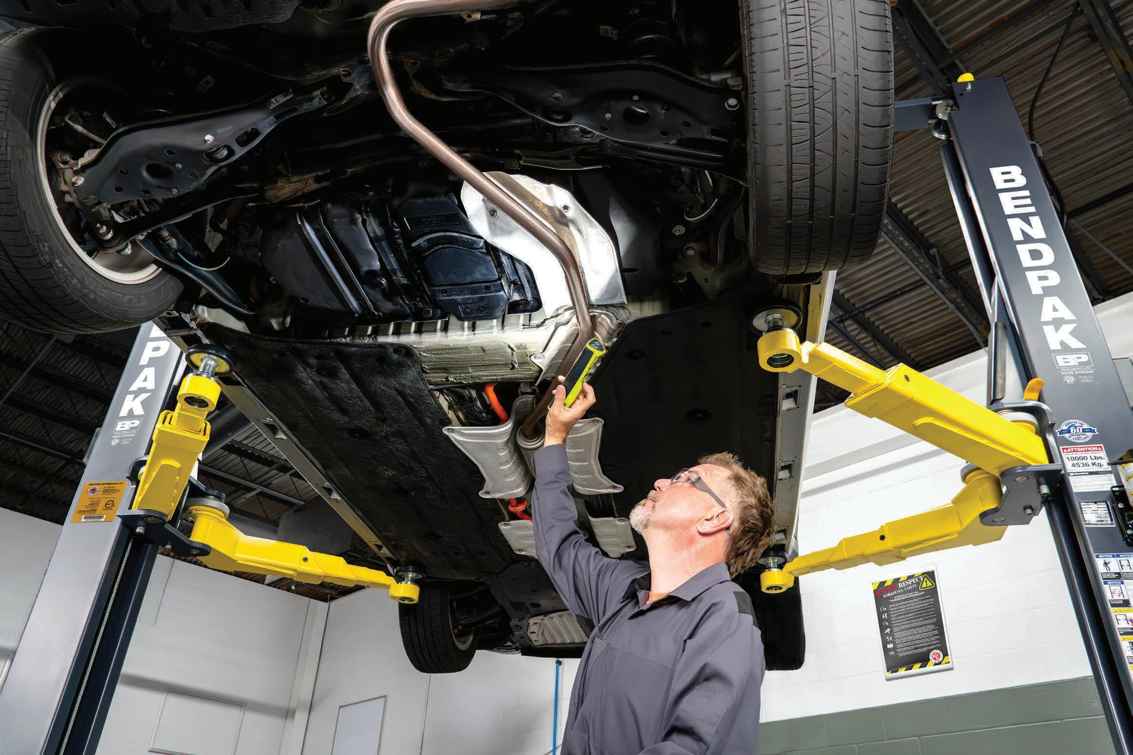
Our 10AP Series offers the convenience of wide or narrow installation wrapped up into one configurable package. This durable, safe, and reliable car lift features an expandable top beam and BI-METRIC™ arms to suit virtually every vehicle lifting requirement – symmetric or asymmetric. The 2-in-1 design gives operators the option of loading vehicles either symmetrically (centerline of vehicle at column) or asymmetrically (centerline of vehicle behind column). The simple, yet highly sophisticated design is sure to keep operating costs low and productivity high. Check out the full line of 10AP lift series at bendpak.com or call us at 1-800-253-2363
BendPak Model
STARTERS
TECHNICAL
10 Low Speed Pre-Ignition
Understanding LSPI and how oils protect against destructive combustion
Erik Screeden
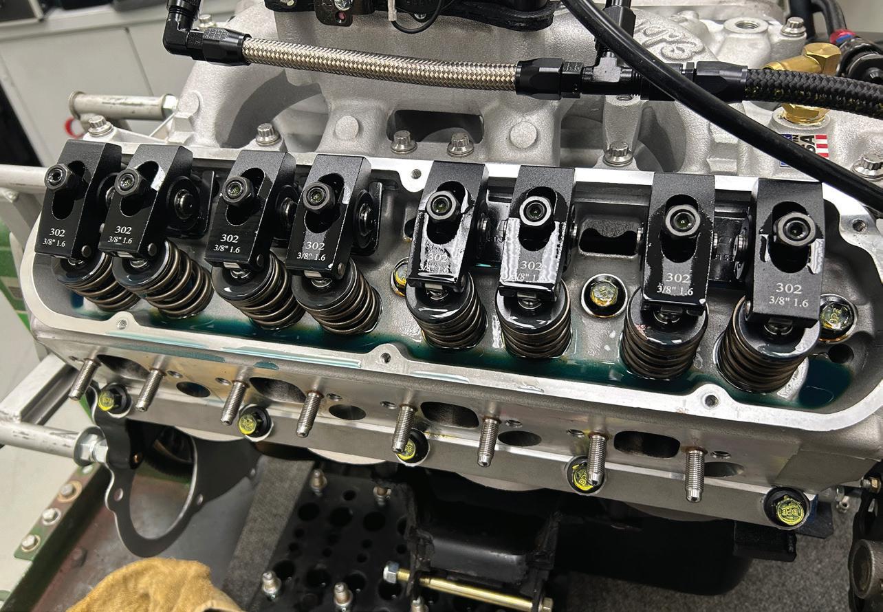
16 Engine Break-In
Tips for safely starting a fresh engine
Mike Mavrigian
22 Modern GDI: What Technicians Need to Know
Mastering injector design, spray patterns, and carbon buildup issues
Jeff Taylor
29 The Data Doesn’t Lie Solved: 2008 Jeep Wrangler
3.8L, P0340 + P0344
How three engine replacements led to the real diagnosis
Brandon Steckler
30 EV Essentials All Techs Need to Know
What basic EV repair knowledge techs need — and why now
Craig Van Batenburg
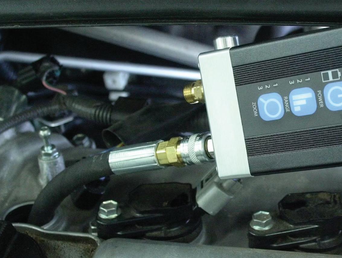
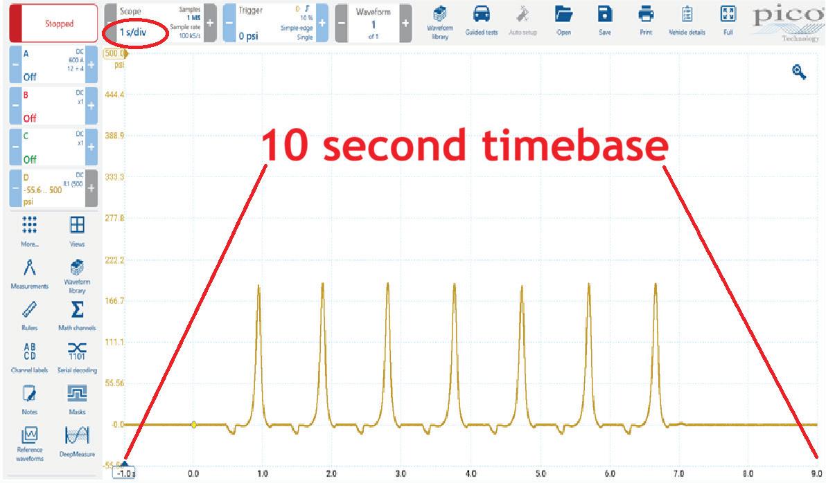
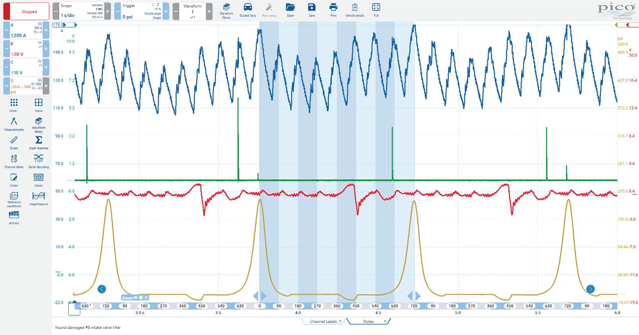
36 Pressure Waveform Analysis Know how to analyze the capture for accurate engine diagnostics
Brandon Steckler
TOOLBOX
Printed in the USA. Copyright 2025 Endeavor Business Media, LLC. All rights reserved. No part of this publication may be reproduced or transmitted in any form or by any means, electronic or mechanical, including photocopies, recordings, or any information storage or retrieval system without permission from the publisher. Endeavor Business Media, LLC does not assume and hereby disclaims any liability to any person or company for any loss or damage caused by errors or omissions in the material herein, regardless of whether such errors result from negligence, accident, or any other cause whatsoever. The views and opinions in the articles herein are not to be taken as official expressions of the publishers, unless so stated. The publishers do not warrant either expressly or by implication, the factual accuracy of the articles herein, nor do they so warrant any views or opinions by the authors of said articles.
Endeavor Business Media provides certain customer contact data (such as customers’ names, addresses, phone numbers, and e-mail addresses) to third parties who wish to promote relevant products, services, and other opportunities that may be of interest to you. If you do not want Endeavor Business Media to make your contact information available to third parties for marketing purposes, simply call toll-free 877382-9187 or email MotorAge@omeda.com and a customer service representative will assist you in removing your name from Endeavor Business Media’s lists. Motor Age does not verify any claims or other information appearing in any of the advertisements contained in the publication, and cannot take responsibility for any losses or other damages incurred by readers in reliance of such content. While every precaution is taken to ensure the accuracy of the ad index, its correctness cannot be guaranteed, and the publisher waives all responsibility for errors and omissions
ONLINE
WE’RE EXPANDING OUR NETWORK
We’ve rebranded our YouTube channel to unite all vehicle service and repair content under one authoritative platform. The new Vehicle Service & Repair Video Network consolidates expert training, diagnostics, and industry intelligence from Motor Age, PTEN, Ratchet+Wrench, and six other leading brands. Designed for today’s technicians navigating ADAS, EV technologies, and complex diagnostics, the channel delivers best-in-class technical content for service professionals.
VIDEO ADAS AWARENESS FOR TECHNICIANS
L e arn why ADAS calibration is now critical to everyday repair work. Routine procedures like replacing struts or installing headlights can misalign complex driver assistance systems — lane keep assist, adaptive cruise control, and automatic emergency braking. Many technicians overlook ADAS outside collision repair, but mechanical adjustments demand equal attention. Learn how radar calibration, camera positioning, and steering angle sensors interact, and discover Launch Tech USA’s scalable three-in-one approach for shops.
EDITORIAL
GROUP EDITORIAL DIRECTOR
Chris Jones / christopherj@endeavorb2b.com
EDITOR
Mike Mavrigian / mmavrigian@endeavorb2b.com
MANAGING EDITOR
Chris Jones / christopherj@endeavorb2b.com
TECHNICAL AND MULTIMEDIA CONTENT DIRECTOR
Erik Screeden / escreeden@endeavorb2b.com
TECHNICAL EDITOR
Brandon Steckler / bsteckler@endeavorb2b.com
ASSOCIATE EDITOR
Madison (Gehring) Hartline / mgehring@endeavorb2b.com
Subscription Customer Service 877-382-9187; 847-559-7598
MotorAge@omeda.com PO Box 3257 Northbrook, IL 60065-3257
REPRINT SERVICES reprints@endeavorb2b.com
MEMBER OF:
Organize your tool chest: Time is money
A TECHNICIAN’S TOOL ARSENAL is the lifeblood of his or her trade. An adaptation of an old military term can appropriately be applied: These are my tools. There are many others like them, but these are mine. Without them, I may be useless. Without me, my tools are useless. The combination of my tools and my training results in a force to be reckoned with.
A typical tool chest may contain hand tools, such as open-end and combination wrenches in both fractional and metric sizes; 6-point and 12-point sockets, both short and deepwell in fractional and metric sizes; male hex wrenches and male and female hex bits. It may contain an array of sizes of flat blade and Phillips screwdrivers; 1/4-drive, 3/8-drive, 1/2-drive, and 3/4drive ratchets; ratcheting micrometer and digital torque wrenches; torque/ angle torque wrenches; hammers, etc. Add to this a plethora of specialty tools that apply to the type of work the individual tech must be able to address, as well as power tools including pneumatic wrenches and impacts, cordless wrenches and impacts, hand-held pyrometers, soldering guns, crows-foot and offset wrenches, screw extractors, punches and drifts, chisels, etc. On the electronics and scan tool side of the arsenal, consider multimeters, jumpers,
multi-make, and make-specific scan tools. The list goes on and on (and on).
Having the appropriate tools, from the most simple to the most advanced, is obviously important. However, having immediate access to a specific tool in a timely manner is also important. Maintaining a clean and well-organized tool chest is key. If a tool chest is disorganized, the tech can waste valuable time when searching for a specific tool.
When you see a tool chest that is organized (all fractional sockets clean and in size-graduated order, all metric sockets organized similarly, etc.), that is a clear indication that the tech is an organized professional and ready for any task at hand. If a tool chest is a disaster (dirty, greasy tools, crammed into drawers in a jumbled heap with no clear organization), that’s an indication of a tech who may not be detail-oriented, wastes time, and perhaps cannot be relied upon to boost profits for the shop and has the potential for shoddy work.
A pro tech takes the time at the end of each workday to clean his or her tools and place them back into the tool chest in proper location and order, in preparation for the following day.
Keep tools clean and well-organized. Time is money.
MIKE MAVRIGIAN MOTOR AGE // EDITOR mmavrigian@endeavorb2b.com
Clean Those Threaded Holes
Sometimes, basic precautions are ignored, especially when you’re in a hurry. Whenever you’re about to install a bolt into a blind threaded hole, first make absolutely sure that the hole is clean and dry. If oil or water is trapped inside the threaded hole, the tip of the bolt will try to compress the liquid, resulting in a hydraulic lock condition. As we all know, you can compress air, but you can’t compress a liquid.
This is important when dealing with any blind hole, but is especially critical for blind cylinder head bolt holes or main cap bolt holes in the block, where high clamping loads are required. If a puddle of oil or water lies in the hole, the forces that result from torquing the bolt can be great enough to break the block in the thinnest wall section adjacent to the
hole (cracking the block or breaking through to a water jacket for instance). Before component installation, always clean the hole of any liquid, then run a chaser tap (not a cutting tap!) through all holes to clean the threads, and blow compressed air into the holes and verify that the holes are dry and clear of any debris. A chaser tap will clean and re-form the threads, while a cutting tap will remove metal and reduce thread integrity/strength.
Not paying attention to this can easily result in a very expensive fiasco. The force created by trying to compress a liquid will try to escape, and if there’s a way out, the compressive force will find it. Even if the block isn’t damaged, the liquid-contaminated hole will prevent even and insufficient clamping load, certain to result in a failed head gasket.
Vette Diff Cover
You may encounter a strange noise from the rear of a 2014-2019 Chevy Corvette equipped with a 6.2L engine and 8L90 automatic transmission, but without electronic posi-traction limited slip. The owner may complain about a “warbling” noise at the rear when operating in the 1,500 rpm range when travelling up a slight grade. The cause may be excessive clearance of the bushing in the left side differential cover. The fix involves replacing the left side rear axle housing cover with P/N 84705711.
Home Brew Fix For Snap Rings
Sometimes the smallest, simplest thing can make a difficult job tolerable. Especially in areas of the country, such as the Rust Belt, where we deal with rust and corrosion on a routine basis, you may have had difficulty removing he large snap rings that retain the front wheel bearings in many different car makes, especially Asian vehicles. A challenge that crops up is that there is no hole for the snap ring pliers. The style of snap rings may feature a type of hook that can corrode and rust off, making the job of removing the ring a real problem. One solution involves drilling your own holes! Simply drill two holes, insert the snap ring pliers, and tap lightly on the pliers.
TO CLEAN THREADED HOLES, never use a common cutting tap. Use only a chaser tap, which is designed to maintain thread form and strength. PHOTO BY MIKE MAVRIGIAN
RETAINING RING PLIERS 2-PC HEAVY DUTY WITH INTERCHANGEABLE TIPS
Benz High Voltage Warning
A high-voltage battery warning message may appear in the instrument cluster on 2016 and later Mercedes-Benz hybrid and EV vehicles equipped with an auxiliary supplemental heater. A possible no-start condition may be found, or the vehicle charging may be interrupted or inhibited.
Moisture or corrosion may be present in the high voltage PTC heater booster female connector (N33/5 female connector 1). Inspect the 12V female connector for damaged main silicone seal, missing blind plugs, damaged individual conductor seals, or foreign object contamination. Replace the high-voltage PTC heater booster. The wiring harness can be repaired if necessary.
DTC codes may appear as follows:
• P0A0BOO (interlock circuit of the high voltage on-board electrical system malfunction)
• B10BE00 (switchover valve on PTC heater booster high voltage has a malfunction)
• P0A0A00 (interlock circuit of the high voltage system has an electrical fault)
• P0A0D00 (interlock circuit has a short circuit to positive)
• B19A400 (LIN bus 2 of the A/C system has a malfunction)
P142600 (There is a vehicle-side isolation fault in the high voltage system).
Accommodates internal ring sizes from 3-1/16" to 6-1/4", external ring sizes from 3-1/2" to 6-1/2", and includes tip sizes of .120" in 0°, 45°, and 90° configurations.
Spring ratchet locking mechanism securely holds against snap ring tension
Thumb release allows for smooth and controlled tension release
Cushion grip for comfort
16-INCH OVERALL LENGTH OF PLIERS
Low Speed Pre-Ignition:
Causes and How Engine Oils Combat
It
LSPI is a destructive, abnormal combustion event that occurs most often under low engine speed and light load conditions
BY ERIK SCREEDEN
SUCK,
SQUEEZE, BANG, BLOW. This simple idiom is taught to automotive students as an introduction to the four cycles that make up a four-cycle internal combustion engine: intake, compression, combustion, and exhaust. These events happening in time are the cornerstone of locomotion in four-cycle gasoline engines. But when the timing of these events is compromised, a change in a manner, regardless of how small, can often yield catastrophic results.
Low-speed pre-ignition, or LSPI, is a destructive, abnormal combustion event
that occurs most often under low engine speed and light load conditions, like hard acceleration from a stop or “lugging” the engine up a hill in too high a gear. Unlike traditional pre-ignition or detonation, which can be managed with changes to octane or ignition timing. LSPI occurs suddenly, and the result can be severe: cracked pistons, broken rings, or bent connecting rods are not uncommon results of LSPI.
Over the past two decades, engine design and technology have evolved rapidly. Automakers have turned to smaller displacement, forced induction, and direct injection to help meet ever-tighter fuel economy and emissions standards. While these engines deliver impressive power and efficiency considering their displacement, it doesn’t come without its challenges. And just like how auto manufacturers had to turn to new technology to get efficiency and power, so too did they have to turn to new advances in lubrication technology, particularly changes in additive chemistry, to help curb this oncefeared phenomenon.
What is LSPI?
Pre-ignition and detonation are nothing new. Pre-ignition occurs when the air/ fuel mixture ignites before the spark plug fires, caused by a hot spot in the combustion chamber. Detonation is the uncontrolled combustion of the air/fuel mixture due to excessive heat and pressure. But LSPI is different. Where traditional detonation events happen at higher engine RPM and loads, often when ignition timing is too aggressive or fuel octane is insufficient, LSPI happens most often at low RPM and high load situations. Again, when the vehicle is accelerated hard from a stoplight, the engine is lugged up a steep grade or produces full boost at low speed. These situations create high cylinder pressures and temperatures, setting the stage for LSPI.
LSPI is dangerous because of its intensity and unpredictability. Events occur at random with high-pressure spikes,
at times double what the engine was designed for. While traditional knock can often be detected and managed by the engine management system, it’s the unpredictability of LSPI that can make it catastrophic. These unchecked pressure spikes can easily crack a piston, shatter a ring land, or bend a connecting rod.
As turbocharged gasoline direct-injected engines became more common in the early 2010s, auto manufacturers saw an uptick in unexplained engine damage during durability testing. The industry quickly realized that they were dealing with a new phenomenon that required a new line of defense.
The Science Behind the Phenomenon
Before we can talk about the important role engine oils have in preventing LSPI events, we need to take a look at why it happens in the first place. Multiple contributing factors lead to LSPI occurring. To borrow a common analogy from aviation accident investigation, think of all the contributing factors as individual pieces of Swiss cheese. Individually, these issues are often harmless, but stack them together with aligning holes, and you can find yourself with a clear path to failure.
Fuel Characteristics
GDI engines inject fuel directly into the combustion chamber, which has benefits such as precise fuel delivery, allowing for higher compression ratios due to GDI’s cooling effect, and leaner overall operation because of a stratified fuel charge operation. This allows for a greater opportunity for that fuel to mix with residual oil droplets on the cylinder walls and then enter the combustion process.
Engine Design
Forced induction allows more air into the combustion chamber, and when paired with downsized displacements, the brake mean effective pressure is significantly higher than their naturally aspirated counterparts.
VFXARTIST / SHUTTERSTOCK
Engine downsizing forces engines to operate closer to the maximum load more often, which increases stress during acceleration events.
Fueling directly into the combustion chamber, bypassing fuel encountering the intake valve, like you get when fuel is introduced at the port or via the throttle body, can lead to carbon deposit buildups that disrupt airflow entering the cylinder, affecting air/fuel ratio.
Operating Conditions
LSPI occurs most often at low rpm and high load, when drivers expect strong torque from their turbocharged engines.
There is still considerable debate on the cause of LSPI, but the general working theory is that oil and fuel interactions in the combustion chamber are the driving factor of this destructive phenomenon. During the intake and compression strokes, small amounts of oil can enter the combustion chamber by either bypassing the rings (blow-by) or via a residual film on the cylinder walls. Under high loads, this oil film can detach and form fine droplets. When mixed with fuel, these oil fuel droplets can auto-ignite before the spark plug fires. If normal ignition occurs around the same time, the overlapping flame fronts can result in pressure spikes that can significantly exceed design limits, causing forces that components in the rotating assembly were never intended to take.
Early Industry Response
When automakers first started experiencing LSPI, they were taken by surprise. The phenomenon was sudden and severe, and often the result was the need for complete short-block replacement. And because LSPI occurred so randomly and during normal driving, significant warranty and durability concerns were present.
Early responses from the OEMs were to limit torque output at lower rpms by using engine tuning strategies. Controlling boost pressure and ignition tim-
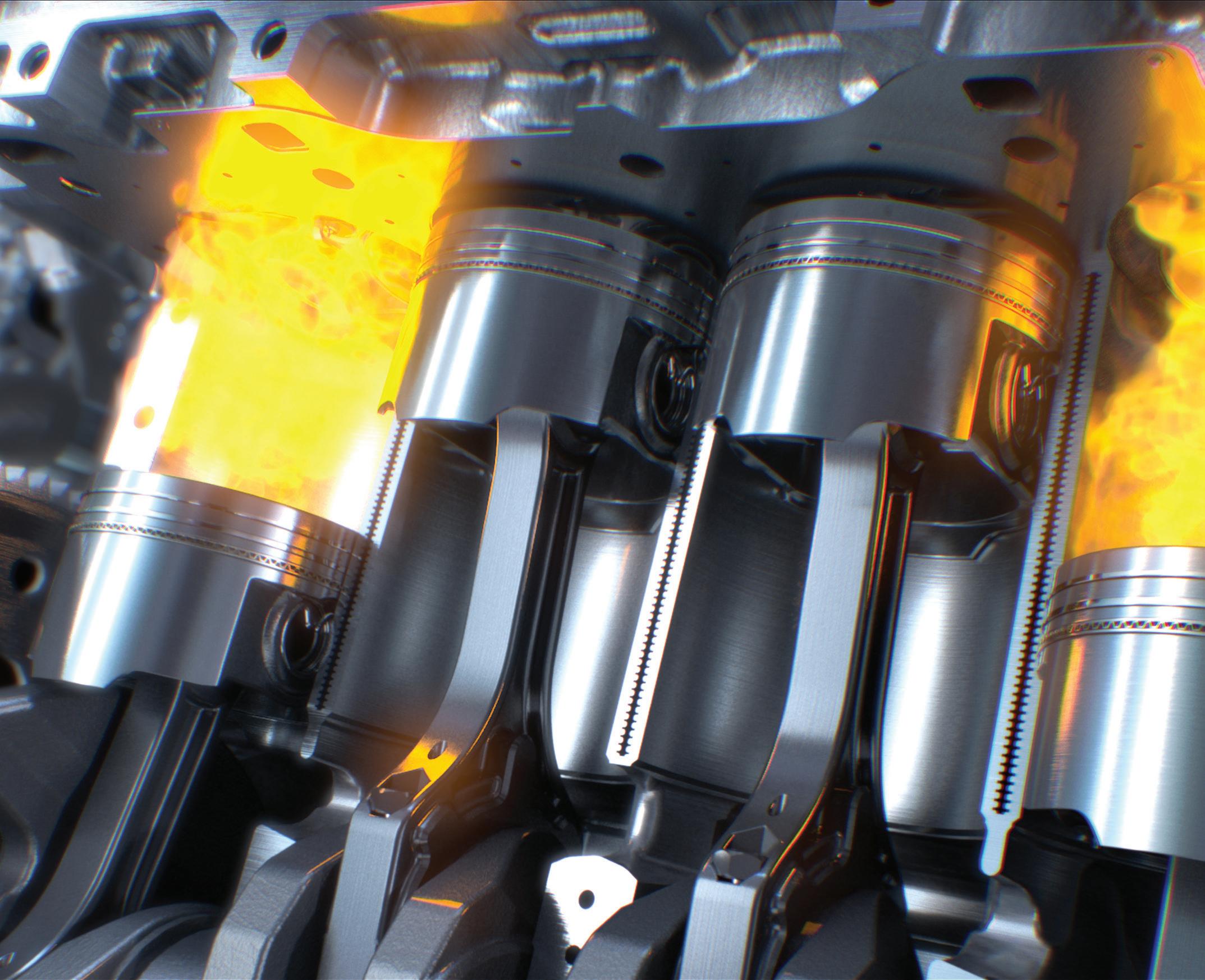
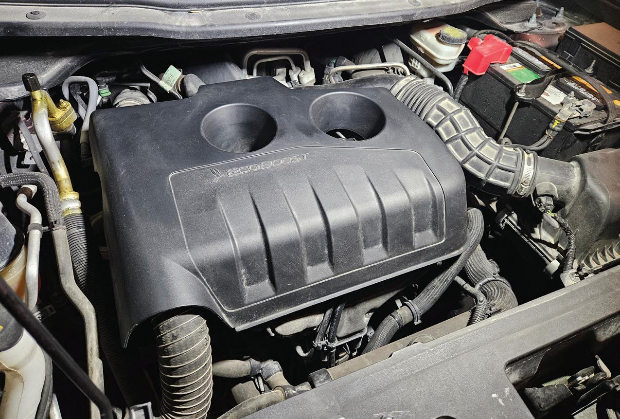
WITH THE trends of engine downsizing and use of forced induction to meet ever-tightening fuel mileage and emissions standards, engines like this 2.3L EcoBoost have become commonplace in mid-sized SUVs like this 2016 Ford Explorer.
PHOTO BY ERIK SCREEDEN
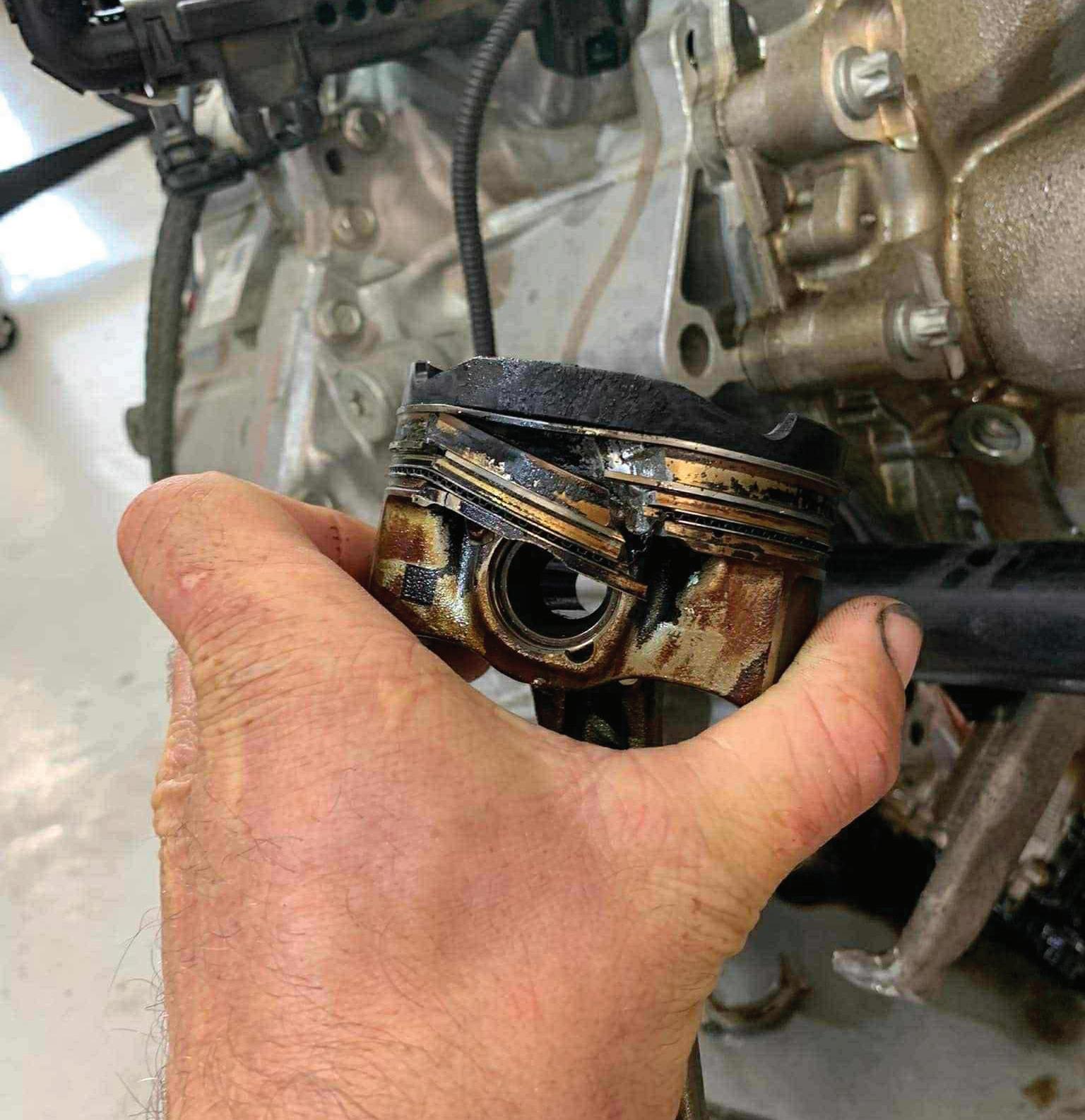
THIS IS a classic example of LSPI damage, where the piston breaks below the compression ring just above the wrist pin. This example is from a BMW B48, common across the BMW/Mini lineup. Its use of GDI and twin-scroll turbocharger makes it a popular engine platform.
PHOTO BY JUSTIN MORGAN
ing under high load/low speed operation. While there was initial success in reducing the frequency of LSPI, it also lessened driver experience by dulling the torquerich character that made forced induction vehicles fun in the first place.
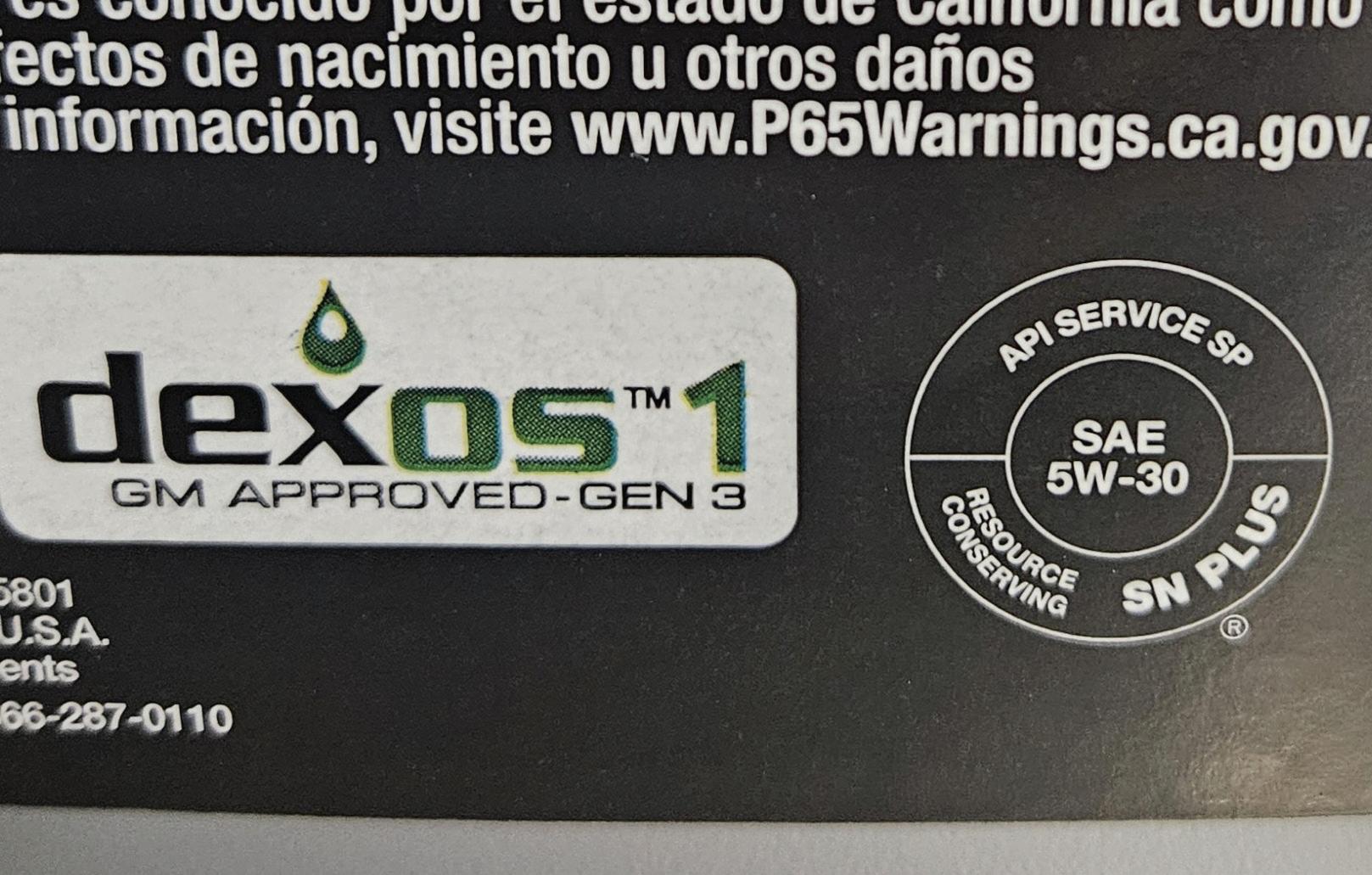
Automakers realized that there was a chemistry component to the LSPI phenomenon. Researchers found that the calcium-based detergents used to help neutralize acids and provide rust protection could increase LSPI frequency by providing fuel for oil auto-ignition. General Motors was one of the first to recognize this issue and quickly developed an LSPI test as part of their dexos1 Gen2 specification. This standard change forced oil companies to reformulate their offerings to meet the new requirements and proved to be a turning point in addressing root cause of LSPI.
Role of Engine Oils in LSPI Mitigation
It didn’t take long for the industry to realize that LSPI was not simply a hardware issue, and quickly the focus turned inward to the fluids circulating within the engine. Researchers discovered that oil chemistry had a significant impact on LSPI event frequency. Oil additive and detergent packages, used for wear and deposit control, could elevate or reduce the risk depending on what is used.
Calcium-based detergent packages had been the standard for decades for controlling deposits and neutralizing acids in engines. Calcium, while very effective for cleanliness, was also found to elevate LSPI events. When oil droplets enter the combustion chamber, the calcium compounds act as ignition promoters when mixed with fuel. This lowers the threshold for uncontrolled pre-ignition. This happens because when the calcium reacts with the fuel, it forms a new lower-octane compound. The lower-octane value of this new compound makes it prone to auto-ignition when subjected to the cylinder pressures seen in modern turbo GDI engines. No longer can detergents be thought of as simply sludge
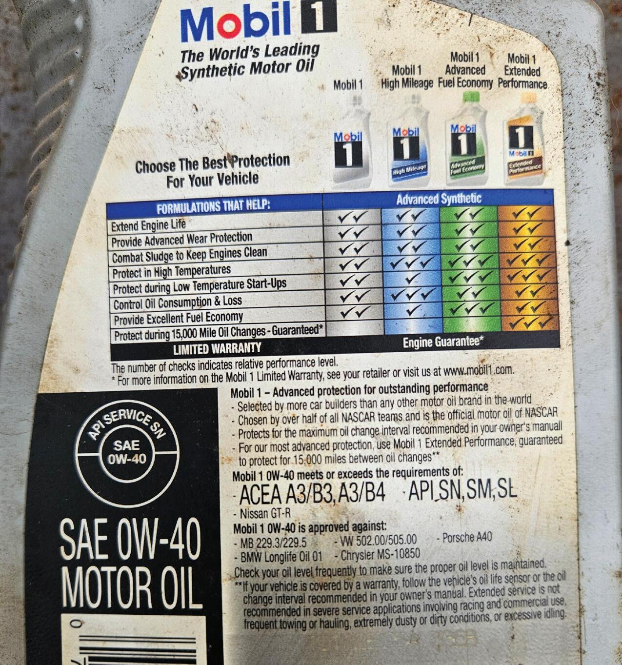
API SERVICE SP oil is the most recent American Petroleum Institute category. This service category was introduced in 2020 and was designed primarily to protect against low-speed pre-ignition events, as well as additional timing chain wear protection and high-temperature deposit protection.
PHOTO BY ERIK SCREEDEN
API SERVICE SN oil was introduced in 2010. Around the same time, T-GDI technology really started to gain traction with auto manufacturers. While it provided good protection against high-temperature deposits and good sludge control, it did not provide adequate LSPI protection.
PHOTO BY ERIK SCREEDEN
preventers; manufacturers have become acutely aware of their link to catastrophic engine failures.
Lubricant companies, to combat LSPI, had to shift gears and address their additive chemistry. By having a reduction in calcium-based detergents and replacing them with magnesium-based products, they were able to maintain similar acid neutralizations without the elevated danger of LSPI occurrences. Lubricant companies also looked at their base oil technology. The American Petroleum Institute’s base oil classification is divided into five main groups. By using more refined category III and IV base oils, oil manufacturers can create oils that have more resistance to evaporation, meaning less mist enters the combustion chamber. Reducing the chance of oil/fuel auto-ignition. Molybdenum friction modifier packages and zinc dialkyldithiophoshate (ZDDP) additives are also added to have a stabilizing influence on combustion. Though, especially with ZDDP, it should be kept within limits to protect catalytic converters.
Once research results behind LSPI occurrences started to become published, auto manufacturers reacted with new oil specifications and requirements. General Motors was the first in 2017 to require
LSPI testing by lubricant companies in order to carry the new dexos1 Gen 2 label, forcing suppliers to reformulate. API SN+ followed in 2018 as a stopgap standard by the American Petroleum Institute in response to LSPI concerns. Then, in 2020, LSPI testing became a permanent requirement for the new API SP/ILSAC GF-6 designation. This ensured that all oils would protect against LSPI to become licensed.
Implications for Technicians
For the technician, LSPI is an important reminder that failure to consult service information and follow recommended standards set forth by the vehicle manufacturer can have catastrophic results. For decades, oil weight and viscosity were the primary concerns when choosing the oil for a customer’s vehicle. Now, two bottles with the same viscosity rating may be formulated very differently. API SP oils have been tested to suppress LSPI events, while older formulations may not provide the same protection. For technicians and service writers, this is also an opportunity to educate customers. Many vehicle owners still prefer to handle maintenance tasks themselves, while deferring to professionals to handle more in-depth work. Having that con-
versation with your semi-DIY customer is a great way to build trust in your work and expertise.
What the Future Holds
Effective March 31, 2025, the International Lubricants Standardization and Approvals Committee’s latest standard GF-7 came online. Targeting improved fuel efficiency, better deposit control, enhanced timing chain wear protection, and overall improved engine durability and longevity, continued LSPI protection is also a key element. Future passenger vehicle engines are going to continue to rely heavily on downsizing, turbocharging, and direct injection technology. The lessons learned from LSPI are not forgotten, and ongoing vigilance in lubricant chemistry will remain critical.
Low-speed pre-ignition represents a unique cross-section of combustion dynamics, engine architecture, and oil chemistry. Unlike conventional pre-ignition or detonation, LSPI is not a function of ignition timing or gasoline octane rating alone. It’s rather a product of oil and fuel interactions, additive chemistry, and high BMEP operation under transient loads. The industry’s response of transitioning away from calcium-heavy detergent packages, balancing magnesium and molybdenum in additive packages, and optimizing base oil groups has shifted oil formulation from a secondary consideration to a critical safeguard against catastrophic engine failure. For technicians in the industry, this emphasizes the importance to adhering to OEM oil specifications, understanding the chemistry behind those specifications, and communicating the “why” to the customer. As vehicle manufacturers continue to refine downsized, boosted, GDI platforms, LSPI mitigation will remain a target for lubricant performance. That means that the choice of oil is now a direct factor in overall engine durability as well as rotating assembly survival. It’s a reality that cannot be overlooked.
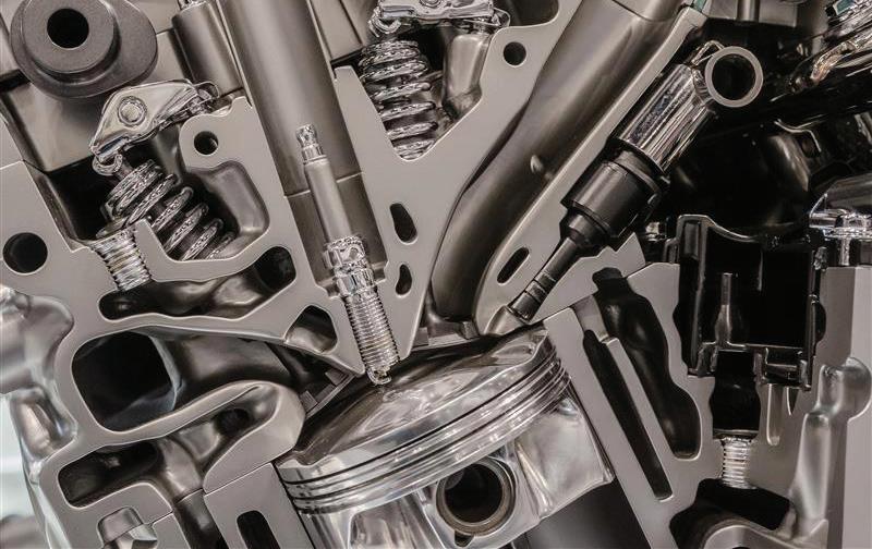
GASOLINE DIRECT injection has been a common feature on production vehicles for the past 15 years. GDI injects gasoline directly into the combustion chamber to aid in efficiency, power output, and a reduction of tailpipe emissions. VASYL S / SHUTTERSTOCK
Engine Break-In
Tips for safe starting a fresh engine
BY MIKE MAVRIGIAN
“BREAKING IN” AN ENGINE refers to precautions involving brand-new or rebuilt engines. Severe damage can occur if proper break-in procedures are ignored. In addition, properly lubricating the engine before it’s installed in the vehicle not only makes the task easier (due to better access) but also verifies oil pressure and allows you to check for fuel, oil, or water leaks. If the oil pressure is not adequate, addressing the concern is vastly easier with the engine out of the vehicle. Of course, a fresh engine may be fired for the first time while installed in the vehicle, but firing prior to installation verifies the condition prior to the arduous task of installation. If a problem arises, issues are more easily addressed with the engine out
of the vehicle.
Whether firing the engine in or out of the vehicle, never start a fresh engine without first circulating oil through the oil galleys to provide oil to the bearings and valvetrain. Even if the engine has been recently built or rebuilt, we need to ensure that oil is being delivered to all critical areas to avoid a potentially damaging dry-start.
Never assume that the engine’s oil pump will distribute oil through the engine’s oil circuit during cranking quickly enough to protect the bearings. For older engines that feature a distributor, it wasn’t uncommon to disconnect the coil wire, followed by cranking the engine, in order for the oil pump to build pressure. In theory,
this practice pulls oil from the sump and delivers oil, but it’s risky because oil may not be delivered quickly enough to protect the bearings. It will take even longer for oil to arrive at the rocker arms.
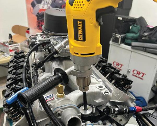
Priming the oil system is absolutely critical prior to starting the engine. This means sending oil to the main bearings, rod bearings, and to the entire valvetrain. Depending on engine design, this can be accomplished in one of two ways. If you’re dealing with an older generation engine featuring a distributor wherein the distributor engages the mechanical oil pump, you can remove the distributor and drive the oil pump using a drill and an adapter to drive the oil pump shaft. A heavy-duty drill (electric or pneumatic) can be used
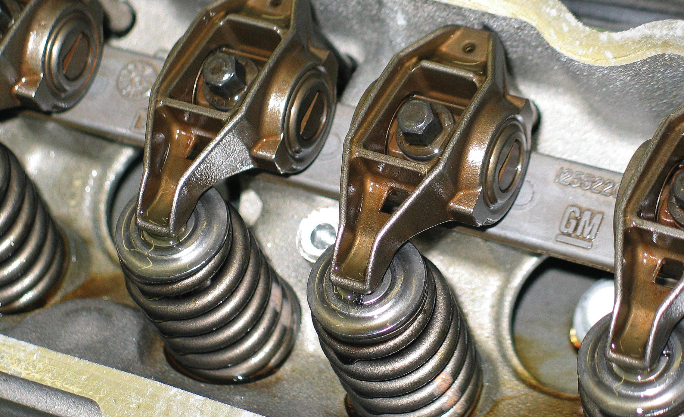
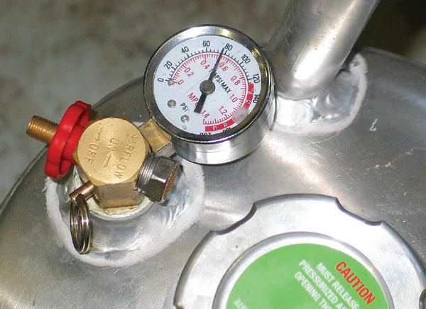
AS PRESSURIZED oil is forced into the engine, you will hear a gurgle noise as the oil begins to displace air. Continue pressurizing the system until you verify that oil is being delivered to the rockers.
PHOTO BY MIKE MAVRIGIAN
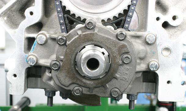
to turn the oil pump while you monitor a temporary oil pressure gauge. However, a preferred alternative involves the use of a pressurized oil tank, which can be used for any engine (distributor or distributorless). For engines that feature a crankshaft-driven/front-mounted oil pump (common today), using a pressurized pre-oiler is both convenient and efficient.
Pre-Oil Pump
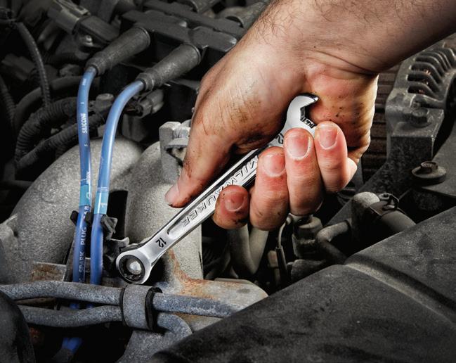
First, prepare the engine for pre-oiling. Add oil to the sump (a dedicated break-in oil is an excellent choice). Remove all spark plugs and remove the valve cover(s). Remove the oil pressure sensor and install a temporary oil pressure gauge. Locate an appropriate oil port for the connection of oil input from the pressure tank. Using the GM LS engine family as an example, there is an oil port on the block’s left side behind the front of the engine that is open to the oil pump. Also, select a wrench that allows you to manually turn the crankshaft.
Pre-Oiler Tankers
An engine pre-oiler system involves a portable pressure tank and a hose that connects the tank to the engine’s oil port. Add fresh oil to the tank, replace the tank’s fill cap, and pressurize the tank using shop air. When the tank’s valve is open, pressurized oil is forced into the engine via a connection hose between the tank and engine block. This is the easiest and by far the most efficient method of pressurizing the engine’s oil circuit.
Be aware that tanks are available in either steel or aluminum construction. Steel tanks are essentially the same type as those used for propane. If not stored properly with clean oil, rust can form inside the tank, which can lead to potential oil contamination. Steel or aluminum tanks will do the job, but aluminum tanks eliminate this concern.
How to Use a Pre-Oiler Tank
Hoses provided with these tanks are generally about eight feet long, allowing
you to place the tank securely on the shop floor or on a nearby bench. Remove the oil reservoir cap from the tank and add fresh, clean engine oil to the tank’s oil reservoir. Depending on the make/model of the pressure oiler, capacity can range from 4 to 12 quarts (generally, a minimum of about a 4-quart tank capacity will be enough to provide sufficient pre-oiling). Install the oil reservoir’s cap. Make sure that the pressure oil tank’s flow control valve is in the closed position.
Connect the tank’s outlet hose to the engine block. Make sure that the connection is secure. Lightly coating the adapter’s threads with Teflon sealant paste on the adapter threads is recommended to prevent potential leakage. Do not use Teflon tape, as loose “threads” of Teflon tape can potentially break loose and enter the system!).
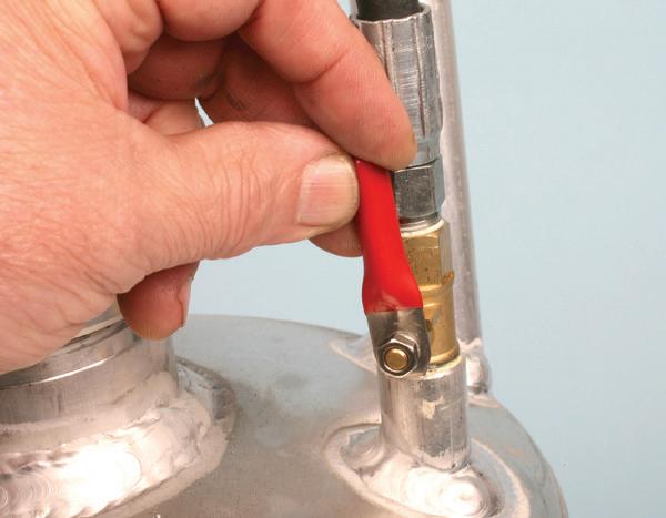
Using shop compressed air, charge the tank, and then disconnect the shop air. Once charged, connection to the shop air hose is no longer needed, making the tank portable. With the hose connected to the engine block, open the pressure oiler’s flow control valve to introduce oil into the engine. A “gurgle” noise will be heard as the pressurized oil begins to displace air. Pay attention to the rockers/ cam followers and verify that all rocker locations are receiving oil. Depending on the application, this may take as little as a few seconds to several minutes. Make sure that all rockers are receiving oil.
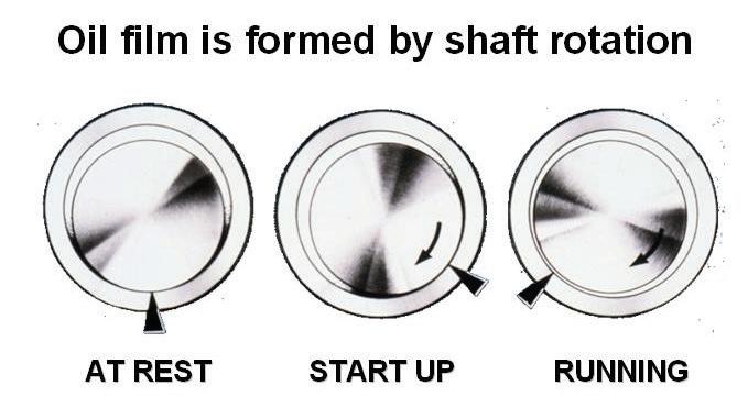
During the oil charge, slowly rotate the crankshaft at least 360 degrees. This provides a better opportunity for oil to push through the main bearing oil passages as journal oil holes pass by the bearing oil holes. Note that the crankshaft requires a supporting oil wedge between bearings and journals when running. Fully pre-oiling the bearings/journals provides added insurance.
Once you’re satisfied that oil has been thoroughly distributed, close the tank’s valve, remove the hose from the block, remove the pressure gauge, and install
PRE-OILING THE fresh engine is absolutely critical. PHOTO BY MIKE MAVRIGIAN
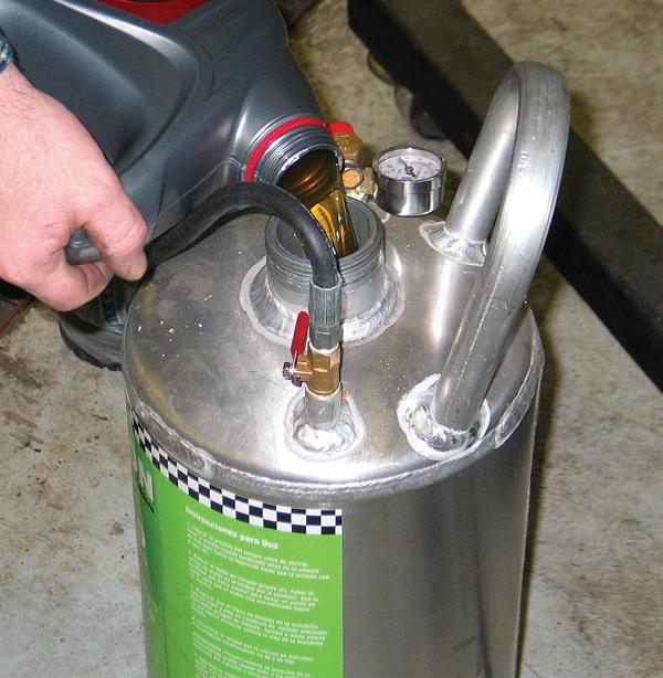
ADD BREAK-IN oil of choice to the tank. PHOTO BY MIKE MAVRIGIAN
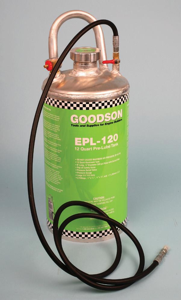
PRE-OILING PRESSURE tanks provide easy and efficient delivery of oil to bearings and valvetrain.
PHOTO BY MIKE MAVRIGIAN
the pressure sensor. Since you’ve injected oil into the system during pre-oiling, chances are good that the sump may be overfilled. Check the oil level and drain any excess oil. Depending on the engine application, you may wish to drain the oil sump and refill it with the oil intended for actual running.
Always use new spark plugs and verify that gaps are correct according to the engine maker’s specifications. Apply a
thin coat of anti-seize to the spark plug threads and torque to specification.
Tips
• It’s best to pre-oil the engine shortly prior to engine startup. In general, pre-oiling should take place no more than one or two days before firing
• For pre-oiling purposes, avoid heavy viscosities. You need to deliver oil efficiently. Generally speaking, avoid anything heavier than 10W-30.
• If the engine is newly built, consider avoiding the use of a full-synthetic oil for break-in, as this may prevent the piston rings from properly bedding against the cylinder walls. In many cases, it’s best to use a dedicated break-in oil for initial firing (an oil designed with the appropriate level of zinc phosphate).
• If the engine features a flat tappet camshaft (solid or hydraulic), you must run an oil with adequate high-pressure lubricant that contains sufficient zinc phosphate to avoid cam lobe and lifter damage. Specialty “high zinc” engine oils are readily available today that are specifically designed to provide the needed protection for flat tappet lifters/camshafts.
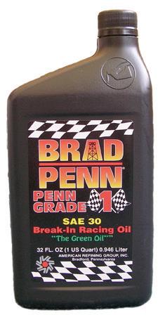
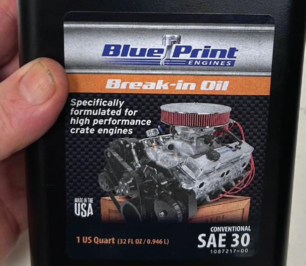
DEPENDING ON the application, a straight 30W break-in oil may be recommended. A dedicated break-in oil that features a high ZDDP formula (a high-pressure lubricant) will help to protect flat tappet cams and lifters. Even a roller-cam-equipped engine can benefit, especially if high-strength valve springs are present. Modern engines may require lighter cold viscosity ratings, such as 5W-20, to more quickly deliver oil to small oil orifices/passages for cam phasers, etc. If in doubt, for many of today’s production engines, it may be preferred to simply use the oil specified in the owner’s manual.
• High-pressure oil is also recommended if the engine features a roller cam coupled with high valve spring pressure, as higher valve spring pressures can promote wear on the rocker and valve tips. Most of today’s off-the-shelf engine oils feature greatly reduced levels of high-pressure zinc additives, so it’s important to select an oil that retains a high level of zinc phosphate. These specialty oils are now readily available from firms such as Brad Penn, Joe Gibbs, Lucas, Blueprint Engines, Royal Purple, Comp Cams and others. If the engine is a non-altered production type with a roller cam, these specialty oils won’t be necessary.
• Especially when starting off with a new or freshly rebuilt engine, it makes no sense to rely on used ignition components. Unless you’re certain about the condition, it’s advisable to install new coils, coil wires, and distributor caps/ rotors (where applicable).
• If the engine is carbureted, use only a “known good” carburetor for break-in, even if it’s not the carburetor you intend to finally install. This reduces the potential for having to fuss with richment settings, float levels, etc.
• If the engine features fuel injection, make sure that the injectors are working properly. If used injectors are to be installed, it’s recommended to first bench test.
• On engines that feature distributor ignition, pay careful attention to initial timing to avoid crank/no-start issues.
ONCE OIL has been added, install the fill cap and pressurize the tank using shop air. The tank is now portable and ready to connect to the engine block.
PHOTO BY MIKE MAVRIGIAN
DEDICATED BREAK-IN oils are readily available from a variety of suppliers.
PHOTO BY MIKE MAVRIGIAN
PHOTO BY MIKE MAVRIGIAN
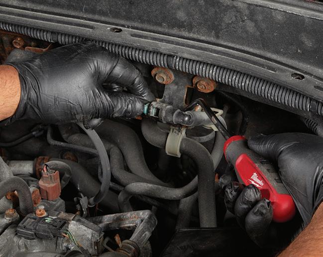
ONCE THE tank’s outlet hose is connected to the engine’s oil port, open the valve to allow oil to be forced into the engine. The spark plugs and valve covers must be removed. This allows you to view the rockers and to manually rotate the crankshaft.
PHOTO BY MIKE MAVRIGIAN
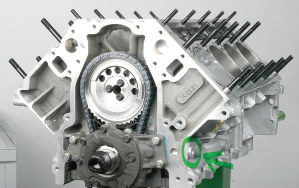
UNLIKE DISTRIBUTOR-EQUIPPED engines that can be primed by turning the oil pump shaft with a drill, many of today’s engines feature front-mounted, crankshaft-driven oil pumps.
PHOTO BY MIKE MAVRIGIAN
• Check all vacuum ports to make sure that all are connected appropriately.
• Make sure that the fuel tank has adequate fuel to avoid an unexpected engine shut-off.
• For distributor-equipped engines, make further timing adjustments as needed.
Flat Tappet Cams Caution
Granted, you’ll only encounter engines equipped with a flat tappet camshaft in “older” engines (mostly pre-1980s), but it’s wise to understand the required break-in procedures. Breaking in an engine equipped with a flat tappet camshaft requires added precautions to allow the lifters to properly mate with the camshaft lobes. Failure to follow these precautions can and will damage the cam and lifters. During break-in (which should last about 20 minutes), do not allow the engine to idle at low rpm. Make sure that the fuel supply and ignition are immediately ready for firing to avoid extended cranking. As soon as the engine fires, run at approximately 2,400 rpm for about 15 minutes, varying engine speed during the break-in period. Note that even if the engine features a roller camshaft, running the engine at varying speeds for a few minutes will help to promote piston ring seating. There is no lifter-to-cam break-in concern when dealing with roller camshafts and roller lifters, as long as oil is being delivered to the lifters.
During the first firing, carefully monitor engine oil pressure and temperature. When breaking in a flat tappet cam, it’s
CRANKSHAFT relies on the creation of an oil wedge during rotation. The weight of the crank rests on the lower bearing when the engine is off. As the crank rotates and oil is forced into the main circuit, the oil ramps under the crank, creating the wedge. During pre-oiling, slowly rotating the crank while pressurized oil is forced into the engine aids in thoroughly feeding oil as the journal oil hole passes by the upper main bearing oil holes. This is why the spark plugs are removed — to ease manual rotation of the crank. If the engine is not pre-oiled, initial crank rotation can result in a temporary dry condition and can easily damage the lower main bearings.
DON’T STOP after you see oil on only a few rocker arms. Pre-oiling is not finished until oil delivery to all rockers is verified.
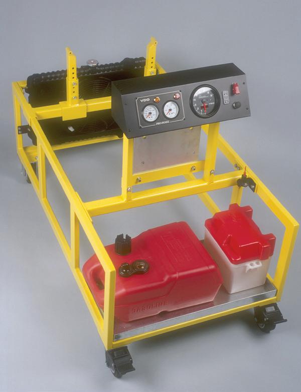
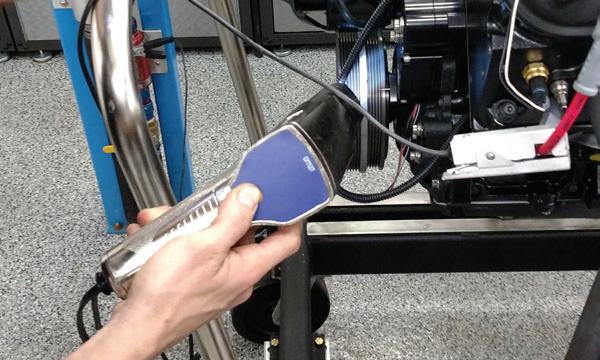
IF YOU opt to test-fire the engine on a test stand, the stand must be equipped with a radiator, fan, fuel cell, battery, ignition switch, a kill switch, and gauges to monitor rpm, oil pressure, and water temperature.
AN ALTERNATIVE to the use of a pressurized pre-oil tank involves turning the oil pump via a drill and adapter that engages the oil pump shaft. Of course, this only applies to a distributor-equipped engine where the cam gear engages the distributor gear and rotates the oil pump. If a drill is used, a high-powered electric or pneumatic drill is required.
PHOTO
MIKE MAVRIGIAN
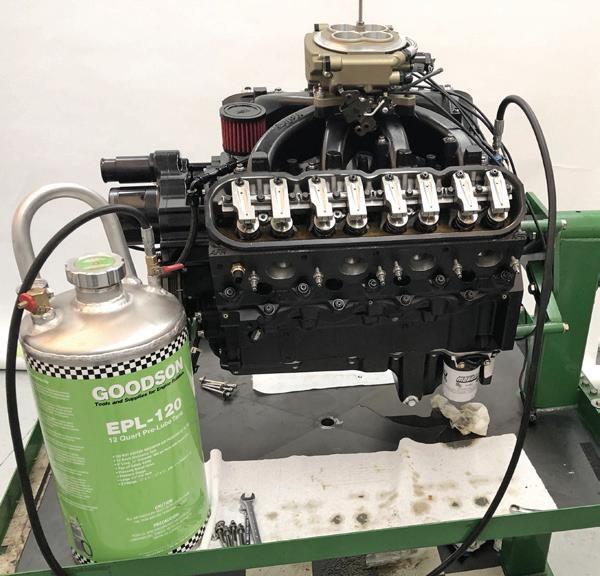
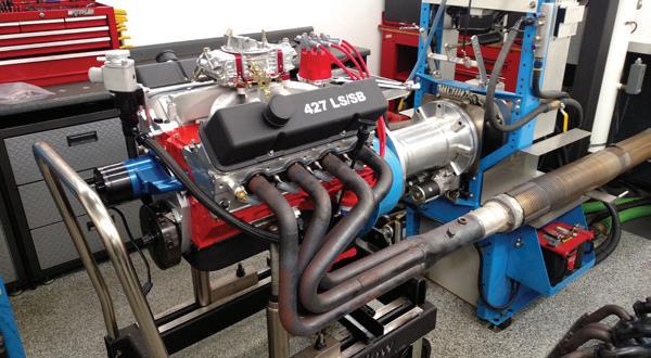
WHILE IT may seem like overkill, a fresh engine can be test-fired for break-in on an engine dynamometer. Of course, this may or may not be a practical solution for all shops.
OF how the
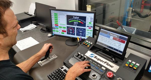
IF THE engine is “broken in” on a dynamometer, all engine operating data is easily viewed and recorded, including but not limited to engine speed, water temperature, oil pressure relative to rpm, airflow, fuel pressure, ignition curve, air/fuel ratio, etc., all at a controlled ambient temperature and atmospheric pressure. Of course, horsepower and torque data are also available. While that may or may not be of primary concern for a customer’s engine, the data verifies that the engine performs as desired.
USING THE GM LS platform of engines as one example, an access port exists that allows pressurized oil to be forced directly into the oil pump (see port plug circled).
PHOTO BY MIKE MAVRIGIAN
THE
BY
PHOTO BY MIKE MAVRIGIAN
PHOTO BY MIKE MAVRIGIAN
REGARDLESS
engine is test-fired, use the opportunity to check ignition timing.
PHOTO BY MIKE MAVRIGIAN
PHOTO BY MIKE MAVRIGIAN
PHOTO BY MIKE MAVRIGIAN
important that the engine is not stopped at any point during the procedure.
If you opt to fire the engine before vehicle installation, there are two basic options. A portable live-fire test stand or on an engine dynamometer. A test stand should be equipped with a method to bolt the engine to the stand (at motor mount locations and at the rear of the block. The stand should be equipped with a radiator, a fuel cell, a battery, an ignition switch, and a minimum of critical gauges, including oil pressure, water temperature, and engine rpm. Install the appropriate starter. The flywheel or flexplate must be installed, especially if the crankshaft features internal balance. Exhaust will include an exhaust manifold (or tubular headers) and exhaust tubing that extends for at least 36 inches. Test stands may be fabricated or purchased as a complete kit. If you’re planning to run the engine on a test stand, be sure to provide adequate airflow via a large electric fan mounted to the radiator and a large floor fan. Avoiding the potential for an overheating condition is critical.
Whether you plan to run the engine on a test stand or in the vehicle, plan ahead for potential problems by having at least one fire extinguisher handy, as well as heat-resistant gloves, eye protection, and a face mask. Avoid performing the job alone. A
minimum of two technicians should be available: one to operate the controls and one to monitor gauges and check for leaks or other issues.
An alternative, though more costly, is to fire the engine on an engine dyno. Since your shop likely is not equipped with this, the work can be farmed out to a local performance engine builder. A dyno session cost will vary, but should be in the range of $1,000 or so. Engine dynos are commonly used to verify engine operation in addition to horsepower and torque (and tuning). While seemingly overkill, a dyno can be used for basic break-in and to verify condition.
With that said, if you wish to keep everything in-house and avoid the use of a test stand, it’s certainly acceptable to perform the initial firing with the engine in the vehicle, provided that you have previously oil-primed the engine.
After-Run Engine Checks
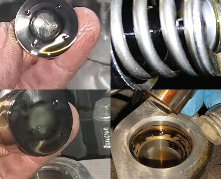
Once the initial break-in has been accomplished, immediately drain the engine oil into a clean plastic drain pan and remove the oil filter, but do not discard the filter. On a workbench, cut the filter apart (dedicated oil filter cutters are readily available), remove the filter element, and inspect all filter surfaces/pleats. Evidence of notable metal debris found in the filter is cause for alarm, as this may indicate bearing damage.
Run a clean magnet through the oil drain pan, checking for slivers/debris. If the oil and filter checks confirm no issues, refill the sump with an oil of your choice and install a new filter.
Depending on the application, it is advised to drive the vehicle for about 100 to 500 miles before the next oil and filter change. At least for the first 100 miles or so, avoid constant highway speeds, opting for varying engine speeds. This can further promote proper piston ring seating and “seasoning” of the new valve springs. Routinely check coolant levels after each engine stop and complete cool-down. Note
that if multi-layer steel head gaskets are installed, in some cases, you might witness very slight external water weeping between the heads and block. This may be normal. Once the factory-applied gasket’s sealant cures, this weeping will stop (usually within about 20 minutes from first firing, if it occurs at all). Also, routinely inspect for potential external oil leaks.
Engine Pre-Oiler Tank Sources
Goodson Tools
156 Galewski Dr. Winona, Minnesota 55987 800-533-8010 goodson.com
EPL-120
• 12-quart capacity
• Lightweight aluminum construction (eliminates potential rust inside the tank)
AFTER THE initial “break-in” run, drain the oil into a clean plastic drain pan and inspect for debris. Cut the oil filter open and inspect every pleat in the filter media, both visually and with a magnet. Inspecting the used filter can be very informative. If the filter element is clean, that goes a long way to make you feel more confident about engine condition.
PHOTO BY MIKE MAVRIGIAN
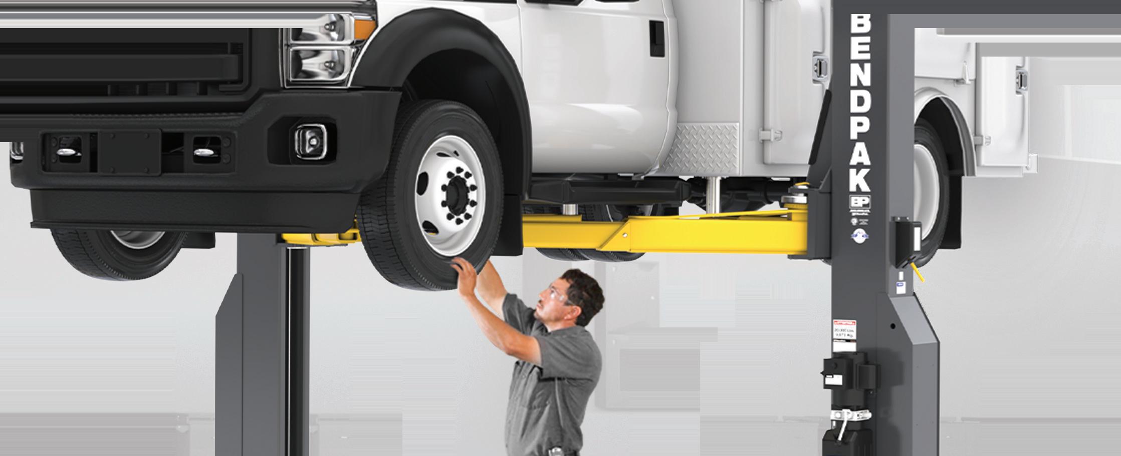
A versatile choice for mixed fleets, BendPak’s new 16AP and 20AP Series heavy-duty two-post lifts easily take on Class 1 through 5 vehicles, from passenger cars to commercial trucks and vans. They reach further, lift higher and deliver greater stability than other lifts, all while protecting technicians with unmatched safety systems and ergonomics. With fewer moving parts, they’re easier to maintain, less prone to wear, and more cost-effective to operate. Maximize your uptime and efficiency with BendPak’s heavy-duty lifts — delivering superior performance and unmatched value. To learn more or to shop now, visit bendpak.com or call us at 1-800-253-2363
Modern GDI: What technicians need to know
Understanding GDI’s complexities — including injector design, spray patterns, and carbon buildup — is crucial for effective diagnosis and maintenance, especially as these systems become more prevalent in vehicles
BY JEFF TAYLOR
IN THE LAST 20 YEARS, gasoline direct injection has changed how fuel delivery works in modern engines. GDI improves power, emissions, and economy, but these benefits come with issues. These systems come with a growing list of quirks, service needs, and drivability concerns that we’re seeing more of in the shop.
What Makes GDI Different?
The basic idea behind GDI isn’t all that complex. GDI systems fire the fuel straight into the combustion chamber, and they do it under some serious pressure. That direct approach gives the PCM a lot more control over when and how much fuel gets delivered, even allowing multiple injection events during a single cycle.
To make that work, a GDI system needs to operate at a much higher pressure than older port systems. Typical GDI rail pressures range from 500 to 3,000 psi (34 to 200 bar) depending on engine load and RPM. Sustaining and dealing with that kind of fuel pressure requires a low-side electric fuel pump, a cam-driven high-pressure fuel pump mechanical pump, pressure sensors, solenoids, control circuits, and a feedback loop. Bosch is now producing HPFP pumps capable of producing over 5,000 psi (350 bar).
GDI injectors require significantly more voltage than traditional port fuel injectors to function due to the higher fuel pressures involved. Instead of 12 volts, they are typically supplied 60 to 70 volts to op-
erate, supplied by internal PCM capacitors (some older BMWs used 200 volts for their piezo injectors).
This is important to remember because standard solenoid lights or test lights won’t detect injector drive issues, and diagnosis requires a scope or current probe. Testing GDI injectors requires a different approach than PFI. These systems use a peak-and-hold strategy, where current can spike up to 12 amps to quickly overcome chamber pressure and open the pintle. After opening, the PCM drops the current to around 2.5 to 5 amps to prevent coil overheating while holding the injector open. On the scope, you’ll see a sharp current ramp at injector command, followed by a plateau (hold phase), and a distinct drop when the pintle closes.
GDI systems also demand a different diagnostic mindset. You’re no longer just watching short- and long-term fuel trims. Now you need to be reading high-side versus low-side pressure, injector pulse strategies, pump control duty cycles, and desired versus actual data to confirm system operation. Even with all of that, you may still end up tracing a fault back to something as seemingly unrelated as a sticking PCV valve or a worn timing chain.
The Heart of the System:
Low and High Side Fuel Delivery
The GDI fuel system has two main sides: low pressure (supply) and high pressure (delivery). On the low side, an electric pump in the tank sends fuel to the high-pressure mechanical pump. It’s usually controlled by a fuel pump module or a PCM-integrated driver. Pressure typically ranges from 50 to 80 psi. Some platforms include a low-side pressure sensor. Others don’t, so you’ll need scan tool data, duty cycle, or current ramping to verify operation. Strategies vary: Ford often uses PWM voltage control, while GM, Toyota, and others now use 12-volt threephase brushless (BLDC) pumps.
On the high side, a cam-driven pump uses a solenoid to regulate pressure and volume in a closed-loop system. The PCM monitors fuel rail pressure and adjusts the solenoid’s duty cycle to match demand. These solenoids are low-resistance (≈ 0.5 ohms) and pulse-controlled around 4,000 Hz. When energized on the pump’s upstroke, pressure rises. A check valve holds pressure when it’s off. Use an amp clamp and scope to verify signal integrity, and remember that amperage only confirms control, not mechanical function.
Always match actual versus desired pressure, and check both low and high sides. Don’t overlook the mechanical pressure relief valve in the pump or rail (it’s a failsafe). If rail pressure drops without a duty cycle change, the relief valve could be weak or stuck. In some VW and Hyundai GDI systems, fuel rail pressure sensors are known to drift over time. If you’re seeing erratic
pressure readings or codes like P0087/ P0088 with no obvious cause, consider a sensor offset issue before replacing pumps or injectors.
If you’re replacing the HPFP, inspect the cam follower and lobes. GM uses a 3-lobe cam; Ford and VW use a 4-lobe cam. Reinstalling a pump on worn components will cause premature failure and pressure issues all over again. Always depressurize the system before disconnecting high-side lines. Even at idle, GDI rail pressure can exceed 500 psi. Always use a torque wrench and follow OEM tightening sequences, as some pumps require angle torque to avoid body distortion.
GDI Injection Modes
GDI engines switch between several injection modes depending on load and RPM. At light throttle and low speed, many systems run a stratified charge super lean, sometimes up to 40:1, by aiming fuel directly at the spark plug for proper ignition. Under load, the PCM shifts to a more traditional homogeneous mode (14.7:1), with fuel distributed evenly throughout the cylinder.
Cold starts trigger a catalyst heating strategy, where the PCM fires an early injection to start combustion and a secondary shot to heat the light-off catalyst. Some platforms go further, combining an intake-stroke vaporizing spray with a richer compression-stroke shot to ignite leaner air-fuel mixes. This split injection approach is used by Toyota’s Dynamic Force engines, Hyundai Smartstream, Mazda Skyactiv, and GM’s Ecotec Gen III, all of which use dual injection events per cycle. It helps improve combustion efficiency, cut emissions, and reduce NVH, especially during cold starts and low-load cruising. A distorted spray pattern caused by deposits can skew air-fuel mixing, especially in stratified mode, where combustion relies on precise targeting near the spark plug.
All of this is PCM-controlled and varies by OEM, which is why understanding the injection mode matters. A lean fuel trim during cold idle might be by design. A rich condition under light load could be part of a warmup strategy. Without knowing what mode the engine is in, your scan data could lead you down the wrong path.
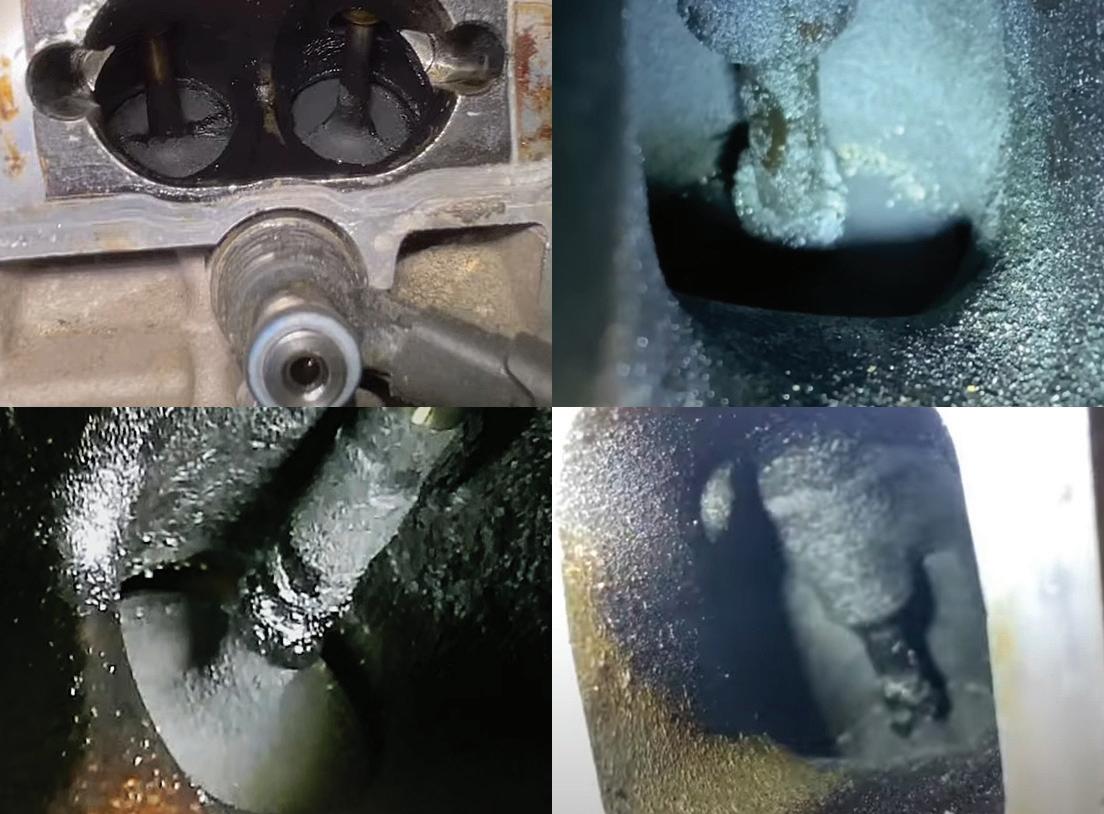
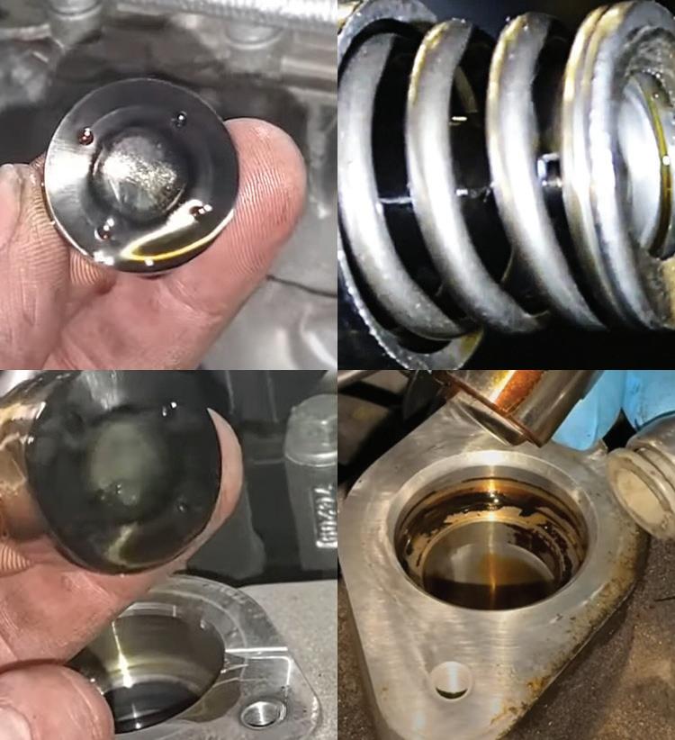
EXAMPLES OF heavy carbon buildup on intake valves from GDI engines. With no fuel wash across the back of the valves, oil vapors and blow-by gases form stubborn deposits that restrict airflow, disrupt atomization, and lead to drivability complaints.
PHOTO BY JEFF TAYLOR
Injector Design, Spray Patterns, and Deposits
GDI injectors are built to handle the heat and pressure inside the combustion chamber, and they’re sealed off with a Teflon ring to keep combustion gases from blowing past the injector tip and causing problems. Newer GDI setups use split injection and multi-hole tips for better combustion. Engines with cylinder deactivation can still see heavy carbon in the shut-down cylinders, especially if they don’t reach temperature on short trips.
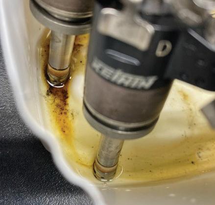
HONDA GDI injectors soaking in cleaner solution. Even with extended soaking, baked-on carbon at the nozzle tip is rarely dissolved. Most deposits require injector replacement to restore proper spray pattern and fuel delivery.
JEFF TAYLOR
BY
PHOTO
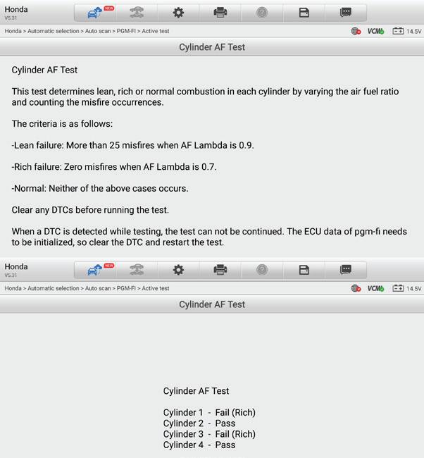
HONDA CYLINDER AF Test in action. This scan tool routine varies commanded air-fuel ratio and monitors misfire counts to identify lean or rich combustion per cylinder. In this case, Cylinders 1 and 3 failed rich, while 2 and 4 passed — pointing toward a fuel imbalance issue often associated with P219X codes.
PHOTO
BY
JEFF TAYLOR
Because GDI injectors are exposed directly to combustion, they are prone to heat soak and deposit formation. The issue here is not just soot buildup. The concern involves varnish and waxy olefins that form during hot soak conditions. These deposits can affect spray pattern, droplet size, and overall injector flow rate. What you end up with is usually a random misfire, a stumble when you hit the gas, or a rough start when cold. It might not set a code, but the customer will feel it.
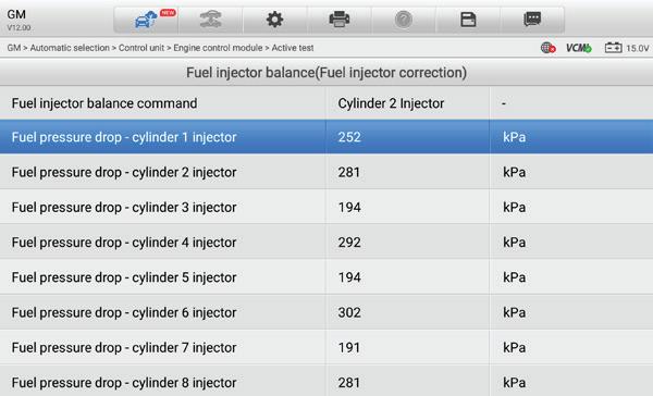
GM INJECTOR balance test results. Each injector is pulsed individually, and the fuel rail pressure drop is measured. Consistent drops across cylinders indicate balanced fueling, while low values (such as cylinders 3, 5, and 7 here) suggest restricted or underperforming injectors.
PHOTO BY JEFF TAYLOR
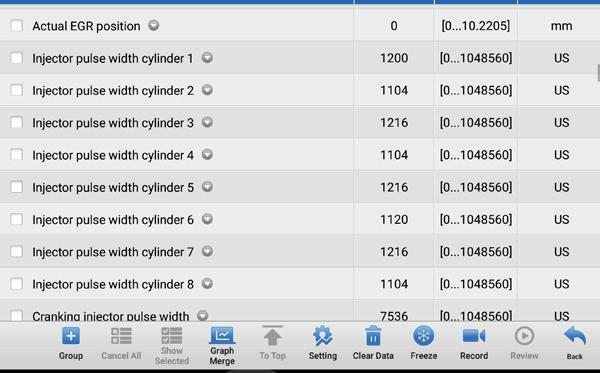
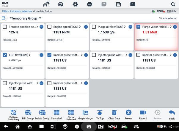
THIS SCREENSHOT from a 2019 GMC Sierra 5.3L displays Injector pulse width data by cylinder. Most cylinders command between ~1100–1216 µs, indicating relatively balanced fueling. Significant deviations from this pattern would suggest a cylinder-specific fueling issue.
PHOTO
BY
JEFF TAYLOR
Injector balance tests, especially those using scan tool command or pressure drop measurements, are crucial here. Mode 06 data and power balance readings can help isolate the problem cylinder, but only if the PCM logic is detailed enough to capture it. Don’t assume that fuel system cleaners or additives will clear these deposits. They might, but most modern GDI injector fouling requires mechanical /ultrasonic cleaning or outright replacement.
Fuel Dilution: A Hidden Threat
One of the most serious long-term issues with GDI engines is fuel dilution of the engine oil. Direct injection allows fuel washdown into the crankcase, especially when cold. This raises the oil level, reduces viscosity, and over time, compromises the oil’s ability to protect the engine. Short-trip driving and stop-start systems, which prevent the engine from reaching full operating temperature, can increase carbon deposit formation and contribute to fuel dilution.
Earlier versions of Honda’s 1.5-liter Earth Dreams turbocharged GDI engine (used in CR-V, Civic, and Accord) suffered from this issue, especially in cold climates or with short-trip driving. The engine may not reach full operating temperature, leading to incomplete combustion and fuel washdown. Honda developed a software update to adjust the warm-up strategy and reduce injector-on time during cold starts.
GM and Ford have all issued software updates and procedural recommendations to combat fuel dilution, including extending warm-up times, revising fuel control logic, and recommending more frequent oil changes.
As a technician, one of the first things to check when diagnosing a rich code, rough idle, or PCV-related concern is the oil dipstick. If the oil smells like fuel or is significantly overfull, you may be dealing with an oil dilution problem. And in those cases, changing the oil isn’t just a good idea, it’s essential before continuing the diagnosis.
If you’re chasing a P219A or P219B code (rich imbalance by bank), monitor key-off
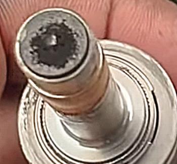
THIS SHOWS a Honda GDI injector with carbon accumulation on the nozzle tip. Deposits like these can distort spray patterns, reduce fuel atomization, and contribute to misfires, fuel trim issues, and drivability complaints.
PHOTO BY JEFF TAYLOR
fuel pressure retention. A bleeding injector or leaking high-pressure pump can be confirmed by how quickly pressure drops after shutoff. Ideally, GDI systems should hold pressure for at least five minutes.
Carbon Deposits and Intake Valve Cleaning
Since GDI injects fuel directly into the chamber, there’s no natural cleaning of the intake valves like in port systems. Combine that with leaner combustion, higher compression, and aggressive valve timing, especially in turbo engines, and you’ve got a recipe for carbon buildup. During valve overlap, hot exhaust gases enter the intake tract, carrying soot that sticks to oil from the PCV system. Once it bakes on, it’s there to stay. BMW and VW build up faster, while GM and Ford resist longer, but all eventually misfire cold or set P0300s.
Where Carbon Forms Really Matters
Combustion chamber buildup is thin and dense, but valve deposits are soft, thick, and porous, perfect for disrupting airflow and atomization. Even a light coating can cause drivability issues. Engine oil also plays a role not just through PCV vapors, but from additives like friction modifiers designed to protect the HPFP cam follower. These can bake onto hot valves and form stubborn deposits. Carbon in the ring lands restricts movement and reduces compression. Cold soak cleaning can restore 20 to 30 PSI.
To fight this, some OEMs now use dual injection setups combining GDI with port fuel injection. Toyota, Ford, and Hyundai use this to wash the valves at low rpm, then switch to GDI under load. It works well, but not every platform has it.
Carbon chemistry varies by fuel blend, oil type, combustion temp, and drive cycle, so no single cleaner works for all engines. Ethanol-blended fuels (E10/E15) tend to worsen varnish and olefin buildup. While some deposits respond to chemical cleaning, others require walnut blasting. The key is getting the cleaner to the valve. Older methods of spraying ahead of the throttle often
fall short as the product pools or sticks just behind the throttle plate. Large droplets pool and miss valves; vacuum methods also fail to atomize. Newer delivery tools atomize the cleaner using an injector-type device after the throttle body, so it can follow the airflow into the ports and attach to the carbon on the valves. Remember, if it doesn’t reach the valve in the proper form, it won’t work, no matter how good the product is.
If you’re chasing cold-start misfires that clear with engine temp, intake valve carbon should be high on your list.
Manufacturer-Specific GDI Issues
Ford has recalled a wide range of 2020–2024 SUVs, including Bronco Sport and Escape, for cracked high-pressure injectors. Some allow raw fuel to leak externally, increasing fire risk and triggering check engine lights. Ford’s temporary software patch alerts drivers to pressure loss, but a mechanical fix is still pending. These vehicles share GDI and TGDI hardware with F-150 models, and the symptoms are nearly identical: misfires, lean/rich conditions, and fluctuating fuel pressure. If you’re not watching both lowand high-side values in real time, these faults are easy to misread.
The 2024–2025 Ford Ranger with the 2.3L TGDI engine isn’t under recall yet, but fuel dilution has become a concern. Oil samples are coming back with 5% or more fuel after only a few thousand miles. The
cause appears to be short-trip cycles and poor warmup, allowing fuel washdown. No official TSB exists yet, but the pattern is familiar. Until Ford acts, shops should be checking oil levels and smell during engine complaints, especially if fuel trims or injector balance seem off.
GM issued TSB 20-NA-197 after P0191 started showing up on some Silverado and Sierra models, not because of a bad sensor or pump, but due to a poor connection at the fuel rail pressure sensor. Before replacing parts, check the connector for corrosion, clean the terminals, apply dielectric grease, and verify pin tension. If rail pressure looks stable on live data, this simple fix can save time, money, and a misdiagnosis.
Honda’s 1.5L turbocharged GDI engines
PHOTO BY JEFF TAYLOR
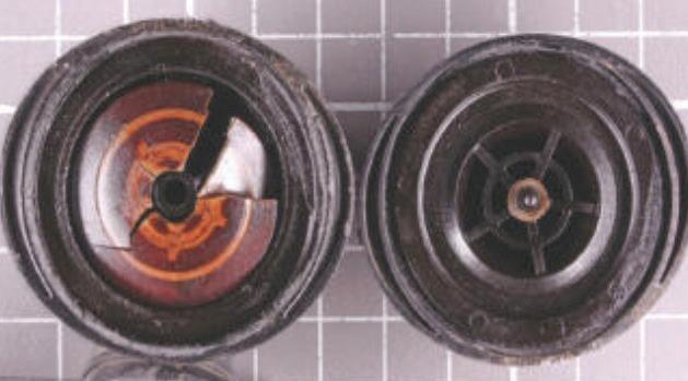
EXAMPLES OF high-pressure fuel pump follower and bucket wear. Fuel dilution and improper maintenance accelerate scuffing and pitting, which can lead to pump efficiency loss, pump failure, or camshaft lobe damage if left uncorrected.
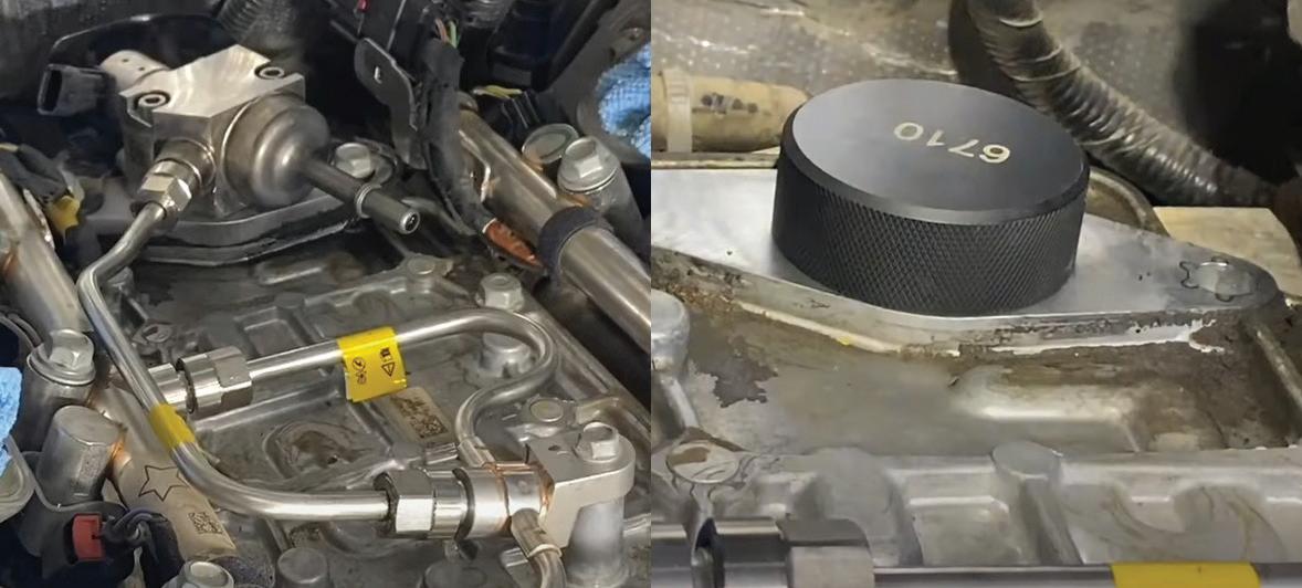
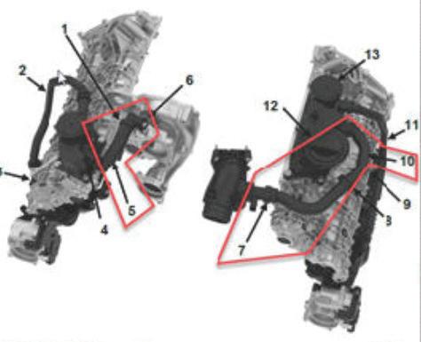
WHEN REPLACING a GDI high-pressure fuel pump, always follow service information, ensure the camshaft is on the flat (base circle), and torque the pump and fuel line fasteners to specification. On many GM engines, a special tool sits flush with the cover to confirm the correct cam position before installation.
PHOTO BY JEFF TAYLOR
have shown their own set of problems, mostly tied to running excessively rich and cylinder imbalance. Codes like P0172 (system rich), P219E (cylinder imbalance), and random misfires across multiple cylinders are common, usually along with chugging under load or hard starting. Fuel pressure and MAF may look normal, ignition may check out, yet the PCM still sees an imbalance.
The root cause in many of these cases ends up being injector contribution. Honda’s PCM uses cylinder fuel factor testing to measure how much correction each hole needs, and when one or more injectors start over-fueling, those values will fall outside the normal 0.83 to 1.15 range. You can often prove it in the bay by swapping injectors and watching the imbalance follow. That’s why replacing plugs, A/F sensors, or even updating software won’t solve it — the injectors themselves are drifting rich while everything else still looks “in spec.”
The fix is usually new injectors along with a PCM reset and crank relearn. Honda stresses the relearn because accurate crank indexing is critical for misfire detection, and without it, the PCM may keep flagging ghost misfires. Once new injectors are in and the relearn is complete, fuel factor and AF tests settle back into range, and the drivability clears up. The key takeaway: when you’re chasing rich codes and imbalance on Honda’s 1.5T, don’t get lost in fuel trim data or sensor swaps — go straight to injector testing, because that’s where the fault often hides.
Hyundai and Kia GDI engines, especially the Theta II 2.0L and 2.4L, also have a history of fuel dilution under cold-start and short-trip use. Check for fuel odor or rising oil level before digging into drivability concerns. These engines also suffer from intake valve carbon buildup, with misfires and idle issues often appearing around 30,000 miles, even with good maintenance. The newer Smartstream engines are improved, but early imbalance and mild dilution are still showing up in 2.5L TGDI models. Whether you’re chasing a lean code or a misfire, oil
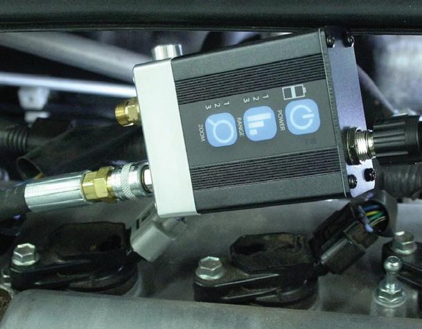
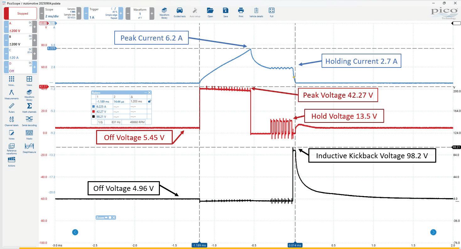
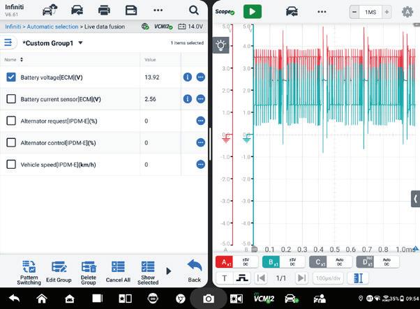
THIS WAVEFORM shows the electrical activity of a GDI fuel injector during operation. Current flow (blue trace) ramps up to a peak of 6.2 amps, then settles at a holding current of 2.7 amps once the injector pintle is fully lifted. On the voltage side (red trace), the driver initially applies a peak voltage of about 42 volts to overcome the injector’s mechanical inertia, before reducing to a hold voltage of 13.5 volts to keep the pintle suspended with less energy. When the injector is switched off, the magnetic field inside the coil collapses and generates an inductive kickback voltage spike of nearly 100 volts (98.2 volts shown here). This spike is a normal byproduct of coil collapse and is managed by the driver circuitry inside the PCM. If not properly controlled, these spikes could damage the injector driver. This pattern illustrates the peak-and-hold strategy used on most GDI injectors: a high initial current and voltage to open the injector quickly, followed by a lower holding level to reduce heat and power demand. The final sharp voltage rise at turn-off (coil collapse) confirms the injector coil is intact and behaving as expected.
PHOTO BY JEFF TAYLOR
condition, intake valve cleanliness, and injector contribution should all be part of your diagnostic process, even if no codes are set.
Diagnostics: Scopes, Scan Tools, and Safety
Diagnosing GDI problems requires more than just a scanner and a code reader. You need to understand both sides of the system, be able to command components, and, in many cases, verify pressures manually. Always compare desired versus actual high fuel rail pressure and allow stabilization time at idle before recording data. If you’re getting a P0191 code (fuel rail pressure sensor performance), be aware that each manufacturer has slightly different criteria for what that code means. For example, GM may log it if desired and actual fuel pressures differ for more than three seconds; Ford uses a 20-psi delta for eight seconds.
High-side fuel pressure testing should also include assessing the HPFP pumps’ reserve capacity by commanding it to exceed expected load pressures and watching to see if it can deliver. The HPFP reserve capacity refers to the pump’s ability to exceed fuel
pressure demand under load without maxing out its control duty cycle. To check HPFP reserve capacity, technicians should monitor actual fuel rail pressure versus desired fuel rail pressure during a snap throttle or high-load event. If the HPFP can meet or exceed demand without maxing out the duty cycle, it’s got good reserve capacity. But, if pressure lags while the solenoid command is near 100%, the HPFP may be maxed out, failing, or possibly there is a low-side restriction or low-pressure supply pump issue.
Final Thoughts: GDI isn’t going anywhere; it’s in everything from small cars to full-size trucks and hybrids. The systems are getting more advanced, and so are the problems. To diagnose them properly, you need to understand how the whole system works, not just the basics. That means using scope data, checking both sides of the fuel system, and knowing what to look for when symptoms show up. Whether it’s fuel in the oil, a lazy injector, or a random misfire, it comes down to knowing where to start and what to rule out. And with GDI strategies changing through software updates and new hardware, staying current is just as important as knowing how it all works.
Whether you’re a seasoned technician or just starting in the industry, our Gold video library has everything you need to stay ahead of the curve.
Unlock over 60 hours of advanced, in-depth automotive training with our Gold video library. Featuring recorded webinars led by industry experts, this comprehensive library covers cutting-edge diagnostics, complex repair techniques and the latest innovations in automotive technology. With new content added monthly, you’ll stay up-to-date on emerging trends and tools, ensuring your skills remain at the forefront of the industry.
Learn from industry experts through our extensive library of recorded webinars covering essential topics—from advanced diagnostics to the latest automotive technologies. With flexible subscription options, you can access top-tier content when it works best for you.
Subscription benefits
Access to our Free video library
Access to our Gold video library
Webinar handouts
Discounts for live events, including our DTC Annual Event
Swag and other giveaway items Sign up now
Every day, professionals and DIYers trust their lives to vehicle lifts. But the web is flooded with offshore resellers pushing uncertified, no-name lifts with bold claims — no proof, no oversight, no accountability.
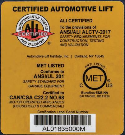
BendPak certified lifts meet ANSI/ALI ALCTV (current edition), the only nationally recognized lift safety and performance standard. Only certified lifts carry the ALI Gold Label and appear in the official ALI Directory, proof of third-party testing and validation.
At BendPak, safety is engineered into every lift. Built strong. Certified tough. And every Gold Label tells the story.
If you’re lifting cars and putting people under them, nothing matters more than safety. Don’t risk it on unverified imports. Get the lift that’s certified. Get BendPak.
Demand the Gold Label. Trust BendPak. Call 1-800-253-2363 or
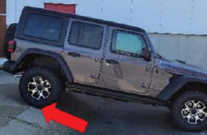
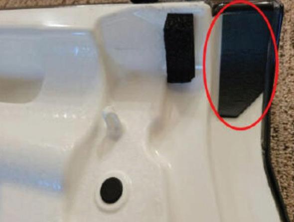
Solved: 2008 Jeep Wrangler 3.8L, P0340 + P0344
From October 2025, Motor Age
BY BRANDON STECKLER // Technical Editor
A CLIENT OF MINE WAS FACED WITH a 2008 Jeep Wrangler with a 3.8L engine. For unknown reasons, the engine was previously replaced with three different units, and at least one replacement PCM.
Given this information, what would you do next?
• Fix the wiring first and re-examine
• Replace the CMP sensor and re-examine
• Condemn the CMP reluctor for improper configuration
• Inspect the CMP reluctor with a borescope
For those of you who chose answer No. 1, congratulations! The shoddy wir -
THE DATA DOESN’T LIE
WELCOME BACK TO ANOTHER EDITION OF “THE DATA DOESNT LIE,” A REGULAR FEATURE, WHERE I POSE A PUZZLING CASE STUDY.
ing repair is something to correct before continuing further. Even a positive test result at the time of testing may be an intermittent loss of continuity under other operating conditions.
Answer No. 2 is not correct. Although a faulty CMP sensor could cause the symptom, we would need further evidence to responsibly condemn. Further testing would be required, and with the poor circuit conditions already dis -
covered, it would not be a recommended path to travel.
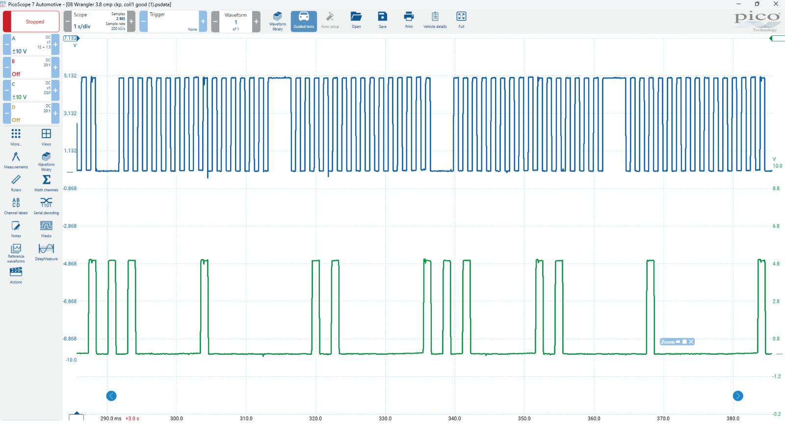
Answers No. 3 and No. 4 are logical answers. As I noticed that the captured correlation waveform from this vehicle was certainly suspect, examining the CMP reluctor would not be an illogical thought, especially since the faulted pattern seemed to repeat. There was an excellent chance that this remanufactured engine was either assembled with the wrong CMP reluctor or the reluctor had damaged/bent teeth. We chose to repair the wiring first and then re-evaluate. The chosen path paid off. Repairing the wiring left the vehicle fault-free (Figure 1).
BRANDON STECKLER is the technical editor of Motor Age magazine. He holds multiple ASE certifications. He is an active instructor and provides telephone and live technical support, as well as private training, for technicians all across the world.
EV essentials all techs need to know
What basic EV repair knowledge do techs need to work on EVs, and why now?
BY CRAIG VAN BATENBURG
BEFORE YOU START READING this article, a relatively new acronym is xEV. This is what ASE calls a hybrid, plug-in hybrid, and pure electric vehicle (HEV, PHEV, and EV). Almost every electric vehicle training class you attend at a hotel ends up being a safety class, plus some tips.
That is not a complaint about the industry, but an observation. I hear from many well-trained technicians that they want more. What do you need? Let’s start with a five-gas analysis class. Do you know the science that started the move to cleaner cars in model year 1975? If not, it’s time to
study chemistry again or maybe for the first time. More about that later.
What Do We Mean By “Essential Skills?”
One definition is “absolutely necessary; extremely important.” Let’s go with that one. Could that apply only to safety and
COLLEGE CLASS getting the industry ready to address xEVs.
PHOTO BY CRAIG VAN BATENBURG
emissions? What about performance or eventual safety problems? This gray area represents many things to many people. “Just keeping it on the road” may be too low a bar for most.
Assuming you attended an automotive technical college and received an associate’s degree in modern internal combustion 12-volt vehicles, let’s take a look at what you learned about xEVs in college. For many of you, that answer is “nothing.” That learning would have changed your outlook. After automotive classes in high school, most colleges would have you trained and tested in eight areas that ASE defines as: Engine Repair, Automatic Transmission/Transaxle, Manual Drive Train and Axles, Suspension and Steering, Brakes, Electrical/Electronic Systems, Heating and Air Conditioning, and Engine Performance. Your education in those areas allowed you to service and repair the entire car or truck. What if your school offered an equivalent degree in electric vehicles? Here is one view of that scenario.
Looking at our list of eight areas, we will rename them for an EV technician. Engine Repair is now 3-Phase Motor Repair. Automatic Transmission/Transaxle becomes a 1-Speed Gearbox and Axles, so Manual Drive Train and Axles is no longer relevant. Suspension and Steering is still the same. Brakes becomes Regenerative Braking Systems. Electrical/Electronic Systems is still the same name, but involves much higher voltage and current levels. Heating and Air Conditioning is Thermal Management, and Engine Performance is obsolete.
We need to add more categories: High-Voltage Battery Systems would be a new test, while Inverters, DC-DC Converters and Grid Charging may be included in Electrical/Electronic Systems. Using these new ASE future tests (I am predicting a lot here), let’s examine what you will need to sharpen your skills and maybe learn some new
ones. We will focus on pure EVs and why they are here.
No. 1: Three-Phase Motor Repair
There are three types of motors in use today: a 3-Phase Brushless Permanent Magnet Synchronous Motor, a 3-Phase Brushless Induction Asynchronous Motor, and a new type, the Brushed Externally Excited Synchronous Motor that Nissan developed recently. The learning is relatively straightforward. Rotors rarely fail quickly, but the stator may. The test equipment costs less than $1,000. Repair work can be done on most motors, but it is not needed often, as they are simple and well-made. What drives the motor — an inverter — will be included elsewhere. The motor is also a generator used to stop the vehicle and charge the high-voltage battery in the process. One critical point to be made here: until some areas of study
are understood, the next skill set can only be fully comprehended later on. These essential skills do not stand alone.
No. 2: Transmissions and Axles
What an ICE technician normally thinks of as a transmission in an EV is, 98% of the time, a single-speed gearbox set for a top speed based on motor RPM limit and off-the-line torque. Used just for gear reduction, the axle and differential would be included in this test, as the entire system is so simple. Some expensive EVs may shift one time to gain a higher top speed, but that is rare.
No. 3: Suspension and Steering
This continues with the addition of ADAS training, as both systems have been elevated to computer controls. (Note: the electrical/electronic discipline plays a large part. Autonomous vehicles will play
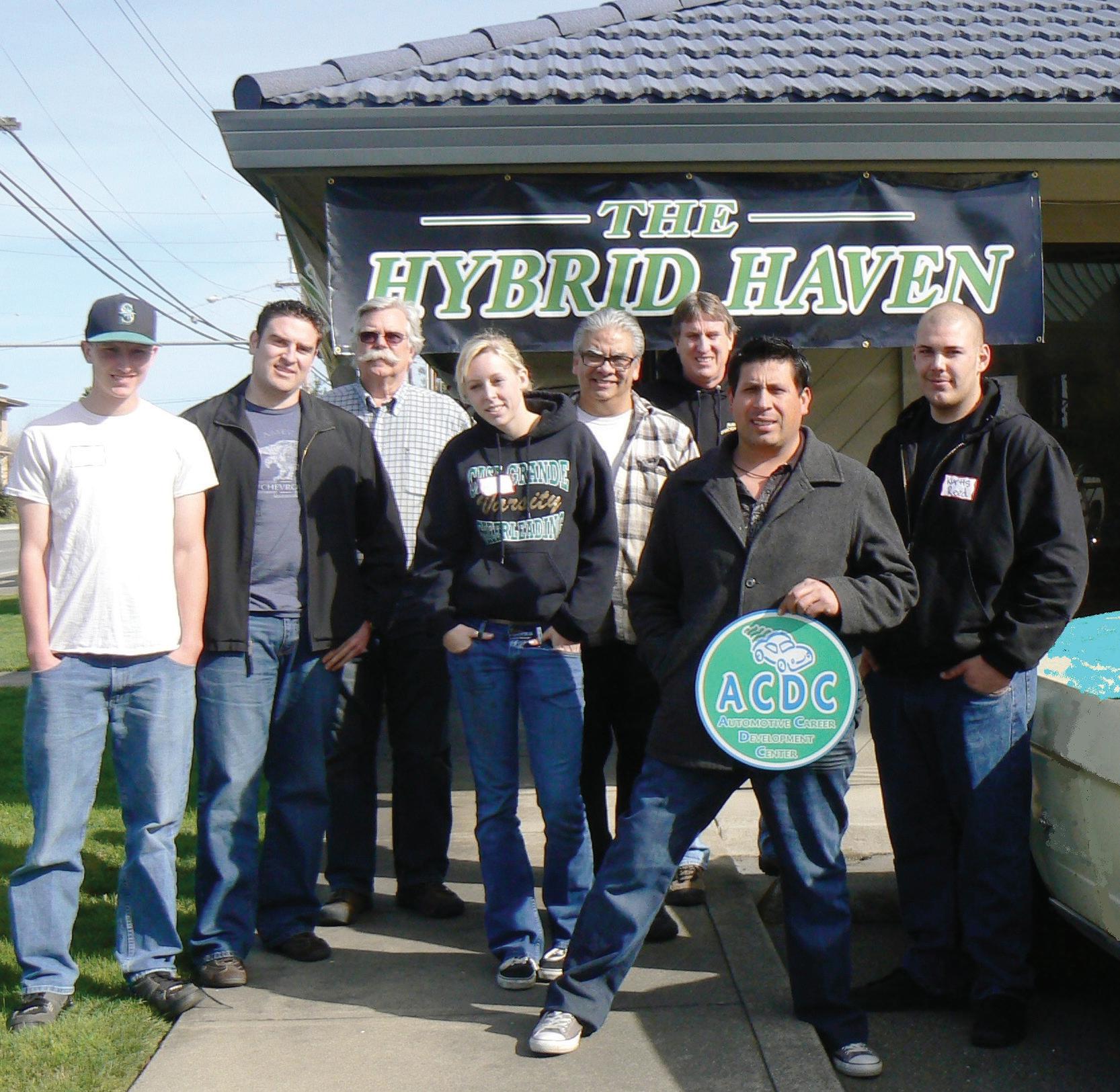
HYBRID HAVEN was a shop in California that had a great reputation. PHOTO BY CRAIG VAN BATENBURG
a part in this area, as steering can be done without a human behind the wheel.)
No. 4: Regenerative Braking Systems
These systems take over from just brakes. A modern automotive technician needs to understand many components in other areas, such as motors, inverters, and high-voltage battery systems, to grasp the totality of how an electric car slows down and comes to a complete stop. It’s more than calipers, disks, and master cylinders.
No. 5: Electrical/Electronic Systems
This area is broken into two parts. Electrical repair has been the weakest area in a typical American technician’s skill set. Understanding basic electrical theory, reading wiring diagrams, and testing using a digital volt-ohm meter has been the base-level training for too long. It may have worked to fix the easy stuff, but understanding waveforms using scopes, current ramping of coils, CAN systems of all types, and more requires additional training and specialized equipment. Additionally, high-voltage systems have dangerous potential, and the art of analyzing a modern electric vehicle becomes more than most of today’s repair and service people can handle. You will need additional training and the proper equipment.
No. 6: Advanced Power Electronics
This is where the inverter, DC-DC converter, on-board high-voltage battery charger, and grid charging end up. The previous area got you ready for more. Most of these components are replaced, not repaired. Understanding the construction and function of any part will lead you to better analyze that part of the system. Swapping parts can be easy, but you are not learning anything in the process.
No. 7: Thermal Management
The old HVAC (heating, ventilation, and air conditioning) name no longer applies. Cabin heaters have evolved from high-voltage resistive heaters and cool-
ant heaters (both sapping range from the EV) to high-voltage heat pumps. In a recent two-week class we call “Up Your Voltage,” a well-trained local technician said, “The drive system seems simple compared to the thermal system. Maybe you should spend more time teaching us about that.” I love constructive criticism, as it leads to improvements. He was right. When you only have a battery to power everything, wasting any of that energy is taking away from the range. For example, once you shut an EV off after a drive on a cold day, the high-voltage battery will often need to cool down. The heat can be redirected into the cabin. If you leave 30 minutes later, the cabin is still cozy. This is where moving the extra heat or cold can make sense, and that is being done today, hence the name “thermal management,” and there is a lot to manage.
No. 8 High-Voltage Battery Systems
This would be a new test. It’s included with ASE L3 now, but this article is about essential skills that you need today. The future is here and has been for quite some time. Learning about Li-ion cells, balancing circuits, parallel arrangements of cells (we call groups), series of cells in modules, replacement of failed parts contained in the pack, and so much more is a must. In the days of hybrids, entire packs were swapped out. Today, that is not practical and too expensive. Repairing packs makes sense if you know how. It’s the only part in an EV that must be fixed while high voltage is present. There is little training available to the aftermarket, but it can be and is being done successfully.
Now What
Is this the future of light-duty vehicles? I say yes. How did we clean up the tailpipe? We thought we had achieved a clean car, and then Carl Sagan noticed (as did many others) that carbon dioxide was trapping heat and the planet was warming. Oil was great for some things, but burning it was not one of them.
THREE OF these gases needed fixing.
PHOTO BY CRAIG VAN BATENBURG
THE HONDA Insights were the first modern hybrids sold in the USA.
PHOTO BY CRAIG VAN BATENBURG
THE LABEL every Honda motorcycle mechanic saw daily at work. PHOTO BY CRAIG VAN BATENBURG
I stopped at Ware Service Center LLC in Ware, Massachusetts, to talk about an xEV class for technicians that happens at ACDC, our training center. The owner, Joe Pocai, in his mid-60s, had no interest in the class about electric cars and said
flatly, “No.” We continued to discuss our careers. It was about the “motor head” times we grew up in. He was a General Motors-trained technician and worked at a Chevrolet dealership “way too long,” he said, as the flat-rate times went down
and his body got older. As I was leaving, he asked me why someone older than him was so passionate about electric vehicles. “I have never met a lifelong mechanic like you,” he said. I had heard that before. That led to a longer conversation.
I explained to Joe that it all came down to the Honda Company. In 1970, the EPA was created. Air pollution was horrible; the Cuyahoga River in Cleveland, Ohio, was catching on fire, Boston’s Charles River was so polluted you could not swim in it, and Los Angeles was the butt of late-night television jokes. It wasn’t funny. The environmental message was on the nightly news. It was also on every Honda motorcycle gas tank I saw daily at work. A label by the filler cap said “Preserve Nature — Always Wear a Helmet
Dayco Timing Belt in Oil
from Japan. The world was changing, and I went along for the ride, not blindly, as I loved to learn new things (still do). At the week-long Honda training in Cherry Hill, New Jersey, the first four hours on Monday morning were eventful. I met the other technicians, and they all looked like me: young, bearded, and loved Honda motorcycles. I did not know at the time, but Honda only allowed their cycle dealerships to take on the car franchise. None of us knew much about automobiles, nor did we have any formal training. We were ripe for anything new, and we loved high-revving, multi-valve, high-tech engines. Honda was king back then on the race tracks in Europe, and coming into their own here. The instructor was the son of a Honda manager back in California and had his hands full with the likes of us. As a surprise, he knew chemistry and the new EPA regulations. The pollu-
tion was CO, HC, and NOx — carbon monoxide, hydrocarbon, and nitrogen oxides. These were the byproducts of incomplete combustion at too high a temperature with a lack of enough oxygen. This all originated in the combustion chamber. What were Honda’s plans for the Civic? Fix the combustion chamber. Why not? That was the root cause. And how would a motorcycle company do that? With a Compound Vortex Controlled Combustion, or CVCC, engine.
I was asked by Motor Age to look at the “essential skills,” and the more I thought about it, what can you leave out? A technician has a “career,” not a “job.” They are not the same. 2025 was another year of learning, teaching, writing, and adding one more car to our growing fleet—a 2018 Honda Clarity PHEV. Another weird-looking Honda to add to the 2000 Insight HEV, which is even more strange. Science will
point us in the right direction as we learn more about our planet. My business model is supporting your future shop today. With that thought, there is always something to learn. It is never-ending. Essentials? That includes everything.
CRAIG VAN BATENBURG is the CEO of ACDC, a hybrid and plug-in training company based in Worcester, Massachusetts. ACDC has been offering high voltage classes since 2000, when the Honda Insight came to the U.S. When EVs were introduced in 2011, ACDC added them to their classes. Reach Craig via email at Craig@ fixhybrid.com or call him at (508) 826-4546. Find ACDC at www.fixhybrid.com.
Pressure Waveform Analysis:
The Art Following the Acquisition
A great pressure waveform can be a home run for engine mechanical diagnostics, but only if you know how to analyze the capture BY BRANDON STECKLER
DAILY,
I RECEIVE REQUESTS TO AID IN PRESSURE WAVEFORM ANALYSIS. It’s something I enjoy doing as it’s part of my way to give back to the industry that took such good care of me. Some believe it portrays mastery of the subject, but I’m not too much better than any of you, just a tad more experienced in this realm. Truthfully, it’s all just a matter of perspective. But I’ll share with you what gives me success in analysis. I’ll show you how I manipulate the in-cylinder compression waveform to the point where I can draw a diagnosis.
Scope Setup
I’ll be leveraging a PicoScope/pressure transducer because they’re the most widely
used tools in the automotive industry. However, you do not need a PicoScope or WPS500 (Pico pressure transducer) to perform the testing or the analysis. There are many capable tools on the market, and I own several of them.
The first thing I want to mention is the proper time base for engine mechanical pressure waveform analysis. Capitalize on the scope’s capability. A 20-second time base (or 2 seconds per division) is the best choice (Figure 1). This will give you enough time to capture all the information required.
Capturing this data with this much time on the screen will allow you to operate like a bird of prey. You hunt from several thousand feet in the air for a bird’s-eye view. We refer to that as a “trend view” (for obvious reasons). I prefer to see things occur over and over again. It’s easier to see faults when cycles repeat. We can zoom in for details later (caution: not every scope will let you
zoom in later. Some scopes will only let you zoom out).
Capture the data in raw format (meaning no filtering). Then, immediately save the captured file to a safe and accessible place; I recommend the cloud (Figure 2). If I don’t save right away, I tend to forget, or if I filter first, I may inadvertently filter out some desirable information and ruin the capture’s ability to yield a diagnosis.
Preparing for Analysis
Part of proper analysis is setting yourself up for success. Too many times, I’m asked to analyze a still screen capture. Most of the time, the picture I’m offered isn’t focused properly, leaving diagnosis off the table. It’s simply a ruined opportunity. Regardless of how good a diagnostician you may be, if you cannot see the data, you cannot draw an accurate conclusion. You must first prepare to analyze.
Begin by zooming into your trend view
FIGURE 2
FIGURE 1
FIGURE 3
(from above) to the point where one cycle fills the screen. We refer to this now as a “detailed view.” Select the rulers from the toolbar and apply phase rulers (Figure 3). This will then allow you to partition the in-cylinder waveform four ways (to represent the four strokes of a complete engine cycle).
Zoom in once again to fill the screen with only what you desire to see. In this case, I am interested in a few characteristics that I will view:
• Timing of the exhaust valve opening (EVO)
• Timing of the intake valve opening (IVO)
• Timing of the intake valve closing (IVC)
• The duration of the intake valve
• The negative pressure created in the cylinder during the induction stroke
The characteristics, or points of interest, are of the utmost importance for engine mechanical and breathability diagnostics. But to view those characteristics, I’ll have to manipulate the capture for clarification; this involves a bit of filtering. Filtering is a double-edged sword. It will allow you to clean up a capture, but it can also degrade one. Only filter as much as required.
The two types of filtering I use are resolution enhancement and low-pass filtering. It’s important you know the difference between the two. Active filtering allows me to select a low-pass filter threshold of my choice. In this example, a 1-kilohertz lowpass filter was selected. What that means is any portion of the signal that toggles faster than a rate of 1,000 times per second is removed from the waveform. It’s like taking an eraser and removing the hairiness from the waveform (Figure 5).
The other type is vertical resolution enhancement. This type of filtering creates a similar effect to the pressure waveform but goes about it in a different fashion (Figure 6). If you can imagine an 8-bit scope screen broken up vertically into about 4,100 discrete points. These points are opportunities to place a “dot” (as in connect the dots). Well, the way a scope plots data is by looking at the dot as a threshold. If the value measured by the scope exceeds the dot, it must place the dot at the next vertical opportunity. With that, waveforms can tend to look fuzzy. Now, increasing the vertical resolution to 16-bit offers the scope over 65,500 discrete points. If the threshold for a dot is exceeded, the next dot is not much further away, reducing or eliminating the hairiness altogether (Figure 7).
Leveraging Measuring Cursors
If you weren’t aware, a diagnostician is only as precise as the tooling he or she leverages. With that, capitalize on what your precision measuring devices have to offer. Powerful digital storage oscilloscopes will have a pair of vertical cursors (for measuring a point in time and/or elapsed time between the two of them). They will also have a pair of horizontal cursors (to measure the value
of a signal in its selected unit of measure, or the difference between the two of them).
I leverage the vertical cursors to indicate when valves open or close. Using the pair of them, one can easily determine the duration of an event. This is a great way to reveal a worn cam lobe or even a collapsed lifter, as displayed here (Figure 8).
The horizontal cursors are great for indicating when a cylinder isn’t breathing properly. Whether it’s a labored inhalation or exhalation, the cursor will make light work of it. As we can see in this example, during the third quadrant of the capture (the induction stroke), as the piston descends in the cylinder bore, rather than displacing air and filling the void in the expanding combustion chamber, the cylinder is drawn into a negative pressure, or what we mechanics like to refer to as vacuum. The pair of horizontal cursors
FIGURE 4
FIGURE 5
FIGURE 6
FIGURE 7
indicates that the piston simply can’t move air into the cylinder (Figure 9).
Data Storage for Later Review
As mentioned in many previous articles, a good diagnostician is always looking to improve or understand at a deeper level. It’s for this reason that I highly recommend taking the time to save your captured data properly and thoroughly. You simply can’t count on your memory to serve you correctly after troubleshooting thousands of cars each year. You need to take the time to be sure all pertinent information is included in your file for review at a later date.
So, how can we ensure we have everything we need in the document? Well, if you can send it to another technician on the other side of the world, and he or she can determine what is wrong in the capture (by way of the story the data tells and by the notes attached to the capture), you have done your job sufficiently. Here is the information I like to include in the file:
• Engine configuration: 5.3L V8, N/A, with active fuel management
• Scope channel: A = Relative compression, B = Intake pressure, C = Ignition, D = In-cyl)
• Conditions: “Good,” “Bad,” or “Unknown”
• Notes: Found damaged No. 8 intake valve lifter
The information above, for the example vehicle, allowed me to analyze the data accurately without the vehicle in my presence or the diagnostic technician available. He did a fantastic job labeling his captures, which allowed me to do my job as an analyst (Figure 10).
There is an equally important aspect of saving data, and that has everything to do with where you place that data. When I began my adventure of a deep dive into
diagnostics, I found myself saving very valuable data in the most random locations. I was more like an unruly teenager than I was a professional diagnostician. I had data irresponsibly stored anywhere within one of four USB thumb drives, a hard drive, on
the desktop of at least three PCs, and on a couple of SD cards. It sometimes took hours to find what I was looking for. I’d spend the time searching through hundreds of improperly labeled captures on one media device before switching to another device
The BendPak 12AP-SRT short-rise two-post lift cost-effectively improves tire shop productivity and efficiency while mitigating risk. With 12,000 pounds rated capacity, massive wingspan that reaches most OEM lifting points, and BI-METRIC™ arms to suit virtually every vehicle lifting requirement – symmetric or asymmetric. The 12AP-SRT can raise 99 percent of cars, SUVs, and trucks to a comfortable working height much faster (and easier) than a set of jacks. Its single-point safety lock system, super-strong automatic arm restraints, and limited max lifting height of 47 inches deliver superior peace of mind. The short 93.5inch columns offer lower product, installation, and maintenance costs, plus a cleaner floorplan. Check out the full line of BendPak lifts at bendpak.com or call us at 1-800-253-2363
to continue the process. Needless to say, I’ve learned my lesson the hard way. There is a much better way to store data. My recommendation is to place the data in the cloud.
Begin by opening a folder on the desktop of your PC. Label the folder by way of the vehicle. I typically name the folder the appropriate year/make/model/symptom. In that folder I place captured data from graphed scan data, video files, lab scope files, thermal imager files, etc. If you’ll notice, the common word used is “files.” It’s important to save files so you can interact with them. The ability to manipulate the data to display what you desire to see is of the utmost importance. Don’t misunderstand, it’s fine to save screenshots or pictures, but always include the file from which those pictures were derived. Screenshots can always be captured from a stored file after the fact.
Remember, my filing system may differ in structure from yours as I provide technical support to diagnosticians across the globe. For instance, I have data for my business stored on one of three different cloud-based storage facilities (Google Drive, Microsoft OneDrive, Dropbox). Don’t ask why, it’s just the way it’s always been for me. However, I only store automotive-based data in the same facility.
I have one main folder labeled “Automotive Diagnostic Support” and a series of subfolders that follow in a logical system. It is as follows:
OneDrive > Automotive Diagnostic Support > Client Name > Subject Vehicle
All the data from that particular vehicle gets stored in that same folder structure. In this fashion, nothing gets lost, and it’s very easy to locate, even years later. I store information on the cloud because when my PC crashes, or if I don’t have access to it at the moment, the information will still be accessible, regardless of where I am in the world. As long as I have an internet connection.
Proving the Process Works
In the grand scheme of things, we do whatever it is we do (as diagnosticians) to solve
the issues causing the symptoms our clients are experiencing. Hopefully, we are getting to the root cause of the symptom and not simply fixing the symptom itself.
Regardless, our processes exist for a reason, but if one were to break down my information- and analysis-based diagnoses, you’d realize that all of the information I base my diagnostic decisions on is bits of the story to be told. And when I have the pieces of the story fitted together (like puzzle pieces), I almost always have a conclusive diagnosis that aligns with them.
Our diagnostic data should tell that story. That is how you know you have captured the right data. Let’s walk through the entire story of this poor Chevy truck as the data suggests.
Although the data was not visible in the captures demonstrated earlier, a four-trace lab scope capture demonstrated the following:
The data in those captures suggested that one of the eight cylinders was not performing like the other; the suspect cylinder (correlated with the ignition sync) was determined to be cylinder No. 8. The in-cylinder compression waveform illustrated the cylinder’s inability to inhale, and the vacuum trace confirms not only that a duration issue with the No. 8 intake valve
lifter exists, but also that the issue is in fact a collapsed lifter (and not a worn cam lobe).
The late occurrence of the suspect cylinder’s vacuum transfer points shows the shift in time. However, they are still very crisp and abrupt. The same characteristics can be seen in the in-cylinder waveform. A worn cam lobe would show the same shift in time, but there would tend to be less of an abrupt transfer point as metal displacement from the cam lobe would hinder its opening smoothly (Figure 11).
So, as you can see, it’s certainly not magic but an ability to understand and analyze the data you have captured. If you don’t capture and/or save the data properly, you have no data to manipulate to show you what you need to make a diagnostic decision. And, without that, you simply can’t be as precise as is required (not without extensive disassembly and evaluation).
Also, take the time to understand how things work. Take the time to understand how to leverage the tools that show you the story to be told. Take the time to capture and save data properly because the consequence of not doing so would lead to regret and many hours of repeated tests. Finally, capitalize on your tools’ features and capabilities to ease and streamline this process for you. There’s definitely a reason certain tools require a larger investment of money. The takeaway is that it is an investment. And leveraging the tools as I have described above will help you realize that return on investment a heck of a lot sooner.
FIGURE
In this business, timing is everything. Since 1945, we’ve been your family-owned source for OE parts, training, and creative business solutions. Get in touch to discover how we can customize a program that keeps your business firing on all cylinders.
AUTOMOTIVE PRODUCT GUIDE
Coverage for more than 100 vehicle systems
The MT2600 from Snap-on is a versatile diagnostic tool that provides intuitive access to diagnostic capabilities and OEM-specific coverage for 50 domestic, Asian, and European makes back to 1983. This tool provides coverage for more than 100 vehicle systems and includes technologies such as TPMS, hybrid power, collision avoidance, and steering and angle sensors, plus extensive capabilities like code scanning, live data graphing, functional tests, relearns, and adaptations. It comes standard with both English and Spanish language capabilities. Using the Snap-on Security Link, the MT2600 allows technicians to work on vehicles with secure gateways from major OEMs. Users can update the software for their MT2600 online with over-the-air updates.
Designed for maximum organization
The 4-Drawer Tool Cart Set from SK Tools comes stocked with the company’s latest socket sets, precision-engineered screwdriver sets, and durable dual-material handle pliers sets. This tool cart is designed for maximum organization and efficiency and includes exclusive SK swag. This fully-loaded cart is also available as a 6-drawer option.
Eliminates the physical strain of wheel service
The BendPak RWS-200WL Battery-Powered Wheel Lift eliminates the physical strain of wheel service, protecting technicians while delivering greater uptime. Unlike air-powered models that must stay tethered to an air supply, this rechargeable battery-powered lift is truly mobile for use throughout the shop. With double the power of 12V units, the RWS-200WL delivers faster lift speeds, superior torque, and a 200-lb capacity to easily handle oversized wheels and tires. By reducing technician fatigue and lowering the risk of strain-related injuries, the RWS-200WL can help reduce workers’ comp claims, support OSHA-compliant safety practices, and even contribute to lower insurance premiums over time.
Features magnetic socket extension holder
The Carlyle Tools Magnetic Tool Tray features a magnetic socket extension holder with a non-marring design to protect surfaces while keeping sockets organized and within reach. Its low-profile, flexible construction bends easily to fit in tight spots or curls up for compact storage. Designed to magnetically cling to toolboxes, lifts, and even curved or ferrous surfaces. Available in a 4” or 10” option.
Features a 5” display
The ArtiDiag HD from TOPDON features full system diagnostics that are designed to offer comprehensive insights by reading and clearing codes across all major systems, including engine, transmission, and ABS, among others. It features advanced calibration capabilities, injector coding, idle speed adjustment, clutch matching, and speed limit for 60 medium- and heavy-duty truck brands worldwide. The ArtiDiag HD also allows users to analyze vehicle performance with real-time sensor data and capture freeze frame information for precise fault diagnosis. Additional features include a 5” display, a 3V/3,150mAh battery, a 1.6 GHz CPU Quad-Core, and 2G RAM.
WalkAway inflation system releases inflation chuck
The Hunter Engineering Road Force WalkAway Wheel Balancer is capable of reducing door-to-door four-tire changeover times by up to 45%. The key component for the timesaving is the WalkAway inflation system, which automatically releases the inflation chuck when inflation is compelete. This allows the machine to perform the balance spin, greatly reducing the time spent inflating assemblies on the tire changer. Additional features include a new two-piece hood that enables the balancer to sit 4.5” closer to the wall, a new hood angle sensor to provide a smooth opening, and updated software.
AUTOMOTIVE PRODUCT GUIDE
Offers over 95% vehicle coverage
Bosch debuted its newest TPMS sensor configuration tool at AAPEX and SEMA 2025. The TPA 400 is designed for configuring universal TPMS and Bosch QUICK FIT+ sensors. Powered by an integrated OBD module and over-the-air software updates, this tool is compatible with 20 universal sensor brands, including Bluetooth sensors, and boasts vehicle coverage of over 95%. Technicians are supported by step-by-step instructions for sensor programming and vehicle relearn procedures, accessible via a 2.8” color display.
Includes 1/4”, 3/8”, wand 1/2” ratchets
The Sonic Tools NEXT Ratchet Set is a 15-piece collection designed for precision and reliability. The set includes three ratchets, 1,4”, 3/8”, and 1/2”. The set is designed with an ergonomic, thermo-plastic grip that ensures optimal hand contact, resulting in greater comfort and enhanced power transmission of up to 558.3 ft-lbs. Each ratchet features a 60-tooth mechanism that delivers smooth operation, rugged performance, and minimal back drag. All ratchets include sealed heads that protect internal components from dirt and debris, extending their lifespan. Backed by the company’s lifetime warranty.
Permanently installed with direct lines to waste tank
The JohnDow Industries Centralized Fluid Evacuation System is built directly into the service facility, designed to provide a cleaner and safer work environment, faster service turnaround, and higher customer satistfaction. This system is permanently installed with direct lines to the waste-oil tank and requires no compressor which means reduced noise, wear, and maintenance. This system is designed for high-volume, multi-bay operations.
From micronized carnauba to the latest graphene and ceramic formulas, our full spectrum of BRIGHTLINE professional car appearance products has everything you need to make your customers’ cars – and your business – shine. So whether you run an automatic, self-serve or hand-wash and detail operation, make the smart choice with BRIGHTLINE.
TECHNICAL SERVICE BULLETINS
Dodge
DURANGO
This bulletin applies to 2021-2025 Dodge Durango vehicles built on or after Feb. 1, 2021, and on or before Nov. 24, 2024, equipped with a 3.6L V6 VVT engine. An extended crank condition may exist. The likely cause is the fuel pressure regulation.
Perform a fuel pressure and fuel system leak-down test. If not within spec, replace the fuel pump module with P/N 68535771AB.
This bulletin applies to certain 20222024 Ford E-Transit vehicles built in the
Kansas City plant from Sept. 1, 2021, through June 24, 2024. Over time, the electric vacuum pump may stop working due to broken internal wires. This may result in a hard brake pedal and perceived reduction in brake response. If the EVP fails, DTC P050F will set, the brake warning lamp will illuminate, and a Check Brake System message will appear, accompanied by an audible chime. Replace the EVP with P/N NK4Z2A451-D under warranty.
This bulletin applies to 2022-2025 Cadillac Escalade and Escalade ESV vehicles. The ABS MIL, SES MIL, Service Brake System warning, and Service StabiliTrak messages may appear. A change in brake pedal effort may also be experienced. DTC P0606 and P0562 may be set in the BSCM.
This condition is due to a low-voltage condition. This may be more
prevalent in colder ambient temperatures and a lower battery state of charge. Test the battery using the GR8/DCBS and replace, if needed. Testing the battery at the ambient temperature where the issue occurs could help identify any battery-related issues. Inspect the battery, battery cables, engine harness junction/fuse block (X50A), and battery fuse block X50B connections for tightness and cleanliness.
If applicable, perform PIT6260
Dead battery/Excessive Battery Draw Drain Parasitic/Low Battery Voltage and reprogram the BCM. Also, inspect for any type of aftermarket equipment that could draw down the battery (dash cameras, cell phone chargers, etc.). Inspect for any parasitic draws.
THERE’S THE RUB
This bulletin applies to 2022-2023 Chevy Blazer AWD and Traverse AWD
Photo: Ford
Cadillac
CADDY LOW BAT
CRANKY
Photo: Dodge (Courtesy Chrysler)
Ford
E-TRANSIT ALERT
INFORMATION COURTESY OF MITCHELL 1
Photo: Cadillac
Chevy
vehicles. A ratcheting type noise may be heard when disengaging the AWD. The condition may be caused by the inner differential carrier output shaft contacting the driveline torque tube’s casting line. Replace the torque tube. For Blazer, use P/N 85660253. For Traverse, use P/N 85592566.
Chevy
This bulletin applies to 2021-2025 Jeep Wrangler and Gladiator vehicles built on or after Jan. 1, 2021, equipped with a 3-piece hard top. A water leak may exist from the top of the B-pillar when the vehicle is parked on a downward incline.
Perform a B-pillar water leak test. Raise the vehicle rear about 12 inches from the ground. Soak the entire roof area with water. Inspect both cabin B-pillars. If a leak is found, lower the vehicle and remove both Freedom panels and place them on a padded work surface. Ensure that the Freedom panels are dry and install the foam pads at the rear outer corner of both left and right Freedom panels.
Foam, B pillar rear, right ...
68443146AA
Foam, B pillar rear, left ...
68443147AA
Firmly press the foam pads on both panels to promote full adhesion. Verify that the interior is fully dry. Install the panels.
Photo: Mitchell1
Porsche
PORSCHE BREATHER
This bulletin applies to 2019 Porsche Cayenne and 2017 Panamera vehicles, equipped with a V8 biturbo engine. Issues may involve a rough-running
engine, a whistling noise, and/or a check engine light on. It’s found that the diaphragm in the oil breather line (crankcase vent tube) or the tube itself from either bank 1 or 2 can be cracked, causing this failure.
• Any of the following DTCs may be stored:
• P227900 (leak behind throttle valve, bank 1)
• P0300(X)00 (random/multiple cylinder misfire)
• P162400 (engine control indicator light switched on)
• B19A8F0 (display of reduced engine output, active)
• B19CAF0 (display of start/stop failure. Active)
• B19ACF0 (display of fault in engine controller, active)
Replace only the breather lines. If the fault code(s) remain after a test drive, check the oil air separator for damage.