

Benefits:
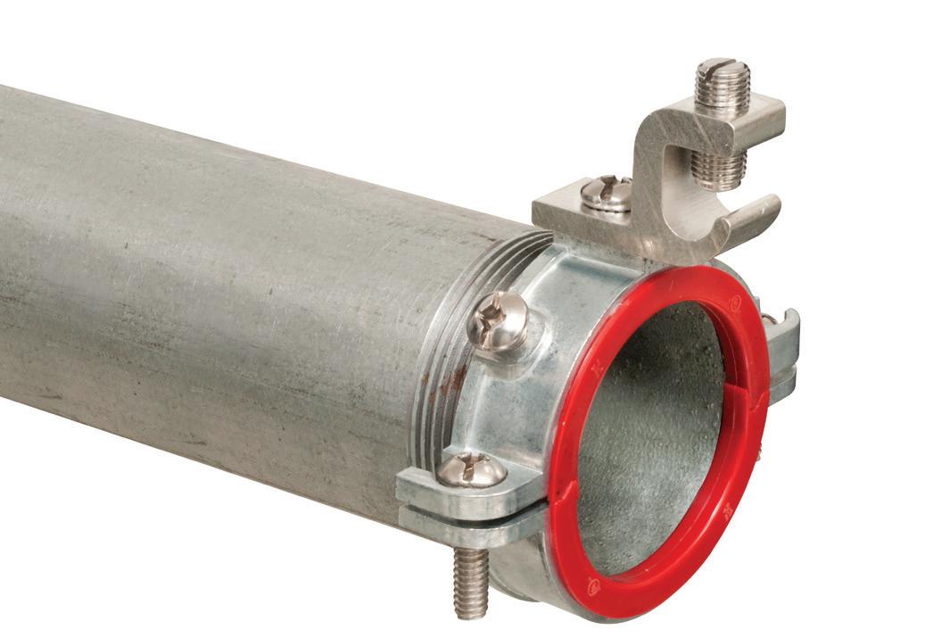
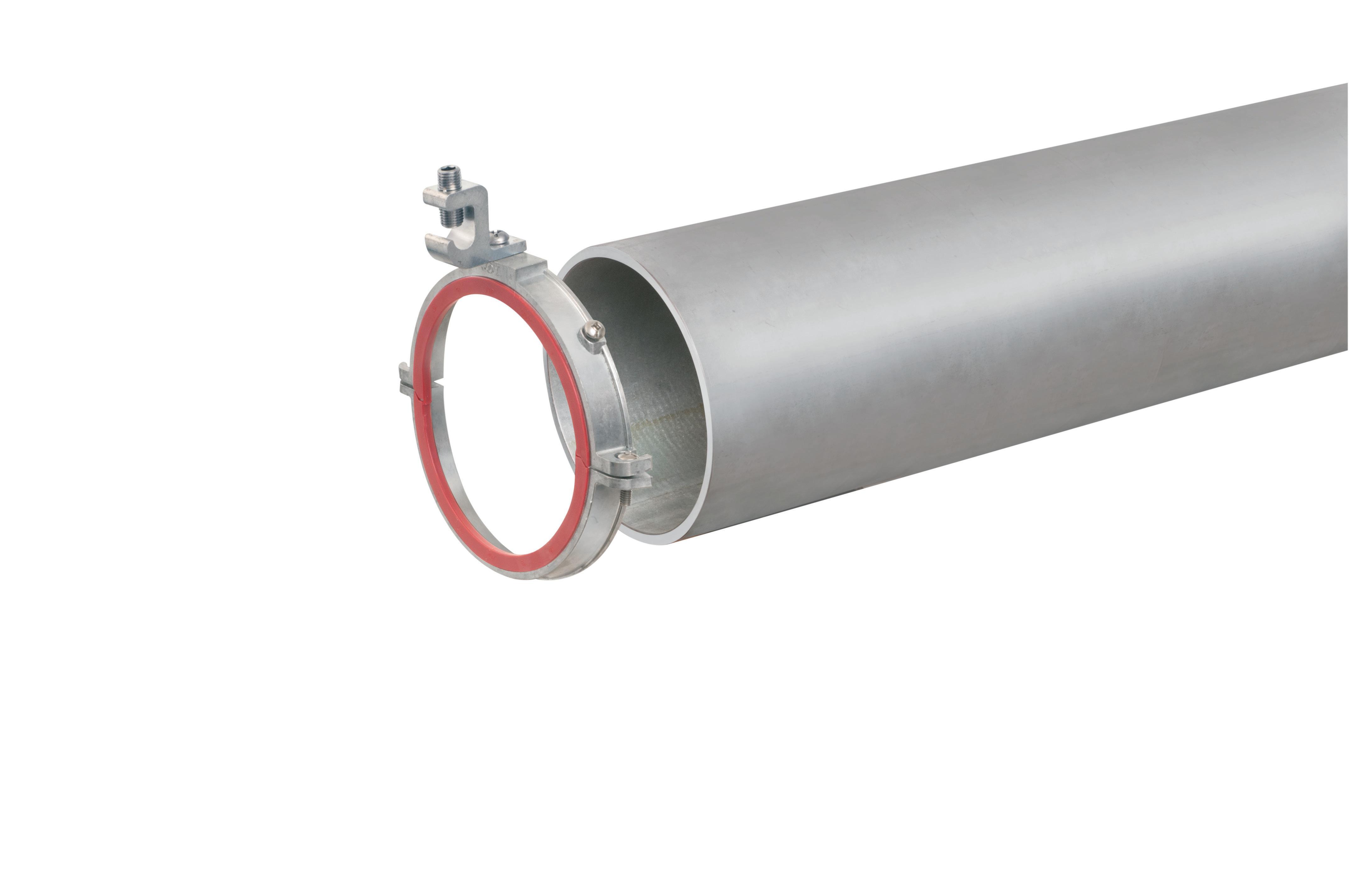
ꞏ Features a patented, low-profile design with an ergonomic tightening mechanism & O-ring seal
ꞏ Listed to UL 651 & UL 50E
ꞏ Conforms to NEMA TC 3


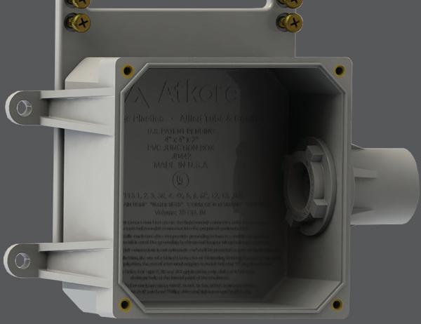


Versatile Tightening Mechanism Maximizes Internal Junction Box Space O-ring


Completely Nonmetallic


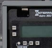
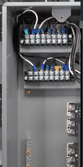
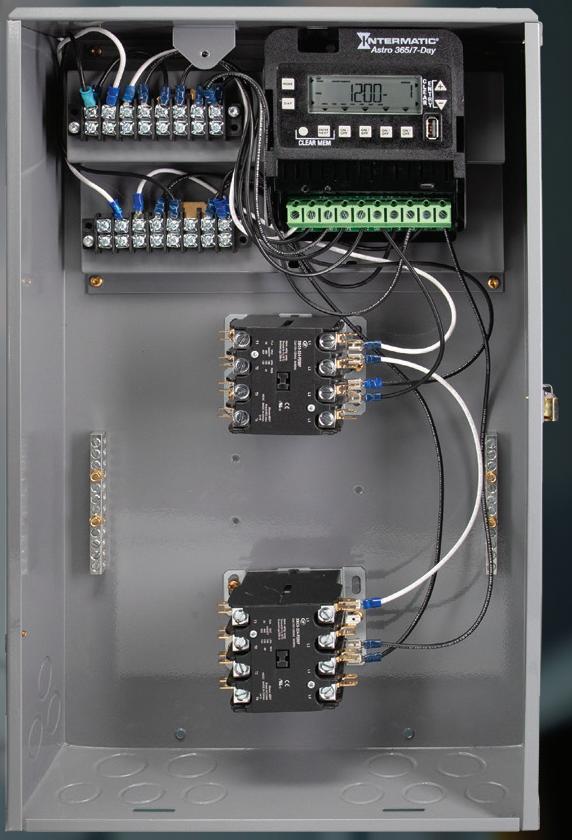


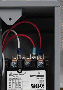


Need a control that can handle more? Simplify projects without sacrificing performance with one of four new Contractor Boxes from Intermatic. Our expanded portfolio of field-ready solutions allows contractors to install a durable enclosure that houses a built-in 7-day Astronomic timer and a 3-pole, 4-pole, 8-pole, or 12-pole contactor.
These versatile, UL-listed solutions save time in the field and can support applications ranging from motor control and parking lot lighting to big box stores and university campuses. Upgrade today and install our code-compliant alternative to a la carte lighting control boxes and stackable contactors.
From no power to intermittent faults and hidden power quality culprits, learn how to quickly identify and fix the three most common causes of branchcircuit failures.

From scheduled shutdowns to emergency repairs, understanding the distinct risks of planned vs. unplanned maintenance is key to safe execution.

Field-tested ways electrical contractors can improve efficiency and increase profit margins.

From early mornings to late-night service calls, this snapshot of residential electricians reveals the skills, tools, and training behind one of construction’s most essential — and often overlooked — professions.



With its exclusive online content, ecmweb.com is a valuable source of industry insight for electrical professionals. Here’s a sample of what you can find on our site right now:

ASSESSING THE IMPACT OF CUTTING ELECTRIC VEHICLE
Electric Vehicles Incentives for purchasing EVs and installing chargers are on the way out, sending out ripples of concern for beneficiaries. ecmweb.com/55305373
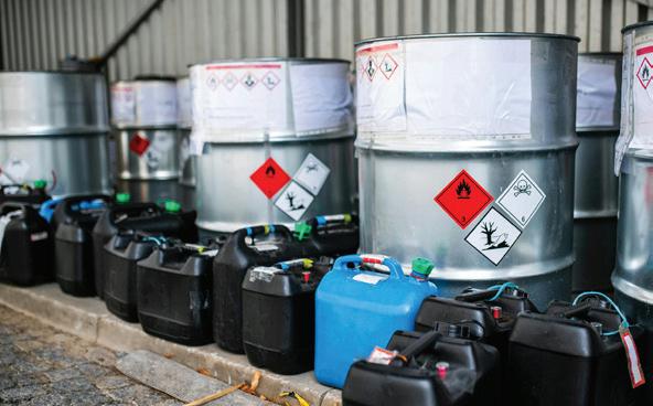
TIPS FOR SAFELY HANDLING FUEL
Safety How to mitigate the risk of smoke/fume inhalation and fires when using fuel on job sites ecmweb.com/55305630

Quiz It’s time to test your knowledge on transformers! ecmweb.com/55303314
Editorial
Editor-in-Chief: Ellen Parson, eparson@endeavorb2b.com
Managing Editor: Ellie Coggins, ecoggins@endeavorb2b.com
Editor: Michael Morris, mmorris@endeavorb2b.com
Art Director: David Eckhart, deckhart@endeavorb2b.com
Consultants and Contributors
NEC Consultant: Mike Holt, mike@mikeholt.com
NEC Consultant: Russ LeBlanc, russ@russleblanc.net
Sales and Marketing
VP/Market Leader - Buildings & Construction: Mike Hellmann, mhellmann@endeavorb2b.com
Regional/Territory Account Manager: David Sevin, dsevin@endeavorb2b.com
Regional/Territory Account Manager: Jay Thompson, jthompson@endeavorb2b.com
Regional/Territory Key Account Manager: Ellyn Fishman, efishman@endeavorb2b.com
Media Account Executive – Classifieds/Inside Sales: Steve Suarez, ssuarez@endeavorb2b.com
Production and Circulation
Production Manager: Josh Troutman, jtroutman@endeavorb2b.com
Ad Services Manager: Deanna O’Byrne, dobyrne@endeavorb2b.com
User Marketing Manager: James Marinaccio, jmarinaccio@endeavorb2b.com
CEO: Chris Ferrell
CDO: Jacquie Niemiec
COO: Patrick Rains CRO: Paul Andrews
CMO: Amanda Landsaw CALO: Tracy Kane
EVP Building & Construction Group: Chris Perrino
VP of Content Strategy: Mike Eby
Electrical Construction & Maintenance (USPS Permit 499-790, ISSN 1082-295X print, ISSN 2771-6384 online) is published monthly by Endeavor Business Media, LLC. 201 N. Main St 5th Floor, Fort Atkinson, WI 53538. Periodicals postage paid at Fort Atkinson, WI, and additional mailing offices. POSTMASTER: Send address changes to Electrical Construction & Maintenance, PO Box 3257, Northbrook, IL 60065-3257. SUBSCRIPTIONS: Publisher reserves the right to reject non-qualified subscriptions. Subscription prices: U.S. ($68.75 year); Canada/Mexico ($ 112.50); All other countries ($162.50). All subscriptions are payable in U.S. funds. Send subscription inquiries to Electrical Construction & Maintenance, PO Box 3257, Northbrook, IL 60065-3257. Customer service can be reached toll-free at 877-382-9187 or at electricalconstmaint@omeda.com for magazine subscription assistance or questions.
Printed in the USA. Copyright 2025 Endeavor Business Media, LLC. All rights reserved. No part of this publication may be reproduced or transmitted in any form or by any means, electronic or mechanical, including photocopies, recordings, or any information storage or retrieval system without permission from the publisher. Endeavor Business Media, LLC does not assume and hereby disclaims any liability to any person or company for any loss or damage caused by errors or omissions in the material herein, regardless of whether such errors result from negligence, accident, or any other cause whatsoever. The views and opinions in the articles herein are not to be taken as official expressions of the publishers, unless so stated. The publishers do not warrant either expressly or by implication, the factual accuracy of the articles herein, nor do they so warrant any views or opinions by the authors of said articles.
Reprints: Contact reprints@endeavorb2b.com to purchase custom reprints or e-prints of articles appearing in this publication.
Photocopies: Authorization to photocopy articles for internal corporate, personal, or instructional use may be obtained from the Copyright Clearance Center (CCC) at (978) 750-8400. Obtain further information at www.copyright.com.
Archives and Microform: This magazine is available for research and retrieval of selected archived articles from leading electronic databases and online search services, including Factiva, LexisNexis, and ProQuest.
Privacy Policy: Your privacy is a priority to us. For a detailed policy statement about privacy and information dissemination practices related to Endeavor Business Media products, please visit our website at www.endeavorbusinessmedia.com.
Please Note: The designations “National Electrical Code,” “NE Code,” and “NEC” refer to the National Electrical Code®, which is a registered trademark of the National Fire Protection Association.
Corporate Office: Endeavor Business Media, LLC, 30 Burton Hills Blvd., Ste 185, Nashville, TN 37215 USA, www.endeavorbusinessmedia.com


Assemble Conduit Above TrenchNo Workers BelowPrevents Injuries and Deaths. Also Allows Digging a Narrower Trench for Less: Excavation, Concrete, Slurry, Backfill & Shoring.









By Ellen Parson, Editor-in-Chief

Amid the national skilled labor shortage that continues to hinder industry growth, I’m proud to share that EC&M’s “The Everyday Electrician” has officially gone viral — and the timing couldn’t be better. When we surveyed top electrical design and electrical contracting firms for our annual Top 40 and Top 50 surveys this year, more than 60% of respondents indicated that “difficulty finding and retaining quality employees” was the greatest threat to their business. Yet, even in the face of these hiring challenges, a new wave of young professionals is stepping up to lead — and The Everyday Electrician is helping to amplify their voices.
If you’re not familiar with this short-form video series, now’s the perfect time to dive in (www.ecmweb.com/members-only/videos/the-everyday-electrician). Since launching this concept in January 2024, these reels have quickly gained momentum across our social platforms (Instagram, YouTube, and TikTok), really taking on a life of their own and quickly becoming a favorite among our audience. At the heart of the series is Trevor Ottmann, president of 3/0 Electric, based in Bennet, Neb., who brings viewers along with him on real-life job-site adventures (mainly in the agricultural and industrial markets). His videos offer an authentic, behind-the-scenes look at the electrical trade, featuring troubleshooting techniques/hacks, practical tips/best practices, routine challenges, and clever job-site strategies — all delivered in a straightforward, relatable way that resonates with electricians at every level. One of Trevor’s recent reels, in which he explains why roto-phase installations can be so intimidating, recently went viral on Instagram, garnering more than 127,000 views, 1,900 likes, 850 shares, and 120 comments (and still climbing). Watch the clip at bit.ly/3Uj5mrW to see what all the buzz is about — in just a couple of weeks, this video truly proved to be electric.
At a time when the labor gap is only expected to widen, we need more voices like Trevor’s to demonstrate the practical and technical side of electrical work. The breakout success of The Everyday Electrician is proof of what happens when we elevate real people doing real work in the field — the entire industry benefits. Now it’s time to keep that momentum going, and where better to do that than the 2025 NECA Show. Presented by the National Electrical Contractors Association and held September 13-15 in Chicago, this event is the perfect place to network. EC&M’s editorial team and Trevor, our very own everyday electrician, will be in attendance, making the rounds to see what’s new with the latest new products and technologies, attend educational sessions and panel discussions, and network with attendees. Make sure and stop by EC&M’s Booth #3726 to not only meet Trevor in person and register for a chance to win cool Everyday Electrician merchandise (T-shirts and hats) but also to talk with our editorial team about what issues and topics are most important to you as an electrical professional.
If you’re interested in showcasing your electrical expertise in this type of format, we want to talk to you. Stop by the booth and see us at NECA! We’re on the hunt for more electricians from all types of market segments to join Trevor as one of EC&M’s electrical influencers. And if you can’t make this year’s NECA, consider submitting a short video (2 minutes or less, vertical format) at ecmweb.com/55278724 for consideration. Although this may be our first reel to go viral, the performance of all of Trevor’s video content is growing rapidly, routinely generating thousands of views per reel and significant engagement/interaction. That tells me this is more than just a moment — it’s a signal that the next generation of electricians is ready to lead. With your help, The Everyday Electrician will continue to elevate the trades, educate our workforce, and inspire future generations of electrical professionals.


By Sydney Parvin and Phil Nimmo, MCA, Inc.
You’ve handed over the job from estimating to the field, so the field is off and running. But how do you know that you’re on the right track and the job is proceeding as intended? Most contractors have realized the importance of maintaining regular communication between the field and office, and this goes beyond the foreman/project manager walking a job and checking if they’re okay. We all want technology to replace personal interaction, but the most effective job review meetings still include data-driven discussions with information collected and categorized over time.
Job review meetings are set up to ensure “the office” knows where the job stands and that the field has timely access to the resources/support that they need. A standing weekly job review meeting between a project manager and foreman is a great start — however, that alone doesn’t ensure that the needed support is going to be available. For problem resolution and project success, the review must include all the stakeholders that have access to resources and solutions.
A job review meeting is like any other meeting; you get out of it what you plan and prepare for. Following the steps below will help ensure your team has effective communication during the job. Getting what you need in every step — and engaging different people as necessary — is called Channels to Action™.
Know your objective for the meeting, and have an agenda in place to meet that objective. Job review meetings are about establishing and maintaining project control. To do this, you need to:

• Know where the job stands today.
• Know where the job should be.
• Establish a plan to cover any gaps between the two.
The agenda presented in Fig. 1 on page 12 is a tested and proven agenda for facilitating data-driven, outcomefocused discussions.
Make sure the right people attend the meeting. This should consist of (at the very least) the project team representatives and the functional leaders needed to ensure labor, money, material, and tools are available. The regular participants should include the project manager, foreman, and project coordinator. Depending on the relevant issues pertaining to the job, other participants can include executive management, senior project managers, superintendents, vendors, prefab coordinators, or
safety directors as needed, depending on the issues and if the smaller team has been unable to resolve the situations.
Using quality data ensures the time during the meeting is spent on the issues that matter most. Data is right when opinions fail. Data can resolve all the arguments and disagreements that opinions introduce. Experience plays a significant role in planning and execution, but analysis is where data excels.
Before the meeting, make sure the data lines up with the reality of the job, as bad data coming into the meeting is not useful. To do this, review the data for any outliers or misnomers. Check for potential errors that can occur in the four stages of data quality, shown in Fig. 2 on page 12. According to Dr. Perry Daneshgari and Dr. Heather Moore’s report, “Agile Construction for


the Electrical Contractor Second Edition,” the four stages of data quality are collection, reporting, recording, and output. Prior to the meeting, note any potential data quality issues, and, if possible, address them prior to the call with the person who knows the reality of the job best — the foreman.
Going back to our meeting objectives and the agenda shown in Fig. 1, knowing where we are and where we should be — and having a plan to close the gap between the two — is our goal for the job review meeting. To achieve this objective, we need to have a reference point for the overall job and a reference point for the day-to-day work.
Reviewing the common obstacles that occur day to day on the job is critical because these silently eat away at the available hours to complete the work. Even though scheduled work is impacted nearly daily across most construction jobs, the issues encountered by field personnel are more often than not left unspoken, according to Dr. Heather Moore’s PhD dissertation on “Exploring Information Generation and Propagation from the Point of Installation on Construction Jobsites: An SNA/ ABM Hybrid Approach.”
ASTM Standard E2691 suggested tools like Short Interval Scheduling (SIS®) allow the field to establish a reference point for what they need to accomplish and report the daily obstacles that get in the way of doing that, as required by the 2022 Annual Book of ASTM Standards. Categorizing data is key, so you can refer to it and work on what’s impacting you the most. The example in Fig. 3 on page 14 shows the obstacles reported on the electrical work for a remodel of a multi-story office building.
Knowing where you are for the overall job is just as important and should also be a topic in the job review meeting. Tools like JPAC®, which not only measure productivity but also forecast job outcomes are the most useful. Productivity variance and job-site obstacles are what cause schedule issues, missed deadlines, poor coordination, and, in some cases, even missing design information/lost opportunities for prefabrication.
Having the right information available for discussion can be a challenge, but even more critical is interpreting the data and knowing which issues to act on and which to simply monitor. A good rule of thumb for this is to react to trends, not single data points. Take note and respond to patterns rather than discrete events. Also, document information that needs to be monitored and the items that require immediate action.
Like all effective meetings, there need to be action items. A great place to do that is with project notes in the tool that you’re using. Another consideration to support your Channels to Action™ process is through using AI to support pattern recognition for your data. At MCA, we’re incorporating AI technology into pattern recognition and response processes to support contractors in identifying trends, summarizing insights, and generating project notes more efficiently.
A great example of not only using a data driven approach for job review meetings but also using the data to make
Review weekly obstacles.
Review productivity trends.
Review safety.
Review material, procurement, and prefab plan.
Follow up on action items from previous meetings.
Review next three weeks (three-week lookahead from schedule, if applicable).
1. This is an example of what a typical job review meeting agenda would look like.


ensuring data quality.
decisions, document them, and follow up on them is illustrated in the example shown in Fig. 4 on page 14. It displays the productivity trend and project notes for a transmission line rebuild project being tracked in JPAC® by a contractor who has been practicing Agile Construction® principles for over a decade. In the chart, you can see productivity trended weekly between February 2025 and June 2025.
Also shown are the notes entered by the project team. In preparation for job review meetings, this team notes the project status and any flags in data quality. The number of hours impacted allows us to compare it with the update date for that week to see if there were impacts to productivity that align with the obstacles reported in SIS® (impacting 6 hours). Also noted in Fig. 4 is a new pending change order submission for outage delays. The ‘x’ represents the date the change order was added. The use of the status “requires follow up” and acts as a reminder for the team to revisit that action item.
This project is a great example of the project manager, coordinator, and foreman acting to respond to signals on the job; however, there are situations that can arise when senior


management or company executives need to be involved. On job review meetings, if any issues cannot be handled by the project team, they can easily escalate to senior leadership. Know what to do and whom to go to when things are getting off track. Most project teams wait too long to engage their leadership in finding solutions. Safety, work stoppage and recurring systemic issues are common examples. Others include risks that could impact the financial outcome, schedule compression, unapproved change orders, or damages to materials or equipment. Additionally, many subcontractors wait too long to engage the GC and the customer in problem and issue resolutions. Engaging senior leaders with the GC or customer at the appropriate level is often the only practical way to get resolution.
In the current construction environment, collaboration between the office and field during the job is no longer optional — it is a requirement for success of the project. This collaboration needs to be more involved than an ad hoc phone call between the foreman and project manager to “see how things are going.” The project review meeting is the tool of the professional manager.
• Professionals communicate good news and bad news, but always timely and accurately.

• Professionals collaborate on solutions and accept help from others when it benefits the whole.
• Professionals base their project review on data.
Using the right tools, you don’t need to be an analytical wizard; you just need to know what the data is telling you. Properly presented data from tools that provide properly built charts and graphs can communicate a meaningful message to the proper audience at the review meeting with little input and no mathematical
manipulation by the presenter. Keeping communication open between the office and field to achieve these objectives is critical for satisfying both the end customer and the future success of the business.
Sydney Parvin is associate data analyst at MCA, Inc., Grand Blanc, Mich. She can be reached at sparvin@mca.net.
Phil Nimmo is vice president of business development at MCA, Inc. He can be reached at pnimmo@mca.net.


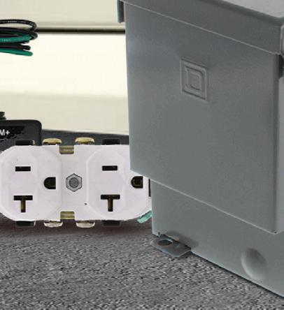

Finding the right parts shouldn’t be one of them. Save money and time when you order online. Shop for your next job at SupplyHouse.com


At SupplyHouse, we’re making it easier than ever to get all the gear you need for a job, all from one convenient place. You’ll find products, parts, and tools from the top brands. And once you place an order, we pack it right and ship it fast, so you get it on schedule. The only thing you won’t find at SupplyHouse? Challenges. 50K+ Electrical Products | Exceptional Customer Service | Leviton, Blackburn, & more

By Philip Keebler, PBE Engineers
According to the U.S. National Renewable Energy Laboratory (NREL), a microgrid is a group of interconnected loads and distributed energy resources (DERs) that acts as a single controllable entity to the grid. It can connect and disconnect from the grid to operate in grid-connected or island mode. The benefits of microgrids include improved grid resilience, reduced power outages, cost savings, enhanced energy efficiency, and integration of renewable energy.
Microgrids can operate independently during grid outages, providing continued power to critical facilities and communities. By enabling local power generation and energy storage, microgrids minimize the impact of grid disruptions.
Microgrids can also help reduce energy costs by leveraging on-site renewable energy and optimizing energy consumption. They can optimize energy usage and reduce waste by using energy storage and demand response technologies. Microgrids facilitate the integration of renewable energy sources, contributing to a cleaner energy future, and provide a dispatchable renewable energy source for electric utilities and system operators.
Each one of these benefits will improve the overall power quality (PQ) that customers require to control and reduce the cost of operating their businesses while improving the security, quality, reliability, and availability (SQRA) of the power required to run their businesses.
Applications include:
• Critical facilities: hospitals, data centers, and emergency services rely on microgrids for reliable backup power.

• Commercial and industrial sites: businesses, campuses, and industrial plants, improving operational continuity and reducing energy costs.
• Communities and remote areas: communities, especially in remote areas or those with unreliable grid connections. Smart cities can play a vital role in developing smart and sustainable urban environments.
Challenges of microgrids include:
• Regulatory hurdles: They may face regulatory challenges related to grid interconnection, safety standards, and grid services.
• Technical complexities: Managing the interactions between different energy sources and energy storage technologies can be challenging.
• Cost: The initial investment in microgrid infrastructure can be significant.
• Public acceptance: Community acceptance and support are crucial for successful microgrid deployments.
All of these challenges can be overcome by applying new technologies, engineering practices, and installation methods along with a well-trained technical staff.
Given these benefits, applications, and challenges, microgrids will require a specialized technical staff that can install, service, and maintain them in the field regardless of their location — on a hillside interconnected to a transmission grid or behind a data center interconnected to the customer’s power feeder. Providing these critical services is essential to ensure the


benefits, meet the application requirements, and tackle the challenges head-on.
This new technical staff will consist of engineers, technicians, installers, and maintenance personnel, among others. Each staff group will require specialized training customized to microgrid hardware and software components, as well as specialized skills related to
grounding, PQ monitoring, surge protection, and PQ data analysis, to name a few. Human resources from various energy-related segments can help meet the staffing requirements, but many new technical staff having little to no energy experience will be needed to fill the gaps as microgrids materialize across utility grids and customer sites.

The safety of any system must be top priority to its designers, manufacturers, testers, and end-users. Electric utilities view safety as a top priority when designing, installing, servicing, and maintaining their power systems. The safety of electric utility crews, as well as their engineering and other technical professionals, is vital to their business and the communities they serve. Electric utility power safety programs were designed and implemented based on centralized power generation plants interconnected to the transmission and distribution power system. These systems were designed to support electrical power flow in one direction.
However, with DERs and microgrids interconnected with electric utility power systems and at customer sites, power can flow in either direction. This is because DERs and microgrids serve as energy sources interconnected throughout the transmission and distribution system, including directly on customer property, serving the loads of an individual customer.
The design, manufacturing, installation, commissioning, servicing, and maintenance of DERs and microgrids must properly address the total safety requirements of each microgrid component and the system as a whole. Electric utility workers and technical staff working with DERs and microgrids must be kept safe while doing their work. Ensuring safety for the workforce requires an in-depth understanding of which DER and microgrid sources are energized, when they are energized, and when they must be automatically disconnected when unfavorable electrical conditions that could compromise safety are detected.
Improving the quality of power (voltage and current) is one of the key driving factors for the development and installation of microgrids. The inherent characteristics and engineered performance of microgrids will improve the quality of power delivered to energy users, but only if careful consideration is given to how microgrid components must be




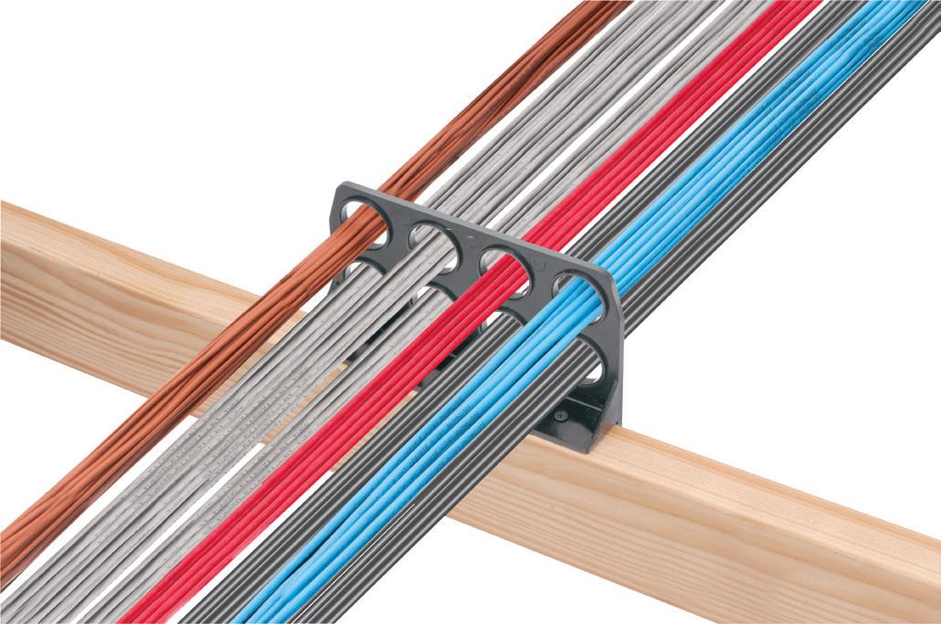
Perfect for commercial or residential applications, Arlington’s time-saving non-metallic CableAble® Support Brackets are the ONE BRACKET designed for horizontal runs of cable or conduit, commercial or residential applications, power or low voltage wiring, and plenum* or non-plenum ceilings.
• Versatile four- and eight-hole L or T style Brackets mount horizontally or vertically to wood or steel studs, and unistrut, and horizontally to all thread and beam clamps
• Multiple mounting options, secure support for EMT or flexible metal conduit, power MC and NM cables, and low voltage cables
• Load Rated for various mounting options
• For Environmental Air Handling Spaces per NEC 300.22 (c)





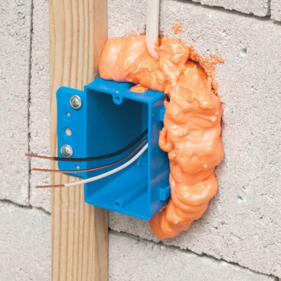


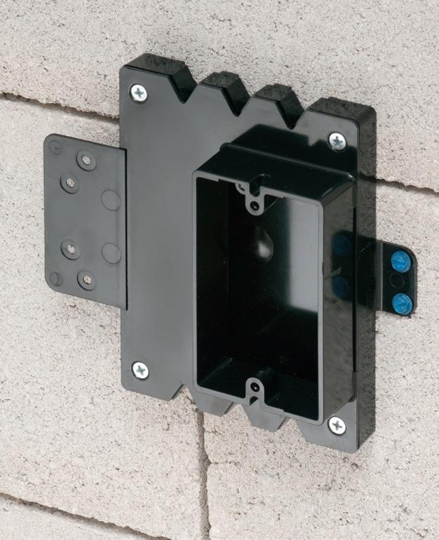
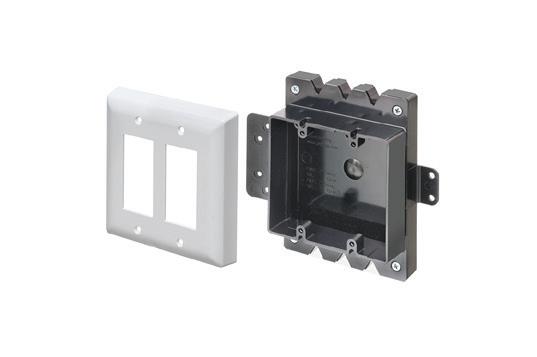
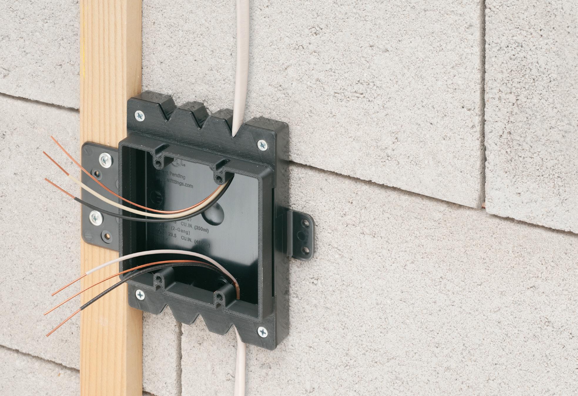
Arlington’s new Furred Wall Box® kit makes challenging outlet box installations fast and easy!
Versatile mounting options Our high strength FSB series outlet box kits are designed for use with existing 1x2 drywall furring strips – but can also be mounted directly to a concrete block wall between furring strips. Place the box or outlet where it’s needed.
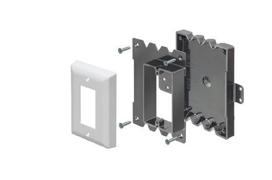
Integral cable securement – No pullout! Accommodates GFCI and USB receptacles. Convenient kits simplify ordering of FSB1 and FSB2.
High-strength No breakage in cold weather
Mounting Flanges


NEW FSB12 * FSB22
ADD OUR BOX EXTENDERS to BROADEN APPLICATION and USE
Furring strip flange Mounting Bracket
Base
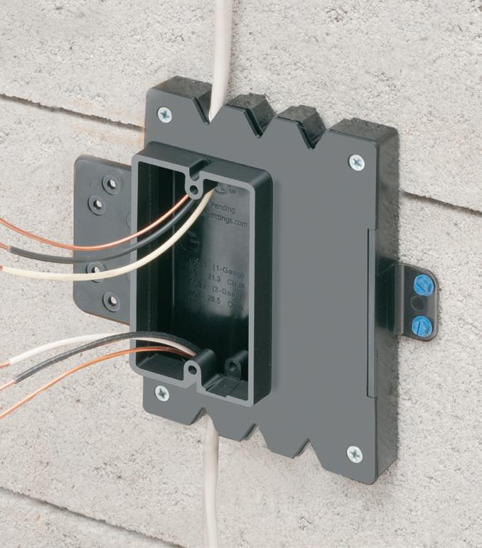
One-gang FSB12
Block wall flange Mounting
Our NEW Low Profile single and two-gang Furred Wall Box® base assemblies have 1/2" raised ring for use with standard wall plates.
They combine with Arlington’s Box Extenders to deliver installation solutions for wall thicknesses from 1/2" to 1-1/2" and varying device depths
• Integral cable securement – No pullout!
• For standard and GFCI devicesUses standard wall plates
• Single gang FSB12 - 17.0 cu. in. Two-gang FSB22 - 20.5 cu. in.


Add our BOX EXTENDERS for these specific conditions...
1 if Total Wall Layer Thickness is GREATER than 1/2" (up to 1-1/2") Add BE1 or BE2

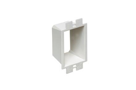

if Using a Deep Depth Device with 1/2" Wall Thickness Add BES1 or BES2


or Dimmer


compatible with each other, the grid, and customer loads. Because they can be located very close to customer facilities, they will have significantly reduced exposure to the causes of PQ problems.
Causes include the exposure of power distribution lines to foreign objects — trees, limbs, animals, other objects — and weather events that produce lightning and other disturbances caused by lines interacting with other lines. Reduced exposure to these objects means fewer disturbances (e.g., voltage sags, swells, transients, etc.) will occur, which will lower the risk of malfunctions, damage, and failure of customer power systems and their loads. When a microgrid operates in an islanding mode, disturbances caused by the common everyday grid operations cannot reach microgrid components or the customer’s building electrical system (BES) or loads.
However, because microgrids are made up of physical equipment that takes up space on customer property or in a community close to the customer’s site, they are facing new PQ challenges associated with these environments. Microgrids bring together traditional energy sources such as motor-generator sets combined with new DER technologies such as solar photovoltaic (PV), wind turbines, fuel cells, and other DER systems that use inverter-based resources (IBRs) to convert DC power to AC power. Solar PV, wind, and fuel cell-based DER technologies all use electronics in their inverters for energy conversion (i.e., converting DC to AC) as well as for controlling individual DER systems. Microgrids can also include load banks, which also utilize electronics to control load bank elements and provide their interconnection to microgrids when needed to simulate a microgrid load for testing.
Energy conversion of DC power to AC power for injection into an electric grid and/or customer facility requires the use of inverters, which are large power electronics-based “power supplies.” The inverters in DERs may be a few large single inverter systems to receive combined DC power from hundreds of solar panels or individual inverters on the backs of panels. Regardless of the power capacity of the DER, how DC power is
converted into AC power, and where the DER is interconnected to the utility or customer power system, PQ across the DER system, at the point of interconnection (POI), and along the utility circuit is critical to the success of the microgrid.
The use of specialized electronicsbased communications systems adds another layer of PQ challenges with microgrids because electric utilities and their customers must be able to actively control each component within a microgrid. Grounding for communications systems first relies on power grounding. Implementing high-performance grounding at the power system level will lower the risk of
The use of specialized electronics-based communications systems adds another layer of PQ challenges with microgrids.
PQ problems within the communications system. Communications system components must also be well protected against voltage surges, especially since microgrids will be located out in remote areas and near customer sites where the probability of lightning will be higher. Electrical noise must also be very well managed across microgrids to avoid slowing down or interrupting the communications between microgrid components and between microgrids and utility distributed energy resource management systems (DERMS).
Testing end-use electronic loads for PQ and electromagnetic compatibility (EMC) improves the performance of loads and lowers the risk of malfunctions, damage,
and failure of customer equipment. Improved performance means equipment that is less likely to have a problem when electrical disturbances occur. Equally important is customer equipment that is less likely to cause PQ problems within customer facility electrical systems and electric utility power systems. Customized test methods based on what occurs in real-world electrical environments have been developed to determine how electronic loads react to disturbances and poor electrical conditions.
The same applies to microgrids and their components. Understanding the PQ/EMC performance of the individual components of a microgrid is critical. However, understanding the PQ/EMC performance of a microgrid as a complete system, especially when it’s interconnected to an electric utility power circuit or customer power feeder and customer loads, is even more critical. This is because electrical systems as a whole are known to perform differently from their components. Electrical components always behave differently when connected in a system, especially when they are connected to other systems with a higher exposure to electrical disturbances. Understanding how microgrids as a complete interconnected system will require that on-site PQ/EMC testing be carried out as a part of the design and testing of microgrid systems.
In conclusion, the application of microgrids requires not only a diverse engineering and technical group of people but also customized education and training for those doing specific jobs related to the design, manufacture, installation, commissioning, servicing, and maintenance of microgrids. This specialized training ensures the success of DERs and microgrid installations as the world’s electrical load grows.

Philip F. Keebler serves as a Technical Advisor to PBE Engineers, LLC focused on understanding, identifying, solving and preventing (UISP) PQ problems in the industry and fostering new interest and workforce development to attract young engineers to developing careers in PQ. He can be reached at pkeebler@ pbe-engineers.com.


ABOVE)

• Easy snap-in cable installation Save time over 90° 2-screw MC Connectors at same cost per connector
• Handles widest range & variety of cables: 14/2 to 10/2 AC, MC, HCF, MC continuous corrugated aluminum cable, MCI-A cables (steel & aluminum), AC90 and ACG90
• Fast, secure installation...No pullout
• Easy to remove from box...reusable

The i-AVT Plus detects the absence of voltage and troubleshoots energized equipment in the same device. Learn more about this year’s Platinum, Gold, and Silver Product of the Year winners.
By Amy Fischbach, Freelance Writer
Two factors prompted the development of the i-AVT Plus, EC&M’s 2025 Platinum Product of the Year award-winning product — market need and market confusion.
“Electric injury and fatality trends have been steady over the last 10 years, despite intensive investment in safety awareness training,” said Edmundo Perich, vice president of sales and marketing for I-Gard Corp. “It was clear there was a need to change the lockout/ tagout (LOTO) process to be safer. This led to the development of the absence of voltage tester (AVT). The interest has been positive, although changing LOTO procedures takes time, training, and awareness.”
The i-AVT Plus combines an absence of voltage tester (i-AVT-R) with a voltage test portal (VTi) in the same product. While other individual products are available in the market, this product combination is unique to I-Gard. The two-in-one electrical safety device is designed to enhance workplace safety, streamline maintenance processes, and protect personnel/equipment from hazardous voltage risks.
“The answer was yes — but not for verifying the absence of voltage,” Perich said. “Instead, it was needed to measure voltage through a panel door in a safe manner, whether for maintenance or troubleshooting purposes.”
NFPA 70E reaffirmed this by noting in Annex 0.2.4.13 that high-impedance test points are a safety-by-design technology. As such, they allow for the measurement of voltage with the door to the electrical panel closed, thereby removing the worker from the risk of electric shock or arc flash.

While meeting a need in the marketplace, the product also helps to clear up confusion in the electrical industry. From 2018 to 2021, companies could use a voltage test port or absence of voltage detection device. Then, in 2021, NFPA 70E changed the standard from test device to absence of voltage tester.
While AVT technology is now recognized as an accepted means to verify the absence of voltage, it wasn’t clear if a permanently mounted voltage test was still a necessary and valid product.
“Armed with the information that both a voltage test port and an absence of voltage tester are needed but for two different purposes, we combined the products into a single enclosure and added a known voltage source to save time when using the voltage test port,” Perich said.
The combination product was in development for 18 months due to the complexity of SIL-3 for the absence of voltage tester.
“The biggest challenge was meeting SIL-3 requirements as required by UL1436, simply because this was a requirement we were unfamiliar with,” Perich said. “It required extensive research in terms of component selection and architecture to ensure the fail-safe requirements.”
Traditionally, the standard procedure is to confirm absence of voltage after the gear has been de-energized. Electricians then wear the corresponding PPE, open the cabinet door, and manually perform the voltage test phase-to-phase and phase-to-ground.
“This can expose the worker to a potential hazard if the equipment is inadvertently energized and/or to potential errors

Arlington’s 8X10 TV Box® with a Plastic or Steel Box offers the ultimate in versatility for installing TVs in new and retrofit projects. There's more room in the box for wires and it installs horizontally or vertically to properly position low voltage connections behind the TV.
• Ideal for home theater systems: multiple connections for sound systems, satellite TV, CATV, DVRs
• Brackets for neater cables, with a 1-1/2" knockout for ENT and other low voltage wiring


• Box mounts to stud in new work; for retrofit, mounting wing screws secure


Arlington’s non-metallic Split Wall Plates provide a simple and effective way to accommodate pre-connectorized low voltage cable(s) of varying size and quantity or pre-existing low voltage cables.
Multiple split grommets are provided with our single- and two-gang wall plates for increased versatility in effectively sizing and covering the hole/opening.
Use as shipped, or with one of the supplied bushings to alter the size of the opening.
• Single-gang CESP1 w/ 1-1/2" opening, bushings for .312" • .500" • 1" openings

• Two-gang CESP2 w/ 2" opening, bushings for .750" • 1.250" openings 1-1/





when taking the voltage measurement,” Perich said. “This product comes to solve this problem—instead of exposing the worker to an open cabinet, the worker has the means to push a test button from outside without the need of opening any doors.”
While the AVT was introduced in 2023, the combination product was introduced in late 2024 for $800 for the standard 600V model. The product is also available in medium-voltage AC and DC applications. The extension of the application now ranges from 600VAC to now 15kVAC and 3kVDC.
The absence of voltage tester, which is made in North America, does not use a lithium battery as a secondary source. Instead, the secondary source is a super-capacitor, which is maintenance free and environmentally friendly, Perich said. In addition, the UL508A-certified product, which is securely housed in a NEMA 4X enclosure, offers advanced features like automated self-checks, redundant phase and ground testing, and intuitive LED indicators.
Companies can use the i-AVT Plus in any industrial facility where LOTO is required. The initial applications are food processing, plastics, and paper manufacturers, where the incidents
of LOTO violations and penalties are the highest. When I-Gard designed the product, the main considerations were full compliance with UL1436 and NFPA 70E
The standard procedure of manually determining absence of voltage takes about 20 minutes. When using an absence of voltage tester, however, the time reduces to 10 seconds. If necessary, users can re-charge the absence of voltage tester in 20 seconds using a standard portable charger.
“There is a huge contribution to boost efficiency and reduce costs, but, more importantly, it drastically reduces the electrical hazard as the worker is not exposed to any potentially energized equipment while performing the test,” Perich said. “The voltage test port and the known voltage source mean that qualified personnel can measure voltage and ensure the correct functionality of their meter more quickly and safely than traditional means.”
Learn more about how the i-AVT Plus can enhance your LOTO safety program at www.i-gard.com/products/peopleprotection-panels/i-avt-plus.
Amy Fischbach (amyfischbach@gmail.com) is a freelance writer and editor based in Overland Park, Kan.
RVE designed the DCC-9 to allow the connection of an EV charging station to a maxed-out panel, preventing overloads and additional stress on the electrical grid. Its patented direct-to-meter wiring approach ensures seamless integration with the dwelling’s existing electrical infrastructure. By reading the total panel power consumption in real time with pre-wired current transformers, the DCC-9 detects when total consumption exceeds 80% of the main circuit breaker’s capacity and temporarily de-energizes the EV charger. The CSA-certified and UL-listed industrial load controller automatically re-energizes the EV charger once the total power consumption has remained below 80% of the main circuit breaker’s capacity for more than 15 minutes. The electricity consumed by the EV charging station is billed directly to the dwelling’s electricity bill with no management necessary. Learn more at rve-usa.com/products/dcc-9/.


The Fluke iSee Mobile Thermal Camera is a pocketsized, portable thermal camera that provides detailed image quality with high resolution (256 x 192 pixels), high temperature range (14 to 1022 °F), accuracy (±2% or 3.6 °F), and a 25-Hz frame rate. Used by inserting the hardware into a smartphone, the camera detects heat output, which can highlight abnormal temperatures. Able to be launched in 1 sec and weighing just under 1 oz., it is designed for professionals who need an easier way to capture detailed thermal images for accurate temperature readings from a safe distance or on the go. Its features include real-time high and low temperature markers with comprehensive temperature analysis for spot, line, and area and real-time image sharing. It is made of aluminum, up to 1-m drop tested, and suitable for various smart device models. Learn more at www.fluke.com.



By Randy Barnett,
From no power to intermittent faults and hidden power quality culprits, learn how to quickly identify and fix the three most common causes of branch-circuit failures.
Branch circuits are undoubtedly the most commonly installed circuits in both residential and non-residential applications. And, since they supply the equipment that utilizes the electricity, they are often in the limelight when it comes to trouble calls. Rarely is it a problem with the branch-circuit wiring itself. The cause is usually found at the end of the branch circuit — the load. In some cases, it could be other branch circuits causing misoperation of one circuit. This article first examines the National Electrical Code (NEC) definition of the branch circuit. Then, three of the most common trouble calls associated with branch circuits are explored. Finally, maintenance requirements are discussed.
A branch circuit is defined in the NEC as the conductors that run from the final overcurrent protective device in a circuit to the outlet (Fig. 1 on page 30). Note that this does not include the overcurrent protective device (OCPD) — typically the fuse or circuit breaker supplying the branch circuit — nor does it include the outlet device itself. The branch circuit is the conductors only. However, for troubleshooting and maintenance, it is practical to discuss the OCPD and the load supplied.
Following are three of the most common problems with branch circuits and tips on how to solve them.
This first one seems simple. No power — turn the breaker back on! But consider that the purpose of the OCPD is to prevent a fire. So, resetting and turning a breaker back on — or replacing fuses on a fault with excessive current flow — does not make sense. In fact, both OSHA Part 1910 Subpart S and the NFPA 70E, Standard for Electrical Safety in the Workplace, prohibit closing a circuit breaker or replacing circuit fuses until it is known that the circuit can be safely reenergized.
Therefore, finding the cause of the overcurrent device operation is the first step in solving the problem. A walkthrough of the circuit may reveal the obvious. The smell of burnt insulation or discoloration on enclosures is definitely a suspect item (Photo 1 on page 32).
Checking for trips on groundfault circuit interrupters (GFCIs) and arc-fault circuit interrupters (AFCIs) may help to pinpoint issues. For GFCI trips, look for faulted equipment or the presence of water or moisture around equipment. Tripping of AFCIs may indicate a problem with the branch-circuit conductors themselves. The breakdown of older insulation or the nail driven through the wall that nicks a wire may be the cause. Unfortunately, the AFCI trips may not be the easiest to find or repair. Depending on building age, arc-fault and ground-fault devices may not be installed per the current Code requirements (see Sidebar on page 30, “Keeping
Branch Circuits NEC Compliant”). Expanded requirements for GFCIs did not appear in the Code until the 1970s. AFCI requirements first appeared in 1999, and the number of circuits requiring such protection has increased over the Code cycles.
If a visual inspection does not reveal the obvious, meter testing is necessary to determine the cause of the trip. You must understand the circuit to troubleshoot effectively. Know your test equipment and its limitations. Short circuits are characterized by instantaneous OCPD operation caused by very low resistance between conductors. Yet, motor windings will typically measure a very low-resistance value as they are just coils of wire.
Low readings with a digital multimeter (DMM) may not always be an indication of a short circuit — a more accurate low-resistance ohmmeter may be needed. With no loads attached to the branch circuit, you should read infinite resistance between the ungrounded conductor(s) and the neutral or the equipment-grounding conductor (EGC). Also, make sure you are not checking for shorts and ground faults through parallel circuits.
Following a logical and sequential set of steps is the best method for any type of troubleshooting. The most likely cause of OCPD operation is a short circuit, ground fault, or overload. Rarely is it a faulty circuit breaker. A short circuit or ground-fault condition can be expected to trip a breaker instantaneously, while


Fig. 1. The conductors from the terminal of the overcurrent protective device for the circuit to the outlet device are the branch circuit. On this training mockup, the circuit conductors are easy to identify. In panelboards with several branch circuits, take care to properly identify the conductors of the faulty branch circuit.
an overload may take from seconds to minutes to cause OCPD operation.
If an overload is suspected, use a clamp-on ammeter to measure current flow on branch-circuit conductors while following all safety precautions for testing and measuring energized circuits. Record the amount of current that flows in the circuit. If possible, use test equipment that will record the data, since overloads may take some time to
occur. Compare readings to nameplate data and manufacturer’s instructions.
Isolating short circuits and ground faults may require additional test equipment beyond the DMM. A panelboard may require being put into an electrically safe work condition. It is generally best to begin at the source of the branch circuit — the load side of the OCPD.
Test for ground faults using a megohmmeter. Disconnect any electronics
that could be damaged by the higher voltage output of the megohmmeter. Test each ungrounded conductor from phase to ground. If any reading is less than 1 megohm, disconnect the load, and test the branch circuit and the load individually to isolate the ground fault (Fig. 2 on page 32).
Typical trouble calls: “Every once in a while, the breaker trips, and we don’t know why.” Or “Sometimes, the equipment works, and sometimes it doesn’t.” If overload conditions have been eliminated, next suspect something that can cause intermittent problems — loose terminal connections.
Faulty terminal connections can be loose, causing voltage issues. They may eventually overheat, resulting in catastrophic failure. Make sure all terminations are tightened to their specified torque values.
Improperly tightened terminals continue to be an issue with all electrical installations. It is tempting to just “tighten up all those terminal screws.” But, if not done properly, more issues may be created. Loose terminal connections increase resistance and can cause erratic equipment operation. Applying too much torque can strip
While requirements for branch circuits are found throughout the National Electrical Code (NEC), below are some Code sections to help ensure compliance:
110.7: Use the proper test equipment once branch circuits are installed or repaired to verify they are free from short circuits and ground faults.
110.8: Watch for DIYers who may have become creative! Make sure only NEC wiring methods are used for branchcircuit installation or modifications.
110.12: Be the professional! Make sure all work is completed in a “professional and skillful manner.” Close unused openings as specified in the NEC. Refer to the NECA 1-2015, Standard for Good Workmanship in Electrical Construction, and other standards as needed.
110.14 : Follow all requirements for terminals, splices, temperature limitations of terminals, and terminal connection torque.
110.17: Ensure only qualified persons (see the Art. 100 definition) service and maintain branch circuits and all electrical systems and equipment. Follow any manufacturers’ instructions, and use identified replacement parts.
110.22: Make sure all branch-circuit disconnecting means are properly identified per the Code.
210.5: When replacing conductors or modifying a branch circuit, ensure all conductors are properly identified.
210.8: There are six subsections to Sec. 210.8 covering several different applications of GFCIs. Verify GFCI protection is provided in all required locations.
210.12: Verify AFCI protection in all required locations and by the proper methods specified in this section.
408.4(A): Provide a legible and permanent description of every circuit. For panelboards, this is the circuit directory located in, on, or adjacent to the panelboard. For switches and larger circuit breakers, the description must be at each switch or breaker.
SECURE MOUNTING TO SINGLE, DOUBLE JOISTS LOWEST COST • L-SHAPED

Super-secure installation!
Our lowest cost, L-shaped fan/fixture box mounts to single or double joists





This convenient combo box has power and low voltage openings in the same box for a neat, time-saving installation.
The box adjusts to fit wall thicknesses from 1/4" to 1-1/2".
Mounting wing screws hold it securely in place.
• 2-Hour Fire Rating
• Low voltage side has a combo 1/2" and 3/4" KO for raceway
• Includes NM cable connector (power side)
Arlington’s recessed STEEL combination power/low voltage TV BOX® is the best way to mount an LED or Hi-Def TV flush against a wall.
TV BOX provides power and/or low voltage in one or more of the openings. Plugs and connectors stay inside the box, without extending past the wall.

Designed for use in new or retrofit commercial construction where metal raceway is used, we have a STEEL TV BOX for almost any application!


• Steel box; non-metallic paintable white trim plate
• Easy, secure installation
• Optional covers


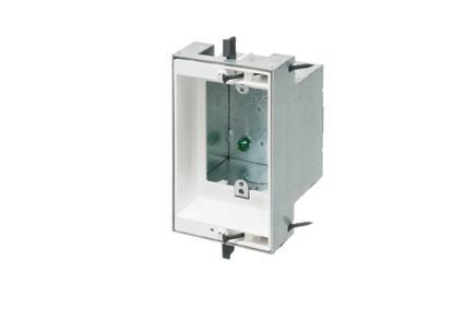


Fig. 2. A ground fault is when current flows into the normally non-current components of the system. The equipment-grounding conductor returns the ground fault current to the panelboard to allow the circuit breaker to trip and clear the fault. Use a megohmmeter to test for ground faults.
threads, distort terminals, damage the conductor, and increase resistance. Small increases in resistance values make for proportionately much larger increases in heat.
NEC Sec. 110.14(D) [Terminal Connection Torque] states, “Tightening torque values for terminal connections shall be as indicated on equipment or in installation instructions provided by the manufacturer. An approved means shall be used to achieve the indicated torque value.” Comply with the Code, follow manufacturers’ instructions, and use an approved method to verify termination torque and prevent branchcircuit overheating. See Photo 2 for one common method to verify proper torque
on branch-circuit OCPDs and outlet devices — the torque screwdriver.
If overheating and OCPD operation continue to exist, consider power quality problems. Power quality issues can be easily overlooked. Many contractors and facility maintenance staff do not have power quality analyzers to troubleshoot these problems. Personnel may not be adequately trained to measure and analyze such branch-circuit problems.
Power quality problems on branch circuits include nonlinear loads that operate either on the branch circuit or elsewhere in the distribution system. Nonlinear loads

Photo 2. Sec. 110.14 provides torque requirements for terminal connections. One method is the use of the torque screwdriver. The torque requirements are provided on the molded-case breaker. The screwdriver is adjusted by first removing the cap from the end of the tool.
are loads that rectify AC incoming power to provide DC to the circuit. Examples are computers, printers, variable-speed drives, UPS systems, and LED lighting. These loads produce harmonic currents that cause overheating in branch circuits and distort the 60-hertz sine wave, causing equipment to not operate properly. Voltage sags and swells in the distribution system may cause misoperation of loads on the branch circuit.
Power quality analysis may well isolate the problems of tripping circuit breakers when no other apparent cause can be found (Fig. 3 on page 34). Additionally, monitoring and analyzing power quality in commercial and industrial branch circuits uncovers those sometimes-unexplainable problems: Why does the breaker only trip around 2 a.m. on certain nights? What causes the VFD to trip on overvoltage when the circuit voltage is well within specifications? Consider power quality!
The NFPA 70B, Standard for Electrical Equipment Maintenance, does not address branch circuits specifically. However, it does provide maintenance and testing requirements for what is at either end of the branch circuit — the overcurrent protective devices, outlet devices, and various loads. By maintaining the equipment and devices protecting the branch and the devices and loads supplied, the integrity of the branch circuit is maintained. Given time, all electrical





Arlington’s heavy-duty Grounding Bridges provide reliable intersystem bonding between power and communication grounding systems. And handle multiple hookups of communications systems: telephone, CATV and satellite.
Our new GB5T comes with a Combination Threaded and Set-Screw hub for Threaded Rigid – or EMT Conduit.
Arlington’s zinc and bronze grounding bridges...
• Four termination points; more than required by the NEC
• Meet 2020 NEC bonding requirements for 250.94
• Fast, simple installation indoors or outside
• Textured, paintable plastic cover (except GB5NC)


• Easy access for inspections


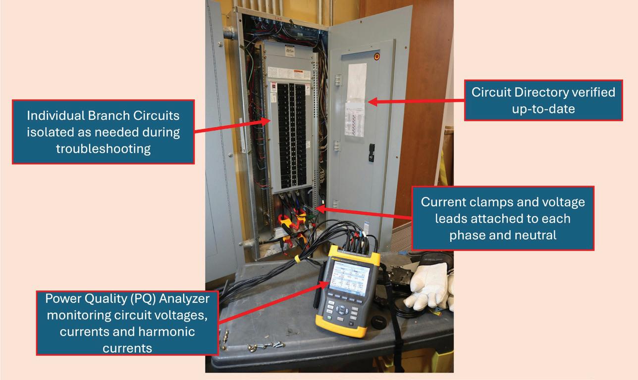
Fig. 3. Power quality issues can cause overheating, circuit breaker trips, electronic equipment malfunctions, and other issues. The PQ analyzer monitors the characteristics of the voltage and current in the circuit. Once problems are identified, different correction methods must be employed, depending upon the PQ issue, which could include excessive harmonic currents, sags and swells, unbalance, and poor power factor.
equipment degrades and will fail. Heating and cooling from current flow causes expansion and contraction of components within devices and equipment. Terminals will loosen.
To maintain branch-circuit components, first determine which branch circuits are to receive regular maintenance and what testing is to be performed. NFPA 70B provides the requirements to
select circuits and determine their required maintenance frequency. It then lists the required maintenance items and tests to be performed. Use this standard to include branch circuits in a maintenance program.
A branch circuit that fails to operate prop erly is sure to result in trouble calls. Many problems can be isolated to one of three common causes: short circuits, ground faults, or overloads. Understanding their symptoms — and how to troubleshoot and isolate them — is the job of the elec trical professional. Complying with Code requirements and combining effective troubleshooting with good maintenance practices results in less downtime and a safer installation.
Randy Barnett is an NFPA-Certified Electrical Safety Professional, a longtime journeyman electrician, instructor and author with expertise in industrial electrical construction and maintenance. He is Electrical Codes & Safety Manager for NTT Training. He can be reached at electricrb@yahoo.com.







Perfect for data center remote power panel feeds, panels, equipment feeds and EV Chargers in parking garages, Arlington’s Listed CableStop® Transition Fittings deliver the efficient, cost-effective way to transition feeder cables to 1.25", 2.5", 3" and 3.5" EMT, IMC and RMC conduit in protective drops, risers and feeds to panels and equipment. Our new CableStop fittings integrate our patented, versatile and SKU-reducing 8412 series cable fittings, with Arlington conduit fittings, allowing for easy transitions to larger knockout sizes.
Available with set-screw or compression connections into 1.25", 2.5", 3" and 3.5" conduit, they ship with multiple end stop bushings that vary the size of the opening – along with a free template select the right bushing for the cable.




From scheduled shutdowns to emergency repairs, understanding the distinct risks of planned vs. unplanned maintenance is key to safe execution.
By Tommy Northcott, P.E., Amentum
For electrical contractors, electricians, or technicians performing electrical maintenance activities in various settings, tasks can be divided into two broad categories: planned and unplanned. Planned maintenance includes activities that generally involve preventive and predictive maintenance tasks performed when the equipment can be “planned” to be taken out of service according to a schedule. “Unplanned” maintenance includes scenarios where a piece of equipment has an unexpected failure and requires immediate maintenance to make it operational again. Both categories include various hazards and risks that must be evaluated and mitigated, some of which are more obvious than others. The most powerful tool for protecting workers from hazards is knowledge. Knowing what hazards to watch out for and what tools/techniques are available for their protection helps electrical professionals spot hidden hazards before they strike.
It is often believed that planned maintenance tasks are inherently safe because there is time to plan the job and consider potential hazards before the activity begins. It certainly is true that taking time to plan the work does increase the level of safety in executing the task, which is why OSHA and NFPA 70E require every electrical task to be planned. That plan should not only outline the steps to be taken, but also identify some of the potential hazards along the way. One of the biggest risks for planned maintenance is the mindset of “this is all de-energized and safe,” which often causes workers to let their guard down. However, de-energizing the equipment is not enough; it must be placed in an electrically safe work condition per NFPA 70E Art. 120 (see Table on page 40).
Only when the equipment is in an electrically safe work condition is it considered electrically safe and free from

Arlington’s variety of cULus Listed Box Extenders extend set back electrical boxes up to 1-1/2".
Made of heavy-duty, 105°C continuous use 94V0 rated, flame retardant plastic, they level and support wiring devices, while protecting wires against damage and stripping.
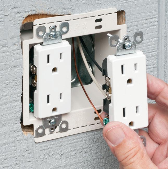

Choose the one that’s right for you!
BE1, BE2, BE3, BE4...Single-, two-, three- and four-gang, and BE1R for round or octagonal boxes...
Box Extenders


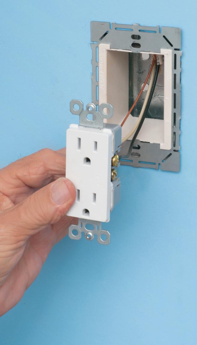

device support in oversized or mis-cut wall openings, available in single-, two-, three- and four-gang, (patented BE1X, BE2X, BE3X, BE4X.)
Our new heavy duty, COMMERCIAL-GRADE steel support plate! As shipped, single and two-gang BE1XLS and BE2XLS work with maxi cover plates, but they’re and standard plates. Convenient. Saves time. Great for poorly cut drywall.

For all standard devices, switches and GFCIs, our box extenders comply with NEC Article 314.20 for set back boxes.







• Identify all energy sources.
• Disconnect all electrical energy sources.
• When possible, visually verify disconnection.
• Release stored electrical energy.
• Release/block stored mechanical energy.
• Apply LOTO.
• Verify absence of voltage — live-dead-live method.
• Properly ground all circuit parts, if feasible.
NFPA 70E, Sec. 120.6
electrical hazards. However, one often overlooked hazard comes during the process of putting it in and out of that electrically safe work condition. Depending on the equipment and the voltage levels, the act of opening and closing the means of disconnect could pose an electrical hazard.
A risk assessment must be performed to determine what electrical personal protective equipment (PPE) is required to operate the disconnect device. Putting the equipment back into service after maintenance can carry even more risk due to potential human error. Devastating equipment failures have occurred as a result of a protective ground being left on a conductor inside an enclosure.
It is a best practice to give all protective grounds a unique number, and — as part of the maintenance procedure — document which ground is placed at which location. Then, at the end of the task, document each ground as it is removed and compare to the initial list to make sure all grounds that were installed are documented as being removed. In addition, if a ground is placed inside of a closed compartment, put a magnetic sign or flag on that compartment as a visual reminder that a ground is installed inside the compartment.
Another aspect of establishing an electrically safe work condition that involves a potential electrical safety risk is verifying the absence of voltage. Since the equipment is in the process of being placed into an electrically safe work condition (but the process is not complete), the equipment and conductors are still to be treated as energized. During the process of verifying the absence of voltage for any circuit rated 50V or greater, voltage-rated gloves and protectors must be worn as a minimum. Depending on the voltage level and incident energy levels, arc flash PPE may also be needed while performing the live-deadlive method to verify the absence of voltage.
The live-dead-live method is the process of using a properly rated digital voltmeter to check all phases and ground to verify the absence of voltage. Ideally, the meter is used to check the voltage on a known energized source of the same nominal voltage to verify that the meter works. Then, without making any changes to the meter, check all phases and ground for all the circuits involved in the maintenance task to confirm the absence of voltage. Then, go back to the known energized source to confirm that the meter is still working. The live-dead-live method eliminates the risk of a meter failure or operational error by including steps to confirm the functionality of the meter.
Another risk to consider and evaluate is the potential hazards associated with what is in the proximity of where the maintenance task is being performed. Too often, workers get narrowly focused on only the specific equipment that is being worked on and overlook hazards in the surrounding area. Workers must do a risk assessment on the area and consider all hazards to which they may be exposed. They must verify that they will not be working within the limited or restricted approach boundaries of any other exposed energized conductors or take appropriate mitigation steps if they are inside one of those boundaries. A large enclosure may contain two systems: one that is in an elec trically safe work condition for maintenance and one that is still operational. Often, there is other electrical equipment adjacent to the work area that remain energized. If there is “look-alike” equipment in the same area, consider using the “tape in” and “tape out” technique to avoid inadvertently opening the wrong equipment. Place warning tape/signs on the equipment that is still energized to keep workers out, and place barriers or tape to help guide workers to the electrically safe equipment.
Thermography or infrared (IR) inspection is a predictive maintenance activity that continues to become widely used by more organizations. Thermography can reveal develop ing abnormalities well before they trend to failure, allowing the opportunity to plan a downtime to make a repair and avoid the looming unplanned outage due to equipment fail ure. For thermography to be effective, the equipment must be energized and ideally heavily loaded. In addition, the ther mography camera needs to have a direct line of sight on the conductors or parts needed for inspection, which means the conductors or parts are typically exposed.
Opening and closing enclosures of energized equipment can be a hazardous activity, especially while wearing voltage-rated gloves and arc flash PPE. A better alternative would be to deenergize the equipment, remove the necessary covers, barricade the area, and then re-energize the equipment for the inspection. A best practice would be to mark the area on the enclosure where the components that need to be viewed for inspection and install infrared (IR) windows at those locations. Then future inspections would not require opening the enclosures, but simply viewing the equipment through the IR windows.

Unplanned maintenance can include the same hazards and risks as planned maintenance, but it also has some unique aspects to consider. When an unplanned maintenance task comes up, it is typically associated with an outage of some kind. Something has failed, and someone is without power or some other service that they need. This scenario promotes a sense of urgency to restore the system to normal. Often, the impacted individual is hovering around watching the electrical workers doing what is needed to bring the system back into service, which just adds to the pressure that the electrical workers feel. This pressure can make it tempting to take risks or shortcuts to try to get the issue resolved as quickly as possible. However, it is never worth the risk to put one’s safety in jeopardy over an inconvenience. The best thing to do is to evaluate the situation and start developing


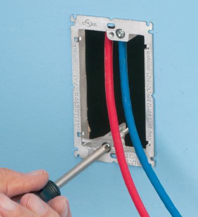


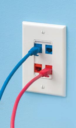

Arlington’s Low Voltage Mounting Brackets are the solution for fast and easy cut-in installation and mounting of Class 2 communications, computer and cable TV wiring and connections.
Introducing METAL low voltage mounting brackets for EXISTING or RETROFIT construction...
LV1M and LV2M COMMERCIAL GRADE
• Extra rigidity and stability where performance and visibility are important or critical
• Threaded holes for easy, fast device installation
• Adjustable bracket for 1/4" to 1" wall board thicknesses
Our LV1S and LV2S PLATED STEEL bracket design, provide excellent stability and secure installation of low voltage devices in 1/4" to 1-1/4" walls - without an electrical box.




a plan and risk assessment before just jumping in and starting to troubleshoot the problem.
Due to this sense of urgency and pressure surrounding the unplanned outage, there is the risk of forgetting to or being tempted to not put the affected system in an electrically safe work condition before starting to work on it. Article 110 of the NFPA 70E requires that electrical conductors and circuit parts equal to or greater than 50V shall be put into an electrically safe work condition unless it is infeasible to perform the task in that state.
Taking voltage or current readings would be an example of something that is infeasible in an electrically safe work condition. Inconvenient is not the same as infeasible. Sometimes, it is necessary to take additional circuits or systems offline and place them in an electrically safe work condition to safely make the repair. This is another time when the pressure is on, and workers tend to get tunnel vision, often focusing on the specific impacted circuit or system. It is best to periodically step back and get a view of

the big picture to ensure there are no adjacent hazards that are being overlooked. Hazard elimination is to be the top priority throughout the entire task.




Another aspect of an unplanned outage is not just getting the system back online, but understanding what caused the failure. Will it happen again? Is there an increased risk of catastrophic failure when the system is ready to be brought back online? The root cause needs to be determined and understood to mitigate the risk of a repeat failure. Even if there was no equipment failure, NFPA 70E Sec. 130.8 prohibits the reclosing of circuits after protective device operation unless a qualified person has determined the equipment and circuit can be safely energized. This becomes even more important after a component or system failure. Have a qualified person investigate the failure and perform a root cause analysis to determine the most likely cause for the failure and make sure that the root cause issue has been corrected or mitigated.
All electrical tasks should be properly planned and evaluated through a risk assessment before beginning work — even if the task is an unplanned maintenance activity. Hazards can appear in various shapes and forms, so it is important to always make it a habit to look for them — and , once they are identified, determine how to mitigate them. When you find yourself “in the moment,” take a few minutes to step back, slow down, think things through, and get a renewed view of the complete picture. Hazard elimination needs to always be the priority. For electrical hazards, this comes in the form of establishing an electrically safe work condition for anything that is exposed during the task.
Any opinion expressed in this article is the personal opinion of the author and does not necessarily represent the official position of the NFPA or its Technical Committees.

Arlington’s Concrete Pipe Sleeves are the economical way to sleeve through concrete pours in tilt-up construction WALLS – and FLOORS allowing cable and conduit to run easily from one floor to the next.
No costly core drilling – No cutting holes in the form. Plus, you can position the hole prior to pouring the concrete.
• Attaches to form with nails or screws
• Stackable up to 23" h for extra deep pours
• Vents keep wet pipe sleeves from sticking together
• Multiple hole sizes: 1-1/2" • 2"




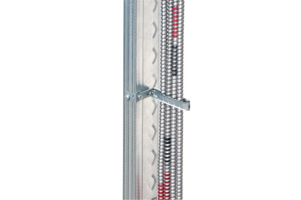
economical CUS6 galvanized steel Cable Support holds cable secure and centered on a metal or wood stud.
perfect for fastening and
or


to a wood or metal stud, and position the cables. Next bend the strap at the foldline (centerline). Fold the strap over the cables and insert the locking tab in the opening as shown to hold




By Jason Faircloth, Southwire Solutions
Field-tested ways electrical contractors can improve efficiency and increase profit margins
In the construction industry, creativity and innovative problem-solving play crucial roles alongside standardization in driving success. This article explores five key ways that harnessing job-site ingenuity can significantly enhance profitability for electrical contractors, particularly in an era marked by labor shortages and increasing project complexities.
In an economy and industry where labor shortages abound, finding and retaining top talent is difficult because electrical professionals are often asked to perform time-consuming, labor-intensive tasks that take their attention away from more specialized work. According to the study, “Ideal Jobsite Inventory Levels to Improve Profitability,” conducted by MCA, Inc. on behalf of ELECTRI International, skilled electricians spend up to 40% of their time on material handling. With labor shortages expected to continue, contractors must maximize efficiency with their teams.
In one example, a project originally estimated to take 17 days of labor with a six-person crew saw a significant reduction in installation time through a simple yet innovative adjustment in the planning phase. The project’s original timeline was largely influenced by the manual handling of traditional cable reels. By introducing a creative reel payoff system, the installation time was reduced to just three days, allowing a single worker to reposition the reels efficiently and safely. This change not only


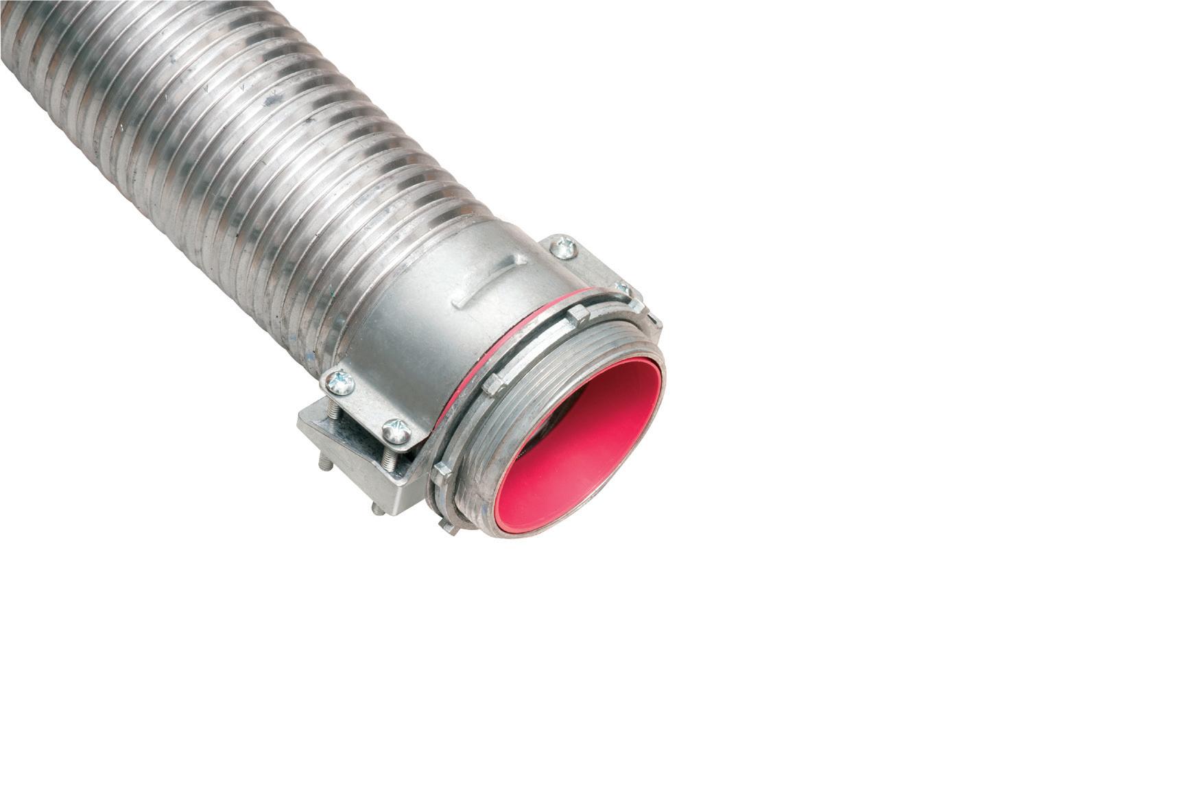
* Aluminum & Steel Flexible Metal Conduits


ONE trade size fits SEVERAL cable types and sizes, plus flexible metal conduit for super convenience and cost-savings! Reduces inventory and material handling too.

Patented
Conductor Size CSA TECK90 Conductor Size # of Conductors* # of Conductors* (AWG/KCMIL) (AWG/KCMIL/ACWU) 6/3, 6/4, 4-3, 4-4, 8/3, 8/4, 6/3
2-3, 2-4, 1-3
2-3, 2-4, 1-3, 1-4, 6/3, 6/4, 4/3, 4/4, 3/3, 1/0-3, 1/0-4, 2/0-3, 3/4, 2/3, 2/4
2/0-4, 3/0-3
2/0-4, 3/0-3, 3/0-4, 2/4, 1/3, 1/4, 1/0-3 4/0-3, 4/0-4, 250-3, 250-4 1/0-4, 2/0-3 250-4, 300-4, 350-3, 2/0-3, 2/0-4, 3/0-3, 3/0-4, 350-4, 500-3 4/0-3, 4/0-4, 250-3 500-3, 500-4, 600-3 4/0-4, 250-3, 250-4, 300-3 600-4, 750-3 300-4, 350-3, 350-4, 500-3 600-4, 750-3, 750-4 350-4, 500-3, 500-4 750-3, 750-4, 1000-4 750-3, 750-4, 1000-3

streamlined the process but also resulted in substantial cost savings of more than $80,000, highlighting how optimized planning and improved tools can reduce labor time and enhance safety — all while maintaining high productivity.
The most effective electrical contractors plan for potential pitfalls and preemptively ensure efficiency-saving measures and equipment are already in place to keep the project running smoothly and profitably. But even the most prepared teams will run into unexpected challenges on site.
Electrical work often takes place at the same time that other trades are working, or is dependent on other trades’ work being completed. It also relies on construction drawings; sometimes, there are discrepancies between the drawings and what the different trades have done. When that happens, rapidly finding workarounds to job-site challenges can be the difference maker when it comes to staying on schedule. However, even creativity can benefit from a standardized process in the construction industry. For instance, contractors with a transparent and standardized communication process can quickly navigate to a solution when a challenge arises on site.
Front-line installers should be able to promptly communicate their issues and suggest solutions to site leaders, who can contact project stakeholders for rapid
approvals and accurate instructions. The more efficiently communication can flow, the more effectively work can be completed — and the better the chances are the project will stay on schedule.
Another suggestion is to include the design firm and any upstream suppliers in the problem-solving process and request that they create a guide for implementing innovative solutions. By creating a reference guide for these solutions, contractors can standardize responses for future projects with similar challenges.
Recognizing creative thinkers and problem-solvers in team meetings is an excellent way to create a culture of innovation in your company. If a team member went above and beyond to find a solution to a site challenge, highlight them in your next safety huddle or site trailer meeting by sharing the issue they identified, how they solved it, and the benefit and/or result. As the crew sees colleagues’ efforts resulting in praise and attention, they will feel more comfortable contributing in similar meaningful ways in future challenging situations. However, recognition should be handled carefully. If a creative solution was attempted but fell short in execution, constructive feedback should be delivered privately. The last thing you want to do is stifle creativity in the team by calling out a faulty attempt
at creative problem-solving. Doing so will only result in an embarrassed team member and a tight-mouthed, unimaginative crew.
A culture where innovation is continuously celebrated will breed more innovation. By being acknowledged for contributions to the success of a project, an electrician will be more heavily invested in future projects. And the more invested front-line installers you have, the more productivity and profitability will continue to grow.
Differentiating your company as one that promotes creativity and celebrates innovative thinkers will separate you from the more rigid contractors in the field, helping you attract more clients and top talent. New entrants into the electrical installation field usually have a choice when it comes to where to work. Younger workers are more likely to seek employment with companies that have a positive reputation, promote inclusivity, and see value in employee ideas. Innovative contractors will also attract top talent in more experienced roles to help lead the next generation of workers.
Similarly, customers are looking for contractors who can plan for efficiency, think on the fly, and quickly resolve issues — all while staying on time and on budget. Customers want to know they can trust their contractors to resolve problems without needing to take up too much of their time.
With an eye on profitability, building owners and general contractors are also paying more attention to which electrical contractors are adopting the newest timesaving, future-ready technologies. Leading-edge contractors offer added value to customers in the form of staying on track or recovering schedule time and avoiding costs associated with injury downtime. These value-adds often outweigh the possible associated minor cost differences. They will also be looking for partners that are continuously adopting the newest technologies so that when they want to make upgrades, they know their contractor is already upskilled and ready to take on the new assignment.


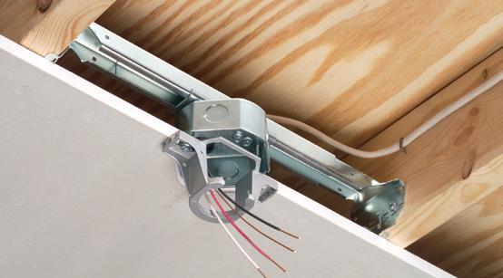
Arlington’s heavy-duty, plated steel fan/ fixture box has an adjustable bracket that mounts securely between joists spaced 16" to 24" o.c.
Flush ceiling installations

FBRS415 is designed for ceilings up to 1-1/4" thick. For 1/2" ceilings, use the pre-bent positioning tab. For other ceiling thicknesses, bend along the appropriate score line.
• 15.6 cu. inch box ships with captive screws, mud cover, installed NM cable connector





Technology advancements in construction have made considerable improvements in job-site efficiency. One example is off-site construction techniques, or prefabrication, which have significantly streamlined unpredictable job-site processes. Electricians can eliminate unforeseen on-site circumstances by completing specific repeated steps in an off-site controlled environment. In addition, more extensive inventories of parts and materials are immediately on hand, and improved quality control measures can be implemented. For instance, assembling conduit racks in a clean indoor setting is far more efficient than a potentially freezing, muddy job site. In addition, many electrical manufacturers test the entire assembly and provide
facilities, such as data centers, contractors can try out a proposed change and compare labor figures for a scientific measurement of increased productivity. Utilizing A/B testing in this way can help them move toward more productive standard operating procedures and stand out in a crowded and competitive field. AI is touching every industry, including construction. By utilizing predictive analytics, it can help to streamline repetitive and time-consuming tasks. For example, by leveraging AI to capture previous failure points or issues resulting in callbacks, contractors can quickly identify commonalities and train teams on specific problem areas for further improvement. AI and machine learning are also rapidly sweeping through the supply chain with promising and significant benefits to advance manufacturing.
solutions can lead to reduced labor hours and costs, while a tailored project approach with standardized communication processes ensures projects remain on schedule and trades teams collaborate effectively. At the same time, recognizing out-of-the-box problem-solving from crew members can help foster a culture of creativity and boost team morale. Furthermore, as an innovative leader in the industry, you position your company to have a competitive advantage, attracting both clients and skilled talent. By adopting standardized best practices with forwardthinking solutions, electrical contractors can not only enhance their profitability but also pave the way for a brighter, more innovative future in the industry.
Jason Faircloth is the Director of Southwire Solutions. As the leader of Southwire’s Contractor Solutions Organization across the US, Jason and his team spend their time training contractors on the benefits of adopting the most recent technology to make their work more safe, more efficient, and ultimately, more profitable.


MM18
J-channel covers cut ends of siding
Remove flanges for retrofit work
Arlington’s one-piece, non-metallic Mounting Bases provide a smooth, flat mounting surface for most electric meters, including the largest sizes – as well as a variety of other products such as timers, disconnects, inlet boxes and more.
UV rated, paintable plastic for long outdoor life.
Squared-off corners make them gangable so you can create the mounting base needed for the product you’re installing.

Gangable...for custom sizing



MM7 info aifittings.com/landing/mm7 Other aifittings.com/landing/meter-mounting-bases


In a tight spot? Arlington’s new SNAP-TITE® Transition Fittings offer the time-saving solution for installing additional conduit or cable in an already congested panel. They allow installers to work around tightly spaced, installed fittings in a panel, box or enclosure – where installing and tightening additional locknut fittings would be


Convenient, Time-Saving snaps into a 1/2" knockout and connects 1/2" trade size threaded fittings or pipe. aifittings.com/landing/2450st


From early mornings to late-night service calls, this snapshot of residential electricians reveals the skills, tools, and training behind one of construction’s most essential — and often overlooked — professions.

By Harold De Loach, The Academy of Industrial Arts L.L.C.
What does a day in the life of an electrician actually look like? Given the fact that the broad EC&M audience works in so many vertical markets and industries, we thought it would be valuable to develop a series that showcases the different types of environments they work in, what types of electrical equipment they install, troubleshoot, or maintain, and what it takes as far as education and training to succeed in each field. This introductory article takes a closer look inside the wiring at what it takes to power America’s homes.
As the Director of Education and Training for the Leaders of Electrical License Preparation courses for Philadelphia and The Lehigh Valley and founder/director of The Academy of Industrial Arts (TAIA), a customized electrician training program that provides entry-level electrician training courses, electrical safety classes, and customized electrical construction courses, I have had a front-row seat over the years to determine what it takes to train all types (entry, intermediate, and master level) of electricians to go on and succeed in various industries/environments.
Residential electricians are the backbone of the construction industry. They ensure customers have power and lighting to meet all of their basic electrical needs at home. The typical pathway into the electrical trade for most electricians starts in residential wiring — the most basic and simplest form of circuitry in construction.


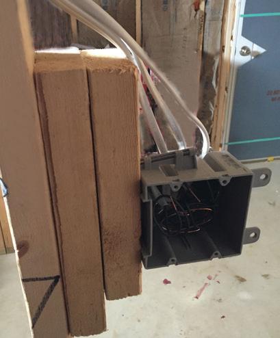


Arlington’s steel SliderBar® offers the easy, NEAT way to mount single or two-gang boxes between wood or metal studs with non-standard stud cavities.
No more cutting, nailing and fitting extra 2x4s to fill the space! SliderBar saves about 20 minutes per box. Designed for studs spaced 12” to 18” apart, SL18 allows positioning of one or more boxes anywhere in the stud cavity.
• Bending guides on bracket assure proper positioning on studs
• Interlocking tab stop prevents accidental disassembly


• Pre-punched pilot holes on BOTH sides of S for easy attachment of one or two boxes
According to the Bureau of Labor Statistics, there were more 202,000 residential electricians currently employed in the United States in 2023. Of that total, only 3.3% were women, and the average age of a residential electrician was 41. These electrical professionals repair, install, and maintain equipment, such as receptacle outlets, ceiling fans, luminaires, circuit breakers, and panelboards. They also perform service calls when things stop working in a home, condo, or an apartment.
Predominantly serving a small, specific geographical area, town, borough, or city, residential electricians build a strong reputation in a community and usually work in that general area all year — travel to other states and geographical areas is not normal. They are also typically paid daily, hourly, or weekly.
Here are some examples of common service calls performed by residential electricians:
• Main service upgrade
• Panelboard changeout
• Installing recessed lighting
• Replacing failed circuit breakers
• Adding dedicated circuits for special appliances
• Troubleshooting old knob and tube wiring systems
• Replacing or installing smoke detectors or carbon monoxide detectors
• Installing outdoor lighting and receptacles for the holidays
These types of services are typically performed by medium-sized contractors (employing 25 to 100 electricians) or small mom-and-pop shops (often employing two to 24 electricians). Large electrical contractors routinely focus on commercial and industrial projects, which will be discussed later in this series.
One trick of the trade you’ll usually find among residential electricians is they get up early. They’re on the road before the rest of the workforce to prepare for the day ahead. Organized residential electricians prepare their materials before the job starts (e.g., painting mounting boards and “making up” service heads the night before). This saves hours of installation time on service upgrade jobs. Their workday typically begins at the “shop” to meet the “boss” and get material and assignments before “rolling out.” They often work in teams of two to three (although some work alone) with part-time helpers.

Apprentices often ride shotgun in the company vehicle with the owner, a journeyman electrician, or a lead technician. Supply house runs are usually the first stop for smaller residential contractors. Large companies warehouse their own material inventory to save time and take advantage of bulk discounts offered by the distributor. Vans are stocked with everyday items electricians use on a regular basis (see the Sidebar “What’s in the Van?” on page 52 for a list of products typically found in a residential electrician’s service van).
There are two types of residential electricians: “old work” and “new work.” Old work electricians work in existing homes that may be currently occupied by residents or tenants. These homes or apartments have finished walls, ceilings, and flooring. Work in existing homes can be time-consuming and requires significant patience. Electrical problems are usually due to a bad or faulty single-pole or 3-way switch, which may take 30 minutes to diagnose and repair, or a defective or malfunctioning circuit breaker or fuse, which usually takes 45 minutes to diagnose and repair. Replacing the failed device or tightening a connection often fixes the problem.
A typical service call for residential electricians is for “non-working” receptacles, due to the overloading of an electrical circuit caused by portable heaters, air conditioners, or loose connections within the circuit. This problem requires more time to diagnose or repair if the home has older “knob and tube” wiring (a wiring system that dates back to the 1800s); it can take an hour or more to diagnose in some cases. The worstcase scenario is when it takes all day to trace a circuit throughout a house (sometimes cluttered or messy) to remedy or repair the problem. A common issue in a home with older wiring is broken neutral wires within the walls and improper backstabbing of wires at receptacles. This means using the push-in method to wire a duplex receptacle — and that’s a poor method to feed power downstream to other outlets.
“New work” residential electricians are vital to builders during the early stages of a construction/building project; they provide the temporary power to the job site for lighting and tools that other trades need for the project’s duration. New construction electricians typically work on single-family homes or multi-family dwellings with exposed


Arlington’s one-piece Snap2It® STEEL connectors offer easy, secure installation. And save time! Just push the cable into the connector and rotate the connector clockwise.

• Tested to UL 514B and Listed to meet UL ground fault requirements
Available in 3/8" trade size, both connectors install into a 1/2" knockout, and are Listed for steel and aluminum AC, HCF, MCI and MCI-A cable. In Canada both connectors are Listed for use with AC90 and ACG90 cable.
The tinted 40STS has more room inside for easier cable insertion.
* UnSnapIt Removal Tool offer good on 50-pc orders onlywhile supplies last
• Removing the connector from cable Unscrew the connector counterclockwise to remove it from the cable.
from the box Use a screwdriver to separate the snap ring OR use our NEW easy-to-use UnSnapIt ™ Removal Tool!
• Packed in NEW 50-piece or 200-piece boxes



walls and ceilings. For a new electrical apprentice, residential new construction installations go much faster, fall on the simpler side, and are more manageable. Installing electrical systems in newly constructed buildings is often less complicated than working in existing buildings because electrical wiring is
easily accessible during the construction phase of a home or apartment building.
Residential electricians rely on a basic set of hand tools (e.g., cutters, screwdrivers, and a hammer), a few power tools (e.g., drills and saws), and a strict adherence to the requirements in Chapter 2 (Wiring and Protection)
Following is a list of a few common essential tools/materials most residential electricians carry to the job site:
• Single-pole switches
• Single-gang toggle plates
• 15A duplex receptacles
• Plastic duplex cover plates
• 15A ground fault circuit interrupters
• 3-way switches
• Metal old work device boxes
• 4-inch round metal octagons
• PVC old work device boxes
• 100A service panels
• 200A service panels
• #2 AWG aluminum service entrance cable unarmored
• 4/0 aluminum service entrance cable unarmored
• Ceiling fan mounts with brackets
• Metal handy boxes
• Drop cloths
• Booties
• Face masks
• Vacuum cleaners
• Cement mix
of the National Electrical Code (NEC). These Articles cover the “planning stage” of an electrical project and can take time to learn. For example, mastering the requirements for “dwelling units” can take a few years. They must also have basic and advanced knowledge of building materials. Electricians and apprentices should know what building materials are acceptable to secure, fasten, and support electrical equipment and devices, such as luminaires, ceiling fans, surface-mounted boxes, and other electrical equipment.
Selecting the appropriate bolts, fasteners, screws, supports, and fittings is essential. Choosing improper products or accessories can cause damage to the property or lead to equipment failure. For example, fasteners have weight limitations and are recommended for use with specific building materials like wood versus metal or concrete versus cement. Electricians also need to know time-tested methods for fastening electrical boxes and equipment on or within walls, ceilings, and building surfaces, such as plywood, concrete, drywall, or brick for installing electrical equipment.
• Drywall plaster patch
• 2- to 4-foot ladders
• 6- to 8-foot ladders
• 10- to 12- foot ladders
• 18- to 32-foot extension ladders
• #18 AWG copper thermostat wire
• #10 AWG NM copper wire
• #12 AWG NM copper wire
• #14 AWG NM wire
• 2-gang plastic toggle plates
• 3-gang metal toggle plates
• 4-inch by 4-inch square metal junction boxes
• 1/2-inch NM wire connectors
• 1/2-inch metallic wire connectors
• 3/4-inch metallic NM wire connectors
• Trash bags
• 1/2-inch PVC conduit
• 2-inch PVC conduit
• Single-pole circuit breakers
• Double-pole circuit breakers
• Smoke detectors
• Doorbell chime kits
• LEDs
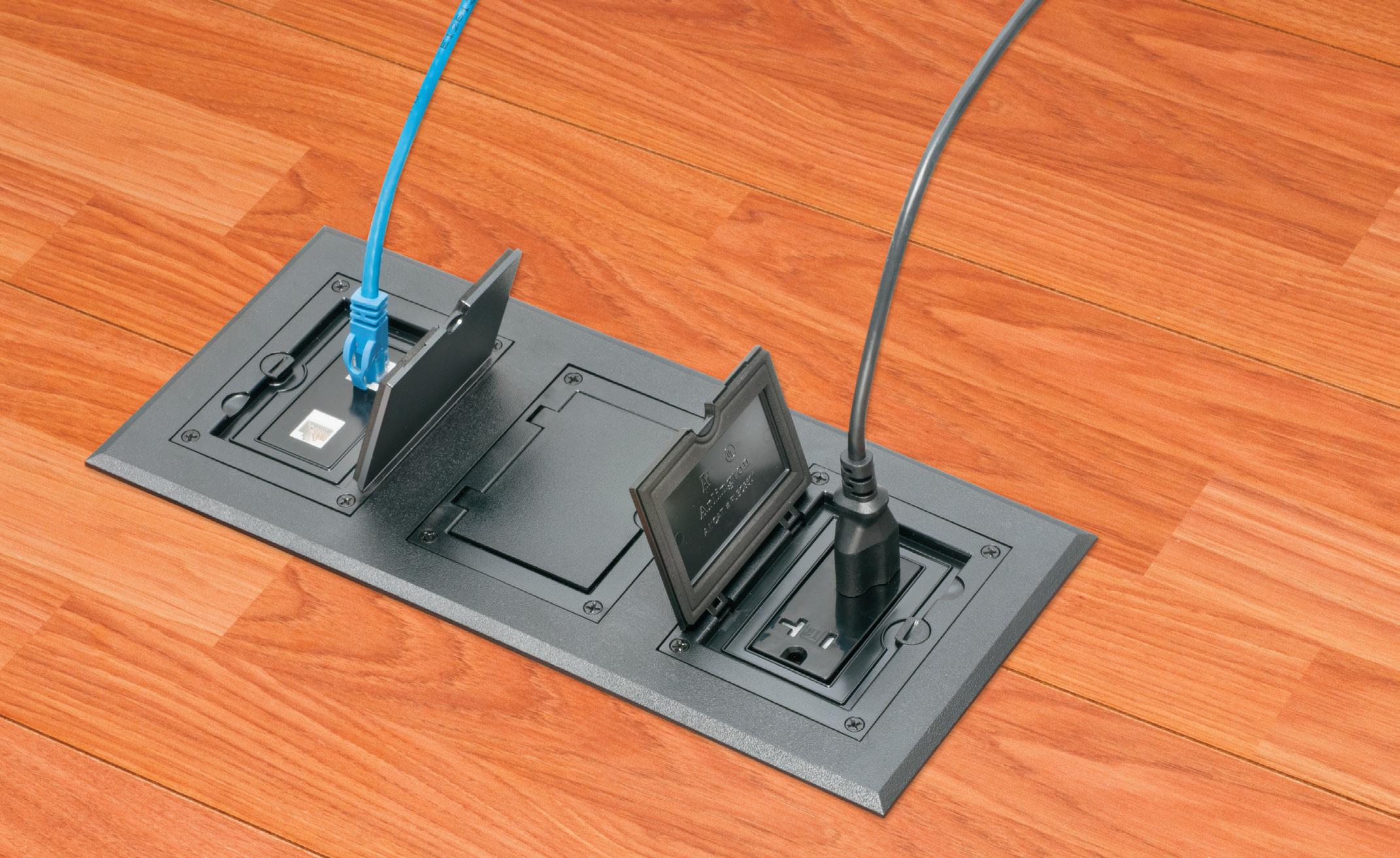
Side connections lock single gang FLBC8500 boxes together

Single gang box
(3) FLBC8500 boxes
(1) FLBC8530BL Black PLASTIC cover/frame kit







Lock two boxes together for a two-gang box. Add another for three-gang!
Here’s the easy way to add receptacles in a commercial concrete pour. Lock single gangable boxes together to build a two- or three-gang floor box!
Then add the UL LISTED single, two- or three-gang Cover/Frame kit, with devices included.
• PLASTIC in Black, Brown, Gray, Light Almond, Caramel...
• DIECAST ZINC with a Brass or Nickel finish... Furniture feed inserts also available with brass or nickel finish
• PLATED, PLASTIC or POWDER-COATED with Flip Lids
Fast, easy cover installation. Installs with hinge on either side.


Electricians need to know what materials are approved for specific uses such as receptacles and luminaires. For example, Sec. 410.10(A) of the NEC states: “Luminaires installed in wet or damp locations shall be installed such that water cannot enter or accumulate in wiring compartments, lamp holders, or other electrical parts. All luminaires installed in wet locations shall be marked ‘Suitable for Wet Locations.’ All luminaires installed in damp locations shall be marked ‘Suitable for Wet Locations’ or ‘Suitable for Damp Locations.’”
Receptacles are rated for “outdoor” wet location use versus “indoor” dry location use. Apprentices need to know the mechanical strength and durability of electrical materials (e.g., wire, receptacles, boxes, and connectors) to create reliable grounding and bonding connections throughout an electrical system. They need to know the acceptable use, selection, and suitability of electrical equipment, devices, panels, and fittings for specific purposes by the Authority Having Jurisdiction (AHJ).
Residential electricians should have a basic understanding of wood and light metal framing techniques for homes and apartments. Understanding the layout and location of other mechanical systems in the house or multi-family dwelling (e.g., plumbing, heating/air, existing electrical lines) comes in handy when “fishing” in new wires or modifying existing circuits and is beneficial to avoid damage to the property and existing wiring systems.
It’s also important that a residential electrician learn cost-effective methods of using materials efficiently and to shorten the construction or repair time, such as patching walls and ceilings, repairing bored holes in cement and concrete. Knowing the tolerances of lumber and joists before cutting or altering them for electrical installations is crucial. An understanding of the difference between load-bearing and non-load bearing walls is also essential.
The number of service calls that a team of two electricians may respond to daily can range from one to five jobs per
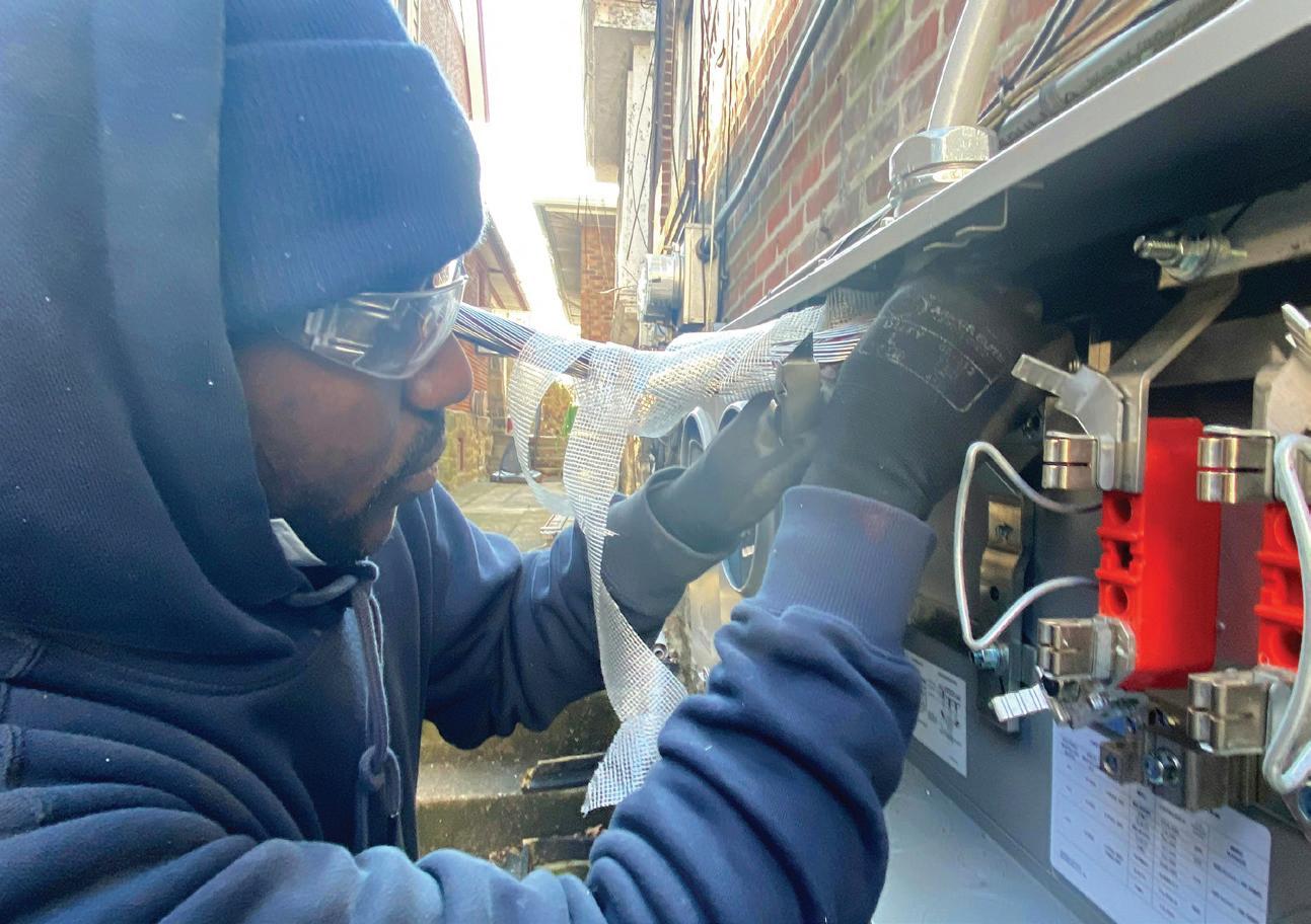
8-hour day. A service call with the highest level of difficulty can take up to a full 8-hour working day, while the shortest time required to complete a service call could be only 30 to 45 minutes.
At larger shops, residential electricians typically work 40 hours per week Monday through Friday — weekends and overtime are usually optional. Electricians and apprentices from smaller mom-and-pop shops, however, work later and on some weekends; a typical day could start at 7 a.m. and end around 9 p.m., to keep up with service calls and the pace of construction. During the warmer “summer” months (peak season), a 60-hour work is typical at smaller residential contractors; it slows down during the colder months. Home renovations for kitchens, bathrooms, and additions peak during the warmer months; the option to work overtime and weekends at smaller shops typically runs throughout the entire summer, when demand is this high.
In general, electricians have very little educational debt, if any. A lot of residential electricians learn in the field from “seasoned” experienced electricians while on the job. Others may learn the skill through a local trade school or college by completing a certificate or diploma program. These are short programs that typically run for six months full time (just a few nights a week) or part-time for about nine
months (one night a week). The costs for “electrical technician programs” or residential “wireman” programs range from $2,000 to $9,000. The curriculum for these programs includes electrical theory; basic electrical safety; residential blueprint reading; residential electrical calculations; residential equipment and material selection; and residential and multi-family service equipment selection and sizing.
The exams required to pass these programs are usually created by the course instructor or from a nationally recognized curriculum approved by the state with an “intermediate level” of difficulty to pass, including basic math (e.g., multiplication, division, addition) and a general understanding of the NEC and related formulas. Completing certificate and training programs is a great way to get started in the electrical industry and secure opportunities for job interviews at a local company — but make sure you get some field experience while you’re pursuing this certificate or diploma. Bosses like to see field experience coupled with education.
What one person considers a con, another might see as a pro. It really depends on the individual. Many electricians embrace these aspects of their work, but here are some potential advantages/drawbacks that are commonly cited by residential electricians.


If you’re weighing the potential benefits of this career path, many residential electricians find the following aspects of the work rewarding:
• Favorable working conditions
• Optimistic job growth forecast
• Minimum travel required (usually)
• Short training programs available (nationally)
• Requires less training and continuing education requirements
• Abundant opportunities during peak season (warmer months) While many electricians find the work fulfilling, it’s important to understand the potential challenges that come with the job. Following are some common drawbacks noted by residential electricians:
• Flat pay scale
• Physically demanding and sometimes dirty work
• Unconventional or inconsistent hours
• Weather exposure
• Highly cyclical (seasons affect demand and pace) of work and employment opportunities
• On-call or emergency work
• Risk of injury
There are abundant opportunities for residential electricians. According to ZipRecruiter, as of August 2025, the average hourly wage of a residential electrician in the United States was approximately $29.51. However, salaries obviously vary depending on experience level, location, and employer.


Experienced residential electricians can advance to roles such as team leaders or crew leads. Some may even transition into sales positions that offer commission-based salaries. Additionally, residential electricians can take on full-time maintenance roles at property management companies or work as project managers for developers in multi-family and single-family housing projects. Some eventually register into employee-sponsored, four-year apprenticeship programs that ultimately lead to future partnerships and entrepreneurial endeavors.
A residential electrician can be a strong and rewarding choice, especially for those seeking hands-on, stable work that are in high demand with long-term growth potential and competitive pay — not to mention a short training path with relatively low debt. For anyone looking for an active profession that blends technical skill with practical problem-solving skills, becoming a residential electrician just might be the job for you.


In the end, a day in the life of a residential electrician is about more than just wiring homes — it’s about problemsolving, precision, and building lasting connections within the community. As this essential role continues to evolve with new technologies and growing demand, residential electricians remain the foundation of the electrical trade, offering a rewarding career path with real-world impact.


Harold De Loach is the Director of Education and Training for the Leaders of Electrical License Preparation courses for Philadelphia and The Lehigh Valley (www.necprepclass.com). He is the founder and Director of The Academy of Industrial Arts L.L.C. (www.taia-school.com). He can be reached at info@taia-school.com.


How can you ensure your facility’s grounding and bonding perform as needed?
By Mike Holt, NEC Consultant
Electricity does not choose “the path of least resistance,” but flows on all paths presented to it. The flow divides among those paths in inverse proportion to their impedances (those paths with lower impedance get proportionately more of the current). This fundamental concept of circuit design is described in Kirchhoff’s law of parallel circuits. Understanding this is the key to understanding bonding and grounding.
Though related and working together to form a protective system, grounding and bonding serve two completely different purposes. Here are two simplified definitions that are very important:
• Grounding is a connection to the earth. The earth cannot serve as a bonding jumper, due to its impedance. But it is a great “sink” for high-voltage transients such as those from lightning.
• Bonding is a metallic, low-impedance path between metallic objects. It puts metal parts at the same potential, thus eliminating a dangerous flow of current between them.
We connect electrical systems to the earth (ground) to limit induced voltage on the system windings and system conductors from indirect lightning strikes (those that are not a direct hit) [Sec. 250.4(A)(1)]. System grounding extends insulation life for motors, transformers, and other loads.
For this to work, you must make the grounding electrode conductor and grounding electrode bonding

jumpers no longer than necessary and avoid unnecessary bends and loops. Because it is both high-frequency and high-voltage, lightning can jump from those bends and loops to nearby objects instead of staying in the conductor. This jump is called a “side flash” and could cause a fire hazard if it occurs around combustible materials (such as wood).
Metal parts of electrical equipment must be grounded (connected to the earth) to limit lightning-induced voltage to ground on the metal parts of equipment [Sec. 250.4(A)(2)]. Where do you ground this equipment? The
thing is, you don’t ground it directly. You bond it all to the equipment grounding conductor (EGC), and then you ground the EGC at services [Sec. 250.24(A)], transformers [Sec. 250.30(A)], and separate buildings supplied by a feeder [Sec. 250.32(A)].
Failure to ground (connect to the earth) the EGC can result in millions of volts of induced voltage on the metal parts if there’s a nearby indirect lightning strike. This energy seeks a path to the earth within the building—possibly resulting in a fire and/or electric shock from a side flash.
An “effective ground-fault current path” is an intentionally constructed low-impedance conductive path designed to carry fault current from the point of a ground fault to the source. It has two purposes:
• To open the circuit overcurrent protective device (OCPD) [Art. 100], as shown in Fig. 1 on page 58.
• To quickly remove dangerous voltage on metal parts from a ground fault.
The effective ground-fault current path must have sufficiently low impedance to the source so fault current will quickly rise to a level that will open the circuit OCPD. That means it has to be metal. When we use metal to create this path, we call that bonding.
The earth cannot serve as an effective ground-fault current path. Trying to use the earth as an effective ground-fault current path does not remove dangerous differences in potential because the fault return path impedance is so high that very little fault current returns to the source. As a result, the circuit OCPD will not open, and metal parts associated with the electrical installation, metal piping, and structural building steel will become — and remain — energized.
The time it takes for an OCPD to open depends on the magnitude of the fault current. A higher fault current value will result in a shorter clearing time for the OCPD. This principle is called “inverse time.” For example, a 20A OCPD with an overload of 40A (two times the 20A rating) takes 25 to 150 seconds to open. That same device at 100A (five times the 20A rating) trips in 5 to 20 seconds.
Metal raceways, cables, and enclosures that could become energized must be installed in a manner that creates a low-impedance circuit to facilitate the opening of the OCPD [Sec. 250.4(A) (5)]. And these, along with conductive materials such as metal piping systems and exposed structural steel, must be connected and bonded to the source to establish an effective ground-fault current path [Sec. 250.4(A)(3) and (4)].
Let’s answer a question to tie together what we just covered. What will the maximum fault current be when there is a 120V ground fault to the metal parts of a light pole that is grounded to a 25Ω
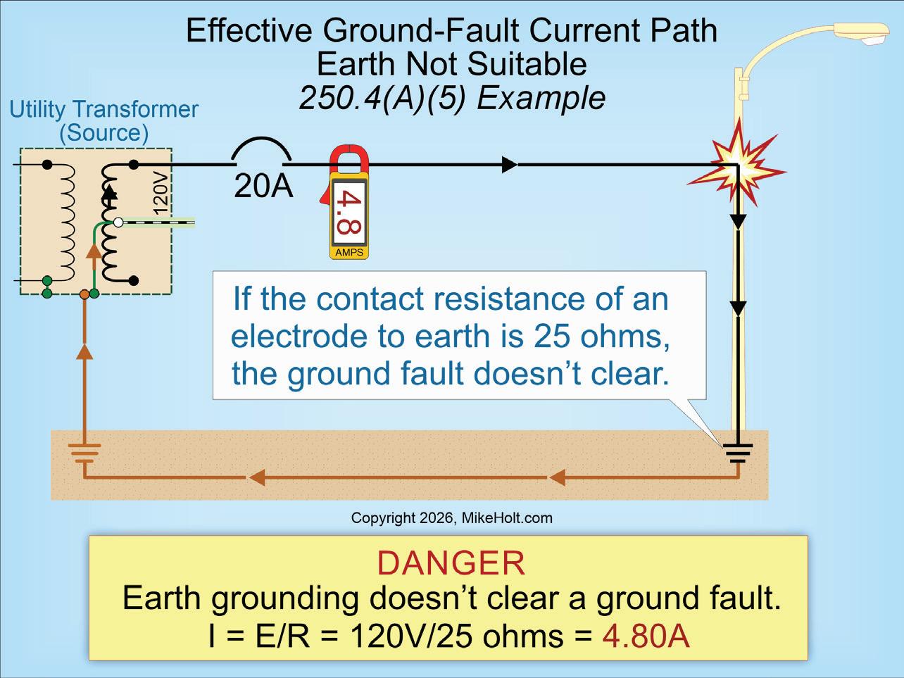
Fig. 2. If the contact resistance of an electrode to earth is 25 ohms, the ground fault doesn't clear.
ground rod, but not bonded to an effective ground-fault current path (Fig. 2)?
(a) 3.70A (b) 4.80A
(c) 5.20A (d) 6.40A
Solution:
I = Volts ÷ Resistance
I = 120V ÷ 25Ω
I = 4.80A
Answer: (b) 4.80A
If you understand earth shells, you will have an easier time applying the requirements for the grounding electrode system and the grounding electrode conductor. You will find these requirements in Art. 250, Part III.
According to ANSI/IEEE 142, Recommended Practice for Grounding of Industrial and Commercial Power Systems (Green Book) [4.1.1], the resistance of the soil outward from a 10-ft ground rod is equal to the sum of the series resistances of the earth shells. The shell nearest the ground rod has the highest resistance, and each shell farther out has progressively larger area and lower resistance.
The earth is an excellent conductor due to an almost limitless number of parallel paths over which electrons can
flow. However, the problem lies in the contact resistance between the grounding electrode and the earth. The surface area of the electrode contacting the earth is minimal compared to the earth itself. Since voltage is directly proportional to resistance (Ohm’s Law), the voltage gradient of the earth around an ener-
The earth is an excellent conductor due to an almost limitless number of parallel paths over which electrons can flow.
gized ground rod (assuming a 120V ground fault) will be as shown in Fig. 3 on page 60.
Remember, the low impedance of the metallic pathway is what makes bonding


This e-newsletter, published four times per month, is dedicated to coverage of the National Electrical Code. The content items are developed by well-known Code experts.
CodeWatch promises to:
• Explain how to properly apply the Code
• Test your knowledge of the Code
• Provide information on upcoming Code-related seminars and shows
• Offer Code quizzes and real-world Code violations
See all of our EC&M e-newsletters at www.ecmweb.com
Since voltage is directly proportional to resistance (Ohm’s Law), the voltage gradient of the earth around an energized ground rod (assuming a 120V ground fault) will be determined using the conversion table above.
work. So you want to keep it low at each connection, and you want to provide parallel bonding paths where practical. The mechanical integrity of the bonding jumper system is also paramount. Selecting the correct connectors for the application and ensuring they are used correctly (e.g., proper torquing values and techniques) are two keys to ensuring low impedance and high mechanical integrity.
As you bond metallic objects together, you are building part of the EGC. Given its construction requirements and its primary function, the EGC serves more the purpose of bonding than grounding. However, it does ultimately connect to the grounding point at the service or separately derived system.
Section 250.118(A) lists 14 types of things you can use as an EGC. Grounding electrode conductors are specifically prohibited for this use [Sec. 250.118(B)]. These 14 types include metallic raceways, cables, and gutters. While you certainly can run a conductor inside a raceway to provide the EGC, the advantage of using the raceway is that its larger surface area takes advantage of the skin effect to provide a better path for high-frequency undesired current.
For high-performance bonding, use both the enclosed conductor
[Sec. 250.118(A)(1)] and the metal raceway. Then look at additional ways to exceed the NEC bonding requirements, for example, by adding bonding jumpers across raceway couplings (as is commonly done in data centers).
To avoid grounding when you should be bonding, remember that you bond if the equipment is on the load side of the service or separately derived source. If a facility is having power quality problems and you spot a motor with a ground rod connection instead of an EGC connection, you have found one cause (perhaps the cause). Follow the requirements of Art. 250, Parts V, VI, and VII to prevent or clear up these kinds of problems.
On the other hand, a service or separately derived source that doesn’t meet the grounding requirements of Art. 250, Parts II and III are going to be vulnerable to high-voltage transients, and so will the connected loads.
These materials are provided by Mike Holt Enterprises in Leesburg, Fla. To view Code training materials offered by this company, visit www.mikeholt.com/code.
By Mike Holt, NEC Consultant
All questions and answers are based on the 2023 NEC.

Q1: Only wiring methods recognized as are included in the Code.
a) expensive
b) efficient
c) suitable
d) cost-effective
Q2: Securing or supporting of LFNC is not required where installed in lengths not exceeding from the last point where the raceway is securely fastened for connections within an accessible ceiling to a luminaire(s) or other equipment.
a) 4 ft
b) 6 ft
c) 8 ft
d) 10 ft
Q3: Metal multioutlet assemblies can extend through (not run within) dry partitions if arrangements are made for removing the cap or cover on all
portions, and no outlet is located within the partitions.
a) exposed
b) concealed
c) uninsulated
d) none of these
Q4: Fuel-dispensing systems shall be provided with one or more clearly identified emergency shutoff devices or electrical disconnects. Such devices or disconnects shall be installed in approved locations but not less than 20 ft or more than from the fueldispensing devices that they serve.
a) 20 ft
b) 40 ft
c) 50 ft
d) 100 ft
Q5: In a 3-wire circuit consisting of two phase conductors and the neutral
conductor of a 4-wire, 3-phase, wyeconnected system, the neutral conductor shall when applying the provisions of Sec. 310.15(C)(1).
a) be counted
b) not be counted
c) be reduced
d) be ignored
Q6: Galvanized steel and stainless steel EMT, elbows, couplings, and fittings can be installed in concrete, in direct contact with the earth, or in areas subject to severe corrosive influences where
a) protected by corrosion protection
b) made of aluminum
c) made of stainless steel
d) listed for wet locations
See the answers to these Code questions online at ecmweb.com/55306126.
Which, if any, of the three conditions specified in Table 110.26(A)(1) apply to this installation?
By Russ LeBlanc, NEC Consultant

When determining the minimum working space depth required between the 480V equipment on the left side of the aisle to the 480V equipment on the right side, which, if any, of the three conditions specified in Table 110.26(A)(1) apply to this installation as shown?
There seems to be some confusion or significantly differing interpretations about this topic. Some Code users say none of the conditions are applicable here, since there are no exposed live parts and Conditions 1, 2, and 3 each include exposed live parts on at least one side of the working space. I understand that interpretation, but that may also be problematic, since it could lead one to believe that no working space depth is required at all here because none of the conditions apply.
I have always explained the working space depth requirements this way. If any of the three conditions specified in Table 110.26(A)(1) could exist at any time during the life of this installation, then those conditions must be applied when determining the minimum space required between equipment. For example, if the covers are removed for servicing or testing of the equipment on the left side, then Condition 2 would be applicable, since there would be exposed live parts on the
left side and grounded parts on the right side. This condition would require a minimum depth of 3 ft-6 in. as measured from the exposed live parts on the left side to the grounded metal enclosure covers on the right side. If covers were simultaneously removed from the equipment on the left side and the equipment on the ride side, then both Conditions 2 and 3 would also exist simultaneously — as there would be exposed live parts and grounded parts on both sides of the working space.
Condition 3 requires a minimum depth of 4 ft as measured between the exposed live parts on each side of the working space. Keep in mind the exposed live parts can sometimes be recessed deep into the enclosure, leading to the potential of having less than 3 ft between the equipment covers if we only measured from live part to live part. That could be a real problem.
Since both Condition 2 and 3 could exist here, the equipment should be installed in a manner that would provide the minimum required spacing between equipment when either condition is applied. Thankfully, there was some Public Input submitted to help clarify these requirements for 2026. As always, I suggest having a discussion with your AHJ to make sure you are both on the same page.


By Russ LeBlanc, NEC Consultant
All references are based on the 2023 edition of the NEC.
I don’t know how it happened, but every clip that was installed to secure this rigid PVC conduit is gone. Only small remnants of each clip remain attached to this pole. Perhaps the clips were not sunlight resistant as required by Sec. 300.6(C)(1) and disintegrated from long term exposure to the sun. Unfortunately, I have seen that happen in several installations.
Table 352.30(B) requires 3/4-in. rigid PVC conduit to be supported at intervals no greater than 3 ft. This conduit run may have complied with that requirement when it was originally installed, but it most certainly does not comply now — leading to a big bow in the conduit. On a more positive note, the installer did include an expansion coupling in the PVC conduit run as required by Sec. 352.44(A).
One other problem I spotted with this installation was the lack of a cover for the receptacle installed in the box near the bottom of the pole. Section 406.9(B)(1) requires 15A and 20A, 125V and 250V receptacles to be installed in enclosures that are weatherproof whether or not an attachment plug cap is plugged in. This enclosure is wide open to wind, rain, snow, and all the elements Mother Nature can throw at it.


This liquidtight flexible nonmetallic conduit (LFNC) has pulled out of the connector, leaving the conductors exposed to sun, rain, and all kinds of other potentially damaging forces. The separated conduit can also allow water to enter directly into the raceway. In winter, this water could freeze, expand, and cause severe damage to the raceway, potentially splitting it open. Section 356.30 provides several different requirements for securing and supporting LFNC. This installation complies with none of them. Section 300.11(A) requires raceways to be securely fastened in place.
Section 300.12 requires raceways to be continuous between boxes, conduit bodies, other enclosures, fittings, and outlets. This installation violates this requirement. Section 310.10(D) requires conductors exposed to direct sunlight to be listed as being sunlight resistant or be covered with an insulating sleeve or tape that is listed as being sunlight resistant. The THWN-2 conductors used here are rated for use in wet locations, but its insulation is not sunlight resistant. If not repaired, the insulation will eventually break down. On a positive note, the “bubble cover” installed on the switch box provides a weatherproof enclosure as required by Sec. 404.4(A).
To place a display ad (1/6 page or larger), call the Advertising Sales Representative for your area.
Vice President
Mike Hellmann
Andover, MA • (978) 289-0098
E-mail: mhellmann@endeavorb2b.com
Western U.S. & Western Canada
Ellyn Fishman | Key Account Manager (949) 239-6030
Email: efishman@endeavorb2b.com
Northeast U.S. & Eastern Canada
David Sevin | Account Manager 24 Houghton Street • Barrington, RI 02806 (401) 246-1903
E-mail: dsevin@endeavorb2b.com
Midwest, Southeast,and Southwest
Jay Thompson | Account Manager 7450 W. 130th Street, Suite #210
Overland Park, KS 66213 • (913) 967-7543
E-mail: jthompson@endeavorb2b.com
Marketplace/Inside Sales
Steve Suarez | Media Account Exec 7450 W. 130th Street, Suite #210
Overland Park, KS 66213 • (816) 588-7372
E-mail: ssuarez@endeavorb2b.com


By Russ LeBlanc, NEC Consultant
How well do you know the Code? Think you can spot violations the original installer either ignored or couldn’t identify? Here’s your chance to moonlight as an electrical inspector and second-guess someone else’s work from the safety of your living room or office. Can you identify the specific Code violation(s) in this photo? Note: Submitted comments must include specific references from the 2023 NEC.
Hint: A wobbly weatherhead
Using the 2023 NEC, correctly identify the Code violation(s) in this month’s photo — in 200 words or less — and you could win a $25 Amazon gift card. E-mail your response, including your name and mailing address, to russ@russleblanc.net, and Russ will select one winner (excluding manufacturers and prior winners) at random from the correct submissions. Note that submissions without an address will not be eligible to win.


Unfortunately, I received no winning submissions citing the violations in this photo. When splicing conductors of NM cables and other cables, Sec. 300.15 provides requirements for when a box, conduit body, or other enclosure is required. Where the wiring method is conduit, tubing, AC cable, MC cable, MI cable, NM cable, or other cables, “a box or conduit body shall be installed at each outlet point, switch point, conductor splice point, conductor junction point, conductor termination point, wiring method transition point, or conductor pull point, unless otherwise permitted in 300.15(A) through (L).” None of the provisions in (A) through (L) apply to this installation. This means those splices must be installed in either a box or a conduit body.
For temporary wiring, Sec. 590.4(G) Exception 1 allows splices on construction sites to be made without being installed in a box or conduit body. The wiring shown in this photo, however, was not temporary — it was permanent wiring installed in the basement of a home. Therefore, Art. 590 does not apply to this installation.


No burn-through eliminates elbow repairs
Light weight facilitates a smooth, safe installation


Fault resistance makes repairing cables easy
Durable and corrosion-resistant for lower total cost of ownership
