


Stronger in numbers. Add yourself to the equation. Miguel isn’t one to ask for help. Equipped with The TRITON™, which provides verified fixes harvested from users across the globe, he doesn’t have to. Offering a 2-channel lab scope and wireless connection, it’s like having 70 thousand techs, each with 40 years of experience at his side. So you can cover Miguel’s back, and he’ll cover yours. Plus up your numbers with the diagnostics system that adds you to the equation.


•The most trusted name in aftermarket window regulators, with industry-leading coverage for over 95% of vehicles in operation

•Dorman pioneered aftermarket window regulators and continues to develop, design and deliver thousands of road-proven solutions today


•Reduces repair time by up to 75%


•One part, one fast fix and one visit, all from the one market leader


•3600+ drive shafts and counting

•Pre-pressed, bolt-on assemblies change the game by slashing repair time, simplifying scheduling, freeing up equipment and delighting customers

•The highest quality end-to-end, the fastest delivery coast-to-coast
•Thousands of direct replacement light duty drive shafts and coverage for many failure-prone medium and heavy duty shafts, shipped where you need them, when you need them


04 Online Extras
06 Straight Talk 08 Tech Tips
TECHNICAL
10 Diagnostic Debriefing:
Keeping a Diagnostic Journal
Mistakes and missteps in diagnostics are par for the course. But if you’re not documenting and learning from them, they’re simply a wasted chance at improvement.
Brandon Steckler
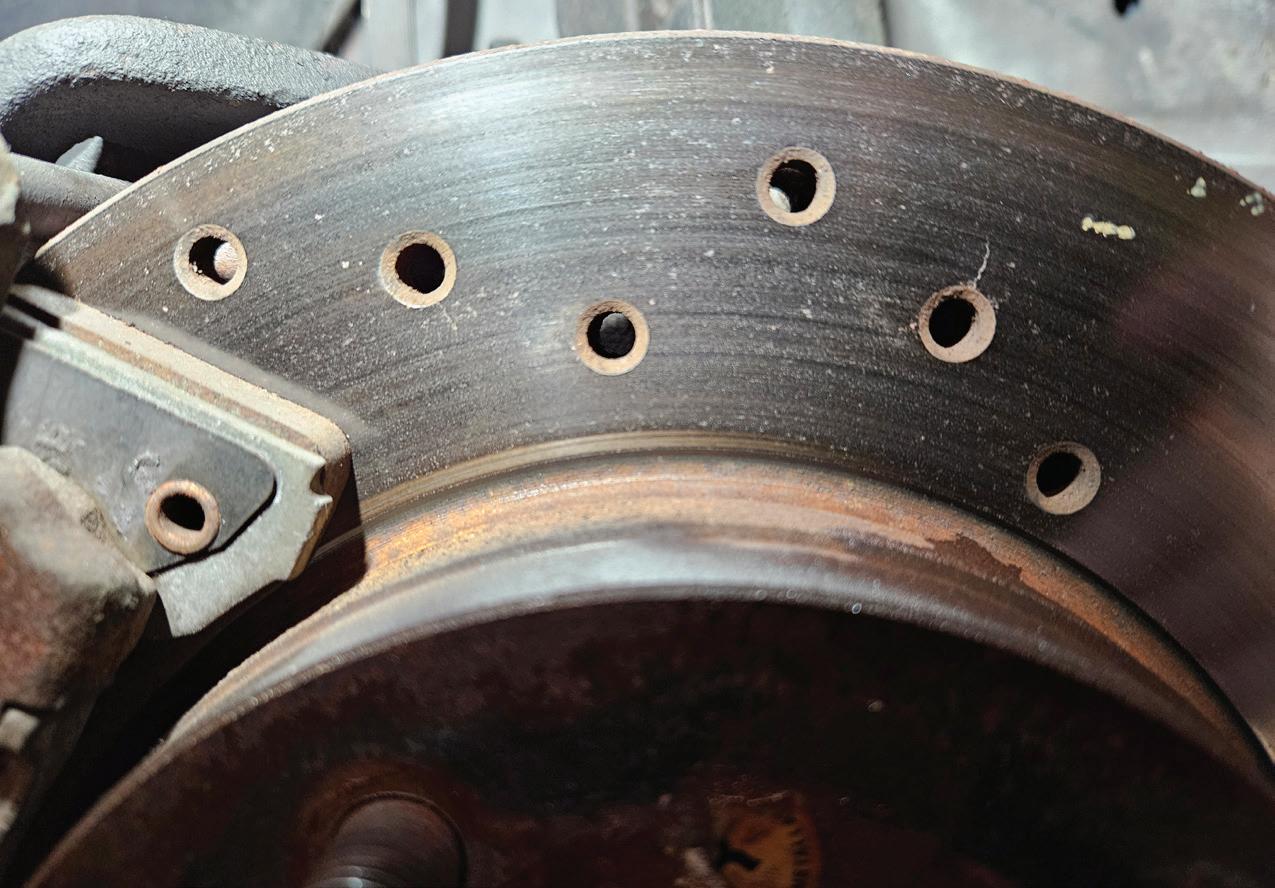
19 Modern Brake Rotor Design
An often overlooked partner in the braking system, the rotor’s design and makeup matter.
Erik Screeden
26 Catalytic Converter Care & Diagnosis
Evidence of a ‘failed’ converter may be due to other factors
Mike Mavrigian
34 Diesel Particulate Filters
A comprehensive guide to function, failure, and maintenance
Jeff Taylor
43 Come Get Your Fill
Cylinder integrity is more than just the ability to harness and squeeze its contents. The fact is, if it can’t fill, there will be little compression.
Brandon Steckler
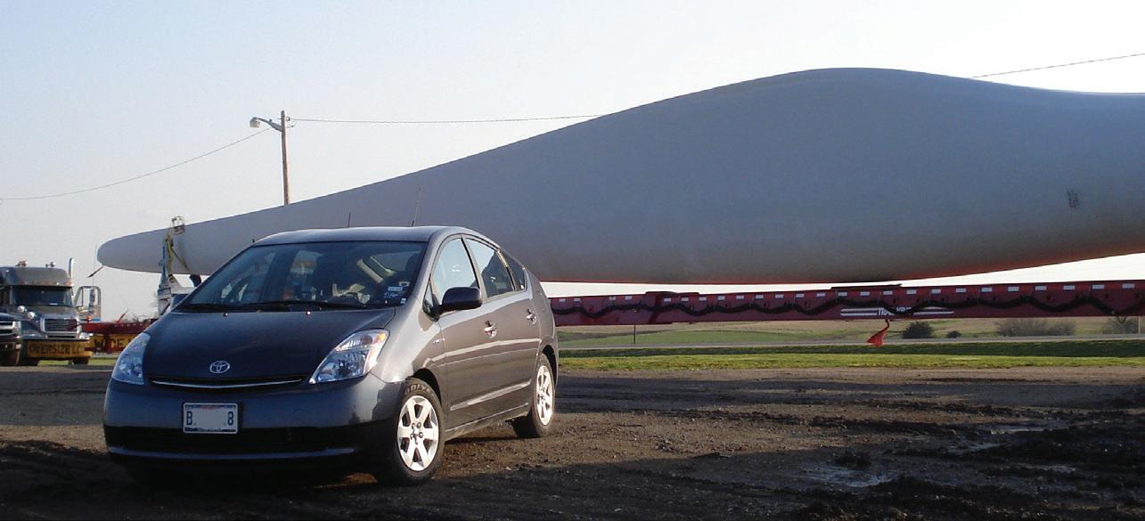
48 The Greening of the Grid
How do EVs fit in rural America?
Craig Van Batenburg
66 The Trainer #161
System and Component Performance Evaluation: Solenoids
Brandon Steckler
EDITORIAL
GROUP EDITORIAL DIRECTOR
Chris Jones / christopherj@endeavorb2b.com
EDITOR
Mike Mavrigian / mmavrigian@endeavorb2b.com
MANAGING EDITOR
Joy Kopcha / jkopcha@endeavorb2b.com
TECHNICAL AND MULTIMEDIA CONTENT DIRECTOR
Erik Screeden / escreeden@endeavorb2b.com
TECHNICAL EDITOR
Brandon Steckler / bsteckler@endeavorb2b.com
ASSOCIATE EDITOR
Madison Gehring / mgehring@endeavorb2b.com
CONTRIBUTING WRITERS
Jeff Taylor, Craig Van Batenburg
ART AND PRODUCTION
ART DIRECTOR

We know many Motor Age readers are faithful followers of Technical Editor Brandon Steckler’s diagnostic work, including his monthly Data Doesn’t Lie puzzles that appear in each issue of the magazine. Those columns also appear monthly on VehicleServicePros.com, and new in 2025 we’ve added an interactive element. At the bottom of each case study, you can weigh in on which option you’d choose to solve the diagnostic puzzle — and see how other technicians voted. Look for Brandon’s articles online!

FIND BRANDON STECKLER’S WORK ONLINE!
Members of the Motor Age team were on the ground at the 2025 NAPA NOW event in Las Vegas in April, and the team shared a glimpse of the new initiatives underway, including the relaunch of Carlyle Tools. NAPA senior product specialist Joseph Sabo outlined the brand’s bold colors as one way it wants to make an impression on Gen Z technicians.
Emme Osmonson
PRODUCTION MANAGER
Mariah Straub
AD SERVICES MANAGER
Karen Runion
SALES
ASSOCIATE SALES DIRECTOR
Mattie Gorman-Greuel / mgorman@endeavorb2b.com
DIRECTOR OF BUSINESS DEVELOPMENT
Cortni Jones / cjones@endeavorb2b.com
ACCOUNT EXECUTIVES
Kyle Shaw / kshaw@endeavorb2b.com
Marianne Dyal / mdyal@endeavorb2b.com
Annette Planey / aplaney@endeavorb2b.com
Darrell Bruggink / dbruggink@endeavorb2b.com
Sean Thornton / sthornton@endeavorb2b.com
Diane Braden / dbraden@endeavorb2b.com
Lisa Mend / lmend@endeavorb2b.com
Chad Hjellming / chjellming@endeavorb2b.com
ENDEAVOR BUSINESS MEDIA, LLC
CEO
Chris Ferrell
COO
Patrick Rains
CRO
Paul Andrews
CDO
Jacquie Niemiec
CALO
Tracy Kane
CMO
Amanda Landsaw
EVP VEHICLE SERVICE/REPAIR GROUP
AND FLEET AND TRAILER GROUP
Chris Messer
BUSINESS STAFF
PUBLISHER
Andrew Johnson
BUSINESS DEVELOPMENT DIRECTOR, MOTOR AGE TRAINING
Michael Willins
CUSTOMER MARKETING MANAGER
Leslie Brown
AUDIENCE DEVELOPMENT MANAGER
Tracy Skallman
SALES COORDINATOR
Jillene Williams
HOW TO REACH US
ENDEAVOR BUSINESS MEDIA LLC.
30 Burton Hills Blvd, Ste. 185, Nashville, TN 37215
Phone: 800-547-7377
CUSTOMER SERVICE
Subscription Customer Service 877-382-9187; 847-559-7598
MotorAge@omeda.com PO Box 3257 Northbrook, IL 60065-3257
REPRINT SERVICES reprints@endeavorb2b.com
MEMBER OF:


REGARDLESS OF HOW SUCCESSFUL your shop may be at the moment, new, fresh promotional programs are always a good idea, both to attract new customers and to reinforce your relationship with existing customers. There’s no such thing as too much good press.
According to recent data, about 65 million American households own at least one dog, and about 46 million households own at least one cat. Numbers vary state-by-state, but you get the picture. A mind-boggling number of current and potential customers maintain pets as part of their families.
Consider creating a “pet friendly” promotion, perhaps once each year or more. To minimize any potential conflicts among cats and dogs gathered in one location, an option might be to establish a “dog day” and a “cat day” on separate dates.
Tips for conducting an event:
• All pets must be on a leash (a safety concern).
• Make snacks and water available (Food items should be of the dry type to avoid spoilage. For example, Milk-Bones for dogs and dry kibble for cats).
• Outdoor areas should include tents or awnings for shelter from rain or sun.
• Enlist a local animal shelter for volunteer assistance in running the event.
• Consider arranging for a local animal shelter to bring animals for adoption, or consider animal rescue and pet adoption as the event theme.
• Plan the event at least six months ahead of time and promote the event by means of flyers and local media advertising.
• Be sure to invite and get commitments
from local media (newspaper, TV, radio) to cover the event.
• Speak to your insurance carrier for advice on conducting the one-day event and to obtain an insurance rider, if necessary.
• Limit the physical event to your parking lot. Avoid allowing customers and pets into the service bays, for safety concerns.
• If your place of business is limited in terms of available space for the event, consider holding the event at a local park. In either case, have banners and signage on display to feature the shop name and address. Speak to your local town/city government both to gain written permission and to reserve a date for the event.
• Consider having matching shirts made that feature your shop name/logo, to be worn by all employees and outside volunteers that are involved in hosting the event.
• As part of the event, announce (in all promotional material) that the shop will make a donation to one or more local animal shelters. This could be a specific amount, or a percentage of shop income for a day, week, etc.
• Consider offering door prizes in the form of a drawing, for cutest puppy, etc. This might involve a free oil change, tire check, and rotation, etc.
• As part of the event, if sufficient space is available, consider creating a free vehicle inspection lane, where your technicians perform a routine vehicle inspection. This can include checking tire tread and inflation, tire wear, wipers, engine oil level, DTC scan, etc. Techs should have a pre-printed inspection sheet that
marks areas that are good as well as recommendations for needed service. Offer this as a complimentary service, and list needed service only, leaving it up to the vehicle owner regarding where that service should be provided. Do not push the owner to have any service done by your shop specifically. The event itself will lean the vehicle owner to patronize your business.
People who consider their pets as a member of the family — which is the majority of pet owners, by the way — tend to support a business that is pet-friendly and that shares pet owners’ concern for animal welfare. Assuming, of course, that the shop offers quality service and has a reputation for great customer service, setting aside a special day for customers and their pets can go a long way in gaining new and current customer trust and loyalty.


MIKE MAVRIGIAN MOTOR AGE // EDITOR mmavrigian@endeavorb2b.com


Our 10AP Series offers the convenience of wide or narrow installation wrapped up into one configurable package. This durable, safe, and reliable car lift features an expandable top beam and BI-METRIC™ arms to suit virtually every vehicle lifting requirement – symmetric or asymmetric. The 2-in-1 design gives operators the option of loading vehicles either symmetrically (centerline of vehicle at column) or asymmetrically (centerline of vehicle behind column). The simple, yet highly sophisticated design is sure to keep operating costs low and productivity high. Check out the full line of 10AP lift series at bendpak.com or call us at 1-800-253-2363
If you determine that a rattle noise is found at the right front of a 2018-2020 Nissan Armada, check the clearance between the heat shield above the front right-hand tube and the frame. Clearance should be at least 10mm. The clearance between the rear cooler and heater pipe and the heat shield (above the exhaust front tube) should be at least 6mm.
Some 2015-2020 Ford F-150 (except Raptor), 2017-2020 F-Super Duty, and 2018-2020 Expedition vehicles equipped with a front camera washer may exhibit a fluid leak at the front camera washer jet when not in use. This is likely caused by a worn or damaged internal rubber seal in the jet washer. If the unit leaks, replace the washer with P/N HC3Z-17603-B.


Mercedes-Benz strongly recommends cleaning any corrosion and scaling on the hubs when performing brake service. Use the ATE Teves Hub Cleaning Kit to remove corrosion/scaling over the entire area where the brake disc mounts to the hub flange. Failure to do so may cause an excessive buildup which can create adverse forces that may result in brake vibration/judder.


If you’re servicing a 2021-2022 Tesla Model S Palladium or Model X Palladium, be sure to check the fluid level in the Plaid Rear Drive Unit (RDU) gearbox. Due to a faulty gauge used in the factory fluid filling process, the volume may be less than 2.5 liters. When checking fluid, if metallic particles are found, replace the RDU (P/N 176200000-D). If OK, fill to specification.

When performing service on a 20142019 Chevy Corvette, you may find DTC B1517 set in one or more modules. First check the battery cable connections. The small black wire that connects to the larger battery negative cable may be loose or damaged. When reviewing the vehicle’s past history, you may find that the battery was recently replaced and the small black wire may have been neglected or damaged. Any loose connection or damage to this circuit can cause a B1517.


Mistakes and missteps in diagnostics are par for the course. But if you’re not documenting and learning from them, they’re simply a wasted chance at improvement.
BY BRANDON STECKLER


ALL EXPERIENCED DRIVEABILITY and diagnostic technicians have seen their fair share of mistakes. It’s all part of the learning process. In fact, in my opinion — if you are not making mistakes, you aren’t pushing yourself to step outside of your comfort zone and learn something new.
The difference between myself and some of my peers that I grew up alongside of in this industry is that I leveraged my mistakes as an opportunity to improve. This came in the form of brutally honest personal reflection and thorough documentation of the entire experience (Figure 1) — not only in what I found wrong with the vehicle, but the steps I took to get there. Some of them were wise, many were not. But the fact is I learned, and so can you. Check out the method to my madness.
The Innocence of Youth
I’ll begin with my very first mobile diagnostic job in the winter months of 2008. I had just begun working outside of the OE environment of the dealership and was broadening my horizons. Some may say I was crazy for doing that because I was doing well at the dealership (and not yet well on other makes and models). But I was bored and needed more. It was rarely easy but I’m so glad I made that change.
I was faced with a phone call from my (now) good buddy, John. He owned a transmission specialty shop just outside of Philadelphia. John is a very capable technician but simply lacked the time to involve himself with troublesome diagnostic challenges outside his realm of transmissions.
John told me he had in his possession a 1988 supercharged Ford Thunderbird with the complaint of an intermittent stall. John then asked if I was willing to come down and look at the issue for him (I sure as heck wasn’t going to say “no.”)
I made the 75-mile drive and was faced with the Thunderbird. It started without hesitation and with no warning lamps illuminated so I proceeded to drive the vehicle for well over an hour before it
stalled for me. Full of excitement (but also anxiety, as I was on the side of the road more than 5 miles from the comfort of the shop, and supervision), I turned the key and expected some signs of trouble. However, to my surprise, the engine fired up without hesitation and I continued my drive. This time, I drove six hours without even a sign of stalling in sight. The end of the day was near and I made my way back to the shop with my tail between my legs. Thoughts ran through my head:
• How will I explain eight hours of invested time to John — and without a resolution?
• How can I expect to get paid for my time if I hadn’t accomplished anything?
• Am I paying to fill the tank of this gas-guzzler?
• Will John send me packing or worse — will he expect me to stay the course? All of these questions made me uncomfortable and for the first time, I felt unsure of myself and my future as a diagnostician. To my surprise, John was not upset when I told him. He, in fact, wanted me to keep trying. “Next weekend it will be here for you, Brandon” is the last thing he said to me that day. The real kicker is, when I moved the vehicle into the shop for security purposes, it stalled on me. (And yes, I was almost in tears as it was now closing time.)
The following Saturday I made another 150-mile round trip to take another stab at the elusive fault — this time with a fresh attitude and confidence. I drove the vehicle for two hours before it stalled. Although I was timid and already frustrated, I kept at it. I was only a block from the shop so I started the engine, and beat-feet back to the shop.
Once there I decided to capture fuel pump current. (Why? It was a test I learned to do from Jim Linder and it looked cool.) The results showed a flawlessly operating DC motor (Figure 2). It didn’t bring me any closer to fixing the car but at least I proved something was not broken or suspect.
I was at a loss. I wasn’t sure where to go from here and I was too embarrassed to ask for input. At this point at least no one knew I was clueless. I figured I’d just fake it until I made it.
The day came and went and I was nearing the second weekend (nearly 16 hours invested) and nothing to show for it except for another empty gas tank and a flawless fuel pump current ramp capture. It was at that point I pulled the car back in the shop at closing-time.
As I did, it stalled again! Now, I was getting excited because both times the car entered the shop, the stall occurred. Could this be a clue?
John witnessed my conviction and excitement and agreed to stay late while I attempted to throw a net over this Thunderbird. What I noticed about the stall is that it occurred only in a specific work bay (the alignment bay, with the ramps). As I hit the base of the ramps the stall occurred. I decided to take the vehicle on the road and retrace my steps to repeat the
road test, specifically where I remember the stall occurring. Each time the stall occurred I noticed there was a nasty pothole present. I decided to deliberately aim for the speed bump in a nearby parking lot and, as if I knew what I was doing, I was able to repeat the stall, seemingly at will. I returned to the shop and opened the hood with the intention of testing circuits related to the ignition coil control module (like the ignition coil, the CKP sensor, CMP sensor, etc.). I figured if it was a fueling issue, it wouldn’t have stalled as suddenly and certainly wouldn’t have restarted flawlessly. Now, I was getting somewhere.
As I prepared to infiltrate the circuits, something at the ignition control module caught my eye. It was a poorly fitted cable tie used to mate the wire harness to the ignition control module. The connector assurance tab was broken (Figure 3). I thought there was no way it could be this obvious. I touched the connector and the engine stalled. I chanted with excitement!
With great pride I expressed my hard work and diligence to John. I demonstrated the fault for him and he compensated me


for my time. He said he would have his tech splice in a new connector and assured me he would be calling me next time he needed my services.
With a huge smile on my face, I still faced a 90-minute ride home but it gave me time to reflect on my 16-hour saga. I was proud of myself for sticking it out and not quitting but now it was time to face the fact that it was ugly.
I needed to make some changes but what, and how? What could I have done differently to make this job go smoother? It wasn’t my fault the car took eight hours to stall, and I couldn’t change the fact the car yielded very little diagnostic data to be ascertained from a scan tool.
I’m sure you realize I’m jokingly and deliberately making poor excuses that we’ve all heard, or maybe even said. I realized there had to be a better way, but the only way I would be able to discover that was to take responsibility for my actions and my lack of structured diagnostic approach. I would wait to get home because I had ideas I needed to get on paper.
As I sat at my dining room table and placed my ideas down on paper, it all came out in paragraph format, like a journal entry. Things like “If I didn’t see this through visual inspection, how could I


have tested for it?” With the tools I had at that time, there certainly wasn’t a test that would show the fault — and the results would have pointed to a faulty ignition control module as the signal would have always remained present on the suspect circuit(s).
Obviously, replacing the module would have been a bad mistake. But, with the flawless signals (and 20/20 hindsight vision) logic would now have me inspect the connector integrity before condemning the ICM. Why? Because we can’t test inside the connector, we can only eliminate everything else (Figure 4).
This journal entry also included some bullet points describing what data I took note of and the description of the experience overall. It was only after I had read what I wrote that I realized this would be my secret weapon in powerful diagnostics.
The journal entry showed all the holes in my approach, and also told me what I should do differently if I was presented this same opportunity again.
With that, I realized if I had asked just a few questions ahead of time, I would most certainly have saved myself about 15 hours of time. These could have been
questions to ask the shop owner, or better yet, the client.
• Where were you driving when the car last stalled?
• Have you ever been able to reproduce the stall on the same road?
• When the stall occurs, is it typically on bumpy roads?
• Do weather conditions play a role?
• When did this problem start?
Those are just a few ideas that come to mind. And to be honest, when I later spoke with the customer he indeed indicated — but only when asked — that the stall occurred mostly on rough roads. If I had asked that question up front, I could have cut down my time spent on the road test and then followed it up with a thorough visual inspection.
But preceding both the road test and


BY THE AUTHOR


BY


the visual inspection another question had crossed my mind. I should have asked the customer if there was any recent work performed on the vehicle, and if so, did the fault surface after that work was performed? The answer to both of those questions would have led me to the next — What work was performed? (Or, can I see the invoice?)
The customer would have told me that an engine transplant was performed. I realize now, through experience, that some of the most difficult issues to find are man-made ones. A thorough visual inspection would have brought me directly to the culprit in no time at all.
So, how did this alter the way I approach driveability issues? I begin my approach to any issue as an opportunity to gather valuable information pertaining to the nature of the symptom/concern. As you’ve seen in my previous articles, a customer interrogation is crucial. I learned this from my mentor, Jim Morton. He led by example as he solved an average of 28 driveability symptoms per day. That type of proof cannot be argued with.
Performing basic tests and document-
ing the results yields a lot of overall generic information about the vehicle and puts a lot to rest early in the process — things like the functionality of the battery and charging system. Being the heart of the entire vehicle, I wouldn’t expect anything to function properly without this system in proper working order. These take a few moments to do and then they can be forgotten about for the duration of the analysis after their functionality is proven to be satisfactory.
Scanning for DTCs vehicle-wide is highly recommended. Seemingly unrelated system faults could in fact be the root cause of the symptoms exhibited — such as an ADAS or 4x4 system fault due to a wheel speed sensor circuit issue. Writing down the DTCs with the order of the approach you have chosen (and why you chose that order) gives you something to reflect on later.
Writing down the component tests performed and where (in the circuit) the data was obtained is another strong lesson I’ve learned. For instance, testing at a ground-side driven component (like a port fuel injector) at the ECU is basically looking to see if the voltage has not pulled all the way, or close to, ground (Figure 5).

That is an expected outcome for a healthy circuit, as an elevated voltage would indicate a poor path to ground. However, if a fault was present closer to the fuel injector it wouldn’t be detected. It’s for this reason I test as close to the load device as possible (Figure 6).
But regarding inputs, I test as close to the ECU as possible. When you take the time to think about it, it’s easy to imagine a sensor functioning correctly but a broken wire or loose connector terminal preventing that healthy signal from being seen by the ECU. How do you think I learned this logic? That’s right, by getting my rear-end handed to me. But because I took the time to journal, I’ve been able to learn from my mistakes and polish my approach.
Techniques like the ones described above are lessons that are difficult to teach. But believe me when I tell you they are not hard to learn. Slow down, document and revisit the entire job when it’s complete.
Be your own biggest fan but be critical about your approach. Learning firsthand what is working, what is not working, and what can simply be streamlined is invaluable and will serve you well for the rest of your career!


An often overlooked partner in the braking system, the rotor’s design and makeup matter.
BY ERIK SCREEDEN
TECHNICIANS CAN’T GO to any sort of training event without being inundated with instruction and information on ADAS.
From blind spot monitoring, lane departure warning, and lane-keep assistance (LKA) to adaptive cruise control (ACC), automatic emergency braking (AEB) and cross traffic alert, all these systems work in concert with one another to keep drivers
and their passengers safe. And while all these systems are important for a technician to understand, these advanced driver assistance systems only work as well as the base vehicle system they work with. This means lane-keep assistance won’t keep you in the lane if the tie rod ends and ball joints are worn out, and vehicle stability control is unable to correct for a skid as effectively if the wheel speed input it’s getting from
one of the corners is not accurate. These systems must work in unison, at the same efficiency as designed by the engineers, to keep us safe during intervention events. At the top of the list for these systems to operate at peak performance is the base brake system.
Brake Rotor Function and Heat Dissipation
When it comes to the brake system, most agree the focus is generally on brake pads. Brake pad material makeup and design, friction coefficient, and even the
shape of the puck, are all important factors on how well a brake system will perform, both in terms of stopping efficiency as well as noise. But the often-overlooked partner in the brake system is the brake rotor itself. Rotor design plays as crucial a role in brake system performance as the brake pad, and it’s an important relationship for technicians to understand to make sure they’re selecting a rotor that can match the performance of the brake pad and help with the needed outgassing and heat dissipation. The brake rotor’s main function is to convert kinetic energy into heat through friction. As the brake pads are applied to the rotor, that friction generates tremendous amounts of heat, and the rotor material makeup, as well as its ability to dissipate that heat, greatly affects brake system performance.
Rotor design has evolved, just like everything else in the automotive indus-
try. Starting out in the early days of disc brake systems as mainly cast iron units with integrated hubs, they have evolved into a variety of designs using a range of materials to provide heat dissipation. The design also takes into consideration the drive to reduce unsprung weight to improve fuel efficiency and braking performance. But with that weight savings can come the trade-off of reduced durability and increased noise, vibration, and harshness. Cast iron does a wonderful job in heat dissipation but adds significant weight and is prone to corrosion. Carbon ceramic rotors can have longer service lives but are costly. There is a give and take and that balancing act is taken into consideration when the vehicle and braking system are being designed at the factory. It’s something to keep in mind when servicing these systems, especially when servicing a vehicle with vehicle stability control and ADAS technologies.

As the four-wheel drum brake system transitioned into the early front disc rear drum braking systems around the midpoint of the last century, auto manufacturers still used a relatively similar cast iron metallurgy as many of the previous drum brake designs. Cast iron brake rotors offer many advantages. Cast iron has a high thermal mass meaning it can absorb significant amounts of heat without seeing a degradation of performance, which helps maintain consistent braking performance under more typical driving conditions. Cast iron is also relatively cost effective, especially when compared against materials like the aforementioned carbon ceramics. It’s also readily available for both the OE and the aftermarket. Manufacturing is also well established, which helps keep those production costs down. While cast iron has many advantages, it has limitations as well. Factors like increasing vehicle unsprung weight negatively affect vehicle performance, and economy. Cast iron is also prone to oxidation and rust, though some modern coatings like zinc and ceramic, or high-carbon alloys, can help to improve their corrosion resistance. Cast iron also absorbs heat very well, but even with ventilation it does not dissipate that heat as well as some of the composite options available. It’s the heat buildup under very heavy braking events that can lead to rotor failures like cracking over time. Cast iron gives consistent braking performance that’s crucial for systems like automatic emergency braking and adaptive cruise control, but the added weight and high heat retention can make other designs more desirable in certain applications.
On the other end of the spectrum are carbon ceramic brake rotors. These rotors are used in ultra luxury and high-performance/super car applications like the C7 and C8 ZR1 Corvette, McLaren P1, various Porsche models and the Mercedes-AMG GT
Black Series. These rotors are constructed from a carbon-fiber reinforced silicon carbide composite. This offers exceptional heat resistance, weight reduction, and longevity compared to traditional cast iron rotors. These rotors can withstand temperatures of over 1,000 degrees Fahrenheit without losing braking effectiveness, but they can shed that heat fairly quickly and that reduction of heat buildup also minimizes brake fade, helping to ensure consistent stopping power. While light braking before the brakes have a chance to warm up can be less effective compared to cast iron rotors, the main downside to carbon ceramic is the cost. These rotors can often cost thousands of dollars per set, which really limits their widespread adaptation beyond the ultra-high end.
With both ends of the spectrum covered between the jack-of-all-trades cast iron on one end and the ultra-premium carbon ceramic on the other, engineers have sought to find some middle ground. Composite rotors give us that flexibility. Composite or hybrid brake rotors combine different materials, like cast iron and aluminum, to optimize weight, heat dissipation, durability, and cost. These designs improve braking efficiency, reduce unsprung weight, and enhance overall vehicle handling. Some of the key benefits of composite rotors are they reduce weight without sacrificing strength. They do this using a two-piece design, running a lightweight material on the hat like aluminum — this reduces overall weight compared to full cast iron rotors. This less unsprung weight improves handling, acceleration, fuel efficiency, and even has a positive impact by reducing strain on suspension components, improving vehicle dynamics. The aluminum center also helps disperse heat more efficiently, and floating or semi-floating designs allow for thermal expansion, which minimizes stress cracking. ADAS features like AEB and ACC require predictable and fade-resistant braking perfor-
mance, and composite rotors ensure that consistent braking force, which improves the accuracy of ADAS-controlled stops. While composite brake rotors are significantly cheaper than options like carbon ceramic, they still are generally a higher price point than a traditional cast iron option. Also, some of the lesser expensive aftermarket composite rotor designs have been prone to suffering from hat-to-ring separation under extreme conditions.
There is far more to rotor design than the
material from which they are manufactured. Many of their performance characteristics come from their design features as well, with the goal of converting that kinetic energy to heat through friction. And to dissipate that heat, we need airflow. The primary way this is accomplished is through internal cooling vanes or channels between the two braking surfaces. It’s the goal of these vanes to simply increase the airflow to improve heat dissipation and reduce fade. These vanes work well, as long as they can stay clear enough to perform their intended function. In heavy


rust-prone areas, there is a tendency for rust and road debris to clog those vanes, prohibiting needed airflow and throwing the brake rotor off balance. Some manufacturers have moved away from the traditional vane design and have incorporated pillars and other designs to improve airflow further and lessen the chances of some of these clogging events. Also, though becoming more rare, some lighter vehicle applications still use a solid rotor, especially in the rear. Solid rotor designs can provide a lightweight option where weight savings are crucial, and they are more resistant to debris. Since they are less likely to trap dirt, they are ideal for off-road applications.
When it comes to braking performance, heat dissipation is a necessity, and metallurgy and design play critical roles in
high performing and consistent braking. However, there are other forces at work that need consideration for optimal performance. We have established that heat is a trade off of the braking process, and the more aggressively the brakes are applied, the higher the heat that is generated. During heavy braking, brake pads release gas as they heat up in a process called “outgassing.” The amount of gas varies by pad makeup, but the result is a thin layer of gas that acts as a buffer between the pad and the rotor. This can dramatically affect how much contact the brake pads make with the rotor, and thus affect the ability of the brakes to slow the vehicle.
Under normal daily driving conditions, outgassing does not occur at a rate that drastically impedes braking function. But in applications where continuous high heat levels are expected, there comes the need to allow that built up layer of gas to
escape from between the pad and rotor. To facilitate this, rotor manufacturers have implemented technologies like slotting and cross drilling to allow the gas layer to dissipate. While a cross drilled rotor allows for the removal of gas buildup and additional cooling due to more airflow, this comes at a cost — the structural integrity of the rotor. Cross drilled rotors are susceptible to cracking between drill points after prolonged heavy use. Slotted rotors are stronger structurally than a cross drilled design because of the fewer stress points, but they can accelerate brake wear as the slot edges can act like a file, wearing pads quicker than a smooth or drilled rotor design.
The lion’s share of brake rotors in use today on passenger vehicles are still


the tried-and-true cast iron design, and as we stated earlier, one of the largest drawbacks to these rotors is oxidation and corrosion. Corrosion not only adversely affects braking performance and rotor life, but it also negatively affects the vehicle’s aesthetics. The trend in modern vehicle design is to have a larger, more open wheel, and a rusty brake rotor takes away from that look.
It’s for these reasons that many brake rotor manufacturers have started providing corrosion-resistant coatings for their rotors to keep them corrosion-free longer in even some of the harshest environments. Manufacturers use a variety of coating materials to accomplish this goal, depending on rotor makeup and overall price point. One of the more common coatings used is a zinc coating. Zinc coating is applied to a brake rotor via electroplating, or dipping, and it forms a barrier

THEIMAGEENGINE / ISTOCK / GETTY IMAGES PLUS


against moisture and road salt. Zinc provides sacrificial protection, meaning it will corrode before the iron does. Zinc is cost effective and widely used, helping to protect against premature wear and compromised structural integrity. The drawback: it’s a relatively thin layer of protection, and because of its sacrificial properties, it tends to disappear quickly in extreme conditions.
Ceramic coating is another option used by rotor manufacturers to protect the brake rotor. Like zinc, ceramic coatings are resistant to rust and corrosion, but unlike zinc, ceramic is more resistant to extreme heat, making it well suited for performance and premium applications. The tradeoff with ceramic coatings is it’s significantly more expensive than zinc, and it is more labor intensive to apply to ensure even coating and protection.
Phosphate coating, or what is also known as “e-coating” is a chemical coating where the iron rotor is submerged in a phosphate-based solution, then a liquid paint solution is applied and electrically charged — causing the coating particles to bond evenly to the metal surface. This,
paired with a curing process, ensures durability and longevity of the coating on the non-friction surfaces. Common with many OE and aftermarket replacement rotors, e-coating provides a more durable barrier than zinc but at a more competitive price point than ceramic coating. The submerging and electrophoretic deposition allows for precise control and even coating on not just the rotor hat and outer surfaces, but also the inner structure of the rotor and vanes helping ensure a longer life in even the most corrosive parts of the Rust Belt.
When it’s time to select a replacement brake package for a customer’s vehicle, all the tradeoffs listed throughout this article need to be taken into consideration. Aftermarket availability of not only brake pads but also brake rotors varies significantly in terms of design and quality, even across a single vehicle model. Rotor metallurgy is an important part of that. For automotive use, cast iron brake rotors, in terms of metallurgy, are generally broken down into two broad
categories: grey cast iron rotors and high carbon cast iron rotors.
Grey cast iron typically has a lower carbon content. Carbon plays a crucial role in brake rotor design by improving thermal stability, wear resistance, vibration damping, and overall durability. Grey cast iron often comes with carbon content between 2.5% and 3% and can be more susceptible to thermal expansion under heavy load, and can be more prone to noise and vibration.
High carbon rotors not only have a higher carbon content (3.2% to 3.6%) but also include a higher concentration of flake graphite and additional alloying elements, such as molybdenum, nickel, or copper. These additional elements — along with the higher carbon content and finer, more uniform graphite distribution — provide higher tensile strength, additional thermal management properties, and better vibration mitigation than a standard grey cast iron.
It’s important to understand the makeup of the rotor that came on the vehicle from the factory, and match with a similar replacement especially when working on a vehicle equipped with AEB and other ADAS considerations.
Understanding the complex interplay between a vehicle’s braking system and its ADAS is crucial for technicians. The base brake components, particularly the brake rotor, play an essential role in maintaining system performance. Whether it’s the familiar cast iron rotors, the high-performance carbon ceramic options, or the versatile composite designs, each material and design choice has its strengths and trade offs. As ADAS technologies continue to evolve, selecting correct brake system components, with attention to rotor design and performance characteristics, ensures these safety systems operate efficiently. Ultimately, a well-matched brake system contributes to both the safety and reliability of modern vehicles.


Evidence of a ‘failed’ converter may be due to other factors
BY MIKE MAVRIGIAN
WHEN A CATALYTIC CONVERTER “FAILS,” many are quick to blame the issue on the converter, though the problem may not be caused by the converter itself. Rather, the root cause might involve upstream com-
ponents such as an oxygen sensor, fuel injector, spark plug, EGR valve system, exhaust manifold, vacuum hose and/or MAF sensor. Similar to a “blown” head gasket, the root cause lies elsewhere, as the
gasket can be considered the “fuse” that indicates an issue that caused the fuse to blow. We can view the catalytic converter in a similar manner.
The cost of new replacement catalytic converters (OE and aftermarket) can range from a few hundred dollars for an aftermarket universal converter to well over $2,500 (plus labor), depending on brand, type, and vehicle application. Obviously, this can pose a challenge to most customers.
The catalytic converter’s job is to reduce harmful emissions by converting nitrogen oxide, carbon monoxide and hydrocarbons into less-harmful elements such as carbon dioxide. Converter substrates are coated with expensive elements such as platinum, rhodium or palladium to carry out the conversion process.
Today’s three way converters (TWC) can withstand short exposures to 2,000 degrees Fahrenheit. However, some operating conditions can result in thermal problems if failed or out-of-tolerance parts elevate exhaust temperatures above the converter’s designed operating limit. Examples include overly-rich fuel conditions and exhaust leaks prior to the catalytic converter. Excessive, greater-than-normal temperatures can result in and cause matting erosion, leading to melting the converter coatings to the point of the ceramic substrate melting and causing converter clogging.
Silicone-based materials can result in converter contamination. If silicone non-converter-safesealing products are used to seal any part of the exhaust system, including the exhaust manifold and gaskets, oxygen sensors, and exhaust tubing, contamination can easily result at converter coatings and at the oxygen sensor(s). Even the highest rated RTV may only be able to handle 700 degrees Fahrenheit. If silicone is subjected to exhaust temperatures of 1,200 degrees Fahrenheit, the RTV can out-gas, in which case a contaminate coating can foul the oxygen sensor or converter wash coating. This
can easily create out-of-operating conditions issues and adversely affect catalytic efficiency. If an RTV is to be used, it must be of the “sensor-safe” variety. Also avoid the use of Teflon-based sealants on connections that can potentially route to the exhaust system.
Aside from the potential issues caused by exposure to certain RTVs that contain silicone, engine antifreeze or oil that enters the exhaust stream can also have detrimental effects to catalytic converter efficiency. Root causes of converter fouling may include leaking cylinder head gaskets, use of improper fuel such as E85 (for engines not designed for E85) or the use of diesel fuel in a gasoline engine, blowby caused by worn/leaking piston rings, worn cylinder walls, and worn/leaking valve stem guides/seals. Premature converter damage can also be caused by improper “break-in” of a new converter.
As you can see, converter failure can be traced back to factors that caused the issue — so do not immediately blame the converter itself.
Converter-related issues can present themselves by a sulfur smell when the engine warms up to operating temperature, poor acceleration, abnormal fuel mileage, misfires, etc.
A common DTC relating to catalytic converter issues is P0420: Catalyst System Efficiency Below Threshold (Bank 1). This code can store when a failed converter is detected, but can also be generated by a variety of engine problems not directly related to the converter.
DTC P0420 may be present due to intake manifold air leaks, leaking fuel injectors, incorrect spark plugs, ignition timing issues, EGR problems, a defective catalytic converter. oil or antifreeze entering the exhaust stream, oxygen sensor problem, converter issues caused by road damage/impacts, or exhaust contamination caused by silicone products.
As noted earlier, the majority of catalytic converter failures are caused by a problem or malfunction somewhere in the


emission system ahead of the converter. The goal is to determine what caused the converter to fail and to remedy the problem to avoid a repeat of converter damage.
There are several approaches to catalytic converter testing: a vacuum test, a backpressure test and a temperature test.
In order to perform a vacuum test, connect a vacuum gauge to the vacuum on the intake manifold, carburetor, or throttle body. Note the reading at idle. Then raise and hold engine speed at 3,000 rpm. The needle will drop when you first open the throttle, but should then rise and level off. If the vacuum reading starts to drop, pressure may be backing up in the exhaust system indicating a blockage somewhere in the exhaust system.
Backpressure testing allows you to determine if an exhaust restriction exists. Remove the oxygen sensor and take your reading at its port in the manifold or head pipe. A reading of more than 1.25 psi at idle or more than 3 psi at 2,000 rpm indicates an exhaust stream restriction. You can also check for restriction by disconnecting the check valve from the distribution manifold and connecting a low pressure gauge.
Conducting a temperature test involves comparing exhaust inlet temperature to exhaust outlet temperature. However, checking exhaust temperature pre-converter to post-converter at idle and at about 2,500 rpm may not provide accurate diagnosis with regard to converter performance. Previously, a generally accepted rule of thumb was to expect about a 100 degree Fahrenheit difference
However, with today’s highly efficient fuel injection systems, the combustion process has become very efficient, and exhaust temperature difference at converter inlet and outlet might be only about 50 degrees. At idle, the converter in many late-model vehicles may cool down so much that there’s almost no measurable difference between the front and back temperatures.
Diagnosis can be aided by paying atten-


tion to fuel trims. The vehicle’s computer system uses fuel trim to help maintain the ideal air/fuel ratio for complete combustion (stoichiometry: 14.7 parts air to 1 part fuel). Three-way catalytic converters need the mixture to be constantly driven rich/ lean around this ratio in order to work at maximum efficiency. Fuel trims can compensate for other vehicle issues. That’s why fuel trims are so useful. They can provide an overall picture of what is causing the problem such as an intake manifold vacuum leak (positive fuel trim — lean) or a stuck open fuel injector (negative fuel trim — rich).
If you suspect a vacuum leak, observe the fuel trims at idle and increase engine speed to 2,500 rpm and hold. If the short term fuel trim immediately decreases and moves to acceptable levels and the long term fuel trim slowly starts to come back down, this is evidence of a vacuum leak.

Use to install and remove return spring on commercial trucks and trailers with air brakes with S cam design
The top claw design cups the return spring to prevent it from sliding off


After repairing the vacuum leak, reset the KAM (Keep Alive Memory) and start the engine. Monitor the fuel trims to make sure they are within the normal ranges. Achieving an accurate long term fuel trim
(LTFT) reading may require as much as 10 miles of driving.
Short term fuel trims (STFT/STFT corrections) represent the current engine run cycle and react very quickly to oxygen sen-


sor input. For example, if a large vacuum leak at idle is created by disconnecting the PCV hose, the ECM would immediately add positive fuel trim to balance the mixture. Short term fuel trim is not stored in KAM after shut-down and automatically resets to zero for the next start/run cycle.
LTFT1 and LTFT2 is adaptively learned over a period of engine operating time while in closed loop operation. It is stored in the KAM and also used for open loop fuel calculations (like start up and wide open throttle). LTFT is a wider adjustment and also works to keep STFT within specification.
Fuel trims should be evaluated both at engine idle and at 2,500 rpm. Observing engine fuel trims can prove useful in diagnosis, especially when there are no other trouble codes present. Finding out if an engine is running too rich or too lean will help narrow down your diagnosis. Fuel trims that differ greatly from one cylinder bank to the other will also point you in the right direction.
If the engine is running rich showing high negative fuel trim corrections, this can be caused by MAF sensor problems, high fuel pressure, leaking fuel pressure regulator diaphragm, faulty evaporative emissions components, leaking injectors, defective oxygen sensors, exhaust leaks/ pinholes before the oxygen sensor, coolant temp sensor problems, and base engine issues such as low compression and incorrect camshaft timing.
If the engine is running with a lean condition showing high positive fuel corrections, this may be due to exhaust restrictions such as a clogged catalytic converter, and/or MAF and oxygen sensor faults, vacuum leaks from intake gaskets/hoses, un-metered air (such as an intake snorkel leak), clogged or dirty fuel injectors, and/or insufficient fuel delivery issues.
A clogged catalytic converter can result in a too-rich fuel mixture, unburnt fuel in the converter and excessive exhaust system backpressure. A badly


clogged converter can result in the engine dying shortly after startup. If the converter case shows a bluish coloration, this is a sign that the converter has experienced excessive heat levels.
Akin to breaking in a fresh engine or a set of new brakes, a new replacement converter requires and will benefit from a proper break-in or seasoning procedure. This involves a controlled warm-up of the converter to avoid potential long-term

damage to the converter substrate. If a new converter is installed and the vehicle is immediately driven off by the customer, damage to the converter may occur if the customer immediately drives non-stop for a long distance or allows the engine to idle for an excessive amount of time. As a result, the converter’s matting (which secures the substrate) may not expand properly. This can result in the substrate loosening. Physical damage to a converter can be caused by corrosion, thermal shocks, metal fatigue/stress fractures, flex pipe failures or air-gap pipe failures.
A catalytic converter’s ceramic substrate is a filler/binder called matting. This features a mineral called vermiculite, which is mated together by a fiber mat and an organic binder. The matting captures the converter’s ceramic brick. When the converter is built, the matting is in an unexpanded state. When the engine is first started and warms up to operating temperature, the fiber matting and binder
burn off, making the matting looser, prior to expanding to fill the converter cavity to hold the ceramic brick in place. If the break-in “warm-up” is not performed properly, the ceramic brick can become loose, resulting in ceramic brick damage. If you hear a rattling noise in the catalytic converter, this will indicate a loose ceramic brick. By performing the proper heating cycle upon installation of a new converter, this promotes the much-needed expansion of the matting.
In order to properly “break in” the new catalytic converter, start the engine but do not rev the engine. Allow the engine to idle, allowing the engine to slowly warm up to operating temperature. After about five minutes of idle time, smoothly increase the engine speed to 2,500 rpm and hold the engine at 2,500 rpm for two minutes. Bring the engine back to idle and shut the engine off, and allow the engine to cool down to ambient temperature. Then road test the vehicle to confirm.


A comprehensive guide to function, failure, and maintenance
BY JEFF TAYLOR
DEPEND on diesel particulate filters (DPFs), which help them to meet environmental rules and lower the emissions these engines create. Mandated on all light duty diesels in 2010, the DPF limits Particulate Matter (PM), mostly soot, from escaping exhaust gases and captures it instead. Looking at their operation and construction, some typical causes of failure and some diagnostic techniques, as well as the problems experienced by different vehicle models, this article will offer a comprehensive guide to DPFs.
The primary function of a DPF is to trap the PM generated by the incomplete combustion of the engine’s diesel fuel, injected into the combustion chamber. The main PM material that a diesel engine produces is soot. Diesel soot is a fine, black carbon material mixed with hydrocarbons, sulfates, and other products, produced during the combustion process. Soot is a major source of air pollution, smog, and respiratory issues. A DPF ensures that these harmful particles are captured before they are released into the atmosphere.
Today’s DPFs can capture 85% to 99% of soot generated during the combustion process. Over 100,000 miles, the DPF can prevent 20-30 lbs. of soot from entering the atmosphere.
Today’s light duty DPFs consist of ceramic materials, which function as the soot filter. There are metal DPFs, but they are used primarily in heavy-duty and industrial applications. The DPF that we are familiar with is a highly porous ceramic structure, which consists of tightly packed, close-ended (plugged), square or honeycomb channels, which provides thousands of tiny passages for exhaust flow and soot collection. The filter media looks like a catalytic converter monolith,
but unlike the catalytic converter, you cannot see through the monolith because each DPF passage is blocked.
As the exhaust flows through these channels, the porous walls act as a fine mesh, capturing the PM and preventing it from being released into the atmosphere. DPFs are built from components meant to resist high temperatures and pressure. Two materials used in DPF construction most often are:
• Cordierite: This is reasonably cheap ceramic material with good filtering qualities. But its low melting point (2,600 degrees below zero) can lead to problems during regeneration, and too much soot build up. Many manufacturers such as Ford, Volkswagen, BMW, and Mercedes-Benz have used cordierite-based DPFs. But if too much soot builds up, its low melting point can cause problems during the regeneration process since it may generate thermal stress or even damage (melt) the ceramic filter media. The cordierite DPF is also more susceptible to thermal cracking due to sudden changes in exhaust temperature.
• Silicon Carbide (SiC): SiC possesses numerous technical advantages over cordierite, establishing it as the superior option for a dependable and efficient DPF. It has superior filtration efficiency (exceeding 99%) compared to cordierite and possesses a more uniform structure. This enables more even soot capture, which can enhance DPF regeneration. The SiC material has a higher melting point of 4,900 degrees below zero and has better mechanical strength, superior chemical stability, increased thermal shock resistance, and elevated thermal conductivity, compared to cordierite. These features make the SiC DPF the preferred choice by manufacturers even with its higher initial cost.
Over time, the soot trapped in the DPF
is burned off through a regeneration process, restoring the DPFs efficiency. As captured soot accumulates, the DPF becomes restricted. To maintain peak performance, the DPF needs to go through a cleaning process called “regeneration,” which happens in three forms, to preserve best performance:
• Passive Regeneration: This process occurs naturally when exhaust temperatures are high enough, typically between 550 degrees and 1,000 Fahrenheit, to burn off accumulated soot. This happens during sustained highway driving, where the heat from normal engine operation oxidizes the soot into ash and carbon dioxide (CO₂). Passive regeneration often relies on specialized catalytic coatings, applied inside the DPF to promote soot oxidation at lower temperatures. Many modern DPFs contain precious metals such as platinum (Pt), palladium (Pd), and occasionally rhodium (Rh). These metals are applied as a coating to the filter’s ceramic structure and not only help oxidize soot, but they also reduce harmful gases like carbon monoxide (CO) and hydrocarbons (HC). While not as heavily coated as a Diesel Oxidation Catalyst (DOC), these metals enhance the DPF’s efficiency and longevity. The passive regeneration can take between 30 minutes to several hours and many miles of continuous driving distance to complete.
• Active Regeneration: When the DPF reaches a certain level of soot accumulation, the Powertrain Control Module (PCM) senses this and starts an active regeneration. Extra fuel is injected into the exhaust system to raise the exhaust temperature to burn off the accumulated soot. The increased temperature helps to effectively oxidize and remove the soot, restoring the filter’s efficiency. The temperatures can reach 1,000 degrees to 1,300 degrees Fahrenheit during this process, which can happen at idle or while driving.
• Forced Regeneration: A forced regen-
eration (also known as manual, service, or forced active regeneration) will be started by a technician and a scan tool. The PCM will intentionally accelerate the regeneration process, often by injecting additional fuel and modifying other engine parameters to increase exhaust temperatures. The temperature during forced regeneration can rise to between 1,100 degrees and 1,500 degrees Fahrenheit, depending on the vehicle. This higher temperature ensures that

the accumulated soot is burned off when the DPF is heavily clogged and normal regeneration methods have failed or are insufficient.
The DPF system uses multiple sensors to monitor its operation and provide data to the PCM, allowing it to adjust engine settings for optimal regeneration and performance.
• The Differential Pressure Sensor (DPS) measures the pressure difference between the DPF inlet and outlet. A clogged filter will be indicated by a larger pressure differential across the DPF. This signal is used by the PCM for decisions on when to perform an active DPF regeneration.
• Exhaust Gas Temperature (EGT) sensors monitor the temperature of the exhaust gases. The typical DPF system will have an upstream (pre) and downstream (post) EGT sensor reporting to the PCM. The EGT sensors play an essential role in checking the operation of the DPF and are monitored closely by the PCM during regeneration events. The PCM will monitor the exhaust temperatures to determine if the temperature is high enough for a passive regeneration to occur efficiently and remove the deposited soot or if an active regeneration is needed. The EGTs are also used to prevent the DPF from being overheated and causing possible damage during a regeneration event. EGTs can either be thermocouple or resistance-based sensors.
• A Particulate Matter (PM) sensor may be used to measure the soot levels in the exhaust gases to monitor the amount of soot buildup in the DPF and help determine when regeneration is needed. They are typically mounted upstream of the DPF, but many times they are located upstream and downstream. These sensors provide real-time data to the PCM on DPF operation and trigger a regeneration event when soot levels
reach a predefined threshold. The PM sensors function by measuring the electrical conductivity between two special electrodes in the sensor assembly. As the soot is deposited on these electrodes the resistance will decrease, indicating a higher soot load. The vehicle’s PCM will monitor the soot accumulation on the PM sensor and will periodically command the PM sensor to perform their own burn-off of the accumulated soot and ash from its sensing surfaces, using an integral heating element. These cleaning events often occur after a DPF regeneration event. The Mercedes Benz BlueTec system and GM Duramax use the PM sensor to monitor the effectiveness of the DPF system on their vehicles.
• During a DPF regeneration event, fuel injection is strategically controlled to increase exhaust temperatures and burn off accumulated soot. This process varies based on the type of regeneration (active, passive, or forced) and the design of the DPF system. There are two main variations: in-cylinder post injection (late injection) or exhaust fuel injection (hydrocarbon dosing). GM Duramax, Ford Power Stroke and Ram Cummins engines use the late injection method where extra fuel is injected late in the combustion cycle, after the main fueling event. This extra fuel will enter the exhaust and increase the exhaust stream gas temperature to burn off the accumulated soot in the DPF. Many heavy-duty systems will incorporate a dedicated fuel injector to inject extra fuel directly into the exhaust stream, increasing exhaust temperatures to burn off the soot in the DPF.
While DPFs are intended to be durable, operational problems or inadequate maintenance can lead to premature failure. Common reasons of DPF failure are as follows:
• Driving habits: Clogging can result
from inadequate or incomplete DPF regeneration. Vehicles driven mostly in urban areas with stop-and-go driving, short trips, excessive idling, low loads, and low speed operation might not develop the exhaust temperatures needed to undergo passive regeneration sufficiently. Soot deposits will accumulate over time and can exceed the capacity of the DPF, causing clogging.
• Contaminants: Malfunctioning engine components, leaking fuel injectors, internal coolant leaks, engines burning oil or other failed components may introduce unburned fuel, engine oil, antifreeze, or other contaminants into the DPF. These contaminants can damage and clog the DPF and do not burn off during regeneration.
• Malfunctioning sensor: Sensor failures or sensor contamination, such as DPS, PM sensor or EGT sensors, may prevent accurate DPF monitoring and regeneration, allowing excessive soot accumulation.
• Excessive ash accumulation: Fuel and oil additives cause ash to accumulate in the DPF over time. Unlike soot, ash cannot be burned off during regeneration. Its accumulation progressively limits exhaust flow, eventually requiring DPF replacement or cleaning. The ash accumulation value is typically displayed on the scan tool in grams and each manufacturer will have its own service limits. Older (2011-2016) GM Duramax would typically set a P2463 when the ash levels reached 200-250 grams.
The normal lifespan of a typical light duty DPF varies between manufacturers, but the range is often 120,000 to 250,000 miles, before either replacement or cleaning is performed. But this mileage can be greatly affected by such things as vehicle maintenance, driving behavior, the type of fuel used, and oil quality. Ultra-low sulfur fuel, DPF-safe fuel additives and low-ash engine oils
that meet specifications are necessary for long DPF life. Regular fully completed regeneration cycles and adequate highway speed driving will also help to extend the life of the DPF. Frequent incomplete or partial regenerations, stop and go city driving, extended periods of idling, poor quality fuel, or oil qualities and various engine mechanical issues can, however, dramatically shorten the DPF’s lifetime.
This quick and easy test can help find whether the DPF is cracked or failing internally for GM vehicles that show elevated smoke/soot or diagnostic trouble codes (i.e. P2002, P226D, P244A).
• Rev the engine eight times to the rpm limit and then return it to idle.
• Cover the tailpipe with cheesecloth or a like material.


• Check whether the cloth gathers too much soot. Should the cloth get quite dirty, this indicates that the DPF is failing to efficiently capture soot and might call for a replacement of the filter.
Diagnosing a light-duty DPF system requires a professional scan tool capable of reading live data and retrieving trouble codes (DTCs). Key PIDs to monitor will include DPF soot load (%), exhaust gas temperatures (EGT1-4), differential pressure sensor readings, ash levels, and regeneration status. A high differential pressure or excessive soot load (%) may show a clogged DPF. If regeneration is not occurring, check for faulty EGT sensors, a malfunctioning DPF pressure sensor, or injector post-injection issues. Always inspect for exhaust leaks, EGR malfunctions, or turbo issues, as these can increase soot accumulation, and these issues need to be addressed be -
fore replacing a DPF. Also ensure that there are no internal coolant leaks (EGR cooler failures) as antifreeze will quickly damage a DPF.
Ford Diesel Engines (Power Stroke)
• Typical problems, particularly with the 6.4L and 6.7L Power Stroke diesel engines, are that they are prone to incomplete regeneration and too much soot accumulation. These vehicles sometimes have clogging problems, particularly when driven in urban settings for short trips.
• Typical repairs include DPF replacement or cleaning, EGT or differential pressure sensor replacement and repairing fuel injector issues. Additionally, there are PCM software updates meant to enhance regeneration control.


Ram Cummins Diesel Engines
• Common problems with the 6.7L Cummins engine in Ram trucks are DPF soot clogging, usually brought on by insufficient passive regeneration, and extended low-speed driving. There have also been issues with EGT sensors, leaking EGR systems and fuel injectors on these engines.
• Usually, repairs consist of replacing or cleaning the DPF after diagnosing the root cause of the excessive soot. Major engine repairs for injector issues and EGR issues must be addressed first. But often addressing the operator to ensure better driving habits and less extended idling can avert these issues.
Chevrolet/GMC
• Common DPF problems affecting Chevrolet and GMC trucks with the Duramax engines are excessive short trips and stop-and-go driving that don’t allow passive regeneration to happen. Defective fuel injectors, stuck VGT turbocharger vanes, EGR failures and overuse of forced regenerations (causing DPF overheating or cracking) are also common DPF issues on these trucks.
• Often repairs involve a manual regeneration but sometimes the DPF may need to be replaced or cleaned. All base engine operations must be repaired first; faulty sensors including the differential pressure sensor could also need to be replaced.
• The TDI engine family, especially the 2.0L and 3.0L engines, have experienced DPF problems, particularly following emissions-related software updates. But poor driving habits (low speed/stop-and-go) and low-grade fuel aggravate soot clogging problems.
• VW/Audi DPF replacement or cleaning is typical. Updates in ECM software might better support the DPF regeneration process.

• Mercedes-Benz BlueTEC engines experience ash accumulation, often from the use of incorrect engine oil and over time, suffer from regeneration failures brought on by a malfunctioning AdBlue system.
• Typical repairs involve replacing or cleaning the DPF, replacing malfunctioning sensors, and fixing AdBlue system issues to ensure correct DPF regeneration.
• Common BMW DPF problems occur from insufficient regeneration that can cause clogging and high soot generation, particularly in vehicles driven mostly for city use.
• Often the clearing of the soot requires manual regeneration. In severe cases, DPF replacement could be needed because of too much ash accumulation (using the improper engine oil or nonDPF safe fuel additives) which regeneration cannot clear.
As you can see, the most typical DPF issue is soot loading or plugging, and the most frequent cause is excessive vehicle idling, city-use or stop-and-go driving that doesn’t allow the engine management system to properly regenerate the DPF. There are other common issues that can cause the DPF to become plugged, and faulty sensors, fuel injector failures, EGR system issues, failing turbochargers and PCM software are all other common concerns that can adversely affect the functionality and durability of the DPF filter.
A DPF that has excessive ash buildup can be cleaned and restored if the physical filter monolith is not damaged, loose, or cracked. Professional cleaning methods (off vehicle) involve thermal baking, compressed air cleaning, ultrasonic or liquid flushing, or a combination of methods.
Reducing harmful diesel particulate emissions depends heavily on the DPF


HERE IS an example of data that can be viewed when looking at DPF functionality and regeneration. We can see that the last DPF regeneration took place almost two hours and 300 miles (410km) earlier. We can also see the average temperatures, number of regenerations, average regeneration time, and average mileage interval.


assembly. Extending the DPF’s lifetime and avoiding expensive repairs depends on regular maintenance, proper fuel, engine oil, and fuel additives, as well as proper DPF regeneration. Often simply explaining to a customer that they need to adjust their driving habits can help them avoid many DPF issues. Understanding the DPF system, its components, sensors, and common issues across different vehicle models allows owners and technicians to diagnose and resolve problems effectively.


is a seasoned professional at CARS Inc. in Oshawa with 40 years in the automotive industry. As a skilled technical writer and training developer, he holds licenses in both automotive and heavy-duty vehicle repair. Jeff excels in TAC support, technical training, troubleshooting, and shaping the future of automotive expertise.


Whether you’re a seasoned technician or just starting in the industry, our Gold video library has everything you need to stay ahead of the curve.
Unlock over 60 hours of advanced, in-depth automotive training with our Gold video library. Featuring recorded webinars led by industry experts, this comprehensive library covers cutting-edge diagnostics, complex repair techniques and the latest innovations in automotive technology. With new content added monthly, you’ll stay up-to-date on emerging trends and tools, ensuring your skills remain at the forefront of the industry.
Learn from industry experts through our extensive library of recorded webinars covering essential topics—from advanced diagnostics to the latest automotive technologies. With flexible subscription options, you can access top-tier content when it works best for you.
Subscription benefits
Access to our Free video library
Access to our Gold video library
Webinar handouts
Discounts for live events, including our DTC Annual Event
Swag and other giveaway items Sign up now


Cylinder integrity is more than just the ability to harness and squeeze its contents. The fact is, if it can’t fill, there will be little compression.
BY BRANDON STECKLER // Technical Editor
TODAY’S SUBJECT VEHICLE comes from my friend Gilbert. He was called upon to address a 2016 Jeep Cherokee with a 2.4L engine. The shop analyzing the vehicle was tasked with determining what was mechanically wrong with the engine.
The engine suffered from a “crank/ no-start” complaint and the cranking cadence offered what sounded like erratic compression for perhaps several cylinders. In fact, it sounded as if only one cylinder was able to produce compression at all. The relative compression trace here proves it (Figure 1) He took the opportunity to capture cranking-compression waveforms for all four cylinders. Indeed three of the four cylinders were extremely low of cranking-compression. However, the No. 1 cylinder produced about 120 psi of compression (Figure 2) .
the Diagnostic Game Plan
Knowing there were low-compression readings for almost all cylinders was simply the result of an underlying problem, Gilbert captured cranking-compression for cylinder No. 1 versus intake pressure pulse to see if any further clues were offered leading to what the root cause was (Figure 3) . The RED trace is derived from the pulse sensor connected to the intake manifold. The GREEN trace is from the in-cylinder pressure transducer in cylinder No. 1 during cranking conditions.
During an engine cycle, only a single change in intake pressure occurred.
WELCOME
BACK TO ANOTHER EDITION OF “THE DATA DOESNT LIE,” A REGULAR FEATURE, WHERE I POSE A PUZZLING CASE STUDY.


FIGURE 3- The shape of these in-cylinder compression waveform pockets indicates the cylinder seals and the valves function properly. However, the vertical cursors display a significantly late intake valve opening event. This could potentially be caused by a cam timing fault or an issue with a lobe/lifter. Considering all the previous clues is crucial at this point in the diagnostic approach.


This is signified by the visible dropin-pressure on the RED intake pulse trace. The timing of this negative pulse correlates directly with the opening of the cylinder No. 1 intake valve. However, the in-cylinder vacuum developed during the induction stroke is -12.49 psi (nearly 24”hg). This is caused by a significantly delayed intake valve opening (“IVO”) event and is displayed by the delta-time between the two vertical cursors.
The Data Doesn’t Lie
With all the information in front of us, and the desired information not yet obtained, we are faced with deciding how to proceed. Here are some bullet points of what we know to be factual, and I will ask
all of you, diligent readers, for your input on what they mean to you, collectively:
• One of the four cylinders can produce compression.
• Only cylinder No. 1 is contributing to the intake manifold.
• The cylinder can seal properly and shows no sign of a leak.
• The timing of the intake valve opening is significantly late.
Given This, What Would You Do Next?
1. Retime the camshafts.
2. Measure the duration of the intake valve for cylinder No. 1.
3. Replace engine due to damage low-end.
4. Dose each cylinder with oil to increase compression ratio.
BE SURE TO READ NEXT MONTH’S MOTOR AGE ISSUE FOR THE ANSWER TO THIS MONTH’S CHALLENGE AND WHAT WAS DISCOVERED!

BRANDON STECKLER is the technical editor of Motor Age magazine. He holds multiple ASE certifications. He is an active instructor and provides telephone and live technical support, as well as private training, for technicians all across the world.


• We create videos for YOU, the automotive technician.
• Motor Age teaches you the “why” and not just the “how to”.


• You can trust the professionals at Motor Age to provide you with high-quality, engaging content!


Stay up-to-date on all new video launches - Subscribe here


“The Trainer” - Our Popular Monthly Series for The Professional Technician


Mastering Vehicle Diagnostics with Brandon Steckler


BY BRANDON STECKLER // Technical Editor
What would you recommend doing next, given the data bullet points in last month’s challenge?
1. Replace the least expensive node first.
2. Replace all nodes with stored DTCs.
3. Inspect connector between PCM and CAN_C bus.
4. Replace PCM because fault occurs during drive only.
For those of you who chose answer No. 3, congratulations! The noise shown on only one end of the bus media, or wiring (but not the other) proves that there is a fault pertaining to the wiring harness (the bus, itself). If the fault was present at both locations, a further process of elimination would be required.
Answer No. 1 is incorrect as it is rarely prudent practice to replace parts simply due to the cost. Although there are times when a fault is contained within one of several components and further pinpointed testing may not be possible, this would be the rare occasion when the least expensive component might be replaced first.
Answer No. 2 is incorrect as the node setting the DTC is almost never the cause of the communication issue. Most likely the node(s) setting the DTC are simply complaining about the existing communication issue.
Answer No. 4 holds no merit at all. There is almost no correlation in logic
to replace a PCM simply because the vehicle is physically in motion. It’s best to seek further education about the vehicle’s configuration, and network di -
agnostics, in general if you felt this was the best answer. But that’s alright, there are many fantastic classes out there for network diagnostics.


Federated Auto Parts is Celebrating its 40th Anniversary All Year!
Thank you to Federated members, customers and vendor partners. Your support has made Federated one of the largest auto parts distribution organizations in North America and, without you, we would never have reached this extraordinary milestone.


BY CRAIG VAN BATENBURG
EVS AND RURAL AMERICA: These two subjects may seem unrelated unless you are a farmer in Ohio. My wife, Deb, grew up in Columbus, Ohio. I spent my first 12 years in Ogden, Utah. We met in our mid30s and are 18 days apart in age. Both December babies. What do we know about rural America?
How do you define rural? I wrote and taught a management class focused on small town USA. One common definition of rural America is an open countryside and settlements with fewer than 5,000 residents and 2,000 housing units. This definition is based on the 2020 census and was released in 2022. I defined it as “any place where the closest new car dealership is over one-anda-half hours or 100 miles or more away.” If you own a vehicle in those places, you most likely get it serviced at an independent shop. About 20% of the U.S. population, or roughly 66 million people, live in rural areas, according to the U.S. Census Bureau. It is hard to lump everyone into a group as it over-simplifies the subject. There is a lot of grey in the area of where people live. It is no secret that a new electric car can get 300 miles of range on one charge — if you are not going over 70 mph, if it is not snowing, and if the outside temperature is over 40 degrees Fahrenheit. It also assumes that in cold climates, the EV uses a heat pump and you are not towing a trailer. To buy an EV with those features, it will cost you about $40,000 with no incentives. The average new car price in the U.S. in 2024 was around $48,000. For comparison, a 2024 Honda Civic EX had a price of about $24,000. Pickup trucks and large SUVs — gas, diesel, or electric — are in another world.
Cost is a factor in most purchase decisions. We just added another 4,000 sq. ft. of shop space, including a lift, tools, tool boxes, more scopes, etc. The new $30,000
heat pump system and more insulation has a five-year payback. It was well worth the investment.
We will take the 2025 Chevrolet Equinox EV as an example of an EV. It sells from $35,000 to $45,000. How does that EV fit into rural America? We all understand miles per gallon, but what about kilowatts (kW) per mile?
Here are the specifications on the Equinox EV. It is larger than most EVs. The Equinox base model is front-wheel-drive, has a single-motor with 220 horsepower and 243 lb-ft of torque. The 85-kWh battery pack gets 319 miles on a full charge. The dual-motor, AWD model loses 12 miles of range and costs about $40,000. All models have heat pumps to warm the cabin.
The older an internal combustion vehicle gets, the more pollution it creates. The older an EV is, the cleaner it becomes. Why? Engines wear out, emission control devices fail and catalytic converters become less effective as oil gets past the rings. The electric grid gets greener every year.
Utah’s Grid: Utah’s energy sector has reduced the use of coal dramatically by diversifying the structure of Utah’s electrical grid. Since 2000, renewable energy contributions have increased from 3 percent to 17 percent and natural gas contributions have increased from 3 percent to 36 percent, whereas coal’s contribution has decreased from 94 percent to 47 percent. Their grid is much cleaner now than it was when the first Tesla was sold in 2008. The latest numbers are from 2023.
Ohio’s Grid: Ohio’s electricity generation relies on a mix of sources, with natural gas being the primary fuel, followed by coal and nuclear power, with growing contributions from renewable sources like wind and solar. While natural gas fuels the largest share of Ohio’s electricity generation, coal remains a significant source, though its share has decreased. Ohio has two nuclear power plants that contribute a notable portion of the state’s electricity. Ohio increas-
ingly relies on renewable sources like wind and solar, with wind energy accounting for a significant portion of renewable energy production. Minor sources are petroleum and hydroelectric power. Renewable resources have been redefined over the years. Some states include biomass and nuclear as renewable (like Ohio), while others do not. Here’s a look at the percentages each energy sector contributes to electricity production in Ohio: Natural gas generates about 46 percent, 24 percent comes from coal, and nuclear power represents 18 percent. Oil generates about 3 percent, and the rest (9 percent) represents hydropower, wind turbines, photovoltaic cells on solar panels, and biomass energy resources. That includes wood and wood wastes, landfill gas, biogas from food processing waste, animal waste, sewage sludge, and limited energy crops. These are 2023 numbers. (As a point of comparison, in 2013, coal fueled 69 percent of the state’s electrical energy.)
Remember replacing some expensive equipment or a trusted tool in your tool box as the automobiles showed up with new technology? I still have my red timing light, analog meter, and special tools for some early Hondas. Do I use them? No, but I know where they are, just in case. This type of thinking keeps the memories alive of bygone days. Most of my days at work are spent keeping up with the latest technology that went on sale recently in electric vehicles. My latest two projects are hosting a radio show about all things that move us using electric motors and a fourth book about heavy duty electric trucks and buses. Every change in technology makes something else obsolete.
Living and working in Massachusetts since I was a teenager has allowed me to watch the electric grid build and then shut down two nuclear power plants. We no longer use coal as the state’s last operational coal-fired plant, Brayton Point in Somerset, permanently shut down in


June 2017. Both failed because of economics. Like many other states, we rely on natural gas, but the real money is being spent on solar and wind. From 2013-2023, solar and wind generation in Massachusetts grew by over 400%, with most of that growth coming from solar.
So far I have made the case for change and renewable energy. Now we will discuss long distance travel. When we talk about rural living, the only barrier is the time it takes to recharge and the lack of reliable DC fast chargers. If I was asked to speak about this three years ago, this subject would have been all about Tesla as the only good choice. Today, Tesla’s
DC charging system is the best. The hardware is good, the software is very good, but what makes the NACS (North American Charging Standard) work so well is the uptime. As the owner and lead tech at ACDC, an EV technician training company, a Model 3 Tesla was added to our fleet about three years ago when Elon Musk realized his service centers could not keep up with the work load.
I have driven over 100,000 electric miles since ACDC started to acquire plug-in vehicles. First up was a new 2011 Chevy Volt, then a used 2011 Nissan Leaf. ACDC leased a 2017 Chevy Bolt for three years and bought a new 2019 Kia Niro EV. A couple electric two wheelers (I started my career as a motorcycle mechanic) were purchased —


a 2014 Vectrix and a 2020 Zero SR/F. The Tesla has racked up the most miles for one reason. I can drive long distances to places I have never been and know I will get there on time.
Tesla’s Supercharger system is widespread. Supercharger networks began in 2012 and was a key part of the reason Tesla sold the original Model S to the well off. The Supercharger was faster, easier, more reliable than any other brand and still is today. In the summer of 2023, General Motors and Ford announced agreements with Tesla to allow those brands’ EVs to charge at Tesla Superchargers, and soon after that most automakers followed suit. The Tesla Supercharger network has more than 27,000 individual Superchargers in the United States. There are Supercharger stations in all 50 states and Puerto Rico and more are planned. If you look at Tesla’s U.S. Supercharger map, you’ll see that though stations are widespread, Tesla wanted to ensure owners can charge on road trips. As a side note, Massachusetts increased the number of electric vehicle charging ports to 7,032 in 2023, ranking the Bay State fifth in the nation.
So where does this leave car owners in what I define as rural areas? If you are a technician or shop owner in a small town, your customers want you to fix whatever they
buy and some will buy an EV. It will not be their only vehicle. Most charging is done at home and with 300 miles of range it will fit many of their trips. The used EV market is great right now, and a plug-in hybrid does not need a charger. With Tesla opening up their network as you read this, the biggest barrier is going away. The charging times have not gone down much and that is a technical issue with the chemistry of the lithium-based cells. That will be fixed by engineers. Until we have a solid-state cell that can be mass produced at scale for the same cost as what we use today, there will be a limit to making DC fast charging faster. If you up the voltage to 800 DC volts, as some OEMs have done, mostly Porsche, Kia, and Lucid, you will charge faster. The vast majority of DC fast chargers, including Tesla (NACS) are still at 400 volts DC. That is a hurdle that has no short-term solution.
Why Are Your Customers Choosing an EV?
Ask them. Try not to judge them as they explain their thinking. It was an expensive car and they have their reasons. I chose a career by specializing in one vehicle make from high school until I was in my mid-50s. That was Honda. My decisions are based on logic and reasons, facts, and economics. The decisions you make today, will set in place your future.
If I wait long enough, will EVs go away? No and you know that. Sure, gasoline- and diesel-driven vehicles have a place right now. They are cheaper to buy, but more expensive to operate. The track record of EVs is a whole lot better than hybrids were the first 10 years, in terms of HV battery issues and cost to drive. EVs in most rural areas can be charged at home overnight for the cost of a kilo-watt hour. The fuel costs can be 50 percent less than gasoline per mile or more. You can even make your own fuel. Many Iowa farmers are generating their own electricity through wind and solar power, with some even installing wind turbines to offset farm losses and generate income, while others are embracing solar power and selling excess energy. I


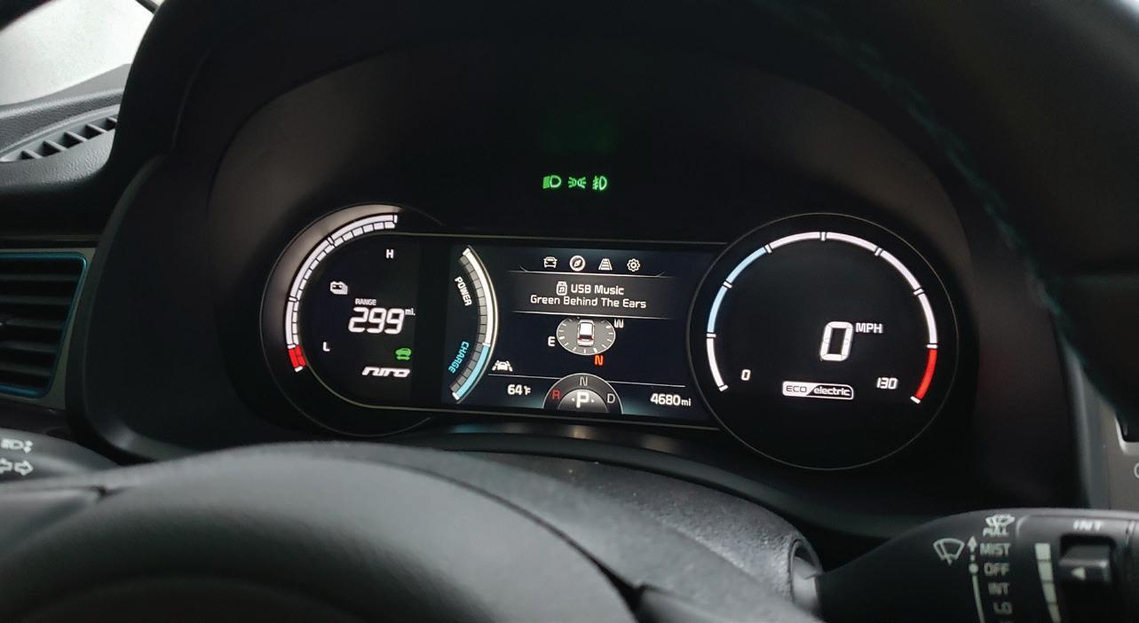
have worked for John Deere as a consultant for well over 15 years and spent many weeks in Waterloo. John Deere acquired a majority stake in Kreisel in early 2022 and has used that investment to increase battery production and improve technology. It is just a matter of time until battery storage and renewable energy will make more inroads into a fossil fuel powered world. If your shop gets in early, the learning curve is not as steep as waiting. The added benefit is that people will know your shop as the “go to place,” before your competition goes after that same EV market.

CRAIG VAN BATENBURG is the CEO of ACDC, a hybrid and plug-in training company based in Worcester, Mass. ACDC has been offering high voltage classes since 2000, when the Honda Insight came to the USA. When EVs were introduced in 2011, ACDC added them to their classes. Reach Craig via email at Craig@ fixhybrid.com or call him at (508) 826-4546. Find ACDC at www.FIXHYBRID.com.


From grungy transmissions to grimy engine blocks, nothing cleans better than Ranger’s signature stainless steel line of aqueous cleaning and degreasing systems. Durable 304 stainless steel construction is resistant to harsh chemicals and delivers the strength to endure years of hot-washing with minimal upkeep. All models feature twin heaters for quick startup, large-volume solution tanks, oil skimming system, low-water shutoff, friction-drive turntable system and gasket-free door. Beauty combined with strength, performance and durability. Order now at www.bendpak.com/wash


Klea 456A from Orbia Fluor & Energy Materials is a direct replacement for R134a, offering 50 percent less global warming potential. 456A is fully compatible with all R134a A/C systems, components, and oils. It provides a service alternative for older vehicles, allowing them to age gracefully with fully functional, responsibly serviced A/C systems.


The K-Tool International 18-Gallon Metal Oil Drain, No. KTI74552HD, is a mobile waste container and drain tank that’s air-pressurized. The drain comes with an 8” discharge hose with a shut-off valve, as well as a fluid level gauge and air pressure valve. It has an adjustable working height ranging between 45” and 70”, and the drain has two 6” fixed axle wheels and two swivel casters for easy maneuvering.


The Geodyna 980L HD Wheel Balancer from Hofmann is designed to help technicians balance wheels quickly and accurately. The balancer includes a 4/5 arm star adapter that helps position and center the wheel during the clamping process. Additional features include a raised monitor with an intuitive LED display and control panel, a user-friendly gauge arm, easyALU assisted rim measurement technology, and split weight mode that ensures accurate balancing and discreet weight concealment behind spokes.


The Coats 10K Low Rise Pad Lift offers a compact footprint and low-rise profile that collapses to 4” and lifts vehicles up to 21.4”. The lift’s drive-through design and rapid setup make it ideal for high-throughput shops. It features auto-engaging mechanical locks that ensure stability during every lift, dual mechanical lock foot releases on both sides, durable rubber lifting pads that protect vehicle frames, twin hydraulic cylinders, a corrosion-resistant frame, and a high-output Bucher pump and motor.


The M18 Dual Bay Simultaneous Super Charger from Milwaukee Tool is engineered to be Milwaukee’s fastest charger. This charger can charge an M18 REDLITHIUM FORGE XC8.0 and M18 REDLITHIUM FORGE HD12.0 battery to 80 percent in 30 minutes, and an M18 REDLITHIUM FORGE XC6.0 battery to 80 percent in 15 minutes. Designed to reduce downtime and keep users productive throughout the day.


The Snap-on Diagnostic Thermal Imager+ uses infrared technology to reveal heat caused by friction, electrical resistance, pressure changes, and more anywhere under the hood or around a vehicle. It offers detailed images composed of 4,800 distinct temperature zones and is capable of identifying temperatures up to 840 degrees F. The imager features image blending, split-screen view, picture-in-picture view, image capture, and video recording for up to 20 seconds. It includes a database of automotive applications, guided tests, and reference images to help technicians find a more accurate diagnosis in less time.


The 79” Double-bank Arca Series Roller Cabinet from Cornwell Quality Tools features a 54” W by 22” D by 10” H powered drawer that is placed higher in the cabinet than traditional roller cabinet designs. Through a collaboration with Mantis, Cornwell can provide a modular set of cordless tool holders that allow the technician to organize the drawer to their specific liking. Impacts, ratchets, drills, die grinders, and reciprocating saws can all be neatly organized in the same drawer that’s powering battery chargers and other cordless tools.


The KNIPEX 20” Big-Twin Move Tool Case, No. 00 21 41 LE, is made of heavy duty ABS material with an all-round aluminum frame center board. Each side has multi-purpose push-in facilities with elastic loops and 12 small pockets. It features a removable document compartment and a removable tool panel with 13 tool pouches. The case also has a pull-out handle and two in-line skater runners for smooth transportation without damaging floors. The case can be opened on one or both sides, the base tray and cover can be opened independently, and the case stands securely in all opening positions.


The Dual Hydraulic XTM-DMP-450 Reel from Coxreels features a unique single-sided, dual-bodied hydraulic swivel that allows the inlet connections to be on the same side of the reel. The with-hose model is a twin-line fully bonded hose for smooth performance and handling. This reel is rated to 2,500 psi and features stainless steel rollers directly integrated into the all-welded steel box frame. It comes equipped with dual permanently lubricated bearings, rigidly fixing the drum assembly to the solid 1” steel axle for consistent stability. Additional features include swivel retainers, high-temperature steel core arbors, and more.


The 2-pc Radiator Genie Pro, No. RG2, from Matco Tools, is a two-in-one wand that combines water and air cleaning for optimal performance. It includes interchangeable 50” and 22” tubes, which can be rotated up to 270 degrees for optimal positioning, and a patented fan head that enhances the pressure and working width of the spray. The RG2 also includes an interchangeable air fitting that’s compatible with various styles, including M-style connectors.


The 2236 MAX Series 1/2” Impact Wrench from Ingersoll Rand delivers 1,500 ft-lbs of breakaway torque while weighing less than 4.4lbs and with a length of 7.3” Interchangeable drives can quickly configure this tool for the job without losing power, increasing size, or needing more tools. The patented Drive XChange System lets users switch out anvils without adapters.


The High-Voltage Pack Service Tool, No. xPDC-1K, from Midtronics is a flexible platform with capabilities to meet EV battery specifications. The tool is designed to provide safe and efficient charge and/ or discharge of HV packs with control and monitoring to simplify operation. Additional features include an Android interface with on-screen prompts to perform service with minimal input, and two power level variants to match the user’s needs.


The Flexzilla Air Compressor, No. FS05V060V1, from Legacy Manufacturing, features Quiet Technology, which uses large, low-RPM pumps and motors to reduce high-frequency noise levels while increasing CFM output. Since they run slow, Flexzilla compressors also run cooler for less tank condensation and longer component life.


The Brake Caliper Hanger, No. 14880, from Tool Aid, allows technicians to hold heavy assemblies out of the way during service, preventing damage to sensitive components like brake lines. This tool is suitable for brake caliper assemblies, exhaust systems, and other miscellaneous items like extension cords. The hanger offers a secure hold without the need for additional accessories and can support a maximum weight of 100 lbs. The hanger is 9” in length.


The OTC Power Train Lift, No. 1585A, is ideal for engine and transaxle service. The lift supports up to 1,250 lbs and features a compact design with swivel casters for easy maneuverability. Its height range is 29 1/2” to 68 1/2” and has a tilting plate. The lift weighs 372 lbs.
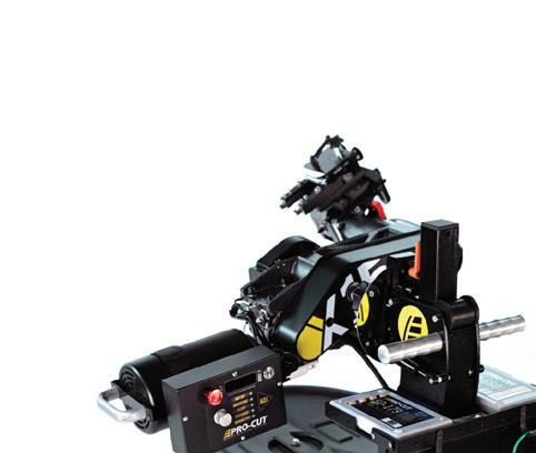


The X15 48V DC Lathe from Pro-Cut International is the only rotor-matching system driven by a 48V DC motor, according to the company. Its computer system provides disc tracking, maintenance alerts, and variable speed control. The X15 comes with a four-wheel adjustable height trolley, six adapters that cover most cars and light trucks, on-site training and installation, six on-board LED work lights, a Performance Plus cutting head that provides chatter-free surface finishes, and a two-year parts and labor warranty.


This bulletin applies to 2022 Ram 2500 and 3500 trucks equipped with an adaptive steering system and built on and after May 12, 2022, and on or before Nov. 15, 2022. A clicking or creaking noise may be heard coming from the steering column when turning the steering wheel. The cause may be a high preload in the upper intermediate shaft U-joint bearings.
Park the vehicle on a level and dry surface (not epoxy coated floor), with the engine off, ignition off, radio off, HVAC blower off, and windows closed. Rock the steering wheel back and forth between the 10 o’clock and 2 o’clock positions five times. Listen for pronounced creaking/ratcheting noises coming from under the instrument panel below the steering column. If the noise is heard, replace the steering column intermediate shaft and bolts. Always replace the upper and lower steering column pinch bolts when replacing the intermediate

shaft. A steering column upper shaft kit is available as P/N 68469694AB. The two M10 x 1.5 x 39 pinch bolts are P/N 96508531AA. (Photo: Stellantis) GMC
This bulletin applies to 2018-2023 GMC Terrain vehicles. DTC C0561 symptom 43 may be stored. The park brake will not learn after rear brake service. If the first steps of rear brake service instructions are not followed, this may result.
The brake fluid level in the master cylinder must be at half or lower to allow sufficient space for the fluid to return to the reservoir when the rear caliper retract is commanded. The caliper will retract when commanded but will stop when the reservoir is full, so the piston is not fully retracted into the caliper. If the piston is then manually pressed the rest of the way so that the caliper can be reinstalled, the excess fluid pressure will damage the pressure sensor(s) in the EBCM. The repair for this is to replace the EBCM. (Photo: General Motors)

This bulletin applies to 2016-2021 Nissan Titan/Titan XD trucks. Water intrusion into one or both of the rear combination lamp assemblies can cause multiple DTCs and can possibly prevent the engine from starting. Water intrusion has been found to migrate through the harness and can cause harness connector terminals in C1/E41 to corrode. Repair any damaged rear combination lamp assemblies immediately to avoid potential harness damage. (Photo: Mitchell 1)

Some 2023 Mazda CX-50 (2.5L with
turbo) vehicles built before Aug. 4, 2022, may exhibit a “Check Fuel Filler Cap” message in the instrument cluster. This is caused by improper control software of the PCM. When the room
fuse is installed and i-Stop is activated, the message will display in the panel for three seconds only one time and no message will return. To eliminate this concern, reprogram the PCM with
4 sensors = coverage for 225 million vehicles.
Keep the four REDI-Sensors™ on hand, and you’ll have coverage for almost every customer. No need to wait for a sensor delivery. Plus, REDI-Sensor needs no cloning or programming, so you save even more time.
the Mazda Modular Diagnostic System (M-MDS) using MDARS ECU reprogramming procedure.


After reprogramming, pending DTC P2610:00 may be stored without MIL illumination. Since this DTC may turn into a current DTC depending on operations after the reprogramming, clear the DTC after all repair work is done.
After PCM reprogramming, conduct the battery condition initial setting using Battery Condition Initialization Setting (i-Stop setting). Clear the DTC and turn ignition off and get out of the vehicle. Close and lock the door. Wait for 10 minutes or longer. Verify the repair by starting the engine and confirming that there is no check engine light or other abnormal lights present. (Photo: Mazda)
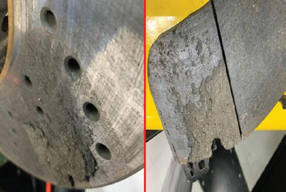
This bulletin applies to BMW M3, M4, M8, and X6 vehicles. If, after going through a car wash and with the vehicle stopped for a period of time, the brake pads may be firmly corroded to the brake discs due to a chemical reaction of the cleaning agent. After cleaning, take a short drive, lightly applying the brakes for about five to 10 seconds to dry them.
Only use a chemically neutral wheel cleaner containing pH values that range from 5 to 9. Do not use an abrasive cleaning agent and avoid high temperature pressure washers


or steam jet cleaners which have operating temperatures above 140 degrees Fahrenheit. Use of aggressive, acid- or alkaline-based cleaning products can destroy the protective layer on adjacent components such as the brake disc.
(Photo: Mitchell 1)


Some 2018-2022 Ford Mustang vehicles may exhibit various concerns with the active exhaust system. These may include Drive Mode Not Available or Exhaust Mode Not Available messages, and/or illuminated MIL with DTC P26C5, P26C6, P26FE, P2BF9, P2BFB, P26C7, P2BF5, P2BF8, P2BFD, and/or P2BFA. This may be due to an improperly seated exhaust system.
1. Are DTCs P26FE or P2BFB present? If yes, proceed to Step 2. If no, proceed to Step 5.
2. Using the appropriate Ford diagnostic scan tool, access datalogger and view the PCM parameter identifications (PIDs). Monitor the EFCV_A_MON_STAT PID while active commanding the EFCV_A_CMD PID. Open the tailpipe actuator in 10% increments until it has reached 100% (fully open). Then close
the tailpipe actuator in 10% increments until it is fully closed. Does the EVCA_A_ MON_STAT PID display a mechanical fault at any point? If yes, proceed to Step 3. If no, proceed to Step 5.
3. Remove the exhaust actuator and inspect for physical binding and/or blockage and repair as needed.
4. If the concern is still present, proceed to Step 5.
5. Inspect the muffler and tailpipe assembly and both catalytic converters for proper positioning in the exhaust clamps. Make sure that the exhaust clamp locking tabs are fully engaged to the converters. Make sure that the knurled/ridge area of the muffler and tailpipe assembly are covered by the exhaust clamps.


The Mini-Ductor® Venom HP is the premier mini induction™ heater, delivering safe, fast, and precise heat for removing rusted, corroded, or seized parts — all without open flames!
Perfect for:
• Rusty bolts, nuts, and fasteners
• Stubborn adhesives and decals
• Automotive, construction, and maintenance
through your local tool distributor. Heat it. Don’t torcH it.


6. Inspect the exhaust actuator wiring harness for damage. Replace damaged harness with P/N 14A411. (Photo: Ford)

Engines in 2009-2016 Audi A4, A5, A5 Cabriolet, A6, Q5 and TT vehicles equipped with a 2.0L TFSI Evo2 engine may run rough/erratically. There may be no DTC stored in the ECM. The cause may involve a faulty air mass meter. Disconnect the air mass meter connector and perform a test drive and see if the complaint persists. If it does, do not replace the air mass meter, as the cause lies elsewhere. Look for other possible causes such as air leaks in the intake system, a dirty

When it comes to timing chain replacement, there can be no compromise. SKF Timing Chain Kits are tailored to your vehicle’s specifications, ensuring precise setup and long-lasting performance. With high-strength steel chains, hydraulic tensioners, and heat-resistant guides, SKF delivers exceptional durability, efficiency, and reduced wear. For technical support and insights, visit: vehicleaftermarket.skf.com or scan the QR code to know more about the SKF products.
or incorrectly-fitted air filter element, etc. If the complaint does not persist, replace the air mass meter. (Photo: Audi)

This bulletin applies to 2022 Chevy Bolt EV and Bolt EUV vehicles. The Service Engine Soon light may be on. Technicians may find DTC P0534 set. This condition may occur without a customer concern of A/C performance and without the presence of any leaks in the system.
The cause may be a glitch in the K114B Hybrid/EV PCM 2 software that sets the DTC. Check the function of the A/C system and check for visible leaks in the system. If leaks are detected, follow service manual diagnostics to repair and update the K114B Hybrid/EV
powertrain control module 2 with the latest software. If no leaks are found and the A/C system functions properly, perform the software update. (Photo: Chevrolet)

This bulletin applies to 2020-2024 Subaru Legacy and Outback and 2019-2024 Forester vehicles. New reprogramming files are available for the ECM. These files have been developed to address concerns of the starter motor not operating in cold temperatures of less than 32 degrees Fahrenheit. DTC P0890 (TCM power relay sense circuit low) will likely be stored in the ECM. Condensed moisture in the ignition relay can cause the contact points to freeze. The new logic enhances the relay self-shutdown

program, eliminating the possibility of frozen contacts. In addition, this logic also contains optimized software for the thermos control valve (MCV) to prevent any misdetection of DTC P26A. (Photo: Subaru)

This bulletin applies to 2021-2024 Buick Envision vehicles equipped with a 2.0L engine. The MIL may be on, with DTC U0672 set current or in history. Check for and correct any related wiring contamination, terminal tension, crimp, or lock issues as needed. If no issues are found, cycle the Electric Engine Coolant Pump connection and clear the U0672. If the code does not reset, release the vehicle to the customer. (Photo: General Motors)
THERE ARE MANY SERVICE OPERATIONS that don’t require a vehicle to be six feet in the air. Wheel, tire, and brake work for example, can all be done with the vehicle just a few inches off the ground. For this reason, many shops use floor jacks instead of car lifts for these tasks.
But, constantly positioning and operating multiple jacks per vehicle is time-consuming and tiring. Using floor jacks forces technicians to kneel, squat or bend to remove and install heavy wheels and tires. This can lead to back, knee and other injuries, especially with an aging technician population.
Moving from jacks to two-post lifts can improve technician ergonomics, reduce the chance of technician injuries, and increase productivity, especially in express service lanes. However, some shop owners worry that two-post lifts come with additional risk.
Here are 5 tips for mitigating risk when using two-post lifts in bays focused on wheel, tire and brake work.
1. Limit how high technicians can raise vehicles. In shops with existing two-post lifts, the limit might be a specific lock position. If the shop is installing new lifts, consider a short-rise two-post lift model. The new BendPak 12APSRT lift, for example, has a maximum lifting height of 47

inches, so there’s no chance technicians will raise it any higher. But with a rated capacity of 12,000 lbs., ability to reach most OEM lifting points, and the versatility of both symmetric and asymmetric lifting, a 12AP-SRT lift can raise 99 percent of cars, trucks and SUVs to a comfortable working height quickly and easily.
2. Choose ALI Certified lifts. Professional shops deserve professional-grade equipment. Look for the Gold Label or check the Directory of Certified Lifts at autolift.org to confirm that a lift has been third-party tested and certified by the Automotive Lift Institute (ALI) to meet industry safety standards.
3. Train technicians. All technicians should be trained on how to use the specific lifts in the shop as well as safe lifting practices. This training should include proper spotting, lifting, and lowering procedures.
4. Consider safety features. Safety features vary widely among lifts and lift manufacturers. Look for automatic safety locks in every column, a single-point lock release, and the strongest possible automatic arm restraints.
5. Regularly inspect and maintain the lifts. Technicians should check the lift daily prior to use. Have every lift professionally inspected by an ALI Certified Lift Inspector annually to ensure it’s in proper working order. Follow the instructions in the lift operator manual for specific maintenance requirements.
New professional short-rise two-post lifts like the BendPak 12AP-SRT offer the versatility, productivity and ergonomics of a full-size two-post lift with lower costs and less risk.


BY BRANDON STECKLER // Technical Editor
MOTOR AGE TECHNICAL EDITOR Brandon Steckler is in the midst of a system and component mini-series within The Trainer, and this time the focus is on solenoids. And what’s the significance? Regardless of the year, make, model of the car, or even the name of the component (or what its purpose is), a solenoid is found on virtually every single vehicle you will face in any shop on the planet!
True to form, Brandon focuses on physics as it should be used as a crutch we can lean on. Physics cannot be changed, why not embrace these laws
and use them to your advantage? This will provide insight into component functionality. More importantly, it will serve to drive anticipation during evaluation of component functionality.
Brandon takes the time to first visit service information to examine the wiring diagram and identify the functionality of the two-wire solenoid circuit. After that, Brandon transitions into the tools of the trade that can be applied to any circuit out there, and how to leverage the tools to gain an edge in diagnostics.
Finally, Brandon captures the wave-
forms relating to solenoid functionality and examines the exhibited characteristics, sharing with you the significance of each portion of the captured waveform. It’s these analytical techniques that Brandon leveraged in the trenches to make accurate and efficient diagnostic decisions without much time or energy invested.
If you want to know what it takes to evaluate all aspects of a solenoid’s functionality without disassembly or guesswork, you don’t want to mis this episode of The Trainer!


FOLLOW MOTOR AGE MAGAZINE ON YOUTUBE TO SEE NEW VIDEOS AS THEY ARE RELEASED.