


Instruction list is no longer part of IEC 61131-3, but ladder diagram, structured text, sequential function chart and function block diagram are being explored in new ways


Need your variable speed drive to have an easy and problem-free connection to your favorite Ethernet or Fieldbus network? Yaskawa takes your desire for control and data seriously.
Our new GA800 is no exception. It provides data-rich connectivity with all major industrial networks. The Industrial “Internet of Things” is here. Let Yaskawa help satisfy your appetite for it.

Your days are complicated enough. Let us help simplify them. Call Yaskawa today at 1-800-927-5292.


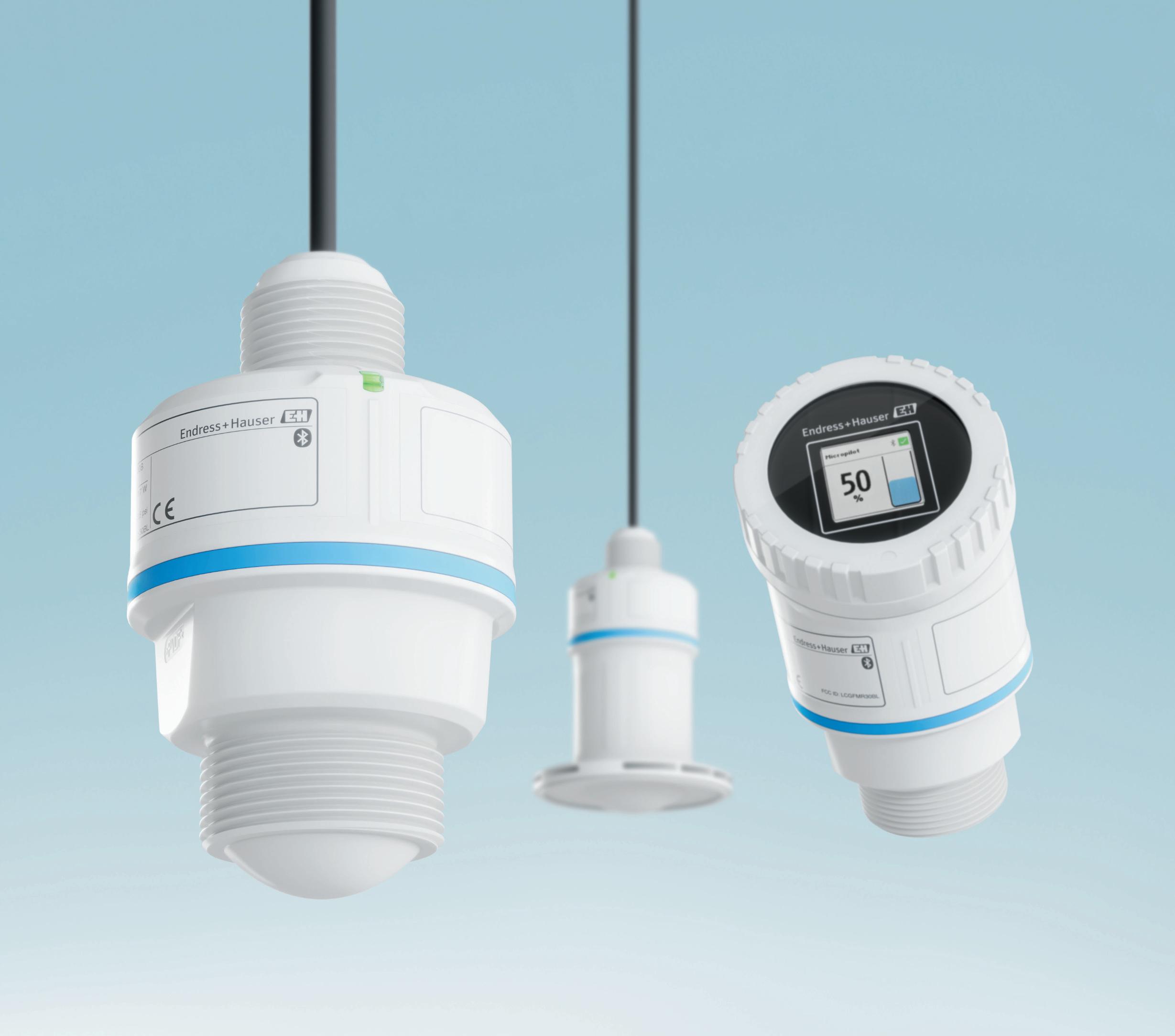
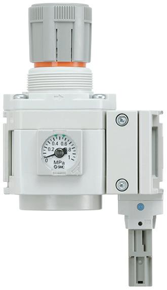
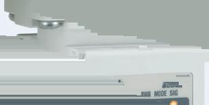
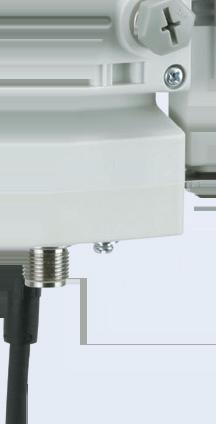
Endres s+Hauser ’ s Micropilot radar sensors FMR10 , FMR20 and FMR30 s tand out with fas t commis sioning and intuitive operation Setup wizards guide you through each s tep –your de vice is ready to use in les s than 3 minutes.

cover story
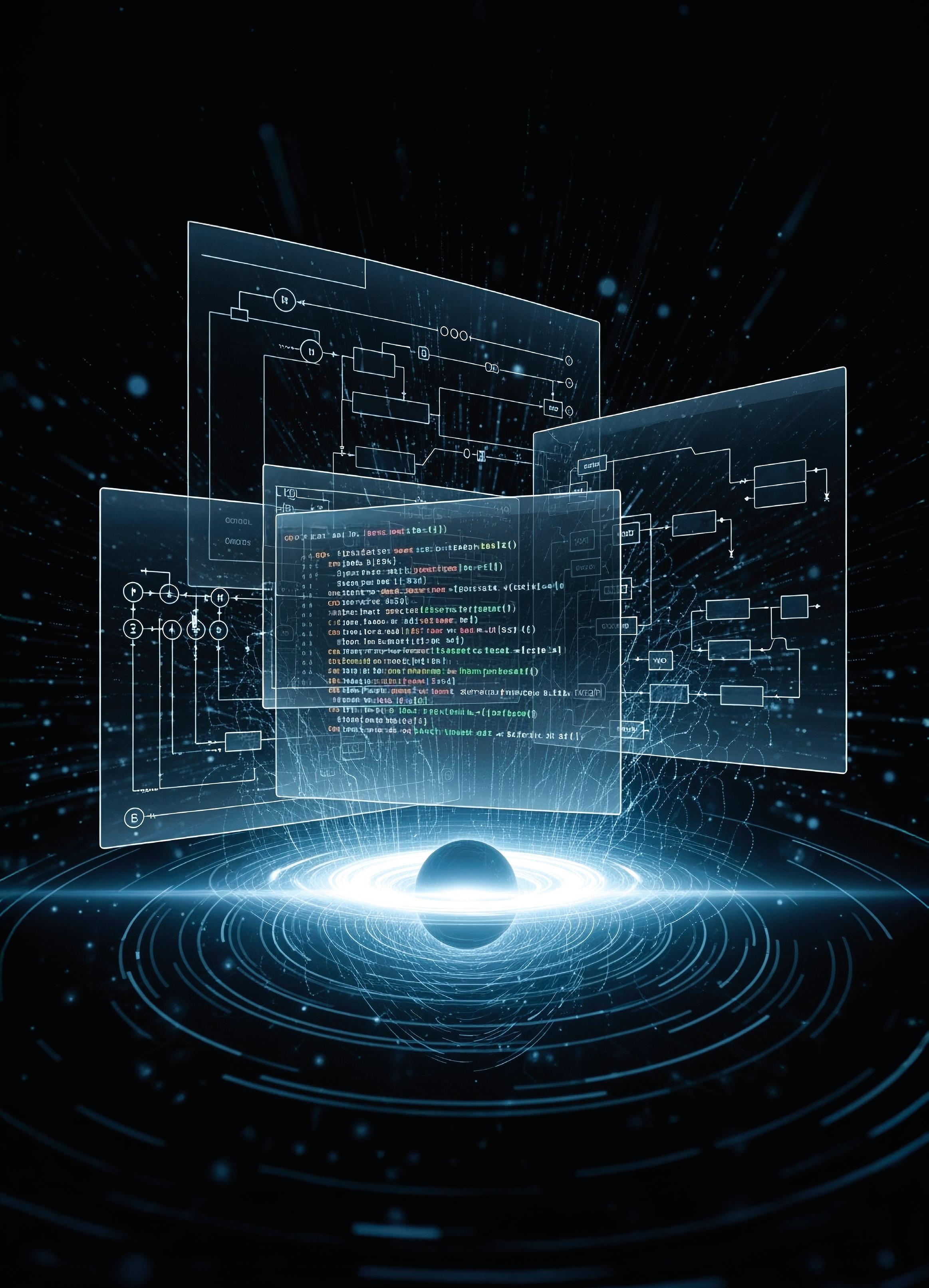
PLC programming expands its universe
Instruction list is no longer part of IEC 61131-3, but ladder diagram, structured text, sequential function chart and function block diagram are being explored in new ways
Anna Townshend, managing editor
machine input
How are PLC R&D teams affected by SDA?
Protocol and standard adaptability makes software-defined automation impervious to obsolescence
Mike Bacidore, editor in chief
SCADA From spaghetti to a structured blueprint How object-oriented SCADA enables scalable, replicable industrial control systems
Nestor Arria, Disruptive Automation Solutions
product roundup Motors, motion, movement and more Components and devices to drive actuation


CEO
Endeavor Business Media, LLC
30 Burton Hills Blvd, Ste. 185, Nashville, TN 37215
800-547-7377
Chris Ferrell
COO
Patrick Rains
CDO
Jacquie Niemiec
CALO
Tracy Kane
CMO
Amanda Landsaw
EVP Manufacturing & Engineering Group
Lisa Paonessa
VP Corporate Content
Travis Hessman
VP Content Strategy Manufacturing & Engineering Group
Robert Schoenberger
Group Editorial Director
Keith Larson
editorial team
editor in chief
Mike Bacidore
mbacidore@endeavorb2b.com
managing editor
Anna Townshend
atownshend@endeavorb2b.com
digital editor
Madison Ratcliff
mratcliff@endeavorb2b.com
contributing editor
Rick Rice
rcrice.us@gmail.com
contributing editor
Joey Stubbs contributing editor
Tobey Strauch tobeylstrauch@gmail.com
contributing editor
Charles Palmer charles101143@gmail.com
columnist
Jeremy Pollard jpollard@tsuonline.com
design/production
production manager
Rita Fitzgerald
rfitzgerald@endeavorb2b.com ad services manager
Jennifer George
jgeorge@endeavorb2b.com art director
Derek Chamberlain
subscriptions
Local: 847-559-7598 • Toll free: 877-382-9187
email: ControlDesign@omeda.com
sales team
Account Manager
Greg Zamin gzamin@endeavorb2b.com
704/256-5433 Fax: 704/256-5434
Account Manager
Jeff Mylin jmylin@endeavorb2b.com
847/516-5879 Fax: 630/625-1124
Mike
Jeremy
Rick Rice, contributing editor
component considerations Make smarter drive choices for equipment
Tobey Strauch, contributing editor 14 automation basics Robotics’
Charles
contributing editor
Joey Stubbs, contributing editor


Elevate your energy infrastructure with IIoT-enabled HPS Smart Transformers.


Mike Bacidore editor in chief mbacidore@endeavorb2b.com
MITSUBISHI ELECTRIC IS READY to put a ring on it. Its collaboration with Nozomi Networks, which specializes in cybersecurity for OT, Internet of Things (IoT) and cyber-physical systems, has been expanding for well over a year.
Now, it’s official. Nozomi Networks will become a wholly owned subsidiary, operating independently of Mitsubishi Electric. The acquisition is designed to strengthen Mitsubishi Electric’s Serendie-related business, which includes OT security. Serendie is a digital platform designed to foster serendipitous data, human and technology encounters. Its name is coined from the combination of serendipity and digital engineering.
“We’ll be implementing Nozomi’s business assets, such as SaaS products, cloud-service platform and AI technology to strengthen Serendie business quality,” said Satoshi Takeda, Mitsubishi Electric senior vice president, CDO, chief information officer and board member. “We will place Nozomi’s OT security technology into our components, as well. An example is in the sequencer, equipped with intrusion detection sensor, which was launched in September 2024 to enforce edge security.”
zomi data collection technology, we’ll be able to get rich data from the site. Through our Serendie, we will fully utilize this data to create a new service, along with our customers.”
Nozomi technology is being used in 75 countries with a customer base of 1,000 companies, not just in manufacturing, but in building and infrastructure, said Takeda.
In the industrial automation area, multiple suppliers have collaborated with Nozomi. Yokogawa began offering Nozomi’s OT visibility and threat detection to its OpreX Managed Services customers in 2024, and in 2025 Nozomi announced its Arc Embedded was embedded in Schneider Electric’s SCADAPack 47xi smart remote terminal units (RTUs).
Nozomi technology is being used in 75 countries with a customer base of 1,000 companies.
Mitsubishi Electric’s MELSEC iQ-R programmable logic controllers (PLCs), as well as the field assets these PLCs control, down to levels 1 and 0 in the Purdue Model, include Nozomi Arc Embedded, which provides real-time visibility of internal operations. The data collected by Arc Embedded enhances anomaly and threat detection.
“The biggest aim will be co-creating new services by utilizing data,” added Takeda. “Nozomi’s solution does not just strengthen security, but will enable data collection in the overall OT arena. This is an area where various components from different vendors operate in data collection. Origins or meanings of the data were often missing. There were issues at the time of analysis and utilization of data. By using No -
Mitsubishi Electric participated in Nozomi’s $100 million Series E funding round in March 2024, and the two companies have collaborated on innovation ever since.
“Mitsubishi Electric purchasing Nozomi Networks signals that OT/IoT capabilities are being valued in the cybersecurity arena, data services and with artificial intelligence,” said Tobey Strauch, a controls engineer and a contributing editor to Control Design who wrote about the deepening relationship between Mitsubishi Electric and Nozomi Networks more than a year ago. “When traditional hardware companies are expanding OT interface capacity, then you know the importance of data, even in the OT environment. Every machine will be connected. Companies are profiting by doing so.”
The acquisition of Nozomi Networks brings an AI-powered, cloud-first cybersecurity software business with scalability to Mitsubishi Electric.
How will the Nozomi technology in other suppliers’ components be supported, and how will the fruits of these serendipitous data encounters be shared? Stay tuned. Exciting times are ahead, as AI and cybersecurity move deeper into the manufacturing space.

Jeremy Pollard jpollard@tsuonline.com

INDUSTRIAL ETHERNET IS the same as commercial Ethernet, except for the hardware, which has been hardened for the factory floor. TCP/IP is widely used, along with specific protocols such as Ethernet/IP and Modbus/TCP.
It has become a de facto standard in plants and machines for interconnecting systems and in fact individual devices. So, what happens when it fails? What would make it fail?
I read a post on LinkedIn that went something like this: The plant warehouse management system (WMS) stopped communicating with the programmable logic controller (PLC) that had all the connected sensors attached to it. The first step in troubleshooting this issue was to check the PLC code, wrote the author.
Evidently the PLC code checked out. Everyone commented that it’s the WMS that isn’t communicating.
col (ICMP). This tests the physical cable, as well as the integrity of both ends of the message route. A positive ping response suggests that the link is alive and responsive at both ends.
If the ping command fails, it suggests that one of the nodes is disconnected from the network. Most if not all Ethernet ports have two indicating lights—one that blinks with activity and a second LED that indicates the link connectivity and the speed at which it is connected. Note that, for 10 MBPS, that light will be off, so it’s important to know the configuration.
If the ping command fails, it suggests that one of the nodes is disconnected from the network.
The next frame on the graphic shows the Ethernet connection, and funnily enough it shows a failed diagnostic light. The resulting reboot of the WMS fixed the problem.
It probably was a Windows-based computer running the WMS, which leads us to a probable option of the PLC driver going off-line. The diagnostic failure light on the switch, router or PLC indicates that there was a network failure of some sort. It wasn’t clear as to where it was.
So, a review of the systemic information should have taken minutes and not the 13 hours the author suggests it took to find and fix the issue.
What if there was no failure light? How do we troubleshoot network issues, and what tools do we have to help?
There may be helpful displays on the PLC itself, or maybe not. A network mapping tool would be helpful which would show the user what devices are successfully connected to the network and in the same subnet. The IP address range for areas of the plant and/or machine typically will be the same and typically connected to the same group of switches.
The mapping tool will tell you if a node is off-line and not responding. If the link is alive and well, then the issue would typically be a software or message-framing issue.
Step one is to confirm cabling on a network computer with the ping command using the Internet control message proto-
Ethernet modules check for situations such as jitter, which is, in one word, inconsistent. This can be due to many things such as network congestion, which can happen when an Ethernet module or card goes rogue. This typically suggests that a piece of hardware is intermittently failing.
This is not an easy find however and may require a deep dive into the network.
There have been times when a port on a switch drops the connection, and a power cycle was required to bring it back online. With a Windows computer and application, a restart is successful some of the time.
In the above case, that is what restarted the communication between the WMS and the PLC, and the user had the benefit of a diagnostic LED to aid in the troubleshooting.
In the event of not having that periscope into the network, tools such as protocol monitoring software may be needed to find a rogue node.
If the systems are connected to a managed switch, there are various interfaces that a user can use to monitor each node and view the configuration.
There are various ways one can troubleshoot a communication issue within a subnet, and activity lights and link connectivity lights would be the first step. Specific hardware device status lights may be present.
JEREMY POLLARD, CET, has been writing about technology and software issues for many years. Pollard has been involved in control system programming and training for more than 25 years.

Rick Rice contributing editor rcrice.us@gmail.com
IT’S HARD TO ADMIT IT, but perhaps we do get more complacent with time and resistive, perhaps ignorant, of change. After nearly four decades in this compelling industry of controls and automation, a lot of knowledge and experience is crammed into this old brain of mine. I have always prided myself on keeping up with technology, and I am always scanning the myriad emails I get each week extoling the virtues of the next greatest thing from my favorite vendors.
After the scramble around the pandemic to get parts to complete controls projects, I would have to say that I am significantly more open to considering products that wouldn’t have been on my radar even months before. With all the buzz around tariffs now, I wonder if we are, once again, going to find ourselves opening up our choices to the realm of possibilities from previously unrecognized sources.
Our interaction with the newer generation came in the form of simply having some bits to exchange back and forth with our line control panel so we could tie all the various unit ops together and do some data collection for our OEE software package.
At first glance, the newer PAC looks mostly like a cosmetic change to what I would call more of a European look with removable spring-load terminals. However, the real changes are inside the package.
Working with the PAC/safety controller has been an eye-opening experience for us.
As it happens, this is a very busy time at my place of employment. We currently have four major capital projects on the go with startups scheduled for January through September of next year. These are exciting times for our controls team as the projects are new production lines and heavily automated.
Building structures are being modified. New utilities are being deployed to service the production space. Integrating all the various parts is a huge endeavor that is elevated by the fact that we have multiple projects on the go at the same time.
We are a small group, and, like many small companies or integrators out there, we rise to the challenge when a bigger project comes in. We have great successes in our past endeavors and try to do each project better than the one before. An essential part of this is to be aware of advances in technology and utilize them in our designs when they make sense.
A great example of technology helping a design came in the form of a newer generation of programmable automation controller (PAC) from our favorite hardware supplier. This new generation has been out for nearly two years now, but, aside from finding them in some vendor-supplied equipment, we really haven’t taken a close look at the product because our existing generation of PAC is still actively available, and it does everything that we’ve asked it to do.
Compliance with the IEC 61131-3 programming standard necessitated a change in some of the traditional ladder-logic instruction mnemonics. For newer programmers who are accustomed to clicking an icon to insert an element into a software design, this change might not even get noticed. However, for those of us who have been around for more than 20 years or so, this change is quite uncomfortable.
For example, the traditional GRT (Greater Than) is now GT. LES (Less Than) is now LT. These might seem like ridiculously insignificant changes, but for those of us who have programmed by entering text on a line, the change is like learning to speak French when all you know is English, but having to do it in a few hours.
Fortunately, or perhaps less fortunately, the vendor provides an “automated” way of upgrading a software application that was created in a previous firmware revision to this later hardware and firmware. The surprise was that the transition forward converts most of the application but flags the “old” instructions as not being recognized, instead of just going ahead and updating them.
One larger program that I recently migrated to the new firmware/hardware resulted in nearly 1,000 instances of an instruction that I had to manually navigate to and convert to the new instruction.
Another surprise was the dropping of some traditional instructions and changing them over to function block (FB). One example is the SCL (Scale) instruction. For someone without previous experience with FB, this would be a very big surprise. Further bumps in the road happen if your
software platform is a legacy version—for me, that was just 14 years ago—where FB, structured text (ST), instruction list (IL) and sequential function chart (SFC) were not part of the original hardware platform but were added in the ensuing years. That surprise resulted in having to purchase further licenses in order to include that feature in our base of installed software development laptops. This isn’t as important if you are just troubleshooting but hugely important if you are developing new code.
In our usual control design, we pick our favorite model of PAC with the favored firmware level installed and then include a safety relay in the design. The hardware vendor makes that part even nicer by having an interface module that connects the PAC to the safety relay using Ethernet/ IP. It turns out most of the safety relays can communicate across an optical bus that is already built in. Just add the comms module, and you can get status from the channels and nodes on the relay plus have control over the outputs on things like door latches.
This brings us to a big feature in our newer PAC platform—the ability to include a safety processor with the logic processor. For sure, this is not that new of a feature but if you are happily building controls using the now mature generation of PAC, the thought would not even come to mind. In fact, our experiences, thus far, with the new generation of PAC did not expose us to the embedded safety controller.
During the process of working out the integration for our newest production line, we learned that several of our equipment vendors will be providing the dual-processor PAC in their designs. Curiosity, they say, kills the cat and there we were diving down the rabbit hole to see what all the fuss was about. To find out that our hardware vendor is offering safety and non-safety PACs at the same price pretty much sealed the deal for us.
The financial gain by buying a PAC with a safety controller included was significant. The comms module and safety relay are fairly expensive on their own. Taking that cost out of the design was a bonus, as was being able to use the same safety devices that we were using previously. There was no reason not to change.
When using a dual-processor PAC, one adds slices of input or output modules that are specifically for safety. They are even colored red to differentiate from normal I/O modules. The slices only come in eight-input or -output versions because the safety devices are two-channel. If desired, we can
use a field-mounted interface module that communicates on Ethernet/IP with the safety controller.
Where one might use the IO-Link type safety network and nodes with the separate safety relay, the field interface module provides a means of connecting the M12 terminated safety channel directly to the module and, thus, to the safety controller in the PAC.
Programming with a safety controller is less complicated as we simply wire up each of the safety devices to a channel on the safety I/O module and use software to create the combinations of inputs that will produce an outcome on a channel on the safety output module. With the safety controller being part of the PAC, we also have a direct connection with the safety outputs that form the dual channel Safe Torque Off (STO) feature on our servos and variablefrequency drives (VFDs).
The only caveat that we found in our experience with the PAC/safety controller was that our programming software, yet again, didn’t have the safety programming module enabled on it, and, yet again, we were back to the vendor to buy licenses for the computers that will be developing code for the safety side of things.
There is a price, it seems, for hanging on to legacy hardware and software for too long, even if it is still available from the hardware vendor.
Teething issues aside, working with the PAC/safety controller has been an eye-opening experience for us. With six out of the 10 units of operation on our new production line coming with the dual processors, we decided to jump into the fray and designate one of these newfangled things for our main-line control cabinet. The ability to program both the main control algorithm, as well as the safety zones and devices of our line, with the same single point of connection and program application has us placing a whole new emphasis on this approach as a default direction for us in future projects.
With three other production lines going in within the next nine to 12 months, we anticipate some good practical experience to go with our decided path. We already love it, and we don’t even have the panel built yet. The off-line design and development of the software application is already seeing a savings in time and money.
RICK RICE is a controls engineer at Crest Foods (www.crestfoods.com), a dry-foods manufacturing and packaging company in Ashton, Illinois.

Tobey Strauch contributing editor tobeylstrauch@gmail.com
IN A WORLD OF BLACK-BOX MAINTENANCE and increased prices, where time is precious, how do you know what kind of drive to choose for your application? Choices and brands are abundant, but choosing a drive can be difficult or confusing. For the sake of simplicity, let’s consider drives supporting motors under 70 hp and simple inductive ac motors. Things to keep in mind:
1. Application requirements: How do you want to control the function of the motor? Speed, torque, precision? It’s good to know what you are moving, how fast and to what degree of error you may have.
2. Environment: Is the environment harsh, wet, oily, dry, hot? Ruggedized electronics will be needed in specific cases.
stored and loaded from the PLC. This includes motor voltage, motor current, motor frequency, motor speed, motor power or kilowatt rating and motor type.
Control parameters can be tabled with acceleration time, deceleration time, minimum and maximum speed boundaries in revolutions, Hertz or some unit derived thereof, stop/ start mode and control mode.
Communication settings might be monitored for validating that the drive is on the network.
3. Safety: What features do you want the safety to have? Safe torque off is a go to for most environments and applications.
4. Control: How many inputs can the drive take? Is there an option to program the inputs without a programmable logic controller (PLC)? How does the PLC need to interface? Do you need to buy software to program the drive, or can you do so from the PLC, or is there an interface?
5. Communication: It’s imperative to get a drive that fits the communication architecture and that can provide feedback for control. This means, adaptations, such as Ethernet, Profinet, Modbus, EtherCAT. When purchasing, it’s good to understand the availability, lead times and the cost of ownership. Many maintenance departments want to standardize on a brand due to company preference and engineer/technician comfort. Familiarity sells. There can be a dependence on who the plant sees the most often, as far as field support. Industries also have their favorites based on the history of what automation brand supported that industry from its inception.
Most of the drives supporting the lower hp market are going to be similar. Things to consider at that point are price, integrability with the PLC platform, reliability and trainability. Keep in mind also that, just because one may grab the 1,000 parameters on a drive from the Ethernet, it does not mean that you should. Basic motor parameters may be
Input and output parameters are discrete for start, stop, forward, reverse, analog for speed reference and torque feedback. Relay outputs may have status signals like running or drive fault. Analog outputs include current and speed feedback to validate that the drive spun up to the command given. Communication settings might be monitored for the purpose of validating that the drive is on the network. The PLC should throw an alarm if it does not see the hardware. Network addresses could be assigned at the switch or in the PLC to allow for hot swaps without having to program the address. Protocol selection is a parameter that is important.
Overload and protection settings may be monitored by the PLC and human-machine interface (HMI) for the purpose of drive health.
This would include overcurrent, temperatures and overspeed, with voltage and frequency limits.
Specialized feedback may be required for tuning or proportional–integral–derivative (PID) settings. This includes auto-tune capacity and torque boost. Specialized parameters would depend on the application and would be subject to maintenance accessibility. Sometimes customers want these on the HMI display.
Keeping a table of parameters for each drive and knowing where the drive stores them will allow for reading and writing parameters in specific modes or when a status changes so that traffic from drives may be limited. Better yet, if drives are put on their own subnet, then drive traffic can be isolated from process and not cause other issues.
Tobey Strauch is an independent principal industrial controls engineer.
Charles Palmer contributing editor

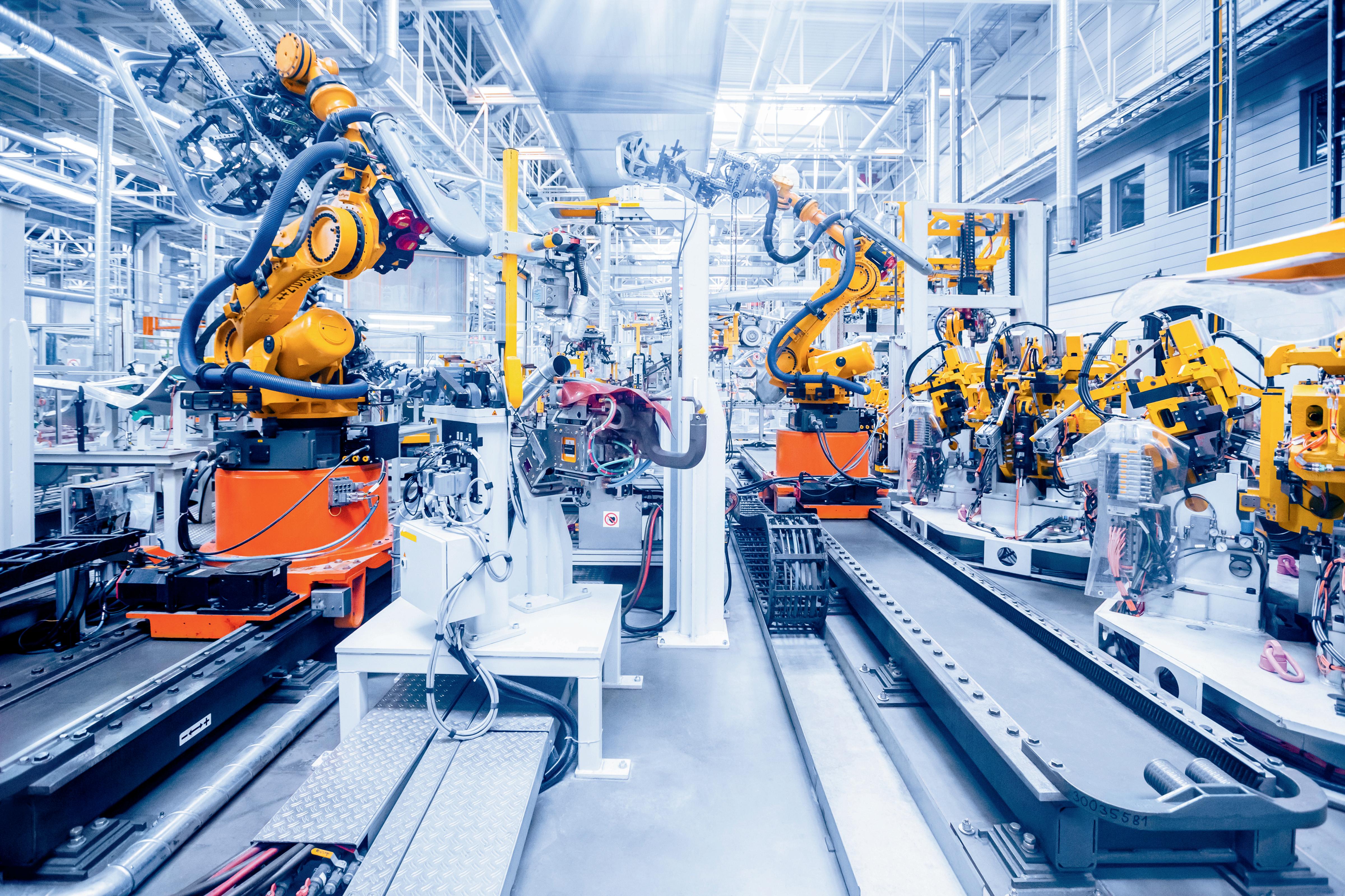
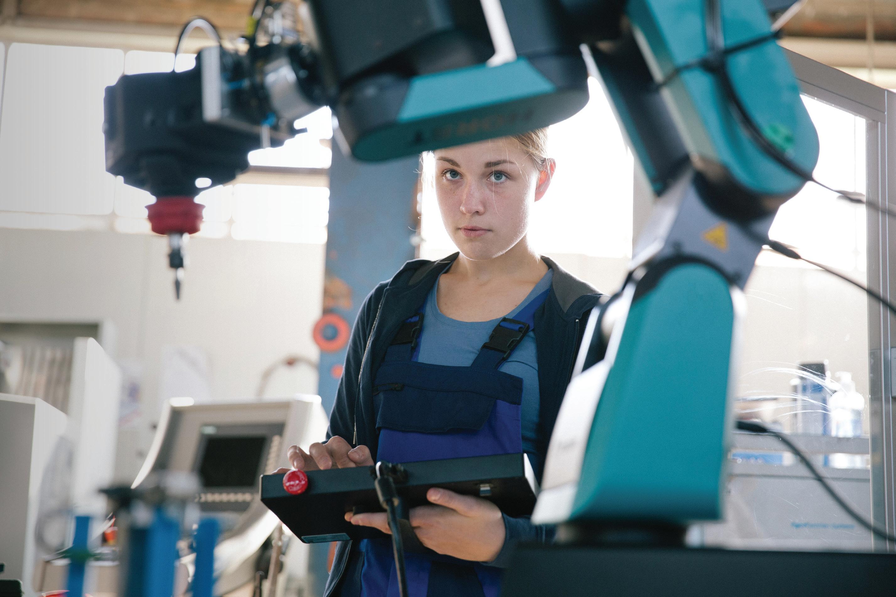
THE LANDSCAPE OF INDUSTRY is undergoing a profound transformation, largely driven by the increasing integration of robotics. Once confined to the realm of science fiction, industrial robots are now an indispensable part of manufacturing and production processes worldwide. This shift is not merely about automation; it represents a paradigm change in how goods are produced, supply chains are managed and human labor interacts with advanced machinery.
Industrial robots are deployed across a vast array of applications, revolutionizing production processes in numerous industries. Their versatility allows them to perform tasks ranging from repetitive, highvolume operations to intricate, precision-demanding procedures. The manufacturing sector, particularly automotive, electronics and metal industries, has been at the forefront of adopting robotic solutions.
extreme temperatures or repetitive motions that can lead to musculoskeletal injuries. By taking over these tasks, robots create a safer working environment.
The choice of robot type depends on the specific application, required precision, payload capacity and reach.
While the initial investment in industrial robots can be substantial, the long-term cost savings are significant. Robots reduce labor costs, minimize material waste due to errors and decrease energy consumption through optimized processes. Furthermore, their consistent performance and reduced downtime contribute to a higher return on investment (ROI) over time. The falling prices of robots and increased accessibility have made automation more economically viable for a wider range of businesses, including small and mediumsized enterprises.
The integration of industrial robots offers a multitude of benefits that significantly impact productivity, quality, safety and cost-efficiency in manufacturing and other industrial sectors. These advantages are driving the widespread adoption of robotics globally.
Robots can operate continuously without fatigue, breaks or performance degradation, leading to significantly higher throughput and production rates. They perform repetitive tasks with consistent speed and accuracy, reducing cycle times and optimizing the overall manufacturing process. This continuous operation maximizes machine utilization and streamlines workflows, resulting in increased output and improved efficiency.
Another advantage of industrial robots is their ability to perform tasks with extreme precision and repeatability. Unlike human workers, robots do not experience variations due to fatigue or distraction, ensuring uniform product quality and consistency. This leads to fewer defects, reduced rework and less material waste, ultimately improving the overall quality of manufactured goods.
Robots can handle dangerous, dull, and dirty tasks that pose risks to human workers. This includes operations involving heavy lifting, exposure to hazardous materials,
Industrial robots are highly flexible and can be reprogrammed and reconfigured for different tasks and product variations. This adaptability allows manufacturers to quickly respond to changing market demands, introduce new products and customize production runs without extensive retooling. This agility is particularly beneficial in industries with short product lifecycles or high customization requirements.
Robots often have a smaller footprint compared to traditional machinery or manual workstations, allowing for more efficient use of factory floor space. Their ability to work in confined areas or perform multiple tasks within a compact cell further optimizes space utilization.
Many industrial robots are equipped with sensors that collect vast amounts of data on their performance, production metrics and environmental conditions.
This data can be analyzed to identify bottlenecks, optimize processes, predict maintenance needs and make informed decisions to further enhance operational efficiency and productivity. This integration with the Internet of Things (IoT) enables predictive maintenance and smarter manufacturing processes.
Charles Palmer is a process control specialist and lecturer at Charles Palmer Consulting (CPC). Contact him at charles101143@gmail.com.


Protocol and standard adaptability makes software-defined automation impervious
by Mike Bacidore, editor in chief
THESE INDUSTRY VETERANS shed some light on the increasing use of software-defined automation.
Mark Collins is a senior engineer at Mazak with a bachelor of science degree in electro-mechanical engineering from Miami University. With more than 25 years of experience in a variety of roles in the manufacturing and machine tool industry, Collins has acquired a breadth of experience in robotic automation, machining process, industrial networking and security. He is looking forward to seeing how artificial intelligence, big data and the continued move toward a more connected manufacturing industry will affect the future of manufacturing.
Sarah McGhee is product owner, Simatic AX, at Siemens. Thomas Kuckhoff is product manager of core technologies at Omron Automation Americas.
Michael Kleiner is vice president (VP) of edge AI solutions at OnLogic.
Rahul Garg is vice president, industrial machinery, at Siemens Digital Industries Software.
Kurt Braun is director of automation sales engineering and development at Wago.
Ken Crawford is senior director of automation at Weidmuller USA.

Ken Crawford, senior director of automation, Weidmuller USA : The primary focus so to allow a high level of hardware integration into a software platform where you can condense and consolidate a lot of features and functionality into a single hardware platform that runs and supports a wide range of applications that define the platform’s operation and decouple the hardware dependencies from the software. An early example is when the relay logic technology back in the 1970s was replaced with programmable logic controllers (PLCs) that eliminated the
hardwiring of relays that acted like a sequential logic engine to define a process. Once these rigid and nonflexible circuits were deployed, changes were very slow to make and very costly. With a programmable controller, software defines the logic and operation, making it much quicker and easier to instantiate changes. This makes the system much more flexible, scalable and adaptable for many applications.

Kurt Braun, director of automation sales engineering and development, Wago : The primary focus of softwaredefined automation (SDA) is to decouple control and management software from the underlying hardware. Unlike traditional platforms, which are tightly integrated and designed for specific purposes, SDA provides a more flexible and modular approach to automation.

Rahul Garg, vice president, industrial machinery, Siemens Digital Industries Software : Programmable logic controllers (PLCs) have been the backbone of industrial automation for decades, providing reliable, real-time control of physical automation equipment and processes. Hardware-centric controllers will continue to be
an essential part of your automation architecture, particularly for mission-critical, time-sensitive control applications (Figure 1). At the same time, software-defined automation (SDA) leverages the flexibility and intelligence of software-based control systems, allowing you to adapt more quickly to changing production requirements, integrate advanced analytics and optimization and achieve greater IT/OT convergence.

Michael Kleiner, VP of edge AI solutions, OnLogic : The main idea with software-defined automation is to move away from having the control of your automated systems tied directly to specific, one-off pieces of hardware. Instead, you’re putting the smarts into the software. This gives you a lot more wiggle room to set things up, tweak them and manage your automation. Ultimately, it’s about being more efficient and getting different systems to play nicely together by using software as the main driver and then picking the right hardware for the job based on the particular needs of the project or the environment in which it will live.

Thomas Kuckhoff, product manager, core technologies, Omron Automation Americas: The primary focus of softwaredefined automation is machine performance. Powered by the advancements on the IT side of automation, software-defined automation focuses on machine performance through automation that is robust, collects holistic data and maximizes factory talent collaboration.

Mark Collins, senior engineer, Mazak : Software-defined automation (SDA) is a concept that continues to evolve, but, at its core, the primary focus of SDA is to decouple automation logic from hardware, allowing software to define, control and manage automation processes. This means that instead of being locked into rigid, hardware-centric configurations, manufacturing systems can be rapidly reconfigured, customized and optimized through software. The term “define” is crucial here because it highlights how SDA enables software to manage not only control, but also the setup, configuration and initialization of automation systems.

Sarah McGhee, product owner, Simatic AX, Siemens: The primary focus of software-defined automation (SDA) is to leverage proven methodologies from the
software development space and apply them to the OT space. This focus can be broken down into several key pillars:
• Integration of IT-oriented tools: Utilizing IT-oriented tools brings software engineering practices into the automation programming space. While automation does not always allow for the “fail fast and break things” approach typical in software development, it should enable rapid iteration in a safe manner.
• Virtualized programmable logic controllers (PLCs) and controls: With the creation of virtualized PLCs, we are concretely decoupling control tasks from hardware devices and providing the ability to run them on highperformance industrial PCs or computers, increasing flexibility and scalability. This approach also facilitates easier integration with other applications.
• Data-driven production: Leveraging data collected from automation systems to make intelligent decisions or suggestions is critical. With the addition of artificial intelligence (AI) models, it is essential to utilize data effectively to enhance automation systems. For example, predictivemaintenance algorithms can analyze data to foresee equipment failures and optimize maintenance schedules. In summary, SDA focuses on integrating IT tools, virtualizing control systems and utilizing data-driven approaches to create more flexible, scalable and intelligent automation solutions.
Mark Collins, senior engineer, Mazak : Software-defined automation’s primary benefit is time savings. In modern manufacturing, whether it is downtime, changeovers or engineering hours, the pressure is constant: deliver more, do it faster and achieve better results with fewer resources. The potential for SDA to significantly reduce the required engineering efforts to design, reconfigure and/or scale your manufacturing process can be impressive. Companies that fail to integrate SDA may find themselves with longer delays switching production lines and implementing the changes that our customers demand of all of us.
Ken Crawford, senior director of automation, Weidmuller USA : Having a software-defined platform means that the solution is abstracted from the hardware,
eliminating the need for single-source automation and can run on any compute device leaving the definition of the control solution to be made through an application or algorithm written by controls engineers that can be automatically maintained, upgraded, updated and monitored thereby greatly increasing flexibility and decreasing costs. Software-defined platforms are infinitely easier to deploy, are adaptable to many protocols and standards and are mostly impervious to obsolescence.
Kurt Braun, director of automation sales engineering and development, Wago : Software-defined automation offers enhanced security, portability and scalability through the use of technologies like Docker containers. For instance, some controllers can implement Docker containers to improve interoperability compared with traditional closed and proprietary systems. In light of recent supply-chain disruptions, SDA’s ability to facilitate multiple vendor sourcing options has become a significant advantage.
Rahul Garg, vice president, industrial machinery, Siemens Digital Industries Software:The main benefits of software-defined automation include the increase in agility and flexibility it offers, as well as its ability to work with highly complex applications. The ultimate goal is to create a more agile and efficient automation system or systems that can rapidly adapt to changing production requirements while maintaining robust performance and reliability. Yet another benefit SDA offers is the opportunity it provides to work with a larger pool of software engineers. SDA and using artificial intelligence (AI) are two big factors that can attract more software engineers to manufacturing and facilitate innovation.
Michael Kleiner, VP of edge AI solutions, OnLogic : The big wins with software-defined automation are flexibility and being able to quickly change things when your operations evolve. It can also save you money by letting you use more standard computing hardware instead of always needing specialized devices. Plus, scaling up or down your automation becomes much easier. And a huge benefit is better teamwork between different systems, making it simpler to share data and make smarter decisions. Managing and updating everything also becomes a lot less of a headache with software-based control.
Sarah McGhee, product owner, Simatic AX, Siemens : Among the many benefits of SDA are its adaptability, its appeal to the workforce and its contribution to sustainability (Figure 2).
• Adaptability: SDA provides easy scaling up or down of control systems without the need for additional hardware or significant changes. This flexibility enables quicker responses to customer and market needs, reducing the headaches associated with hardware availability and back orders. Additionally, SDA promotes modular automation system design, where components can be operated and tested separately, enabling easier and more reliable updates by focusing on specific portions of the system.
• Workforce attractiveness: By adopting SDA principles, companies can attract a wider range of talent. SDA expands the job market for potential hires in automation positions. This cross-disciplinary approach opens opportunities for individuals with diverse skillsets to contribute to automation projects. Additionally, the efficiency gains from SDA reduce the need to fill every open position, allowing companies to maximize the productivity of their existing workforces.
• Sustainability: SDA significantly contributes to sustainability by reducing the need for hardware, which minimizes waste and lessens negative environmental impact. Additionally, data-driven production enables more efficient use of data, optimizing processes to make them more sustainable. For example, predictive-maintenance algorithms help reduce capital and human-resource consumption wrought by unnecessary prescheduled maintenance routines, in addition to environmental impact. By
leveraging these capabilities, SDA creates more sustainable and environmentally friendly industrial operations. Ultimately, SDA’s flexibility, efficiency and sustainability pave the way for a more innovative and responsive automation environment.
Thomas Kuckhoff, product manager, core technologies, Omron Automation Americas : The primary benefit of software-defined automation is the deployment of new technologies quickly—eliminating the latency between R&D validation and factory-floor deployment. This not only helps operations teams to continuously find new efficiencies, but also decreases the incremental costs commonly associated with keeping up to date.
How does software-defined automation figure in the convergence of IT and OT?
Thomas Kuckhoff, product manager, core technologies, Omron Automation Americas : At the heart, softwaredefined automation is the connection between different technologies. Where globally open industrial protocols on the OT side, such as EtherNet/IP, EtherCAT, CIP Safety, Fail Safe Over EtherCAT and IO-Link, allow teams to not only connect current machines to each other but also create more robust data repositories on the IT side with database connectivity, such as OPC UA, MQTT and SQL.
Mark Collins, senior engineer, Mazak : Software-defined automation is a critical enabler of the ongoing convergence between information technology (IT) and operational technology (OT) in manufacturing environments. Traditionally, IT, focused on data processing, networking and security, and OT, focused on direct control of machinery and industrial processes, operated in silos. SDA breaks down this divide by making automation processes software-driven, allowing seamless communication and data exchange between the two domains. SDA allows IT systems, such as enterprise resource planning (ERP) or manufacturing execution systems (MES) to directly access real-time data from shop floor equipment. This means that production data, machine status and maintenance information can be instantly shared with IT systems for analysis, optimization and decision-making.
SDA also brings DevOps practices into the industrial environment. Traditionally, DevOps has been a set of practic-
es, tools and a cultural philosophy aimed at automating and integrating processes between software developers and IT teams. In SDA, this philosophy will extend to OT. Software developers will work alongside OT engineers to create, test and deploy automation applications that will be the building blocks for the software-defined system.
Ken Crawford, senior director of automation, Weidmuller USA : Software makes the plant floor or remotely deployed machine infinitely available to the broader IT networks by allowing common industrial and Ethernet-based protocols to communicate with one another while allowing the industrial platform to be maintained by the broader network team. SDA makes more common and mainstream applications and computer capabilities available to traditional plant-floor devices in the OT network making them easier to maintain and administer through traditional IT resources and network administrators.
Kurt Braun, director of automation sales engineering and development, Wago : SDA leverages containerization to enable development teams to adopt best practices for continuous integration and continuous deployment (CI/CD). By storing files on secure servers rather than individual laptops, SDA enhances security and ensures reliable version control. Additionally, tools like Kubernetes and Portainer support mass deployment of these containers across operational technology (OT) environments.
Rahul Garg, vice president, industrial machinery, Siemens Digital Industries Software : IT/OT convergence is a key enabler of software-defined automation. It provides a framework that allows organizations to integrate and manage both IT and OT systems with agility, flexibility and scalability, while enhancing security, operational efficiency and decision-making capabilities. Quite often, a lot of the OT structure is very hardware-specific. Using software-defined systems allows for the ability to work in a much more common way across different platforms and simplifies the integration with IT and OT networks. Another major takeaway is the implementation of secure practices. Using SDA for IT/OT convergence provides a significant increase in cybersecurity.
Michael Kleiner, VP of edge AI solutions, OnLogic : Software-defined automation is a major component of bringing IT and OT closer together. By using software for both control and communication, it helps bridge that traditional gap. It allows your operational tech to integrate much more smoothly with your IT infrastructure, making it easier to get data flowing from the plant floor to the folks doing analysis. This means you can do things like remote monitoring, predict when maintenance is needed and just get a much better overall picture of what’s happening, which can help boost efficiency and create opportunities for innovation in your processes and products.
Which standards and protocols will be affected most or increase/decrease in use because of software-defined automation?
Michael Kleiner, VP of edge AI solutions, OnLogic : We’re expecting to see more reliance on open communication standards. Things like OPC UA, MQTT and flexible industrial Ethernet solutions are likely to become even more popular because they play well with IT networks. On the flip side, those closed-off communication methods that are tied to specific hardware might become less common as companies look for more open, software-driven ways of doing things. Also, with the need for really reliable, real-time control, standards like time-sensitive networking (TSN) will become more important.
Mark Collins, senior engineer, Mazak : Portability and interoperability are key to SDA. Open protocols such as OPC UA, which facilitate secure and reliable data exchange across different platforms, and message queuing telemetry transport (MQTT), which supports lightweight, publish/subscribe messaging, are ideal for SDA applications. Also, domain-specific semantic vocabulary standards like MTConnect will provide clear, consistent data. Real-time communication protocols like EtherNet/IP, Profinet and others will continue to provide time-sensitive communication.
The mandatory requirements of interoperability in SDA, along with a growing library of code, will diminish vendorspecific protocols. The rise of SDA and the growing library of open-source software and industry standards will diminish the dominance of proprietary, vendor-specific
protocols. Companies that rely solely on closed, vendorspecific solutions will struggle to achieve the flexibility and scalability that SDA offers.
Thomas Kuckhoff, product manager, core technologies, Omron Automation Americas : While there are plenty of open protocols that have increased in adoption, OPC UA and EtherCAT are two that are worth noting. OPC UA has seen a 9% compound annual growth rate over the past five years and EtherCAT has seen a 12% compound annual growth rate. As we look forward, we can expect both of these and MQTT to continue to gain adoption across a wide range of automation fields.
Ken Crawford, senior director of automation, Weidmuller USA : The widest adoption of Internet protocol (IP) will always be found in the highest-selling segment: desktops and laptops. These computers use the most common, transmission control protocol/Internet protocol (TCP/IP). For industrial protocols, TCP/IP can often be deployed on the same networks that utilize the more industrial protocols like Profinet and EtherNet/IP. The industrial protocols will always be deployed and used due to the specialization that dictates the use of these protocols. Motion, for instance, is heavy EtherCAT usage and has advantages that a laptop’s TCP/IP will never provide.
Kurt Braun, director of automation sales engineering and development, Wago : SDA is likely to accelerate the adoption of modern communication protocols such as message queuing telemetry transport (MQTT) and OPC UA, which offer encryption and enhanced security. In contrast, many legacy fieldbuses, which were designed before cybersecurity became a concern, lack encryption and may see a decrease in use over time because of this. MQTT, in particular, is an effective protocol for secure communication between containerized applications.
Rahul Garg, vice president, industrial machinery, Siemens Digital Industries Software: Communication protocols such as OPC UA and MQTT will see an increase in importance with the use of software-defined automation. Industrial Ethernet protocols will also increase in importance because of software-defined automation, while network and security protocols such as secure sockets
layer/transport layer security (SSL/TLS), Zero Trust security models and 5G and edge-computing protocols will see an increase in software-defined automation driven environments. On the other hand, legacy IT and legacy industrial protocols will likely experience a decrease in use as they are not typically optimized for real-time, secure and cloud-based integrations, which are prioritized in softwaredefined environments.
Which components will see the biggest impact from software-defined automation?
Rahul Garg, vice president, industrial machinery, Siemens Digital Industries Software: Software-defined automation will complement PLCs. In addition, other impacts software-defined automation can have will be in human-machine interfaces (HMIs), engineering tools, data management systems and security components. The primary shift will be toward more software-centric, flexible and scalable systems that break down the traditional silos between IT and OT, enabling efficient operations, real-time decision-making and better security. As software-defined automation integrates and modernizes these components, it will drive innovation, improve efficiency and deliver more intelligent, automated environments.
Thomas Kuckhoff, product manager, core technologies, Omron Automation Americas : The programmable logic controller (PLC) will continue to see its R&D teams affected by software-defined automation user trends. Historically, PLCs have not been required to manage both logic control and data processing, where teams have deployed gateways or data collectors to bridge the gap between current automation architecture and future state designs. Larger facilities are looking to become data-centric and in doing so are requiring the PLCs to have as much OT as IT connectivity. Where OPC UA, MQTT and SQL are becoming standard rather than an add-on, allowing all spares in the crib, and all new design specifications to have database connectivity as standard.
Michael Kleiner, VP of edge AI solutions, OnLogic : You’ll probably see the biggest changes in traditional hardware controllers, as more of their functions get virtualized in software. Industrial computing platforms and edge devices will become even more crucial because
they provide the muscle and adaptability to run these software-defined control systems. Network infrastructure will also need to keep up with more data and real-time communication, pushing the adoption of technologies like TSN and software-defined networking. And, of course, software platforms for managing everything and crunching the data will become central.
Mark Collins, senior engineer, Mazak : Software-defined Automation will have a transformative impact on a wide range of industrial components, but the most significant changes will occur at both ends of the automation spectrum — the largest control systems and the smallest sensing devices. Traditionally, industrial control systems like programmable logic controllers (PLCs), programmable automation controllers (PACs), and industrial PCs (IPCs) have been hardware-centric, with dedicated devices handling control logic. However, SDA is pushing these control functions into the cloud or distributing them across multiple software layers. This means that, instead of a single, fixed controller managing a process, control logic can be dynamically assigned, scaled and managed through virtualized software environments. At the opposite end, even the smallest components like sensors are undergoing a transformation. Traditional sensors were simple devices that fed raw data to controllers and up the line of distributed control systems, but, with SDA, sensors are becoming intelligent, capable of processing data locally and communicating directly with multiple higher-level software platforms. A temperature sensor can now have built-in processing power, filtering and analyzing data locally before sending it directly to a cloud dashboard; and sensors that support open protocols like OPC UA or MQTT can seamlessly connect to SDA systems without needing intermediate control devices.
Ken Crawford, senior director of automation, Weidmuller USA : Controllers/industrial PCs (IPCs) are definitely the compute engines that SDA runs on. Other devices that are not as compute-heavy as PLCs are edge devices, gateway devices and motion controllers. SDA may be deployed in smart sensors, smart actuators and smart pumps. As we lean into artificial intelligence (AI), more devices that have been traditionally stand-alone devices will be more connected, allowing for and requiring SDA to maintain service.
Kurt Braun, director of automation sales engineering and development, Wago: SDA can significantly impact all layers of advanced automation systems. For example, [some] automation products can deploy PLC runtimes as containers, alongside other workloads such as databases like InfluxDB, SCADA systems like Ignition and IIoT platforms like Node-Red. This modular approach streamlines deployment and management across diverse environments.
In what ways does software-defined automation allow machine builders more flexibility in hardware selection and management?
Kurt Braun, director of automation sales engineering and development, Wago : Containerization provides machine builders with greater flexibility by enabling software to be portable across different hardware platforms, with minimal modifications. Even when specialized hardware features are required, the adjustments needed are usually minor, allowing for a broader selection of compatible hardware.
Mark Collins, senior engineer, Mazak : Properly configured SDA systems will give machine builders greater freedom in choosing and managing hardware components. The ability to select hardware from different vendors without compatibility issues will help with scalability and customization without needing to overhaul the entire manufacturing system. A machine builder can integrate a new sensor from a different manufacturer into an existing system without significant reprogramming, thanks to SDA. The decoupled control of individual pieces of hardware will allow for quick deployment into new or updated manufacturing systems.
Rahul Garg, vice president, industrial machinery, Siemens Digital Industries Software: One of the biggest benefits software-defined automation allows machine builders is providing the ability to decouple the hardware and software on your controls and offer more standardized interfaces. With software-defined automation, hardware deficiencies and hardware failures are easier to address. And software-defined automation obviously promotes much easier development of software for your automation needs because now you are using more standard IT-based software capabilities, and it can be used for more IT-based technologies.
Michael Kleiner, VP of edge AI solutions, OnLogic : Software-defined automation gives machine builders a lot more freedom when it comes to picking hardware because the control software isn’t tied to specific vendors anymore. This means they can choose the hardware that best fits the job and their budget, without getting locked into one company’s ecosystem. Managing things also gets easier with software-based setup and updates. Machine builders can often handle and check on their automation systems remotely, making it simpler to scale, fix issues and adapt to new requirements without having to rip and replace a bunch of hardware.
Ken Crawford, senior director of automation, Weidmuller USA : The SDA capabilities are usually abstracted from the hardware. As long as the hardware can support the applications running on it, any hardware platform can be selected, as long as it meets the environmental, footprint, port and networking requirements.
How does software-defined automation build on existing IT and network infrastructure in factories and plants?
Michael Kleiner, VP of edge AI solutions, OnLogic: Softwaredefined automation is designed to play well with the IT and network infrastructure that’s already in place. It uses standard networking protocols and IT best practices, allowing OT systems to connect to regular Ethernet networks using things like TCP/IP. Plus, virtualization techniques that are common in IT can be used to run control software on standard industrial PCs. This means you don’t necessarily need completely separate OT networks, and you can apply IT security measures and management tools to the OT side, leading to a more unified and efficient setup.
Ken Crawford, senior director of automation, Weidmuller USA : As long as the SDA applications support the protocols running in these plants and as long as the machines have the resources and performance when supporting the added or differentiated network-traffic burdens, the systems will be interoperable.
Mark Collins, senior engineer, Mazak : Software-defined automation should be designed to leverage existing IT network infrastructure within
factories, minimizing the need for extensive hardware upgrades. Integrating SDA with ERP and MES enables real-time monitoring and control of production processes without major changes to the infrastructure. While many Internet of Things (IoT) devices can generate a large amount of data, a properly developed SDA solution can introduce intelligent edge devices that function as local data processors. These edge devices filter and process high-frequency data pushing only critical or processed information to higher network layers. This approach reduces network load, and it prevents network congestion, while also enhancing security since sensitive data can be processed locally without unnecessary exposure to the network.
Kurt Braun, director of automation sales engineering and development, Wago: SDA can integrate seamlessly with existing IT and OT infrastructures by adopting a hybrid approach. Legacy systems, which can be costly and complex to replace, can coexist with containerized applications that introduce new capabilities. This phased approach allows for manageable milestones and minimizes disruption to production environments.
Thomas Kuckhoff, product manager, core technologies, Omron Automation Americas: Deploying new technology completely incompatible with existing network infrastructure puts an almost insurmountable barrier between the factory and the ability to make better production predictions. Software-defined automation acts as a bridge between where current IT and network infrastructure is today and where it
would need to be for more powerful technologies to be deployed without compromising network security. Software-defined automation begins building this bridge by giving IT teams
ways to manage network security through tools such as subnets on controllers, where the term subnet denotes different network segments that may use the same subnet mask.
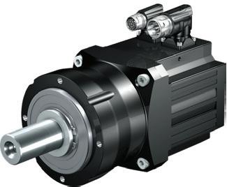
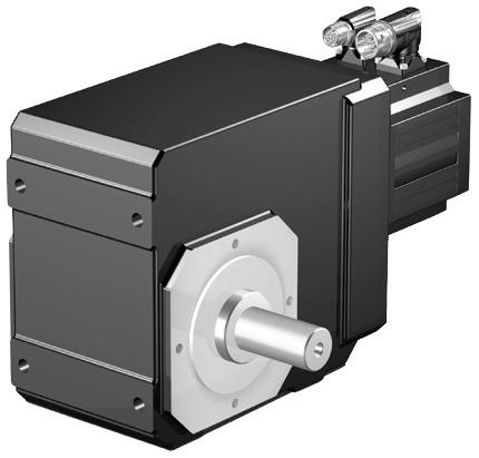
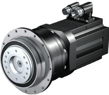
From intake to outtake and everything in between, STOBER has the products needed to optimize your application.Our breadth of knowledge and breadth of product means you can trust us to provide the ultimate solution.


Rahul Garg, vice president, industrial machinery, Siemens Digital Industries Software: Software-defined automation builds on existing IT and network infrastructure in factories and plants by extending and enhancing capabilities already in place. This is where we rely on existing ethernet infrastructure to add more of IT/OT convergence capabilities, cloud infrastructure/cloud platforms when deploying automation software and utilizing existing IT infrastructure for hosting virtual and existing data centers. Data analytics platforms can be added, as well as data integration enterprise platforms like enterprise resource planning (ERP) or manufacturing execution system (MES) software. Automation is a software layer atop a factory or plant’s IT and network infrastructure and provides greater flexibility and ability to leverage intelligence and minimize disruptions in those factories and plants.
Tell us about your company’s state-of-theart product that involves software-defined automation.
Rahul Garg, vice president, industrial machinery, Siemens Digital Industries Software: Industrial Operations X, our overarching portfolio for industrial production, features our Industrial Edge devices, our MOM portfolio, Insights Hub for IT/OT convergence, Simatic AX and Opcenter X (Figure 3). Industrial Operations X is based on four pillars: software-defined automation; data-driven production; modular operations; and industrial ecosystem. Industrial Edge is a key enabler for software-defined automation.
Thomas Kuckhoff, product manager, core technologies, Omron Automation Americas : The Omron Sysmac automation platform is at the very core of Omron software-defined automation. This all-in-one automation platform uses globally open industrial protocols on controllers, such as the NX102, and integrated development environments, such as Sysmac Studio, to design, commission and scale robust automation.
Omron Sysmac Studio embodies software-defined automation through its ability to integrate with mechanical design software, such as SolidWorks, Autodesk and ePlan; its connectivity to digital twin simulation environments with universal scene description (USD) output formats; and its quick programming with globally open industrial proto -
cols such as IO-Link, EtherCAT, Fail Safe over EtherCAT, CIP Safety, and EtherNet/IP. Omron NX502 controls logic with a quad core CPU and manages data as standard with OPC UA, MQTT and SQL connectivity out of the box.
Ken Crawford, senior director of automation, Weidmuller USA : Our latest SDA-based product is our M series of programmable automation controllers (PACs). At the heart of these multi-core controllers is a open architected operating system we call u-OS. U-OS is a hardened Linux-based operating system (OS) that utilizes portainer.io to support containerization allowing users to install and run their third-party applications including Inductive Automation’s ignition platform. The ability to install and run your control applications alongside our core controller capability of CoDeSys allows users to customize the controller with the features they need to complete the control system.
Michael Kleiner, VP of edge AI solutions, OnLogic: The backbone of software defined automation is really the computing infrastructure. What we bring to the table is a range of super reliable, high-performance industrialgrade computers—things like our industrial and rugged PCs, panel PCs and edge servers. These are the workhorses that run the software doing all the SDA heavy lifting.
Mark Collins, senior engineer, Mazak : Mazak has a long history of pioneering software-driven automation, starting in 1981 with the introduction of Mazatrol, one of the world’s first conversational CNC controls. This innovation allowed operators to program CNC machines using user-friendly, graphical commands rather than complex G-code, significantly enhancing efficiency on the shop floor. In 1998, Mazak continued to lead by integrating PC technology directly into our CNC controls with the launch of the Fusion CNC, bringing advanced computing capabilities to the manufacturing floor.
Mazak remains at the forefront of software-defined automation (SDA) with our industry-leading SmoothAi control. SDA refers to the concept where automation logic, monitoring and management are driven primarily by software, rather than being hard-coded into hardware. This approach provides unmatched flexibility, enabling rapid adjustments to machining parameters, seamless integration with other factory systems and remote monitoring capabilities.


Mazaks SmoothAi control exemplifies this philosophy. Mazatrol SmoothAi is an intuitive, software-driven programming interface that accelerates setup and programming. Smooth Project Manager is a centralized software solution for managing machining programs and configurations. Smooth CamAi is an advanced CAD/CAM integration for rapid part programming. Digital twin integration enables operators to simulate and optimize machining operations virtually before execution.
Sarah McGhee, product owner, Simatic AX, Siemens: At Siemens, we offer a range of tools to support users in adopting software-defined automation principles. One of our standout products is Simatic AX, an innovative engineering tool for PLCs that reconfigures the popular Visual Studio Code environment to meet the unique needs of the automation space. By leveraging a state-of-the-art IT environment, Simatic AX enables engineers to use familiar tools and methodologies in their automation programming. This approach not only reduces the learning curve, but also fosters collaboration between software and automation engineers. Simatic AX facilitates seamless integration with existing IT systems because it was developed with these sorts of systems in mind from the outset. It provides simple source control management, a built-in unit testing framework and smooth visualization into continuous integration pipelines, enhancing the overall efficiency and effectiveness of automation projects.


by Anna Townshend, managing editor


LADDER LOGIC MAY STILL REIGN supreme in the world of programmable logic controller (PLC) programming, but the full story is far more dynamic. As manufacturing systems grow more complex and connected, and as the workforce evolves, many machine builders and system integrators are rethinking how they write controls code. While ladder diagram (LD) remains dominant for its readability, ease of troubleshooting and deep roots in electrical engineering, other IEC 61131-3 programming languages—like structured text (ST), function block diagram (FBD) and sequential function chart (SFC)—are increasingly being adopted to meet the demands of data-heavy applications, advanced motion control and scalable system design.

Why ladder logic is still PLC programming king Ladder diagram has long held the crown as king of the IEC 61131-3 programming languages, and for good reason. Its electrical schematic-style visuals and straightforward logic have long made it the go-to language for control systems using programmable logic controllers, especially in North America.
Familiarity holds some staying power for LD, but it remains a practical choice for machine builders and system integrators who prioritize ease of maintenance.


LD is the backbone of industrial controls, but ST is a rising star, especially among younger engineers and software-savvy startups and for applications involving data manipulation, modularity and integration with modern technology and design tools. In many cases multi-language programming strategies are the key to clarity, functionality and future-proo ng.

Ladder logic forms the bulk of code for most customer software at Dynamic Motion Control (DMC). “It’s familiar and easy to troubleshoot for the majority of the industry,” says Patrick Smith, senior project engineer at DMC, a CSIAcerti ed system integrator, who has worked with manufacturers of all sizes since 1996.
Unless an original equipment manufacturer (OEM) plans to own the long-term maintenance of a machine or is selling its aftermarket service to end users with the machines, it’s essential to consider the skill set of the end user and the maintenance techs’ abilities.


Most maintenance teams that DMC works with are comfortable with LD, with some experience working with other languages. “DMC always provides the full source code to customers, allowing them to make their own changes and more easily troubleshoot, so taking the needs of their maintenance team into account is a key part of our programming approach,” says Smith, who notes it makes customers happy and saves middle-of-the-night phone calls if a machine stops working.
“Ladder is typically used for applications that involve discrete logic control, such as turning a valve on or off or programming a state machine that involves a sequence of operations,” says Imran Mohamed, motion control application engineer at Yaskawa America. “Automation tasks demand deterministic execution, real-time control and robust safety functions. IEC 61131-3 languages provide the clear and structured approach that is essential for these requirements. It’s not uncommon for safety logic to be written exclusively in ladder diagram for this reason.”
The visual of LD represents the electrical ow or schematic, so it’s a way to truly visualize the system. “A picture is worth a thousand words, so the ladder diagram has all the boxes and every representation of the electrical ow,” says Hoat Phung, senior application engineer at ABB. Many younger engineers come out of college with experience in languages like Python, but industrial customers still look to LD for simplicity, largely for ease of maintenance.
and version control are needed. With all that involved, it’s time to pause and evaluate which way is best for everyone to interact with the code.
“How does this PLC integrate into the entire ecosystem?” asks Kuckhoff. “What’s the complexity of this program? What’s this skill set of the team that’s going to be, of course, developing it, but primarily the maintenance team? And when it comes to that maintenance and those production engineers, what also are they familiar with?”
Newer programming tools and methods are also altering how engineers use LD. “LD is often considered easier to read and troubleshoot, though it may not scale as ef ciently as other languages. However, modern programming features such as labels, label groups, program organization units (POUs), and function blocks make it possible to structure and scale applications effectively, even when using LD,” says Tim Hider, industry marketing manager for smart manufacturing and digital solutions at Mitsubishi Electric Automation.
Instruction list is no longer part of IEC 61131-3, but ladder diagram, structured text, sequential function chart and function block diagram are being explored in new ways
“That visual nature is really nice and especially good for when you start playing back recorded data, where you can start to see ‘this is normally open, and it’s closed, or ‘this is normally closed, and it’s open,’” says Thomas Kuckhoff, senior product manager at Omron Automation. “It can help people troubleshoot really nicely.”
The choice of programming language can depend on how the PLC is being used in the application. “You’ll see some PLCs that are locked away behind a ton of rewalls, a separate network,” explains Kuckhoff. “No one touches it for years, and it’s doing the same thing all the time. But then you see some that are not on open networks, but larger factory networks that are required to comply with strict cybersecurity requirements.” This means updates
The industrial workforce is also changing, as younger engineers are bringing new skill sets to controls, at the same time as industry is embracing new technology, which is often influenced by the software world and text-based languages like structured text. “It is also important to know your audience,” says Casey Taylor, software product manager at Beckhoff Automation. “Who will need to read and support your code? What will be the easiest for them to understand? Don’t assume this will always be ladder. More of the workforce has been exposed to textbased programming of various types than ever before, and this shift makes them more comfortable with a wider range of languages.”
Taylor also reminds programmers not to forget about code management. Tools for version control are often built around text-based languages. Ultimately, Beckhoff sees the human-machine interface (HMI) as the best diagnostic tool for troubleshooting and maintenance of complex systems. “This is the rst and best place for maintenance teams to troubleshoot a system. If you can avoid having maintenance staff get into the code, you should. That said, the programming language inside the system will matter if changes are made in the future,” Taylor says.

“The choice of programming language also relies on the OEM’s support model,” explains Mohamed. “Some OEMs expect the end user to take full ownership of the machine’s source code and modify the program in the field as needed. However, not all OEMs or end users operate this way. In some cases, OEMs retain ownership of the source code and version control to ensure consistency across multiple plants operating in different geographic locations.”
The more complex the machine, the less the knowledge of the maintenance staff matters, Mohamed says, and less of that work may be done by maintenance crews in the future. “Even if a maintenance technician is familiar with a programming language, it doesn’t necessarily mean they understand how the software works,” Mohamed explains. “There is always a tradeoff between the risks and outcomes associated with allowing code edits on a production line. It’s the responsibility of the developer to carefully assess these risks and outcomes before committing to a particular language for a project.”
While ladder diagram reigns supreme among IEC 61131-3 languages, especially in the United States, in part due to its wide use and recognition, structured text is finding more room in industrial applications. ST is also more widely used in Germany and across Europe and Asia.
A growing number of engineers and integrators everywhere are making the case for ST, particularly for applications that demand more complex data handling and modularity at scale. LD won’t be replaced anytime soon, but ST is gaining momentum, helping engineers take on more software-centric tasks and embrace flexibility for array manipulation, loop and algorithms.
As an integrator, DMC prioritizes programming that is accessible and modifiable by its customers. “As such, we typically default to ladder logic, as it’s the industry standard in our main service area of the United States,” says Smith. “We then identify any logic that would be best served by structured text. In particular, we focus on logic that either would be excessively hard to read in ladder or is self-contained enough that it should not have to be frequently investigated as part of troubleshooting.” DMC uses ST for functionality that leverages its strengths, such as working with arrays and other complex structures.
ST shines for data handling. “It can be written compactly, which is helpful when working with a large amount of data,” explains Smith. “It has built-in support for control structures like for loops that make working with large datasets, such as arrays, much easier.” Because it is text-based, programmers can more easily use other development tools like integrated development environments (IDEs) to quickly generate large amounts of repetitive code.
“Over time, structured text is seeing more usage due to how flexible it is, and how it can integrate with other tools,” Smith continues. “In particular, startup companies that are often coming from a traditional tech background usually prefer structured text, as it looks more familiar and can better integrate with tools they are experienced with.”
Structured text is better suited for implementing loops, algorithms and other computationally demanding tasks,” agrees Yaskawa’s Mohamed. “Among the IEC 61131-3 programming languages, structured text offers the greatest flexibility for data-handling tasks, particularly when performing operations such as array manipulation and nested loops capabilities that are essential for data parsing and to establish communication interfaces,” he explains.
An array is a powerful type of data structure, used to store and manage similar types of data, such as sensor readings or status flags. An array is a structured list of elements, all the same data type, organized by index. Think of a row of mailboxes, each one numbered and holding a specific piece of mail, or value. Arrays are efficient for data handling because they manage multiple inputs or outputs of the same data type and store a history of readings.
“Arrays are best handled through structured text,” says Ken Crawford, senior director of automation at Weidmuller. “The least capable data-handling language would be ladder.”
In ST, arrays can simplify repetitive logic and enable more dynamic programming. The indexes can be variables,

so arrays support flexible logic, which is great for test sequences. Arrays also support modular programming and can handle structured, repeatable and dynamic data.
Beckhoff’s Taylor says it’s important to provide the option to program in all languages of the IEC standard, but ST is the most commonly used language among Beckhoff’s customer base. “Once a programmer learns how to create code in structured text, it typically becomes the language of choice,” Taylor says. “Other languages do have their strengths depending on the use case.”
Of the IEC 61131-3 programming languages, ladder diagram and structured text are the most popular, but some of the others still have a place in certain applications. One programming language rarely fits all, and, while some machine builders and system integrators stick to a single language for consistency, other languages might offer benefits for certain applications, and, ultimately, dynamic industrial automation might need a combination of languages to find the best code.
“Function block diagram is well-suited for device control logic, as the arrangement of inputs and outputs makes it compact and easy to read,” says DMC’s Smith. “Having the inputs, outputs, commands and interlocks for a device connected in FBD makes it easier to follow the flow of logic.”
Some of Beckhoff’s customers choose to mix standards. “We allow you to choose a language that’s unique to each function block, method or action,” Taylor says. “In short, I think ladder is good for chains of Boolean logic. Function block diagram works well for axis control and other similar scenarios. Sequential function chart is great for state control. Instruction list is usually not beneficial with modern systems,” he adds.
Sequential function chart, as the name suggests, is good for processes that follow a defined sequence. “However, customers may prefer to implement these sequences in ladder logic, as it is more familiar to many programmers,” Smith says. SFC is great for defining sequence control logic. “The built-in tools and graphical view of SFC make it easy to trace the sequence steps and transitions, as well as step through the sequence when needed,” he adds.
DMC avoids new programming in instruction list (IL) and only uses it on legacy systems when necessary. “Without a lot of experience, it’s difficult to work with, and the lower-
level functions it offers are rarely needed,” Smith says.
Instruction list was removed from Edition 4 of the IEC 61131-3 standard, which was published in May 2025.
If customers have specific language requirements, DMC will try to follow those but may recommend changes based on the difficulty of implementing that code.
“We see mostly function block diagram, structured text and ladder diagram in use,” says Matthias Pohl, global marketing manager of efficient engineering in automation and TIA Portal at Siemens. “Ladder diagram and function block diagram are most prevalent for ease of use and visualization, while structured text is mostly used for complex and modern automation needs. Many teams use a combination of languages, often within the same project, to play to their respective strengths.”
Aaron Dahlen, applications engineer at DigiKey, says the choice of programming language is as much about the choice of programmable logic controller as it is about language.
“Purchasing trends suggest that the market is diverse, with no single standout PLC; there are many PLCs to match the unique applications,” explains Dahlen. “In fact, DigiKey continues to onboard new PLC manufacturers. This diversity is reflected in the programming languages used in PLCs. Some of the smaller PLCs and programmable relays are programmed in FB with a dialect of SFC.”
Larger PLCs, Dahlen continues, tend to have more flexibility with full implementation of three to five IEC standards, while still other PLCs and edge controllers may be programmed in high-level languages, such as Python or MathWorks’ MatLab.
As machine complexity grows, many engineers are moving beyond a one-language-fits-all approach to PLC programming. The sweet spot seems to be a combination of IEC 61331-3 programming languages to best suit the application and the end user.
“Data handling is influenced by user preference,” says Mitsubishi Electric’s Hider. “Structured text is generally favored for mathematical operations and complex data manipulation. However, many PLCs with legacy support include custom functions that enable efficient handling of 16bit data using ladder diagram. Block moves and FIFO tables make LD a viable option for straightforward data handling. Additionally, some manufacturers offer the ability to embed ST code inline within LD rungs, combining the power of ST with the readability and troubleshooting ease of LD.”
Security, flexibility, readability, scalability
While LD may still dominate PLC code, more controls engineers are finding reasons, such as security issues, to incorporate other languages. “In some cases, we want to use structured text, but we want to have a function block that is locked down with a password that no one can get in because the end user has intellectual property (IP) that they really don’t want anyone with a thumb drive stealing,” says Omron’s Kuckhoff, who also points to the automotive industry’s use of LD and sequential function chart as an example of multi-language programming. “Not only is their automation getting more complex and integrated more into enterprise resource planning (ERP) systems, but also there is a huge amount of flexibility that the line is expected to do, whether it’s internal combustion and plug-in hybrid or just an electric vehicle,” he adds. This means when maintenance tries to assess a machine issue, it’s complicated because
it was, for example, working fine on the last shift while making a different drive train.
“That’s where we’re seeing ladder logic pop up a little bit,” Kuckhoff says. “We’re seeing these chunks of the program displayed in a much more visual format, so a maintenance person could better monitor how a machine is running through its steps, not by monitoring all the rungs of logic, but looking at it from a flow chart type of situation. That’s allowed teams to get to that root cause much more quickly.”
SFC provides a visual flow chart of machine function that can allow someone who didn’t write the code to work through the steps and figure out where the program is hung up.
Ladder is often championed for its readability, but textbased languages are often more flexible and easier to scale. “The simplest answer of making it all ladder logic often results in excessively verbose programs that are just as hard to read as another language,” says DMC’s Smith.
By Tobey Strauch, contributing editor
Semiconductors and software make up the internals of the programmable logic controller. The line for computing power in the PLC has been blurred for a while, and most are more computers than PLCs, but we keep calling them PLCs. This evolution is possible because of advancements in semiconductors and software development. Add the onset of open protocols and smart edge devices for the field, and control systems have no boundaries.
The framework of sensors, actuators, controllers and communications interfaces is allowing control systems to expand in industrial and civic settings. Artificial intelligence adds another layer.
Artificial intelligence allows for adaptive control. Traditionally we do this with a proportional-integral-derivative (PID) loop. ABB has introduced diagnostics in its expanded product, Ability. Ability is an artificial intelligence system in its PLC. ABB allows for management of assets and transformers and gives feedback to a centralized location.
Genix Industrial IoT and AI Suite is used by ABB to look at data convergence and AI-driven insights, as well as scalability. These types of monitoring systems are getting more popular across many platforms, but people need to understand that the application of AI in a PLC may be slow. Why? It’s easier to deploy it with chemical changes and 24-hour type process
engineering or energy monitoring than actual assembly. It is also not automatic. People still must interface and categorize so the system can learn upsets and normal operations.
The advantage of Genix APM Copilot is that there is a naturallanguage interface and real-time decision support. Can we take real-time decision support and adapt it to a PID interface? ABB says it can converse with the Genix system based on the naturallanguage interface and the real-time decision support, but does it matter if the system cannot be made when an upset occurs?
The response is to set up data-driven modeling based on inputs. Thus, the PID changes cannot just happen in an artificial intelligence environment. Why? The machine must learn, and the disturbances must be learned. This setup is called detection and classification. The next part is classification of faults based on sensor faults, process anomalies or external disruptions. Can you tell the system enough information to support it to classify sensor failure or wiring fault or to distinguish between a process disruption or an operator error? In summary, artificial intelligence may be used to identify problems, classify the disturbances and then predict upsets based on trend models.
If we build up this data, then the system may be able to predict future upsets based on trending. Humans still must classify the upsets and determine what data to use. Once the data is decided
The function block is a core concept in the IEC 61131-3 standard and used in multiple languages, namely FBD and ST. A function block is essentially a chunk of PLC programming logic. It’s modular and reusable, and it encapsulates a specific function. Function blocks are useful for time-based or sequential operations because they remember values between the scans.
A user-defined function block (UDFB) can be constructed in the language of choice, explains DigiKey’s Dahlen. “Then stitch them together in the top-level program using ladder logic,” he says.
Encapsulating code into function blocks enables scaling with reusable code. “Such function blocks may have an outward representation intended for FBD but contain flexible ST code inside,” says Yaskawa’s Mohamed. “The use of modular function blocks can also assist with the protection of intellectual property. This is very important for OEMs and system integrators who want to safeguard their proprietary
algorithms or trade secrets from scrutiny by the end users or other competitors. My approach is to use ladder diagram or sequential function chart for high-level machine control and state machines, where readability and clarity are essential. For reusable and scalable logic, I prefer using structured text or function blocks. This balanced approach has consistently worked well for me and my customers, ensuring the system remains accessible to technicians while also being robust, scalable and efficient for developers.”
Sara McGhee, product owner of Simatic AX at Siemens, says its customers also use a mix of languages. “In the United States, you’re going to see some kind of ladder or a graphical representation of language at least somewhere in the program,” she says. “That’s really important to customers to be able to have that visibility.”
upon, then the machine could be set up to use adaptive PID tuning. Adaptive PID tuning means setting up trends to change the proportional, integral or derivative based on an input to the PLC, a comparison between current real-time data and trend models and then what outcome is expected. The system cannot do this in a vacuum. It requires reinforcement learning and model predictive control integration. What if there is data? What about timing? What if the computer adjusts and there is a major swing in a loop control? For those instances, the program still must be set to work within fault strategies and fallback based on anomalies. Why? Automatic changes could hurt equipment.
The other is the option to produce a digital twin or set up test routines with the source data and see if you can predict output based on testing software and the process loop. What does this mean? This means coding the system that is in place and using shadow loops with the input data. Trend the operational data alongside the test data and then make small adjustments. This is labor-intensive and takes thought and planning, and probably a modern PLC. What would be next? Optimization.
Genetic algorithms, particle swarm optimization or other types of optimization might be used to create real-time PID adjustments. How does this differ from a current PID loop adjustment? It really does not, except maybe it gives more versatility to recognize upsets and set adjustments sooner.
It still requires human forethought to program the instance so that the system might decide. How people are doing that on the PLC level is beginning with monitoring upsets and adaptive PID loops. It’s confusing because traditional controls engineers may look at current PID loops as adaptive. The output of the PID is the setpoint of the control valve or the temperature change, correct? The output is changed based on the current value not meeting the setpoint, and the PID adapts.
Artificial-intelligence folks still classify that as a linear response and its based-on linearization of system feedback. Artificial intelligence will allow adapting to nonlinear real-time feedback and may propose different responses.
Traditional PID control is fixed, does not learn and is reactive. Case in point: a drive will try to keep speed if it loses reference and might run away. Most of the time, there are other parameters to eliminate runaway conditions. Artificial intelligence poses new ideas to respond to complex changes, and it does not always have to be linear.
How is it being used in reality? ABB is using ABB Ability OptimE and Marine Pilot Control to optimize propulsion efficiency and reduce emissions using vessel speed and toe angle. Genix APM Copilot and Snowflake AI Cloud are being used to allow manufacturers to ask asset health questions and unify data to optimize pricing, inventory and distribution.
However, she is seeing more customers gravitate toward text-based languages. “What we see globally, there’s more adoption of text-based languages for PLC programming overall,” she adds.
The next generation is also leaning into more text-based languages, she says, driven by the rise of computer engineers in the market. And the advances of software programming are beginning to influence the automation space. “While text-based languages aren’t new, they’re more widely accepted in the automation space,” McGhee says.
In general, designers look toward text-based languages for programs that have more complexity. “You can get something up and running really quickly with graphical languages,” says McGhee. “But, as your systems get more complex, it may take a lot longer to figure out how to do something in a graphical language and do it in a way that makes sense.” More complex operations with data intake or manipulation are often easier with text-based languages.
With machine builders, Siemens has many discussions around why text-based languages might work in some situations but not others, McGhee says. “That’s why the blend is really key,” she explains. “Maybe you have a library centered around text-based language or structured text, where you’re doing those data operations. Then you’re able to pull that library in some function block into the rest of your program that is maybe more of a graphical representation. At a lower level, at certain points, it might be structured text, but from a high level, those engineers that service the machines have the ability to see what’s going on.”
Claudia Dürr, global marketing manager at Siemens, seconds this strategy at Siemens for combining programming languages. “It is common to use a mixed-language strategy: Combine ladder diagram or function block diagram for the straightforward, or frequently troubleshoot logic—interlocks, alarms, simple sequences—with structured text for complex processing, data handling or algorithms. This leverages the high readability of graphical languages where needed and the scalability/reusability advantages of ST where beneficial,” she says.
Text-based languages can provide a lot of flexibility and power, but it comes with some added responsibility, McGhee says. “Now with the adoption of more text-based languages and software principles, you see more and more people adopting some of the quality standards that they
have in place, and there’s a lot of testing that goes into software development that we don’t see as much in the forefront of the automation space.”
For automation, this means adopting that test mentality, for example, in terms of library development, McGhee says. “If you’re developing that library block, ideally, you’re testing it,” she explains. “You’re checking the quality of that before ever inputting that in the program.”
If something goes wrong in the library block, then the service person would have to go into the library. “Then, they’re in the text language, and then they don’t know how to debug it because it’s not as easy to understand as a graphical language.”
PLC programming language choice influenced by region, industry and workforce
Region can play a role in choice of programming language. Anecdotally, structured text is more popular in Europe, whereas ladder diagram rules in the United States. “Companies on the west coast near tech hubs like San Francisco often prefer structured text. Within industries, pharmaceutical and food and beverage are more likely to use function block diagram, as that was often the language of choice in distributed control system (DCS) and process solutions for those industries,” says DMC’s Smith.
Ladder diagram remains strong in the central and Midwest regions of the United States, particularly in the rust belt, among automotive manufacturers. “There is a noticeable shift toward increased use of ST and FBD,” says Mitsubishi Electric’s Hider. “Coastal regions, home to industries like semiconductors, data centers and pharmaceuticals, tend to favor ST due to the workforce’s familiarity with high-level programming languages. Function block diagram is also gaining popularity, particularly among OEMs involved in motion control, as it provides a comprehensive visual overview of servo operations on a single screen.”
Engineering disciplines can sometimes dictate a programming-language preference for programmable logic controllers, as well.
“Programmers with an electrical engineering background often tend to prefer ladder diagram, as it closely resembles electrical schematics that contain contacts, relays and coils++,” says Yaskawa’s Mohamed. “In contrast, those with a computer engineering background typically prefer structured text, due to its similarity to high-level programming languages like C or C.”
ABB’s Phung says ladder diagram is still dominant with the company’s U.S.-based customers. “But with the younger engineers moving into this field, they have a tendency to use a little bit more of a mixture of structured text and function block diagram,” he adds.
Structured text is dominant in Germany and Europe, says Phung, “but in the United States, we still have electricians in the factories maintaining the machinery, so ladder diagram is still the backbone because that’s what they are familiar with.”
Michael Guckes, product manager at Hottinger Brüel & Kjær (HBK), a machine builder headquartered in Virum, Denmark, says the company’s software developers prefer modern object-oriented structured text. Largely, the company’s younger engineers prefer object-oriented languages.
HBK focuses on test-and-measurement machines and systems, which often require precise timing, data logging and signal conditioning. To do this, HBK uses hardware that interfaces with operational technology (OT) and information technology (IT) assets.
IEC 61131-3 languages support real-time controls on the OT side. Ethernet and TCP/IP are used for data logging and analysis by IT.
HBK production engineers set up and program its calibration machines, and a separate engineering department, called system solutions, programs code for customers. It sees a growing need for more advanced or modular programming approaches, like ST, again, strongly supported by young engineers, Guckes says.
Most of the controls systems for HBK machines are “sequence-driven,” Guckes says. “They follow the calibration-procedure for our sensors. In case of an unexpected event or failure, a watchdog function saves the machines and sensors from damage.”
For high-precision test environments, more libraries dedicated to measuring tasks would be helpful for IEC 61131-3 programming languages, he adds, taking into account the needs of adjusting and managing measurement amplifiers. “It would help a lot to offer databases to handle bigger amounts of measurement data,” Guckes says.
In a world where ladder logic is still dominant, texted-based programing languages like structured text are gaining ground, especially as industrial automation adopts modern software practices such as version control, continuous
integration/continuous development (CI/CD) pipelines and artificial intelligence (AI).
Developers are increasingly asking whether the industrial world can catch up to the modern tech stack without sacrificing the stability and determinism that make programmable logic controllers so reliable.
How might higher-level programing languages and version-control tools like Python, C# and GitHub integrate into traditional controls environments? While the IEC 61131-3 languages still form the foundation of control logic, the case for expanding beyond them, or at least bridging the gap, is growing stronger.
The tech industry has developed many design tools, which largely use text-based languages, and DMC’s Smith thinks they will inevitably make it into the world of machine controls. “I expect to see structured text continue to gain popularity,” Smith predicts. “In addition, the ability to represent languages like ladder logic with a text equivalent is becoming more developed.” He highlights some of the modern development tools driving language choice, including:
• powerful and extensible text-based integrated development environments such as Visual Studio Code
• integration with version control platforms like Git
• utilizing CI/CD pipelines and DevOp workflows.
“While several companies are working to bring these tools to the controls world and its unique languages, the plethora of easily accessible tools will likely continue to push the industry toward structured text,” DMC’s Smith says.
As far as movement toward higher-level languages, such as Python or C# or other model-based design, Smith could see it happening some day, due to the popularity of those languages, but not any time soon, for a number of reasons. Namely, IEC languages have strong industry support and PLC products that support them. Right now, very few higher-level languages are able to run on a PLC’s CPU without significant modifications by the PLC vendor.
“So, not only do the vendors give up control over the language features available, but they also have to do extra work in making the language capable of running properly,” Smith says. “The alternative would be shifting PLCs to sharing more architecture with PCs or common embedded controllers, but that would be a fairly radical paradigm shift and still results in the PLC vendors giving up control over parts of their hardware and software.” PLC vendors might also disincentive these languages as they could ultimately
make it easier for programmers to transition between vendors, instead of standardizing on one.
Another problem with high-level languages for controls programming is that they receive frequent updates and improvements. “Since the controls world generally prefers stability over the cutting edge, the PLC implementations of these languages would likely not keep up with the language release cadence,” Smith explains. “This would lead to situations where PLC Vendor A supports Python 3.11, while Vendor B supports Python 3.9, and that doesn’t even begin to get into variations between controllers from the same vendor. Since these language versions can often bring significant changes, it would not improve the portability of the language at all.”
Higher-level languages are also much harder to maintain and troubleshoot. “Higher-level languages typically require more familiarity and bring their own set of tools and best practices for troubleshooting,” Smith says. “Transitioning to higher-level languages would likely require companies to provide thorough training for their maintenance teams or hiring programmers who know these languages well.”
On the downside, these programmers are likely more expensive, he adds, and less familiar with electrical and mechanical problems that maintenance teams face.
“In addition, effective troubleshooting of higher-level languages would likely require adopting DevOps strategies, such as maintaining development and testing environments, or being able to replicate a production environment when debugging,” Smith says. Software-based PLCs and digital
twins are starting to bridge this gap, but industry-wide support has a long way to go, he adds.
AI is coming for PLC programming, but not how you think PLC programming won’t change dramatically anytime soon, but new technologies are having an impact, explains Mitsubishi Electric’s Hider. “While higher-level tools like Python and C# are gaining attention, IEC 61131-3 languages are unlikely to be fully replaced in the near future,” he says. “The integration of generative artificial intelligence into development tools is increasing the popularity of structured text, as it is easier for AI to generate and interpret compared to more visual languages like ladder diagram or function block diagram. Additionally, open-source communities often provide well-tested Python snippets that can complement ST. However, the industrial nature of PLCs—designed to last for decades— means that IEC languages, which have also been industrialized, will remain relevant for a long time.”
Siemens’ McGhee does see a place for higher level languages in industry. “I know we have applications where we’re doing fast communication between the PLC and something running one of those high-level languages, whether it be an IPC or some other kind of computer,” she says. However, she doesn’t see standard PLC programming go away entirely. “I think PLCs are going to become more powerful and then maybe some other languages could be leveraged,” she predicts.
In the dawn of industrial artificial intelligence, text-based languages might also get a leg up. “It’s a lot easier to train a model on a text-
based language, rather than a graphical one,” McGhee says. AI is also much better at deciphering what the structured text is programmed to do. “When we think of who’s servicing and maintaining these machines, if you weren’t the one to write the code, to be able to feed that into an AI model and have it kick out at least an idea of what is going on in that program is going to be huge,” she says.
Siemens’ Dürr says even IEC languages are expected to evolve. “Structured text is already serving as a bridge between traditional control programming and modern software development practices,” she says. “In parallel, higher-level programming languages are increasingly being used alongside IEC 61131-3 languages, especially for tasks such as data analytics. Applications at the edge or in the cloud, as well as those involving simulation or digital twins, often benefit from the flexibility and power of higher-level languages. As a result, a hybrid approach is emerging—preserving the stability of proven PLC languages while leveraging modern software paradigms where appropriate.”
DigiKey’s Dahlen says any shift toward different languages lies in the close relationship between the PLC and the microcontroller. A microcontroller or microprocessor in a ruggedized protected environment is the core of a PLC. “Any shift away from the traditional PLC programming languages is a move toward the raw microcontroller or, in some systems, a move closer to the real-time operating system (RTOS) hooks running on top of a microprocessor,” Dahlen says.
The more real-time constraints that are added, the more complex the programming becomes, and indus-
trial safety adds another layer. “For example, the programmer may stick with the tried-and-true PLC program scan—get inputs, run the user’s program, set outputs and then perform housekeeping. While this process is baked into ladder logic, it is not inherent in higher-level tools. As a result, the programmer must construct the responsive code or purchase intellectual property to coordinate the program. They effectively trade the well-known safety of the IEC 61131-3 environment for a different abstraction layer that performs the same basic operation,” Dahlen says.
With the wide variety of equipment used across industrial automation, some applications may prefer higherlevel languages. Some users may also prefer non-native PLC software, such as a PLC capable of running MatLab. “This unique configuration is supported by the Raspberry Pi compute class of PLCs, such as the Kunbus,” he says.
Beckhoff’s Taylor says tools like source-control, usually Git, editor availability and more recently generative AI are also influencing the increasing support for text-based languages. Programmers that can bridge the gap between controls programming and other emerging technology could be a competitive edge in industrial automation. “When an engineer needs to work in both areas, there is a clear benefit when the tools are similar,” says Taylor. “It can also be beneficial when they can use the same source control, editor, compiler and other tools. As some automation software platforms have grown to encompass commonly used computer science standards, programmers should gravitate toward solutions that continue to expand
and directly incorporate these new technologies. The goal should be to provide as many high-value programming tools as possible and widen the pool of engineering talent that machine builders and system integrators can leverage.”
While higher-level languages are being used more in programming for machine control, Taylor doesn’t see IEC languages being replaced completely. “Some components of a system can be and often are written in these higher-level languages, but each language has inherent strengths and weaknesses,” he says. “The IEC languages, particularly structured text, give you access to the many strengths of object-ori-
ented programming while naturally avoiding things such as dynamic memory allocation, which should be used less often or at least carefully in a machine that needs to be deterministic and respond quickly.”
Yaskawa’s Mohamed agrees that PLCs are advancing, and higher-level languages will play a role. “PLCs are increasingly being designed to support new technologies by offering higher-level language support, such as Python and C++, alongside traditional IEC 61131-3 languages,” he says. “They also include advanced communication protocols like OPC UA, MQTT and REST APIs, which are well-suited for connectivity to cloud platforms and third-party applications.”


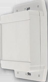


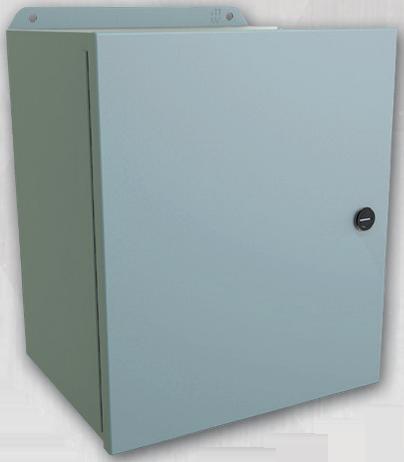


How object-oriented SCADA enables scalable, replicable industrial control systems
by Nestor Arria, Disruptive Automation Solutions
FOR DECADES, TRADITIONAL supervisory control and data acquisition (SCADA) systems based on flat tag structures have served their purpose. Yet, when facing complex, repetitive or large-scale projects, this architecture becomes a bottleneck—limiting efficiency, standardization, and scalability. Inspired by the principles of object-oriented programming (OOP), SCADA platforms now offer a more modular, intelligent and replicable approach. OOP concepts are being applied to SCADA design, and platforms from suppliers such as Aveva and Inductive Automation bring strategic advantages to the table.
Nature’s blueprint:
a living analogy for OOP
There is no better analogy for objectoriented programming than stem cells in nature. A stem cell encapsulates all the genetic information necessary to replicate and generate specialized cells (Figure 1).
In programming terms, a stem cell functions as a base class—defining attributes, behaviors and functions— capable of creating instances, or cells, that not only inherit characteristics, but also adapt dynamically based on environmental stimuli. This is polymorphism. And since all genetic information remains encapsulated within the cell without exposing internal details, we see encapsulation in action.
This paradigm translates clearly to industrial SCADA design, where platforms like Aveva System Platform al-
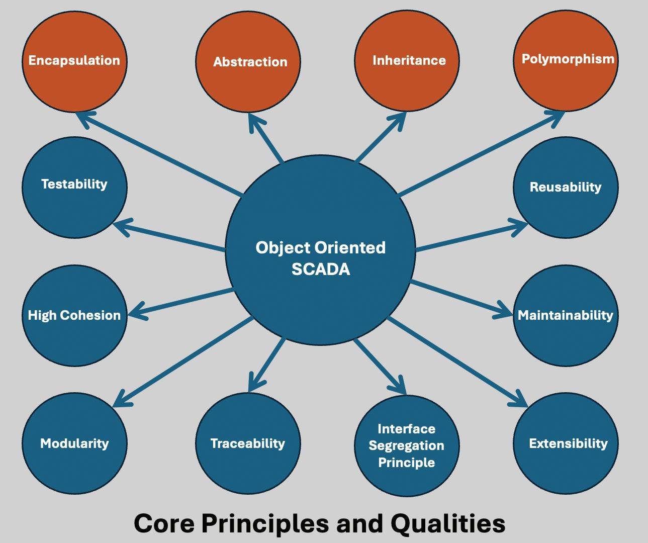
Figure 1: There is no better analogy for object-oriented programming than stem cells in nature. A stem cell encapsulates all the genetic information necessary to replicate and generate specialized cells
low engineers to model templates that encapsulate not only data structures and attributes, but also scripts, graphics, animations and alarm definitions. When properly designed, these templates allow for the creation of multiple object instances during engineering time, each sharing core behaviors yet capable of dynamic variation using contextual tags or reference inputs. This is the power of the object context, or the “Me” reference, within templates.
Fundamental requirements
Comprehensive, flexible template design: The base object must include standardized graphics, reusable scripts, indirect addressing mechanisms, parameterized behaviors, conditional visibility and logic. This requires mastery of scripting capabilities, such as ArchestrA Script, Python, C#, and a strong data architecture vision.
Structured standardization at the programmable logic controller (PLC) level: Data blocks—user defined types
(UDTs), add-on instructions (AOIs) or equivalents)—must follow similar object-oriented principles, encapsulating parameters, using consistent naming conventions and aligning semantically with SCADA objects.
This enables automatic binding using naming and structure conventions, reducing manual work and minimizing human error.
When true integration is achieved between PLC-based control systems and SCADA supervisory systems under an object-oriented architecture, we gain not just engineering efficiency, but system robustness, maintainability, and the ability to scale and replicate across multiple plants without compromising control or traceability.
Let’s revisit what a SCADA system fundamentally is: an industrial computing system designed to monitor, control and acquire real-time data from field equipment such as sensors, actuators and PLCs. Its mission is to ensure safe, efficient and continuous operation of complex systems. Typical SCADA components include:
• human-machine interface (HMI), which is a graphical representation of processes
• data acquisition server, which collects data from field devices
• historian, which stores data for analysis and traceability
• communications network, which links all system components, using Ethernet/IP, Modbus, OPC or other protocols
• PLC, which execute local process control logic
• core functions, such as real-time monitoring of process variables, including pressure, temperature, level and flow
• remote control of devices, such as valves, pumps or motors
OOP principles in SCADA—key translations
OOP Concept
Class
Object
SCADA Application Example
Object Template or UDT defining structure and logic
Instance of a template (e.g., Motor101, Valve3)
Attribute Tag or property (e.g., RunningStatus, Setpoint)
Method Embedded logic or scripting (e.g., alarm calculation)
Encapsulation Isolation of internal logic from external access
Inheritance Derived templates extending base behaviors (if supported)
Polymorphism Same interface, different behavior (e.g., valve types)
• alarm and event generation
• historical logging and trend analysis
• integration with the manufacturing execution system (MES) or enterprise resource planning (ERP) software and industrial protocols.
In early SCADA systems, the architecture focused on direct tag mapping, which was practical for small installations. For instance, building the interface for a compact oil battery may only require three or four screens and a handful of tags created manually. But in large-scale projects, such as a natural gas liquid (NGL) plant, the “spaghetti” of surface connections becomes unmanageable.
Think of the evolution this way: in small projects, you’re manually connecting hoses. In larger ones, you build underground conduits with predefined connection points for present and future modules. Objectoriented SCADA follows the latter approach, laying a structured foundation first—templates/UDTs— which dramatically accelerates tag creation and interface development later.
Before reaching object-oriented SCADA, platforms underwent significant transitions.
Tag-based SCADA, such as Wonderware InTouch, evolved into SuperTags—complex tag structures enabling more efficient licensing and improved UDT integration.
Indirect addressing revolutionized binding by allowing tag references via dynamic strings, enabling scriptbased creation and access of tag paths at runtime.
The quantum leap came with full OOP adoption: templates as encapsulated classes, with attribute areas for database/alarm integration, scripting engines for automation and graphical zones for visualization, selectable dynamically or manually.
Rockwell Automation’s PlantPAx architecture exemplifies this shift, now extended further through FactoryTalk Optix, which embraces a more refined object-oriented model, positioning it as a strong contender against Aveva and Inductive Automation’s Ignition.
A motor template might include:
• StartCmd (BOOL)
• RunningStatus (BOOL)
• SetpointSpeed (REAL)
• DisplayColor (STRING)
• IsRunning—an internal logic-driven attribute.
Instances such as Motor101, Motor102 share this logic but carry their own data. Benefits include:
• reusability—instantiate templates infinitely without redundant work
• maintainability—template-level changes propagate to all objects
• scalability—ideal for fleets of similar equipment
• modularity—each object is a selfcontained, testable unit
• time saving—templates accelerate configuration dramatically in large projects.
Platforms like Ignition, Aveva System Platform and FactoryTalk Optix fully support these principles, with OPC UA acting as a natural bridge due to its own object-oriented modeling of industrial nodes (Figure 2).
More features don’t make SCADA better. Modern systems prioritize architecture over accumulated functions. That means modularity, replicability, maintainability and resilience. Smart scaling through modularity allows:
• reusing logic and graphics without rewriting code
• centralizing control without duplicating it
• performing sweeping updates with minimal disruption.
A sustainable SCADA system:
• reduces technical debt and copypaste errors
• requires less maintenance effort
• simplifies training via clear object hierarchies
• adapts to growth without architectural redesign.
This results in lower operational
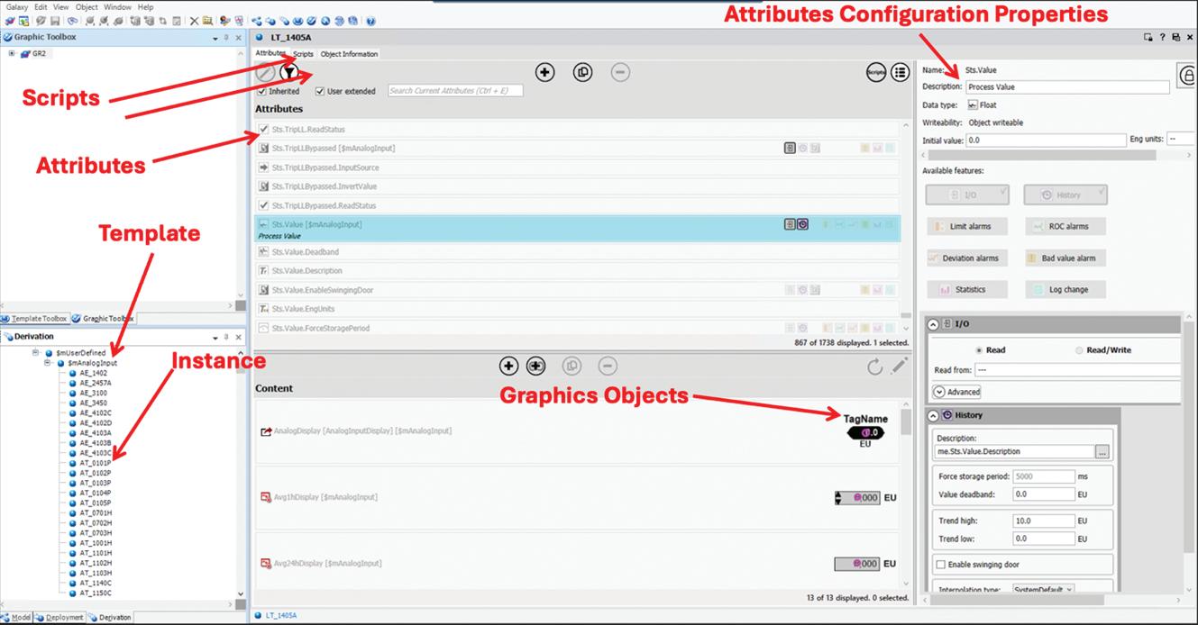
costs, better traceability and more robust systems.
OOP, ISA-88/95/101 standards and technologies like OPC UA or MQTT don’t complicate SCADA. They encapsulate complexity, providing clear, secure and structured interaction.
Thinking in terms of object-oriented SCADA means adopting a paradigm with a certain level of abstraction and applying it practically in projects, following the same principles of objectoriented programming in the design of templates—remember our stem cell. The creation of a class, or template, must be done carefully by linking the I/O attributes developed in the SCADA to our generic AOI with Rockwell Automation, function block (FB) with CoDeSys and Siemens), or derived function block (DFB) with Schneider Electric. In other words, the attributes of the template must be mapped to their equivalent data points in the PLC.
A robust scripting strategy should also be developed to automate
and semantically synchronize the instance names with the names of the UDTs in the PLC. When possible, graphical objects should be generated dynamically based on the signal type specified in the instance’s tag name.
If all this groundwork is wellexecuted, the project will accelerate by enabling faster instance creation with virtually zero errors, and this is the magic of applying the objectoriented paradigm. Standardization is the key to making all the pieces fit together seamlessly.

Nestor Arria is a senior automation engineer with more than 30 years of experience in the oil & gas industry across onshore and offshore projects in the Americas. He has delivered conference talks at U.S. events, such as OT SCADA CON, and at universities in Venezuela and Peru (IEEE) on topics related to process automation.. Contact him at narria@daswtx.com.
The AX8820 regenerative energy unit from Beckhoff is designed to enable wide-ranging machines and systems to feed power back into the grid, reducing wasted electricity and boosting sustainability. This module is compatible with the AX8000 multi-axis servo system, AX5000 digital compact servo drives and thirdparty devices. Using sinusoidal regeneration, the AX8820 prevents grid distortions. The AX8820 regenerative energy unit is designed for a nominal supply voltage of 400 to 480 Vac, output of 7 kW and a maximum dc link voltage of 848 Vdc. For effective energy management, the regenerative energy is initially stored in the dc link. The AX8820 feeds power back into the grid just before the overvoltage threshold of the connected devices is reached. Several AX8820 regenerative units can work in parallel to optimally adapt the regenerative power to the needs of the machine. Several Beckhoff technologies enhance the AX8820’s capabilities. The EtherCAT industrial Ethernet system supports extended parameterization and diagnostics to analyze regenerative energy. The online data can record the timing of machine processes to help determine if adjustments would increase efficiency. Motion Designer, a configuration toolset built into TwinCAT 3 automation software, calculates regenerative braking power in kWh for any Beckhoff motor-drive combination. TwinCAT Analytics measures and visualizes regenerative energy alongside other production metrics. TwinCAT Metrics can monitor drive performance by measuring the dc-link voltage. Beckhoff Automation / www.beckhoff.com
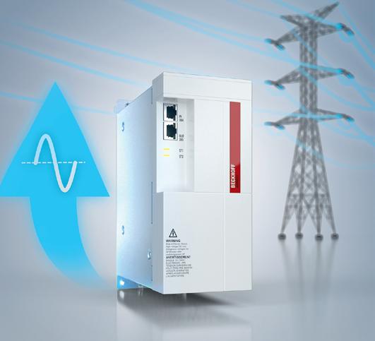
22.5 mm. PISA-M models can be integrated into either 12 V or 24 V systems without manual configuration with its automatic-voltage detection feature. PISA-M contains overcurrent and shortcircuit protection. In addition, PISA-M protects the connected power supply from overload. The push-in connectors on the front of the module allow for tool-less installation. It has two-color LEDs that show the status of each output channel in real-time and a button on each channel for on/off switching and resetting. Puls provides several variations of the PISA-M. The 4ADJ modules are adjustable, meaning each output channel can be set to the required current value from 1 A to 8 A. If a plug-and-play device with fixed currents is needed, PISA-M versions with fixed-output current settings, including 2 A, 4 A, 6 A, 8 A and NEC Class 2, are available. The PISA-M-4CL2 model provides four protected NEC Class 2 loads from a single power supply and automatically adjusts tripping current based on the system voltage. It delivers 3.75 A at 24 Vdc (90 W maximum) per channel and 4.85 A at 12 Vdc (58 W maximum) per channel.
Puls / www.pulspower.com
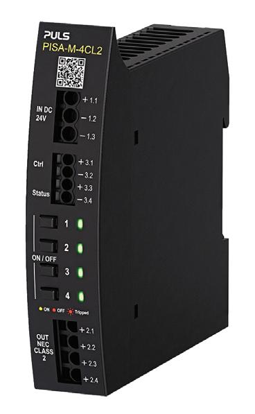
Puls PISA electronic circuit breakers (ECBs) with four channels are designed to create multiple lower-power circuits from a single power supply. PISA-M units have a width of
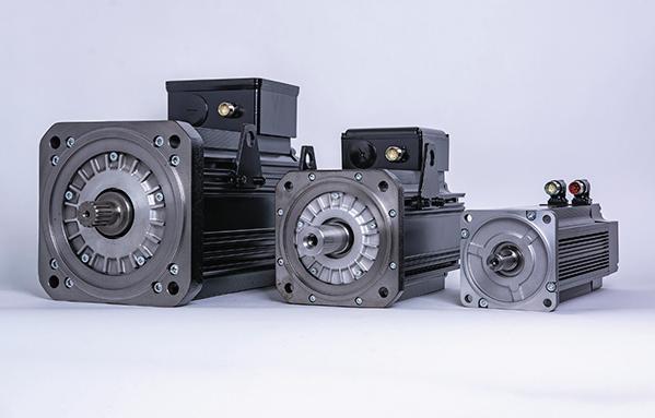
KEB America’s DL4 servo motors are designed to deliver high torque and precision in a compact design. They are designed for demanding industrial applications and offer options for cooling, protection and feedback systems. Available in multiple sizes with torque ratings ranging from 11 to 520 Nm, DL4 servo motors are designed to deliver performance for a range of large-power machinery.
KEB America / www.kebamerica.com
ABB Baldor-Reliance SP4 motors
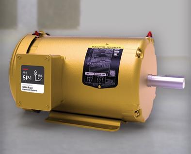
ABB’s SP4 technology meets the NEMA Super Premium efficiency level in a standard ac induction motor design operating across the line, independently of a variable speed drive. SP4 is designed for a more sustainable and efficient future driven by the need to reduce energy consumption. SP4 motors meet current U.S. Department of Energy efficiency standards, as well as anticipated Medium Electric Motor (MEM) regulations, which take effect on June 1, 2027, in the United States. These regulations mandate that motors up to 100 hp must maintain NEMA Premium efficiency, while motors between 100 and 250 hp must achieve NEMA Super Premium efficiency.
ABB / new.abb.com/motors-generators
Wieland Electric’s plug-and-play decentralized power
Podis is the modular, pluggable power distribution system. Featuring a flat cable and piercing-contact technology, podis is designed to enable tool-free installation and reconfiguration of power lines. The system supports power distribution up to 60 A and includes pre-assembled modules for lighting, conveyor and machine applications. Its decentralization is designed to eliminate complex wiring runs, simplify commissioning and ensure a scalable, future-proof power infrastructure.
Wieland Americas / www.wieland-americas.com
ABB ACS380 drive
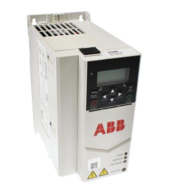
ABB’s ACS380 machinery drive supports precise motor control across asynchronous, permanent magnet and synchronous reluctance motors (0.25–22 kW). Available in single-phase (200–240 V) and three-phase (200–480 V) variants, it incorporates built-in braking chopper, common dc connection, safe torque off (SIL 3/PL e) and adaptive programming. Featuring preconfigured connectivity for Profibus, EtherCAT, CANopen, Profinet, Modbus TCP and EtherNet/IP, it
includes integrated electromagnetic-compatibility (EMC) filters (categories C2/C3/C4). The drive is IP20-rated and has coated boards. It can operate up to 60 °C with derating.
Galco / www.galco.com
Schneider Electric’s Altivar soft starter ATS490 range is designed for high-durability performance in process applications. The ATS490 range provides motor management and provides a holistic vision of the system. The ATS490 is designed to extend the equipment’s lifespan while minimizing downtime. It’s designed to withstand stress in order to avoid unplanned interruptions while certified cybersecurity features are desugbed ti enforce access control and integrity.
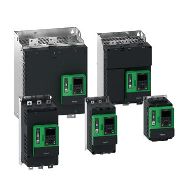
Schneider Electric / www.se.com
IDEC ez-Wheel Safety Wheel Drive combines a wheel, gearbox, motor, safety encoder and safety drive to streamline the integration of powered motion. The SWD is available in a light/medium SWD 125 model or a heavy-duty SWD 150 model both with a load supporting cast iron frame. A shockproof housing is rated IP66 to protect its internal electronics. For each model, two gear ratios are available, each with or without a parking brake. The SWD 125 supports a 250-kg vertical load and targets applications up to a ton. The SWD 150 supports a 700-kg vertical load and targets applications above a ton. Each SWD is connectorized for 24 Vdc power, safe input/output (I/O) signals, CANopen communication, USB, and brake functions. LEDs on-board the SWD are designed to provide a clear indication of CAN and motor status.
IDEC / www.idec.com
Mitsubishi Electric’s FR-D800 inverters feature a door-style surface cover and integrated wiring. A USB Type-C interface lets users set parameters directly from a PC without powering up the inverter. The inverters’ synchronous motor control is designed to reduce power consumption. The FR-D800

series is suitable for a wide range of applications, from conveyors and pumps to food processing equipment and textile machinery. Selected models are also suitable for harsh, corrosive environments, thanks to circuit board protection meeting IEC 607213-3:1994 3C2/3S2 standards. FR-D800 inverters can control both induction and permanent magnet (PM) motors. The FR-D800 has uilt-in support for Ethernet protocols including CC-Link IE TSN, Modbus/TCP and EtherNet/ IP. The FR-D800 series is available globally with models designed for different voltage requirements, including single-phase 100 V, 200 V and three-phase 400 V options.
Mitsubishi Electric / www.mitsubishielectric.com
Maxon customized drive systems for the oil and gas industry are designed to integrate motors, gearheads, sensors and third-party components. Custom options include customerspecific linear actuators; integration of hydraulic pumps, gearboxes and sensors; custom interfaces such as connectors, cables and flange/shaft modifications; and drive development based on maxon technologies and performance requirements. Custom systems are designed to meet the demands of extreme environments and support operations in downhole drilling, inspection and hydraulic systems.
Maxon / www.maxongroup.us