THE TECHNICIAN’S RESOURCE


ADVERTISEMENT


REPAIR WITH DURALAST. REPAIR WITH CONFIDENCE.


SHOP EXCLUSIVE BRAKE BUNDLE* PRICING ON AUTOZONEPRO.COM/BRAKES












5 ASP | FEBRUARY 2021
APRIL 2023 • VOL. 13, NO. 2




THE NAME MAKES A STATEMENT. THE DETAILS MAKE THE DIFFERENCE. SEE THE DIFFERENCE TODAY ©2023 AutoZone, Inc. All rights reserved. AutoZone, AutoZone & Design, and Duralast are registered marks of AutoZone IP LLC or one of its affiliates. All other marks are the property of their respective owners. All photographic, clerical, typographical and other errors are subject to correction. *Brake bundle and noise free guarantee requires the purchase of any set of Duralast, Duralast Gold, Duralast Elite pads, 2 Duralast or Duralast Gold rotors and hardware (when available) on the same invoice. Guarantee covers parts and labor for 90 days when professionally installed. SLOTS AND CHAMFERS OE STYLE SHIMS OE FRICTION FORMULATIONS OE
MAINTAINING THE CHARGE

THE CHARGE


New tech means changes to charging systems




BREAKING DOWN GDI ENGINES

THE GOOD NEWS ABOUT TPMS





UNDERSTANDING THE EV POWER GRID

APRIL 2023 • VOL. 13, NO. 2
THE TECHNICIAN’S RESOURCE

LUBE & REPAIR SHOP MANAGEMENT SYSTEM R U N Y O U R S H O P W I T H O U T T H E H E A D A C H E S CONTACT US FOR A FREE DEMO!
QUICK


APRIL 2023 | ASP 3 departments STRAIGHT TALK Shine a Light on Your Shop Investment helps techs and impresses customers TECH TIPS Help in containing oil change messes, and cleaning up brake jobs TECHNICAL SERVICE BULLETINS Chrysler vans, the Toyota Rav4 and more PRODUCTS AD INDEX Technical MAINTAINING THE RIGHT CHARGE Tracking system updates ADDRESSING GDI ISSUES Carbon buildup is just one common problem CHARGING A PLUG-IN VEHICLE We break down the basics, including what makes Tesla special TPMS UPDATE The good news: Service is actually getting easier 04 07 47 49 50 10 16 28 34 COnTenTS April 2023 Vol. 13, No. 2 10 28 34 16 COVER PHOTO CREDIT: PHOTO 159146884 © THONGCHAI FUEANGLUKSNAKUL | DREAMSTIME.COM Auto Service Professional > The Technician’s Resource For Owners For Managers For Technicians
Shine a Light on Your Shop
Investment helps techs and impresses customers
CHANCES ARE, YOUR SHOP OVERHEAD lighting seems perfectly acceptable and something you’ve been accustomed to and pretty much ignore. While it’s not uncommon for us to have become somewhat complacent with the shop’s existing overhead lighting, maybe it’s time to consider moving to the next level by switching existing fluorescent lighting to LED (light emitting diode) lights.
Compared to fluorescent bulbs, LED lights are up to 80% more efficient. LEDs convert 95% of their energy into light and only 5% is wasted as heat, while using less power to provide a strong and consistent output at a lower wattage. LED lights utilize a driver that turns AC voltage into DC voltage. The performance difference between fluorescent and LED is incredible...LEDs are MUCH brighter, providing illumination that is far superior, especially for a shop area. Unlike fluorescent bulbs, which emit light 360-degrees around the circumference of the bulb (which is why these light fi xtures require a reflector), LED bulbs only emit light downward, sending all available power down instead of a mix of down and reflection. It’s sort of like the difference between working under moonlight and sunlight.
While the “easier” route is to replace every light fi xture with one designed specifically for LED bulbs (this obviously adds to the cost of switching over), LED bulbs can be installed in existing fluorescent fi xtures. It involves removing the ballasts, which requires a bit more labor regarding wiring mods. New LED bulb holders are also required. As you can see, converting existing fluorescent fi xtures to accommodate LEDs will be a bit cheaper but will require more labor time. It’s easier, but more expensive, to simply replace the entire light fi xture designed for LEDs. The choice is yours.
Compared to uorescent bulbs, LED lights are up to 80% more e cient”
Regardless of which way you decide to go, the results will be amazing. At every shop I’ve visited that has made the switch, someone makes the same comment: “I wish I had done this sooner.” For a light level closer to daylight, I’ve been told you should choose PED bulbs rated at 5,000K or higher.
Brightening your shop not only provides technicians with better working conditions, but the move to LED lighting can also impress the heck out of your customers, and ensure they see you more clearly as the professional you are.
BENEFITS OF LED
Longer bulb lifespan
Improved energy efficiency
Instant-on...no fl ickering while warming up
No heat or UV emissions
Ability to withstand frequent switching
Low voltage operation
DOWNSIDE OF LED
Higher upfront cost, especially if replacing entire fixtures
MIKE MAVRIGIAN EDITOR


4 ASP | APRIL 2023
STRAIGHT TALK
EV DIAGN
OSTICS
EV DIAGNOSTICS
DIAG
GAS|DIESEL + HYBRID|EV
MAXISYS MS909EV
EVDIAG BOX + VCI INCLUDES ALL FEATURES OF THE MS909
MAXISYS ULTRA EV
EVDIAG BOX + 5-IN-1 VCMI INCLUDES ALL FEATURES OF THE ULTRA
• DETAILED BATTERY PACK DIAGNOSTICS


• STATE OF CHARGE & STATE OF HEALTH ANALYSIS
EVDIAGKIT


• SPECIALIZED BATTERY ANALYSIS VIA BMS


• DETAILED CABLE CONNECTION DIAGRAMS
UPGRADE YOUR MS909, MS919, ULTRA
KIT INCLUDES
EVDiag Box & Adapters for Specific Electric Vehicles to Perform Battery Pack Analysis. (Connects to MaxiFlash VCI or VCMI)
WEB: AUTEL.COM | SUPPORT: 1.855.288.3587 EMAIL: USSUPPORT@AUTEL.COM FOLLOW US @AUTELTOOLS
OnlIne
THE TECHNICIAN’S RESOURCE

3515 Massillon Rd., Suite 200, Uniontown, OH 44685
(330) 899-2200, fax (330) 899-2209
Website: autoserviceprofessional.com
PUBLISHER
Greg Smith / gsmith@endeavorb2b.com (330) 899-2200, Ext. 2212
EDITORIAL
Editor: Mike Mavrigian mmavrigian@endeavorb2b.com
Managing Editor: Joy Kopcha jkopcha@endeavorb2b.com
Associate Editor: Madison Gehring mgehring@endeavorb2b.com
PRODUCTION
Senior Art Director: Jonathan Ricketts
Art Director: Molly VanBrocklin
Production Manager: Karen Runion krunion@endeavorb2b.com
CONTRIBUTORS
Je Taylor, Diagnostics & Drivability Specialist
Bill Fulton, ASE Master Tech
Craig Van Batenburg, EV Technology
ADVISORY BOARD
Chris Chesney, Repairify
Jake Sorensen, McNeil’s Auto Care
Seth Thorson, Eurotech Automotive


Donny Seyfer, Seyfer Automotive
ASP’S WEBSITE IS THE GO-TO SITE FOR VEHICLE INFORMATION 24/7.
Turn to it any time you need the latest technical service bulletins, in-depth technical articles and the newest products. Our site also features news from suppliers and manufacturers to keep you up-to-date on what’s happening in the automotive industry.

Plus, go to our website to renew your subscription to ASP, read the digital version of each issue and sign up for a free subscription to our weekly eNewsletters!
Bill Fulton, ASE Master Tech
MARKETING STRATEGISTS
Dan Thornton / dthornton@endeavorb2b.com (734) 676-9135, mobile (734) 626-4950
Bob Marinez / rmarinez@endeavorb2b.com (330) 899-2200, ext. 2217
Marianne Dyal / mdyal@endeavorb2b.com (706) 344-1388
Sean Thornton / sthornton@endeavorb2b.com (269) 499-0257
Kyle Shaw / kshaw@endeavorb2b.com (651) 846-9490
Martha Severson / mseverson@endeavorb2b.com (651) 846-9452
Chad Hjellming / chjellming@endeavorb2b.com (651) 846-9463
EXECUTIVE OFFICER
Vice President: Chris Messer
6 ASP | APRIL 2023
VISIT AUTOSERVICEPROFESSIONAL.COM TODAY
TECH TIPS
MESSY OIL CHANGE
Anyone who has serviced late model Ford F-150 trucks is already aware of this. When performing an engine oil change on a 3.5L/2.7L EcoBoost or 5.0L, things can get pretty messy. The ABS plastic oil pan features a twist-in drain plug that faces the rear of the vehicle and features poor access due to the nearby location of the front anti-sway bar. When the plug is removed, oil splatters onto the bar, diverts and runs all over the place, overwhelming even the biggest oil drain tray. Why Ford didn’t place the plug on the bottom of the pan is anyone’s guess.
Here's a tip: Obtain a formable plastic flexible oil drain “funnel.” You can jam this into place (bend and flex it to the desired shape) below the drain plug and bend the flexible trough to shape. When the plug is removed, it travels through this temporary “funnel” into your shop’s oil drain. It may look somewhat makeshift, but it works.
Since the oil filter is mounted horizontally at the left front of the engine, you’ll still have oil swarming over your arm when removing the filter, but at least you’ll have control when draining the pan. The formable “funnels” are available from a variety of sources. By the way, the factory drain plug is plastic. Through repeated removal, there’s a chance it could break. An upgrade made of stainless steel with a billet aluminum O-grip is available from sources such as CJ Pony parts and is much more durable and easier to remove and install.
TPMS AND FLAT FIXER
Anyone who services today’s vehicles already knows that since about 2007, TPMS has been a feature of production vehicles. One aspect to be aware of involves the use of a chemical goo that can be used in an emergency to seal a small puncture (pressurized canister injects the sealant through the valve). While this can successfully seal a small leak, it’s best to have the tire repaired or replaced soon afterwards. The sealant should be viewed as a temporary fix. However, the sealant can easily contaminate and damage a TPMS sensor.
Before servicing the customer’s tire, ask them if they used a sealant. If they did, let them know it’s possible the TPMS sensor may need to be replaced. If the sealant gets into the sensor’s circuit board, the sensor is toast. Also, knowing ahead of time that a sealant was used can prepare you for a bit of a mess when breaking the bead to remove the tire.
Of course, if a sealant was used, you’ll need to thoroughly clean the tire and the wheel before reassembly.
THE DAWN OF BRAKES
This is a tip for brake technicians that bears repeating. When servicing disc brakes, before installing new or refinished rotors, wash/scrub the disc surfaces using hot water and Dawn dishwashing liquid.
Spray-on brake cleaners have their place and do a good job, but Dawn and hot water really does the trick. It does a great job of removing surface contaminants (oils, storage protective coatings that are factory applied, etc.) Scrub, then rinse with hot water, then rinse with cold water and dry. Instead of just any dishwashing liquid, use Dawn specifically. It’s actually recommended as the rotor cleaning prep by some leading brake parts manufacturer training specialists.
APRIL 2023 | ASP 7
From Messy Oil Changes to Ford A/C Clutches
TECH TIPS
TeCh TIpS
FORD A/C CLUTCH
If the engine is running hot, or if there is an engine misfire, the PCM will not allow the A/C clutch to come on. It monitors the throttle position sensor and shuts down the A/C clutch if it detects a wide open throttle. It shuts down the A/C clutch if it detects the idle is too low. These are all basic inputs that have been around for years.
CHECK HOOD WEATHERSTRIP
On some vehicles, a lack of power under heavy load (with no DTCs) might be caused by a loose or detached rubber weatherstrip on the underside of the hood, which could cause a restriction to the air intake. A perceived drivability problem could be fixed by this simple fix.

In recent years, Ford has added additional inputs that can also shut down the A/C clutch. On some models, they have replaced the high pressure switch with an air conditioning pressure (ACP) sensor that actually measures refrigerant pressure instead of a basic pressure switch that opens up at high refrigerant pressures.
Ford has also added an A/C evaporator temperature (ACET) sensor. This sensor monitors the evaporator core temperature. If the PCM detects the evaporator core is freezing up, it will shut down the A/C compressor. Both the ACP and the ACET sensors are highly overlooked, even though their data can be read on most scan tools. The ACET sensor may also be referred to as an evaporator air discharge temperature (EADT) sensor.
To test, monitor both sensors on scan data. If your scan tool does not show the parameter identification (PIDs), use a voltmeter and monitor the sensor voltage at the sensor or preferably at the PCM. If the ACET sensor voltage rises to 4.0 volts or higher, the PCM may interpret that the evaporator core is freezing up and will shut off the compressor.
The ACP sensor has a range of zero to 4.9 volts. Roughly speaking, 1 volt = 100 psi; 2 volts = 200 psi; 3 volts = 300 psi, etc. If the PCM sees high voltage from this sensor, again it will shut the A/C compressor down. If the actual A/C pressures are OK and the evaporator core temperature is not freezing, suspect that one of these two sensors is preventing the A/C compressor from coming on.
8 ASP | APRIL 2023
From Messy Oil Changes to Ford A/C Clutches
YMMS: Mar 2, 2023 Engine: 2.5L Eng License: VIN: Odometer: 2016 Mazda CX-9 Sport (courtesy
TECH TIPS
Mitchell 1)

FIND. ORDER. DELIVERED. YOUR TIME MATTERS LESS TIME CLICKING. MORE TIME FOR FIXING. MYPLACE4PARTS is the easiest, fastest parts ordering platform for professional technicians. www.myplace4parts.com
Maintaining the Right Charge
Tracking system updates
BY JEFF TAYLOR
WHAT IS THE PURPOSE OF THE vehicle’s charging system? The vehicle’s charging system must be capable of supplying the electrical needs of the entire vehicle, including the vehicle’s battery. This low voltage 12-volt battery must be charged so that it’s capable of providing the needed energy to crank and start the Internal Combustion Engine (ICE) when called upon.
Even hybrid and fully electric vehicles have a low voltage system, and that low voltage electrical system will control most of the vehicle’s operational systems. Like the ICE-equipped vehicle, these also have a low voltage battery that needs to be charged allowing for “ready mode” operation.
The amount of power the charging system will be able to produce will be closely matched to the demands of the electrical system of the vehicle it is installed on. The conventional charging system used on the nonhybrid ICE vehicle that we are all familiar with is going to include an alternator. This is the main component responsible for creating the voltage that the electrical systems of the vehicle are going to consume.
The alternator that is being used today is still constructed using a rotor, a stator, a rectifier, and some form of voltage regulator, just as it did when it replaced the old DC generators of the late and early ‘60s.
The alternator’s rotor, propelled by the ICE, will become a spinning electromagnet, that will induce an AC voltage into the three-wired stator assembly. This induced AC voltage will be rectified into a usable DC voltage via a rectifier assembly and the output voltage will be regulated by either an internal or external voltage regulator.
The design of today’s alternators has changed significantly from past designs. The available current out-
put has increased, and the physical size of the alternator unit has decreased dramatically.
Many of today’s alternators can easily produce more than 200 amps from a small and compact design. (The 2020 Ram Diesel is equipped with a 250-amp alternator.) But not just the physical dimensions and output have changed — the operational controls have also changed, with most charging systems becoming “smart charging systems” today.
The alternator can consume a lot of power; about 0.4 horsepower for every 25 amps of current output. The 220-amp alternator on a 2019 Chrysler Pacifica operating at full output could consume about 3.5 hp. It’s important to remember that anything that is consuming power from the ICE is going to be consuming fuel and producing tailpipe emissions.
Using a smart charging system is one area that manufacturers have focused on, for increasing fuel economy and reducing the tailpipe emissions, all while still supplying the ever-increasing electrical demands of today’s vehicles. The smart charging system will rely heavily on

10 ASP | APRIL 2023
MAINTAINING THE RIGHT CHARGE
The alternators pictured here (Honda Civic on the left and Ram on the right) are responsible for supplying all the electrical needs of the entire vehicle and recharging the battery. (all photos by author)

When inspecting a failed charging system, don’t underestimate the power of the visual inspection. This 2016 Ford Mustang wouldn’t start without a boost and had multiple charging codes in the PCM.


knowing the battery’s temperature, state of charge and the vehicle’s electrical demands via a battery or current sensor and controlling the alternator operation.
It is important to note that the stop-start equipped vehicle may also be equipped with an auxiliary DC power source that will need to have its state of charge maintained. The auxiliary DC power source could be in the form of a capacitor, DC-to-DC converter or second battery, but regardless of the type of auxiliary power source, these will also need to be charged and maintained by the charging system, allowing for the proper operation of the stop-start system.
Each manufacturer will have specific charging system protocols and functions. Load shedding, headlight mode, deceleration battery recharging and not using the alternator during engine cranking are examples of some smart charging modes that the manufacturers are using to achieve the most efficient charging system for their vehicle lineup.
GM refers to this as Electrical Power Management. Ford calls their system Smart Charge and Hyundai has the Alternator Management System. The goal is the same in each case: to fine tune the charging system’s operation and maximize the charging system’s efficiency.
The output of the alternator is regulated by the amount of field current supplied to the alternator’s rotor assembly. The field current is provided by the voltage
regulator (internal or external) and is fed to the alternator’s meticulously shaped field coil windings that are wrapped around a purposely constructed iron core of the rotor assembly. Controlling the field current will control the strength of the spinning magnetic field created by the rotor, and as a result will control the induced output current of the alternator. The foundation of the smart charging system is to control and decide when the field current is provided and how much current is supplied.
Smart charging systems using an internal voltage regulator will utilize a voltage regulator unit that is mounted inside the alternator assembly. This smart integral voltage regulator will receive operational commands from a control module. The PCM, BCM or other
12 ASP | APRIL 2023 MAINTAINING THE RIGHT CHARGE
This is a photo of a 1975 Ford inner fender mounted voltage regulator. These have long been replaced with internally mounted voltage regulators on all Fords, and most are controlled and monitored by the PCM for peak efficiency.
Diagnosing a charging system that is Smart-controlled may involve network diagnostics, as the smart charging system will be controlled using a CAN or LIN network.


Thought last year’s Federated rewards program was big? Suite-Stakes ’23 blows it out of the water! Earn entries for a chance to win one of thousands of sensational prizes, including an ocean cruise, an ultimate weekend in St. Louis, suite tickets to the 2024 Dirt Car Nationals in Florida and much more! How “Suite” is that? BOAT LOADS OF PRIZES TO BE AWARDED For details, contact your Federated representative or visit www.FederatedSuiteStakes.com. Cruisin’, Cars & Cash
module dedicated to the vehicle’s charging system will broadcast operational commands over either a LIN or CAN communications network. And the alternator will report operational data back about the status of the charging system via that same network wiring.
The smart charging systems that use an external voltage regulator will have their field current controlled and supplied directly from a control module. That control module, often the PCM, will have dedicated voltage regulator circuitry contained internally, removing the voltage regulator from the heat and vibration of the alternator assembly. Dodge, Ram, and Jeep use this method for controlling their smart charging system.
Both smart charging methods have their own pros and cons; but the use of an integral voltage regulator allows for failsafe or default charging operations if a wiring or communications network fails. This is something the externally controlled voltage regulator won’t be able to do if the field control wiring fails.
Testing of the alternator-based smart charging system is going to involve the use of an up-to-date scanner, DVOM, possibly a digital storage oscilloscope (DSO) for communications issues and a proper battery tester designed to test the more common AGM battery. You will also need access to the diagnostics and wiring diagrams.
Common smart charging issues tend to illuminate the Malfunction Indicator Light (MIL) and are commonly wiring related issues, but alternators do fail. The 2016-2019 Ford F150 (various engines) can set a P0625 (Generator Field Terminal Circuit Low) and P065B (Generator Control Circuit Range/Performance) but the alternator will still output a fixed 13.6-13.8 V, because the voltage regulator has entered default mode. The most common cause of this issue is either the GEN RC or GEN L1 wires (alternator communication wires going to the PCM) breaking near the oil pan, or the alternator plug housing these circuits filling with corrosion. Both situations will cause a loss of communications between the internal voltage regulator of the alternator and the PCM. This communications failure will set the DTCs and illuminate both the MIL and charge lights. This concern is often misdiagnosed as a failed alternator because of its fixed charging voltage but a new alternator will not resolve this issue. The communications between the alternator and the PCM must be restored for proper charging operation.

The 2015-2018 Ram 1500 5.7 V8 can set a P2504 (Charging System Output High) due to corrosion or a loose battery positive cable from the alternator to the battery. Diagnosing this problem involves performing a voltage drop (VD) on the cable from the positive post of the alternator to the positive post on the battery. With the alternator operational and charging, the VD should indicate less than 0.2 volts.

Some 2017-2019 Jeep Grand Cherokees will show the “Stop/Start Unavailable Service Stop/Start System” warning message, and the auxiliary battery will not charge. The issue can often be a blown No. 5 fuse in the remote jump post. The fuse can be damaged if the vehicle is boosted.
Hybrid and electric vehicles still require a low voltage charging system that will supply the electrical needs of the low voltage system and maintain the low voltage battery, but it will be done without the use of an alternator. This charging system will involve a DC-to-DC converter that will replace the alternator that was driven by
14 ASP | APRIL 2023 MAINTAINING THE RIGHT CHARGE
Certain 2015-2018 Ram Hemi-equipped trucks can set a P2504 charging code. Some of these trucks can suffer from a loose connection on the battery positive terminal of the alternator (the red arrow). Using a voltage drop test is the best way to inspect for the issue.
This Chevy Bolt still needs a charging system that will supply the vehicle with low system voltage and recharge the low voltage system battery as seen in this photo. The 14-volt power module that replaces the alternator is in the trunk area.
the ICE. This DC-to-DC converter will use solid state devices and controls to transform the voltage from the High Voltage (HV) battery (300-800V DC) down to the 14.5 volts that the low voltage system can use.
Normally, the DC-to-DC converter only supplies 14.5V DC when the vehicle is in normal drive cycle operation or ready mode. But, there are times where the low voltage system will be awake and require operational voltage.
If the vehicle’s HV battery is being charged, the HV battery needs warming or cooling, or other vehicle operational needs are required, some of the low voltage power modules or low voltage systems may be operational and consuming power from the low voltage DC battery. This battery needs to be maintained; in some cases the DC-to-DC converter may be in operation to do that task. The common DC-to-DC converter can supply up to 130A of 14.5V power.
Note: Tesla started to equip their vehicles with a 15.5V lithium battery in 2021, replacing the 12V lead acid battery. The 15.5V lithium battery is better suited to their HV vehicle electrical architecture, is more compact and weighs less. But boosting, testing, and maintaining this battery requires special dedicated tools.


Testing of the DC-to-DC converter is going to involve the use of an up-to-date scan tool and the needed code diagnostics if there are codes set in the DC-to-DC converter system. We need to remember all the safety protocols and PPE that may be needed if we are asked to diagnose or test the DC-to-DC converter system because we may be exposed to the HV system.
Another common tool that is going to be needed to inspect a DC-to-DC converter charging issue is the carbon pile tester. The carbon pile tester is the preferred method to test the low voltage system output of the DC-to-DC converter. Watching the low voltage system’s output while applying a load with the carbon pile tester should indicate an increase in the system’s target current level. If a carbon pile tester isn’t available, the scanner may be used to increase the DC-to-DC converter output level.
The design and construction of the alternator has changed dramatically over time. It’s gotten more powerful, smaller, and more efficient. But the alternator is still using the same electromagnetic principles to provide the electrical needs of the ICE-equipped vehicle. But the charging systems of the future are changing. They are all “smart,” or don’t use an alternator at all, like the DC-to-DC converter charging system. Even the low voltage battery responsible for starting or enabling the vehicle is undergoing changes to improve the charging systems function.
Jeff Taylor boasts a 30-plus-year career in the automotive industry as a fully licensed professional lead technician. Jeff works for the CARS Training Network Inc. in Oshawa, Ontario, Canada. He is also heavily involved in government focus groups, serves as an accomplished technical writer, and he has competed in international diagnostic competitions as well as providing his expertise as an automotive technical instructor for a major aftermarket parts retailer.
APRIL 2023 | ASP 15
This is an example of some of the data that can be viewed on a 2018 Chrysler Pacifica charging system. Notice the module is even keeping track of the amount of charge the battery has received in its lifetime.
This example of charging system data is an example of the control data that can be viewed on a smart charging system. It shows the target charging voltage and the duty cycle of the generator to maintain that target.
You can clearly see the low voltage 12-volt lead acid battery on this under-trunk view of a Tesla.
Addressing GDI Issues
Carbon buildup is just one common problem
 BY BILL FULTON
GASOLINE DIRECT INJECTION (GDI) engines are becoming very popular on GM, Ford, Honda, Lexus, Hyundai, Kia models, as well as those by many European manufacturers. The reason some manufacturers are leaning toward GDI engines is because they offer an increase in fuel economy, lower emissions and an increase of engine torque and horsepower, even in small-displacement 4-cylinder engines. This occurs because the compression ratios can be increased, and the danger of detonation has been nearly eliminated.
As you already know, the GDI systems inject fuel directly into the combustion chamber instead of into the intake runners. The drawback here is that we no longer have the advantage that PFI (port fuel injection) systems offer where fuel was sprayed into the back of the intake valves, which supplied the solvent effect and kept the back side of the intake valves clean. Unfortunately, the GDI systems do not offer us this advantage. Oil vapors from the PCV system will accumulate on the back side of the intake valves which impedes the engine’s ability to breathe. The GDI engines that are equipped with variable valve timing systems can suffer from these valve deposits due to the valve overlap that occurs at off-idle conditions. This easily occurs on GDI engines when the car owner ignores the oil change intervals, or the wrong API and SAE spec oil is used.
16 ASP | APRIL 2023 ADDRESSING GDI ISSUES
Fig 1: Carbon buildup on the back/throat of intake valves has been a major issue for GDI engines. The top image is from a VW GDI with 30,000 miles.





WORK MEETS COMFORT ROLLING CREEPER SEAT CONVERTS FROM HIGH TO LOW LOCKING HEIGHTS UP TO 5 The ergochairTM is the adjustable height rolling work seat which will make performing awkward work tasks ergonomically easier and safer. This comfortable creeper seat offers a full range of mobility, increased productivity, and reduced fatigue. To Learn more visit www.bendpak.com/ergochair 1-800-253-2363 • WWW.BENDPAK.COM ©2023 BendPak Inc. All rights reserved. NEW LEARN MORE ALL-IN-1 SHOPPING REV UP YOUR SAVINGS! ! © 2023 Wrenchers LLC. All Rights Reserved. 1-800-261-7729 Ask about our price promise guarantee. Call Now for a FREE catalog!
Virtually every GDI engine manufacturer I have researched highly recommends premium synthetic oils. The owner’s manual would be the go-to place for this information. Ford, for example, will actually recommend 10,000 mile oil change intervals. Remember, this applies to normal driving conditions and we know that there is no such thing as normal driving conditions on America’s roads. And second, most of us technicians would never agree to that extended oil change interval.
Two manufacturers — Ford and Lexus — have addressed this problem by equipping some of their GDI engines with an additional PFI injection system. The PFI injectors are pulsed under certain engine conditions which allows the solvent effect on the back of the intake valves. It is critical here that the car owner is aware of the importance of using a brand of fuel known as Top Tiered Gasoline. You can do a Google search for Top Tiered Gasoline and find out what brand of fuel meets these standards.


Carbon buildup on the back of the intake valves has been a major issue for the manufacturers of GDI engines. The carbon deposit problem can be attributed to vaporized oil from the PCV system. See Fig. 1. Some Lexus dealers include a can of MOA on every oil change from the folks at BG Products. This formula helps prevent this oil vaporization problem that occurs at higher engine temperatures. Ford, for example, has


18 ASP | APRIL 2023
ADDRESSING GDI ISSUES
Fig 3 & 4: BG Products has developed a kit for cleaning carbon buildup concerns.
Fig 5: Examples of worn camshaft followers. If followers are worn, chances are the cam lobes are also worn.
Fig 2: Another problem on GDI engines is carbon buildup in compression ring lands.
never addressed this issue nor does Ford recommend intake cleaning procedures or any fuel additive to aid in preventing the carbon buildup problem.
Another problem GDI systems can suffer from is carbon buildup in the compression ring land areas which can prevent the compression rings from expanding, causing a reduction of compression. See Fig. 2. This problem is not unique to GDI engines. I have seen this problem many times on high mileage PFI engines. I have personally done the intake cleaning followed by a 30-minute cold soak period on high mileage PFI engines and gained 20 to 30 PSI increase in compression values. I have always allowed a cold soak period to allow the chemical to break the molecular bonding on the carbon. Both problems are a direct result from the car owner ignoring proper oil change intervals and using lower quality fuel.

I have always endorsed intake cleaning even as an annual maintenance procedure. The danger here concerns doing the procedure on turbo-equipped engines where carbon could break off and enter the turbo blades. (Chemically cleaning through the intake system will have little effect on the extreme carbon buildup problem seen in Fig. 1.) The folks at BG Products have a kit to address these concerns. See Fig. 3 and Fig. 4.


The procedure requires removing the intake manifold. On the intake valves that are closed, insert a few ounces of chemical known as 44K. After a few minutes of cold soak use the large wooden toothpicks to break away the carbon. The kit includes a wire brush to scrub the back of the intake valves and the intake runners, and there are a bunch of wire ties in the kit. They can be inserted into a drill with the pointed end inserted in the drill to scrub the intake

APRIL 2023 | ASP 19
Fig 7: Using a scan tool, a fuel pressure drop test is performed. Note that two injectors showed excessive fuel pressure drops of 68 psi.
Fig 9: Lab scope voltage waveform and amperage waveform from a GDI high pressure control solenoid.
Fig 8: Scan tool reading shows uniform pressure after a chemical cleaning of the injectors.
Fig 6: GDI trouble codes P219A and P219B are common. They refer to individual cylinder fuel control, and include these criteria.
runners. Obviously this procedure is going to be labor intensive.
Those of us who have a bore scope can easily confirm the carbon problem.
Once the carbon is broken loose be sure to blow the loose carbon out. You would need to do this to prevent carbon from entering the turbo blades on the turboequipped engines upon engine start up.
A mechanically driven, electronic controlled, high pressure fuel pump driven from the camshaft is the heart of the system and will generate fuel pressure exceeding 2,000 PSI under WOT conditions. The injectors pulse fuel into a pressurized combustion chamber.


20 ASP | APRIL 2023 ADDRESSING GDI ISSUES
Fig 11: Example of a GDI injector. The compression seal at the bottom must be replaced if the injector has been removed for any reason.
Fig 10: Cutaway view of a high pressure pump, control solenoid, cam follower and a three-lobe cam on a GM Ecotec engine.
A 12 volt injector will not generate a strong enough magnetic field to pulse fuel into this pressure environment, or to overcome the high fuel pressures in the rail. The GDI injectors are supplied with a 65 volt charge from capacitors inside the PCM or a FICM module found on the Honda V-6 engine.


When specifically addressing these systems, fuel pressures on the low side and the high side under all operating conditions need to be monitored. The GDI systems will have a low side fuel pressure sensor and a high side fuel pressure sensor. It’s obvious that if the low side fuel pressure is too low, then the high side fuel pump cannot perform properly. The good news here is that both the low side fuel pressure sensor and high side fuel pressure sensor can be easily monitored via scan data.
The high pressure pump is mechanically driven by lobes on the camshaft. The GM systems use three lobes on the camshaft while Ford uses four lobes. Most other manufacturers use a three-lobe camshaft. The high pressure pump is mechanically connected to the camshaft with a cam follower. There have been many cases where the cam lobes are worn along with the cam follower. If you replace the high pressure pump, use a magnet to pull the cam follower out and inspect for wear. Fig. 5 shows some examples of worn cam followers. You can be assured when noting this that the lobes on the camshaft are also worn and the camshaft would need to be replaced.
One of the first things to do when a GDI vehicle comes in with a lack of power complaint is to check the oil level. If the oil level is over full, this could be a strong sign that the high pressure pump is internally leaking fuel into the crankcase. If this occurs it also
means the high pressure pump may not be able to generate enough high fuel pressure under heavy load, which is going to indicate lean fuel trim values and a loss of power.
The low side fuel pump provides low side supply pressure to the high side fuel pressure pump. Most of these low side fuel pumps are electronically controlled by a fuel pump control module. These pumps are not supplied with a constant voltage source. The GM fuel pump control module bangs the fuel pump 25,000 times per second, while the Ford fuel pump

APRIL 2023 | ASP 21
Fig 12: Example of an injector seal installer. The seal must be installed dry.
Fig 13: Conversion chart to convert a bar value or an MPA value to PSI.
Fig 14: GDI injector pattern. Blue indicates that the injector was charged with 65 volts. The red trace indicates that the injector was ground-side controlled.
control module bangs the fuel pump 6,000 times per second with hot run voltage. Both fuel pump control modules receive a duty cycle signal from the PCM. As the engine load increases, the PCM will increase the duty cycle command to the fuel pump control module. This data is available via the scan tool. As the duty cycle command signal from the PCM increases, the fuel pump control module increases the on-time to the fuel pump. The low side supply fuel pressure is normally in the 50 PSI range, while the high side pressure will be in the range of about 500 PSI under idle or light load conditions. The high side fuel pressure will


proportionally increase as engine load increases. During WOT conditions the high side fuel pressure can easily exceed 2,000 PSI. In the event of a hard failure of the high pressure pump, these systems are actually designed to start and run just from the low side supply pressure — although not really well.
If the high pressure pump is changed, always inspect for any wear on the cam follower, and never reuse the high pressure line that connects the high pressure pump to the injector rail. If the high pressure fuel sensor is removed from the rail it is highly recommended to replace it. Keep in mind that there is extreme pressure in the rail, so bleed off the fuel pressure before breaking the high pressure line. This could be done by removing the fuel pump fuse or the fuel pump relay and then starting the engine. When the engine runs out of fuel and dies it would be safe to break the high pressure line.
The P1219A or P1219B are common DTCs on these systems. The code is for individual cylinder fuel control. Take a look at the enable criteria for the P219A or P219B code in Fig. 6.
The code does not point to a specific cylinder but rather to which bank the rich condition occurred in. The PCM does not have the ability to identify what cylinder is causing the rich condition. Every time I

22 ASP | APRIL 2023 ADDRESSING GDI ISSUES
Fig 17: During a WOT test drive, high pressure exceeded 2,100 PSI and the desired high pressure fuel was a near-match.
Fig 15: Good fuel pressure values from the case study involving DTC P219A.
Fig 16: Check out the additional freeze frame values. Note that the PCM detected the first failure 217 miles ago, with the last failure at 252 miles ago.
• 16" LENGTH ALLOWS INCREASED ACCESS FOR HARD TO REACH AREAS
• SET CONSISTS OF PUNCHES WITH 1/4", 5/16" AND 3/8" TIP DIAMETERS
• FORGED FROM HARDENED, HIGH CARBON MOLYBDENUM TOOL STEEL FOR EXTRA STRENGTH


• ERGONOMIC HANDLE WITH STRIKING CAP FOR SECURE GRIP WHILE STRIKING
48-PIECE SAE AND METRIC THREAD RESTORER KIT

• PROPERLY REPAIR OR RENEW DAMAGED THREADS

• FRACTIONAL AND METRIC


• THIS SET IS EQUIPPED WITH AN ENTIRE 48-PIECE TOOLING SELECTION TO SIMPLIFY ALL RETHREADING JOBS
• RETHREADING TAPS AND DIES ARE HIGHLY TEMPERED FOR STRENGTH AND DURABILITY


APRIL 2023 | ASP 23
Fig 18: Some manufacturers, like GM, allow us to control the fuel pump control module. In this example, the duty cycle command from the PCM was increased to 37%. Note the increase on the low side fuel pressure to 57 PSI.
WWW.LANGTOOLS.COM
Fig 19: Waveforms will look different with GDI fuel pump systems compared to conventional fuel pumps. The current flow values during idle no-load conditions will be very close to 3.5 amps.
MADE IN U.S.A.
#971 40-piece, 26-piece, and 15-piece thread restorer kits also available.
have seen this code on a GDI engine it was due to an injector leaking fuel from carbon build-up in the pintle and pintle seat area. Normally this can be confirmed by monitoring the fuel pressure bleed-off during a key off condition.

All GDI engines are designed to maintain key-off fuel pressure for at least five minutes. You should also be aware that a fuel pressure bleed-off can be caused by a faulty high pressure pump. Don’t forget to always check the oil level.
For those of you who have a four-gas infrared unit, removing the spark plugs and sniffing out the combustion chamber of each cylinder would be a good test. Elevated hydrocarbons would pinpoint the leaking injector as well as a wet spark plug.
Let’s take a look at a case study from a P219A code. This is a case where a judgement call needs to be made. Using the scan tool, we conducted a fuel pressure drop test in Fig. 7. Notice two injectors indicated 68 PSI. We notified the car owner that the first step was to try chemically cleaning the injectors through the injector rail. You cannot guarantee this would be the fix. The alternate fix would be more expensive, involving replacing the injectors. Now let’s look at the scan tool reading after we chemically cleaned the injectors in Fig. 8. Did you notice the good test results?
The Honda V-6
fold. This module contains the capacitors that charge all the injectors with 65 volts. As in all GDI engines, the injectors are sequentially ground-side controlled by the PCM. On the V-6 Honda engines the PCM will send a TTL (transistor to transistor) signal to the FICM module to control each injector on time.
We recently had a tech call from another shop with a Honda Pilot with a P219A code. The technician made a mistake by replacing the FICM module. We advised him to scope the TTL on-times from the PCM to the FICM. The TTL on-times for bank 1 indicated 0.4 milliseconds while bank 2 indicated 0.8 milliseconds. This tells us the PCM was trying to lean out the injectors on bank 1. The cause was a leaking injector on bank 1.
The high pressure fuel pump again is mechanically driven by the camshaft and electronically controlled by the PCM.
Fig. 9 shows a lab scope voltage waveform and an amperage waveform. Some high pressure pumps are ground side controlled by the PCM while others are feed side controlled by the PCM. The clue here is that by using a current probe we could clamp around any one of the two wires to obtain an amperage waveform. The resistance value of control solenoid is very low in the range of 0.5 ohms. The PCM will control this solenoid with an on/off frequency signal at about 4,000 hertz to limit the current flow values.
A good amperage waveform will only verify a good

24 ASP | APRIL 2023 ADDRESSING GDI ISSUES
engines will have a (FICM) fuel injector control module mounted on the intake mani-
Fig 20: In this example, during an acceleration condition, the current to the fuel pump peaked at nearly 8 amps, The fuel pressure on the low side remained constant.
Fig 21: In this example a GM vehicle equipped with a 2.0L Ecotec engine came in with two codes (P0087 and P0089), which are both performance codes.
Built on our OE engineering and testing expertise, our full-service aftermarket steering and suspension solution offers premium parts combined with training and technical support, making vehicles drive cleaner, better, and further right through their lives.


APRIL 2023 | ASP 25
Fig 22: In this scan data capture, the bottom trace indicates the PCM is ramping up the duty cycle command signal to the high pressure control solenoid. Desired high side pressure was 2,175 PSI, while actual high side pressure was 50.8 PSI.
Technology driven delphiaftermarket.com Delphi Technologies is a brand of BorgWarner Inc.
Fig 23: New pump compared to the old pump. The old pump has a broken return spring.
2304ASP_DelphiTech.indd 1 3/16/23 11:21 AM
control circuit and will not help in verifying the mechanical integrity of the high pressure pump.
Fig. 10 shows a cutaway of the high pressure pump, the control solenoid, the cam follower and the threelobe camshaft on a GM Ecotech engine.
A picture of a GDI injector is shown in Fig. 11. The compression seal at the bottom must be replaced if the injector has been removed. A seal installer is indicated in Fig. 12. The compression seal must be installed dry. The OTC tool kit includes an injector puller, an injector bore brush and an injector seal installer.
When monitoring fuel pressures on these engines, the scan tool may not show you the fuel pressure values in the King’s language. A conversion chart is indicated in Fig. 13, using a multiplier to convert a bar value or a MPA value to PSI.

As we stated earlier, the GDI injectors are capacitively charged with 65 volts and are ground side controlled by the PCM or the FICM module on the Honda V-6 engines. Noid lights and test lights will not work to determine if an injector drive signal exists when faced with a no-start. If doing a voltage trace with a DSO, you must use two channels of the DSO (one channel on each injector wire). Access to the injectors is not possible because they are buried. The easy access point would be at the harness or at the PCM. The two injector wires are wound around each other to counter the opposing magnetic fields. An injector pattern is indicated in Fig. 14. The blue indicates the injector was charged with 65 volts. The red trace indicates the injector was ground side controlled.

The yellow trace indicates a 10 amp value when the PCM supplied the ground. Moving to the right
you can see the injector was again charged with 65 volts but the PCM did not supply the ground. You can see the yellow amperage trace did not indicate any current flow since the injector was not supplied with a ground by the PCM. It’s easy to see that using a current probe to check for an injector drive signal would be the preferred way. The current probe could be clamped around either of the two wires of the injector circuit. When an air fuel ratio code exists or a fuel pressure code exists, it can be beneficial to always note the freeze frame data for fuel pressure values. Fig. 15 indicates good fuel pressure values from our case study regarding the P219A code. Additional freeze frame values are indicated in Fig. 16. Note the PCM detected the first failure 217 miles ago while the last failure occurred 252 miles ago. In addition, note that there have been two failures since the first.
Now take a look at a good test drive on a V-6 Ford during a WOT acceleration in Fig. 17. Notice that the high pressure exceeded 2,100 PSI and the desired high pressured fuel was a near match.
Some manufacturers such as GM allow us to take charge of the command from the PCM to the fuel pump control module. In the example in Fig. 18 we increased the duty cycle command from the PCM to 37% and you can see the increase on the low side fuel pressure to 57 PSI.
For those who know the diagnostic value of current ramping conventional fuel pumps, be aware that the modern day fuel pumps are not supplied with constant voltage source, so the amperage waveforms will look different than that of the conventional fuel pumps.
26 ASP | APRIL 2023 ADDRESSING GDI ISSUES
Fig 24: Example of an EcoBoost Ford with a DTC P0088 (fuel pressure too high), which is a performance code.
Fig 25: Scan tool PIDs of the EcoBoost.
And, the current flow values during idle no load conditions will be close to 3.5 amps. See Fig. 19.


In Fig. 20 notice that during an acceleration condition the current to the fuel pump peaked at nearly 8 amps. You can actually see the engine load conditions change during transmission shift points. This
verifies how tight these systems are. The fuel pressure on the low side remained constant.
A GM vehicle with the 2.0 Ecotec engine came in with a MIL and two codes: P0087, and an additional code of P0089. See Fig. 21. It’s important to note these two codes are performance codes. They are not a circuit type code or a plausibility code. Using our scan tool we must first confirm that the low pressure side is performing properly. With that established, we now focus on the actual high side pressure and the desired high side pressures. Notice the scan data capture in Fig. 22. The bottom trace indicates the PCM is ramping up the duty cycle command signal to the high pressure pump control solenoid. The desired high side pressure was 2,175 PSI while the actual high side pressure indicated 50.8 PSI. The loss of power complaint was because the engine was running on low side fuel pressure only. Fig. 23 shows a picture of the old and new pumps. You can see the difference.
A Ford EcoBoost came in with a MIL with a DTC P0088 (fuel pressure too high). See Fig. 24. This is also a performance code. Fig. 25 shows the scan tool PIDs we selected. Fig. 26 is a scan tool capture before the symptom occurred. Now notice Fig. 27 where the APP values decreased during decel. Notice the actual fuel pressure remained high while the desired fuel pressure decreased. These examples show the value of scan data captured in the graphic mode.
Thanks for your commitment to this resilient industry. The industry is better because of your commitment.
Bill Fulton is the author of Mitchell 1’s Advanced Engine Performance Diagnostics and Advanced Engine Diagnostics manuals. He is also the author of several lab scope and drivability manuals such as Ford, Toyota, GM and Chrysler OBD-I and OBD-II systems, fuel system testing, and many other training manuals in addition to his own 101 Lab Scope Testing Tips. He is a certified Master Technician with more than 30 years of training and R&D experience. He was rated in the top three nationally on Motor Service magazine’s Top Technical Trainer Award and has instructed for Mitchell 1, Precision Tune, OTC, O’Reilly Auto Parts, BWD, JD Byrider, Snap-on Vetronix and Standard Ignition programs. You may have also seen Fulton in many Lightning Bolt Training videos and DVDs and read his articles in many auto service magazines. He owns and operates Ohio Automotive Technology, which is an automotive repair and research development center and where the images for this article were produced.
APRIL 2023 | ASP 27
Fig 26: This scan tool capture is from before the symptom occurred.
Fig 27: This capture shows data during the loss of power. The APP values decreased during deceleration. Notice that the actual fuel pressure remained high while desired fuel pressure decreased.
Charging a Plug-In Vehicle

We break down the basics, including what makes Tesla special
BY CRAIG VAN BATENBURG
MOST PEOPLE CALL THE EVSE (Electrical Vehicle Supply Equipment) a “charger”. In reality, it is an expensive extension cord used to deliver AC power safely to a plug-in vehicle. To make this more readable, any vehicle that can be plugged in we will call an EV. Simply put, EVSE is a protocol to keep owners and their electric vehicles safe while charging. Using two-way communication between the EVSE and the on-board charger in the EV, the correct charging current is set. As part of the protocol, a safety lock-out exists, preventing current from flowing when the EVSE is not connected to the onboard charger located in the EV. If the cable is not correctly inserted, power will not flow through it. The EVSE can also detect hardware faults and disconnect the power to prevent battery damage, electrical shorts or worse still, a fire.
When an EV is plugged into the grid (AC outlet) at Level I and Level II, the grid is supplying AC current to the onboard charger and the onboard charger provides DC power to the HV battery. That cannot be done without changing it from AC to DC, therefore the onboard charger is a type of power supply.
What is meant by Level I, II and III charging?
LEVEL I
This is a Single Phase Alternating Current (AC) EVSE device using grounded receptacles at the most commonly available voltages and currents. In North America this typically means 120V/16A using a standard home grounded outlet. The Society of Automotive Engineers (SAE) J1772 standard is the document that is used for Level I and II charging. A Level I EVSE comes with the EV, although a few OEMs sell the Level I EVSE as an option. A Level I EVSE is sometimes called a “trickle charger.”
28 ASP | APRIL 2023 CHARGING A PLUG-IN VEHICLE
Fig 1: A Chevy Volt recharging at a business location in Vermont. (all photos courtesy ACDC)
Honoring technicians aged 35 and younger who are moving the service repair industry forward, who excel in their current roles and are passionate about their work.


DEADLINE TO ENTER: JUNE 2, 2023


Prizes
Trip to 2023 AAPEX/SEMA Show in Las Vegas


Trip for two to the STX Supplier and Training Expo in Nashville in April 2024
Tools & Equipment from contest sponsors
Award plaque and uniform patch
Qualifications
Techs aged 35 or younger
(Must be born after January 1, 1988)
At least 2 years experience in the industry
Shown career development, innovation in their role, technical or educational achievement, community service and importance to the shop
Techs can be nominated or nominate themselves


VISIT vehicleservicepros.com/2023bestyoungtech FOR MORE INFO OR TO SUBMIT YOUR NOMINATION TODAY!


BROUGHT TO YOU BY:

20 23
INTRODUCING THE
Austin Matney, 2022 Best Young Tech Award winner
LEVEL II
Level II is a Single Phase Alternating Current (AC) EVSE device at 208-240V that can supply up to 80A. Most Level II EVSE seldom deliver more than 45 amps. To “future proof” your shop, consider a Level II EVSE that is rated up to 80 amps. These can be permanently fixed to the building or may have a 240 plug of some type that can be plugged in as needed. These Level II EVSE are installed at homes, businesses and should be at your shop. It is also called a “destination” charger.
LEVEL III
This is a specification that is “not in use.” It was an SAE level that used high levels of AC voltage and current to “fast charge” an EV. To do this the EV needed a powerful onboard charger. The purpose built “DC fast chargers” were a better idea. To be technically correct make sure you do not refer to a “DC Fast Charger” as a “Level III.” Those with a high level of training will recognize that you have studied well, as you know the proper terminology.
DC FAST CHARGING
There are currently three types of DC Fast Chargers (DCFC) in use. No longer are we changing AC to DC as in Level I and Level II EVSE systems. DCFC can achieve very short charging times. If the current is high enough and the high voltage battery can handle the heat generated with the high current, charge times for 200 miles of range can be under 15 minutes today. On older EVs, the 200 mile recharge can take up to one hour or more.
CHAdeMO
The original DCFC, called “CHAdeMO”, was used by Nissan, Kia and Mitsubishi. Mitsubishi designed it for their i-MiEV, a small EV. It was popular in the original Nissan Leaf. It has a CAN system and was way ahead of its time is 2010.
TESLA
Tesla (excluding the first Tesla Roadster) uses the same connector for Level I, Level II and DC Fast Charge. It has a proprietary Tesla connector that accepts both AC and DC voltage, so there’s no need to have a different connector specifically for DCFC, as the other standards require. To do this, the two larger pins (when suppling AC power) are directed to the onboard charger when using Level I and Level II. If the Tesla charger is DC, the two large pins will be directed to the HV pack. That way the connector on the Tesla is both AC and DC. Only Tesla vehicles can use their DC fast chargers, called Superchargers, for now. Tesla may open them up to all OEMs. Tesla installs and maintains these stations.

COMBINED CHARGING SYSTEM
SAE set the standard for the Combined Charging System (CCS), as the American car companies wanted a smaller opening so that existing vehicles could use the same “gas flap” and also use the communication system with J1772. This DCFC, sometimes called a “combo plug,” was introduced in M/Y 2013 and is used in every OEM today, except Tesla. In 2022 Nissan brought an EV to America with CCS. CCS is replacing CHAdeMO.
When it comes to a Fast Charger, now we have a charger, not an EVSE. It supplies DC that can go directly to the HV battery. SAE has written many new standards for EV grid charging since J1772. There is more information on the SAE website, www.SAE.org.

30 ASP | APRIL 2023 CHARGING A PLUG-IN VEHICLE
Fig 2: Where the pins go on a CCS connector.
Fig 3: The Level I and Level II charger is in the plug-in vehicle. This is a Nissan Leaf on-board charger.
FOR ALL YOUR EQUIPMENT NEEDS FOR ALL YOUR EQUIPMENT NEEDS

Compact, heavy-duty design for years of reliable service
Compact manifold with front mounted hose holders allows for precise calculations in the palm of your hand. Includes 3-72” hoses and R1234yf manual couplers packaged in a zippered carry case.

82172
BLACK SERIES MINI-FOLD R1234yf COMPACT 2-WAY ALUMINUM MANIFOLD
The hand-held infrared refrigerant leak detector uses an infrared sensor to effectively identify halogenated gases. Responds to all halogenated refrigerants including but not limited to: HFC’s, HCFC’s, CFC’s, PFC’s, HFO’s
43065
• Includes internal compressor •
DUAL EVAP/HIGH PRESSURE DIAGNOSTIC SMOKE MACHINE

This unit is for evap, turbo/intake and heavy duty truck testing providing a solution to difficult to diagnose automotive leaks.
55600

BLACK SERIES INFRARED REFRIGERANT LEAK DETECTOR


APRIL 2023 | ASP 31
WWW.MASTERCOOL.COM PHONE: 973-252-9119 • FAX: 973-252-2455
Fig 4: A known good wave form from an EV while charging.
2304ASP_Mastercool.indd 1 3/8/23 1:21 PM
THE NORTH AMERICAN FIVE-PIN RECEPTACLE
In North America and some other parts of the world, a five-pin system is used for Level I and Level II. Look at the J1772 receptacle and study the size of the pins. There are three large ones and two smaller ones. The larger ones are the AC lines and earth ground. The two smaller pins are used for communication and making sure the EV cannot move while plugged in.
What does each pin do? The Control Pilot (CP) is used to relay data between the EVSE and the charger about how much current is needed. It is sometimes called the “Pilot” or “Communication” pin. Next up is the Proximity Pilot (PP). That circuit makes sure you are plugged in all the way and keeps the vehicle from moving. It’s also called the “Safety” or “Proximity” pin. The term Protective Earth (PE) is a 6mm round pin that supplies an earth ground for the AC power and connects to the vehicle chassis. Two more pins, L1 and L2, supply the single phase AC power. Those five connections are all you need to recharge a high voltage battery pack.
AC Level II charging can supply more power or watts than Level I. If the Level II EVSE has 42 amps available to the on-board charger, the “charger” will recharge the HV battery faster than a Level II EVSE that only can supply 24 amps, as the charger in the EV can make use of more current. The on-board chargers range from a 3.3 kW output to almost 20 kW. As the EV world has evolved, the on-board chargers have been made more powerful to supply more current to the battery and reduce charging times.

In the CCS system, the small pins and PE still function the same way. Two larger pins were added at the bottom of the inlet, and they deliver DC power. ACDC (the company I own and where I work) designed and built an EVSE Break-Out-Box so the communication and power can be measured and scoped in real time. That allows for a proper diagnosis when a charging issue presents itself. We wanted to buy one years ago, but it was not available.
U.S. passenger vehicles sales fell in 2022, but the number of EV sales went up by a 65% over the previous year. There is a trend here. Are you ready for EVs?
Craig Van Batenburg is the lead trainer and CEO of ACDC, a hybrid and plug-in technician training company based in Worcester, Mass. ACDC started hybrid training in early 2000. ACDC owns a fleet of 16 EMVs, from the most popular models to current EVs. Recently, ACDC has expanded to 5,000 square feet and added a battery lab. Class info is available at www.FIXEV.com or call 508 826 4546. Contact Craig at Craig@fixhybrid.com.

32 ASP | APRIL 2023 CHARGING A PLUG-IN VEHICLE
Fig 5: Shannon Mohn, an EV college instructor, holding both CCS and CHAdeMO chargers.
Fig 6: ACDC tests a J1772 Break-Out-Box it designed.

TPMS Update

The good news: Service is actually getting easier
BY MIKE MAVRIGIAN
WITH MORE THAN 15 YEARS OF real-world application of tire pressure monitoring systems (TPMS) in the U.S., we thought it was time for an update. We asked those who make TPMS products and tools to tell us about the latest trends and advancements.
But fi rst, let’s talk about servicing TPMS, and cover some precautions and tips to get it done right.
Inflation sensors/transmitters generally cost in the area of $50 to $150 each, depending on the application. In the majority of cases, if a problem does occur with system operation, the cause will probably be a damaged or failed sensor.
Since the inflation sensor/transmitter is located inside the wheel and hidden from exterior view, it is very possible to damage a sensor during tire demounting. Especially if the sensor is band-mounted and a rubber valve stem is visible, you may not be readily aware of the sensor’s presence. Talk to the vehicle owner and ask if they’ve had a tire pressure monitoring system installed.
Exercise care during tire demounting to avoid sensor damage caused by the tire iron. In other words, don’t blindly dig into the wheel cavity. If the wheels are equipped with OE stem-mounted sensors, these units will be located very close to the rim, so again, be careful. For tire demounting, some OE service manuals advise fi rst deflating the tire, then removing the sensor’s retaining nut and dropping the sensor inside the tire. This keeps the sensor out of harm’s way during bead breaking and demounting.
If the sensor is visible, be sure to note the ID number on the sensor. (This applies when replacing a sensor, or when a sensor is already in place and a tire is about to be mounted.) This ID number will be required for input when initiating or resetting. Remember to record the number on a piece of paper before mounting the tire.
Pay strict attention to torque specifications with re-
gard to installing a stem-type TPMS sensor. Overtightening can damage the sensor.
Some TPMS will share the keyless entry’s receiver. This means that the remote key fob may be needed for specific procedures. Be careful to avoid “playing” with the key fob remote during any sensor procedures.
Don’t replace wheel sensor parts haphazardly. Some sensors feature aluminum caps and nickel-plated cores. The end of the valve stem may serve as the sensor’s antenna. Only replace cores or caps with the correct originals.
Use only a high quality pressure gauge when filling or checking tire pressure on any TPMS. The sensors found on direct TPMS are very sensitive and precise. Using a dime-store gauge, or a miscalibrated air gauge at a service station or car wash location, can lead to slight over- or under-inflation, which may be enough to cause a system warning light to activate.
Quality pressure gauges have always been necessary, but the use of TPMS creates an even greater need for accurate readings.
One final service tip: resetting a TPMS is required if any of a number of procedures are performed, including tire pressure correction(s), tire/wheel rotation, tire/
34 ASP | APRIL 2023
TPMS UPDATE
The Elite tool, as an example, automatically noti es the technician when a software update is available. (courtesy 31 Inc.)
Note the battery life conditions at each tire location. In this example, the left rear tire battery (in red) shows a failing battery. This not only lets the technician be aware of the need to replace a sensor, but it serves as a selling aid to show to the customer, explaining that if one battery is dead, the others are sure to follow soon. (courtesy 31 Inc.)
wheel replacement, TPMS sensor replacement, receiver antenna replacement, TPMS control unit replacement, or loss of vehicle battery power.
31 Inc.
John Rice at 31 Inc. says TPMS has long been a thorn in the side of the tire technician.
Misinformation, mis-informed salespeople and a lack of reliable information all contribute to the confusion surrounding TPMS service.
Nothing takes the place of a reliable support system, but I am here to say it is out there: 24/7 technical
support, websites like tpmsnetwork.com, and YouTube videos are all just a phone call or mouse click away.
Here are three things that are new in TPMS:
1. Tools that display sensor battery status. These tools continue to evolve. As an example, The Smart Sensor Elite Tool now displays sensor battery status. When a sensor is scanned, and the sensor battery is low, the tool clearly identifies the low sensor with a red battery symbol. If the battery is OK, the sensor battery symbol is green. This display also allows you to easily show this to the customer, explaining the need to replace a sensor. In addition, it can serve as a selling aid to explain that if one sensor battery is low, it won’t be long before the remaining sensor batteries begin to fail.
2 . Tools that make it easy to keep them up to date. Keeping your TPMS tool updated is a must if you want to avoid unnecessary and/or costly delays.

Besides a tool that won’t power ON, a tool that is not updated can be just as frustrating. Keeping your TPMS tool updated is a must if you want to avoid unnecessary/costly delays. Imagine having a car up on lift, an impatient customer in the waiting area, and you find out that the software on your tool doesn’t include the vehicle you are working on. Some TPMS

APRIL 2023 | ASP 35
Make sure that the software has been updated on your TPMS tool. (courtesy Continental)


36 ASP | APRIL 2023 TPMS UPDATE All your digital O’Reilly and vendor catalogs in one easy-to-use location! Visit FirstCallOnline.com and click on the e-Publications link today! Product linking now available. WWW.FIRSTCALLONLINE.COM first call® online E-publications Look for this icon 2304ASP_OReillyAutoParts_3rdV.indd 1 3/14/23 10:52 AM
An envelope icon on the screen indicates a software alert. (courtesy Continental) Continental’s Next Generation REDI-Sensor TPMS sensors can replace more than 200 OE sensors with just four part numbers. (courtesy Continental)
IMPORT DIRECT® BRAKE PADS
Designed to match OE formulations for a variety of import applications.


On select applications, Import Direct® brake pads have
R90
Approved FRICTION FORMULATIONS
What is ECE-R90?


Premium brakes for fewer comebacks
PTFE & Rubber Coated Hardware Reduces friction to prevent binding* *On applications where available
5-Layer Shim
Dual-steel layers optimize noise-canceling performance
Break-In Coating
Promotes a quicker, more effective break-in
OE-Style Chamfers and Slots Helps dissipate heat and minimize noise
ECE-R90 is a legal requirement in all European countries that specifies design, performance, and testing protocols for replacement brake pads. Aftermarket ECE-R90 brake pads are certified to be a direct replacement to European OE brake pads. ECE-R90 aftermarket certified brake pads are designed to meet the following test standards:

• Friction behavior
• Cold performance
• Speed
• Shear
• Sensitivity
• Compressibility
• Hardness
AVAILABLE EXCLUSIVELY AT
MAKING IT FASTER AND EASIER THAN EVER TO ORDER PARTS
OE-Specific Friction Compounds
Application-specific formulations; ECE-R90 certified friction formulations on European applications* *On applications where available


ADV 1824 FIRSTCALLONLINE.COM Visit our website for a complete, internet-based catalog designed exclusively for the Professional.
tools, like the Smart Sensor, have lifetime free software updates, so there’s really no reason not to keep your tool updated.
In today’s automotive service environment, getting a customer’s vehicle in and out, in a timely manner, is essential to maintaining long-term relationships.
The Smart Sensor Elite Tool, as an example, even tells the user when a software update is available.


3. Direct vs. Indirect TPMS. It doesn’t have to be confusing! Direct style TPMS uses sensors in the wheels/tires. This makes up roughly 90% of all TPMS. Indirect TPMS does not use sensors mounted in the wheels/tires. Instead, indirect systems work through the vehicle’s ABS. Indirect systems are used by Audi, Honda, Mazda, VW and others. Even though they represent a small percentage of total vehicles, with TPMS, it is important to identify these vehicles early during your initial inspection so you are not pulling your hair out later trying to figure out why the sensors are not responding on a 2018 Volkswagen Passat. The Smart Sensor Elite Tool lists the vehicles with indirect TPMS to take the guesswork out of servicing/identifying them.
Continental REDI-Sensor
Continental has continued with a strong push around our ‘update your TPMS tool’ campaign. With each new model introduction or vehicle recall, software changes are required and can lead to technicians working with an outdated tool. Continental’s Next Generation REDI-Sensor TPMS sensors are down to just four part numbers, but they provide coverage for more than 168 million vehicles in operation from 2002 to 2022. Additionally, Continental produced a training video late last year that explains the difference between a sensor relearn and sensor programming. Continental’s Technical Training team still talks with technicians who are confused about the two procedures. Here’s a breakdown of those three issues.
1. Don’t get caught out of date. The most important step in performing TPMS service today is ensuring your TPMS scan tool is up to date. The majority of service issues you will encounter can be caused by out-of-date tool software. The ability to diagnose TPMS faults and relearn sensors to the vehicle are
38 ASP | APRIL 2023
TPMS UPDATE
Step 1: Select test report or code. (courtesy Autel)
Step 2: Scan QR code with a smart device. (courtesy Autel)















APRIL 2023 | ASP 39 FOR ALL YOUR TIRE & WHEEL SERVICE NEEDS YOUR ONE-STOP SOURCE • Industry Leading Customer Service • World Class Training • 24/7 TPMS Technical Support PROFESSIONAL TIRE REPAIR, TPMS & SUPPLIES Combines 314.9 MHz, 315 MHz & 433.92 MHz All in ONE Sensor ONE SENSOR ONE SOLUTION Revolutionary TPMS Sensor & Tool FREE Updates, Built-in Relearns, OBDII Reset & VIN Scanner www.31inc.com 2304ASP_31Incorporated.indd 1 3/15/23 9:08 AM
Step 3: Open test report via web browser and share with customers. (courtesy Autel)
The TBE200 camera can scan the tire identi cation number from a tire, which is then used for tire registration. (courtesy Autel)
the two most notable problems you’ll run into if your scan tool is not up to date. TPMS tool manufacturers are updating software almost monthly. Many factors can initiate a software change, such as new vehicle model introductions or older vehicle recalls. Keeping your scan tool up to date with the latest software will ensure quick and accurate relearns. This is especially important as new TPMS sensors are introduced to the market.
Additionally, it is crucial to follow factory relearn procedures every time a tire or TPMS sensor is serviced to ensure the TPMS is working properly.
2. Coverage with just four SKUs. Continental’s Next Generation REDI-Sensor multi-application TPMS sensor technology is designed to make TPMS service simpler and more profitable. It gives shops a significant service advantage by reducing the number of sensor SKUs needed to service domestic, European and Asian vehicles. With just four OE designed and validated REDI-Sensor part numbers, shops can handle virtually any vehicle that comes in. Four REDI-Sensor part numbers can replace more than 290 different OE sensors on over 168 million vehicles in operation from 2002 to 2022.
REDI-Sensor comes ready to install right out of the box and requires no added sensor programming or cloning. Pre-programmed and designed to follow existing OE vehicle relearn procedures, it is compatible with advanced features such as autolearning, pressure by position, and tire fill alert.

REDI-Sensor is offered with clamp-on and snapin valves in both 315 MHz and 433 MHz frequencies.
3. Relearn vs. programming. Continental developed an informative training video that clarifies the difference between ‘TPMS Relearn’ and ‘TPMS Sensor Programming.’ This is an industry service issue that Continental Technical Training Supervisors continue to hear from professional automotive technicians.
Aftermarket TPMS sensors that are programmable, universal or cloneable must be programmed for the specific year, make and model of the vehicle before they can be installed. Once programmed, the sensor can then be relearned to the vehicle. It is the relearn procedure that allows the TPMS system to ‘talk’ to the TPMS sensors and identify which sensor is on which tire. (The video is available on the Continental Aftermarket NA channel on YouTube.)

Autel
The newest Autel tool, the Autel MaxiTPMS TBE200 (Tire Brake Examiner) brings tire and brake disc inspection into the modern age with quick and accurate wear measurements. It’s a wand-like, laser-enabled device that scans tire and brake disc surfaces to determine the condition and need for service or replacement. The TBE200 provides wear analysis and displays the analysis and service recommendations on its 1.65-inch-high resolution Super Retina touchscreen display. The full-color graphical display illustrates wear and provides service recommendations, including tire and brake disc replacement, tire rotation, and four-wheel alignment.
Via its 4-megapixel macro camera and 8-megapixel zoomable cameras, the technician can document tire wear and damage, and scan the Tire Identification
40 ASP | APRIL 2023
TPMS UPDATE
External retrofit sensors and internal sensor. (courtesy JohnDow)
TPMS repeater extends communication range for longer vehicles. (courtesy JohnDow)
Number (TIN). The TIN is the string of six to 13 numbers or letters marked on the tire sidewall following the letters DOT (Department of Transportation) identifying the tire’s week and year of manufacture.


The TBE200 alerts the technician if the tire has been recalled. The TBE200 will aid significantly in using the TIN registration feature (coming soon) of the MaxiTPMS ITS600. Tire sellers are legally mandated to register just-purchased tires on behalf of the customers.

Users can also inspect brake discs without removing the tires. The user fixes the TBE200 (with the embedded magnet) to the disc and the laser scans the disc surface. Wear images and service recommendations display onscreen.

Hamaton


Hamaton recently released a refreshed TPMS programming app with more features. The app, designed to program the U-Pro Hybrid NFC (near field communication) in one tap, has undergone a makeover with particular attention paid to modernizing the interface. The update also introduces features that deliver a simplified vehicle lookup, essential TPMS information and the flexibility


ATE is a premier manufacturer of Original Equipment brakes for European car manufacturers and brands around the globe. As a global leader in brake systems, ATE rotors, brake pads, wheel speed sensors and brake calipers deliver leading-edge technology and unmatched quality for all your aftermarket applications.


supplier.

APRIL 2023 | ASP 41
Coverage for millions of vehicles on the road today.
A global OE
ATE - A brand of Continental.
the application you need at: ATE-NA.com 2304ASP_ContinentalCorp.indd 1 3/17/23 8:53 AM
brake system
Find
Via a smart device, up to 36 tires at a time can be monitored. (courtesy JohnDow)
to operate offline. Users can add vehicles they program most often to their “favorites,” and access them quicker than selecting the make and model each time. The refreshed app also displays the type of relearn procedure a vehicle uses (auto relearn, OBD, etc.) along with a short description.

The vehicle database automatically updates whenever users launch the app, providing the latest coverage. Even with limited or no internet access, the app will continue to run smoothly, and will draw on the last database downloaded. As with the previous version, users can program the sensor to a specific vehicle protocol or enter
an existing OE sensor ID. The manual ID option enables users to skip the relearn process as the ID (in the ECU) is unchanged. Find the update by searching “Hamaton NFC” in the Apple App Store.
SMP Corp.
Aaron Shaffer at SMP says the big thing in TPMS today involves the use of Bluetooth sensor communication, currently being used by Tesla and others. This wireless communication allows the sensors to send a Bluetooth signal instead of using radio

42 ASP | APRIL 2023
TPMS UPDATE
Real-time data in each tire shows location, pressure and temperature. (courtesy JohnDow)
Settings may be customized and the system can provide audio/visual alerts for low battery, fast leak, high/low pressure, high temperature. (courtesy JohnDow)


APRIL 2023 | ASP 43 www.Mityvac.com 2304ASP_SKF_LincolnIndustrial.indd 1 3/21/23 8:26 AM
Example of trailer and ATV fitted with sensors. (courtesy JohnDow)
TPMS for motorcycles offers obvious advantages. A tire losing pressure can lead to tragic results. (courtesy JohnDow)
frequency. While OEMs such as Tesla and a few high-end European makers are currently taking advantage of Bluetooth technology, we will likely see more widespread use of this in the future.
Another interesting aspect of TPMS is that, while there is a federal mandate for TPMS to be included on new vehicles (2007 to present), there is no directive for state inspection stations to consider TPMS system condition, as states that do require inspections are only focusing on emissions. Basically, if the check engine light is not on, a TPMS issue may simply be ignored by the inspection station. Educating the motorist is important in terms of making them un-
derstand the importance of the TPMS and keeping the system operating properly and tire inflation at spec, from a safety standpoint.


Bartec USA
Bartec’s Scot Holloway also points to Tesla Motors being one of the fi rst vehicle manufacturers to feature a Bluetooth TPMS sensor. Until recently, all TPMS sensors operated using a low frequency signal (125 kHz) to activate or “wake up” the sensor, and a UHF (315 MHz or 433 MHz) radio signal to transmit data to a receiver. This design is very typical and efficient in terms of battery usage and vehicle function.

44 ASP | APRIL 2023
TPMS UPDATE
The retrofit system accommodates multiple sensor locations. (courtesy JohnDow)
Example of a corroded aluminum valve stem. (courtesy Dill Air Control Products)
Inflating a tire on a vehicle equipped with TFA. (courtesy Dill Air Control Products)
EVs operate a bit differently from their ICE (internal combustion engine) counterparts. A Tesla has more in common with your iPhone than your combustion engine vehicle. If you think of a Tesla in terms of a cell phone, you can make the connection with why they opted for a TPMS sensor that communicates using Bluetooth. The Bluetooth-paired TPMS sensor communicates and receives data from the car. It’s a “smarter” connection between the wheel/tire and the vehicle, but it comes unfortunately at the cost of battery life.

Last year the automotive aftermarket found itself in a bit of a panic as there were no replacement solutions for the sensors that were beginning to fail. Bartec announced their solution, Rite-Sensor Blue at last year’s SEMA show.

With each passing year, today’s automotive manufacturers are increasing the security systems that protect vehicle systems and data. What that means for TPMS is the need for more sophisticated tools for communicating with these more complex systems. You need a tool that can communicate with the vehicle via the OBDII port while also communicating with a remote secure server via Wi-Fi. While the TPMS of most vehicles equipped with enhanced vehicle security can still be serviced (sensor replacement and relearn), the advanced procedures like placard reprogramming are behind the security wall and require a tool with the proper capability to access, such as the Bartec Tech600Pro.

APRIL 2023 | ASP 45 Craig@fixhybrid.com www.fixhybrid.com (508)-826-4546 Tesla Training Hands On Training 3 Day Classes, Online Webinars, 8 Hour On The Road Classes ACDC is your ONE-STOP resource for Hybrid and Electric Vehicle Training needs! ACDC offers: • Hands On Tesla Classes • HEV-EV Classes • Webinars - Live and Recorded • Books • Safety Equipment 2304ASP_VanBatenburgsGarage.indd 1 3/20/23 9:12 AM
This is an example of a dashboard display showing pressure by wheel position. (courtesy Dill Air Control Products)
The Bartec Tech600Pro allows easy placard reprogramming. Connection is available via the OBDII port, while it also communicates with a remote secure server via Wi-Fi. (courtesy Bartec)
JohnDow Industries
While TPMS reports real-time tire pressure and tire temperatures, and warns drivers of any under-inflation issues, there are many instances where TPMS does not come standard, including trailers and heavy duty vehicles such as dump trucks, tractors, ambulances, fire trucks, campers, ATVs, motorcycles and more. To address this issue, retrofit TPMS sensors are now available. These sensors can be paired to the driver’s smartphone via an app. Dow offers both external and internal TPMS sensors. External sensors install as valve stem caps to existing valves. Internal sensors mount to the inside of the wheel in the same manner as traditional TPMS sensors. No programming tool is required, and battery life is reported as between three and five years. A TPMS Repeater is also available (DY-BLE-R) that extends the overall distance to 30 feet for longer trailers or when dealing with metal interference.

Dill Air Control Products
Tire Fill Assist (TFA) is a technology in which a TPMS sensor monitors the inflation pressure while a tire is being inflated. The horn will honk and the vehicle lights will flash when the correct placard pressure is reached. Not all vehicles are equipped with TFA technology, but it’s important to know that vehicles outfitted with TFA must also have sensors that are compatible with TFA. This is important to discuss because not all aftermarket sensors have this capability and can become a liability for uneducated or untrained shop owners.
Auto-Locate is a technology in which sensors “locate” their positions during the driving process as opposed to being manually-located with a TPMS scan tool. There are various types of auto-locate technology, each working slightly differently, but all have the same outcome and can present the driver with the tire pressure in each position. Only specific make/ model/year vehicles are equipped with this technology, so it’s important to follow the appropriate relearn procedures. A handy reference can be found using the MMY lookup at DillValves.com.

Some Stellantis-produced vehicles (including most new Jeep and Ram models) are equipped with Secure Gateway modules which function as a firewall to prevent unapproved tools and users from accessing vehicle system data streams (information that is typically accessible by simply plugging into the OBDII port). This electronic
blocker is meant to prevent hackers from accessing and modifying data streams. Vehicle owners and shops can purchase an unlock code which will allow access for a certain period of time depending on the purchase plan. Technicians need to be aware that a Wi-Fi connection is required to work on these new systems. The Gatewaycertified tool must be online and plugged into the vehicle during service procedures, including when performing a TPMS relearn via OBD.
Corrosion of aluminum valve stems — where TPMS sensors feature an aluminum stem — is a frequent problem in areas where weather and/or salt environments contribute to corrosion. Dill offers corrosion-resistant valve stems, such as the VS-240MC.
When dealing with specialty aftermarket wheels, it can be difficult to fi nd stems that match the wheel fi nish and fit correctly. Dill has designed many specialty stems to coordinate with the most popular wheel fi nishes and unique fitments. For example, Dill’s VS280-SS shorty valve stands at only 0.70-inch tall once installed and is designed specifically for wheels with minimal valve clearance. Along these same lines, Dill offers the new Dill Adapter, specifically designed to attach to common OE sensors and many aftermarket sensors, allowing them to be fitted to larger commercial truck type wheels, including the front alloy wheel on the 2020-2023 Chevy Silverado and Sierra 3500 DRW models. This assembly is available in combination with four different valve stems to accommodate various angles and rim hole sizes.
46 ASP | APRIL 2023
TPMS UPDATE
The new TPMS programming app from Hamaton makes looking up a vehicle simpler, and its databases are even accessible while offline. (courtesy Hamaton)
BULLETINS
BMW SOFTWARE FIX
With 2016 BMW 740i and 3 series sedans, the vehicle may run rough or hesitate when accelerating from a stationary position. Code FC 21A02D may be stored in DME fault memory (combustion control: valve lift correction when at idle). This is due to a software error in the DME. Update the vehicle software using ISTA 4.27.10 or higher.

threaded nut replaces the original selftapping stamped-steel nut. Note that if the shield is missing, carefully inspect the spare tire for heat-stress damage. The diagram shows the spare tire heat shield hold-down screw, behind exhaust, at 1; the spare tire heat shield at 2; the heat shield nut (behind the exhaust pipe) at 3; and the spare tire, 4.
• Spare tire heat shield: P/N 05109399AC
• Threaded hex nut: P/N 06509417AA
LINCOLN FUEL ODOR
Some 2014 Lincoln MKT and MKS vehicles equipped with a 3.5L gasoline turbocharged direct injection (GTDI) engine and built on or before Feb. 2, 2014, may exhibit a raw fuel type odor most noticeable near the intake manifold. Remove the intake manifold and replace the high-pressure fuel tube. It Is not necessary to remove the fuel injection pump to perform this procedure. You will need the following parts:

KIA
MATCHING OCV TO HEAD
• High pressure fuel tube assembly: AA5Z-9J323-E
• Intake gasket set: AA5Z-9439-A
CHRYSLER MINIVAN RATTLE
This bulletin applies to 2008-2016 Chrysler Town & Country vehicles. An abnormal rattle may be heard from the spare tire heat shield near the exhaust. If the heat shield is missing, replace it. If loose, or when replacing the shield, use the upgraded threaded hex nut to secure the shield and tighten to 35 in-lbs. This
In all Kia vehicles equipped with 2.4L Theta I & II engines, the correct OCV (oil control valve) must be matched with the proper cylinder head when servicing and/or replacing the cylinder head or the OCV. It is possible to receive a superseding cylinder head that may require a different OCV. The technician must visually identify the geometry of the oil port of the new cylinder head and compare it to the old cylinder head. The superseded head has slotted oil ports, while the superseding head has circular oil ports. If the cylinder head to be installed has circular oil ports, order the latest OCV, P/N 24355-2G500 intake or 24375-2G500 exhaust. If the oil ports are slotted, order the older OCV.


• Intake manifold gasket: 7T4Z-9439-D
• Intake manifold gasket: AA5Z-9439-BA
• Motorcraft coolant: VC-3-B
TOYOTA RAV4 CONVERTER SHUDDER
Some 2013-2015 Toyota RAV4 vehicles may exhibit a brief shudder intermittently under light loads between about 25 and 50 mph.
47 ASP | APRIL 2023
TECHNICAL SERVICE
TECHNICAL SERVICE BULLETINS
Information courtesy of Mitchell 1
The torque converter and ECM logic has been modified to reduce the possibility of this concern.

Drain the STF from the transaxle. Remove and replace the torque converter. With the transaxle installed in the vehicle, remove the transaxle oil pan. Remove and discard the two oil pan magnets and clean the inside of the pan by wiping with a clean cloth only. Do not use any chemical cleaners inside the pan. Install four new magnets as shown in the photo. Reinstall the pan with a new gasket. Reinstall the drain plug using a new drain plug gasket and refill with ATF. Flash reprogram the ECM using software version 15.30.027 or later.
ACURA RADAR GRILLE CHECK
This applies to all Acura vehicles equipped with CMBS (collision mitigation braking system) where the millimeter wave radar looks through the front grille upper molding. If the CMBS indicator is on with DTC P2583-97 (dust or dirt on the wave radar possible), before going into heavy troubleshooting, make sure the vehicle does not have a non-CMBS front grille upper molding. This could happen if the vehicle has had some body work done and a non-CMBS molding was installed. The millimeter wave radar can’t see through that type of molding. The back surface of the CMBS front grille upper molding is dull black. The molding for the non-CMBS is metallic looking. Replace the molding if necessary.
CHEVY GLOW PLUGS
Certain 2018-2019 Chevy Silverado trucks equipped with a 6.6L diesel engine may have a condition that could cause the engine glow plugs to fail. If this occurs, the MIL will illuminate and DTCs will set. The engine may be hard to start or may run rough immediately following engine start.DTCs may include P0671-P0678 (glow plug circuit/open); P1338-P133F (glow plug offset exceeded learning limit) and/or P06C5-P06CC (glow plug incorrect). Replace the glow plugs on bank 1 and/or bank 2 as needed.

FORD F-150 OIL CONSUMPTION
Some 2016-2017 Ford F-150 trucks equipped with a 2.7L GTDI engine and built on April 1, 2016, through Jan. 1, 2017, may exhibit white or blue smoke from the exhaust, and rough idle in Neutral and Park at normal op-

erating temperatures or after a hot restart. The MIL may be on. DTCs P0300, P0301, P0302, P0303, P0304, P0305, P0306, P0316, P0524 and/or P06DD may be set along with excessive oil consumption (oil consumption may be one quart in less than 3,000 miles. If DTCs P0524 and/or P06DD are not stored in the PCM, replace the cylinder heads.
If these DTCs are stored, check oil level. If level is not within the minimum and maximum marks on the indicator, add oil to correct level and run the engine to normal operating temperature, and check to see if oil pressure is within specification. If oil pressure meets specs, replace the cylinder heads. If oil level was initially within spec, run the engine to check oil pressure. If pressure is not within spec, Ford recommends replacing the long block assembly.
HONDA NAVIGATION PRECAUTION
If you’re servicing a Honda vehicle equipped with the hard disc drive (HDD)based navigation system and plan to replace a HDD-based audio-navigation unit, even for an audio-related problem, make sure to transfer the HDD to the replacement unit. Replacement units do not come with HDDs. If you forget to transfer the HDD and power up the replacement unit without it, you’ll see an error message, which means the unit is now damaged, and another replacement unit will be needed

APRIL 2023 | ASP 48
Visit autoserviceprofessional.com/TSB for additional service bulletins.
PRO DUCTS
Continental adds VDO gauges

•••
Ortho voice assistant helps techs
•••
Ortho is a voice assistant for the aftermarket. The portable, hands-free solution gives technicians and service advisors access to quick repair data. It is housed in a rugged tablet, and provides answers in less than five seconds. Technicians can use Ortho from their service bay by using the opening line of “Hey Ortho.” From torques to fluid types and amounts, maintenance intervals to technical service bulletins, Ortho has details on hundreds of specs available in an instant. Answers are displayed on the screen, and also read aloud using a text-to-speech function.

Rain Technology
heyortho.com
Photo Courtesy: Rain Technology
JohnDow adds oil container drainer
•••
JohnDow Industries has introduced its newest oil handling product, the Oil Container Drainer, to help automotive repair businesses safely and easily drain oil containers before recycling. Technicians can place bottles upside down on the drainer pegs and excess oil drains into a drum. The drainer can hold up to 18 bottles. Hooks stabilize larger bottles for easy drainage, and adjustable feet help secure the container onto a drum.

(The drum is not included.) The drainer is made of heavy-duty steel, and two side supports keep the lid open at 45 degrees.
JohnDow Industries
johndow.com
Photo courtesy: JohnDow
Sleeves protect wheels on Milwaukee Tool sockets

•••
Milwaukee Tool has added half-inch drive lug nut wheel sockets to its line of Shockwave Impact Duty sockets. The sockets feature a strong, non-marring sleeve to protect wheels during tire changes. The Shockwave Impact Duty wheel sockets are protected by an Armor-Guard sleeve made of durable plastic. The sleeve protects against crackling or shredding. The sleeves are color coded to distinguish between metric and SAE sizing, and all are stamped with inkfilled markings on the socket to clearly identify the size. The sockets also have a plastic insert, which keeps the lug nut from marring while it is used. The sockets meet ASME standards to ensure proper fit to the fastener.
Milwaukee Tool
milwaukeetool.com
Photo courtesy: Milwaukee Tool
Continental offers a new line of VDO Instrument and Accessories’ Cockpit International GEN II gauges, with 26 gauges covering eight different functions. Designed for both on- and off-highway vehicles as well as stationary equipment, the new line includes three 3/8-inch (85mm) speedometers and tachometers as well as two 1/16-inch (52mm) voltmeters, oil pressure, gear pressure, water temperature, oil temperature and fuel gauges. The gauges are available for both 12V and 24V applications and use a universal M4 stud connector. The gauges feature rust-resistant steel housings and are available in dual-scale (US/ Metric) and single-scale metric variants. The tachometers feature LCDs along with traditional pointers and are available for generator or magnetic sender feeds. The speedometers are available in 120mph/200kph and 85mph/130kph versions.
Continental Automotive Systems
vdo-instruments.com
Photo courtesy: Continental
49 ASP | APRIL 2023
New and innovative equipment for your tool chest and shop
PRODUCTS

APRIL 2023 | ASP 50 AD INDEX AD INDEX autojobcentral.com USE CODE: AJC123 TO TAKE $100 OFF YOUR FIRST LISTING! POST A JOB RECEIVE QUALIFIED APPLICANTS GROW YOUR TEAM 1 2 3 AS EASY AS... 31 Incorporated 39 www.31inc.com ACDC 45 www.fixhybrid.com Aftermarket Auto Parts Alliance Inc. 9 www.myplace4parts.com Aftermarket Auto Parts Alliance Inc. IBC www.ultimatevehiclegiveaway2023.com Autel 5 www.autel.com BendPak Inc. 17 www.bendpak.com/ergochair Continental 41 www.ate-na.com Delphi Technologies 25 www.delphiaftermarket.com Driverse Automotive Software IFC www.driverse.com Federated Auto Parts 13 www.federatedsuitestakes.com Lang Tools 23 www.langtools.com Launch Tech USA 11 www.launchtechusa.com Mastercool Inc. 31 www.mastercool.com Mightyvac 43 www.mightyvac.com MWACA (Midwest Auto Care Alliance) 33 www.mwaca.org O’Reilly Auto Parts 36-37 www.firstcallonline.com TEXA USA Inc. OBC www.texausa.com


WIN A VEHICLE! WWW.Ultimatevehiclegiveaway2023.com FOR OFFICIAL RULES, VISIT www.ultimatevehiclegiveaway2023.com. ©2023 Aftermarket Auto Parts Alliance, Inc. No purchase necessary. Void where prohibited. Promotional images may not reflect actual prizes. Logos and trademarks are the property of their respective owners. $25,000 In 150 gift card prizes $ PLUS DATES Professional technicians Enter for your chance to win A Vehicle of YOur CHOICE! STARTS ENDS MARCH 1st 2023 APRIL 30th 2023 P D My Place For Parts members get automatic entries!










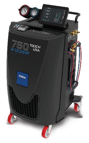

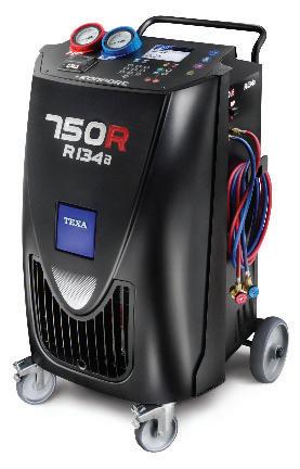





 BY BILL FULTON


