


Factories and plants look to machine builders for more energy-ef cient equipment


SEAMLESS eCAD TRANSDUCER TRANSLATION VENDOR INTEROPERABILITY APRIL 2024


Made in America Save 10-40% Over C-more CM5 & EA9, w/ 5-20% Bigger Display Same day Ship if Ordered by 6 p.m. CST Say No to CHINA & Invest in American Jobs EZAutomation.net Introducing Latest in EZTouch HMIs EZ5 Series HMIs 4" - $299 7" - $399 8" - $599 10" - $699 12" - $899 15" - $1299 Programming so simple that even your CEO can do it in minutes! Let's Compare HEAD-TO-HEAD to C-more CM5 & EA9 Save 10-30% over CM5 Starting at $299 Features EZAutomation EZ5 - $299 AutomationDirect CM5 AutomationDirect EA9 Price 4" - $299, 7" - $399 8" - $599, 10" - $699 12" - $899, 15" - $1299 4" - $340, 7" - $479 8" - N/A, 10" - $769 12" - $1029, 15" - $1609 4" - N/A, 7" - $794 8" - $1383, 10" - $1778 12" - $1545, 15" - $2803 Display Screen Size All EZ5 are standard screen sizes & not wide screen displays. 10"19.5%, 12" - 6.3%, 15"-4.9% bigger All wide angle displays, 5 to 20% smaller than standard size displays Standard size displays HMI On-line edit to change program without shutting down the HMI or the machine. Patented Online Edit Feature Not Available Feature Not Available LED back lighting 400 NITS, 75K Hrs @ 55°C 310 NITS, 50K Hrs @ 25°C310 NITS, 50K Hrs @ 25°C Touchscreen Rugged 0.090" thick anti-glare touchscreen Paper Thin Touchscreen Paper Thin Touchscreen Logic expressions to save PLC code Scripting / Expressions No Scripting / Expressions No Scripting / Expressions Program/Edit HMI screens from 50 ft away without a programming cable EZ-WiFi Programming Not Available Not Available Remotely monitor the Panel Yes, with real-time data loggingNo real-time data logging No real-time data logging 24 Hr. Burn-in Yes No No Made in America to create and sustain American jobs Made in America, Free of Tariffs Made in China, Constant threat of Tarrifs Made in China, Constant threat of Tarrifs FREE Legendary Programming Software Call 1-877-774-3279 for Application Assistance or visit www.EZAutomation.net/ez5 * All product names, and trademarks are the property of their respective manufacturers. EZAutomation disclaims any proprietary interest in the marks or names of others.

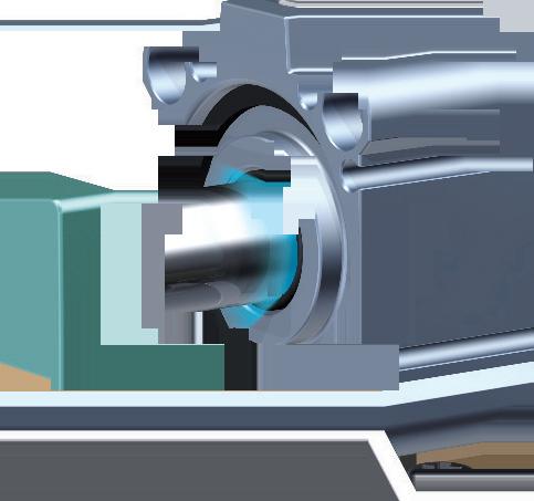
ACOPOS P3
Big impact, small footprint
With the ACOPOS P3, B&R is setting new standards for motion control. This 3-axis servo drive offers a power density of 4 amps per liter, making it one of the most efficient servo drives with integrated safety functions on the market. It also offers unrivaled dynamics and precision, with a sampling time of just 50 µs for the entire controller cascade.
•69% smaller footprint with highest power density
•No additional fans in the control cabinet
•The right solution for every machine
br-automation.com
B&R | A member of the ABB Group
Inside the cabinet? Outside? You choose with our powerful, ultra-compact IPCs

Small enclosures. Harsh environments. Evolving requirements. As engineers, we know these factors must be addressed constantly. Every new machine presents unique challenges and opportunities to innovate. So our ultra-compact Industrial PC series gives you freedom to choose the perfect controller for every machine. Maybe it’s the C6015 with dimensions of just 82 x 82 x 40 mm and outstanding installation flexibility. Or maybe your machine calls for the IP65/67-rated C7015 for cabinet-free installation. All IPCs in this series deliver powerful control to simultaneously run automation, HMI, edge computing/IoT and other communication – all on one controller. They make ideal gateways to the cloud and support flexible I/O system expansions – inside or outside of the cabinet. The choice is yours
Scan to discover all the IPC installation and application possibilities
| PC51USA


PLC system controls solar thermal power Control system optimizes energy harvesting, storage and distribution
cover story Standards and regulations fuel the green machine Factories and plants look to machine builders for more energy-efficient equipment Anna Townshend, managing editor 16 PLCs Open architectures impact PLC longevity How universal automation extends IEC 61131-3 Tobey Strauch, independent controls engineer 27 sensors How to verify transducer readings Machines rely on accurate analog-todigital conversion of 4-20 mA signals Larry Stepniak, Flint Group 29 product roundup Network links, gateways and switches Industrial networking devices keep data moving and systems connected 31 table of contents Volume 28, No. 2 ControlDesign.com / April 2024 / 5 CONTROL DESIGN (USPS 17792, ISSN 1094-3366) is published 6x annually or bi-monthly by Endeavor Business Media, LLC. 201 N. Main Street, Fifth Floor, Fort Atkinson, WI 53538. Periodicals postage paid at Fort Atkinson, WI, and additional mailing offices. POSTMASTER: Send address changes to CONTROL DESIGN, PO Box 3257, Northbrook, IL 60065-3257. SUBSCRIPTIONS: Publisher reserves the right to reject non-qualified subscriptions. Subscription prices: U.S. ($120 per year); Canada/Mexico ($250 per year); All other countries ($250 per year). All subscriptions are payable in U.S. funds. Printed in the USA. Copyright 2024 Endeavor Business Media, LLC. All rights reserved. No part of this publication can be reproduced or transmitted in any form or by any means, electronic or mechanical, including photocopies, recordings, or any information storage or retrieval system without permission from the publisher. Endeavor Business Media, LLC does not assume and hereby disclaims any liability to any person or company for any loss or damage caused by errors or omissions in the material herein, regardless of whether such errors result from negligence, accident, or any other cause whatsoever. The views and opinions in the articles herein are not to be taken as official expressions of the publishers, unless so stated. The publishers do not warrant either expressly or by implication, the factual accuracy of the articles herein, nor do they so warrant any views or opinions by the authors of said articles.
23 CREDIT: DEREK CHAMBERLAIN, GENERATED WITH SHUTTERSTOCK AI
PLCs
Flemming Jørgensen, Jorgensen Thermal Solutions


9 editor’s page Vision system increases energy efficiency Mike Bacidore, editor in chief 10 embedded intelligence The evolution of HMI Jeremy Pollard, CET 11 technology trends Pneumatic devices bring the I/O Rick Rice, contributing editor 14 component considerations Supercharge your workflow with eCAD Shawn Cox, contributing editor 15 automation basics Top robotic applications for sensor data Charles Palmer, contributing editor 34 real answers Do vendor-agnostic devices make sense? Anna Townshend, managing editor 42 live wire What’s old and new with machine safety? Joey Stubbs, contributing editor
Altech 6 B&R Industrial Automation .............................................3 Beckhoff Automation 4 Contemporary Control Systems 33 DigiKey 44 EZAutomation 2 Hammond ............................................................................ 28 icotek North America 41 Novotechnik 13 SMC 8
index ControlDesign.com / April 2024 / 7 table of contents Volume 28, No. 2 Endeavor Business Media, LLC 30 Burton Hills Blvd, Ste. 185, Nashville, TN 37215 800-547-7377 CEO Chris Ferrell President June Griffin COO Patrick Rains CRO Paul Andrews Chief Digital Officer Jacquie Niemiec Chief Administrative and Legal Officer Tracy Kane EVP Industrial Group Mike Christian VP / Group Publisher Keith Larson editorial team editor in chief Mike Bacidore mbacidore@endeavorb2b.com managing editor Anna Townshend atownshend@endeavorb2b.com digital editor Madison Ratcliff mratcliff@endeavorb2b.com contributing editor Rick Rice rcrice.us@gmail.com contributing editor Joey Stubbs contributing editor Shawn Cox brianshawncox@gmail.com contributing editor Charles Palmer charles101143@gmail.com columnist Jeremy Pollard jpollard@tsuonline.com design/production production manager Anetta Gauthier agauthier@endeavorb2b.com ad services manager Rita Fitzgerald rfitzgerald@endeavorb2b.com art director Derek Chamberlain subscriptions Local: 847-559-7598 • Toll free: 877-382-9187 email: ControlDesign@omeda.com circulation requests / classifieds Lori Goldberg lgoldberg@endeavorb2b.com sales team Account Manager Greg Zamin gzamin@endeavorb2b.com 704/256-5433 Fax: 704/256-5434 Account Manager Jeff Mylin jmylin@endeavorb2b.com 847/516-5879 Fax: 630/625-1124 Account Manager Kurt Belisle kbelisle@endeavorb2b.com 815/549-1034
COLUMNS
ad


 Mike Bacidore editor in chief mbacidore@endeavorb2b.com
Vision system increases energy efficiency
CONVENTIONAL SILICON ARCHITECTURE has taken computer vision a long way, but Purdue University researchers are developing an alternative path, taking a cue from nature, that they say is the foundation of an artificial retina. Like our own visual system, the device is geared to sense change and designed to be more efficient.
“Our long-term goal is to use biomimicry to tackle the challenge of dynamic imaging with less data processing,” says Jianguo Mei, the Richard and Judith Wien Professor of Chemistry in Purdue’s College of Science. “By mimicking our retina in terms of light perception, our system can be potentially much less data-intensive.”
Mei and his team drew their inspiration from light perception in retinal cells. As in nature, light triggers an electrochemical reaction in the prototype device they have built. The reaction strengthens steadily and incrementally with repeated exposure to light and dissipates slowly when light is withdrawn, creating what is effectively a memory of the light information the device received. That memory could potentially be used to reduce the amount of data that must be processed to understand a moving scene.
will let the machine make the decision faster with less data and fewer data requirements also means there will be a decrease in power requirements, making that machine more energy-efficient, explains Tutt. “I am interested to see where this evolution of computerized vision systems will go,” he says. “As this technology is modeled and a digital twin of the eye is created to generate a computer vision system, I think it could be implemented within the next five to 10 years.”
In industrial systems or machinery, there is typically a sensor with a computer behind it.
The team calls the device an organic electrochemical photonic synapse and says it more closely mimics how the human visual system works and has greater potential as the foundation of a device for human-machine interfaces (HMIs).
“I can definitely foresee this technology becoming a part of vision systems,” says Dale Tutt, vice president, industry strategy, at Siemens Digital Industries Software. “In the studies they are doing at Purdue University, researchers are able to mimic the results of the human eye in a way that requires less data requirements. That is intriguing to me.”
When you think about the various applications that have vision systems, the promise of collecting information that
In industrial systems or machinery, there is typically a sensor with a computer behind it, and the computer is doing the calculations and work, explains Tutt. “It appears that sensor could easily be replaced with more efficient optical sensors, which would lead to different algorithms that require less computing power to do the calculations and analysis of what the vision sensor is capturing,” he says. “In theory, many of the sensors could be replaced with this newer or evolutionary technology. I might even go so far as to say it has the potential be revolutionary technology, especially if we can combine it with artificial intelligence (AI) to truly mimic not only the vision powers of a human, but also the ability to problemsolve and make decisions the way a human does.”
Mei’s vision system, like human vision, is relatively lowresolution but is well-suited to sensing movement. Human eyes have a resolution in the neighborhood of 15 microns. The prototype device, which houses 18,000 transistors on a 10-centimeter square chip, has a resolution of a few hundred microns, and Mei says the technology could be improved by lowering resolution to about 10 microns.
“When we look at industrial vision applications, the first implementation that comes to mind is robotics in a factory or other similar situations that currently leverage computer vision systems,” says Tutt.

ControlDesign.com / April 2024 / 9
editor’s page
Jeremy Pollard jpollard@tsuonline.com
The evolution of HMI
A HUMAN-MACHINE INTERFACE (HMI) can come in various forms and had its genesis in hardware and firmware. I remember Steve Rubin, founder of Intellution, which is now iFix, telling the story of burning programmable read-only memory (PROM) on his kitchen table as a system update. The core of an early HMI has always been software/firmware that interfaces with specific hardware in the same space.
The video cards were normal, and there was a DOS interface to the video memory to draw the primitives—lights, buttons—and then a communication driver poached data from the system controller, typically a programmable logic controller (PLC) to animate these primitives.

tools and add-ons such as OPC UA for communication, so the screen and back-end processes can access multiple devices on the same platform, which typically would use Ethernet for connectivity. Again, software plug-ins would be used to integrate data from certain supplier devices into one HMI application.
A methodology that is thrown around a lot is edge computing, and the HMI is at the edge. What does this really mean?
A typical HMI hardware platform is an industrial, or commercial, PC mounted in or on the control panel.
Enter 1990 and Windows 3.0. A small company called Wonderware was working with Microsoft and developed Network DDE so they were intimate with the operating system (OS). The PC had been out for eight years using DOS as its OS, and HMI software was being developed under DOS, which Intellution migrated to and was the de facto leader in the space until.
Under Windows, Wonderware created a whole new ball game. Using standard interfaces such as video drivers and serial card/utility card drivers, a new HMI era was born. And we have never looked back.
The HMI provides the same level of interface as always—pump on/off and alarming, for example. But it has so much more capability in this age of networking, wireless and edge computing.
HMI is typically located at the machine level and is strictly software-based using standard PC-based hardware and systems. Some can support different programming languages, and most support template-based configuration of screens that the operator interfaces with.
A typical HMI hardware platform is an industrial, or commercial, PC mounted in or on the control panel, but, of course, the visualization can be a mobile device such as a smart phone or tablet. Connecting wirelessly is an option here.
In recent years, HMI software has become mainstream in the fact that it can and does use commercially available
An edge device is at the end of a network and has computing capabilities. In a previous life, the HMI would read data from the PLC, which would have been formatted by the PLC and displayed. This data would be recorded on a clipboard and sneaker-netted into an office for data entry.
Now, no clipboard should be implemented. The HMI can take the raw data from the PLC, format and put the data through algorithms created by scripting to produce a result that means something to someone or something like a database.
It’s where the database is located that is the game-changer. It can be located locally, but more often it is located in a server room in the plant. In recent years, data was mirrored from the server to the cloud, which is offsite to be made available for remote users.
Now, an HMI with Internet connectivity can use protocols reserved for server-based applications directly to send data to the cloud and to the third-party applications that use this data for a variety of decision-making instances.
HMI software is no longer a simple machine interface to an operator. It can interface to local back-end programs, such as a computerized maintenance management system (CMMS) or enterprise resource planning (ERP) system, and cloud-based third party applications directly and can provide remote access for monitoring and control, if needed.
JEREMY POLLARD, CET, has been writing about technology and software issues for many years. Pollard has been involved in control system programming and training for more than 25 years.
10 / April 2024 / ControlDesign.com
embedded intelligence
 Rick Rice contributing editor rcrice.us@gmail.com
Pneumatic devices bring the I/O
ONE OF MY PRIMARY responsibilities is identifying older equipment that is at risk of failure due to obsolete hardware in the control system and building new controls to replace them. Much of my target equipment started life in the 1980s. It is a tribute to the designers of this equipment that it has survived 40 or more years of daily use and still performs the job it was designed to do.
What is interesting is the comparison of what were industry-leading techniques and technology back in 1980 compared to where we are. A recent controls upgrade project provided a reminder of the importance of choosing the right components for pneumatic operations.
an actuator. In each position, the spool, or valve station, directs flow from the pressure port while the other actuator port exhausts to atmosphere. For a three-position valve, two solenoids are required to shift the spool. In the de-energized state, springs on each end of the valve spool keep the valve in the center position. This is normally all ports blocked and exhaust. To operate an actuator, the desired direction must remain powered on. Removing power returns the valve to the center/blocked position.
Pneumatic vendors thought to combine the remote I/O with the manifold directly.
Any deep dive into the journey that technology has taken over the past 40 years should start with the statement that, at its base, the principles of operation remain the same.
Pneumatic valves come in three primary types—two-way, three-way and four-way.
Two-way two-position valves can be normally open or normally closed. They are direct acting valves where a single solenoid initiates a shift in the valve to the opposite state, and a spring returns the valve to the normal position after power is removed from the solenoid.
These valves pressure and exhaust one outlet port. The outlet either has pressure or it is blocked, depending on the position of the valve. A good example of use would be a blast of air to blow a product off a conveyor.
Three-way two-position valves can be normally open or normally closed. They are direct acting valves where a single solenoid initiates a shift in the valve to the opposite state, and a spring returns the valve to the normal position after power is removed from the solenoid. These valves pressure and exhaust one outlet port. The outlet either has pressure or it is clear to exhaust, depending on the position of the valve. A good example of use would be an actuator that would energize to extend and de-energize to retract to the original position.
Four-way two-position valves typically have four or five ports and two or three positions. For each position, there are two distinct flow paths for extending and retracting
These basic principles of pneumatic and hydraulic valves have not changed. Another key principle or rule of thumb is to keep the length of hose from valve to actuator as short as possible. This keeps the action as responsive and quick as possible.
Air is compressible, so the longer the length of hose, the more air must be applied to cause an action at the actuator. For dual port valves, keeping the hoses the same length is important to keep the extend and retract actions the same.
Flow controls have a considerable impact on the actions of pneumatic devices. When used on an actuator, the flow control limits the release of air on the opposite side of the actuator and is used to control the speed of the action.
Further, end cushions in cylinders create, as the name suggests, a cushion of air right near the end stroke of the actuator. This allows for a speedy main movement, depending on the flow control setting, and then a final deceleration, as it were, of the actuator when it meets up with the cushioned part at the end of stroke. These two functions can be compared to controlling the speed and deceleration of a variable-frequency drive to control the motion of a motor-driven device.
None of the preceding details changed much over the years. Individual manufacturers continue to tweak an already good and long-standing product to further improve the function. For example, the inner chambers and paths in both valves and actuators are worked on to improve the flow of air to optimize performance.
One manufacture I work with has come up with a new valve body that uses the same physical size but a signifi-
ControlDesign.com / April 2024 / 11
technology trends
technology trends
cantly improved volume of airflow. This increases speed of shifting and, by association, greater speed of the actuator.
For a designer, understanding how pneumatic devices behave is a very important part of coming up with a good controls package. For example, due to the use of flow controls and end cushions, some movements that are physically longer would benefit from sensors to indicate the position of the actuator.
We cannot rely on time because that can vary, depending on the settings for flow or end cushion. In critical movements where paths might cross with other actuators, assuming that an actuator is out of the way, based on time, will likely result in a collision.
The biggest development in pneumatic control likely came out of the understanding that the distance from a valve to an actuator is critical. In larger machines or process applications, the distance from the control cabinet to the field device might be quite long. The solution to that was to mount the manifold or a smaller version of it on the machine, close to the devices.
Traditionally, machine wiring would carry signals to that machine-mounted manifold, which added some latency to the actions due to inherent lag associated with sending signals over long distances, but it kept the actuator connections as close to the valve manifold as possible. Thankfully, the fieldbus entered the picture. A fieldbus does just that, moves the originator of the signals from the main control panel to the field-mounted device using communications.
Communications, even in the earlier days of this technology, was much faster than the physical wires strung on the machine. Instead of a multiconductor cable strung along the frame of the machine, the communications cable consisted of a few conductors, as few as two or five plus a shield, in its own protected jacket.
The first versions of this technology involved mounting field, or remote, I/O stations at strategic locations on the machine or process and then controlling the pneumatic devices from that close proximity. Power plus communications cables were the only wires needed to get from the main cabinet to the remote station.
The real innovation came from these original concepts. Pneumatic vendors thought to combine the remote I/O with the manifold directly, in one bundle that could be mounted right there on the side of the machine.
Contained in the manifold block is a communications module talking in whatever version of fieldbus the designer chooses to use. The control of the manifold is direct terminations that happen from the communications module to the backplane of the manifold—neat, clean and protected.
We now have the ultimate version of this concept. If you have pneumatic devices, you likely also have inputs and outputs in the immediate vicinity. Instead of mounting a separate remote I/O station, why not have modules that connect directly to the valve manifold and use that same backplane connection to talk to the embedded communication module?
The number of additional I/O modules is only restricted by the fieldbus protocol and the capabilities of the communications module.
The use of fieldbus technology is changing the way we design and build machines and processes. It drastically cuts down on wiring and puts specialty function modules on a machine where they once were restricted to the main processor rack in a control cabinet.
Where we once had to put such equipment in a protective enclosure on a machine, many of the fieldbus on-machine devices can live right there in the harsh environment, again reducing design and build costs. Since these devices are usually field-configurable, the ability to add or subtract manifold stations and input/output stations at a time after design makes them all the more attractive.
Adapting to change can be hard. As humans, we seem bound to resist such changes, and that can hold us back at times. Challenges can exist, for example, when upgrading a system that didn’t have a proper safety circuit in it. By adding that safety circuit and the necessary means to cut off power to field devices, we created an issue where a dust control valve that needed to stay open for cleaning was closing when we hit the e-stop.
Using technology and knowledge, we were able to change the control at the device to use a double-ended valve that would stay in the last position if we pressed an e-stop to drop power. Using the new technology in our upgrade saved the day for us because we already had additional control points in the manifold and simply changed out the valve.
RICK RICE is a controls engineer at Crest Foods (www.crestfoods.com), a dry-foods manufacturing and packaging company in Ashton, Illinois.
12 / April 2024 / ControlDesign.com

component considerations
Shawn Cox contributing editor brianshawncox@gmail.com

Supercharge your workflow with eCAD
ELECTRONIC COMPUTER-AIDED DESIGN (ECAD) represents a suite of specialized digital tools meticulously crafted to cater to the intricate demands of electrical design. With its robust features and tailored functionalities, eCAD software empowers engineers and designers to seamlessly craft intricate schematics, to meticulously plan panel layouts and to map out wiring diagrams with unparalleled precision.
One of the key strengths of eCAD lies in its ability to enhance efficiency across the design workflow. By automating repetitive tasks and providing intuitive design aids, it accelerates the pace of development, allowing teams to meet deadlines with confidence. Moreover, eCAD software minimizes the risk of errors inherent in manual design processes, thereby bolstering the reliability and integrity of the final product.
workflows, enabling technicians to access critical components for inspection or repair.
Cable and wire harness design represents another aspect of electrical system engineering, involving the systematic arrangement and interconnection of cables and wires. Through planning and organization, cable and wire harness designs optimize signal transmission, minimize electromagnetic interference and bolster overall system reliability.
The software fosters seamless collaboration among design teams.
The software fosters seamless collaboration among design teams, irrespective of geographical boundaries. Through features like real-time collaboration and version control, it ensures that all stakeholders are on the same page, promoting synergy and cohesion throughout the design lifecycle.
Electrical schematics serve as indispensable visual guides, detailing the intricate arrangement and interconnection of electrical components within a system. These schematics are akin to blueprints, providing a clear roadmap for technicians and engineers to follow during installation, troubleshooting and maintenance tasks.
By illustrating the precise wiring connections and component configurations, electrical schematics facilitate the swift identification and resolution of potential issues, thereby enhancing operational efficiency and minimizing downtime.
Panel layouts, on the other hand, are vital blueprints that present the strategic positioning of electrical components within control panels or cabinets. These layouts are crafted with attention to detail, ensuring not only efficient organization, but also proper spacing and accessibility for maintenance and troubleshooting.
By adhering to standardized design principles and ergonomic considerations, panel layouts streamline operational
By adhering to best practices in cable management and routing, such as implementing shielding techniques and employing appropriate cable dressings, engineers can mitigate the risk of signal degradation or cross-talk, thereby ensuring the functionality of the electrical system. Enhance design accuracy and efficiency by utilizing advanced tools and methodologies. Streamline processes, reduce errors and achieve superior results through precise planning, effective collaboration and continuous improvement in design practices. Facilitate seamless collaboration among design teams with integrated communication tools and shared platforms.
By providing a comprehensive suite of digital tools tailored specifically to the needs of control design, eCAD accelerates the prototyping process, allowing engineers to iterate and refine their designs with ease. Through advanced simulation capabilities and virtual testing environments, eCAD software enables designers to anticipate potential issues and optimize performance before a single component is fabricated, significantly reducing time to market and enhancing product quality.
Moreover, eCAD simplifies troubleshooting by providing engineers with detailed insights into the functionality of their designs, facilitating rapid diagnosis and resolution of issues. Whether it’s identifying faulty components or optimizing wiring configurations, eCAD empowers engineers.
SHAWN COX is a licensed master electrician/PLC programmer. He was co-owner/operator of Bobby Cox Electric for 15 years and is currently employed by BMW Manufacturing as an ESA.
14 / April 2024 / ControlDesign.com
 Charles Palmer contributing editor
Top robotic applications for sensor data
AS WE MOVE INTO a digitalized world filled with new technologies, the movement toward smart sensors—those that can and do talk to the Internet, the cloud and the edge—is gaining popularity almost exponentially.
Remember that applications for these also include “dumb” or analog devices.
Position sensors play a crucial role in robotics by providing information about the location, orientation and movement of robotic components.
These sensors are used to enable robots to navigate, manipulate objects and interact with their environments. Here are several ways that position sensors are used in robotic applications:
Feedback from the sensors is used to continuously adjust and control the robot’s movements, ensuring accuracy and stability. Closed-loop systems correct errors and deviations from the desired position.
Robotics application 5 — collision detection
For this we use force or torque sensors. Force/torque sensors on robot arms can detect unexpected contact with objects or obstacles. This information is crucial for implementing safety measures, preventing damage to the robot or its surroundings and enabling collaborative-robot (cobot) applications.
Wheel encoders and IMUs help estimate the robot’s position and orientation as it moves.
Robotics application 1 — Joint position sensing
For these applications, rotary or linear encoders, potentiometers, resolvers are used. Robots have joints that move in various ways, such as rotational or linear motion. Position sensors attached to these joints provide feedback on the angles or positions of the joints. This information is essential for precise control of the robot’s movements.
Robotics application 2 — end-effector positioning
Here we use force/torque sensors, six-degrees-of-freedom (6DOF) sensors, vision systems. In terms of how these are applied, position sensors on the end effector—the tool or hand of the robot—help to determine its position and orientation in three-dimensional space. This is critical for tasks like pick-and-place operations, assembly and other applications requiring precise manipulation.
Robotics application 3 — absolute and relative positioning
In this application, absolute encoders or relative encoders are employed. Absolute encoders provide the precise position of a robotic component, while relative encoders measure changes in position. Both types are used in robotics for tasks ranging from navigating within a workspace to controlling specific joint movements.
Robotics application 4 — closed-loop control systems
A closed-loop control system uses feedback from a measurement device, a sensor. Position sensors are integral to closed-loop control systems.
Robotics application 6 — navigation
For navigation and odometry, wheel encoders or inertial measurement units (IMUs) are generally used. For mobile robots or autonomous vehicles, wheel encoders and IMUs help estimate the robot’s position and orientation as it moves through space. This information is essential for navigation and mapping tasks.
Robotics application 7 — sensor feedback signals for control algorithms
These can be various types of encoders or sensors. To move under control, the robot has position sensors which provide feedback to control algorithms, allowing robots to adapt their movements based on external stimuli or changes in the environment. This adaptive capability is crucial for tasks like obstacle avoidance and responding to dynamic environments.
Robotics application 8 — orientation
Orientation control or dynamic balancing is achieved through the installation of inertial measurement units. These devices are used in balancing robots and humanoid robots to maintain stability by constantly measuring and adjusting the robot’s orientation. This is particularly important for applications such as walking, climbing stairs or traversing uneven terrain.
Charles Palmer is a process control specialist and lecturer at Charles Palmer Consulting (CPC). Contact him at charles101143@gmail.com.
ControlDesign.com / April 2024 / 15
automation basics


 BY ANNA TOWNSHEND, MANAGING EDITOR


16 / April 2024 / ControlDesign.com cover story
MANY DIFFERENT
ENVIRONMENTAL regulations are affecting manufacturing, namely driven by U.S. commitment to the 2015 Paris Agreement or Paris Climate Accords, which pledges to achieving net zero greenhouse gas (GHS) emissions by 2050. This will be an immense challenge for industry, driving sustainable options to become more standard in machinery. But first, to improve sustainability, manufacturers must measure energy usage and standardize energy management data.
Many machines depend on pneumatic power as much as they do on electric power, and compressed-air conservation will also play a large role in making machines more sustainable.
Manufacturing operations are already supporting these efforts in many ways with communication protocols for energy metering, strong supervisory control and data acquisition (SCADA) foundations and fieldbus connectivity that brings data to the device level.
One truth to measurement
To improve sustainability, it’s imperative to first measure the machine’s energy usage. Tracking usage opens the door to being able to identify areas of waste and opportunities to reduce usage of limited resources, such as through turning off unneeded equipment automatically, says Steve Fales, director of marketing for ODVA. There is a significant opportunity to make achieving sustainability not only possible, but profitable, he says.
To support these efforts, ODVA is participating in a joint consortium to standardize power consumption management and develop a new OPC UA interface standard to acquire energy
consumption data in industrial manufacturing. The joint effort is being co-developed by ODVA, the OPC Foundation, PI North America and VDMA. The initiative is designed to optimize energy usage and thereby reduce the detrimental impact on the environment from waste, explains Fales.
“The Power Consumption Management collaboration will help ensure end users have a highly standardized and interoperable means to reach their environmental, social and corporate governance (ESG) goals,” Fales says. Work began in 2022, and the group is actively working to develop the specification.
of energy information or dynamic demand-response,” says Fales.
“CIP Energy allows systems to monitor energy usage and manage energy for efficient energy consumption through dynamic control of energy state and analysis of energy information,” Fales says. Repeatability, consistency and simplicity are the key factors to making this protocol scalable, he adds. CIP Energy identifies the key energy usage attributes that are consistent across EtherNet/IP devices, and the information is stored in energy objects for easy access, management and reporting.
“The idea is to be able to use devices fully when they are needed as a part of the process and to be able to reduce power usage when they are not. Additionally, understanding power usage across a process can allow for identification of areas where waste can be reduced,” Fales says.
Standardization of energy usage data will enable greater adoption across automation industries. “Having data labelled in the same way and measured in the same scale will allow for greater benchmarking and comparison across industries as well,” he adds.
ODVA is also working to contribute to sustainability efforts in industrial automation through CIP Energy, a network extension for EtherNet/IP. “CIP Energy provides a family of objects and services for the optimization of energy usage (OEU) and allows scalability of implementation within the device from basic energy awareness to more advanced functions for control of energy, aggregation and reporting
“Protocol-neutral energy attributes allow for flexibility in the propagation of energy information via multiple protocols to facilitate an e-business model, such as capturing energy requirements as a line item on production bills of material or to implement demand-response mechanisms for dynamic energy transactions,” he adds.
This is supported by the work done by the Power Management Consumption consortium and the developing OPC UA interface standard. “Business reporting will be much easier knowing that energy data from multiple communication protocols will be formatted in a consistent way with the same labelling and scaling. CIP Energy is one of the existing standards that will contribute to the new OPC UA interface standard,” Fales adds.
ControlDesign.com / April 2024 / 17 cover story
7 TRENDS CRAFTING MORE EFFICIENT MACHINES
More sustainable machines and the processes they drive will be a key part of many industrial strategies, and they are already influencing machine design and operation. In many cases, these same practices are already used in the name of efficiency, cost savings and profitability.
1
Sustainability will soon be an equal player in that arena, leaning into the efficiencies industry has already capitalized on and bringing in new opportunities.
More flexible and open machine design will support the data infrastructure and accumulation needed for more
LITHIUM BATTERIES FOR MOBILE POWER
When a pet-food manufacturer wanted a more efficient method for sampling products in various parts of the plant, it went to Gray Solutions, a system integrator, based in Lexington, Kentucky. The legacy solution was a pneumatic carrier tube system, but Gray Solutions recommended an autonomous mobile robot to move materials to and from production lines with operators. “This solution was much cheaper overall but also had a significant impact on energy usage,” says Greg Powers, vice president of cool stuff at Gray Solutions.
AMRs and automated guided vehicles (AGVs) use lithium batteries, which are more efficient than motors to run conveyor belts. “Rechargeable batteries are much more efficient than long conveyors with many motors,” he adds. The AMR solution was also cheaper overall than replacing the old system of pneumatic tubing and vacuum motors.
Overall, Gray Solutions has many customers asking about energy usage monitoring for their automation projects, including the sensors and devices used to capture the needed data. “In addition, since we are heavily involved in building manufacturing facilities, reduction in emissions and greenhouse gases is always a consideration in adopting these technologies or processes for greenfields,” Powers says.
2
WIDE-BANDGAP MATERIALS IN SEMICONDUCTORS
Silicon has been dominant in semiconductors for many years but is reaching its performance limits. New materials for semiconductors have the potential to make significant impacts on energy consumption. Wide-bandgap (WBG) semiconductor materials can make electric components smaller, faster and more efficient than silicon-based counterparts.
“New technologies, such as wide-bandgap technologies— silicon carbide (SiC) and gallium nitride (GaN)—apply to power conversion and inversion, and motor drives and control,” says Alex Wood, global senior marketing director at Avnet Embedded. “Power conversion and inversion involves high-voltage switching. DC and ac motors require conversion and inversion. The speed of switching and how easily these devices can be controlled directly impacts overall efficiency and losses.” WBG materials switch faster and with fewer losses than incumbent
efficiency gains. Likewise, technology advances in batteries, semiconductor materials, electric control, pneumatic actuation and design advances for more flexible and open communication and data sharing will provide the next level of efficiency standards.
solutions, such as insulated-gate bipolar transistors (IGBTs) and metal-oxide-semiconductor field-effect transistors (MOSFETs), explains Wood. “Although WBG devices are currently more expensive than their IGBT and MOSFET counterparts, the price difference is moving in the right direction, while the gains in terms of energy efficiency are already here,” he says.
In industrial machine design, Wood says that moving motor drives toward the use of WBG is probably slower than in new markets, such as electric vehicles (EVs) and EV charging, where WBGs are used for power conversion and inversion. However, he also says that the leading semiconductor vendors in this area have a very clear objective to enable the industrial market to benefit from the gains offered by WBG.
3
TIGHT, PRECISE CONTROL
Jim Larsen, focus industry manager of food and beverage at Burkert USA says both large and small companies are increasingly investing in monitoring and traceability technology for resources like energy, water and compressed air.
“Further, companies are taking a serious look at equipment that can deliver precise control,” he says. “The motivation here is there is efficiency and resource savings in precision. Devices that control to a tighter tolerance utilize fewer utilities. Additionally, devices that simply take less energy to operate are obvious targets.”
More compact systems and components are also a part of sustainability. Block-style manifolds and complex piping flow paths allow for more accurate and efficient control of applications like process heating and cooling, clean-in-place (CIP) cycles and faster switching between media, Larsen says. “There is a blended approach to using electric control and pneumatic actuation in the same process control loop, based on which is more effective to provide the desired results,” he explains. “Precise control of critical process systems is a means to optimize system efficiency. For example, when looking to control a heating or cooling process, the faster that system can be stabilized and the more tightly it can be maintained, the more efficient it is overall. When precision capability is combined with lower energy consumption by the devices themselves, there is a direct and very desirable impact to not only sustainability initiatives, but return on investment/total cost of ownership as well.”
18 / April 2024 / ControlDesign.com cover story
With dynamic demand response, a machine device could go into low power when not needed. On a larger scale, demand response can balance energy generation, distribution and usage through planning, analytics and utilities/end-user cooperation. “Power generation and distribution utilities are looking to predict a stable amount of energy usage over time to be able to deliver power when and where it is needed efficiently. End users are trying to minimize energy usage to the extent possible, while also working with utilities to use a consistent amount of power at given times per contractual agreements and pricing incentives. The combination of pricing incentives and agreements also works to reduce grid usage at peak operating times. Additionally, utilities work to make sure that they are delivering power optimally by delivering intermittent power loads when and where they are needed the most to ensure that the grid is stable and end users don’t see disruptions in critical processes. End users having devices that can optimize power either based on usage or time can aid in cooperating with utilities on energy usage,” Fales says.
Under pressure
Pneumatic systems are among the biggest energy wasters, and the inherent inefficiency of compressed air also makes it expensive.
“Monitoring is key to all sustainability efforts,” says Jon Jensen, energy efficiency team manager at SMC. “At the machine level, we see trends toward monitoring the pressure, flow, temperature and dewpoint of compressed air, allowing for data-driven decisions. There is also a growing importance for sensors that use little power, are
easy to install and can even communicate wirelessly. Machine builders and system integrators are asking us to produce components that use less energy to operate, both electrically and in their compressed-air consumption. There is specific interest in innovative technologies that use less compressed air than traditional components. Additionally, these customers are asking for more advanced monitoring systems to identify opportunities for even more energy savings.”
Jensen says increasing sustainability standards are driving industrial machine design to be more automated or semi-autonomous. “Automated machinery will soon be expected to have the monitoring necessary to reduce air consumption whenever and wherever by controlling pressure and flow,” Jensen says. “Machines will also be expected to have capabilities for self-diagnosis. For example, continuous monitoring of flow can be used to predict the failure of pneumatic components; an increase in flow can be attributed to a leak, which is a sign of wear. Mapping the flow profile against the motion profile of a machine can isolate the location of a leaking component to a specific circuit.”
With the motion profile already in the machine’s sequence of operations, software can compare the flow profile—peaks and valleys—and correlate to actions in production. “For example, let us say that the flow 20 seconds into the machine’s cycle is normally 10 standard cubic feet per minute (SCFM). After some time goes by, the software notices that the flow at that timestamp is now 15 SCFM. If we also have the machine’s sequence of operations, it could be determined that Cylinder 3 is retracting at that point, which
narrows the problem down to just a few components in that part of the circuit—the cylinder rod seal, a fitting or flow control and the tubing between the directional control valve and the cylinder,” Jensen says.
Ultimately, a focus on sustainability will involve designing systems to enhance operator interaction and engagement with energy management. “Real-time monitoring will provide insights and data that empower individuals to make energy-efficient decisions; it will bridge the gap between emerging technologies, artificial intelligence, sensors and regulatory procedures, emphasizing the importance of human resources in future energy management,” Jensen says.
Strong SCADA
Mitsubishi Electric also sees strong end user interest in SCADA systems for better monitoring capabilities on the overall industrial process, individual machines and components. “SCADA also becomes the foundation for other data analysis by creating historical stores of data to be mined by layered artificial intelligence (AI) applications,” says Patrick Varley, product marketing manager at Mitsubishi Electric.
While many are embracing sustainability, some still have investment cost and profitability concerns.
Part of a well-designed system means selecting the most suitable equipment, without over-specifying. “Often, there is a tendency to select more powerful motors, robots and controllers than needed. This means that companies may be overpaying and underutilizing their equipment, leading to energy inefficiencies and unnecessary costs,” Varley adds.
ControlDesign.com / April 2024 / 19 cover story
ELECTRIC VS. PNEUMATIC
“More critical thought is given to engineering choices, starting with the decision whether to go primarily with electric or pneumatic automation for the machine,” says Frank Langro, director of product market management, pneumatic automation at Festo. “This decision comes down to the application as well as cost. When the choice is to use pneumatics, OEMs are more interested today in optimum sizing than they have in the past, as proper sizing not only saves energy, it also saves on cost of components and contributes to overall equipment effectiveness.” OEMs use Festo pneumatic sizing tools much more frequently, says Langro. “This is in contrast to engineers selecting a valve based on the cylinder’s port size. Now it is sizing for optimum performance,” he explains.
The automotive industry has been trying to move away from pneumatics and go all-electric with their production lines for years, Langro says. “It was a result of energy costs, the cost of generating pneumatic compressed air was seen as more expensive than running electric for electric servo drives and steppers,” he adds. However, certain applications demand the forces needed from pneumatics, or space constraints demand compressed air.
The packaging industry, Langro says, is also embracing electric where possible, with many machine builders producing all-electric versions of, for example, a case packer or box erector. There also may be instances where machines require electric and pneumatic power, because of space or cost concerns. “We see both approaches being used in the market,” Langro says.
Typically, the component cost for a new electric system will be more expensive than pneumatic. “Pneumatic is a low-cost technology. But there is an overhead that goes with pneumatics in terms of having a compressed air system in your facility,” Langro says. Likewise, in a brand-new facility with no installed infrastructure, the pneumatic system would cost more from the ground up. “If you’re going into an existing facility that already has a pneumatic system and infrastructure in place, there’s minimal add-on cost,” Langro says.
5
SOFT STARTERS AND VFDS
“OEMs are increasingly more conscious of energy consumption than ever before,” says Jason Demicoli, product line manager, switches, Americas, at Carlo Gavazzi. “We started getting more requests for products that do not just switch the loads on/off but also help in reducing energy consumption.” Variable-frequency drives (VFDs) are one solution, when used properly, that can reduce energy costs in motor-control applications.
“In applications where the motors run at full speed, the soft starter is more efficient than a VFD as it has lower losses during operation,” Demicoli adds.
6
CONTROL FLEXIBILITY
Flexible and reconfigurable machines support the scale-up of new operations and help facilities more easily upgrade legacy equipment to match market needs. “Controls technologies can support sustainability efforts in several ways,” says Patrick Varley, product marketing manager at Mitsubishi Electric. “First, as they have become more versatile and easier to use, they help make sure that equipment remains serviceable, optimizing uptime. In addition, it is easier to repurpose controllers and monitoring systems to suit different projects as companies progress forward in their digitalization and sustainability roadmaps.”
As with most manufacturing technologies, increasing the flexibility to accommodate future automation requirements is important, adds Varley. This enables users to add to I/O to control more machines or utilize different communications protocols, which may be required if a new device needs to be added to the machine, he stresses.
Machine designs that offer greater availability to monitoring capabilities, through integration with supervisory control and data acquisition (SCADA) systems, support the flexibility needed to meet sustainability and profitability and operation standards, Varley adds.
7
OPEN ARCHITECTURE AND SHARED DATA
Upgrading legacy systems with monitoring capabilities to support more efficient operations will be a big challenge for many older facilities, but they can start by establishing open network architecture that will help future integration. Clean data collection and modeling will also be a key foundation to optimizing for energy efficiency.
“Soft starters are also a technology that may result in energy savings by reducing peak demand from motor loads,” Demicoli says. In heat-pump applications, this can require less over-sizing of generators and off-grid inverters.
“Machine builders are also developing energy-ready machines for seamless integration into end users’ energy management systems,” says Corinne Pellish, sustainability partnership and program manager at Rockwell Automation. “These machines are engineered to connect with nearby equipment and operate in an energy-efficient manner. A crucial design approach involves establishing a network infrastructure using an open, unified network architecture. Additionally, to facilitate seamless integration, manufacturers are designing an object-based data model that enables shared data across the system, library management at the automation layer and automatic discovery by the information layer. In terms of energy-ready machines, OEMs can create the common data model around water, air, gas, electric and steam data.” 4
20 / April 2024 / ControlDesign.com cover story
Sizing a motor, for example, will depend greatly on the application and specific motor manufacturer’s specifications. “One significant area of energy reduction will be supported by the use of an inverter to drive the motor. Inverters offer the ability to drive a motor with just the energy needed for the application,” Varley says.
As they operate non-stop for years at a time to support production lines, the impact of reducing the energy consumption of drives, controls, robots and other factory automation devices, even by a fraction, can be significant, says Varley. “Extending their lifecycle can help cut waste of materials that cannot be recycled or repurposed. In both cases, companies can benefit from reduced total cost of ownership, which, in turn minimizes CAPEX and OPEX,” Varley adds. “By designing the production machines with enough flexibility to be able to be modified for the needs of future iterations of the end product, you can extend the life of the equipment used on the manufacturing floor.”
Fieldbus connectivity
More original equipment manufacturers (OEMs) are looking for monitoring capabilities with fieldbus connectivity, says Jason Demicoli, product line manager switches for the Americas at Carlo Gavazzi. “With Industry 4.0 mentality, it’s not just expected that field devices switch the load, but the need for more data down to the field devices is becoming almost a default,” he says. In more complex machines, such as plastic extruders, injection, thermoforming or semiconductor equipment, programmable logic controllers (PLCs) must manage sometimes hundreds of components, says Demicoli. “If we can interconnect all field devices back to
Fieldbus connectivity down to the component level is an important controls step for sustainability efforts and the need to measure, monitor and adjust.
the main brain, then the possibilities of increasing the machine capabilities are endless,” he adds.
Fieldbus connectivity down to the component level is an important controls step for sustainability efforts and the need to measure, monitor and adjust, explains Demicoli. “Supervisory controls/monitoring can give you a general understanding of the machine behavior, but, in the era of the Industrial Internet of Things (IIoT), more detailed data is required,” Demicoli says. “When analyzed properly, this detailed data can help machine builders have a better process control but also can help them improve future designs. Data collected from field applications can start becoming an asset to monetize since different models for machine learning can be created.”
It is also important to be compatible with the different industrial protocols, such as EtherNet/IP, EtherCAT, Profinet, Modbus TCP, IO-Link, he says.
Heating elements and more in plastic injection machines
Carlo Gavazzi’s NRG Smart Solid State Relay with built-in monitoring and fieldbus communication is used in plastic injection machines to measure energy consumption. “In sensitive heating processes, such as plastic injection machinery, the monitoring of heating elements is critical to ensure a consistent process that yields a highquality product and make sure that, if a heater breaks, countermeasures are taken instantly to avoid costly damages to screw feeders, as well as
the high scrap cost,” Demicoli says. “Additionally, variations in the heating element resistance, especially in an open-loop system may also result in high energy consumption.”
In order to maintain a precise temperature in the mold zones, the plastic injection machines can benefit from fast switching of the heating elements via the solid-state technology, says Demicoli. Electro-mechanical contactors and relays could also do this, but frequent switching leads to frequent field replacement, he adds.
“This is more a lifecycle cost issue. A solid-state relay’s lifetime is measured in millions of cycles, which means less scrap, lower lifecycle cost and less need to throw away faulty components when they reach their lifetime,” Demicoli says.
Blown film extrusion processes use infrared heaters strategically along the extrusion line, to maintain the required temperature for proper melting and processing of the plastic material. “Through a soft-start function, the inrush current of the heaters is eliminated thereby avoiding temperature shocks to the heaters but also avoiding possible temperature overshoots,” he adds.
Demicoli also says that monitoring energy consumption (kwH) between equivalent machines in a production facility can also identify areas for implementing energy-saving initiatives.
Voltage sags can also greatly affect open-loop processes and are typically related to the power network quality and/or a fault on the power network.
ControlDesign.com / April 2024 / 21 cover story
Voltage compensation features can automatically correct the output power to compensate for voltage sags. “In the case of a process involving openloop heater control, voltage compensation mimics the functionality of the PID loop with an instantaneous reaction,” Demicoli says.
Energy-management communication protocols
Sustainable practices for each manufacturer may also extend beyond its shop floor, up and down the supply chain, and more end users may soon be asking for data about the environmental impact of materials and processes.
“Standards are also coming into play as we evaluate the carbon footprint of our manufacturing supply chain and supply our customers with the data they need to evaluate us as part of their supply chain. We are already starting to publish data about the product environmental footprint (PEF) of our products such that customers can complete this evaluation,” says Lou Grice, vice president of digitalization and government relations at Phoenix Contact.
“In B2B environments, companies should consider that their downstream customers may require some statement of the environmental impact made by their suppliers,” Grice says. “In general, this means that data provided by suppliers about products and services should be expanded to include data linked to sustainability concerns like PEF. Depending upon the product, the PEF will account for various value chain items, including materials and manufacturing process used to make the product as well as product distribution, use and end-of-life,” he adds.
With at least one control cabinet and available space, monitoring meters can be installed on machines with minimal considerations.
As example, the PEF for a Phoenix Contact feed-through terminal block shows the material composition, environmental considerations for product manufacturing, customer distribution, use phase and end of life. Emissions data and calculations from general databases and emission reports from its suppliers were used to calculate the product environmental footprint.
Phoenix Contact also uses green energy, such as solar power, wind generation, energy storage and hydrogen gas, and its EMpro energy monitor supports sustainability efforts at its manufacturing facilities. “When we have a need to monitor multiple circuits with mixed voltage levels, we use a solution with our PLCnext controller and our Axioline power measurement modules,” says Russell Kolacek, building automation engineer at Phoenix Contact. “For data collection, we use common data manipulation protocols such as representational state transfer (REST) application programming interface (API) and message queuing telemetry transport (MQTT) to gather and share data. We store meter readings in a time-based database, which we can review and analyze later.”
He says REST API was used because the energy meter was supporting direct polling of live values. The meter’s implementation was also well-documented, which allowed the backend programming to be created.
“Using both REST API and MQTT as open communication protocols means
our internal application can have long lifecycle, as it is not dependent on a proprietary protocol or communication that is burdened by a license. We can maintain and adapt this code base as necessary. It is also lightweight and well supported by many IIoT frameworks,” Kolacek adds.
Time-based databases are efficient when working with energy data, Kolacek adds. “We are concerned here with the efficiency of storage both in the speed of read/write of the data and in the amount of storage it occupies,” he says.
Phoenix Contact is working with machine builders to design the power meter into the main cabinet of machines.
For a time, many machines will need to be retrofitted with energy monitoring solutions. With at least one control cabinet and available space, monitoring meters can be installed on machines with minimal considerations, Kolacek says. For installation, consider the power distribution layout for the machine and the available space needed for the energy meter.
“Installing in the field requires an additional electrical enclosure and planning for a machine power outage. We typically will locate the energy meter at the delivery point of power for the machine, so we must find space to locate this additional panel. Using a machine built with energy monitoring included, we simply have to bring data monitoring to the machine, making installation much simpler,” Kolacek says.
22 / April 2024 / ControlDesign.com cover story


PLC system controls solar thermal power
Control system optimizes energy harvesting, storage and distribution
by Flemming Jørgensen, Jorgensen Thermal Solutions
SOLAR THERMAL IS a highly effective method for large-scale energy production in geographies with high levels of direct sunlight. For industrial operations with signi cant heat consumption, solar thermal is often more cost-effective than fossil fuels, and it also results in lower carbon-dioxide emissions. Solar thermal is especially attractive in situations where land is plentiful and readily available.
At a remote mining facility in northern Mexico, heat accounts for an important amount of energy consumption at the plant. This is due in part to the heavy use of electrowinning, also known as electroextraction, a process used to obtain metals from ore. Electrowinning can require a tremendous amount of heat energy, and most copper mines using the electrowinning process rely on boilers to support this
process. Because of the abundant access to land and nearly 3,000 sunshine hours available per year, solar thermal was an obvious choice for this site.
Jorgensen, a large-scale solar heating equipment and system provider, needed to develop a control system that not only maximized the solar heat production, but also ef ciently managed and distributed heat to support a variety of processes.
ControlDesign.com / April 2024 / 23 PLCs
Figure 1: The sun heats a fluid in the solar collectors, which is then pumped through a heat exchanger to transfer energy for storage and usage elsewhere. (Source: Jorgensen Thermal Solutions)
From sun to process heat
Solar thermal plants generate process heat by harnessing heat from sunlight using flat plate collectors. Unlike photovoltaic (PV) systems that require semiconductors in arrays of solar cells to generate electric current, solar thermal plants use groupings of solar collectors to capture energy from the sun (Figure 1).
The solar energy is used to heat a fluid—in this case a mixture of water and glycol—circulated through the solar collectors. The heated fluid is then pumped to a heat exchanger, transferring the heat to plain water which is used for heat storage. The heated water in this storage tank is then distributed to various processes and heat consumers throughout the facility.
Forward-looking control
Jorgensen developed a control system specifically tailored for large-scale solar thermal plants. The S200 system controls the solar heat production, backup electric heat generation, and distribution to heat consumers throughout the facility. Consisting of a primary programmable logic controller (PLC), multiple remote input/ output (I/O) units, and a humanmachine interface (HMI), the system is highly flexible and reactive to the dynamic needs of the facility.
While programming for the electric backup and consumption systems is relatively straightforward, the solar thermal system introduces complexities due to its reliance on sunlight. The solar collectors are capable of

heating the fluid to temperatures up to 95 °C; however the generated temperature for any project is based on the needs of the client and for optimizing the overall efficiency of the installation. Off-peak conditions, weather, and of course nighttime hours also need to be addressed.
For this reason, feedforward control principles are used to anticipate the system needs on cloudy days and optimize the output. For the solar thermal system, feedforward entails using the control logic to simulate conditions based on solar radiation, ambient temperature and the solar collector profile. Without utilizing these advanced calculations, the system would not react quickly enough to changing atmospheric and limited sunlight conditions.
Based on a history of proven performance and application advancements over the years, Jorgensen selected the AutomationDirect Productivity2000 micro-modular PLC, a powerful yet cost-effective solution that is equipped to handle the combination of feedback and feedforward controls (Figure 2).
Despite the advanced programming required for the application, the team found the free Productivity PLC development software platform intuitive and easy to use.
Night shift challenges: continuous operation
With mining operations running 24/7, the automation system faces the challenge of functioning continuously under widely varying conditions, even at night when the solar collectors are not generating heat. The electrowinning process requires the electrolyte be heated to 50 °C for metal extraction. To maintain a constant
24 / April 2024 / ControlDesign.com PLCs
Figure 2: The micro-modular PLC supports traditional automation logic and closed-loop feedback control for the backup electricity and consumption systems, as well as the advanced programming of feedforward principles used for the solar thermal system at the facility.
(Source: Jorgensen Thermal Solutions)

electrolyte temperature throughout the process, an automated consumption system is employed.
The consumption system supports not just the electrowinning process, but also the production of hot water for the copper cathode rinsing. Much like a typical commercial or consumer building, or even some cities, this method of district heating or “heat networks” is designed to distribute heated water to clients and processes throughout the site. At any given time, the number and volume of users can change dramatically.
To guarantee uninterrupted operations, an insulated water tank stores hot water generated by the solar collectors so it can be distributed as needed. The storage tank is fitted with a variety of temperature, pressure and fluid level sensors that communicate status through remote I/O back to the primary PLC. Similarly, the solar heat production incorporates some flow meters used for metering the energy production. Various Ethernet remote I/O is distributed tens and hundreds of meters throughout the facility where needed, supporting seamless integra-
tion of field sensors with the control system (Figure 3).
As demand for heated water fluctuates, the consumption control system relies on a proportional-integralderivative (PID) control feedback loop. The distribution manifold water differential pressure is the process variable, and the controlled output operates a series of pumps using variable-frequency drives (VFDs). More water users cause the pressure to drop, which requires the pumps to speed up. The opposite happens as there are fewer water users.
ControlDesign.com / April 2024 / 25 PLCs
Figure 3: Ethernet-based remote I/O was distributed tens and hundreds of meters apart throughout the facility where needed, to minimize the amount of local field wiring.
(Source: Jorgensen Thermal Solution)
This arrangement allows the logic to closely regulate water differential pressure to the desired setpoint, because the controls responsively operate the pumps. In this case, the pump VFDs are advanced devices themselves, and a Modbus RTU serial connection is used for communication between the PLC and each VFD.
Monitoring critical systems
For any mining application, reliability is paramount, especially in harsh, dusty and remote environments. The Jorgensen S200 system incorporates data logging to support quick issue troubleshooting and alarm resolution. In addition, operators can monitor process status in the main control room using the AutomationDirect C-More 15-inch touchscreen HMI (Figure 4).
Designed for user-friendly operation, the touchscreen interface plays a crucial role in maintaining operational visibility. Users can tell at a glance how the system is running or if there are any alarms, and with the proper security credentials they can configure operational parameters.
DIY inventory check
During the design phase, challenges often emerge. For this solar thermal project, the global supply chain crisis created complications. A shortage of microchips led to extended delivery times on some components, and in this case one of the affected components was the remote I/O adapter. Rather than delay the solar thermal project, Jorgenson worked directly with AutomationDirect technical support during the development phase to find an alternative solution. The solution was to use a secondary PLC in a remote location for handling the

remote I/O there, even though it was still controlled by the primary PLC.
One of the unique attributes of AutomationDirect is its consumerfacing website featuring transparent information about stocking levels. When Jorgenson identified the remote I/O delivery date as a risk, it was able to view real-time inventory levels on the website and select components that had the best availability for their project timeline. This resulted in swapping the remote I/O adapter with a second PLC that was affordable, was readily available and met the functional requirements and schedule needs.
AutomationDirect’s support extends globally, facilitating ordering through the website without delays for quotes and proposals. This proved beneficial for Jorgensen, a global operator based
in Denmark, but placing orders with delivery to Mexico. The AutomationDirect technical support team delivered a positive experience, highlighting the importance of collaboration and quick issue resolution in complex projects.

Flemming Jørgensen is the director at Jorgensen Thermal Solutions, operating in Denmark and Mexico. With more than two decades of solar energy experience, Flemming helps companies to use less energy through energy optimization and by generating economical, green and reliable thermal energy without burning fuel. He has a manufacturing engineering degree from the Technical University of Denmark.
26 / April 2024 / ControlDesign.com
PLCs
Figure 4: The touchscreen HMI provides plenty of space for clean and streamlined graphics developed with an emphasis on intuitive and easy use by the many operators throughout the facility. (Source: Jorgensen Thermal Solutions)
Open architectures impact PLC longevity
by Tobey Strauch, independent principal industrial controls engineer
READING ABOUT NAMESPACES, programming organization units (POUs) and function blocks is a bit like a kid learning English by spooning up letters from alphabet soup. Many people ask about the effects of the Industrial Internet of Things (IIOT) and Industry 4.0 on industrial automation, and they reference open programmable logic controllers (PLCs), and they talk about IO-Link, protocol converters, cloud interfaces and single-pair Ethernet (SPE).
It’s easy to look at what we can touch and feel and leave out the behind-thescenes stuff: software. Software has its own changes related to Industry 4.0.
This year, Phoenix Contact will have interfaces set up with universal automation products built by Schneider Electric. Debuted in 2020, EcoStruxure was designed for the development and management of control systems. This was the beginning of changing IEC 61131-3 and extending it with IEC 61499.
There is a push for plug-and-play components in industrial automation. For an industry that is slow to change, it will be uphill in some instances.
Why? Industry still has 30-year-old GE systems requiring memory mirroring to allow for new systems to be put into place so that inputs and outputs can be converted in blocks.
This allows production to take short downtime periods for integration movements from old to new. However, this is the tenacious way of converting 1990s software control systems to new.

FP POU is not bound to any namespace
(POU is a member of the global namespace).
Labeling: no prefix character before block type.
FP POU is a member of a namespace.
The calling POU is not pasrt of the same namespace.
Labeling: hash (#) character before block type.
FP POU is a member of a namespace.
The calling POU is not pasrt of the same namespace or the namespace is added to the ‘Usings’ list of the calling POU.
Labeling: asterisk (*) character before block type.
Figure 2: The robot function block can be the same but used differently, making software development easier because the person who is setting up the program tree and flow may not be working the robot code. But that person can use the robot interface based on knowing how the function block inputs and outputs work and where, when and how to call the robot function block.
(Source: Phoenix Contact)
ControlDesign.com / April 2024 / 27 PLCs
How universal automation extends IEC 61131-3
Figure 1: A generic robot interface might look like this. (Source: Phoenix Contact)
BLOCK SYMBOL RobotFB1 RobotFB RobotRange RobotX AddArm RobotY RobotZ RobotFB1 #.RobotFB RobotRange RobotX AddArm RobotY RobotZ RobotFB1 *.RobotFB RobotRange RobotX
RobotY RobotZ MEANING
AddArm
This type of integration would also not be possible without software ideas to work around proprietary protocols and closed PLC platforms.
It is also a reason to think about PLCs and architectures. If POUs, namespaces and function blocks are utilized in architectures, then integrators have the capacity to program modularly.
Modular programming allows repeatability and reuse. This makes porting code between processors easier and development of multiple lines faster. Open PLC hardware would mean the software could go anywhere, regardless of platform. It also makes the data interfaces simpler. The push is to change architecture so that automation can focus on “speed, agility,
flexibility and efficiency,” according to “The Road to Universal Automation,” by ARC Advisory Group’s Harry Forbes.
For example, Phoenix Contact’s PLCnext utilizes namespace assignments, and a generic robot interface might look like Figure 1. And Phoenix Contact already has UniversalAutomation.org (UAO) blocks for PLCnext.
The RobotFB can be the same but used differently (Figure 2). This makes software development easier because the person who is setting up the program tree and flow may not be working


the robot code. But that person can use the robot interface based on knowing how the function block inputs and outputs work and where, when and how to call the robot function block.
How does this work for universal automation? It’s a beginning. If the robot function is prebuilt and the changes only must be made on the inside of the block, then the machinelevel programmer can prebuild the code and then, when the robot code is finished, dump it into the block.
This does not mean the end of ladder logic, as a function block can be called in a ladder. It must be recognized though that PLC code is evolving, and complexity is changing.


It poses the question for operational technology (OT) to change with the times. If OT integrators can show they can save millions on integration time as proposed by PLCopen, which cooperates with the Open Process Automation Forum (OPAF) on the development of relevant standards and specifications, and manufacturing CapEx projects see the difference, and production has increased overall equipment efficiency (OEE), then time will tell.


The software and hardware changes in OT make it a prime time to develop a DevOps strategy in manufacturing, including modularizing code for performance, readability and reusability.


Tobey Strauch is an independent principal industrial controls engineer in Fremont, California. Contact her at tobeylstrauch@gmail.com. PLCs www.hammondmfg.com THE LARGEST SELECTION OF STEEL, STAINLESS STEEL AND NON-METALLIC ENCLOSURES INDUSTRIAL ENCLOSURES IN STOCK! 2403CT_Hammond.indd 1 2/13/24 3:03 PM There is a push for plug-and-play components. For an industry that is slow to change, it will be uphill in some instances.
How to verify transducer readings
Machines rely on accurate analog-to-digital conversion of 4-20 mA signals
by Larry Stepniak, Flint Group
IN A CONTROL SYSTEM, a transducer converts a physical phenomenon from the real world into a signal that a controller can process, act on or display. It can be difficult for the person programming or troubleshooting the system to know if this conversion process is being done correctly. Here are some tools to ensure that the readings from the transducer are accurately translated into values that you and your control system can rely on.
Humans live in an analog world. Everything your senses can discern can be captured by a transducer in a continuous signal. This signal, such as the temperature outside, does not exist in discrete steps. We may say it is 19 °C, but of course it is really some infinite fraction between 18 and 20. We round this to a whole number because it is unnecessary to say, “It is 19.0125 °C outside.” Try saying this to a human and see their response.
Machines live in a digital world. In their world everything is in the form of a one or a zero. An analog sensor will convert the real temperature into a voltage, typically, 0-10 Vdc, or current, typically, 4-20 mA. This analog signal is translated through an analog-to-digital converter (ADC), where it is converted to an integer value. The conversion is based on a bit resolution. The higher the resolution, the more precise the integer value will be.
ControlDesign.com / April 2024 / 29 sensors
A B C D E F G H I J K L M N O 1 8 bit 12 bit 14 bit 15 bit 16 bit 2 mA Valve mA Valve mA Valve mA Valve mA Valve 3 4 50 4 818 4 3,276 4 6,553 4 13,106 4 5 63 5 1,023 5 4,095 5 8,191 5 16,383 5 6 76 6 1,228 6 4,914 6 9,829 6 19,660 6 7 89 7 1,433 7 5,733 7 11,468 7 22,937 7 8 101 8 1,637 8 6,553 8 13,106 8 26,213 8 9 114 9 1,842 9 7,372 9 14,745 9 29,490 9 10 127 10 2,047 10 8,191 10 16,383 10 32,767 10 11 140 11 2,252 11 9,101 11 18,021 11 36,044 11 12 153 12 2,457 12 9,829 12 19,660 12 39,321 12 13 165 13 2,661 13 10,649 13 21,298 13 42,597 13 14 178 14 2,866 14 11,468 14 22,937 14 45,874 14 15 191 15 3,071 15 12,287 15 24,575 15 49,151 15 16 204 16 3,276 16 13,106 16 26,213 16 52,428 16 17 217 17 3,481 17 13,925 17 27,852 17 55,705 17 18 229 18 3,685 18 14,745 18 29,490 18 58,981 18 19 242 19 3,890 19 15,564 19 31,129 19 62,258 19 20 255 20 4,095 20 16,383 20 32,767 20 65,535 20 21 Manual Entry 18.00 229.4 14.00 2,866 18.50 15,154 18.00 29,490 7.0420 23,074 22 Scaled 87.5 Scaled 62.5 Scaled 90.6250 Scaled 87.5 Scaled 19.0125 23 24 Manual Entry 20.08 256 12.00 2,458 8.30 6,799 4.15 6,799 15.87 52,000 25 Scaled 100 Scaled 50 Scaled 27 Scaled 1 Scaled 74.18 26 27 Scale Min 0 28 Scale Max 100 The cells marked in yellow are for manual user input of a specific value.
Figure 1: This is a portion of the conversion spreadsheet available for download at https://github.com/lstepniak63/UsefullStuff or by scanning the QR code.
For example, a 12-bit converter ranges from 0 to 4,095. This means there are 4,096 discrete steps that a voltage or current value can resolve to. A 16-bit converter ranges from 0 to 65,535. This means there are 65,536 steps that a voltage or current value can resolve to.
These 65,536 steps must then be scaled to the values that make sense to a human. This is done with the formula of:
((value-min) / (max-min)) * (scale max – scale min) + scale min = value in engineering units
The min values are needed because in a 4-20 mA scale the min is 4 mA, not 0. The 4 mA will correspond with a 0 in the scaled value.
Let us assume that we are working with a 4-20 mA current signal and a 16-bit ADC. The temperature reading of 19.0125 °C will correspond to a current level of 7.042 mA from the transducer. The range of the temperature probe is 0-100 °C, so those will be the min and max scale values. We want to have a decimal point in the reading so a 32-bit floating point number is chosen for the output.
For an ADC with 16-bit resolution, the value of 7.042 mA will land on a step value of 23,074. This can be calculated with the formula:
Max * (current/max current), or 65,535 * (7.042/20) = 23,074
The scaling math will then be: ((23,074-13,106) / (65,535-13,106)) * (100 – 0) + 0 = 19.0125
For easier reference, I created a spreadsheet to calculate these val-
SCALE LINEAR
Input Cylinder Drive Amps Output Cylinder Amps Scaled In Min 13106 In Max 65535
Input 0
Input 50 Enable
ues. The sheet contains calculated values for digital step values in 1 milliAmp increments. There are also data entry fields for specific value calculations of mA to digital value and digital value to mA. Also open are inputs for scale minimum and scale maximum to calculate the correctly scaled value (Figure 1).
The complete sheet is available for download at https://github.com/lstepniak63/UsefullStuff.
Programmable logic controllers (PLCs) have scaling instructions where the only required values are In Min, In Max, Out Min and Out Max. These instructions automatically do the math.
In this example of the Scale Linear function from AutomationDirect’s Productivity Suite, drive amperage is being measured by an ac current transducer which supplies a 4-20 mA output (Figure 2). This signal is connected to the input of a 16-bit analog input card, which performs the analog-to-digital conversion. This provides an input digital value range from 13,106 to 65,535.
The Scale Linear function scales this value into engineering units, which are whatever units are needed to make sense to a human reading them. These values will normally correspond to the sensor range. In
this case the current transducer has a range of 0-50 Amps. The output tag “Cylinder Amps Scaled” will update continuously with a value that can be displayed on an HMI or used conditionally in the program to trigger an alarm or event.
On some older PLCs there are no scaling instructions. For these, you will need to bring in the signals and do the math manually.
Even if the math is done automatically, it is very helpful when troubleshooting systems to understand the calculations being done. If you have a milliAmp process clamp meter you can measure what the incoming 4-20 mA level is and confirm that the system is reporting the correct values. This can be a very valuable tool for troubleshooting analog signals.
Transducer measurements and accurate signal processing can be very critical to a process. Proper scaling is necessary for both humans and machines to react correctly. Using the right tools and understanding the math behind the data will ensure that you can trust the measurement data that is used in your control system.

Larry Stepniak is electrical engineer at Flint Group. Contact him at lstepniak@yahoo.com.
30 / April 2024 / ControlDesign.com
sensors
Figure 2: In this example of the Scale Linear function from AutomationDirect’s Productivity Suite, drive amperage is being measured by an ac current transducer which supplies a 4-20 mA output.
Network links, gateways and switches
Industrial networking devices keep data moving and systems connected
HMS Networks gateway
HMS Networks’ gateway connects devices or networks to EtherCAT, EtherNet/IP, Modbus TCP, Profibus and Profinet control systems, enabling the removal of isolated automation and increasing operational performance. Powered by Anybus NP40 industrial network processor, the gateways are designed to meet demanding performance, reliability and security requirements. The gateways are designed to allow faster data transfer than previously versions.
DigiKey / www.digikey.com
Beckhoff ELX6233 terminal


Pepperl+Fuchs IO-Link master
The Beckhoff ELX6233 EtherCAT terminal is a dual-channel communication interface designed to simplify integration of field devices in the hazardous areas of zones 0/20 and 1/21. The I/O terminal extends Beckhoff’s EtherCAT system architecture and the intrinsically safe ELX portfolio to Ethernet-APL, in addition to HART or simple digital signals. When connecting field devices, the I/O terminal offers a modular approach and compatibility with EtherCAT devices. The ELX6233 connects to sensors according to the SPAA (TS10186) port profile and integrates them via Profinet. Two APL ports are available in 24-mm terminal housing. Beckhoff / www.beckhoff.com
Wago lean managed switch
Wago’s lean managed switches come with a dynamic webbased dashboard and topology mapping for updates on network status and system health. Features include tools for network performance, security and availability. Variants are available, all with 1 GB RJ45 ports and a choice of eight or 16 ports, and two supplementary fiberoptic ports.

Wago / www.wago.us
The ICE2/3 IO-Link masters from Pepperl+Fuchs establish a connection between IO-Link devices at field level and higher-level instances. The modules of the ICE2 series communicate via EtherNet/IP, those of the ICE3 series via Profinet. With OPC UA, MultiLink technology offers a second bidirectional transmission channel. This means data can be exchanged over two channels simultaneously: between the field level and the controller, and in a standard format with other IT systems. Pepperl+Fuchs / www.pepperl-fuchs.com
EZAutomation EZRackPLC


The EZRackPLC is an industrial modular rack-mount PLC and/or I/O device with universal support for industrial network protocols such as EtherNet/IP, Modbus RTU, Modbus TCP/IP and even IIoT MQTT. The EZRackPLC also supports Ignition’s Sparkplug B protocol in the same CPU. The device can act as a master or slave device on an industrial node and specifically with EtherNet/IP as a scanner and/or adapter supporting explicit and implicit I/O messaging.
EZAutomation / www.ezautomation.net
Emerson IO-Link master
Emerson’s Class A IO-Link master is designed to provide smart and analog sensor connectivity on the Aventics Series G3 Fieldbus platform. During replacement, IO-Link devices can identify and configure themselves automatically. The IO-Link master provides pneumatic valve control through direct digital data communication with the machine controller. It offers event-based and I/O mapped diagnostics.
Emerson / www.emerson.com/en-us/

ControlDesign.com / April 2024 / 31 product roundup
KEB America industrial router
KEB’s C6 industrial router is designed to offer robust connectivity, ensuring secure and reliable data transmission. It uses the MQTT protocol to connect to cloud services such as AWS and Microsoft Azure. With VPN support, firewall protection and remote management capabilities, the C6 router is designed to enable seamless integration. The router supports more than 40 communication drivers and can be used with nearly any brand of PLC.

KEB America / www.kebamerica.com
HMS Networks Raspberry Pi adapter board
HMS Networks’ Raspberry Pi adapter board is designed to provide a simplified method to test and evaluate the Anybus CompactCom, a ready-made communication interface that connects devices to any industrial network. This adapter board is specifically tailored for use with Raspberry Pi. It’s designed to be easy to install and use and is fully compatible with the free-to-download Anybus Host Application Example Code (HAEC). This code includes a reference port for the Raspberry Pi, which can be used with the adapter board and an Anybus CompactCom module.
HMS Networks / www.anybus.com

Advantech Ethernet TSN switch

The EKI-8510G-2FI supports real-time communication through time-sensitive networking (TSN) technology to provide a means for determinism over Ethernet-based networks and guarantee the delivery for those critical real-time applications. The EKI-8510G-2FI TSN switch supports IEEE 1588v2 Precision Time Protocol (PTP) with time synchronization. With IEEE 802.1Qbu for frame preemption, it allows for a reduction of transmission latency for express traffic. The Time Aware Shaper (TAS) separates communication into fixed lengths and repeating time cycles.
Advantech / www.advantech.com
SHARC universal IoT sensor adapter
The SHARC IoT sensor adapter is designed to stream data from industrial sensors via the MQTT protocol. The Acoded five-pin M12 connector accepts PNP, NPN, 0-10 V and 4-20 mA signal inputs in a single channel. The SHARC and sensor can be powered with Power-over-Ethernet (PoE) or an existing 24 Vdc supply. Data is transmitted to business systems over wired Ethernet, WiFi or Bluetooth. A range of onboard configurable sig nal processing options accom modates encoder inputs, counters, switches and scaling of analog signals.
Mr IIoT / www.mriiot.com

Siemens machine-mount I/O
Simatic ET 200SP is designed to adapt to your communication standard, with the range of supported protocols designed to meet all possible requirements. Despite its compact design, the Simatic ET 200SP is a distributed I/O system with integrated safety functions. Its multihot swapping function is designed to allow swapping of modules during running operations.
Siemens / www.siemens.com

Danfoss VLT AutomationDrive FC 302

The Danfoss VLT AutomationDrive FC 302 is capable of simple motor control and performing complex functions. It is designed to provide critical data about itself and connected motors and can transfer information from other sensors to provide a holistic view of processes. Used as a gateway, it can connect to local or remote monitoring systems to log data and trigger warnings at the first sign of trouble. It is designed to reduce the need for multiple controllers and integrate functions into a single module.
Danfoss / www.danfoss.com
32 / April 2024 / ControlDesign.com product roundup
Newark Multicomp Pro Ethernet switch
Newark’s Multicomp Pro unmanaged Ethernet switch offers five ports of 10/100 Mbps fast Ethernet, with redundant dual power inputs ranging from +5 V to +30 Vdc. Its compact design with DIN mount integration is designed to save space, while plugand-play functionality is designed to ensure easy setup with no software required.

Newark / www.newark.com
SoftPLC gateway/protocol converter
SoftPLC gateways are designed to be user-configured to support a mix of Ethernet and serial protocols such as Ethernet/ IP, Modbus TCP, Modbus and DF1. They support multiple channels of Allen-Bradley Remote I/O (RIO) or Data Highway Plus (DH+). These gateways can be used to bridge equipment between multiple vendors and also provide users of Rockwell
Automation PLCs/PACs a way to upgrade obsolete drives, robots, operator interfaces and other RIO or DH+ devices without requiring replacement or changes to the PLC or adding communication modules to a Logix PAC.
SoftPLC / www.softplc.com

Antaira Technologies Ethernet switch
The LNX-800A series industrial unmanaged Ethernet switch is IP30-rated and DIN rail mountable. Certified UL Class I, Div. 2, each unit supports eight-port 10/100Tx RJ45 Ethernet, auto MDI/MDI-X, store-andforward switching architecture, 2,000 Vdc surge protection, 6,000 Vdc ESD protection and built-in warnings for power failures or port breaks.
Galco / www.galco.com


product roundup RemoteVPN Simplify Machine IP Integration Skorpion IP Routers ease the integration of new machines into the plant network. ¥ Reduce installation time • Eliminate IP address conflicts • Eliminate site visits with secure remote access Learn more at www.ccontrols.com/machine Providing Solutions to Your Automation Needs 630-963-7070 • info@ccontrols.com IP Routers 2404CD_ContemporaryControls.indd 1 3/20/24 1:00 PM
Do vendor-agnostic devices make sense?
A CONTROL DESIGN reader writes: We have some manufacturing customers that are becoming more vendor-agnostic. Occasionally, they are hunting for the best-in-class equipment choice or looking for better value on a specific piece of equipment or software. But by and large, our customers are not open to vendors they’re not familiar with or mixing technologies. As system integrators, we see value in vendoragnostic products and machines and the growing need for open communication protocol standards. For now, we generally give customers what they want, but some in the company are encouraging us to have a more aggressive plan for steering customers away from locking into one vendor or more often considering the need for open platforms. Should we be encouraging manufacturers to move in this direction, and should that be across the board? What should our plan be for recommending components and vendor choices? We work across many types of industries and integrate many different types of machines. Is this type of vendor-agnostic practice and open communication possible across the board? Are there instances where it’s still better to stick with one vendor for all components or systems? Are open communication platforms adequate in all industries in all cases?
Answers
Application profiles help achieve interoperability
What we’re talking about, when we talk about application profiles, is


increasing the level of compatibility between devices in a network.
Figure 1 defines the various levels of compatibility that can be achieved as more device features are standardized. The Profinet specification provides the first level of compatibility by standardizing the protocol, interfaces and data access. Here, it is possible to achieve co-existence and interconnectability at the communication level.
Application profiles take it a step further by standardizing data types, semantics and functionality. Here, it is possible to achieve not only interoperability but even device interchangeability in certain cases. Each application profile is specified and written by PI North America, just like the Profinet protocol.
Application profiles work by structuring data in a consistent object format for a family of devices. In other
34 / April 2024 / ControlDesign.com real answers
Figure 1: The various levels of compatibility that can be achieved as more device features are standardized.
Figure 2: A generic manufacturing environment with a generic upstream process, a generic reaction and a generic downstream process.
words, a family of devices always has its data modeled the same way. For example, Figure 2 shows a generic manufacturing environment with a generic upstream process, a generic reaction and a generic downstream process. For just about every step along the way, there is an application profile; in PI there are roughly two dozen in total.
So, there is one for low-voltage switch gear, one for RFIDs, one for drives, one for process instrumentation and so on. The way it works is this: If a device is written to its application profile, then, independent of vendor and independent of type, parameters like voltage, or position, or rpm always come into an engineering tool the same way for easy integration.
One example of an application profile that makes interoperability possible is Profidrive, because drive configuration can be a challenge with set speeds, slope times or current limits, all different and disorganized from different manufacturers.
Profidrive helps make configuration easier by organizing all those parameters in a consistent fashion in the general station description (GSD) file. This organization starts by grouping drive types into application classes—from simple variable-speed drives to more complex, time-synchronized, multi-axis drives. There are six application classes with Class 1, 3 and 4 being the most common as shown in Figure 3.
Each drive type uses the same basic interface across all application classes. This includes state machine control, diagnostic information and specific drive parameters. Application Class 1 is for applications like pumps and fans. The controller sends a speed setpoint to the drive, and the drive maintains speed control. Application Class 3 is


for positioning applications. Here, the controller sends information pertaining to position and speed control to the drive, and the drive performs autonomous, single-axis positioning. Application Class 4 is for multi-axis robot and machine-tool applications. To achieve the desired position, the controller modifies the speed setpoint based on the drive continuously sending its position data. This data exchange is why the clocks need to be synchronized between the drive and the controller.
The figure shows a screenshot on the left that is an example of using a GSD file for a drive that has Profidrive capabilities. During import of the GSD
file, the user chooses either the drive manufacturer’s data formatting or the standardized Profidrive data formatting. When Profidrive data formatting is selected, all the parameters for the drive’s application class are used—Application Class 1 as shown in Figure 4.
Profinet is an open communication standard that supports interoperability by standardizing communication at the protocol level and at the application level. This allows users more flexible integration and opens more possibilities when it comes to product selection.
TOM WEINGARTNER technical marketing director / PI North America ControlDesign.com / April 2024 / 35 real answers
Figure 3: There are six application classes with class 1, 3 and 4 being the most common.
Figure 4: Application Class 1 is for applications like pumps and fans.
real answers
Automation SDOs advance coexistence for all technology standards
The importance of industrial communication interoperability is increasing in automation as the number of device connections, driven by the Industrial Internet of Things (IIoT), continues to grow. Whether it’s the need to quickly and easily move data from the factory floor to the cloud and back for process optimization, to have networks fairly coexist together with time sensitive networking or to be able to easily replace devices if the original product isn’t available, interoperability is key to successfully running an automation facility that will be competitive well into the future.
Standards development organizations (SDOs) in automation were originally created to allow for vendor interoperability and to ensure that end users had alternatives, in case vendors went out of business or stopped supporting a given product line. As time has gone on, a handful of technology standards have emerged as having broad installed bases, strong multivendor support, independent conformance testing and continued updates over time.
The next phase of differentiation for SDOs will be developing the ability to easily coexist and cooperate with other technology standards. This is already taking place today with solutions like the Process Automation Device Information Model (PADIM) standard that is being collaboratively developed by FieldComm Group, International Society of Automation (ISA) 100 Wireless Compliance Institute (WCI), the User Association of Automation Technology in Process Industries (NAMUR), ODVA, OPC Foundation, Profibus & Profinet International, VDMA, and ZVEI (German Electro and Digital Industry Association).
It’s unlikely that there will ever be one network that will solve every need in industrial automation.
specification that allows for protocol-agnostic communication of common process automation instrument parameters, including semantic IDs as defined by International Electrotechnical Commission (IEC) 61987, using OPC UA information modelling techniques. OPC UA enables reliable, secure diagnostic communications between industrial control system devices and the cloud, as well as to enable common cloud gateway and device management tasks across a wide variety of industries. NAMUR NE 107 diagnostics are standardized process automation diagnostics, regardless of device manufacturer or control network. The adoption of information models such as PA-DIM and OPC UA along with common diagnostics such as NAMUR NE 107, in existing industrial communication networks, such as EtherNet/IP, will enable end users to easily get the information that they need to optimize their businesses. Utilizing standardized information models and diagnostics is a best practice to take full advantage of the benefits of edge and cloud connectivity and analysis.
Digital transformation, enabled by machine learning and artificial intelligence, promises benefits such as predictive maintenance without having to manually set upper and lower control bounds, automatic control-loop optimization, and systemic overall equipment effectiveness (OEE) improvement. To be able to take advantage of these benefits, data must be able to be transported, easily read with proper context and analyzed by edge, enterprise and cloud systems. Industrial communication networks that support open data models, such as PA-DIM and OPC UA, as well as standardized diagnostics such as NAMUR NE 107, can allow for quicker downtime resolution and faster product replacement and enable organizations to better compare performance across facilities. PA-DIM is a process-automation-industry-focused
Additional industrial communication SDO cooperation can be seen in a new interface standard for the acquisition of energy consumption data in industrial manufacturing that is being developed by ODVA, OPC Foundation, Profibus & Profinet International, and VDMA based on OPC UA. Further collaborations include the Industrial Security Harmonization Group (IESHG) between FieldComm Group, ODVA, OPC Foundation, and Profibus & Profinet International that is working to harmonize cybersecurity strategies and concepts so that end users do not face unnecessary complexity when using security concepts in their automation systems. A single conformance test plan for the Institute of Electrical and Electronics Engineers (IEEE)/IEC 60802 Time Sensitive Networking (TSN) profile for Industrial Automation is also planned by the Avnu Alliance, comprised of the CC-Link Partner Association (CLPA), ODVA, OPC Foundation, and Profibus & Profinet International.
It’s important to note that it’s unlikely that there will ever be one network that will solve every need in industrial automation. Industrial communication networks have varying advantages across different applications and industries. The key is to architect solutions that rely on open standards such as PADIM, OPC UA, and NAMUR NE 107 and have a track record of cooperating with other standards development organizations.
STEVE FALES director of marketing / ODVA
36 / April 2024 / ControlDesign.com
Protocol converters are a way out of locked environments
There are some major benefits that come with being more vendor-agnostic, so it comes as no surprise that manufacturers and integrators are embracing this approach with increasing enthusiasm. A vendor-agnostic approach allows for more overall flexibility, more resilience to component shortages, more freedom to choose the right tool or platform for the job. As is often the case in industrial automation, the “why” of vendor agnosticism is relatively clear but the “how” is much less clear—and it’s exactly where users are more likely to make costly mistakes.
Vendor agnosticism is typically achieved with open communication protocols which allow devices produced by a variety of competing vendors to “speak the same language” and communicate directly with each other.
These open communication protocols, which include Modbus, OPC UA, message queuing telemetry transport (MQTT) and others, go a long way toward enabling a vendor-agnostic approach, but individual vendors are still responsible for implementing these protocols, and users are still responsible for making sure all of their devices support a common communication protocol. This is further complicated by the fact that users transitioning to relatively newer protocols such as MQTT are likely to have several legacy devices still in use, which are not directly compatible with the newer protocol.
As an example, consider a manufacturing plant where there are several legacy meters installed, which only support serial communications. The meters still work great, but they cannot communicate directly with some newly installed equipment in the plant, which uses a vendorspecific protocol. In this situation, there are two options: rip and replace all of the legacy panel meters with vendorspecific panel meters or implement an industrial protocol converter to act as a “translator” between the legacy panel meters and the vendor-specific equipment. As one might imagine, implementing a protocol converter will come at a greatly reduced cost, when compared to ripping and replacing multiple legacy devices with vendor-specific devices. Once implemented, the protocol converter will convert the legacy serial communications to the vendorspecific protocol and vice versa.
Industry-leading protocol converters include support for more than 300 industrial communications drivers, including both open protocols and vendor-specific protocols,
and allow users to convert multiple protocols simultaneously, making them incredibly adaptable to a variety of devices and applications.
These types of advanced protocol converters make it easy to pursue a truly vendor-agnostic approach by allowing users to confidently pick and choose equipment from multiple vendors without worrying nearly as much about compatibility. Instead of being locked into a specific vendor and/or protocol when selecting new equipment, protocol converters allow users to mix and match a wide variety of vendors/protocols.
A vendor-specific environment can sometimes feel like a “walled garden” or even a “ball and chain,” but protocol converters provide a way out of these locked-in environments.
JOE WAGNER field application engineer / Red Lion Controls
Say yes to open industrial protocols
Should system integrators be introducing automation users to vendor-agnostic technology by offering best-in-class equipment? In short, absolutely. This allows system integrators to achieve three highly valued results for their end users:
1. System integrators build flexibility into their downstream users’ architectures.
2. System integrators diversify their access to upstream manufacturers’ development teams.
3. System integrators foster a deeper relationship with their users.
COVID-19 has given system integrators a unique opportunity—the opportunity to compare manufacturer performance side by side during a systematic shock. Across the board there have been uptime success stories of end users leveraging their supply chain diversification to increase production uptime through the total number of device level components, which can integrate into the native factory architecture.
The overlying message is flexibility. End users can prepare for the future and ultimately determine their own destinies with the ability to remain nimble to discontinuation, shifting delivery times and emerging new technologies. Globally open industrial protocols have seen accelerated adoption across industries, geographies and demographics of users since the onset of COVID-19. This adoption is driven by end users’ need to remain flexible without compromising machine performance. Both are fulfilled simultaneously by using globally open industrial protocols:
• EtherCAT for high-speed motion
ControlDesign.com / April 2024 / 37
real answers
• EtherNET/IP for larger data packets
• IO-Link for granular data harvesting
• OPC UA for pushing aggregated data without middleware.
To paraphrase Douglas MacArthur, no plan ever survives its first encounter with the enemy, and designing with flexibility helps keep end users always in control.
Relying on a single manufacturer as the sole provider of new technology was a strong tactic when the concentration of intellectual property remained cloistered in a single location. However, the coming wave of generative artificial intelligence, the commonization of critical computing components and ubiquitous access to cloud computing is exponentially accelerating the speed with which all manufactures can scale a single breakthrough to global constituencies across the automation sector. Without a method to integrate new technologies into native architectures quickly and efficiently, end users can be left behind in a hyper-competitive landscape. This becomes especially true as the window to gain a competitive advantage from new technology shrinks.
To borrow an illustrative example from Neil DeGrasse Tyson, when opening yourself to new technologies, as your area of knowledge grows, so does the perimeter of the unknown.
This is good news, as it allows integrators to assume the role of the educator and trusted advisor, bridging the relationship gap from purely transactional to a real partnership. Introducing a new product manufacturer to an end user is not inherently bad, especially when that vendor has a proven track record globally and is prepared to support the integration process.
Manufacturers who use globally open industrial protocols know all too well that validating interoperability is the first step to instilling confidence in a flexible yet robust machine design.
Shifting focus to globally open industrial protocols allows system integrators to quickly leverage new technologies from across manufacturers and give their users a distinct quantifiable performance compared to their single sourced peers. This is achieved by removing an asymmetric all-or-nothing bet on the premise that a single manufacturer is coincidently focused on solving the exact issue which plagues a specific end user.
Leveraging globally open industrial protocols allows system integrators to tap into a network where each manufacturer brings their own unique value from niche applications for the betterment of all.
Championing globally open industrial protocols as the foundation for an automation architecture can be a mindset shift—a shift away from complete reliance on a sole vendor to a reliance on a network of vendors who conform to a single standard of communication. While taking a globally open industrial protocol perspective on automation communication may introduce new vendor manufacturers to end users, the awareness of the vendor does not always correlate to the infancy of the manufacturing firm itself.
What should the plan be for recommending components and vendor choices? In short, collaborate. Manufacturers who use globally open industrial protocols know all too well that validating interoperability is the first step to instilling confidence in a flexible yet robust machine design. The good news is that system integrators are not alone in this validation process. Manufacturers are investing heavily in proof-of-concept centers, which welcome end users and system integrators alike to collaborate and prove new designs before bringing the design to the plant floor. With uncertainty prevalent across consumer markets, next-generation software resources readily available and the pressure to rapidly adopt new technology, can we afford not to champion globally open industrial protocols?
THOMAS KUCKHOFF product manager, core technology / Omron
Support the vendor-agnostic approach, but proceed with caution
This is a wonderful question, but one that requires a multilayered response. As an end user, I see the logic behind reducing the number of vendors. Fewer vendors reduces the number of spare parts on the maintenance shelves and lowers the cost of training production and maintenance personnel on the use and replacement of those parts.
When end users reduce vendors, we usually see two vendors per type of item as a rule of thumb. This seems to be the direction that a lot of end users are going.
For an original equipment manufacturer (OEM) or integrator, they experience many of the same benefits regarding training and awareness of multiple platforms. It does make sense for an integrator or OEM to know more than two platforms but doesn’t necessarily make sense to know more than say four or five.
38 / April 2024 / ControlDesign.com
real answers
In terms of supply chain, the vendor-agnostic approach makes 100% sense. But it does not benefit in-house knowhow. For in-house know-how to be at peak performance, the organization must specialize on fewer parts and platforms. So, you see this is a complicated question and equation depending on the type of organization you belong to.
Where this gets very interesting is with the development and growing industry acceptance of open networking or point-to-point standards. Here are the trending open technologies that are having current impact:
• the standardization of cables to three-, four-, or five-pin M12 or M8 cables for end-point devices such as proximity switches and inductive sensors, switches, cameras, grippers
• IO-Link as a standard low to medium update speed endpoint connection technology
• a reduction in major worldwide fieldbuses, as the 1990s fieldbus war comes to a relative plateau—Profinet, EtherCAT, EtherNet/IP, CC-Link—I do see this getting a little crazier with the safety protocols.
• PLCopen function blocks being accepted on CoDeSys controllers and now standard major brand controllers, such as Siemens and Rockwell Automation
• robot operating systems (ROSs) and other open operating systems, including some Linux builds being introduced into the industrial space
• increase in the number of open-ware/freeware support software and code-sharing via GitHub and Reddit
• increase in available online and free technical support, rather than paid subscription models.
If things continue to get more open, more common and more compatible, then the vendor-agnostic approach starts to make more sense. The idea that one could develop some code and connect to any programmable logic controller (PLC) for any drive with any connected sensors makes supply much easier while not overcomplicating the integration, training and maintenance side of things.
In 10 years, I would like to see more end users, OEMs and integrators approach a fully vendor-agnostic supply and integration chain; however, some major players are not getting onboard and preventing this success sooner. We see this in some of the market leaders and in the safety fieldbus network suppliers.
Depending on their overall mix of industries, I encourage customers to move into the agnostic technology direction cautiously, but they would have to acknowledge that
arriving at a vendor-agnostic environment is a journey. We will not be there for some time, and anyone that is very heavily into one foot-dragging market leader or another may have to be willing to move away from this leader entirely to adopt this model.
I also see impediments to the journey if the organization is supporting customers that have copy-exact standards, are involved in the pharma industry or do not have support down to the production and maintenance levels.
COLIN GREATWOOD mechatronic technology engineer / Festo
Multi-vendor secure, reliable interoperability
Manufacturing customers should stay away from being locked into a single vendor. On the consumer front, you’re always looking to purchase best-in-class equipment or what I usually call best of breed, with the choices you make buying products and having solutions that meet and exceed your requirements for the past, present and future. Why should it be any different in manufacturing?
Manufacturing customers are looking to avoid taking risks and prefer to choose a vendor they’re familiar with. Manufacturing customers are also looking for what other people do with other vendors. No one wants to be the first on the block to try a specific product. For example, if you think about the automotive industry, you never want to buy a new model the first year it comes out. You want to ensure they’ve got all the bugs out of it before you invest your hardearned money purchasing an unknown vehicle.
Since the mid-1990s, people have considered open standards and the value of industrial standards for industrial networking and beyond. We must continue encouraging manufacturers to adopt open standards, specifically open communication protocol standards.
The value proposition of open standards allows multiple vendors to have multi-vendor secure, reliable interoperability. This digital transformation relies on the convergence of information technology (IT) and operational technology (OT) and taking advantage of these open standards.
All the major automation players are actively engaged and moving in this direction. Still, we must ensure that manufacturers embrace the latest standards to achieve digital transformation and multi-vendor interoperability.
When manufacturers support all the different open standards, it lowers the risk for manufacturing customers because they can pick the best products for their needs. All
ControlDesign.com / April 2024 / 39
real answers
major standards organizations recognize that success is measured by the level of adoption of their respective industry standards and the importance of developing standards worth more than the paper they are printed on.
Manufacturing standards supporting these rich data and information models are the key to future building on top of the industrial networking platforms. They allow seamless integration and interoperability that is vendor-independent. Organizations like the OPC Foundation are building what’s known as companion specifications for these information models and working with other information model organizations like VDMA and CESMII.
The time has come for manufacturers to support these complex data models, allowing all the devices to be differentiated only on the functionality they provide.
The complete lifecycle for manufacturing customers depends on these industry standards and the rich information models being implemented by manufacturing suppliers. We must continue to work proactively with manufacturing customers who are driving the manufacturing suppliers to support the industrial Ethernet communications standards, as well as the data and information models of the respective industry trade associations.
the industrial Ethernet organization maintains backward compatibility with an eye to the future. It’s not a matter of if. It’s a matter of when the digital transformation for a manufacturing customer can be realized.
Picking vendors and components committed to open standards is the key to successfully automating your facility. It ensures your older, newer and future products will be supported. OPC UA is a leading-edge industrial organization focused on developing an architecture embracing ITOT convergence. At the same time, it supports the various information models, allowing plug-and-play interoperability across disparate networks and devices.
Industries are recognizing the importance of and finding success by integrating many different types of devices into their architectures and supporting a philosophy of vendor independence with open communication networks.
Sometimes there are legacy devices that you might have in your manufacturing facility that won’t be compatible with new and upcoming devices.
A standard information model that is identical across all devices of a particular class virtually guarantees lifecycle interoperability.
Manufacturing customers should work with system integrators and distributors to use the components from vendors committed to open standards, specifically the industrial network organizations and the respective data and information model standards organizations. Many end users, including those in the pharmaceutical, oil and gas and chemical industries, have recognized the importance of standardized data models and working with vendors that natively support open standards.
Manufacturing customers should not depend on getting locked into customized solutions that will be here today and gone tomorrow. Many industrial Ethernet organizations have been around for more than 25 years and have built a rich portfolio of suppliers making products based on their technology. We keep enhancing the technology of industrial Ethernet organizations. Still, the most essential part of embracing and adopting the technology is how
Custom-baked solutions are a thing of the past. Suppose you want to be able to pick best-in-class or best-in-breed components to build completely interoperable automated solutions. In that case, you must choose vendors that truly embrace open standards and, specifically, the industrial network standards that have proven successful. Manufacturing customers must drive manufacturing to support building the products and supporting interoperability with other vendors by leveraging all of the industry standards that are being developed.
The only reason to ever do this is if you never plan to work out of the box and you ever want to integrate other best-ofbreed type devices and applications into your architecture.
There are points in time where sometimes there are legacy devices that you might have in your manufacturing facility that won’t be compatible with new and upcoming devices. Even in those cases, you can find custom solution providers and system integrators to help you bridge those legacy devices into open networks to acquire data for your control systems.
Open communication platforms have existed for quite a while. They are more than adequate for all industries to provide complete connectivity and integration. It won’t guarantee interoperability between different open communication platforms, but they can coexist on the same physical wire, which is a step in the right direction.
We have been discussing other open communication platforms and how they continue to evolve their technology,
40 / April 2024 / ControlDesign.com
real answers
supporting innovations that improve performance reliability, security and overall integration capability. One of the latest technologies, time-sensitive networking (TSN), has been supported by many industrial Ethernet organizations for the past few years. It allows for the coexistence of different open communication protocols on the same physical wire, allowing IT-OT convergence and, simultaneously, to do both control and configuration applications simultaneously, without disruption to your control operations.
TOM BURKE global director of industry standards / CLPA
Interoperability nirvana
If the past two years have taught us anything, it’s that dependence on single platforms can be a risk in the event of a global supply crisis. While the desire for “best in class” will always exist, some platforms are more difficult to adapt to turbulent conditions.
Internal redesigns of components or realignment of key projects may require flexibility that may not be possible. System integrators should make it their primary value to offer the best solution for the project at hand. They are the experts in the eyes of their customers and are in a unique position to steer standards to meet time requirements.
Open architecture platforms offer the possibility to accomplish these tasks without deviating from the core communication standards of the project. Here, interoperability is the ability of systems, applications or components to work together while exchanging information. Some advantages of this approach are:
• Systems can operate more efficiently. Interoperability is allowing data and information to flow between various systems. This reduces manual intervention, lowers the error rate and, as a by-product, streamlines operations.
• By using interoperability, you will achieve long-term cost savings. Custom solutions are no longer needed as you continue to use standard protocols with standard interfaces. This reduces the time it takes to connect different systems and start exchanging data.
• Interoperability provides the ability to be flexible in the selection of components and make changes if there are problems with a component. You can adopt new, evolving technologies in a timely manner, which promotes scalability.
• Interoperability is powerful in that you become vendorneutral. This allows you to accept the specifications of
any customer. It also allows you to avoid pricing issues that arise from being tied to a particular vendor. Perhaps most importantly, it allows the system integrator to choose the solutions that best suit their needs and switch when there is a better solution.
• Interoperability encourages collaboration not only within the integrator’s organization, but also with other companies.
• When using interoperable systems, you are better able to adapt to technological changes, regulations and new business requirements. This future-proofing can save your company the need to overhaul systems.
So, interoperability is nirvana? These are indeed powerful incentives, but achieving them requires careful planning, adherence to standards and collaboration between many different stakeholders. The benefits far outweigh the challenges.
HUDSON market manager, packaging / Pepperl+Fuchs

real answers
icotek@Automate Detroit www.icotek.com IP68
KVT-ER are split cable glands for routing and sealing cables with connectors. But also electric, pneumatic or hydraulic lines without terminals or connectors. Interested? Get your free sample now: *4X for indoor use only UL TYPE * 2404CD_icotekGmbH.indd 1 3/14/24 9:52 AM
PERRY
Split Cable Gland
Joey Stubbs joey.stubbs@gmail.com

What’s old and new with machine safety?
FUNCTIONALLY, THE VAST MAJORITY of the latest safety products give an identical solution to what engineers have been piecing together for the past 20 years. The key word is “functionally.” However, there is one major innovation that I feel is a game-changer.
Special safety relays were the staple of machine safety implementations back in the 1980s through the 2000s, and, through the careful selection of relay functions, and lots and lots of wiring, a solid machine-safety solution could be tailored that would be, more or less, functionally identical to a “modern” safety implementation using programmable safety controllers, black channel or dedicated safety fieldbuses and specialized safety I/O modules.
Now, safety fieldbuses reduce this wiring significantly through the use of a dedicated network for safety I/O devices, or through the use of a “black channel” in the main fieldbus network that allows safety I/O and safety controllers to reliably and safely communicate.
Special safety relays were the staple of machine safety implementations back in the 1980s.
Safety relays always had wiring break detection, redundant contacts, stuck contact detection and auxiliary contacts for communicating status to the programmable logic controller (PLC) or human-machine interface (HMI). They could always be connected to form safety zones, even nested zones that allow portions of the line to be accessed by operations, maintenance or engineering while other portions of the line continued to run.
The biggest benefits that the aforementioned safety products have brought us are wiring and cost reduction and easier configuration and reconfiguration.
Much like in the 1980s when PLCs began replacing hundreds or thousands of physical relays in a factory line with a single processor running ladder logic, programmable safety controllers reduce the need for physical safety relays and replace them with a specialized controller running a limited suite of safety-specific programming instructions, logging who made the changes and when they were made, along with strong login requirements to prevent unauthorized modification to the logic.
Safety relays had to be wired together with hundreds or thousands of individually terminated wires, creating a nightmare for designing, commissioning, troubleshooting and documentation. Ask any of us veterans from that era about pulling out a “paper dragon” of relay logic from the technical documentation to try and troubleshoot a bad relay or wire in a safety system. It was challenging.
Because of the digital nature of modern safety controllers, the status of individual safety devices—individual e-stop switches, light curtains, safety mats, enclosure doors—can be easily communicated to the operator via the HMI without any additional wiring. This was possible with a safety relay system, but, because of the additional relays, wiring, and additional standard I/O channels involved, it was always tempting to skip these and have just a few different local indicators, which didn’t help identify why the system was in an e-stop state or a safe state.
A mirror to the effect on price of the PLC replacing expensive relay logic, safety controllers have driven the cost of a complete safety solution down to a point where hardwired safety relay solutions no longer make financial sense. Complex changes to the safety logic can be performed and tested like any other software change, without the need to bring a machine or line down for extended periods of time to rewire the logic or add relays.
In my opinion, the biggest functional advancement that the digital safety systems has brought is in motion control, specifically servo drives. Specifically, servo drives with safety functions can be instructed to stop or to go to a safe speed, a safe torque limit or a safe position. This was not an option around decade ago, and, up until then, the only safe condition for a servo was to drop the mains power, resulting in behavior that may not have been the safest.

Joey Stubbs is a former Navy nuclear technician, holds a BSEE from the University of South Carolina, was a development engineer in the fiber optics industry and is the former head of the EtherCAT Technology group in North America.


42 / April 2024 / ControlDesign.com live wire


