SHOP SAFETY
THIS OE FIX™ IS THE ONLY REAL FIX.
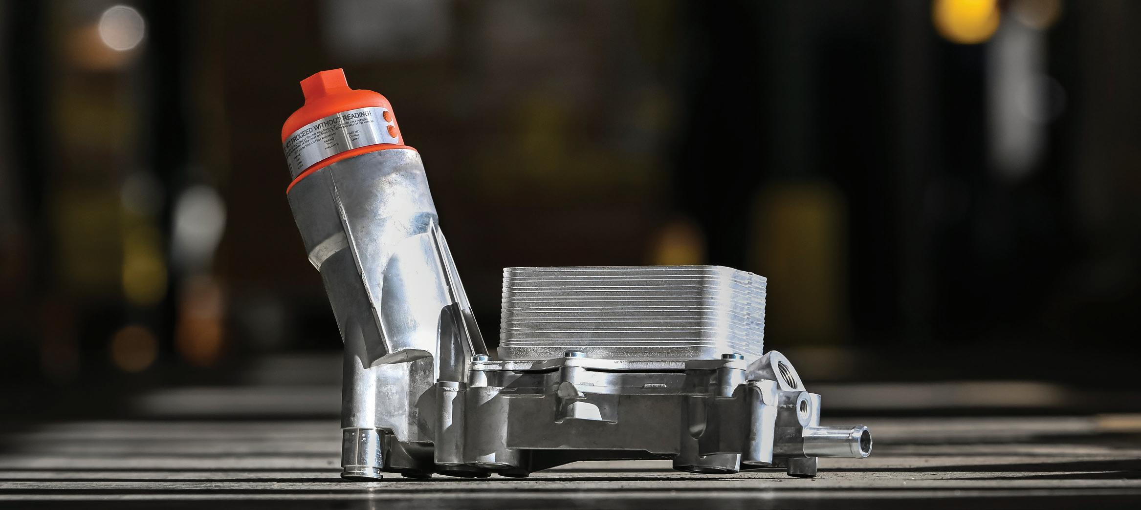
The oil filter adapter on millions of Chrysler, Dodge, Jeep and Ram V6-powered vehicles often leaks oil when its plastic housing warps from harsh underhood conditions. As the plastic eventually degrades from heat and chemical exposure, it can even crack from simply tightening the oil filter cap during oil changes. When it fails, replacing it with an OEM housing could mean the same issues again in the future.
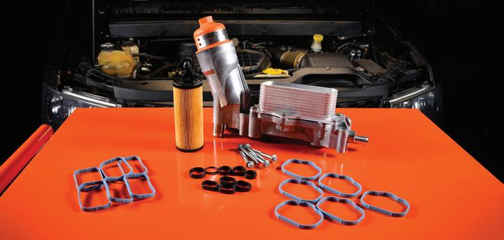
This patented Dorman OE FIX filter housing is made entirely of aluminum for a more durable replacement of the failure-prone OEM housing to help prevent future leaks. The housing comes complete with mounting and intake manifold gaskets for an effective repair. The kit also includes the oil cooler, oil filter element, and oil filter cap to update the vehicle to the latest design.

Patented design - features high-pressure, die-cast aluminum housing construction to more reliably replace the failure-prone plastic housing on specific 2011 and later Chrysler, Dodge, Jeep and Ram vehicles with Pentastar engines
Smarter solution - includes required gaskets, oil cooler, oil filter element and cap, bringing early fitments to latest generation filter specification; see included instructions on filter cap
Trustworthy quality - engineered in the United States and made with durable materials to precise specifications, including premium seals to further help resist future leaks


STARTERS
04 Online Extras
06 Straight Talk
08 Tech Tips
10 Making Sense of the WRAF Sensor’s Operation
With the stringencies of emissions standards increasing, knowing how rich or how lean an A/F mixture truly is, is crucial. Enter the WRAF sensor.
Brandon Steckler
16 Aftermarket Engine Management Systems
The sight of new technology on old iron shouldn’t prompt a technician to run for the door.
Erik Screeden
22 Shop Safety
Tips on avoiding injury and improving efficiency
Mike Mavrigian
30 Suspension Innovations and Alignment Essentials
The evolution of modern suspension and steering: innovations, challenges, and alignment basics
Jeff Taylor
37 Lost in Translation
When life gives you lemons, make lemonade — not Lemon Law.
Brandon Steckler
42 Shop Fire Risks
What technicians need to know about the dangers and differences between EVs and gas-powered engines.
Craig Van Batenburg
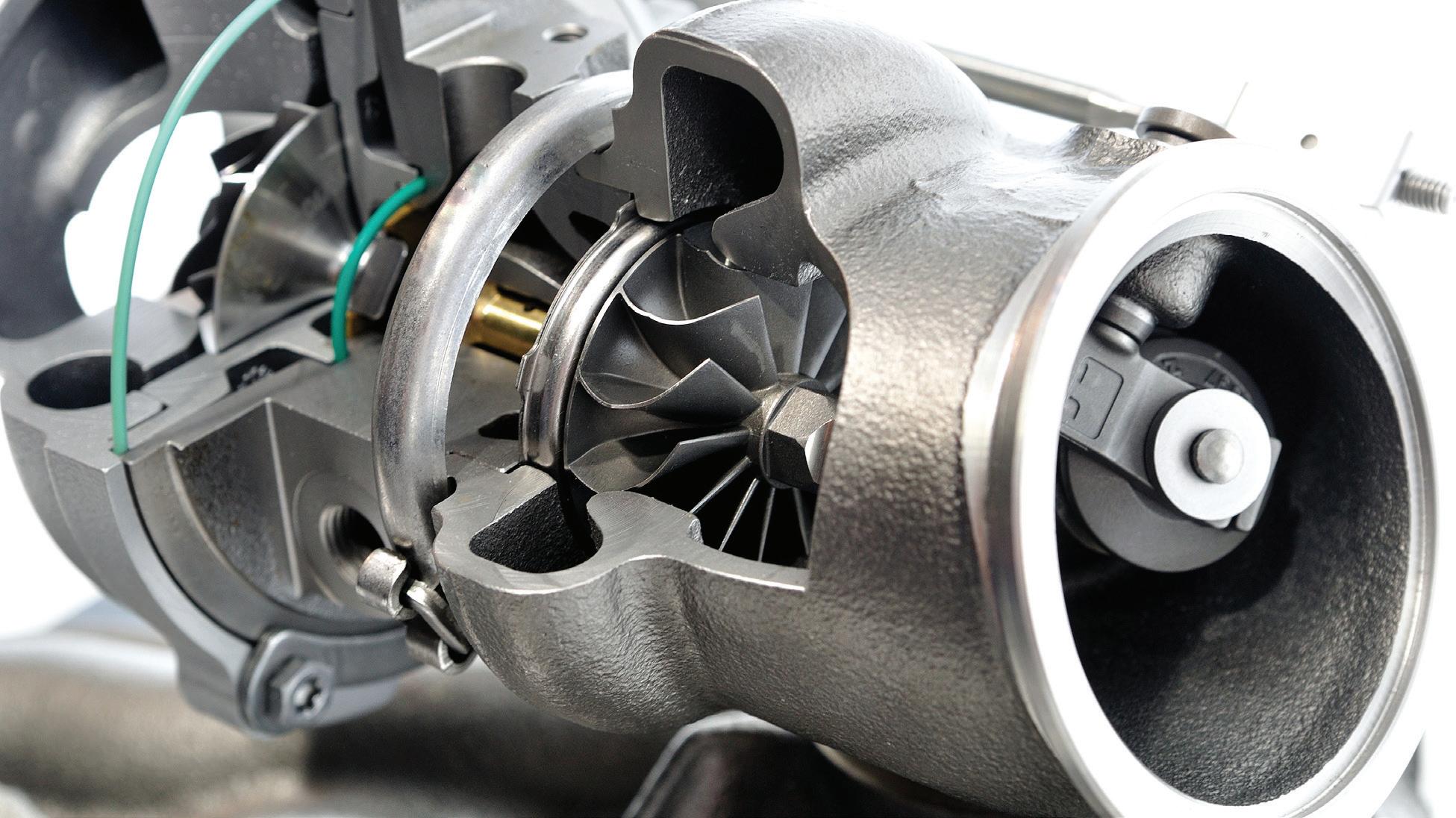
58 The Trainer #159 Forced Induction
Brandon Steckler
ONLINE
TALK SHOP. ANYTIME.
MOTOR AGE IN THE CLASSROOM
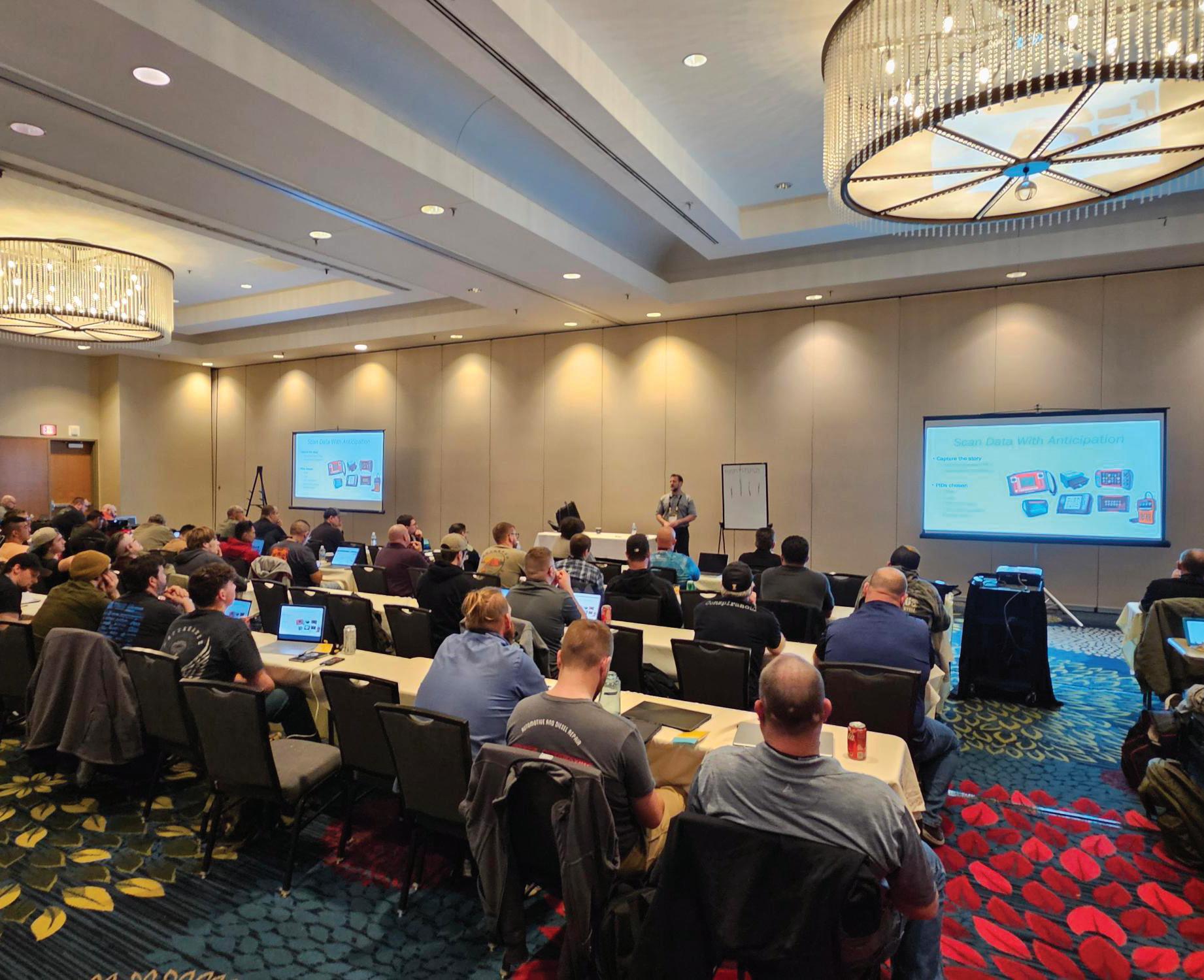
Technical Editor Brandon Steckler once again took his spot in the front of the classroom during Vision 2025, the High-Tech Training & Expo in Overland Park, Kan. Steckler taught a series of in-depth seminars during the conference — and more members of the Motor Age team were on the ground, too! Make sure you’re following Motor Age on all of your favorite social platforms to keep up with the crew. And next time you spot one of our trainers on the road, snap a picture and tag us!
AWARD
BEST YOUNG TECH AWARD
This month Motor Age is kicking off its search for the next Best Young Tech. The award, in its fifth year, is designed to recognize a professional technician under age 35 who is doing good work and is passionate about their career and the industry. Do you know a stellar candidate? Perhaps you’re the standout tech on your team? Fill out the nomination form, or share it with a young technician you believe deserves some recognition. The award is presented during a ceremony at AAPEX and the top prize includes a trip to Las Vegas for the 2025 SEMA Show.

SCAN TO LEARN MORE ABOUT THE BEST YOUNG TECH AWARD!
EDITORIAL
GROUP EDITORIAL DIRECTOR
Chris Jones / christopherj@endeavorb2b.com
EDITOR
Mike Mavrigian / mmavrigian@endeavorb2b.com
MANAGING EDITOR
Joy Kopcha / jkopcha@endeavorb2b.com
TECHNICAL AND MULTIMEDIA CONTENT DIRECTOR
Erik Screeden / escreeden@endeavorb2b.com
TECHNICAL EDITOR
Brandon Steckler / bsteckler@endeavorb2b.com
ASSOCIATE EDITOR
Madison Gehring / mgehring@endeavorb2b.com
CONTRIBUTING WRITERS
Jeff Taylor, Craig Van Batenburg
ART AND PRODUCTION
ART DIRECTOR
Emme Osmonson
PRODUCTION MANAGER
Mariah Straub
AD SERVICES MANAGER
Karen Runion
SALES
ASSOCIATE SALES DIRECTOR
Mattie Gorman-Greuel / mgorman@endeavorb2b.com
DIRECTOR OF BUSINESS DEVELOPMENT
Cortni Jones / cjones@endeavorb2b.com
ACCOUNT EXECUTIVES
Kyle Shaw / kshaw@endeavorb2b.com
Marianne Dyal / mdyal@endeavorb2b.com
Annette Planey / aplaney@endeavorb2b.com
Darrell Bruggink / dbruggink@endeavorb2b.com
Sean Thornton / sthornton@endeavorb2b.com
Diane Braden / dbraden@endeavorb2b.com
Lisa Mend / lmend@endeavorb2b.com
Chad Hjellming / chjellming@endeavorb2b.com
ENDEAVOR BUSINESS MEDIA, LLC
CEO Chris Ferrell
COO
Patrick Rains
CRO
Paul Andrews
CDO
Jacquie Niemiec
CALO
Tracy Kane
CMO
Amanda Landsaw
EVP TRANSPORTATION
Kylie Hirko
BUSINESS STAFF
VP/GROUP PUBLISHER
Chris Messer
PUBLISHER
Andrew Johnson
BUSINESS DEVELOPMENT DIRECTOR, MOTOR AGE TRAINING
Michael Willins
CUSTOMER MARKETING MANAGER
Leslie Brown
AUDIENCE DEVELOPMENT MANAGER
Tracy Skallman
SALES COORDINATOR
Jillene Williams
HOW TO REACH US
ENDEAVOR BUSINESS MEDIA LLC. 30 Burton Hills Blvd, Ste. 185, Nashville, TN 37215

Phone: 800-547-7377
CUSTOMER SERVICE
Subscription Customer Service 877-382-9187; 847-559-7598
MotorAge@omeda.com PO Box 3257 Northbrook, IL 60065-3257
REPRINT SERVICES reprints@endeavorb2b.com
MEMBER OF:


The Basics Remain Relevant
Technicians of all ages may appreciate a refresher course on some fundamentals.
IN THE FACE OF HAVING TO KEEP UP with the ever-rapidly evolving technology spilling out of the showroom floor, it’s easy to sometimes ignore the basics. Considering today’s age of ever-advancing electronic control systems, techs must struggle to stay abreast of often complex diagnostics. That’s obvious. However, many younger technicians enter the industry lacking basic knowledge of thread fasteners, i.e. shank length, thread pitch/count, inch and metric sizing, etc. During component assembly and installation, it’s common for some fasteners to require replacement due to missing, broken, or damaged original fasteners. The need to identify the correct bolt, screw, or nut relies on identifying format (inch or metric), thread diameter, thread count, shank length, tensile strength grade, thread preparation, and more. Depending on the situation, techs may simply order the published size/type listed in the service manual, or revert to readily available aftermarket fasteners. Just because the replacement bolt “seems to fit” does not mean that it’s the correct bolt for the given application. More emphasis needs to be placed on educating young technicians regarding this basic knowledge that is often overshadowed by ever-advancing electronic systems. You may roll your eyes in disdain while
reading this, but if you ask a new tech how to identify and measure a metric bolt, don’t be surprised if you’re greeted with a blank stare. If so, it’s not really the young tech’s fault. He or she simply may not have been informed of the need to understand these basics.
For example, simply understanding thread size for both fractional and metric platforms can help new techs avoid confusion. Thread size involves both diameter and thread spacing. Fractional bolts, for example, are sized (as the term implies) in fractional inch increments such as 5/16, 3/8, 7/16, 9/16, etc. Threads are identified in terms of “threads per inch,” meaning the number of threads per inch of bolt shank length. An example is 5/16x18, representing a bolt that is 5/16” in diameter, with 18 threads along a 1” length. Metric bolt diameters are sized in millimeters, and threads are identified by the spacing between threads. An example is M8 x 1.25, meaning that the bolt diameter is 8mm and the threads are spaced 1.25mm apart.
Of course, this is basic info, but it is surprisingly misunderstood by some, especially some newbie technicians. Consider conducting a brief basic instruction class when new staff enters the shop. It can also serve as a good refresher for seasoned techs as well.


MIKE MAVRIGIAN MOTOR AGE // EDITOR mmavrigian@endeavorb2b.com


OLMSTEAD TOWNSHIP, OHIO –
Corey Evaldi leads his Ohio-based auto shop to greater heights by converting over from pneumatic to MILWAUKEE’s cordless tools, enhancing technician performance, productivity, retention, and safety. The integration of these tools boosts billable hours and reduces maintenance, while eliminating the hassles of air hoses and cords in the shop.
... in a world of instant gratification, MILWAUKEE® has introduced perpetual gratification.
- COREY EVALDI, OWNER: OLMSTEAD AUTO
HOSE TO UNTANGLE


THE ADVANTAGES OF CONVERTING TO MILWAUKEE® CORDLESS or visit https://qr.mke.tl/24bjk
Be Careful With Stainless Bolts
LS Engine Cam Bearing Woes
If you’re faced with a GM LS engine with worn/failed cam bearings, whether you opt to perform the bearing work in house or farm this out to a local machine shop, be aware that this may not be as simple as knocking out the original cam bearings and press-fitting in new bearings.
Over the years and as the LS platform has evolved, you need to be aware that due to factory tolerances for cam bearing bores, a “direct replacement” set of cam bearings may work, or you may end up with too-tight or too-loose bearing fit. After these blocks were cast and machined, the factory then installed cam bearings and honed the bearing IDs to provide the required oil clearance. Once the original bearings are removed, you may need aftermarket bearings that are slightly oversized or undersized. Aftermarket bearing
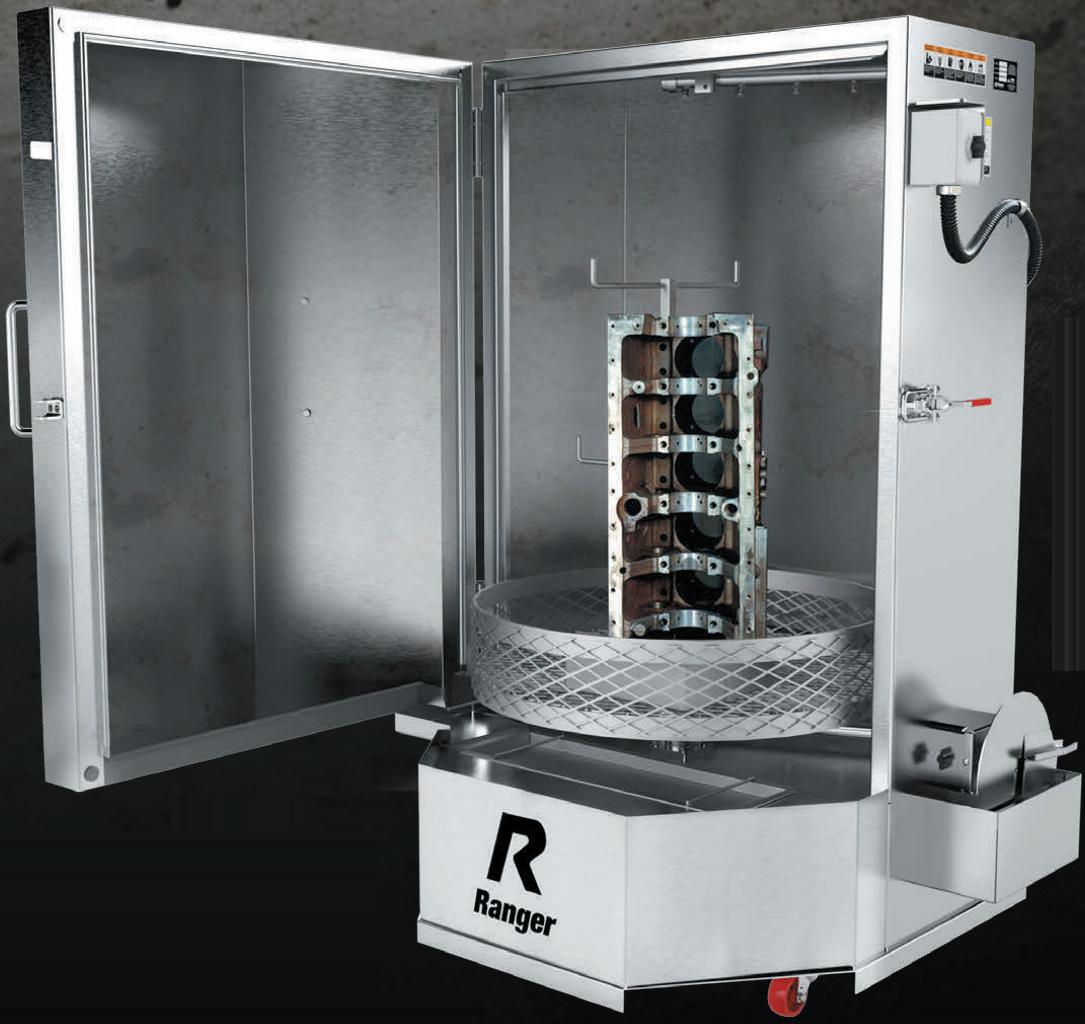
Ultrasonic Cleaning
Cleaning numerous small parts can require lots of time that could otherwise be spent on other things. Rather than standing in front of a solvent tank with a small brush trying to remove crud from tiny crevices, consider buying a small ultrasonic cleaner. While large, professional units can cost thousands, there are some inexpensive units that will get the job done. Depending on size, these can be had for as little as $100 for a toaster-sized unit. Cleaning agents are available specifically designed for ultrasonic cleaners, but a simple mix of distilled
makes offer “block saver” bearings that eliminate the need to re-bore the cam bores. Bearing interference fit to the block has changed as well. While original factory press fit was listed as 0.001-0.0015”, aftermarket bearings are available designed for 0.005-0.007” press fit, providing added insurance against potential spun bearings. You simply need to be aware that replacing cam bearings in a LS block may or may not be a quick and easy task. Cam bores must be accurately measured before ordering replacement bearing sets. LS blocks feature “stepped” bearing bores, meaning that not all bores are the same size. Bore locations 1 and 5 are the same, 2 and 4 are the same and position 3 is different yet. Do not assume that each of the factory bores is machined to a specific size due to the wide tolerance range.
On occasion you may deal with stainless steel thread fasteners. While stainless bolts are less prone to corrosion issues, when threading a stainless steel bolt into an iron block, be sure to apply a lubricant to the threads. (Depending on the application, this may call for anti-seize or a thread locker.)
Especially if installed with speed (impact, air ratchet, etc.), the heat and friction created can result in thread galling, which can make bolt removal extremely difficult.
No 10th Gear
Owners of 2020 Ford Super Duty trucks equipped with either the 6.2L or 7.3L diesel engine with a 10R140 transmission may complain about the loss of 10th gear, harsh shifting and overall poor shift quality. DTC P07F7 may be stored in the PCM. This may be due to the sleeve in the CDF clutch cylinder shifting axially, causing hydraulic circuit leaks. The fix: replace the CDF clutch cylinder.
water and Dawn dishwashing liquid works in a pinch. The cleaning is performed with a combination of heat and ultrasonic frequencies. Drop the parts in, let the unit run, remove, rinse with cold water and you’re done. Don’t let the DIY/cheapo prices fool you — there are units out there that work amazingly well. In some cases — depending on how filthy the parts were to begin with — you may need to run an additional cycle. The cool thing is that you can turn your attention to other work while the parts are being cleaned.
GM Oil Filters
GM has changed their spin-on oil filter tightness for 2020-2024 vehicle applications, as there have been many reports of leaks between filter gasket and mounting surface, and too-easy to remove filters during service. After applying a film of clean oil to the filter gasket, GM now specifies one full turn of the filter (approximately 10 ft-lb).


Making Sense of the WRAF Sensor’s Operation
With the stringencies of emissions standards increasing, knowing how rich or how lean an A/F mixture truly is, is crucial. Enter the WRAF sensor.
BY BRANDON STECKLER
LIKE ANYTHING ELSE IN THE WORLD of diagnostics and driveability in particular, a sound understanding of the component’s functionality is an absolute must if you want to maintain accuracy and efficiency. Why not begin with the wide-range air/ fuel (WRAF) ratio sensor? After all, it’s responsible for the tight control of today’s fuel injection control systems.
The problem I have found in my years as a technical instructor and even a technician in the field is that many lessons are taught at a level that is not easily retained. What I mean is, that many lessons are delivered at a level that most technicians are not ready to receive. Now, there is nothing wrong with that, but if the idea is retention, it doesn’t work very well in my opin-
ion. It forces memorization and that has never been a strong suit of mine, at least.
So, to bridge the gap between the intricate lessons being taught and what most technicians are capable of retaining without memorization, I will attempt to describe the WRAF’s functionality so that it simply makes sense and serves techs well where it counts the most, in the trenches.
The Zirconium-Dioxide Oxygen Sensor
To describe the WRAF in a fashion that makes sense to most technicians, I’d like to begin with the description and operation of the HO2 sensor that manufacturers have leveraged for decades, the Zirconia oxygen sensor.
I’ll begin by saying that Zirconium possesses a characteristic that allows the sensor to be a galvanic device (meaning, it creates its own voltage). The Zirconium oxygen sensor has a Nernst cell that compares the indifference of oxygen content from the exhaust’s stream to that of the atmosphere. Just like a balance scale (Figure 1). It does this through a reference chamber that is linked to the air outside the exhaust pipe. (Yes, it’s important to keep the oxygen sensor clean and free from leaking oil and such.)
The goal of the oxygen sensor is to find equilibrium of oxygen molecules from the exhaust stream to the atmosphere (Figure 2). What I mean by that is (for example) under rich conditions, the content in the
exhaust stream lacks oxygen. Under these conditions, the atmospheric oxygen content is higher than the concentration in the exhaust stream. Because the sensor seeks equilibrium, the oxygen sensor will migrate oxygen from the reference cell to the Nernst cell by pulling the external oxygen molecules through the Zirconium. As the oxygen molecules migrate through the Zirconium, a voltage potential is created (the reason we see nearly 900mV on the signal circuit under rich conditions) (Figure 3)
Now, under lean conditions, there is an abundance of oxygen in the exhaust stream. Said another way, the oxygen content in the exhaust stream is similar to the concentration in the atmospheric reference.
As a result, the oxygen sensor has no need for much oxygen migration (to find equilibrium) and the lack thereof creates very low voltage potential (the reason we see nearly 100mV on the signal wire during lean conditions) (Figure 4).
Limitations of the HO2 Sensor
So, now that we have simplified the functionality of the HO2 sensor, let’s focus on how that plays a role in traditional/older computerized fuel injection strategies. I’ll begin by stating an important but typically understated fact: Computers are not smart. They are simply programmed to respond to inputs, and can do so very swiftly and accurately, when functioning properly. The response is the feedback system used to maintain the operation of the catalytic converter. And to do so supports not only adequate driveability but also clean tailpipe emissions.
The HO2 sensor is just an input. It simply indicates a lack of, or abundance of oxygen (rich or lean). When the ECU sees a low voltage oxygen sensor signal (like 200mV), the ECU will increase injector pulse width to deliver more fuel. This is what we refer to as positive fuel trim. The ECU will continue to increase injector pulse width until it sees the input it desires to see: an HO2 sensor voltage increase above 450mv, the “lean/rich switch point.”
The opposite also holds true. When the ECU sees a high voltage oxygen sensor signal (like 800mV), the ECU will decrease injector pulse width through negative fuel trim. The ECU will continue to decrease

the injector pulse width until it sees the input it desires to see: an HO2 sensor voltage decrease below 450mV, the “rich/lean switch point”.
Again, to maintain this tight control


FIG. 4 A lean exhaust stream is abundant in oxygen. As a result, the migration from atmosphere to Nernst cell isn’t necessary and low voltage will be generated on the HO2 sensor signal circuit.
FIG. 1 In a simplified explanation, the HO2 sensor’s Nernst cell acts like a balance scale for oxygen content, comparing what is found in the exhaust stream to what is referenced from the atmosphere.
FIG. 3 A rich exhaust stream will be deficient in oxygen and the cell will allow oxygen to migrate through its zirconium construction to find that balance. This creates the higher voltage we see on the HO2 sensor signal circuit.
FIG. 2 The Nernst cell seeks equilibrium. As a result, a differential in oxygen content from internal to external of the exhaust will cause the oxygen molecules to migrate. The oxygen will be pulled across the Zirconium barrier.
means to maintain a tight window around the stoichiometric air/fuel ratio of about 14.7 parts air to 1 part fuel (by weight), keeping the catalytic converter functioning. And this is where the limitation of the Zirconium HO2 sensor surfaces.
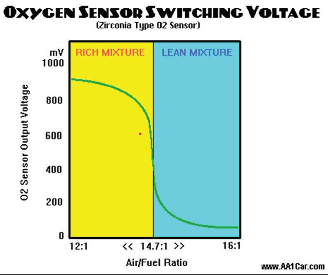
Take a look at this chart (Figure 5). Under rich conditions (a/f ratios lower than 14.7:1) the HO2 signal immediately switches to a high-voltage output. And on the lean side (a/f ratios above 14.7:1) the sensor signal immediately switches to a low-voltage output. The sensor has no ability to indicate just how rich or how lean the exhaust gas is — only if it’s richer than stoichiometry or leaner than stoichiometry. It’s for this reason we have been told for decades that a catalyst can only function at stoichiometry, and that isn’t entirely accurate.
The whole truth is ECUs can only see what the HO2 sensor shows them (rich or lean). I equate this to attempting operation of a radio-controlled airplane. So long as the plane doesn’t duck behind some trees, and I can see it, I can maintain control of it. But if it goes out of sight, I can’t maintain control. Very similarly, if the a/f ratio deviates too far away from stoichiometry in either direction, there is no way to know just how far away from stoichiometry the a/f ratio is because the HO2 sensor cannot display it (loss of fuel control and catalyst functionality).
The WRAF Ratio Sensor
So, with the increase in sensor technology comes the WRAF. In my experience, this highly sophisticated device is quite difficult for most technicians to understand in the way it’s typically presented. For this reason I wish to simplify its functionality with some analogies.
I’ll begin by stating that the WRAF is like having two devices built into one unit. The traditional functioning HO2 sensor properties still exist. As the exhaust oxygen content is being sampled, the sensor will output a signal amplitude that correlates with oxygen concentration.
However, the goal of the ECU is to monitor that signal and attempt to keep the signal voltage at 450mV.
The second part of this device is the Nernst cell which has an amperometric property, meaning it uses current flow to perform some work. Its job is to move oxygen molecules in and out of the Nernst cell. But I will ask that you think of this cell with an easy-to-imagine analogy.
Picture a man with a shovel. His job is to use the shovel to move oxygen molecules in and out of the Nernst cell. If the HO2 signal increases above 450mV (indicating a lack of exhaust oxygen content or rich condition) the man with the shovel will move oxygen into the Nernst cell to reduce HO2 sensor signal voltage (again, the goal is 450mV).
If the HO2 sensor signal voltage drops below 450mV (indicating an abundance of exhaust oxygen content or lean condition) the man with the shovel will move oxygen out of the Nernst cell to increase HO2 sensor signal voltage and attain the goal of 450mV.
The ECU watches the man with the shovel and its job is two-fold:
• Determine the direction the man is shoveling the oxygen molecules.
• Measure how hard he is working.
With these two primary objectives, the ECU can not only determine “rich” or “lean” (like the Zirconium oxygen sensor), but can now determine “how-rich” or “how-lean” the exhaust gas is.
Data Extraction
The WRAF sensor’s output to the ECU varies depending on which side of the ECU is being monitored (OBD2 global vs. enhanced data). It can be a voltage signal, a bi-directional amperage signal, or both. And to be honest, the sensor signal’s amplitude means different things on different vehicles.
For instance, stoichiometry is indicated on a Honda when the sensor signal is at 2.2V, but on a Toyota at 3.3V. Then, you have Subaru whose sensor may indicate 2.5V at stoichiometry. I can under-
stand why so many technicians get off in the weeds about these devices. It’s all very confusing.
With that, I almost never look at those values. I let the computer do the work. Those values will correlate with the ECU’s programming to indicate an air/ fuel ratio. I simply look at the end result — because that end-result is the same on every OBD2 certified internal combustion engine on the planet. This chart below shows the relationship of current values to Lambda and that is exactly what I’m after (Figure 6).
Lambda is the equation that compares the actual measured air/fuel ratio to the ideal air/fuel ratio (for the fuel being used). A lambda value of 1.00 is stoichiometry. A value exceeding that represents an abundance of oxygen and below that, a lack of oxygen. The takeaway is, it does not matter which vehicle, which fuel is being used, or which professional scan tool you are leveraging.
The chart shows exactly what the man with the shovel was telling the ECU. As the sensor detected a rich exhaust content, the amperage output as a negative value (shoveling oxygen into the Nernst cell).
The harder and faster the man shoveled, the further the amperage signal deviated negatively from 0 mA (0 mA is “stoichiometry” — how convenient.) (Figure 7)
The opposite holds true as well. As the sensor detected a lean exhaust content, the amperage output as positive (shoveling oxygen out of the Nernst cell). The harder and faster the man shoveled, the further the amperage signal deviated positively away from stoichiometry). If we go back to the analogical perspective, this would now be like operating a drone with an on-board camera. We can pilot it far out-of-sight and still maintain great control. The WRAF allows the ECU to accurately detect a/f ratios as lean as 24:1 and a rich as 11.5:1
In Summary
Heated exhaust gas sensor signal feedback
continues to govern the operation of the computerized fuel injection system, and for the same reasons. With the increase in sensor technology and computer processing capability, the goal of the system is no longer to maintain stoichiometry and ensure catalyst functionality.
For example, if the vehicle in question suffered from the potential to produce NOx, we realize as technicians, high temperatures are the root cause of NOx production. NOx production becomes an issue in temperatures exceeding 2500 degrees Fahrenheit. If an ECU was programmed (under certain operating conditions) to create an air/fuel ratio below 14.7:1, that richer mixture will serve to quench the combustion chambers, lowering the temperature and reducing overall NOx production.
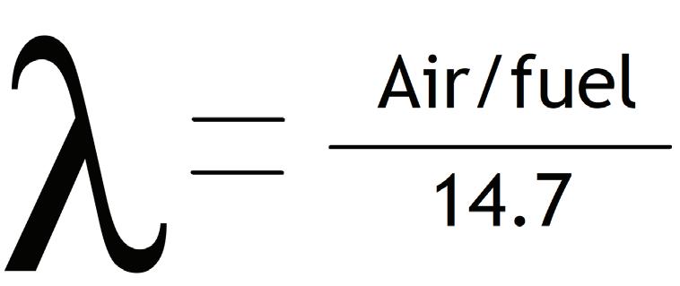
The equation of Lambda represents air/fuel ratio in regard to stoichiometry as Lambda 1.00. Lambda (being the “air-factor”) represents an abundance of oxygen, increasing in concentration with Lambda values above 1.00, and a lacking of oxygen with Lambda values below 1.00. This representation is the same for every internal combustion engine out there, regardless of the manufacturer.
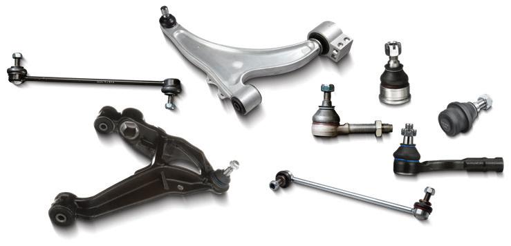
Delphi aftermarket steering and suspension parts undergo rigorous dimension, material, durability and performance tests.


Our engineers are driven to ensure that our parts meet OE form, fit and function specifications so you can install them with confidence.
your Delphi Rep to learn more.


FIG. 6
FIG. 5 The Zirconium oxygen sensor responds very rapidly to changes in exhaust gas oxygen content but only in a very narrow window of stoichiometry. For this reason, fuel control must stay within that same narrow window of operation. AA1CAR.COM
On the flip-side, there is no need for a rich mixture during light-cruise conditions because torque production is not required. If an ECU was programmed to increase the air/fuel ratio above 14.7:1 this would serve to boost fuel efficiency.
Through the eyes of the post-catalyst HO2 sensor (sometimes a post-catalyst WRAF is utilized in new vehicles) the remaining oxygen content will indicate whether the catalyst is still functioning. As long as the catalyst is doing its job, the

vehicle will remain emissions-compliant. The goal now is to monitor the operation of the catalyst and take the air/fuel ratio as far away from stoichiometry as needed to accomplish other goals.
Taking the time to wrap our heads around the following is absolutely crucial to accuracy and efficiency as a technician in today’s shop:
• The functionality of the Zirconium-dioxide HO2 sensor
• The functionality of the wide-range air/ fuel ratio sensor
• The strategies of both new and past ECU driven fuel injection systems
This allows anticipation during testing and the ability to capture and view preliminary scan tool data (right from the driver’s seat) so time isn’t wasted testing unnecessarily. But don’t take my word for it. Take the time to try it out for yourself and you will be glad you did!


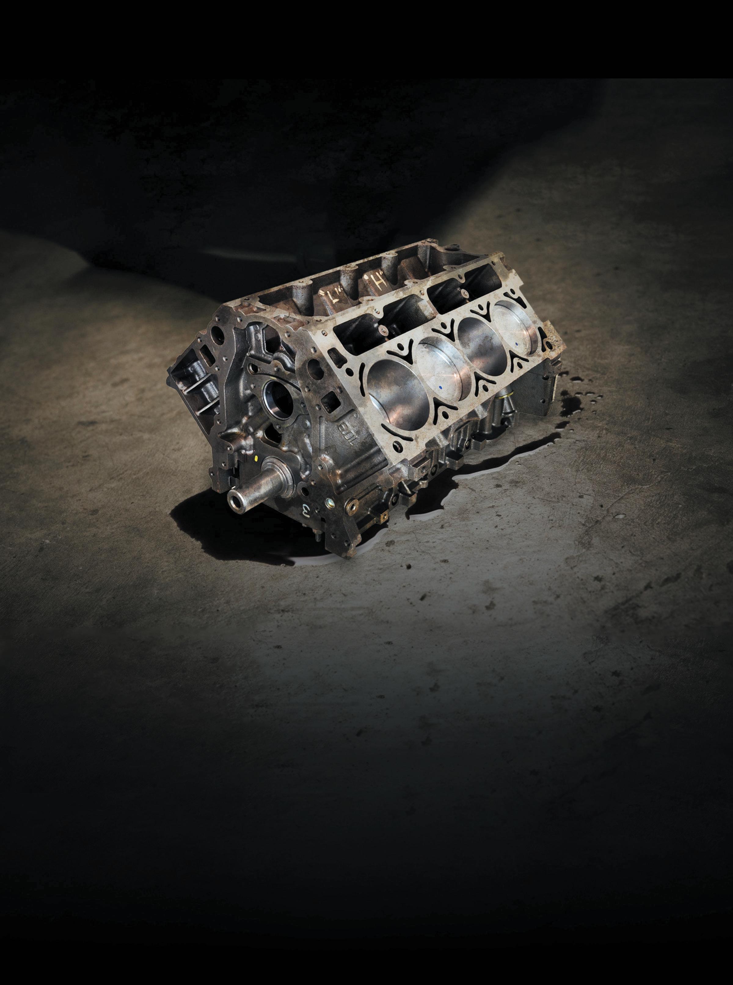
FIG. 7: This chart shows the correlation between both positive and negative current value outputs from the WRAF, along with the Lambda values they represent. Instead of focusing on the mA or voltage values, focus on the end-result, the “Lambda” values displayed on the scan tool.


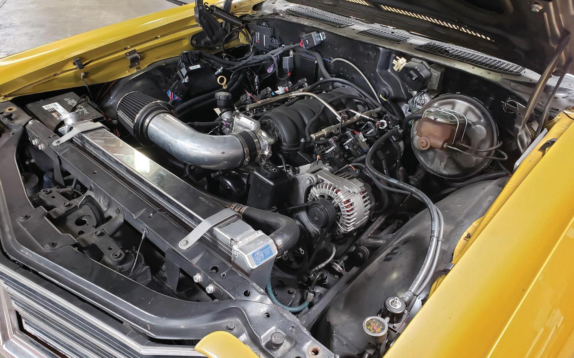
Aftermarket Engine Management Systems
The sight of new technology on old iron shouldn’t prompt a technician to run for the door.
BY ERIK SCREEDEN
WE HAVE ALL SEEN IT. That loyal customer who diligently brings their family workhorse in for service, on time, every time. They follow manufacturer-suggested service intervals and never question a needed repair or suggested service. Then one day they drop it on you. Not only do they have their tried-and-true daily driver, but they also have their weekend cruiser. Maybe it’s an early ‘50s Packard convertible, a ‘70s GM A-Body, a first Gen Mustang, or even some Malaise-era land yacht.
But it doesn’t matter, because you are “the one.” The only one that they want to work on their “baby.” As a shop owner, service manager, or technician, it’s a nice feeling to provide such an exemplary service that it results in so much trust. So, you agree, but when the day comes to bring it in they add one more small tidbit of information — this vehicle is no longer stock — and that uneasy feeling sets in.
Unless you work at a business that specializes in classic or customized vehicles, or are an enthusiast yourself, often you are not going to go out of your way to attract business in that niche market. Afterall, if car counts and invoice totals are up, why rock the boat? It’s no secret that older vehicles
can be more difficult to source parts for and can be more time consuming to work on. Layer that with the complexity of aftermarket components, especially on the engine management side of things, and it can be enough to scare a technician off — but it doesn’t have to be.
A Look Into the Past
There has been a specialty aftermarket almost as long as there has been an automotive industry. Adding aftermarket components to a vehicle in order for it to accelerate harder, handle better, or stop faster is nothing new or foreign to most technicians. Even swapping later model engines, or just induction systems into
GM LS platform in a second gen A-Body wagon using an Edelbrock Pro-Flo 4+ EFI engine management system. EDELBROCK
older vehicles is nothing revolutionary. All the way back as far as the early ‘90s, many a third-generation GM F-Body or C4 Corvette sacrificed their L98 powerplant and 700r4 automatic transmission for somebody’s street rod or restomod project. Though often incorporating an aftermarket harness, some programming to bypass vehicle anti-theft, tuning for any performance upgrades, and maybe removal of some unused emissions componentry, in the early days of EFI swaps the factory ECM was typically retained. This allowed not only closed loop operation, but the use of factory scan tools for retrieval of DTCs and viewing of live data if available. What they did not allow for though was a lot of flexibility.
The early days of EFI were hindered by slow processors, narrow band oxygen sensors, and the inability to truly react quickly to all the inputs coming into the controller. Instead, the ECM was relying on pre-mapped fuel and timing information in many phases of operation, such as when the vehicle neared WOT. Then there was tuning for performance adders. From simple bolt-on upgrades to larger displacement builds, even forced induction at best often involved hours of chassis dyno time where tunes had to often be burned onto removable EPROMs. Worse, if you didn’t have anyone that could program near you, it involved trial and error all while shipping the EPROM back and forth through the mail. Rudimentary technology hindered performance, limited overall power output, and sacrificed driveability. But it didn’t stay that way forever.
Technology Has Evolved
Really ramping up in the last 15 to 20 years, rapid evolutions in technology have allowed the industry to rethink the way it handled aftermarket engine management. Companies like Edelbrock, Holley, and others started developing aftermarket engine management systems that were able to allow the professional and hobbyist alike to easily install EFI into older applications.
With the development of self-contained aftermarket EFI throttle body systems that simply bolted in place of a standard 4150 style square bore carburetor, EFI installations exploded. Programming and modification for performance builds have always been there, but now the benefits of EFI could truly be scaled out to many different applications. With the installation of a suitable fuel system, a few sensor inputs, and finding reliable powers and ground, these systems are easily installed and have an incredible amount of adaptability. Eventually the popularity of swaps like the GM LS/LT platform, Dodge Hemi, and Ford Coyote pushed the aftermarket technology even further. The inclusion of sequential port fuel injection into aftermarket EFI systems and options like dual wideband air fuel ratio sensors really increased the precision at which the fueling strategy could be controlled.
One of the biggest selling points on modern aftermarket engine management systems, aside from the obvious benefits of EFI, is the ability for many modern systems to self-learn. While obviously not suited for every application, self-learning capabilities on many aftermarket EFI systems make EFI conversion more widely adaptable to enthusiasts across the industry. Aftermarket EFI companies have differing amounts of control offered to the user, but most have a self-learning capability that, with a few initial inputs when the system is set up, will allow the system an initial fuel and timing map of which to build. From there, once the vehicle reaches operating temperature, the system will constantly be adjusting the fueling strategy as the vehicle is driven through different phases of operation. The pre-programmed initial tables, plus the self-learning capabilities of these systems, generally are enough for the vehicle — even with a moderately modified engine — to have the ability to be safely street driven with good part throttle response, adequate idle, and safe wide open throttle performance. Often even more advanced levels of control and input are offered to
the user who really wants to fine-tune for optimal performance.
Where Things Can Get Sticky
Any engine management system, just like any other system in a modern vehicle, regardless of OE or aftermarket, is going to assume the information it’s being told is accurate. A controller takes information in and does whatever the programmed software inside it tells it to do: If inputs A, B, and C tell me this, then I will command output X to do that.
If the engine controller is either being fed inaccurate information from one of its inputs or is receiving accurate information but was set up with incorrect base programming to interpret that information in an accurate manner for the actual engine specifications in the vehicle, then an undesirable result will occur.
The amount of engine performance data available to the technician will vary by the EFI system that is installed. Most modern aftermarket EFI systems have a user interface either built into the system’s harness, or available as a tablet or phone app. That user interface is what will give the user the ability to not only monitor live data, but also log data, and in most instances allow changes to the learned data that is taking place. Some EFI systems will also allow the user to interface with a laptop to make more detailed changes, or share data logs and tuning files, but that functionality is typically not needed for basic system diagnostics. The specific data PIDs available will vary by manufacturer but the basics like loop status, desired versus actual air/fuel ratio, short- and long-term fuel trim, engine coolant temperature, intake air temperature, engine load, engine speed, fuel pressure and more, are generally available. What is at times not available are diagnostic trouble codes, so while these systems do a good job of laying out data in a manner that is easily understood, it is important for anyone working on these systems to have a firm grasp of what they are looking at. Talking with David Page,
product panager, forced induction, EFI, and electronics for the Edelbrock Group, he says, “Familiarize yourself with ‘normal’ readings from all of the sensors. Whether the system uses a laptop interface, has a handheld device or app, or has some type of dashboard, make yourself a checklist of sensors that you can monitor at key on, and then again with the engine idling, and again at whatever rpm and load point that the symptom exists at.”
Keeping Everything in Front of You
One of the biggest reasons for the popularity of aftermarket EFI is its effortless driveability in a wide variety of conditions. The reason for that ability for the system to adapt to various conditions, temperatures, and elevations so easily is its closed loop operation, just like you would see on any OE EFI system. The difference is the main concern of an OE EFI system is to get that air/fuel ratio as close to, and keep it as close to, that magical 14.7:1 stoichiometric ratio as possible — to keep the catalytic converter operating at peak efficiency. Since aftermarket EFI systems are generally not concerned with catalyst efficiency, they often allow the user to select a more advantageous target air/fuel ratio and do so across multiple phases of operation. Closed
loop operation is made possible in aftermarket EFI, by a variety of inputs, but at the heart of those inputs is the wideband air/fuel ratio (AFR) sensor. The wideband sensor will sample the exhaust gases and in turn control injector pulse in order to keep the vehicle as close to the desired AFR as possible.
An Achilles’ heel to these systems lies in the fact that the total fueling strategy is dependent on the accuracy of the AFR sensor being used. Unlike many modern OE systems that are fueling multiple banks, some aftermarket EFI applications, for cost and simplicity, may only use one AFR sensor. So, on an engine with multiple banks the EFI system is strategizing its fueling calculation based on information it’s getting from just one bank, and it’s something the technician needs to be aware of. Under optimal conditions that doesn’t pose a problem, but if failures happen on the unmonitored bank, such as a leaking injector on a port fuel-injected EFI system. or false air leaking into an intake manifold runner, that loss of comparability can make driveability diagnostics a bit more challenging — just like the early pre-OBD II days of multi-port fuel injection.
Also, regardless of the number of sensors used, choosing an engine combina-
tion that is “friendly” to fuel injection is critical when using many self-adjusting aftermarket EFI systems. For instance, cam profiles cut on to narrow a lobe separation angle can wreak havoc on a speed density EFI setup that is self-adjusting, because of the low and inconsistent vacuum that is created. Fully tuneable systems offer a bit more flexibility in this department.
Page at Edelbrock says, “With a fully tunable speed density system like a FAST XFI 2.0 or XFI Sportsman, there are no limitations on Camshaft duration, lobe separation, or idle manifold vacuum. The tuner or calibrator simply scales all of the 3D tables according to the amount of vacuum the engine makes at idle. From here, the calibration process is no different than an engine with high idle vacuum.”
Like tackling any engine performance and driveability issue, it is important to do your research and learn exactly how the system operates. With any diagnostic process, understanding vehicle service information before starting down a diagnostic path is a key component for diagnostic success.
Another common failure in these systems is the loss of accuracy in the AFR sensor itself. A wideband AFR sensor is able to accurately determine air/fuel ratio across a much larger range than a typical narrowband sensor. Just like their narrowband sensor counterparts, a wideband AFR sensor utilizes a Zirconium dioxide ceramic, however the wideband AFR incorporates a pumping cell that adds or removes oxygen to maintain a balance. It’s this addition or removal of oxygen into that cell that the ECM is monitoring to determine the AFR. Remember these sensors live in an unforgiving environment — high exhaust gas temperatures, unburned fuel, and other chemicals such as oil and coolant all degrade a sensor’s accuracy over time. Wideband AFR sensors are calibrated as part of the manufacturing process in a controlled environment by utilizing the placement of a resisitor in the signal circuit to maintain
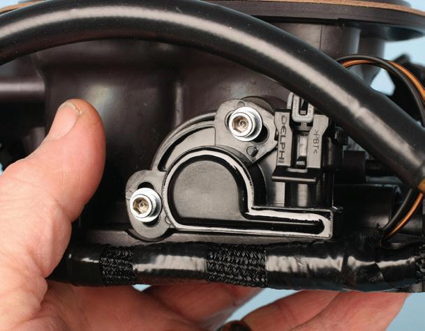
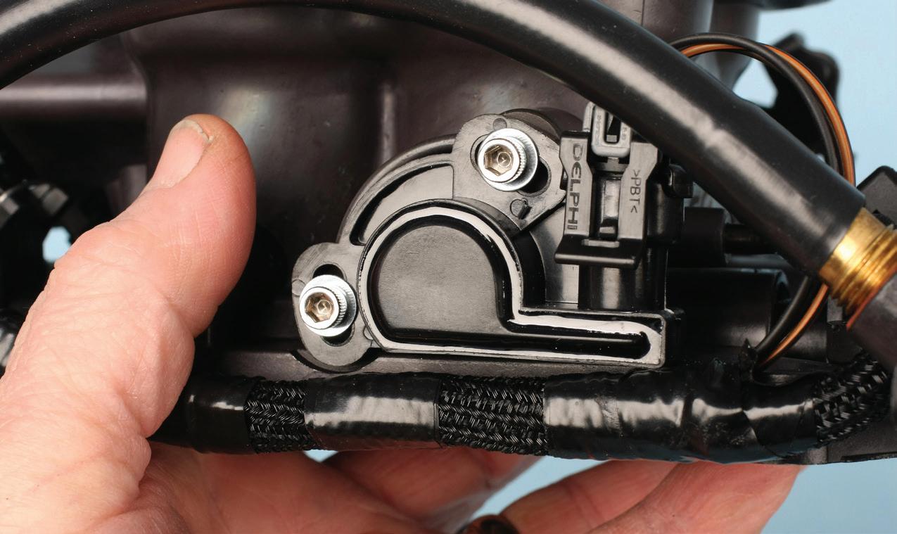
AFTERMARKET EFI does require various inputs so the controller can accurately determine things like appropriate fueling, timing strategy, and even transmission control. Seen here, just like many OE applications, throttle position sensors can be adjustable. It’s important to not overlook proper system setup when trying to get to the bottom of driveability complaints or system faults.
a predetermined set point in each sensor manufactured. Wideband AFR sensors are extremely accurate when leaving the factory, but that accuracy diminishes over time with use. The rate of that decay in accuracy varies depending on its operating environment. While determining whether a sensor is capable of reacting to changes in exhaust gas composition is straightforward, the ability to verify the accuracy it’s maintaining that AFR at can be a bit more challenging.
OE systems often give the technician the ability to use comparative values to infer how accurately an AFR sensor is operating. Being able to take a relational look bank-tobank, as well as using downstream sensors to monitor catalyst operation allows the technician to gain an understanding of how “in control” the fuel system is. On an aftermarket EFI system, especially one utilizing only one AFR sensor, it’s much more difficult to determine what the ECM really believes to be true. Chances are, the whole reason you are seeing this vehicle is based around a driveability concern the owner could not figure out. Being able to compare to a known good will be instrumental in quickly and efficiently diagnosing the customer’s concern. While most shops outside of those who perform engine tuning don’t have a stand-alone wideband setup, many shops do have access to a five-gas analyzer.
The five-gas analyzer gives the user detailed information about the gasses exiting the exhaust. Carbon dioxide, oxygen, carbon monoxide, hydrocarbons and nitrogen oxides are all byproducts of the combustion process, and their specific amounts present tell us a lot about how efficiently an engine is operating. While many technicians think about a five-gas analyzer in the realm of emissions testing, its ability to break down the combustion process makes it instrumental in engine performance diagnostics as well. In the instance of needing a comparative measure, a five-gas analyzer in conjunction with a lambda calculator (which can easily be found online), is a great way to measure
the accuracy of the wideband AFR sensor in the system. The lambda calculator allows the technician to input the values for the carbon dioxide, oxygen, carbon monoxide, hydrocarbons and nitrogen oxides directly from the analyzer’s display into the calculator to generate a lambda reading. That reading can be used to directly compare to the vehicle and either confirm or eliminate a faulty AFR sensor diagnosis — assuming all other variables are within specification.
And lastly, making sure the aftermarket EFI system is correctly installed on the vehicle is an important but all too often overlooked step. These systems need to be installed per manufacturers’ guidelines in order to operate correctly. Common errors include insufficient power sources and bad grounds.
Page from Edelbrock says, “A ground is not a ground. This is a difficult concept for newcomers to EFI systems to accept. For operating lights, electric motors like fuel pumps and fans, etc, using body or chassis grounds is fine — though still not ideal. When dealing with the signals that the ECU is sending and receiving at very high frequency, a clean dedicated ground path to the battery negative terminal is crucial. We, and most EFI manufacturers that I am familiar with, have bold, overt
messages throughout all installation guides and documentation directing installers to only connect the main ground leads from the EFI harness directly to the battery negative terminal.”
If the live data you are viewing does not seem right, take a hard look at sensor placement before going further in your diagnostics. It’s not uncommon for the installer to try to locate something like a coolant temp sensor in a convenient or visually pleasing location rather than where directed by the manufacturer’s in-
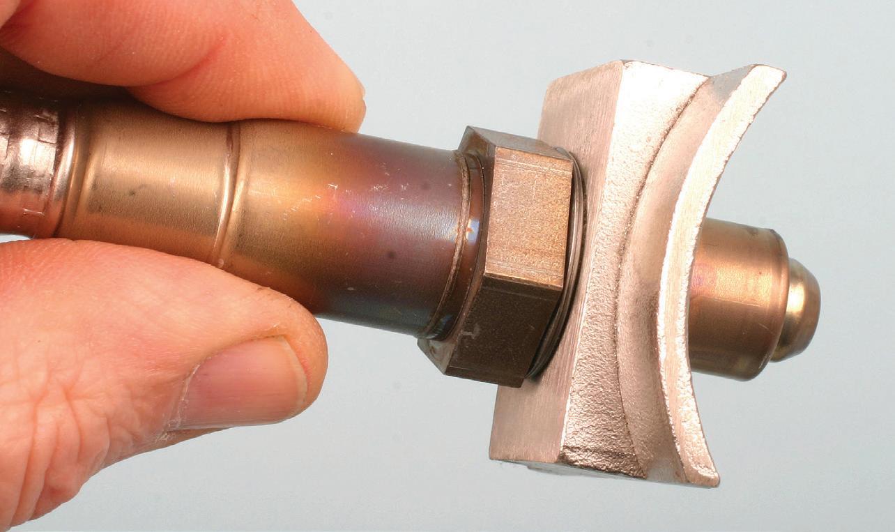
ANY EFI system relies on accurate feedback information on oxygen content in the exhaust to determine proper fueling. Many companies offer adapters to allow the installation of an air fuel ratio sensor into the exhaust. While they work when perfectly sealed, it’s a good best practice to have a proper bung welded into the exhaust to ensure accurate sensor measurement and operation.
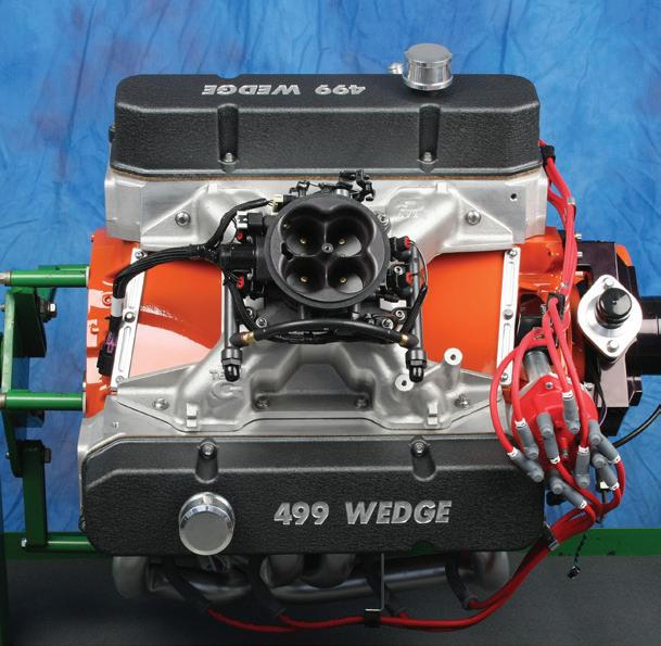
499CID CHRYSLER B engine with an older Holley Terminator EFI setup. Aftermarket throttle body injection is a popular upgrade for enthusiasts because the systems are more self-contained than a port fuel injected option. This allows the vehicle to maintain a more “stock” look.
stallation instructions. It might be intake air temperature sensors not installed in the right location to deliver accurate temperature information, or MAP sensors not supplied with true manifold vacuum. Or there are vacuum leaks that have not been addressed, incorrectly located air/fuel ratio sensors or exhaust systems that leak or are not long enough to quell any fresh air reversion into the system.
Page at Edelbrock says this is an often overlooked issue. “The leak does not have to be upstream of the sensor to be a problem as the exhaust is pulsing more than you realize, pulling in a little fresh air to the sensor’s gas sample.”
Slip-in collectors often don’t seal tight enough, zoomies and a turn down off the collector are not long enough, the exhaust system size, design, and condition are vital yet an very often overlooked part of the equation. Just like days be-
fore when the unacquainted immediately went to making carburetor idle speed, mixture, and jetting changes at the first sign of trouble, folks today are quick to condem things like inputs, injectors, and the controller itself without doing their due diligence with the basics on the installation. Remember, Occam’s Razor principle tells us the simplest explanation is usually the right one.
The great thing about many of these systems is once the root cause of a problem has been determined — and if that issue is one of the system inputs — often times that componentry is available both through the system manufacturer as well as local parts suppliers. Many aftermarket EFI companies use off the shelf componentry that is readily available in the aftermarket. That makes servicing the problem — once the failure is diagnosed — a painless process.
The Juice Can be Worth the Squeeze
Because the benefits of EFI are numerous, the specialty aftermarket likely will continue to see considerable expansion in the realm of aftermarket EFI offerings. Because of that, availability will increase as technology and competition will continue to keep these systems priced at an affordable level.
The law of averages states that sooner or later you very well may have a customer that asks you to help keep “their baby” running smoothly so they and their loved ones can enjoy it. In business we never want to have to say “no,” and I hope that with a little bit of research and understanding you will have the confidence to tell that valued customer “yes.” Because at the end of the day, the more value you can leverage toward that positive customer experience, the more likely that customer will keep coming back to you for all their automotive needs for years to come.


Shop Safety
Tips on avoiding injury and improving efficiency
BY MIKE MAVRIGIAN
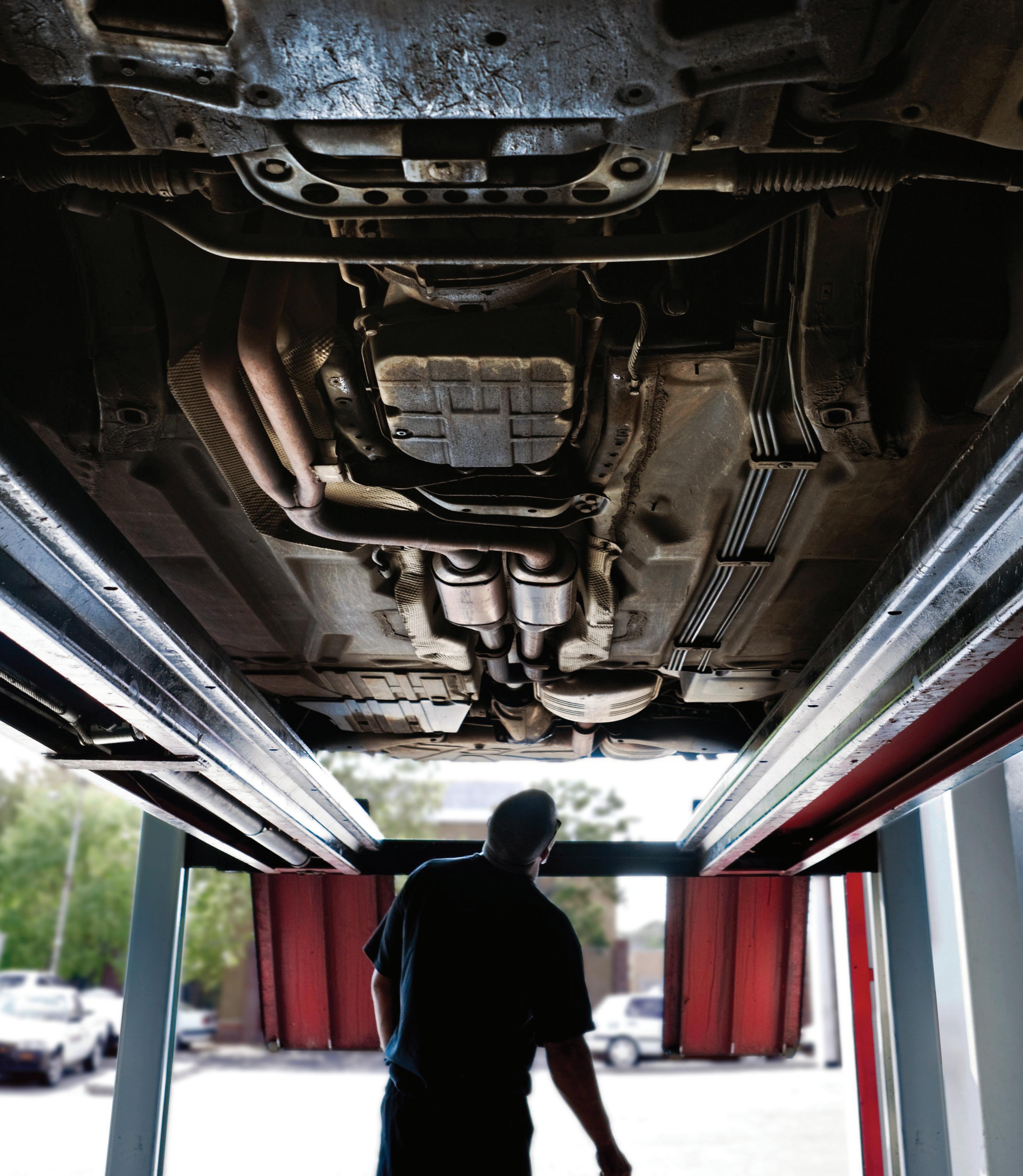
THE SUBJECT OF SHOP SAFETY covers quite a bit of ground, including personal safety and avoiding injury on the job, prevention of vehicle damage, proper use of lifts, shop ventilation, and more. Here we’ll discuss a number of these concerns.
Watch Your Back
Technicians are often subject to potential
back and joint injury due to lifting heavy objects or pulling wrenches from positions that make the back vulnerable to injury. Whenever possible, try to avoid working while bent over or reaching overhead. That’s easy to say but often difficult to avoid. During underhood service, work as much as possible at workbench height. When working over the fenders, consider raising the car to a comfortable work height to avoid back strain.
While we’re not interested in footwear fashion, it’s important to wear comfortable
shoes. In addition to footwear that offers toe protection and traction, shoes or boots should provide decent arch support and a cushioned liner. Standing for hours on end can take a toll on arches, and potentially transmit strain to leg muscles and the lower back. Also, avoid shoes or boots that are a bit too short, which will easily cause annoying discomfort and cramping of the toes.
Avoid Showing Off
Granted, especially among younger technicians, it’s often tempting to “show off”
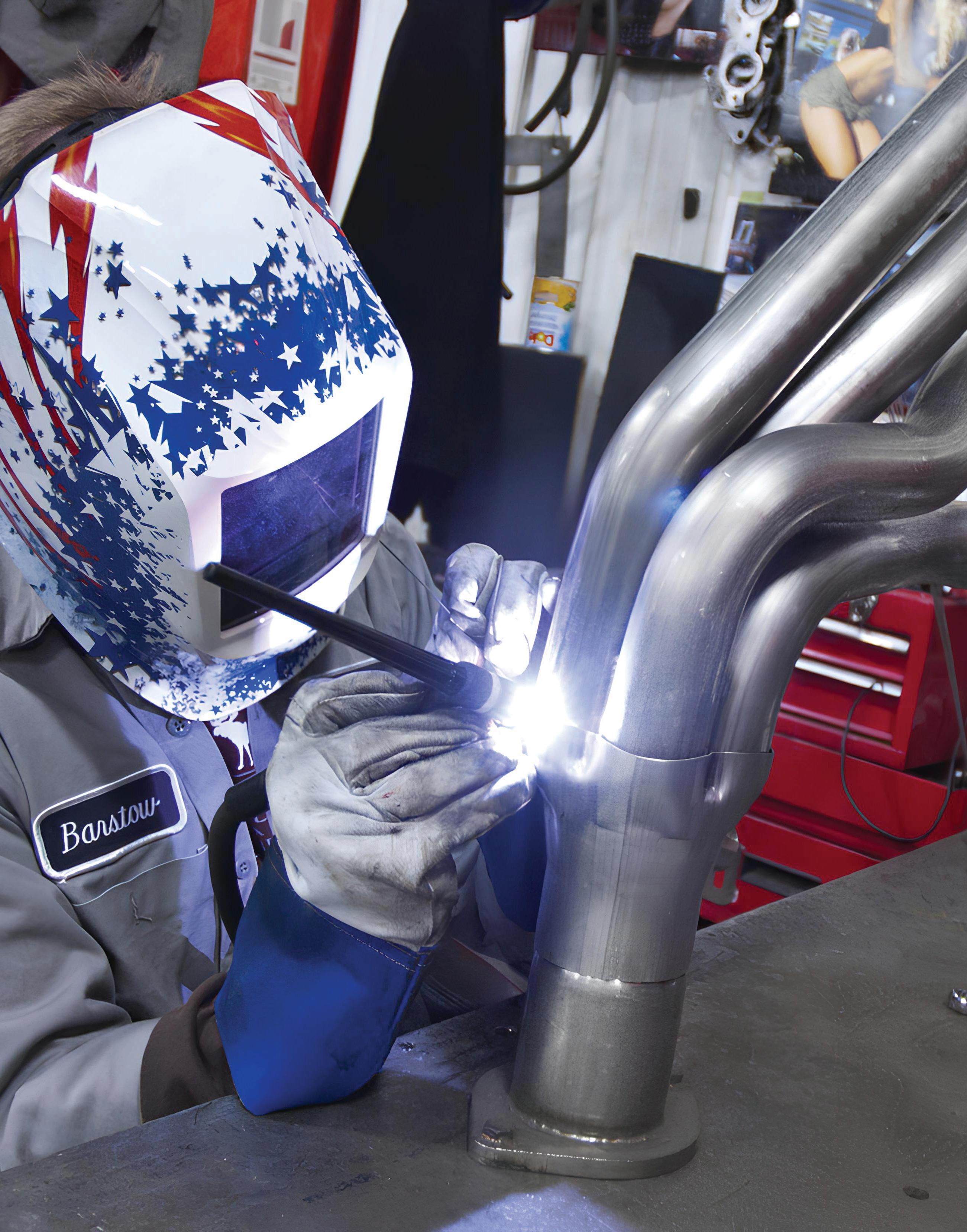
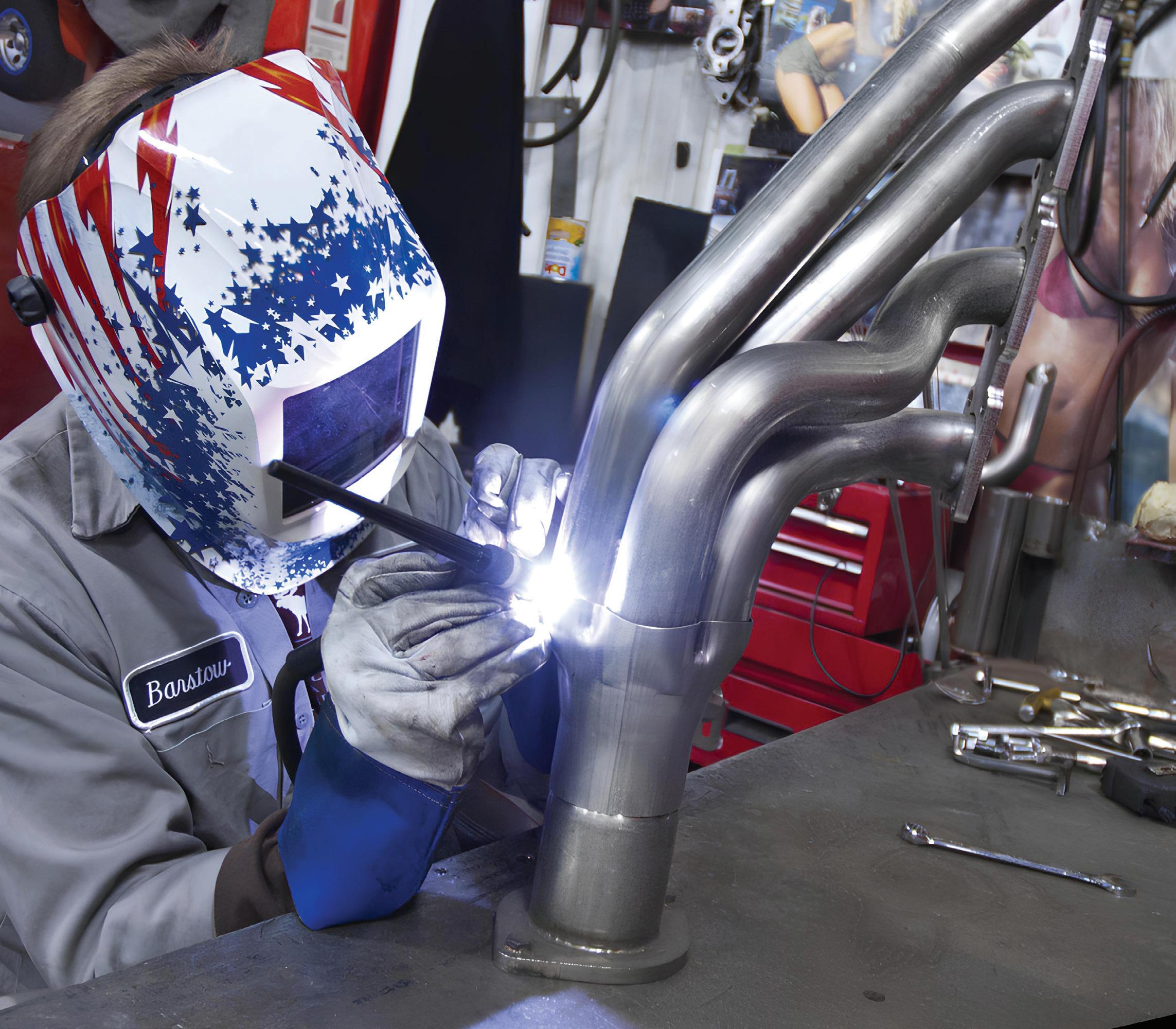
WHEN WELDING, wear an approved welding helmet with auto- darkening lens, welding gloves and shirt sleeves fully extended.
by lifting heavy objects. (Granted, many of us have been guilty of this.) Demonstrating your power and dedication may seem like fun at the moment, but routinely “going the extra mile” can take its toll on your knees, hips, and lower back. Whenever possible, try to enlist the help of coworkers when handling anything heavy. What is considered “heavy” varies not only with individual size and strength, but also with the position the technician is working in. There’s no shame in asking for help — getting the job done safely without injuring yourself is more important. While straining your back and legs unnecessarily may seem like a good idea at the moment, this can, and will be unhealthy in the long term.
Lift heavy objects from the floor using your legs. Do this by bending low at the knees with the back kept straight. If you think that the object exceeds 75 pounds, get help from a co-worker.
If back pain is already a reality (and to avoid this from the get-go), stretching and strengthening exercises both relieve pain and decrease vulnerability to injury. Admittedly, not everyone enjoys working out at a gym. Regardless, in order to perform your duties while avoiding joint and muscle damage, you can do yourself a tremendous favor by routinely limbering up by stretching hamstrings and back muscles, etc. This is nothing to take lightly. While it may be tempting, especially for younger workers, to display their abilities by lifting heavy objects to impress co-workers with their strength and resilience, it’s not worth the risk. In the long term, you’ll pay dearly for this. Just ask any tech who has amassed more than 10 years on the job.
Accidents During Installation
Accidents frequently result from failure to observe basic procedures. This is especially true for underhood fires. For example, when planning to remove an engine, begin by disconnecting the battery cable to ground and plugging any disconnected fuel lines and hydraulic
lines. These steps prevent fuel leakage and limit sources of ignition. Even without fuel leaks, something as simple as crossed ignition wires can start a fire in the manifold that can readily engulf the engine compartment. Always plan for the best and prepare for the worst. Establish a routine that forces you to think ahead and prepare for the worst case scenario.
Everyone in the shop building (not just techs) must be able to handle a fire extinguisher. That means knowing where each extinguisher is located and how to use them. It’s a good idea to conduct a workshop for all employees (perhaps once each year) in fire suppression. You can ask your local fire department to conduct such a class, either at your location or at the fire station. This allows everyone to gain hands-on experience in using an extinguisher. Being faced with even a “small” fire event without at least rudimentary training can easily result in a major fire. Don’t just point out where the extinguishers are located. Make sure that everyone actually knows how — and when — to use them. Naturally, in the event of a fire that you can’t immediately address, you’ll need to call the fire department, but having the knowledge to put out a small fire can spell the difference between a small amount of damage and a major blaze that can result in significant damage and injuries or even loss of life.
Remote starter switches also can lead to accidents because they bypass transmission neutral safety switches. Unless the transmission is in neutral or park, engines can start in gear and drive the vehicle forward. Place the transmission in neutral or park and set the parking brake before connecting a remote starter switch.
It is common to install engines after storing the vehicle for two weeks or more. During this time, the battery often discharges and is not recharged until installation of the rebuilt engine. The technician is sometimes in a hurry at this point and then recharges the battery at
the maximum charging rate. The problem with this practice is that batteries produce flammable hydrogen gas during heavy charging. Given any source of ignition, such as arcing at a loose battery cable or other electrical connection, the hydrogen gas ignites and blows the battery apart. Avoid this hazard by trickle charging the battery two or three days ahead of time. Of course, check for loose battery cables and other electrical connections before attempting to crank the engine.
Respiratory Hazards in the Shop
Too many technicians take hazards in their work environment for granted. They routinely work around gasoline and use cleaning solvent or other special purpose chemicals, and even when such products
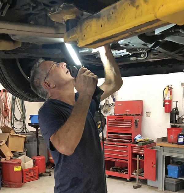
WHEN STANDING and working under a vehicle, try to avoid awkward positions where your back is bent. Granted, this is not always avoidable, but working at an awkward angle can lead to back strain. Try to reduce overhead work when possible.
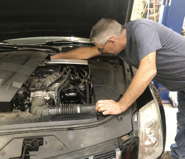
BENDING OVER an engine bay and reaching can lead to lower back issues. While not always practical, try to reduce work performed while bent over.
are known to affect health, they do not think of them as really “dangerous.”
Avoid inhaling any of these products. While this seems obvious, how often do technicians use compressed air to dry solvent or chemicals from parts? How often do technicians and machinists handle worn flywheels and clutches or brake parts contaminated with friction material particles? We must consider the long range, and sometimes unknown, consequences of working around chemicals, petroleum products, and friction materials and exercise greater caution.
Begin by checking the “MSDS,” or Material Safety Data Sheet, for each product used in the shop. Second, find alternative products to replace chemicals that are

particularly hazardous. For example, avoid cleaning products containing chlorinated hydrocarbons under any circumstances. Chlorinated hydrocarbons are carcinogens and accumulate in your system over time. Many technicians are unaware of potential hazards and accept unknown risks to their health by continuing to use them. Other steps required to reduce exposure are especially difficult because they involve changing work habits. For example, when using compressed air to dry parts, chemicals become airborne and subject everyone in the immediate area to respiratory hazards. Given allowable time, consider allowing parts to drain and blow passages clear later. Also consider using hot water as a rinse.
A few basic practices reduce respiratory risks. First, always work in well-ventilated areas or outside if the quantity of vapor is too great for interior ventilation systems to handle. Second, wear face masks appropriate for either vapor or particulate hazards. Particulate hazards include dust generated by bead blasting, blowing dirty or rinsed parts with compressed air, and grinding dust from clutch or brake parts brought into the shop for machining, etc. Whenever airborne particles are involved, always
wear eye, mouth, and nose protection — a respirator or disposable face mask.
General Safety Guidelines
Each piece of equipment has safety guidelines prepared for operators. Become familiar with these guidelines. Listed below are general safety rules that apply in any shop environment:
• Keep floors clean to prevent slipping on fluids or tripping over tools, parts, or air hoses.
• Wear safety glasses continuously while on the job. It is not always possible to anticipate when hazards will arise. It’s better to wear them and not need them instead of needing them and not wearing them. You’re only issued one pair of eyeballs. It only takes one mishap to result in a life-changing tragedy.
• Everyone in the shop must know the location of fire extinguishers and how to use them. This includes not only technicians but everyone, including office personnel and maintenance staff. Be diligent in making sure that all extinguishers are certified and ready for use. Take advantage of an outside fire extinguisher service company to regularly inspect and re-charge all extinguishers on a set schedule.
• Always connect exhaust pipes from running engines to outside ventilation when working inside.
• Hold a shop towel over work or holes to capture material blown loose with compressed air. Keep in mind that chips and dirt are directed across the shop unless precautions are taken. (This is yet another reason to always wear eye protection.)
• Do not siphon fuel. Drain tanks by transferring (pumping) fuel into another tank or approved gas can. Add fuel only from approved gas cans.
• Check all fuel lines and electrical connections before cranking engines.
• Meeting work deadlines is important, but regardless of how busy the shop may be on any given day, never run on
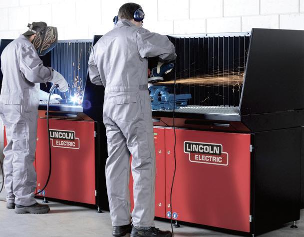
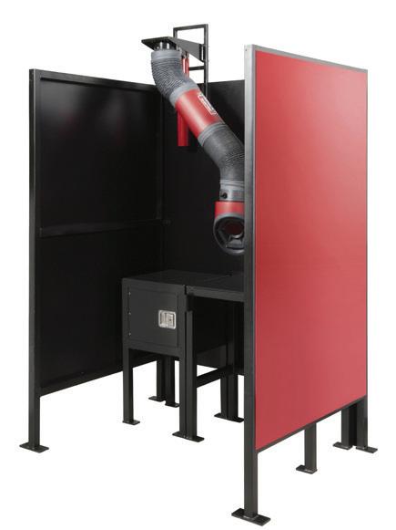
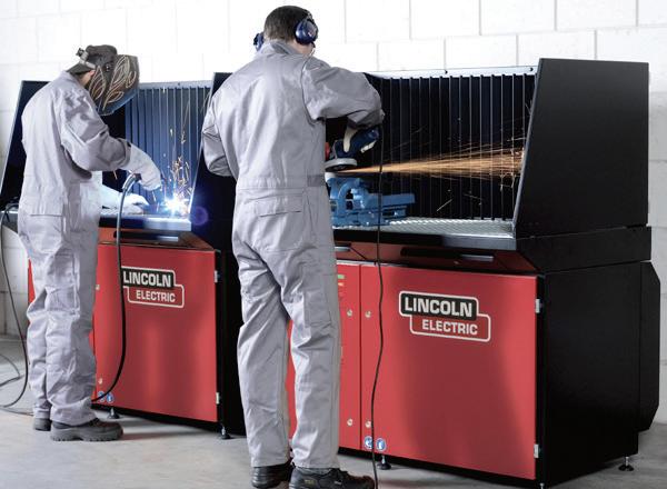
PROTECTING OTHER shop personnel is important when performing welding tasks. To protect other shop members from staring at welding flash, as well as keeping any fumes isolated, this example of a welding booth features walls to contain welding light and a vacuum to extract fumes, protecting the welder.
PHOTO BY LINCOLN
EXAMPLE OF auto-darkening welding helmet and heavy leather welding gloves with extended gauntlets.
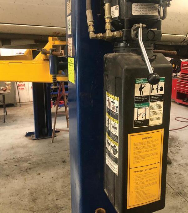
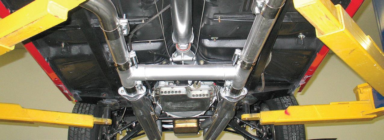
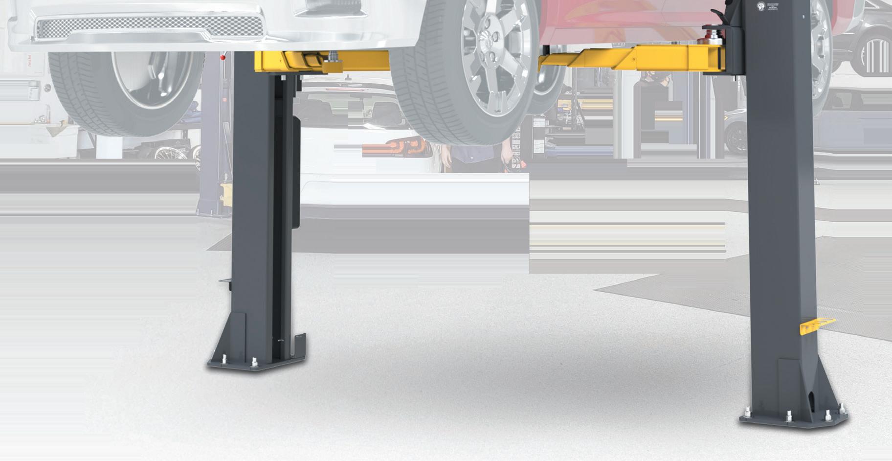
WHENEVER RAISING a vehicle on a lift, raise to working height, then carefully use the lift control lowering lever to lower the lift arms until the arms rest on the lift’s locking blocks before anyone stands under the vehicle. Never rely only on the lift’s hydraulics.
shop floors. The possibility of a fall, and injury, is high.
• Always leave keys in the ignition of vehicles when parked inside the shop. This enables moving cars quickly in the event of an emergency.
• Whenever handling a battery, always wear gloves and eye protection. Wash yourself and your clothing immediately in clear water should you spill or come in contact with battery acid.
• Switch battery chargers off and wear safety glasses before connecting or disconnecting charger cables. Because battery charging produces explosive hydrogen gas, trickle charging is preferred to fast charging.
• Keep clear of exhaust manifolds, fans, and belts or pulleys when working in the engine compartment. Watch especially for electric fans because they can start without warning. Whenever working on or near moving parts (for example, while an engine is running), be aware of anything — even items on your body — that could potentially get caught. Long hair and/or long beards should be tied/ tucked away. If long sleeve shirts are worn, the cuffs should be buttoned, or shirt sleeves rolled up. Avoid wearing rings, watches, or bracelets.
• Wear goggles and gloves for protection when welding or using an oxy-acetylene torch, arc, MIG or TIG welder. Remember that electric welding exposes others in the area to arc welding flash and that they may not be aware that work pieces are still hot. Set up safety screens and warn co-workers that the flash can burn eyes. Write “hot” on welded parts with soapstone or chalk. Always wear welding gloves, gas welding goggles, a welding helmet and a screen to protect others from welding flash.
• Flush skin and clothing with water if exposed to chemicals or fluids. If eyes are exposed to any contaminants, refrain from rubbing the eyes and flush with water for 15 minutes and have them checked by a doctor or nurse.
Again, always wear eye protection to avoid or at least minimize the chances of eyesight injury.
• Wear only work shoes with oil-resistant soles and safety toes. If the soles of the shoes/boots become contaminated with any slippery substance, stop what you’re doing. Remove the footwear and clean/ dry the soles before continuing.
• Slippery shop floors are a real hazard. Always remove and clean any floor areas of any spilled fluids, and make sure that the floor dries completely. Floor fans can aid in drying floors that have been mopped. Place yellow or orange safety markers around any wet floor area while drying.
• Check that hood supports are secure before going to work in the engine compartment. If in doubt, prop open the hood with a rod or on major jobs, remove the hood entirely.
• Immediately report even minor injuries so they may be checked and treated if necessary.
• Close drawers after removing tools from tool chests so that others do not catch themselves on open drawers as they pass by. To prevent sudden weight shifts and tipped over tool chests, close and lock drawers before rolling them around the shop.
Lift Safety
• Only choose a lift that features the ALI (Automotive Lift Institute) label. This indicates that the lift meets design and construction requirements.
• Know the weight of the heaviest vehicle you plan to lift and choose a lift that meets that maximum capacity.
• Before operating a lift, pay attention to your surroundings. Check the area to confirm that there are no obstructions. Lift the vehicle no more than 12 inches from the ground and pause to again check the surrounding area. Confirm the vehicle is level as it is being lifted and check for doors that may be open.
• If using a mobile column lift, always place the lift on a firm and level surface. If using the lift outdoors, be aware of wind loads.
• All lifts should be inspected and serviced according to the liftmaker’s recommendation for scheduled maintenance. Ignoring scheduled inspections can lead to disaster.
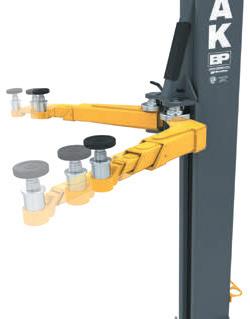
• Check for proper lift points before jacking up a car or raising it on a hoist. When using a twin-post lift, make sure to use only the factory recommended lifting points. Lifting at soft areas such as the floor pans can severely dent the pans and can cause major damage. Using improper lift points can cause vehicle imbalance, which can result in the very real potential for the vehicle to slip and fall from
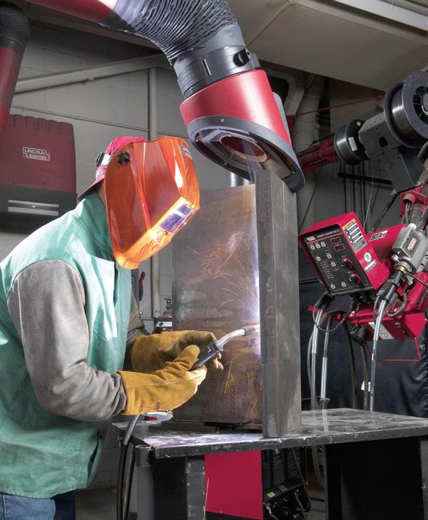
WELDING FUMES can be safely removed from the work area with a fumes vacuum system.
PHOTO BY LINCOLN
WHEN WELDING or grinding, protective apparel and safety shields protect the operator and others nearby. This downdraft booth system is an example. PHOTO BY LINCOLN


the lift. If the vehicle owner is concerned with appearance (luxury car, restored vehicle, classic car, etc.), it’s a good idea to place clean rubber pads or shop towels between the lift pads and the vehicle to prevent marring. Never lift a vehicle immediately after placing the lift arms in position. Raise the vehicle to bring the tires just off the shop floor, then “rock” the vehicle by hand at the front and rear to confirm the vehicle is stable and not imbalanced. Once the vehicle is raised to the required height, use the lift’s control to gently lower the lift arms to its resting locking blocks. Never solely depend on the lift’s hydraulics. When using a floor jack, place safety stands under the car before continuing. Whether dealing with a lift or a floor jack, never depend on the hydraulics alone.
Benefits of Cordless Tools
Whenever practical, consider the use of cordless power tools. This eliminates the need to drag compressed air hoses around the shop floor, and reduces the risk of someone tripping over the hose. Today’s cordless power tools offer substantial torque and long-life rechargeable batteries.
Handling Hazardous Materials
Over the years, technicians have generally taken the variety of chemicals and chemical byproducts in their workplace for granted. While it is easy to view efforts
at controlling these materials simply as regulatory meddling, our personal health and our environment are at stake.
Hazardous materials are defined in regulations as ignitable, reactive, corrosive, or toxic. While specific parameters for each of these characteristics are detailed in the Resource Conservation and Recovery Act (RCRA), defining characteristics include the following:
• Ignitable materials have a flash point below 140 degrees Fahrenheit or ignite spontaneously or by friction.
• Corrosive materials have a pH below 2.5 or above 12.5 and corrode steel at a rate of 0.250 in or more per year at a temperature of 128 degrees Fahrenheit.
• Reactive materials are unstable, change violently, and may form explosive mixtures or generate toxic fumes.
• Toxic materials are poison if ingested or inhaled or are carcinogenic.
Information describing contents, hazards, and first aid is included in Safety Data Sheets (previously known as Material Safety Data Sheets or MSDSs). All vendors are required to make available SDSs for the products they sell. Under “Right to Know” requirements included in regulations, shops must maintain a file of SDSs for employee reference. If uncertain of product contents, or if considering new products, check the information contained in the SDSs.
Workstations
• Change fluids or perform cooling systems services and repairs only indoors. Working outdoors increases the possibility of fluids getting into storm drains or ground water.
• Take all necessary precautions to capture fluids and wipe up spills prior to mopping floors. Since mop water is disposed of in sewers, using mops to clean up excessive quantities of oil adds to wastewater treatment problems. Use absorbents and then wipe with shop towels prior to mopping.
• Drain and recycle all fluids from engine


ALWAYS WEAR eye protection during any aspect of shop work. Keep a supply of clear safety glasses and get into the habit of wearing them.
AN EMERGENCY eyewash station allows an immediate initial rinsing of eyes that have been exposed to chemicals or debris particles.
AN EMERGENCY shower station provides immediate personnel rinsing in the event of harmful contamination. Granted, not all shops may have the ability to add this, but consider installing one if at all possible.
WHEN DEALING with luxury/ high-priced vehicles and classic/restored vehicles, always use clean rubber cushions and/or clean rags between the lift pads and the chassis to prevent nicking/dings/scratches. On a twin-post lift, once the lift arm pads contact the vehicle, raise the vehicle slightly, with tires just off of the floor, and apply down/up movement at the front and rear to verify solid contact and balance. Never raise a vehicle on a twin-post lift without first verifying balance.


and transmission cores before shipping or storage. This reduces the potential for spilled oil getting into storm drains or ground water.
• Dump mop water only into drains directed to sewers.
Shop Towels
• Use absorbent cotton shop towels. Once used, disposable towels become hazardous waste.
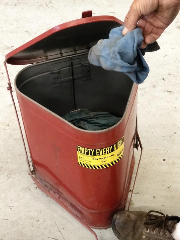
• Store cotton shop towels in fireproof metal cans after use. While working, technicians can collect used towels in a plastic bag in their toolboxes.
• Launder cotton shop towels through a commercial laundry service. They are equipped to properly handle water discharges after washing.
Oils, Fluids, and Coolants
• Drain engine oils and transmission fluids into double containment units. Cover the primary container when not in use and keep the secondary side clean.
• Capture coolant and store in a separate double containment unit.
• Recycle oils and coolants to conserve resources and to avoid hazardous waste disposal handling charges.
• In case of a spill, use absorbents and/ or wipe with shop towels before mopping. For small spills, wiping with shop towels is preferred since used absorbent materials require handling as hazardous waste.
• Report spills of more than one pound (estimated) to management. Regulatory agencies generally require that management keep a log of such spills.
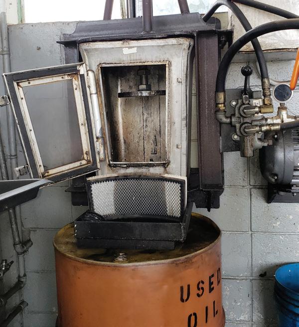
Oil Filters
• Drain used filters thoroughly by puncturing the case and placing them upright in a bucket or barrel. Crushing them is even better since more can be
collected per barrel, thereby reducing the cost of hauling.
• Collect drained or crushed filters in a closed top barrel and store in a dry place. These materials are recyclable.
Solvent
• Work only in approved solvent cleaning stations that meet requirements for vapor control and fire safety. This typically means a limited sized opening over the reservoir and a lid equipped with a fusible link that drops over the tank in case of fire.
• Report spills of more than one pound (estimated) to management, as a log of such spills is generally required.
Friction Materials
• While asbestos is no longer used in the making of friction materials, if you happen to work on an old (vintage) vehicle, use caution, as it is possible that original-type friction materials including clutches and brakes may contain asbestos. Even where asbestos friction material is not present, always wear face/breathing protection, as any contaminants can be harmful to ingest.
• Wash all flywheels, clutches, and brake drums or rotors before machining them and wash hands after handling. This reduces the possibility of inhaling or ingesting contaminants.
• Place all used clutches and other friction materials in a closed barrel and store in a dry place. These materials are recyclable or can often be returned to rebuilders as cores.
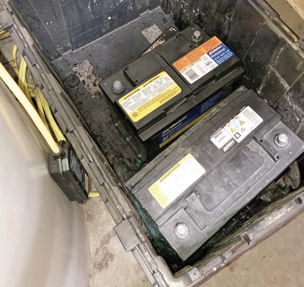
Batteries
• To reduce handling, charge batteries while still in the vehicle if possible.
• If removed from the vehicle, place them in a plastic secondary container (non-metallic) to protect against spills containing acid and lead.
• Store battery cores separate from other materials in a secondary containment unit. Battery cores are recyclable.
STORE OILY/CONTAMINATED shop rags in an approved fireproof can. A foot pedal is depressed to open the lid. This provides safe temporary storage of used rags. Oil or fuel contaminated rags present a fire hazard if left in the open.
ALWAYS STORE used batteries in a plastic container, avoiding metal containers that can result in a spark if terminals were to contact the container.
EXAMPLE OF an oil filter crusher. The used engine oil filter is placed in the unit and a hydraulic ram extends downward and crushes the filter. In this example, the oil that is squeezed out runs through an air filter before being drained into the used oil barrel.
PHOTO: DWAYNE DUGAS
The Fastest Way To Order Parts
Parts & Tires In One Click
In 2025 we’ve added over 30+ tire suppliers to Nexpart Multi-Seller for FREE. Find aftermarket parts & tires fast with one-click ordering. See live inventory and your wholesale price from ALL of your trusted local suppliers on ONE screen.
Suspension Innovations & Alignment Essentials

The evolution of modern suspension and steering: innovations, challenges, and alignment basics
BY JEFF TAYLOR
TODAY’S STEERING SYSTEMS are designed to maintain the correct wheel alignment for optimal tire-to-road contact while minimizing tire wear and still being able to adapt to variable road conditions for improved handling and stability. But the steering system hasn’t been the only concern of the automotive manufacturers. There has been a proliferation of active suspension systems, integrated with sophisticated sensors and electronic controls that adjust in real time and provide an unprecedented level of comfort and control while driving.
Active or Adaptive Suspension Controls: the Differences
Suspension systems have evolved signifi-
cantly beyond their traditional role of simply providing a smooth, comfortable ride. Modern innovations now integrate adaptive and active controls, allowing vehicles to respond dynamically to changing road conditions and driving demands. These systems not only focus on comfort but also enhance handling, reduce body roll, and maintain optimal ride quality. Some manufacturers are incorporating adaptive or active suspension variants, or a combination of both on their vehicles — all to improve overall vehicle performance and stability.
The key difference between adaptive and active suspension systems lies in how they adjust to road conditions. Adaptive suspensions adjust the ride height in response to real-time road feedback or
driver input, while active suspensions use electronic controls to manage vehicle height and proactively control body roll and stability. To address the limitations of a one-size-fits-all approach, many manufacturers combine both systems, offering enhanced adaptability and performance across a wider range of driving scenarios. Active suspensions will often use bi-state, tri-state, continuous, or magneto-rheological damping control in the struts or shocks to control ride quality and body roll (but for this article we will concentrate on the adaptive suspension system).
The adaptive suspension system is used primarily to control the vehicle ride height, but it can be used to control stability as well. The most common adaptive sus-
pension version uses air springs to keep and control ride height. But there are hydraulic versions: Mercedes Benz S-Class and the BMW 7 series use a hydraulic adaptive/active suspension. This system controls ride height, damping force and body roll, hydraulicly. But these systems are relatively rare.
The air ride adaptive suspension is the more common version, and its name will depend on the marketing of the system by the manufacturer. Ram calls their system “Active-Level Four Corner Air Suspension.” GM calls their system “Air Ride Adaptive Suspension.” Ford has the “Adaptive Air Suspension” and Tesla has the “Smart Air Suspension.” Input information from vertical and lateral accelerometers, suspension position sensors, air pressure sensors, steering position and other pieces of data are sent either directly or via a network to the suspension controller for proper operation. The controller will then send out the needed commands to either the air spring control valve assembly or air spring to satisfy the required or requested driving conditions.
Adaptive Suspension Issues and Concerns
Compressor failures, air spring failures, airline leaks, and corrosion are the most common issues. Warning lights, DTCs and sagging tilted vehicles are a common issue. A good thorough visual inspection and a full system scan will often point to the issue when dealing with these systems. When looking at a failed Ram air ride system there are four common failures that we look at first: the 40-amp compressor fuse being blown, the compressor relay, a seized compressor and soapy water looking for air leaks. Another common Ram or Jeep air suspension issue is that the vehicles will revert to “plant mode” and disable the filling of the air bags. When this happens the vehicle will stay low and have a C2212:00 DTC set in the Air Suspension Control Module (ASCM) that can’t be cleared. The common fix for this condition, after all the
proper repairs are completed, is to use the scan tool and follow the filling from reservoir procedure. Typically, you only have to fill one corner, and this should take it out of plant mode and raise the vehicle to the correct height when the engine is started. Ensure all the doors and the tailgate are closed when doing this procedure. Another Ram tip is resetting the system. This is done with the ignition on, engine off. You will then press and hold the air suspension button for 40 seconds, and the system should recalibrate itself.
When working on or servicing the suspension on these systems, following the OEM service procedure is imperative, as many of these systems will hold residual pressure and that pressure may need to be relieved before service to prevent injury or damage. Both GM and Ram have special procedures to reset or learn the automatic level trim heights. Newer GM SUVs equipped with the automatic level control have a 13-step procedure to reset the learned trim height after a suspension position sensor is replaced or removed. It involves careful measurements in millimeters and that value will have to be entered into the scan tool as part of the procedure.
And once any repairs have been performed on the system, it may need to be refilled with nitrogen. This is a part of the
air ride service that often gets missed, but the system needs to be filled with nitrogen to prevent any internal corrosion that compressed shop air may contain. Again, following the OEM service procedures can’t be stressed enough.
When performing an alignment on these air-ride-equipped vehicles, technicians need to pay attention to the settings of the suspension system. The evolution of suspension technology has also led to the development of unique alignment procedures tailored to specific vehicle designs. GM and Ram have an Alignment Mode, Tesla uses Jack Mode, which must be entered into before doing an alignment. Alignment mode can be entered into using the dash or center information stack or the scan tool, and once entered the vehicle’s
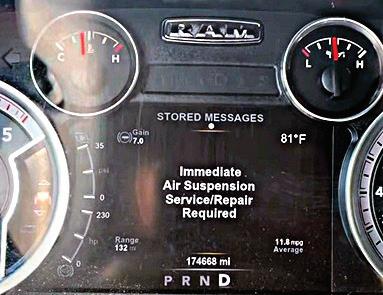
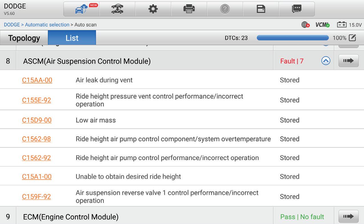
UPON INSTALLING the scanner on the Ram and performing a diagnostic scan, numerous Diagnostic Trouble Codes (DTCs) related to the adaptive air suspension system were identified.
THIS WARNING on the dash of a 2016 Ram is alerting the customer to an issue with the Active-Level Four Corner Air Suspension system on the truck. ALL PHOTOS BY AUTHOR

suspension system will move the vehicle to the correct position. This will optimize the vehicle’s height to provide the most accurate wheel alignment, and this mode should be enabled once the vehicle is driven onto the alignment rack. Manufacturers like Toyota and Ford emphasize post-alignment recalibrations to ensure their Advanced Driver-Assistance Systems (ADAS) components function seamlessly.
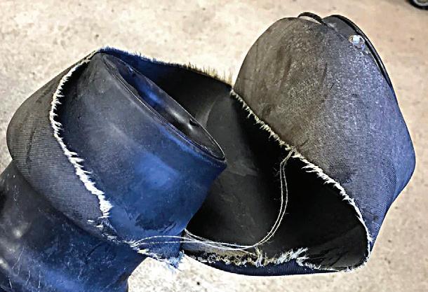
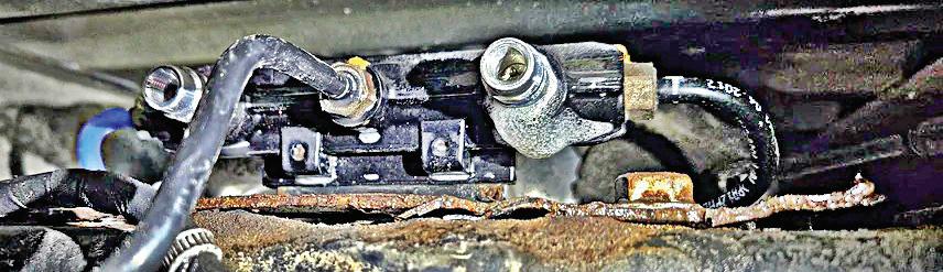
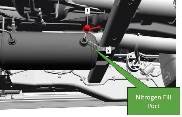
The Modern Steering System
With all the technological changes that we technicians see on today’s vehicles, the three fundamental steering angles (camber, caster, and toe) and the steering geometry angles (steering inclination angle, scrub radius, included angle, and thrust angle) are important to understand. These steering settings and angles, some of which are adjustable and some of which are not, are vital to proper vehicle steering, safety, and driveability.
Examining the Adjustable Angles
Camber is the tilt of the wheel when viewed from the front or rear. It can be either positive (tilted out at the top) or negative (tilted in at the top). The camber setting optimizes tire contact with the road for various driving conditions. Negative camber enhances cornering grip by maintaining the tire’s contact patch during turns. However, too much negative camber can lead to uneven tire wear and instability on straight roads. Positive camber has the top of the wheels tilting outward. Positive camber is uncommon on today’s vehicles and may result in poor cornering stability and uneven tire wear.
Caster is the tilt of the steering axis as seen from the side of a vehicle. Positive caster means that the top of the steering axis tilts toward the driver (rearward), whereas negative caster tilts it away (ahead). Positive caster is widely used because it improves straight-line stability, steering feel, steering self-centering, and better cornering performance. Negative caster reduces steering effort, but it sacrifices stability and can lead to wandering, poor cornering, and reduced vehicle control. While caster does not directly impact tire wear, excessive positive or negative caster can indirectly contribute to tire wear by causing misalignment in other suspension components or uneven weight distribution during turns.
Toe refers to the angle at which the tires point in relation to each other when viewed from above. Toe-in occurs when the
TORN OR leaking air springs are a common issue on the adaptive air ride system.
THIS LEAKING fill valve assembly was found to be part of the problem on the Ram. Using a soapy water mixture showed the leak, due to corrosion.
WHEN REFILLING the adaptive air-ride system it is imperative to use nitrogen in the system to prevent moisture from causing corrosion internally to the system.
THIS BENT outer tie rod was easily found during a visual inspection, but bent control arms, struts or other components are not always as easy to find.
front edges of the tires point inward, while toe-out occurs when they point outward. Proper toe settings ensure that the vehicle handles properly and maintains stability. A toe-in setting is often used on vehicles to counteract the natural tendency of the tires to spread outward under acceleration, especially in front-wheel-drive vehicles. A toe-out setting on the other hand, is sometimes utilized on high-performance vehicles to enhance cornering response. Improper toe settings can significantly impact tire wear and often make the vehicle feel unstable or uneasy, which affects both straight-line tracking and cornering performance.
Nonadjustable But Critically Important Angles and Measurements
Steering Axis Inclination (SAI) is the angle formed between the steering axis and a vertical line when viewed from the front or rear of the vehicle. This angle is built into a suspension design and cannot be adjusted. SAI helps return the wheels to a straightahead position after turning, improving stability and steering control. Scrub radius, on the other hand, is the distance between where the steering axis meets the ground and the tire’s centerline. Both SAI and scrub radius influence how the vehicle steers, handles, and how the tires wear.
The relationship between SAI and scrub radius is important because they work together to determine steering characteristics. For example, a positive scrub radius (when the tire centerline is inside the steering axis) can cause issues such as toe-in and instability or darting when braking. A negative scrub radius (when the tire centerline is outside the steering axis) can lead to toe-out and potential instability while driving.
Any changes or deviations in SAI or scrub radius may indicate suspension damage or a bent component, which often goes unnoticed to the naked eye during a visual inspection. SAI and scrub radius are critical for ensuring proper steering stability and tire wear, and provide
valuable diagnostic insights during an alignment to detect suspension damage or misaligned components.
The included angle is the sum of the SAI and camber angles, forming the angle between the tire’s centerline and the steering axis. It plays a critical role in vehicle alignment diagnostics, as deviations often signal issues like cradle misalignment or damaged suspension components. Alignment machines measure this angle, and it should be consistent between the left and right sides, typically within a half-inch (12.7mm). If the included angle difference exceeds 1.5 degrees, it shows potential suspension damage. These variations directly affect steering stability, tire wear, and overall driveability, and highlight how the included angle is an essential diagnostic tool for maintaining proper vehicle handling.
The last critical angle that we will look at is the thrust angle, but we will include setback as a measurement here as well. The thrust angle refers to the angle or difference between a vehicle’s geometric centerline and the direction in which the rear wheels are pointed. It plays a key role in ensuring the vehicle tracks straight and handles properly. A misaligned thrust angle can result from issues such as bent axles, damaged frames, shifted rear cradles, worn suspension components, or improper rear toe settings. Symptoms of an incorrect thrust angle include off-center steering, vehicle pulling, dog tracking (where the rear end appears offset), crab walking (moving slightly sideways like a crab), and uneven handling. Modern alignment equipment is used to measure and adjust the thrust angle, particularly in vehicles with adjustable rear suspensions. For non-adjustable suspensions, the front wheels can sometimes be aligned to compensate. A proper thrust angle is essential not only for stable handling and tire wear but also for maintaining the accuracy of ADAS, which relies on precise alignment with the vehicle’s travel direction.
A thrust angle reading under 0.25 degrees typically means nothing is bent
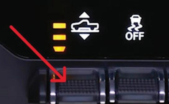

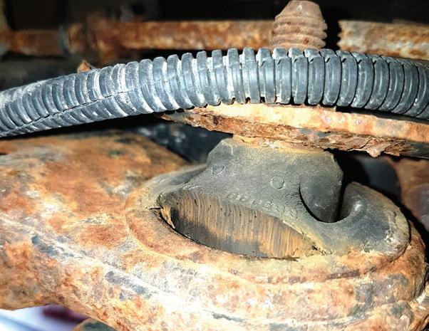

TO RESET the Ram or Jeep air ride system you can try holding down the air suspension button for 40 seconds. This should reset the system.
THIS PHOTO of the dash on a 2014 Jeep Cherokee shows the Wheel Alignment Mode softkey, to instruct the air suspension control module to put the vehicle’s suspension in the correct position for an alignment to take place.
MODERN ALIGNMENT racks precisely set angles and adjustments for proper alignment, and also identify bent or damaged parts and shifted cradles that might not be visible during a visual inspection.
WORN OR torn control arm bushings like this one can often cause issues with vehicle handling and possibly tire wear. These need to be checked and repaired before an alignment can be performed.
or damaged, while higher readings on a live rear axle (cradle type) can point to shifted frame mounting points. Setback is the distance (from the wheel center) that one front wheel is farther back from the other. This measurement can highlight frame or suspension damage, such as bent control arms or worn bushings. Misalignment in thrust angle and setback may signal frame damage, like a “diamond frame,” where one side rail has shifted and affected suspension mounting points. Alignment checks, especially after an accident, can be used for finding thrust angle issues, particularly in all-wheel-drive vehicles, with rear cradle suspensions. Typically, most thrust angle problems can be corrected with toe adjustments, but a shifted cradle might limit those adjustment possibilities.
The four-wheel alignment is the most accurate alignment procedure. This in-
cludes aligning the rear wheels to the vehicle’s geometric centerline and thrust line and then aligning the front wheels parallel to the rear wheels. The process ensures best handling, even tire wear, and proper tracking of the vehicle. Using a modern alignment machine, technicians can diagnose irregularities, identify damaged or shifted components and make changes thanks to the accurate measurements these machines provide.
As vehicles continue to evolve, so will suspension and steering systems, but the essential steering angles and settings are still there and as important as ever. Future advancements are likely to focus on even greater integration with vehicle control systems, improved energy efficiency, and enhanced durability. For now, the shift toward electronically controlled and adaptive suspension systems represents a significant leap forward, providing drivers with
unparalleled comfort, safety, and performance. Whether managing the complexities of ADAS integration or refining the ride quality of luxury vehicles, modern suspension systems stand as a testament to the power of innovation in automotive engineering.

JEFF TAYLOR is a seasoned professional at CARS Inc. in Oshawa with 40 years in the automotive industry. As a skilled technical writer and training developer, he holds licenses in both automotive and heavy-duty vehicle repair. Jeff excels in TAC support, technical training, troubleshooting, and shaping the future of automotive expertise.


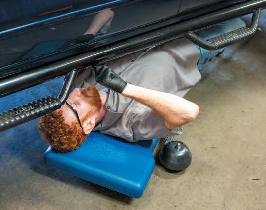

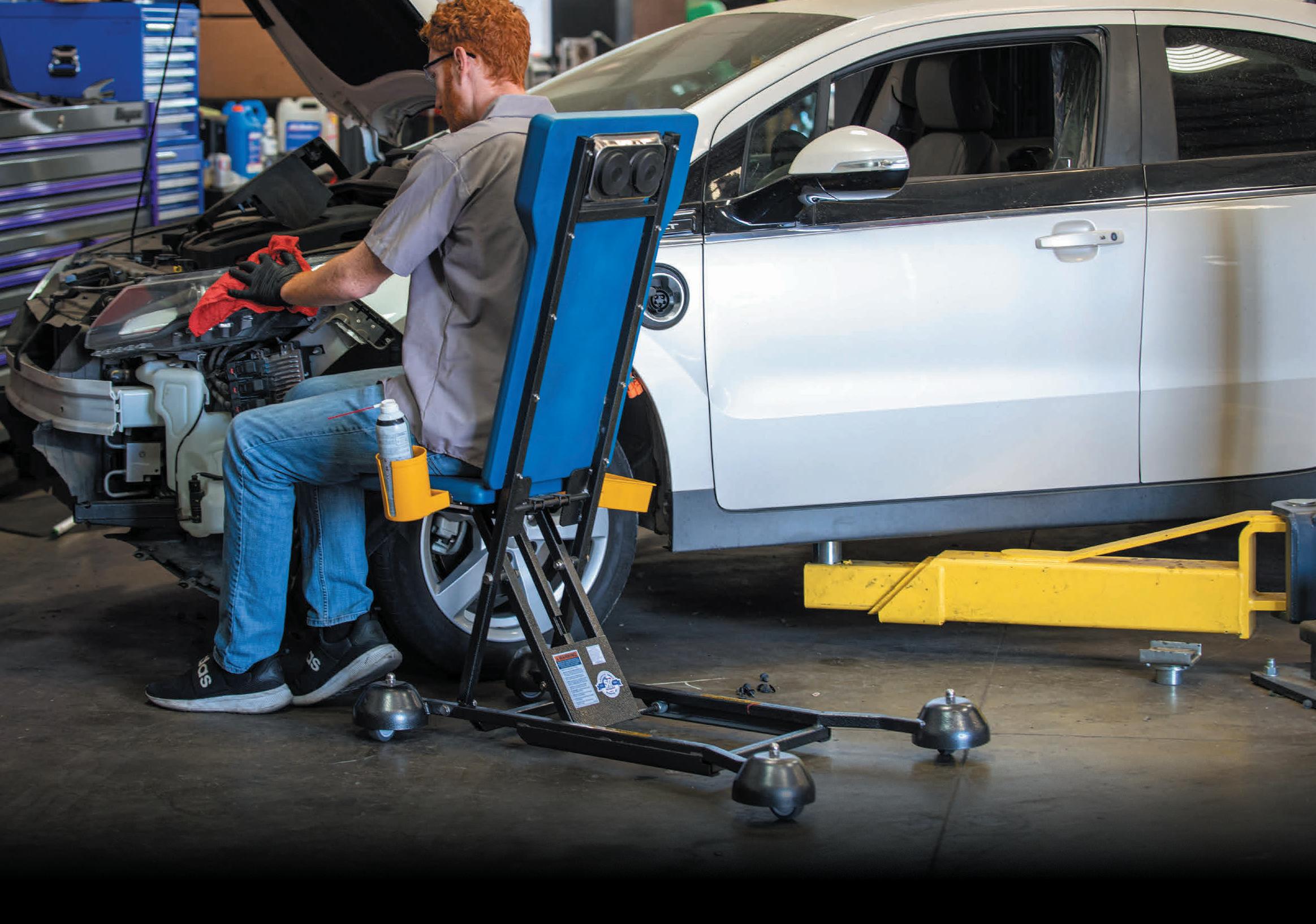


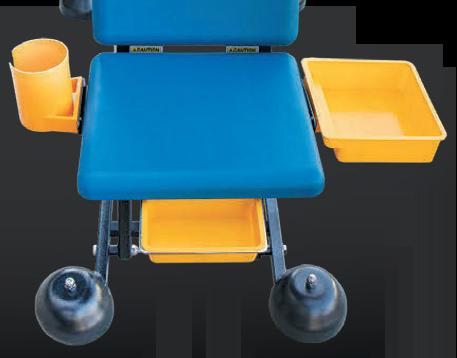

Lost in Translation
When life gives you lemons, make lemonade — not Lemon Law.
BY BRANDON STECKLER // Technical Editor
COMMUNICATION FAULTS are frequently among the most difficult to solve, but when the fault is both intermittent and instantaneous, we are now talking about a whole new level of challenge. And when the customer is so upset they wish to pursue a Lemon-Law claim, it’s time to step up to the plate — and be sure to bring your “A-Game!”
Today’s Subject Vehicle
A student reached out to me with a 2014 Jeep Cherokee as it entered his shop with the complaint of “loss of communication at times.” The diagnosis began with a scan for DTCs for each node on all the networks. Fault codes existed solely for communication faults. There were a total of 10 DTCs and all of them existed only on the CAN_C network (Figure 1).
After reviewing and documenting the stored DTCs, it seemed all pertained to complaints with either the CAN bus, in general, or three specific nodes:
• ABS control unit
• Transmission control unit
• Power Steering control unit
Searching for the Correct Diagnostic Path
The above information led to visiting the topology of the system configuration. This layout of the entire CAN_C bus (along with the stored DTCs) helped to triangulate a likely area where the fault may lie, and more importantly, suggested an area to begin testing the CAN_C bus circuitry (Figure 2).
Now, considering the bus will support communication of the other nodes, some assumptions can be safely made. The CAN_C bus cannot be shorted to ground, shorted to voltage, or CAN_HI / CAN_LO cannot be shorted to each other. What’s more is that all suspect nodes share the same Star Connector (a comblike splice pack). The Star Connectors also house the terminating resistors that stabilize the bus.
The most logical approach is to view
WELCOME BACK TO ANOTHER EDITION OF “THE DATA DOESNT LIE,” A REGULAR FEATURE, WHERE I POSE A PUZZLING CASE STUDY.

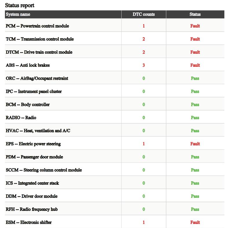

2 Stored DTCs and this CAN_C bus topography diagram work together and help to triangulate a suggested test location for the cause of the communication fault.
FIGURE
FIGURE 1 All communication faults should begin with a vehicle-wide all-DTC scan. Scan results like this offer the common node(s) that non-faulted nodes are complaining about.
TECH CORNER
FIGURE 3 (BELOW) Waveforms of both CAN_HI and CAN_LO were captured at the DLC and at the PCM. This strategy captured the waveforms on either side of the Body Star Connector. The difference between the pairs (RED/BLUE vs. GREEN/YELLOW) can be seen and confirms a circuit issue is present in the media carrying the messages.
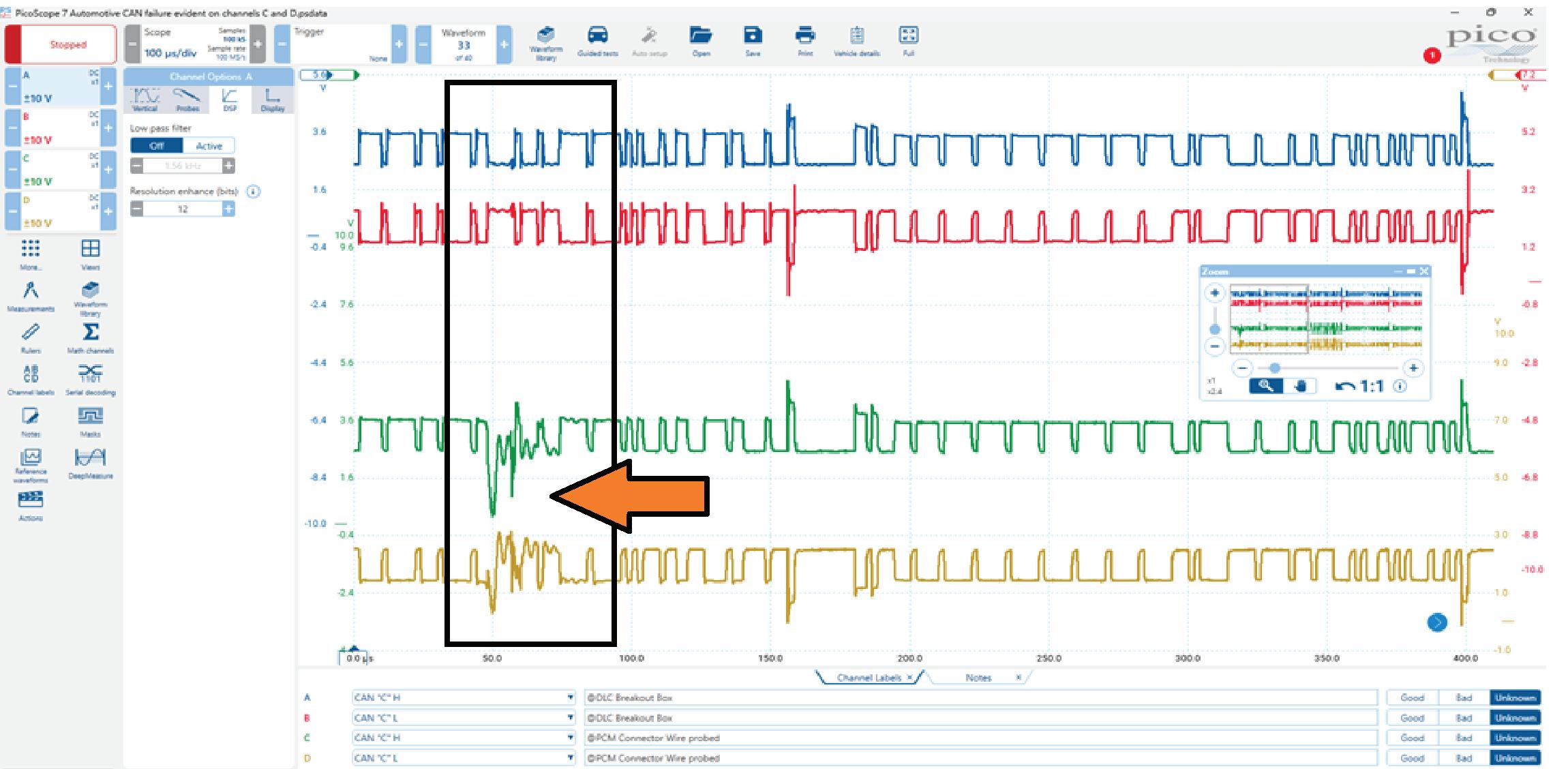
FIGURE 4 (BELOW) This waveform capture shows inductive kicks present each time a communication activity transitions from dominant-to-recessive, and from recessive-to-dominant. The very next message (not visible in the capture) appears normal. This could be a clue that we are witnessing a transceiver issue within a node.
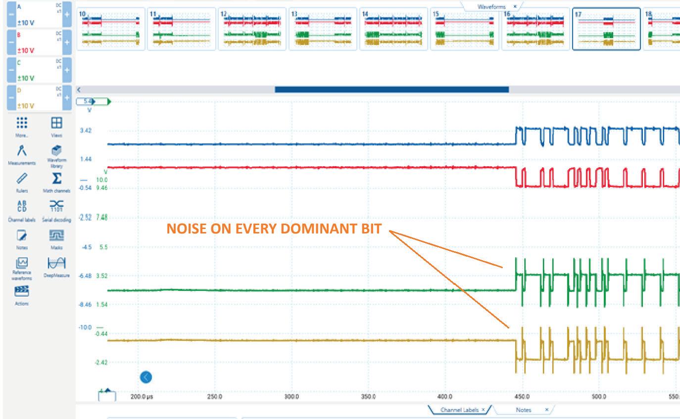
the CAN_C bus scope waveforms (live activity of the bus messages being exchanged). However, considering the nature of the fault, it’s best to capture in two different areas (at the DLC, terminals No. 6 and No. 14 and at a node downstream of the Body Star connector). The PCM was the chosen node (the inline-connector C1205, at the dash, just after the PCM, was the sample point). This is mainly due to relatively-easy access.
Assembling the Puzzle Pieces
When sampling at both locations, there is a distinct difference in the paired waveforms. RED and BLUE (CAN_HI and CAN_LO, respectively) were sampled at the DLC. GREEN and YELLOW were the same circuits but sampled at the PCM (passing through the Body Star Connector).
There is a visible fault present
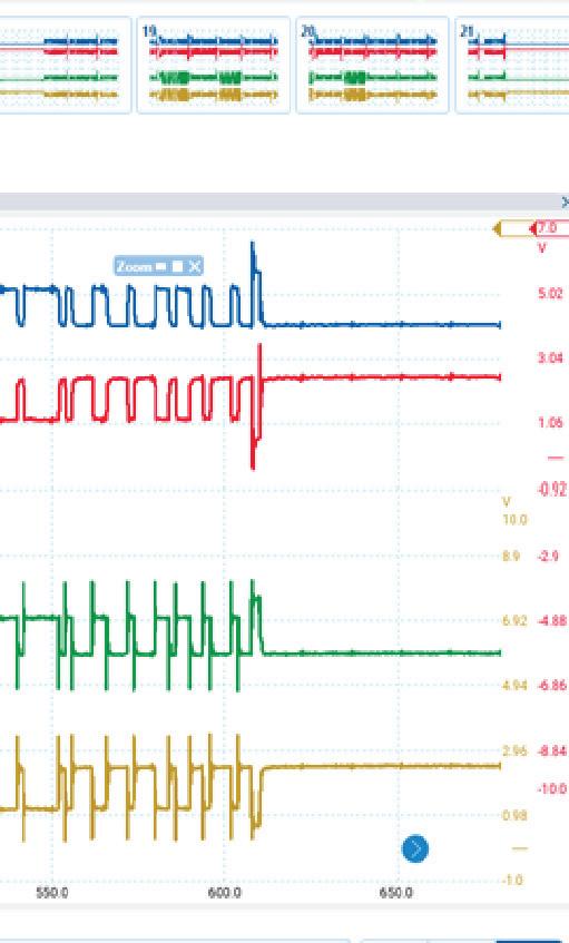
at the PCM sample point but not at the DLC (Figure 3). Scrolling further through the data, we can see another anomaly occurring similarly. However, there appears to be inductive voltage kicks visible each time a dominant-torecessive and recessive-to-dominant bit exchange occurs (Figure 4). Could this be a clue to the nature of the fault?
The Data Doesn’t Lie
With all the information in front of us, and the desired information not yet obtained, we are faced with deciding how to proceed.
Here are some bullet points of what we know to be factual, and I will ask all of you, diligent readers, for your input on what they mean to you, collectively:
• Intermittent communication faults present
• Triangulation limits the root cause to just three potential nodes sharing a star connector
• CAN_C scope captures indicate what appears as a capacitive discharge
• When fault presents, it’s during each message bit-toggle
Given this information, what would you do next?
1. Replace the least expensive node first.
2. Replace all nodes with stored DTCs.
3. Inspect connector between PCM and CAN_C bus.
4. Replace PCM because fault occurs during drive only.

BRANDON STECKLER is the technical editor of Motor Age magazine. He holds multiple ASE certifications. He is an active instructor and provides telephone and live technical support, as well as private training, for technicians all across the world.


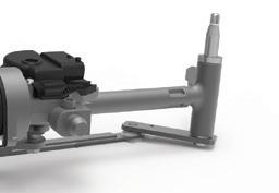


Solved: Cold Mazda 3 Runs Rough
From February 2025, Motor Age
BY BRANDON STECKLER // Technical Editor
What would you recommend doing next, given the data bullet points in last month’s challenge?
1. Replace sparkplugs and/or COPs
2. Inspect timing components
3. Evaluate fuel delivery system
4. Decarbonize induction system
For those of you who chose answer No. 3, congratulations!
The gas concentration indicated on the analyzer showed that when additional va-
porized/atomized fuel was introduced to the induction system, the engine’s combustion was closer to stoichiometry.
This points directly at a fuel starvation issue and justifies investing more time evaluating the fuel delivery system.
Answer No. 1 would be incorrect as poor performing ignition components would reflect differently in the gas analysis results. Although the gases would show improper combustion, the Lambda values would still reflect close to stoichiometry.
Answer No. 2 would be incorrect as symptoms exhibited by a cam timing issue would not be corrected with the introduction of propane to the induction system.
Answer No. 4 would be incorrect. Although carbon deposits creating a driveability fault during cold idle conditions can absorb fuel/cause a lean density misfire, the fuel absorbed in the carbon tends to evaporate and overly-enrich the cylinder charge during deceleration.
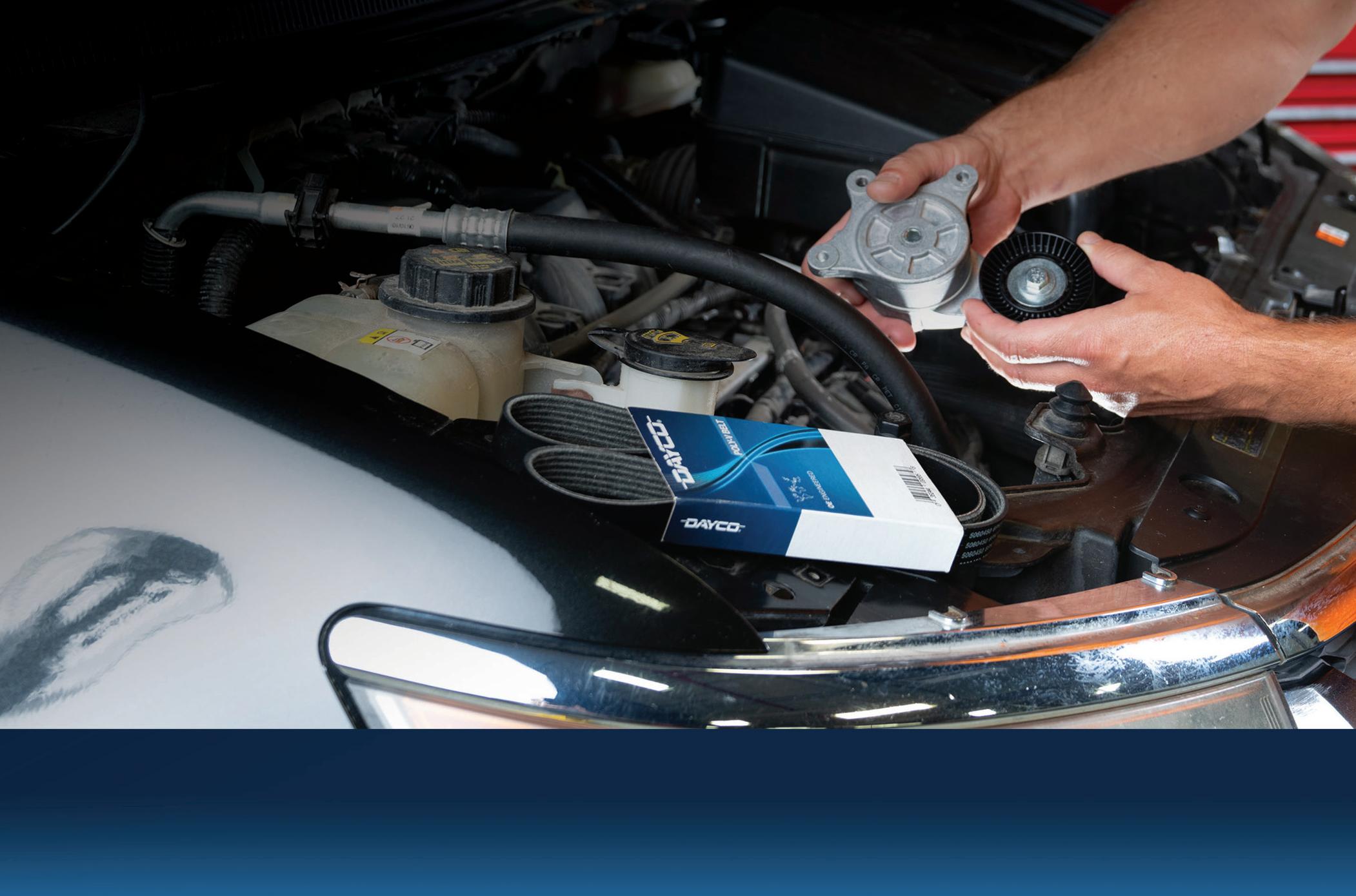
THE HEART OF LONGER RUNNING VEHICLES
Continental heavy duty aftermarket air springs, belts, hoses, hydraulics, and tensioners keep your business operating in good health. Our precision-engineered parts are built to last and extend fleet life without skipping a beat. Continental, your first choice for premium aftermarket products.
RUN STRONGER , LONGER


Shop Fire Risks
What technicians need to know about the dangers and differences between EVs and gas-powered engines.
BY CRAIG VAN BATENBURG
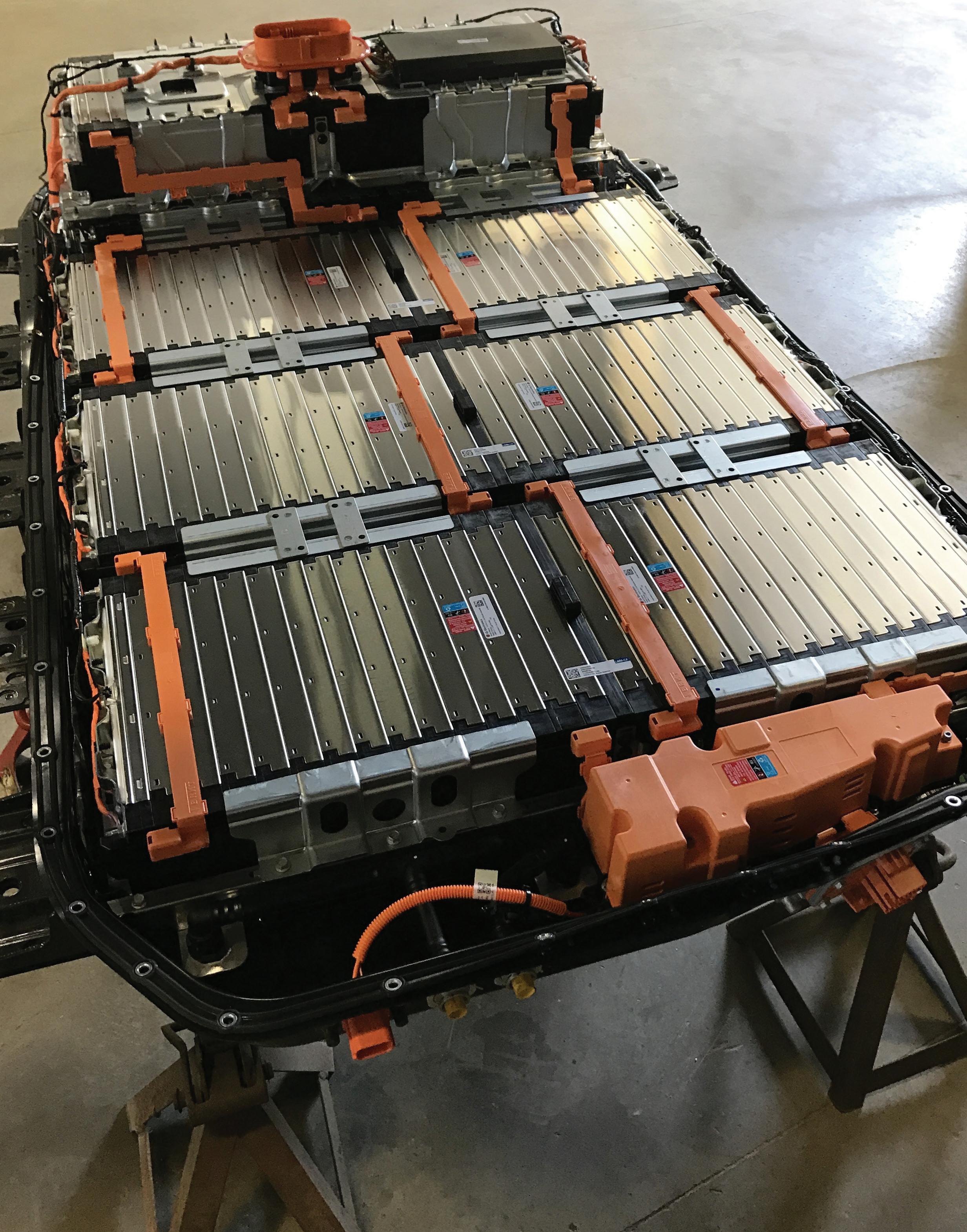

CHEVY BOLT EV HV battery with cover removed. All Li-ion battery packs are dangerous when opened up.
IF YOU HAVE WORKED IN THIS INDUSTRY a long time, you may have experienced a backfire and then used an oily rag to put out a carburetor fire. I have seen the burned paint on the hood of a ‘60s V8 muscle car. If a home mechanic changed an external fuel filter and the copper gaskets were not replaced, the “squirt gun” effect of fuel spraying onto the hot exhaust manifold sure made a hot mess. The good old days may have just been old and not as good as our memories trick us into nostalgia.
It is 2025. Let us take a fact-based view of a thermal event, as my engineering friends like to call them. This is a subject that many people, including my younger self, would make jokes about without understanding the aftermath of a simple mistake that led to serious consequences.
Here are the facts as best I could gather. Electric vehicles (EVs) are less likely to catch on fire than gasoline-powered vehicles. Some studies suggest that the risk of an EV fire is 20 times lower than that of a gasoline-powered car. A 2022 study by the Swedish Contingencies Agency found that gasoline and diesel vehicles produced 68 fires per 100,000 vehicles, compared to 3.8 fires per 100,000 for EVs. A report by the UK’s Guardian newspaper found that EVs are less likely to catch fire than gas-powered cars, but that study did not offer much in the way of the analytical process. A 2020 Tesla internal report suggested there was one Tesla fire for every 205 million miles traveled, but that was not an independent view.
If there is an EV fire in a repair shop, that is a major news story. As a member of the International Motor Press Association (IMPA), I stay up to date with that type of news. The number of EV fires in U.S. shops may total five since 2010, when the Nissan Leaf and Chevy Volt went on sale. So why all the buzz about EVs burning down your shop? Consider this news story from a Pittsburgh, Pa. news outlet on Oct. 28, 2023:
“An investigation is underway after a
vehicle repair and service facility caught fire on Friday morning. According to Pittsburgh Public Safety, around 6:15 a.m. the Pittsburgh Bureau of Fire was called to the 800 block of Gross Street for reports of a fire. Once they arrived, they found a vehicle inside the repair and service shop on fire and it took nearly 45 minutes for crews to fully extinguish the fire. Due to the nature of the fire, crews remained on scene for nearly seven hours to make sure the vehicle did not reignite. While an investigation is underway, early signs point to an electric vehicle lithium-ion battery having ignited.”
According to my research, the 800 block of Gross Street is a few blocks past a residential street that dead ends under an elevated expressway. That last few blocks are old factory buildings. The shops looked to be unmarked with no signage and graffiti on the exterior. This shop does not represent the best of us.
Although exact numbers are difficult to pinpoint due to the varied nature of shop operations and reporting practices, data from the National Fire Protection Association (NFPA) indicates that fire departments respond to an average of around 4,150 fires at service stations or gas station
properties per year, which includes repair shops that might be located on these properties. The total number of motor vehicle repair shops is about 180,000 in the USA.
ACDC has had a long history with hybrid and plug in cars and trucks. Ed Rueda owned a shop in Petaluma, California named Hybrid Haven. In my travels I ended up teaching a hybrid and EV class at his shop about the year 2010 or 2011 on a Saturday. I got to know Ed well as the next day we went to church together. Over the years we would visit by phone or get together in Las Vegas for the November “Industry Week” event. As a BMW racer, Ed met Roger Rodas, another
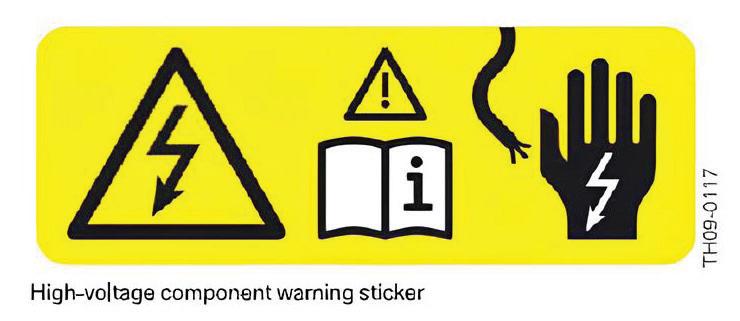
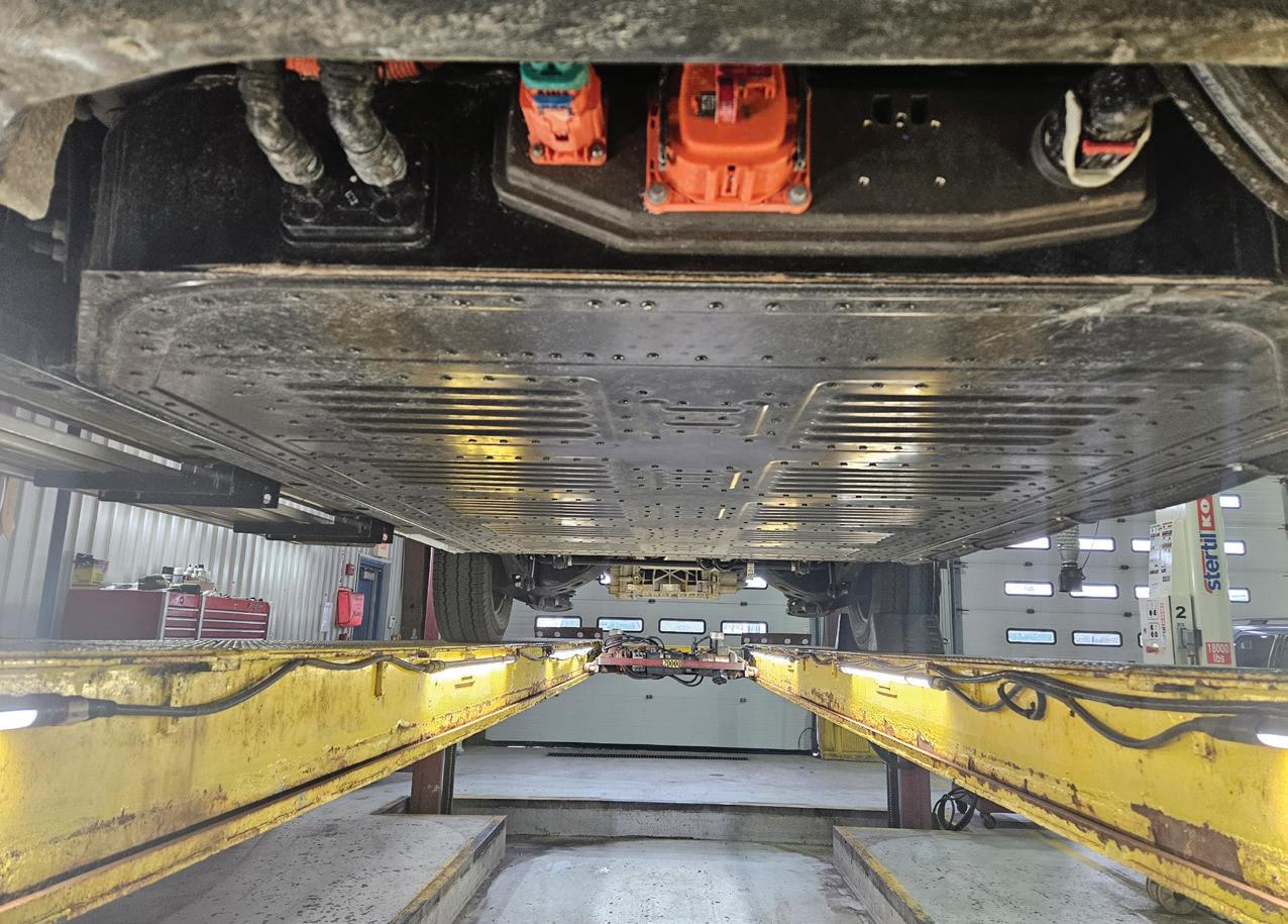
2024 FORD E-Transit electric van. View of the HV battery pack. ACDC
BMW WARNING label. ACDC
Each high-voltage component is clearly labeled, on its housing or casing, to enable Service Personnel and vehicle users to identify the possible hazards associated with high voltages and the precautions that must be taken when handling them.
CAUTION! The electric motor electronics is a high-voltage component!
BMW race car driver at the race tracks in California. With that shared interest, Ed got to know Roger. At their next visit at the track, Roger told Ed he was in business with Paul Walker, who you know from the Fast and the Furious movies, and they owned a high-end repair shop called Always Evolving. They employed Umesh Patel as their head technician. In the summer of 2013, Umesh took the ACDC class called “Up Your Voltage” to prepare for a franchise called Hybrid Haven, that included Ed, Roger, Paul, Umesh, and myself. There was one other person I met later who was hired to procure the parts needed to supply the Hybrid Haven shops ready to launch all across the USA. This team was ready to put this plan into action. On Nov. 30, 2013, Roger and Paul died while driving a 2005 Porsche Carrera GT. Had they been driving a Porsche Taycan Turbo S (one second faster in the quarter mile than the GT), they would have likely survived that accident. It was not the crash that killed them, but the fuel used to drive the car. (Ed died a few years later from natural causes.)
If you are not afraid of working on high voltage systems you are either ex-
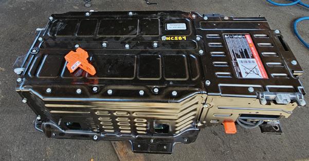

tremely well trained already or very naive. Before you pick up a wrench and head over to any high voltage vehicle, and especially if you are opening up a high voltage battery pack, make sure you know what you are doing. It is imperative that you stay safe, as you owe it to yourself and your co-workers. To do that, electricity must be your friend. If you have any doubts about a future in the automotive, heavy-duty truck and bus, or two-wheel repair industry, get the training you may lack in high voltage circuits, wiring diagrams, and the proper use of all the electrical equipment. You will need this foundation to analyze, diagnose, and test electrical systems of any voltage, from 5 volts to 1,000 volts. Some heavy-duty vehicles are now ready for delivery that will use systems that are close to 1,000 volts DC.
To master the electrical side of modern xEVs (a name that ASE coined last year that refers to any vehicle that can drive with a high voltage system), it starts with the basics. The responsibility of the success of any communication is with the reader or listener (that means you), so be engaged in the learning by asking questions about the things you do not understand. When you don’t know what someone is saying, or you are having a hard time understanding your teacher, you are learning. Don’t accept an answer to your questions until you really understand the answer. Dig deep when needed and study hard. Your future may be a mix of cars, trucks, and motorcycles — anything from two wheels to 18 wheels. Every

year more xEVs are sold and as they age you will be asked to fix them. The basic work is the same on low voltage (LV), intermediate voltage (ITV) or high voltage (HV) with the biggest difference being that HV is lethal. Never get lazy around any potential danger.
To put this in perspective, gasoline is one of the most dangerous substances you will handle and each year thousands of people worldwide die because of the gasoline in the tank. Be aware of your surroundings and the risks inside the repair shop. Some jobs require putting your life at risk, but a high voltage vehicle technician’s job is not one of them. Be safe. Gasoline, as well as high voltage and hydrogen all have risks.
There are four main types of electrical injuries: Flash, fire, lightning, and high voltage circuits. Three of these are possible when working on an xEV (lightning is not one of them) but all can be prevented.
Flash injuries, caused by an arc flash, are typically associated with superficial burns, as no electrical current travels past the skin. What is an arc flash? An electric arc is a form of electrical discharge that occurs between two electrodes as electrical current ionizes gases present in the air between them. This type of current, also known as plasma, passes through air. This type of electrical current may occur in xEV work but it would be very rare. (Many OEMs do not require techs to wear arc flash clothing in the repair of their high voltage vehicles.)
Fire injuries occur when an arc flash ignites an individual’s clothing, and electrical current may or may not pass through the skin in these cases.
Lightning injuries , involving extremely short but very high voltage electrical energy, are associated with an electrical current flowing through the individual’s entire body.
Circuit injuries involve an individual becoming part of an electrical circuit. In these cases, an entrance and exit wound is found.
FORD C-MAX plug-in pack. ACDC
PARROTTA’S AUTO Repairs has been trained on HV safety. ACDC
THESE TECHNICIANS also work on motorcycles. This Zero SR/F is all electric. ACDC
Technicians can work safely or not. It is your choice. You are the most valuable part of any repair business, so give your best and expect something in return.
The two components that are installed in a high voltage vehicle that can store a lethal amount of electricity are the high voltage (HV) battery pack and the HV capacitors.
Solid State Battery Cells
Generally speaking, the word “dendrite” can apply to a nerve ending in your body or a small hairlike structure that grows between the plates in a Lithium cell. Dendrites can reduce the capacity of a cell and also start a fire. When solid state electrolytes are perfected, and used in Li-ion cells, then fires may be a non-issue
going forward. The HV battery computer manages the cells so the issue of dendrites does not usually affect performance, life span, or safety. The technological race for a better battery is moving forward with billions of dollars invested.
Once a Li-ion cell starts to burn, it cannot be put out as it does not need oxygen to keep the fire active. The electrolyte has everything it needs to burn until it has consumed itself. Fire departments keep flooding the EV with water to try and keep other cells in the pack cool, so that those cells do not ignite. This is the single most serious issue with EV fires. This can only be solved by engineers.
Gasoline
Fuel-related repairs are common in all
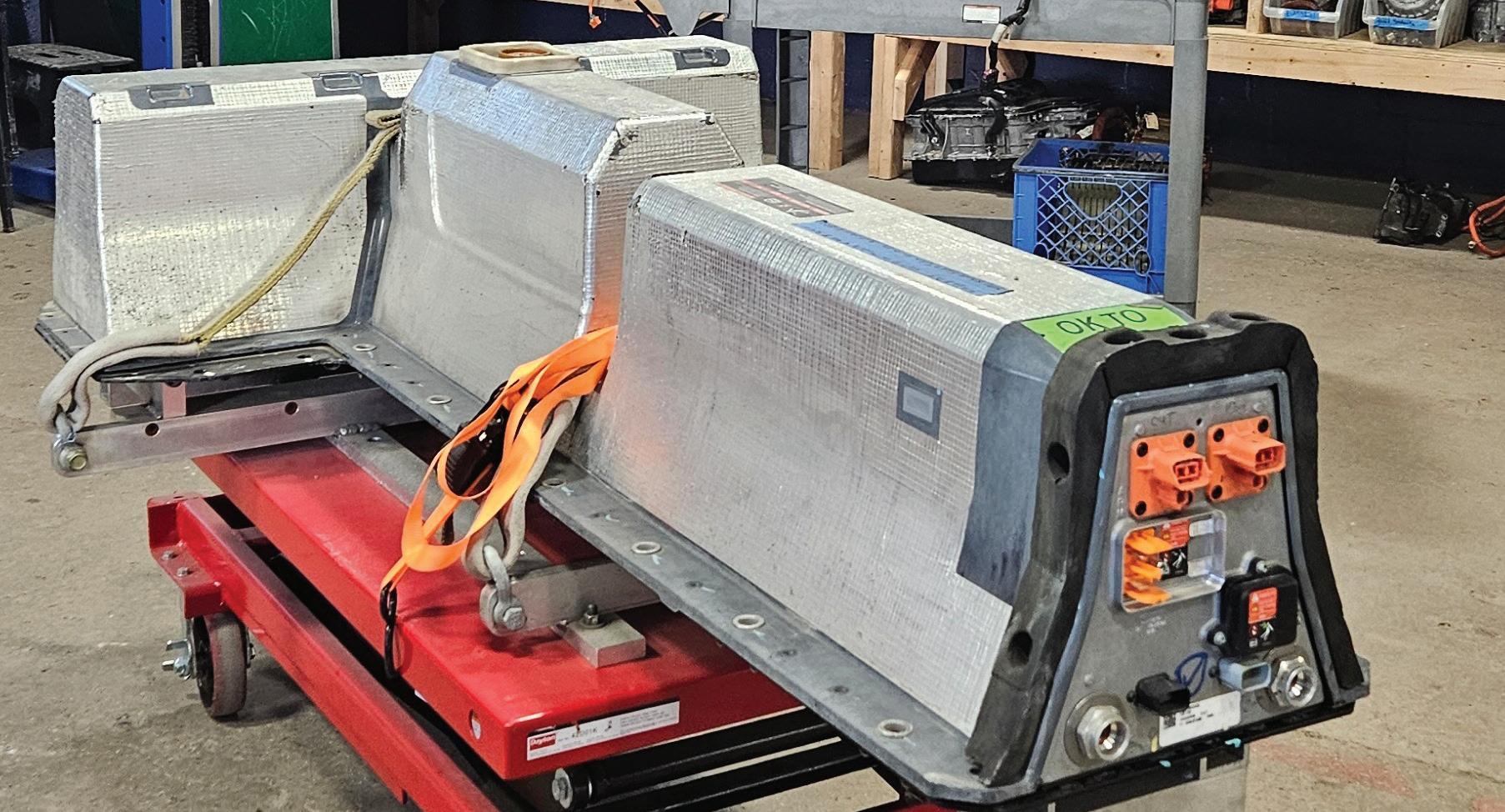
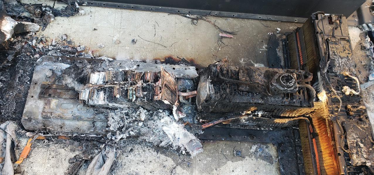
auto repair shops, unless the shop only works on electric powered vehicles. (That number might be counted on one hand.) When a technician services or replaces a fuel pump, he or she may have to drain and/or remove the gas tank. If this is not done properly, the technician, others in the shop, and the entire business could be in danger. The most dangerous situation in a repair shop is not liquid gasoline, it is the vapors. Those vapors are the biggest threat — not a high voltage battery. The gasoline vapors can move through the shop and easily ignite by a spark from a tool, a drop light, an extension cord, or a lit cigarette. What more do you need to know about gasoline? Every technician in the world has worked with gasoline and the majority have some training with the safe handling of this deadly liquid. Most people work in safe environments with shop owners who care about their employees.
The more you learn about high voltage systems, Li-ion battery packs, the related safety systems built into xEVs, you may agree with my own evaluations of the risks associated with both fuels, gasoline and electricity. Will EVs go away? No. Will your customers that owned a gasoline vehicle come back to you for service when they trade it in for an electric car or truck? Sure — if you offer that service.

CRAIG VAN BATENBURG is the CEO of ACDC, a hybrid and plug-in training company based in Worcester, Mass. ACDC has been offering high voltage classes since 2000, when the Honda Insight came to the USA. When EVs were introduced in 2011, ACDC added them to their classes. Reach Craig via email at Craig@ fixhybrid.com or call him at (508) 826-4546. Find ACDC at www.FIXHYBRID.com.


THIS CHEVY Volt battery caught on fire. The technician did not properly torque the HV cable connections and one was loose. This happened before it was installed into the vehicle. ACDC
CHEVY VOLT Li-ion pack on factory lift fixture. ACDC


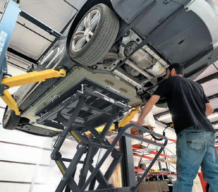


AUTOMOTIVE PRODUCT GUIDE

12-point offset reversible ratcheting head
The NORA150XL from VIM Tools is a 12-point offset, flexible, reversible ratcheting wrench head that can be used with any length extension to provide the ideal length for users. The set accepts 3/8” drive extensions and flexes to 90 degrees. It is designed to solve the issue of having wrench sets in different lengths and provide a solution to storing several different-length wrenches in a toolbox. Covers sizes from 14mm to 19mm and comes in patented MAGRAILS which are low-profile magnetic socket rails.
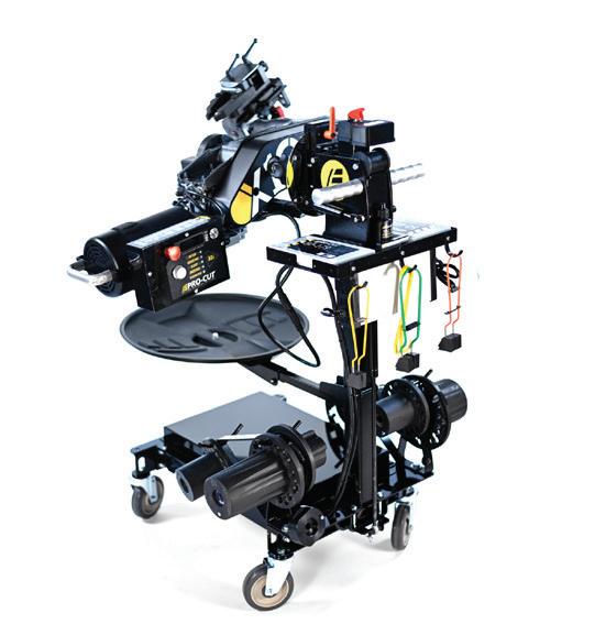
Machines up to 30 discs on a single charge
The Pro-Cut International X19 Cordless On-Car Lathe is the only rotor-matching system powered by a 48V 50Ah rechargeable battery, which can provide over eight hours of operating time on a single charge. The X9 can be plugged into wall power as well. Its battery comes with protection against overcharge, over-discharge, short circuit, over-current, and high temperatures. It uses a variable-speed DC motor that delivers clean, consistent power. The X19’s computer system features disc tracking, maintenance alerts, variable speed control, and a battery management system.

Flame-resistant PPE gloves
The AeroDex FR from Magid is a patent-pending, flame-resist, and cut-resistant glove designed for comfortability. Magid combined the flexible, cut-resistant AeroDex core with the materials used to make life-saving items like bulletproof vests to create this glove. The glove is 25 percent lighter, with half the thickness of comparable cut-resistant aramid materials, and is engineered to feel cooler. Additional features include tactile sensitivity with ANSI A6 cut protection and a foam neoprene palm coating.
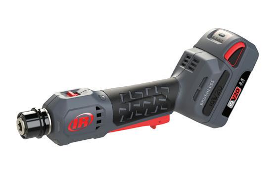
Can perform up to 45 repairs on single battery
The Ingersoll Rand 20V Cordless Tire Buffer, No. G4911, can perform up to 45 repairs on a single 2.5Ah battery and prevents expensive repair mistakes with a dedicated two-speed selector for reaming and buffing that controls max RPM, in alignment with U.S. Tire Manufacturers repair guidelines. The patent-pending angled battery design provides increased tool accessibility inside small tires without the maneuverability restrictions of an air hose. The G4911 is up to 25 percent quieter with 50 percent less vibration than competitive air tools, according to the company. A low-profile lever throttle fully recesses into the slim handle for maximum control while creating the repair surface. A 20 lm LED eliminates the need for additional lighting.
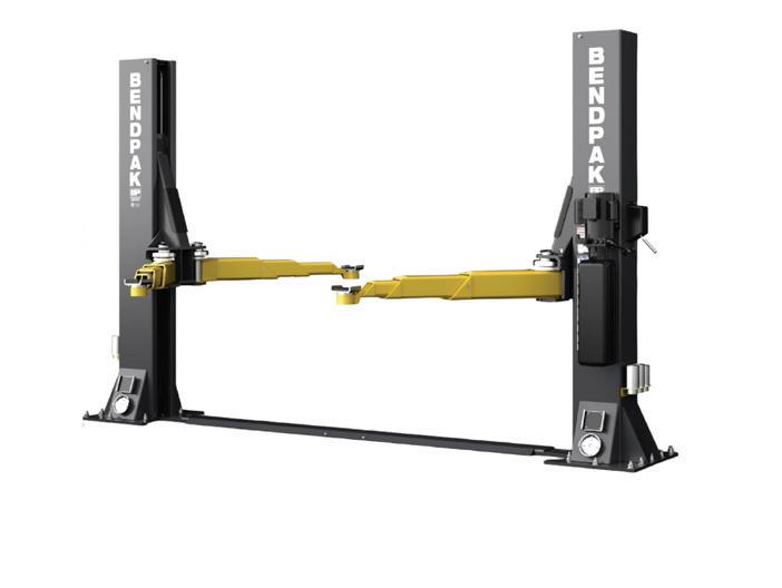
Loads symmetrically or asymmetrically without switching arms
The BendPak 12AP-SRT Short Two-Post Lift features the company’s Automatic Swing Arm Restraint System, which uses a forged-steel design to provide over 2,000 lbs of load-holding force and 360 degrees of grip. The triple-telescoping arms offer versatile arm positioning and can be set up in either symmetric or asymmetric configurations without having to switch out arms. The 12AP-SRT has a lifting capacity of 12,000 lbs, safety locks spaced every 3” in each column, and a durable powder coat finish.

Features adjustable temple tips
The Bluetooth-Enabled Safety Glasses, No. SOSGBTBLK, from Snap-on, blend eye protection with smart features like audio connectivity to phones and other devices. The bone conduction speakers are compatible with hearing protection, ensuring techs stay aware of their surroundings and remain safe. The SOSGBTBLK allows techs to answer calls or listen to music by pressing a button located on the side of the glasses, eliminating the need to touch their ears with work-exposed hands that is often associated with traditional earbuds. Designed for all-day comfort with adjustable temple tips and a 6-hour run-time.
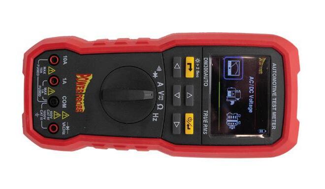
Identifies parasitic draw and locates active circuits
The Power Probe DM300AUTO Automotive Test Meter can measure current directly up to 30A and can measure and display the current flowing through a fuse without requiring the removal of the fuse, making it ideal for identifying parasitic draw and locating active circuits. It features a large TFT color display with a user-friendly interface, and it can perform a number of test functions, including step-by-step testing of the alternator output or starting cranking voltages in the supply circuit.

Features a bendable Stay-Flex body
The 24” Stay-Flex Magnetic Pickup Tool, No. SFM24G, from Matco Tools, is designed for the effortless retrieval of fasteners and small parts in those hard-to-reach spaces. Its bendable Stay-Flex body allows the user to shape the tool as needed for easy access. Equipped with a powerful 8-lb magnet, this heavy duty pickup tool can lift heavy items with ease, according to Matco.
3-PIECE THREAD RESTORER FILE KIT
Restores damaged external threads, any diameter, right or left hand
Select the proper number of threads per inch or millimeters per thread, and overlapping several good threads, work over the area using regular file strokes
Rethreading files are highly tempered for strength and durability


Features three full-size and slim drawers
The Bench-Top Tool Chests, Nos. 91879 and 91881, from Wiha Tools, include top storage, three full-size drawers, and three slim drawers. The tool chest features a combination/key lock, comfort grip handles, and gas struts for improved opening and closing safety. It is built for durability and longevity, constructed from cold-rolled steel, and finished with a durable powder coat. Comes in white (No. 91879) or black (No. 91881).


From micronized carnauba to the latest graphene and ceramic formulas, our full spectrum of BRIGHTLINE professional car appearance products has everything you need to make your customers’ cars – and your business – shine. So whether you run an automatic, self-serve or hand-wash and detail operation, make the smart choice with BRIGHTLINE.


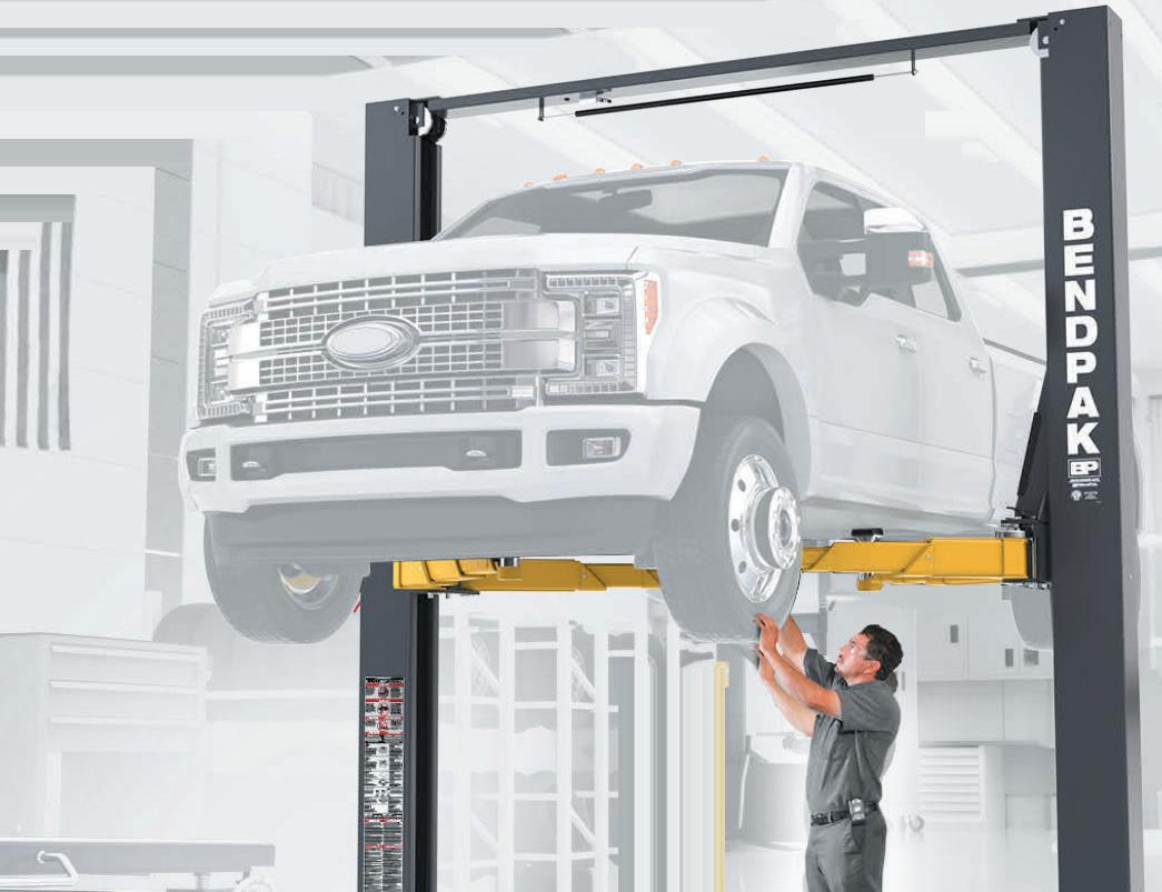


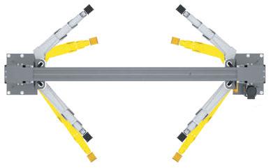


TECHNICAL SERVICE BULLETINS
INFORMATION COURTESY OF MITCHELL 1

MAZDA DRIVER MISTAKE

CHEVY COOLANT ELECTRICAL CONNECTIONS
This bulletin applies to 2019 Mazda CX-3 and MX-5 vehicles (equipped with Start/Stop). Some customers may experience a check engine light on. DTC P061B:00 may be stored in the PCM. This condition will likely occur as a result of one of the following causes:
• Engine cranking was interrupted by releasing the brake pedal.
• The start button was double-depressed while the engine was still cranking.
• Inspect the FFD (freeze frame data). If FFD indicates that the DTC was not set during cranking, follow the diagnostic instructions on MGSS online.
If DTC P061B:00 was set while cranking, do not replace any parts. Clear the DTC and inform the customer to allow the engine to completely start before releasing the brake pedal and to only press the start button once.
(Photo: Mazda)
This bulletin applies to 2020-2021 Chevy Blazer vehicles equipped with a 2.0L engine. You may encounter the MIL on with DTC P26BB, P1098 and/or P26B7 stored in current or history. During diagnosis, be sure to inspect all engine coolant control valve electrical connections for signs of contamination or corrosion.
(Photo: Chevy)

BMW GEAR SELECTOR SWITCH
This bulletin applies to 2022 BMW
vehicles. The gear selector switch (GWS) consists of the control electronics circuit and the selector lever. The sensors for recording the gearshift lever position and inhibiting inadvertent gear shifts are integrated in the control electronics. When fault code 802683 (selector lever knob exchange without disconnection of battery) is stored, this indicates that the GWS was exchanged without isolating the vehicle battery. Removal of electronic components without first disconnecting the battery may result in a short circuit, causing component damage. Once the fault code 802683 is stored, it cannot be deleted and only becomes inactive after a GWS replacement. Isolate the battery, then replace the GWS.
(Photo: BMW)

FORD BRONCO PARK AID
Some 2021-2022 Ford Bronco vehicles equipped with parking aid sen -
sors may exhibit a park aid system that does not remain deactivated after the vehicle has been off for more than five minutes. The vehicle may exhibit false alerts which may cause it to activate while driving or towing due to the presence of a front winch. This may be due to the software within the instrument panel cluster.
• Reprogram the IPC using the latest software. This could take up to three hours if using a VCM 3 or VCMM and up to six hours if using a VCM 2. However, no technician interaction is needed during programming.
• Refresh the park aid system by cycling all parking aid sensors from on to off, several times, ending in off.
• Turn the vehicle off and let it sit for at least five minutes.


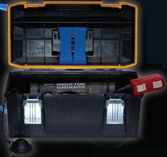


• Test drive to confirm operation. If the park aid system fails to remain disabled, disconnect the vehicle battery for at least five minutes, connect and repeat the final step.
(Photo: Ford)
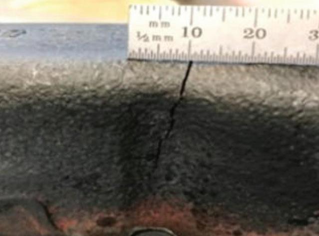
RAM TICKING ENGINE
This bulletin applies to 2019-2012 Ram 1500 trucks equipped with a 5.7L engine. The customer may
complain about an engine tick noise when cold. The exhaust manifold(s) may be cracked.
• Start the engine when cold. Listen for a ticking noise that stops when the engine warms.
• Shut the engine off and allow to cool.
• Remove the exhaust manifold heat shields from the side that is suspected of leaking.
• Re-start the engine when cold and listen for the noise source along the exhaust manifold(s).
• Visually check for a cracked manifold and confirm that what you see is not a casting parting line or a casting fin.
• If a crack is found, replace the manifold.


Replace all fasteners to prevent bottoming in the cylinder head. According to the bulletin, fasteners were lengthened when tie bars were added to the exhaust manifolds. The repair kit includes tie bars. Tie bars must be installed even if not originally equipped. Note that the front right side fastener is 5mm shorter than other fasteners.
(Photo: Mitchell 1)

NISSAN STUCK PUMP RELAY


This bulletin applies to 2019-2021 Nis -
san Altima vehicles. DTC B12A-72 (fuel pump relay stuck open) may be stored when the IPDM monitor circuit internally sees 0V to ground at pin No. 46. This is caused by an internal short to ground in the IPDM or one of the IPDM fuses is open. If B12A3-72 is current or reoccurs after erasing DTCs, inspect the fuse first. In the Altima application, check fuse No. 58. If the fuse is not open, replace the IPDM.
(Photo: Mitchell 1)

LEXUS BUCKING THE COLD
All 2021-2022 Lexus LS500 vehicles may exhibit a surge/bucking condition when applying throttle of less than 20%. This condition is only felt after the vehicle has cold soaked and reduces as the vehicle warms up. The condition is no longer present once the vehicle reaches operating temperature. The ECM logic has been revised to address this condition.
Use Techstream to confirm if the ECM calibration has been updated. If it has not been updated, flash reprogram the ECM with the latest available software.
(Photo: Lexus)

Some 2020 Lincoln Corsair vehicles
equipped with an 8F35 or 8F40 transmission/transaxle may exhibit an unable to engage park condition, with MIL (wrench) lamp on and DTC P07E4 stored in the PCM memory. There will also be a shift system fault warning message displayed and the electronic parking brake will be automatically applied when park is requested. This condition may be caused by an incorrect underhood section of the transmission park manual release cable or the underhood section of the transmission park manual release cable not in the proper stowed position. Inspect the operation of the transmission park manual release cable and if necessary, replace the cable.
• Using a borescope, verify the underhood transmission park manual release cable part number.
The part number label is located on the cable under the battery tray. Refer to the parts catalog to verify the correct part number. If the P/N is incorrect, replace the cable. The correct cable P/N for the 8F35/8F40 transmissions is LX6Z-7D246-K. The instrument panel side of the cable is P/N LX6Z-7D246-L. If OK, go to the next step.
With the vehicle in the key-on-engine off (KOEO) mode and the brake pedal pressed, fully actuate the cable to the override position (which should activate a cluster message “Park is not available — apply park brake before exiting” and release the cable. Make sure the cable handle cover is reinstalled. Make sure to pull the cable straight out. Do not pull at an angle. Does the fault warning message disappear? If yes, clear the


LINCOLN CORSAIR PARK ISSUE
DTCs. If not, replace both sections of the cable. Refer to service manual section 307-05.
(Photo: Lincoln)

JEEP CHECK THE PEDAL
This bulletin applies to 2021 Jeep Cherokee vehicles built on or after March 5, 2021, and on or before Aug. 20, 2021. The customer may complain that the vehicle lurches forward, and/or RPMs surge while stopped or in Park.
Run a scan and verify that all systems are working as designed before proceeding.
• Remove the accelerator pedal to check for the date
• Look to see if the pedal assembly has the date code of either C2105 and C2106. If yes,
proceed to the next step. If not, go to step 4.
• Install the new pedal assembly.
• Install the original pedal assembly. The pedal assembly P/N is 04581652AE.
(Photo: Mitchell 1)

ALFA ROMEO FORWARD COLLISION WARNING
This bulletin applies to 2020 Alfa Romeo Giulia and Stelvio vehicles built on or before Dec. 31, 2019, or on or before Dec. 20, 2019. Customers may experience a MIL on. One or more of the following DTCs may be set:
• B1006-49 (camera – internal electronic failure)
• C141C-86 (video camera private can communication failure – signal invalid)
• C1999-86 (data set failure – signal invalid)
In addition, the EVIC (electronic vehicle information center) may display “Forward Collision Warning (FCW) Limited Functionality Front Camera Service Required.”
• Using the scan tool (wiTECH 2), perform a “Restore Vehicle Configuration.”
• Perform a “Proxi Configuration Alignment.”
• DTCs will still be active. Cycle the ignition off, and back to on. The codes should change from “Active” to “Stored.”
• Clear all DTCs.
• Remove the Micro Pod from the vehicle.
• Cycle the ignition off, exit the vehicle, lock the doors and let the vehicle sleep for 10-15 minutes (keep the FOBIKs away from the vehicle to keep them from waking up the bus). Place the ignition in the on position and connect the wiTECH 2. Verify that codes have not returned. If codes return, perform normal diagnostics.
(Photo: Alfa Romeo)

SCAN TO READ MORE TSB s ONLINE


NO. 159 Forced Induction
BY BRANDON STECKLER // Technical Editor

FOLLOW MOTOR AGE MAGAZINE ON YOUTUBE TO SEE NEW VIDEOS AS THEY ARE RELEASED.
LET’S DIVE INTO FORCED INDUCTION systems — how they are leveraged on today’s internal combustion engines, why they exist, and, equally as important, how to go about troubleshooting them when driveability faults begin to surface.
As ever-tightening emissions standards prevail, the internal combustion engine that exists today has seen some major improvements over the last two decades, and with good reason. The corporate average fuel economy (C.A.F.E) standards set an initial bar of 52.5 mpg by this year. To accomplish this goal that aggressively meant a major change to how engines are constructed and how they breathe, meaning their displacement.
Vehicle configurations that traditionally call for a large-bore V8 engine can
get by just fine with average-sized V6s or even L4 configurations. But how is that accomplished? By increasing the engine’s volumetric efficiency, or force feeding the engine. Forced induction systems allow the engine to pump more air than it could through natural aspiration. And when more air is pumped more fuel can be delivered which means more torque and horsepower can be extracted from these tinier power plants.
But why do the manufacturers go through such trouble? The answer is they are forced to. The C.A.F.E. standards demand better fuel economy and with the more stringent tailpipe emissions standards set forth, not only must the manufacturers reduce the production of harmful hydrocarbons, carbon monoxide,
and oxides of nitrogen, they now must more-stringently manage carbon dioxide.
Traditionally, the production of carbon dioxide is looked to as an indicator of an engine’s combustion efficiency. However, studies have shown that carbon dioxide contributes to global warming by blanketing the earth. And the only way to eliminate its production is by either reducing the intensity of the combustion event or eliminating it altogether. By extracting more out of smaller powerplants, the forced induction systems of today can be found on nearly every internal combustion engine powerplant in consumer vehicles out there.
Learn more about how this is accomplished on today’s vehicle in The Trainer.